safety and communication system (scs) for passengers in
19
SAFETY AND COMMUNICATION SYSTEM (SCS) FOR PASSENGERS IN RAILROAD TRANSPORTATION ME5643-Mechatronics: Integrated Term Project Xiaoyang Lin, Eathan Hsu, Eduardo Suescun Abstract: As World population is exponentially increasing big cities face traffic and safety challenges related to railroad and rapid ground transportation projects. For this reason, to avoid collisions and allow a better communication between train, central control headquarters, and passengers new technologies are being developed by means of very sophisticated technologies. This project, being focused in the GK-12 education learning, is not intended to create new tools to mitigate real problems but rather is an excellent opportunity to share basic concepts of electronics and mechanics to young minds, and encourage them for science exploration. The project involves a Safety and Communication System (SCS) for railroad transportation. Five specific scopes were achieved by using light sensors, servo-motors, infrared sensors, relays, 555 timer, Ethernet cards, Twitter platform, and two microcontrollers: Arduino and Basic Stamp 2. The final result is an integrated circuit mounted in a small-scale railroad system that is capable to intelligently operate according to different scenarios such as darkness, emergency stops, communication via social networks, and safety conditions.
Transcript of safety and communication system (scs) for passengers in

SAFETY AND COMMUNICATION SYSTEM (SCS) FOR PASSENGERS IN
RAILROAD TRANSPORTATION
ME5643-Mechatronics: Integrated Term Project
Xiaoyang Lin, Eathan Hsu, Eduardo Suescun
Abstract:
As World population is exponentially increasing big cities face traffic and safety challenges
related to railroad and rapid ground transportation projects. For this reason, to avoid collisions and allow a
better communication between train, central control headquarters, and passengers new technologies are
being developed by means of very sophisticated technologies. This project, being focused in the GK-12
education learning, is not intended to create new tools to mitigate real problems but rather is an excellent
opportunity to share basic concepts of electronics and mechanics to young minds, and encourage them
for science exploration. The project involves a Safety and Communication System (SCS) for railroad
transportation. Five specific scopes were achieved by using light sensors, servo-motors, infrared sensors,
relays, 555 timer, Ethernet cards, Twitter platform, and two microcontrollers: Arduino and Basic Stamp 2.
The final result is an integrated circuit mounted in a small-scale railroad system that is capable to
intelligently operate according to different scenarios such as darkness, emergency stops, communication
via social networks, and safety conditions.

Introduction
To really understand the full impact of railroad safety program in the United States
during the past 100 years, it is necessary to take a look at the evolution of the railroad
machinery, and its relationship with the reduction of injured and deaths. There is no doubt that
that all railroad safety applied program, have saved tens of thousands of lives and prevented
hundreds of thousands of injuries (McDonald, 1993). The overall accident rates have fallen
62.8%, track-and equipment-related accidents have fallen 75.2%, and in-service deaths for
railroad employees have been reduced more than 46% (Federal Railroad Administration, 2005;
and Federal Highway Administration, 2007).
Today’s trains are longer, faster, and heavier than those in the last century; however,
with the higher speeds and heavier trains there is also a greater potential for damage and loss
of life in accidents. Recently, the lack of attention by a train driver let to a fatal accident in Los
Angeles, CA named as the Chatsworth train collision as shown in Figure 1. According to
National transportation Safety Board (2008) two trains, Union Pacific and Metrolink, collided on
September 12, 2008 where 25 people resulted dead and 135 more injured.
Figure 1: Rescue operations at the site of the Chatsworth train collision.
Based on the aforementioned and others collision episodes not reported herein, a new
regulation called the “Rail safety improvement act of 2008” is to be implemented by using the
Positive Train Control (PTC) system ((Federal Railroad Administration, 2009). This safety
program integrates command, control, communications, and information systems to manage
train movements with safety, security, precision, and efficiency. Therefore, it is estimated that
20,000 locomotives and about 100,000 miles of track would need to be equipped with PTC.

Likewise in Europe, the German Aerospace Center (DLR) is also implementing a safety
program for railroads called as “Railway Collision Avoidance System (RCAS)”. This is an
additional safety system that can be arranged over any existing safety infrastructure in train
networks. The main idea is to transmit the current and intended position trains by using satellite
navigation systems. This enables drivers to have an overall knowledge of the traffic around him.
Taking advantage of the Mechatronic concepts, tools, and knowledge gained along the
course, authors of the present project developed a basic Safety and Communication System
(SCS) for passengers in railroad transportation. This project neither intends to be all
systematically advanced non comprehensive in terms of latest applied technology in rail road
systems, but applied to elementary educational to encourage young people to become
explorers of future technologies to enhance safety programs for train passengers.
The concept of the Safety and Communication System (SCS) in Railroad
Transportation
The SCS project is designed, by using HO- scaled railroad tracks; train locomotive; and
Mechatronic tools to integrally achieve the following tasks:
1. Avoiding railway accidents due to unattended driving machines or locomotives.
2. Communication train users the position and waiting time for the next train to arrive a
specific station.
3. Improving the train visibility and detection by setting up a lights set, in which their
intensity vary according to the light exposure.
4. Controlling crossing gates motion when a certain train approaches such intersection.
5. Switching train tracks due to safety or plans change purposes.
Descriptions and details regarding all tasks involved in the present project are to be
presented in the following paragraphs. A general discussion of setup, sensors and actuators,
and electronic circuits are included.

a. Emergency Stops in train Stations
Using the Infrared (IR) LED and sensor, and controlling it by using the Arduino
Microcontroller, it is possible to automatically stop a locomotive. As an application example,
considering a train running between two stations, which in any situation, may result unattended
due to many factors such as theft, kidnapping, or sudden loss of the driver due to health
conditions. In that case, operation central office is aware to activate the IR beam, which means
that even though there is not train controlled by a human being, train will stop on next station
and does not run until another employee takes care of the situation.
Figure 2: Infrared beam of a IR sensor and LED (left), and train automatically stopped at station
Figure 3: Electronic circuit emphasizing IR arrangement connected to Arduino.

b. Light system
In order to avoid train accidents during night time, a dual-light system is directly attached in
front of the locomotive. Light setup is able to turn on and off depending on the brightness
outside. A photoresistor is used to detect the change in light outside the train. By means of an
Analog-to-Digital Converter, the Basic Stamp 2 has the capability to identify outside light and
allows for turning on either one or two LEDs depending on the darkness levels.
Figures 4 and 5 show a picture and electronic circuit of the light arrangement respectively. In
the picture, Basic Stamp 2 placed in back of the train is shown. It carries all resistors, ADC, and
photoresistor to sense light.
Figure 4: BS2 carrying a light system(left), and train operating under dark conditions; lights on(right)
Figure 5: Electronic circuit of the train light system connected to BS2.

c. Twitter Interface with System
One of the best applications of social networks is that traffic and time information may be
broadcasted for users to notice when the next train is approaching any station. Within the main
goals of the current project Twitter is being used to automatically post the information on a
public screen. In order to achieve this scope, an Ethernet shield was used. Such Ethernet
device is able to provide the microcontroller ability to connecting to internet, and therefore
communicate with Twitter on real time. As a result, any time any train reaches one station, an
informing post will be shown on the user Twitter account.
Figure 6: Picture of a Lin’s Twitter account showing messages of train reaching station
Figure 7: Electronic circuit of the Communication system using an Ethernet shield and Arduino.

d. Track switch
In order to switch the tracks where train is passing through, two relays were attached directly
to the power supply. A relay is a switch that is electrically controlled. These relays use
electromagnets to control and switch mechanism. Since this circuit is managed by a low-power
signal relays can easily be used.
Figure 8: Track setup for circle path(left) and for big oval path( right)
Figure 9: Electronic circuit with shaded area where relays control track switching.

e. Automatic Railway Gate Control
Railway accidents happen at unattended railway gates and sometimes the
consequences are devastated. Often, news around the World broadcast railway accidents
occurring at unmanned railway crossings. This is primarily due to the inattention in manual
operations or lack of personnel. Using simple electronic components it was tried to automate the
control of railway gates. As a train approaches the intersection, the sensors mounted at a
certain distance from the gate sense the presence of train and consequently control the gate
action. Also an indicator light has been provided to alert the motorists about the approaching
train.
This task is conducted by using two powerful IR transmitter LED and receiver sensor to
create an IR beam. The pair of transmitter and receiver elements is fixed at opposite faces, one
inside loop and the other outside.
When the train breaks the IR beam and 2 seconds have passed, the gate motor is
turned on in one direction and the gate is closed and stays closed until the train crosses
completely. It would be better if more IR beams and sensor is placed closer in order to detect
the train approaching.
The servo motor is used as the switch of gate and been programmed to open and close
determined by microcontroller. It could be a real application in the crossway to stop the vehicles
which need to cross the railway when the train is coming. And the alarm system, which contains
blink LED light and alarm speaker, will works as a safety system.

Figure 10: Gate open for motorist to pass (left), and gate closed due to train crossing intersection
Figure 11: Electronic circuit showing the 555 timer and servo-motor to activate the gate.

Bill of materials and Prototype costs
The following table presents all materials used for this project. Also, price per units and total
price of the Safety and Communication System is included below.

Advantages versus Disadvantages
Among the advantages of this project, four points were clearly identified. First, it is
considered a straightforward model useful to create and manipulate existing train conditions. It
could be applied to teach children to understand mechatronics concepts, as well as support GK-
12 Education while having fun. The choice of small-scaled train setup provides a more
entertained component for young people to easily feel excited about project.
Second, since purchasing a new whole set of train sold in the market is far away more
expensive, the actual price of the present prototype could be, in some way, attractive for
potential customers.
Thirdly, two types of microcontroller with different programs are included. It means we
could teach students the idea of both microcontrollers at the same time. Thus, it would be a
good application of microcontrollers.
Moreover, social networks offer an extensive range of commodities and benefits to users.
In this specific project, connection with Twitter provides passengers arrival times, delays, and
train identification in any given station, which results in a positive impact on people’s schedule.
On the other hand, the prototype does not comprehensively show actual situation in the
real life. Combination of excessive noise and train speed could make the locomotive to stop on
different location than the actual train station.
Finally, nowadays there is no GSM signal in most stations, which so far could make
Twitter application useless. Not everyone uses and needs train’s notification. Right now these
types of apps are not very familiar. However, technological evolution is providing more benefits
and tools for community to achieve things easier.

Conclusion
A basic, didactic, and educational comprehensive project that involves mechatronics
concepts and tools was successfully developed. The main topic of the project was to mimic
possible conditions of safety and communication on railroad and train projects. Roadway
crossing gates, emergency stops, light system with locomotives, broadcasting via Twitter, and
track switching, were the main scopes achieved along this project. The use of two different
microcontrollers: Arduino and BS2, light sensors, IR sensors, relays, servo-motors, 555 timer
device, and an Ethernet shield were utilized to build the circuits and attach them to the small-
scale railroad system.
References
1. Federal Highway Administration. (2007). Highway Statistics 2006. Washington, D.C.: Federal Highway Administration. Online at: http://www.fhwa.dot.gov/policy/ohpi/hss/index.cfm
2. McDonald, Charles W. (1993). “The Federal Railroad Safety Program – 100 years of safer railroads”, S.I.: sn, Los Angeles County Metropolitan transportation Authority, Los Angeles, CA.
3. National Transportation Safety Board (2008). “Railroad Accident Report: Collision of Metrolink Train 111 with Union Pacific Train LOF65–12 Chatsworth, California, September 12, 2008”. Railroad Accident Report NTSB/RAR-10/01. Retrieved 2010-09-25 Washington, D.C.
4. Raslear, T.G. (1996). Driver behavior at rail-highway grade crossings: A signal detection theory analysis. In A. A. Carroll and J. L. Helser (Eds.), Safety of highway-railroad grade crossings. Research needs workshop. Volume II – Appendices (Report No. DOT/FRA/ORD-95/14.2, DOTVNTSC-FRA-95-12.2, pp. F9-F56). Washington, DC: U.S. Department of Transportation.
5. Yeh, M. and Multer, J. (2008). Driver Behavior at HighwayRailroad Grade Crossings: A Literature Review from 1990–2006 (Report Nos. DOT-VNTSC-FRA-08-03 & DOT/FRA/ORD-08/03). Cambridge, MA: U.S. DOT Volpe Center
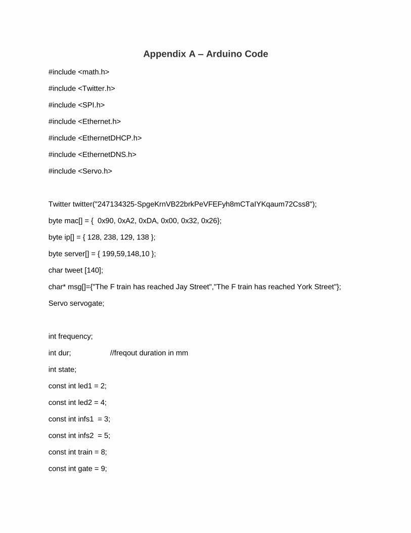
Appendix A – Arduino Code
#include <math.h>
#include <Twitter.h>
#include <SPI.h>
#include <Ethernet.h>
#include <EthernetDHCP.h>
#include <EthernetDNS.h>
#include <Servo.h>
Twitter twitter("247134325-SpgeKrnVB22brkPeVFEFyh8mCTaIYKqaum72Css8");
byte mac[] = { 0x90, 0xA2, 0xDA, 0x00, 0x32, 0x26};
byte ip[] = { 128, 238, 129, 138 };
byte server[] = { 199,59,148,10 };
char tweet [140];
char* msg[]={"The F train has reached Jay Street","The F train has reached York Street"};
Servo servogate;
int frequency;
int dur; //freqout duration in mm
int state;
const int led1 = 2;
const int led2 = 4;
const int infs1 = 3;
const int infs2 = 5;
const int train = 8;
const int gate = 9;

const int switch1 = 6;
const int switch2 = 7;
int opengate = 70;
int closegate = 130;
int sw1;
int sw2;
int v1;
int v2;
int v11;
int v22;
void setup(){
delay(1000);
Ethernet.begin(mac, ip);
Serial.begin(9600);
Serial.println("connecting ...");
pinMode(led1,OUTPUT);
pinMode(led2,OUTPUT);
pinMode(infs1,INPUT);
pinMode(infs2,INPUT);
pinMode(train,OUTPUT);
digitalWrite(train,HIGH);
dur = 1;

pinMode(switch1,OUTPUT);
pinMode(switch2,OUTPUT);
servogate.attach(gate);
for(int k = 0;k < 20;k++)
{servogate.write(opengate);}
}
void loop(){
freqout(29000,dur,led1);
v1 = digitalRead(infs1);
Serial.print("v1=");
Serial.println(v1);
freqout(29000,dur,led2);
v2 = digitalRead(infs2);
Serial.print("v2=");
Serial.println(v2);
v22 = v22 + v2;
v11 = v11 + v1;
if (v11 == 10)
{
v11 = 0;
v22 = 0;
digitalWrite(train,LOW);
twitterpost(0);

delay(10000);
digitalWrite(train,HIGH);
delay(2000);
}
if (v22 == 10)
{
v22 = 0;
v11 = 0;
sw2 = sw2 + 1;
if (sw2 == 2){
sw2 = 0;
}
Serial.println("stop for 2");
digitalWrite(train,LOW);
twitterpost(1);
if (sw2 == 0){
digitalWrite(switch1,LOW);
delay(50);
digitalWrite(switch2,LOW);
}
if(sw2 == 1){
digitalWrite(switch1,HIGH);
delay(50);
digitalWrite(switch2,HIGH);

}
delay(10000);
digitalWrite(train,HIGH);
delay(1000);
if (sw2 == 1){
for(int k = 0;k < 20;k++)
{servogate.write(closegate);}
delay(3500);
for(int k = 0;k < 20;k++)
{servogate.write(opengate);}
}
}
}
void twitterpost(int t)
{
if (twitter.post(msg[t])){
int status = twitter.wait(&Serial);
/*if (status == 200) {
Serial.println("OK.");
} else {
Serial.print("failed : code ");
Serial.println(status);
}
} else {
Serial.println("connection failed.");*/

}
}
void freqout(int freq, int t,int outpin) // freq in hz, t in ms
{
int hperiod; //calculate 1/2 period in us
long cycles, i;
pinMode(outpin, OUTPUT); // turn on output pin
hperiod = (500000 / freq) - 7; // subtract 7 us to make up for digitalWrite overhead
cycles = ((long)freq * (long)t) / 1000; // calculate cycles
// Serial.print(freq);
// Serial.print((char)9); // ascii 9 is tab - you have to coerce it to a char to work
// Serial.print(hperiod);
// Serial.print((char)9);
// Serial.println(cycles);
for (i=0; i<= cycles; i++){ // play note for t ms
digitalWrite(outpin, HIGH);
delayMicroseconds(hperiod);
digitalWrite(outpin, LOW);
delayMicroseconds(hperiod - 1); // - 1 to make up for digitaWrite overhead
}
pinMode(outpin, INPUT); // shut off pin to avoid noise from other operations
}