
shri balaji industries, industrial brakes,multi speed gearbox, pneumatic brakes,hydraulic brakes
GUIDERF-651
REVISED VERSIONSEPTEMBER 2010
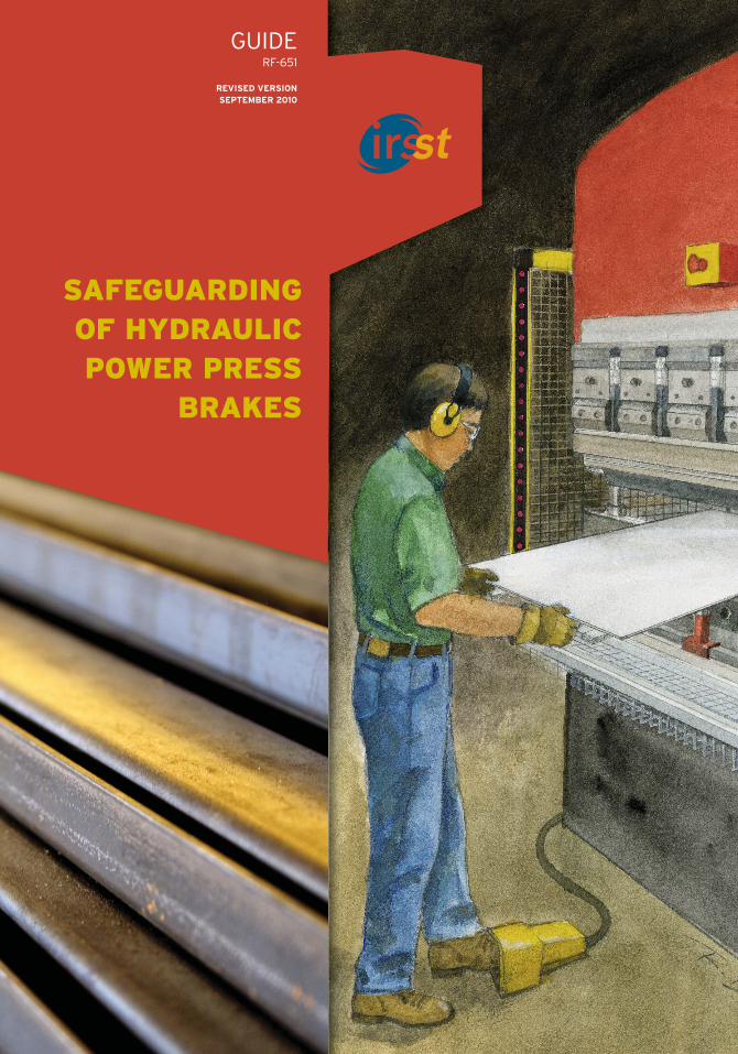
SAFEGUARDING OF HYDRAULICPOWER PRESS
BRAKES

GUIDERF-634
REVISED VERSIONSEPTEMBER 2010
SAFEGUARDING OF HYDRAULIC POWER
PRESS BRAKES
Page 18 of this document was corrected in September 2010.
All IRSST documents and related updates,if any, are available on IRSST’s Web site.
AuthorsDamien Burlet-Vienney, Sabrina Jocelyn and Renaud Daigle, IRSSTSerge Massé, Sécurité-Machines S. Massé
CoordinationLaurent Gratton and Marie-France d’Amours, Knowledge Transfer and Partner Relations Department, IRSST
CollaborationMarjolaine Thibeault, Communications Division, IRSST
AcknowledgementsWe want to thank Guillaume Lemieux and Yuvin Chinniah for their research on the safeguarding of hydraulic power press brakes as well as the members of the follow-up committee who participated in the production of thisdocument: Tony Venditti and Waguih Geadah, Association sectorielle fabrication d’équipement de transport et demachines; Guillaume Côté and Serge Simoneau, Association paritaire pour la santé et la sécurité du travail Secteurfabrication de produits en métal et de produits électriques et des industries de l’habillement; and Denis Leblanc,CSST.We also want to thank the companies Venmar Ventilation Inc. and Bombardier Aerospace that did not hesitate to share their invaluable experience on the safeguarding of hydraulic power press brakes with the IRSST. Finally, we want to acknowledge the help of Mathieu Billette and Christophe Guignolet, integrators of safety devices on hydraulic power press brakes.
Legal deposit Bibliothèque et archives nationalesSeptember 2010ISBN: 978-2-89631-499-7 (PDF)ISSN: 0820-8395
IRSST - Institut de recherche Robert-Sauvé en santé et en sécurité du travail505 de Maisonneuve Blvd. WestMontréal (Québec) H3A 3C2
Telephone: 514 288-1551Fax: 514 288-7636www.irsst.qc.ca
SAFEGUARDING OF HYDRAULICPOWER PRESSBRAKES
SAFEGUARDING OF HYDRAULICPOWER PRESS
BRAKES
Table of contents 1
TABLE OF CONTENTS
1. Preamble ..............................................................................................................................3
2. Knowing your hydraulic power press brake ............................................................5
3. Production variables are determining factors ......................................................8
4. Safeguarding your hydraulic power press brake: choices and compromises ..........................................................................................10
A. Safeguarding the front zone ..................................................................................10Opening reduced to 6 mm (Intrinsic prevention) ............................................................11Safety light curtain (Protective device for everyone located in the front zone) ................12Laser beam device (Protective device for persons nearby)..............................................16Two-hand control device (Protective device for the sole person using it) ........................20
B. Safeguarding of rear and side zones ......................................................................22Electro-sensitive devices ............................................................................................22Movable guard with interlocking device ........................................................................23Fixed guard ................................................................................................................23
5. Complementary means for risk reduction ............................................................24
6. Adapted solutionsA. Use of the opening reduced to 6 mm ....................................................................27B. Use of an obliquely positioned safety light curtain ..............................................28C. Use of two safety light curtains on the same press ..............................................29
7. References........................................................................................................................30
8. Appendices ......................................................................................................................31A. Safety distance for safety light curtains and two-hand control device
on a hydraulic power press brake ..........................................................................31B. Stopping distance for laser beams ........................................................................31C. Reliability of the safety-related control system....................................................32D. Reliability of the safety-related hydraulic system ................................................32
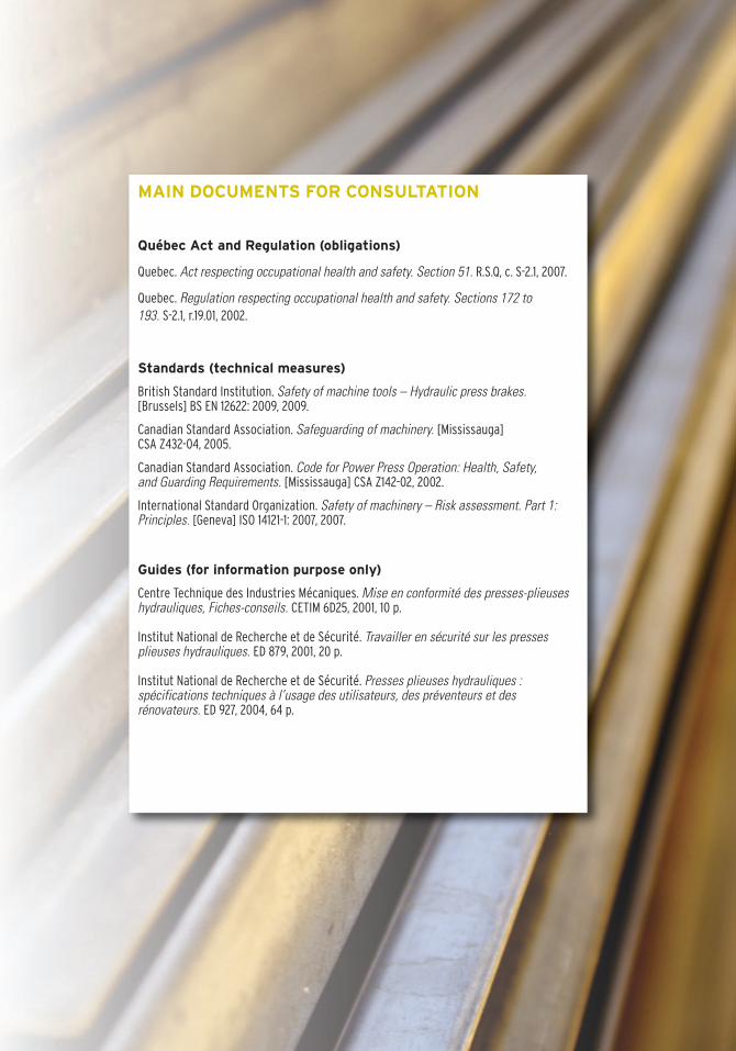
MAIN DOCUMENTS FOR CONSULTATION
Québec Act and Regulation (obligations)
Quebec. Act respecting occupational health and safety. Section 51. R.S.Q, c. S-2.1, 2007.
Quebec. Regulation respecting occupational health and safety. Sections 172 to 193. S-2.1, r.19.01, 2002.
Standards (technical measures)
British Standard Institution. Safety of machine tools – Hydraulic press brakes. [Brussels] BS EN 12622: 2009, 2009.
Canadian Standard Association. Safeguarding of machinery. [Mississauga] CSA Z432-04, 2005.
Canadian Standard Association. Code for Power Press Operation: Health, Safety, and Guarding Requirements. [Mississauga] CSA Z142-02, 2002.
International Standard Organization. Safety of machinery – Risk assessment. Part 1:Principles. [Geneva] ISO 14121-1: 2007, 2007.
Guides (for information purpose only)
Centre Technique des Industries Mécaniques. Mise en conformité des presses-plieuseshydrauliques, Fiches-conseils. CETIM 6D25, 2001, 10 p.
Institut National de Recherche et de Sécurité. Travailler en sécurité sur les pressesplieuses hydrauliques. ED 879, 2001, 20 p.
Institut National de Recherche et de Sécurité. Presses plieuses hydrauliques : spécifications techniques à l’usage des utilisateurs, des préventeurs et des rénovateurs. ED 927, 2004, 64 p.
PREAMBLE
1.
Logical structure of the guide
1. Preamble 3
Objective
The objective of this document is to inform companiesabout the means available for safeguarding hydraulicpower press brakes, while emphasizing the two most recent solutions: the safety light curtain and the laserbeam device.
Targeted users
This document is aimed at everyone involved in the decision-making process relating to the safeguarding ofhydraulic power press brakes: engineers, company owners,CSST inspectors, etc. As a corollary, users of the documentmust have knowledge about hydraulic power press brakesin general, and about their own presses in particular.
Prerequisites
The protective devices mentioned in this document (safetylight curtain, laser beam, two-hand control) are based onthe ram’s stopping capacity. It is therefore essential thatthis stopping capacity be known in terms of reliability and repeatability before considering using the devicesmentioned.
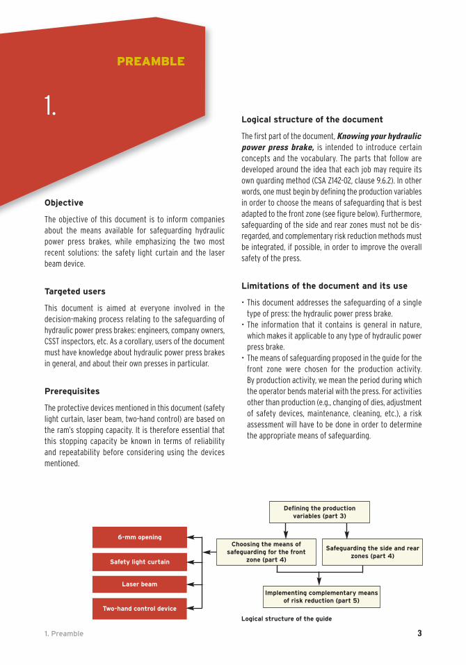
Logical structure of the document
The first part of the document, Knowing your hydraulicpower press brake, is intended to introduce certain concepts and the vocabulary. The parts that follow are developed around the idea that each job may require itsown guarding method (CSA Z142-02, clause 9.6.2). In otherwords, one must begin by defining the production variablesin order to choose the means of safeguarding that is bestadapted to the front zone (see figure below). Furthermore,safeguarding of the side and rear zones must not be dis-regarded, and complementary risk reduction methods mustbe integrated, if possible, in order to improve the overallsafety of the press.
Limitations of the document and its use
• This document addresses the safeguarding of a singletype of press: the hydraulic power press brake.
• The information that it contains is general in nature,which makes it applicable to any type of hydraulic powerpress brake.
• The means of safeguarding proposed in the guide for thefront zone were chosen for the production activity. By production activity, we mean the period during whichthe operator bends material with the press. For activitiesother than production (e.g., changing of dies, adjustmentof safety devices, maintenance, cleaning, etc.), a risk assessment will have to be done in order to determinethe appropriate means of safeguarding.
6-mm opening
Safety light curtain
Laser beam
Two-hand control device
Implementing complementary meansof risk reduction (part 5)
Defining the production variables (part 3)
Choosing the means of safeguarding for the front
zone (part 4)
Safeguarding the side and rearzones (part 4)

2. Knowing your hydraulic power press brake 5
KNOWING YOUR HYDRAULIC
POWER PRESS BRAKE
2.
5
Front 1
10
2
4
4
11
8
7
6
3
Rear
10
9
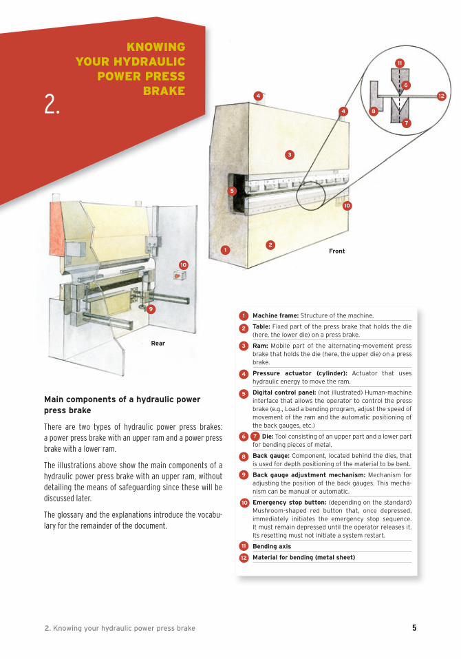
Main components of a hydraulic powerpress brake
There are two types of hydraulic power press brakes: a power press brake with an upper ram and a power pressbrake with a lower ram.
The illustrations above show the main components of a hydraulic power press brake with an upper ram, withoutdetailing the means of safeguarding since these will be discussed later.
The glossary and the explanations introduce the vocabu-lary for the remainder of the document.
12
1 Machine frame: Structure of the machine.
2 Table: Fixed part of the press brake that holds the die(here, the lower die) on a press brake.
3 Ram: Mobile part of the alternating-movement pressbrake that holds the die (here, the upper die) on a pressbrake.
4 Pressure actuator (cylinder): Actuator that uses hydraulic energy to move the ram.
5 Digital control panel: (not illustrated) Human-machineinterface that allows the operator to control the pressbrake (e.g., Load a bending program, adjust the speed ofmovement of the ram and the automatic positioning ofthe back gauges, etc.)
Die: Tool consisting of an upper part and a lower partfor bending pieces of metal.
8 Back gauge: Component, located behind the dies, thatis used for depth positioning of the material to be bent.
9 Back gauge adjustment mechanism: Mechanism foradjusting the position of the back gauges. This mecha-nism can be manual or automatic.
10 Emergency stop button: (depending on the standard)Mushroom-shaped red button that, once depressed, immediately initiates the emergency stop sequence. It must remain depressed until the operator releases it.Its resetting must not initiate a system restart.
11 Bending axis
12 Material for bending (metal sheet)
1
2
3
4
6
5
7
8
9
10
11
12
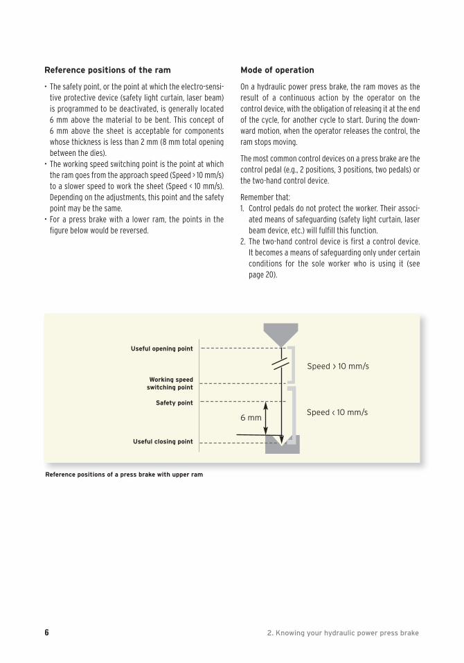
Reference positions of a press brake with upper ram
Useful opening point
Working speedswitching point
Safety point
Useful closing point
Speed › 10 mm/s
Speed ‹ 10 mm/s
]6 mm
6 2. Knowing your hydraulic power press brake
Reference positions of the ram
• The safety point, or the point at which the electro-sensi-tive protective device (safety light curtain, laser beam)is programmed to be deactivated, is generally located 6 mm above the material to be bent. This concept of 6 mm above the sheet is acceptable for componentswhose thickness is less than 2 mm (8 mm total openingbetween the dies).
• The working speed switching point is the point at whichthe ram goes from the approach speed (Speed > 10 mm/s)to a slower speed to work the sheet (Speed < 10 mm/s).Depending on the adjustments, this point and the safetypoint may be the same.
• For a press brake with a lower ram, the points in the figure below would be reversed.
Mode of operation
On a hydraulic power press brake, the ram moves as theresult of a continuous action by the operator on the control device, with the obligation of releasing it at the endof the cycle, for another cycle to start. During the down-ward motion, when the operator releases the control, theram stops moving.
The most common control devices on a press brake are thecontrol pedal (e.g., 2 positions, 3 positions, two pedals) orthe two-hand control device.
Remember that: 1. Control pedals do not protect the worker. Their associ-
ated means of safeguarding (safety light curtain, laserbeam device, etc.) will fulfill this function.
2. The two-hand control device is first a control device. It becomes a means of safeguarding only under certainconditions for the sole worker who is using it (see page 20).
]
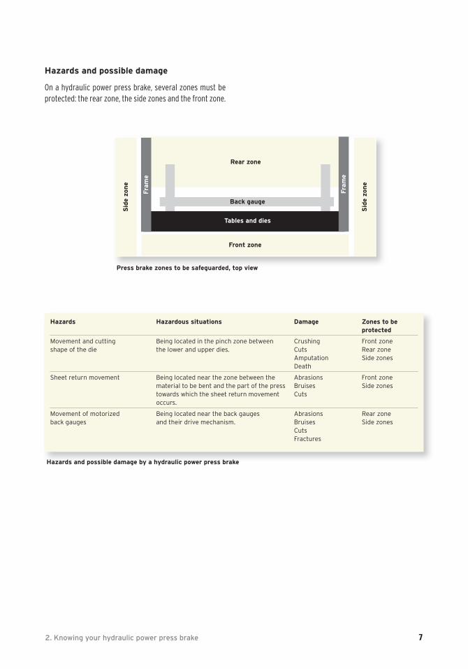
Hazards and possible damage
On a hydraulic power press brake, several zones must beprotected: the rear zone, the side zones and the front zone.
2. Knowing your hydraulic power press brake 7
Hazards Hazardous situations Damage Zones to be protected
Movement and cutting Being located in the pinch zone between Crushing Front zoneshape of the die the lower and upper dies. Cuts Rear zone
Amputation Side zonesDeath
Sheet return movement Being located near the zone between the Abrasions Front zonematerial to be bent and the part of the press Bruises Side zonestowards which the sheet return movement Cutsoccurs.
Movement of motorized Being located near the back gauges Abrasions Rear zoneback gauges and their drive mechanism. Bruises Side zones
Cuts Fractures
Hazards and possible damage by a hydraulic power press brake
Press brake zones to be safeguarded, top view
Rear zone
Back gauge
Tables and dies
Front zone
Sid
e zo
ne
Fra
me
Sid
e zo
ne
Fra
me
8 3. Production variables are determining factors
PRODUCTION VARIABLESARE DETERMINING
FACTORS
Each job may require its own guarding method (CSA Z142-02, clause 9.6.2).
There is no single solution for safeguard-ing a press brake; the best-adapted meansof safeguarding will depend on how thepress brake is used.
Therefore, the first step before anything else is to definethe production variables associated with the press brakethat have a direct impact on the choice of the future meansof safeguarding. For each press, the questions to ask are:
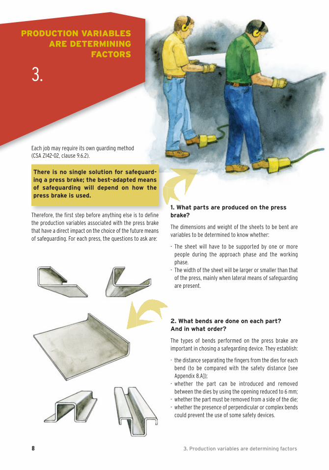
1. What parts are produced on the pressbrake?
The dimensions and weight of the sheets to be bent are variables to be determined to know whether:
- The sheet will have to be supported by one or more people during the approach phase and the workingphase.
- The width of the sheet will be larger or smaller than thatof the press, mainly when lateral means of safeguardingare present.
2. What bends are done on each part? And in what order?
The types of bends performed on the press brake are important in chosing a safegarding device. They establish:
- the distance separating the fingers from the dies for eachbend (to be compared with the safety distance [see Appendix 8.A]);
- whether the part can be introduced and removed between the dies by using the opening reduced to 6 mm;
- whether the part must be removed from a side of the die;- whether the presence of perpendicular or complex bends
could prevent the use of some safety devices.
3.
3. Production variables are determining factors 9
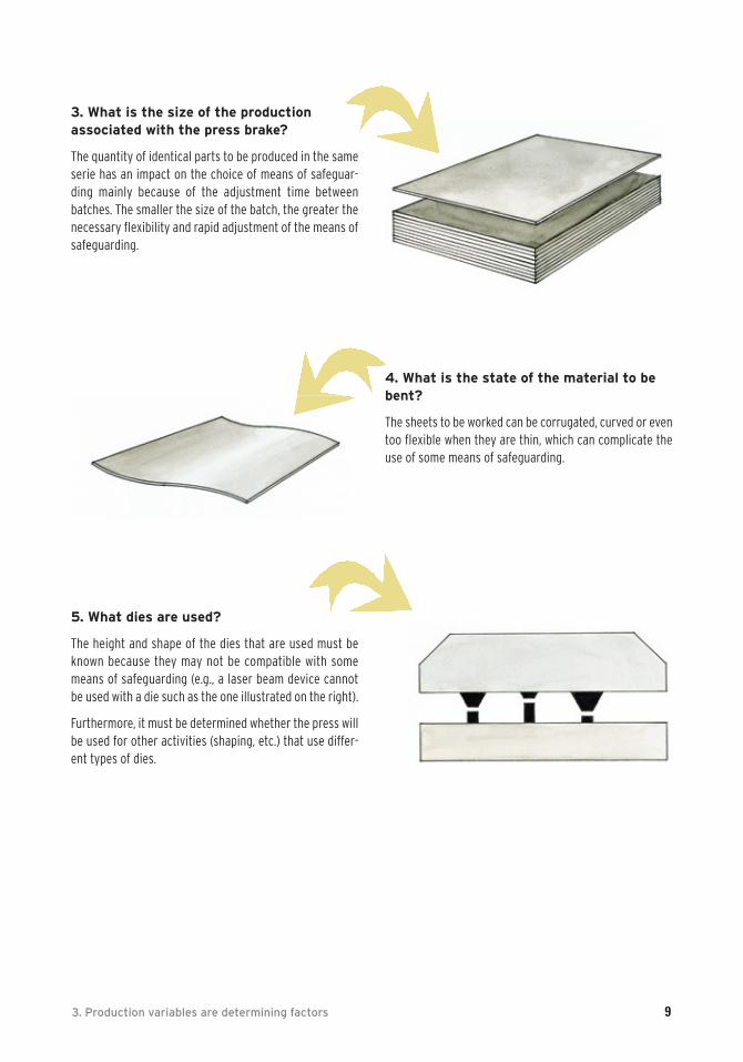
3. What is the size of the production associated with the press brake?
The quantity of identical parts to be produced in the sameserie has an impact on the choice of means of safeguar-ding mainly because of the adjustment time between batches. The smaller the size of the batch, the greater the necessary flexibility and rapid adjustment of the means ofsafeguarding.
5. What dies are used?
The height and shape of the dies that are used must beknown because they may not be compatible with somemeans of safeguarding (e.g., a laser beam device cannotbe used with a die such as the one illustrated on the right).
Furthermore, it must be determined whether the press willbe used for other activities (shaping, etc.) that use differ-ent types of dies.
4. What is the state of the material to bebent?
The sheets to be worked can be corrugated, curved or eventoo flexible when they are thin, which can complicate theuse of some means of safeguarding.
SUGGESTION FOR A PROCEDURE
1. Survey
• Of all parts produced on the press brakes.• Of all the bends on each of the parts.• Of the bend sequence for each part to be produced.• Of the distance of the fingers from the dies for each bend in each part.
2. Classification of partsThe parts to be produced with the same characteristics must be grouped together. For example:
• Parts that require that fingers be very close to the dies in order to put them between the dies or support themduring bending.
• Parts that require handling by more than one person (dimensions, stiffness, weight, etc.).• Thick parts.• Parts that can be produced in large or small lots.• Parts that will require removal from the side of the die after the bend is executed.
3. Measurements and calculations of stopping times and distances of hydraulic power press brakes to besafeguarded (see appendices)
4. Standardization of the height of the dies in order to simplify safeguarding of the press brake (see part 5)
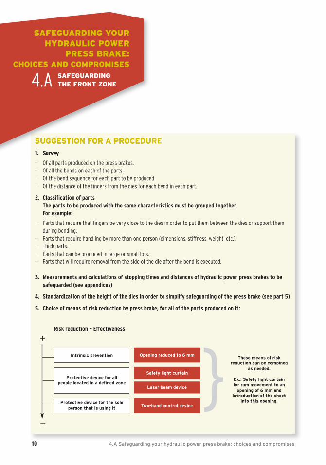
5. Choice of means of risk reduction by press brake, for all of the parts produced on it:
10 4.A Safeguarding your hydraulic power press brake: choices and compromises
SAFEGUARDING YOUR HYDRAULIC POWER
PRESS BRAKE: CHOICES AND COMPROMISES
4.A SAFEGUARDING THE FRONT ZONE
+
_
Opening reduced to 6 mm
Safety light curtain
Laser beam device
Two-hand control device
These means of risk reduction can be combined
as needed.
Ex.: Safety light curtain for ram movement to an
opening of 6 mm and introduction of the sheet
into this opening.}Protective device for all people located in a defined zone
Protective device for the sole person that is using it
Intrinsic prevention
Risk reduction – Effectiveness
OPENING REDUCED TO 6 MM (Intrinsic prevention)
Description
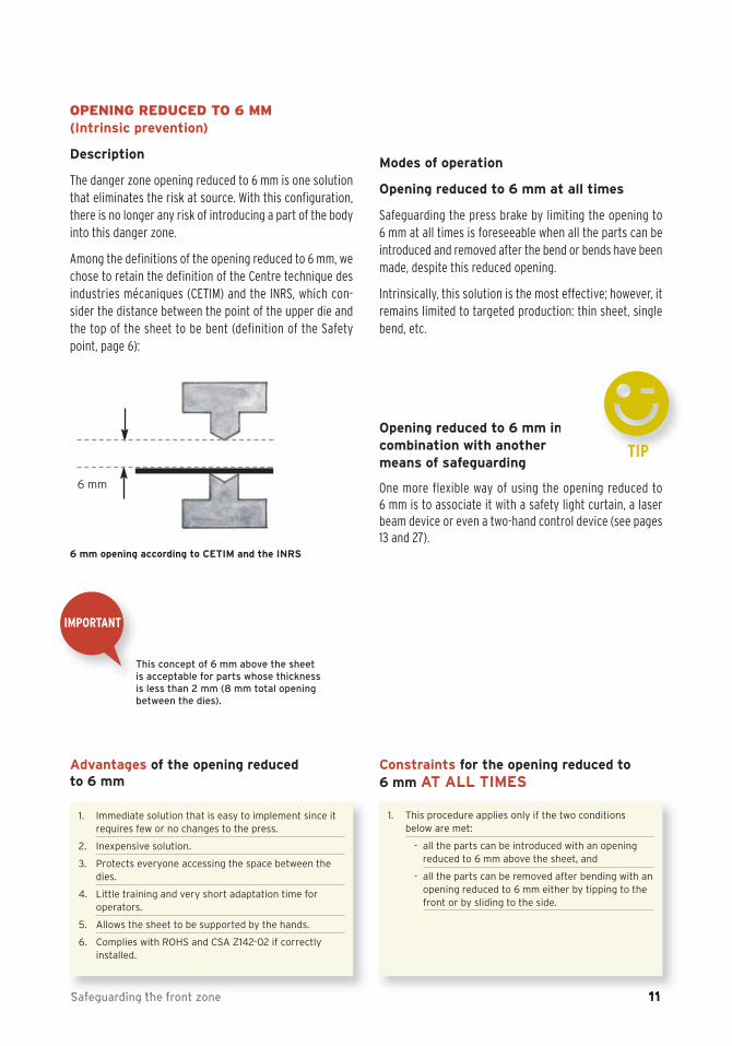
The danger zone opening reduced to 6 mm is one solutionthat eliminates the risk at source. With this configuration,there is no longer any risk of introducing a part of the bodyinto this danger zone.
Among the definitions of the opening reduced to 6 mm, wechose to retain the definition of the Centre technique desindustries mécaniques (CETIM) and the INRS, which con-sider the distance between the point of the upper die andthe top of the sheet to be bent (definition of the Safetypoint, page 6):
Modes of operation
Opening reduced to 6 mm at all times
Safeguarding the press brake by limiting the opening to 6 mm at all times is foreseeable when all the parts can beintroduced and removed after the bend or bends have beenmade, despite this reduced opening.
Intrinsically, this solution is the most effective; however, itremains limited to targeted production: thin sheet, singlebend, etc.
Opening reduced to 6 mm in combination with another means of safeguarding
One more flexible way of using the opening reduced to 6 mm is to associate it with a safety light curtain, a laserbeam device or even a two-hand control device (see pages13 and 27).
Safeguarding the front zone 11
6 mm
dIMPORTANT
6 mm opening according to CETIM and the INRS
This concept of 6 mm above the sheetis acceptable for parts whose thicknessis less than 2 mm (8 mm total openingbetween the dies).
0
1. Immediate solution that is easy to implement since itrequires few or no changes to the press.
2. Inexpensive solution.
3. Protects everyone accessing the space between thedies.
4. Little training and very short adaptation time for operators.
5. Allows the sheet to be supported by the hands.
6. Complies with ROHS and CSA Z142-02 if correctly installed.
Advantages of the opening reduced to 6 mm
1. This procedure applies only if the two conditionsbelow are met:
- all the parts can be introduced with an opening reduced to 6 mm above the sheet, and
- all the parts can be removed after bending with anopening reduced to 6 mm either by tipping to thefront or by sliding to the side.
Constraints for the opening reduced to 6 mm AT ALL TIMES
TIP
12 4.A Safeguarding your hydraulic power press brake: choices and compromises
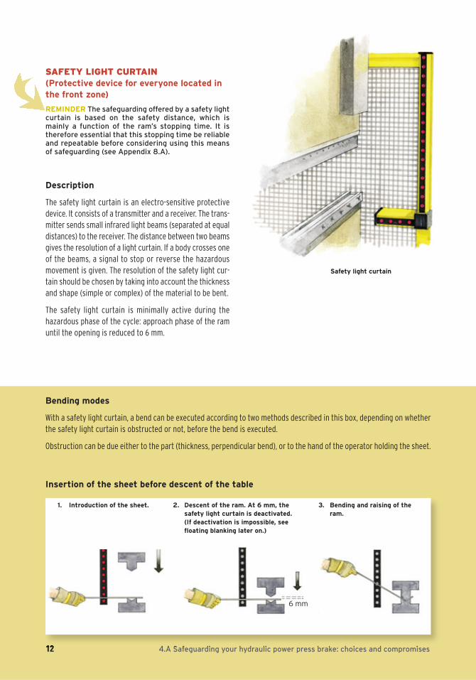
SAFETY LIGHT CURTAIN (Protective device for everyone located inthe front zone)
REMINDER The safeguarding offered by a safety lightcurtain is based on the safety distance, which ismainly a function of the ram’s stopping time. It istherefore essential that this stopping time be reliableand repeatable before considering using this meansof safeguarding (see Appendix 8.A).
Description
The safety light curtain is an electro-sensitive protectivedevice. It consists of a transmitter and a receiver. The trans-mitter sends small infrared light beams (separated at equaldistances) to the receiver. The distance between two beamsgives the resolution of a light curtain. If a body crosses oneof the beams, a signal to stop or reverse the hazardousmovement is given. The resolution of the safety light cur-tain should be chosen by taking into account the thicknessand shape (simple or complex) of the material to be bent.
The safety light curtain is minimally active during the hazardous phase of the cycle: approach phase of the ramuntil the opening is reduced to 6 mm.
Safety light curtain
1. Introduction of the sheet. 2. Descent of the ram. At 6 mm, thesafety light curtain is deactivated.(If deactivation is impossible, seefloating blanking later on.)
3. Bending and raising of theram.
6 mm
Bending modes
With a safety light curtain, a bend can be executed according to two methods described in this box, depending on whetherthe safety light curtain is obstructed or not, before the bend is executed.
Obstruction can be due either to the part (thickness, perpendicular bend), or to the hand of the operator holding the sheet.
Insertion of the sheet before descent of the table
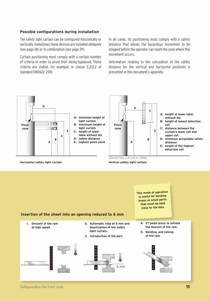
Possible configurations during installation
The safety light curtain can be configured horizontally orvertically. Sometimes these devices are installed obliquely(see page 28) or in combination (see page 29).
Curtain positioning must comply with a certain number of criteria in order to avoid their being bypassed. These criteria are stated, for example, in clause 5.3.12.2 of standard EN12622: 2001.
In all cases, its positioning must comply with a safety distance that allows the hazardous movement to bestopped before the operator can reach the zone where thismovement occurs.
Information relating to the calculation of the safety distance for the vertical and horizontal positions is presented in this document’s appendix.
Safeguarding the front zone 13
Horizontal safety light curtain
Pinch zone
AB
C
D
E
A: minimum height oflight curtain
B: maximum height oflight curtain
C: height of lowertable without die
D: safety distanceE: highest pinch point
Vertical safety light curtain
Pinch zone
AB
CD
E
A: height of lower table without die
B: height of lowest detectioncell
C: distance between the curtain’s lower cell andupper cell
D: minimum acceptable safetydistance
E: height of the highest detection cell
(Source: Ngô, A.D. and al., 1998)
1. Descent of the ram at high speed.
This mode of operation
is useful for bending
boxes or small parts
that must be held
close to the dies.
4. 2nd pedal press to initiate the descent of the ram.
5. Bending, and raising of the ram.
6 mm
Insertion of the sheet into an opening reduced to 6 mm
2. Automatic stop at 6 mm anddeactivation of the safetylight curtain.
3. Introduction of the part.
14 4.A Safeguarding your hydraulic power press brake: choices and compromises
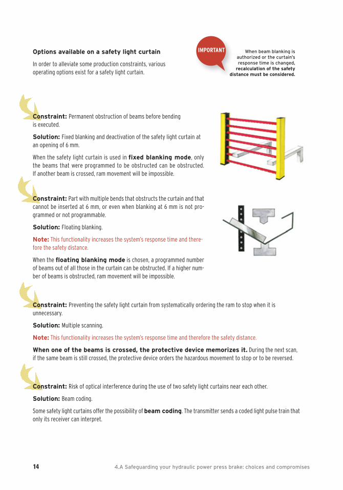
Options available on a safety light curtain
In order to alleviate some production constraints, variousoperating options exist for a safety light curtain.
dIMPORTANT When beam blanking is
authorized or the curtain’s response time is changed,
recalculation of the safetydistance must be considered.
Constraint: Permanent obstruction of beams before bending is executed.
Solution: Fixed blanking and deactivation of the safety light curtain atan opening of 6 mm.
When the safety light curtain is used in fixed blanking mode, only the beams that were programmed to be obstructed can be obstructed. If another beam is crossed, ram movement will be impossible.
Constraint: Part with multiple bends that obstructs the curtain and thatcannot be inserted at 6 mm, or even when blanking at 6 mm is not pro-grammed or not programmable.
Solution: Floating blanking.
Note: This functionality increases the system’s response time and there-fore the safety distance.
When the floating blanking mode is chosen, a programmed numberof beams out of all those in the curtain can be obstructed. If a higher num-ber of beams is obstructed, ram movement will be impossible.
Constraint: Preventing the safety light curtain from systematically ordering the ram to stop when it is unnecessary.
Solution: Multiple scanning.
Note: This functionality increases the system’s response time and therefore the safety distance.
When one of the beams is crossed, the protective device memorizes it. During the next scan,if the same beam is still crossed, the protective device orders the hazardous movement to stop or to be reversed.
Constraint: Risk of optical interference during the use of two safety light curtains near each other.
Solution: Beam coding.
Some safety light curtains offer the possibility of beam coding. The transmitter sends a coded light pulse train thatonly its receiver can interpret.
Safeguarding the front zone 15
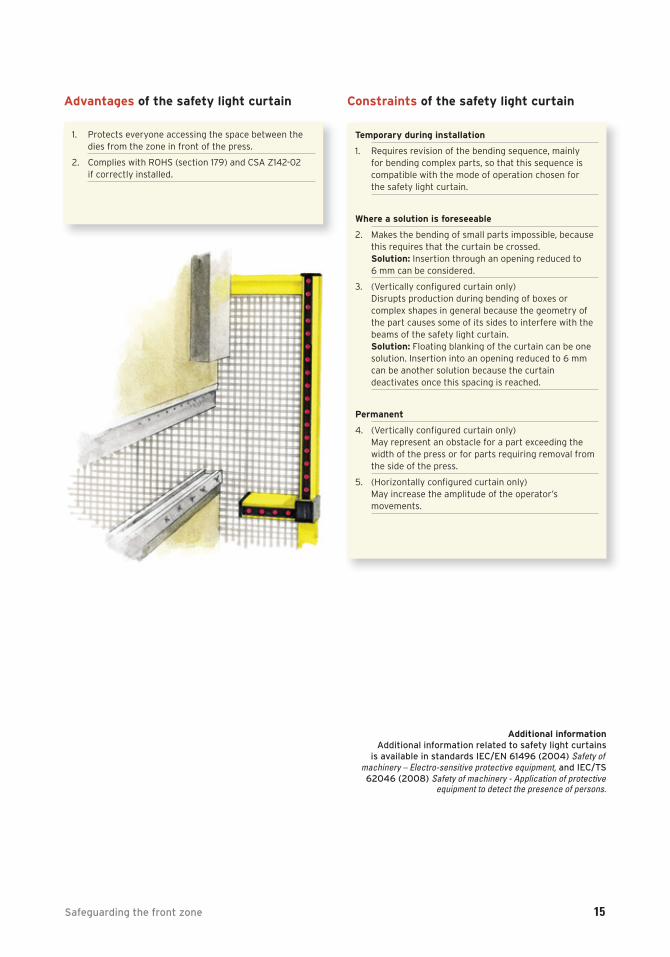
1. Protects everyone accessing the space between thedies from the zone in front of the press.
2. Complies with ROHS (section 179) and CSA Z142-02 if correctly installed.
Advantages of the safety light curtain
Temporary during installation
1. Requires revision of the bending sequence, mainly for bending complex parts, so that this sequence iscompatible with the mode of operation chosen for the safety light curtain.
Where a solution is foreseeable
2. Makes the bending of small parts impossible, becausethis requires that the curtain be crossed. Solution: Insertion through an opening reduced to 6 mm can be considered.
3. (Vertically configured curtain only) Disrupts production during bending of boxes or complex shapes in general because the geometry ofthe part causes some of its sides to interfere with thebeams of the safety light curtain. Solution: Floating blanking of the curtain can be onesolution. Insertion into an opening reduced to 6 mmcan be another solution because the curtain deactivates once this spacing is reached.
Permanent
4. (Vertically configured curtain only) May represent an obstacle for a part exceeding thewidth of the press or for parts requiring removal fromthe side of the press.
5. (Horizontally configured curtain only) May increase the amplitude of the operator’smovements.
Constraints of the safety light curtain
Additional informationAdditional information related to safety light curtains
is available in standards IEC/EN 61496 (2004) Safety of machinery – Electro-sensitive protective equipment, and IEC/TS62046 (2008) Safety of machinery - Application of protective
equipment to detect the presence of persons.

16 4.A Safeguarding your hydraulic power press brake: choices and compromises
LASER BEAM DEVICE (Protective device for persons nearby)
REMINDER The safeguarding offered by a laser beamdevice is based on the ram’s stopping distance. It istherefore essential that this stopping distance beknown, reliable and repeatable before consideringusing this means of safeguarding (see Appendix 8.B).
Description
Laser beam devices or camera systems are electro-sensitive devices that use a LASER-type light source in theinfrared spectrum. They detect any intrusion between theupper die and the lower die, until the laser beam is 6 mmfrom the sheet. At less than 6 mm, the laser beam deviceis deactivated.
The laser beam device is attached to the upper table andis height adjustable. For positioning in relation to the die onthe ram, the following must be taken into account:
- the distance between the highest laser beam and thepoint of the upper die, which must not allow a finger toenter without it being detected,
- the ram’s stopping distance.
Furthermore, the associated control device for closing thedies must be a three-position pedal control [OFF/ON/Emer-gency stop]. This pedal must be maintained in an interme-diate position to allow the dies to close.
Modes of operation
Detection under the upper die is done in three zones: front(zone 1), central (zone 2) and rear (zone 3). The modes ofoperation available are:
1. Regular mode in which the three detection zones are active. This figure case is possible, for example, duringa first bend. The operator has maximum protection inthis mode.
2. Box mode, in which the front zone is deactivated to avoidstopping due to a perpendicular bend.
3. Box and back gauges mode in which only the centralzone is active. The front and rear zones are deactivatedto avoid stopping due to a perpendicular bend and thepresence of the back gauges as with a bend near theedge.
The last two modes should be used only when necessarybecause the press is being operated with reduced safety.
Products available
Each manufacturer has developed his own method for protecting the operator: protection volume, vertical lines,horizontal lines, etc. In 2008, five manufacturers were identified, and their proposed products generally use thethree modes of operation explained above, and can be usedin category 4 safety circuits according to ISO 13849-1: 2006.
Laser beam device on a hydraulicpower press brake (Source: ASPHME)
Upperdie
Lower die
Front1 2 3
Detection zones of a laser beam device
Zones
Safeguarding the front zone 17
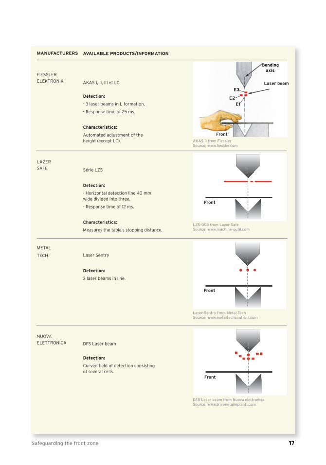
MANUFACTURERS
FIESSLER
ELEKTRONIK
LAZER
SAFE
METAL
TECH
NUOVA
ELETTRONICA
AVAILABLE PRODUCTS/INFORMATION
AKAS I, II, III et LC
Detection:
- 3 laser beams in L formation.
- Response time of 25 ms.
Characteristics:
Automated adjustment of the height (except LC).
Série LZS
Detection:
- Horizontal detection line 40 mm wide divided into three.
- Response time of 12 ms.
Characteristics:
Measures the table’s stopping distance.
Laser Sentry
Detection:
3 laser beams in line.
DFS Laser beam
Detection:
Curved field of detection consisting of several cells.
Bendingaxis
Laser beam
Front
E3
E2E1
AKAS II from Fiessler Source: www.fiessler.com
Front
LZS-003 from Lazer Safe Source: www.machine-outil.com
Front
Laser Sentry from Metal TechSource: www.metaltechcontrols.com
DFS Laser beam from Nuova elettronicaSource: www.trivenetaimpianti.com
Front
18 4.A Safeguarding your hydraulic power press brake: choices and compromises
MANUFACTURERS
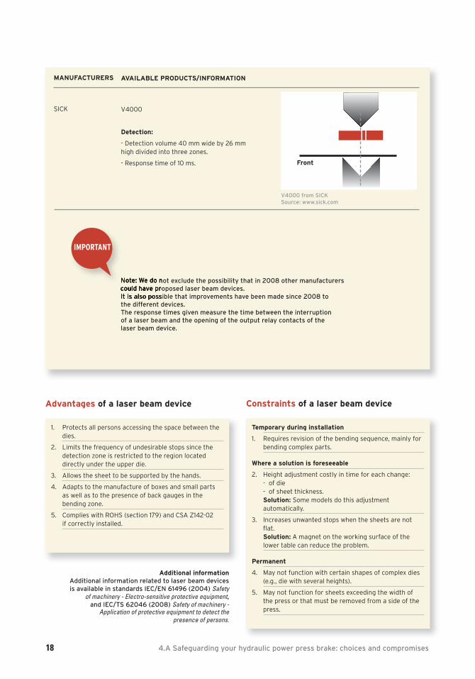
SICK
AVAILABLE PRODUCTS/INFORMATION
V4000
Detection:
- Detection volume 40 mm wide by 26 mm high divided into three zones.
- Response time of 10 ms. Front
V4000 from SICK Source: www.sick.com
1. Protects all persons accessing the space between thedies.
2. Limits the frequency of undesirable stops since thedetection zone is restricted to the region located directly under the upper die.
3. Allows the sheet to be supported by the hands.
4. Adapts to the manufacture of boxes and small partsas well as to the presence of back gauges in the bending zone.
5. Complies with ROHS (section 179) and CSA Z142-02if correctly installed.
Advantages of a laser beam device
Temporary during installation
1. Requires revision of the bending sequence, mainly forbending complex parts.
Where a solution is foreseeable
2. Height adjustment costly in time for each change:- of die- of sheet thickness.Solution: Some models do this adjustment automatically.
3. Increases unwanted stops when the sheets are notflat. Solution: A magnet on the working surface of thelower table can reduce the problem.
Permanent
4. May not function with certain shapes of complex dies(e.g., die with several heights).
5. May not function for sheets exceeding the width ofthe press or that must be removed from a side of thepress.
Constraints of a laser beam device
Additional informationAdditional information related to laser beam devices is available in standards IEC/EN 61496 (2004) Safety
of machinery - Electro-sensitive protective equipment, and IEC/TS 62046 (2008) Safety of machinery -
Application of protective equipment to detect the presence of persons.
Note: We do not exclude the possibility that in 2008 other manufacturers could have proposed laser beam devices. It is also possible that improvements have been made since 2008 to the different devices.The response times given measure the time between the interruption of a laser beam and the opening of the output relay contacts of the laser beam device.
dIMPORTANT
Safeguarding the front zone 19
INTEGRATION OF A LASER BEAM DEVICE OR A SAFETY LIGHT CURTAIN
The installation of a laser beam device or a safety light curtain will require changes to your press brake. To improve yourchances of having a successful integration, several actions must be considered before, during and after this step.
A successful integration and a planned knowledge transfer can optimize production on press brakes.
Actions to consider BEFORE integrating the device
1. Consult the supplier to ensure that the chosen solution is adapted and complies with Québec regulations as wellas with the relevant standards.
2. Make sure that you have the manufacturer’s or the supplier’s technical support.
3. Have in your possession the hydraulic, electrical and mechanical plans for the press brake.
4. Evaluate:- the proper operation of the press brake,- the reliability of the safety-related control system (see Appendix 8.C),- the reliability of the hydraulic circuit (see Appendix 8.D),- the reliability of the electrical circuit,- the ram’s stopping distance and time.
5. Make sure that you have access to the original programs of the press and that someone in the company has therelevant expertise.
6. Ensure compatibility of the electrical signals and encoders between the safeguarding device and the press brakecontrols.
Actions to consider WHEN integrating the device
1. Manage the different modes of operation.
2. Manage the approach and working speeds for the press brakes:- at a single speed,- at a speed varying in relation to the command.
3. Manage, during deactivation of the safeguarding device, the blocking of the press brake at slow speed (< 10 mm/s).
Actions to consider AFTER integrating the device
1. Obtain the electrical and hydraulic plans containing the modifications carried out on the press brake.
2. Receive training on the use of the device and have the user’s manuals in your possession.
3. Perform the safety audits on the operation of the safeguarding device at regular intervals (including tests for theram’s stopping time and distance).
dFOR FURTHERINFORMATION
20 4.A Safeguarding your hydraulic power press brake: choices and compromises
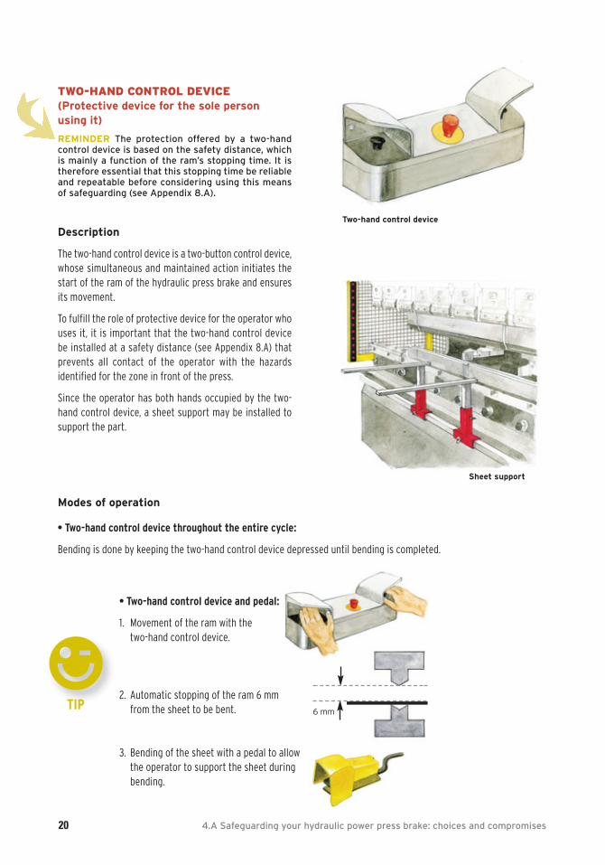
TWO-HAND CONTROL DEVICE (Protective device for the sole personusing it)
REMINDER The protection offered by a two-hand control device is based on the safety distance, whichis mainly a function of the ram’s stopping time. It istherefore essential that this stopping time be reliableand repeatable before considering using this meansof safeguarding (see Appendix 8.A).
Description
The two-hand control device is a two-button control device,whose simultaneous and maintained action initiates thestart of the ram of the hydraulic press brake and ensuresits movement.
To fulfill the role of protective device for the operator whouses it, it is important that the two-hand control device be installed at a safety distance (see Appendix 8.A) thatprevents all contact of the operator with the hazards identified for the zone in front of the press.
Since the operator has both hands occupied by the two-hand control device, a sheet support may be installed tosupport the part.
Two-hand control device
Sheet support
Modes of operation
• Two-hand control device throughout the entire cycle:
Bending is done by keeping the two-hand control device depressed until bending is completed.
0TIP
6 mm
• Two-hand control device and pedal:
1. Movement of the ram with the two-hand control device.
2. Automatic stopping of the ram 6 mm from the sheet to be bent.
3. Bending of the sheet with a pedal to allowthe operator to support the sheet duringbending.
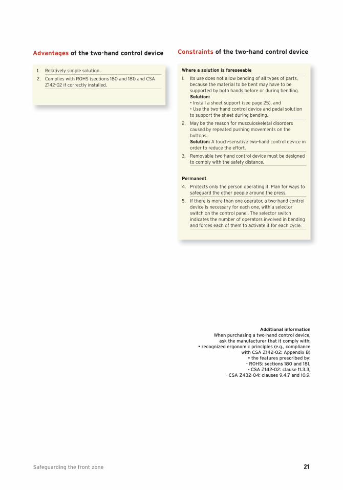
Safeguarding the front zone 21
1. Relatively simple solution.
2. Complies with ROHS (sections 180 and 181) and CSAZ142-02 if correctly installed.
Advantages of the two-hand control device
Where a solution is foreseeable
1. Its use does not allow bending of all types of parts, because the material to be bent may have to be supported by both hands before or during bending.Solution:• Install a sheet support (see page 25), and• Use the two-hand control device and pedal solutionto support the sheet during bending.
2. May be the reason for musculoskeletal disorderscaused by repeated pushing movements on the buttons.Solution: A touch-sensitive two-hand control device inorder to reduce the effort.
3. Removable two-hand control device must be designedto comply with the safety distance.
Permanent
4. Protects only the person operating it. Plan for ways tosafeguard the other people around the press.
5. If there is more than one operator, a two-hand controldevice is necessary for each one, with a selectorswitch on the control panel. The selector switch indicates the number of operators involved in bendingand forces each of them to activate it for each cycle.
Constraints of the two-hand control device
Additional informationWhen purchasing a two-hand control device,
ask the manufacturer that it comply with:• recognized ergonomic principles (e.g., compliance
with CSA Z142-02: Appendix B)• the features prescribed by:
- ROHS: sections 180 and 181, - CSA Z142-02: clause 11.3.3,
- CSA Z432-04: clauses 9.4.7 and 10.9.

SAFEGUARDING YOUR HYDRAULIC POWER
PRESS BRAKE: CHOICES AND COMPROMISES
4.B SAFEGUARDING OF REAR AND SIDE ZONES
22 4.B Safeguarding your hydraulic power press brake: choices and compromises
REMINDER Rear and side zones are also zones tobe safeguarded. These zones must therefore besafeguarded during production, while remainingpotentially accessible for some specific opera-tions.
ELECTRO-SENSITIVE DEVICESDefinition (ISO 12100 : 2003)
Equipment designed to detect people or parts of their bodies and to send a signal to the control system intendedto reduce the risk to which the detected people are exposed. The signal can be triggered when a person or apart of his body goes beyond a pre-established limit – forexample, when the person enters a danger zone – (detec-tion of the crossing of a boundary) or while a person is detected in a previously delimited zone (presence detec-tion), or in both cases. (Free translation of French version)
1. Electro-sensitive devices that can ensure safeguardingof the rear zone are, for example:
- a safety light curtain,- a pressure-sensitive mat,- a laser scanner,- several mono-beams,- a combination of these devices.2.The safety light curtain is the electro-sensitive device
that can ensure safeguarding of the side zones.
N.B. These devices must comply with the requirements related to the safety distance principle stated in Appendix8.A.
Additional information- CSA Z142-02 clauses 11.3.2., 11.3.5, 11.3.6, 11.3.8, Code for
Power Press Operation: Health, Safety, and Guarding Requirements.
- IEC/EN 61496-1 and -2 (2004) Safety of machinery -Electro-sensitive protective equipment.
Mono-beams for the zone behind
the press brake
MOVABLE GUARD WITH INTERLOCKINGDEVICE
Definition (CSA Z142-02)
Movable guard associated with an interlocking device, insuch a way that :
- the hazardous press functions “covered” by the guardcannot operate until the guard is closed;
- if the guard is opened while hazardous press functionsare operating, a stop instruction is given; and
- when the guard is closed, the hazardous press functions“covered” by the guard can operate, but the closure ofthe guard does not by itself initiate their operation.
Additional information- CSA Z142-02 clauses 11.1.3.4.1 and 11.3.1, Code for Power
Press Operation: Health, Safety, and - ISO 14119: 1998, Safety of machinery – Interlocking
devices associated with guards – Principles for design and selection.
- ISO 14120: 2002, Safety of machinery – Guards - General requirements for the design and construction of fixed and movable guards.
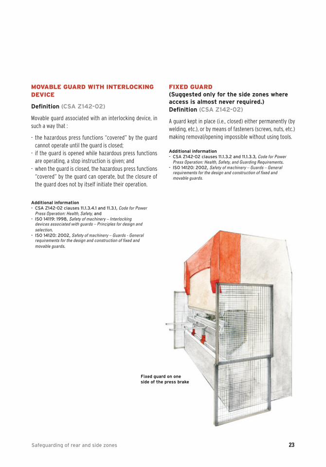
FIXED GUARD (Suggested only for the side zones whereaccess is almost never required.)Definition (CSA Z142-02)
A guard kept in place (i.e., closed) either permanently (bywelding, etc.), or by means of fasteners (screws, nuts, etc.)making removal/opening impossible without using tools.
Additional information- CSA Z142-02 clauses 11.1.3.2 and 11.1.3.3, Code for Power
Press Operation: Health, Safety, and Guarding Requirements.- ISO 14120: 2002, Safety of machinery – Guards – General
requirements for the design and construction of fixed and movable guards.
Fixed guard on one side of the press brake
Safeguarding of rear and side zones 23
24 5. Complementary means for risk reduction
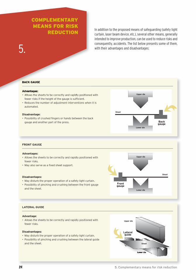
In addition to the proposed means of safeguarding (safety lightcurtain, laser beam device, etc.), several other means, generally intended to improve production, can be used to reduce risks andconsequently, accidents. The list below presents some of them,with their advantages and disadvantages:
BACK GAUGE
Advantages:
• Allows the sheets to be correctly and rapidly positioned with
fewer risks if the height of the gauge is sufficient.
• Reduces the number of adjustment interventions when it is
automated.
Disadvantage:
• Possibility of crushed fingers or hands between the back
gauge and another part of the press.
Upper die
Lower die
Backgauge
Sheet
FRONT GAUGE
Advantages:
• Allows the sheets to be correctly and rapidly positioned with
fewer risks.
• May also serve as a fixed sheet support.
Disadvantages:
• May disturb the proper operation of a safety light curtain.
• Possibility of pinching and crushing between the front gauge
and the sheet.
Upper die
Lower die
Frontgauge
Sheet
LATERAL GUIDE
Advantage:
• Allows the sheets to be correctly and rapidly positioned with
fewer risks.
Disadvantages:
• May disturb the proper operation of a safety light curtain.
• Possibility of pinching and crushing between the lateral guide
and the sheet.
Lower die
COMPLEMENTARYMEANS FOR RISK
REDUCTION
5.
Lateralguide
Upper die
Sheet
5. Complementary means for risk reduction 25
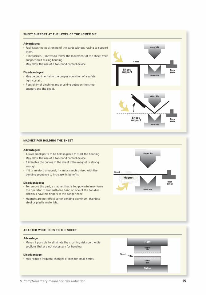
SHEET SUPPORT AT THE LEVEL OF THE LOWER DIE
Advantages:
• Facilitates the positioning of the parts without having to support
them.
• If motorized, it moves to follow the movement of the sheet while
supporting it during bending.
• May allow the use of a two-hand control device.
Disadvantages:
• May be detrimental to the proper operation of a safety
light curtain.
• Possibility of pinching and crushing between the sheet
support and the sheet.
Upper die
Lower die
Backgauge
Sheet
Sheetsupport
Upper die
Lower die
Backgauge
Sheetsupport
MAGNET FOR HOLDING THE SHEET
Advantages:
• Allows small parts to be held in place to start the bending.
• May allow the use of a two-hand control device.
• Eliminates the curves in the sheet if the magnet is strong
enough.
• If it is an electromagnet, it can by synchronized with the
bending sequence to increase its benefits.
Disadvantages: • To remove the part, a magnet that is too powerful may force
the operator to lean with one hand on one of the two diesand thus have his fingers in the danger zone.
• Magnets are not effective for bending aluminum, stainlesssteel or plastic materials.
Upper die
Lower die
Backgauge
Sheet
Magnet
ADAPTED-WIDTH DIES TO THE SHEET
Advantage:
• Makes it possible to eliminate the crushing risks on the die
sections that are not necessary for bending.
Disadvantage:
• May require frequent changes of dies for small series.
Sheet
Ram
Upper die
Lowerdie
Table

26 5. Complementary means for risk reduction
AVOIDING HAZARDOUS BENDING THROUGHPARTS DESIGN
Advantages:
• Eliminates bending that can be dangerous to
perform. (e.g., Bends that create sheet return move-
ment, those that are too close to the edge, etc.).
Note: Consulting press brake operators before
finalizing the design of the part could be one
approach to consider.
• Avoids designing large parts that have to be removed
from the side, and as a result, rendering some means
of safeguarding unusable (safety light curtain, laser
beam device, lateral guards).
PROGRAMMING THE BENDING SEQUENCE
Advantages:
• Makes it possible to avoid situations in which the
opening of the dies is larger than necessary
(thickness of the part + 6 mm) to release the parts.
• Limits the blanking of some or all of the safety device
(e.g., safety light curtain) to make the final bends.
• Makes it possible to avoid parts hanging behind the
dies and therefore the part tipping behind the press.
UNIFORMIZATION OF DIE HEIGHT
Advantages:• Reduces the interventions and adjustment times for
dies.
• May allow several series of parts to be produced without readjusting the safety devices (e.g., laserbeams).
TRAINING OF OPERATORS AND MAINTENANCESTAFF
Advantages:• Allows accidents to be avoided through better
knowledge of hydraulic power press brake operationand of the bending process.
• Helps minimize bypasses if the worker is trained in the operation and use of means of safeguarding.
• Allows personnel to be more efficient in press maintenance and operation.
SPEED REDUCED TO 10 MM/S AND 3-POSITION
PEDAL [OFF/ON/EMERGENCY STOP]
The reduction of the ram’s speed to 10 mm/s and
the use of the 3-position pedal reduce the risk by
increasing the possibility of avoiding harm. • This measure is not a means of safeguarding, but is
instead a means of risk reduction. It therefore doesnot comply with ROHS according to section 182.It is a last resort or temporary measure when it isimpossible to safeguard the press brake in anotherway, or even when the existing safety device must be bypassed.
If this method is permanently installed, there must be proof that it is the only method available for riskreduction.
USE OF A HOIST
Advantages:
• Allows heavy parts to be handled, and also avoids
certain risks of back pain, impacts, crushing, etc.
• May allow fewer operators to be mobilized.
Disadvantage:
• Requires a lot of vigilance if several operators
are working together.
Context
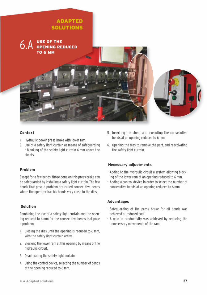
1. Hydraulic power press brake with lower ram.2. Use of a safety light curtain as means of safeguarding
– Blanking of the safety light curtain 6 mm above thesheets.
Problem
Except for a few bends, those done on this press brake canbe safeguarded by installing a safety light curtain. The fewbends that pose a problem are called consecutive bendswhere the operator has his hands very close to the dies.
Solution
Combining the use of a safety light curtain and the open-ing reduced to 6 mm for the consecutive bends that posea problem:
1. Closing the dies until the opening is reduced to 6 mm,with the safety light curtain active.
2. Blocking the lower ram at this opening by means of thehydraulic circuit.
3. Deactivating the safety light curtain.
4. Using the control device, selecting the number of bendsat the opening reduced to 6 mm.
5. Inserting the sheet and executing the consecutivebends at an opening reduced to 6 mm.
6. Opening the dies to remove the part, and reactivatingthe safety light curtain.
Necessary adjustments
- Adding to the hydraulic circuit a system allowing block-ing of the lower ram at an opening reduced to 6 mm.
- Adding a control device in order to select the number ofconsecutive bends at an opening reduced to 6 mm.
Advantages
- Safeguarding of the press brake for all bends wasachieved at reduced cost.
- A gain in productivity was achieved by reducing the unnecessary movements of the ram.
6.A Adapted solutions 27
ADAPTED SOLUTIONS
6.A USE OF THE OPENING REDUCEDTO 6 MM
28 6.B Use of an obliquely positioned safety light curtain
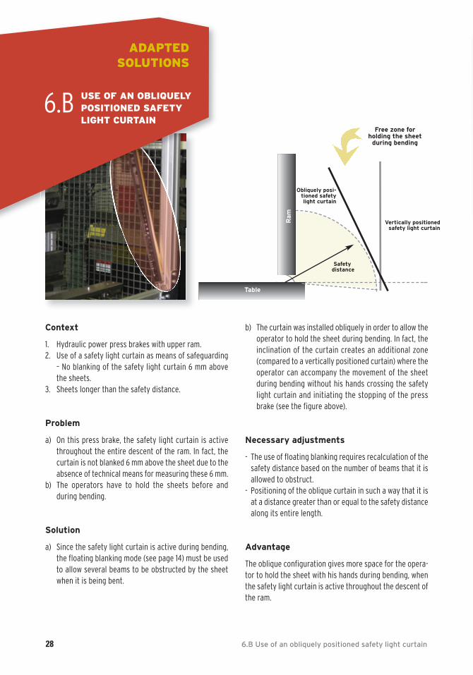
Context
1. Hydraulic power press brakes with upper ram.2. Use of a safety light curtain as means of safeguarding
– No blanking of the safety light curtain 6 mm abovethe sheets.
3. Sheets longer than the safety distance.
Problem
a) On this press brake, the safety light curtain is activethroughout the entire descent of the ram. In fact, thecurtain is not blanked 6 mm above the sheet due to theabsence of technical means for measuring these 6 mm.
b) The operators have to hold the sheets before and during bending.
Solution
a) Since the safety light curtain is active during bending,the floating blanking mode (see page 14) must be usedto allow several beams to be obstructed by the sheetwhen it is being bent.
b) The curtain was installed obliquely in order to allow theoperator to hold the sheet during bending. In fact, theinclination of the curtain creates an additional zone(compared to a vertically positioned curtain) where theoperator can accompany the movement of the sheetduring bending without his hands crossing the safetylight curtain and initiating the stopping of the pressbrake (see the figure above).
Necessary adjustments
- The use of floating blanking requires recalculation of thesafety distance based on the number of beams that it isallowed to obstruct.
- Positioning of the oblique curtain in such a way that it isat a distance greater than or equal to the safety distancealong its entire length.
Advantage
The oblique configuration gives more space for the opera-tor to hold the sheet with his hands during bending, whenthe safety light curtain is active throughout the descent ofthe ram.
ADAPTED SOLUTIONS
6.B
Safetydistance
Free zone forholding the sheet
during bending
Ram
Table
Vertically positionedsafety light curtain
Obliquely posi-tioned safetylight curtain
USE OF AN OBLIQUELY POSITIONED SAFETY LIGHT CURTAIN
6.C Use of two safety light curtains on the same press 29
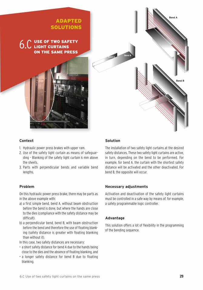
Context
1. Hydraulic power press brakes with upper ram. 2. Use of the safety light curtain as means of safeguar-
ding – Blanking of the safety light curtain 6 mm abovethe sheets.
3. Parts with perpendicular bends and variable bendlengths.
Problem
On this hydraulic power press brake, there may be parts asin the above example with:a) a first simple bend, bend A, without beam obstruction
before the bend is done, but where the hands are closeto the dies (compliance with the safety distance may bedifficult).
b) a perpendicular bend, bend B, with beam obstruction before the bend and therefore the use of floating blank-ing (safety distance is greater with floating blankingthan without it).
In this case, two safety distances are necessary:• a short safety distance for bend A due to the hands being
close to the dies and the absence of floating blanking, and • a longer safety distance for bend B due to floating
blanking.
Solution
The installation of two safety light curtains at the desiredsafety distances. These two safety light curtains are active,in turn, depending on the bend to be performed. For example, for bend A, the curtain with the shortest safetydistance will be activated and the other deactivated. Forbend B, the opposite will occur.
Necessary adjustments
Activation and deactivation of the safety light curtainsmust be controlled in a safe way by means of, for example,a safety programmable logic controller.
Advantage
This solution offers a lot of flexibility in the programmingof the bending sequence.
Bend ABend B
Bend A
Bend B
ADAPTED SOLUTIONS
6.C USE OF TWO SAFETY LIGHT CURTAINS ON THE SAME PRESS

In addition to the documents listed on page 2 under the heading Main documents for consultation, the followingdocuments served as references for the authors.
BOURBONNIERE, R., PAQUES, J-J., MONETTE, C., DAIGLE, R. Guide de conception des circuits de sécurité introductionaux catégories de la norme ISO 13849-1: 1999. R-405, IRSST, 2005, 73 p. (www.irsst.qc.ca/files/documents/PubIRSST/R-405.pdf)
International Electrotechnical Commission. Safety of machinery - Electro-sensitive protective equipment. Generalrequirements and tests. [Geneva] IEC/EN 61496-1, 2004.
International Electrotechnical Commission. Safety of machinery - Electro-sensitive protective equipment. Particularrequirements for equipment using active opto-electronic protective devices (AOPDs). [Geneva] IEC/EN 61496-2,2004.
International Electrotechnical Commission. Safety of machinery - Application of protective equipment to detect the presence of persons. [Geneva] IEC/EN 62046, 2008.
International Standard Organization. Safety of machinery – Safety-related parts of control systems - Part 1: General principles for design. [Geneva] ISO 13849-1: 2006, 2006.
International Standard Organization. Safety of machinery - Interlocking devices associated with guards - Principles for design and selection. [Geneva] ISO 14119: 1998, 1998.
International Standard Organization. Safety of machinery – Guards - General requirements for the design and construction of fixed and movable guards. [Geneva] ISO 14120: 2002, 2002.
LEMIEUX, G., CHINNIAH, Y., Safeguarding of power press brakes using light curtains and laser beams.In Proceedings of the 21st International Conference on Condition Monitoring and Diagnostic Engineering Management (COMADEM 2008), Czech Technical University, 11-12 June 2008: Prague, p. 293-307.
NGÔ, A.D., BEAUCHAMP, Y., LE-HUY, P. La sécurité dans l’utilisation de machines dangereuses. Les presses-plieuses dans le secteur de la fabrication d’équipement de transport et de machines. École de technologie supérieure, 1998, 50 p.
30 7. References
REFERENCES
7.
8. Appendices 31
APPENDICES
8.
The safety distance is the distance that ensures that hazardous movement is stopped before the operator canreach the zone where this movement occurs. Furthermore,Canadian standard CSA Z142-02 (clause 10.4 and AppendixE) defines the safety distance as follows: distance calcu-lated to be the minimum distance between the nearestpinch point and the safeguarding device in accordance withthis Standard. This minimum distance on a hydraulic powerpress brake must be calculated using the following formula:
Ds = [K * (Ts + Tc + Tr)] + Dpf
where:
Ds = minimum safety distanceK = 1.6 m/s hand-speed constant (metres per second)Ts = maximum machine stopping timeTc = maximum control system stopping timeTr = response time of the protective device (Tr = 0 for two-hand control device)
Dpf = maximum penetration through the sensitive devicebefore detection (see Appendix E of CSA Z142-02: Dpf = 0for two-hand control device; Dpf = 1.2 m for horizontallyconfigured safety light curtains; Dpf depends on the reso-lution for vertically configured curtains)
The value of the stopping time represented by the expres-sion (Ts + Tc + Tr) must also be verified by measurementson the machine.
European standard EN 12622: 2001 specifies that the safetydistance should not be less than 100 mm if the resolutionis equal to or less than 14 mm. In the specific case of a vertically installed safety light curtain, a hand speed of 2 m/s must be used. If the safety distance is greater than 500 mm, the calculation can be repeated with a hand speedof 1.6 m/s. However, with this hand speed, the safety distance cannot be less than 500 mm.
Although Canadian standard CSA Z142-02 recommends a minimum hand speed of 1.6 m/s, with the trunk immobile,some studies1 show that a higher speed should be considered.
8.A Safety distance for safety light curtains and two-hand control device on a hydraulicpower press brake
8.B Stopping distance for laser beams
This is the distance covered by the ram from the momentwhen the stop signal is given by a means of detection (e.g., crossing a laser beam) or by a person until it completely stops.
The stopping distance must be measured on the machine.
1 BÉLANGER, Raymond, Massé, Serge, Tellier, Chantal, Bourbonnière, Réal, Sirard, Christian, Évaluation des risques associés à l’utilisation des presses à métal dans l’industrie québécoise, R-085, IRSST, June 1994, p. 23.
32 8. Apendices
8.C Reliability of the safety-related control system
Safety-related control circuits on a press brake must be designed and built in such a way that a single failure orbreakdown in the system cannot prevent the normal stop-ping of the press when required, nor cause an unexpectedcycle, but prevents new press cycles by the usual meansuntil the failure is corrected.
Safety-related control circuits include:
- press cycle control circuits,- initiation control circuits,- electrical circuits that control the hydraulic valves,- electronic circuits that ensure self-monitoring of the
valves,- other components of the control system that have an
impact on the safeguarding of the working zone.
Information on the reliability of safety-related control systems:- CSA Z142-02, Code for Power Press Operation: Health, Safety,
and Guarding Requirements, clause 8. Control reliability.
- NF EN 12622: 2001, Safety of machine tools – Hydraulic pressbrakes.
- IRSST R-405, Guide de conception des circuits de sécurité introduction aux catégories de la norme ISO 13849-1: 1999.
8.D Reliability of the safety-related hydraulic system
Safety-related hydraulic circuits must have the same characteristics as those of safety related control circuits.
These circuits include:
- self-monitored directional valves, - self-monitored safety valves,- the other components of the hydraulic system.