Safe Working Procedures – Electronics - ME...
23
Transcript of Safe Working Procedures – Electronics - ME...

2
Safe Working Procedures – Electronics
Electronics activities should be confined to projects that only use extra - low-voltages. The activities include connecting electronic components in differing ways to create many useful and fun projects; these components have names such as resisters, diodes, transistors and capacitors. Identified Risks and Hazards Hazards that may be encountered in electronics activities could include: • Burns: from hot the soldering iron. You can also receive a burn from the
heat that remains in the electronic components and wire after it has been soldered.
• The hot soldering iron can melt the protective insulated leads and other equipment exposing live electrical wire that could cause electric shock.
• Flux is a mild acid solution and it corrosive form can burn skin. • Cuts from wire, sharp edges of materials, knives and cutting tools. • Breathing difficulties if excessive toxic fumes are inhaled during the soldering process Activity Location Considerations • The work area should be appropriate for electronics activities. Bench tops should be made of a suitable
material. Seat and bench heights need to be considered. • Adequate supervision of students in the work area should be maintained at all times. • First aid equipment and supplies should be available and easily accessible. Resource and Equipment Guidelines • All equipment should be in good condition and be regularly maintained. • Electrical equipment should be inspected regularly and where possible. It is advised that electrical
equipment have current electrical test certification. (AS/NZS 3760:2000) • Tools and materials should be stored appropriately to prevent personal injury from cutting edges, sharp
material edges and wire. • Ventilation such as having windows open and the use of fans is recommended when soldering because
the fumes given off may be harmful if inhaled in excessive amounts. • Fluxes assist the soldering process. Contact with the flux should be avoided as it is a mild corrosive
liquid and when heated the fumes from these fluxes can be toxic if inhaled. • A suitable soldering station - cradle should be used which allows the hot soldering iron to be stored and
stop it from coming into contact with anything, or any one. • Power boards with overload protection should be used. • Safety glasses reduce the risk of any splash of flux or other caustic liquid from entering the eyes. These
glasses can also reduce the risk of any other object from entering the eyes. General Electrical Safety • The general use of electricity inherently includes potential hazards that would normally require
precautions to be implemented including: - Never allow the use of an electrical appliance with a damaged plug or lead - The power switch must be switched off before removing the plug - Never attempt to touch a tool or lead where exposed conductors can be seen. Notify the teacher who will switch off the power to the room immediately. - Electrical tools must never be operated close to water or with someone with wet hands. Therefore all work areas are to be kept clean and dry at all times.

3
Soldering Tips and Techniques Learning to solder correctly from the start will save you many hours of frustrating troubleshooting, as poor solder joints are the main reason that projects do not work. Good soldering requires the right iron properly prepared, the right solder, a correctly prepared joint and practice, practice, practice. The Soldering Iron
An electric soldering iron of 10 - 30 watts rating with a 1.5 - 4mm chisel bit is ideal. Such an iron should give years of service if reasonable regular maintenance is performed. Once the iron has reached its operating temperature, simply wipe the tip on a piece of damp cloth. This should expose a shiny surface. Apply a small amount of solder to this tip. Your iron is now ready for service. Keep the tip clean at all times by periodically wiping it on a damp cloth or soldering sponge. The Solder The best solder for general electronics work is 60/40 solder. We recommend that you use a 60/40 solder that is pre-fluxed i.e. it has a small thread of flux running down the centre of the solder wire. Preparation They say that there are three rules to be observed when soldering. They are Cleanliness, Cleanliness and Cleanliness. Specifically, all parts of the joint to be soldered must be clean and free from tarnish, insulation and lacquers. If necessary, use sandpaper or a fine file to clean the parts to be soldered. Techniques One of the most common soldering problems occurring during electronics is "Poor" or "Cold" solder connections. Please observe the following guidelines for correct soldering techniques.
1. For the soldering iron to properly conduct heat, keep the tip
well tinned (coated with a thin layer of solder). To keep the tip clean, wipe it from time to time on a damp sponge or cloth.
2. Apply a flux to the areas to be soldered. 3. All component leads, wire leads and copper foil pads should be clean. 4. Place the tip of the soldering iron firmly against the area to be soldered. 5. Apply the solder to the connection as it is being heated. 6. Apply only enough solder to form a thin, smooth coating on all metal parts in the connection. 7. Continue to heat the connection for an INSTANT after you have stopped applying the solder. This will
aid the flow of solder and insure against "Poor" or "Cold" solder connections. 8. Do not move the solder connection until the solder has cooled (solidified). 9. It is advisable to secure the work to be soldered so it doesn’t move during soldering and affect the
accuracy of the joint to be soldered.
4
Electronic Circuits
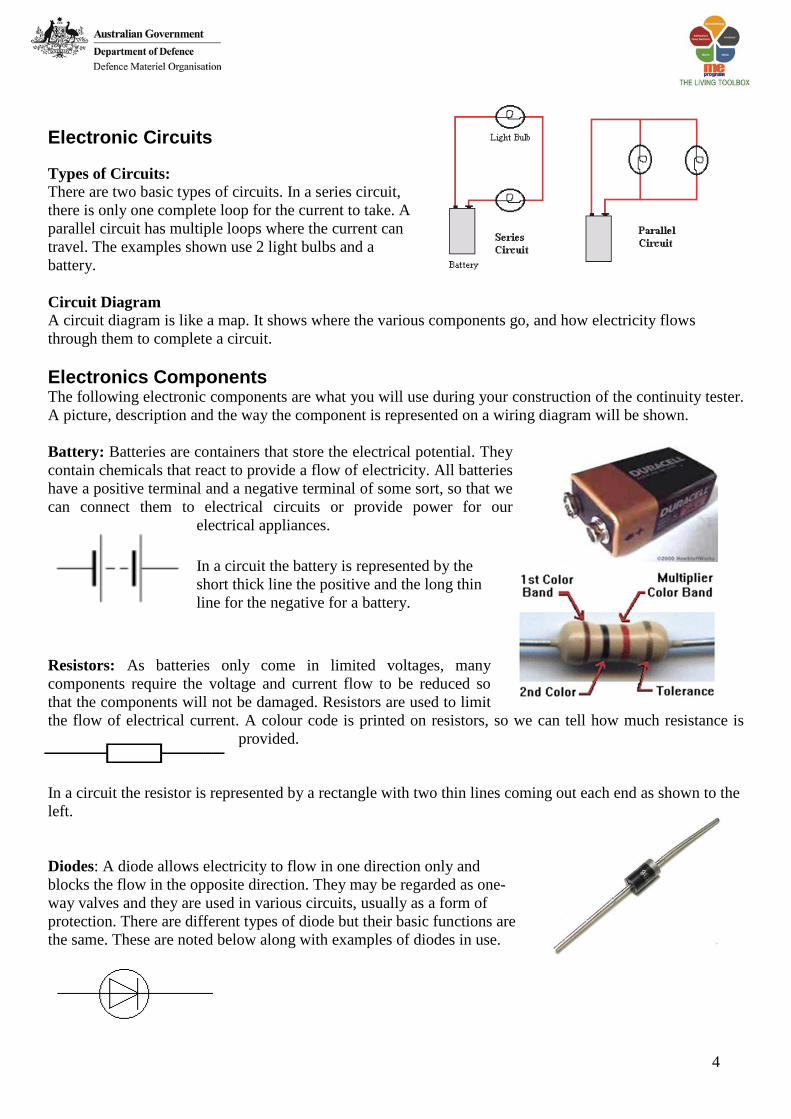
Types of Circuits: There are two basic types of circuits. In a series circuit, there is only one complete loop for the current to take. A parallel circuit has multiple loops where the current can travel. The examples shown use 2 light bulbs and a battery.
Circuit Diagram A circuit diagram is like a map. It shows where the various components go, and how electricity flows through them to complete a circuit. Electronics Components The following electronic components are what you will use during your construction of the continuity tester. A picture, description and the way the component is represented on a wiring diagram will be shown. Battery: Batteries are containers that store the electrical potential. They contain chemicals that react to provide a flow of electricity. All batteries have a positive terminal and a negative terminal of some sort, so that we can connect them to electrical circuits or provide power for our
electrical appliances. In a circuit the battery is represented by the short thick line the positive and the long thin line for the negative for a battery.
Resistors: As batteries only come in limited voltages, many components require the voltage and current flow to be reduced so that the components will not be damaged. Resistors are used to limit the flow of electrical current. A colour code is printed on resistors, so we can tell how much resistance is
provided.
In a circuit the resistor is represented by a rectangle with two thin lines coming out each end as shown to the left. Diodes: A diode allows electricity to flow in one direction only and blocks the flow in the opposite direction. They may be regarded as one-way valves and they are used in various circuits, usually as a form of protection. There are different types of diode but their basic functions are the same. These are noted below along with examples of diodes in use.

5
L.E.D: strands for “light emitting diode”. They are known as polarity specific that means that they need to be connected a certain way.
As you can see from the diagram the legs of the L.E.D. are different lengths, the longer leg connects to the positive side of the circuit. One can also tell which is the negative side from the front as the base rim of the L.E.D. has a flat edge next to the negative leg. When correctly connected in a circuit, they glow brightly. The advantage of L.E.D’s over normal light bulbs is how little power they use, how robust they are and how long they last.
Piezoelectric Buzzer: A piezo buzzer is nothing more than a piezo crystal trapped
between two metal plates. When an electric potential is applied to a piezo crystal, it will deform. The larger the potential, the larger the deformation and hence make a larger sound.
Battery Snap: A battery snap in electronics is what you connect a battery to. The battery snap then sends the electricity from the battery to the rest of the circuit.
Alligator Clips: Alligator clips are toothed clips on the ends of electric wires. They are hinged near the back, making them look like alligator jaws. Sometimes they are also called crocodile clips.
Jiffy Box: A Jiffy Box is an ABS plastic box which is used to house and protect electronics projects such as our continuity tester.

6
Focus on Literacy - Exposition Purpose To support ideas presented in sequence to justify a particular stand or viewpoint that a writer is taking. The writer's purpose is to take a position on some issue and justify it. An exposition consists of the following:
• a statement of position at the beginning • a logical sequence • the argument is put forward in a series of
points with back up evidence • a good argument shows cause and effect. This
is the connection between an action and what leads to it, eg. The fish died as a result of pollution in the water: Violence in movies contributes to violence in society
• a summing up or restating of position at the end Types of Expositions
• To plead a case - letters to the school principal / local council with regard to current issues. • To promote/sell goods and services - advertisement writing to promote the school concert/sports. • To put forward an argument - School uniforms should not be compulsory.
Language Features
• The exposition is written in the timeless present tense. This might change to the past if historical background to the issue was being given. If predictions are being made the tense might change to the future.
• The writer uses repetition of words, phrases and concepts deliberately, for effect. • Verbs are used when expressing opinions, eg. I think ___ are the best! We believe students should not be
stopped from eating junk food. • Strong effective adjectives are used. • Thought provoking questions are used. These may be asked as rhetorical questions. (Rhetorical questions: a
question asked only for effect, not for information, eg. Would you give your pre-schooler matches to play with?)
• Use of passive verbs to help structure the text. • Written in the timeless present tense. • Use of pronouns (I, we, us) is used to manipulate the reader to agree with the position argued. eg. We all
know that smoking causes cancer so we do not smoke. • Use of emotive language ie. words that will appeal to the reader's feelings, eg. concern, unreasonable, should. • Use of passive voice ie verbs in which the subject is acted upon and not doing the action. This helps structure
the text, eg. We would like to suggest that an enquiry be held into the running of the steel mills. Water is being polluted.
• Conjunctions that can exemplify and show results - they are usually used in concluding statements to finalise arguments

7
Focus on Literacy - Procedure Procedural Texts
Purpose The purpose is to tell the reader how to do or make something. The information is presented in a logical sequence of events, which is broken up into small sequenced steps. These texts are usually written in the present tense. The most common example of a procedural text is a recipe. Types of Procedural Texts There are different procedural texts for different purposes:-
• Texts that explain how something works or how to use instruction /operation manuals eg how to use the video, the computer, the tape recorder, the photocopier, the fax.
• Texts that instruct how to do a particular activity eg recipes, rules for games, science experiments, road safety rules.
• Texts that deal with human behaviour eg how to live happily, how to succeed. Features Structure
• Goal - clearly stated (often in the heading) • Materials - listed in order of use • Method - the steps are chronological and are numbered or listed
Each type of procedural text has a format
• Recipes usually have the information presented in at least two basic groups: ingredients and method. • Games instructions usually include instructions on how to play, rules of the game, method of scoring,
and the number of players. • Scientific experiments usually include the purpose of the experiment, equipment, procedure,
observations and conclusion.
Language The text usually:
• focuses on generalised people rather than individuals (first you take, rather than first I take) • the reader is often referred to in a general way, ie. pronouns (you or one) • action verbs (imperative verbs), (cut, fold, twist, hold etc) • simple present tense (you cut, you fold, you mix) • linking words to do with time (first, when, then) are used to connect the text • detailed information on how (carefully, with the scissors); where (from the top); when (after it has
set) • detailed factual description (shape, size, colour, amount)

8
Automation
Automation is the use of control systems and information technologies to reduce the need for human work in the production of goods and services. In the scope of industrialisation, automation is a step beyond mechanisation. Whereas mechanisation provided human operators with machinery to assist them with the muscular requirements of work, automation greatly decreases the need for human sensory and mental requirements as well. Automation plays an increasingly important role in the world economy and in daily experience.
Automation has had a notable impact in a wide range of industries beyond manufacturing (where it began). Once-ubiquitous telephone operators have been replaced largely by automated telephone switchboards and answering machines. Medical processes such as primary screening in electrocardiography or radiography and laboratory analysis of human genes, sera, cells, and tissues are carried out at much greater speed and accuracy by automated systems. Automated teller machines have reduced the need for bank visits to obtain cash and carry out transactions. In general, automation has been responsible for the shift in the world
economy from industrial jobs to service jobs in the 20th and 21st centuries. Advantages and disadvantages The main advantages of automation are:
• Replacing human operators in tasks that involve hard physical or monotonous work. • Replacing humans in tasks done in dangerous environments (i.e. fire, space, volcanoes, nuclear
facilities, underwater, etc.) • Performing tasks that are beyond human capabilities of size, weight, speed, endurance, etc. • Economy improvement: Automation may improve in economy of enterprises, society or most of
humanity. For example, when an enterprise invests in automation, technology recovers its investment; or when a state or country increases its income due to automation like Germany or Japan in the 20th Century.
• Reduces operation time and work handling time significantly. The main disadvantages of automation are:
• Unemployment rate increases due to machines replacing humans and putting those humans out of their jobs.
• Technical Limitation: Current technology is unable to automate all the desired tasks. • Security Threats/Vulnerability: An automated system may have limited level of intelligence,
hence it is most likely susceptible to commit error. • Unpredictable development costs: The research and development cost of automating a process
may exceed the cost saved by the automation itself. • High initial cost: The automation of a new product or plant requires a huge initial investment in
comparison with the unit cost of the product, although the cost of automation is spread in many product batches of things

9
Robotics Case Study – Parrot Drone Quadcopter So you have seen the Parrot AR Drone Helicopter fly and you are wondering how it works? The combination of rotors, computers, cameras, and sensors has made this device a hit amongst people holding a variety of interests, be it an interest in aviation, technology, or just the coolest new gadgets available on the market. The AR.Drone works by through a variety of technology combinations. The body is made from a carbon fiber, as well as a mixture of highly durable plastics. The quadricopter rotary has four high powered rotors to lift the device into flight. The device itself has a built in computer MEMS (Micro-Electro-Mechanical Systems), as well as a Wi-Fi processor for interfacing with the control device - an iPhone or an iPad.
Two cameras are included in the device, each with its own purpose. The bottom camera helps the AR.Drone function by determining speed, location, and other important information for the on board computer. This camera is used to give the unit its excellent stationary flying, it also looks after things like wind turbulences to give it a more stable flying experience. While the front camera which is mounted on the front of the Parrot AR Drone Helicopter
broadcasts via Wi-Fi to your iPhone or iPad. The AR Drone’s height is determined by two ultrasonic altimeters mounted at the bottom of the Drone. The Parrot AR. Drone works through the use of gyroscopes, accelerometers, and a Microelectromechanical system. These devices, backed by the built in computer, force the device into operation with the simple use of your Apple device. The iPhone or iPod will control steering, take off, landing, and other functions to be performed by the AR. Drone - including Reality Video Games. Autopilot The AR. Drone autopilot allows easy take-off and landing. After take-off, autopilot stabilizes the quadricopter at 50 centimetres high. When the pilot removes his fingers from the iPad screen, the autopilot puts the AR. Drone in hover mode. The autopilot will also take command when the Wi-Fi connection is lost. It stabilises the AR. Drone before a soft landing. The AR. Drone is controlled by the iPads accelerometer, if you tilt your iPad forwards the quadricopter moves forwards, if you tilt it sideways it will turn in the direction you moved your iPhone.
See the AR. Drone in action http://www.youtube.com/watch?v=CG5pqTWVahQ

10
The Technologies of AR. Drone Quadcopter Gyroscopes "A gyroscope is a device for measuring or maintaining orientation, based on the principles of conservation of angular momentum." Gyroscopes can be very perplexing objects because they move in peculiar ways and even seem to defy gravity. These special properties make - gyroscopes extremely important in everything from your bicycle to the advanced navigation system on the space shuttle. A typical airplane uses about a dozen gyroscopes in everything from its compass to its autopilot. The Russian Mir space station used 11 gyroscopes to keep its orientation to the sun, and the Hubble Space Telescope has a batch of navigational gyros as well. Gyroscopic effects are also central to things like yo-yos and Frisbees! Precession This is the gravity-defying part of a gyroscope. The following video shows you the effects of precession using a bicycle wheel as a gyro:
http://www.youtube.com/watch?v=IEwAry0GARw
The most amazing section of the video, and also the thing that is unbelievable about gyroscopes, is the part where the gyroscopic bicycle wheel is able to hang in the air like this: How can it do that? This mysterious effect is precession. In the general case,
precession works like this: If you have a spinning gyroscope and you try to rotate its spin axis, the gyroscope will instead try to rotate about an axis at right angles to your force axis, like this: Uses of Gyroscopes The effect of all this is that, once you spin a gyroscope, its axle wants to keep pointing in the same direction. If you mount the gyroscope in a set of gimbals so that it can continue pointing in the same direction, it will. This is the basis of the gyro-compass. If you mount two gyroscopes with their axles at right angles to one another on a platform, and place the platform inside a set of gimbals, the platform will remain completely rigid as the gimbals rotate in any way they please. This is this basis of inertial navigation systems (INS).
In an INS, sensors on the gimbals' axles detect when the platform rotates. The INS uses those signals to understand the vehicle's rotations relative to the platform. If you add to the platform a set of three sensitive accelerometers, you can tell exactly where the vehicle is heading and how its motion is changing in all three directions. With this information, an airplane's autopilot can keep the plane on course, and a rocket's guidance system can insert the rocket into a desired orbit!
The iPhone and iPad used to move the AR. Drone also uses Gyroscopes to help determine when the user moves the tablet or phone device. The iPhone and iPad utilise a microscopic, electronic version of a vibrational gyroscope, called a MEMS gyroscope.
11
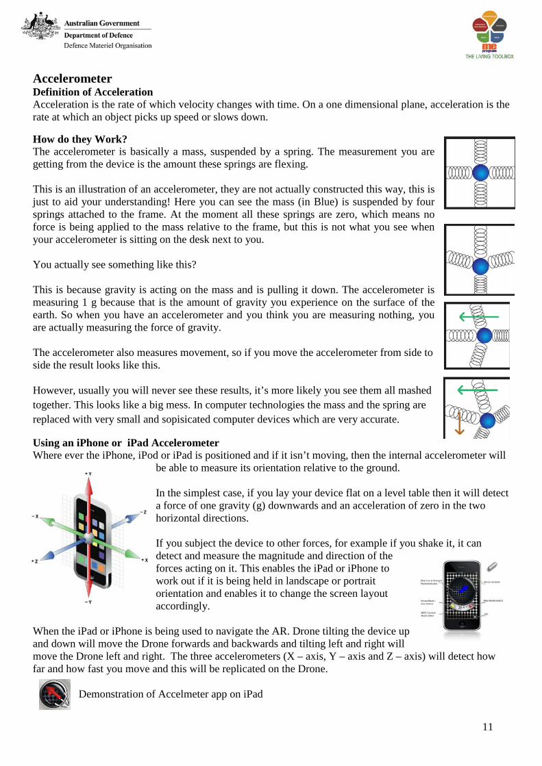
Accelerometer Definition of Acceleration Acceleration is the rate of which velocity changes with time. On a one dimensional plane, acceleration is the rate at which an object picks up speed or slows down. How do they Work? The accelerometer is basically a mass, suspended by a spring. The measurement you are getting from the device is the amount these springs are flexing. This is an illustration of an accelerometer, they are not actually constructed this way, this is just to aid your understanding! Here you can see the mass (in Blue) is suspended by four springs attached to the frame. At the moment all these springs are zero, which means no force is being applied to the mass relative to the frame, but this is not what you see when your accelerometer is sitting on the desk next to you. You actually see something like this? This is because gravity is acting on the mass and is pulling it down. The accelerometer is measuring 1 g because that is the amount of gravity you experience on the surface of the earth. So when you have an accelerometer and you think you are measuring nothing, you are actually measuring the force of gravity. The accelerometer also measures movement, so if you move the accelerometer from side to side the result looks like this. However, usually you will never see these results, it’s more likely you see them all mashed together. This looks like a big mess. In computer technologies the mass and the spring are replaced with very small and sopisicated computer devices which are very accurate.
Using an iPhone or iPad Accelerometer Where ever the iPhone, iPod or iPad is positioned and if it isn’t moving, then the internal accelerometer will
be able to measure its orientation relative to the ground. In the simplest case, if you lay your device flat on a level table then it will detect a force of one gravity (g) downwards and an acceleration of zero in the two horizontal directions. If you subject the device to other forces, for example if you shake it, it can detect and measure the magnitude and direction of the forces acting on it. This enables the iPad or iPhone to work out if it is being held in landscape or portrait orientation and enables it to change the screen layout accordingly.
When the iPad or iPhone is being used to navigate the AR. Drone tilting the device up and down will move the Drone forwards and backwards and tilting left and right will move the Drone left and right. The three accelerometers (X – axis, Y – axis and Z – axis) will detect how far and how fast you move and this will be replicated on the Drone.
Demonstration of Accelmeter app on iPad

12
MicroElectroMechanical systems (MEMS) MEMS are tiny mechanical devices that are built onto semiconductor chips and are measured in micrometers. In the research labs since the 1980s, MEMS devices began to materialise as commercial products in the mid-1990s. They are used to make pressure, temperature, chemical and vibration sensors, light reflectors and switches as well as accelerometers for airbags, vehicle control, pacemakers and games. The technology is also used to make inkjet print heads, microactuators for read/write heads and all-optical switches that reflect light beams to the appropriate output port.
The figure to the left is a dual-axis thermal accelerator which is MEMS-based semiconductor device that works conceptually like the air bubble in a construction level. The square in the middle of the chip is a resistor that heats up a gas bubble. The next larger squares contain thermal couples that sense the location of the heated bubble as the device is tilted or accelerated. (Image courtesy of MEMSIC, Inc.) This is the device in an iPad or iPhone which allows the screen to move as you tilt it from side to side.
Ultrasonic Sensors Watch you tube video for basic description of what Ultrasonic sensors are used for.
http://www.youtube.com/watch?v=ueqRp_XYau8 The theory behind the ultrasound sensor is based on echo-location (like SONAR, the same thing bats use to navigate). The pitch, or frequency, of the sound is so high that humans cannot detect it, which is useful because it provides accuracy and remains inconspicuous. As sound hits a solid object, it is reflected back creating an echo. Since the speed of sound is known and constant for similar conditions, (such as wind or humidity to name a few), it is possible to determine the distance of the object you hear an echo from by multiplying the speed of sound by half the time it takes to hear the echo (because the echo time is actually the time it takes the sound to go there and back).
The Ping sensor in the AR. Drone is an ultrasonic sensor which allows it to measure automatically and continuously distance between moving or stationary objects, a very handy capability when it comes to create an autonomous aircraft like the Quadcopter.
13
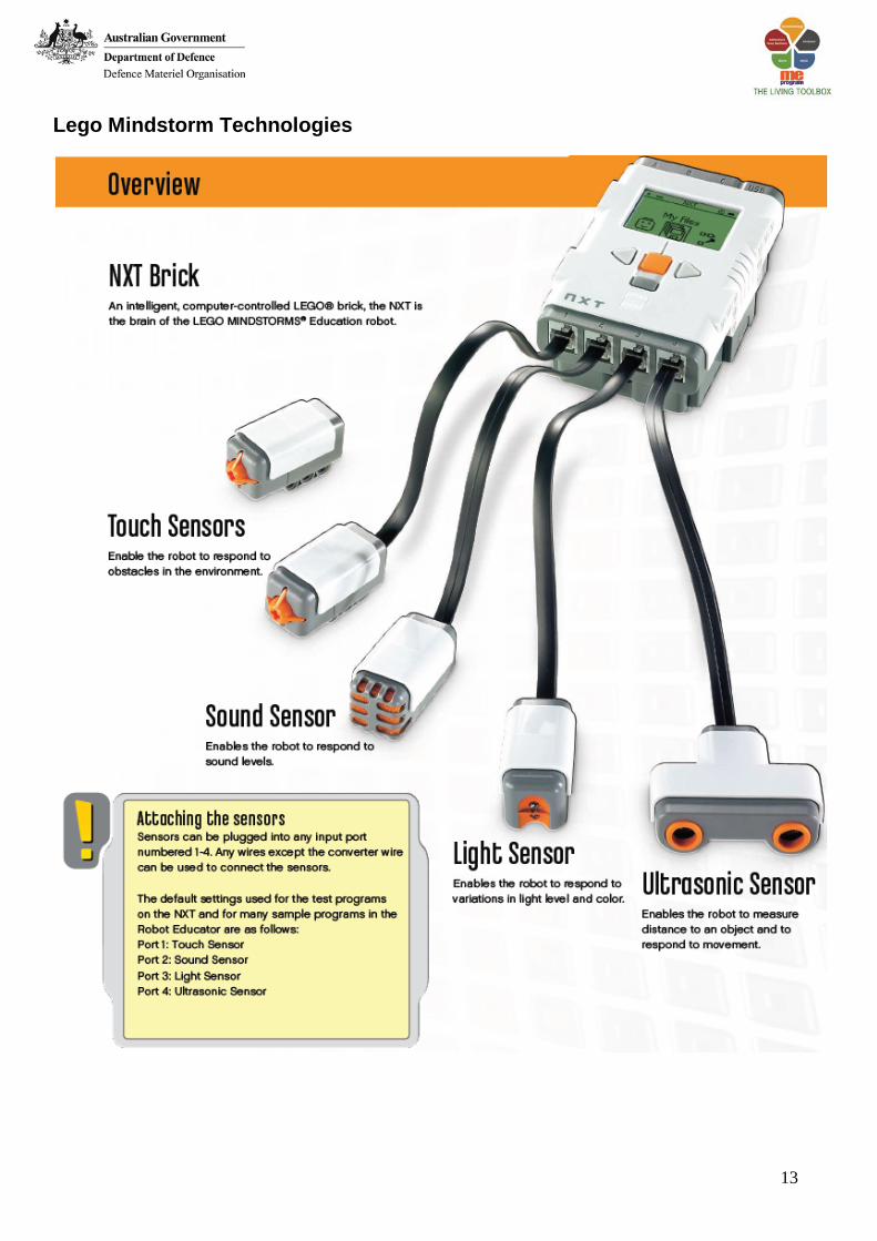
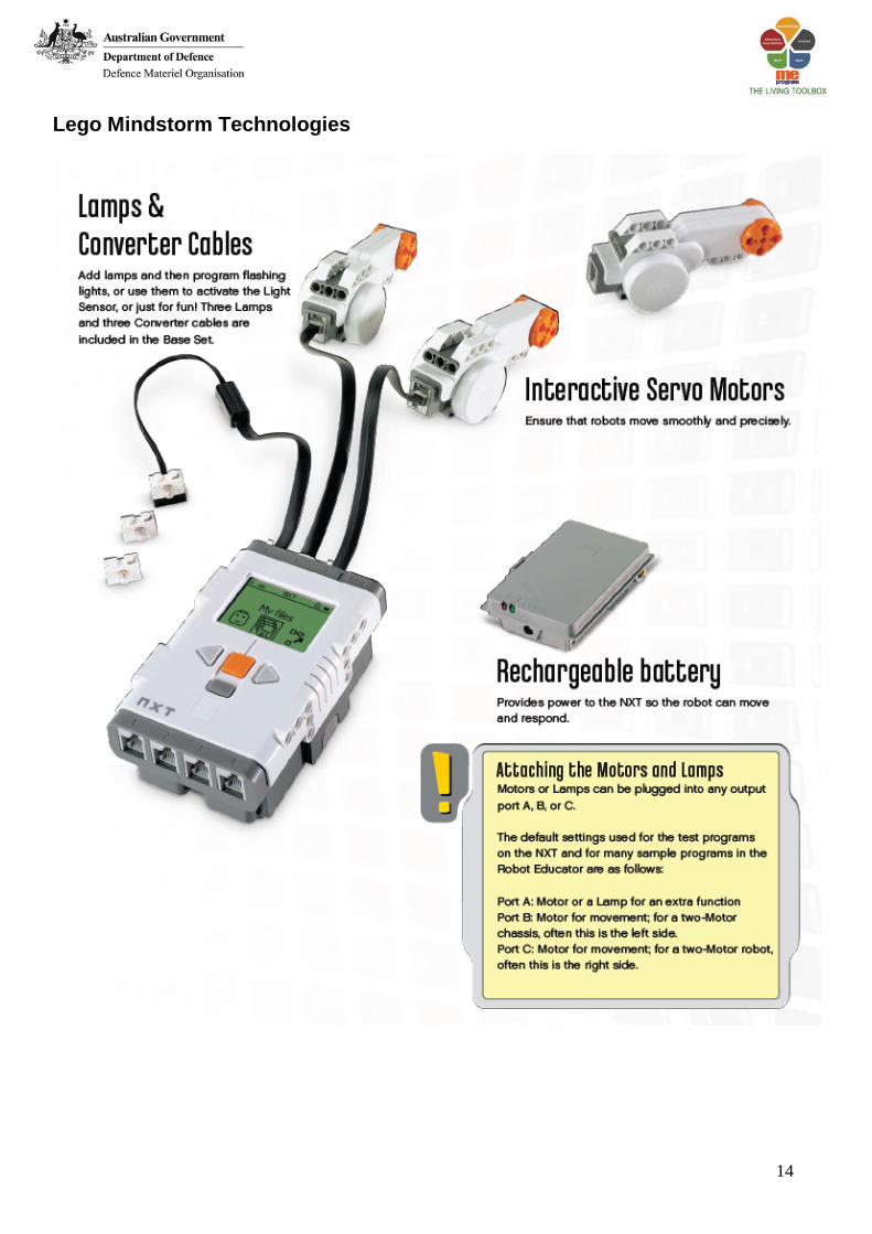
Lego Mindstorm Technologies
14
Lego Mindstorm Technologies
15
Sensors – 1. Touch
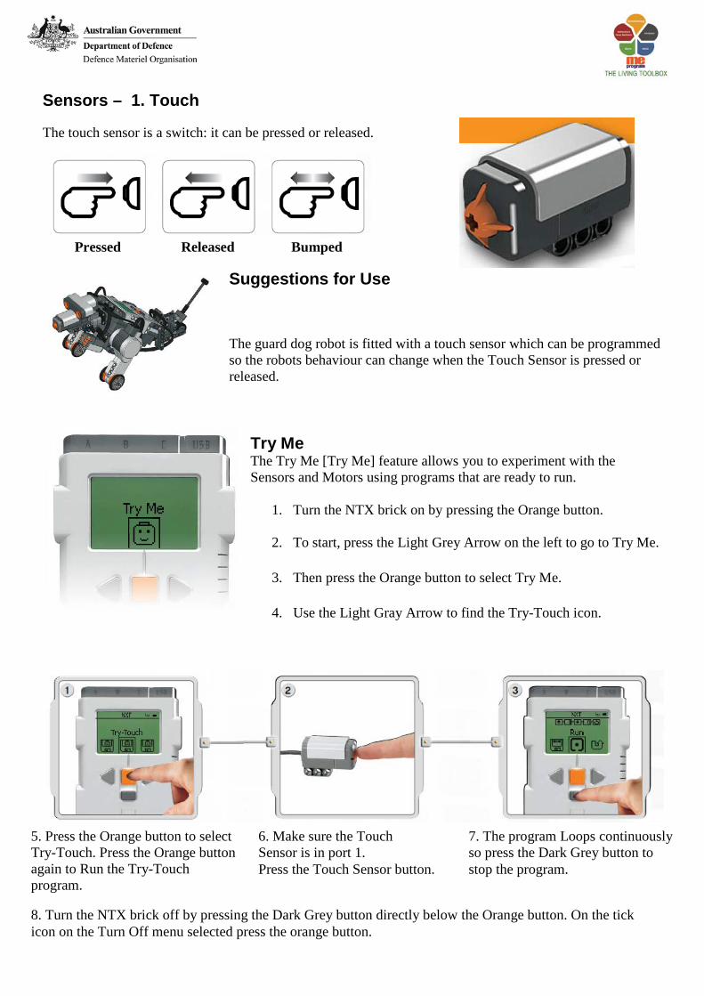
The touch sensor is a switch: it can be pressed or released.
Pressed Released Bumped
Suggestions for Use
The guard dog robot is fitted with a touch sensor which can be programmed so the robots behaviour can change when the Touch Sensor is pressed or released.
Try Me The Try Me [Try Me] feature allows you to experiment with the Sensors and Motors using programs that are ready to run.
1. Turn the NTX brick on by pressing the Orange button.
2. To start, press the Light Grey Arrow on the left to go to Try Me.
3. Then press the Orange button to select Try Me.
4. Use the Light Gray Arrow to find the Try-Touch icon.
5. Press the Orange button to select Try-Touch. Press the Orange button again to Run the Try-Touch program.
6. Make sure the Touch Sensor is in port 1. Press the Touch Sensor button.
7. The program Loops continuously so press the Dark Grey button to stop the program.
8. Turn the NTX brick off by pressing the Dark Grey button directly below the Orange button. On the tick icon on the Turn Off menu selected press the orange button.

16
Software User Interface
1. Robot Educator Here you can find building and programming instructions using the Robot Educator model. 2. My Portal Here you can access www.MINDSTORMSeducation.com for tools, downloads, and information. 3. The tool bar The tool bar includes the most frequently used commands from the menu bar in an easy-to-reach location. 4. The work area This is the space on the screen where programming takes place. Drag programming blocks from the programming palette to the work area and attach the blocks to the sequence beam. 5. Little Help window Here you can always get help if needed. 6. The work area map Use the pan tool on the tool bar to move around the work area – and use the work area map [tab in the lower right corner to get an overview. 7. The programming palette The programming palette contains all of the programming blocks you will need to create your programs. The tabs at the bottom of the palette let you switch between the common palette [containing the most frequently used blocks], the complete palette [containing all of the blocks], and the custom palette [containing blocks that you can download or create on your own]. 8. The configuration panel Each programming block has a configuration panel that lets you customize the block for the specific input and output that you want. 9. The Controller The five buttons on the Controller let you download programs (or parts of programs) from your computer to the NXT. With the Controller you can also change the settings of the NXT. 10. The NXT window This pop-up window provides information about the NXT memory and communication settings.
1
2 3
4
5 6
7
8
9
10

17
Your First Program This simple program will make the Guard Dog move forward until it hits a wall go backwards and play a sound file. It will help you understand how to connect your computer to the NXT. 1. Start the software on your PC or Laptop by double-clicking the program icon.
2. Type in the name of your first program, and click Go!
3. First, click on the Move [Move] block icon in the programming palette.
4. Drag a Move [Move] block and drop it to the right of the Starting point in the work area. 5. In the Configuration Panel, near duration, change from Rotations to Unlimited.
6. Click on the Wait icon in the Programming Palette, and five new options will become available, click on
Touch.
7. Drag the Touch block and drop it to the right of the Move block.
8. Click on another Move block and drag it to the right of the Touch block.
1
2
3
4
5
6
7
8

18
9. In the Configuration Panel click the Stop radio button shown below.
10. Click on the Sound icon in Programming Palette, and click on the Speaker block. Drag and drop the icon
next the second Move block. 11. Select an appropriate sound from the file section in the Configuration panel shown below. 12. Add another Move block by dropping it to the right of the speaker icon. 13. In the Configuration Panel click on the Backwards arrow radio box to make the robot go backwards 14. In the Configuration Panel change the Duration from Rotations to Seconds and the number to 5. 15. Turn on your NXT and connect the USB cable to both your computer and the NXT 16. Locate the Controller in the lower right corner of the work area. Click Download and run (the center
button) and listen to what happens. Congratulations, you have completed your first program! 17. Disconnect the USB cable from the Guard Dog and press the Orange button on My Files. Click the Orange button on Software files icon and click again to select My First program. 18. Move the Guard Dog to an appropriate location and click the Orange button to run
the program.
9
10
11
12
13
14 15
16

19
Sensors – 2. Sound
The Sound Sensor detects the decibel level: the softness or loudness of a sound. The Sound Sensor detects both dB and dBA. dBA: the sounds human ears are able to hear. dB: all actual sound, including sounds too high or low for the human ear to hear. The Sound Sensor can measure sound pressure levels up to 90 dB – about the level of a lawnmower. Sound sensor readings on the LEGO® MINDSTORMS® NXT are displayed in the percentage [%] of sound the sensor is capable of reading.
For comparison, 4-5% is like a silent living room and 5-10% is about the level of someone talking some distance away. From 10-30% is normal conversation close to the sensor or music played at a normal level and 30-100% represents a range from people shouting to music playing at high volumes. These ranges are assuming a distance of about 1 meter between the sound source and the Sound Sensor.
Suggestions for use You can add the Sound Sensor to an NXT model and then program the model behaviour to change when the Sound is activated. View Test the Sound Sensor’s ability to measure sound volume using View [View]. Connect the Sound Sensor to NXT port 2.
Task Modify your first program to include a sound sensor. Make the Guard Dog move when you chap your hands.
Select View [View] in the NXT display. Click on the light grey arrow keys to find view menu. Select the Sound dB icon. Select port 2.
Make sounds into the microphone (Sound Sensor) and see the readings on the NXT. Try also to read the sounds around you: How loud are the nearest voices?
20
Sensors – 3. Ultrasonic
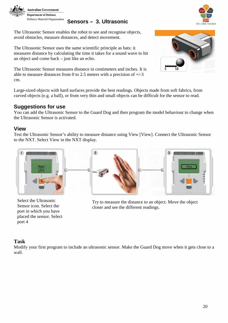
The Ultrasonic Sensor enables the robot to see and recognise objects, avoid obstacles, measure distances, and detect movement. The Ultrasonic Sensor uses the same scientific principle as bats: it measures distance by calculating the time it takes for a sound wave to hit an object and come back – just like an echo. The Ultrasonic Sensor measures distance in centimeters and inches. It is able to measure distances from 0 to 2.5 meters with a precision of +/-3 cm. Large-sized objects with hard surfaces provide the best readings. Objects made from soft fabrics, from curved objects (e.g. a ball), or from very thin and small objects can be difficult for the sensor to read. Suggestions for use You can add the Ultrasonic Sensor to the Guard Dog and then program the model behaviour to change when the Ultrasonic Sensor is activated. View Test the Ultrasonic Sensor’s ability to measure distance using View [View]. Connect the Ultrasonic Sensor to the NXT. Select View in the NXT display.
Task Modify your first program to include an ultrasonic sensor. Make the Guard Dog move when it gets close to a wall.
Select the Ultrasonic Sensor icon. Select the port in which you have placed the sensor. Select port 4
Try to measure the distance to an object. Move the object closer and see the different readings.

21
Sensors – 4. Light The Light Sensor enables the robot to distinguish between light and darkness, to read the light intensity in a room, and to measure the light intensity on coloured surfaces.
Suggestions for use You can add the Light Sensor to the Guard Dog and then program the model behaviour to change when the Light Sensor is activated. View You can test the Light Sensor in different ways using View [View]. Viewing reflected light turns on the flood light in the sensor. Viewing Reflected Light to see Colours. Connect the Light Sensor to the NXT. Select View in the NXT display.
Viewing Ambient light
This is what your eyes see. This is what your robot sees using the light sensor.
Select the Reflected light icon. Select port 3
Hold the Light Sensor close to the different colours in your surrounding and see the different readings. You can use the colour chart on page 69 of the user guide.
Test the Light Sensor’s ability to read the surrounding light by measuring the light level in different parts of the room. For example, first hold the sensor against the window, then hold it under the table. Notice the difference in the readings. Higher numbers indicate more light (as a percentage of the light the sensor can read). Lower numbers indicate a lower amount of light.
Select the ambient light icon. Select port 3.
22
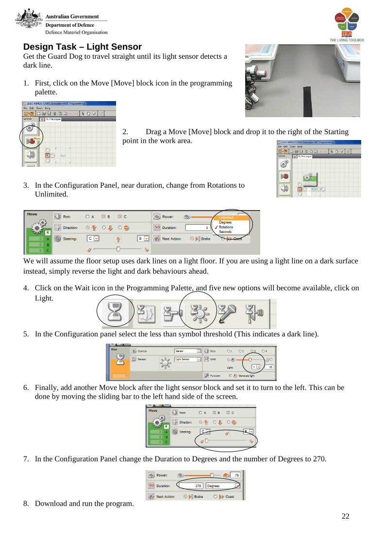
Design Task – Light Sensor Get the Guard Dog to travel straight until its light sensor detects a dark line. 1. First, click on the Move [Move] block icon in the programming
palette. 2. Drag a Move [Move] block and drop it to the right of the Starting point in the work area.
3. In the Configuration Panel, near duration, change from Rotations to
Unlimited.
We will assume the floor setup uses dark lines on a light floor. If you are using a light line on a dark surface instead, simply reverse the light and dark behaviours ahead.
4. Click on the Wait icon in the Programming Palette, and five new options will become available, click on Light.
5. In the Configuration panel select the less than symbol threshold (This indicates a dark line). 6. Finally, add another Move block after the light sensor block and set it to turn to the left. This can be
done by moving the sliding bar to the left hand side of the screen.
7. In the Configuration Panel change the Duration to Degrees and the number of Degrees to 270. 8. Download and run the program.

23
Aboriginal Perspective Aboriginal peoples have been producing visual art for many thousands of years. It takes many forms - ancient engravings and rock art, designs in sand or on the body, exquisite fibre craft and wooden sculptures, bark paintings and more recently an explosion of brilliant contemporary painting. Rock Art Most artworks in the distant past were made with materials that have not survived the passing of time. Rock art however has left rich and enduring evidence of human presence in Australia for at least 30 000 years. Aboriginal Australians believe they have been here since the Dreamtime. Art and Aboriginal Society Traditional Aboriginal societies vary greatly across Australia but all have social structures and systems that organise life and experience and explain the universe and the place of people in it. Art is part of these systems and the making of artworks by Aboriginal artists is almost always connected to Dreaming stories. The ownership of Dreaming stories is determined by complex social and kinship structures and paintings can only be produced by those who are acknowledged to have the right to do so. But this does not mean that artists are rigidly bound by convention in their expressions of these stories - as the great flowering of innovation in contemporary Aboriginal art shows. Contemporary Aboriginal Art Since the early 1970s, Aboriginal contemporary art has grown rapidly and with amazing diversity and vigour - to the extent that critic Robert Hughes has described it as the 'last great art movement of the 20th Century'. The beginning of this growth can be traced to a school building in Papunya, a remote community in the Western Desert. The cultural pride expressed at Papunya has since spread widely in Aboriginal communities across Australia. Aboriginal Bird Paintings Below are a number of bird paintings which have been produced by indigenous Australians. Use these paintings as possible inspiration for your graphical art designs.
Rockart at the Split Rock Gallery near Laura, Queensland