
Safe Handling of Tank Containers
80
INTERNATIONAL SAFETY PANEL SAFETY BRIEFING PAMPHLET SERIES # 30 Safe Handling of Tank Containers By Bill Brassington ICHCA INTERNATIONAL PREMIUM MEMBERS:
-
Upload
kimberly-conley -
Category
Documents
-
view
67 -
download
0
description
Handling of Containers
Transcript of Safe Handling of Tank Containers

INTERNATIONAL SAFETY PANEL
SAFETY BRIEFING PAMPHLET SERIES # 30
Safe Handling of Tank Containers
By
Bill Brassington
ICHCA INTERNATIONAL PREMIUM MEMBERS:

ICHCA International Safety Panel Safety Briefing Pamphlet #30
© ICHCA International Limited
ICHCA INTERNATIONAL LIMITED is an independent, non-political international membershiporganisation and is dedicated to the promotion of safety and efficiency in the handling andmovement of goods by all modes and during all phases of both the national and internationaltransport chains. Originally established in 1952 and incorporated in 2002, it operates througha series of Local, National and Regional Chapters, Panels, Working Groups andCorrespondence Groups and represents the cargo handling world at various internationalorganisations, including the International Maritime Organization (IMO), United NationsConference on Trade and Development (UNCTAD), International Labour Organization (ILO)and the International Standards Organization (ISO).
Its members included ports, terminals, transport companies and other groups associated withcargo handling and coordination. Members of ICHCA International Panels represent asubstantial cross-section of senior experts and professionals from all sectors of the cargotransport industry globally. Members benefit from consulting services and informativepublications dealing with technical matters, “best practice” advice and cargo handling news.
For more information on ICHCA International and its services please visit/contact –
ICHCA International Limited Tel: +44 (0) 1708 735295Suite 2, 85 Western Road, Fax: +44 (0) 1708 735225Romford, Essex, RM1 3LS Email: [email protected] Kingdom Website: www.ichca.com
ICHCA International Safety Panel Briefing Pamphlet No 30
©ICHCA International Limited
The International Safety Panel Briefing Pamphlet series consists of the followingpamphlets:
No. 1 International Labour Office (ILO) Convention No. 152 OccupationalSafety and Health in Dockwork (revised)
No. 2 Ships Lifting Plant (revised)No. 3 The International Maritime Dangerous Goods (IMDG) Code (revised))No. 4 Classification Societies (revised)No. 5 Container Terminal Safety (under revision)No. 6 Guidance on the Preparation of Emergency Plans (under revision)No. 7 Safe Cleaning of Freight Containers (under revision)No. 8 Safe Working on Container ShipsNo. 9 Safe Use of Flexible Intermediate Bulk Containers (FIBCs) (revised)No. 10 Safe Working at Ro-Ro TerminalsNo. 11 The International Convention for Safe Containers (CSC) (under revision)No. 12 Safety Audit System for PortsNo. 13 The Loading and Unloading of Solid Bulk Cargoes (under revision)No. 14 The Role of the Independent Marine Surveyor in Assisting Claims
HandlingNo. 15 Substance AbuseNo. 16 Safe Use of Textile SlingsNo. 17 Shore Ramps and Walkways (under revision)No. 18 Port State ControlNo. 19 Safe Handling of Interlocked FlatsNo. 20 Unseen Dangers in ContainersNo. 21 Stow it rightNo. 22 Suspension TraumaNo. 23 Safe Handling of Forest ProductsNo. 24 Safe use of Road Vehicle TwistlocksNo. 25 An illustrated Guide to Container Size and Type CodesNo. 26 Safe Handling of Bulk Liquids & GasesNo. 27 Safe Working with PalletsNo. 28 Safe SlingingNo. 29 Safe Handling of Logs from Water in British Columbia
The International Safety Panel Research Paper series consists of the followingresearch papers:
No. 1 Semi-Automatic Twistlocks (under revision)No. 2 Fumes in Ships Holds (revised)No. 3 Health & Safety Assessments in Ports (under revision)No. 4 Container Top Safety, Lashing and Other Related MattersNo. 5 Port & Terminal Accident Statistics (under revision)No. 6 Safe Handling of Radioactive Materials in Ports and Harbour Areas
(under revision)No. 7 Ship Design Considerations for Stevedore Safety (under revisionNo. 8 Safe Walkways in Port & Terminal AreasNo. 9 Personal Protective Equipment & ClothingNo. 10 Back PainNo. 11 Lifting Persons at Work for Cargo Handling Purposes in the Port
IndustryNo. 12 Whole Body VibrationNo. 13 Lifting Containers by Rubber Tyred Gantry CranesNo. 14 Lashing of Deck ContainersNo. 15 Terminal Operations in High Winds

ICHCA International Safety Panel Briefing Pamphlet No 30
©ICHCA International Limited
The International Safety Panel Technical/Operational Advice series consists of thefollowing:
No. 1 Vertical Tandem Lifting of Freight ContainersNo. 1A Vertical Tandem Lifting – Operations ChecklistNo. 2 Horizontal lashing of Container Vessels – Safety Aspects of Lashing
on Deck 40’ and 45’ Containers with particular regard to horizontallashings
Plasticised Pocket Cards
IIL/1 Dangerous Goods by Sea DocumentationIIL/2 Dangerous Goods by Sea: The IMDG Code Labels, Placards, Marks
and SignsIIL/3 Confined Spaces on Board Dry Cargo Ships
General Advice Series
No. 1 Guidelines to Shipping Packaged Dangerous Goods by Sea – adviceto consignors and shippers
No. 2 Fire Fighting in Ports and on Ships
Other titles in many of the series are in preparation
This publication is one of a series developed by the International Safety Panel("Safety Panel") of ICHCA International Limited ("ICHCA"). The series is designed toinform those involved in the cargo-handling field of various practical health and safetyissues. ICHCA aims to encourage port safety, the reduction of accidents in port workand the protection of port workers' health.
ICHCA prepares its publications according to the information available at the time ofpublication. This publication does not constitute professional advice nor is it anexhaustive summary of the information available on the subject matter to which thepublication refers. The publication should always be read in conjunction with therelevant national and international legislation and any applicable regulations,standards and codes of practice. Every effort is made to ensure the accuracy of theinformation but neither ICHCA nor any member of the Safety Panel is responsible forany loss, damage, costs or expenses incurred (whether or not in negligence) arisingfrom reliance on or interpretation of the publication.
The comments set out in this publication are not necessarily the views of ICHCA orany member of the Safety Panel
All rights reserved. No part of this publication may be reproduced or copied withoutICHCA's prior written permission. For information, contact ICHCA's registered office.

ICHCA International Safety Panel Briefing Pamphlet No 30
©ICHCA International Limited
ICHCA International Limited - INTERNATIONAL SAFETY PANELThe International Safety Panel is composed of safety and training officers anddirectors, transport consultants, representatives from leading safety and trainingorganisations, enforcement agencies, trade unions, insurance interests, institutionsand leading authorities on the subject area from around the world.
Mike Compton (Chairman), Circlechief AP, UKJohn Alexander, UKMeir Amar, Ashod Port Company Limited, ISRAELPaul Auston, Checkmate UK Limited, UKDavid Avery, Firefly Limited, UKPeter Bamford, CANADAJan Boermans, P&O Ports, THE NETHERLANDSMike Bohlman, Horizon Lines, USA (Deputy Chairman)Roy Boneham, UKBill Brassington, ETS Consulting, UKJim Chubb, BMT Murray Fenton Limited, UKGary Danback, IICL, USARob Dieda, SSA, USATrevor Dixon, World Nuclear Transport Institute, UKSteve Durham, Trinity House, UKPatricia Esquival, OPCSA, SPAINMargaret Fitzgerald, IRELANDPamela Fry, P&O Ports, CANADAKirsty Goodwin, South African maritime Safety Authority, RSAFabian Guerra, Fabian Guerra Associates, EQUADORHarri Halme, Min. of Social Affairs & Health, Dept for Occupational Health & Safety,FINLANDLaurence Jones, TT Club, AUSTRALIAPeter van der Kluit, THE NETHERLANDSFer van de Laar, IAPH, THE NETHERLANDSLarry Liberatore, OSHA, USAKate Linley, Australian Maritime Safety Authority, AUSTRALIAShimon Lior, Israel Ports, Development and Assets, ISRAELRichard Marks, Royal Haskoning, UKJoachim Meifort, Hamburger Hafen-u Lagerhaus A-G, GERMANYMarios Meletiou, ILO, SWITZERLANDJohn Miller, Mersey Docks & Harbour Company, UKAl Le Monnier, ILWU, CANADAGreg Murphy, Patrick Terminals, AUSTRALIAJohn Nicholls, UKPedro J. Roman Nunez, Puertos del Estado, SPAINNic Paines, Gordon, Giles & Coy Ltd, UKMick Payze, AUSTRALIAIrfan Rahim, International Maritime Organization, UKRisto Repo, Accident Investigation Bureau of Finland, FINLANDPierre-Yves Reynaud, Puertos del Estado (Ministry of Development)¸SPAINRaymond van Rooyan, SAPO, SOUTH AFRICARon Signorino, The Blueoceana Company, Inc., USATom Sims, UKMatt Smurr, Maersk Inc, USAArmin Steinhoff, Behörde für Arbeit, Hamburg, GERMANYPeregrine Storrs-Fox, TT Club, UKBala Subramaniam, INDIA
ICHCA International Safety Panel Briefing Pamphlet No 30
©ICHCA International Limited
Mark Sultana, Malta Freeport Terminals Ltd, MALTAMarkus Theuerholz, German Lashing, GERMANYHubert Vanleenhove, BELGIUMRachael White, PEMA, UKEvert Wijdeveld, Environmental & Safety Affairs, Deltalinqs, THE NETHERLANDS(Deputy Chairman)Bill Williams, Maersk Inc. USADave Wilson, Hutchison Ports (UK) Limited, UKBeat Zwygart, LASSTEC, FRANCE
OBSERVERS:Capt. Jim McNamara, National Cargo Bureau, Inc., USACharles Visconti, International Cargo Gear Bureau, Inc., USA
CORRESPONDING/ASSOCIATED MEMBERS:Richard Day, Transport Canada, CANADAPaul Ho, HIT, HONG KONGSamuel Ng, Maritime Department, HONG KONG
The above lists those persons who were members of the Panel when the pamphletwas published. However, membership does change and a list of current memberscan always be obtained from the ICHCA International Secretariat.
ICHCA International Safety Panel Briefing Pamphlet No 30
©ICHCA International Limited
About the Author
Bill Brassington has worked in the freight container industry for fifteen years firstlyworking as the Global Maintenance Manager for P&O Containers. Following hisyears with a Shipping Line, Bill joined Sea Containers as their Technical ServicesManager. After the merger with Genstar to form GE SeaCo he was promoted to leadthe Engineering and Technical Services Department responsible for all elements ofcontainer design, build and maintenance for all container types.
Bill now provides independent consulting services to the freight container industryspecialising on safety and container design.
Bill was a founder member of the Container Owners Association (COA) and remainsclosely associated with them. He is also a regular member of the ISO TechnicalCommittee 104 and contributed to a number of the Sub-committee Working Groups.Bill has been a member of the International Safety Panel for some years.
This document has been produced in association with the International TankContainer Organisation (ITCO). ITCO was formed in 1998 as a result of the mergingof International Tank Container Leasing Association (ITCLA) and the EuropeanPortable Tank Association (EPTA). The purpose of ITCO is to act as a voluntarynon-profit trade association representing the international tank container industry tothe public and governmental bodies and to advance the interests of the industry.

ICHCA International Safety Panel Briefing Pamphlet No 30
©ICHCA International Limited
Contents Page
1 Introduction 12 Types of Tank Containers 13 Tank Designs 24 Tank Groups 75 Service Equipment, Fittings and Fixtures 96 Tank Container Safety 237 Documentation 268 Marking 279 Cargoes Carried 30
10 Lifting and Carrying 3111 Stacking Ashore 3412 Stowage on Ships 3713 Access to Tank Container Tops and Working at Height 4014 Inspecting Tank Container Interiors 43
Annex 1 Definitions 45Annex 2 Centre of Gravity, Ullage and Degree of Filling 47
A2.1 Centre of Gravity 47A2.2 Degree of Filling 47
Minimum Degree of Filling – Worked Example 49Maximum Degree of Filling – Worked Example 50
A2.3 Ullage 52A2.4 Free Surface Effect 52
Annex 3 Proper Shipping Name 53A3.1 Proper Shipping Name 53A3.2 Generic or “Not Otherwise Specified” (N.O.S.) entries 54A3.3 Marine Pollutants 55
Annex 4 Documentation 56A4.1 Booking Request 56A4.2 Dangerous Goods Note 58A4.3 Non Regulated Goods Note 61A4.4 Periodic Inspection Reports 61
Annex 5 Dangerous Goods 63A5.1 Regulations and Instructions 63A5.2 Marine Pollutants 65A5.3 Wastes 65
Annex 6 Filling, Discharge and Manway Lid Operations 68A6.1 Filling and Discharge 68A6.2 Manway Lid Operating 70A6.3 Safety 72
Bibliography
First Published: March 2009ISBN: 978-1-85330-014-1

ICHCA International Safety Panel Briefing Pamphlet No 30
Page 1 ©ICHCA International Limited
SAFE HANDLING OF TANK CONTAINERS
1 Introduction
1.1 This document is one of a number of Briefing Pamphlets published by ICHCAInternational and forms one of a series on the safe handling of containers andcontainer related equipment.
1.2 In the freight container industry, the term “tank” usually refers to a 20 ft tankcontainer consisting of a stainless steel pressure vessel supported andprotected within a steel frame. Tanks are often thought to just carry dangerousgoods.
1.3 However this perception is far from the whole truth, as the term “tank” cancover a number of containment designs that carry all sorts of bulk liquids,powders, granules and liquefied gases; tank containers are a type of tank.Tanks come in various sizes, can be pressurised or non-pressurised and canbe carried as a discrete cargo transport (or loading) units (CTU) or carriedwithin another container.
1.4 For the purposes of this pamphlet, the term tank container will be used todescribe all tank designs covered within section 2. Where a specific type ordesign is being referred to directly it will be called by its type or design name todifferentiate it from the generic tank container.
1.5 This pamphlet will concentrate on the most significant designs which aregenerally 20 ft intermodal loading units designed to carry pressurised liquids orliquefied gases. However the text will include some information and detailsabout as many of the various designs as is possible.
1.6 Tank containers are built to the same exacting standards as other series 1 ISOfreight containers and with a few exceptions can be handled in exactly thesame way as all intermodal freight containers.
2 Types of Tank Containers
2.1 ISO Tank Containers
2.1.1 Length 10ft (2.991m), 20ft (6.058m), 30ft (9.125m) and 40ft (12.192m).Under ISO 668 it would be possible to include a 45ft (17.192m)long unit to the list. However in the international tank industryapproximately 95 % of all tanks built are 20ft long.
2.1.2 Width 8ft (2.438m) wide
2.1.3 Height Generally 8ft (2.438m) and 8ft 6in (2.591m). There are also “halfhigh” tanks that are typically 4ft (1.219m) and 4ft 3in (1.296m)tall
2.1.4 Volume 9,000 to 27,000 litres.
2.1.5 Stacking The combined mass of the superimposed load shall not exceedthe allowable stack weight shown on the Safety Approval Plate,generally 192,000 kg. Note: see section 12.2 for moreinformation about stacking of loaded containers.
2.1.6 Transport Can be carried on all modes of transport and deep and short searoutes within cells or on deck
ICHCA International Safety Panel Briefing Pamphlet No 30
Page 2 ©ICHCA International Limited
2.2 Tank Swap Bodies
2.2.1 Length Under European (CEN) standards the majority of tank swapbodies (often referred to as swap tanks) have a length of 7.15m,7.45m, 7.85m or 13.6m. The CEN standard EN 1432 for swaptanks also includes four other lengths: 6.05m (20ft), 7.15m,9.125m (30ft) and 12.192m (40ft). However these standards donot appear to be used too often as many manufacturers producedifferent lengths of swap tanks to suit particular cargoesdepending on road regulations (length and mass).
The most common length is 7.15m which has approximately80% of the market.
2.2.2 Width 2.5m and 2.55m wide.
2.2.3 Height 2.670m (EN 1432) and 2.591m.
2.2.4 Volume 30,000 to 36,000 litres.
2.2.5 Stacking Some designs can be stacked but this is an optional feature inEN 1432. Where they can be stacked they are tested for asuperimposed mass of two identical, laden tanks. Note: seesection 12.2 for more information about stacking of loadedcontainers.
2.2.6 Transport Originally designed for road, rail and RO-RO / short sea andoften not stacked. Swap tanks with top lift capability can bestacked on deck on deep sea vessels.
Tank swap bodies have reduced stacking capability whencompared with ISO designs. This precludes stacking of theseunits in the lower tiers of an on-deck stow. The extra width ofthe design, prevents stacking within most deep sea cells oradjacent to other containers on deck
2.3 Domestic Loading Units
2.3.1 Domestic loading units can be built to suit the requirements of the localcustomer and can therefore have any dimensions which comply with localroad and rail regulations.
2.3.2 These units are not shipped internationally and would be transportedby road or rail only.
3 Tank Designs
3.1 ISO Tank Containers
3.1.1 There are three main structural types of tank container used in theinternational transport of bulk liquids and liquefied gases - beam, frame andcollar. All designs have been manufactured since the 1970s.
3.1.2 All designs can be top lifted, must be stackable and the pressure vessel /barrel as well as all valves and other service equipment must remain withinthe ISO envelope, i.e. no part can protrude past the outer faces of the cornerfittings.
3.1.3 Frame Tanks
3.1.3.1 This design consists of two end frames separated by two main beams at lowlevel forming a support frame. Since there is more material in the supportframe than with other designs the tare is relatively high. Often the lowerbeams are “castellated” a method of lightening the main beams by cutting

ICHCA International Safety Panel Briefing Pamphlet No 30
Page 3
holes to reduoften light wthere to supattached toattached usiwelded in pla
3.1.3.2 The pressuresupports whsupports.
3.1.3.3 The two pictdesign (Pictucastellated liis elevated a1 shows theabove the lorail significan
3.1.4 Beam Tanks
3.1.4.1 A beam tankwhich interfperiphery ofthe pressurebetween carb
3.1.4.2 The examPicture 3 istank with noside rails.attached usthat conneccorner fittingframe. Thesupportedattached tovessel.
3.1.4.3 Picture 4 shothe attachmemade using fto the cornecorner braceto the top co
3.1.4.4 The tank con
©ICH
ce the tare and therefore to increase the paeight, play little part in the overall structuralport the walkway. Top rails in these casthe pressure vessel. In some designs t
ng mechanical fasteners (nuts and bolts)ce.
vessel is supported from the main beamsich are in the form of bolted clamps o
ures above show a 20,000 litre (Picture 2)re 1). Both are insulated. Both pictures sh
ght weight main beam. It is also possible tobove the level of the corner fitting in Picturebeam is lower with the bottom face of the b
wer face of the bottom corner fitting. Picturetly lower than its top corner fittings.
is supported by a series of bearers attacheace with the pressure vessel at variousthe barrel. The interface consists of platesvessel and the bearers to ensure load shaon steel and stainless steel components.
ple shown ina typical beamtop or bottomThe tank is
ing four beamst at the fours of each end
walkway isusing brackets
the pressure
ws a different design wherent of the pressure vessel isabricated brackets attachedr posts and the end frames. Top side rails are fittedrner fittings.
tainer is also un-insulated.
Picture 2
Picture
Picture 4
yload. Top rails arestrength and often
es are not usuallyhese rails can bebut are more often
generally on saddler welded interface
and a 25,000 litreow a the cut awaysee that the beam2 whereas Pictureeam about 16 mm1 also shows a top
d to the end frameslocations on the
that are welded toring and a “barrier”
Picture 1
3
CA International Limited

ICHCA International Safety Panel Briefing Pamphlet No 30
Page 4
3.1.4.5 Both examples show low volume pressure vessels 17,500 lt.
3.1.4.6 Picture 5 shows four 10ftISO International beamtanks, being carried astwo 20ft units. In thisexample two 10ft unitsare connected usingapproved horizontalinterbox connectors andthe design tested in thatconfiguration. They canthen be loaded, handledand stowed in the sameway as any 20ft ISO tankcontainer.
3.1.5 Collar Tanks
3.1.5.1 The collar tank is probably the simplest of aminimum of differing materials in contact wAttachment of the pressure vessel to the endstainless steel collar which is welded to the pressedge (out-set) or to the crown of the domed endsset). The collar connects with the side posts, todiagonal braces via interface flanges.
3.1.5.2 The collar is continuous at the front /non discharge end. At the rear of thetank container some collar tankdesigns have a break in the collarwhere the discharge valve islocated.
3.1.5.3 Picture 6 shows an insulated 25,000litre collar tank. Once insulated it isvirtually impossible to distinguishbetween the inset and outset collardesign.
3.2 Tank Swap Bodies (Swap Tanks)
3.2.1 The options for the design of the swap tanks arefor ISO tanks. However the most importanthandling and stacking capabilities. All swap tankISO 20ft or 40ft locations. Generally the bottomISO counterparts, this is so that the bottom apposition / width while the outer face of the bottowidth if the unit (2.5 / 2.55m).
3.2.2 Stackable
3.2.2.1 The majority of recently built swap tanks are nowswap tanks have top and side lifting capability.
3.2.2.2 When considering stacking swap tanks it isbetween swap tanks and ISO containers whichthe configuration of the top fitting and thecharacteristics that will be seen on the majoritydouble side lifting aperture, one in the post and
P
©I
ll the tank designs with aith the pressure vessel.frames is by means of aure vessel end dome at theof the pressure vessel (in-
p and bottom rails and the
far ldiffer
s havfitting
erturem fitt
stac
impocan
sideof athe
icture 5
CHCA International Limited
ess sophisticated thanence relates to theire bottom fittings at thes are wider than theiris in the correct ISO
ing extends to the full
kable and 85 % of all
rtant to differentiatebe done by looking at
post. One of thell of these units is theother in the fitting as
Picture 6

ICHCA International Safety Panel Briefing Pamphlet No 30
Page 5
shown in Picture 7. The second aperture in thepost is required so that the unit can be liftedusing a side lifter.
3.2.2.3 The second identifying characteristic is thestepped back top fitting. As the top fittings aregenerally the same as those found on ISO tankcontainers, the positioning must be identical tothat of the 20ft / 40ft ISO container; the fitting isset back from the post face to accomplish this.
3.2.2.4 A typical example of a swap tankis shown in Picture 8. Thepressure vessel is attached tothe “end” frames and there is aprotective bottom rail / end frameto ensure that the risk of directcontact with the pressure vesselis minimised.
3.2.2.5 The unit is insulated.
3.2.2.6 The example shown in Picture 9is a 12.192m long powder tankwith top lift capabilities. Note thepresence of the two apertures inthe side posts and corner fittingsindicating that the container iswider than ISO. This design issimilar to that of the ISO collartank.
3.2.2.7 The swap tank should never be lifted from
3.2.3 Non Stackable
3.2.3.1 There are swap tanks which are not sttraditional spreaders. The design of thesframe tank with the pressure vessel beibeams. Some non stackable swap tankparticular needs of the industry, particula
Picture 10 shows an example of amodern non stackable demountableswap tank. The notable features arethe two grapple lift points (highlightedin yellow and arrowed). The secondfeature is the legs which are shown inthe erected (down) position. Legs ofthis design enable the swap tank to bedemounted from the transport truck /trailer and left for loading, unloading orstorage.
the side w
ackable ore earlier mng supportes are still
rly intra-Eur
Picture 7
P
icture 8©IC
hen loaded.
capable for lifting usingodels was similar to thed from the bottom sidebuilt today to meet theopean.
Picture 9
HCA International Limited
Picture 10
ICHCA International Safety Panel Briefing Pamphlet No 30
Page 6
3.3 Compartments and Baffles
3.3.1 The IMDG Code prescribe minimum filling rules for tank containers.Generally, these require tanks filled with free-flowing liquids, includingliquefied gases, to be filled to not less than 80% of their volume. Furtherinformation on the rules governing the minimum and maximum degrees offilling of tank containers laden with dangerous goods and goods notregulated as dangerous for transport are given in Annex 2 section A2.2.
3.3.2 Baffles
3.3.2.1 The majority of tank containers are built with a single chamber free from anysharp corner / edges. The smoothness of this simple internal designprovides the operator with an easy to clean surface.
3.3.2.2 Baffles (more properly known as surge plates within the IMDG Code) arerequired to ensure the longitudinal stability of the tank container ismaintained when it is loaded to less than 80% of the pressure vessel’svolume.
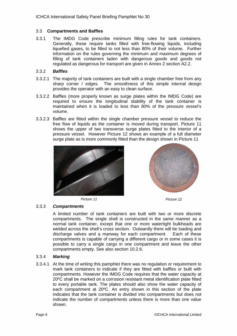
3.3.2.3 Baffles are fitted within the single chamber pressure vessel to reduce thefree flow of liquids as the container is moved during transport. Picture 11shows the upper of two transverse surge plates fitted to the interior of apressure vessel. However Picture 12 shows an example of a full diametersurge plate as is more commonly fitted than the design shown in Picture 11
3.3.3 Compartment
A limited numcompartmentsnormal tank cwelded acrossdischarge valvcompartmentspossible to cacompartments
3.3.4 Marking
3.3.4.1 At the time of wmark tank concompartments20ºC shall be mto every portaeach compartindicates thatindicate the nushown.
©ICHC
s
ber of tank containers are built with two. The single shell is constructed in the saontainer, except that one or more watertigthe shell’s cross section. Outwardly there wes and a manway for each compartment.is capable of carrying a different cargo or irry a single cargo in one compartment anempty. See also section 10.2.6.
riting this pamphlet there was no regulationtainers to indicate if they are fitted with b. However the IMDG Code requires that the
arked on a corrosion resistant metal identible tank. The plates should also show thement at 20ºC. An entry shown in this sethe tank container is divided into compartmmber of compartments unless there is mo
Picture 11
A International Limited
or more discreteme manner as aht bulkheads areill be loading and
Each of thesen some cases it isd leave the other
or requirement toaffles or built with
water capacity atfication plate fittedwater capacity of
ction of the plateents but does notre than one value
Picture 12

ICHCA International Safety Panel Briefing Pamphlet No 30
Page 7 ©ICHCA International Limited
3.3.4.2 New rules have been prepared and will come into effect with the publicationof the 2012 edition of the IMDG Code. These require tank containers wherethe shell or compartment is divided by surge plates into sections of not morethan 7,500 litres to have a letter “S” marked in either of the capacity sectionson the identification plate.
Note 1: There is no requirement to indicate the number of compartmentsinto which a tank container is divided
Note 2: The marking of the identification plate with a volume in thecompartment capacity or adding the letter “S” for shells andcompartments fitted with surge plates can not be easily seen bycontainer handlers except by close inspection of the identificationplate
Note 3: Tank containers with removable surge plates may be incorrectlymarked, i.e. the identification plate is marked with the letter “S”when the surge plates have been removed.
3.3.4.3 Tank containers filled with different dangerous goods in differentcompartments must display the appropriate marks and/or placards for eachhazard and for all dangerous goods carried.
3.3.5 Recording
3.3.5.1 There do not appear to be any mandatory requirements in the dangerousgoods regulations or regulations referring to non-regulated goods to indicatein any documentation accompanying the consignment as to whether tankcontainers are fitted with surge plates or divided into compartments.However there is a requirement to indicate the quantity of each dangerousgoods carried as part of that consignment.
3.3.5.2 As part of the guidance that this pamphlet offers, it is recommended that thenumber of spaces made within the tank container either by surge plates orcompartment is marked in the appropriate section of the Dangerous or NonRegulated Goods Note (see Annex 4 Figures A4.2 and A4.3).
3.3.5.3 Furthermore where the Goods Note has a space in which the number ofbaffles and/or compartments can be filled in. It is strongly recommendedthat an entry is made in these sections even to record that there is only asingle compartment or no baffles are fitted.
4 Tank Groups
4.1 Liquids
4.1.1 Tank containers built for liquids may:
have a stainless steel or mild steel pressure vessel shell;
be un-insulated or insulated
have heating or cooling equipment;
be lined with a protective coating

ICHCA International Safety Panel Briefing Pamphlet No 30
Page 8
Pict
4.2 Pressurised Liquefied Gases
4.2.1 Tank containers for pressurisedliquefied gases usually have a mildsteel pressure vessel shell. A fewspecialised tank containers forthese gases may have a stainlesssteel shell.
4.2.2 Where high ambient temperature ordirect sunlight can affect the cargothen a heat shield can be fittedabove the top of the pressurevessel (see Picture 13)
4.2.3 Rarely for tank containers, the pressure vessel sinsulated.
4.3 Powders and Granules
4.3.1 Tank containers for powders andgranules are generally lowpressure vessels manufacturedfrom aluminium alloys. An exampleis shown in picture 14.
4.3.2 The nature of the powder orgranule will dictate the design aswill the loading / unloading processin which the tank container is tooperate.
4.3.3 The discharge process for powders and granulesgases insomuch as the cargo may not “flow”. Therepowders and granules may be manufactured with hbuilt along the underside of the shell, or witmechanisms which facilitate the discharge.
4.3.4 Tank containers that carry powder and granules machassis / trailers
4.4 Tank Containers for Deeply Refrigerated Liquefied G
4.4.1 Some tank containers are designed and constructegases at extremely low temperatures, at around –20be referred to as “cryogenic tanks” within the frePicture 15 shows an example of a 20 ft cryrogenic ta
4.4.2 Due to the nature of thecargoes carried the level ofinsulation varies A typicalcryogenic tank container willhave an outer metal jacketsurrounding the pressurevessel. A near-perfectvacuum is created betweenthe outer metal jacket andthe pressure vessel; thisprovides the insulation.
©
Picture 13
u
hell may be totally un-
d
oh
y
0in
ICHCA International Limited
re 15
iffers from liquids andfore tank containers forpper discharge chutes
specialist discharge
be mounted on tipping
ases
d to transport liquefiedoC or lower. They mayght container industry.k
Picture 14
ICHCA International Safety Panel Briefing Pamphlet No 30
Page 9
4.4.3 In addition the space may be filled with an insulating material. Some tanksmay consist of a metal vacuum jacket, an outer shell containing a smallquantity of liquefied nitrogen and an inner shell intended to contain theactual liquefied gas to be transported.
4.4.4 These highly specialised tank containers represent less than 1% of theworldwide total. They do not have any refrigeration equipment (for exampleas reefer tank containers do).
5 Service Equipment, Fittings and Fixtures
5.1 The definition of service equipment is made in Annex 1 however in this sectionthe use of fittings will be used as a substitute and will encompass serviceequipment as defined by the IMDG Code and the closing devices for openingson tank shells which the IMDG Code considers to be part of the shell ratherthan as service equipment. Fittings are therefore defined as items attached tothe tank shell that perform a role that relates to the loading or discharge of thecargo, or the safety of the pressure vessel.
5.2 A separate term fixtures will be used to define all those items that are attachedto the frame or which perform a role that protects the pressure vessel.
5.3 Fittings (top of shell)
5.3.1 Access / Loading Hatch referred to as a Manway.
5.3.1.1 One or more manways are cut into the top of the shell and each consists ofa neck ring, a lid and a gasket seal. The neck ring will be fabricated from acompatible material to the shell and is a shaped pad that is welded to thepressure vessel.
5.3.1.2 Manways are provided to allow access by suitably qualified technicians andrepairers into the shell for periodic inspection. They are also often used onstandard tank containers as an opening for filling.
5.3.1.3 ISO 1496 / 3 states that the “size of the manway shall be a minimum of 500mm in diameter and shall be determined by the need for men and machinesto enter the tank to inspect, maintain or repair the inside. However thenature of the cargo and the designation of the tank will set the specificmanway lid configuration.
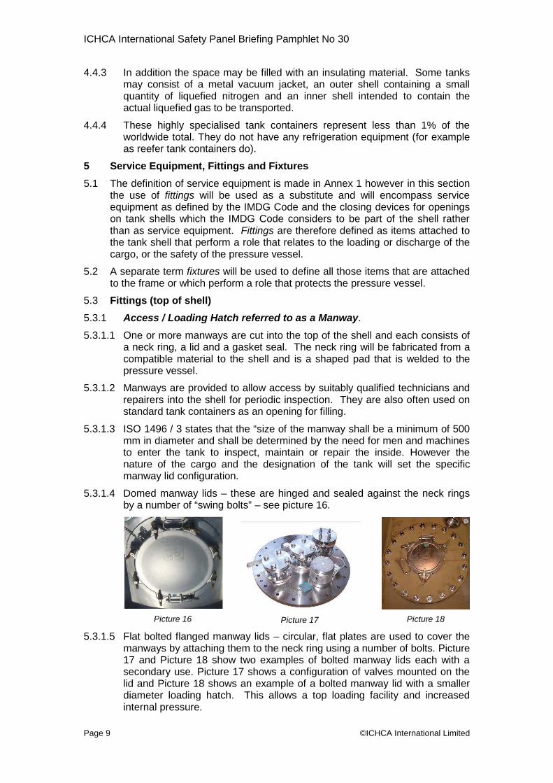
5.3.1.4 Domed manway lids – these are hinged and sealed against the neck ringsby a number of “swing bolts” – see picture 16.
5.3.1.5 Flat bomanwa17 andsecondlid anddiametinterna
lted flanged manway lids –ys by attaching them to thePicture 18 show two exam
ary use. Picture 17 shows aPicture 18 shows an examp
er loading hatch. This allol pressure.
Picture 16 P
©ICHCA International Limited
circular, flat plates are used to cover theneck ring using a number of bolts. Pictureples of bolted manway lids each with aconfiguration of valves mounted on the
le of a bolted manway lid with a smallerws a top loading facility and increased
icture 17 Picture 18

ICHCA International Safety Panel Briefing Pamphlet No 30
Page 10 ©IC
5.3.1.6 The number of swing bolts or flange bolts varies from type to type and thepressure rating of the tank. However when they are fully tightened theyshould form a pressure tight seal that will contain a pressure greater thanthe test pressure of the tank.
5.3.1.7 Where bolts are used in place of studs and nuts to secure the boltedmanway lid care needs to be taken at the time of manufacture, maintenanceand periodic testing to ensure that the bolts used are of the correct length sothat they may be fully tightened.
Note 1: See Annex 6 for more information on manway lid operation
Note 2: Once the container has been filled, opening the manway hatch / lidis generally not required until the tank container arrives at itsdestination.
Note 3: Many tanks have vacuum relief valves that are not sized to allowtanks to be discharged without opening the manway or otherfittings. If a tank container needs to be opened, this must be carriedout by a suitably qualified person.
5.3.2 Pressure Relief Valves
5.3.2.1 In general all tank containers whetherthey are designed for dangerous or nonregulated goods are fitted with one ormore spring loaded pressure reliefvalves which comply with therecommendations for their design, setpressures and venting capacity set forthin the United NationsRecommendations on the Transport ofDangerous Goods - Model Regulations(Orange Book). The pressure relief valves (see Picturetop space of the shell as close to the longitudinal andthey always remain in contact with the gas or vapoextremes of bad weather.
5.3.2.2 Pressure relief valves can come in two forms:
5.3.2.2.1 Valves may be high pressure only to prevent a buildmay result in the tank exploding, or,
5.3.2.2.2 Valves may be “twin acting” in that they are desiexcess pressure and to provide vacuum-relief inconditions arise in the shell. The vacuum relief ensunot implode due to low pressure.
5.3.2.3 Vacuum relief valves are also fitted on tanks thatatmospheric pressure to protect the tank against, for elow ambient temperature that may cause a reduced inte
P
HCA International Limited
19) are fitted in thelateral centre so thatur even during the
up of pressure that
gned to relieve bothcase partial vacuumres that the tanks will
normally operate atxample, the effect ofrnal pressure.
icture 19

ICHCA International Safety Panel Briefing Pamphlet No 30
Page 11 ©ICHCA International Limited
5.3.3 Frangible Discs
5.3.3.1 The IMDG Code requires that tank containerscomplying with portable tank instructions T5, T10,T12, T14, T16, T18, T19, T20, T22 and T23 (seeAnnex 5 paragraph A5.1.3) be fitted with a frangibledisc (see picture 20) in series underneath thepressure relief valve.
5.3.3.2 Frangible discs are fitted to provide:
protection to the pressure relief valve from thecorrosive effect of the substances and/ortheir vapours being carried
a guarantee that toxic vapours will only bereleased in extreme conditions
protection to the pressure relief valve fromany kind of malfunction caused by the cargo
additional security for higher hazard cargoes. They may also be usedto indicate an increase in the internal pressure within the tank that isstill below the pressure setting of the pressure relief valve
5.3.3.3 In addition to the frangible disc a “tell tale” indicator is required to provide ameans of monitoring the pressure between the frangible disc and thepressure relief valve.
5.3.3.4 The purpose of the “tell tale” indicator is todetect whether the frangible disc has broken dueto excess internal pressure. A typical “tell tale”indicator would be a pressure gauge connectedto the void between the frangible disc and thepressure relief valve which indicates current andmaximum pressure. Picture 21 shows anexample of the “tell tale” pressure indicator andthe frangible disc tail (arrowed).
5.3.3.5 If a change in pressure in the void is recorded the Shipper must benotified immediately
5.3.4 Vapour (Airline) Valves
5.3.4.1 During loading and discharge a means of preventing a build up of pressureor vacuum must be achieved. Such a build up could be prevented byleaving the manway lid open which in itself could be considered as a risk.Therefore a smaller opening can be provided in the vapour space to preventany such build up. Due to the hazardous nature of some cargoes openingthe pressure vessel to the atmosphere would constitute a severe risk. Thesolution is a closed (vapour recovery) system with more than one valve fittedwhich allows greater flexibility in load and discharge arrangements.
Picture 21
Picture 20

ICHCA International Safety Panel Briefing Pamphlet No 30
Page 12 ©ICHCA International Limited
5.3.4.2 The most common type of airline valve fitted to tank containers is the ballvalve (see Picture 22). Picture 23 shows a less common butterfly airlinevalve. However there are a large number of other valves used such as firesafe, plug valves, quick coupling assemblies, etc. One or more of the valvesmay be fitted with a pressure gauge. This gauge should not be confusedwith the pressure gauge associated with, and fitted to, pressure relief valves(see section 5.3.2).
Picture 22 Picture 23 Picture 24
5.3.4.3 Picture 24 shows a cluster of three ball type vapour valves with a smallpressure gauge; each is capped with a blanking / closing plate.
5.3.4.4 Vapour valves can vary in size from 1½” (38 mm) to 3” (75 mm).
5.3.5 Top Discharge / Outlets
5.3.5.1 Dangerous cargoes which may only be carried in tank containers complyingwith portable tank instructions T5, T8, T9, T10, T13, T14 and T19 to T22 canonly be discharged from the top. To provide flexibility in use during theirservice life, many tank containers are built to cater for both means ofdischarge, often with a bottom outlet and the provision for top discharge;effectively a pad attached to the pressure vessel and a blanking plate. Forcargoes requiring top discharge, tank containers fitted with bottom dischargeopenings must have the bottom outlet valves removed and the openingsblanked off by welding inside and out.
5.3.5.2 Conversion of bottom outlet tanks (see section 5.4.1) to top discharge ispermitted by the dangerous goods regulations. However, many tankcontainers intended for the transport of these dangerous goods will bemanufactured from the outset without any bottom openings. Often they are“dedicated” to just one dangerous good throughout their service life.
5.3.5.3 Rarely some tank containers may retain both their bottom discharge facilityand have top discharge possibilities. This is usually because although theuse of bottom discharge tank containers is allowed, customer preferencemay be to carry out top discharge operations.
5.3.5.4 Outwardly it is difficult to identify containers with top outlet / discharge. Thebottom discharge opening, if originally fitted, will be blanked over and avalve will be fitted over the top opening. There may be a sump pot in thebottom of the shell directly under the top outlet but this will only be visible onnon insulated tanks.
5.3.5.5 In practice a top outlet assembly consists of at least three valves withblanking plates. One of the valves is located over the top of a “siphon tube”(sometimes called a “dip tube”, “dip pipe”, “siphon pipe”) – see the valve onthe left in Picture 24. This is a vertical pipe, typically of 2 inches to 3 inches/40 mm to 75 mm in diameter which extends from the top of the shell

ICHCA International Safety Panel Briefing Pamphlet No 30
Page 13
(Picture 25) to close to the bottom (Picture 26). The length is critical formaximum discharge. Therefore they are not interchangeable betweendifferent tanks.
Picture 25 Picture 26
5.3.5.6 In the same area as the valve over the siphon pipe there will usually be atleast two other valves – see the two valves to the right in Picture 24. Theymay have the same diameter or one may be larger than the other. One ofthese will be intended to be used either for filling with a pipe or hosetemporarily bolted onto the flange once the covering plate has beenremoved or as a vapour return line. The second is intended to be usedeither as connection for pressure discharge or it, too, may be used as avapour return line.
5.3.5.7 The siphon tube is usually manufactured from the same material as the shellbut can be lined on the internal and external surfaces when the cargodemands this.
5.3.6 Spill Boxes
5.3.6.1 All of the above items can benormally found within the topoutlet or manway spill box.These are chambers, sometimesfitted with a hinged lid or lids(“storm door(s)”) that retain anyspills from the loading /discharge process. Picture 27shows an example of a top outletspill box.
5.3.6.2 Each spill box will have one ormore drains which will dischargeany liquids clear of the tankcontainer pressure vessel,cladding and insulation.
5.3.6.3 Drain tubes are generally surface mounted on neusually made of clear, see-through plastic so thamaterial can be seen and dealt with. They assirainwater, melt water from snow and ice and any pbox during loading. On some older designs the drathe insulation and cladding and cannot be seen. Incontainers, the outlets are located at the base ofincidents have been reported with these older tanleaking when liquid is seen dripping from the drainbe happening is that rain water, condensate or m
©ICHCA International Limited
wer containers and aret any liquid or solidifiedst with the drainage ofroducts spilt in the spillin tubes are covered by
the case of these tankthe tank. Many falsek containers said to betubes when all that mayelt water is running off,
Picture 27

ICHCA International Safety Panel Briefing Pamphlet No 30
Page 14 ©ICHCA International Limited
perhaps when the tank container has moved from an extremely cold climateto a warmer one causing snow and ice to melt.
5.3.6.4 On some tank containers the storm door(s) cover the pressure relief valve.The dangerous goods regulations require the vapour escaping from therelief valve to be discharged unrestrictedly. If the escaping vapour isflammable, there is a further requirement that the vapour must be directedaway from the shell in such a manner that it cannot impinge on it (seeparagraph 6.7.2.15.1 of the IMDG Code). Tank containers fitted with stormdoors which restrict the flow of escaping vapour and, particularly if the doorswill direct escaping flammable vapour back down onto the tank shell, shouldnot be accepted for carriage.
5.4 Fittings (bottom of shell)
5.4.1 Bottom Outlet Assemblies
5.4.1.1 Bottom outlet assemblies permit the filling but more importantly thedischarge of tank containers. The dangerous goods regulations provide forthree levels of protection on outlet assembly configuration depending on thenature of the cargo.
5.4.1.2 Bottom outlet not allowed
5.4.1.2.1 Certain cargoes must not be discharged from a bottom valve. These arecovered by the portable tank instruction designation T5, T8, T9, T10, T13,T14 and T19 to T22. There should be no bottom outlet arrangement ontanks carrying such cargoes, or where previously fitted, the valve(s) mustbe removed and the opening in the shell plated over as described inparagraph 5.3.5.1.
5.4.1.3 Two serial devices
5.4.1.3.1 For cargoes with a designation T1, T3 and T6 there must be at least twoserially mounted and mutually independent shut off devices fitted withinthe bottom valve assembly.
5.4.1.3.2 The first closure will often be a valve which closes inside the shell,usually call the “foot valve” (see Picture 29), or an externally closingbutterfly valve (see Picture 30). External valves are more usual in thecase of tank containers with just two closures. The second closure wouldthen generally be a threaded cap (see Picture 31) or a bolted blankflange.
5.4.1.3.3 However with only three cargo designations permissible with the twoserial device valve assembly, the majority of tank containers will be fittedwith three serial devices to increase the number of regulated cargoespermitted to be carried.
5.4.1.3.4 The dangerous goods regulations allow for products which easilycrystallise or which are viscous to be transported in bottom dischargeportable tanks with only two closures. However, competent authority isrequired when this option is used (see, for example, paragraph 6.7.2.6.2in the IMDG Code).

ICHCA International Safety Panel Briefing Pamphlet No 30
Page 15 ©ICHCA International Limited
5.4.1.4 Three serial devices
5.4.1.4.1 For cargoes with a designation T2, T4, T7, T11, T12, T15 to T18 and T23there must be at least three serially mounted and mutually independentshut off devices fitted within the bottom valve assembly.
Picture 29 Picture 30 Picture 31
5.4.1.4.2 The first (internal) closure will typically be a foot valve, (Picture 29),followed as closely as possible by a (external) butterfly valve (Picture 30)and finally by a threaded cap or a bolted blank flange (Picture 31).Picture 32 shows the assembly in-situ and Picture 33 the full assemblyshowing the spring loaded foot valve.
.
Picture 32
5.4.1.4.3 To operate the valve the threaded cap or blanking plate must be removedand the discharge hose attached. The two parts of the butterfly valvehandle are then squeezed together (see Picture 32) and the handlerotated through 90˚ in order to open it. Finally the foot valve is opened byrotating the handle forwards and downwards.
5.4.1.5 Tank fittings must only be operated by a suitably qualified technicianor operator who has in their possession the full details of:
the load status of the tank
the cargo
whether the tank is under pressure or not.
5.4.1.6 When the tank container is being transported all fittings which can bemanually closed, must be in their safe closed position and should be closedusing a customs or cleaning seal. Containers in transport found to haveany valve in the open position should be stopped and the shippernotified for instructions.
Picture 33

ICHCA International Safety Panel Briefing Pamphlet No 30
Page 16 ©ICH
5.4.1.7 Whilst most liquid tank containers are fitted with a butterfly valve as theexternal valve, other types may be encountered including ball valves, firesafe, plug valves, gate valves, diaphragm valves etc. Also, whilst thethreaded cap or blind flange represent what is fitted to the majority of tankcontainers intended for liquids other connections/closures may be foundsuch as various proprietary makes of quick couplings or dry-breakcouplings. They are acceptable alternatives on dangerous goods tankcontainers if they will totally prevent liquid flow when closed.
5.4.2 Remote Operating Devices
5.4.2.1 When three shut of devices are requiredthe first (foot valve) must be fitted with aremote operating device. This deviceconsists of steel cable, often plasticcoated stainless steel, or a rod whichleads from the foot valve along one side ofthe container (arrowed in Picture 34).Should there be an incident where theloading / discharge process should behalted, then the steel wire is pulled hard.The action of pulling the wire, or rod, willlift the foot valve operating handle over thecam position snapping the valve closed.
Picture 35 P
5.4.2.2 Picture 36 shows a second example of a spring loadedbehind the top access ladder that can be used to remvalve. Picture 35 shows the connection of the remote opfoot valve.
5.4.2.3 The international dangerous goods regulations have ntank containers to be fitted with a remote closurecompulsory to fit them on tank containers constructed f2002 onwards, i.e. second generation UN portable tanksgeneration tank containers constructed in the last cenwithout remote closures. There is no requirementregulations for these older tank containers to be retro-fitte
CA International Limited
icture 36
grab handle fittedotely close the footerating cable to the
ot always required. It only becamerom around 2001 –. There may be firsttury still in servicein the internationald with them.
Picture 34

ICHCA International Safety Panel Briefing Pamphlet No 30
Page 17 ©IC
5.4.3 Fusible Links
5.4.3.1 On closer examination Picture 35 showstwo cables attached to the foot valveremote operating mechanism. Thesecond cable is attached to a fusiblelink; these are usually fitted directlybehind the bottom discharge valveassembly.
5.4.3.2 This link is designed to break should itbe subjected to the higher temperaturesassociated with a fire. The link, arrowedin Picture 37, will break and the springwill then pull the foot valve remoteoperating mechanism closing the valve.
5.4.3.3 Fusible links are generally fitted to tank containeflammable liquids into the US. However many tankwithout this provision. The absence of the spring and lina hazard to the operator.
5.4.4 Discretionary Fittings
5.4.4.1 A large number of fittings may be fitted in addition to thThese include level indicators, low level alarms, highoperating systems, hydraulic operating systems, psystems, etc. The dangerous goods regulations prohiglasses” as a means of checking the level of liquids inexample, 6.7.2.16.1 of the IMDG Code.
5.4.4.2 Some tank containers may be fitted with “dip sticks”marking on it to measure the quantity of liquid in thelikely to be seen on old tanks as they are not often fitbuild tank containers. Others may have an “ullage bshaped piece of metal, held in place under the manwayMost modern tank containers have neither device.have a “calibration chart” fixed near the manway on wconverting depth of liquid to number of litres of cargo.
5.5 Fittings on T50 pressurised Liquefied Gas Tanks
5.5.1 The regulations are more complex with regards to liquethe working pressure is dependent upon any insulationtanks are designated as bare, sunshielded or insulated.
5.5.2 Liquid and Vapour Load / Discharge Assemblies
5.5.2.1 Liquefied gases by their very nature have to be loaded adifferent methods than liquids. Unlike liquid tanks, whbottom valve assembly is specified, the liquefied tankassemblies, both of which must consist of three semutually independent shut off devices. They should beand discharging purposes.
5.5.2.2 One of the valve assemblies will be for the liquid phaseother for the vapour phase and it is a mandatory requmarked accordingly. In order to ensure that the sepacargo are discharged separately and correctly theassemblies will be a different size.
HCA International Limited
rs carrying certaincontainers are built
k does not constitute
e mandatory fittings.level alarms, electricneumatic operatingbit the use of “sightside shells (see, for
, a metal stick withshell these are onlyted to more recentlyar”, a detachable T-lid or in the spill box.However, they mayhich a table is given
fied gas tanks in thatthat is provided. The
nd discharged usingere either a top or as will have two suchrially mounted and
used both for loading
of the cargo and theirement that each israte elements of the
liquid and vapour
Picture 37

ICHCA International Safety Panel Briefing Pamphlet No 30
Page 18 ©ICHCA International Limited
Picture 39
5.5.2.3 The dangerous goods regulations allowtwo different types of first, internal closingvalve, a stop valve for example in the formof a foot valve or “an excess flow valve”.This kind of valve is more commonly usedon tanks intended for the transport ofgases liquefied by overpressure.
5.5.2.4 On most T50 tank containers, the twovalve assemblies are located at one sideof the frame just above the bottomlongitudinal rail or a similar position onbeam tanks (see 3.1.4). On some T50tank containers the two valve assembliesmay be located in a recess at the midpoint of the rear end. This is usuallyprotected by a door (see Picture 38)
Some liquefied gas cargoes, such as chlorine, are not permitted to bedischarged from a bottom opening. In these cases all openings into the tankmust be above the liquid level.
5.5.3 Manways
5.5.3.1 The manway for liquefied gas tanks will generally be a bolted design, butunlike the standard liquid tanks it may be located in the head (end) of thecontainer or in the top
5.5.4 Sun Shields
5.5.4.1 Sun shields are fitted to tank containers carrying liquefied gas (T50). Theyare one of the designs approved for carrying this type cargo. Bare tanks arerare due to the significant increase in the required maximum allowableworking pressure which makes them uneconomic to produce.
5.5.4.2 Sunshield tanks (Picture39) are the mostpopular. They arerelatively inexpensive toproduce and the tareweight is less than thatof the higher pressureun-insulated tanks.
5.5.5 Pressure Relief Devices
5.5.5.1 T50 tank containers are fitted with pressure relief devices, usually pressurerelief valves, just like tanks for liquids. They have to be situated in the sameplace, i.e. as close to the lateral and longitudinal centre of the top of theshell. They are often taller than the pressure relief valves fitted to liquidstanks. This is to ensure they open sufficiently to allow sufficient vapour toescape.
5.5.5.2 Some tank containers such as those for toxic liquids will have to be fittedwith a bursting disc in series with the relief valve, just like liquid tanks.They have to be fitted with a tell tale pressure gauge which, just like liquidtanks must be monitored and reported to the shipper if it is showing that thefrangible disc has ruptured.
Picture 38

ICHCA International Safety Panel Briefing Pamphlet No 30
Page 19 ©ICHCA International Limited
5.5.6 Non-mandatory Fittings on T50 Tanks
5.5.6.1 Some T50 tank containers may be fitted with devices for measuring fillinglevels. Often these will be fitted in a recess similar to that described insection 5.3.6 in the rear end of the shell.
5.5.7 Tank fittings must only be operated by a suitably qualified technicianor operator who has in their possession the full details of:
the load status of the tank
the cargo
whether the tank is under pressure or not
5.6 Fittings on T75 Deeply Refrigerated Liquefied Gas Tanks
5.6.1 Liquid and Vapour Load / Discharge Assemblies
5.6.1.1 The loading and discharging assemblies on tanks intended for the transportof T75 deeply refrigerated liquefied gases are, by far, the most complex.Any number of valves and pieces of pipework that are usually found alongone side of these tank containers may be found within one or morecompartments. For each compartment there will be a connection for theliquefied gas to enter or leave the tank as well as for the vapour. These willhave three closures as with the tanks for liquids and pressure liquefiedgases. However they will be very different to the three closures on theother kinds of tank. This is due to the nature of the substances carried andthe design of the tanks which, as noted above in paragraph 4.4.2, usuallyhave a steel outer vacuum jacket surrounding the actual shell. In place ofthe foot valve fitted to liquid tanks, there are usually two external valves. Theinner valve is usually pneumatically operated. It requires a source ofpressure to be attached to it to open and hold it open.
5.6.2 Controls for Filling Levels
5.6.2.1 Additional valves may be fitted to control filling levels. It is commonplace forthese tanks to be fitted with internal vertical pipes rising from the floor nearlyto the top. Each one will be marked with the name of the gas for which itgives the maximum filling level. Once the shell has been filled to therequired mass, for example so as not to exceed the maximum permittedweight of its CSC approval, liquefied gas overflows. There will be valves andassociated pipework to control this process
5.6.2.2 These tanks are also usually fitted with flow gauges, usually circular, bywhich the filling level may be determined.
5.6.3 Pressure Raising Coils
5.6.3.1 Some of these tank containers can self-discharge. This is achieved bydiverting some of the liquefied gas into a pressure raising coil to turn it intogas and thereby raising pressure. This source of pressure is piped to thetop of the shell to push out the remaining liquefied gas. Tanks containerswith this possibility usually have a visible pressure coil, perhaps underneathor on the opposite side to the valve compartments.
5.6.4 Cryogenic Pumps
5.6.4.1 Some of these tank containers will be fitted with their own pumps located inthe compartments on the side. These pumps have to be cooled down tothe temperature of the liquefied gas inside the shell before they can beused. There will be associated pipework and valves on such tanks for the

ICHCA International Safety Panel Briefing Pamphlet No 30
Page 20 ©ICHCA International Limited
purpose of cooling the pumps down and for diverting the liquefied gas flowthrough the pump itself.
5.6.5 Pressure Bleed Valves
5.6.5.1 Tank containers are built to a given pressure rating which is linked to its“holding time” (see Annex 1 Definitions). Although every precaution possibleis taken to reduce the ingress of ambient heat into the tank shell, someheating from ambient sources will occur leading to boiling of a small amountof the liquid and consequential pressure rise (which should be well within thecapacity of the shell to withstand). Most T75 tank containers are fitted witha special automatic bleed valve to allow this low level pressure to drainaway during transport. It may be switched on and off manually. Whenswitched off, this minor rise in pressure is not automatically drained off.The latest edition of the IMDG Code in force at the time of preparation of thispamphlet does not contain any restriction concerning leaving the valve in anoperational condition though it is possible to interpret paragraph 7.1.8.1.3 ofthe IMDG Code to mean that this valve should be closed when T75 tankcontainers are carried on board sea-going vessels.
5.6.6 Vacuum Connection
5.6.6.1 There will be a connection on the outer surface of the vacuum jacket towhich gauges may be temporarily attached to measure the vacuum leveland/or to attach a pump to draw a near perfect vacuum between the jacketand the shell. The location of this connection will varies from design todesign.
5.6.7 Formation of Ice on Fittings and Pipework
5.6.7.1 It is possible for ice to form on fittings and pipework on T75 tank containerseven in the hottest and most arid of conditions. The formation of ice in thisway is not necessarily an indication that the tank container is leaking. Theice is formed from water vapour in the air condensing on the pipework, etc.
5.7 Fixtures
5.7.1 Walkways
5.7.1.1 A light weight walkway usually constructed of perforated aluminium plate isoften fitted on top of tank containers. It can be held in place by connectionsto one or both of the top side rails or to brackets attached to the end frameand pressure vessel.
5.7.1.2 Where the tank container is fitted with a walkway or access platform on topof the tank container. It should be of adequate dimensions in a single planeand with no tripping hazards and constructed of a non slip surface materialallowing suitable drainage.
5.7.1.3 ITCO recommends that it should be at least 460mm wide with slope lessthan 10° and be positioned to give safe access to the manway lid andsampling areas. Those tank containers that have a small diameter shell andrequire step down to access such areas should also have adequate flooringat the lower level.
Note: The walkway and supporting structure, including top side rails, arelightweight and only designed to support two persons. Overcrowding the walkway or excessive loading can result in it failingwith a severe risk of personnel falling.

ICHCA International Safety Panel Briefing Pamphlet No 30
Page 21 ©ICH
5.7.2 Access Ladders
5.7.2.1 The tank containers shown in this pamphlet generally have an access ladderbuilt into the end frame as shown in Picture 40 and Picture 41. It should beremembered that the ladder should only be used when suitable steps or anaccess platform adjacent to the tank container is not available. See section13.
Picture 40 Picture 41
5.7.3 Insulation
5.7.3.1 Insulated tank containers will generallybe enclosed in a preformed insulationmaterial or wrapped in insulation matting.Both types of insulation will be thencovered with either a GPR, stainlesssteel or an aluminium cladding jacket.
Note: The cladding / insulationmaterial is not designed towithstand a person standing onit. Picture 42 is an example ofthe warning signs typically fitted.Standing on the cladding maydamage it and there is a risk offalling.
5.7.4 Heating and Cooling
5.7.4.1 The majority of insulated tankcontainers will have some form ofheating capability. The principle meansof applying the heat is by steam, hotwater or hot glycol being piped throughheating coils welded directly onto theexterior of the barrel. Inlet and outletconnections should be clearly marked(see Picture 43).
5.7.4.2 Hot water/hot glycol heating systemshave a covered trough filled with theappropriate liquid. An electrical heating coil is immersedthermostat switches on an electric pump to circulatethrough the steam coil. Some tanks have a separateliquid. Glycol is often preferred because for example it htemperature than water.
P
Pi
icture 42
CA International Limited
in the trough and athe heated liquid
coil for the heatedas a lower freezing
cture 43

ICHCA International Safety Panel Briefing Pamphlet No 30
Page 22 ©ICHCA International Limited
5.7.4.3 Another means of applying heat is by electrical heating coils attached to theexterior of the barrel. There are a number of proprietary systems fitted totank containers so the operating instructions for the system concerned mustbe followed. In principle, at least two thermostats are provided on thesesystems, one of which registers the temperature of the heating coil and oneof which registers the temperature of the cargo.
5.7.4.4 All means of heating will be enclosed by the insulation and cladding.
Note: The operation of heating systems of tank containers, includingconnection and disconnection, repairs or maintenance, should onlybe undertaken by trained personnel.
5.7.5 Earthing Connections
5.7.5.1 It is recommended that vehicles used to transport tank containers laden withsubstances which could generate static electricity provide good electricalcontinuity from the tank shell to the vehicle and then to ground.
5.7.5.2 All tank containers approved for the transport of liquids meeting theflashpoint criteria of Class 3 (flammable liquids with a flashpoint temperatureof 60oC or below including any subsidiary danger of this kind andsubstances transported hot, at or above their flashpoint temperature), i.e.cargoes that are likely to be susceptible to ignition from static electricity,must be capable of being electrically earthed. This also applies to tankcontainers approved for the transport of flammable gases, whetherpressurised, liquefied or deeply refrigerated liquefied flammable gases.
5.7.5.3 Further, during loading, transport, cleaning and similar operations, measuresshould be taken to prevent electrostatic discharges. Picture 43 shows theearthing connection that should be connected to a suitable ground pointduring all loading and discharge operations.
ICHCA International Safety Panel Briefing Pamphlet No 30
Page 23 ©ICHCA International Limited
6 Tank Container Safety
6.1 General
6.1.1 ISO tank containers built to ISO 1496 / 3 and swap tanks built to CEN 1432and complying fully with the IMDG Code are inherently safe - there havebeen very few recorded examples where the pressure vessel has beendamaged sufficiently to permit a serious leak.
6.1.2 Tank containers shall not be offered for transport:
if containing liquids having a viscosity less than 2,680 mm2/s at 20°Cor at the maximum temperature of the substance during transport inthe case of a heated substance, with a degree of filling of more than20% but less than 80% unless the shells of portable tanks are dividedinto sections of not more than 7,500 litre capacity by partitions orsurge plates; (see also Annex 2 section A2.2.
with residue of substances previously transported adhering to theoutside of the shell or service equipment;
when leaking or damaged to such an extent that the integrity of theportable tank or its lifting or securing arrangements may be affected;and
unless the service equipment has been examined and found to be ingood working order. For certain dangerous substances, a lowerdegree of filling may be required.
6.1.3 Tank containers shall not be filled or discharged while they remain on boarda ship.
6.2 Design
6.2.1 Swap tanks may have thinner wall thickness than is required for thetransport of dangerous goods by sea. Shipping lines may be approached toship laden new swap tanks from non-European ports. So long as the cargocarried is classified as non-regulated or the shell wall thickness complieswith the IMDG Code requirements then the swap tank may be shipped. Seealso sections 6.1.2 and 12.3.
6.2.2 Designers of tank containers and legislators concerned with the carriage ofhazardous substances recognise that there is a need for fail safe featuresbuilt into any opening in the pressure vessel. These features are describedbelow:
6.2.3 Manways
6.2.3.1 The number of swing bolts or flange bolts varies from type to type and thepressure rating of the tank. However, when they are fully tightened theymust form a pressure tight seal that is at least as high as the test pressure ofthe tank
Note: Failure to tighten the swing or flange bolts correctly can result in thecargo leaking if the tank container is overturned.
6.2.3.2 The manway is protected from swipe damage by the spill box where one isfitted.

ICHCA International Safety Panel Briefing Pamphlet No 30
Page 24 ©ICH
6.2.4 Pressure Relief Valves
6.2.4.1 Pressure (or combined pressure / vacuum valves) provide safety againstover or under pressurisation conditions in the tank shells. Where thecontainer is carrying certain specified dangerous goods the pressure reliefvalve is fitted with a secondary security feature, the frangible disc, whichprevents an accidental release of the cargo’s vapour.
6.2.4.2 The degree of filling requirements (see Annex 2 section A2.2) ensures thatthere is always a vapour space at the top of the pressure vessel so that thepressure relief valve is exposed to the vapour only.
6.2.4.3 The pressure relief valve is protected from swipe damage by the spill boxwhere fitted.
6.2.5 Airline Valves
6.2.5.1 When not in use airline valves are blanked or capped off to preventaccidental operation of the valve.
6.2.5.2 The airline valve is protected from swipe damage by the spill box wherefitted.
6.2.6 Top Discharge Openings / Valves
6.2.6.1 When not in use top discharge openings and valves are blanked off toprevent accidental operation of the valve.
6.2.6.2 The top discharge fittings are protected from swipe damage by the spill boxwhere fitted.
6.2.7 Bottom Discharge Valves
6.2.7.1 The bottom discharge valve comprises of two or more separate and serialclosure methods as described in section 5.4.1. All pressure vessels arefitted with an internal foot valve that can retain the contents of the pressurevessel without any additional closure. External valve devices, such as theball or butterfly valves which provide the secondary closure device, areattached to the pressure vessel using fittings that are designed to fail withoutdamaging the pressure vessel.
6.2.7.2 It is of great importance that containerscarrying hazardous cargoes are fitted withthe correct bottom discharge valvecombinations. The internal foot valve mustbe fitted and closed during transportotherwise damage to the external valvescan result in the cargo being accidentallydischarged. Picture 44 shows an examplewhere the internal valve should retain thecargo following the shear section breaking.
Note: Should a shear force be applied to the bottom dthere is a risk that a small quantity of the cargTherefore when handling tank containers evemade to ensure that the tank container is landfree from objects that are likely to damageassembly.
CA International Limited
ischarge assemblyo may be released.ry effort should beed on level surface
the bottom valve
Picture 44

ICHCA International Safety Panel Briefing Pamphlet No 30
Page 25 ©ICHC
6.2.7.3 It is also important that all fittings, especiallydischarge valves, should not protrudeoutside of the envelope formed by the outerfaces of the corner fittings. Picture 45 showsa bottom discharge valve that has the end ofthe valve protruding outside of the endframe. There is a severe risk of the valvebeing damaged and some of the cargobeing released. Such containers shouldnot be shipped.
6.2.7.4 On large capacity tank containers, the outlet valve handoutside the end frame when open. It is most important thtank containers where this can happen are closed beforeand transported. Serious damage to outlet assemblshells may occur if handles protruding beyond the framexample by another container being placed next to it.
6.2.8 Tank Frames
6.2.8.1 The design of tank frames are suchthat the in the event of a catastrophicfailure of the frame as a result of thecontainer being knocked off a stack orthe tank container being involved in aroll-over accident, the pressure vesselwill remain intact as shown in Picture46
6.3 Operational Safety
6.3.1 Under no circumstances should lifting of tank contatruck be attempted. The only exception to this may bfor example, off-shore 10 foot tank containers fittdesigned and maintained fork lift pockets.
6.3.2 Many of the fittings and fixtures attached to the tank contoutside of the ISO envelope when they are open or erecte
Leaving temporarily fitted steam traps on the outcoils
Wrapping electric cables of heating systems aroustead of placing these in the proper holder or tray
Leaving temporary adaptors on airline connections
Not closing manway lids full after use
Not closing top outlet valve handles
Not closing airline valves on top of tanks
Waterlogged insulation material causing it to sag anthe allowable external dimensions
Collapsible handrails not properly stowed away
Note: Where any item protrudes outside of the econtainer must not be shipped
Picture 46
Picture 45
le often protrudesat outlet valves onthe tank is handledies and even tank
e are struck, for
A International Limited
iners by fork lifte in the case of,
ed with properly
ainer can protruded such as:
let pipes of steam
nd corner posts in
d/or bulge outside
nvelope the tank
ICHCA International Safety Panel Briefing Pamphlet No 30
Page 26 ©ICHCA International Limited
6.3.2.1 As stated in paragraph 5.3.6 spill boxes are fitted with a drain tube to allowwaste material to be drained. However it is important to note that liquidsescaping from these tubes are not always dangerous. There have been alarge number of false alarms raised because operators erroneously believedthat the tank container was leaking. However on closer examination theliquid was found to be melt or rain water.
6.3.3 Cryogenic Tanks
6.3.3.1 Cryogenic tanks do not have any refrigeration equipment but rely on thevacuum insulation to reduce heat gain and retain the gaseous cargo in aliquefied state. All such tanks have a maximum “holding time”, a maximumtime from filling before heat gain from ambient sources causes a pressurerise sufficient to open the pressure relief valves. The “holding time” willvary from tank to tank and should be made know to handlers and vesseloperators as exceeding the holding time can be dangerous.
6.3.4 Tank Container Heating
6.3.4.1 If steam heating is being undertaken, it is essential that suitable precautionsare taken to prevent anyone being scalded.
Each steam coil is designed to a specific maximum pressure.
Pressure should never be introduced into a steam coil in excess of itsmaximum pressure rating as there will be a risk of frangible the steamcoil and even causing serious damage to the tank shell.
6.3.4.2 Electrically heater tank containers do not have their own power source sothat a power cable has to be plugged into an external power source.
Most tank containers have a power cable but there is no standardlength for the cable.
It may be that extension cables have to be supplied to reach the powerpoint. Care must be taken that these are in good condition and of theappropriate power rating.
Most electrical systems are designed for operation from a 380 Voltthree phase supply, usually 32 amps. It is important to ensure that onlythe correct voltage and amperage power source is used.
Only the correct plug and socket should be used.
7 Documentation
7.1 When goods are offered for transport, shippers have to prepare documentationsuitable for the modes of transport and the type of the cargo. The form of thesedocuments, the particulars to be entered on them and the obligations theyentail may be fixed by international and national conventions, legislation,regulations and rules which apply to the different modes of transport.
7.2 As it would be impossible for this pamphlet to cover all these requirementsindividuals should make themselves aware of their local legislation, statutoryinstruments and regulations.
7.3 Documentation does not preclude the use of electronic data processing (EDP)and electronic data interchange (EDI) transmission techniques as an aid to, orin some cases in lieu of, paper documentation.
7.4 The examples shown in Annex 4 are intended to provide guidance of the detailrequired.

ICHCA International Safety Panel Briefing Pamphlet No 30
Page 27 ©ICHCA International Limited
8 Marking
8.1 Mandatory
8.1.1 ISO 6346 details the mandatory markings required for tank containers.Reference is drawn to the ICHCA International Safety Briefing Pamphlet 25– “An Illustrated Guide to Container Size and Type Codes”.
8.1.2 Under ISO 6346 all tank containers that are international intermodal loadingunits must carry:
a four capital letter code consisting of a three letter owner identificationcode and an equipment identifier “U”.
a serial number consisting of six Arabic numerals
a check digit
a size / type code. This is 22T6 for the majority of all 20 ft tankcontainers
the maximum gross and tare masses measured in kg and lb.
a warning of overhead electrical danger.
Note: The size/type code 22T6 relates to an ISO classification and doesnot correlate to the “T” codes set out in the IMDG Code.
8.1.3 Under the Convention for Safe Containers, all tank containers that areinternational intermodal loading units must carry a Safety Approval Platewith at least:
an approval reference,
the date of manufacture,
a manufacturer’s identification number,
maximum operation gross mass,
allowable stacking weight for 1.8g
transverse racking test load value
the next examination date or Approved Continuous ExaminationProgramme reference number
8.1.4 Under the Customs Convention for Containers, all tank containers that areinternational intermodal loading units must carry:
a means to identify the owner and their address, this may be anaddress plate or decal or the three letter owner identification coderegistered with BIC
a customs approval number
8.1.5 All international regulations require tank containers intended to carrydangerous goods to be inspected and tested at prescribed intervals. It isgood practice for all tank container shells that are designed to carrypressurised cargoes to be similarly inspected and tested. All tank containersmust carry:
the date of the initial hydraulic test
the date of each 2½ yearly intermediate inspection and test

ICHCA International Safety Panel Briefing Pamphlet No 30
Page 28 ©ICHCA Int
the date of each 5 yearly inspection and test.
8.1.6 Under the IMDG Code, all tank containers must carry:
the Proper Shipping Name (PSN) of the contents which shall bemarked on at least both sides of the tank container (see Annex 3)
any placards associated with the class of cargo carried
the UN number for the cargo carried (for example see Figure 1)
an Environmentally Hazardous Substances(Aquatic Environment) mark if appropriate(see Figure 2). For maritime transport thesesubstances are known as Marine Pollutantsand subject to the provisions of Annex III ofMARPOL 73/78. The mark shown in Figure2 is a recent addition to the IMDG Code
Previously the Marine Pollutant mark shownin Figure 3 was used to signal that the tank
container was carrying such a cargo. Thismark may be used until December 31st
2009.
8.1.6.1 Tank containers containing a substance that istransported in a liquid state at a temperatureequal to or exceeding 100ºC or in a solid state ata temperature equal to or exceeding 240ºC shallbear on each side and on each end the markshown in Figure 4.
8.1.6.2 In addition to the elevated temperature mark, themaximum temperature of the substanceexpected to be reached during transport shall bedurably marked on both sides of the tankcontainer, immediately adjacent to the elevatedtemperature mark, in characters at least 100 mmhigh.
Figure 1
F
F
Fi
igure 2
igure 3
ernational Limited
gure 4

ICHCA International Safety Panel Briefing Pamphlet No 30
Page 29
8.1.6.3 Under UIC, all tank containers that have amaximum gross mass equal to or greaterthan 34,000 kg must carry a super heavydecal (see Picture 47)
8.2 Optional
8.2.1 Calibration chart – a chart to provbased on a dip stick measurement
8.2.2 Do not walk decal – insulated contashown in Picture 48 affixed to ensstepped on. Stepping on it may be amaterial.
Picture 48 Pictur
8.2.3 Do not use fork truck decal. Pictureused.
8.2.4 Food Grade Cargo decal. Picturerectangle below is used to enclose th
8.3 Placards, Marks and Labels
8.3.1 There are specifications and minplacards. They must match the desigthe IMDG Code. Placards must be “square set at 45o. Each side must ba line alongside the edge of each pclass number of the hazard must beforming this number must be at least
Note 1: In most cases, where the cl6.1, it is not required to scorner. However, the dispoxidisers of Class 5.1 andcarried
Note 2: If a tank container is knodoes not display the classside, the tank container mu
©ICHCA International Limited
ide guidance on the volume of cargo
iners may have a decal similar to thature that the insulation cladding is not
slip hazard and damage the insulation
e 49 Picture 50
49 shows an example of the designs
50 shows a typical mark used. Thee name of the food stuff being carried.
imum dimensions specified for thens and colours shown in Chapter 5.2 ofdiamond” shaped i.e. in the shape of ae at least 250mm long. There must belacard inset by exactly 12.5 mm. Theshown in the lower corner. The digits
25 mm high
ass has a division number, for examplehow the division number in the lowerlay of this detail is mandatory whenorganic peroxides of Class 5.2 are
wn to carry dangerous goods andplacard on the front, rear and eachst not be accepted for transport.
Picture 47

ICHCA International Safety Panel Briefing Pamphlet No 30
Page 30 ©ICHCA International Limited
8.3.2 All the dangerous goods regulations require the marks and placards to beaffixed to tank containers in such a way as to be legible and durable. Allmarks and placards are required to be affixed in such a way as to remainlegible for up to three months in the sea.
Note: Tank containers with placards not completely adhering to thecontainer (for example, corners which are lifting up) or with airbubbles trapped under them (and therefore not durably marked)under them should not be accepted for transport.
9 Cargoes Carried
9.1 Tank containers are used for the transportation of bulk liquids, liquefied gases,deeply refrigerated (cryogenic) gases, powders and granules. Generally thetype of product will dictate the design of the tank container. However withineach tank group type the products may be regulated as hazardous goods ornon-regulated. Cargoes can be further designated as food grade (hazardousand non-regulated), kosher, and drug regulated, etc.
Note: Cargo handlers should be aware that some cargoes carried in tankcontainers can have a high specific gravity and thus even a smallvolume tank may carry a very heavy cargo.
9.2 Dangerous Goods
9.2.1 Tank containers can carry a variety of dangerous goods, and where the tankcontainer is made up of two or more compartments, the tank container maycarry more than one compatible dangerous good.
9.2.2 See Annex 5 for reference to dangerous goods.
9.2.3 All dangerous goods shall be referred to by their Proper Shipping Name(see Annex 3)
9.3 Non Regulated Goods
9.3.1 For the purposes of this pamphlet, non regulated goods refer to all of thoseproducts not covered by the IMDG Code, but that does not mean that someof them are not hazardous. Modes of transport other than by sea may havedifferent designations.
9.3.2 Examples of non regulated, non food goods that are typically transported intank containers are:
latex
linseed oil
drilling mud
emulsions
detergents
9.3.3 Examples of non regulated food goods that are typically transported in tankcontainers:
vegetable and other edible oils
wine
fruit juices (chilled and refrigerated)
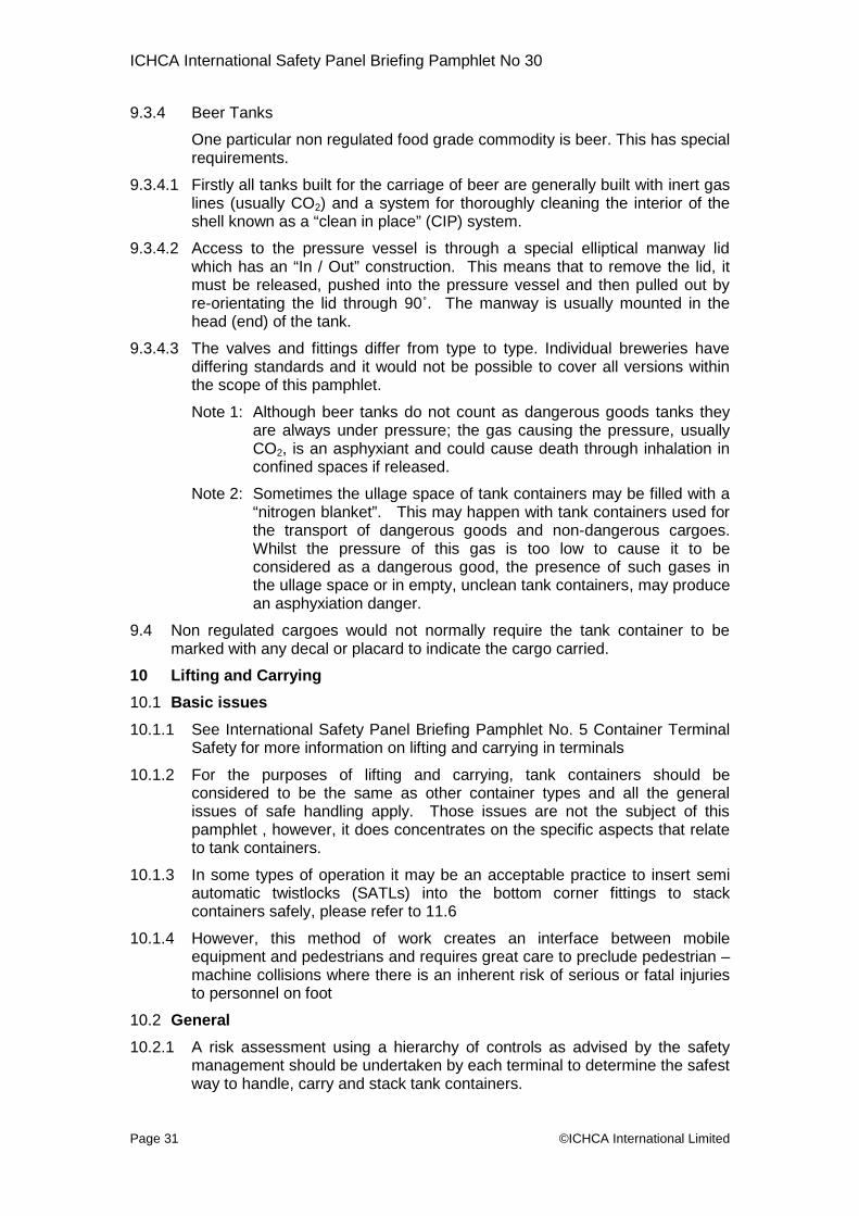
ICHCA International Safety Panel Briefing Pamphlet No 30
Page 31 ©ICHCA International Limited
9.3.4 Beer Tanks
One particular non regulated food grade commodity is beer. This has specialrequirements.
9.3.4.1 Firstly all tanks built for the carriage of beer are generally built with inert gaslines (usually CO2) and a system for thoroughly cleaning the interior of theshell known as a “clean in place” (CIP) system.
9.3.4.2 Access to the pressure vessel is through a special elliptical manway lidwhich has an “In / Out” construction. This means that to remove the lid, itmust be released, pushed into the pressure vessel and then pulled out byre-orientating the lid through 90˚. The manway is usually mounted in thehead (end) of the tank.
9.3.4.3 The valves and fittings differ from type to type. Individual breweries havediffering standards and it would not be possible to cover all versions withinthe scope of this pamphlet.
Note 1: Although beer tanks do not count as dangerous goods tanks theyare always under pressure; the gas causing the pressure, usuallyCO2, is an asphyxiant and could cause death through inhalation inconfined spaces if released.
Note 2: Sometimes the ullage space of tank containers may be filled with a“nitrogen blanket”. This may happen with tank containers used forthe transport of dangerous goods and non-dangerous cargoes.Whilst the pressure of this gas is too low to cause it to beconsidered as a dangerous good, the presence of such gases inthe ullage space or in empty, unclean tank containers, may producean asphyxiation danger.
9.4 Non regulated cargoes would not normally require the tank container to bemarked with any decal or placard to indicate the cargo carried.
10 Lifting and Carrying
10.1 Basic issues
10.1.1 See International Safety Panel Briefing Pamphlet No. 5 Container TerminalSafety for more information on lifting and carrying in terminals
10.1.2 For the purposes of lifting and carrying, tank containers should beconsidered to be the same as other container types and all the generalissues of safe handling apply. Those issues are not the subject of thispamphlet , however, it does concentrates on the specific aspects that relateto tank containers.
10.1.3 In some types of operation it may be an acceptable practice to insert semiautomatic twistlocks (SATLs) into the bottom corner fittings to stackcontainers safely, please refer to 11.6
10.1.4 However, this method of work creates an interface between mobileequipment and pedestrians and requires great care to preclude pedestrian –machine collisions where there is an inherent risk of serious or fatal injuriesto personnel on foot
10.2 General
10.2.1 A risk assessment using a hierarchy of controls as advised by the safetymanagement should be undertaken by each terminal to determine the safestway to handle, carry and stack tank containers.

ICHCA International Safety Panel Briefing Pamphlet No 30
Page 32 ©ICHCA International Limited
10.2.2 Arising from that assessment, the terminal should produce writtenprocedures for receiving and identifying tank containers and how to handlethem safely. Such procedures should include ensuring that containerhandlers are provided with all relevant information, instructions and trainingfor handling the various types of containers.
10.2.3 Training should be based upon the risk assessment and include alertnesson the part of the drivers of lifting and carrying equipment in regard to therisks.
10.2.4 All equipment used must be serviceable, having inspections and tests asrequired and must be suitable for the task.
10.2.5 Empty tank containers that last contained dangerous goods and have notbeen cleaned must be declared as EMPTY UNCLEANED or RESIDUELAST CONTAINED under the provisions of the IMDG Code.
10.2.6 All empty tanks must be treated as still carrying the last cargo unless a validcleaning certificate is available.
10.3 Handling Tank Containers fitted with Compartments
10.3.1 Tank containers built with two or more discrete compartments may present anumber of loading and handling issues:
The manways to each compartment may not be easily seen, or beobscured by the insulation and walkway, so container handlers maynot be aware that the tank container has more than one compartment.
Each compartment is capable of carrying a different cargo, each ofwhich may have a different mass which may affect the centre ofgravity of the tank container(see also Annex 2 section A2.1).
Where the tank container is carrying more than one dangerous goodthen the shipper must ensure that each are compatible and may becarried in the same tank container (although in differentcompartments).
10.3.2 When loading a tank container with two or more compartments, the shippershould ensure:
that each compartment is filled in line with the filling requirements (seeAnnex 2 section A2.2) especially if the capacity of the compartment isgreater than 7,500 litres.
that the cargo is loaded so that the tank container is balanced;
that where more than one dangerous good is being shipped, that eachdangerous goods has all appropriate marks and / or placards at eachend and on each side adjacent to the compartment carry the particulardangerous goods.
10.3.3 Balance can be achieved by:
loading an equal mass of each cargo into all the compartments so longas the filling requirements are maintained.
counterbalancing a single cargo with water (in a two compartment tankcontainer)
loading a single cargo into the central compartment where there arethree compartments

ICHCA International Safety Panel Briefing Pamphlet No 30
Page 33 ©ICHCA International Limited
loading two cargoes into the end compartments where there are threecompartments.
10.3.4 If the tank container cannot be balanced, then the heavier end must beplaced over the axles of a chassis / trailer when it is moved by road.
10.3.5 In all cases, the Dangerous Goods Note or Non Regulated Goods Note (seeAnnex 4 Section 4.2) should clearly indicate the contents and mass of anycargo loaded into each of the compartments.
10.4 Lifting and Carrying Appliances
10.4.1 Generally, most items of lifting and carrying equipment used in ports cansafely handle tank containers in the same way as other freight containers,i.e. by lifting from the top corner fittings via twistlocks in a lifting frameattached to a lifting appliance, and stacking corner fitting to corner fitting.
10.4.2 However, the lifting, carrying and stacking activities should comply with theprocedures specified after a general risk assessment has been undertaken.
10.4.3 There is a general need for drivers to be aware of the special nature of tankcontainers, the free surface effect when making turns and when coming toabrupt stops. The possible issues are detailed in Annex 2 section A2.4 FreeSurface Effect.
10.4.4 The safe lifting, carrying and stacking of tank containers is of the utmostimportance and is dependent on the appropriate risk assessment, theoperational procedures in place and the skill, ability and attitude of thedriver. In the unlikely event of hazardous substances leaking from thepressure vessel operators / drivers should immediately vacate the area andalert the appropriate emergency services.
10.4.5 Tank containers are required by law to comply with the regulationspertaining to the product carried. The level of construction is strictlyregulated and the risk of a leak of hazardous substances from a tankcontainer is far less than that from a dry freight container containing drumsor packages of hazardous material.
10.4.6 When handling tank containers operators should be aware of the followingexceptions:
Tank containers are not fitted with fork lift pockets and lifting ortransporting them using the tines of fork trucks is prohibited.
End frame attachments should not be used to lift/carry tank containers
ISO 3874 prohibits the use of side frames for all loaded tankcontainers.
Tank containers may be lifted by slings but the lifting equipmentshould be of such design that there is a vertical force at the cornerfittings, i.e. a chandelier spreader should be used.
Angled slings may be used when attached to the bottom cornerfittings only.

ICHCA International Safety Panel Briefing Pamphlet No 30
Page 34 ©ICHCA International Limited
10.4.7 Care should be taken when attaching manually operated spreaders used ina ship’s gear operation using a spring arm and chain system to lock/unlockcould become snagged on the top of the tanks
10.5 Internal Movement Vehicles
10.5.1 Only trailers fit for this purpose should be used to transport tank containersaround the terminal.
10.5.2 If using corner less trailers where the design of the container is such that thebottom side rail cannot be fully supported, i.e. for tank containers with araised side beam, the tank container should only be carried on such trailerswhere they have been specially adapted to ensure the safety of operatorsand handlers.
10.5.3 Two tank containers may be loaded on suitable trailers, including the cornerless types, provided they do not contain incompatible dangerous goods
11 Stacking Ashore
11.1 See International Safety Panel Briefing Pamphlet No. 5 Container TerminalSafety for more information on stacking and layouts
11.2 All handling locations should have procedures which should include a riskassessment for receiving and identifying special containers such as tankcontainers. The procedures should include special stacking requirements andcover segregation of incompatible goods.
11.2.1 The general segregation principles concerning dangerous goods in theIMDG Code apply equally to tank containers as to all other containerscarrying dangerous goods and should be followed
11.2.2 Containers carrying dangerous goods should not be placed at the end ofrows where they can be exposed to inter-sectional traffic.
11.3 There are two important messages associated with stacking tank containers:
Not all containers have the same stacking capability as required by ISO1496/3, and
All containers must be stacked corner fitting to corner fitting.
11.4 The Dangerous or Non Regulated Goods Notes (see Annex 4 Figure A4.2 andA4.3) should be supplied with the Maximum Superimposed Load shown in box18c. This value equates to the maximum load that can be placed on top of thecontainer – often referred to as the stacking capability. For ISO tank containersthe value will be at least 192,000 kg (see section 12.2).
11.5 When developing stacking plans within the risk assessment considerationshould be given to the following:
Ground surface
Surroundings
Segregation
Stack height
Visibility
Accessibility
Stability
Local weather conditions
Handling equipment
Human factors

ICHCA International Safety Panel Briefing Pamphlet No 30
Page 35 ©ICHCA International Limited
11.5.1 Tank containers carrying dangerous goods should be positioned so that theycan be clearly seen, protected and removed for isolation should an incidentoccur which may place persons in danger.
11.5.2 Tank containers should never be placed on rough or stony ground; caremust be taken such that contact by the full bottom surfaces of the fourbottom corner fittings is all that is possible. If this is not done, it is possible,for example, for the container to rest on the bottom outlet valves therebyrisking leakage.
11.5.3 Tank containers, for similar reasons should never be placed astride (out ofuse) rail tracks.
11.5.4 When handling tank containers every effort should be made to ensure thatthe tank container is landed on level surface free from objects that are likelyto damage the bottom valve assembly.
11.6 The ILO Code of Practice on Safety and Health in Ports states in paragraph6.3.2 10
“Wherever practicable tank containers should only be stacked one high.When it is necessary to stack tank containers more than one high it isrecommended that stacking cones be used in view of the differences oftank container frame designs. Tank containers carrying highly volatilesubstances should not be stacked over the pressure relief valves of highlyvolatile flammable substances.”
11.7 Tank containers may be stacked higher if adequate precautions are taken toprevent falling from the stack. This would be determined by carrying out a riskassessment of the area and the securing equipment to be used.
11.7.1 The design of tank containers varies as has been shown in section 2 of thispamphlet. When preparing a risk analysis for stacking any type of containeron top of a tank container, the operator should consider the risk associatedwith each design. Failure to stack a container correctly above a tankcontainer, i.e. corner fitting to corner fitting, may result in the stack toppling.Tank containers without full length top rails, such as the beam, collar andframe designs, may pose a greater risk of toppling however top rails of tankcontainers are not designed to support a fully laden mis-stacked container.
11.7.2 Tank Containers may be stacked up to a height that is determined by theterminal’s own risk assessment and to a height such that the maximumsuperimposed load is not exceeded. When completing the risk assessmentdue regard should be taken of the ILO Code of Practice shown in paragraph11.6 above.
11.8 General Stacking Considerations
11.8.1 The stacking of containers relies on the integrity and strength of the units.Stacking also relies on the transfer of the load through the corner postassemblies (comprising of the corner post, normally a square steel tube anda top and a bottom corner fitting, normally cast). No other component orassembly on any freight container type is designed or tested towithstand these loads. Therefore it is essential that containers arestacked corner fitting to corner fitting.

ICHCA International Safety Panel Briefing Pamphlet No 30
Page 36 ©ICHCA International Limited
Picture 51 Picture 52
11.8.2 Picture 51 shows two corner fittings stacked almost aligned and this shouldbe the objective of all operators involved with handling all types ofcontainers and tank containers in particular. However the three otherexamples (pictures 52, 53 and 54) show that it is possible for the containerstack to remain stable even though the containers are not positionedsquarely above one another.
Picture 53 Picture 54
11.8.3 However the units, when stacked without their corner fittings aligned with theunit above / below, are being subjected to forces that they have not beentested against. Under the ISO 1496 series of standards, containers aretested with a 38 mm longitudinal and a 25 mm transverse offset between thecorner fittings. The risk of failure increases as the offset increases.
Therefore it is essential that all containers are stacked with the cornerfittings aligned as closely as practicable.
11.8.4 Many of the tank container units are fitted with incorrectly named “mis-stacking plates” as identified by the arrows in pictures 52 and 55. Whilethese have been added to increase the surface area of the corner fittingsthey cannot be relied upon for supporting a stack of laden containers.
11.8.5 The design and height of top and bottom rails on tank containers varygreatly. These components are not designed for stacking.
11.8.5.1 Top rails, where present, are generally manufactured from 3 mm thick rolledhollow section tube. These are often only there as a means of connectingthe walkway and are therefore only expected to support the weight of twomen..
11.8.5.2 The strength of the top rails and the even loads imposed by their heightdifferentials means there is a risk of failure associated with stackingcontainers on these components

ICHCA International Safety Panel Briefing Pamphlet No 30
Page 37 ©ICHCA
11.8.5.3 Pictures 55 and 56 show two designs of bottom corner fitting / bottom railconnection but others can be seen in the preceding sections. There is aserious risk of failure if tank containers are stacked using the bottom rail.
Picture 55 Picture 56
12 Stowage on ships
12.1 With a few notable exceptions the stowage of tank containers on board ships isno different than the stowage of any other container. Like all containers,consideration should be given to the gross mass of the tank container and itsimpact in any given stowage location, on the stability of the ship.
Note: The gross weight of tank containers is often rated higher than themajority of other containers for example up to 36,000 kg. The actualvalue will be shown in box 19 of the Dangerous or Non RegulatedGoods Note (see Annex 4, Figures A4.2 and A4.3).
12.2 Allowable Stacking Weight
12.2.1 The allowable stacking weight represents the maximum superimposed loadthat any container can be subjected to and isoften referred to as the stacking capability orstack height (when converted to a number ofcontainers). The allowable stacking weight /superimposed weight should be entered ontoThe Dangerous or Non Regulated Goods Note(see Annex 4 Figures A4.2 and A4.3) in box 18c.
12.2.2 The stacking capability of a tank container canalso be found on the Safety Approval Plate fittedon the rear of the container and generally formspart of a larger plate as arrowed in Picture 57.
12.2.3 The Safety Approval Plate will carry important data whicassist in the safe handling of tank containers. Firstly theWeight will be shown. In Picture 58 it is marked 34,000 kgshown in Picture 59 for a different unit, it is 36,000 kg.
12.2.4 The second pieceof important data isthe allowablestacking weight,which is shown as72,000 kg in theexample (Picture58).
Picture 58
h is provided toMaximum Grossand on the plate
Picture 57
International Limited

ICHCA International Safety Panel Briefing Pamphlet No 30
Page 38 ©ICHCA International Limited
12.2.5 The different designs for the tank supporting frames determine the stackingcapability of the tank container. Most ISO tank containers are built to theprovisions of ISO 1496 part 3 which will require that the container is built towithstand a superimposed load of 192,000 kg. This value is the equivalentof eight superimposed containers with an average mass of 24,000kg.
12.2.6 Table 1 shows the stacking configuration for a selection of averagesuperimposed container masses. Note the mass of the bottom container isnot taken into account when calculating the superimposed average mass.
Average grossmass (kg) ofcontainers
24,000 30,480 32,500 34,000 36,000
Stack height 8 over 1 6 over 1 5 over 1 5 over 1 5 over 1
Ladencontainer stack
12.2.7 There are few international tank containers in service today with a maximumgross weight rating of 30,480 kg so, as shown in Table 1, the maximumconfiguration will generally be five fully laden tank containers stacked overthe bottom one (total six per stack).
12.2.8 However swap tanks have a different design and therefore a differentstacking capability. The wider designed width of these units means thatthere is a step between the corner posts and the top corner fittings. Pictures59 and 60 show examples of the step in the post.
Picture 59 Picture 60
12.2.9 Containers with a step of this nature will generally have a lower stackingcapability. The container may be marked with a warning decal that indicatesthat there is a reduced stacking capability.
12.2.10 The safety approval plate example shown in Picture 58 is such a tankcontainer where the maximum gross value of 36,000 kg and a reducedallowable stacking weight of 72,000 kg. This means that only two similarand fully laden containers can be stacked above it. .
12.2.11 When considering a stack of tank containers, the maximum superimposedload of the bottom container will dictate the total stack height. A containerwith the stacking capability of the units shown in Picture 58 can only havetwo containers placed above it, whether they are the stronger internationalor the weaker European loading unit. On the other hand a tank container
Table 1

ICHCA International Safety Panel Briefing Pamphlet No 30
Page 39 ©ICHCA International Limited
with a maximum superimposed load of 192,000 kg may have up to five unitsloaded on top, unless a European unit is placed directly above it or third inthe stack, in which case the stack height would be limited to three or fourabove it respectively.
12.3 Tank Container Width
12.3.1 Swap tanks are generally wider than ISO tank containers. However thedesigns of these two types of tank container are difficult to distinguish,especially when seen from a distance. The consequence of attempting toload a swap tank into a standard ISO cell guide may result in the containerbecoming jammed.
12.3.2 The additional width of the swap tank may also prevent it from being stowedin lower positions adjacent to other ISO containers as the spacing of thedeck fittings are generally too close to be able to accommodate theadditional width. Swap tanks may require stowing where there are noadjacent containers.
12.3.3 Because of the width and the possible reduced stacking capabilities,shippers who wish to move laden or empty swap tanks on deep sea routesmust confirm that the ship is able to carry them. Furthermore the ship’splanner must be advised when the container “slot” is booked and thecontainer delivered to the terminal.
12.4 Segregation
12.4.1 Containers, including tank containers, carrying dangerous goods shall besegregated in line with the IMDG Code.
12.4.2 Containers carrying a cargo or its vapour that could adversely affect othersusceptible cargoes should be stowed in separate holds.
12.5 Emergency Response and Clean Up
12.5.1 In the most severe case the pressure vessel could develop a leak or bepunctured.
12.5.2 Such a release could represent a significant emergency response challengeso consideration must be given to the stowage location.
12.5.3 A commodity that is environmentally hazardous or a hazardous pollutingsubstance is probably best stowed below deck where leaks or dischargescan be contained within the hold of the ship. However it must be recognisedthat this may also present a hazard to the crew and/or emergency servicespersonnel.
12.5.4 Commodities that are extremely difficult to clean-up (for example latex)should be stowed on deck.
12.5.5 Cryogenic liquids should never be stowed below deck.
12.5.6 Any bulk liquid released into the hold regardless of cargo carried mayproduce a significant clean-up challenge.
12.5.7 The guidance in dealing with release, spillage, fire or exposure to dangerousgoods given in IMO’s Emergency Response Procedures for Ships CarryingDangerous Goods (EmS) and Medical First Aid Guide for Ships (MFAG)should also be followed.

ICHCA International Safety Panel Briefing Pamphlet No 30
Page 40 ©ICHCA International Limited
12.5.8 In summary the following are important when accepting a tank container andplanning for their stowage on board a ship:
Ensure the shipper / operator has not over or under filled the tank.See section 4.2.1.9 in the IMDG Code for specific guidance in thisregard
Ensure the shipper / operator has not filled the tank so that thecombined mass of the cargo and the tare of the tank containerexceeded the rated maximum gross mass of the container (see 12.2.3,Annex 1 Definitions and Annex 4 section A4.2.4).
Plan the stow based on the tank’s gross mass and on the possibleneed to segregate its contents from other dangerous goods in thestow.
Consider the tank container as a closed container for the purposes ofsegregation but keep in mind that tank containers have relief devicesthat may release vapours during a voyage.
Note: For substances with clear of living quarters in column 16 ofthe Dangerous Good List, in deciding stowage, considerationshall be given to the possibility that leaking vapours maypenetrate the accommodation, machinery space and otherwork areas. It should be kept in mind that vapours may passdown companionways and other openings into living spacesand work areas. Bulkheads, for example, between holdsand engine rooms must be kept hermetically sealed.
Consider the potential for a large spill and any attendant emergencyresponse or clean-up activity that may be necessary.
Tank containers loaded with a hazardous substance and stowed ondeck but not intended for discharge at the terminal should not be left inthe path of other containers or hatch covers being moved in the samebay. In such a case, the tanks should be either moved to another bayor, if that is not practical, placed at a safe location on the terminal as are-handle(s).
In planning stowage, consideration should be given to the plug-inarrangements necessary for certain cargoes in tank containers whichneed heating or cooling.
13 Access to Tank Container Tops and Working at Height
13.1 All tank containers where access to the interior can only be gained through atop opening or where the cargo is loaded through a hatch in the top of thecontainer will be fitted with a means of climbing onto the container top.However these access means often will have restricted and in some casesincomplete rungs / steps.

ICHCA International Safety Panel Briefing Pamphlet No 30
Page 41 ©ICHCA In
Picture 61 Picture 62
13.2 Tank containers will have a ladder built into the rear frame, some of which canbe clearly discernable as a ladder, see Picture 61, while others may appear asa climbing frame see Picture 62.
13.3 Where access is required to the top of the container,they will be marked with a warning decal as shown inPicture 63. The decal indicates a warning from alloverhead hazards and power cables in particular.Operators when deciding whether to access the topof the container should make themselves aware of allpotential hazards directly overhead and immediatelyadjacent to the container. This warning is particularlyimportant for operations in rail transfer depots butmay affect other handling operations.
13.4 However the ladders built into the tank container should only bea means of access to the top of the container in an emergency,of climbing onto the top of the container entails a risk of slippOperational access to tank container tops should be mademobile steps or from a gantry.
13.5 When the container is loaded onto a chassis the bottom of the lamuch as 1,200 mm, and the top of the container as much aground. Furthermore on some designs of chassis the containeinclined with the front end elevated which would mean that theinclined towards to the operator.
13.6 The steps / rungs are generally manufactured from steel or alumbe slippery in the cold and wet. Operators can easily miss tclimbing these ladders.
ternational Limited
considered asas the processing and falling.using suitable
dder can be ass 3.8 m off ther will be slightlyladder would be
inium and canheir step when
Picture 63
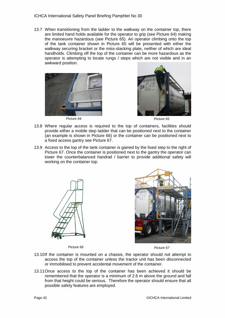
ICHCA International Safety Panel Briefing Pamphlet No 30
Page 42
13.7 When transitioning from the ladder to the walkway on the container top, thereare limited hand holds available for the operator to grip (see Picture 64) makingthe manoeuvre hazardous (see Picture 65). An operator climbing onto the topof the tank container shown in Picture 65 will be presented with either thewalkway securing bracket or the miss-stacking plate, neither of which are idealhandholds. Climbing off the top of the container can be more hazardous as theoperator is attempting to locate rungs / steps which are not visible and in anawkward position.
13.8 Where reguprovide eith(an examplea fixed acce
13.9 Access to thPicture 67.lower the cworking on
13.10If the contaaccess theor immobilis
13.11Once accerememberefrom that hepossible saf
©ICH
Picture 64
lar access is required to the top of containers, facilities shoulder a mobile step ladder that can be positioned next to the container
is shown in Picture 66) or the container can be positioned next toss gantry see Picture 67.
e top of the tank container is gained by the fixed step to the right ofOnce the container is positioned next to the gantry the operator canounterbalanced handrail / barrier to provide additional safety willthe container top.
iner is mounted on a chassis, the operator shtop of the container unless the tractor unit hased to prevent accidental movement of the conta
ss to the top of the container has been achd that the operator is a minimum of 2.6 m aboveight could be serious. Therefore the operator shety features are employed.
Picture 65
Picture 66
CA International Limited
ould not attempt tobeen disconnectediner.
ieved it should bethe ground and fallould ensure that all
Picture 67

ICHCA International Safety Panel Briefing Pamphlet No 30
Page 43 ©IC
13.12Handrails
13.12.1 ITCO recommend that hand rails are not fitted to tank containers - seealso “Prevention of falls from ISO Tank Containers conforming to ISO 1496– 3” issued by ITCO (www.itco.be)
13.12.2 Where the tank container is fitted from new with a permanently installedhandrail, the handrail should be a minimum height of 1,100 mm in the raisedposition with at least one intermediate rail.
Note 1: When handrails are installed on tank containers they must provideeffective fall protection around all sides of the access and workarea. Single handrails do not provide this and additional measuresmust be taken to prevent falls.
Note 2: Handrails that are not securely retained when not in use canincrease the risk of handling failures.
13.13Use a fall arrest system, by far the bestitem of personnel safety equipment thatcan be employed. Operators should wearan approved harness and attachthemselves to the overhead cables. InPicture 68 a number of “T” shapedstanchions are positioned about the areawhere an operator will work on the top ofthe container. The connecting overheadcables have counterbalanced arrest drums
supported from them to which the operatorwill attach their harness.
13.14Do not overcrowd the top of the container. The walkwaand strength. Furthermore with too many people on themoving about can be hazardous.
14 Inspecting Tank Container Interiors
14.1 Under no circumstances should stevedores, dockwtransport workers or customs officials, who havetrained and equipped, open or enter any tank concontainer is declared as “empty”.
14.2 When considering inspecting the interior of the tank coconsidering opening and entering a vessel which is anshould be remembered that the tank container will havecargoes, some of which may be hazardousor cause an oxygen depleted atmosphere(i.e. little or no oxygen).
14.3 Furthermore it is common practice thattank containers once they have beendischarged may be only partially cleaned orfilled with inert gases to be finally cleanedat the point of loading of the next cargo. Insuch cases the valves and hatches may besealed during such transport as shown inPicture 69 (see also Annex 5 section A5.3)
ys are limited in sizetop of the container
orkers, ships crew,not been properlytainer, even if the
ntainer, one is reallyenclosed space. Itcarried a variety of
Picture 68
HCA International Limited
Picture 69

ICHCA International Safety Panel Briefing Pamphlet No 30
Page 44 ©ICHCA International Limited
14.4 In judging whether a tank container is safe to enter, it should be born in mindthat the vapours of many liquid chemicals and gases are heavier than air sothat pockets of such gases can exist even in the upper air space is consideredto be safe,
14.5 Therefore inspecting the interior should not be done until the container hasbeen certified to be safe to enter. This requires a test by a specialist and theuse of personal protection equipment by properly trained operatives.
14.6 If the interior of the tank container requires inspection or even if the accesshatch needs to be opened then this should only be done by, or under thesupervision of, specialist operatives normally found at tank cleaning stations.
Under no circumstances should stevedores, dockworkers, ships crew,transport workers or customs officials who have not been properlytrained and equipped open any tank container even if the container isdeclared as “empty”.

ICHCA International Safety Panel Briefing Pamphlet No 30
Page 45 ©ICHCA International Limited
Annex 1 Definitions
BIC means Bureau International des Containers et du Transport Intermodal
Cargo Transport Unit (CTU) means a road freight vehicle, a railway freightwagon, a freight container, a road tank vehicle, a railway tank or a portabletank. Used as an alternative to Intermodal Loading Unit (ILU)
Dangerous Goods mean the substances, materials and articles covered bythe IMDG Code. In some countries the term Hazardous Materials is in theirlocal regulations in place of Dangerous Goods. In many other countries theterm Dangerous Substances is used. Except in the United StatesDangerous Substances can be considered as having the same definition asDangerous Goods
Frangible disc is also known in the tank container industry as a bursting discor sometimes a rupture disc.
Gross Weight, more properly the gross mass, means the sum of the tareweight plus the weigth of the cargo loaded. The weight of the fully ladencontainer must not exceed the maximum gross weight shown on the SafetyApproval Plate. See also Maximum Gross Weight.
IMDG Code means the current edition of the International MaritimeDangerous Goods (IMDG) Code adopted by the Maritime Safety Committeeof International Maritime Organisation (IMO).
Intermodal Loading Unit (ILU) means a container that can be interchangedbetween all modes of surface transport using common handling equipmentand without intermediate reloading. See also Cargo Transport Unit (CTU).
Intermodal transport means a system of transport in which the cargo can beinterchanged between all modes of surface transport using commonhandling equipment and without intermediate reloading.
Manway means a port, usually circular, cut into the top of the shell whichenables access to the tank’s interior. Each manway will be fitted with aclosing hatch or cover. Also known as a manhole or accessway.
Marine Pollutants means substances which are subject to the provisions ofAnnex III of MARPOL 73/78, as amended.
Maximum Gross Weight the term used within the Convention for SafeContainers, 1972 and this pamphlet means the total permitted weight of thetank container and the payload. The value is shown on the Safety ApprovalPlate and the identical number shall be shown on the rear end of thecontainer. Maximum Gross Weight is also be referred to as Max Gross,MGW or Rating but more properly should be referred to as Maximum GrossMass
Maximum Holding Time means the maximum time from filling before heatgain from ambient sources causes a pressure rise sufficient to open thepressure relief valves. The holding time will vary for each tank design andthe existing ambient conditions. It should be made known to containerhandlers and ship operators as exceeding the holding time may increase therisk of cargo escaping.
Multimodal transport means a journey involving multiple means of transport,originally used to describe road and rail transport. Multimodal is a term used
ICHCA International Safety Panel Briefing Pamphlet No 30
Page 46 ©ICHCA International Limited
within Europe to describe road and rail transport modes and is used in placeof Intermodal transport within the IMDG Code.
Portable Tank means a multimodal tank used for the transport of substancesof class 1 to 9. The portable tank includes a shell fitted with serviceequipment and structural equipment necessary for the transport ofdangerous substances. The portable tank shall be capable of being filledand discharged without removal of its structural equipment. It shall possessstabilising members external to the shell, and shall be capable of being liftedwhen full. It shall be designed primarily to be loaded onto a transport vehicleor ship and shall be equipped with skids, mountings or accessories tofacilitate mechanical handling. A portable tank for the transport of non-refrigerated liquefied gases of class 2 shall have a capacity of more than450 litres.
Service Equipment as used in the IMDG Code means measuring instrumentand filling, discharge, venting, safety, heating, cooling and insulatingequipment.
Shell means the part of the portable tank which retains the substanceintended for transport (tank proper), including openings and their closures,but does not include service equipment or external structural equipment.Shells may be of two basic types, either:
“atmospheric” with little or no capability of withstanding an internalpressure higher than the external pressure; or
“pressure vessel” which have the capability of withstanding a higherinternal pressure than the external pressure acting upon the outersurface.
International regulation governing the transport of dangerous goods at seaprohibits the use of “atmospheric” tank shells and in practice there are veryfew of these types of tanks in service.
Structural Equipment means the reinforcing, fastening, protective andstabilising members external to the shell.
Tank Container means a portable tank with fittings, structural capabilitiesand dimensionsthat enable it to be handled and secured by the same meansas any ISO or EN configured container.
Tare means the weight of the tank container in its unloaded state. Itincludes the shell. service and structural equipment.
UIC means Union International des Chemins de Fer and UIC Rules refers torules for European rail transport.
Ullage means “the amount by which a container, such as a bottle, cask, ortank, falls short of being full”

ICHCA International Safety Panel Briefing Pamphlet No 30
Page 47 ©ICHCA International Limited
95
1 + α(tr - tf)
Annex 2 Centre of Gravity, Ullage and Degree of Filling
A2.1 Centre of Gravity
A2.1.1 Different types of tank may have a different centre of gravity, dependent onthe design and the amount of steel in the framework.
A2.1.2 Typically an empty tank will have a lower centre of gravity than will a loadedtank. However a loaded tank will have a dynamic centre of gravity that shiftsmarginally longitudinally and laterally and upwards as the contents surgefore or aft or from side to side. When the tank is correctly filled this shouldnot affect stability (see section A2.4 Free Surface Effect).
A2.1.3 When handling tank containers, operators should be aware that on vehicles,including handling equipment, where a dynamic centre of gravity may affectthe stability of the vehicle, the loaded tank container should be transportedso that the combined centre of gravity (vehicle and tank container) is as lowas practicable.
A2.2 Degree of Filling
A2.2.1 Prior to filling, the shipper shall ensure that the appropriate tank container isused and that the tank container is not loaded with cargo that, in contact withmaterials of the shell, gaskets, service equipment and any protective linings,is likely to react dangerously with them to form dangerous products orappreciably weaken the materials.
A2.2.2 Portable tanks shall not be filled in excess of the maximum degree of fillingspecified in A2.2.3 to A2.2.8. The applicability of A2.2.3, A2.2.4 or A2.2.8 toindividual substances is specified in the applicable portable tank instructions(see 0 section A5.1.3).
A2.2.3 The maximum degree of filling (in %) for general use is determined by theformula:
Degree of filling =
A2.2.4 The maximum degree of filling (in %) for liquids of class 6.1 and class 8, inpacking groups I and II, and liquids with an absolute vapour pressure ofmore than 175 kPa (1.75 bar) at 65°C, or for liquids identified as marinepollutants is determined by the formula:
Degree of filling =
97
1 + α(tr - tf)

ICHCA International Safety Panel Briefing Pamphlet No 30
Page 48 ©ICHCA International Limited
d15 – d50
35d50
dr
df
A2.2.5 In these formulae, α is the mean coefficient of cubical expansion of the liquidbetween the mean temperature of the liquid during filling (tf) and themaximum mean bulk temperature during transport (tr) (both in °C). Forliquids transported under ambient conditions, α could be calculated by theformula:
α =
in which d15 and d50 are the densities of the liquid at 15°C and 50°C,respectively.
A2.2.6 The maximum mean bulk temperature (tr) shall be taken as 50°C exceptthat, for journeys under temperate or extreme climatic conditions, thecompetent authorities concerned may agree to a lower or require a highertemperature, as appropriate.
A2.2.7 The provisions of A2.2.3 and A2.2.4 do not apply to portable tanks whichcontain substances maintained at a temperature above 50°C duringtransport (such as by means of a heating device). For portable tanksequipped with a heating device, a temperature regulator shall be used toensure the maximum degree of filling is not more than 95% full at any timeduring transport.
A2.2.8 The maximum degree of filling (in %) for solids transported above theirmelting points and for elevated temperature liquids shall be determined bythe following formula:
Degree of filling = 95
in which dr and df are the densities of the liquid at the mean temperature ofthe liquid during filling and the maximum mean bulk temperature duringtransport respectively.
A2.2.9 In simple terms the degree of filling for tank containers without surge platesshould be greater than 80% (see Annex 2 section A2.2) and no greater than:
97% for general dangerous goods, or
95% for liquids in class 6.1 and class 8 in packaging group I and II
though the actual value for each substance is unlikely to be as high as thesevalues.
A2.2.10 The filling level for liquefied gas containers is referred to as the filling ratio.This takes into account various parameters for temperature and pressure.

ICHCA International Safety Panel Briefing Pamphlet No 30
Page 49 ©ICHCA International Limited
A2.2.11 The degree of filling should be filled in the appropriate box on the Dangerousor Non Regulated Goods Note (see Annex 4, figure A4.2 and figure A4.3
Note: Tank containers shall not be offered for transport:
with a degree of filling, for liquids having a viscosity of less than 2,680mm2/s at 20°C, or,
at the maximum temperature of the substance during transport in thecase of a heated substance, of more than 20% but less than 80%unless the shells of portable tanks are divided, by partitions or surgeplates, into sections of not more than 7,500 litre capacity;
A2.2.12 Minimum Degrees of Filling - Worked Example
Example: A substance, non-viscous, is a dangerous good. It has a liquiddensity of 1.51 at 20ºC. It is loaded at ambient temperature. Ashipper wishes to ship 20,000 kg consignments in tankcontainers. The only suitable tank containers do not havebaffles. What capacity of tank should be chosen from a selectionof tank containers with capacities 15,000 litres, 17,000 litres or20,000 litres to carry the substance?
Step one: Calculate the volume (in litres) of the substance the shipperintends to load at the filling temperature:
Cargo Net Mass= Volume (litres)
Liquid Density
20,000 kg= 13,245 litres
1.51
Step two: The maximum size of an un-baffled tank which can be used tocarry this non-viscous substance is calculated by:
Volume (litres) x 100= Theoretical tank size
80
13,245 x 100= 16,556 litres
80
If a tank container without baffles is selected with a greatercapacity than 16,556 litres, it will be less than 80% full for thisparticular substance.
Solution: From the available ISO tank containers the 15,000 litre one mustbe used.

ICHCA International Safety Panel Briefing Pamphlet No 30
Page 50 ©ICHCA International Limited
95
1 + α(tr - tf)
A2.2.13Maximum Degrees of Filling – Worked Example
Paragraphs A2.2.3, A2.2.4 and A2.2.8 cover three situations for differingsubstances:
maximum filling of lesser danger liquid substances loaded at ambienttemperatures
maximum filling of greater danger liquid substances or with a highervapour pressure
maximum filling of molten dangerous substances (carried above theirmelting point temperature)
Example1: The substance ACRYLONITRILE, STABLIZED, Class 3,Subsidiary Hazard 6.1, Packing Group I, UN 1093 is to beshipped in tank containers. A shipper wishes to ship 22,500 kg.The largest suitable tank container available has a capacity of26,000 litres. Can this consignment be accepted? The substancehas a liquid density at the filling temperatures:
of 0.812 at 15ºC (filling temperature); and
of 0.772 at 50ºC (highest possible temperature).
Step 1 Determine the volume represented by 22,500 kilos of thesubstance at the filling temperature:
Cargo Net Mass= Volume (litres)
Liquid Density
22,500 kg= 27,709 litres
0.812
Conclusion: A 26,000 litre tank container is too small for the shipper’spreferred consignment. The shipper must be informed as to themaximum permitted quantity that can be loaded in this tankcontainer.
Step 2 From the Dangerous Goods List (column 14 – Portable tankprovisions) UN 1093 this substance require TP2 and TP13provisions to be applied
IMDG Code paragraph 4.2.5.3 indicates that TP13 requires selfcontained breathing apparatus shall be provides when thissubstance is transported (see Table A5.2), and TP2 directs threader to 4.2.1.9.3 of the Code (see A2.2.4).
Degree of filling =

ICHCA International Safety Panel Briefing Pamphlet No 30
Page 51 ©ICHCA International Limited
d15 – d50
35d50
0.812 – 0.772
35 x 0.772
95
1 + 0.0014893(50-15)
where α is the coefficient of cubical expansion, tr is the referencetemperature to be taken as 50ºC and tf is the filling temperature,in this case 15oC.
Step 3 Calculate the coefficient of cubical expansion (see A2.2.5):
α =
α =
α = 0.0014803
Step 4 Enter the coefficient of cubical expansion into the formulaobtained at Step 2:
Degree of filling =
Degree of filling = 90.29%
Solution: The maximum degree of filling permitted by the IMDG Code of atank container laden with this substance is 90.3%.
This means for a 26,000 litre tank container, filled withACRYLONITRILE, STABLIZED, .only 90.29% of its capacity canbe used which equates to 23,478 litres (26,000 x 0.0929(90.29%)).
The shipper originally wanted to ship 22,500 kg of thissubstance, but this weight of the cargo was:
1. equated to a volume larger than the tank available(27,709 litres – Step 1)
2. is restricted to 23,478 litres by the IMDG Code and theavailable tank container.
The shipper an convert the volume back to net mass bymultiplying the available volume by the liquid density:
23,478 litres x 0.812 = 19064 kg (80.72% of the original cargomass)

ICHCA International Safety Panel Briefing Pamphlet No 30
Page 52 ©ICHCA International Limited
A2.3 Ullage
A2.3.1 In the case of tank containers, ullage makes up the difference between fulland the degree of filling which is defined for hazardous cargoes as per theprevious section.
A2.3.2 For non regulated cargoes there are no formal requirements for ullage or thedegree of filling. However similar rules should apply, with each tankbetween 80 and 97% filled. However many containers are shipped with theresidue of the cargo on their way to be cleaned. In these cases the containershould not be more than 20% full.
A2.3.3 Tank containers must not be shipped unless they comply with theappropriate regulations for cargo fillings as explained in this pamphlet.Under no circumstances should incorrectly loaded tank containers beaccepted for any form of transport; road, rail or sea.
A2.4 Free Surface Effect
A2.4.1 The free surface effect is one of several mechanisms where an incorrectlyfilled tank container on a rail wagon or chassis / trailer, can become unstableand roll-over. It refers to the tendency of liquids to move in response tochanges in the attitude of cargo holds, decks, chassis, wagons or liquidtanks in reaction to operator-induced motions.
A2.4.2 ADR, IMDG and UN all have recommendations about the filling of tankcontainers (see also paragraph 3.3.1). All tank containers should be filled tocomply with these regulations and therefore the surging of the cargo as thetank container is moved should usually not adversely affect the cargohandler.
A2.4.3 Containers which are loaded correctly in line with the degree of fillingdetailed in Annex 2 section A2.2 will not be affected by free surface effect.However drivers of tractor / trailer combinations carrying a container with ahigh centre of gravity should be especially careful when changing lanes andturning tight corners, especially if travelling relatively fast or making sharpmanoeuvres.
A2.4.4 Drivers of cargo handling equipment and hauliers should not transport tankcontainers which are greater than 20% and less than 80% filled. In suchcases they would experience:
Noticeable surging of the cargo if the tank container is filledbetween 70 and 80%
Severe surging of the cargo if the tank container is filled between60 and 70%
Dangerous surging of the cargo if the tank container is filledbetween 40 and 60%, to the extent that the tank container will beunstable once it is in motion.
Note: ITCO recommends that tank containers which are not filledcorrectly should be stopped and the Shipper notified immediately.

ICHCA International Safety Panel Briefing Pamphlet No 30
Page 53 ©ICHCA International Limited
Annex 3 Proper Shipping Name
A3.1 Proper Shipping Name
A3.1.1 The Proper Shipping Names of the dangerous goods are those listed inchapter 3.2, Dangerous Goods List of the IMDG Code. Synonyms,secondary names, initials, abbreviations of names, etc. have been includedin the Index to facilitate the search for the Proper Shipping Name (see Part5, Consignment Procedures of the IMDG Code). Where, in this pamphlet,the term "Proper Shipping Name" is used, it is the "correct technical name"required by regulation 4 of Annex III of MARPOL 73/78, as amended.
A3.1.2 The Proper Shipping Name is that portion of the entry in the DangerousGoods List most accurately describing the goods. It is shown in upper-casecharacters (plus any numbers, Greek letters, 'sec', 'tert', and the letters m, n,o, p, which form an integral part of the name). An alternative ProperShipping Name may be shown in brackets following the main ProperShipping Name (such as ETHANOL (ETHYL ALCOHOL)). Portions of anentry appearing in lower case need not be considered as part of the ProperShipping Name but may be used.
A3.1.3 When conjunctions such as "and" or "or" are in lower case or whensegments of the name are punctuated by commas, the entire name of theentry need not necessarily be shown in the transport document or packagemarkings. This is the case particularly when a combination of several distinctentries is listed under a single UN Number. Paragraphs A3.1.4 to A3.1.6illustrate the selection of the Proper Shipping Name for such entries.
A3.1.4 UN 1057 LIGHTERS or LIGHTER REFILLS - The Proper Shipping Name isthe most appropriate of the following:
LIGHTERS
LIGHTER REFILLS
A3.1.5 UN 2583 ALKYLSULPHONIC or ARYLSULPHONIC ACIDS, SOLID withmore than 5% free sulphuric acid - The Proper Shipping Name is the mostappropriate of the following:
ALKYLSULPHONIC ACIDS, SOLID
ARYLSULPHONIC ACIDS, SOLID
A3.1.6 UN 2793 FERROUS METAL BORINGS, SHAVINGS, TURNINGS orCUTTINGS in a form liable to self heating. The Proper Shipping Name is themost appropriate of the following:
FERROUS METAL BORINGS
FERROUS METAL CUTTINGS
FERROUS METAL SHAVINGS
FERROUS METAL TURNINGS.
ICHCA International Safety Panel Briefing Pamphlet No 30
Page 54 ©ICHCA International Limited
A3.1.7 Proper Shipping Names may be used in the singular or plural asappropriate. In addition, when qualifying words are used as part of theProper Shipping Name, their sequence on documentation or packages isoptional. Commercial or military names for goods of class 1, which containthe Proper Shipping Name supplemented by additional text, may be used.
A3.1.8 Many substances have an entry for both the liquid and solid state (seedefinitions for liquid and solid in the IMDG Code paragraph 1.2.1), or for thesolid and solution. These are allocated separate UN numbers which are notnecessarily adjacent to each other. Details are provided in the alphabeticalindex, e.g.:
NITROXYLENES, LIQUID - 6.1 UN 1665
NITROXYLENES. SOLID - 6.1 UN 3447.
A3.1.9 Except for self-reactive substances and organic peroxides and unless it isalready included in capital letters in the name indicated in the DangerousGoods List, the word STABILIZED shall be added as part of the ProperShipping Name of a substance which without stabilization would beforbidden from transport due to it being liable to dangerously react underconditions normally encountered in transport for example TOXIC LIQUID,ORGANIC, N.O.S., STABILIZED. When temperature control is used tostabilize such substances to prevent the development of any dangerousexcess pressure, then:
For liquids: where the Self Accelerating Dew composition Temperature(SADT) is less than or equal to 50°C the provisions of IMDG Codeparagraph 7.7.5 shall apply;
For gases: the conditions of transport shall be approved by thecompetent authority.
A3.1.10 Hydrates may be transported under the Proper Shipping Name for theanhydrous substance.
A3.2 Generic or "Not Otherwise Specified" (N.O.S.) entries
A3.2.1 Generic and "Not Otherwise Specified" Proper Shipping Names that areassigned to special provision 274 in column 6 of the Dangerous Goods Listshall be supplemented with the technical or chemical group names unless anational law or international convention prohibits its disclosure if it is acontrolled substance. For explosives of class 1, the dangerous goodsdescription may be supplemented by additional descriptive text to indicatecommercial or military names. Technical and chemical group names shall beentered in brackets immediately following the Proper Shipping Name. Anappropriate modifier, such as "contains" or "containing" or other qualifyingwords such as "mixture", "solution", etc., and the percentage of the technicalconstituent may also be used. For example: "UN 1993 FLAMMABLELIQUID, N.O.S. (contains xylene and benzene), 3, PG II".
A3.2.2 The technical name shall be a recognized chemical or other name currentlyused in scientific and technical handbooks, journals and texts. Trade namesshall not be used for this purpose. In the case of pesticides, only ISOcommon name(s), other name(s) in the WHO Recommended Classification

ICHCA International Safety Panel Briefing Pamphlet No 30
Page 55 ©ICHCA International Limited
of Pesticides by Hazard and Guidelines to Classification, or the name(s) ofthe active substance(s) may be used.
A3.2.3 When a mixture of dangerous goods is described by one of the "N.O.S" or"generic" entries to which special provision 274 has been allocated in theDangerous Goods List, not more than the two constituents which mostpredominantly contribute to the hazard or hazards of a mixture need to beshown, excluding controlled substances when their disclosure is prohibitedby national law or international convention. If a package containing a mixtureis labelled with any subsidiary risk label, one of the two technical namesshown in brackets shall be the name of the constituent which compels theuse of the subsidiary risk label.
A3.2.4 Examples illustrating the selection of the Proper Shipping Namesupplemented with the technical goods for such N.O.S. entries are:
UN 2902 PESTICIDE, LIQUID, TOXIC, N.O.S. (drazoxolon)
UN 3394 ORGANOMETALLIC SUBSTANCE, LIQUID, PYROPHORIC,WATER-REACTIVE (trimethylgalllum).
A3.3 Marine Pollutants
A3.3.1 For generic or “not otherwise specified” (N.O.S.) entries, the proper shippingname shall be supplemented with the recognised chemical name of themarine pollutant.
A3.3.2 Examples illustrating the selection of the Proper Shipping Namesupplemented with the recognised technical name of the goods for suchentries are shown below:
UN 1993, FLAMMABLE LIQUID, N.O.S. (propyl acetate di-n-butyltin-2-ethylhexanoate), class 3 PGIII (50ºC c.c.) MARINE POLLUTANT
UN 1263, PAINT (triethylbrnzene), class 3 PGIII (27ºC c.c.) MARINEPOLLUTANT

ICHCA International Safety Panel Briefing Pamphlet No 30
Page 56 ©ICHCA International Limited
Annex 4 Documentation
A4.1 Booking Request
A4.1.1 The documentation chain starts with the shipper or the freight forwardermaking a Booking Request (see Figure A4.1) to use tank containers totransport their product to the destination.
A4.1.2 Every request should include a unique Shipper’s Reference which will beused on all future documentation and correspondence.
A4.1.3 Every shipment made in tank containers will require the shipper to bookeither tank containers owned by the shipping line or to use their own(shipper’s own) tank and book “slots”. Additionally the shipper will need tospecify the size of the tank container (normally 20 ft), the volume of thepressure vessel, the average weight of the cargo, whether heating or coolingis required and what power / heat source is required to operate it and anyother unique features or requirements such as holding time.
A4.1.4 Tank containers can be shipped in three states, loaded with a cargo, un-cleaned with a residue of the previous cargo or cleaned.
A4.1.5 The Shipper will need to advise the shipping line of the cargo that is to becarried. If the cargo is classified as Dangerous Goods then the shipper willneed to provide the UN number, the Proper Shipping Name, the primary andsecondary hazard class(es), the packing group and, if applicable, the flashpoint of the product being carried.
A4.1.6 The port of loading/port of discharge sections deal with the deep / short seavoyage itself, identifying the container yard (CY) where the tank containeroriginates, the planned port of discharge and the planned dates for theloading and discharge.
A4.1.7 The steamship line will also record its booking number for the booking.
A4.1.8 Some countries may require details of the customs office to be recorded
A4.1.9 The section for special instructions should be used to indicate stowage andhandling requirements and any other information that would be useful to theshipping line stevedores and transport companies.

ICHCA International Safety Panel Briefing Pamphlet No 30
Page 57 ©ICHCA Inte
© ITCO 2008
To: Date:
Attn: Booking Ref:
To be quoted on all correspondence and invoives
We would like to book the following containers: Volume (lt)
Container will be
Loaded
Un cleaned / Residue
Clean
Product name
Description
Hazard Class Packing Group: Flash Point:
EMS
Export Customs
Telephone: Fax:
Special Requirements / Instructions
Other Remarks
Contact Phone / Fax No.:
Company email:
Port of oncarriage date:
Booking Request
Number of Shipper Owned Tank Containers
Length Heating / Cooling
Voyage
Precarriage date:
Port of loading date:
Port of entry date:
Steamship Line Contract
Number of Shipping Line Tank Containers
Approximate Cargo weight per container
Vessel
Pre carriage location / Receiving CY
Port of Loading
Port of Entry / Discharge
Port of on carriage location / Delivery CY
See A4.1.3
See A4.1.4
See A4.1.5
See A4.1.7
See A4.1.8
See A4.1.9
Figure A4.1
Other feature
See A4.1.2
See A4.1.6
rnational Limited
/

ICHCA International Safety Panel Briefing Pamphlet No 30
Page 58 ©ICHCA International Limited
A4.2 Dangerous Goods Note
A4.2.1 One of the fundamental requirements of a transport document for dangerousgoods is to convey the essential information relative to the hazards of thegoods. Therefore, unless otherwise exempted or required in the IMDGCode, the document should carry all the basic information appertaining to aconsignment of dangerous goods. An example of a Dangerous Goods Noteis shown in Figure A4.2.
A4.2.2 Exporter (Shipper) and Consignee information
Box 1 the name and address of the exporter – the company fromwhom the cargo originates
Box 2 a unique reference number and the same as shown on thebooking request
Box 4 a unique reference generated by the exporter relating to thetotal shipment, i.e. all containers in the shipment.
Box 5 if the transport is being arranged by a freight forwarder, thenthey can add their own reference number into this box.
Box 6 the name and address of the company who will be receivingthe goods at the end of the transport chain.
Box 6a if the transport is being arranged by a freight forwarder, theirname and address should be entered into this box.
Box 7 the name and address of the shipping company (Carrier)who will complete the maritime portion of the journey.
A4.2.3 Shipping Marks (Box 14)
For dangerous goods, the transport document shall contain the followinginformation in the order presented below:
The UN Number preceded by the letters “UN” e.g. “UN 1098”;
The Proper Shipping Name (PSN), as described in Annex 3, includingthe technical name enclosed in parenthesis, as applicable e.g. “UN1098 ALLYL ALCOHOL”;
The primary hazard class or, when assigned, the division of the goods,including Class 1, the compatibility group letter. The words “Class” or“Division” may be included preceding the primary hazard class ordivision numbers e.g. “UN 1098 ALLYL ALCOHOL class 6.1”;
Subsidiary hazard class or division number(s) corresponding to thesubsidiary risk label(s) required to be applied, when assigned, shall beentered following the primary hazard class or division and shall beenclosed in parenthesis. The words “Class” or “Division” may beincluded preceding the subsidiary hazard class or division numberse.g. “UN 1098 ALLYL ALCOHOL class 6.1 (class 3)”;
Where assigned, the packaging group for the substance which may bepreceeded by “PG” e.g. “UN 1098 ALLYL ALCOHOL class 6.1 (class3) PG I”

ICHCA International Safety Panel Briefing Pamphlet No 30
Page 59 ©ICHCA International Limited
Figure A4.2

ICHCA International Safety Panel Briefing Pamphlet No 30
Page 60 ©ICHCA International Limited
A4.2.4 Every document should carry at least the following container information:
Box 14a Enter the weight of the cargo measured in kg. If there isonly one compartment in the tank container enter the samevalue in Box 18a “Total net mass”. Otherwise Box 18ashould be th sum of the weight of the different cargoescarried.
Box 14b Enter the volume of the cargo measured in m3. If there isonly one compartment in the tank container enter the samevalue in Box 19a “Total cube”. Otherwise Box 19a should beth sum of the volume of the different cargoes carried.
Calculate the degree of filling – Total cube (Box 19a) / tank volume(Box 17a).
Box 15 Enter the container four letter prefix, e.g. ABCU.
Box 15a Enter the six numbered serial number and a single numeralcheck digit, e.g.123456 7.
Box 15b Enter the ACEP reference number e.g. ACEP NV 11/07 orNext Examination Date (NED) that is marked on thecontainer.
Box 16 Enter the serial number for each of the seals applied to thecontainer in the order, bottom valve, top discharge valve,manway hatch;
Box 17 Enter the container size and type code that is shown on thecontainer, e.g. 22T0
Box 18 Enter the Tare weight / mass (recorded in kg) as shown onthe Safety Approval Plate
Box 18c Enter the maximum superimposed load Allowable stackingweight / mass) as shown on the Safety Approval Plate (seeSection 12.2)
Box 19 Calculate the sum of the tare and cargo weight and enter itinto this box. The value should be less than the MaximumGross Weight / Mass shown on the Safety Approval Plate(see Picture 59, Section 12.2)
Box 19c Enter the number of compartments the tank container isfitted with. It is highly recommended that an entry is alwaysmade in this Box even of there is only a singlecompartment.
A4.2.5 Declaration (Box 20)
A4.2.5.1 Box 20 shall be completed by a responsible officer of the company who isresponsible for loading the container with the cargo. The responsibleofficer declares that the tank container has been loaded with the cargostated in the volumes recorded.
A4.2.5.2 It shall include the Company name and the name of the responsibleofficer written in BLOCK CAPITALS.

ICHCA International Safety Panel Briefing Pamphlet No 30
Page 61 ©ICHCA International Limited
A4.3 Non Regulated Goods Note
A4.3.1 Non regulated goods refer to those goods that are not covered by section 3of the IMDG Code. They may be referred to as non hazardous or foodgrade, but there are instances where non regulated cargoes may behazardous or dangerous e.g. goods which are combustible or which maycause serious disruption if released into the environment. An example isshown in Figure A4.3.
A4.3.2 The form is basically the same except there is no reference to the IMDGCode or Dangerous Goods declaration.
A4.3.3 Other information required on the form is of use to stevedores and othercargo handlers.
A4.4 Periodic Inspection Reports
A4.4.1 Every container is subject to periodic examinations. These examinationsare carried out every 2½ and 5 years. The 5 year test will include a fullpressure test every five years
A4.4.2 A Test Inspection Report is issued by an inspection organisation certified bya Classification Society. Additionally, tank containers are subject to andneed to be periodically examined in accordance with the requirements of theInternational Convention for Safe Containers (CSC).

ICHCA International Safety Panel Briefing Pamphlet No 30
Page 62 ©ICHCA International Limited
Figure A4.3
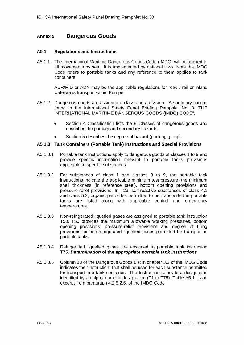
ICHCA International Safety Panel Briefing Pamphlet No 30
Page 63 ©ICHCA International Limited
Annex 5 Dangerous Goods
A5.1 Regulations and Instructions
A5.1.1 The International Maritime Dangerous Goods Code (IMDG) will be applied toall movements by sea. It is implemented by national laws. Note the IMDGCode refers to portable tanks and any reference to them applies to tankcontainers.
ADR/RID or ADN may be the applicable regulations for road / rail or inlandwaterways transport within Europe.
A5.1.2 Dangerous goods are assigned a class and a division. A summary can befound in the International Safety Panel Briefing Pamphlet No. 3 “THEINTERNATIONAL MARITIME DANGEROUS GOODS (IMDG) CODE”.
Section 4 Classification lists the 9 Classes of dangerous goods anddescribes the primary and secondary hazards.
Section 5 describes the degree of hazard (packing group).
A5.1.3 Tank Containers (Portable Tank) Instructions and Special Provisions
A5.1.3.1 Portable tank Instructions apply to dangerous goods of classes 1 to 9 andprovide specific information relevant to portable tanks provisionsapplicable to specific substances.
A5.1.3.2 For substances of class 1 and classes 3 to 9, the portable tankinstructions indicate the applicable minimum test pressure, the minimumshell thickness (in reference steel), bottom opening provisions andpressure-relief provisions. In T23, self-reactive substances of class 4.1and class 5.2, organic peroxides permitted to be transported in portabletanks are listed along with applicable control and emergencytemperatures.
A5.1.3.3 Non-refrigerated liquefied gases are assigned to portable tank instructionT50. T50 provides the maximum allowable working pressures, bottomopening provisions, pressure-relief provisions and degree of fillingprovisions for non-refrigerated liquefied gases permitted for transport inportable tanks.
A5.1.3.4 Refrigerated liquefied gases are assigned to portable tank instructionT75. Determination of the appropriate portable tank instructions
A5.1.3.5 Column 13 of the Dangerous Goods List in chapter 3.2 of the IMDG Codeindicates the “Instruction” that shall be used for each substance permittedfor transport in a tank container. The Instruction refers to a designationidentified by an alpha-numeric designation (T1 to T75). Table A5.1 is anexcerpt from paragraph 4.2.5.2.6. of the IMDG Code
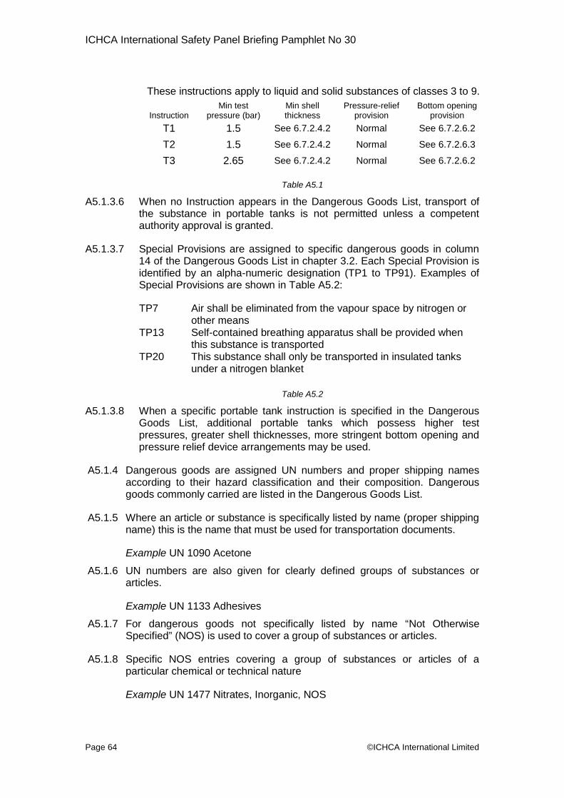
ICHCA International Safety Panel Briefing Pamphlet No 30
Page 64 ©ICHCA International Limited
These instructions apply to liquid and solid substances of classes 3 to 9.
InstructionMin test
pressure (bar)Min shellthickness
Pressure-reliefprovision
Bottom openingprovision
T1 1.5 See 6.7.2.4.2 Normal See 6.7.2.6.2
T2 1.5 See 6.7.2.4.2 Normal See 6.7.2.6.3
T3 2.65 See 6.7.2.4.2 Normal See 6.7.2.6.2
Table A5.1
A5.1.3.6 When no Instruction appears in the Dangerous Goods List, transport ofthe substance in portable tanks is not permitted unless a competentauthority approval is granted.
A5.1.3.7 Special Provisions are assigned to specific dangerous goods in column14 of the Dangerous Goods List in chapter 3.2. Each Special Provision isidentified by an alpha-numeric designation (TP1 to TP91). Examples ofSpecial Provisions are shown in Table A5.2:
TP7 Air shall be eliminated from the vapour space by nitrogen orother means
TP13 Self-contained breathing apparatus shall be provided whenthis substance is transported
TP20 This substance shall only be transported in insulated tanksunder a nitrogen blanket
Table A5.2
A5.1.3.8 When a specific portable tank instruction is specified in the DangerousGoods List, additional portable tanks which possess higher testpressures, greater shell thicknesses, more stringent bottom opening andpressure relief device arrangements may be used.
A5.1.4 Dangerous goods are assigned UN numbers and proper shipping namesaccording to their hazard classification and their composition. Dangerousgoods commonly carried are listed in the Dangerous Goods List.
A5.1.5 Where an article or substance is specifically listed by name (proper shippingname) this is the name that must be used for transportation documents.
Example UN 1090 Acetone
A5.1.6 UN numbers are also given for clearly defined groups of substances orarticles.
Example UN 1133 Adhesives
A5.1.7 For dangerous goods not specifically listed by name “Not OtherwiseSpecified” (NOS) is used to cover a group of substances or articles.
A5.1.8 Specific NOS entries covering a group of substances or articles of aparticular chemical or technical nature
Example UN 1477 Nitrates, Inorganic, NOS

ICHCA International Safety Panel Briefing Pamphlet No 30
Page 65 ©ICHCA International Limited
A5.1.9 General NOS entries covering a group of substances or articles meeting thecriteria of one or more classes or divisions. When general NOS entries aremade, the actual chemical name (the technical name) must be given inbrackets as part of the PSN
Example UN 1993 Flammable Liquid, NOS (Aluminium Martinate)
A5.1.10 A mixture or solution containing a single dangerous substance specificallylisted by name in the dangerous goods list and one or more substances notsubject to regulation is assigned the UN number and proper shipping nameof the dangerous substance.
A5.1.11 The exceptions to the above are if the solution is specifically identified byname in the Dangerous Goods List or if the entry into the Dangerous GoodsList specifically indicates that it applies to a pure substance. If the hazardclass or division or physical state or packing group of the solution or mixtureis different from that of the dangerous substance, there can be a significantchange in the measures to be taken in emergencies.
A5.1.12 For a solution or mixture where the hazard class, the physical state orpacking group is changed in comparison with the listed substance, theappropriate NOS entry shall be used including its packing and labellingprovisions
A5.2 Marine Pollutants
A5.2.1 Figure A5.1 shows the mark / placard used forEnvironmentally Hazardous Substances (AquaticEnvironment) which are known as marine pollutantsin the IMDG Code.
A5.2.2 Marine pollutants shall be transported under theappropriate entry according to their properties ifthey fall within the criteria of any of the classes 1 to8. If they do not fall within the criteria of theseclasses, they shall be transported under entry;ENVIRONMENTALLY HAZARDOUS SUBSTANCE,SOLID, N.O.S., UN 3077 or ENVIRONMENTALLY HAZARDOUSSUBSTANCE, LIQUID, N.O.S., UN 3082, as appropriate, unless there is aspecific entry for the substance in class 9.
A5.2.3 Column 4 of the Dangerous Goods List in the IMDG Code providesinformation on marine pollutants using the symbol “P”.
A5.2.4 When a substance, material or article possesses properties that meet thecriteria of a marine pollutant but is not identified in the IMDG Code, suchsubstance, material or article shall be transported as a marine pollutant inaccordance with the IMDG Code.
A5.3 Wastes
A5.3.1 Wastes, which are dangerous goods, shall be transported in accordancewith the relevant international recommendations and conventions and, inparticular, where it concerns transport by sea, with the provisions of theIMDG Code.
Figure A5.1
ICHCA International Safety Panel Briefing Pamphlet No 30
Page 66 ©ICHCA International Limited
A5.3.2 Transboundary movements under the Basel Convention
A5.3.2.1 Transboundary movement of wastes is permitted to commence only when:
notification has been sent by the competent authority of the country oforigin, or by the generator or exporter through the channel of thecompetent authority of the country of origin, to the country of finaldestination; and
the competent authority of the country of origin, having received thewritten consent of the country of final destination stating that thewastes will be safely incinerated or treated by other methods ofdisposal, has given authorization to the movement.
A5.3.2.2 In addition to the transport document required all transboundary movementsof wastes shall be accompanied by a waste movement document from thepoint at which a transboundary movement commences to the point ofdisposal. This document shall be available at all times to the competentauthorities and to all persons involved in the management of waste transportoperations.
A5.3.2.3 In the event that packages and cargo transport units containing wastes aresuffering from leakage or spillage, the competent authorities of the countriesof origin and destination shall be immediately informed and advice on theaction to be taken obtained from them.
A5.3.3 Classification of wastes
A5.3.3.1 A waste containing only one constituent which is a dangerous substancesubject to the provisions of the IMDG Code shall be regarded as being thatparticular substance. If the concentration of the constituent is such that thewaste continues to present a hazard inherent in the constituent itself, it shallbe classified according to the criteria of the applicable classes.
A5.3.3.2 A waste containing two or more constituents which are dangeroussubstances subject to the provisions of the IMDG Code shall be classifiedunder the applicable class in accordance with their dangerouscharacteristics and properties as described below.
A5.3.3.3 The classification according to the dangerous characteristics and propertiesshall be carried out as follows
determination of the physical and chemical characteristics andphysiological properties by measurement: or calculation followed byclassification according to the criteria of the applicable class(es); or
if the determination is not practicable, the waste shall be classifiedaccording to the constituent presenting the predominant hazard.
A5.3.3.4In determining the predominant hazard, the following criteria shall be takeninto account:
if one or more constituents fall within a certain class and the wastepresents a hazard inherent in these constituents, the waste shall beincluded in that class; or
if there are constituents falling under two or more classes, theclassification of the waste shall take into account the order ofprecedence applicable to dangerous substances with multiplehazards.

ICHCA International Safety Panel Briefing Pamphlet No 30
Page 67 ©ICHCA International Limited
A5.3.3.5 Wastes harmful to the marine environment only shall be transported underthe class 9 entries for ENVIRONMENTALLY HAZARDOUS SUBSTANCE,LIQUID, N.O.S., UN 3082, or ENVIRONMENTALLY HAZARDOUSSUBSTANCE, SOLID, N.O.S., UN 3077, with the addition of the word"WASTE". However, this is not applicable to substances which are coveredby individual entries in the IMDG Code.
A5.3.3.6 Wastes not otherwise subject to the provisions of the IMDG Code butcovered under the Basel Convention may be transported under the class 9entries for ENVIRONMENTALLY HAZARDOUS SUBSTANCE, LIQUID,N.O.S UN 3082 or ENVIRONMENTALLY HAZARDOUS SUBSTANCE,SOLID, N.O.S., UN 3077.

ICHCA International Safety Panel Briefing Pamphlet No 30
Page 68
Annex 6 Filling, Discharge and Manway Lid Operation
A6.1 Filling and Discharge
A6.1.1 There are three main methods of discharging tanks
by gravity where the cargo is allowed to flow out of the shell, this isgenerally the normal method for tank containers with bottom dischargeassemblies.
by the use of a pump, where the cargo is pumped out, this is generallyassociated with a top discharge valve,
by introducing a pressuring medium such as air or nitrogen into theshell generally associated with top discharge.
A6.1.2 There are two methods of filling:
by gravity, generally through the manway or top discharge valve
by pumped or pressurised flow through the manway or top or bottomdischarge valves.
A6.1.3 Each of the methods of filling or discharging will involve a means of expellingor introducing air or gas into the shell to ensure that a excessive pressure ora vacuum does not build up during the process. This can be achieved by:
filling or discharging with the manway lid open, (not used forpressurised discharge); or
filling or discharging with the manway lid closed. With the manway lidclosed and compressed or atmospheric air being passed through theairline valve
filling or discharging using a closed loop system for higher hazarddangerous goods where top discharge tanks are demanded by theregulations.)
A6.1.4 Airline valves – standard tank containers
A6.1.4.1 The main methods of loading are by gravity (“splash fill”) and by pump. Ifdischarging by air or nitrogen, a point on the top of the shell is needed toconnect up the pressurising medium supply. A small diameter valve(typically ¾ inch to 1½ inch/ 20 mm to 38 mm) is usually provided for thispurpose – the airline valve.
A6.1.4.2 During loading and dischargingoperations, depending on themethod being used, there isalways a risk of the shell becomingover pressurised and rupturing orfor partial vacuum conditions tooccur which could lead toimplosion (see Picture A6.1)Partial vacuum conditions mayalso occur in the shell duringcleaning operations if hot water or
1
Picture A6.©ICHCA International Limited

ICHCA International Safety Panel Briefing Pamphlet No 30
Page 69 ©ICHCA International Limited
steam is used and the shell not allowed to cool down to ambienttemperature before it is closed.
A6.1.4.3 The air line valve may also be used as a venting valve to allow air into thetank to prevent implosion during discharge by pump. Care has to be taken ifthis method of preventing implosion is used to ensure that the flow of airthrough the valve’s small diameter is sufficient, otherwise implosion can stilloccur.
A6.1.4.4 If discharge has taken place using a pressurising medium, the shell willremain under pressure unless steps are taken to relieve the residualpressure. Attempting to open a manway lid on a shell under pressure is anextremely dangerous practice. It may be safer to relieve the residualpressure by opening the airline valve instead, even though this is a slowerprocess.
A6.1.4.5 Pressure gauges may be fitted to airline valves and vapour return lines ontop discharge tanks. These gauges should not be confused with the tell talegauges fitted in the void between an in series bursting disc and press reliefvalve.
A6.1.5 Vapour Return
A6.1.5.1 Some dangerous goods are so dangerous that either to have the tank openfor filling or discharge or, for example, to vent any excess pressure in theshell from the pressurising medium to atmosphere, may be extremelydangerous as the escaping vapour may be a mixture of highly toxic orcorrosive vapours and the pressurising medium. Nevertheless, the excesspressure or creation of partial vacuum conditions when loading andunloading these substances must be controlled. The solution is a closed(vapour recovery) system with more than one valve fitted which allowsgreater flexibility in load and discharge arrangements
A6.1.5.2 In the same area as the valve over the siphon pipe there will usually be atleast two other valves – see the two valves to the right in Picture 24. Theymay have the same diameter or one may be larger than the other. Onevalve will be intended to be used either for filling with a pipe or hosetemporarily bolted onto the flange once the covering plate has beenremoved or as a vapour return line. The second valve is intended to be usedeither as connection for pressure discharge or it, too, may be used as avapour return line.
A6.1.5.3 Particularly when discharging is taking place, the tank container is in need ofvapour to replace the displaced liquid or implosion may occur. On the otherhand, the receiving storage tank suffers a pressure increase as the liquidlevel rises with consequent risk of bursting. The situation is balanced usingthe vapour return line to divert the unwanted vapour from the storage tankinto the tank container.
A6.1.5.4 When loading or discharging top discharge tanks using close circuitsystems, consideration should always be given to fitting non-return valves atsuitable points in the lines. These are not normally provided on the tankcontainers themselves.

ICHCA International Safety Panel Briefing Pamphlet No 30
Page 70 ©I
A6.2 Manway Lid Operating
A6.2.1 Design
A6,2,1,1 The number of swing bolts will varyaccording to the pressure rating of theshell. When loosened, they fold back ontheir hinge to allow the manway lid to beopened.
A6.2.1.2 Picture A6.2 shows an example of swingbolts which are tightened using nuts. Theshanks and wing nut of the bolts may bemade of the same metal such as stainlesssteel (see Picture A6.3) while otherdesigns may have a wing nut made of asofter non-ferrous metal (see Picture A6.4).
A6.2.1.3 Compatible sealing material must be fittedinto a circular recess made in the manwaylid (see Picture A6.5) or in the neck ring toreceive the seal.
A6.2.1.4 It is important that the manway lid sealingmaterial is appropriate to the cargo carried,in good condition and complete. Anincompatible, incomplete, poorly fitted ordamaged seal (gasket) will present asevere risk of the cargo, or its vapoursescaping.
A6.2.2 Opening the Manway Lid:
A6.2.2.1 Great care must be taken by whoever is opening matank container is under pressure. Pressure may, for ea tank after discharge because it has not been fullemptying. Pressure may also be present due to volatila so-called “nitrogen blanket” has been used to inert thtanks) or gas phase (gas tanks). This warning appliintended for both dangerous goods and non-regulatedtanks – see 9.3.4
Caution: All pressure must be released fromopening the manway lid
Picture A6.2
C
xy
e
Picture A6.5
Picture A6.3
Picture A6 4HCA International Limited
nway lids in case theample, remain insidedepressurised after
e vapours or becausee ullage space (liquids to tank containers
goods, including beer
the tank prior to

ICHCA International Safety Panel Briefing Pamphlet No 30
Page 71 ©IC
A6.2.2.2 The following steps should be taken when opening manway lids:
Loosen the hand nuts on the swingbolts by rotating the hand nuts anti-clockwise, keeping the swing boltsupright and located in their receivingbracket. Start with the hand nutscloset to the hinge and proceed inthe order shown in Picture A6 5.
Do not swing the swing boltsaway from their receivingbracket.
Wait for full evacuation of anyresidual pressure that might have remained into t
Pull the manway lid handle firmly upwards ingasket and then let it back.
Complete the unscrewing of the swing bolts, thfrom their receiving bracket in the same orderA6.5
Open the manway lid by rotating it around(hinge).
A6.2.3 Closing the Manway Lids
A6.2.3.1 The following steps should be taken when closing man
Check the gasket and gasket receiving surfacremove any dirt or grit.
Position the coverlid gasket in front of the neck ri
Close the manway lid
Swing the swing bolts to the uprightposition and position them in theirreceiving bracket
Rotate the hand nuts clockwise inorder to tighten the swing bolts.Tighten in the order shown in PictureA6.6
Lock-tighten the swing bolts with atorque of 3 m daN in order to ensuregasket tightness
Note 1: It is recommended that a torque wrench be ucorrect torque is applied
Note 2: Although a torque of 3 m daN should beproper leak tightness, it is acceptable to appldaN if required with no risk of damaging thelid and receiving brackets.
3
1
7
6
2
4
5
8
5
8
4
Picture A6.
he tank.
order to release the
en swing them awayas shown in Picture
its horizontal spindle
way lids:
e for cleanliness and
ng sealing surface
s
y
2
6
7
5
3
1
Picture A6.6
HCA International Limited
ed to ensure that the
necessary to ensurea torque up to 10 m
swing bolts, manway

ICHCA International Safety Panel Briefing Pamphlet No 30
Page 72 ©ICHCA International Limited
A6.2.4 In Service
It is possible that the seal will be compacted during transport; this could becaused by vibration or the properties of the seal material. Should thishappen then there is a risk that the seal will be broken thus increasing therisk of the cargo or its vapours escaping. If this should happen then theswing bolts should be re-tightened.
A6.2.5 Maintenance
A6.2.5.1 Once per year the manway lid mechanism and dimensions should bechecked as follow:
Manway lid and neck ring thicknesses
The actual thickness shall remain over the minimum calculationthickness after potential corrosion. The values shown below aretypical:
Minimum manway lid thickness: 4.4 mm (5 mm at time of delivery)
Minimum neckring thickness: 7.5 mm (8 mm at time of delivery)
Welding visual check
No crack should show on swing bolts bracket attachments, fillets andon the circular weld between collar and neckring
Seal tightness check
Replace gasket if necessary
Swing bolt threads check
Replace the swing bolts if the threads are scratched or elongated
Pressure test inspection
According to tank standards requirements
A6.3 Safety
A6.3.1 All valves, ports and access lids must be properly closed once filling hasbeen completed.
A6.3.2 Manway lids are a major cause of leaks due to improper fitting of the seal,incorrectly tightening swing bolts or swing bolts that have loosened duringtransport. The structure of a tank container can survive a drop from height,but if it lands upside down and the manway lid is not tightened correctlythere will be a serious risk of the cargo escaping.
A6.3.3 If there is any doubt about the integrity of any closure then the shippershould be informed immediately.


