Safe & Sound - Bridge and Structural Bearing Systems
5
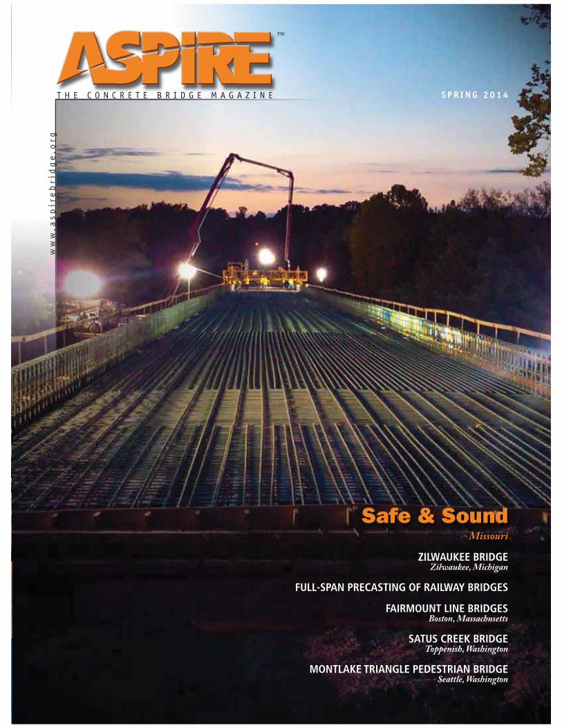
THE CONCRETE BRIDGE MAGAZINE www.aspirebridge.org SPRING 2014 ZILWAUKEE BRIDGE Zilwaukee, Michigan FULL-SPAN PRECASTING OF RAILWAY BRIDGES FAIRMOUNT LINE BRIDGES Boston, Massachusetts SATUS CREEK BRIDGE Toppenish, Washington MONTLAKE TRIANGLE PEDESTRIAN BRIDGE Seattle, Washington Safe & Sound Missouri
Transcript of Safe & Sound - Bridge and Structural Bearing Systems
T H E C O N C R E T E B R I D G E M A G A Z I N E
ww
w.a
sp
ire
bri
dg
e.o
rg
S P R I N G 2 0 1 4
ZILWAUKEE BRIDGE Zilwaukee, Michigan
FULL-SPAN PRECASTING OF RAILWAY BRIDGES
FAIRMOUNT LINE BRIDGESBoston, Massachusetts
SATUS CREEK BRIDGEToppenish, Washington
MONTLAKE TRIANGLE PEDESTRIAN BRIDGESeattle, Washington
Safe & Sound Missouri

CABA. . . . . . . . . . . . . . . . . . . . . . . . . . . . . . 23
Creative Design Resolutions . . . . . . . . . . . . 3
D.S. Brown . . . . . . . . . . . . Inside Back Cover
DSI/Dywidag Systems Intl. . . . . . . . . . . . . 27
FIGG . . . . . . . . . . . . . . . . . Inside Front Cover
Fyfe . . . . . . . . . . . . . . . . . . . . . . . . . . . . . . . 37
Helser Industries . . . . . . . . . . . . . . . . . . . . . 5
Hilman Rollers . . . . . . . . . . . . . . . . . . . . . . 34
LARSA . . . . . . . . . . . . . . . . . . . . . . . . . . . . . 47
MMFX . . . . . . . . . . . . . . . . . . . . . . . . . . . . . 42
Parsons Brinkerhoff . . . . . . . . . . . Back Cover
PCI . . . . . . . . . . . . . . . . . . . . . . . . 5, 19, 41, 43
PERI . . . . . . . . . . . . . . . . . . . . . . . . . . . . . . . 45
Pile Dynamics . . . . . . . . . . . . . . . . . . . . . . . 25
Safway . . . . . . . . . . . . . . . . . . . . . . . . . . . . 15
Williams Form Engineering Corp. . . . . . . . 42
Advertisers Index
ASPIRE, Spring 2014 | 1
CON T EN T S
Photo: The Louis Berger Group Inc.
Phot
o: K
iew
it.
Photo: Michigan Department of Transportation.
Photo: Washington State Department of Transportation Visual Engineering Resource Group.
FeaturesTaking the Lead 6 Kiewit adapts to new delivery methods, new technologies, and changing requirements to build bridges ranging from the simple to the complex.
Zilwaukee Bridge 12 Bearing replacement need determined after 18 years of service.
Full-Span Precasting of Railway Bridges 16
Fairmount Line Bridges 20 Rehabilitating Boston’s commuter rail line.
Satus Creek Bridge 24 Curved, tilted, precast concrete box girders key to replace-ment project.
Montlake Triangle Pedestrian Bridge 28 Curved, post-tensioned structure links Seattle campus to downtown.
DepartmentsEditorial 2
Concrete Calendar 4
Perspective 10
Aesthetics Commentary 31
Accelerated Bridge Construction 33
FHWA—The Long-Term Bridge Performance Program 36
State—Hawaii 38
CCC—Rain Rocks Rock Shed 40
Authority—Illinois Tollway 44
Concrete Connections 46
AASHTO LRFD—2014 Interim Changes Related to Concrete Structures 48
12
24
20

Opened to traff ic in 1989, the 325-ft- long approach spans and 393-ft-long river span of the Zilwaukee Bridge rise to 125 ft above the Saginaw River to accommodate marine shipping traffic. The bridge is a 1.5-mile-long twin concrete segmental structure comprised of 1592 precast concrete segments, each weighing an average of 160 tons. It was the largest precast concrete segmental project in the United States at the time. The 25-span northbound structure and 26-span southbound structure carry I-75 traffic over the Saginaw River through the city of Zilwaukee, Mich.
The Zilwaukee Bridge was designed to the 1973-77 AASHTO Standard Specifications, with HS-25 live loading and AASHTO Zone 1 seismic loads. The single-cell segments of the superstructure box girder are approximately 73 ft wide at the top flange, 36 ft wide at the bottom flange, and vary in depth from 8 ft at midspan to 20 ft at the piers. Each structure contains eight, in-span, quarter-point hinges to accommodate expansion and rotation from thermal gradients.
Bearing ProblemsOriginally, the superstructure rested
on high-capacity pot bearings at the piers and expansion joint locations. The pier bearings were mostly fixed with one of the two pier bearings allowing transverse movement. The e lastomer pot bear ings a l lowed for 0.04 radians of rotation and accommodated 12 in. of longitudinal and/or transverse movement via the polytetrafluoroethylene (PTFE) sliding surface.
Bearing problems were identified during the first detailed inspection in 1993. Neoprene elastomer was leaking from the sealing ring around the pot piston at the expansion hinge and pier bearing locations. This reduced the rotational capacity of the bearing. There were also indications of wearing in the PTFE sliding surfaces, which was jeopardizing thermal movements of the bridge. At some pier locations, the loss of elastomer resulted in contact between the top sole plate and the bottom masonry plate edge. In 2007, the Michigan Department of Transportation (MDOT) began discussions to replace the 104 pier bearings and 34 expansion joint bearings and upgrade the bearings to current AASHTO service criteria.
Bearing ReplacementThe challenges associated with the bearing replacement were clear. Loads approaching 17 million pounds would
profile ZILWAUKEE BRIDGE / ZILWAUKEE, MICHIGAN BRIDGE REPLACEMENT CONSULTANT: T.Y. Lin International, San Francisco, Calif.
QUALITY ASSURANCE ENGINEER: Janssen and Spaans Engineer Inc., Chicago, Ill.
CONSTRUCTION ENGINEER: Corven Engineering Inc., Tallahassee, Fla.
PRIME CONTRACTOR: PCL Construction, Tampa, Fla.
POST-TENSIONING CONTRACTORS: PCL Construction, Tampa, Fla., and Walter Toebe Construction, Wixom, Mich.
The Zilwaukee Bridge, a 1.5-mile-long twin concrete segmental structure, carries I-75 traffic over the Saginaw River. All Photos: Michigan Department of Transportation.
by Corey E. Rogers, Michigan Department of Transportation
Bearing replacement need determined after 18 years of serviceZILWAUKEE BRIDGE
12 | ASPIRE, Spring 2014
PROJECT
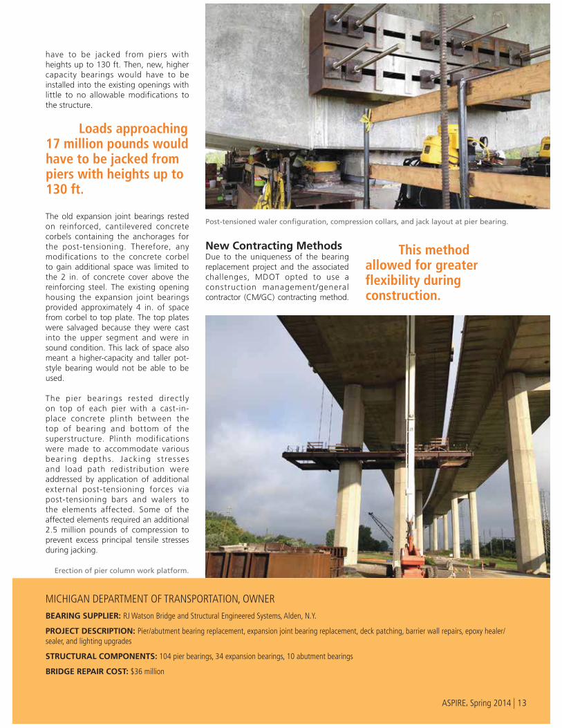
have to be jacked from piers with heights up to 130 ft. Then, new, higher capacity bearings would have to be installed into the existing openings with little to no allowable modifications to the structure.
The old expansion joint bearings rested on reinforced, cantilevered concrete corbels containing the anchorages for the post-tensioning. Therefore, any modifications to the concrete corbel to gain additional space was limited to the 2 in. of concrete cover above the reinforcing steel. The existing opening housing the expansion joint bearings provided approximately 4 in. of space from corbel to top plate. The top plates were salvaged because they were cast into the upper segment and were in sound condition. This lack of space also meant a higher-capacity and taller pot-style bearing would not be able to be used.
The pier bearings rested directly on top of each pier with a cast-in-place concrete plinth between the top of bearing and bottom of the superstructure. Plinth modifications were made to accommodate various bearing depths. Jacking stresses and load path redistribution were addressed by application of additional external post-tensioning forces via post-tensioning bars and walers to the elements affected. Some of the affected elements required an additional 2.5 million pounds of compression to prevent excess principal tensile stresses during jacking.
New Contracting Methods Due to the uniqueness of the bearing replacement project and the associated challenges, MDOT opted to use a construction management/general contractor (CM/GC) contracting method.
MICHIGAN DEPARTMENT OF TRANSPORTATION, OWNER
BEARING SUPPLIER: RJ Watson Bridge and Structural Engineered Systems, Alden, N.Y.
PROJECT DESCRIPTION: Pier/abutment bearing replacement, expansion joint bearing replacement, deck patching, barrier wall repairs, epoxy healer/sealer, and lighting upgrades
STRUCTURAL COMPONENTS: 104 pier bearings, 34 expansion bearings, 10 abutment bearings
BRIDGE REPAIR COST: $36 million
Erection of pier column work platform.
Loads approaching 17 million pounds would have to be jacked from piers with heights up to 130 ft.
Post-tensioned waler configuration, compression collars, and jack layout at pier bearing.
This method allowed for greater flexibility during construction.
ASPIRE, Spring 2014 | 13
This method allowed for greater flexibility during construction of such a complicated project. An example of this flexibility occurred during the construction management phase and involved the jacking scheme for the pier bearings.
Ear ly designs cal led for shoring towers that would support the jacked superstructure from the footings. The contractor proposed placing the jacks on top of the pier columns and horizontally compressing the tops of the columns with pier collars to confine them and prevent column edge spalling at jack bearing locations. This method was determined to be feasible and eliminated the need for costly shoring towers.
It was also during the construction management phase that MDOT decided to use disk bearings instead of pot bearings. The disk bearing is simpler in design and thinner than a pot bearing, but requires a larger footprint. A polyurethane disk provides the required rotational capacity and a stainless steel top plate coated in PTFE provides the lateral movements. The disk bearings were able to fit into the 4-in.-deep opening at the expansion joints and provide the needed bearing capacity at pier bearing locations. Upon completion of the design phase, a guaranteed maximum price was negotiated, with the final cost of the project totaling
$36 million, and the contract moved into the second, or general contractor, phase.
ChecksConstruction began in April 2013 with the closure of the southbound structure. MDOT required the contractor to demonstrate a complete pier and expansion bearing replacement prior to commencing production mode. This allowed MDOT inspectors and construction engineers to become comfortable with the entire replacement operation and work through any design/constructability issues before work began at multiple bearing locations.
The contractor submitted a detailed jacking procedure for MDOT approval. MDOT also created specialized jacking forms for inspection staff to use during all jacking operations. Any deviations from the procedures or forms resulted in an immediate stoppage of work and reevaluation of the procedure.
Ground penetrating radar was used at all proposed coring locations. Chipping was allowed to visually verify the tendon locations. Coring was conducted in the web walls for diaphragm strengthening and in the deck for strongback installation and platform erection.
Platforms weighing approximately 90 tons were designed and constructed by the contractor and hoisted into place at the top of the piers with hydraulic jacks and high tensile rods. Twelve 1¾-in.-diameter post-tensioning rods were installed transversely through the box at most of the pier diaphragm locations and stressed to 210 kips each to support the 12 ft by 25 in. load redistribution walers. The smaller diaphragm locations received modifications by placing reinforced, post-tensioned concrete blocks adjacent to the diaphragm and over the jacking points. The larger diaphragms received no strengthening modifications.
Two 2½-in.-diameter post-tensioning rods held the compression collars and were stressed to 540 kips each. Up to eight 600-ton hydraulic jacks per bearing were used to lift the superstructure from the bearings. Steel rods were anchored into the pier and bottom of the superstructure,
and surveys were used to monitor displacement. The existing bearings and concrete plinth were then removed with the use of a wire saw, the new steel reinforcement was anchored with epoxy into the top of the pier and bottom of the superstructure, and the new disk bearings were set into place. Pressure grouting of bearing pedestals with a non-shrink cementitious grout was conducted and allowed to reach a compressive strength of 5 ksi prior to lowering the structure.
The expansion joint bearings were replaced with the use of a strongback system. Overhead and underslung beams spanning the width of the box were supported by twelve 2½-in.-diameter post-tensioning rods stressed to 460 kips each. Four 400-ton hydraulic jacks were used to lift the supported span. The old bearings were then removed and the new disk bearings installed and grouted into place.
Due to the excessive movements associated with the thermal gradient, MDOT decided all jacking and lowering operations be conducted between 7 and 9 a.m., when the structure has the least thermal movement. This provided consistency in the jacking displacements and ensured no new stresses were being introduced into the bridge upon release of the jacks.
Concluding RemarksThe bearing replacement on the southbound structure was successfully completed ahead of schedule in November 2013 . Much o f the success can be attributed to the group of contractors, subcontractors, consultants, designers, and MDOT staff that continually found solutions when confronted with challenges, and who had a great sense of ownership and pride regarding the project. There was no template for a project like this and many of the procedures were drafted as needed. MDOT was able to gain valuable experience on a complex bridge, built by a previous generation.
____________ Corey E. Rogers is the bridge construction engineer with the Michigan Department of Transportation in Lansing, Mich.
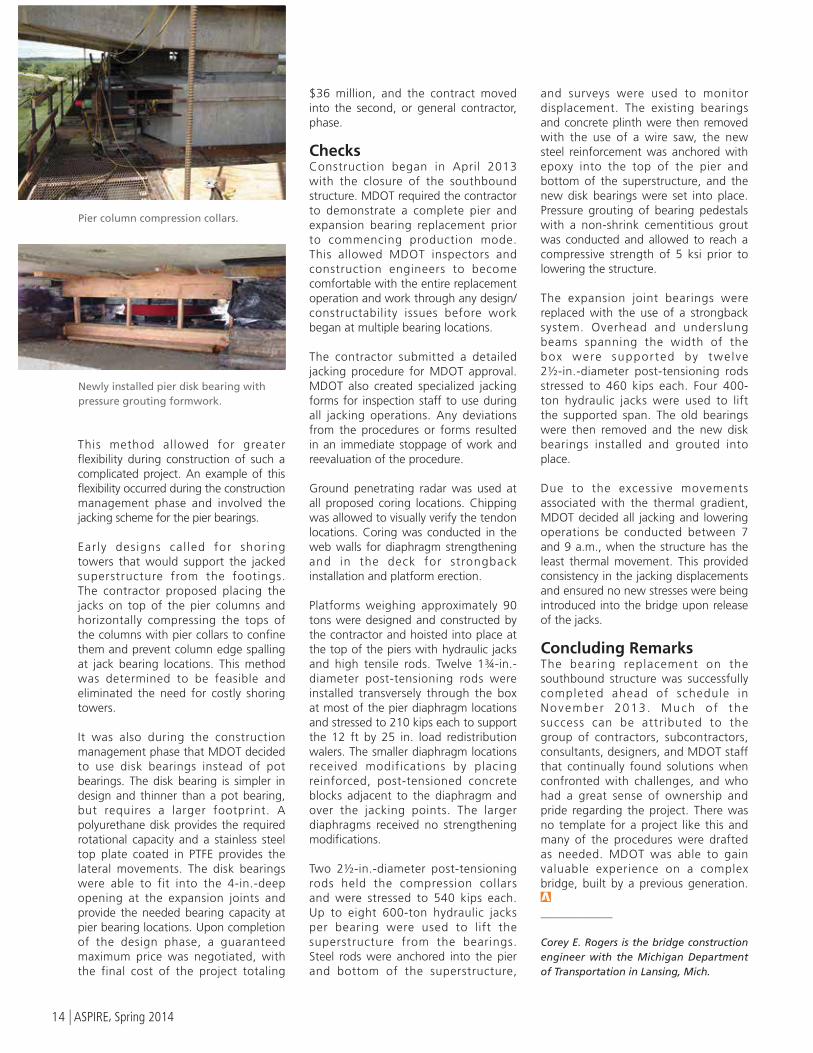
Pier column compression collars.
Newly installed pier disk bearing with pressure grouting formwork.
14 | ASPIRE, Spring 2014