Sacramento City College Engineering Design Technology...
172
Sectional Views and Conventions 1 Sectional Views and Conventions Sacramento City College Engineering Design Technology
Transcript of Sacramento City College Engineering Design Technology...

Sectional Views and Conventions 1
Sectional Views and Conventions
Sacramento City College
Engineering Design Technology

2 Sectional Views and Conventions
Objectives
Describe the purpose of a sectional view.
Select the appropriate type of sectional view to show the hidden feature.

3 Sectional Views and Conventions
Objectives
Show ribs, webs, and fasteners when the cutting plane passes through them.
Rotate certain features into the cutting plane.
Describe and use conventional breaks and symbols

4 Sectional Views and Conventions
Vocabulary
Auxiliary section
Broken-out section
Conventional break
Crosshatching
Cutting plane
Cutting-plane line
Full section
Half section
Offset section
Phantom section
Removed Section
Revolved Section
Ribs
Section lining
Webs

Sectional Views and Conventions 5
Sectional Views

6 Sectional Views and Conventions
Sectional Views
Technical drawings must show all parts of an object, including Insides and
Other parts not easily seen.
Hidden lines could be used to show hidden features.

7 Sectional Views and Conventions
Sectional Views
If hidden lines are used, the part must be simple.
If the shape is complicated, dashed lines may show it poorly.

8 Sectional Views and Conventions
Sectional Views
Instead of hidden lines a special view called a section or sectional view should be drawn instead.
A sectional view shows an object as if part of it were cut away to expose the insides.

9 Sectional Views and Conventions
Drawing Sectional Views
To draw a sectional view, imagine that a wide-blade knife has cut through the object.
Call this knife a cutting plane.

10 Sectional Views and Conventions
Cutting-Plane “Knife”

11 Sectional Views and Conventions
The Cutting-Plane Line
The cutting-plane line represents the cutting plane as viewed from an edge. Refer to Figure 9-9, 9-10

12 Sectional Views and Conventions
Drawing Sectional Views
Remove everything in front of the plane.
The cut surface and interior parts can be seen.

13 Sectional Views and Conventions
Drawing Sectional Views
On a normal view, show where the cutting plane passes through the object by drawing a special line called a cutting-plane line.

14 Sectional Views and Conventions
Section Views/Cutting Plane Lines
Cutting Plane lines have two forms: A thick hidden (evenly spaced dashed)
line.
A phantom line in accordance with ASME Y14.2M.
A A
A A

15 Sectional Views and Conventions
Section Views/Cutting Plane Lines
The arrows on the cutting-plane line indicate the direction of sight when looking at the section view.
A A

16 Sectional Views and Conventions
Section Line

17 Sectional Views and Conventions
Section Views/Cutting Plane Lines
The cutting-plane lines are labeled with letters that relate to the proper section view.
The section name, SECTION A-A, is placed under the view.

18 Sectional Views and Conventions
Normal Views
Top View
Front View Right Side View Isometric Pictorial View

19 Sectional Views and Conventions
Cutting-Plane
Section View

20 Sectional Views and Conventions
Section Views/Cutting Plane Lines
The arrows on the cutting-plane line indicate the line of sight when looking at the section view.
Section A-A

21 Sectional Views and Conventions
Section Views/Cutting Plane Lines
The cutting-plane lines are labeled with letters that relate to the proper section view.
SECTION A-A, is placed under the view.
Section A-A
A A

22 Sectional Views and Conventions
Section Views/Cutting Plane Lines
When more than one section view is drawn, labels continue with B-B through Z-Z.

Sectional Views and Conventions 23
Section Lines and Material Types

24 Sectional Views and Conventions
Drawing Sectional Views
On the sectional view, show the cut surface by marking it with evenly spaced thin lines.
This is called section lining or cross-hatching.

25 Sectional Views and Conventions
Section Line Rules
Section lines may be drawn using different patterns to represent the specific type of material.

26 Sectional Views and Conventions
Cross-Hatching
The American National Standards Institute (ANSI) provides many standard symbols to indicate different types of materials.
Refer to Figure 9-2.

27 Sectional Views and Conventions
Cross-Hatching/Section Lines

28 Sectional Views and Conventions
Cross-Hatching/Section Lines

29 Sectional Views and Conventions
Cross-Hatching/Section Lines

30 Sectional Views and Conventions
Cross-Hatching/Section Lines

31 Sectional Views and Conventions
Cross-Hatching/Section Lines

32 Sectional Views and Conventions
Cross-Hatching/Section Lines

33 Sectional Views and Conventions
Cross-Hatching/Section Lines

34 Sectional Views and Conventions
Cross-Hatching
Cross-hatching lines usually are spaced about 0.03 inches to 0.12 inches. (Think 1/8”).
Space lines by eye, not by measuring Refer to Figures 9-3, 9-4.

35 Sectional Views and Conventions
Cross-Hatching
Evenly space cross-hatching lines, usually at a 45o angle.
Graying or shading may also be used Refer to Figures 9-6, 9-7

36 Sectional Views and Conventions
Edge Shading

Sectional Views and Conventions 37
Section Lining Rules

38 Sectional Views and Conventions
Section Line Rules
1. Section lines are placed at 45o unless another angle is required to satisfy the next two rules.
Avoid section lines placed at angles greater than 75o or less than 15o degrees from horizontal.

39 Sectional Views and Conventions
Section Line Rules
2. Section lines should not be drawn parallel or perpendicular to any other adjacent lines on the drawing.
Section lines are NEVER drawn parallel to or at right angles to visible lines. Refer to Figure 9-8

40 Sectional Views and Conventions
Figure 9-8
Section Lines/Object Lines

41 Sectional Views and Conventions
Section Lines/Object Lines
Figure 9-8

42 Sectional Views and Conventions
Section Line Rules
3. Section lines should not cross object lines.

43 Sectional Views and Conventions
Centerline as Cutting Plane Line
A cutting plane line is not needed when it is clear that the section is taken along an object’s main centerline.
Refer to Figure 9-11.

44 Sectional Views and Conventions
Figure 9-11

45 Sectional Views and Conventions
Sections Through Assemblies
If the drawing shows more than one piece in section, draw the section lines at different angles.
Refer to Figures 9-12, 9-13.

46 Sectional Views and Conventions

47 Sectional Views and Conventions

Sectional Views and Conventions 48
Outline Sectioning and Graying

49 Sectional Views and Conventions
Outline Sectioning
When the area is large, you can use outline sectioning. Refer to Figure 9-5

50 Sectional Views and Conventions
Outline Sectioning

51 Sectional Views and Conventions
Outline Sectioning

52 Sectional Views and Conventions
Graying

Sectional Views and Conventions 53
Types of Sectional Views

54 Sectional Views and Conventions
Types of Sectional Views
Types of Sections: Full Sections.
Offset Sections.
Half Sections.
Broken-Out Sections.
Revolved Sections.
Removed Sections.
Auxiliary Sections.
Phantom (Hidden) Sections.

Sectional Views and Conventions 55
Full Sections

56 Sectional Views and Conventions
Full Sections
A full section is a sectional view that shows an object as if it were cut completely apart from one end or side to the other. Refer to Figure 9-16
These views are sometimes just called sections.

57 Sectional Views and Conventions
Front View

58 Sectional Views and Conventions
Full Section

59 Sectional Views and Conventions
Full Sections
The two most common types of full sections are vertical and
profile sections.
Refer to Figures 9-17 and 9-18.

60 Sectional Views and Conventions

61 Sectional Views and Conventions

62 Sectional Views and Conventions
Section Views/Cutting Plane Lines

63 Sectional Views and Conventions
Full Sections
Full sections remove half the object.
In a full section, the cutting-plane line passes completely through the object along a center plane.

64 Sectional Views and Conventions

65 Sectional Views and Conventions

66 Sectional Views and Conventions
Full Sectioning
Sectioning is also used in other drafting fields, such as architectural and structural drafting.
Cross sections through buildings show the construction methods and materials.

67 Sectional Views and Conventions

68 Sectional Views and Conventions

Sectional Views and Conventions 69
Offset Sections

70 Sectional Views and Conventions
Offset Sections
In full sections, the cutting plane is usually taken straight through the object.
Offset sections are almost the same as full sections, Difference: the cutting-plane line is
staggered.
The line cuts through features that are not in a straight line.

71 Sectional Views and Conventions
Offset Sections
The cutting plane can also be offset or shifted at one or more places to show a detail or to miss a part. Refer to Figure 9-19.
The cutting plane is offset to pass through the two bolt holes.

72 Sectional Views and Conventions
Offset Section - Figure 9-19

73 Sectional Views and Conventions

Sectional Views and Conventions 74
Half Sections

75 Sectional Views and Conventions
Half Sections
A half section is one half of a full section.
A full section makes an object look as if half if it has been cut away. Refer to Figure 9-20.
A half section looks as if one quarter of the original object has been cut away.

76 Sectional Views and Conventions
Half Sections
The term half section is used because Half of the view appears in section.
The other half is shown as an exterior view.

77 Sectional Views and Conventions
Half Section - Figure 9-20

78 Sectional Views and Conventions
Half Sections
The half section shows one half of the front view in section. Refer to 9-20 E.

79 Sectional Views and Conventions
Half Sections
Half sections are commonly used on symmetrical objects.
Both the inside and outside can be shown in one view.

80 Sectional Views and Conventions
Half Sections
A centerline is used to separate the sectioned part of the view from the un-sectioned part.
Hidden lines are normally omitted from the un-sectioned side.

81 Sectional Views and Conventions
Half Sections - Figure 9-20
Use a centerline where the exterior and half-sectional views meet since the object is not actually cut.

82 Sectional Views and Conventions
Half Sections
In the top view, show the complete object, since no part is actually removed.
Use one arrow for the direction of viewing.

83 Sectional Views and Conventions
Half Sections - Figure 9-20

84 Sectional Views and Conventions
Half Sections
Half sections show one-quarter of the object removed.
The term half section is used because Half of the view appears in section.
The other half is shown as an exterior view.

Sectional Views and Conventions 85
Broken Sections

86 Sectional Views and Conventions
Broken Sections
A broken-out section shows an object as it would look if a portion of it were cut partly away from the rest by a cutting-plane and then “broken off” to reveal the cut surface and insides. Refer to Figure 9-21

87 Sectional Views and Conventions
Broken Sections - Figure 9-21

88 Sectional Views and Conventions
Broken Sections - Figure 9-21

89 Sectional Views and Conventions
Broken Sections - Figure 9-21

90 Sectional Views and Conventions
Broken Sections
A broken-out section show some inside detail without drawing a full or half-section.

91 Sectional Views and Conventions
Broken Sections
The broken-out section is bounded by a short-break line drawn freehand the same thickness as visible lines. Refer to Figure 9-22

92 Sectional Views and Conventions
Broken-out Sections
Broken-out sections show only a small portion of the object removed.
Broken-out sections clarify hidden features.

93 Sectional Views and Conventions
Broken-out Sections

94 Sectional Views and Conventions
Broken-out Sections

95 Sectional Views and Conventions
Broken-out Sections

96 Sectional Views and Conventions
Broken-out Sections

Sectional Views and Conventions 97
Aligned Sections

98 Sectional Views and Conventions
Aligned Sections
Aligned sections are used when a feature is out of alignment with the center plane.
An offset section would distort the image.

99 Sectional Views and Conventions
Aligned Sections
The cutting-plane line cuts through the feature to be sectioned.
The feature is then rotated to align with the center plane before projecting into the section view.

100 Sectional Views and Conventions

Sectional Views and Conventions 101
Revolved Sections

102 Sectional Views and Conventions
Revolved Sections
Revolved sections clarify the contour of objects that have the same shape throughout their length.
The section is revolved in place within the object, or part of the view may be broken away.

103 Sectional Views and Conventions
Revolved Sections
A revolved section has a cutting plane passing through a part, and then revolved 90o so that its shape can be seen clearly.

104 Sectional Views and Conventions
Revolved Sections
Use a revolved section: When the part is long and thin.
When its shape in cross section is the same throughout.
Refer to Figure 9-25

105 Sectional Views and Conventions
Revolved Section - Figure 9-23

106 Sectional Views and Conventions
Revolved Section - Figure 9-24

107 Sectional Views and Conventions
Revolved Section - Figure 9-24

108 Sectional Views and Conventions
Revolved Sections
The view may be shortened.
Give the full-length of the part by a dimension.
This lets you draw a large part with a revolved section in a short space.

109 Sectional Views and Conventions
Revolved Sections Figure 9-24

110 Sectional Views and Conventions
Revolved Sections Figure 9-24

111 Sectional Views and Conventions

Sectional Views and Conventions 112
Removed Sections

113 Sectional Views and Conventions
Removed Sections
Removed sections serve much the same function as revolved sections.
The section view is removed from the regular view.

114 Sectional Views and Conventions
Removed Sections
A removed section is taken from its normal place on the view and moved somewhere else on the drawing sheet.
A cutting-plane line shows where the section was taken.

115 Sectional Views and Conventions
Removed Sections
The removed section must be positioned to look as if it were in its normal place on the view.
The removed section cannot be rotated in just any direction !
Refer to Figure 9-26 for examples

116 Sectional Views and Conventions
Removed Sections
When multiple removed sections are taken, the cutting planes and related views are labeled.
Drawing only the ends of the cutting-plane lines simplifies the views.

117 Sectional Views and Conventions

118 Sectional Views and Conventions

119 Sectional Views and Conventions
Removed Sections Figure 9-26

120 Sectional Views and Conventions
Removed Sections Figure 9-26

121 Sectional Views and Conventions
Removed Sections Figure 9-26

122 Sectional Views and Conventions
Removed Sections
Use bold letters to identify a removed section and its corresponding cutting plane.

123 Sectional Views and Conventions
Removed Section
A removed section can be a sliced section or it can show additional detail visible beyond the cutting lane.

124 Sectional Views and Conventions
Removed Sections
When multiple removed sections are taken, the cutting planes and related views are labeled.
Drawing only the ends of the cutting-plane lines simplifies the views.

Sectional Views and Conventions 125
Special Cases

126 Sectional Views and Conventions
Special Cases
Certain exceptions are made to the general sectioning rules for: Ribs and Webs in Section.
Hidden and Visible Lines.
Alternate Section Lining.
Certain Parts usually not sectioned.
Rotated Features in Section.

Sectional Views and Conventions 127
Special Cases - Ribs in Section

128 Sectional Views and Conventions
Ribs and Webs in Section
Show ribs as if the cutting plane passed in front of the rib. Refer to Figure 9-29.

129 Sectional Views and Conventions
Ribs and Webs in Section

130 Sectional Views and Conventions
Ribs and Webs in Section
If a cutting plane passes through a rib, a web or other thin, flat part, at right angles to the flat side,
Show the section lines for that part.
Refer to Figure 9-30.
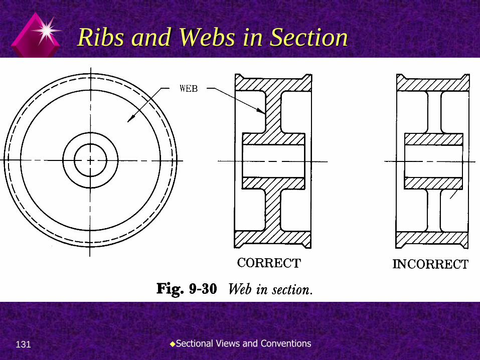
131 Sectional Views and Conventions
Ribs and Webs in Section

Sectional Views and Conventions 132
Sections
and
Hidden and Visible Lines

133 Sectional Views and Conventions
Hidden and Visible Lines
Do not draw hidden lines on sectional views unless they are needed for dimensioning or for clearly describing the shape. Refer to Figure 9-31A
A hub is described clearly using no hidden lines.

134 Sectional Views and Conventions
Hidden and Visible Lines

135 Sectional Views and Conventions
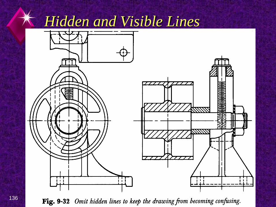
Hidden and Visible Lines
On sectional assembly drawing hidden lines are generally omitted. Refer to Figure 9-32.
Include all lines that would be visible on or beyond the plane of the section.
136 Sectional Views and Conventions
Hidden and Visible Lines

137 Sectional Views and Conventions
Hidden and Visible Lines
In a section view, include all lines that would be visible on or beyond the plane of the section.
Refer to Figure 9-33 and 9-34.

138 Sectional Views and Conventions
Hidden/Visible Lines Fig 9-33

139 Sectional Views and Conventions
Hidden/Visible Lines Fig 9-33

140 Sectional Views and Conventions
Hidden/Visible Lines Fig 9-33

141 Sectional Views and Conventions
Hidden/Visible Lines Fig 9-34

142 Sectional Views and Conventions
Hidden/Visible Lines Fig 9-34

Sectional Views and Conventions 143
Alternate Section Lining

144 Sectional Views and Conventions
Alternate Section Lining
Alternate section lining is a pattern made by leaving out every other section line. Refer to Figure 9-35A & B.
Alternate section lines are useful to show ribs and other thin, flat pieces in one-view drawings.

145 Sectional Views and Conventions

Sectional Views and Conventions 146
Other Parts NOT Sectioned

147 Sectional Views and Conventions
Other Parts NOT Sectioned
Do not draw section lines on spokes and gear teeth when the cutting plane passes through them.
Refer to Figure 9-36.

148 Sectional Views and Conventions

149 Sectional Views and Conventions
Other Parts Not Sectioned
Do not draw section lines on these objects when the cutting plane passes lengthwise through the object. Spokes
Gears teeth
Shafts
Bolts
Pins
Rivets
Draw section lines when cut across the axis

150 Sectional Views and Conventions

151 Sectional Views and Conventions

152 Sectional Views and Conventions

153 Sectional Views and Conventions
Other Parts Not Sectioned
Figure 9-39 shows items that should not be sectioned.

154 Sectional Views and Conventions

Sectional Views and Conventions 155
Rotated Features in Section

156 Sectional Views and Conventions
Rotated Features in Section
A section or an elevation can be hard to read if drawn in true projection.
It can also be hard to draw. Refer to Figure 9-40.
Compare the true projection to the good practice drawings.

157 Sectional Views and Conventions

158 Sectional Views and Conventions
Rotated Features in Section
Note that only the parts that extend all the way around the vertical axis are drawn with section lining. Refer to Figure 9-41.
Lugs are rotated to show true shape.

159 Sectional Views and Conventions

160 Sectional Views and Conventions
Rotated Features in Section
When a section passes through spokes, do not draw section lines on the spokes. Refer to Figure 9-42 A and B

161 Sectional Views and Conventions

162 Sectional Views and Conventions

163 Sectional Views and Conventions
Rotated Features in Section
When drawing a section or elevation of a part with holes arranged in a circle, follow example shown in Figure 9-43.

164 Sectional Views and Conventions
Rotated Features in Section
The holes have been rotated until two of them lie squarely on the cutting plane.
This shows the true distance of the holes from the center.

165 Sectional Views and Conventions

166 Sectional Views and Conventions

Sectional Views and Conventions 167
Conventional Breaks and Symbols

168 Sectional Views and Conventions
Conventional Breaks/Symbols
Conventional breaks and symbols are used to show that a uniform part of a very long object has been cut out of the drawing.
This makes drawing easier to draw and easier to understand Refer to Figure 9-45

169 Sectional Views and Conventions

170 Sectional Views and Conventions

171 Sectional Views and Conventions
Conventional Breaks/Symbols
Using breaks lets you draw a view to a larger scale.
Give the length by dimension.
Symbols for breaks are usually drawn freehand.

172 Sectional Views and Conventions
Section Lines
Section line symbols are placed in the section view to show where material has been cut away.