Sacral Neuromodulation System PNE Lead Implant Manual
20
1 Sacral Neuromodulation System PNE Lead Implant Manual Model 1901 PNE Lead Model 1701 PNE Lead Implant Kit Rx only Axonics®, Axonics Modulation®, Axonics Modulation Technologies®, Axonics Sacral Neuromodulation System® and r-SNM® are trademarks of Axonics Modulation Technologies, Inc., registered or pending registration in the U.S. and other countries.
Transcript of Sacral Neuromodulation System PNE Lead Implant Manual

1
Sacral Neuromodulation System
PNE Lead Implant Manual
Model 1901 PNE LeadModel 1701 PNE Lead Implant Kit
Rx only
Axonics®, Axonics Modulation®, Axonics Modulation Technologies®, Axonics Sacral Neuromodulation System® and r-SNM® are trademarks of Axonics Modulation Technologies, Inc.,
registered or pending registration in the U.S. and other countries.

2
Axonics Modulation Technologies, Inc.
26 Technology Drive
Irvine, CA 92618 (USA)
www.axonicsmodulation.com
Tel. +1-877-929-6642
Fax +1-949 396-6321
3
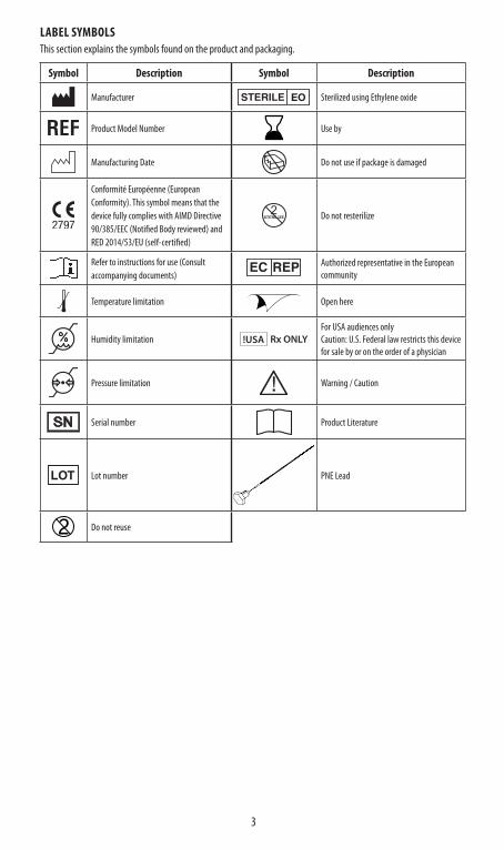
LABEL SYMBOLSThis section explains the symbols found on the product and packaging.
Symbol Description Symbol Description
Manufacturer Sterilized using Ethylene oxide
Product Model Number Use by
Manufacturing Date Do not use if package is damaged
Conformité Européenne (European Conformity). This symbol means that the device fully complies with AIMD Directive 90/385/EEC (Notified Body reviewed) and RED 2014/53/EU (self-certified)
Do not resterilize
Refer to instructions for use (Consult accompanying documents)
Authorized representative in the European community
Temperature limitation Open here
Humidity limitation !USA Rx ONLYFor USA audiences onlyCaution: U.S. Federal law restricts this device for sale by or on the order of a physician
Pressure limitation Warning / Caution
Serial number Product Literature
Lot number PNE Lead
Do not reuse
4
TABLE OF CONTENTS
LABEL SYMBOLS . . . . . . . . . . . . . . . . . . . . . . . . . . . . . . . . . . . . . . . . . . . . . . . . . . . . . . . . . . . . . . . . . . . . . . . . . . . .3
INTRODUCTION . . . . . . . . . . . . . . . . . . . . . . . . . . . . . . . . . . . . . . . . . . . . . . . . . . . . . . . . . . . . . . . . . . . . . . . . . . . . .5Purpose of the trial system . . . . . . . . . . . . . . . . . . . . . . . . . . . . . . . . . . . . . . . . . . . . . . . . . . . . . . . . . . . . . . . .5
DEVICE DESCRIPTION . . . . . . . . . . . . . . . . . . . . . . . . . . . . . . . . . . . . . . . . . . . . . . . . . . . . . . . . . . . . . . . . . . . . . . . .5Package contents . . . . . . . . . . . . . . . . . . . . . . . . . . . . . . . . . . . . . . . . . . . . . . . . . . . . . . . . . . . . . . . . . . . . . . . .5
CONTRAINDICATIONS . . . . . . . . . . . . . . . . . . . . . . . . . . . . . . . . . . . . . . . . . . . . . . . . . . . . . . . . . . . . . . . . . . . . . . . .6
WARNINGS . . . . . . . . . . . . . . . . . . . . . . . . . . . . . . . . . . . . . . . . . . . . . . . . . . . . . . . . . . . . . . . . . . . . . . . . . . . . . . . . .6Diathermy . . . . . . . . . . . . . . . . . . . . . . . . . . . . . . . . . . . . . . . . . . . . . . . . . . . . . . . . . . . . . . . . . . . . . . . . . . . . . .6Magnetic Resonance Imaging (MRI) . . . . . . . . . . . . . . . . . . . . . . . . . . . . . . . . . . . . . . . . . . . . . . . . . . . . . . . .6Electromagnetic interference (EMI) . . . . . . . . . . . . . . . . . . . . . . . . . . . . . . . . . . . . . . . . . . . . . . . . . . . . . . . . .6Case Damage . . . . . . . . . . . . . . . . . . . . . . . . . . . . . . . . . . . . . . . . . . . . . . . . . . . . . . . . . . . . . . . . . . . . . . . . . . . .7Effects on other implanted devices . . . . . . . . . . . . . . . . . . . . . . . . . . . . . . . . . . . . . . . . . . . . . . . . . . . . . . . . .7Unauthorized modifications to the Trial Stimulator . . . . . . . . . . . . . . . . . . . . . . . . . . . . . . . . . . . . . . . . . . .7
PRECAUTIONS . . . . . . . . . . . . . . . . . . . . . . . . . . . . . . . . . . . . . . . . . . . . . . . . . . . . . . . . . . . . . . . . . . . . . . . . . . . . . .7Clinician programming . . . . . . . . . . . . . . . . . . . . . . . . . . . . . . . . . . . . . . . . . . . . . . . . . . . . . . . . . . . . . . . . . . .7Patient activities . . . . . . . . . . . . . . . . . . . . . . . . . . . . . . . . . . . . . . . . . . . . . . . . . . . . . . . . . . . . . . . . . . . . . . . . .9Patient programming and Remote Control . . . . . . . . . . . . . . . . . . . . . . . . . . . . . . . . . . . . . . . . . . . . . . . . . .9Storage and Usage Environment . . . . . . . . . . . . . . . . . . . . . . . . . . . . . . . . . . . . . . . . . . . . . . . . . . . . . . . . . . .9 Sterilization . . . . . . . . . . . . . . . . . . . . . . . . . . . . . . . . . . . . . . . . . . . . . . . . . . . . . . . . . . . . . . . . . . . . . . . . . . .10System implant . . . . . . . . . . . . . . . . . . . . . . . . . . . . . . . . . . . . . . . . . . . . . . . . . . . . . . . . . . . . . . . . . . . . . . . . .10
POTENTIAL ADVERSE EVENTS SUMMARY . . . . . . . . . . . . . . . . . . . . . . . . . . . . . . . . . . . . . . . . . . . . . . . . . . . . . .10
INDIVIDUALIZATION OF TREATMENT . . . . . . . . . . . . . . . . . . . . . . . . . . . . . . . . . . . . . . . . . . . . . . . . . . . . . . . . . .11
PATIENT COUNSELING INFORMATION . . . . . . . . . . . . . . . . . . . . . . . . . . . . . . . . . . . . . . . . . . . . . . . . . . . . . . . . .11
COMPONENT DISPOSAL . . . . . . . . . . . . . . . . . . . . . . . . . . . . . . . . . . . . . . . . . . . . . . . . . . . . . . . . . . . . . . . . . . . . .11
SPECIFICATIONS . . . . . . . . . . . . . . . . . . . . . . . . . . . . . . . . . . . . . . . . . . . . . . . . . . . . . . . . . . . . . . . . . . . . . . . . . . .12
PNE LEAD IMPLANT PROCEDURE . . . . . . . . . . . . . . . . . . . . . . . . . . . . . . . . . . . . . . . . . . . . . . . . . . . . . . . . . . . . .12Procedure supplies . . . . . . . . . . . . . . . . . . . . . . . . . . . . . . . . . . . . . . . . . . . . . . . . . . . . . . . . . . . . . . . . . . . . . .12Procedure preparation . . . . . . . . . . . . . . . . . . . . . . . . . . . . . . . . . . . . . . . . . . . . . . . . . . . . . . . . . . . . . . . . . . .12Needle placement and test stimulation . . . . . . . . . . . . . . . . . . . . . . . . . . . . . . . . . . . . . . . . . . . . . . . . . . . .13PNE lead placement . . . . . . . . . . . . . . . . . . . . . . . . . . . . . . . . . . . . . . . . . . . . . . . . . . . . . . . . . . . . . . . . . . . . .14Connecting the Basic Trial Cable . . . . . . . . . . . . . . . . . . . . . . . . . . . . . . . . . . . . . . . . . . . . . . . . . . . . . . . . . . .16
PNE LEAD REMOVAL . . . . . . . . . . . . . . . . . . . . . . . . . . . . . . . . . . . . . . . . . . . . . . . . . . . . . . . . . . . . . . . . . . . . . . . .17
CUSTOMER SERVICE . . . . . . . . . . . . . . . . . . . . . . . . . . . . . . . . . . . . . . . . . . . . . . . . . . . . . . . . . . . . . . . . . . . . . . . .17
5
INTRODUCTIONThis manual provides information about the Axonics Sacral Neuromodulation (SNM) System PNE lead (Model 1901) and its implantation procedure. The peripheral nerve evaluation (PNE) lead is used in a basic trial with the Axonics Model 1601, external Trial Stimulator (TS). The TS is used to provide temporary electrical stimulation to the S3 or S4 sacral nerve, and this stimulation with the PNE lead is intended to not exceed 7 days. The PNE lead connects to the Basic Trial Cable (Axonics Model 1701). This cable is then connected to the TS. The TS creates a series of electrical pulses to stimulate the sacral nerve. A set of accessories is used to implant the PNE lead. This includes procedure-specific surgical tools and stimulation cables (Axonics Model 1701) and a Clinician Programmer (CP) (Axonics Model 2501). Instructions for connections to the TS are found in the TS manual.
Purpose of the trial systemThe Axonics SNM Trial System is used for a test period to evaluate if a subject should be treated with the Axonics SNM System.
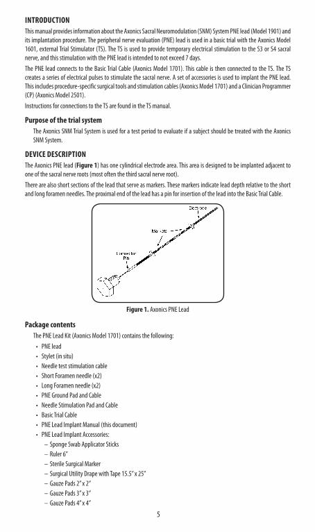
DEVICE DESCRIPTIONThe Axonics PNE lead (Figure 1) has one cylindrical electrode area. This area is designed to be implanted adjacent to one of the sacral nerve roots (most often the third sacral nerve root). There are also short sections of the lead that serve as markers. These markers indicate lead depth relative to the short and long foramen needles. The proximal end of the lead has a pin for insertion of the lead into the Basic Trial Cable.
Figure 1 . Axonics PNE Lead
Package contentsThe PNE Lead Kit (Axonics Model 1701) contains the following:
• PNE lead • Stylet (in situ)• Needle test stimulation cable• Short Foramen needle (x2)• Long Foramen needle (x2)• PNE Ground Pad and Cable• Needle Stimulation Pad and Cable• Basic Trial Cable• PNE Lead Implant Manual (this document)• PNE Lead Implant Accessories:
– Sponge Swab Applicator Sticks– Ruler 6”– Sterile Surgical Marker– Surgical Utility Drape with Tape 15.5” x 25”– Gauze Pads 2” x 2”– Gauze Pads 3” x 3”– Gauze Pads 4” x 4”
6
– Tegaderm 2 3/8” x 2 ¾” – Tegaderm 4” x 4 ¾” – Syringe 10mL– Syringe Needle, 25 Gauge x 1.5– Medicine Cup 2oz./60cc
• The contents of the kit (except for PNE Ground Pad and Cable, Needle Stimulation Pad and Cable, and Basic Trial Cable) are STERILE. All components are intended for single use only.
CAUTION• Sterile components should be discarded if their sterility is compromised. Check to ensure packaging is intact
prior to opening. Do not clean and reuse or re-sterilize any sterile items that make contact outside a sterile field. • Each component of the Axonics SNM System is designed for use only with the other components and
accessories of the Axonics SNM System. The components and accessories of the Axonics SNM System should not be used with any other neuromodulation systems.
CONTRAINDICATIONSThe Axonics SNM Trial System is contraindicated for patients who are unable to operate the Axonics SNM Trial System.
WARNINGSDiathermy
Do not use shortwave diathermy, microwave diathermy, or therapeutic ultrasound diathermy (collectively described as diathermy) on patients implanted with the Axonics SNM System. Diathermy can transmit energy through the implanted system, potentially causing tissue damage at the location of the implanted electrodes. This could result in severe injury.
Magnetic Resonance Imaging (MRI)An MRI should not be conducted on an individual undergoing a trial period of SNM therapy utilizing the external TS.The following additional medical procedures that may affect the Axonics SNM System should be avoided during the trial period:
• Lithotripsy• Monopolar electro surgery• Microwave and Radio-frequency (RF) ablation• Radiation therapy • Ultrasound or scanning equipment
Electromagnetic interference (EMI)EMI is energy that can interfere with the function of the Axonics SNM System. This energy can be generated by equipment found at home, work, or in public. The Axonics SNM System includes features that provide protection from EMI. Most electrical devices encountered in a normal day are unlikely to affect the operation of the TS. While everyday electrical devices are unlikely to affect the TS, there are strong sources of EMI that pose a higher risk. These include theft detectors, security gates, and security wands. If patients encounter any of these electrical devices, they should walk far away from the sides of the device when passing through. Additionally, patients should minimize their exposure to these devices by not lingering in the immediate area of the device. Sources of strong EMI can result in the following:
• Serious patient injury, resulting from heating of the TS and/or leads. This may damage the surrounding tissue.• System damage, which may require surgical replacement due to change in symptom control.• Operational changes to the TS, causing it to turn on or off or to reset the settings. This will result in loss of
stimulation or return of symptoms. Reprogramming by the clinician may be needed.• Unexpected changes in stimulation, which may be experienced as a jolting or shocking sensation. While the
sensation may be uncomfortable, the device would not be damaged nor would it cause direct injury to the patient. In rare cases, the change in stimulation may cause the patient to fall and be injured.
7
Case DamageThe TS contains battery chemicals that could cause severe burns if the case were ruptured or pierced.
Effects on other implanted devicesThe effect of the Axonics SNM System on the operation of other implanted devices is not known. This includes devices such as cardiac devices, other Neurostimulators, and implantable drug pumps. In particular, if the Axonics device is on the body near one of these devices, they may have sensing problems and/or inappropriate device responses. Clinicians involved with both devices should investigate potential interference issues before surgery. The programming of the devices may need to be optimized to provide maximum benefit from both devices.TS interaction with implanted cardiac devices – When a patient needs both an Axonics SNM System and an implanted cardiac device, interactions between the two devices should be discussed by the patients’ physicians before surgery. Such devices may include pacemakers or defibrillators. The physicians involved may include cardiologists, electrophysiologists, urologists, and urogynecologists. To reduce potential interference, the TS device should be worn on the opposite side of the body. It should also be worn as far away from the cardiac device as practical. The stimulation pulses produced by the Axonics SNM System may interact with cardiac devices that sense cardiac activity. This may lead to inappropriate behavior of the cardiac device.
Unauthorized modifications to the Trial StimulatorNo modification of any component of the Axonics SNM System is allowed. Modification may result in more risks and hazards.
PRECAUTIONSClinician programming
Parameter adjustment – The steps below should be taken to prevent sudden stimulation changes that lead to an uncomfortable jolting or shocking feeling.
• Stimulation parameters should be changed in small increments.• The stimulation amplitude should be allowed to ramp to full amplitude slowly.• Before disconnecting the stimulation cable or turning the simulation on or off, the stimulation amplitude should
be decreased to 0.0 mA.Sensitivity to stimulation –Patients who are very sensitive to stimulation may be able to sense the telemetry signals associated with reprogramming. Programmer interaction with a cochlear implant – Patients with cochlear implants should keep the external portion of their cochlear implant as far from the Clinician Programmer (CP) or Remote Control as possible. This will help minimize unintended audible clicks or other sounds.Programmer interaction with flammable atmospheres – The CP is not intended to be used in the presence of a flammable gases. The consequences of using the CP in such an environment is not known.Programmer interaction with other active implanted devices – When a patient has a TS and another active implanted device the RF signal used to program any of these devices may reset or reprogram the other devices. These devices include a pacemaker, defibrillator, or another neurostimulator.Whenever the settings for these devices are changed, a clinician familiar with each device should check the program settings of each device before the patient is released (or as soon as possible). Patients should contact their physician immediately if they experience symptoms that are likely to be related to the devices or their medical condition.Telemetry signal disruption from EMI – The TS should not be programmed near equipment that may generate EMI. The equipment may interfere with the CP or Remote Control’s ability to communicate with the TS. If EMI is suspected to be interrupting programming, the CP or the Remote Control and the TS should be moved away from the likely source of EMI. Interference during medical imaging – The TS should be turned off, disconnected, and removed prior to medical imaging (x-ray, CT). The components of the trial system may distort images or impede the ability to see certain internal structures when performing imaging tests.

8
Electromagnetic Interference (EMI)Patients may encounter additional equipment that generates EMI. This equipment is unlikely to affect the Axonics SNM System if the patients follows these guidelines: Bone growth stimulators – The external coils of bone growth stimulators should be kept at least 45 cm (18 in) away from the Axonics SNM System. Do not use a bone growth stimulator if it is not working as intended. Dental drills and ultrasonic probes –The drill or probe should be kept 15 cm (6 in) away from the Stimulator. The Stimulator should be turned off. Electrolysis – The electrolysis wand should be kept at least 15 cm (6 in) away from the Stimulator. The Stimulator should be turned off.Electromagnetic field devices – The following equipment or environments should be avoided or patients should exercise caution around:
• Antenna of citizens band (CB) radio or ham radio • Electric arc welding equipment • Electric induction heaters such as those used in industry to bend plastic • Electric steel furnaces • High-power amateur transmitters • High-voltage areas (generally safe if outside the fenced area) • Linear power amplifiers • Magnetic degaussing equipment • Magnets or other equipment that generates strong magnetic fields • Microwave communication transmitters (generally safe if outside the fenced area) • Perfusion systems • Resistance welders • Television and radio transmitting towers (generally safe if outside the fenced area)
Laser procedures – The laser should not be directed at the Stimulator. The Stimulator should be turned off. Psychotherapeutic procedures – Equipment used for psychotherapeutic procedures may induce electrical currents which may cause heating at the lead electrodes and could result in tissue damage. Equipment that generates electromagnetic interference (e.g., electroconvulsive therapy, transcranial magnetic stimulation) during psychotherapeutic procedures have not been established as safe to operate in a patient with a Stimulator. Induced electrical currents may cause heating, especially at the lead electrode site, resulting in tissue damage. Radiation therapy – Stimulator operation may be affected by high-radiation exposure. Sources of high-radiation should not be directed at the Stimulator. Stimulator damage due to high-radiation exposure may not be immediately evident, and exposure should be limited using appropriate measures, including shielding and adjusting the beam angle to avoid exposure to the Stimulator. Transcutaneous electrical nerve stimulation (TENS) – TENS electrodes should not be placed in locations where the TENS current passes over any component of the Axonics SNM System. Discontinue using TENS if it starts affecting the performance of the Axonics SNM System. If a patient thinks that an EMI generating equipment or environment is affecting the function of their Axonics SNM System, the patient should: 1. Move away from the equipment or object. 2. Turn off the equipment or object. (if possible) 3. Use the patient Remote Control to adjust stimulation if necessary and to confirm the system is functioning
appropriately. If the patient is unable to eliminate the interference or believes the interference has altered the effectiveness of their therapy, the patient should contact their clinician.Sources of strong EMI can result in the following:
• Serious patient injury, resulting from heating of the Stimulator and/or leads. This may damage the surrounding tissue.
• System damage, which may require surgical replacement due to change in symptom control.• Operational changes to the Stimulator, causing it to turn on or off or to reset the settings, resulting in
unexpected changes of stimulation and return of symptoms. Reprogramming by the clinician may be needed.
9
Unexpected changes in stimulation, leading to a sudden increase or change in stimulation, which may be experienced as a jolting or shocking sensation. While the sensation may be uncomfortable, the device would not be damaged nor would it cause direct injury to the patient. In rare cases, the change in stimulation may cause the patient to fall and be injured.
Patient activitiesActivities requiring excessive twisting or stretching – Patients should avoid activities that may strain the implanted components of the Axonics SNM System. For example, movements that include bending, twisting, bouncing, or stretching may pull on the connection between the TS and lead(s). This may cause movement of the lead or discomfort. It may also result in an unsuccessful trial period due to lack of adequate stimulation of the sacral nerve. Clinicians should ask their patients about the activities in which they participate and inform them of the need for restricted activities.Component manipulation by patient (Twiddler’s syndrome) – Clinicians should advise patients to refrain from manipulating the Axonics SNM System through the skin. Manipulation may cause device damage, lead migration, skin erosion, or uncomfortable stimulation.Scuba diving or hyperbaric chambers – Patients should not scuba dive or use a hyperbaric chamber during their trial stimulation period.Skydiving, skiing, or hiking in the mountains – Patients should not sky-dive, ski or go hiking during the trial stimulation period.Unexpected changes in stimulation – EMI, postural changes, and other activities may cause a perceived increase in stimulation. Some patients may find this uncomfortable (a jolting or shocking feeling). Before engaging in activities where receiving a jolt would be unsafe for the patient or those around them, patients should lower the stimulation amplitude to the lowest setting and turn off the TS. Patients should also discuss these activities with their clinician.Showering and bathing during the trial stimulation period – Patients should not expose the TS to water during the trial stimulation period. They may take sponge baths during the trial stimulation period. However patients will have to remove the TS and keep their lead implant site and their surgical dressings dry. Patients should be advised on avoiding showers and baths by their physician.
Patient programming and Remote ControlPatient access to Remote Control – Patients should carry their Remote Control with them at all times. This will allow them to adjust the stimulation amplitude and/or turn on/off the TS.Remote Control may affect other implanted devices – Patients should avoid placing the Remote Control over or near other active implanted medical devices (for example pacemaker, defibrillator and other neurostimulators). Remote Control handling – Patients should avoid immersing the Remote Control in liquid to avoid damaging it. Patients should also avoid dropping the device or mishandling it in any way that may damage it. Patients should clean the device with water and a soft cloth. Remote Control use – Patients should avoid operating the Remote Control when near flammable or explosive gases.
Storage and Usage EnvironmentComponent packaging – Do not implant the component if any of the following have occurred:
• The storage package or sterile pack has been damaged, pierced, or altered. In this case, sterility cannot be guaranteed and infection may occur.
• The component itself shows any signs of damage. The component may not function properly.• The use-by date has expired. In this case, component performance cannot be guaranteed.
Usage environmentThe following lists the appropriate temperature, humidity, and pressure condition for use of the Axonics components:
• Temperature (Lead and accessories): 5 °C to 40 °C • Humidity (Lead and accessories): 15% to 95%• Pressure (Lead and accessories): 70 kPa to 106 kPa
10
Shipping and Storage environmentThe following lists the appropriate temperature, humidity, and pressure condition for shipping and storage of Axonics components:
• Temperature (short term: 3 days, Lead and accessories): -25 °C to 70 °C • Temperature (long term, Lead and accessories): 20 °C to 30 °C • Humidity (short term: 3 days, Lead and accessories): 15% to 95%• Humidity (long term, Lead and accessories): 15% to 95%• Pressure (short term: 3 days, Lead and accessories): 57 kPa to 106 kPa• Pressure (long term, Lead and accessories): 70 kPa to 106 kPa
If the components were stored at temperatures outside of the operating range, do not use them until they have returned to the operating temperature range.
SterilizationContents* of this package have been sterilized using ethylene oxide. This device is for single use only and should not be re-sterilized..
System implantCompatibility – For proper therapy, use only Axonics SNM components. The use of non-Axonics components with the Axonics SNM System may result in damage to Axonics components, loss of stimulation, or patient injury.Use of non-Axonics components will void Axonics warranty coverage.Component failures – The components of the Axonics SNM System may fail at any time. The PNE lead should provide at least 7 days of service. Unexpected stress, strain, or impact can cause earlier failure. Such failures, such as electrical shorts, open circuits, and insulation breaches are unpredictable. Also, the TS battery will eventually run out and can provide no more than 60 days of stimulation.Component handling – Handle the components of the Axonics SNM System with extreme care. They may be damaged by excessive force or sharp instruments. Such damage can lead to intermittent stimulation or loss of stimulation altogether and may require surgery to replace.
POTENTIAL ADVERSE EVENTS SUMMARYImplantation and use of the Axonics SNM System incurs risk beyond those normally associated with surgery. Some risks may necessitate surgical intervention. These risks include, but are not limited to the following:
• Adverse change in voiding function (bowel and/or bladder).• Allergic or immune system response to the implanted materials that could result in device rejections.• Change in sensation or magnitude of stimulation which has been described as uncomfortable (jolting or
shocking) by some patients.• Device fracture/failure• Device migration• Electrical shock• Infection.• Pain or irritation at Stimulator and/or lead site.• Seroma, hemorrhage, and/or hematoma. • Suspected lead migration or erosion.• Suspected nerve injury (including numbness).• Suspected technical device malfunctions.• Transient electric shock or tingling.• Unintended nerve activation.• Heating or burn at Stimulator site.• Lack of efficacy• Reoperation/Revision• Undesirable change in pelvic function
*Non-sterile contents include the PNE Ground Pad and Cable, Needle Stimulation Pad and Cable, and the Basic Trial Cable
11
INDIVIDUALIZATION OF TREATMENTFully inform the patient about the risks and benefits of SNM therapy. This includes risks of the surgical procedure, follow-up responsibilities, and self-care requirements. In order to achieve optimal benefits from the therapy, the Axonics SNM System requires a long-term commitment to post-surgical management.
Patient selection – Select the patients carefully to ensure they meet the following criteria:• The patient is an appropriate surgical candidate. Give special consideration for the lead length, implant depth,
and ability to successfully implant the lead and route the lead to the Neurostimulator.• The patient can properly operate the Axonics SNM System. This includes the ability to use the Remote Control, to
detect alignment of the Charger, and to understand when charging is complete.• If the patient underwent a test stimulation period, he/she received satisfactory results.• The patient does not have a history of sensitivity to stimulation.
PATIENT COUNSELING INFORMATIONClinicians should provide the following:
• Information about the components of the Axonics SNM System.• Instructions for using the Remote Control.
Also, the clinician should provide each patient with a copy of the Axonics SNM Trial System Guide. The clinician should review the following sections with him/her:
• Getting the Trial System.• The Test Period
Clinicians should also instruct their patients as follows:• Patients should tell their healthcare professionals, including their primary doctor and dentist, that they have
a trial neuromodulation system. Patients should bring their Trial System Guide to all medical and dental appointments. This will help resolve any questions that their healthcare professional may have regarding any precautions to take to avoid potential device problems.
• Patients should always carry their Remote Control. This allows them to change the stimulation amplitude and/or turn the TS on or off.
• Patients should always bring their Remote Control to appointments related to their Axonics SNM System, including all programming sessions.
• Patients should contact their physician if they have any unusual signs or symptoms.
COMPONENT DISPOSALThe following steps should be taken when the Axonics SNM System is explanted (for example, due to replacement, cessation of therapy, or after patient death) or when disposing of accessories:
• If possible, the explanted component should be returned to Axonics along with completed paperwork for analysis and disposal.
• The device should not be autoclaved or exposed to ultrasonic cleaners to allow it to be analyzed by Axonics.• Any components not returned to Axonics should be disposed of according to local regulations. Any potentially
contaminated materials should be treated as biohazardous waste.
CAUTIONS• Components that are explanted or that have come into contact with bodily fluids should be handled with
appropriate biohazard controls. Such components should only be returned to Axonics in packaging supplied by Axonics.
• The TS may explode if subjected to high temperatures. Therefore, the TS should not be incinerated.• Implantable devices should not be reused after exposure to body tissues or fluids. The sterility and
functionality of these devices cannot be assured.
12
SPECIFICATIONSTable 1 shows the PNE lead specifications. For detailed descriptions and specifications for other components and accessories, refer to the product literature packaged with those devices.
Table 1 . PNE Lead specifications
Physical Properties
Lead length 41 cm
Number of electrodes 1
Electrode length 10 mm
Materials
• Conductor wire Stainless steel
• Proximal connector Stainless steel
• Stimulating electrodes Stainless steel
• Conductor wires Insulation Fluoropolymer
Note: All dimensions are approximate.
PNE LEAD IMPLANT PROCEDUREThe following section describes the procedure for implanting the Axonics PNE lead.
Procedure suppliesIn addition to the surgical tools required by the physician, the following supplies are needed for the implantation of the PNE lead:
• Axonics PNE Implant Kit (Model 1701).• PNE lead (optional for bilateral lead implantation) (Model 1901).
Procedure preparation1. Place the patient prone. Create an approximate 30° flexion at the hip and knees. Place a pillow underneath the
patient abdomen/hips if necessary. This will help flatten the sacrum in the horizontal plane.2. Prep the patient’s lower back out laterally to the hips. Extend the prep down to the buttocks, perianal area and
perineum for sterile surgery.3. Administer local anesthesia in the area of the targeted sacral foramen. Inject anesthesia down to the sacrum. 4. Affix the stimulation ground pad (non-sterile) to the skin.
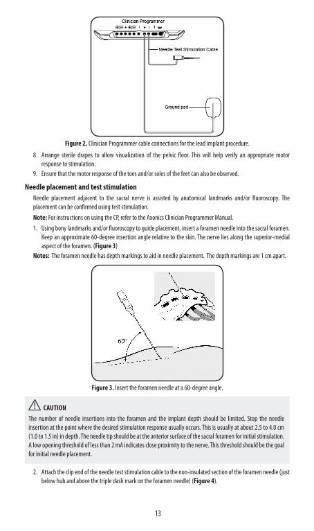
a. Clean and dry skin area where ground pad is to be affixed (trimming hair from area is often helpful).b. Open the pouch of the ground pad.c. Peel the plastic packing off the ground pad.d. Apply ground pad to the skin area. Hold in place for 15 seconds.e. Insert the black plug into the CP ground ( ) next to Needle Test Stimulation Cable (Figure 2).
5. Remove the needle test stimulation cable from the packaging.6. Ensure that the stimulation amplitude on the CP is set to zero.7. Insert the black plug of the needle test stimulation cable into the CP outside the sterile field (Figure 2). Keep
the clip end of the cable in the sterile field.Note: Ensure all cable connections are secure.
13
Figure 2 . Clinician Programmer cable connections for the lead implant procedure.
8. Arrange sterile drapes to allow visualization of the pelvic floor. This will help verify an appropriate motor response to stimulation.
9. Ensure that the motor response of the toes and/or soles of the feet can also be observed.
Needle placement and test stimulationNeedle placement adjacent to the sacral nerve is assisted by anatomical landmarks and/or fluoroscopy. The placement can be confirmed using test stimulation.Note: For instructions on using the CP, refer to the Axonics Clinician Programmer Manual.1. Using bony landmarks and/or fluoroscopy to guide placement, insert a foramen needle into the sacral foramen.
Keep an approximate 60-degree insertion angle relative to the skin. The nerve lies along the superior-medial aspect of the foramen. (Figure 3)
Notes: The foramen needle has depth markings to aid in needle placement. The depth markings are 1 cm apart.
Figure 3 . Insert the foramen needle at a 60-degree angle.
CAUTIONThe number of needle insertions into the foramen and the implant depth should be limited. Stop the needle insertion at the point where the desired stimulation response usually occurs. This is usually at about 2.5 to 4.0 cm (1.0 to 1.5 in) in depth. The needle tip should be at the anterior surface of the sacral foramen for initial stimulation. A low opening threshold of less than 2 mA indicates close proximity to the nerve. This threshold should be the goal for initial needle placement.
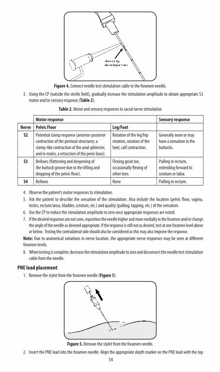
2. Attach the clip end of the needle test stimulation cable to the non-insulated section of the foramen needle (just below hub and above the triple dash mark on the foramen needle) (Figure 4).
14
Figure 4 . Connect needle test stimulation cable to the foramen needle.
3. Using the CP (outside the sterile field), gradually increase the stimulation amplitude to obtain appropriate S3 motor and/or sensory response (Table 2).
Table 2 . Motor and sensory responses to sacral nerve stimulation
Motor response Sensory responseNerve Pelvic Floor Leg/Foot
S2 Potential clamp response (anterior-posterior contraction of the perineal structures; a clamp-like contraction of the anal sphincter, and in males, a retraction of the penis base).
Rotation of the leg/hip rotation, rotation of the heel, calf contraction.
Generally none or may have a sensation in the buttocks.
S3 Bellows (flattening and deepening of the buttock groove due to the lifting and dropping of the pelvic floor).
Flexing great toe, occasionally flexing of other toes.
Pulling in rectum, extending forward to scrotum or labia.
S4 Bellows None Pulling in rectum.
4. Observe the patient’s motor responses to stimulation.5. Ask the patient to describe the sensation of the stimulation. Also include the location (pelvic floor, vagina,
testes, rectum/anus, bladder, scrotum, etc.) and quality (pulling, tapping, etc.) of the sensation.6. Use the CP to reduce the stimulation amplitude to zero once appropriate responses are noted.7. If the desired responses are not seen, reposition the needle higher and more medially in the foramen and/or change
the angle of the needle as deemed appropriate. If the response is still not as desired, test at one foramen level above or below. Testing the contralateral side should also be considered as this may also improve the response.
Note: Due to anatomical variations in nerve location, the appropriate nerve responses may be seen at different foramen levels.8. When testing is complete, decrease the stimulation amplitude to zero and disconnect the needle test stimulation
cable from the needle.
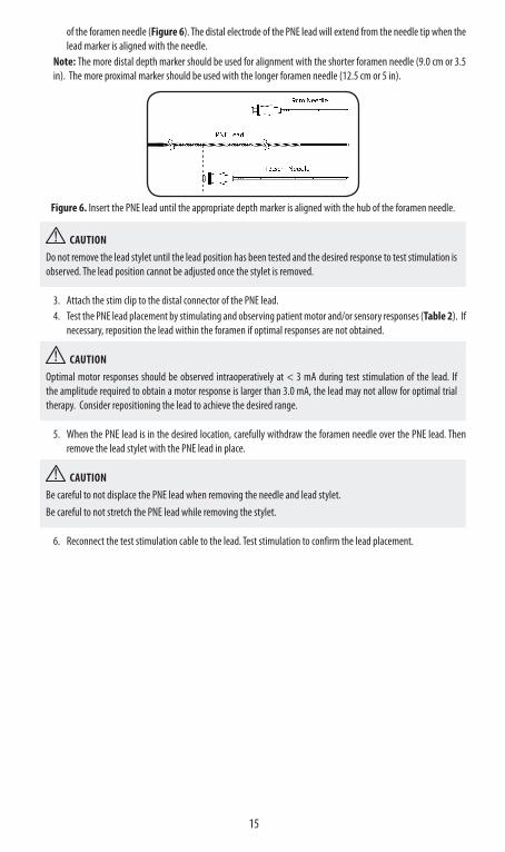
PNE lead placement1. Remove the stylet from the foramen needle (Figure 5).
Figure 5 . Remove the stylet from the foramen needle.
2. Insert the PNE lead into the foramen needle. Align the appropriate depth marker on the PNE lead with the top
15
of the foramen needle (Figure 6). The distal electrode of the PNE lead will extend from the needle tip when the lead marker is aligned with the needle.
Note: The more distal depth marker should be used for alignment with the shorter foramen needle (9.0 cm or 3.5 in). The more proximal marker should be used with the longer foramen needle (12.5 cm or 5 in).
Figure 6 . Insert the PNE lead until the appropriate depth marker is aligned with the hub of the foramen needle.
CAUTIONDo not remove the lead stylet until the lead position has been tested and the desired response to test stimulation is observed. The lead position cannot be adjusted once the stylet is removed.
3. Attach the stim clip to the distal connector of the PNE lead.4. Test the PNE lead placement by stimulating and observing patient motor and/or sensory responses (Table 2). If
necessary, reposition the lead within the foramen if optimal responses are not obtained.
CAUTIONOptimal motor responses should be observed intraoperatively at < 3 mA during test stimulation of the lead. If the amplitude required to obtain a motor response is larger than 3.0 mA, the lead may not allow for optimal trial therapy. Consider repositioning the lead to achieve the desired range.
5. When the PNE lead is in the desired location, carefully withdraw the foramen needle over the PNE lead. Then remove the lead stylet with the PNE lead in place.
CAUTIONBe careful to not displace the PNE lead when removing the needle and lead stylet. Be careful to not stretch the PNE lead while removing the stylet.
6. Reconnect the test stimulation cable to the lead. Test stimulation to confirm the lead placement.
16
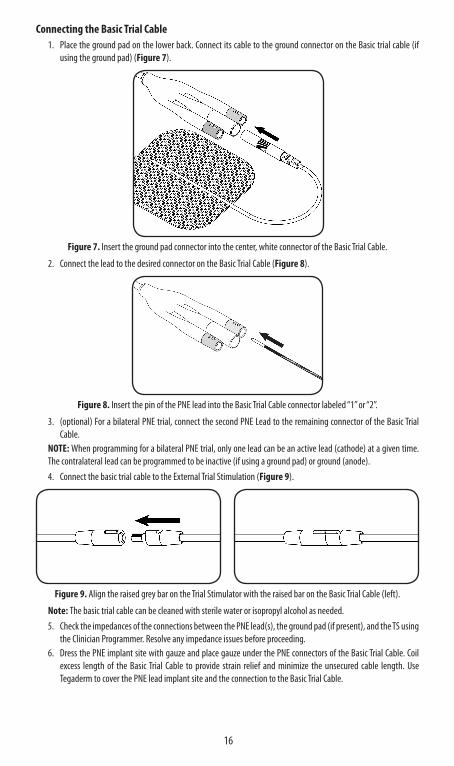
Connecting the Basic Trial Cable1. Place the ground pad on the lower back. Connect its cable to the ground connector on the Basic trial cable (if
using the ground pad) (Figure 7).
Figure 7 . Insert the ground pad connector into the center, white connector of the Basic Trial Cable.
2. Connect the lead to the desired connector on the Basic Trial Cable (Figure 8).
Figure 8 . Insert the pin of the PNE lead into the Basic Trial Cable connector labeled “1” or “2”.
3. (optional) For a bilateral PNE trial, connect the second PNE Lead to the remaining connector of the Basic Trial Cable.
NOTE: When programming for a bilateral PNE trial, only one lead can be an active lead (cathode) at a given time. The contralateral lead can be programmed to be inactive (if using a ground pad) or ground (anode).4. Connect the basic trial cable to the External Trial Stimulation (Figure 9).
Figure 9 . Align the raised grey bar on the Trial Stimulator with the raised bar on the Basic Trial Cable (left).
Note: The basic trial cable can be cleaned with sterile water or isopropyl alcohol as needed.5. Check the impedances of the connections between the PNE lead(s), the ground pad (if present), and the TS using
the Clinician Programmer. Resolve any impedance issues before proceeding.6. Dress the PNE implant site with gauze and place gauze under the PNE connectors of the Basic Trial Cable. Coil
excess length of the Basic Trial Cable to provide strain relief and minimize the unsecured cable length. Use Tegaderm to cover the PNE lead implant site and the connection to the Basic Trial Cable.
17
PNE LEAD REMOVALAt the end of trial stimulation period, the PNE lead should be removed. 1. Turn off TS stimulation. Disconnect all cables. Refer to the TS manual for instructions on turning off the TS.2. Gentle traction can be used to remove the lead. 3. Follow the appropriate protocol for disposal of biohazardous waste. For e.g. to dispose of the PNE lead, the trial
cables, and surgical dressings.
CUSTOMER SERVICEFor questions regarding the Axonics SNM System, call our Customer Support Center toll-free at +1-877-929-6642.Additional information and product manuals can be found at our website: www.axonics.com

Page left intentionally blank

Page left intentionally blank
HealthLink Europe Services BVDe Tweeling 20-225215 MC ’s – HertogenboschThe Netherlands
All Rights Reserved. Copyright 2019.Axonics Modulation Technologies
(10-23-2019) 110-0131-001 rev A