Sabine DENIS Institut Jean Lamour, UMR 7198 CNRS...
58
Heat Treatment Processes Institut Jean Lamour, UMR 7198 CNRS - Université de Lorraine Parc de Saurupt, 54011 Nancy Cedex France Sabine DENIS ANF Métallurgie fondamentale 22-25 oct 2012, Aussois
Transcript of Sabine DENIS Institut Jean Lamour, UMR 7198 CNRS...
Heat Treatment Processes
Institut Jean Lamour, UMR 7198 CNRS - Université de Lorraine Parc de Saurupt, 54011 Nancy Cedex France
Sabine DENIS
ANF Métallurgie fondamentale 22-25 oct 2012, Aussois
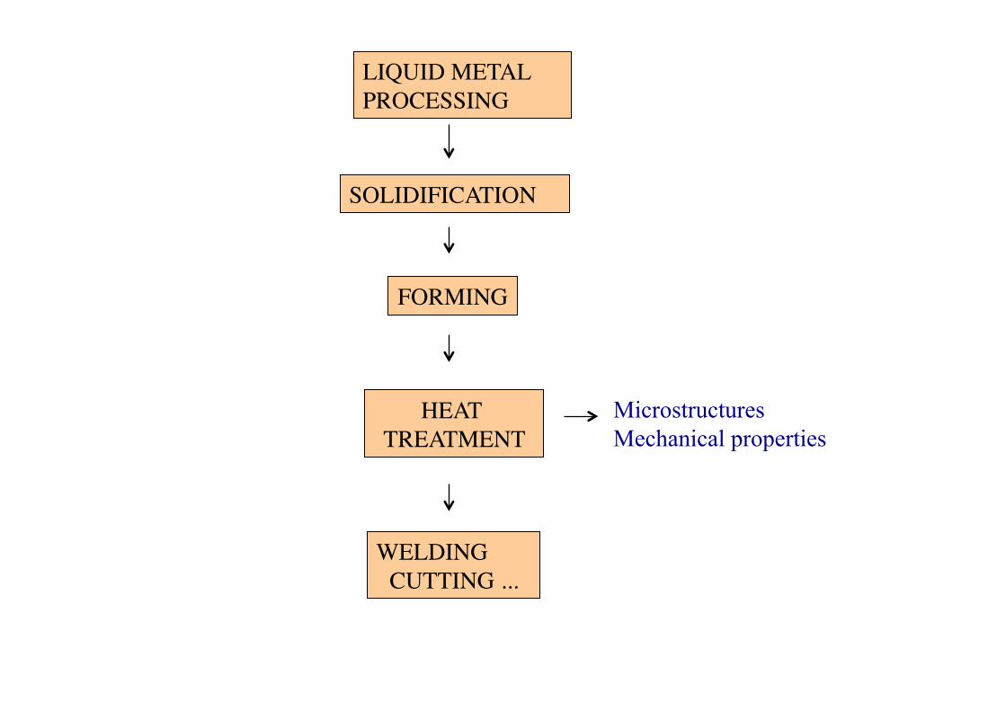
SOLIDIFICATION
FORMING
HEAT TREATMENT
WELDING CUTTING ...
LIQUID METAL PROCESSING
Microstructures Mechanical properties
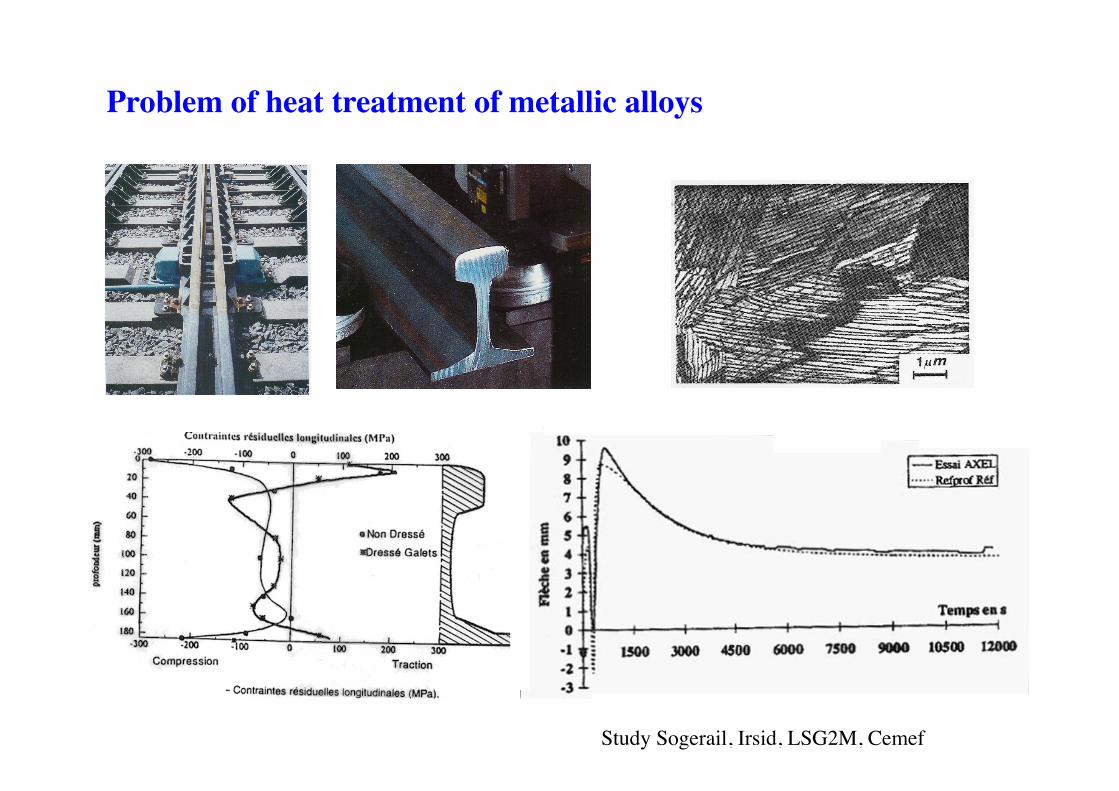
Problem of heat treatment of metallic alloys
Etude Sogerail, Irsid, LSG2M, Cemef Study Sogerail, Irsid, LSG2M, Cemef
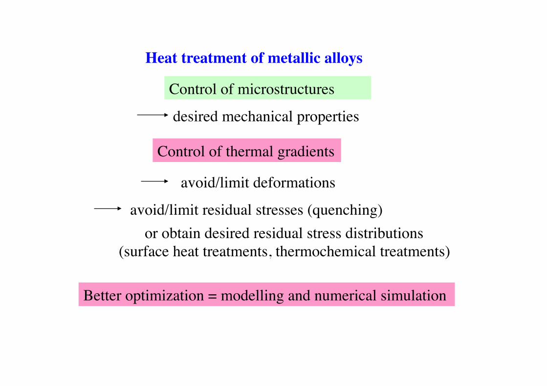
Heat treatment of metallic alloys
Control of microstructures
desired mechanical properties
Control of thermal gradients
avoid/limit deformations
avoid/limit residual stresses (quenching) or obtain desired residual stress distributions
(surface heat treatments, thermochemical treatments)
Better optimization = modelling and numerical simulation
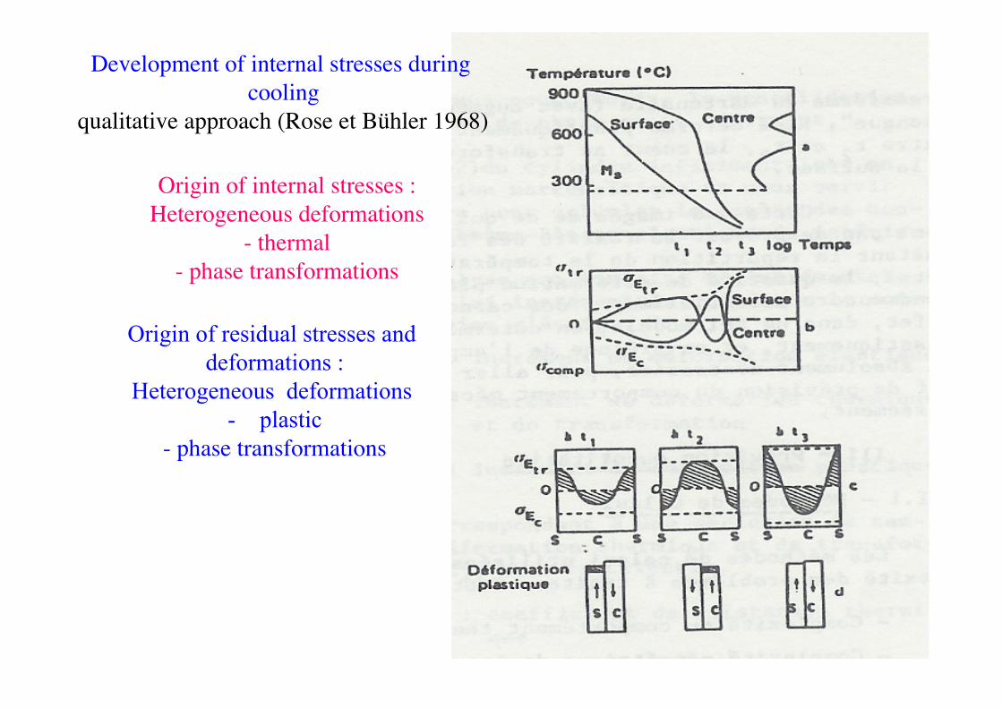
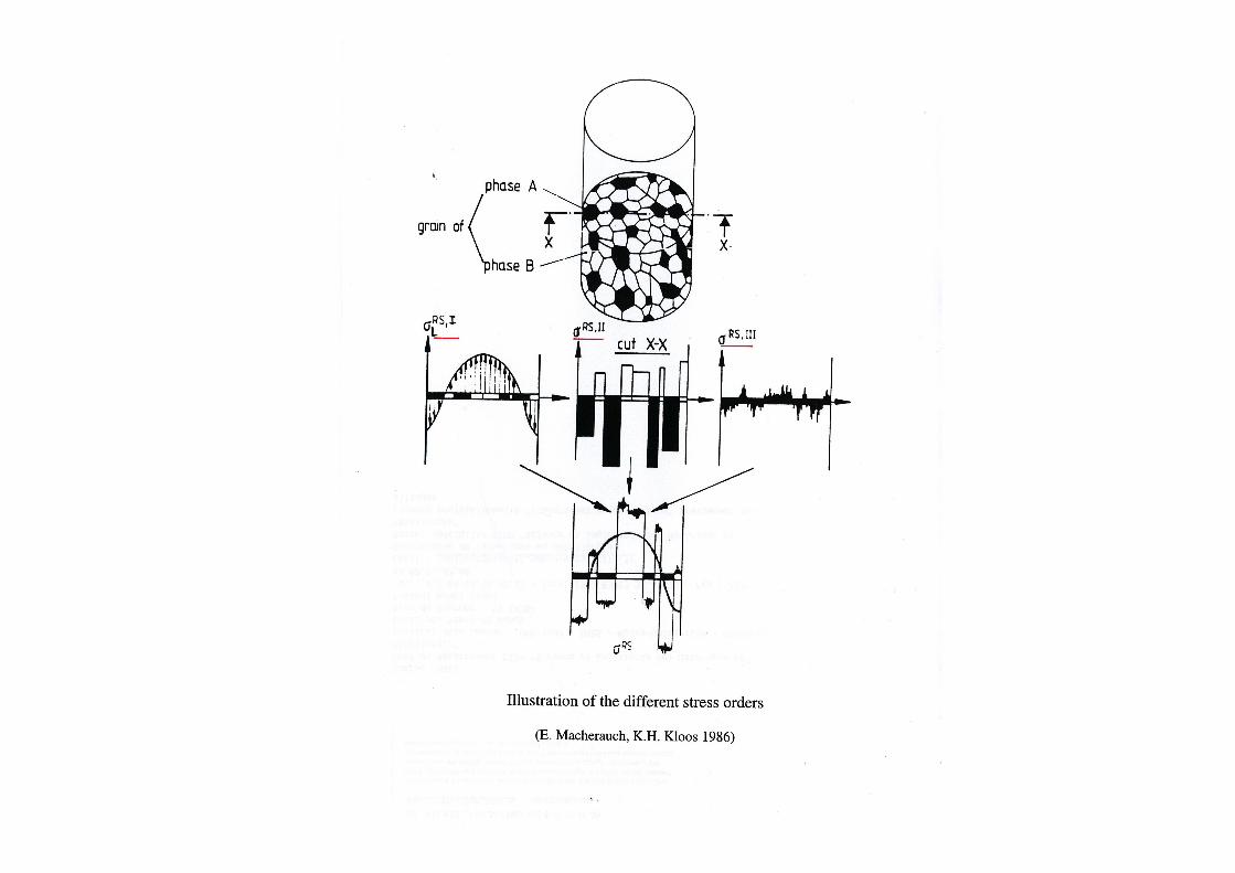
Development of internal stresses during cooling
qualitative approach (Rose et Bühler 1968)
Origin of internal stresses : Heterogeneous deformations
- thermal - phase transformations
Origin of residual stresses and deformations :
Heterogeneous deformations - plastic
- phase transformations
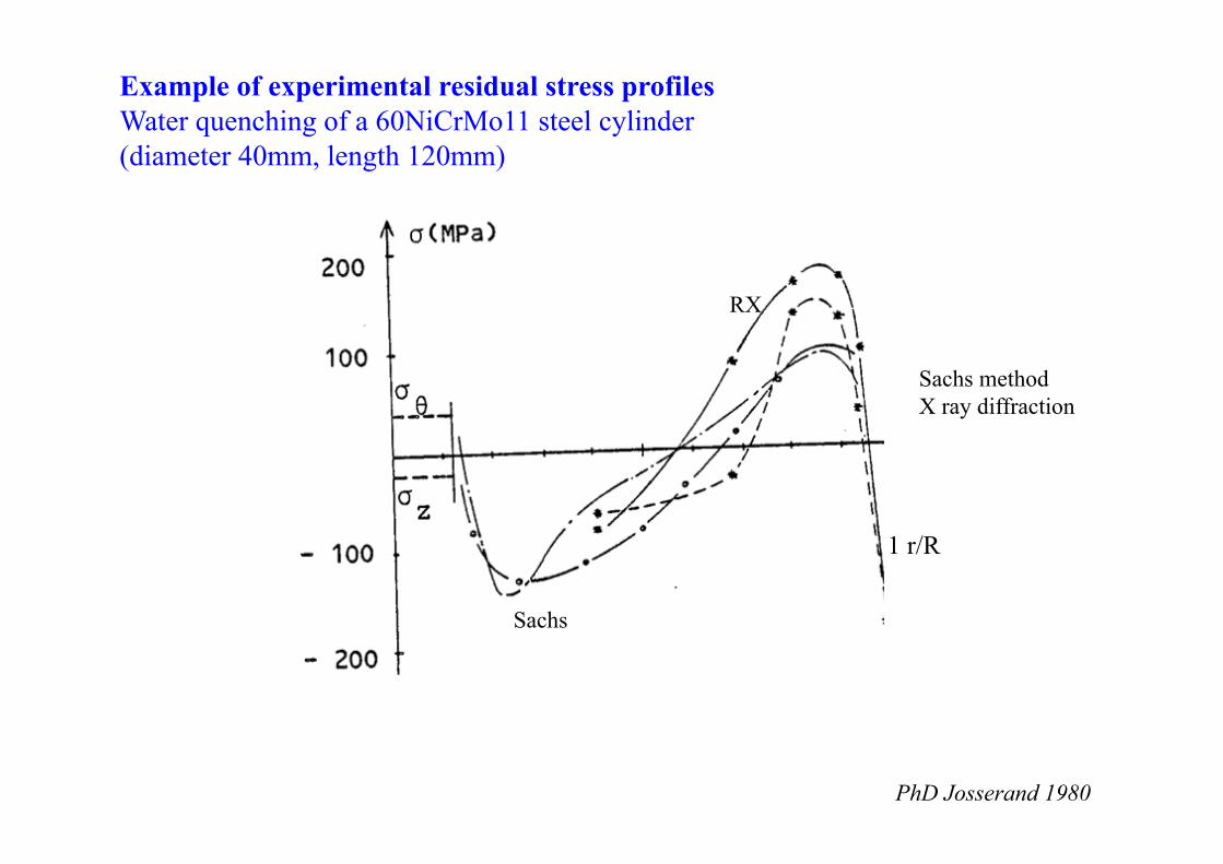
Example of experimental residual stress profiles Water quenching of a 60NiCrMo11 steel cylinder (diameter 40mm, length 120mm)
Sachs method X ray diffraction
1 r/R
RX
Sachs
PhD Josserand 1980
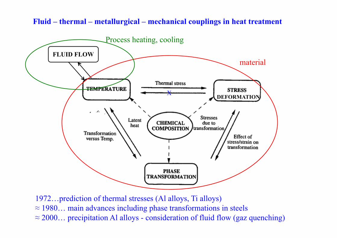
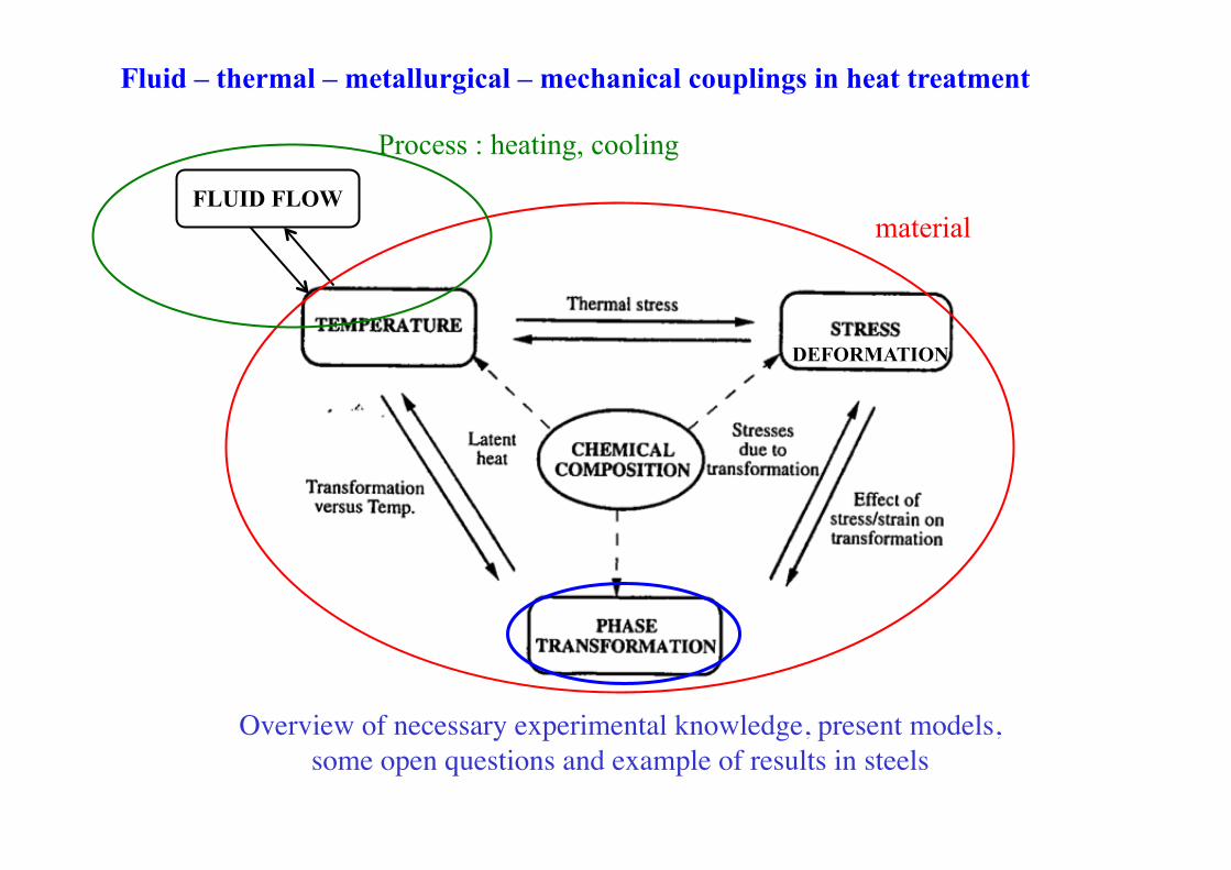
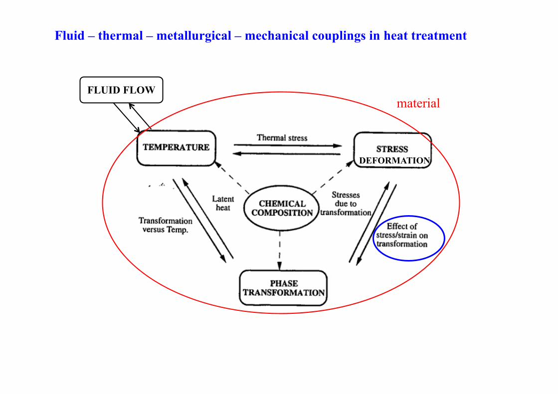
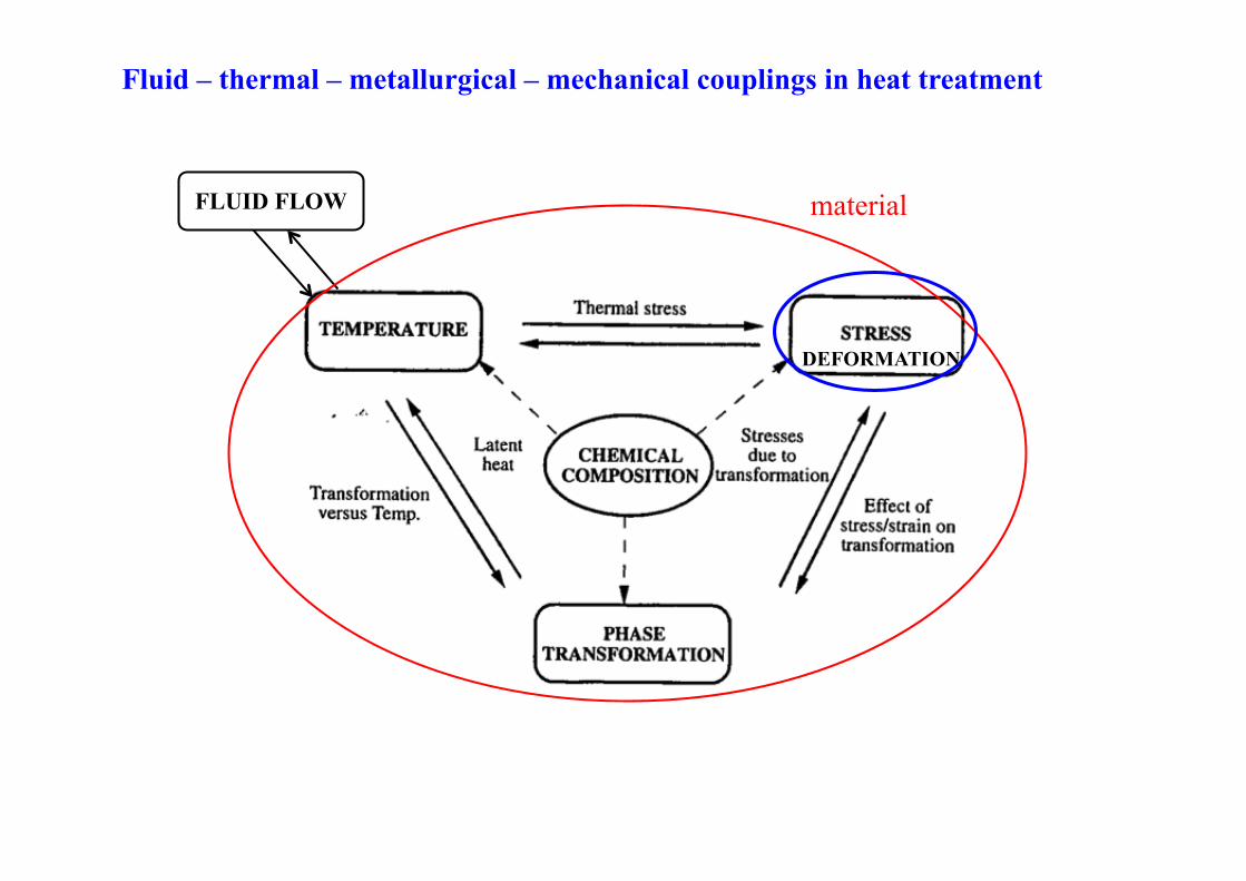
Fluid – thermal – metallurgical – mechanical couplings in heat treatment
FLUID FLOW material
Process heating, cooling
1972 …prediction of thermal stresses (Al alloys, Ti alloys) ≈ 1980… main advances including phase transformations in steels ≈ 2000… precipitation Al alloys - consideration of fluid flow (gaz quenching)
DEFORMATION X
Fluid – thermal – metallurgical – mechanical couplings in heat treatment
FLUID FLOW material
Process : heating, cooling
Overview of necessary experimental knowledge, present models, some open questions and example of results in steels
DEFORMATION
Modelling of phase transformation kinetics (for the purpose of predicting internal stresses and deformations) • Global models (JMAK): (1980 -1995) - Modelling anisothermal kinetics from CCT diagrams - Modelling kinetics from IT diagrams (additivity principle)
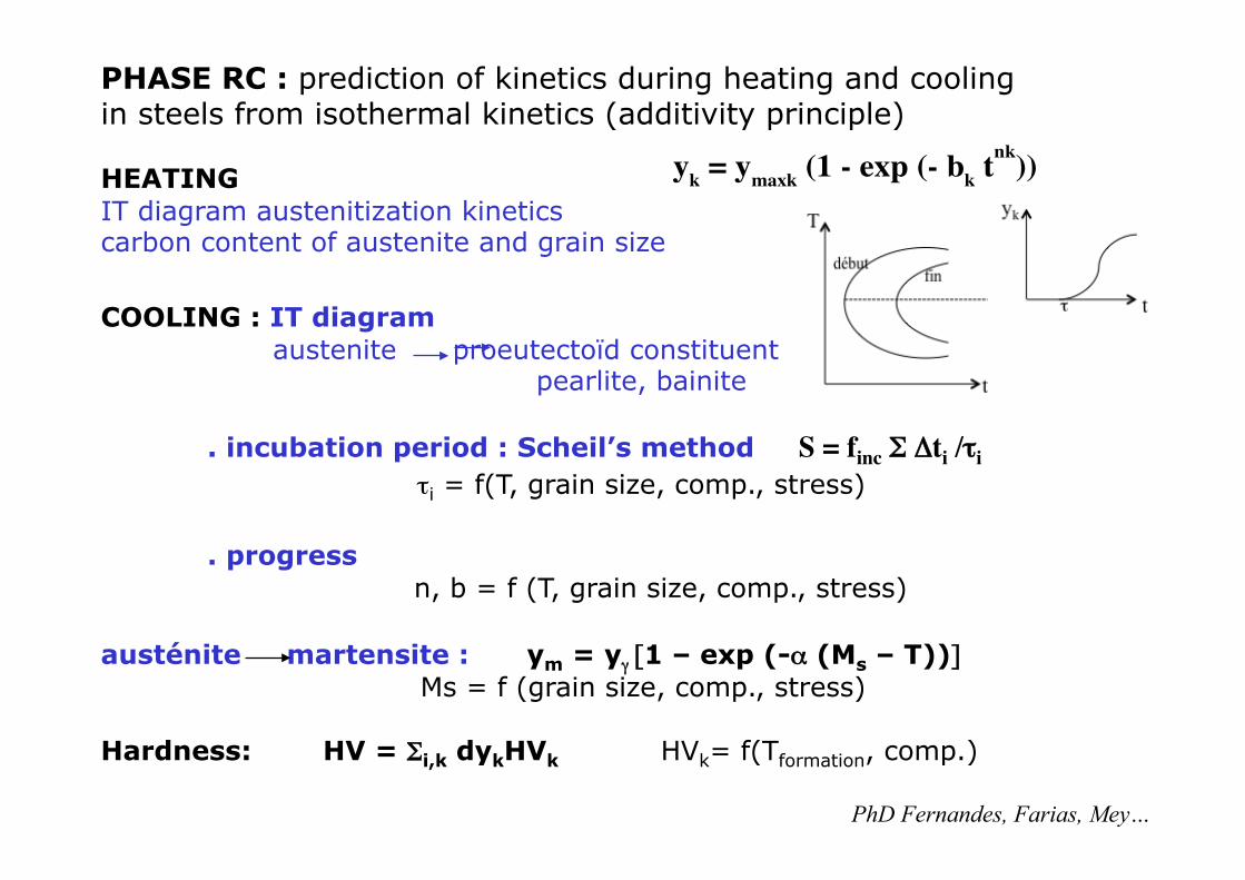
PHASE RC : prediction of kinetics during heating and cooling in steels from isothermal kinetics (additivity principle) HEATING IT diagram austenitization kinetics carbon content of austenite and grain size
yk = ymaxk (1 - exp (- bk tnk))
COOLING : IT diagram
austenite proeutectoïd constituent pearlite, bainite . incubation period : Scheil’s method S = finc Σ Δti /τi τi = f(T, grain size, comp., stress) . progress n, b = f (T, grain size, comp., stress)
austénite martensite : ym = yγ [1 – exp (-α (Ms – T))]
Ms = f (grain size, comp., stress) Hardness: HV = Σi,k dykHVk HVk= f(Tformation, comp.)
PhD Fernandes, Farias, Mey…
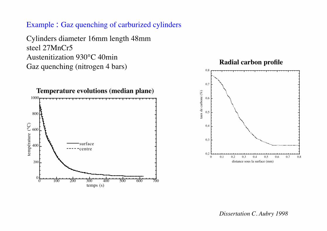
Example : Gaz quenching of carburized cylinders
Cylinders diameter 16mm length 48mm steel 27MnCr5 Austenitization 930°C 40min Gaz quenching (nitrogen 4 bars)
0,2
0,3
0,4
0,5
0,6
0,7
0,8
0 0,1 0,2 0,3 0,4 0,5 0,6 0,7 0,8distance sous la surface (mm)
taux
de
carb
one
(%)
0
200
400
600
800
1000
0 100 200 300 400 500 600 700
surfacecentre
tem
péra
ture
(°C
)
temps (s)
Temperature evolutions (median plane)
Radial carbon profile
Dissertation C. Aubry 1998
0
20
40
60
80
100
3 102
4 102
5 102
6 102
7 102
8 102
9 102
0 0,2 0,4 0,6 0,8 1
austéniteferritebainitemartensitetaux normé d'autorevenu
dureté
frac
tion
volu
miq
ue (%
)
dureté (HV
)
distance sous la surface (mm)
0 100 200 300 400 500
austéniteferritebainitemartensitetaux normé d'autorevenu
0
20
40
60
80
100
temps (s)
frac
tion
volu
miq
ue (
%)
0
20
40
60
80
100
0 100 200 300 400 500 600
austénitemartensitetaux normé d'autorevenu
frac
tion
volu
miq
ue (
%)
temps (s)
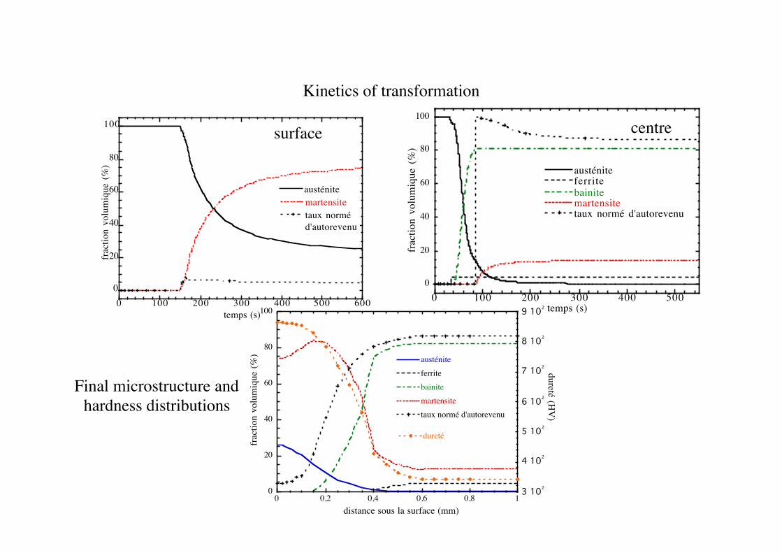
Final microstructure and hardness distributions
Kinetics of transformation
surface centre
14
0 1 2 3 4 5 60
0.2
0.4
0.6
0.8
1
Austénite.Perlite.Ferrite.Martensite.
Temps (s).
Frac
tion
volu
miq
ue.
80
200
400
600
800
1000
1200
0 1 2 3 4 5 6 7
0.0.5651.0651.542
Tem
péra
ture
(°C
).
Temps (s).
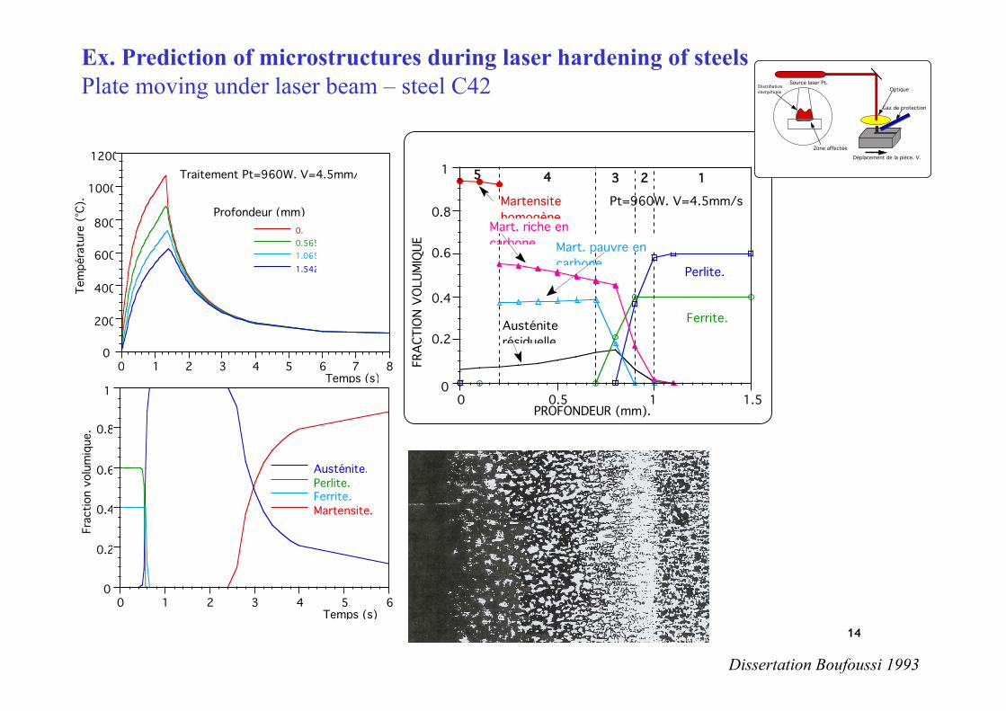
Profondeur (mm):
Traitement Pt=960W. V=4.5mm/s.
FRAC
TION
VOL
UMIQ
UEPROFONDEUR (mm).
0
0.2
0.4
0.6
0.8
1
0 0.5 1 1.5
1
Austénite résiduelle.
Martensite homogène.
Mart. riche en carbone. Mart. pauvre en
carbone.
Ferrite.
Perlite.
2345
Pt=960W. V=4.5mm/s
Dissertation Boufoussi 1993
Ex. Prediction of microstructures during laser hardening of steels Plate moving under laser beam – steel C42 Source laser Pt.
Zone affectéeDéplacement de la pièce. V.
Gaz de protection
OptiqueDistributionénergétique
15
Dure
té.
Profondeur (mm).
0
200
400
600
800
1000
0 0.5 1 1.5
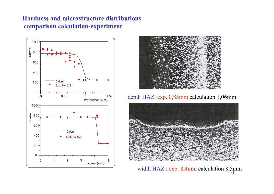
Calcul.Exp. Hv 0.3
0
200
400
600
800
1000
0 1 2 3 4 5
CalculExp. Hv 0.3.
Dure
té.
Largeur (mm).
Hardness and microstructure distributions comparison calculation-experiment
width HAZ : exp. 8,4mm calculation 8,5mm
depth HAZ: exp. 0,85mm calculation 1,06mm
Modelling of phase transformation kinetics (for the purpose of predicting internal stresses and deformations) • Global models (JMAK): most commonly used for steels - Modelling anisothermal kinetics from CCT diagrams - Modelling kinetics from IT diagrams (additivity principle)
can predict volume fractions of the phases for complex situations limitations : no morphological parameters of the microstructures
difficult to take into account prior plastic deformation effects • Nucleation, growth, coarsening models - precipitation in Al alloys D. Godard 1999 - tempering of martensite in steels Y. Wang 2006
volume fractions of the precipitates, size distributions matrix chemical composition
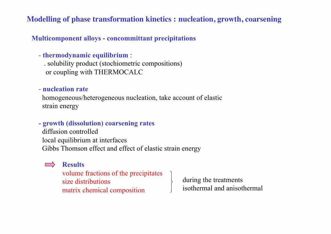
Multicomponent alloys - concommittant precipitations - thermodynamic equilibrium : . solubility product (stochiometric compositions) or coupling with THERMOCALC - nucleation rate homogeneous/heterogeneous nucleation, take account of elastic strain energy - growth (dissolution) coarsening rates diffusion controlled local equilibrium at interfaces Gibbs Thomson effect and effect of elastic strain energy
Results volume fractions of the precipitates size distributions matrix chemical composition
Modelling of phase transformation kinetics : nucleation, growth, coarsening
during the treatments isothermal and anisothermal
0
0,2
0,4
0,6
0,8
1
0 100 200 300 400 500 600 700
carbure !, cal.cémentite cal.
carbure !, exp.cémentite, exp.
Température (°C)
0
0,05
0,1
0,15
0
100
200
300
400
500
600
0 20 40 60 80 100
Carbure !Cémentite
Température
Temps (s)
0
0,005
0,01
0,015
0,02
0,025
0,03
0,035
0,04
1 10 100 1000 104 105
C, Cal.Cr, Cal.Mn,Cal.Cr, Exp.Mn,Exp.
Composition (atomique)
Temps (s)
0
2 10-9
4 10-9
6 10-9
8 10-9
1 10-8
0
100
200
300
400
500
600
0 20 40 60 80 100
Rayon critique, Cal.Rayon moyen Cal.
Température
Temps (s) 0
2 10-8
4 10-8
6 10-8
8 10-8
1 10-7
1 10 100 1000 104 105
Rayon critique, Cal.Rayon moyen, Cal.Rayon Exp.
Temps (s)
Cementite
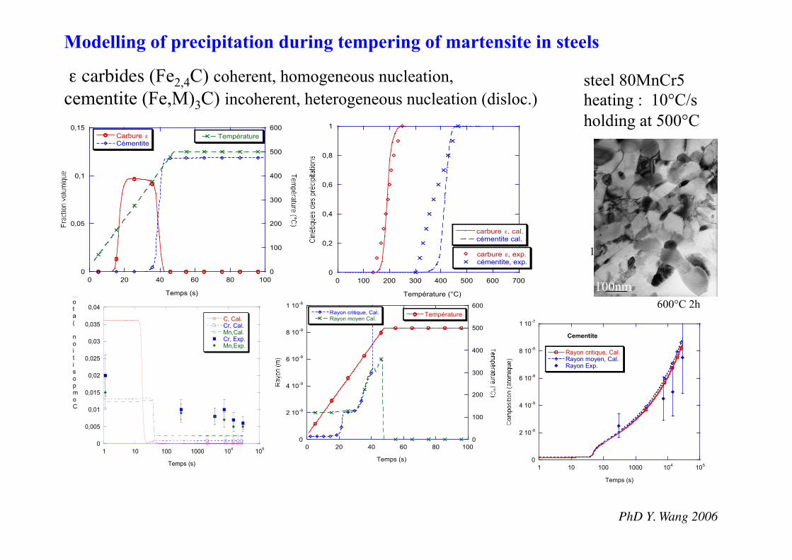
ε carbides (Fe2,4C) coherent, homogeneous nucleation, cementite (Fe,M)3C) incoherent, heterogeneous nucleation (disloc.)
PhD Y. Wang 2006
Modelling of precipitation during tempering of martensite in steels
steel 80MnCr5 heating : 10°C/s holding at 500°C
100nm
100nm 600°C 2h
Fluid – thermal – metallurgical – mechanical couplings in heat treatment
FLUID FLOW material
DEFORMATION
Température
Température de transformation
Austénitization
Transformation bainitique
Temps Contrainte
0
200
400
600
800
1000
1200
0 200 400 600 800 1000 1200 1400
TempératureContrainte
DéformationTem
péra
ture
(°C
) / c
ontra
inte
(M
Pa)
Temps (s)
εpt
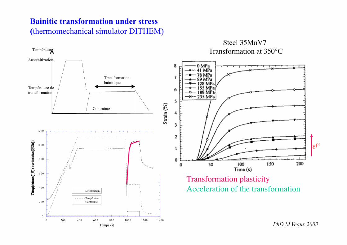
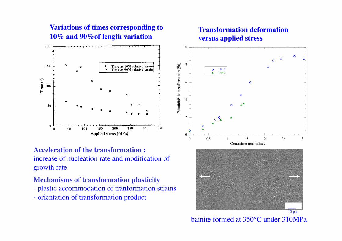
Transformation plasticity Acceleration of the transformation
Bainitic transformation under stress (thermomechanical simulator DITHEM)
Steel 35MnV7 Transformation at 350°C
PhD M Veaux 2003
0
2
4
6
8
10
0 0,5 1 1,5 2 2,5 3
350°C450°C
Plas
ticité
de
trans
form
atio
n (%
)
Contrainte normalisée
____ 10 µm
bainite formed at 350°C under 310MPa
Mechanisms of transformation plasticity - plastic accommodation of tranformation strains - orientation of transformation product
Transformation deformation versus applied stress
Variations of times corresponding to 10% and 90%of length variation
Acceleration of the transformation : increase of nucleation rate and modification of growth rate
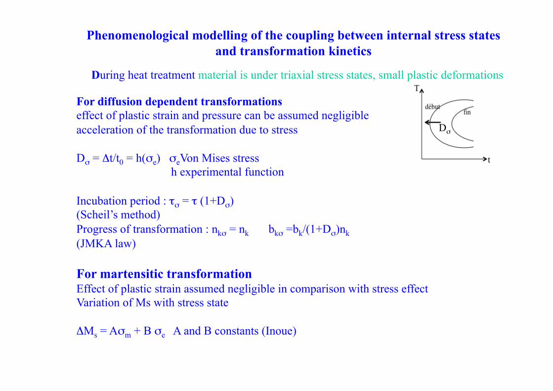
Phenomenological modelling of the coupling between internal stress states and transformation kinetics
During heat treatment material is under triaxial stress states, small plastic deformations
For diffusion dependent transformations effect of plastic strain and pressure can be assumed negligible acceleration of the transformation due to stress Dσ = Δt/t0 = h(σe) σeVon Mises stress h experimental function Incubation period : τσ = τ (1+Dσ) (Scheil’s method) Progress of transformation : nkσ = nk bkσ =bk/(1+Dσ)nk (JMKA law)
For martensitic transformation Effect of plastic strain assumed negligible in comparison with stress effect Variation of Ms with stress state ΔMs = Aσm + B σe A and B constants (Inoue)
Dσ
-150
-100
-50
0
50
100
150
0 50 100 150 200 250 300 350
Con
train
te (M
Pa)
Temps (s)
-200
-150
-100
-50
0
50
100
0 50 100 150 200 250 300 350
Con
train
te (M
Pa)
Temps (s)
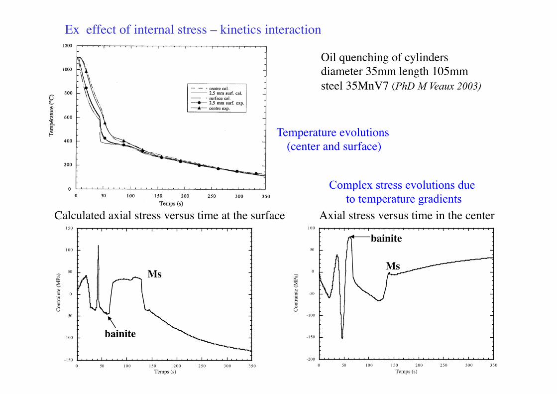
Ex effect of internal stress – kinetics interaction
Temperature evolutions (center and surface)
Calculated axial stress versus time at the surface Axial stress versus time in the center
Oil quenching of cylinders diameter 35mm length 105mm steel 35MnV7 (PhD M Veaux 2003)
bainite
bainite
Ms Ms
Complex stress evolutions due to temperature gradients
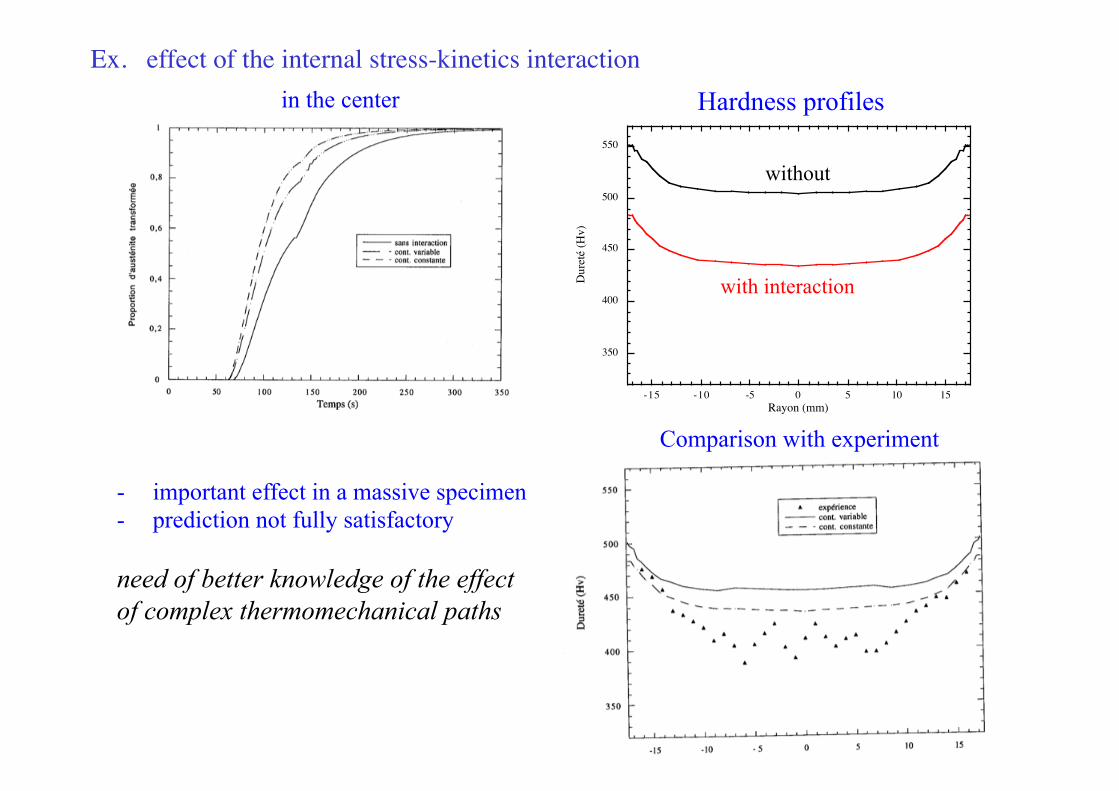
Ex. effect of the internal stress-kinetics interaction
350
400
450
500
550
-15 -10 -5 0 5 10 15
Dur
eté
(Hv)
Rayon (mm)
in the center Hardness profiles
with interaction
Comparison with experiment
- important effect in a massive specimen - prediction not fully satisfactory need of better knowledge of the effect of complex thermomechanical paths
without
Fluid – thermal – metallurgical – mechanical couplings in heat treatment
FLUID FLOW material
DEFORMATION
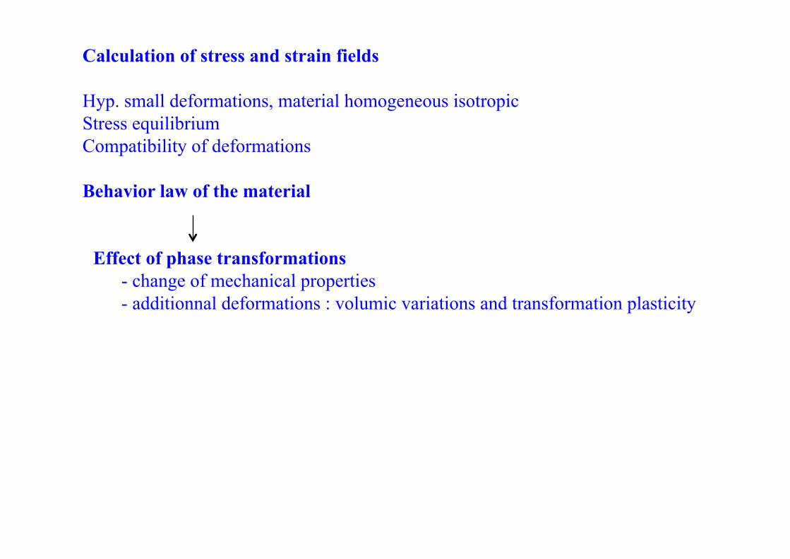
Calculation of stress and strain fields Hyp. small deformations, material homogeneous isotropic Stress equilibrium Compatibility of deformations Behavior law of the material
Effect of phase transformations - change of mechanical properties - additionnal deformations : volumic variations and transformation plasticity
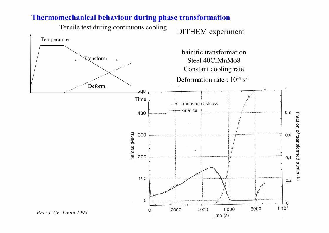
Tensile test during continuous cooling
Time
Temp. .
Transform.
Deform.
DITHEM experiment
Thermomechanical behaviour during phase transformation
bainitic transformation Steel 40CrMnMo8
Constant cooling rate Deformation rate : 10-4 s-1
Temperature
PhD J. Ch. Louin 1998
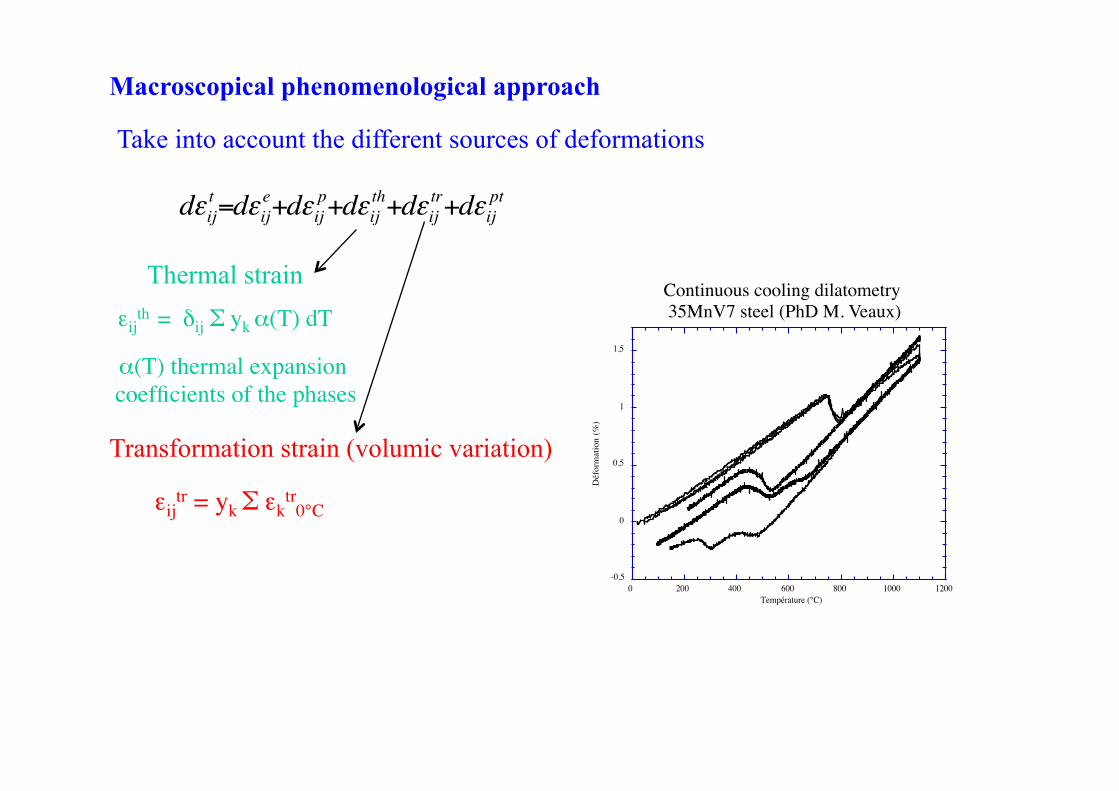
Take into account the different sources of deformations d!ij
t=d!ije+d!ij
p+d!ijth+d!ij
tr+d!ijpt
-0,5
0
0,5
1
1,5
0 200 400 600 800 1000 1200D
éfor
mat
ion
(%)
Température (°C)
εijth = δij Σ yk α(T) dT
α(T) thermal expansion coefficients of the phases
εijtr = yk Σ εk
tr0°C
Continuous cooling dilatometry 35MnV7 steel (PhD M. Veaux)
Macroscopical phenomenological approach
Thermal strain
Transformation strain (volumic variation)
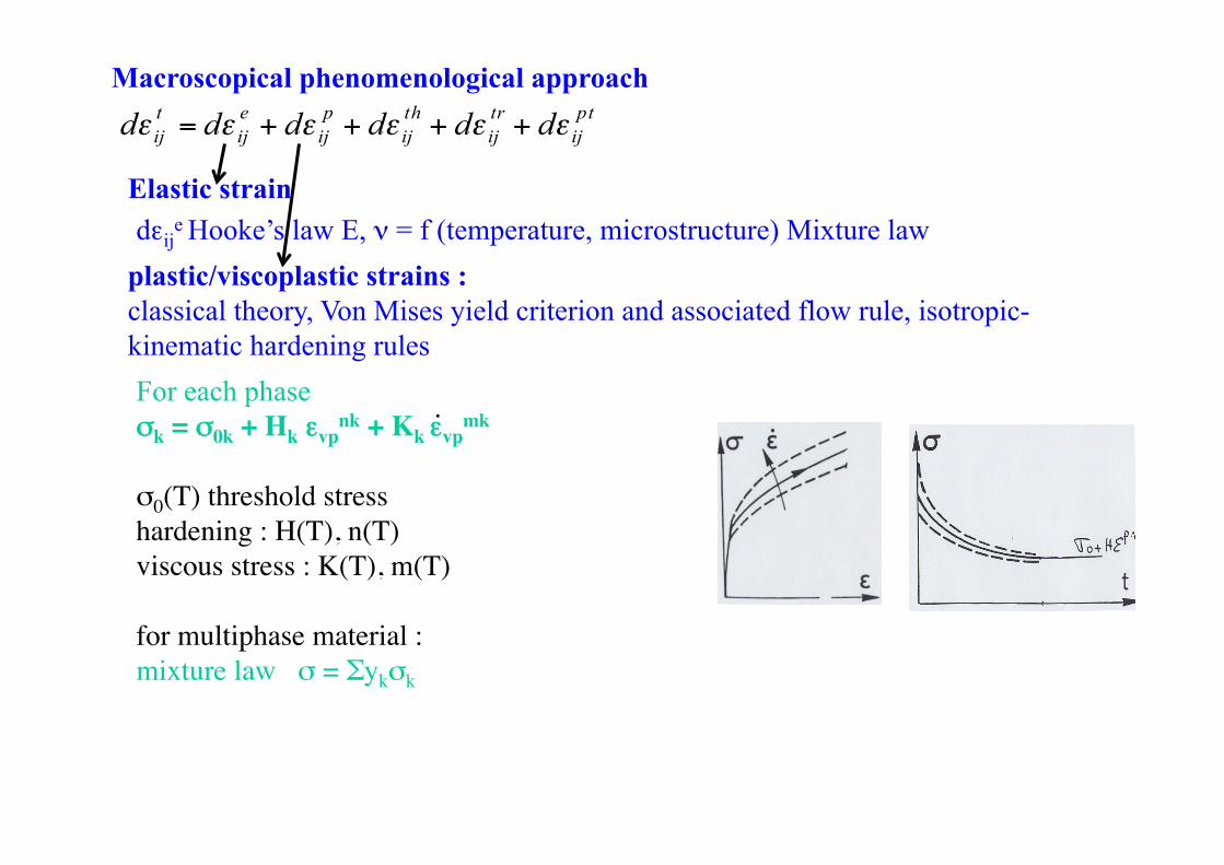
Elastic strain dεij
e Hooke’s law E, ν = f (temperature, microstructure) Mixture law plastic/viscoplastic strains : classical theory, Von Mises yield criterion and associated flow rule, isotropic- kinematic hardening rules
Macroscopical phenomenological approach
For each phase σk = σ0k + Hk εvp
nk + Kk εvpmk
σ0(T) threshold stress hardening : H(T), n(T) viscous stress : K(T), m(T) for multiphase material : mixture law σ = Σykσk
.
d! ijt = d! ij
e + d! ijp + d! ij
th + d! ijtr + d! ij
pt
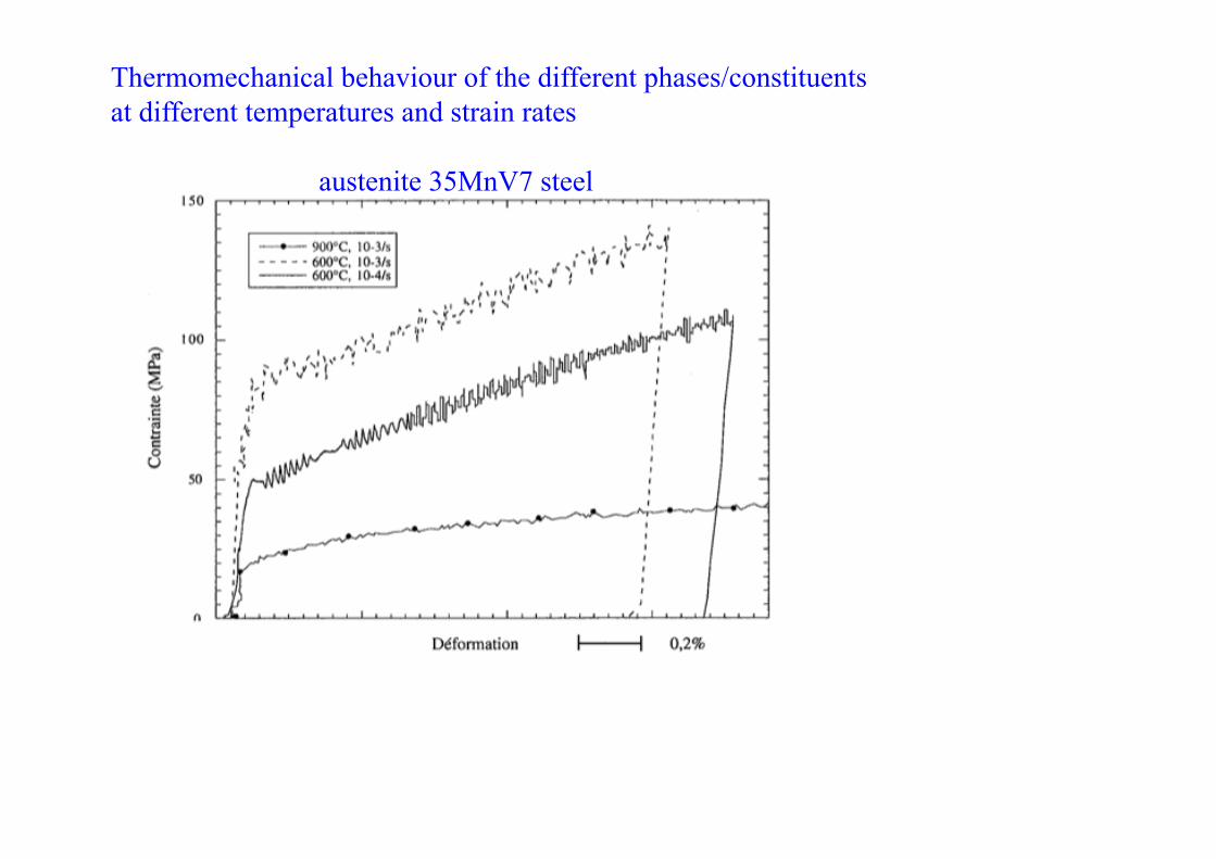
Thermomechanical behaviour of the different phases/constituents at different temperatures and strain rates
austenite 35MnV7 steel
0
200
400
600
800
1000
1200
0
0 , 5
1
1 , 5
2
0 500 1000 1500 2000
TempératureContrainte
Déformation
Tem
péra
ture
(°C
)/Con
train
te (M
Pa)
Déform
ation (%)
Temps (s)
Transform
Time
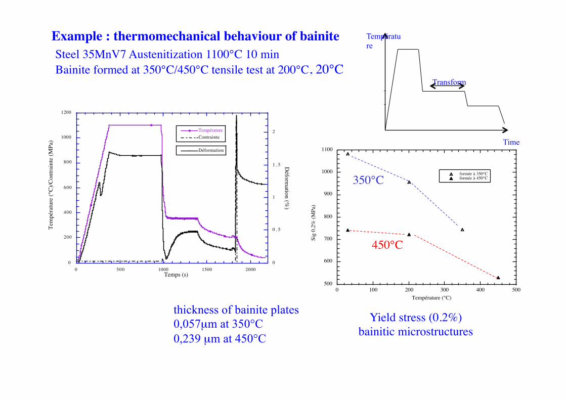
Température Example : thermomechanical behaviour of bainite
Steel 35MnV7 Austenitization 1100°C 10 min Bainite formed at 350°C/450°C tensile test at 200°C, 20°C
500
600
700
800
900
1000
1100
0 100 200 300 400 500
formée à 350°Cformée à 450°C
Sig
0,2%
(MPa
)
Température (°C)
350°C
450°C
Yield stress (0.2%) bainitic microstructures
thickness of bainite plates 0,057µm at 350°C 0,239 µm at 450°C
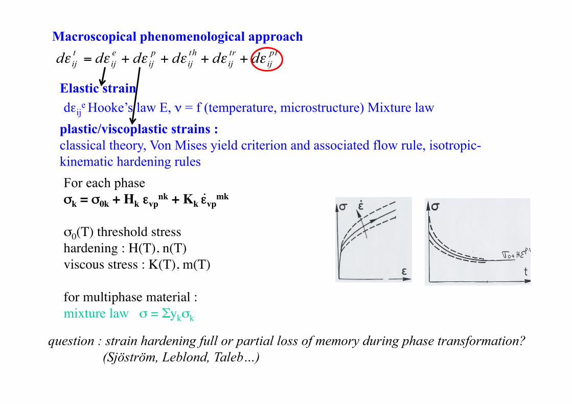
Elastic strain dεij
e Hooke’s law E, ν = f (temperature, microstructure) Mixture law plastic/viscoplastic strains : classical theory, Von Mises yield criterion and associated flow rule, isotropic- kinematic hardening rules
Macroscopical phenomenological approach
For each phase σk = σ0k + Hk εvp
nk + Kk εvpmk
σ0(T) threshold stress hardening : H(T), n(T) viscous stress : K(T), m(T) for multiphase material : mixture law σ = Σykσk
.
question : strain hardening full or partial loss of memory during phase transformation? (Sjöström, Leblond, Taleb…)
d! ijt = d! ij
e + d! ijp + d! ij
th + d! ijtr + d! ij
pt
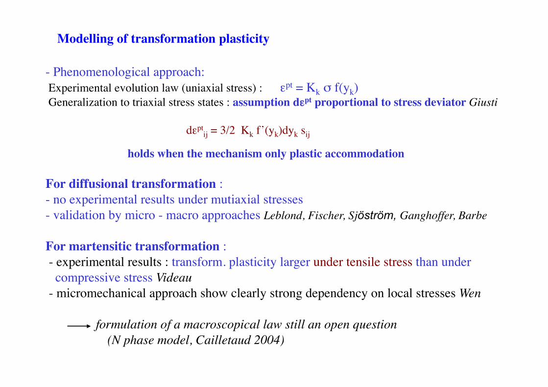
Modelling of transformation plasticity
- Phenomenological approach: Experimental evolution law (uniaxial stress) : εpt = Kk σ f(yk) Generalization to triaxial stress states : assumption dεpt proportional to stress deviator Giusti
dεpt
ij = 3/2 Kk f’(yk)dyk sij
holds when the mechanism only plastic accommodation For diffusional transformation : - no experimental results under mutiaxial stresses - validation by micro - macro approaches Leblond, Fischer, Sjöström, Ganghoffer, Barbe
For martensitic transformation : - experimental results : transform. plasticity larger under tensile stress than under compressive stress Videau - micromechanical approach show clearly strong dependency on local stresses Wen
formulation of a macroscopical law still an open question (N phase model, Cailletaud 2004)
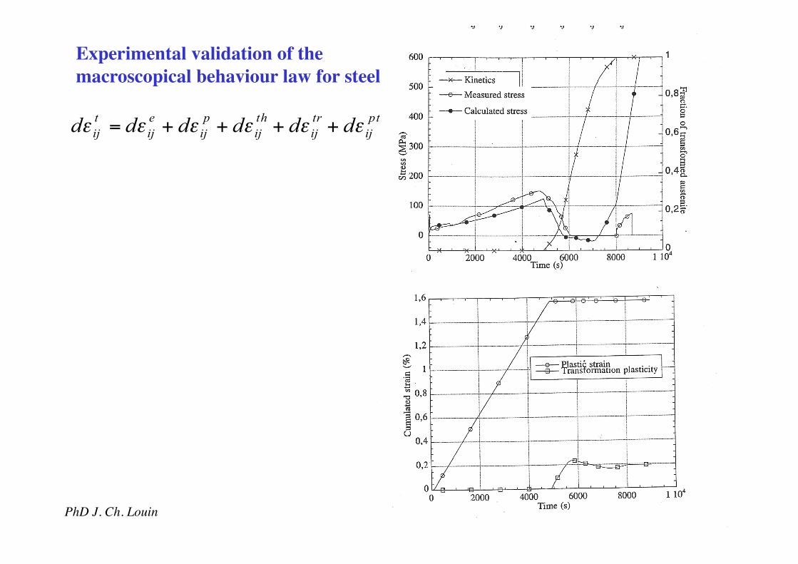
Experimental validation of the macroscopical behaviour law for steel
d! ijt = d! ij
e + d! ijp + d! ij
th + d! ijtr + d! ij
pt
PhD J. Ch. Louin
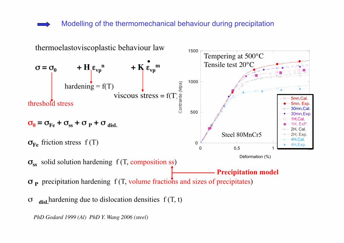
thermoelastoviscoplastic behaviour law σ = σ0 + H εvp
n + K εvpm
hardening = f(T) viscous stress = f(T)
threshold stress σ0 = σFe + σss + σ P + σ disl. σFe friction stress f (T) σss solid solution hardening f (T, composition ss) σ P precipitation hardening f (T, volume fractions and sizes of precipitates) σ disl.hardening due to dislocation densities f (T, t)
0
500
1000
1500
0 0,5 1 1,5
5mn,Cal.5mn, Exp.30mn,Cal.30mn,Exp.1H,Cal.1H, ExP.2H, Cal.2H, Exp.4H,Cal.4H,Exp.
Déformation (%)
Steel 80MnCr5
Modelling of the thermomechanical behaviour during precipitation
Precipitation model
PhD Y. Wang 2006 (steel)
Tempering at 500°C Tensile test 20°C
PhD Godard 1999 (Al)
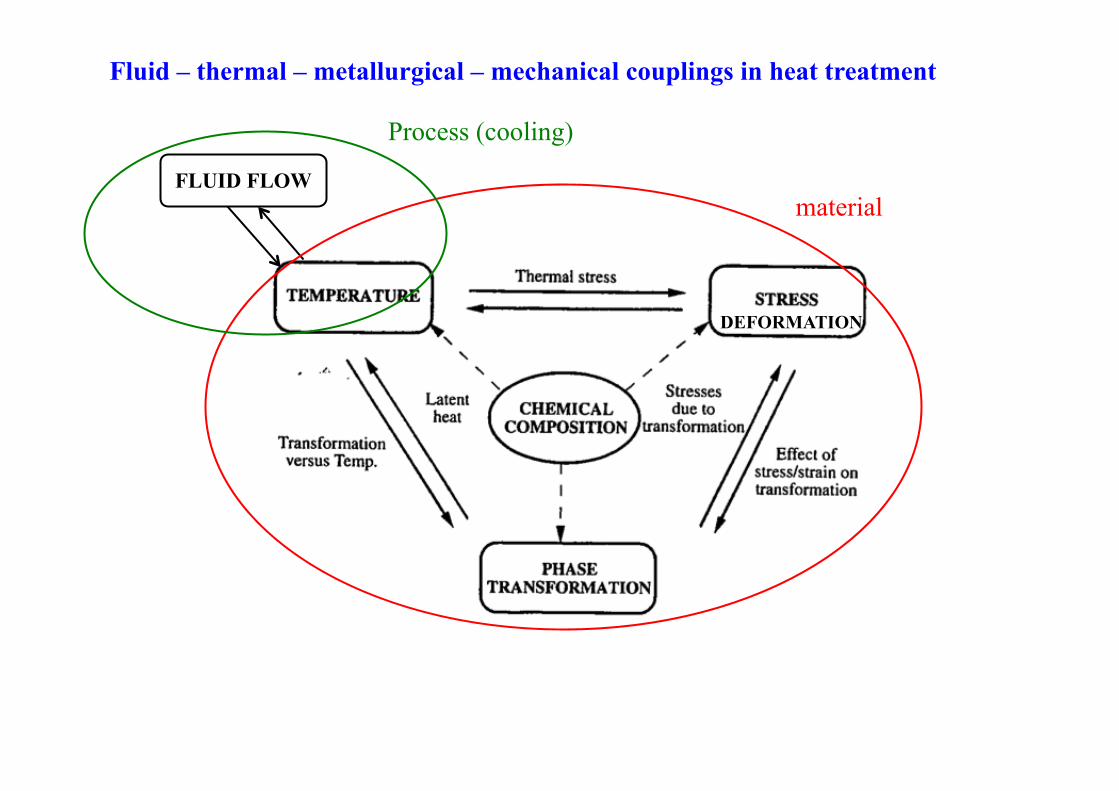
Fluid – thermal – metallurgical – mechanical couplings in heat treatment
FLUID FLOW material
Process (cooling)
DEFORMATION
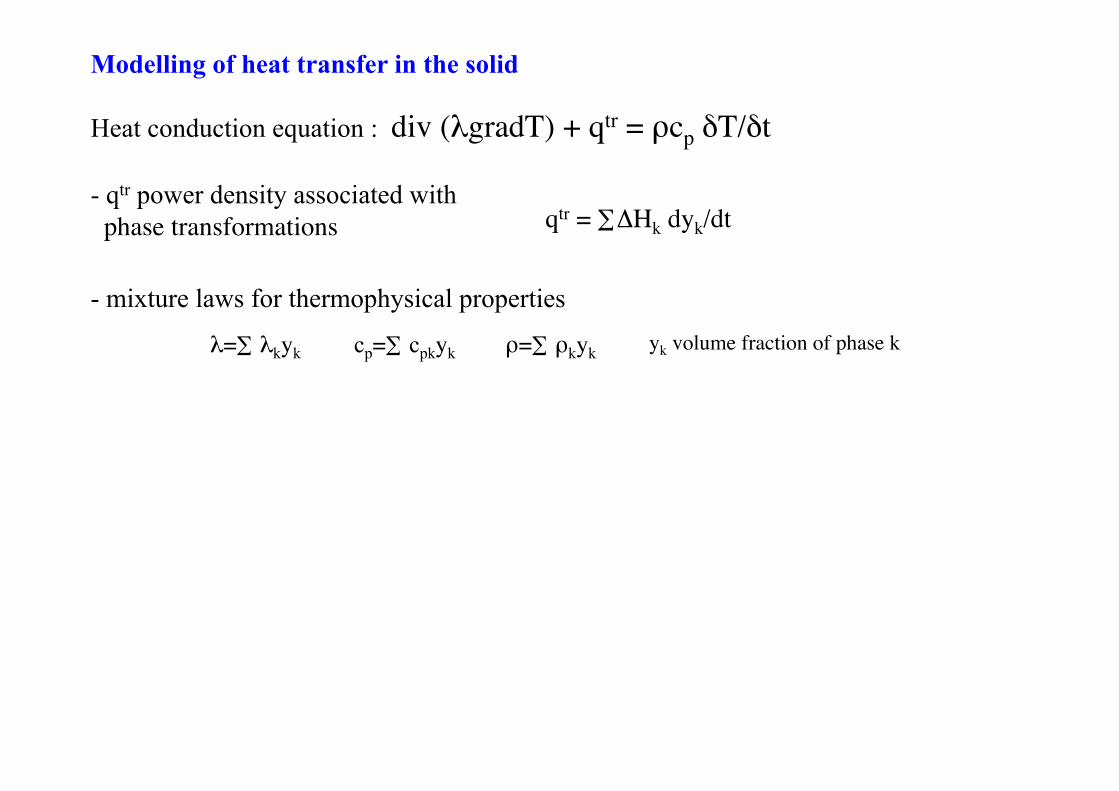
Heat conduction equation : div (λgradT) + qtr = ρcp δT/δt
- qtr power density associated with phase transformations
Modelling of heat transfer in the solid
- mixture laws for thermophysical properties
λ=∑ λkyk
qtr = ∑ΔHk dyk/dt
yk volume fraction of phase k cp=∑ cpkyk ρ=∑ ρkyk
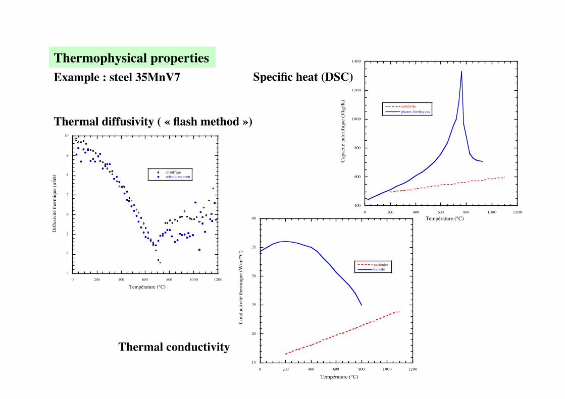
Example : steel 35MnV7 Thermophysical properties
400
600
800
1000
1200
1400
0 200 400 600 800 1000 1200
austénite phases ferritiques
Cap
acité
cal
orifi
que
(J/k
g/K
)
Température (°C)
3
4
5
6
7
8
9
10
0 200 400 600 800 1000 1200
chauffagerefroidissement
Diff
usiv
ité th
erm
ique
(mm2/s
)
Température (°C)
15
20
25
30
35
40
0 200 400 600 800 1000 1200
austénite bainite
Con
duct
ivité
ther
miq
ue (W
/m/°
C)
Température (°C)
Thermal diffusivity ( « flash method »)
Specific heat (DSC)
Thermal conductivity
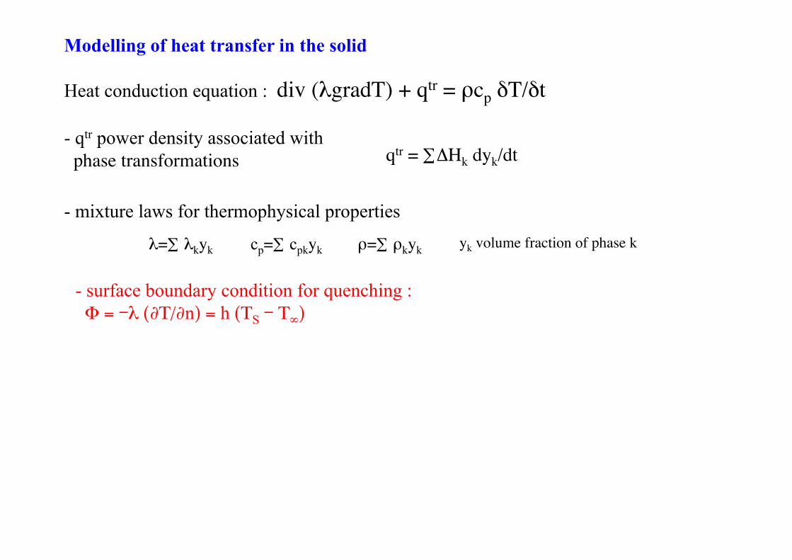
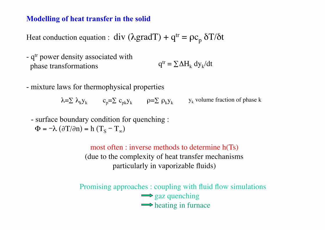
Heat conduction equation : div (λgradT) + qtr = ρcp δT/δt
- surface boundary condition for quenching : Φ = -λ (∂Τ/∂n) = h (ΤS - Τ∞)
- qtr power density associated with phase transformations
Modelling of heat transfer in the solid
- mixture laws for thermophysical properties
λ=∑ λkyk
qtr = ∑ΔHk dyk/dt
yk volume fraction of phase k cp=∑ cpkyk ρ=∑ ρkyk
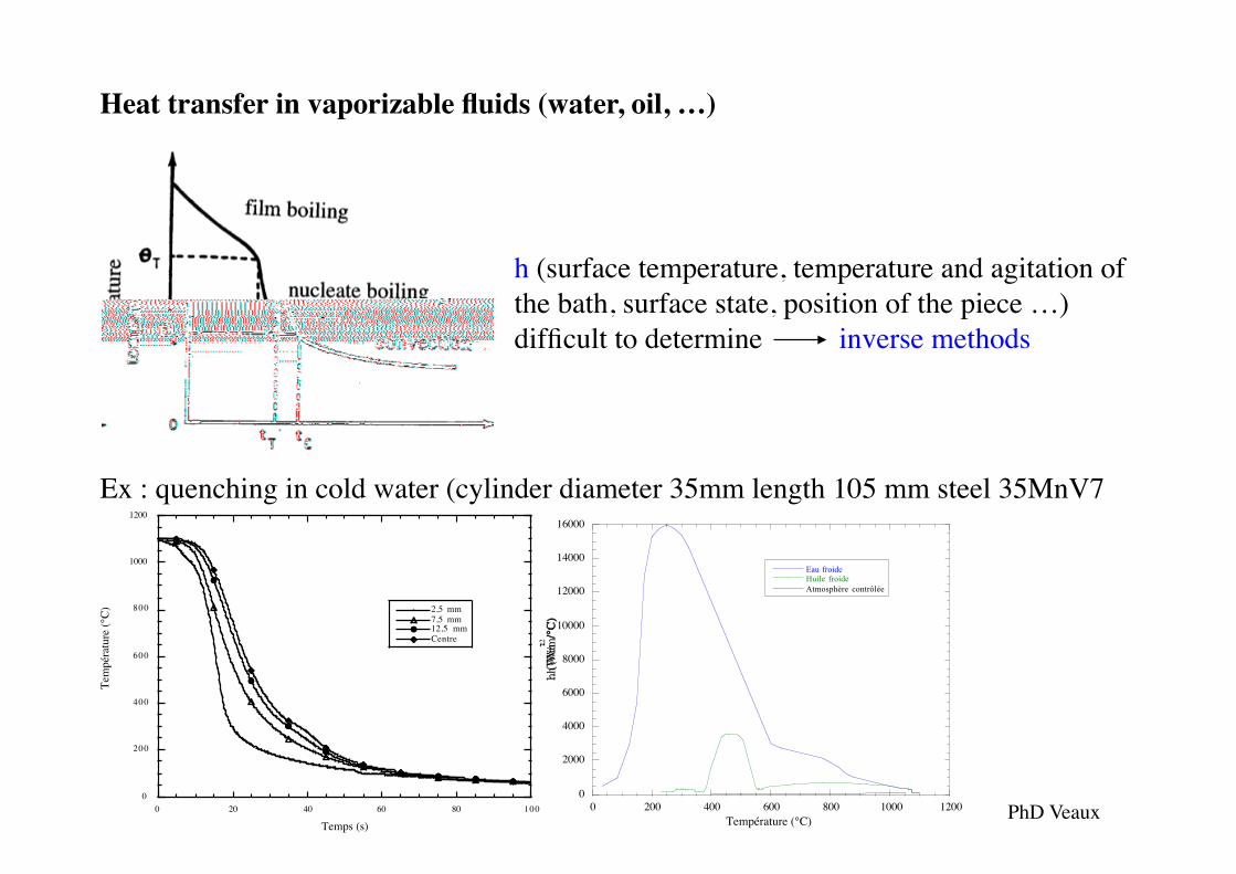
Heat transfer in vaporizable fluids (water, oil, …)
h (surface temperature, temperature and agitation of the bath, surface state, position of the piece …) difficult to determine inverse methods
0
200
400
600
800
1000
1200
0 20 40 60 80 100
2,5 mm7,5 mm12,5 mmCentre
Tem
péra
ture
(°C)
Temps (s)
0
2000
4000
6000
8000
10000
12000
14000
16000
0 200 400 600 800 1000 1200
Eau froideHuile froideAtmosphère contrôlée
h (W
/m2 /°C
)
Température (°C)
Ex : quenching in cold water (cylinder diameter 35mm length 105 mm steel 35MnV7
PhD Veaux
Heat conduction equation : div (λgradT) + qtr = ρcp δT/δt
- surface boundary condition for quenching : Φ = -λ (∂Τ/∂n) = h (ΤS - Τ∞)
- qtr power density associated with phase transformations
Modelling of heat transfer in the solid
- mixture laws for thermophysical properties
λ=∑ λkyk
qtr = ∑ΔHk dyk/dt
yk volume fraction of phase k cp=∑ cpkyk ρ=∑ ρkyk
most often : inverse methods to determine h(Ts) (due to the complexity of heat transfer mechanisms
particularly in vaporizable fluids)
Promising approaches : coupling with fluid flow simulations gaz quenching heating in furnace
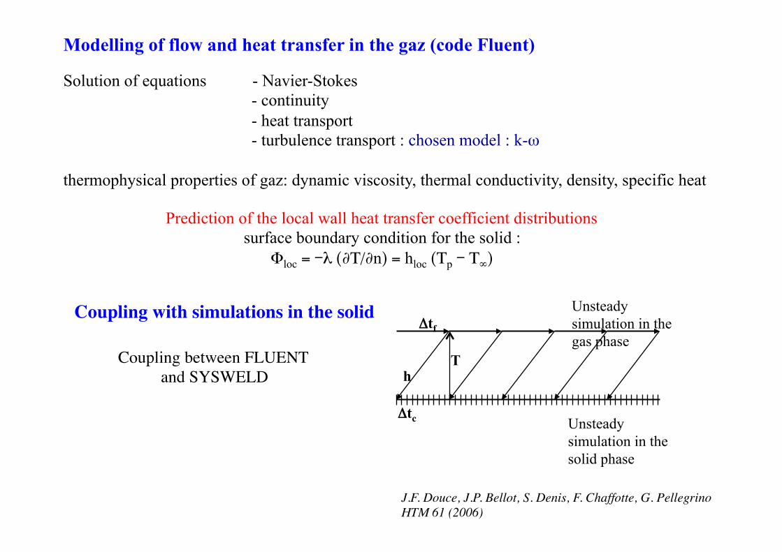
Modelling of flow and heat transfer in the gaz (code Fluent) Solution of equations - Navier-Stokes
- continuity - heat transport - turbulence transport : chosen model : k-ω
thermophysical properties of gaz: dynamic viscosity, thermal conductivity, density, specific heat
Prediction of the local wall heat transfer coefficient distributions surface boundary condition for the solid :
Φloc = -λ (∂Τ/∂n) = hloc (Τp - Τ∞)
h T
Δtf
Δtc Unsteady simulation in the solid phase
Unsteady simulation in the gas phase
Coupling between FLUENT and SYSWELD
Coupling with simulations in the solid
J.F. Douce, J.P. Bellot, S. Denis, F. Chaffotte, G. Pellegrino HTM 61 (2006)
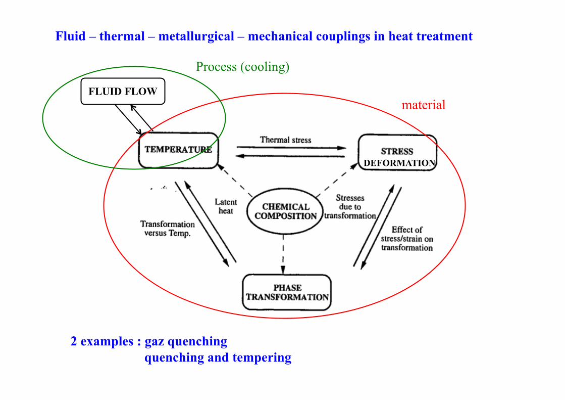
Fluid – thermal – metallurgical – mechanical couplings in heat treatment
FLUID FLOW material
Process (cooling)
DEFORMATION
2 examples : gaz quenching quenching and tempering
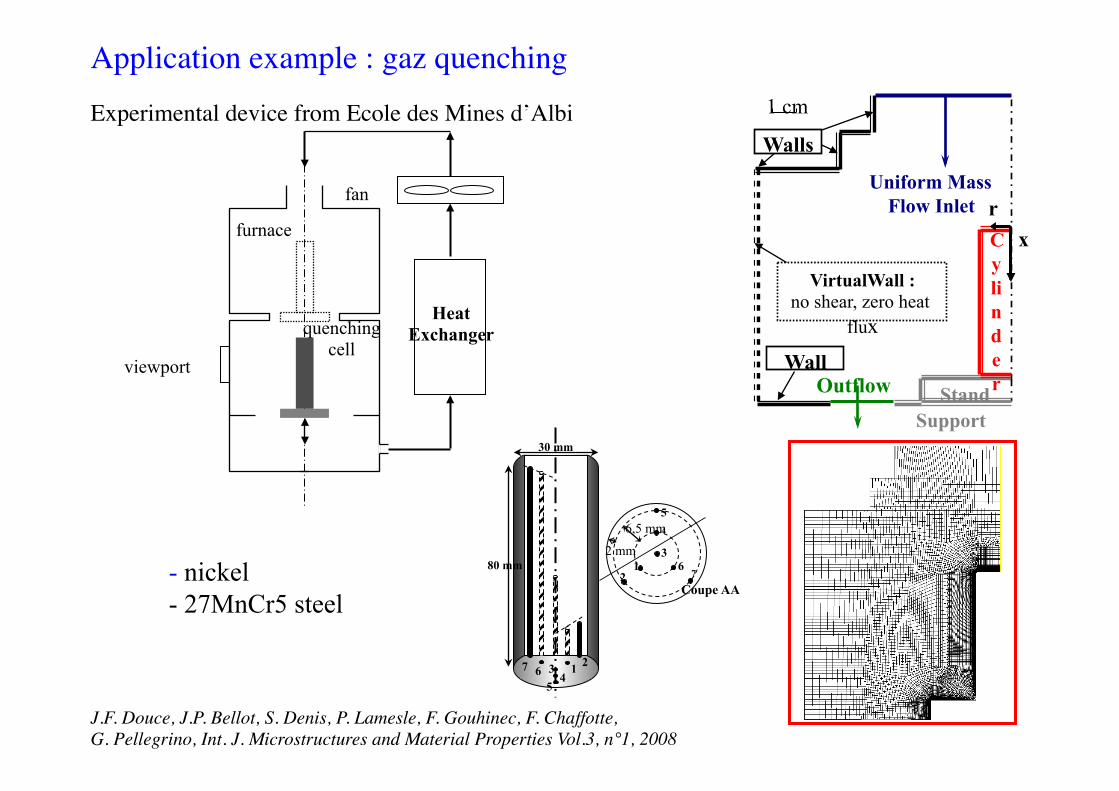
Cylinder Stand
Uniform Mass Flow Inlet
Outflow Wall
VirtualWall : no shear, zero heat
flux
Support
Walls 1 cm
r x
Heat Exchanger
fan
viewport
furnace
quenching cell
Application example : gaz quenching Experimental device from Ecole des Mines d’Albi
30 mm
80 mm 12
67
3
4
5
67
54
3 21
2 mm 6,5 mm
Coupe AA
J.F. Douce, J.P. Bellot, S. Denis, P. Lamesle, F. Gouhinec, F. Chaffotte, G. Pellegrino, Int. J. Microstructures and Material Properties Vol.3, n°1, 2008
- nickel - 27MnCr5 steel
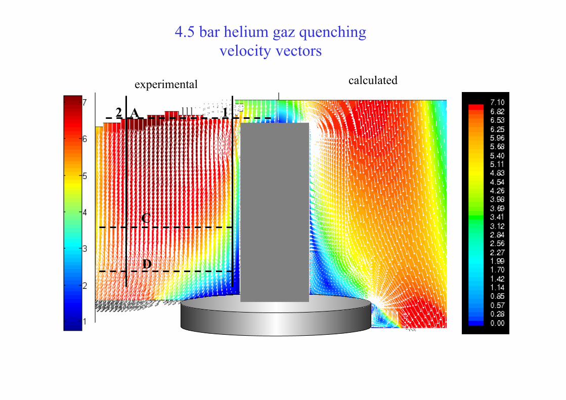
A
C
D
1 2
4.5 bar helium gaz quenching velocity vectors
experimental calculated
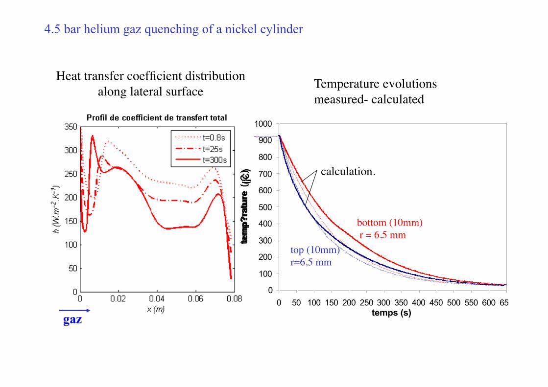
Heat transfer coefficient distribution along lateral surface
4.5 bar helium gaz quenching of a nickel cylinder
0
100
200
300
400
500
600
700
800
900
1000
0 50 100 150 200 250 300 350 400 450 500 550 600 650temps (s)
tem
p?ra
ture
(¡C
)
10 mm milieu70 mm milieu10 mm milieu (mod?lisation )70 mm milieu (mod?lisation )
Temperature evolutions measured- calculated
bottom
top (10mm) r=6,5 mm
bottom (10mm) r = 6,5 mm
calculation.
gaz
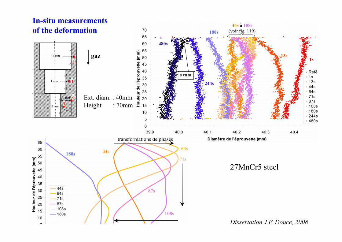
In-situ measurements of the deformation
Ext. diam. : 40mm Height : 70mm
gaz
27MnCr5 steel
Dissertation J.F. Douce, 2008
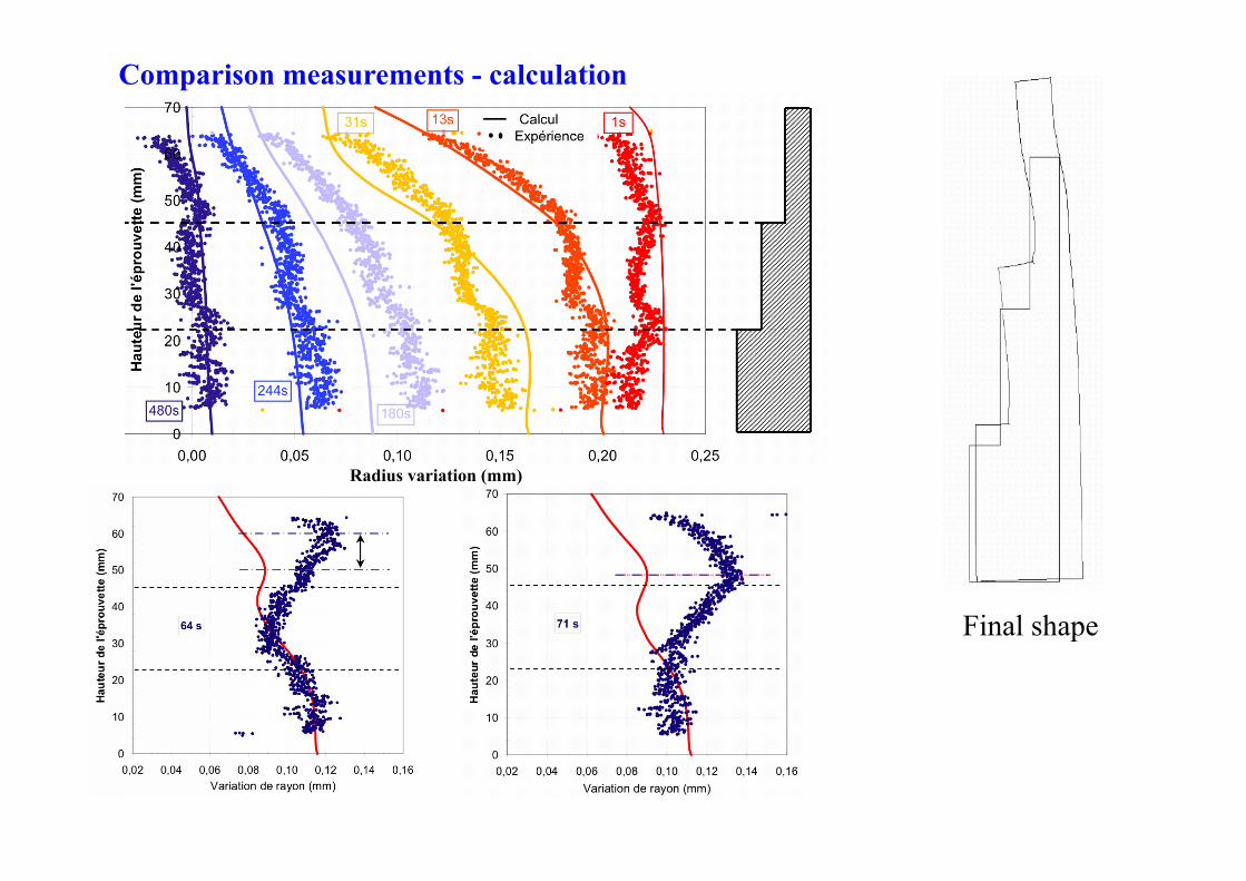
Comparison measurements - calculation
Radius variation (mm)
Final shape
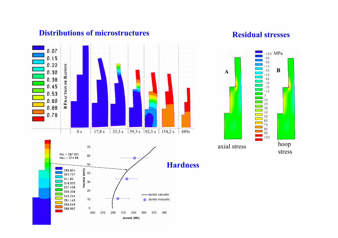
Distributions of microstructures Residual stresses
Hardness
axial stress hoop stress
0
200
400
600
800
1000
0 50 100 150 200
CentreSurface
Temps (s)
-1200
-800
-400
0
400
0 50 100 150 200
!z, Centre
!z, Surface
Temps (s)
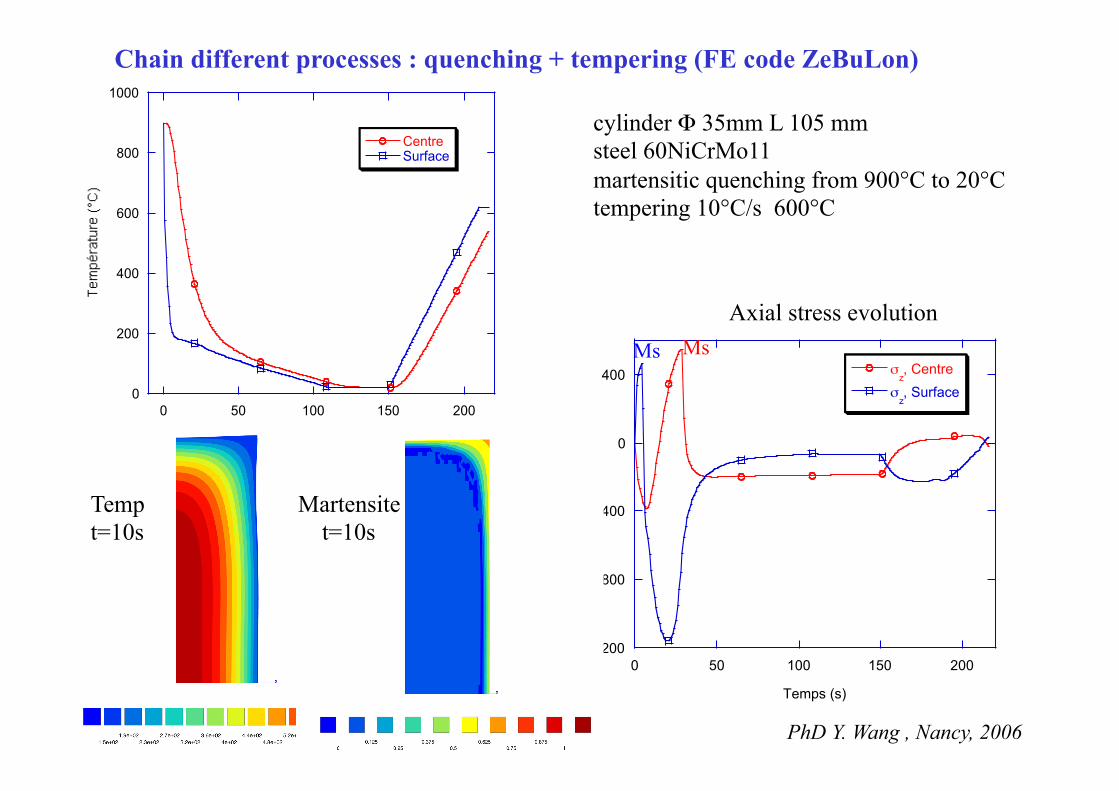
Chain different processes : quenching + tempering (FE code ZeBuLon)
cylinder Φ 35mm L 105 mm steel 60NiCrMo11 martensitic quenching from 900°C to 20°C tempering 10°C/s 600°C
Axial stress evolution
Temp t=10s
Martensite t=10s
PhD Y. Wang , Nancy, 2006
Ms Ms
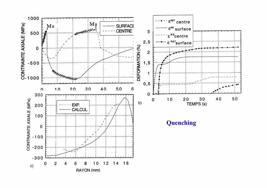
Quenching
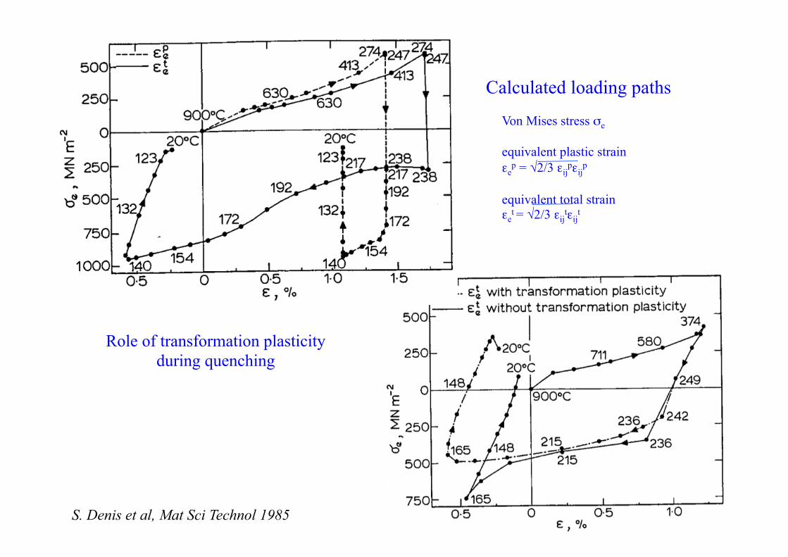
Calculated loading paths
Von Mises stress σe equivalent plastic strain εe
p = √2/3 εijpεij
p
equivalent total strain εe
t = √2/3 εijtεij
t
S. Denis et al, Mat Sci Technol 1985
Role of transformation plasticity during quenching
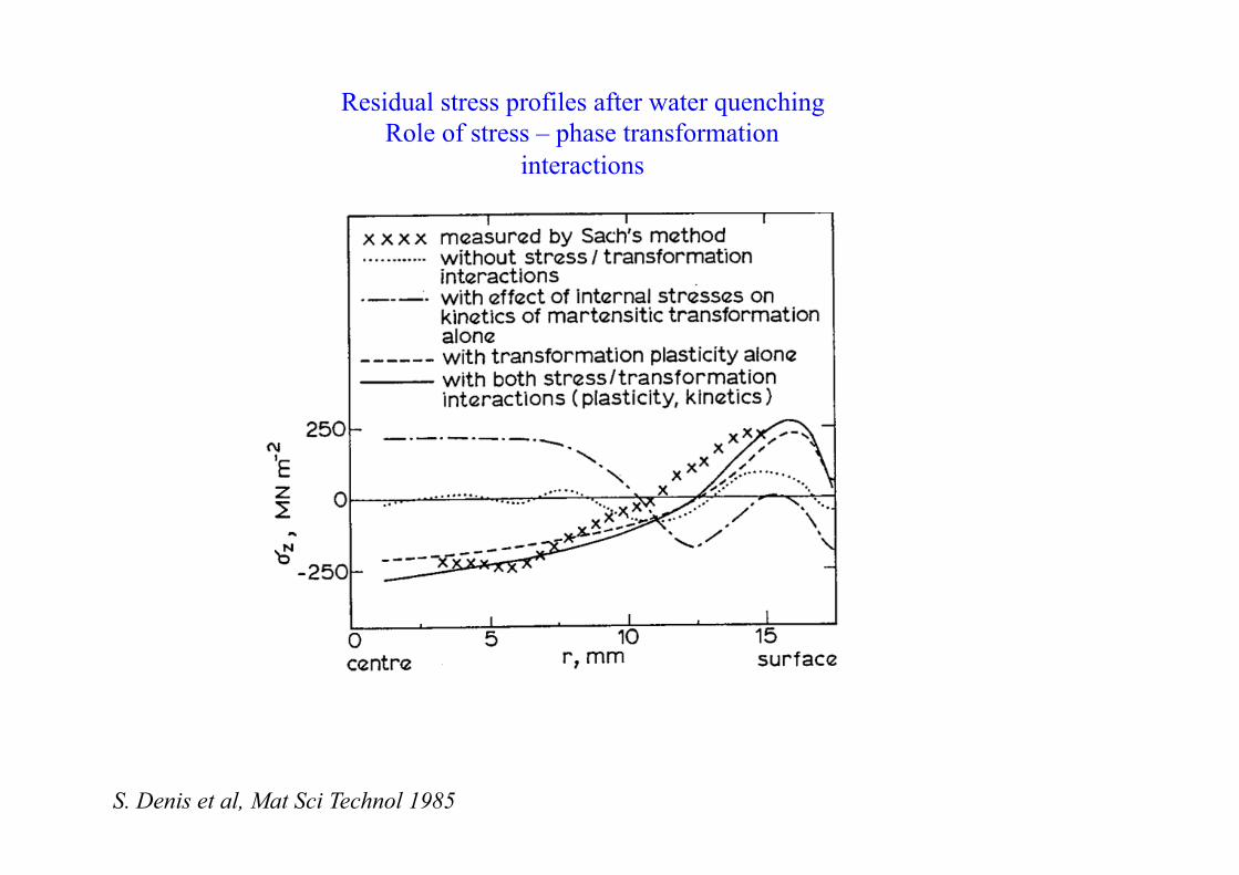
Residual stress profiles after water quenching Role of stress – phase transformation
interactions
S. Denis et al, Mat Sci Technol 1985
-400
-300
-200
-100
0
100
200
0
100
200
300
400
500
600
150 160 170 180 190 200 210 220
!z, centre, avec trans. de phase
!z, surface, avec trans. de phase
!z, centre, sans trans. de phase
!z, surface, sans trans. de phase
!0, centre
!0, surface
Temps (s)
0
200
400
600
800
1000
0
100
200
300
400
500
600
700
800
150 160 170 180 190 200 210 220
!0
!ss
!ps
!ds
!fsTempérature
Temps (s)
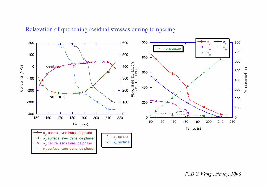
Relaxation of quenching residual stresses during tempering
surface
centre
PhD Y. Wang , Nancy, 2006
-300
-200
-100
0
100
200
0 0.005 0.01 0.015 0.02
150s170s190s210s215s
Rayon (m)
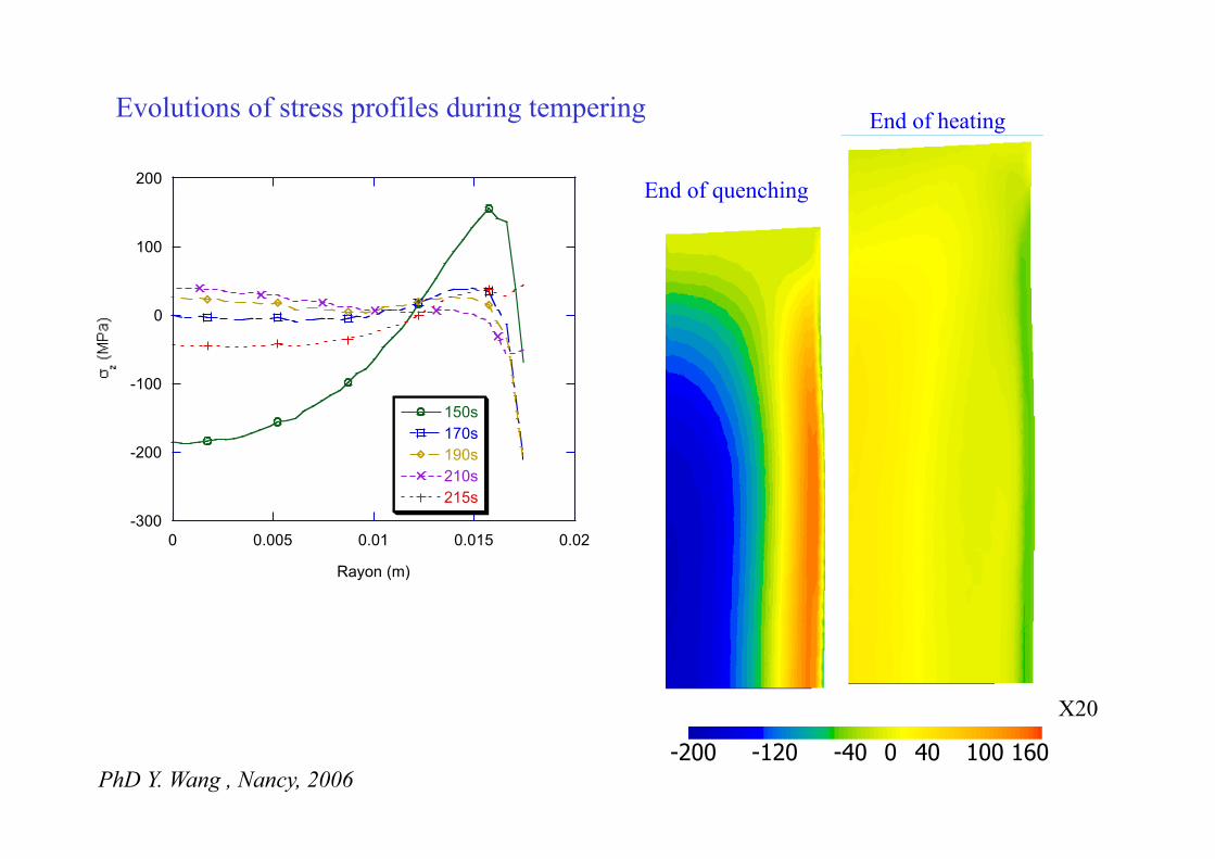
Evolutions of stress profiles during tempering
-200 -120 -40 0 40 100 160
End of quenching
End of heating
X20
PhD Y. Wang , Nancy, 2006
Conclusion - Future developments
• Material point of view - metallurgical models
. global models work for industrial metallic alloys and complex situations prediction of volume fractions . models including nucleation and growth develop more and more
for multicomponent alloys volume fractions and morphological parameters
allow prediction of mechanical properties (Al alloys, Ti alloys…)
. take into account chemical composition gradients (carburizing, carbonitriding, solidification segregations) . effects of prior plastic deformations, effect of stresses
- thermomechanical behaviour with phase transformations
. phenomenological laws exist extension to other metallic alloys (Ti alloys…)
better description of multiphase material (morphology) micro-macro approaches must be further developped
Conclusion - Future developments
• Heat treatment processes - coupling between fluid and solid : developments for vaporizable fluids (experiments and modelling) - include heating processes (furnace, induction…) - in situ measurements (solid + fluid) for rapid processes - chain different processes : liquid metal processing + solidification + forming + heat treatment… • Numerical aspects
Two review papers S. Denis, Revue de Métalurgie CIT/SGM, février 1997, pp. 157-176 S. Denis, P. Archambault, E. Gautier, A. Simon, G. Beck, JMEPG Vol 11 (1), 2002, pp. 92-102
Common work with A. Simon, E. Aeby-Gautier, P. Archambault, J.P. Bellot, B. Appolaire PhD students : FMB Fernandes, C. Basso, J.P. Josserand, D. Farias, F. Saliou, M. Boufoussi, J.F. Ganghoffer, Y. Wen, L. Massicart, M. Zandona, A. Mey, P. Brunet, C. Aubry, J. Ch. Louin, M. Veaux, Y. Wang, Y. Renault, J.F. Douce, M. Haering, L. Mangin, S. Devynck, S. Catteau… In the frame of industrial collaborations CETIM, ARBED, UNIMETAL RECHERCHE, PSA, RENAULT, Creusot Loire Industrie, French Programme SIMULFORGE, European programme VHT, Ascometal, Air Liquide, SNR, Vallourec, ...