
SA-424 FILE NO. 1-0002
46
Transcript of SA-424 FILE NO. 1-0002
SA-424 FILE NO. 1-0002
AIRCRAFT ACCIDENT REPORT WESTERN AIR LINES, INC.
ONTARIO INTERNATIONAL AIRPORT ONTARIO, CALIFORNIA
MARCH 31, 1971 ADOPTED: JUNE 7, 1972
BOEING 720-047B,N3166
NATIONAL TRANSPORTATION SAFETY BOARD Washington, 0. C. 20591
REPORT NUMBER: NTSB-AAR-72-18

. Report No. NTSB-AAR-72-18
I. Title and Subtitle
8.Performing Organization '. Author(s) Ontario. California, March 31, 1971
6.Performing Organization Roeing 720-047B, N3166, Ontario International Airport, Sune 7, 1972 Aircraft Accident Report - Western Air Lines, InC., 5.Report Date
TECHNICAL REPORT STANDARD TiTLE PAGE 2.Government Accession No. 3.Recipient's Catalog No.
Code
Report No.
I . Performing Organization Name and Address IO.Work Unit No.
Bureau of Aviation Safety National Transportation Safety Board
1 1 .Contract or Grant No.
13.Type of Report and Washington, D. C. 20591 Period Covered
12.Sponsoring Agency Name and Address Aircraft Accident Report March 31, 1971
NATIONAL TRANSPORTATION SAFETY BOARD Washington, 0. C. 20591 14.Sponsoring Agency Code
15.Supplementary Notes
I6.Abstract
Flight 366, a Boeing 720B, on a proficiency check flight, yawed and rolled out of control, and crashed while in the process of executing a 3-engine missed-
members and only occupants died in the crash. The weather conditions at Ontario approach from a simulated engine-out ILS instrument approach. The five crew-
were 600 feet overcast, with 3/4-mile visibility in fog, haze, and smoke. The National Transportation Safety Board determines that the probable cause of this accident was the failure of the aircraft rudder hydraulic actuator support fitting. The failure of the fitting resulted in the inapparent loss Of left rudder control which, under the conditions of this flight, precluded the pilotk ability to maintain directional control during a simlated engine-out missed- approach. The existing weather conditions degraded external visual cues, thereby hampering rapid assessment of aircraft performance by the flight check Captain.
17. Key Words Descriptors: Aviation Accidents; Accident Investiga-
i8.Distribution Statement
tion; Instrument Approach, Asymmetric Thrust; Dihedral
worthiness Directives, Service Bulletins; Identifiers: Unlimited distribution lators; Training Accident; Missed-Approach; FAA Air- Released to the Public Effect; Sideslip-Roll Coupling Effect; Aircraft Simu-
19.Security Classification 2O.Security Classification 21.No. of Pages 22.Price Boeiw 720B
(of this report) UNCLASSIFIED
NTSB Form 1765.2 (11/70)
(of this page) UNCLASSIFIED 41
ii

1 . 1.1 1.2 1.3 1.4 1.5 1.6 1.7 1.8 1.9 1.10 1.11 1.12 1.13 1.14 1.15 1.16 2 . 2.1 2.2
3 .
TABLE OF CONTENTS .
Page
Synopsis . . . . . . . . . . . . . . . . . . . . . . . . . . . 1 Investigation . . . . . . . . . . . . . . . . . . . . . . . . . 2 History of Flight . . . . . . . . . . . . . . . . . . . . . . 2
Damage to Aircraft 4 Injuries to Persons 4
Other Damage . . . . . . . . . . . . . . . . . . . . . . . . 4 Crew Information . . . . . . . . . . . . . . . . . . . . . . 4
Meteorological Information 6 Aircraft Information 4
Aids to Navigation . . . . . . . . . . . . . . . . . . . . . . 7 Communications . . . . . . . . . . . . . . . . . . . . . . . 7 Aerodrome and Ground Facilities . . . . . . . . . . . . . . 7 Flight Recorders . . . . . . . . . . . . . . . . . . . . . . 8 Wreckage . . . . . . . . . . . . . . . . . . . . . . . . . . 8 Fire . . . . . . . . . . . . . . . . . . . . . . . . . . 10 Survival Aspects . . . . . . . . . . . . . . . . . . . . . . . 10 Tests and Research . . . . . . . . . . . . . . . . . . . . . 10 Other Information . . . . . . . . . . . . . . . . . . . . . 15
. . . . . . . . . . . . . . . . . . . . . . . . . . . . . . . . . . . . . . . . . . .
. . . . . . . . . . . . . . . . . . . . . . . . . . . . . . . . . . . . . .
Analysis and Conclusions . . . . . . . . . . . . . . . . . . 19 Analysis . . . . . . . . . . . . . . . . . . . . . . . . . . . 19 Conclusions . . . . . . . . . . . . . . . . . . . . . . . . . 26 [a) Findings . . . . . . . . . . . . . . . . . . . . . . . . 26 (b) Probable Cause . . . . . . . . . . . . . . . . . . . . . 27 Recommendations . . . . . . . . . . . . . . . . . . . . . 27
Appendices Appendix A
Appendix B
Appendix C
. . . . . . . . . . . . . Investigation and Hearing 31
Flight Crew Information . . . . . . . . . . . . . 32
Aircraft Information . . . . . . . . . . . . . . . 34
Attachments Attachment 1
Attachment 2
Attachment 3
Rudder Power Control Unit (Series Yaw Dunper)
Probable Flight Path
Wreckage Distribution
... u1

File No. 1-0002
NATIONAL TRANSPORTATION SAFETY BOARD
AIRCRAFT ACCIDENT REPORT Washington, D. C. 20591
Adopted: June 7, 1972
WEfXERN AIR LINES, INC. BOEING 720-047B, N3166
ONTARIO lNTERNATIONAL AIRPORT ONTARIO, CALIFORNIA
MARCH 31. 1971
SYNOPSIS
A Western Air Lines, Inc., Boeing 720-047B, N3166, operating as Flight 366, crashed on the Ontario International Airport, Ontario, Cali- fornia, at 0633:29 Pacific standard time, on March ,31, 1971. All five crewmembers, the only occupants of the aircraft, were fatally injured. The aircraft was completely destroyed by impact and ensuing fire.
Flight 366, a routine proficiency check flight, was executing an Instrument Landing System approach to Runway 25 at Ontario with the No. 4 engine reduced to idle power to simulate an engine-out approach. The flight had been cleared to land or to execute a missed-approach proce- dure at the pilot-in-command's discretion. At decision height, approximately 100 feet above the runway, a simulated engine-out missed- approach procedure was initiated. The aircraft began to climb and the landing gear was retracted. The aircraft continued to climb to an altitude of about 500 feet above the runway while rotating to the right about its roll and yaw axes. As the rotation continued, the nose of the aircraft descended to a near-vertical downward position, and the aircraft crashed on a south- easterly heading approximately 3,140 feet west of the approach end and 420 feet north of the centerline of Runway 25.
The weather at Ontario about 3 minutes after the accident was: 600 feet overcast, 3/4-mile
visibility in fog, haze and smoke, wind from 250" at 4 knots, and a Runway 25 visual range of more than 6,000 feet. Similar conditions were reported 34 minutes prior to the accident, except the ceiling and visibility were 500 feet and 5/8-mile, respectively.
Investigation revealed that the rudder hydrau- lic actuator support fitting had failed, resulting in the complete loss of left rudder control shortly after commencement of the missed- approach. The fitting failed due to a combina- tion of stress-corrosion cracking and high tensile loading.
The National Transportation Safety Board determines that the probable cause of this accident was the failure of the aircraft rudder hydraulic actuator support fitting. The failure of the fitting resulted in the inapparent loss of left rudder control which, under the conditions of this flight, precluded the pilot$$ ability to maintain directional control during a simulated engine-out missed-approach. The existing weather conditions degraded external visual cues, thereby hampering rapid assessment of air- craft performance by the flight check captain.
Based on evidence gathered in the initial investigation of the accident, the Safety Board recommended to the Federal Aviation Admini- stration on April 9, 1971, that: (1) The inspec- tion time periods associated with the rudder hydraul ic ac tua to r suppo r t fittings on B-707/720 aircraft be reevaluated, and (2) all ,
1

B-707/720 operators be informed of the po- tential operational hazards associated with low altitude, high-asymmetric thrust operations.
The FAA responded to these recommenda- tions by: (1) issuing a new Airworthiness Direc- tive, on April 27, 1971, requiring more frequent inspections of the support fitting, and (2) issuing an Operational Alert Notice on April 9, 1971, informing all B-707/720 operators of the fitting failures and advising that simulated engine failures not be performed at low altitudes until certain conditions had been met.
After further inquiry into the support fitting problem, Safety Board consultations with the manufacturer and the FAA resulted in the e s tablishment of an earlier support fitting replace- ment (or modification) date. This was con- sidered necessary to further reduce the possibili- ties of in-flight failures of the fitting.
Based on the evidence gathered in the inquiry, the Safety Board further recommended to the FAA that: (1) there is a need for more definitive information or warnings in Airworthiness Direc- tives; (2) improvements are needed in pilot train- ing programs; (3) simulated engine($-out manu- evers be performed, to the maximum extent pos- sible, either in flight simulators or at altitudes that will insure safety if unexcpected aircraft emergencies are encountered; and (4) continu- ous surveilance is needed of aircraft components made of materials known to be susceptive to stress-corrosion cracking. The latter recommen- dation is also made to associations representing aviation manufacturers and operators.
The Board also recommends that the Air Transport A s ~ ~ , n ~ ~ ~ . . ~ G ~ ~ ~ A ~ ~ ~ ~ ManufacturersAof alrcra t adrames, accessones, and components , include more definitive information and warnings in service bulletins. Finally, the Board recommends to the Air Transport Association and the National Air Transportation Conferences that they encourage their members to establish flight safety offices.
2
1. INVESTIGATION
1.1 History crfFlight
Western Air Lines, Inc., Flight 366 (WAL 366), a Boeing 720-047B, N3166, was scheduled on March 31, 1971, as a training flight for the purpose of administering proficiency flight checks to two Western captains. The crew con- sisted of: (1) a check captain (the pilot-in-com- mand), seated in the right-hand pilot seat, per- forming first officer duties, (2) a captain seated in the left-hand pilot seat, flying the aircraft and receiving a proficiency check, and (3) a second officer performing flight engineer duties. Seated behind the left-hand pilot's seat on two tandem jump seats were a captain who was to receive a proficiency check later in the flight and a captain who joined the crew shortly prior to departure to observe flight check procedures.
from the Western flight dispatcher at 0520' on The check captain received a flight briefing
the morning of the flight. The briefing included weather reports and forecasts, weight and balance data, Notices to Airmen, fuel load, and
Rules (IFR) flight plan had been filed with the clearance information. An Instrument Flight
Los Angeles Air Traffic Control Center request- ing clearance from Los Angeles International Airport (LAX), Los Angeles, Cdifornia, to Ontario Internation Airport (ONT), Ontario, California, via the V-16 airway, and return to LAX, with an estimated 2 hours en route. An altitude of 5,000 feet mean sea level (m.s.1.) was requested en route to ONT. A total of 50,000 pounds of fuel was on board N3166.
WAL 366 departed LAX from Runway 25R at 0610 and proceeded under the direction of L o s Angeles Departure Control. At 0615:30,
'All times used herein are Pacific standard times (P.st.) b a d on the 24-hour clock.
7
W.
CC CO
t a re CI (1 t h ax as f e fc
rz a1 rt 11 cl C tl tl I<
S€
w w C
a e S
C
( t c t
T
I
?-
5 (WAL .heduled : for the y flight ‘ew con- -in-com- eat, per- n seated raft and L second . Seated tandem eceive a
and a prior to xes. briefing j20’ on ncluded ;ht and lad, and
Flight rith the request- lational .nia, to Intario, turn to Ute. An
50,000
ay 25R :tion of 615:30,
5.1.) was
st.) based
WAL 366 was cleared direct to Ontario and control was transferred to Ontario Approach Control.
At 0616:25, WAL 366 established radio con- tact w i th Ontario Approach Control and requested radar vectors to a point 3 miles east of Colton’ for an Instrument Landing System (ILS) approach to Runway 25 at Ontario, “with the ~ p t i o n . ” ~ The request was acknowledged and the landing and weather information given as: Runway 25 in use, a measured ceiling of 600 feet overcast, visibility fiveeights of a mile in fog, haze and smoke, wind calm, altimeter setting 29.92 inches, and a Runway 25 visual range of more than 6,000 feet. WAL 366 acknowledged receipt of the information and received radar vectors to intercept the Ontario ILS localizer course. At 0620:50, WAL 366 was cleared for the approach “with the option.” The Cockpit Voice Recorder (CVR) disclosed that the check captain retarded the power lever on the No. 4 engine at about 0621 to simulate a loss of that engine. The engine failure checklist was completed and the No. 4 engine power lever was checked in the idle position. The in-range checklid was completed several minutes later; and at 0628:25, Ontario Approach Control established WAL 366’s position at 1/2-mile southeast of Colton, and cleared the flight to
Ontario Tower was established at 0629:05 and contact Ontario Tower. Radio contact with
the flight continued inbound on the localizer course. The CVR tape disclosed that at about this time the captain receiving the check stated, “In the event of a missed-approach, remember, I want you to get my V-bars.”’ The check captain
‘A nondirectional radia beawn located on the Ontario ILS loalizer wwse, 5.3 mileseast of the outer marker. 3The option either to land or exeate a missed-approach pro-
4A lid of items that are acmmplished when the aircraft is cedure at the pilot-in-wmmand’sdistion.
about 25 miles from the destination airport.
responded, “I’U get ‘em out of the way.” WAL 366 reported over the outer marker at 0630:45 and was again cleared for the “option” by Ontario Tower. This was the last known radio contact with WAL 366.
At 0631:42, the flight check captain said, ‘‘Okay, you have a thousand feet and you have ref.”6 Similar altitude and airspeed calls were made at 900, 800, 500, 400, and 300 feet. At 0633:08.2, the check captain said, “Minimums, no airport!” The captain flying the aircraft responded with, “max power, flaps thirty,” and sounds of an increase in engine compressor rotational speeds were recorded. At 0633:14, the captain receiving the check called, “Positive rate, gear up,” and, following sounds similar to landing gear control handle actuation, the check captain said, “Positive rate, gear comin’ up.” At 0633:20.4, the sound of an engine compressor stall was recorded, followed 0.6 second later by another similar sound. The sounds of two more compressor stalls were recorded at 0633:21.7, and at 0633.23.4, the captain seated in the first ,jumpseat said, “Corn”on!”This was followed 1.4 seconds later by an exclamation from the same captain, “Roll it all the way over!” Sounds of ground impact were recorded at 0633:28.7.
Several witnesses reported that the aircraft descended low over the runway and then began to climb. As the climb continued, several loud popping sounds were heard, flames were seen extending &om the rear of the engines under the right wing, and the aircraft was observed to yaw
progressed, the nose of the aircraft descended to and roll to the right. As the maneuver
5The Collins Fljght Director FD-108 instrument mntains a V-bar wmmand indicator that gives airaaft attitude information to
removed from view during a miszed-approach procedures as they the pilot. Some pilots prefer that the bars be deactivated and
may present a confusing picture when an immediate heading change is to be acwmplished. 6 A n indicated airspeed that is 1.3 times the stall speed of the aircraft for a particular gross weight and mnfguration.
3 I

I I 1
a near-vertical downward position and the air- craft struck the ground on a southeasterly heading.
Following their report of outer marker passage, the tower controller confirmed the flight’s clearance for the “option” and main- tained a listening watch on the tower radio frequency. After their acknowledgement of the clearance, the tower controller heard nothing further until his attention was attracted by an unintelligible transmission on the tower frequen- cy, followed immediately by sounds similar to muffled explosions. He looked to the east and observed N3166 in a nosedown attitude about 300 to 400 feet above the ground. The under- side of the fuselage appeared to be facing west, and, as he watch, the aircraft struck the ground and exploded.
The accident occurred below an overcast, in daylight conditions. The location was at latitude 34” 03‘ N., longitude 117” 36’ W., at an eleva- tion of approximately 929 feet m.s.1.
1.2 Injuries to Persons
Injuries crew Passengers Others
Fatal 5 0 0
Nonfatal 0 0 0
None 0 0
Pathological examinations of the #crew- members revealed no significant disease. No problems of health, fatigue or concern could be identified by persons in recent close contact with the pilots flying the aircraft.
1.3 Damage to the Aircraft
Impact forces and ensuing fire completely destroyed the aircraft.
1.4 Other Damage
No other damage occurred.
1.5 Crew Information
The flightcrew was certificated and had com- pleted the fllght and ground training programs required by existing regulations. See Appendix B for detailed information.
The captain who was flying the aircraft and receiving a proficiency check was also qualified and current in Boeing Model B-727 aircraft. He had originally qualified as a B-720B captain on March 31, 1969, and in October 1969, had com- menced training in the B-727. His last pro-
October 16, 1970, in the B-727, and he had f ic iency check was successfully completed
received a line check in the B-727 on March 13, 1971. He had passed a proficiency check in the B-720B on April 28, 1970. He satisfactorily completed the flight simulator portion of his B-720B proficiency check on March 26, 1971, and was in the process of receiving the flying po r t i on of the check when the accident occurred. He had flown a total of 172 hours in the 9Oday period preceding the accident, 15 hours of which were in the B-720B or B-707’. He had not flown either the B-707 or B-720B in the preceding 3Oday period.
1.6 Aircraft Information
N3166 was owned and operated by Western Air Lines, Inc. I t was properly certificated.
within limits at the time of takeoff from LAX The gross weight and center of gravity were
and at the time of the accident. The aircraft had been serviced with 4,442 gallons of jet type “A” kerosene which gave, when added to the fuel on board, a total fuel weight of 50,000 pounds. For additional aircraft information, see Appendix C.
The flight report logs of N3166 for the 3-month period preceding the accident were examined. Two potentially pertinent items appeared repeatedly. The first item concerned
mi in en en th PC ac dl it1 t C
se
T: tt ai tl
h,
li P
F a, 1( r1 f
cc
S
C
C
1: 1 I F f
poses, the B-720B and B-707 are mnsidered similar aircraft. ‘For qualification, type rating, and flight time remrding pur-
4

misalignment of the engine power levers in that, in order to equalize thrust output for the four engines, the power levers for the Nos. 2, 3, and 4 engines had to be progressively retarded from the No. 1 engine lever position towards the idle position. This complaint had been deferred, in accordance with Western maintenance proce- dures, pending engine trim checks. The second item concerned a slowness of the No. 3 engine to accelerate from low-power to high-power settings. This item had received maintenance
The first officer on the flight that had preceded corrective action prior to the accident flight.
the accident flight stated that neither item had affected the controllability of the aircraft during the course of his flight.
had been complied with, including AD 69-13-2 All applicable Airworthiness Directives ( A D )
pertaining to the integrity of the rudder hydrau- lic actuator support fitting (Part No. 65-5937-8). Force and motion from the rudder hydraulic
lower lugs of this fitting for operation of the actuator are transmitted through the upper and
rudder. See Attachment 1 for details of the fitting.
On May 1, 1969, The Boeing Company had sent a telegraphic message to all B-707/720 operators recommending that a visual inspection of the rudder hydraulic actuator support fitting be made on all B-707/720 aircraft. The Western Air Lines E<lgineering Department issued Engineering Authorization No. 720-20755 on May 2, 1969, referencing the Boeing message as follows:
“Subject
Rudder Hydraulic Actuator. Support Fitting Assembly Inspection -
Description Several KC-135 airplanes and one 707-300B airplane had experienced cracking of the upper and lower lugs and web of the rudder
Boeing has just been advised of a second hydraulic actuator support fitting assembly.
incident by another operator where complete failure of the actuator attach (sic) lugs was experienced on a 707-300C airplane at
5
approximately 10,300 f l i h t hours. Failure occurred during training with two engines at idle. At the earliest possible time consistent with scheduling requirements, a one-time visual inspection of the subject fittings is to be accomplished. WAL Engineering will
The Boeing Company. Any fittings found report the outcome of these inspections to
cracked are to be replaced before further fliht.” No cracked fittings were found on Western’s
aircraft as a result of those inspections. On June 2, 1969, Boeing issued Service Bul-
letin (SB) 2903, recommending an inspection and replacement program for the rudder hydrau- lic actuator support fittings made of 7079-T6 aluminum alloy on all B707/720 aircraft. On June 6 , 1969, the Federal Aviation Administra- tion (FAA) issued AD 69-13-2, establishing a
based on SB 2903. mandatory inspection and replacement program
AD 69-13-2 required, within 75 hours time in service after June 6, 1969, that a visual inspec- tion with magnification, or a dye penetrant or eddy current inspection, be made in accordance with the instructions in SB 2903 to determine the existence of any cracks in the fitting. If no cracks were found, a repeat inspection using the above methods was required a t intervals not to exceed 325 hours time in service, up to a maxi- mum of 1,400 hours time in service subsequent to June 6, 1969. If cracks were found within the oversizhg limits specified in Part I1 of SB 2903, the fitting could be reworked by incremental reaming and fitted with a new aluminum-nickel- bronze bushing, or could be replaced with one made of 7075-T73 aluminum alloy material. If the cracks were too large to be reworked, the fitting had to be replaced with either a similar fitting containing the new aluminum-nickel- bronzebushing, or anew 7075-T73 fitting. In any event, within 1,400 hours time in service after June 6, 1969, the new aluminum-nickel-bronze bushings had to be installed. Following that installation, an inspection for cracks was re- quired at intervals not to exceed 1,200 hours in service untila new 7075-T73 fitting containing a
flanged aluminum-nickel-bronze bushing was installed. Installation of the 7075-T73 fitting constituted terminating action for AD-69-13-2.
Boeing issued Revisions 1, 2, 3, and 4 to SB 2903 on June 4, 11, and 20, 1969, and December 22, 1969, respectively. These revi- sions dealt with technical changes and aligned the Boeing recommendations with the FAA requirements of AD 69-13-2. The latter was amended on July 24, 1969, without substantive change.
On February 3, 1971, Boeing issued Revision 5 to SB 2903, recommending that an ultrasonic inspection of the lug bores be conducted in addi- tion to a visual, dye penetrant, or eddy current inspection of the fitting in general. An eddy current inspection with lug bushings removed was deemed an acceptable alternative to the ultrasonic. It was also recommended that a one- time ultrasonic inspection be accomplished at an early opportunity. Cited as a basis for these recommendations was one operator's experience of a complete fitting failure 80 hours after installation of a new bushing and a repeat visual inspection, along with a subsequent ultrasonic inspect ion program which disclosed seven cracked fittings among 136 that had previously passed other inspections.
The support fitting on N3166 had been inspected, reworked, and fitted with aluminum- nickel-bronze bushings on July 28, 1969. A visual and dye penetrant inspection of the fitting had been made on February 8, 1971. No cracks were found on either inspection. About 452 hours time in service were accumulated by N3166 from February 8,1971, to the day of the accident.
A revision to AD 69-13-2, effective March 18, 1971, required, within the next 600 hours time in service, that an ultrasonic or, after removal of all bushings, a dye penetrant or eddy current inspection be made of the support fitting in' accordance with Revision 5 of SB 2903. N3166 had accumulated 8 2 3 2 hours since March 18, 1971, and was not due an inspection for another 517:48 hours.
6
During the period June 2, 1969, to March 31,
fleet of B-707/720 aircraft had been replaced 1971, a total of 12 support fittings on Western's
with fittings made of the 7075-T73 material. Of those 12, two had been reported on FAA Main- tenance Reliability Reports (MRR) as cracked beyond rework limits. Western's policy was to replace any cracked fittings with 7075-T73 fittings, rather than rework them as authorized by AD 69-13-2.
Effective April 27, 1971, the FAA issued AD 71-9-2 superseding AD 69-13-2. The new AD dealt with the same problem. However, it intensified the inspection program on the B-707/720 support fittings, and required replacement of the 7079-T6 fitting within 5,400 hours time in service but, in any event, prior to further flight after October 1, 1972.
1.7 Meteorological Information
The check captain was briefed by the Western flight dispatcher and a weather display was available in the WAL dispatch office.
The surface weather observations for Ontario at the times indicated were:
0459 Record special, measured 700 feet over- cast, visibility 1 3/4-miles, haze, smoke, temperature 52"F., dew point 48"F., wind calm, altimeter setting 29.91 inches.
0542 Special, measured 600 feet overcast, visibility 5/8-mile, fog, haze, smoke, temperature 51"F., dew point 49"F., wind calm, altimeter setting 29.92 inches.
0559 Measured 500 feet overcast, visibility 5/8-mile, fog, haze, smoke, temperature 51"F., dew point 49'F., wind 250" at 4 knots, altimeter setting 29.93 inches, Runway 25 visual range 6,000 feet plus, breaks in the overcast.
0636 Special, measured 600 feet overcast, visibility 3/4-mile, fog, haze, smoke, temperature 51" F., dew point 49"F.,
31, 19 Sun
1.8 A
The with : The i~ The (
outer on thl
thresh and (
the IT feet a 200 : elevat polic) traini
Th appro made runw; left t VOR instar 366 1
for tl tic ar that 2
01: OUtSt
concl ONT pone FAA presc
1.9
N( repol

7
wind 250" at 4 knots, altimeter setting 29.92 inches, Runway 25 visual range 6,000 feet plus.
Sunrise at Ontario occurred at 0540 on March 31. 1971.
1.8 Aids to Navigation
The Ontario International Airport is equipped with an ILS precision approach to Runway 25. The inbound localizer course is 255" magnetic. The Colton nondirectional radio beacon, the
on the localizer course at distances of 11.2, 5.9, outer marker, and the middle marker are located
and 0.6 miles, res ectively, from the runway threshold. The gli B e slope crossing altitude at the middle marker is 1,145 feet m.s.l., or 216 feet above the ground. Decision Height (DH) is 200 feet above the runwa touchdown zone elevation of 929 feet m.s. . r It was Western's policy, and an FAA requirement, to use a training DH of 100 feet for pilots-in-command.
The published Runway 25 ILS missed- approach procedure specifies that a climb be made to 1,300 feet m.s.1. while maintaining runway heading (255" magnetic), after which a left turn is required to proceed to the Ontario VOR while climbing to 4,200 feet m.s.1. In this instance, CVR information indicates that WAL 366 was cleared by Ontario Approach Control for the "option" with a left turn to 210" magne- tic and a climb to 4,000 feet m.s.1. in the event that a missed-approach was elected.
On the day of the accident, there were no outstanding Notices to Airmen or pilot reports concerning the status of the aids to navigation at O W . Subsequent to the accident, all com- ponents of the ILS were flight checked by the FAA and found to be operating within prescribed tolerances.
1.9 Communications
No problems with communications were reported during the flight from LAX to ONT.
1.10 Aerodrome and Ground Facilities
Runway 25 at Ontario is the primary instru- ment runway. It is 9,982 feet long with a useable length of 8,882 feet. It is 150 feet wide and is constructed of asphalt and concrete. The airport elevation at its highest point is 952 feet m.s.l., and the Runway 25 touchdown zone elevation is 929 feet m.s.1. A 1,000-foot overrun extends eastward from the threshold of Runway 25.
A US. Standard Configuration A high inten- sity approach lighting system with sequence flashing lights is installed in the overrun and approach path leading to Runway 25. These lights were on and set Step 5 (maximum inten- sity) at the time of the accident. High intensity runway lights are installed and were set at Step 4, a slightly lower intensity than Step 5.
The Ontario Airport firefighting services were provided by the City of Ontario Fire Depart- ment (OFD). A central dispatch system, located at OFD headquarters in the city of Ontario, was used to dispatch equipment. A direct telephone line to the central dispatcher was provided in the O W Control Tower, and the tower controller used it to notify the central dispatcher of the crash. Direct radio communication between the tower and the firefighting units was used to control the latter while on the airport taxiways and runways.
A total of 17 units from the OFD responded to the crash. Three units from the fire station located on the airport were at the crash site about 2 minutes after the impact occurred. Three units from the headquarters fue station were delayed 2 or 3 minutes by a train pro- ceeding along tracks adjacent to the airport. The Cal i fornia Air Nat iona l Guard provided assistance with two 1,000 gallon, 0-11 crash trucks.
pounds of dry chemical were used in extinguish- An estimated 25,000 gallons of water and 350
ing the &e. The fwe was brought under control in approixmately 1 hour.
7

1.1 Flight Recorders
a. Flight Data Recorder
A Fairchild Industrial Products Flight Data Recorder (FDR), Model 5424-501, Serial No. 5680, was aboard N3166 at the time of the accident. It was recovered from the wreckage and examined at the Board's Washington office. The FDR case was clean with no evidence of exposure to either smoke or heat. The top of the case's midsection was crushed inward, but the foil recording medium was undamaged.
A FDR readout was made of the last 5:16 minutes of the flight, beginning 5 minutes prior to the time of the lowest altitude recorded on the final approach at ONT.
In addition, an altitude measurement was made at the point where the aircraft was in the takeoff position on Runway 25R (elevation 100 feet) at LAX. The measurement reflected a recorded altitude of 225 feet, or 125 feet too high. The FDR altitude trace reflected a value of 5,225 feet at the reported cruise altitude of 5,000 feet m.s.l., or 225 feet too high.
The recording accuracy tolerances for the FDR parameters are:
Altitude . . . . . . . * 100 feet at sea level to f 700 feet at 50,000 feet
Airspeed . . . . . . . f 10 knots
Heading . . . . . . . f 2 "
Vertical Acceration . . . . . +0.2 g
Time . . . . . . . . . * 1 percent in 8 hours
b. Cockpit Voice Recorder
N3166 was equipped with a Fairchild Industrial Products Cockpit Voice Recorder (CVR), Model A-100, Serial No. 2517. It was found clear of the aircraft structure, and had sustained slight damage from impact but none due to fire or heat.
A transcription was made of that portion of the recording covering the last 12:43 minutes of
fhght. Voice identification was accomplished by persons familiar with the WAL crewmembers aboard N3166.
c. Correlation of FDR, CVR, and Eye Witness Information
A probable flghtpath profiie of the last 34.2 seconds of flight was constructed &om FDR data, runway and ILS geometry, and eye- witness reports. The flightpath was plotted from the point of impact back to the middle marker location using an approximate groundspeed and eyewitness accounts of the maneuvers. CVR information was added by correlating the actual times established for the CVR comments with the calculated (rate x time) linear base of the fhghtpath plot. The probable flightpath is an approximation of the actual flightpath, and it should not be used for finite measurements or values. See Attachment 2 for the probable flight- path profile.
1.1 2 Wreckage
N3166 struck the ground 420 feet north of the centerline and 3,140 feet west of the threshold of Runway 25. The major portion of the wreckage was confined to an area approxi- mately 300 feet by 350 feet. It was aligned generally on a heading of 160" magnetic. See Attachment 3 for wreckage distribution details.
subsequent to impat. Portions of the fuselage Most of the aircraft was consumed by fire
forward to and including the cockpit area were structure from Fuselage Station (FS) 960
located in the main wreckage. The major portion of the airkame was reduced to fragments and molten metal. Various components were located and examined in an effort to determine precrash operative conditions.
All wing trailing edge flap jackscrews were located. Extension measurements corresponded to a 30" flap position. The leading edge flap actuators were in the extended configuration. Portions of all of the left wing spoilers were attached to the wing structure, with hydraulic actuators and tubing intact; the spoiler panels
8
w
wen panc ext e retr; rem, posi
T mea UP t h e gear T
the 146 sect stra T
had rudt wer righ ,I
hYd traf atta fitt was verl seP dur 19; POI 1% 25.
the rod alu we] alu we: wa
rec wa b o act t es

T
were in the retracted position. The No. 6 spoiler panel on the right wing was in a partially extended position; the remaining panels were retracted. The No. 6 spoiler actuator was removed for examination. The actuator piston position reflected a retracted spoiler.
The horizontal stabilizer jackscrew extension measurement corresponded to an aircraft nose- up stabilizer position of 3.0 to 3.5 units. All
gear actuators corresponded to a
the fuselage in an irr ular tear between FS The empennage section had separated from
1462 and FS 1543. AI 7 control cables to this section were completely separated, with reduced strand diameters at the breaks.
had separated &om the empennage section. The The vertical stabilizer containing the rudder
rudder and rudder control tab hinge fittings were intact. The rudder was displaced to the right.
The upper and lower lugs of the rudder hydraulic actuator support fitting were broken transversely through the bolt holes provided for attachment of the actuator rod-end to the fitting. The separated portion of the upper lug was found in the actuator compartment of the vertical stabilizer. An unsuccessful search for the separated portion of the lower lug was conducted during the investigation. Later, on June 23, 1971, an airport employee found the separated portion 225 feet south of the center line and 1854 feet west of the approach end of runway 25.
The bolt that secures the actuator rod-end to the support fitting was intact on the actuator rod-end. A corrosion resistant slip bushing, an aluminum-nickel-bronze bushing and a washer were intact on the head-end of the bolt. An aluminum-nickel-brone bushing and a washer were intact on the nut-end of the bolt. The nut was secure and the safety pin was in place.
The rudder hydraulic control unit was recovered intact from the wreckage. The unit was placed in a test fixture and was operated by both the input lever and the yaw damper actuator control assembly. Both operations met test specifications. The rudder control tab lock
three gear up land? and ocked position.
9
mechanism released properly when hydraulic pressure was removed from the control unit. The horizontal stabilizer electric trim motor was functionally tested. Both clutch settings were normal at 700-inch-pounds, with current draws at those settings of 10 to 13 amperes.
The Nos. 2 and 3 engine hydraulic pump supply shutoff valves were recovered in the areas of their respective engines. Both valves were in the open position. Both hydraulic pumps had been subjected to heat damage and could not be rotated. The splined drive couplings for both pumps were intact. The two electrically driven alternating current, auxiliary hydraulic pumps were recovered and examined for rotational scoring; none was observed. The drive couplings for both pumps were complete.
Examina t ion o f cockpit control panels disclosed the No. 2 Engine Hydraulic Pump Switch missing and the No. 3 Engine Hydraulic Pump Switch in the “ON” position. The No. 1 Auxiliary Hydraulic Pump Switch was missing and the No. 2 switch was broken. The Rudder Power Switch was also broken.
N3166 was equipped with four Pratt & Whitney JT3D-3B engines. All four engines had separated &om their pylons and the engine cowlings had separated &om their respective engines.
The turbine, compressor, or fan blades of the four engines were bent opposite to the direction of rotation. None of the engines showed any signs of preimpact over-temperature conditions. The compressor bleed valves on the Nos. 1 and 2 engines were in the closed position; those on the Nos. 3 and 4 engines were in the open position. These valves were designed to close whenever N, compressor speed reached a value exceeding 80 percent. The N, compressor rear hubs were fractured on the N, compressors &om the Nos. 3 and 4 engines. The tie-bolts were sheared on the N2 compressors from the Nos. 1 and 2 engines.
The thrust reverser systems on all four engines were in the stowed configuration. There was no evidence of either distress or a lack of lubrica- tion on the bearings, gears, or drives of any of

I -1 ~-
the engines. The main oil screens from all engines were free of contamination. The engine fuel shutoff valves were in the open position.
1.13 Fire
There was no evidence of preimpact fire. The aircraft exploded on impact and was almost totally consumed by fue. (See Section 1.10 above for firefighting report.)
1.14 Survival Aspects
This was a nonsurvivable accident.
1.15 Tests and Research
a. CVR Sound Spectrographic Examination
Air Lines B-720B for the purpose of recording A test flight was conducted in a Western
engine sounds on the CVR tape. Recordings were made under selected operational conditions and at various engine ower settings. The flight test tape yielded the P ’ ollowlng sound frequency data associated with the rotational speeds of the N, com ressors, as expressed in percentage of N, speecl
100% N, . . . . . . . . . . . 3820 Hz.
90% N, . . . . . . . . . . . 3460 Hz.
80% N, . . . . . . . . . . . 3100 Hz.
70% N, . . . . . . . . . . . 2730 Hz.
ambient noise in the 500-Hz to 2300-Hz range, Due to t h e presence of considerable
it was not possible to identify positively the spectrogram traces associated with a flight idle power setting (40% N1 ). However, calculation of the approximate frequency value at that speed was 1550 Hz.
Sound frequency spectrograms were made from both the test tape and the accident tape. These spectrograms were then compared in an effort to determine N3166 engine rotational speeds during the last seconds of flight.
This comparison disclosed the existence, on the accident tape, of a 2950-Hz resonance
10
(equivalent to a speed of 76 percent N , ) for about 8 or 9 seconds prior to the time the call “minimums, no airport” was made. At the con- clusion of that call, the compressor sounds on the accident tape increased in frequency at the rate of about 500 Hz per second until they stabilized at 4140 Hz approximately 3 seconds later - this fiequency corresponded to a speed of about 109 percent N1 . There was no evidence of a change in the rate of N1 speed until an additional 8 seconds later, immediately follow- ing the sounds of the fust compressor stall. At that time, a decrease in fiequency was apparent with the continued presence of the 4140-Hz resonance.
The above frequency decrease occurred at a rate of about 500 Hz per second for the first 2 seconds, and then at a rate of 100 Hz per second for the next second. It reached a low of about 3040 Hz, or about 78 percent N1 , at 0633:23.4.
At 0633:23.6, following the remark “come on,” a fiequency increase, which occurred at the rate of 500 Hz per second, was apparent for 0.4 second.
Between 0633:26.0 and 0633:26.5, a resonance of 2645 Hz appeared, representing a speed of 67.7 percent N, . At 0633:28.6, or 0.1 second prior to the sounds of impact, a resonance of 3645 Hz (95 percent N , ) appeared.
b . Metallurgical Examination of the Rudder Hydraulic Actuator Support Fitting From N3166
Both the upper and lower lugs of the support fitting from N3166 had separated from the main body of the fitting due to fractures extending through the actuator attachment bolt holes. The fracture surfaces were examined with the aid of a binocular microscope, and by
one-half percent of the left fracture face and 6.3 electron fractographic techniques. Eleven and
percent of the right fracture face had been produced by stress-corrosion cracking on the
upper fractur been 1 was m to aTl
C
Stress-
inform that 1 fitting aircraf
P single by thm the pc When penetl Additi ultrasc aforer possib were I
preser crack associ the r:
the in cracks appro cracks
phic I
8Stres4 of (1) cient), sustaim (quencl straight interfa mnditi terials intergra 9 ~ 0 t 0 , precisel m n t m tone ir
upper lug.' The remainder of the upper lug fractures and all of the lower lug fracture had been produced by tensile rupture. The fitting was made of 7079 aluminum alloy, heat treated to a T6 temper.
c. Nondestructive Inspection Methods and Stress-Corrosion Cracking
A consulting metallurgist provided information to the Board on the results of tests that he had conducted on a cracked support fitting removed from another Western B-720B aircraft.
A visual inspection of the fitting revealed a
by the dye penetrant met od, which revealed single crack in one of the lu s It was then tested
the possible existence of another smaller crack. When fur ther t es ted with a fluorescent penetrant, the smaller crack was clearly evident. Additional inspection by edd current and ultrasonic methods clearly teve J ed both of the aforementioned cracks with indications of the possibility of other cracks. Radiographs (x-rays) were then taken of the lug. These showed the presence, extent, and depth of the two major cracks, and indications of smaller cracks associated with one of the major cracks. When the radiographs were subjected to a photogra-
the indications associated with one of the ma'or phic enhancement processv, it was found that
cracks actually were smaller cracks; addition ad y, approximately a dozen indications of other cracks were disclosed.
8'
'Strewwnosion Racking results from the wmplex interaction o f (I) a corrosive environment (a humid atmosphere is mffl- cient), with (2) a susceptible m a t e d that is in a state of sustained tensile stress. The stress may he either residual (quenching after solution heat threatment, machining, and straightening) or applied (induced by normal loading, misfits, interference fits, and clamping). The wmhinatmn of these two wndithns produces brittle fractures in othawise ductile ma- terials In aluminum alloys the path of the fracture is always intergranular.
precisely controlled printii exposures of a hkh lithographic 9 ~ o t o ~ p ~ c enhancement consists essentially of a series of
wntrast film These f i i s are designed to transfer a continuous tone image into a black and white image.
For incipient crack detection, the ultra- sonic and eddy current methods of non- destructive inspection are the best methods available. The radiograph with photographic enhancement is superior to either of the above, but it is still in development and the necessary equipment was not generally available. An added advantage was that the photographic end products form a permanent record, to which future enhanced radiographs could be compared for indications of crack formation trends.
Predictions on the rates of crack propaga- t i on associated wi th stress-corrosion are extremely difficult to make with any accuracy. In laboratory tests, crack propagation from the effects of stress-corrosion have actually been observed. In o t h e r cases, under similar conditions, comparable crack propagation has taken a considerable period of time. Also, variations in crack propagation rates can be expected between outwardly identical parts due to internal differences in grain-flow and residual stresses from heat treating and machining.
As a part of the investigation of this accident, the Safety Board reviewed the history of stress-corrosion cracking in aluminum alloys, including the 7079 and 7075 type alloys.
The problem of stress-corrosion cracking has been a subject of concern in the aircraft
of the knowledge on the subject has been industry for more than 40 years. However, much
developed in the past 10 to 15 years, due to the demands for greater erformance and the increasing occurrence o P " service fadures. This
accura te iden t i f i ca t ion of materials and increased knowledge has led to the more
thereto. As a result, aircraft design engineers processing methods providin greater resistance
have turned increasingly to the use of alloys, tempers, and fabricating methods that will avoid or minimize the problem. Recent examples of this include the selection of 7075-T73 material for use in the McDonneU Douglas DC-10, and the use of 2024T3 aluminurnclad material in
penalties were imposed in the process. Also, !ue t h e Lockheed 1011, even though wei ht
to i t s res is tance 'to intergranular attack, extensive use was made of the 7075-T76 alloy in
11
I
I I
1 rJ i
1 i
4
the wings and horizontal stabilizer of the L 1011. The 7079 alloys were not used because of their known susceptibility to stress-corrosion cracking.
d. The Boeing Company Support Fitting Evaluation Tests
The Boeing Company conducted a series of post accident tests on nine 7079-T6 support fittings which had been removed from aircraft after 8,900 to 39,615 hours in service. The objectives of the tests were to: (1) generate, by exposure to various environmental conditions, stresscorrosion cracking in the fittings, (2) determine the susceptibility of reworked fittings (actuator attachment lugs removed) to stress- corrosion cracking, (3) determine the location of stress-corrosion cracking, if any, on the reworked fittings, and (4) determine the nature of crack initiation, along with crack propagation as the result of structural loading.
The tests established that the reworked fittings were basically sound and, on June 21, 1971, Boeing issued SB 3042 containing an FAA-approved modification to the 7079-T6 support fitting. The modification consisted of removal of the attachment lugs and installation of a steel clevis.
The FAA issued amendment 30-1254 to AD 71-9-2 on August 3, 1971, specifying that modif icat ion o f t h e 7079-T6 fitting in accordance with the FAA-approved SB 3042 would constitute terminating action on AD 71-9-2.
e. Western Air Lines, B-720B Flight Simuh- tor Tests
A series of tests was conducted in a non- visual B-720B analog flight simulator owned and operated by Western Air Lines. The objectives of the tests were: (1) to compare the simulator performance with the aircraft performance as specified in Boeing performance charts, and (2) to attempt simulation of the performance of N3166 in its last 18 seconds of flight.
12
The simulator was certificated and had been maintained in accordance with existing FAA requirements. It was programmed to use t h e Runway 25 ILS approach at Ontario Airport, and the atmospheric conditions were programmed to approximate those existent at the time of the accident.
T h e per formance comparison tests disclosed higher than standard rates of climb in the simulator for 1-engine and 2-engine (same s ide) inoperative configurations. Also, the simulator engine acceleration and deceleration ra tes were consistently lower than those established from Boeing tests.
M i s s e d - a p p r o a c h e s f rom 3-engine approaches were flown for the purpose of es t imat ing t he control column push-force required to maintain constant airspeed climbs. On initiation of the missed-approach, maximum thrust was applied on the three engines, the landing gear was retracted and the flaps were raised from 50' to 30". The untrimmed push- force was estimated by a Boeing test pilot to be approximately 8 pounds to maintain a V2lo airspeed of 134 knots. An estimated 15 pounds of force was required to maintain an increased airspeed of 144 knots. These forces were later measured and found to be within the FAA tolerances as specified in Advisory Circular 121-14.
Under similar conditions in the B-720B air- craft, an untrimmed push-force of about 23 to 25 pounds was required to maintain a Vz climb speed, and this force increased about one pound per knot of airspeed above Vz . The push-force was required for elevator counteraction of the posit ive pitching moments created by an increase of thrust and retraction of the landing gear and flaps. Also the push-forces required in the B-720B were about 250 percent greater than those needed in a B-727 under comparable conditions.
'OVz is the computed climb airspeed for a particular gross weight with a critical engine inoperative.
1 t ermir Sengi were f by t u Damp neutra
c able t simul: low a, could angles the bc the in The I condij the a indica with bank about
f. 1
flight
Ame: secon
Aero condl Simul
type, mo nit adjacm f ixec s imu excur feet exten pitch,
- aircraft ' Yaw
referen psitivt
:ated and had with existing
ammed to use h at Ontario mditions were x e existent at
)arison tests Les of climb in !-engine (same ns. Also, the d deceleration r than those
Nm 3-engine e purpose of In push-force tspeed climbs. tch, maximum : engines, the he flaps were rimmed push- est pilot to be ntain a V2lO ed 15 pounds I an increased :es were later lin the FAA sory Circular
le B-720B air- f about 23 to in a V2 climb ‘ut one pound he push-force action of the :ated by an )f the landing :s required in t greater than : comparable
a particular gos
The attempted simulation of N3166’s terminal maneuver was not successful. Several >engine ILS approaches and missed-approaches were flown with loss of rudder control simulated by turning off the Rudder Power and Yaw Damper switches,. and leaving the rudder pedals neutral throughout the missed-approach.
On each missed-approach, the pilots were able to maintain lateral control and keep the simulator near wings-level flight at airspeeds as low as 134 knots. However, directional control could not be maintained, and ositive yaw angles’ ’ were incurred. This was 1 so true when
e was increased to 20” noseup and the indicate airspeed was reduced to 115 knots. The Boeing charts indicate that, under similar conditions, with the rudder at zero deflection, the aircraft bank an le is uncontrollable at indicated airspeeds be f ow 140 knots. Similarly, with the rudder flee and floating, the aircraft bank angle is uncontrollable at airspeeds below about 157 knots.
the body
f. NASAIAmes, Flight Simulator Tests
flight performance of N3166 in its last 18 In an effort to accurately simulate the
seconds of flight, the Safety Board requested the Ames Research Cen te r of the National Aeronautics and Space Administration to conduct tests and demonstrations in its Flight Simulator for Advanced Aircraft (FSAA).
This simulator incorporates a transport type, 3-man cockpit with collimated television monitor displays of the scene of a runway and adjacent terrain, generated with a Redifon fixed-model visual simulation system. The simulator mo t ion system includes linear excursion capabilities o f f 40 feet laterally, f 4 feet vertically and f 3 feet longitudinally; extensive excursion capabilities are provided in pitch, roll and yaw. Cockpit instrumentation,
“Yaw angle is defined as the angular displacement of the aircraft centerline from a reference azimuth. The yaw angle is positive for displacement of the aircraft nose to the right of the reference azimuth and negative for displacement to the left.
while of a generalized conf%pration for research purposes, provides all of the primary flight and engine.controls found in a B-720B, and a Collins FD109 flight director system.
used in the FSAA. The data used in program- XDs Sigma 7 digital computer systems are
ming these systems were obtained primarily f rom Boeing performance documents. Per- formance and control limit checks of the simula- tion were conducted for comparison with The Boeing Company data. Pilots with recent B-720B flying experience expressed acceptance of the simulations.
Numerous simulator test runs were made with configurations identical to those of N3166. Failure of the rudder hydraulic actuator support fitting was simulated at a point coincident with the rapid increase in heading observed on the FDR heading trace. To determine the effects of a suspected thrust loss on the No. 3 engine due to compressor stalling, test runs were made assuming conditions of: (1) no thrust loss, (2) loss of a large percentage of thrust for 2 to 3 seconds, and (3) total thrust loss. Thrust losses were initiated to coincide with the sounds of compressor stalls recorded on the CVR.
The purpose of the repeated simulator runs was to obtain trajectory data that best matched the recorded and observed accident evidence. Bank angles and rates-of-climb at the point of simulated support fitting failure were the primary variables in the matching process.
The most compatible results were obtained from the following assumptions: (1) actual altitude above the runway was 100 feet when the call “minimums, no runway” was made, (2) as the missed-approach procedure was executed, support fitting failure was simulated while the aircraft was in a shallow left turn (8” left bank) and several degrees higher than the normal climb attitude, and (3) total loss of thrust on the No. 3 engine was used.
produced an impact oint 600 feet to the right The simulated trajectory from this run
of the runway center p. me and 2,800 feet beyond the threshold as compared to the 420 feet and 3 ,140 f ee t , respectively, measured at the
13
r

r / I
I.
I"
accident site. The simulator impact attitude was a, nearly vertical nosedown descent with the plane of the wings nearly parallel to an imagi- nary plane extending vertically upward from the runway centerline. The top of the fuselage was facing towards the runway.
of particular significance was the behavior of the simulator immediately following support fitting failure. Within 3 seconds, the side-sli reached a maximum value of 13", the rate of ro E to the right reached a maximum value of 20" per second, and a right bank angle of 20" was achieved despite opposition of full left aileron/ spoiler control.
se era1 recovery procedures, several simulator In order to assess the relative merits of
*ids were made. On the first trial, the No. 4 A X
the fitting failure and a momentary loss of thrust lever was advanced within 2 seconds of
thrust on the No. 3 engine was assumed The rate of roll was checked at a bank angle of about
wings-level and arrest the high rate of descent 70" but insufficient time remained to roll
that was induced. On another similar trial, a successful recovery was accomplished when the No. 4 thrust lever was advanced to maximum 1.0 seconds after fitting failure.
In other trials, successful recoveries were effected by reducing the thrust on the No. 1 engine 2.5 seconds after the failure of the support fitting. The bank angle did not exceed 50" right bank despite the momentary loss of thrust on the No. 3 engine. Stabilized, wings- level flight was reestablished about 400 feet above the runway. In a similar trial, reduction of the No. 1 engine thrust was delayed until 5 seconds after failure of the support fitting. A successful recovery was made although the altitude margin was only 30 feet.
It was noted by the pilots flying the simula- tor that the primary motion cue (lateral or side- ways acceleration at the cockpit)yccompanying the fitting failure was deceptively mild. The
rudder sideforce produced an initial lateral opposing influences of yawing acceleration and
acceleration in the cockpit of only O.lg, which was sustained as sideforce due to sideslip
buildup, In comparison, the cockpit lateral acceleration produced by loss of an outboard engine was about 0.15g. The motion systems of the FSAA accurately reproduced this accelera- tion cue.
These tests demonstrated that:
(1) The motion cues plus the visual percep tion of yaw rate produced, on the part of the pilot, instinctive counteractive deflections of full rudder. In the absence of any changes in rudder pedal force characteristics, the pilot lacked immediate indication that he no longer had rudder control, and the gravity of h i s predicament did not become
apparent until the roll rate continued in spite of full aileron/spoiler deflection.
(2) If the pilot was flying by reference to his f l ight ins t ruments , primarily attitude and airspeed indicators, the indications of heading changes were less compelling, and further delay in his recognition of grave difficulty was probable.
(3) In either of the above cases, it could not be assumed that the pilot would respond within several seconds with thrust change unless he was consciously ant ic ipat ing a directional control problem of the magnitude produced by a rudder support fitting failure and loss of rudder control.
(4) A reasonable reproduction of the established accident trajectory para- meters was obtained by simulating rudder support fitting failure after climbout was initiated.
(5) The evidence of compressor stall on the No. 3 engine corresponds in time to the occurrence of combined initial peaks of slideslip and roll rate as recorded in the simulation.
14
1.
PI r1 b n C;
P 0
tl
d P
f 1:
t i:
a
a
I
1
r
I
1
i 1 t

(6) The behavior of the No. 3 engine had little effect on aircraft performance after failure of the support fitting.
(7) Recovery for this type of simulated upset was possible only by reducing the thrust on the No. 1 engine within 4 to 5 seconds or by increasing the thrust on No. 4 within 1 second after the upset began.
(8) In the absence of training in the thrust reduction technique, the ra idity with which the upset develope B precluded effective pilot action.
1.16 Other Information
a. Boeing 720-B Rudder Control System With Series Yaw Damper
Directional control of the aircraft is provided by the rudder, rudder control tab, and rudder control system. Rudder positioning may be accomplished hydraulically through the rudder hydraulic power control unit or mechani- cally through the rudder control tab and balance panels. The rudder trim system is a cable- operated linkage that functions through a power trim gearbox during rudder operation in the power mode, or through a manual trim gearbox during rudder operation in the manual mode.
With hydraulic power available, rudder edal motion is transmitted by the control
$age to the rudder power control unit hydrau- lic actuator control valve. An artificial feel unit is incorporated in the owered rudder configura- tion to provide the f ‘ ot wlth a sensation of the amount of ap lie{ rudder ressure. In the mechanical mo B e, release of t K e hydraulically- actuated tab linkage lock allows rudder pedal motion t o be transmitted by cables and pushrods directly to the rudder control tab. The tab is then moved in a balance direction to position the rudder aerodynamically.
accomplished automatically by turning off the Reversion to the mechanical mode is
Rudder Power Switch. When this is done, caution must be used if the rudder is at or near
full deflection as a rapid change in deflection will occur and may adversely affect aircraft control:
Reversion to the mechanical mode will not occur automatically either in the event of auxil- lary hydraulic system failure or deactivation of the auxiliary hydraulic pumps. In such cases, the rudder must be streamlined, or hydraulic actua- tor pressures must be dissipated to permit release of the tab linkage lock.
If complete failure of the hydraulic-actua- tor support fitting should occur with rudder control in the hydraulic mode, left rudder control is lost, but near normal right rudder control is available. The artificial feel provided the pilot is unaffected whether or not the support fitting is intact. The reason for the fore- going is that the rudder pedal input to the hy- draulic -actuator control valve is pivoted through the tab linkage lock at the forward end of the actuator piston rod, which will deflect the arti- ficial feed control rod.
With a complete failure of the support f i t t ing, reversion to the mechanical mode (Rudder Power Switch “Off”) will not provide any left rudder control, since the release of the tab linkage lock frees the formerly fixed pivot at the forward end of the actuator piston rod. Near normal right rudder control would be available as would full manual trim capability.
The ultimate tensile strength of an intact actuator support fitting was approximately 100,000 pounds. With a single actuator attach- ment lug failure on a fitting, the remaining lug would sustain a tensile load of approximately 18,500 pounds. With a fully pressurized rudder hydraulic system of 3,000 pounds per square inch, maximum left rudder deflection (25”) exerted a maximum in-flight tensile load of approximately 26,300 pounds on the support f i t t ing. Under t h e asymmetr ical thrust conditions established by WAL 366, with at least 23” left rudder deflection, nearly the full 26,300-pound tensile load was applied to the support fitting.
15
b. History of Rudder Hydraulic Actuator Support Fitting Failure
In early 1967, several cases of support fitting cracking were discovered in US. Air Force KG135' ' aircraft. These were brought to the attention of The Boeing Company. On February 8, 1967, the Air Force issued an Urgent Action Technical Order requiring that a visual inspection be made of all fittings. Any suspected cracks were to be further examined with the dye penetrant inspection method. Air- craf t w i th cracked support fittings were restricted tothe use of the mechanically powered rudder until a new rudder assembly was installed. A check made of commercial operators of B-707 and B-720 aircraft revealed no indications of similar problems at that time.
When Boeing issued SB 2903, the following description of the fitting problem was included: " . . . (F)ive operators have reported cracking of the upper, lower, or both lugs of the rudder actuator support fitting on five airplanes with 7,000 to 26,000 flight hours. Complete failure occurred through the actuator bolt hole and the actuator became separated from the rudder in two instances, resulting in loss of rudder hydrau- lic control. Uneventful landings were made in both instances. Fitting failure is attributed to cracks caused by stresscorrosion which started at the bushing."
In a revision to SB 2903, dated June 4, 1 9 6 9 , information was included that one operator of B-707/720 aircraft had discovered five fitti s with cracks after inspecting a large portion o 7 . his fleet of aircraft.
2903 was issued by Boeing. It contained, inter On February 3, 1971, a fifth revision to SB
alia, a report that one operator's airplane experienced a complete failure of both lu s 80 flying hours after a visual inspection of the fitting. The failure was stated to have occurred during a training flight on which a No. 4 engine failure was being simulated.
Boeing records contained a history of four complete failures of both lugs on B-707 aircraft
"An aerial tanker version of the B-707.
prior to March 31, 1971. The following is a brief summary of the circumstances involved in the failures:
(1) October 13, 1967- A foreign airline's B-707-337B, with 7,350 hours in service, sustained a complete (both lugs) fitting failure while on a training flight. With the aircraft at 5,000 feet and the No. 4 engine at idle thrust, the No. 3 engine was retarded to idle and a p r ac t i c e canyon approach was initiated. The aircraft veered right and nosed down. Recovery was completed at 2,500 feet by the use of aileron and symmetrical thrust.
(2 ) May 1, 1969- A foreign airline's B-707-349C, with 10,300 hours time in service, experienced a complete fitting failure while on a training flight. The aircraft was in the traffic pattern at 1,700 feet with the Nos. 3 and 4 engines at idle thrust. With the left rudder pedal pushed to full travel, the a i rcraf t went into a right bank. Recovery was effected at 700 feet by the reduction of the thrust on Nos. 1 and 2 engines and an increase of thrust on Nos. 3 and 4 engines. Full left a i leron/spoi ler was required to maintain control during the thrust symmetrization process.
(3) December 5, 1970- A B707-321C, operated by a U.S. air carrier, sustained a complete fitting failure while on a training flight. The pilot advanced the power for a go-around from a 3-engine ILS approach (No. 4 engine at idle) when, at 150 feet above the runway and 125 knots indicated airspeed, and as the flaps were retracting to25", he felt a jerk in the left rudder pedal as it reached full depression. The aircraft veered to the right. He immediately increased thrust on the No. 4 engine and reduced thrust on the other three to minimize the yaw. However, a
16
RE
19
tir fr(
ca m; en in P' m: af ve O t A
a:
- 1 3
TI r n m
01 lis fa P (3 ar fl in

positive yaw angle of about 30” occurred before he regained directional control. This incident was not reported to the National Transportation Safety Board, as required by 14 C.F.R. 430.513, until early June 1971.
(4) March 8, 1971- A foreign airline’s B-707-336C experienced a complete fitting failure while on a training flight. The aircraft was on the takeoff roll and, after V, had been attained, the No. 4 engine was reduced to idle thrust. The aircraft began turning to the right. Thrust was reduced on the No. 1 engine and restored on the No. 4 engine to regain control. The takeoff was completed. During the subsequent landing, difficulty was experienced in maintaining directional control on the rollout.
A review of FAA Mechanical Reliability Reports revealed that during the period May 1969 through March 31, 1971, a total of 28 cracked fittings had been reported. The total time in service of the aircraft involved varied from 2,185 to 39,383 hours.
cation of proposed service bulletin action from a After receipt of service bulletins, or notifi-
manufacturer, the data are analyzed by FAA engineers. If an unsafe condition appears to exist involving an aircraft, or an aircraft engine, propeller, or appliance, additional information may be sought from the manufacturer and
verified, and it is likely to exist or develop in affected operator. When the unsafe condition is
Airworthiness Directive project is initiated. other products of the same type and design, an
”The operatior of an aircraft shall immediately, and by the
Transpartation Safety Board, Bureau of Aviation Safety, Field most expeditious means available, notify the nearest National
Office when: (a) An airaaft accident or any of the following hted incidents occur: (1) F e h t mntrol system malfunction or failure; (2) Inability of any required flight aewmember to perform his normal night duties as a result of injury or illness; (3) Turbine engine rotor failures excluding cpmpressor blades and turbine buckets; (4) In-flight fire; (5) Aircraft collide m mht. (b) An aircraft is overdue and is believed to have been involved in an accident.”
When the AD is issued as an adopted rule, it is distributed to the affected operators and the FAA regiobl and district offices for action. In cases in which time is critical, an AD may be issued telegraphically. Copies are also sent to foreign embassies, or foreign civil aviation authorities in cases where bilateral airworthiness agreements exist.
FAA Airworthiness Directives are manda- tory compliance orders, binding on all U.S. air carriers. They are issued for the express purpose of correcting unsafe conditions, and are continu- ously reviewed for effectiveness. Amendments are issued to implement necessary changes.
The FAA occasionally receives information of incidents or problems directly from foreign civil aviation authorities. However, the source is most often the domestic manufacturer of the equipment. The FAA had received the four incident reports of the in-flight fitting failures mentioned above. In addition, the FAA Main- tenance Reliability Reports reflected 28 cracked fittings discovered as a result of inspections made pursuant to AD 69-13-2 and SB 2903.
The Western Air Lines maintenance and engineering departments had received SB 2903 and AD 69-13-2, and the associated amendments to both. Also, these departments had received the MRR’s on the cracked support fittings. AD 69-13-2 was regarded, primarily, as a directive involving a quality improvement item, and not as one having operational implications.
Western’s engineering department issued an engineering authorization to perform the requirements of AD 69-13-2. Copies of these documents were provided to the flight opera- tions department and the chief pilot’s office. However, the flight operations department, excepting the chief pilot’s office, was unaware of the fitting problemuntil after this accident.
AD 69-13-2 was considered as advisory in na tu r e , insofar as fligbt operations were concerned, and was not provided to either the company l i e pilots or instructor pilots. The chief pilot’s office did not receive information on the incidents involving inflight failure of the support fitting.
17

foreign an domestic operators of Boeing equip received information from both
ment, primarily through their field service repre- sentatives. This information was analyzed by Boeing engineers and safety personnel, and, in instances where corrective action was indicated, a service bulletin was issued. The service bulletins conformed to ATA Specification No. 100, which established a standard format for the presentation of technical data &om aircraft, air- craft accesory, and aircraft component manu- facturers. Pertinent sections of this specification,
of extreme urgency shhfbe transmitted by tele- dated March 15, 1968 rovided that: “Matters
graph, cable or in some cases by telephone. T h e s e s h a l l b e i den t i f i ed as ‘Alert Bulletins’ . . . . An ‘Alert Service Bulletin’ shall be prepared and mailed promptly to confirm and elaborate upon all such messages . . . . Alert Service Bulletins shall be issued on all matters requiring the urgent attention of the operator and shall generally be limited to items affecting safety . . . . [They] shall be prepared on LIGHT BLUE colored Service B d e t i n forms with the word “ALERT” in the heading.. . . Service Bulletins must not be used to cover routine recommended inspection checks, standard repairs or revisions to mainteance practices or overhaul procedures.”
T h e manufacturer may state that the
mended” if he feels strongly that it should be Service B d e t i n compliance action is “recom-
accomplished. Otherwise, he is to state that it is “optional” based on the operator’s experience. However, in any event, compliance action remains discretionary with the operator.
On May 1, 1969, Boeing sent a telegraphic message to d B-707/720 operators recom- mending that a visual inspection of the support fittings be accomplished. On May 27, 1969, the ATA sent a telegraphic message to all operators informing them of the impending issue of Boeing Alert Service Bulletin 2903. On June 2, 1969, SB 2903 was issued, printed on blue paper in the Alert Service Bulletin format. Compliance with the corrective action was recommended.
, ,
b.
J .,/
-&
i r
I i
.i 1
18
,
Operators of Boeing manufactured equip ment were kept informed of specific problem developments, including incidents and accidents. This is frequently accomplished by telegraphic message. If additional corrective action should be considered necessary- developed and issued in accordance with ATA
revisions are
Specification No. 100.
c. Proficiency Flight Check Information
It was the flight check captain’s practice to issue precheck instructions to pilots due for a proficiency check. These instructions contained information on flight check scheduling and preparation and a list of important items to be kept in mind during the course of the check. Additionally, a typical flight clearance and seauence of events were listed. usine the Ontario faiilities. The pertinent items on the sequence of events were: “( 1) Takeoff, hood’ up by 100 feet, (2) Lose engine between LAX and O m , or destination airport, (3) %engine ILS to 100 feet for captains, 200 feet for first officers, and (4) missed-approach - use the one published for airport unless otherwise directed.”
Western’s instrument approach and missed- approach procedures for B-720B aircraft were specified in Training Program Manual 95-32, paragraph 17. The pertinent sections of this paragraph provided: “On all g-arounds, whether on 4 or 3 engines, the object is to reach obstacle clearance altitude.. . at maximum performance . . . . On decision to go-around, the pilot should call ‘Missed-Approach’ (the pilot
t o not desire flyinf posmon). ‘ ‘ At this time, he will rotate, should turn mode selectors, FD-108,
initiate and call for maximum power. . . flaps 30” and then gear up at a positive rate of climb. Indicated airspeed should be V2 or Rotation speed whichever is greater until reaching obstacle clearance (500 feet). A 15” deck angle I4The instrument hood used by Western check pilots mnsisted of a piece of fiberglassabout 28 inches long by 12 inches high. It was inserted above the glare shield, against the lefthand or r M - thand windshield to block the pilot’s forward vision. It could be inserted and removed without difficulty.
”
is suf
knots point
V*ef . a r o u ~ pressu trim
I reduct
&om or ot. Westc reduc opera that t suffic wouk
pilots
2.1 P Th
main reguli dures been The ~
were durir Prop‘
EX engir no e\ abno the I
the Y an in rudd grou unit oper,
Dl with of tl exal

is sufficient if [the] aircraft is light. At this point he should increase airspeed to Vref + 20 knots and call for flaps 20”, then accelerate to Vref + 30 knots and order flaps up . . . . Go- around 3-engines.. . . use enough rudder pressure and/or trim to keep [the] aircraft trimmed at all times.”
In training situations, with an engine reduced to idle to simulate its failure, Western pilots had been instructed to restore the thrust kom the idling engine in the event that control or other difficulties were encountered. Several Western pilots expressed reservations about reducing thrust under such circumstances, when operating at low altitudes, because they thought that the thrust &om two e ines might not be sufficient to sustain level ”aight and descent would become necessary.
2. ANALYSIS AND CONCLUSIONS
2.1 Analysis
maintained in accordance with existing The aircraft was properly certificated and
regulations and established maintenance proce- dures. All required Airworthiness Directives had been complied with in the prescribed manner. The aircraft gross weight and center of gravity were within established limits at takeoff and during the approach to Ontario. The aircraft was properly equipped for the intended flight.
Examination of the airframe, control systems, engines, and other aircraft components revealed
abnormality other than the structural failure of no evidence of structural failure, malfunction, or
the rudder hydraulic actuator support fitting in the vertical stabilizer. There was no evidence of an in-flight fire. Electrical, utility hydraulic, and rudder hydraulic power were available until ground impact. The rudder hydraulic control unit and spoilers were capable of satisfactory operation.
Due to previous pilot complaints associated with power lever misalignment and the slowness of the No. 3 engine to accelerate, the Board examined t h e possibility that the latter
condition, particularly, might have contributed to an unexpectedly high asymmetrical thrust configuration, while the aircraft was operating below the minimum control airspeed (vmca) of about 172 KIAS for 2-engine-out (same side, Nos. 3 and 4) operation. However, comparison of the engine compressor (N,) rotational sounds &om the CVR test tape with those recorded on the accident tape disclosed the existence on the latter of a 2950 Hz resonance (equivalent to a speed of 76 percent NI ) for about 8 or 9 seconds prior to the time the call “minimums, no airport” was made. At the conclusion of that call, the compressor sounds on the accident tape increased in frequency at the rate of about 500 Hz per second until they stabilized at 4140 Hz approximately 3 seconds later - this kequency corresponded to a speed of about 109 percent N1 . No change in N, speed occurred until an additional 8 seconds later, immediately after the sounds of the fwst compressor stall. At that time, a decrease in frequency occurred together with the continued presence of the 4140 Hz resonance. Therefore, the Board concludes that the No. 3 engine accelerated normally.
The power lever misahgnment would not have contributed to an increased asymmetric thrust condition as, assuming the power levers were advanced in a parallel group, the No. 3 engine would have been at a higher thrust setting than either the Nos. 1 or 2 engines. However, the misalignment may have required added pilot attention to equalize the thrust settings, thereby detracting from attention to other performance indicators.
T h e crew was properly certificated and qualified for the flight. No evidence was dis- covered to suggest pilot impairment or incapaci- t a t i on . T h e CVR tape reflected normal functional responses &om both pilots. No pre- existing medical, psychological, or physiological problems that might have contributed to pilot disabilit were identified.
The Xight had proceeded routinely from Los Angeles to the point where the missed-approach procedure was initiated at Ontario. The CVR and air traffic control recordings indicate that
19

L :
Y
I’
!
no operational, mechanical, or communications difficulties were experienced during that period o f time. The flightcrew had acknowledged receipt of the Ontario landing and weather information, and had been properly cleared for the approach with the “option” to land or execute a missed-approach.
It was evident from the flightcrew remarks recorded on the CVR that: (1) a pilot-in-com- mand proficiency check was being conducted, (2) the flight was making a 3-engine (No. 4 at idle thrust) ILS instrument approach to Runway 25 at Ontario, and (3) the accident occurred shortly after the commencement of a 3-engine missed-approach.
In view of the foregoing, it is apparent that the areas of primary causal concern are those involving the operational and systems/structural events that occurred during the approximately 18.5 seconds that elapsed &om initiation of the missed-approach to ground aapt. In an effort to reconstruct those events, the CVR, FDR and eyewitness information were correlated to create a probable flightpath.
With reference to the probable flightpath, beginning with the call “minimums, no airport,” the FDR traces showed a magnetic heading of about 255” (runway heading), an altitude above the runway of about 150 feet, and an indicated airspeed of about 145 knots. At the conclusion of the command “max power, flaps thirty,” the heading trace showed the beginning of 7” heading decrease (left yaw). However, about 3 seconds later, coincident with the conclusion of the command “positive rate, gear up,” the heading trace showed an abrupt reversal and rapid increase (right yaw). The aircraft’s position at that time is estimated to have been approxi- mately 1,100 feet west of the threshold of Runway 25. During the next 9.9 seconds, the magnetic heading increased about 30°, the indicated airspeed decreased about 24 knots, and the altitude increased approximately 375 feet. Aircraft control was effectively lost during that period of time. Also, during that period, the sounds of four engine compressor stalls were recorded on the CVR.
w/rlcr
Inquiry into the reason or reasons for the loss of control initially centered about the signi- ficance of t he broken rudder hydraulic actuator support fitting. It was evident from metallurgical analysis that the fitting failed due to a combina- tion of the weakening effects of stress-corrosion cracking and high tensile loading. Under the circumstances, the source of tensile loading was confined almost exclusively to the application of left rudder control as the impact forces would have been largely of a compressive, bending, torsional, and shearing nature.
T h e pilot’s application of left rudder positioned the rudder power control unit, hydraulic actuator control valve, to hydraulical- ly move the actuator piston longitudinally forward, imposing a tensile load on the support fitting lugs through the piston rod-to-fitting a t tachment bolt. Right rudder application results in the longitudinally rearward movement of the actuator piston, imposing compressive loads on the fitting lugs. Since the pilot would have been using almost full left rudder (at least 23”) to maintain directional control during the missed-approach maneuver, the Board concludes that a load approaching the maximum tensile loading of 26,300 pounds was applied to the weakened fitting, resulting in complete inflight failure and consequent loss of left rudder control.
This conclusion is further substantiated by the point where the forward portion of the lower lug was found, i.e. 225 feet south of the centerline and 1,854 feet west of the threshold of Runway 25, or about 1,400 feet southeast of the main wreckage. Although it is remotely possible that this portion of the lower lug may have been severed and propelled to its location b y impact forces, it is considered highly unlikely. It is much more probable that it fell from the aircraft as the latter passed relatively close to the point where the lug portion was found which was approximately 750 feet almost due west of the estimated position of the aircraft when the abrupt heading reversal was recorded on the FDR. This reversal was undoubtedly precipitated by the loss of rudder
CI
n n a
SI CI
d a: V;
U h
S lc 3
a
n r’
tl
tl n
tl tl b f l
SI
n ti
b
CI
0
SI
C
si 0
rt a rt a,
tl tl n
tl
SI
0
20

control, which allowed the positive yawing moments, created by asymmetrical thrust, to rotate the aircraft to the right about its vertical axis.
Previous incidents of inflight failure of the support fitting and resultant loss of rudder control, under somewhat similar circumstances did not result in a catastrophic accident, although aircraft control was apparently jeopardized for
what actions the flightcrew of WAL 366 may varyinglengthsof time. In an effort to determine
have taken to maintain control, demonstrations and tests were conducted using the NASA Flight Simulator for Advanced Aircraft to simulate the loss of rudder control as experienced by WAL 366.
These tests duplicated quite closely the final maneuver of N3166 when the complete loss of rudder con t ro l was simulated under the conditions heretofore established. Additionally, the tests revealed the rapidity with which normal performance parameters were exceeded; that is, within seconds following rudder failure, the sideslip angle reached its maximum of 13", the roll rate reached 20" per second, and a right bank angle of 20" developed in opposition to full countering lateral control (left aileron/ spoiler).
The tests also demonstrated the relative merits of the thrust-reduction and thrum-restora- tion methods of symmetrizing thrust to regain control. The thrust-restoration method, initiated by advancing the No. 4 engine power lever 2.0 seconds a f te r rudder failure, successfully countered the rolling moments created by sideslipgenerated differential lift at about 70" of right bank; however, insufficient altitude remained in which to roll the wings level and arrest the high descent rate. A successful recovery was made when the No. 4 lever was advanced 1.0 seconds after rudder failure. A successful recovery was made by reducing the thrust from the No. 1 engine 5.0 seonds after the loss of rudder control; however, the altitude margin was only 30 feet. The difference, of course, is attributable to the rapidity with which thrust is lost in a decelerating engine as opposed
21
to t h e gain from an accelerating engine. However, with either method, the pilot reaction time was marginal, leading to the conclusion that recovery was possible only by reducing the thrust from the No. 1 engine within 4 to 5 seconds.
The Board believes in this case, that the thrust restoration method was used, but it was initiated too late to regain control. Also, it is concluded that the No. 3 engine suffered the coompressor stalls due to fuselage disruption of the airflow, under a high angle sidelsip condition.
The compressor bleed valves on the Nos. 1 and 2 All four engines' were operating at impact.
engines were found closed; those on the Nos. 3
Nos. 1 and 2 engines were operating in excess of and 4 engines were found open. Therefore, the
were operating at or below that speed. 80 percent N, , while the Nos. 3 and 4 engines
The engine compressor (N,) rotational sound analysis indicated a decreasing N, speed immediately following the conclusion of the f rs t compressor stall, along with the continued presence of a speed of 109 percent N,. This decrease continued to a low value of 78 percent N1 , and at the conclusion of the exclamation "Come on!" (recorded 1.5 seconds after the last compressor stall) an increase in compressor speed was briefly apparent. This speed decrease and increase, and the noticeable compressor stalling, could be related only to the No. 3 engine due to the position of the bleed valves, the eyewitness reports of flames associated with the engines on the right side of N3166, and the absence of any resonance indicative of No. 4 engine acceleration.
About 2.5 seconds after the conclusion of the exclamation "Come on!" a resonance equal to a speed of 67.7 percent was recorded, indicating
mind throughout the following analysis are: (1) the compressor lSCharacteristics of the JT30-3B jet engine that must be kept in
bleed valve was desigred to close at speeds in excess of 80 percent N1, (2) with the bleed valve open, it was unlikely that severe cumpressor stalling would occur, and (3) severe corn pressor stalling would cause loud popping sounds, visible flame emissions from the engine tailpipe, and losses of compressor speed and engine thrust.
I t
that the No. 4 engine was accelerating. Since it would take about 2.0 seconds for the engine to accelerate from flight idle to 67.7 percent NI , the No. 4 power lever must have been advanced after the conclusion of the compressor stalls, and about 9 seconds after the loss of rudder control.
Questions were raised during the course of the investigation regarding the possible benefits that may have been gained had the crew activated the mechanical rudder by turning off either the rudder power switch or the auxillary hydraulic pumps.' It is evident that these questions are moot as left rudder control would not have been available under any circumstances (see Section 1.16, supra).
Based on the data obtained from the NASA simulations, it is obvious that in order to cope with directional control problems in sweptwing aircraft, recognition, assessment, and response must occur very rapidly.
Considering all of the circumstances of this accident, it is believed that the onset of the loss of directional control was subtle; the loss of rudder control was not apparent; and recovery was not possible by the time the pilots dic covered that aileron/spoiler and rudder controls were not sufficiently effective.
The pilot flying the aircraft was doing so with reference to his flight instruments, his forward vision having been blocked by the instrument hood . Consequently, his only immediate indication of a problem would have been an undesired heading increase. As noted in the NASA tests, the lateral acceleration accompany- ing the rudder loss was deceptively mild and, therefore, the indications of sideslip (ball uncentered to the left) probably went un- de tec ted . As the sideslip angle increased, creating positive rolling moments, the next
indication of right roll. The continued presence of the artificially supplied rudder feel and normal hydraulic. pressure would have led the pilot to believe that nothing was wrong with the rudder, and to seek the cause elsewhere (a split flap condition could have been suspected as the flaps were recently in transit from 50" to 30"). As increased wheel deflection was applied to counter the roll and yaw, forward yoke pressure could have been relaxed1 ' , allowing the positive pitching moments (created by the increase in thrust, retraction of the landing gear, and the reduction in flap extension) to increase the body attitude and reduce the airspeed, which further reduced lateral control effectiveness. As made apparent by the NASA tests, only when the roll rate continued in spite of full lateral control deflection would the gravity of the situation have become evident. At about that point, the compressor stalling of the No. 3 engine would have provided not only distraction but further aggravation of t he asymmetrical thrust condition. The No. 4 power lever was advanced 2 to 3 seconds later, but aircraft control had been lost.
Similarly, the check captain may not have recognized the problem until the point of
tion would have been initially distracted from possible recovery had been exceeded. His atten-
aircraft performance by the requirement to deactivate the pilot's "V-Bars," an activit that required him to reach up, back, and to his r eft to turn the switch on the center overhead anel. He quite probably looked at the switcR in the
"11 is quite probable that the captain's recent and extensive E727 experience, as contrasted to his comparatively little recent B-720B experience, induced a relaxation of forward yoke pressure. It is weU known that if old and new situations contain similar stimulus patterns, they will have a tendency to evoke
symptom of the probiem would have beened similar responses: However, if the responses required differ in some manner, and stressor distraction is introduced into the new
l6Tiwe is no evidence to indicate that either was aCCOmPlished response& This is termed habit interference. In this instance the situation, the individual involved will tend to revert to the old
as the position of the applicable switches could not be stimuli (positive pitching moments) were similar but the determined. However, mew comments on the CVR reflected no responses (forward yoke pressure) differed in magnitude by a assement of the control problem as being attributable to the factor of 2.5. Consequently, it is possible that, as the situation rudder control system; consequently, it is doubtful that deteriorated in this accident, habit interference induced a hydraulic power was removed from the rudder control unit. relaxation of the forward yoke pressure.
1 -
22
Pro a 1 mo hav dut and attc an7
he; atti lou
ext of :
WO
dek3
sus pilc Pro elsc he t im cra
me
the "m
ind fro me COI
hig 90' Onl
the PO!
bar low
SWI
pi1 de\ thr nat me the
sid ma

process to make certain of its proper activation, a practice that is highly recommended under most circumstances. His attention would also have been directed to the other &st officer duties of checking the power lever advancement and raising the flaps and ear. Consequently, his attention would not have \ een directed solely to any one instrument or visual reference that would have given him an indication of the initial heading control roblem. Also, the body attitude (12’ to 15 ) m conjunction with the low ceiling and visibility would have serious1 degraded in value, if not completely obliterated: external visual cues within seconds after the loss of rudder control. He, likewise, would not have suspected a rudder problem had he given the pilot assistance on the controls (which he probably did), and would have sought the cause elsewhere. When the com ressor stall$ began, he too would have been x. Istracted, an by the time the No. 4 power lever was advanced, air- craft control had been lost.
The Board notes that the identifiable com- ments “minimum airspeed,” “come on!”, and “roll it all the way over” were made by one of the captains not at the controls. This may indicate that the pilo$) attentions were distracted from their flight instruments to causative assess- ment of the problem. At any rate, the latter comment was undoubtedly provoked by the high angle of bank (probably well in excess of 90’) and recognition that recovery was possible only by continuing the roll to an upright position. However, due to the loss of lift &om the uncontrollable yaw, low airspeed, and high bank angle, recovery was not possible at that low an altitude.
T h e NASA tests demonstrated that in sweptwing, noncenterline thrust aircraft, the pilot reaction to uncontrollable directional deviations, at high angles of attack, asymmetric thrust conditions, must be virtually reflexive in nature, particularly if the thrust restoration method is used to regain control. Additionally, the pilot must understand and appreciate the magnitude of the rolling moments created by sideslip in sweptwing craft. In order to acquire
% .
these reflexes and an appreciation of the side- slip-roll coupling effects,’ ’ realistic training must be provided with recurrent opportunities to practice. Although this training and practice could be accomplished in the aircraft, it ideally should be done in a realistic flight simulation device in order to safely explore regimes of fhght beyond those of normal operation. These regimes could include maneuvers at and below minimum control speeds, as well as unusual fhght attitudes. Simulator training in these manuevers would aid pilots in the flight instru- ment interpretation required to determine the correct flight control responses to these unusual flight conditions.
From comparison of the results of the tests conducted in Western’s B-720B simulator with data extracted from Boeing performance charts, it was apparent that the simulator was not properly simulating the dihedral or sideslip-roll coupling effect, as excessive lateral control was available to counter the roll. Moreover, as no visual or lateral motion cues were provided, there was no way of detecting sideslip except by reference to the turn and slip indicator, which cannot, and did not, accurately indicate this condition. Consequently, though rudder control was correctly required to maintain simulator directional control under asymmetric thrust conditions, the resulting roll (at high angles of attack) from sideslip due to too much, too little, or no rudder control was easily countered with the excessive lateral control that was available. Unless a pilot had a full appreciation of swept-
“Roll induced by sideslip. Rotation of the aircraft about its vertical axis displaces the aircraft centerline from the relative wind (sideslip). The magnitude of the relative wind vector
aerodynamic centers, which determines wing sweep angle, is component normal to a line through the wing Section
wing. This results in a lift differentkl on the wings, inducing increased on the advancing wing and decreased on the retreatilg
rolling moments that force the advancing wing up and the retreating wing down. The magnitude of the lift differential is directly proportiom1 to the wing sweep angle, the coefficient of lift, and the sideslip algle. Consequently, sideslip induced rolling
high angles of attack. moments are quite large in sweptwing aircraft when operating at
23
i

w i n g a i r c r a f t characteristics under those conditions, he could acquire the impression that there was no connection between directional deviations and lateral deviations. Therefore, if such conditions were encountered in-flight, he might be inclined to reverse the cause and effect relationship and search for difficulties that would cause a n apparent lateral control problem.
It is concluded, therefore, that any simulator that does not properly simulate the effects of sidesliproll coupling cannot provide realistic training for maneuvers involving sweptwing aircraft operating under relatively high asymmet- ric thrust conditions.
The investigation into the history of the B-707/720 rudder actuator support fitting prob- lem disclosed areas of concern similar to those encountered in the Boatd’s investigation of an
The Safety Board addressed those areas in a accident that occurred in late December 1968.
special report entitled, The Anatomy of An Air Carrier Accident, 19 which was released on May 12, 1969.
In the instant case, Boeing was aware of the support fitting problem at least 2 years prior to this accident. An Alert Service Bulletin (SB 2903) was issued, in conformity with ATA Specif icat ion No. 100, recommending an inspection and replacement program as a solution to the problem. Though not required by the ATA Specifications, SB 2903 contained no analysis or warning of the potential opera- tional hazards associated with an in-flight failure of the fitting. Moreover, the SB 2903 descrip- tion of the problem may have been misleading as the two known (at that time) cases of in-flight
ful landings were made in both cases.” While this failures were cited, with the comment “unevent-
comment was factually correct, it may have led operators to believe that inflight failure of the fitting presented no operational hazards. As was the case in “Anatomy,” the Board is of the
”Henceforth referred to as “Anatomy.”
24
opinion that more definitive information could have been conveyed, such as a conspicuous warning that in-flight failure of the fitting would result in a complete loss of left rudder control.
The Board is aware that Boeing was confident that the recommended corrective action was adequate to preclude future in-flight failures. However, consideration for the known un- ce r ta in t ies associated with stress-corrosion cracking seemingly would have suggested that the possibility remained. That possibility ma- terialized, on December 5,1970, after which, on February 3, 1971, SB 2903 was revised to recommend more stringent inspections of the suppor t fittings. However, as before, no conspicuous warning was provided - only the statement that the failure had occurred during the course of a training flight, while failure of the No. 4 engine was being simulated.
Unlike the situation in “Aatomy,” the FAA had issued an Airworthiness Directive (AD 69-13-2) requiring domestic operators’ com- pliance with the manufacturer’s service bulletin recommendations. AD 69-13-2 was issued 4 days after Boeing had issued SB 2903, and, though not required, it did not include a warning of the potential operational hazards associated with an in-flight failure of the fitting.
As additional failures (2) occurred and cracked fittings were discovered, the FAA was in formed o f t h e surrounding facts and circumstances. On March 18, 1971, 43 days after Boeing had issued the SB 2903 revision that recommended the use of improved inspec- tion methods, the FAA issued an amendment to AD 69-13-2. This admendment reduced the inspection time intervals and required that Boeing’s recommended inspection methods be used. The Board believes that the 43-day delay was excessive in view of the circumstances which prompted Boeing to revise SB 2903. Also, even though two in-flight failures had occured within the 3%-month period preceding the March 18, 1971, amendment to AD 69-13-2, no warning of the potential operational hazards was included, nor was an operational alert notice issued.
LA was C I
ments the s the F. an un actior the c Board is net achiel take I
A D O ated 7
the c Alert
We incid SUPPC also mean offici depar these
WC depar inspe’ not 1 mend issuec tors 1
N316 thou6 of R Marc! West1 detec wold
Wf receil did hazat con t~ clue, prow ham1
Likewise, the Board is aware that the FAA was confident that compliance with the require- ments of AD 69-13-2 would assure integrity of
the FAA’s position - an AD is issued to correct the support fitting. However, notwithstanding
an unsafe condition and appropriately stronger action would be taken if doubt existed about
Board is of the opinion that additional emphasis the correctness of the action imposed - the
is needed if accident prevention efforts are to achieve complete success. This emphasis could take the form of a conspicuous warning in the AD of the potential operational hazards associ- ated with the subject matter of the directive, or the concurrent circulation of an Operational Alert Notice.
incidents involving in-flight failure of the Western Air Lines also received reports of the
support fitting. Western personnel were aware also of the incidence of cracked fittings by means of the MRRs. However, several high-level officials in the maintenance and operations departments expressed a lack of knowledge of these reports when they testified at the hearing.
departments scheduled and performed all of the Western’s maintenance and engineering
inspections required by AD 69-13-2. They did not perform the inspection on N3166, recom- mended in Revision 5 to SB 2903, which was issued, telegraphically, to all B-707/720 opera- tors on February 3, 1971. The last inspection on N3166 was completed on February 8,1971. d- though compliance with the recommendations
March 18, 1971, the Board believes that, had of Revision 5 was not made mandatory until
Western voluntarily complied, the probability of detecting a crack in the support fitting on N3166 would have been increased.
receipt of AD 69-13-2 in the chief pilot’s office, Western’s flight operations department, after
did not recognize the potential operational hazards involved, even though a critical flight control was affected. However, a significant clue, the reports of the in-flight failures, was not provided to the chief pilot’s office, thereby hampering a complete analysis of the problem.
As was the case in “Anatomy,” the Board is of the opinion that the air carrier’s internal evaluation of the. available information lacked the element of inquisitiveness. The Alert Service Bul le t in and Airworthiness Directive were regarded as equipment improvement programs. Also, an accurate assessment of the problem for the potential operational hazards involved was never made, though all of the necessary informa- tion was available within the organization.
The Board’s beliefs as expressed on release of “Ana tomy” remain unchanged, and are repeated: “the manufacturer, the airlines, and the FAA should reexamine their procedures, not limited to but including the processing of service bulletins, and ‘%%e better use of existing systems for the exchange of safety information. Within the airline segment of the industry, this could be achieved by upgrading the flight safety function so that one top official, or one principal office, would have direct responsibility for final evaluation and action on all matters involving flight safety.”
As before, the Board concludes that until this is accomplished the accident prevention efforts of the aviation community remain less effective than they ought to be.
tics of stress-corrosion cracking, the Safety Board believes that the detection methods recommended in SB 2903, and made mandatory in AD 69-13-2, were essentially appropriate. However, in view of the erratic crack initiation and propagation characteristics associated with this phenomenon, the specified time intervals between inspections are deserving of further comment.
The Board is of the opinion that the establish- ment of time intervals for inspections of this nature must be based on sound engineering judgment. This is particularly true when the integrity of a vital aircraft control system, or other vital component, is involved. Though not considered lacking in this case, the Board believes, after reviewing the history of stress- corrosion cracking in the aviation industry, that
After reviewing the metallurgical characteris-
25
there can be no substitute for the continued application of this principle.
Moreover, while appropr ia te design,
taken, and are being taken, to eliminate or fabrication, and control measures have been
minimize the effects of stress-corrosion cracking in the most recent generation of transport aircraft, it is apparent that a continuing vggl must be maintained to detect the incipient failure of existing aircraft structures and compo- nents that are made of materials known to be
2.2 Conclusions susceptive to this phenomenon.
(a) Findings
ficated and qualified for the flight. 2. The aircraft was properly certificated
and equipped for the flight, and the gross weight and center of gravity were within limits.
1. The crewmembers were properly certi-
3. The aircraft had been maintained in accordance with regulations and approved proce- dures.
4. The repetitive maintenance complaints of thrust misalignment and slow acceleration of the No. 3 engine were not a factor in the accident.
5. The requirements of AD 69-13-2, as amended, had been complied with.
6. The aircraft was being flown by a captain taking a required annual proficiency check.
7. The aircraft was under the command of a flight check captain who was also per- forming first officer duties.
8. The accident occurred shortly after the initiation of a simulated engine-out missed approach from an ILS instrument approach.
9. The weather conditions in the area at the time of the accident were 600 feet overcast with 3/4-mile visibility in fog, haze, and smoke.
10. The flight check captain’s surveillance of flight instruments and visual cues was probably interrupted by his duties as frst officer.
26
1 1 . The meteorological degradation of external visual cues hampered rapid assessment of aircraft excursion from the desired flight path.
fitting failed, resulting in the complete loss of 12. The rudder hydraulic actuator support
left rudder control, as the aircraft began to climb on the missed-approach with maximum thrust from the Nos. 1, 2, and 3 engines.
13. The rudder hydraulic actuator support fitting failed from the weakening effects of stresscorrosion cracking in conjunction with the application of high tensile loading.
14. The high tensile loading of the support fitting was imposed by the near maximum left rudder deflection required to maintain direc- tional control during the high asymmetrical thrust conditions associated with the 3-engine missed-approach.
15. The loss of rudder control was not apparent to the crew due to the continued presence of the artificially provided “rudder feel” and normal hydraulic pressure.
1 6 . Lateral con t ro l capability was exceeded several seconds after the loss of rudder control when the aircraft continued to operate in the high asymmetric thrust confguration.
17. The total elapsed time from support fitting failure to ground impact was 13.8 seconds.
18. Flight simulator tests and demonstra- tions established that aircraft control could have been maintained had thrust symmetrization been initiated, either by retarding the thrust lever on the No. 1 engine to idle within 5.0 seconds or advancing the No. 4 engine thrust lever to maximum within 1.0 seconds, after the fitting failure occurred.
19. In the absence of training in the thrust
rapidity with which lateral contro capabilities reduction method of symmetrizin thrust, the
were exceeded precluded effective pilot action.
20. When flying in a high asymmetrical thrust configuration with reference to flight
’i
in! re! un P” PI1
tr: SY t r l
nc un th co Wi
A1
ha In
su
P C
3c 15
St1
St1
su
de de dr th ru th t a e r WI
C U
cr;
I
instruments, it is doubtful that a pilot would respond with thrust changes within 5 seconds unless he was anticipating a directional control problem of the magnitude produced by a com- plete loss of rudder control.
21. Western’s pilots were not provided training in the thrust reduction method of symmetrizing thrust to correct directional con- trol problems,
22. Western’s B-720B flight simulator did no t properly simulate aircraft performance under conditions of asymmetric thrust in that the effects of sideslip-roll coupling were easily countered with the excess lateral control that was available.
23. The Boeing Company, the Federal Aviation Administration, and Western Air Lines, Inc., did not emphasize the potential operational hazards associated with in-flight failures of the support fitting.
24. The replacement of the 7079-T6 sup- port fitting with either a 7075-T73 fitting or the steel clevis assembly in accordance with SB 3042, before further flight after January 1, 1972, will substiantially reduce the possibility of stress-corrosion cracking initiated failure of the support fittings.
(b) Probable Cause
The National Transportation Safety Board determines that the probable cause of this acci- dent was the failure of the aircraft rudder hy- draulic actuator support fitting. The failure of the fitting resulted in the inapparent loss of left rudder control which, under the conditions of the flight, precluded the pilots’ ability to main- tain directional control during a simulated
weather conditions degraded external visual engine-out missed-approach. The existing
cues, thereby hampering rapid assessment of air- craft performance by the flight check captain.
3. RECOMMENDATIONS AND CORRECTIVE ACTION
As a consequence of the initial investigation, the National Transportation Safety Board issued
April 9, 1971, to the Administrator of the Fed- Safety Recommendations A-71-22 and -23, on
era1 Aviation Administration. The recommenda- tions were: (1) that the FAA reevaluate the mandatory inspection time periods and pro- cedures required in Airworthiness Directive 69-13-2 and Amendment 39-1174 and make modifications as deemed necessary to assure an adequate level of safety, and (2) that all Boeing 707/720 operators be informed of the potential hazard involved in low-altitude, high asymmetric thrust conditions in the event that failure of the rudder actuator sup ort fitting should occur.
In response to t K e above recommendations, the FAA issued AD 71-9-2, effective April 27, 1971, requiring more frequent inspections of the support fitting usim the methods of ultrasonic, or eddy current with lug bushings removed. Also t h e directive required repaclement of all 7079-T6 fittings within the next 5,400 hours time in service but in any event before further flight after October 1,1972.
No. 8430 , o n April 9 , 1971, informi The FAA also issued Operational Alert Notice
B-707/720 operators of the su port fitting f a 2 ures. The notice also advise B that simulated engine failures at low altitudes not be performed in B707/720 aircraft until either a 7075-T73 support fitting had been installed or an inspec- tion had been performedwithinthe previous 100 hours in accordance with Revision No. 5 to Boe- ing SB 2903 and Amendment 39-1174 to AD 69-13-2.
After further investigation into the nature of stress-corrosion cracking in the 7079-T6 fitting, Safety Board investigators began consultations with the FAA and The Boeing Company with a view towards further compression of the man- datory replacement schedule. Boeing estimated that a sufficient number of 7075-T73 fittings
27

and steel clevis assemblies could be manu-
quently, the FAA issued Amendment 30-1254 factured to permit earlier replacement. Conse-
to AD 71-9-2, on August 3, 1971, requiring that all unmodified 7079-T6 fittings be replaced or modified before further flight after January 1, 1972.
The Safety Board believes that the revised in- spection requirements and earlier replacement date will significantly reduce the possibility of similar failures of the rudder actuator support fitting on B-707/720 aircraft.
However, in view of the known or suspected susceptibility of existing aircraft structural members and components to stress-corrosion cracking, the Safety Board recommends that:
1. The Air Transport Association, National Air Transportation Conferences, the Aero- space Industries Association, the General Aviation Manufacturers Association, and the Federal Aviation Administration re- emphasize the need for continuous v i g ilance in maintaining the structural integ- rity of existing aircraft components that are made of materials known to he, or suspected of being, susceptive to stress- corrosion cracking.
Although Boeing’s Service Bulletins conform to the standardized format set forth in ATA Specification No. 100, the Safety Board believes that Service Bulletins (particularly Alert Service Bulletins) which affect critical safety of flght items should contain information regarding the potential operational hazards related to the item. For instance, with respect to SB 2903, a clearly delineated and conspicuous warning that failure of the support fitting would result in the complete loss of left rudder control would have alerted operators that more was involved than equipment improvement. Consequently, the Safety Board recommends that:
2. The Air Transport Association, the Gem era1 Aviation Manufacturers Association, operators, and manufacturers of aircraft, airframes, accessories and components, revise present Service Bulletin (particularly
28
Alert Service Bulletin) formats and pro- cedures to insure that definitive informa- tion on the problem is provided therein, including a conspicuous warning of the potential operational hazards involved.
Likewise, when the FAA issues an Airworthi- ness Directive that affects a critical flight safety item, it should contain information on the po- tential operational hazards involved. In this in- stance, it appears that operations and engineer- ing specialists did not recognize that a dangerous situation could occur if fitting failure occurred under certain flight conditions. Also, the amend- ments to AD 69-13-2 did not apprise the opera- tors of the potential hazards associative to in-flight failure of the fitting. Although there were no requirements for the inclusion of such information, the Board believes that A D ’ S
should contain a conspicuous warning of the potential operational hazards associated with the subject matter of the AD.
Consequently, the National Transportation Safety Board recommends to the Administrator of the Federal Aviation Administration that:
3. Airworthiness Directive formats and pro- cedures he revised to include information and conspicuous warnings of the potential hazards associated with the subject matter of the directive. An acceptable alternative would he the concurrent release of an Operational Alert Notice containing simi- lar information.
Because aircraft performance must frequently be determined solely by reference to f l i h t in- struments, the Safety Board believes that addi- tional emphasis should he placed on the de- termination of performance and necessary corrective action when tbe aircraft becomes involved in abnormal regimes of flight or un- usual attitudes. Moreover, since these situations are encountered infrequently in-fight, pilots lack familiarity with aircraft performance therein and are hard pressed to cope with the s i t ua t i on when encountered unexpectedly. Sometimes, they are unable to do so success- fully.
(
tYP sim eve nes t i c abn and seq
Ad] 4
to
1 Adr
5
- =oA the F

Obviously, it is not safet to practice these types of maneuvers in transport aircraft, and the simulator appears to be the best solution. How- ever, to achieve the desired degree of effective- ness, the simulators must be capable of realis- t ically duplicating aircraft performance in abnormal flight regimes and unusual attitudes, and a training program must be established. Con- sequently, the Safety Board again recommends to the Administrator of the Federal Aviation Administration20 that: 4. 14 CFR 61, Appendix A, and 14 CFR
121, Appendices E and F be amended to include a requirement for pilots to demon- strate their ability to recover from abnor- mal regimes of flight and unusual attitudes solely by reference to flight instruments. For maximum safety, these demonstra- tions should be conducted in an appropri- ate flight simulator. Should existing or proposed simulators be incapable of realis- tically duplicating aircraft performance in the regimes of flight beyond normal opera- tion, it is further recommended that the FAA take appropriate measures to require that such existing or proposed simulators be replaced or modified to include such a capability.
The Safety Board also recommends to the
5. The FAA review all air carrier pilot train- ing programs to insure that adequate infor- mation is made available to the pilots on which to base: (1) a comprehension of the sideslip-roll coupling effects in sweptwing
aircraft, and (2) considerations for the use of the thrust reduction method of sym- metrizing thrust to overcome directional control problems.
Administrator that:
"A similar recommendation was made in May 1970; however, the FAA did not concur in our recommendation.
As a consequence of several similar training accidents in the past, the Safety Board made several recommendations to the Administrator. Those recommendations, for the most part, re- ceived favorable consideration; however, due to interim advancement in the design of flight sim- ulation devices, the Safety Board again recom- mends to the Administrator that:
6 . All maneuvers requiring engine(s) -out o p eration of the aircraft close to the ground be conducted, to the maximum extent possible, in appropriate flight simulation
vers which the Administrator determines devices. For those engine(s) -out maneu-
must be performed in flight, the Board further recommends that consideration be given to their performance at altitudes that will insure ample margins of safety in the event that unexpected aircraft emergencies are encountered.
Lines had had a flight safety off icgat an appro- The Safety Board believes that if Western Air
priate level in their organizational structure, the full extent of the support fitting problem quite probably would have been brought to the atten-
rective actions. As it was, the appropriate main- tion of those responsible for implementing cor-
tenance, engineering and operations personnel apparently never assembled all of the necessary information &om which the extent of the prob- lem could have become known. This is one of the functions that a fhght safety office is de- signed to accomplish.
Therefore, the Safety Board recommends that:
7. The Air Transport Association and the National Air Transportation Conferences study the desirability of establishing flight safety offices in' each member organiza- tion,and make this a subject of discussion with the association's membership at the earliest opportunity.
29

r-
c
BY THE NATIONAL TRANSPORTATION SAFETY BOARD:
1s t JOHN H. REED Chairman
Is/ OSCAR M. LAUREL Member
Is/ FRANCIS H. McADAMS Member
Is1 LOUIS M. THAYER Member
1s t ISABEL A. BURGESS Member
June 7, 1972
30
7
APPENDIX A
INVESTIGATION AND HEARING
1. Investigation
The Safety Board received notification of the accident about 1000 e.s.t., on March31, 1971. An investigation team was immediately dispatched to the scene. Investigative goups were established for Operations, Air Traffic Control, Witnesses, Weather, Human Factors, Structures/Maintenance Records, Powerplants, Systems, Flight Data Recorder, and Cockpit Voice Recorder.
Participants in the investigation included representatives of: the Federal Aviation Adminis- tration, The Boeing Company, Western Air Lines, Inc., the Air Line Pilots Association, and the Pratt & Whitney Aircraft Division of the United Aircraft Corporation.
2. Public Hearing
A public hearing was held in El Segundo, California, on June 8,1971.
3. Reliminary Report
A preliminary report on this accident was issued by the Safety Board on June 2, 1971.
31

r-
APPENDIX B 1 FLIGHTCREW INFORMATION
Raymond E. Benson, Instructor/flight check pilot (also pilot-in-command), right-hand ilot The cockpit seat positions of the Western flihtcrew m,embers on this flight were: Captain
seat; Captain Henry T. Coffin, left-hand pilot seat; Second Officer Kent M. Dobson, f$ht
Captain Howard A. McMillan, jump seat immedlately behind Captain Schumacher. engineer’s seat; Captain Richard E. Schumacher,, jump seat immediately behind Captain Cof In;
Captain Raymond E. Benson
Captain Raymond E. Benson was 49 years of age. He was employed by Western Air Lines in November, 1945. He held Airline Transport Pilot Certificate No. 321990 with type ratings in Convair 240/340/440, Douglas DC3,6/7, Lockheed L188, and Boeing 707/720 aircraft. He had commercial pilot privileges with an airplane single-engine land rating. His FAA first-class medical certificate, without limitations, was last issued on December 24, 1970.
Captain Bemon initially qualified as a Boeing 720B captain on March 24, 1965. His last proficiency check in the B-720B was satisfactorily accomplished on March 13, 1971. Pre- viously, on December 12, 1970, he had completed a satisfactory line check in the B-720B.
During his flying career, Captain Benson had accumulated a total of 19,714 flying hours, of which 3,780 hours were in B-707-720 aircraft. His total pilot time in the last 30 days preceding the accident was 46:20 hours; in the last 60 days, 66:Ol hours; and in the last 90 days, 104:23 hours. He had accumulated a total of 68 hours in the Boeing 707/720 flight simulator.
In the 24-hour period preceding the accident, Captain Benson had a rest period of 13:19 hours.
Captain Henry L. Coffin
Captain Coffin was 40 years of age and had been employed by Western since March 1957. He held Airline Transport Pilot Certificate No. 1121977 with type ratings in Douglas DC-3,4, Lockheed L188 and Boeing 707/720, 727 aircraft. He had commercial pilot privileges with airplane single-engine and multiengine land and airplane single-engine sea ratings. He possessed Flight Engineer Certificate No. 1495931 and a pilot, lighter-than-air certificate with a hot air balloon rating. His last FAA first-class medical certificate was issued without limitations on October 9 , 1970.
became a qualified B-720B first officer and captain on July 24, 1964, and March 21, 1969, Captain Coffin was qualified and current in both the B-707/720 and B-727 type aircraft. He
respectively. He received his initial B-720B captain’s line check on April 1, 1969. In October 1969, he began B-727 training and in the interim had flown 167 hours as a B-720B captain. His last B-720B proficiency check was successfully completed on April 28, 1969; and on October 16, 1970, he had satisfactorily completed a E727 proficiency check. On March 26, 1971, Captain Coffin had successfully completed the flight simulator portion of his E720B pro- ficiency check, and was in the process of taking the aircraft portion of the check when the accident occurred.
32
I

i B During his flying career, Captain Coffin had accumulated a total of 15, 767 flying hours, of which 3,840 were flown in B-707/720 aircraft. In the 30-, BO-, and 90day periods preceding the accident he had flown a total of 41:16, 110:31 and 1 7 2 0 0 hours, respectively. During those same periods, he had flown the B-720B a total of 00:30, 12:06, and 15:05 hours, respectively. The differences between the total times were accounted for by the time flown in the B-727. Captain Coffin had flown in the B-707/720 flight simulator a total of 120 hours during his career.
Captain Coffin was not on duty during the 24-hour period preceding the accident.
Second Officer Kent M. Dobson
1968. He held Commercial Pilot Certificate No. 1610493 with a hckheed L188 type rating Second Officer Dobson was 32 years of age; he had been employed by Western since June
along with instrument and airplane single-engine and multiengine land ratings. Additionally, he possessed Flight Engineer Certificate No. 1875469 with an aircraft, turbojet powered rating. His FAA second-class medical certificate was last issued without limitations on May 15, 1970. Second Officer Dobson had qualified for flight engineer duties on B720B aircraft on Septem- ber 30, 1968, and had satisfactorily accomplished his last emergency procedures check on August 20,1970. On October 14, 1970, he successfully passed a line check in the B-720B.
During his flying career, Second Officer Dobson had flown a total of 3,988 hours as a pilot or flight engineer. Of those, 1,740 were accumulated in B-707/720 type aircraft. During the
hours, respectively, in B707/720 aircraft. He had accumulated 49 hours in the B-707/720 30-, 60- and 9Oday periods preceding the accident, he had flown 42:53, 117:03 and 161:43
flight simulator during his career. Second Officer Dobson was not on duty during the 24-hour period preceding the accident.
Captains Richard E. Schumacher and Howard A. McMiUan
and they were qualified and current in the Boeing 720B. However, since they were not Captains Schumacher and McMiUan were regularly employed by Western Air Lines, hc . ,
involved directly in the operation of the aircraft, their histories are not included.
33

APPENDIX C
AIRCRAFT INFORMATION
The aircraft was a Boeing 720-047B, Serial No. 19439, with U. S. Registration No. N3166. i t was owned and operated by Western Air Lines, Inc. The Airworthiness Certificate was issued on September 7, 1967 and the Certificate of Registration was issued on September 22,1967.
N3166 had a maximum gross taxi weight of 235,000 pounds and a maximum landing weight of 175,000 pounds. The takeoff center of gravity (c.g.) was computed at 24.0 percent of the Mean Aerodynamic Chord (M.A.C.) and was within the fore and aft limits of 15 and 29.2 percent M.A.C., respectively. The takeoff weight was 171,524 pounds, with 50,000 pounds of fuel on board. The crash weight was 162,524 pounds with a computed fuel consumption of 9,000 pounds from LAX to ONT. The c.g. at impact was computed at 23.8 pounds M.A.C. and was within the allowable aft c.g., at that time, of 28.9 percent M.A.C.
N3166 had accumulated a total time in service of 11,521:46 hours. A total of 7,011 landings had been recorded.
A review of Western's maintenance records disclosed that all required inspections and checks had been performed on the aircraft.
N3166 was powered by four Pratt & Whitney JT3D-3B engines, each with a rated thrust of 17,000 pounds. At the time of the accident the engines had been in service the following number of hours and cycles:
No. 1 SIN 667953 No. 2 SIN 645269
10,225:44 hours 6,379 cycles
No. 3 SIN 643701 14,541:29 hours 9,705 cycles 20,865:04 hours
No. 4 SIN 644542 15,272 cycles
16,839:29 hours 12,848 cycles
The time since overhaul and cycles since overhaul on the engines were:
No. 1 No. 2 No. 3 No. 4
10,255:44 hours 6,379 cycles 6,364:29 hours 2,893 cycles
11,600:40 hours 7,512 cycles 11,550:07 hours 8,437 cycles
34

: C
56. .ed 57. ;ht he ,.2 of of nd
11
ks
of %
DETAIL A
Rudder Hydraulic Actuator
> lwer Lug
RUDDER POWER CONTROL UNIT (SERIES YAW D #AMPER)
NATIONAL TRANSPORTATION SAFETY BOARD Washington, D. C.
WESTERN AIRLINES INC., 8-720, N3166 Ontario, California
March 31, 1971
7aw
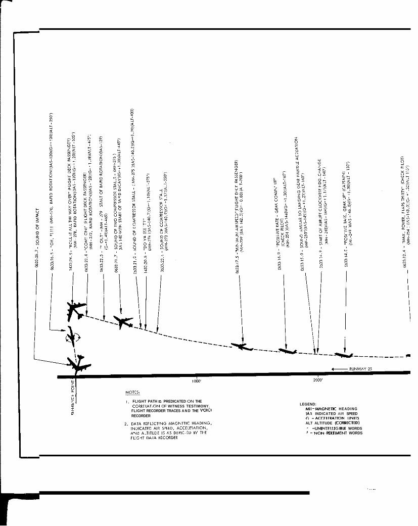
1 . FLIGHT PATH IS PREDICATED ON THE CORRtL/\TION OF WITNESS TESTIMONY.
FLIGHT RECORDER TRACES A N D THE VOICE RECORDER
LEGEND: M H = M A G N E I I C HEADING IAS INDICATED AIR SPEED G =ACCELERATION UNITS ALT ALTITUDE ICORRECTED)
=UNINTELLIGIBLE WORDS X ~ NON-PERTIMENT WORDS

PROFILE VIEW
x i NON-PERTIMENT WORDS ' =UNINTELLIGIBLE WORDS
TIME SCALE FOR PROBABLE FLIGHT PATH 1SECONDSI
n 1 2 3 4 5
Time I C E I ~ not applied dler 0033:22.5
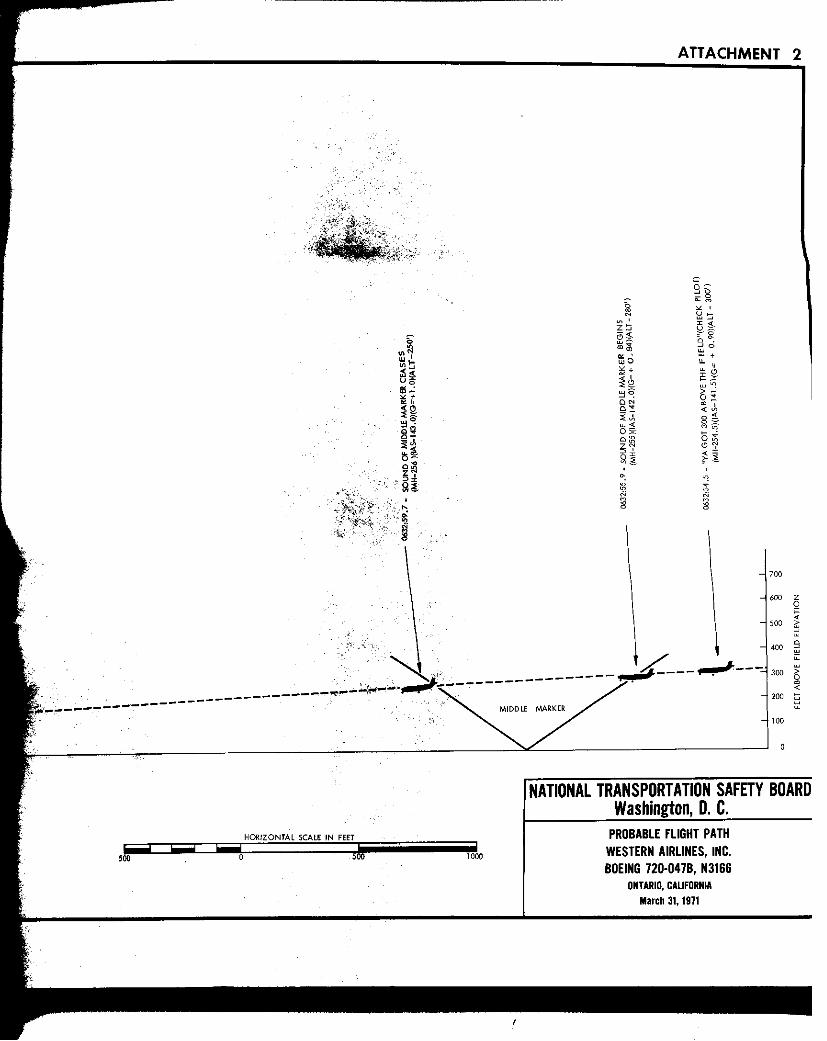

ATTACHMENT 2
HORIZONTAL SCALE IN FEET
500 0 1000
NATIONAL TRANSPORTATION SAFETY BOARD Washington, 0. C.
PROBABLE FLIGHT PATH WESTERN AIRLINES, INC. BOEING 720-0478, N3166
ONTARIO, CALFORNIA March 31, 1971

I
0 ST-I5
D ST-I6
WRECKAGE SITE [Not to Scale]
. . . . . . . ... ,. .
LEGEND: ST 1: Horizontal Stabilizers and to i l c m e sect ST 2: Section of a f t fuselage including the pre' ST 3: Vertical f in and Rudder ST 4: Left wing section from t ip to wing root w ST 5 : Section of outboard pylon ST 6: Section of wing leading edge with sectil
ST'8: Molten wing skin ST 7: Sections of leading edge flaps
ST 9: Sections of fuselage from center section ST IO: Section of f i l l e t flap and fuselage centel ST 11: Section of right f i l le t flap ST 12: Section of inverted fuseloge
ST 14: Section of gal ley ST 13: Right main landing gear
ST 16: Section of lower wing panel ST 15: Section of lower wing panel
ST 17: Section of lower wing panel ST 18: Section of lowerwing panel ST 19: Section of pylon ST 20: Outboad section of r ight aileron S T 21: Trailing edge section of right wing ST 22: Section of outer right wing ST 23: Pylon ST 24: Section of fuselage ST 25: Section of fuselage wi th letter "N" ST 26: Forward baggage comporfment liner
ST 28: Section of fuselage with Indian insignic ST 27: h a t o r y service door
ST 29; Section of fuselage ST 30: Service door assembly, No. 50-7910-9: ST 31: Right autbmrd flap section ST 32: Section of leading edge and leading ed' ST 33: Section of right wing leading edge flae
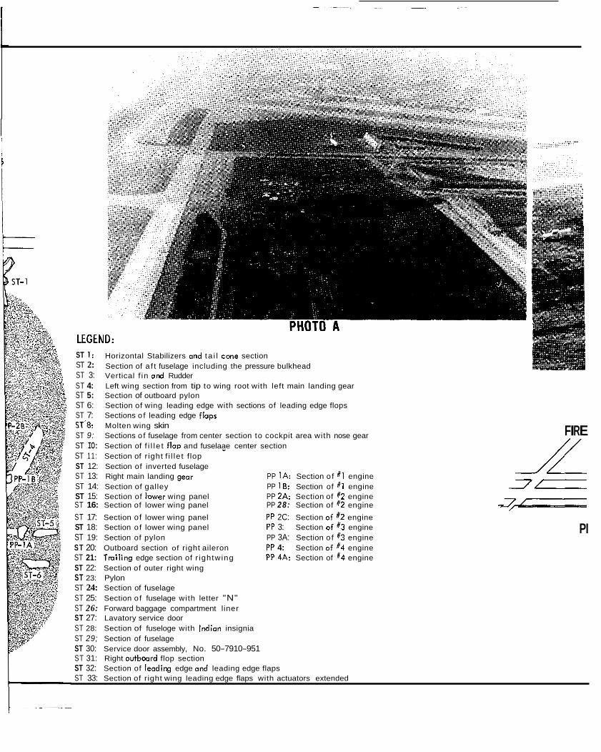
i
LEGE1 ST 1: ST 2: ST 3: ST 4: Left wing section from tip to wing root with left main landing gear ST 5: Section of outboard pylon ST 6: Section of wing leading edge with sections of leading edge flops ST 7: Sections o f leading edge flops ST'8: Molten wing skin ST 9: Sections o f fuselage from center section to cockpit area with nose gear ST IO: Section of f i l l e t flag and fuselaae center section
... ... ;;:::.:... ,,,:::
UD: Horizontal Stabilizers and ta i l c m e section Section of a f t fuselage including the pressure bulkhead Vertical f in and Rudder
FIRE // -
ST 11: Section of r ight f i l le t flop ST 12: Section of inverted fuselage ST 13: Right main landing gear PP I A : Section o f X 1 engine ST 14: Section of galley PP I 8: Section of # I engine -7c ST 15: Section of lower wing panel PP 2A: Section of #2 engine ST 16: Section of lower wing panel PP 28: Section of #2 engine 7 c ST 17: Section of lower wing panel PP 2C: Section o f #2 engine
--7
ST 18: Section o f lower wing panel PP 3: Section o f X3 engine ST 19: Section of pylon PP 3A: Section o f #3 engine ST 20: Outboard section of right aileron PP 4: Section o f #4 engine ST 21: Tmil ing edge section of r ightwing PP 4A: Section of #4 engine ST 22: Section of outer right wing ST 23: Pylon ST 24: Section of fuselage ST 25: Section o f fuselage with letter "N" ST 26: Forward baggage compartment liner ST 27: Lavatory service door ST 28: Section of fuseloge with lmlian insignia ST 29; Section of fuselage ST 30: Service door assembly, No. 50-7910-951 ST 31: Right avtboord flop section ST 32: Section of leoding edge ond leading edge flaps ST 33: Section of right wing leading edge flaps with actuators extended
PI

ATTACHMENT 3
FIRE PERIMETER, PHOTO B /
Iv
NATIONAL TRANSPORTATION SAFETY BOARD Washington, D.C.
I WESTERN AIRLINES, INC. B-720, N 3166 I ONTARIO, CALIFORNIA
March 31, 1971