S7-CPs for Industrial Ethernet - Part A: Configuring and ...ˆ’2 S7-CPs for Industrial Ethernet...
320
Preface, Contents Communication in S7 Stations 1 Characteristics of the Ethernet CPs 2 Commissioning an Ethernet CP 3 SEND/RECEIVE interface 4 Configuring Connections 5 CP as PROFINET IO Controller 6 S7−300 CP as PROFINET IO Device 7 Sending Process Messages by E-Mail 8 File Management and File Access with FTP 9 CP as Web Server: HTML Process Control 10 Web Diagnostics 11 NCM S7 Diagnostics 12 Firmware Loader 13 Appendix A − E / Index SIMATIC NET S7-CPs for Industrial Ethernet Configuring and Commissioning Release 07/2010 C79000−G8976−C182−10 Manual Part A − General Application
Transcript of S7-CPs for Industrial Ethernet - Part A: Configuring and ...ˆ’2 S7-CPs for Industrial Ethernet...

Preface, Contents
Communication in S7 Stations 1
Characteristics of the EthernetCPs 2
Commissioning an Ethernet CP 3
SEND/RECEIVEinterface 4
Configuring Connections 5
CP as PROFINET IO Controller 6
S7−300 CP as PROFINET IODevice 7
Sending Process Messages byE-Mail 8
File Management and FileAccess with FTP 9
CP as Web Server: HTMLProcess Control 10
Web Diagnostics 11
NCM S7 Diagnostics 12
Firmware Loader 13
Appendix A − E / Index
SIMATIC NET
S7-CPs for Industrial EthernetConfiguring and Commissioning
Release 07/2010C79000−G8976−C182−10
ManualPart A − General Application

A−2S7-CPs for Industrial Ethernet Configuring and Commissioning
Release 07/2010
C79000−G8976−C182−10
Classification of Safety−Related Notices
This manual contains notices which you should observe to ensure your ownpersonal safety, as well as to protect the product and connected equipment. Thesenotices are highlighted in the manual by a warning triangle and are marked asfollows according to the level of danger:
!Danger
indicates that death or severe personal injury will result if proper precautions arenot taken.
!Warning
indicates that death or severe personal injury can result if proper precautions arenot taken.
!Caution
with warning triangle indicates that minor personal injury can result if properprecautions are not taken.
Caution
without warning triangle indicates that damage to property can result if properprecautions are not taken.
Notice
indicates that an undesirable result or status can occur if the relevant notice isignored.
Note
highlights important information on the product, using the product, or part of thedocumentation that is of particular importance and that will be of benefit to theuser.

A−3S7-CPs for Industrial Ethernet Configuring and CommissioningRelease 07/2010
C79000−G8976−C182−10
Trademarks
SIMATIC�, SIMATIC HMI� and SIMATIC NET� are registered trademarks ofSIEMENS AG.
Third parties using for their own purposes any other names in this document whichrefer to trademarks might infringe upon the rights of the trademark owners.
Safety Instructions Regarding your Product:
Before you use the product described here, read the safety instructions belowthoroughly.
Qualified Personnel
Only qualified personnel should be allowed to install and work on this equipment.Qualified persons are defined as persons who are authorized to commission, toground, and to tag circuits, equipment, and systems in accordance withestablished safety practices and standards.
Correct Usage of Hardware Products
Note the following
!Warning
This device and its components may only be used for the applications described inthe catalog or the technical description, and only in connection with devices orcomponents from other manufacturers which have been approved orrecommended by Siemens.
This product can only function correctly and safely if it is transported, stored, setup, and installed correctly, and operated and maintained as recommended.
Before you use the supplied sample programs or programs you have writtenyourself, make certain that no injury to persons nor damage to equipment canresult in your plant or process.
EU Directive: Do not start up until you have established that the machine on whichyou intend to run this component complies with the directive 89/392/EEC.
Correct Usage of Software Products
Note the following
!Warning
This software may only be used for the applications described in the catalog or thetechnical description, and only in connection with software products, devices, orcomponents from other manufacturers which have been approved orrecommended by Siemens.
Before you use the supplied sample programs or programs you have writtenyourself, make certain that no injury to persons nor damage to equipment canresult in your plant or process.

A−4S7-CPs for Industrial Ethernet Configuring and Commissioning
Release 07/2010
C79000−G8976−C182−10
Prior to Startup
Before putting the product into operation, note the following warning:
Caution
Prior to startup you must observe the instructions in the relevant documentation.For ordering data of the documentation please refer to the catalogs or contact yourlocal SIEMENS representative.
We have checked the contents of this manual for agreement with thehardware and software described. Since deviations cannot be precludedentirely, we cannot guarantee full agreement. However, the data in thismanual are reviewed regularly and any necessary corrections included insubsequent editions. Suggestions for improvement are welcomed.
Disclaimer of LiabilityCopyright � Siemens AG 2001−2008 All rights reserved
The reproduction, transmission or use of this document or its contents is notpermitted without express written authority. Offenders will be liable fordamages. All rights, including rights created by patent grant or registration ofa utility model or design, are reserved.
Siemens AGIndustry AutomationIndustrial CommunicationPostfach 4848, 90327 Nürnberg Germany Subject to technical change.
Siemens Aktiengesellschaft G79000−G8976−C182−09

A−5S7-CPs for Industrial Ethernet Configuring and CommissioningRelease 07/2010
C79000−G8976−C182−10
This manual...
... supports you when commissioning your SIMATIC NET CP modules in an S7station.
... supports you so that your applications can communicate successfully andefficiently over the SIMATIC NET CPs.
... in tandem with the “Primer” description, provides you with all the information yourequire to implement your communications tasks:
Operating S7 CPs withSTEP 7
Learning from theexample
Installation / commissioning
ManualDescription
“Primer”
Part A� CP overviews
� Communication services
� Network attachment
� Configuration
� Program interface
� Diagnostics� familiarization
� testing interfaces
� commissioning
Part B(device manuals)� Characteristics
� Operator controls/displays
� Operating instructions
� Technical specifications
The description “Primer − NCM S7 for Industrial Ethernet” is in the onlinedocumentation of STEP 7 under “NCM S7 Manuals”. The manual (Part A andPart B) for your S7-CP is in the SIMATIC NET Manual Collection. For details, referto the References in the Appendix.
After installing STEP 7, the examples described in the “Primer” are located in theproject folder for sample programs(<drive>:\Programs\Siemens\Step7\EXAMPLES)!

This manual...
A−6S7-CPs for Industrial Ethernet Configuring and Commissioning
Release 07/2010
C79000−G8976−C182−10
Audience
This manual is intended for personnel responsible for installing and programmingSTEP 7 programs and for service personnel.
Scope of this manual
This manual is valid as of version V5.4 SP4 of the STEP 7 software.
Notice
If functions are described that require higher versions, this is indicated by anadditional icon.
Example:
The description of the IT functions is valid for the following modules:
� 6GK7 343-1GX30-0XE0: as of hardware version 1,as of firmware version V1.0
� 6GK7 443-1GX20-0XE0: as of hardware version 3,as of firmware version V2.0
The term “Advanced CP”
The term “Advanced CP” stands for CP modules with E-mail, FTP or Webfunctions and PROFINET CBA (for example CP x43-1 Advanced).
Structural innovations in the documentation
� The chapter “Programmed Communications Connections“ finden is now in themanual “Functions (FCs) and Function Blocks (FBs) for SIMATIC NET S7 CPs”/10/.

This manual...
A−7S7-CPs for Industrial Ethernet Configuring and CommissioningRelease 07/2010
C79000−G8976−C182−10
New Technical Information / Content
Apart from various adaptations to the currently available devices and the currentversioln of STEP 7 / NCM S7 V5.5, the following changes were made:
� In the Chapter “Configuring Communications Connections”, the information onunspecified connections as it relates to S7 connections was expanded
� The previous name “S5−compatible communication” has been replaced by thename “Open communications services“.
� In the chapter “CP as Web Server: HTML Process Control” it is taken intoaccount that S7 applets can only be generated by individual usw of the suppliedS7 beans; the CP does not provide any preprogrammed specifíc S7 applets.
Note
You should also check the History for this manual in Appendix F.
Notice
Please note that the availability of new functions depends on the device type youare using. You can check which functions your module supports in the descriptionin the Properties dialog in STEP 7 and in the catalog in HW Config.

This manual...
A−8S7-CPs for Industrial Ethernet Configuring and Commissioning
Release 07/2010
C79000−G8976−C182−10
The documentation on the Internet
The following table provides you with an overview of the content and theaddresses for downloading from the Web.
Title Content / Web Addresses
Configuring andCommissioningS7-CPsfor Industrial Ethernet
Configuration ManualPart A
General section:
http://support.automation.siemens.com/WW/view/en/8777865
S7-CPs for IndustrialEthernet
Manual Part B
Device descriptions:
� CP 343-1 Lean (CX00):http://support.automation.siemens.com/WW/view/en/19308657
� CP 343-1 Lean (CX10):http://support.automation.siemens.com/WW/view/en/23643456
� CP 343-1 (EX20/EX11):http://support.automation.siemens.com/WW/view/en/8777308
� CP 343-1 (EX21): http://support.automation.siemens.com/WW/view/en/22259495
� CP 343-1 (EX30):http://support.automation.siemens.com/WW/view/en/24485272
� CP 343-1 PN: http://support.automation.siemens.com/WW/view/en/8776538
� CP 343-1 IT: http://support.automation.siemens.com/WW/view/en/8776544
� CP 343-1 Advanced (GX21):http://support.automation.siemens.com/WW/view/en/22261695
� CP 343-1 Advanced (GX30):http://support.automation.siemens.com/WW/view/en/28017299
� CP 443-1 (EX11):http://support.automation.siemens.com/WW/view/en/8776219
� CP 443-1 (EX20):http://support.automation.siemens.com/WW/view/en/26417141
� CP 443-1 IT: http://support.automation.siemens.com/WW/view/en/8776322
� CP 443-1 Advanced (EX40):http://support.automation.siemens.com/WW/view/en/19308871
� CP 443-1 Advanced (EX41):http://support.automation.siemens.com/WW/view/en/23643789
� CP 443-1 Advanced (GX20):http://support.automation.siemens.com/WW/view/en/28011203
Gateways � IE/PB Link: http://support.automation.siemens.com/WW/view/en/7851748
� IE/PB Link PN IO:http://support.automation.siemens.com/WW/view/en/19299692
� IWLAN/PB Link PN IO:http://support.automation.siemens.com/WW/view/en/21379908

This manual...
A−9S7-CPs for Industrial Ethernet Configuring and CommissioningRelease 07/2010
C79000−G8976−C182−10
Title Content / Web Addresses
NCM S7 for SIMATICNET S7-CPs
Primer
This is available on the Web at:
http://support.automation.siemens.com/WW/view/en/1172503
Commissioning PCStations
Manual and Quick Start
The manual supports you and helps you to make efficient use ofcommunications with your PC applications in conjunction with the SIMATICNET modules. It shows you how to configure PC modules and the stepsrequired in project engineering with NCM S7.
This is available on the Web at:
http://support.automation.siemens.com/WW/view/en/13542666
Configuring andCommissioning S7-CPsfor PROFIBUS
Manual
You will find the Web addresses of the current documents of this manual at theaddress shown below for the Version History.
NCM S7 forPROFIBUS/FMS
This is available on the Web at:
http://support.automation.siemens.com/WW/view/en/1158418
CP documentation in the Manual Collection (order no. A5E00069051)
The SIMATIC NET Manual Collection ships with each S7-CP. This DVD isupdated at regular intervals and contains the latest device manuals anddescriptions available at the time the DVD was written.
Version history/current downloads for the SIMATIC NET S7 CPs
In the “Version History/Current Downloads for the SIMATIC NET S7-CPs”, you willfind information on all previously available CPs for SIMATIC S7 (Ind. Ethernet,PROFIBUS and IE/PB Link).
You will find the latest release of these documents at:
http://support.automation.siemens.com/WW/view/en/9836605
Information on the current block versions (FCs/FBs)
For new user programs, please make sure that you use the latest block versions.You will find information on the current block versions and the current blocks todownload from the Internet at:
http://support.automation.siemens.com/WW/view/en/8797900
If you require replacements, please follow the instructions in the device-specificPart B of this manual.

This manual...
A−10S7-CPs for Industrial Ethernet Configuring and Commissioning
Release 07/2010
C79000−G8976−C182−10
SIMATIC NET Quick Start CD: Samples covering all aspects of communication
The Quick Start CD that can be ordered separately is a treasure-trove ofsample programs and configurations.
You can order this directly over the Internet at:
http://support.automation.siemens.com/WW/view/en/21827955
Additional information on SIMATIC S7 and STEP 7
The additional documentation on the basic software STEP 7 of the SIMATICprogrammable controllers is included in electronic format in your STEP 7installation.
You will also find information on SIMATIC programmable controllers on the QuickStart CD and from the Customer Support Online services at:
http://www.automation.siemens.com/net/index_76.htm
(general information on SIMATIC NET)
or
http://support.automation.siemens.com/WW/view/de
(product information and downloads)

This manual...
A−11S7-CPs for Industrial Ethernet Configuring and CommissioningRelease 07/2010
C79000−G8976−C182−10
Symbols used in this manual
Unless indicated otherwise, the functions described in this manual assume the useof STEP 7. This symbol is used to indicate functions that require a specific versionof STEP 7 or higher, for example Version V5.2.
This symbol appears in the margin to draw your attention to useful tips.
This symbol indicates recommended documentation.
Where you see this symbol, you should also refer to additional information in thebasic help system of STEP 7.
This symbol indicates where detailed context-sensitive help is available. You candisplay these help texts with the F1 key or by clicking on the “Help” button in therelevant dialog.
Conventions
References to other manuals and documentation are indicated by numbers inslashes /.../. These numbers refer to the titles of manuals listed in the Referencessection of the Appendix.
�
F1

Contents
A−12S7-CPs for Industrial Ethernet Configuring and Commissioning
Release 07/2010
C79000−G8976−C182−10
Contents
Contents − Part A
This manual... A−5. . . . . . . . . . . . . . . . . . . . . . . . . . . . . . . . . . . . . . . . . . . . . . . . . . . . . . . . . .
1 Communication via Ethernet CPs in S7 Stations A−19. . . . . . . . . . . . . . . . . . . . . . . . .
1.1 Industrial Ethernet A−20. . . . . . . . . . . . . . . . . . . . . . . . . . . . . . . . . . . . . . . . . . . .
1.2 SIMATIC S7 communication with S7 Ethernet CPs A−21. . . . . . . . . . . . . . . . 1.2.1 Possible types of communication A−21. . . . . . . . . . . . . . . . . . . . . . . . . . . . . . . 1.2.2 The communication services of the Ethernet CPs A−24. . . . . . . . . . . . . . . . . 1.2.3 Operation using a configured or programmed database A−26. . . . . . . . . . . .
1.3 PG/OP communication via Industrial Ethernet A−27. . . . . . . . . . . . . . . . . . . . 1.3.1 PG communication with STEP 7 over Industrial Ethernet A−29. . . . . . . . . . 1.3.2 OP operation: Connecting operator interface devices via
Industrial Ethernet A−30. . . . . . . . . . . . . . . . . . . . . . . . . . . . . . . . . . . . . . . . . . . .
1.4 S7 communication on Industrial Ethernet A−31. . . . . . . . . . . . . . . . . . . . . . . .
1.5 Open communications services (SEND/RECEIVE interface) ) A−36. . . . . .
1.6 FETCH/WRITE services (Server) A−39. . . . . . . . . . . . . . . . . . . . . . . . . . . . . . .
1.7 Networking stations with STEP 7 A−40. . . . . . . . . . . . . . . . . . . . . . . . . . . . . . . 1.7.1 Network/project variant : One subnet, one project A−42. . . . . . . . . . . . . . . . . 1.7.2 Network/project variant: SIMATIC S5 and non-SIMATIC devices
on the subnet A−43. . . . . . . . . . . . . . . . . . . . . . . . . . . . . . . . . . . . . . . . . . . . . . . . 1.7.3 Network/project variant: Two or more subnets, one project A−44. . . . . . . . . 1.7.4 Network/project variant: One subnet, multiple (sub) projects A−45. . . . . . . . 1.7.5 Network/project variant: Multiple subnets in multiple (sub) projects A−48. . 1.7.6 Network/project variant: Connections across subnets (TCP/IP) A−50. . . . . 1.7.7 Network/project variant: IP connection across subnets (TCP/IP) A−51. . . .
2 Characteristics of the Ethernet CPs A−53. . . . . . . . . . . . . . . . . . . . . . . . . . . . . . . . . . . . .
2.1 Communications processors for S7-300 A−53. . . . . . . . . . . . . . . . . . . . . . . . .
2.2 Communications processors for S7-400 A−54. . . . . . . . . . . . . . . . . . . . . . . . .
2.3 Slot rules for SIMATIC S7-300 A−56. . . . . . . . . . . . . . . . . . . . . . . . . . . . . . . . . 2.3.1 Permitted slots A−56. . . . . . . . . . . . . . . . . . . . . . . . . . . . . . . . . . . . . . . . . . . . . . . 2.3.2 Number of SIMATIC NET CPs operated at the same time A−56. . . . . . . . . 2.3.3 Multicomputing A−56. . . . . . . . . . . . . . . . . . . . . . . . . . . . . . . . . . . . . . . . . . . . . . . 2.3.4 Removing/inserting (module replacement) A−57. . . . . . . . . . . . . . . . . . . . . . . 2.3.5 Note on S7-300 CPU: Connection resources A−57. . . . . . . . . . . . . . . . . . . . .
2.4 Slot rules for SIMATIC S7-400 A−58. . . . . . . . . . . . . . . . . . . . . . . . . . . . . . . . . 2.4.1 Permitted slots A−58. . . . . . . . . . . . . . . . . . . . . . . . . . . . . . . . . . . . . . . . . . . . . . . 2.4.2 Number of SIMATIC NET CPs operated at the same time A−58. . . . . . . . . 2.4.3 Multicomputing A−58. . . . . . . . . . . . . . . . . . . . . . . . . . . . . . . . . . . . . . . . . . . . . . . 2.4.4 Removing/inserting (module replacement) A−59. . . . . . . . . . . . . . . . . . . . . . .
Contents
A−13S7-CPs for Industrial Ethernet Configuring and CommissioningRelease 07/2010
C79000−G8976−C182−10
2.4.5 Note on S7-400 CPU: Connection resources A−59. . . . . . . . . . . . . . . . . . . . .
3 Operating the Ethernet CP with STEP 7/NCM S7 A−60. . . . . . . . . . . . . . . . . . . . . . . . . .
3.1 How to commission an Ethernet CP A−61. . . . . . . . . . . . . . . . . . . . . . . . . . . . .
3.2 General information on STEP 7 / NCM S7 A−62. . . . . . . . . . . . . . . . . . . . . . .
3.3 Configuring − how it is done? A−63. . . . . . . . . . . . . . . . . . . . . . . . . . . . . . . . . . 3.3.1 Creating an Industrial Ethernet subnet A−64. . . . . . . . . . . . . . . . . . . . . . . . . . 3.3.2 Entering an Ethernet CP in the hardware configuration A−66. . . . . . . . . . . . 3.3.3 Displaying the network attachments of a station A−69. . . . . . . . . . . . . . . . . .
3.4 Setting further CP properties A−71. . . . . . . . . . . . . . . . . . . . . . . . . . . . . . . . . . . 3.4.1 Addresses tab A−72. . . . . . . . . . . . . . . . . . . . . . . . . . . . . . . . . . . . . . . . . . . . . . . 3.4.2 Options tab A−73. . . . . . . . . . . . . . . . . . . . . . . . . . . . . . . . . . . . . . . . . . . . . . . . . . 3.4.3 Time-of-day Synchronization tab A−76. . . . . . . . . . . . . . . . . . . . . . . . . . . . . . . 3.4.4 Diagnostics tab A−77. . . . . . . . . . . . . . . . . . . . . . . . . . . . . . . . . . . . . . . . . . . . . . 3.4.5 IP Access Protection tab A−77. . . . . . . . . . . . . . . . . . . . . . . . . . . . . . . . . . . . . . 3.4.6 IP Configuration tab A−80. . . . . . . . . . . . . . . . . . . . . . . . . . . . . . . . . . . . . . . . . . 3.4.7 “Port Parameters” tab A−82. . . . . . . . . . . . . . . . . . . . . . . . . . . . . . . . . . . . . . . . . 3.4.8 “PROFINET” tab A−82. . . . . . . . . . . . . . . . . . . . . . . . . . . . . . . . . . . . . . . . . . . . . 3.4.9 Configuring IT functions A−83. . . . . . . . . . . . . . . . . . . . . . . . . . . . . . . . . . . . . . .
3.5 Sending entries for the IP access control list to the CP (Advanced CP) by HTTP A−86. . . . . . . . . . . . . . . . . . . . . . . . . . . . . . . . . . . . . .
3.6 Media Redundancy tab A−88. . . . . . . . . . . . . . . . . . . . . . . . . . . . . . . . . . . . . . . . 3.6.1 Media redundancy options A−88. . . . . . . . . . . . . . . . . . . . . . . . . . . . . . . . . . . . . 3.6.2 Media redundancy in ring topologies A−88. . . . . . . . . . . . . . . . . . . . . . . . . . . . 3.6.3 MRP A−90. . . . . . . . . . . . . . . . . . . . . . . . . . . . . . . . . . . . . . . . . . . . . . . . . . . . . . . . 3.6.4 MRP configuration with PROFINET IO A−92. . . . . . . . . . . . . . . . . . . . . . . . . .
3.7 “Substitute objects” in the STEP 7 project A−95. . . . . . . . . . . . . . . . . . . . . . . .
3.8 Configuring communication services A−98. . . . . . . . . . . . . . . . . . . . . . . . . . . .
3.9 Assigning addresses for the first time A−99. . . . . . . . . . . . . . . . . . . . . . . . . . . 3.9.1 Addressing by selecting the target system in the SIMATIC Manager A−100. 3.9.2 Addressing using the properties dialog in HW Config or NetPro A−101. . . . .
3.10 Downloading the configuration data to the target system A−103. . . . . . . . . . .
4 SEND/RECEIVE Interface in the User Program A−106. . . . . . . . . . . . . . . . . . . . . . . . . . . .
4.1 How the SEND/RECEIVE interface on the CPU works A−107. . . . . . . . . . . .
4.2 Programming the SEND/RECEIVE interface A−109. . . . . . . . . . . . . . . . . . . . .
4.3 Data exchange S7 CPU <−> Ethernet CP A−112. . . . . . . . . . . . . . . . . . . . . . .
4.4 Additional information A−114. . . . . . . . . . . . . . . . . . . . . . . . . . . . . . . . . . . . . . . . . 4.4.1 Programming data transfer on TCP connections A−114. . . . . . . . . . . . . . . . . . 4.4.2 Recommendations for use with a high communications load A−115. . . . . . . .
5 Configuring Communication Connections A−116. . . . . . . . . . . . . . . . . . . . . . . . . . . . . . .
5.1 Procedure A−117. . . . . . . . . . . . . . . . . . . . . . . . . . . . . . . . . . . . . . . . . . . . . . . . . . .
5.2 Possible connection configurations A−118. . . . . . . . . . . . . . . . . . . . . . . . . . . . .
5.3 Connections A−120. . . . . . . . . . . . . . . . . . . . . . . . . . . . . . . . . . . . . . . . . . . . . . . . . 5.3.1 New connection A−122. . . . . . . . . . . . . . . . . . . . . . . . . . . . . . . . . . . . . . . . . . . . . .

Contents
A−14S7-CPs for Industrial Ethernet Configuring and Commissioning
Release 07/2010
C79000−G8976−C182−10
5.3.2 Connections to partners in other projects A−124. . . . . . . . . . . . . . . . . . . . . . . . 5.3.3 Further functions A−126. . . . . . . . . . . . . . . . . . . . . . . . . . . . . . . . . . . . . . . . . . . . . 5.3.4 Connections without assignment A−127. . . . . . . . . . . . . . . . . . . . . . . . . . . . . . .
5.4 Configuring ISO transport connections A−130. . . . . . . . . . . . . . . . . . . . . . . . . . 5.4.1 Specifying the local connection endpoint A−131. . . . . . . . . . . . . . . . . . . . . . . . . 5.4.2 Specifying ISO transport addresses A−133. . . . . . . . . . . . . . . . . . . . . . . . . . . . . 5.4.3 Specifying ISO transport dynamic properties A−136. . . . . . . . . . . . . . . . . . . . . 5.4.4 Checking ISO transport connection properties A−138. . . . . . . . . . . . . . . . . . . .
5.5 Configuring ISO−on−TCP connection properties A−139. . . . . . . . . . . . . . . . . . 5.5.1 Specifying the local connection endpoint A−140. . . . . . . . . . . . . . . . . . . . . . . . . 5.5.2 Specifying ISO−on−TCP addresses A−142. . . . . . . . . . . . . . . . . . . . . . . . . . . . . 5.5.3 Checking ISO−on−TCP connection properties A−145. . . . . . . . . . . . . . . . . . . .
5.6 Configuring TCP connection properties A−146. . . . . . . . . . . . . . . . . . . . . . . . . . 5.6.1 Specifying the local connection endpoint A−147. . . . . . . . . . . . . . . . . . . . . . . . . 5.6.2 Specifying TCP addresses A−149. . . . . . . . . . . . . . . . . . . . . . . . . . . . . . . . . . . . . 5.6.3 Checking TCP connection properties A−153. . . . . . . . . . . . . . . . . . . . . . . . . . . .
5.7 Configuring UDP connection properties A−154. . . . . . . . . . . . . . . . . . . . . . . . . . 5.7.1 Specifying the local connection endpoint A−155. . . . . . . . . . . . . . . . . . . . . . . . . 5.7.2 Specifying UDP addresses A−156. . . . . . . . . . . . . . . . . . . . . . . . . . . . . . . . . . . . 5.7.3 UDP with broadcast and multicast A−160. . . . . . . . . . . . . . . . . . . . . . . . . . . . . . 5.7.4 Checking the properties of a UDP connection A−166. . . . . . . . . . . . . . . . . . . . 5.7.5 Free UDP connection A−167. . . . . . . . . . . . . . . . . . . . . . . . . . . . . . . . . . . . . . . . .
5.8 FETCH/WRITE mode A−168. . . . . . . . . . . . . . . . . . . . . . . . . . . . . . . . . . . . . . . . .
5.9 Routing to distribute load A−171. . . . . . . . . . . . . . . . . . . . . . . . . . . . . . . . . . . . . .
6 CP as PROFINET IO Controller A−172. . . . . . . . . . . . . . . . . . . . . . . . . . . . . . . . . . . . . . . . . .
6.1 Configuration A−173. . . . . . . . . . . . . . . . . . . . . . . . . . . . . . . . . . . . . . . . . . . . . . . . 6.1.1 PROFINET IO system in STEP 7 A−173. . . . . . . . . . . . . . . . . . . . . . . . . . . . . . . 6.1.2 PROFINET IO with IRT communication A−174. . . . . . . . . . . . . . . . . . . . . . . . .
6.2 IO controller mode with S7−300 A−175. . . . . . . . . . . . . . . . . . . . . . . . . . . . . . . . 6.2.1 Programming A−175. . . . . . . . . . . . . . . . . . . . . . . . . . . . . . . . . . . . . . . . . . . . . . . . 6.2.2 Reading and writing data records with FB52 A−176. . . . . . . . . . . . . . . . . . . . . 6.2.3 Interrupt evaluation using FB54 A−176. . . . . . . . . . . . . . . . . . . . . . . . . . . . . . . .
6.3 IO controller mode with S7−400 A−177. . . . . . . . . . . . . . . . . . . . . . . . . . . . . . . . 6.3.1 Multicomputing mode − Assigning the CP to the CPU A−177. . . . . . . . . . . . . 6.3.2 Programming A−177. . . . . . . . . . . . . . . . . . . . . . . . . . . . . . . . . . . . . . . . . . . . . . . .
6.4 Further information on operation with PROFINET IO A−178. . . . . . . . . . . . . . 6.4.1 Effects of multicast communication on RT communication A−178. . . . . . . . .
7 S7−300 CP as PROFINET IO Device A−179. . . . . . . . . . . . . . . . . . . . . . . . . . . . . . . . . . . . . .
7.1 Principle of the data exchange in IO device mode A−180. . . . . . . . . . . . . . . . .
7.2 Configuration A−181. . . . . . . . . . . . . . . . . . . . . . . . . . . . . . . . . . . . . . . . . . . . . . . . 7.2.1 Principle of the IO device coupling A−181. . . . . . . . . . . . . . . . . . . . . . . . . . . . . . 7.2.2 Activating the CP as a PROFINET IO device in the S7 station A−182. . . . . . 7.2.3 Configuring the CP as IO device with IRT communication A−182. . . . . . . . . . 7.2.4 Assigning the PROFINET IO device to a PROFINET IO system A−184. . . .
7.3 Programming A−187. . . . . . . . . . . . . . . . . . . . . . . . . . . . . . . . . . . . . . . . . . . . . . . . 7.3.1 Interface for programming on the PROFINET IO device A−187. . . . . . . . . . .
Contents
A−15S7-CPs for Industrial Ethernet Configuring and CommissioningRelease 07/2010
C79000−G8976−C182−10
7.3.2 Initialization and configuration A−188. . . . . . . . . . . . . . . . . . . . . . . . . . . . . . . . . .
7.4 Example of configuration and programming A−190. . . . . . . . . . . . . . . . . . . . . .
8 Sending Process Messages by E-Mail A−193. . . . . . . . . . . . . . . . . . . . . . . . . . . . . . . . . . .
8.1 Overview of the functions A−193. . . . . . . . . . . . . . . . . . . . . . . . . . . . . . . . . . . . . 8.1.1 Authentication and other features of the Advanced CP A−194. . . . . . . . . . . .
8.2 Configuration A−195. . . . . . . . . . . . . . . . . . . . . . . . . . . . . . . . . . . . . . . . . . . . . . . . 8.2.1 Procedure A−195. . . . . . . . . . . . . . . . . . . . . . . . . . . . . . . . . . . . . . . . . . . . . . . . . . . 8.2.2 Options of mail server mode A−196. . . . . . . . . . . . . . . . . . . . . . . . . . . . . . . . . . . 8.2.3 Configuring a mail server and addressing recipients A−196. . . . . . . . . . . . . . .
8.3 Setting up an E−mail connection A−197. . . . . . . . . . . . . . . . . . . . . . . . . . . . . . .
8.4 Sending an E−mail A−199. . . . . . . . . . . . . . . . . . . . . . . . . . . . . . . . . . . . . . . . . . . 8.4.1 E−mail data block A−199. . . . . . . . . . . . . . . . . . . . . . . . . . . . . . . . . . . . . . . . . . . . 8.4.2 Sending E−mail with AG_SEND/AG_LSEND A−201. . . . . . . . . . . . . . . . . . . . .
8.5 Testing the E-mail function A−202. . . . . . . . . . . . . . . . . . . . . . . . . . . . . . . . . . . .
9 File Management and File Access with FTP A−204. . . . . . . . . . . . . . . . . . . . . . . . . . . . . .
9.1 FTP functions in an S7 station with the Advanced CP A−205. . . . . . . . . . . . .
9.2 Advanced CP as FTP server for the file system on the CP A−206. . . . . . . . . 9.2.1 Method A−206. . . . . . . . . . . . . . . . . . . . . . . . . . . . . . . . . . . . . . . . . . . . . . . . . . . . . 9.2.2 File system − structure and features A−207. . . . . . . . . . . . . . . . . . . . . . . . . . . .
9.3 Advanced CP as FTP server for S7 CPU data A−210. . . . . . . . . . . . . . . . . . . . 9.3.1 Method A−210. . . . . . . . . . . . . . . . . . . . . . . . . . . . . . . . . . . . . . . . . . . . . . . . . . . . . 9.3.2 FTP commands on the FTP client A−211. . . . . . . . . . . . . . . . . . . . . . . . . . . . . . 9.3.3 File allocation table A−213. . . . . . . . . . . . . . . . . . . . . . . . . . . . . . . . . . . . . . . . . . . 9.3.4 Structure of the data blocks (File DB) for FTP services A−218. . . . . . . . . . . .
9.4 The Advanced CP as FTP client for S7 CPU data A−222. . . . . . . . . . . . . . . . 9.4.1 Method A−222. . . . . . . . . . . . . . . . . . . . . . . . . . . . . . . . . . . . . . . . . . . . . . . . . . . . . 9.4.2 Setting up FTP connections A−223. . . . . . . . . . . . . . . . . . . . . . . . . . . . . . . . . . . 9.4.3 Structure of the data blocks (File DB) for FTP services A−225. . . . . . . . . . . . 9.4.4 FCs and FBs for FTP services A−228. . . . . . . . . . . . . . . . . . . . . . . . . . . . . . . . .
10 CP as Web Server: HTML Process Control A−229. . . . . . . . . . . . . . . . . . . . . . . . . . . . . .
10.1 Overview of HTML process control A−229. . . . . . . . . . . . . . . . . . . . . . . . . . . . .
10.2 Security when Accessing Process Data A−231. . . . . . . . . . . . . . . . . . . . . . . . . 10.2.1 Opening ports on the Advanced CP during configuration A−231. . . . . . . . . . . 10.2.2 Operation with firewall and proxy server A−231. . . . . . . . . . . . . . . . . . . . . . . . . 10.2.3 Level of password protection A−232. . . . . . . . . . . . . . . . . . . . . . . . . . . . . . . . . . .
10.3 Accessing the Advanced CP via a Web browser A−233. . . . . . . . . . . . . . . . . .
10.4 Accessing HTML system pages − Examples A−235. . . . . . . . . . . . . . . . . . . . . 10.4.1 Querying the diagnostic buffer A−235. . . . . . . . . . . . . . . . . . . . . . . . . . . . . . . . .
10.5 Creating and storing your own ”home page” A−237. . . . . . . . . . . . . . . . . . . . . .
11 Web Diagnostics A−239. . . . . . . . . . . . . . . . . . . . . . . . . . . . . . . . . . . . . . . . . . . . . . . . . . . . . .
11.1 Initial situation A−239. . . . . . . . . . . . . . . . . . . . . . . . . . . . . . . . . . . . . . . . . . . . . . .
11.2 Setup and operation A−240. . . . . . . . . . . . . . . . . . . . . . . . . . . . . . . . . . . . . . . . . .

Contents
A−16S7-CPs for Industrial Ethernet Configuring and Commissioning
Release 07/2010
C79000−G8976−C182−10
11.3 Diagnostics pages of the CP A−242. . . . . . . . . . . . . . . . . . . . . . . . . . . . . . . . . . . 11.3.1 Start page A−242. . . . . . . . . . . . . . . . . . . . . . . . . . . . . . . . . . . . . . . . . . . . . . . . . . . 11.3.2 Identification A−244. . . . . . . . . . . . . . . . . . . . . . . . . . . . . . . . . . . . . . . . . . . . . . . . . 11.3.3 Rack configuration A−245. . . . . . . . . . . . . . . . . . . . . . . . . . . . . . . . . . . . . . . . . . . . 11.3.4 Diagnostic buffer A−246. . . . . . . . . . . . . . . . . . . . . . . . . . . . . . . . . . . . . . . . . . . . . 11.3.5 Industrial Ethernet A−247. . . . . . . . . . . . . . . . . . . . . . . . . . . . . . . . . . . . . . . . . . . . 11.3.6 PROFINET IO A−250. . . . . . . . . . . . . . . . . . . . . . . . . . . . . . . . . . . . . . . . . . . . . . . 11.3.7 Configured connections A−252. . . . . . . . . . . . . . . . . . . . . . . . . . . . . . . . . . . . . . . 11.3.8 IP access protection A−254. . . . . . . . . . . . . . . . . . . . . . . . . . . . . . . . . . . . . . . . . . 11.3.9 Media redundancy A−255. . . . . . . . . . . . . . . . . . . . . . . . . . . . . . . . . . . . . . . . . . . .
12 NCM S7 Diagnostics A−256. . . . . . . . . . . . . . . . . . . . . . . . . . . . . . . . . . . . . . . . . . . . . . . . . .
12.1 Overview A−257. . . . . . . . . . . . . . . . . . . . . . . . . . . . . . . . . . . . . . . . . . . . . . . . . . . .
12.2 Functions of NCM S7 Diagnostics A−258. . . . . . . . . . . . . . . . . . . . . . . . . . . . . . 12.2.1 Installing and starting NCM S7 Diagnostics A−259. . . . . . . . . . . . . . . . . . . . . . 12.2.2 General menu commands A−261. . . . . . . . . . . . . . . . . . . . . . . . . . . . . . . . . . . . .
12.3 Starting diagnostics A−263. . . . . . . . . . . . . . . . . . . . . . . . . . . . . . . . . . . . . . . . . . . 12.3.1 Establishing a connection to the Ethernet CP A−263. . . . . . . . . . . . . . . . . . . . 12.3.2 Starting diagnostics from the properties dialog of the CP A−263. . . . . . . . . . . 12.3.3 Starting diagnostics from the Windows Start menu A−264. . . . . . . . . . . . . . . . 12.3.4 Using a gateway A−266. . . . . . . . . . . . . . . . . . . . . . . . . . . . . . . . . . . . . . . . . . . . . 12.3.5 Using a PC station − setting a gateway with ”PC internal” A−269. . . . . . . . . . 12.3.6 Other ways of starting diagnostics A−270. . . . . . . . . . . . . . . . . . . . . . . . . . . . . .
12.4 How to use diagnostics A−271. . . . . . . . . . . . . . . . . . . . . . . . . . . . . . . . . . . . . . . .
12.5 Starting diagnostic functions explicitly A−272. . . . . . . . . . . . . . . . . . . . . . . . . . .
12.6 Checklist for ‘typical problems‘ in a system A−274. . . . . . . . . . . . . . . . . . . . . . . 12.6.1 Checklist for general CP functions A−274. . . . . . . . . . . . . . . . . . . . . . . . . . . . . . 12.6.2 Communication connection checklist A−275. . . . . . . . . . . . . . . . . . . . . . . . . . . .
12.7 Diagnostic messages from E−mail connections with authentication A−276. .
13 Firmware Loader A−278. . . . . . . . . . . . . . . . . . . . . . . . . . . . . . . . . . . . . . . . . . . . . . . . . . . . . .
13.1 Area of application A−278. . . . . . . . . . . . . . . . . . . . . . . . . . . . . . . . . . . . . . . . . . . .
13.2 Loading firmware A−279. . . . . . . . . . . . . . . . . . . . . . . . . . . . . . . . . . . . . . . . . . . . .
A Connector Pinning A−281. . . . . . . . . . . . . . . . . . . . . . . . . . . . . . . . . . . . . . . . . . . . . . . . . . . . .
A.1 24 V DC connector A−281. . . . . . . . . . . . . . . . . . . . . . . . . . . . . . . . . . . . . . . . . . .
A.2 RJ-45 jack for twisted−pair Ethernet A−281. . . . . . . . . . . . . . . . . . . . . . . . . . . .
A.3 Connector for Industrial Ethernet A−282. . . . . . . . . . . . . . . . . . . . . . . . . . . . . . .
A.4 Connector for PROFIBUS A−283. . . . . . . . . . . . . . . . . . . . . . . . . . . . . . . . . . . . .
B Standards and approvals of SIMATIC NET S7 CPs A−284. . . . . . . . . . . . . . . . . . . . . . . .
C References and Literature A−290. . . . . . . . . . . . . . . . . . . . . . . . . . . . . . . . . . . . . . . . . . . . . .
D Glossary A−296. . . . . . . . . . . . . . . . . . . . . . . . . . . . . . . . . . . . . . . . . . . . . . . . . . . . . . . . . . . . . .
D.1 General section A−296. . . . . . . . . . . . . . . . . . . . . . . . . . . . . . . . . . . . . . . . . . . . . .
D.2 Industrial Ethernet and IT functions of the CPs A−300. . . . . . . . . . . . . . . . . . .
D.3 PROFINET A−305. . . . . . . . . . . . . . . . . . . . . . . . . . . . . . . . . . . . . . . . . . . . . . . . . .

Contents
A−17S7-CPs for Industrial Ethernet Configuring and CommissioningRelease 07/2010
C79000−G8976−C182−10
E Linking to Other Systems with FETCH/WRITE A−307. . . . . . . . . . . . . . . . . . . . . . . . . . .
F Document History A−312. . . . . . . . . . . . . . . . . . . . . . . . . . . . . . . . . . . . . . . . . . . . . . . . . . . . . .

A−18S7-CPs for Industrial Ethernet Configuring and Commissioning
Release 07/2010
C79000−G8976−C182−10

A−19S7-CPs for Industrial Ethernet Configuring and CommissioningRelease 07/2010
C79000−G8976−C182−10
1 Communication via Ethernet CPs in S7Stations
The Ethernet CP for SIMATIC S7 provides a series of communications services fordifferent tasks.
This chapter explains the following:
� The types of communication possible with the Ethernet CP on IndustrialEthernet
� The tasks handled by the Ethernet CP for the various services
� How to create the conditions for your communications requirements
You will find further information in the following sources:
� When installing the Ethernet CP, follow the instructions in the manual in theManual Collection that ships with the Ethernet CP /1/. This also contains furtherinformation about the performance of the Ethernet CP .
� For the functions and use of the STEP 7 configuration software, some of whichis used to configure the CP (such as hardware configuration), please refer to/6/.

1 Communication via Ethernet CPs in S7 Stations
A−20S7-CPs for Industrial Ethernet Configuring and Commissioning
Release 07/2010
C79000−G8976−C182−10
1.1 Industrial Ethernet
Definition
Within the open, heterogeneous SIMATIC NET communication system, IndustrialEthernet is the network for the management and cell level. Physically, IndustrialEthernet is an electrical network that uses a shielded coaxial cable or twisted pairor an optical network with fiber-optic cables.
Industrial Ethernet is defined by the international standard IEEE 802.3.
All-round communication in the industrial sector
Industrial Ethernet is integrated in the SIMATIC NET concept that allowscomprehensive networking of the management, cell and field levels along withPROFINET / PROFIBUS and the AS-Interface (AS-i).
PROFIBUS (EN 50170 Vol. 2 PROFIBUS)
AS-Interface(AS-i, Actuator-SensorInterface)
Industrial Ethernet
(IEEE 802.3)
PROFINET
Figure 1-1 Industrial Ethernet in the SIMATIC NET concept
Network access
Industrial Ethernet is accessed using the CSMA/CD (Carrier Sense MultipleAccess with Collision Detection) network access technique specified inIEEE 802.3.

1 Communication via Ethernet CPs in S7 Stations
A−21S7-CPs for Industrial Ethernet Configuring and CommissioningRelease 07/2010
C79000−G8976−C182−10
1.2 SIMATIC S7 communication with S7 Ethernet CPs
1.2.1 Possible types of communication
The Ethernet CP for SIMATIC S7 supports the following types of communicationdepending on the CP type:
Possible types of communicationInterfaces / Services /Protocols
S7-300S7-400
� PG/OP communication
� S7 communication
with the protocols
− ISO Transport
− ISO-on-TCP (TCP/IP with RFC 1006)
� S5-compatible communication
� PROFINET IO and PROFINET CBA
� HTML process control withweb browser
� File management and fileaccess with FTP
with the SEND / RECEIVE interface and the protocols
− ISO Transport
− ISO-on-TCP (TCP/IP with RFC 1006)
− TCP
− UDP
with FETCH / WRITE services and the protocols
− ISO Transport
− ISO-on-TCP (TCP/IP with RFC 1006)
− TCP
with the protocols
− TCP
− UDP
− RT (PROFINET IO and CBA)
− IRT (PROFINET IO)
− DCOM (PROFINET CBA)
with the protocols
− HTTP / IP protocol
with the protocols
− FTP / IP protocol
Ethernet CPEthernet CP
� E-mail communication with the protocols
− SMTP / ESMTP

1 Communication via Ethernet CPs in S7 Stations
A−22S7-CPs for Industrial Ethernet Configuring and Commissioning
Release 07/2010
C79000−G8976−C182−10
� PG/OP communication
PG/OP communication is used to download programs and configuration data,to run tests and diagnostic functions, and to control and monitor a plant fromOPs.
� S7 communication
S7 communication forms a simple and efficient interface between SIMATIC S7stations and PGs/PCs using communication function blocks.
� Open communications services with SEND/RECEIVE interface
Depending on the CP type, the SEND/RECEIVE interface allowsprogram-controlled communication on a configured connection from a SIMATICS7 PLC to another SIMATIC S7 PLC, to a SIMATIC S5 PLC, to PCs/PGs, andto any other station.
Depending on the CP type, the following communications services are availableon the SEND/RECEIVE interface:
− ISO Transport
optimized for top performance at the self-contained manufacturing level
− IP−based services for internetwork communication with
ISO-on-TCP connections (RFC 1006), TCP connections and
UDP datagram service (including broadcast / multicast).
� S5-compatible communication with FETCH/WRITE services (server)
The FETCH/WRITE services (server) allow direct access to the systemmemory areas on the SIMATIC S7 CPU from SIMATIC S5, SIMATIC PCstations, or from devices of other ranges.
Depending on the CP type, the following communications services are availablefor FETCH/WRITE access:
− ISO Transport
optimized for top performance at the self-contained manufacturing level
− TCP/IP for internetwork communication with
ISO-on-TCP connections (RFC 1006), TCP connections.
� PROFINET IO
PROFINET is a standard of the PROFIBUS Users organization defining aheterogeneous communications and engineering model.
− PROFINET IO controller
The S7-CPs that support the PROFINET IO controller mode allow directaccess to IO devices over Industrial Ethernet.
− PROFINET IO device
With the S7-CPs that support the PROFINET IO device mode, you canoperate S7 stations as “intelligent” PROFINET IO devices on IndustrialEthernet.
For more detailed information on PROFINET CBA, refer to /16/ and /15/

1 Communication via Ethernet CPs in S7 Stations
A−23S7-CPs for Industrial Ethernet Configuring and CommissioningRelease 07/2010
C79000−G8976−C182−10
For PROFINET IO communication, TCP connections are used to assignparameters and RT (real time) or IRT (isochronous real time) for cyclic IO datatraffic.
� PROFINET CBA
An S7 station equipped with a CP capable of PROFINET CBA can beinterconnected as a PROFINET CBA component in SIMATIC iMap.
For more detailed information on PROFINET CBA, refer to /8/
In PROFINET CBA, interconnections are used with acyclic and cyclictransmission.
� HTML process control
With some CPs (for example Advanced CPs), use the supplied functions andHTML pages to query important system data using a Web browser (seeChapter 10).
� File management and file access with FTP
The CPs with IT functionality (S7-400 / S7-300) provide additional functions forFTP services.
You can use your S7 station both as an FTP client and as an FTP server (seeChapter 9).
− S7 Station as FTP Client
You can transfer data blocks from or to a file server.
− S7 Station as FTP Server
Another station, for example, a PC transfers data blocks to or from the S7station the file system on the CP with IT functionality.
� E-mail communication
CPs with IT functions provide E-mail services.
This allows the controller to send messages dependent on process events (seeChapter 8).
1 Communication via Ethernet CPs in S7 Stations
A−24S7-CPs for Industrial Ethernet Configuring and Commissioning
Release 07/2010
C79000−G8976−C182−10
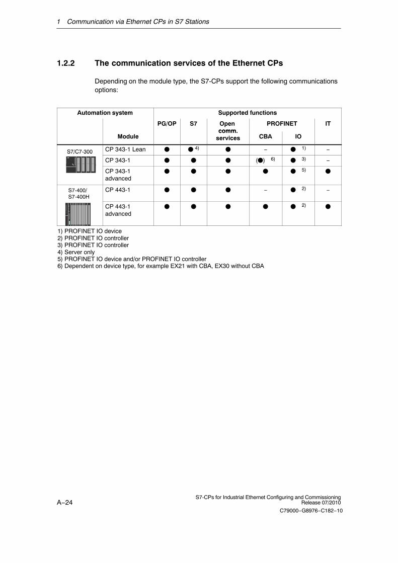
1.2.2 The communication services of the Ethernet CPs
Depending on the module type, the S7-CPs support the following communicationsoptions:
Automation system Supported functions
PG/OP S7 Open comm
PROFINET IT
Modulecomm.
services CBA IO
S7/C7-300 CP 343-1 Lean � � 4) � − ��1) −S7/C7 300
CP 343-1 � � � (�)�6) ��3) −
CP 343-1advanced
� � � � ��5) �
S7-400/S7-400H
CP 443-1 � � � − ��2) −
CP 443-1advanced
� � � � ��2) �
1) PROFINET IO device2) PROFINET IO controller3) PROFINET IO controller4) Server only5) PROFINET IO device and/or PROFINET IO controller6) Dependent on device type, for example EX21 with CBA, EX30 without CBA
1 Communication via Ethernet CPs in S7 Stations
A−25S7-CPs for Industrial Ethernet Configuring and CommissioningRelease 07/2010
C79000−G8976−C182−10
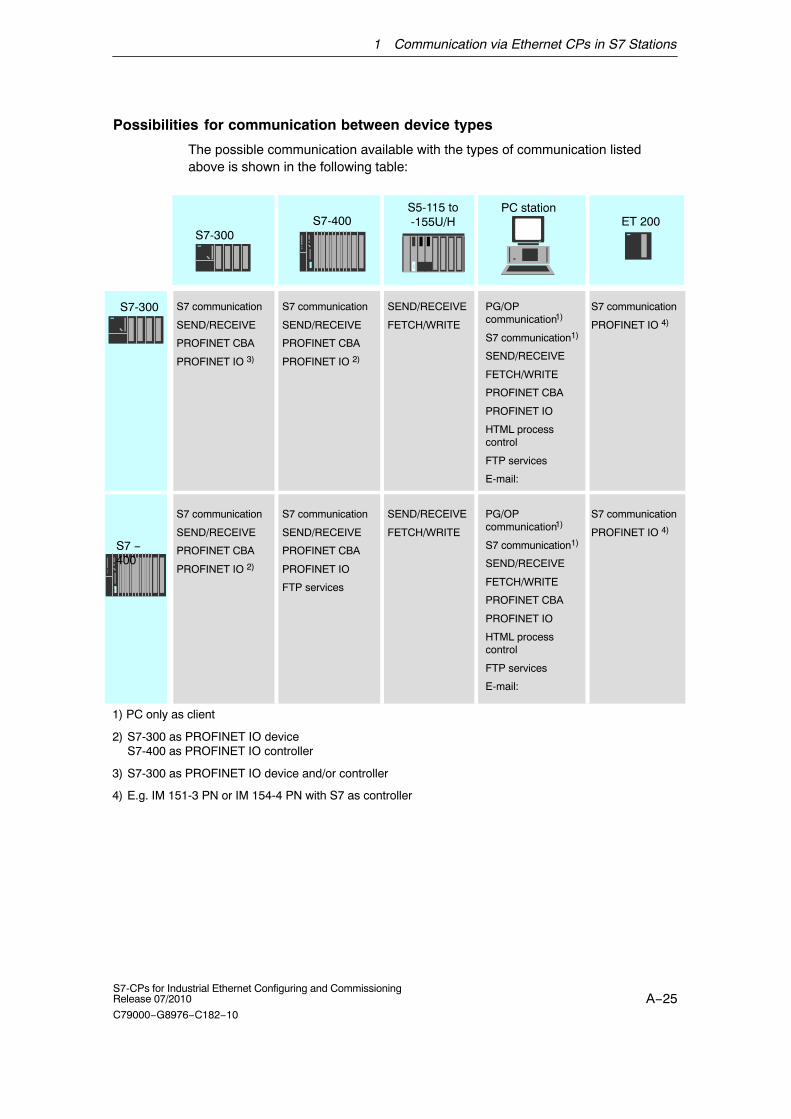
Possibilities for communication between device types
The possible communication available with the types of communication listedabove is shown in the following table:
S7-300
S5-115 to-155U/HS7-400
PC station
S7-300
S7 −400
SEND/RECEIVE
FETCH/WRITE
PG/OP communication1)
S7 communication1)
SEND/RECEIVE
FETCH/WRITE
PROFINET CBA
PROFINET IO
HTML processcontrol
FTP services
E-mail:
S7 communication
SEND/RECEIVE
PROFINET CBA
PROFINET IO 3)
1) PC only as client
2) S7-300 as PROFINET IO deviceS7-400 as PROFINET IO controller
3) S7-300 as PROFINET IO device and/or controller
4) E.g. IM 151-3 PN or IM 154-4 PN with S7 as controller
PG/OP communication1)
S7 communication1)
SEND/RECEIVE
FETCH/WRITE
PROFINET CBA
PROFINET IO
HTML processcontrol
FTP services
E-mail:
S7 communication
SEND/RECEIVE
PROFINET CBA
PROFINET IO 2)
SEND/RECEIVE
FETCH/WRITE
S7 communication
SEND/RECEIVE
PROFINET CBA
PROFINET IO
FTP services
S7 communication
SEND/RECEIVE
PROFINET CBA
PROFINET IO 2)
ET 200
S7 communication
PROFINET IO 4)
S7 communication
PROFINET IO 4)

1 Communication via Ethernet CPs in S7 Stations
A−26S7-CPs for Industrial Ethernet Configuring and Commissioning
Release 07/2010
C79000−G8976−C182−10
1.2.3 Operation using a configured or programmed database
Configuration and diagnostics
The STEP 7 or NCM S7 configuration software is required to connect andconfigure the Ethernet CP.
NCM S7 provides a wide range of diagnostic functions for the various types ofcommunication with Industrial Ethernet.
NCM S7 is installed automatically with STEP 7 and is therefore integrated in STEP7.
When configuring PROFINET CBA communication, you also use the engineeringtool SIMATIC iMap; for detailed information on SIMATIC iMap, refer to the manualComponent based Automation − Configuring Plants with SIMATIC iMap /8/.
Programmed communication connections
In some situations, it is an advantage to set up communication connections notover the configuration interface of STEP 7 but program-controlled by specificapplications.
Function block FB55 IP_CONFIG is available for these applications and allowsflexible transfer of data blocks with configuration data to an Ethernet CP. Forinformation on the interfaces of the CP for which this is possible, refer to themanual of the relevant device.
1 Communication via Ethernet CPs in S7 Stations
A−27S7-CPs for Industrial Ethernet Configuring and CommissioningRelease 07/2010
C79000−G8976−C182−10
1.3 PG/OP communication via Industrial Ethernet
Application
PG/OP communication provides functions that are already integrated in everySIMATIC S7/M7/C7 device.
A distinction must be made between the following two types of function:
� PG communication
PG communication with STEP 7 PLCs on Industrial Ethernet means thefollowing:
− You can use the complete range of functions of STEP 7 on IndustrialEthernet.
− You can use programming, diagnostic, operating and monitoring functions onall modules in the SIMATIC S7 PLC via Industrial Ethernet.
� OP Operation
PG/OP communication on Industrial Ethernet allows the operation andmonitoring of all modules in a SIMATIC S7 PLC using operator interfacesystems (TD/OP).
The Ethernet CP acts as a “communications relay” that relays the PG/OPcommunication via Industrial Ethernet.
The following schematic illustrates how PG/OP communication can be used locallyor remotely:
� Local over Ethernet modules in the PG
� Remote over Ethernet modules in the PG and over routers; (the option of a PG-PLC remote link with TeleService over a TS adapter is alsoshown)

1 Communication via Ethernet CPs in S7 Stations
A−28S7-CPs for Industrial Ethernet Configuring and Commissioning
Release 07/2010
C79000−G8976−C182−10
Ind. Ethernet
S7 − 300
Create configuration data forevery CP and download to theEthernet CPs
STEP 7NCM S7
S7 − 400
Ethernet CP
Ethernet attachment
* over TCP/IP
Modem / ISDN
WAN *
Ethernet CP
PC with Ethernet CP
OperatorInterfacefunctions
OP
S7 − 400
Ethernet CP
Router (for exampleISDN)
Router (for exampleISDN)
Ind. Ethernet
TS adapter
Modem / ISDN
Figure 1-2 Configuration for PG/OP operation − local and remote

1 Communication via Ethernet CPs in S7 Stations
A−29S7-CPs for Industrial Ethernet Configuring and CommissioningRelease 07/2010
C79000−G8976−C182−10
1.3.1 PG communication with STEP 7 over Industrial Ethernet
Requirements for PG communication
PG communication is possible when the following requirements are met:
� An Ethernet CP is installed in the PG or engineering station or there is amodem/ISDN interface for remote access.
� The Ethernet CP must have an address (default MAC address or set the IPaddress).
With CPs that have several independent interfaces, for example 1 PROFINETinterface and 1 gigabit interface, you can connect your PG or engineering station tothe gigabit interface when networking the PROFINET interface with your plant. Youcan access the subnet of one interface from the other interface.
Networking the PG / engineering station
Depending on the configuration of the PG or Engineering Station, the following twosituations are possible when using PG communication:
� PG / Engineering Station in the Configured Mode
If you select this configuration when you commission the PG / engineeringstation, the interfaces of the communication modules you are using are alreadyknown. The option in “Set PG/PC Interface” is automatically set to“PC-internal”.
Once you have downloaded this configuration to your PG / engineering station,you can exchange PG functions with the accessible nodes in the network withSTEP 7 without requiring any further settings.
� PG / engineering station in PG operation
If your PG or engineering station is configured for this mode, you must specify theinterface on the PG or engineering station explicitly with “Set PG/PC Interface”.
Follow the steps outlined below:
1. Open the “Set PG/PC Interface” dialog box in the Windows Control Panel.
2. Set the PG/PC interface according to the CPs available on your PG andaccording to the bus attachment (interface parameter assignment used).
For more detailed information on the topic of PG operation and engineering station,refer to /5/.

1 Communication via Ethernet CPs in S7 Stations
A−30S7-CPs for Industrial Ethernet Configuring and Commissioning
Release 07/2010
C79000−G8976−C182−10
1.3.2 OP operation: Connecting operator interface devices viaIndustrial Ethernet
Requirements
Operation allowing operator interface functions is possible when the followingconditions are met:
� The following are installed in the operator control and monitoring device:
− an Ethernet CP
− SOFTNET S7 for Ind. Ethernet or software from the SIMATIC NET CD.
� The CPs in the S7 stations are supplied with a MAC/IP address (use the defaultMAC address or set an IP address).
With CPs that have several independent interfaces, for example 1 PROFINETinterface and 1 gigabit interface, you can connect your PG or engineering station tothe gigabit interface when networking the PROFINET interface with your plant. Youcan access the subnet of one interface from the other interface.
Procedure
To be able to use S7 communication, address the required module in the SIMATICS7 PLC on your operator interface system.
For more detailed information, please refer to the description of your operatorcontrol and monitoring devices and in /5/.

1 Communication via Ethernet CPs in S7 Stations
A−31S7-CPs for Industrial Ethernet Configuring and CommissioningRelease 07/2010
C79000−G8976−C182−10
1.4 S7 communication on Industrial Ethernet
Application
S7 communication via Industrial Ethernet allows program-controlledcommunication using communication SFBs/FBs via configured S7 connections.Per job, up to 64 Kbytes of user data can be transmitted.
The Ethernet CP acts as an “S7 communication relay” by passing on the S7functions via Industrial Ethernet. Depending on the configuration of the EthernetCP, data transfer is on the basis of the ISO transport or the ISO-on-TCP protocol(TCP/IP with RFC 1006).
From a user perspective, S7 communication via PROFIBUS and IndustrialEthernet is identical.

1 Communication via Ethernet CPs in S7 Stations
A−32S7-CPs for Industrial Ethernet Configuring and Commissioning
Release 07/2010
C79000−G8976−C182−10
Nodes
Two situations must be distinguished depending on device type and plantconfiguration:
� Client and server functionality at both ends
S7 connections can be operated between the following nodes with the entirefunctionality of S7 communication:
− between S7 stations S7-300 and S7-400;
− between S7 stations and PC/PG stations with an Ethernet CP.
Ethernet
PC/PG with Ethernet CP
S7 − 400S7 − 300
Ethernet CP
M7
* only TCP/IP
S7 - 300 / 400
Ethernet CP
PUT / GETBSEND / BRECVUSEND / URECVWAN *
Figure 1-3 Nodes communicating on S7 connections over Industrial Ethernet

1 Communication via Ethernet CPs in S7 Stations
A−33S7-CPs for Industrial Ethernet Configuring and CommissioningRelease 07/2010
C79000−G8976−C182−10
� Client and server functionality at one end only (S7 connectionsconfigured at one end)
In the following situations, write and read functions can be implemented withPUT / GET on one-ended S7 connections:
− S7 communication over router
PG/PC stations can access S7 stations if the PG/PC stations are connectedto a different subnet or subnet type (PROFIBUS / Ethernet) via routers (forexample, an IE/PB Link); in this case, S7 stations are servers.
S7 communication is possible over a gateway.
Ethernet
PROFIBUS
IE/PB Link
PC/PG Station
S7 − 400S7 − 300Ethernet CP Ethernet CP
PUT / GET
Ethernet
PUT / GET
PC/PG Station
Figure 1-4 PC/PG station communicates over a gateway with S7 stations on an underlying PROFIBUSor Ethernet
For more detailed information on the features supported by your Ethernet CP, referto the device-specific part of this manual /1/.

1 Communication via Ethernet CPs in S7 Stations
A−34S7-CPs for Industrial Ethernet Configuring and Commissioning
Release 07/2010
C79000−G8976−C182−10
Configuring S7 connections
Create S7 connections to use S7 communication for data exchange between twoSIMATIC S7 stations.
For more detailed information, refer to the STEP 7 Description /6/.
Notice
S7 connections via routers are supported only within a STEP 7 project but notbetween partners in different STEP 7 projects of a multiproject!
Interface in the user program of the S7 station
You use SFBs (for S7-400) and FBs (for S7-300) in the user program.
Block type Client Server Described in
SFB / FB12 BSEND x − STEP 7D t ti /23/
SFB / FB13 BRCV xDocumentation /23/
SFB / FB15 PUT x − 1)
SFB / FB14 GET x − 1)
SFB / FB8 USEND x −
SFB / FB9 URCV − x
SFC / FC62 CONTROL (S7-400) /C_CNTRL (S7-300)
x x 2)
1) you do not need to configure a connection on the server
2) for S7-300
Notice
Please remember the following points regarding data consistency in your userprogram:
In the CPU of the S7 station, the read or written information is taken from the S7user program into the operating system or copied from the operating system to theS7 user program in blocks of 8 or 32 bytes (depending on the firmware version).
If information in the word or double-word format is located across suchboundaries, data inconsistency may arise during transmission using S7communication!
For more detailed information, refer to the STEP 7 documentation /23/.

1 Communication via Ethernet CPs in S7 Stations
A−35S7-CPs for Industrial Ethernet Configuring and CommissioningRelease 07/2010
C79000−G8976−C182−10
Notes on S7 communication between PC/PG station and S7 station
Applications in a PC/PG station communicate with the S7 station over an OPCinterface or SAPI-S7 interface for operator intervention, monitoring and control.
The S7 stations use the integrated communication SFBs/FBs (client and serverfunctionality at both ends).
The following general requirements must be met by a PC/PG station for S7communication:
� The following are installed in the PC/PG:
− an Ethernet CP
− an interface for S7 communication: SOFTNET S7 for Industrial Ethernet orsoftware from the SIMATIC NET CD.
� The CPs in the S7 stations are supplied with a MAC/IP address (use the defaultMAC address or set an IP address).
To use S7 communication with the SIMATIC S7 PLC from a PC, address therequired CPU module in the SIMATIC S7 PLC that you want to communicate within your PC application.
S7 communication via routers (one-ended client and server functionality)
It is possible to reach the S7 station from an application (OPC server) of thePC/PG station that is attached to another subnet. The subnets must be connectedover a router such as the IE/PB Link. An S7 station or a PC connected to bothsubnets can also serve as a router.
In this configuration, the S7 station can only be addressed by the PC/PG station asa communications server on S7 connections configured at one end.
The requirements for the configuration of the PC/PG station are identical to thosefor operation in the same subnet (see above); the CP in the PC/PG station mustalso have routing capability.
In this situation, configure a one-ended S7 connection to the PC/PG station in theother subnet for the PC/PG station in STEP 7 NetPro. You can then read and writedata in the S7 station in your user program using the services for S7communication
Connection of a PG/PC to an S7 station via a CP with 2 interfaces
To access a PG/PC on the PROFINET subnet to which an S7 station is connected,you can use a CP with two interfaces in the S7 station, for example an AdvancedCP with PROFINET and gigabit interface. When connecting the PC/PG (forexample as an operator control and monitoring device) to the gigabit interface ofthe CP, you can access the subnet on the PROFINET interface of the CP via theintegrated switch of the CP.

1 Communication via Ethernet CPs in S7 Stations
A−36S7-CPs for Industrial Ethernet Configuring and Commissioning
Release 07/2010
C79000−G8976−C182−10
1.5 Open communications services (SEND/RECEIVEinterface) 1)
Application
Using the SEND/RECEIVE interface, your S7 user program has access to opencommunications services with configured connections.
Data transmission over a configured connection is suitable for the following typesof transmission:
� the reliable transmission of related blocks of data between two Ethernet nodesusing
− TCP or ISO-on-TCP connection;
− ISO transport connection (not for PROFINET CBA standard components).
� simple (unacknowledged) transfer of related blocks of data (datagram service)between two Ethernet nodes with UDP (User Datagram Protocol) on IP.
The SEND/RECEIVE interface is also used for sending E-mail (see Chapter 7).
ISO transport connection
ISO transport provides services for the reliable transfer of data on configuredconnections. Due to segmentation (packet-oriented segmentation − thecompleteness of the message is detected) large amounts of data can betransmitted.
Transmission reliability is extremely high due to automatic repetition and additionalfield check mechanisms. The communications partner confirms reception of dataand the sender receives a return value on the SEND/RECEIVE interface.
ISO transport is operated only on Industrial Ethernet and is optimized forhigh-performance operation at the self-contained manufacturing level.
1 The previous name of the SEND/RECEIVE interface was S5S5 connections
1 Communication via Ethernet CPs in S7 Stations
A−37S7-CPs for Industrial Ethernet Configuring and CommissioningRelease 07/2010
C79000−G8976−C182−10
IP (Internet Protocol)
For internetwork data transmission, the following services are available withsuitable CPs such as the CP 443-1:
� ISO-on-TCP connection
ISO-on-TCP is intended for reliable, internetwork data transmission.
The ISO-on-TCP service corresponds to the TCP/IP standard (TransmissionControl Protocol/Internet Protocol) with the RFC 1006 extension according tolayer 4 of the ISO reference model (see /9/).
RFC 1006 extends the TCP protocol by allowing the transmission of blocks ofdata (“messages”) assuming that both partners support RFC 1006.
Transmission reliability is extremely high due to automatic repetition andadditional field check mechanisms. The communications partner confirmsreception of data and the sender receives a return value on theSEND/RECEIVE interface.
� TCP connection
When using the SEND/RECEIVE interface on TCP connections, the EthernetCP supports the socket interface (for example, Winsock.dll) to TCP/IP found onalmost every system (PC or other system).
TCP is intended for reliable internetwork data transmission.
The TCP service complies with the TCP/IP standard (Transmission ControlProtocol/Internet Protocol; see /9/).
� UDP connection
UDP is intended for simple internetwork data transmission without confirmation.
If the connection is suitably configured, broadcast and multicast frames canalso be sent on UDP connections.
To avoid overload due to high broadcast load, the CP does not allow receptionof UDP broadcasts. As an alternative, use the multicast function over a UDPconnection. This allows you to register the CP as a node in a multicast group.
SEND/RECEIVE interface
Data transfer is triggered by the user program. The interface to the user program inthe SIMATIC S7 is formed by special SIMATIC S7 blocks of the type FC(functions).

1 Communication via Ethernet CPs in S7 Stations
A−38S7-CPs for Industrial Ethernet Configuring and Commissioning
Release 07/2010
C79000−G8976−C182−10
Stations
The SEND/RECEIVE interface allows program-controlled communication onIndustrial Ethernet between the SIMATIC S7 PLC and the following:
� SIMATIC S7 PLC with Ethernet CP
� SIMATIC S5 PLC with Ethernet CP
� PC/PG with Ethernet CP
� Stations with Ethernet attachment
Ethernet
PG/PC with Ethernetattachment
SIMATIC S5 with Ethernet CP
S7 − 300S7 − 400Ethernet CP
Other station with Ethernet attachment
WAN Internet only TCP/IP
Router
Ethernet CP
Figure 1-5 SIMATIC S7 PLC with possible communications partners on the SEND/RECEIVE interface
1 Communication via Ethernet CPs in S7 Stations
A−39S7-CPs for Industrial Ethernet Configuring and CommissioningRelease 07/2010
C79000−G8976−C182−10
1.6 FETCH/WRITE services (Server)
Application
In addition to the SEND/RECEIVE interface, the FETCH/WRITE functionalityprovides further services for open communications services on configuredtransport connections.
The FETCH/WRITE interface is used primarily to attach SIMATIC S7 toSIMATIC S5 and to other non-S7 stations (for example PCs).
� FETCH
The partner on the connection (SIMATIC S5 or non-S7 station) can readsystem data on the SIMATIC S7 PLC.
� WRITE
The partner on the connection (SIMATIC S5 or non-S7 station) can writesystem data on the SIMATIC S7 PLC.
From the point of view of the SIMATIC S7 PLC, this is a passive communicationfunction that simply needs to be configured, the communications partner initiatesthe connection establishment.
For further information, refer to the system documentation of the SIMATIC S5 PLCor the non-S7 station you are using.
Connection types
To access a station with FETCH or WRITE functions, a FETCH passive or WRITEpassive connection must be configured. The following types are possible:
� ISO Transport
� ISO-on-TCP
� TCP
Coordinating access using the user program
You can use the FCs AG_LOCK and AG_UNLOCK to coordinate access.
With these FCs, you can coordinate access to system data areas by enabling anddisabling the connections so that no inconsistent data is created and transferred.
SIMATIC S5
On the SIMATIC S5 station, the FETCH/WRITE services are configured andstarted by READ ACTIVE/PASSIVE and WRITE ACTIVE/PASSIVE.

1 Communication via Ethernet CPs in S7 Stations
A−40S7-CPs for Industrial Ethernet Configuring and Commissioning
Release 07/2010
C79000−G8976−C182−10
1.7 Networking stations with STEP 7
Configuring
To allow stations to communicate with each other the networks must be configuredin the STEP 7 projects.
Configuring a network or subnet involves the following:
1. You create one or more subnets of the required subnet type in the project.
2. You select the properties of the subnet. Normally the default settings areadequate.
3. You connect the station “logically” to the subnet.
4. You set up connections for communication.
Networking in a multiproject
STEP 7 as of Version V5.2 supports configuration in a multiproject.
Using a multiproject, for example, you can create a project for distributed editing byvarious editors and distribute the stations to the projects according to their editors.To allow this, functions are available for branching and merging (sub) projects.
Interproject subnets and connections can be created.
Tools
STEP 7 provides convenient tools for configuring and documenting networks (alsographically with NetPro).
The chapter describing network configuration in /6/ and the online help system alsocontain information about configuring SIMATIC S7 networks.
1 Communication via Ethernet CPs in S7 Stations
A−41S7-CPs for Industrial Ethernet Configuring and CommissioningRelease 07/2010
C79000−G8976−C182−10
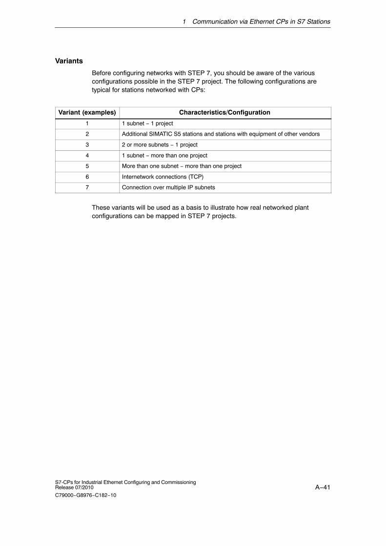
Variants
Before configuring networks with STEP 7, you should be aware of the variousconfigurations possible in the STEP 7 project. The following configurations aretypical for stations networked with CPs:
Variant (examples) Characteristics/Configuration
1 1 subnet − 1 project
2 Additional SIMATIC S5 stations and stations with equipment of other vendors
3 2 or more subnets − 1 project
4 1 subnet − more than one project
5 More than one subnet − more than one project
6 Internetwork connections (TCP)
7 Connection over multiple IP subnets
These variants will be used as a basis to illustrate how real networked plantconfigurations can be mapped in STEP 7 projects.

1 Communication via Ethernet CPs in S7 Stations
A−42S7-CPs for Industrial Ethernet Configuring and Commissioning
Release 07/2010
C79000−G8976−C182−10
1.7.1 Network/project variant : One subnet, one project
Configuration of the system
In the simplest case, your system consists of SIMATIC S7 stations connected byone subnet, for example of the type Industrial Ethernet.
Ethernet (1)
System“Produc-tion”
View in a STEP 7 project
You create an Industrial Ethernet object in the STEP 7 project. Stations createdin the same project refer to this object as soon as they are configured asnetwork nodes.
S7-400/1S7-300/1
S7-300/2
1 Communication via Ethernet CPs in S7 Stations
A−43S7-CPs for Industrial Ethernet Configuring and CommissioningRelease 07/2010
C79000−G8976−C182−10
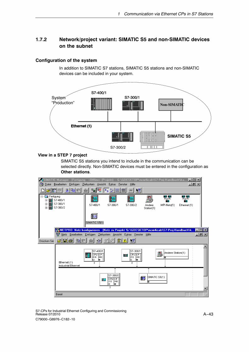
1.7.2 Network/project variant: SIMATIC S5 and non-SIMATIC deviceson the subnet
Configuration of the system
In addition to SIMATIC S7 stations, SIMATIC S5 stations and non-SIMATICdevices can be included in your system.
Ethernet (1)
System“Production”
SIMATIC S5
Non-SIMATIC
S7-400/1S7-300/1
S7-300/2
SIMATIC S5 stations you intend to include in the communication can beselected directly. Non-SIMATIC devices must be entered in the configuration asOther stations.
View in a STEP 7 project
Ethernet (1)
S7-400/1S7-300/1

1 Communication via Ethernet CPs in S7 Stations
A−44S7-CPs for Industrial Ethernet Configuring and Commissioning
Release 07/2010
C79000−G8976−C182−10
1.7.3 Network/project variant: Two or more subnets, one project
Configuration of the system
Due to the different tasks of the stations or due to the extent of the system it maybe necessary to operate more than one network.
View in a STEP 7 project
System“Production andManage-ment Level”
You can create the subnets in one STEP 7 project and configure the stations forcommunication.
S7-400/1
S7-300/1 S7-300/2
S7-400/2PROFIBUS CP
Ethernet CPEthernet (1)
PROFIBUS (1)
This representation illustrates the following:
� More than one subnet can be managed in one project.
� Each station is created once in the project.
� Each station can be assigned to more than one subnet by assigning its CPs todifferent subnets.

1 Communication via Ethernet CPs in S7 Stations
A−45S7-CPs for Industrial Ethernet Configuring and CommissioningRelease 07/2010
C79000−G8976−C182−10
1.7.4 Network/project variant: One subnet, multiple (sub) projects
Configuration of the system
In complex networked systems, during configuration it is sometimes more efficientto manage plant sections in different (sub) projects.
The situation can arise that communication takes place over an interproject subnetand that interproject connections must then also be created.
Example:
S7-400/1
S7 − 300/3
System section“Production 1”
S7-300/1 S7-300/2
S7-400/2
System section“Production 2”
Ethernet (1)
Organization in a multiproject
User-friendly and consistent configuration of such communication is supported inSTEP 7 as of Version V5.2 with the multiproject.
The functions for multiprojects in STEP 7 allow the following:
� Several projects can be managed in one multiproject and edited separately
� Projects can be branched and merged
Two different strategies can be distinguished in a multiproject:
� Several employees work at the same time on a multiproject in a networkedenvironment. The projects of the multiproject are in different network folders. Inthis case, all connection partners are available for configuring connections.
� One employee manages the multiproject centrally. This person creates thestructures for projects (when necessary locally) and contracts individual projectsout for external editing. The central configuration engineer then returns theseprojects to the multiproject and synchronizes the interproject data with systemsupport and where necessary the executes the required interproject functions.
In this case, there must be agreement, for example regarding the assignment ofconnection names so that connections with identical names can easily bemerged.

1 Communication via Ethernet CPs in S7 Stations
A−46S7-CPs for Industrial Ethernet Configuring and Commissioning
Release 07/2010
C79000−G8976−C182−10
The topic of multiprojects is dealt with in detail in the STEP 7 basic help.
Here, you will find information on the following topics:
� Requirements for interproject functions
� How to create multiprojects
� How to create a new project in a multiproject
� How to separate a project from a multiproject
� How to include projects in the multiproject
� How to synchronize projects in a multiproject
� How to move stations within a multiproject (when a station is dragged from oneproject of a multiproject to another, the interproject connections are retained.)
� Possible problems in distributed projects and tips on how to avoid them
Possibilities for stations outside the current project
The addition of the multiproject functionality means that the following situations canarise:
� Connection to a partner in an unknown project
The new multiproject functionality allows you to create a connection to a partnerin an unknown project. In this case, you can specify a connection name as areference in the properties dialog of the connection. When the projects aremerged, STEP 7 then supports you with automatic synchronization of theseparately configured connections.
The connection remains unspecified until the projects have been merged andthe connections synchronized. Only following this synchronization can theconfiguration data be downloaded to the local station without inconsistencies.
You should therefore use this variant when you know that the projects will bemerged in a multiproject.
� Specified connections with representative objects
To allow you to create specified connections to stations in a different project (forexample production 2) or that are not managed with STEP 7, you can configurethese stations as other stations(example in the project production 1).
This allows you to create consistent, fully specified configuration data and todownload it to the local station.
It is also possible to create specified connections between these stations indifferent, independent projects. The stations can then communicateimmediately over the created connections after the configuration data havebeen downloaded.
Use this variant when you want to operate projects separately due to thecomplexity.
Stations of the type SIMATIC S5 function in just the same way asrepresentative objects.

1 Communication via Ethernet CPs in S7 Stations
A−47S7-CPs for Industrial Ethernet Configuring and CommissioningRelease 07/2010
C79000−G8976−C182−10
Merging projects in the multiproject:
If you have used the multiproject functions allowing you to use connections to apartner in an unknown project, STEP 7 will automatically attempt to synchronizetwo separately configured connections.
If you have configured projects with representative objects and want to mergethese projects into a multiproject, you have the following options:
� You can leave the representative objects with the configured connectionsunchanged.
� You can reassign the connection partner and then delete the representativeobjects.

1 Communication via Ethernet CPs in S7 Stations
A−48S7-CPs for Industrial Ethernet Configuring and Commissioning
Release 07/2010
C79000−G8976−C182−10
1.7.5 Network/project variant: Multiple subnets in multiple (sub)projects
Configuration of the system
If several network types need to be used and if these need to be managed indifferent projects due to the different tasks of the stations or due to the large spanof the plant, stations can be created as follows:
� Using (sub) projects in the “multiproject”
� by configuring “Other stations / SIMATIC S5” in the other project.
S7 − 300/1 S7 − 300/2
S7 − 400/1
Cell level = (sub)project 1
Cell level = (sub)project 2
PROFIBUS CP
Ethernet (1)
PROFIBUS (1)
Ethernet CP

1 Communication via Ethernet CPs in S7 Stations
A−49S7-CPs for Industrial Ethernet Configuring and CommissioningRelease 07/2010
C79000−G8976−C182−10
Organization in a multiproject
If you use a multiproject organization, follow the steps below to connect theS7-400/1 station to the PROFIBUS (1) subnet:
Create a subnet of the type PROFIBUS in both subprojects and merge these twosubnets in NetPro.
Representative objects for stations outside the current project
If you do not want to use the multiproject functions, you can fall back on the use ofrepresentative objects as used previously.
To be able to network the representative objects, you must once again create asubnet of the type PROFIBUS in both projects as shown in the example here.

1 Communication via Ethernet CPs in S7 Stations
A−50S7-CPs for Industrial Ethernet Configuring and Commissioning
Release 07/2010
C79000−G8976−C182−10
1.7.6 Network/project variant: Connections across subnets (TCP/IP)
Configuration of the system
If connections are required to stations on network structures connected by routersdue to the differing tasks of the stations or the large span of the network, thestations in the other project can be reached by configuring “Other Stations”.
S7 − 400/1
Ethernet CP
S7 − 400/2
Ethernet CP
* only TCP/IP
Router *
S7 − 300/1
Ethernet (1)
Ethernet (2)
WANInternet *
If the stations in the two networks are managed in the same project, thenetworking appears as shown below in NetPro.
View in a STEP 7 project

1 Communication via Ethernet CPs in S7 Stations
A−51S7-CPs for Industrial Ethernet Configuring and CommissioningRelease 07/2010
C79000−G8976−C182−10
1.7.7 Network/project variant: IP connection across subnets (TCP/IP)
Configuration of the system
If for example, you want to access to the production network from your companynetwork (PG/PC), you can use an Advanced CP.
PG/PC
S7 − 400
Ethernet CP
S7 − 300
Ethernet (1)(157.0.0.0)
Ethernet (2)
Advanced CP
Gigabit interface(157.55.80.1)
PROFINET interface
The following two cases must be distinguished when configuring the PC.
� The PC is integrated in the STEP 7 project:
For the network attachment of your PG/PC, enter the use of a default router inthe STEP 7 project.
Under “Default router”, enter the IP address of the connected interface of theAdvanced CP as the address of the default gateway.
� The PC was not configured with STEP 7:
Enter the route manually in the input prompt. Depending on the operatingsystem, the command may, for example appear as follows.
− Windows PC:
route −p ADD 157.0.0.0 MASK 255.0.0.0 157.55.80.1
(The parameter “−p” ensures that the entry is saved in the registry and istherefore retained following a restart on the PC.)
As an alternative, you can also enter these Windows address parameters inthe properties dialog of the Ethernet interface:
Start menu > Settings > Control Panel > Network Connections > propertiesof the Interface > select network properties of the connection > entry in the“Internet Protocol Properties” dialog

1 Communication via Ethernet CPs in S7 Stations
A−52S7-CPs for Industrial Ethernet Configuring and Commissioning
Release 07/2010
C79000−G8976−C182−10
− UNIX PC:
route add −net 157.0.0.0 netmask 255.0.0.0 gw 157.55.80.1
Explanation of the example:157.0.0.0 = target network255.0.0.0 = netzmask157.55.80.1 = address of the default gateway)
When forwarding IP addresses, the Advanced CP does not distinguish betweenpublic and private addresses.

2 Characteristics of the Ethernet CPs
A−53S7-CPs for Industrial Ethernet Configuring and CommissioningRelease 07/2010
C79000−G8976−C182−10
2 Characteristics of the Ethernet CPs
2.1 Communications processors for S7-300
The module was designed to match the components of the S7-300/C7-300programmable logic controller and has the following features:
� Compact modules (single or double-width) for simple installation on the S7standard rail
� Can be used in central or expansion racks;
� The displays are all located on the front panel
� No fan necessary;
� Direct backplane bus connection via the supplied bus connector;
� Interfaces available depending on the device type
− 2 x RJ-45 jack as 2-port switch PROFINET for attachment to twisted-pairEthernet,
− 1 x RJ-45 jack for attachment to gigabit Ethernet
� Interfaces narrow design: 2 x RJ-45 jacks as 2-port switch PROFINET for attaching the CP to twisted-pairEthernet
� The project engineering of the CP is possible over MPI or LAN/IndustrialEthernet. The version of STEP 7 released for the device type is necessary.

2 Characteristics of the Ethernet CPs
A−54S7-CPs for Industrial Ethernet Configuring and Commissioning
Release 07/2010
C79000−G8976−C182−10
LEDs
Text with MAC addresses
Firmware version
Behind front panel:
PROFINET interface:2 x 8-pin RJ-45 jack
Gigabit interface:1 x 8-pin RJ-45 jack
Behind frontpanel:
X = Placeholder for hardwareversion
C-PLUG(at rear)
Figure 2-1 Example: Front view of the CP 343-1 Advanced
2.2 Communications processors for S7-400
The module was designed to match the components of the S7-400 / S7-400Hprogrammable logic controller and has the following features:
� Single-width module for simple installation in the S7-400 / S7-400H rack.
� Can be used in central or expansion racks.
� The operator controls and displays are all located on the front panel.
� No fan necessary
� Interfaces:
− 2 x RJ-45 jack for attachment of the CP to twisted-pair Ethernet
or
− 4 x RJ-45 jack as 4-port switch PROFINET for attachment of the CP totwisted-pair Ethernet,1 x RJ-45 jack for attachment to gigabit Ethernet
� The project engineering of the CP is possible over MPI or LAN/IndustrialEthernet. The version of STEP 7 released for the device type is necessary.

2 Characteristics of the Ethernet CPs
A−55S7-CPs for Industrial Ethernet Configuring and CommissioningRelease 07/2010
C79000−G8976−C182−10
LEDs
PROFINET interface:4 x 8-pin RJ-45 jack
C-PLUG
Port 1
Port 2
Port 3
Port 4
X = Placeholder forhardware version
Text with MAC addresses
Gigabit interface:1 x 8-pin RJ-45 jack
Firmware version
Figure 2-2 Example: Front view of the CP 443-1 Advanced

2 Characteristics of the Ethernet CPs
A−56S7-CPs for Industrial Ethernet Configuring and Commissioning
Release 07/2010
C79000−G8976−C182−10
2.3 Slot rules for SIMATIC S7-300
2.3.1 Permitted slots
In the SIMATIC S7-300 there is no set slot assignment for the SIMATIC NET CPs.Slots 4 to 11 are permissible (1, 2 and 3 cannot be used for CPs).
The SIMATIC NET CPs can be installed both in the central rack and in anexpansion rack, linked to the central rack via an IM 360/IM 361 (K-bus connection).
2.3.2 Number of SIMATIC NET CPs operated at the same time
The number of SIMATIC NET CPs that can be operated is not limited by thesystem (for example S7-300 CPU, slot rules etc.), but by the application (maximumcycle time of the application). The following components must be added into thecalculation of the cycle time on top of the existing S7 user program:
� Execution time of the FCs:
For communication between the S7-300 CPU and SIMATIC NET CPs, blocks(FCs/FBs) are necessary. How often these blocks are called depends on thenumber of connections or the number of SIMATIC NET CPs. Depending on theamount of data transmitted, every block call extends the time required by theuser program.
� Data conversion:
It may also be necessary for the information to be converted beforetransmission or after reception.
Please refer to the information in the relevant device manual.
2.3.3 Multicomputing
This functionality is not supported by the SIMATIC S7-300.

2 Characteristics of the Ethernet CPs
A−57S7-CPs for Industrial Ethernet Configuring and CommissioningRelease 07/2010
C79000−G8976−C182−10
2.3.4 Removing/inserting (module replacement)
Note
Removing and inserting the SIMATIC NET CPs for the SIMATIC S7-300 while thepower is on not permitted.
You should also remember that by removing a module from the rack, all moduleson the other side of it will be disconnected from the CPU.
A PG is required to download the configuration after replacing a module. No PG isnecessary to download the configuration in the following situations:
� When the CP supports the option of storing the configuration data on the CPU,a module can be replaced without a PG (see CP−specific description).
� When the CP has a C−PLUG, you simply insert the C−PLUG in the new module
2.3.5 Note on S7-300 CPU: Connection resources
Note that when using older S7-300 CPUs (≤ CPU 316), a maximum of four S7 typeconnections for CP communication are supported. Of these four connections, oneis reserved for a PG and another for an OP (HMI = Human Machine Interface).The newer CPUs (from 10/99 onwards) support 12 and the CPU 318-2DP supports32 S7 connections.
As a result, the older S7-300 CPUs have only two “free” S7 connections available.These two connections can be used for S7 communication, for PROFIBUS-FMS,for longer data, or FETCH, WRITE and TCP connections with Industrial Ethernet.
If you use CPs that support multiplexing of OP connections and S7 communicationusing loadable communication blocks, only 1 connection resource is occupied ifyou use both services.
Notice
Depending on the CP type installed and the services being used, there may beother restrictions (see CP-specific description in this manual).

2 Characteristics of the Ethernet CPs
A−58S7-CPs for Industrial Ethernet Configuring and Commissioning
Release 07/2010
C79000−G8976−C182−10
2.4 Slot rules for SIMATIC S7-400
2.4.1 Permitted slots
An S7-400 CP can be inserted both in the central rack and in the expansion rackwith a K bus interface.
In the SIMATIC S7-400, there is no set slot assignment for the SIMATIC NET CPs.Slots 2...18 are permitted. Remember, however, that slot 1 and, depending on thepower supply module used, also slots 2−3 (and 4 in redundant mode), areoccupied by the power supply modules.
2.4.2 Number of SIMATIC NET CPs operated at the same time
The number of SIMATIC NET CPs that can be operated simultaneously is limitedby the specific characteristics of the CPU. The exact number can be found in theCP-specific section of this manual.
There may be a further restriction resulting from the maximum currentconsumption depending on the power supply used. You should also note anyrequirements resulting from the interface types used (for example RJ-45 or AUI).
2.4.3 Multicomputing
The communication load can be distributed by installing several SIMATIC NETCPs (distribution of load). If, however, you want to increase the number ofavailable connection resources, you can insert several CPUs in a rack(multicomputing). All S7-400 CPUs in a rack can communicate via one or moreSIMATIC NET CPs.
The following communication services support multicomputing:
� ISO transport connections
� ISO-on-TCP connections
� S7 functions
� TCP connections
� UDP connections
� E-mail connections

2 Characteristics of the Ethernet CPs
A−59S7-CPs for Industrial Ethernet Configuring and CommissioningRelease 07/2010
C79000−G8976−C182−10
2.4.4 Removing/inserting (module replacement)
Removing and inserting the SIMATIC NET CPs for the S7-400 while the power ison is possible without damaging the modules.
If a CP is replaced with a new CP with the same order number, the configurationdata simply needs to be downloaded again if it is not stored on the CPU (see alsoCP-specific sections of this manual).
2.4.5 Note on S7-400 CPU: Connection resources
Note that in the S7-400 CPU as well, one S7 connection is reserved for a PG anda further one for an OP (HMI = Human Machine Interface).
� Attaching the PG over MPI:
To run ONLINE functions from a PG ( for example module diagnostics) on forexample an S7-400 CP via the MPI interface, two connection resources(addressing of the interface and the K bus) are required on the S7-400 CPU.These two connection resources should be taken into account in the number ofS7 connections.
Example: The CPU 412-1 has sixteen free resources for S7 functions available.If a PG is to be used for diagnostics on the S7-400 CP and is connected to theMPI interface, two connection resources are required on the S7-400 CPU, sothat 14 connection resources remain available.
� PG connection via PROFIBUS or Industrial Ethernet
If the PG is connected to the LAN (PROFIBUS or Industrial Ethernet), in orderto execute PG functions on the S7-400 CPU and diagnostics on an S7-400 CP,only one connection resource on the S7-400 CPU is necessary.

A−60S7-CPs for Industrial Ethernet Configuring and Commissioning
Release 07/2010
C79000−G8976−C182−10
3 Operating the Ethernet CP withSTEP 7/NCM S7
To attach a SIMATIC station via the Ethernet CP to Industrial*Ethernet, youconfigure the CP with the NCM S7 configuration software. This chapter explainsthe following:
� How the CP is configured in the STEP 7 project
� How the various network configurations are managed (setting up access toother systems)
� How to control and supply the CP with data using NCM S7
You will find further information in the following sources:
� When installing the Ethernet CP, please read the instructions in thedevice-specific Part B of this manual. This also contains further informationabout the performance of the Ethernet CP .
� For more information about the functions and applications of STEP 7 in whichthe NCM S7 option is integrated, please read the following topics:
− For using the help functions, read the section Working with STEP 7 in /6/.
− Configuring and assigning parameters to modules in /6/
− Configuring networks in /6/. You will find this information in the online helpwith integrated in STEP 7 You can open this with Help � Contents.
� You will find examples of configurations in the Primer.

3 Operating the Ethernet CP with STEP 7/NCM S7
A−61S7-CPs for Industrial Ethernet Configuring and CommissioningRelease 07/2010
C79000−G8976−C182−10
3.1 How to commission an Ethernet CP
The essential steps in commissioning an Ethernet CP are shown in the followingoverview:
Notice
The chart below shows the basic steps. Please read the device-specificinstructions in “Installation and Commissioning” in the description of your CP(Manual Part B).
Install the CP on the S7 standard rail(S7-300) or in the S7 rack (S7-400).
Connect the power supply.
Connect the CP to Industrial Ethernet.
Install the STEP 7 configurationsoftware on a PG/PC.
Configure the Ethernet CP:
� by configuring in theproject engineeringsee Section 3.3
or
� by programming
Turn on the S7 station.
Download the configuration data and the user programs tothe S7 station and/or CP.
Use the diagnostic functions during commissioningand to analyze problems.
Configuring / ProgrammingInstallation and Commissioning
S7 - 300 / 400

3 Operating the Ethernet CP with STEP 7/NCM S7
A−62S7-CPs for Industrial Ethernet Configuring and Commissioning
Release 07/2010
C79000−G8976−C182−10
3.2 General information on STEP 7 / NCM S7
Installation
The functions of NCM S7 are available automatically immediately after installingSTEP 7.
Functions
NCM S7 consists of the following:
� CP-specific index dialogs that you call using the properties dialog box of themodules.
� Dialogs for the connection configuration
� Diagnostic functions that you obtain as follows:
− Using the “Diagnostics” tab in the properties dialog
− Using the standard Start menu of Windows with which you can call theSIMATIC program group
� Functions available in the Start menu of Windows under SIMATIC � STEP 7 �NCM S7...:
− Diagnostics
− Firmware loader
Access to online help of STEP 7 and NCM S7
With the online help, you can obtain the following information:
� You can display the contents of the STEP 7 basic help system with the menucommand Help −> Contents.
� Context-sensitive help on the selected object using the Help −>Context-Sensitive Help menu command, the F1 key or the question mark intoolbar.
You can then access further information relating to the current topic.
� Glossary for all STEP 7 applications by clicking the “Glossary” button
F1

3 Operating the Ethernet CP with STEP 7/NCM S7
A−63S7-CPs for Industrial Ethernet Configuring and CommissioningRelease 07/2010
C79000−G8976−C182−10
3.3 Configuring − how it is done?
A CP is managed in an S7*project just as the other modules. You use STEP 7 toconfigure the hardware and create and manage the user software (see /6/).
Configuring a CP involves the following steps (the broken lines indicate options):
Programming theSEND/RECEIVE interface(see Chapter 4)
Create the Industrial Ethernet subnet (see 3.3.1)
Enter the Ethernet CP in the hardware configuration (see 3.3.2)
Make further CP settings (see 3.4)
Configuring communication connections (Chap. 5)− S7 connections /6/− ISO transport connections − ISO-on-TCP connections− TCP connections− UDP
Download the configuration to the PLC (see 3.10).
Configuration data inthe STEP 7 project
Check or set the network properties
Attach the Ethernet CP to the Ethernet subnet (see 3.3.2)
Display the network attachments of a station (see 3.3.3)
alternative:Program communicationconnections
User programs in the STEP7 project

3 Operating the Ethernet CP with STEP 7/NCM S7
A−64S7-CPs for Industrial Ethernet Configuring and Commissioning
Release 07/2010
C79000−G8976−C182−10
3.3.1 Creating an Industrial Ethernet subnet
Aims
To be able to attach the SIMATIC stations to a subnet, you create the subnet inyour project. This means that all the parameters for the entire subnet are managedcentrally.
Procedure
It is advisable to create the subnet before you configure the stations since theassignment of the SIMATIC stations is then performed largely automatically.
It is also possible to create the subnet at a later point in time when configuring aCP. This is explained in more detail later in the chapter.
Follow the steps outlined below:
1. Select the project in the SIMATIC Manager.
2. Select Insert � Subnet � Industrial Ethernet.
Result: An object of the type network is created in the project. This allows allthe SIMATIC stations created in the project to be attached to this subnet.
Figure 3-1 Project with assigned Ethernet network
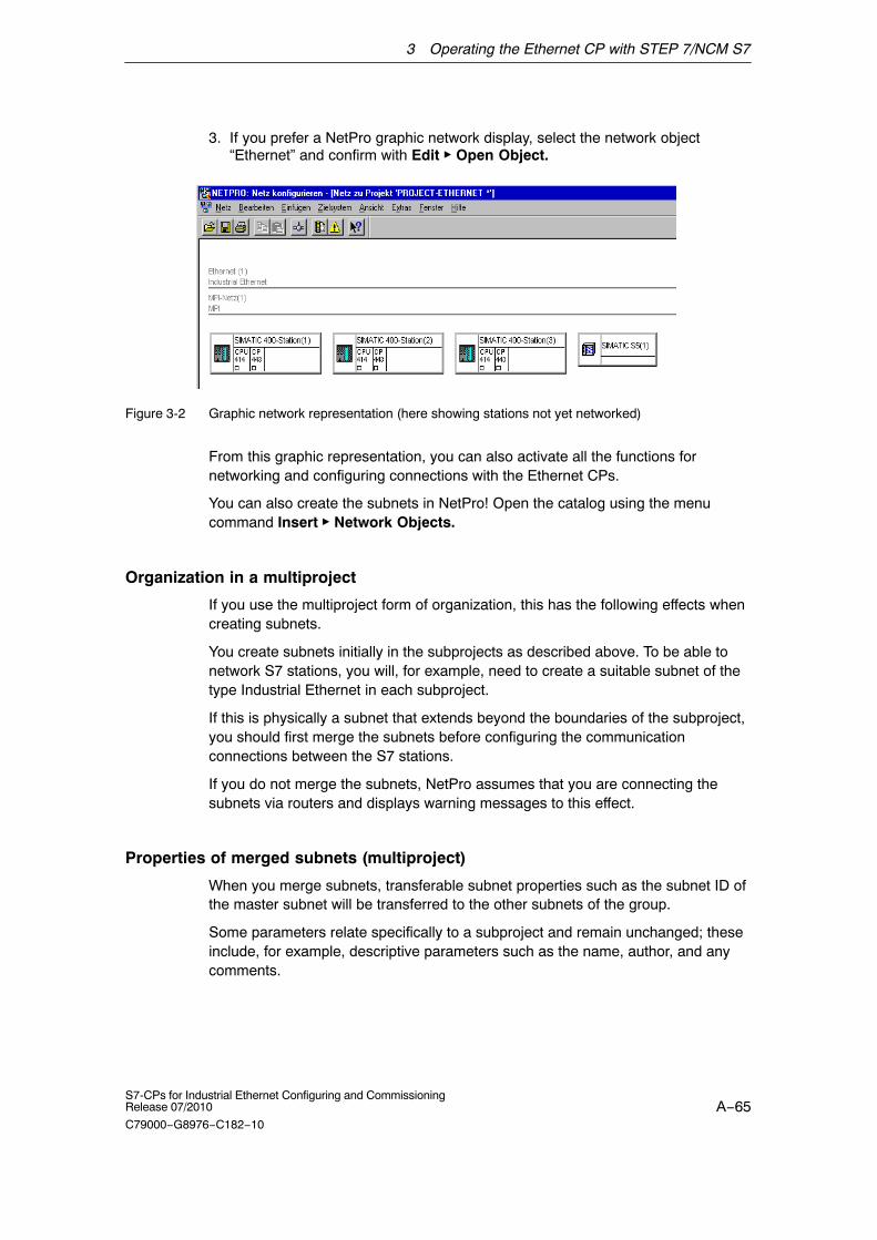
3 Operating the Ethernet CP with STEP 7/NCM S7
A−65S7-CPs for Industrial Ethernet Configuring and CommissioningRelease 07/2010
C79000−G8976−C182−10
3. If you prefer a NetPro graphic network display, select the network object“Ethernet” and confirm with Edit � Open Object.
Figure 3-2 Graphic network representation (here showing stations not yet networked)
From this graphic representation, you can also activate all the functions fornetworking and configuring connections with the Ethernet CPs.
You can also create the subnets in NetPro! Open the catalog using the menucommand Insert � Network Objects.
Organization in a multiproject
If you use the multiproject form of organization, this has the following effects whencreating subnets.
You create subnets initially in the subprojects as described above. To be able tonetwork S7 stations, you will, for example, need to create a suitable subnet of thetype Industrial Ethernet in each subproject.
If this is physically a subnet that extends beyond the boundaries of the subproject,you should first merge the subnets before configuring the communicationconnections between the S7 stations.
If you do not merge the subnets, NetPro assumes that you are connecting thesubnets via routers and displays warning messages to this effect.
Properties of merged subnets (multiproject)
When you merge subnets, transferable subnet properties such as the subnet ID ofthe master subnet will be transferred to the other subnets of the group.
Some parameters relate specifically to a subproject and remain unchanged; theseinclude, for example, descriptive parameters such as the name, author, and anycomments.

3 Operating the Ethernet CP with STEP 7/NCM S7
A−66S7-CPs for Industrial Ethernet Configuring and Commissioning
Release 07/2010
C79000−G8976−C182−10
Notice
Preserving consistency in merged subnets
After merging the subnets, you should check the consistency throughout themultiproject using the menu command Network > Check Interproject Consistencyin NetPro to make sure that there is consistency throughout the multiproject. Thischeck, for example, identifies S7 subnet IDs that are not unique in the multiproject.
3.3.2 Entering an Ethernet CP in the hardware configuration
Procedure
By installing and assigning the Ethernet CP in the rack of a SIMATIC station, youestablish the logical attachment between the Internet CP and the subnet.
1. Select the station in your project that you want to attach to Industrial Ethernetusing an Ethernet CP.
2. Select the CP in the hardware configuration just like any other module byselecting it in the hardware catalog and then selecting the slot in the rack.
You select CPs in the hardware catalog using a short text and the ordernumber.
Result: The CP is assigned to the SIMATIC station.
For information about the permitted slots, refer to /1/.
How to configure a module with STEP 7 is described in detail in /6/.
Subnet attachment
To allow you to activate the network attachment of the Ethernet CP, the SIMATICManager displays the following dialog:
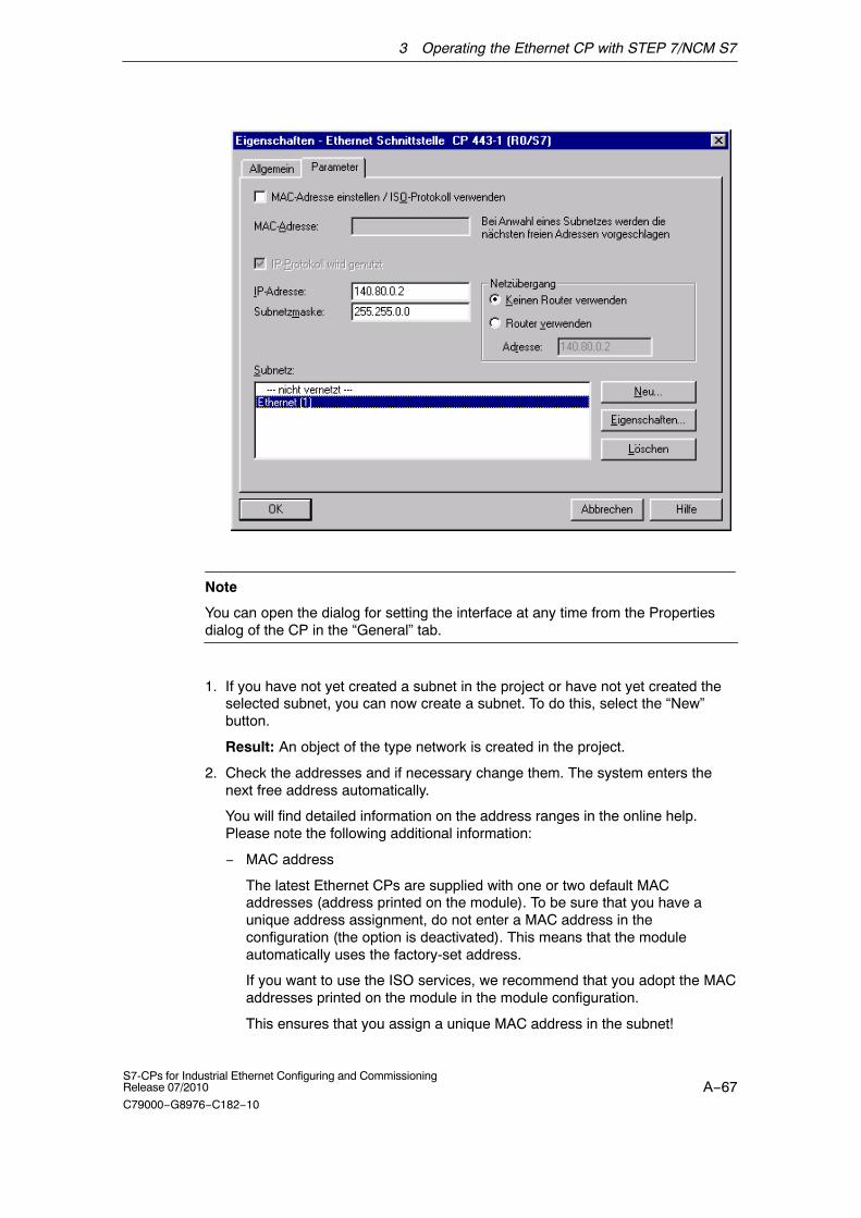
3 Operating the Ethernet CP with STEP 7/NCM S7
A−67S7-CPs for Industrial Ethernet Configuring and CommissioningRelease 07/2010
C79000−G8976−C182−10
Note
You can open the dialog for setting the interface at any time from the Propertiesdialog of the CP in the “General” tab.
1. If you have not yet created a subnet in the project or have not yet created theselected subnet, you can now create a subnet. To do this, select the “New”button.
Result: An object of the type network is created in the project.
2. Check the addresses and if necessary change them. The system enters thenext free address automatically.
You will find detailed information on the address ranges in the online help.Please note the following additional information:
− MAC address
The latest Ethernet CPs are supplied with one or two default MACaddresses (address printed on the module). To be sure that you have aunique address assignment, do not enter a MAC address in theconfiguration (the option is deactivated). This means that the moduleautomatically uses the factory-set address.
If you want to use the ISO services, we recommend that you adopt the MACaddresses printed on the module in the module configuration.
This ensures that you assign a unique MAC address in the subnet!

3 Operating the Ethernet CP with STEP 7/NCM S7
A−68S7-CPs for Industrial Ethernet Configuring and Commissioning
Release 07/2010
C79000−G8976−C182−10
If you replace a module, the MAC address of the predecessor is adoptedwhen you load the configuration data; configured ISO transport connectionsremain operable.
Note
If you exchange CP modules in your plant often, you can avoid double assignmentof MAC addresses when using ISO services, for example, by following theprocedure below:
Enter the first 3 vendor−specific bytes of the printed MAC address in theconfiguration.
For the last 3 bytes, enter application−specific IDs for your CP (in the example “ik”,“nm”, “yx” with a range of values of 0...255 decimal in each case).
Example: 00:0E:8C:ik:nm:xy
− IP address
With CPs with an additional gigabit interface, the IP address of thePROFINET interface must not be in the same IP subnet as the IP addressof the gigabit interface.
Note
The “IP address” and “Subnet mask” input fields have no significance for ISOtransport (option “IP protocol being used”).
3. Select the required subnet type in the “Subnet” list box.
4. You can display the properties dialog box for the selected subnet by clicking theProperties button.
5. Enter information specific to the subnet node in the “General” tab.
6. You must finally confirm your input with OK, otherwise the networking is notentered (refer to Point 3.).
Result: The CP is now configured as a network node for the corresponding S7station.
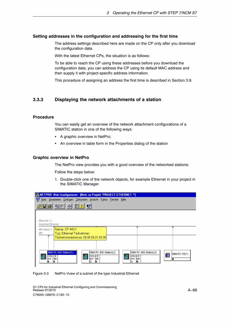
3 Operating the Ethernet CP with STEP 7/NCM S7
A−69S7-CPs for Industrial Ethernet Configuring and CommissioningRelease 07/2010
C79000−G8976−C182−10
Setting addresses in the configuration and addressing for the first time
The address settings described here are made on the CP only after you downloadthe configuration data.
With the latest Ethernet CPs, the situation is as follows:
To be able to reach the CP using these addresses before you download theconfiguration data, you can address the CP using its default MAC address andthen supply it with project-specific address information.
This procedure of assigning an address the first time is described in Section 3.9.
3.3.3 Displaying the network attachments of a station
Procedure
You can easily get an overview of the network attachment configurations of aSIMATIC station in one of the following ways:
� A graphic overview in NetPro;
� An overview in table form in the Properties dialog of the station
Graphic overview in NetPro
The NetPro view provides you with a good overview of the networked stations:
Follow the steps below:
1. Double-click one of the network objects, for example Ethernet in your project inthe SIMATIC Manager.
Figure 3-3 NetPro Vvew of a subnet of the type Industrial Ethernet

3 Operating the Ethernet CP with STEP 7/NCM S7
A−70S7-CPs for Industrial Ethernet Configuring and Commissioning
Release 07/2010
C79000−G8976−C182−10
Overview in table form
The table view in the Properties dialog of the station provides a detailed overviewof the components used for network attachment.
Follow the steps below:
1. Using the SIMATIC Manager, select the station in your project that you want tocheck.
2. Select the object properties using the menu command Edit � ObjectProperties or by double-clicking on the station symbol.
3. Select the “Interfaces” tab.
Result:
Figure 3-4 “Interface” tab in the “SIMATIC 300/400” properties dialog box
In the displayed dialog, you can see the subnet attachments that were configuredfor the SIMATIC station.

3 Operating the Ethernet CP with STEP 7/NCM S7
A−71S7-CPs for Industrial Ethernet Configuring and CommissioningRelease 07/2010
C79000−G8976−C182−10
3.4 Setting further CP properties
Overview
In addition to the network attachment, you can also make further settings for thespecific module or you can call functions.
1. Select the Ethernet CP in the hardware configuration.
2. Select “Edit” � “Object Properties”.
Depending on the type of CP you are using, the dialog displays other tabs inaddition to the “General” tab described in Section 3.3.2:
Table 3-1 Tabs and functions in the properties dialog of the CP
Tabs Settings for
General � Interface *)
� Module name
� Plant designation, location identifier
Addresses � Interface parameters for the user program
Options � Time-of-day synchronization
� SEND/RECEIVE (data length > 240 bytes)
� Module access protection (protection level)
� Replacing a module without a programming device
� Ethernet profile for fault-tolerant connections
� Individual network settings *)
� Send keepalives for connections
� Multiplex OP connections / reserve internal CPU connectionresources
� UDP buffering
� File system (remember this is case−sensitive) **)
Time-of-day synchronization � SIMATIC mode
� NTP mode (NTP: Network Time Protocol)
User **) � Specify user permissions for IT functions
Symbols **) � Symbolic access to variables using IT functions
DNS parameters **) � Specify the address of the DNS server for E−mail services (up to32 addresses)
Diagnostics � Call NCM diagnostics (special diagnostics / module diagnostics)
IP access protection � Edit IP access control list)
� Activate/deactivate Web server
� Activate / deactivate FTP server
IP Configuration � Configure the setting of the IP address
� Configure the way in which the IP address is configured
Port Parameters � Make the network settings *)

3 Operating the Ethernet CP with STEP 7/NCM S7
A−72S7-CPs for Industrial Ethernet Configuring and Commissioning
Release 07/2010
C79000−G8976−C182−10
Table 3-1 Tabs and functions in the properties dialog of the CP, continued
Tabs Settings for
FTP **) � Create / modify file allocation table
PROFINET � Specify properties for PROFINET IO and PROFINET CBA *)
Media redundancy � Configure the device as a node in a ring topology with themedium redundancy mode MRP *)
*) For CPs with configurable ports, there are some parameters in the properties dialogs of thePROFINET interface (PN−IO) or of the port submodules.
**) Only for Advanced CPs (CP 343−1 Advanced/IT, CP 443−1 Advanced/IT), see Section 3.4.9.
Please read the description of the Properties dialog of the CP in the integratedhelp. The functions are explained in detail there.
3.4.1 Addresses tab
The Addresses tab displays the address at which the module can be addressed bythe user program. You require this address when you call all SIMATIC NET blocks.These are, for example:
� FC blocks for transport connections
� FC10/11 for PROFINET IO
� FB40 for an FTP client
� FB55 (IP_CONFIG) for programmed connections
You will find the description of the SIMATIC NET blocks in /10/.
Notice
Please note the following notes on S7-300 stations:
If you selected the “Update OB1 process image cyclically” option in the CPUconfiguration (default), you must set the module base address of the Ethernet CPoutside the process image (base addresses in the “Addresses” tab).
Example: If the size of the process image selected for the CPU is 1024 (0...1023),the address for the Ethernet CP must be set equal to or higher than 1024.
F1

3 Operating the Ethernet CP with STEP 7/NCM S7
A−73S7-CPs for Industrial Ethernet Configuring and CommissioningRelease 07/2010
C79000−G8976−C182−10
3.4.2 Options tab
Depending on the CP type, you can make the following settings:
Table 3-2 Settings in the “Options” tab
Option Meaning / Effect
� Time-of-day synchronization In this tab, you can make the settings for one of the twosynchronizatoion modes:
� SIMATIC mode
If the CP receives MMS time messages, its local time of day issynchronized as long as the NTP mode was not configured (MMS= Manufacturing Message Specification).
The advantage of this mode is that it is generally more accuratethan the NTP mode.
� NTP mode (NTP: Network Time Protocol)
In the NTP mode, the CP sends time queries at regular intervals(in client mode) to NTP servers in the subnet (LAN). Based on theresponses of the servers, the most reliable and most accuratetime of day is identified and the time of day of the station issynchronized.
The advantage of this mode is that time−of−day synchronizationis possible beyond subnet boundaries.
Note
The time-of-day synchronization function does not exist for all moduletypes.
� SEND/RECEIVE (data length > 240 bytes)
With this option, you specify whether or not the CP will support jobswith a data length of more than 240 bytes (for S7-300 stations).
Notes
� The transfer of more than 240 bytes of data is supported asdefault by newer version CPs. With older CPs, the “data length> 240 bytes” function is supported by enabling this option. Pleasenote the information in the product information bulletin / manual ofthe Ethernet CP.
Note the information on the SEND/RECEIVE blocks in themanuals /10/ and /11/.
� With older CPs that provide this option, remember that thisconfiguration uses a connection resource (free connection for S7functions) of the S7−300 CPU! CPU connection resources arealso used, for example, by S7-300 CPs, in the FMS mode or byPGs and OPs. For more detailed information about the maximumconnection resources.

3 Operating the Ethernet CP with STEP 7/NCM S7
A−74S7-CPs for Industrial Ethernet Configuring and Commissioning
Release 07/2010
C79000−G8976−C182−10
Table 3-2 Settings in the “Options” tab , continued
Option Meaning / Effect
� Module access protection(protection level)
With this function, you can protect the CP from accidentalintervention during productive operation. The following options areavailable:
� Not locked
� Status−dependent
With this setting, it is only possible to write to the CP when theCPU is in STOP mode.
This is the recommended setting.
The default is “Not locked”.
� Replacing a module without aprogramming device
With this option, you can have the configuration data of the CP storedon the CPU. If you then replace CP, the configuration data for thenew CP are downloaded automatically from the CPU when the CP isstarted up.
If you select this option, the configuration data are stored long-termon the CPU instead of in the EPROM of the CP. Remember, however,that long-term storage on the CPU is only safe from power outages ifthe CPU is protected by battery backup or by using an S7 MemoryCard.
Note
If you store the configuration data on the CPU, please read the notebelow.
The following functions do not modify the configuration data on theCPU:
� Reset module memory
� Resetting to factory settings
� Assigning an IP address1) (using the target system selection inthe SIMATIC Manager or the properties dialog in HW Config orNetPro)
If you subsequently upload the configuration data from the CPU to aPG you will always object the configuration data that were previouslyon the CP (with parameters, connections, IP address).
1) Note: You should only use the assign IP address function duringcommissioning; in other words, before downloading the configurationdata.
� Ethernet profile forfault-tolerant connections
Select this profile if you use fault-tolerant communication in yoursystem. Fault-tolerant communication means that Industrial Ethernetis designed with redundancy and that you have configuredfault-tolerant S7 connections.
If you select the Ethernet profile for fault-tolerant connections here,the time response of the S7 connections is adapted. As a result,breakdowns of a connection are detected more quickly and thefailover to redundant connections is faster.
Note
Select the Ethernet profile for fault-tolerant connections only whenyou actually use fault-tolerant S7 connections. Otherwise you mustexpect your system to be more susceptible to problems since, forexample, the number of transfer or connection establishmentattempts is reduced compared with non-redundant systems.

3 Operating the Ethernet CP with STEP 7/NCM S7
A−75S7-CPs for Industrial Ethernet Configuring and CommissioningRelease 07/2010
C79000−G8976−C182−10
Table 3-2 Settings in the “Options” tab , continued
Option Meaning / Effect
� Individual network settings Here, you can make fixed network settings, when necessary. Asdefault, “Automatic Setting” is selected and this setting generallyguarantees problem-free communication in most situations.Whenever possible, leave the “Automatic settings” unchanged.
If isolated problems occur in communication (for example, whenconnections are not established or when there are often disruptionson the network), the reason may be that the selected or automaticnetwork settings are not suitable. You can then select a networksetting to suit your network configuration.
� Send keepalives forconnections
Here, you can set the interval at which keepalives are sent to thepartner of a communications connection. This setting decides thelatest time after which the failure of a communications partner isdetected.
For all connection-oriented services, the Ethernet CP is configured sothat keepalives are sent. This guarantees that connections areclosed if a communications partner fails and that the connectionresources are released. The setting made here applies to all TCPand ISO-on-TCP connections operated via the CP; aconnection-oriented setting is not possible.
Possible values:
Default setting: 30 seconds
Disable keepalive: 0 seconds
Maximum value: 65535 seconds
Notes / Recommendations:
Remember that the keepalive mechanism can keep underlyingconnections established (for example, an ISDN telephoneconnection) although no user data are actually being transmitted. Ifthis is not required, set the interval so high that the underlyingconnection is closed down when no further user data are sent beforea keepalive is sent.

3 Operating the Ethernet CP with STEP 7/NCM S7
A−76S7-CPs for Industrial Ethernet Configuring and Commissioning
Release 07/2010
C79000−G8976−C182−10
Table 3-2 Settings in the “Options” tab , continued
Option Meaning / Effect
� Multiplex OP connections /reserve internal CPUconnection resources
To attach TD/OPs or HMI devices, you can optimize the connectionresources on the S7-300 CPU by having up to 16 of these devicescommunication on a single CPU connection resource (multiplexmode).
If you do not use this option, the number of operable TD/OPs or HMIdevices depends on the number of available connection resources ofthe CPU you are using.
As default, this option is deactivated. This means that a CPUconnection resource is used for multiplex only when necessary.
Configured S7 connections over the CP use the same multiplexchannel as you use for multiplexing the HMI connections. If youconfigure S7 connections, this means that one CPU connectionresource is already used.
Please note: PG connections do not use the multiplexer; if you use aPG, one connection resource is always occupied.
Note on programming:When you use the multiplex mode, you must specify the rack/slotassignment of the CP for addressing on TD/OP/HMI connectionsinstead of the rack/slot assignment of the CPU!
Applications (for example ProAgent) that require block-relatedmessages (Alarm_S: SFC17-19) are not supported in the multiplexmode.
� Disable UDP frame buffering With this option, you select the following response:
� Disabled (default)
All the UDP frames received from the CP are buffered until theyhave been transferred to the CPU or the internal buffer hasoverflowed.
Following a buffer overflow, newly arriving frames are discarded.
Disabling the response associated with the option can be criticalin certain applications when there is a lot of frame traffic. Bybuffering a lot of frames, there may be an unwanted time offsetbetween the frames detected on the CPU and the frame currentlybeing received on the Ethernet interface.
� Enabled
The CP always transfers only the last received, in other words,the current frame to the CPU. As long as no new UDP frame canbe transferred between the CP and CPU due to the currentcommunication load, only the last frame to arrive is buffered onthe CP (memory size = 1).
Enabling the function achieves the shortest possible reaction timebetween a UDP frame arriving and its evaluation on the CPU.
3.4.3 Time-of-day Synchronization tab
In this tab, you can make the settings for one of the two synchronization modesexplained below:

3 Operating the Ethernet CP with STEP 7/NCM S7
A−77S7-CPs for Industrial Ethernet Configuring and CommissioningRelease 07/2010
C79000−G8976−C182−10
� SIMATIC mode
If the CP receives MMS time-of-day frames, its local time is synchronizedproviding the NTP mode was not configured (MMS = Manufacturing MessageSpecification).
The advantage of this mode is the accuracy that is generally higher thanachieved with the NTP mode.
With the ”Forward time” option, this time can be forwarded to the station.
� NTP mode (NTP: Network Time Protocol)
In the NTP mode, the CP sends time queries (in the client mode) at regularintervals to the NTP server in the subnet (LAN). Based on the responses of theserver, the most reliable and most accurate time is calculated and the time issynchronized on the station.
The advantage of this mode is that the time of day can be synchronized beyondthe boundaries of the subnet.
Some CPUs themselves provide the option of obtaining the time of day from anNTP server. If you enable this option on the CPU, you should disable theforwarding of the time to the station in the CP. This avoids the time of dayobtained directly from the NTP server being overwritten by the time acquired bythe CP. Forwarding via the CP may result in less accuracy.
Note
Remember that if you have the time of day forwarded to the CPU, you will need tomake the synchronization setting “As slave” for the CPU.
3.4.4 Diagnostics tab
In the “Diagnostics” tab, you can start NCM S7 Diagnostics (see Chapter 11).
3.4.5 IP Access Protection tab
Function
Using IP access protection gives you the opportunity of restricting communicationover the CP of the local S7 station to partners with specific IP addresses. Partnersyou have not authorized cannot access data of the S7 station over the CP usingthe IP protocol (S7 connections).
IP access protection relates to all messages handled using the IP protocol (TCP,ISO-on-TCP, UDP, ICMP).

3 Operating the Ethernet CP with STEP 7/NCM S7
A−78S7-CPs for Industrial Ethernet Configuring and Commissioning
Release 07/2010
C79000−G8976−C182−10
In this tab, you can activate or deactivate IP access protection and can enter IPaddresses in an IP access control list (IP-ACL).
With Advanced CPs, it is possible to send entries for the IP access control list tothe CP using HTTP (see Section 3.5).
Registering blocked access attempts
Attempts at access that are blocked are registered on the CP. You can view theseentries with NCM Diagnostics in the “IP access protection” diagnostic object. If theCPs provides Web diagnostics, the information is also available there.
With Advanced CPs up to the CP 343-1 Advanced (GX21) andCP 443-1 Advanced (EX41), blocked access attempts are stored in the CP’s ownfile system in a LOG file that you can view with a Web browser. You will find theLOG file as an HTML file in the file system of the CP in the following directory:
− ram/security/IPLogFile.htm
With Advanced CPs as of CP 343−1 Advanced (GX30) and CP 443−1 Advanced(GX20), the LOG file is not created. On these CPs, you can view the blockedaccess attempts directly with Web diagnostics.
Response to enabled IP access protection
� Configured connections with specified partners
If you want to restrict access to the precise set of partners you specify duringconnection configuration, you simply need to activate access protection. In thiscase, you do not need to enter IP addresses in the list. The IP addresses youhave specified in the connection configuration, are entered automatically in theIP−ACL. This also applies to IP addresses obtained dynamically over an E-mailconnection from a DNS server.
All other partners are ignored.
If the CP has multiple interfaces, this allows access to the station. Other accessrights (IP routing) must be configured extra.
� Configured connections with unspecified partners
All partners on unspecified connections (without a non−configured IP address)are rejected. This also applies to connection partners specified in the userprogram with the function block FB55.
If you want to authorize other partners when IP access protection is enabled, enterthem in the IP−ACL. This applies, in particular, to nodes from connections withpassive connection establishment.

3 Operating the Ethernet CP with STEP 7/NCM S7
A−79S7-CPs for Industrial Ethernet Configuring and CommissioningRelease 07/2010
C79000−G8976−C182−10
Configuration
� “Activate Web server” option
The CP provides you with the function of a Web server for access using a Webbrowser. To allow this, certain HTML pages with CP information and diagnosticsfunctions are stored in a memory area of the CP.
As default, Web server access is enabled.
Disable this option to block access to these HTML pages. This closes port 80 ofthe CP.
� “Activate FTP server” option
If the option is selected, FTP access to the S7 station is allowed. If youconfigure FTP access to file DBs on the CPU in the “FTP” tab, access to the S7station is possible.
As default, FTP server access is enabled.
If the option is disabled, FTP access is blocked by closing port 21 of the CP.
� Activate access protection for IP communication
As default, general IP access protection is disabled.
The configuration of IP access protection depends on whether the CP has 1 or2 interfaces. On CPs with 2 interfaces, you can also authorize the partners forIP routing via the CP.
Notice
If IP access protection is selected, you should also enter the IP address of yourconfiguration computer if you want to download a modified configuration to the CPlater or want to access the CP for diagnostic purposes.
Otherwise, you would have no access to the module with the configurationcomputer via the Ethernet interface of the CP!
With Advanced CPs, access authorizations can also be entered in the IPaccess control list. These have the following significance for the enteredcommunications partners:
Table 3-3
Access attribute Meaning
A (access) Access to the station is authorized.
M (modify) Modifying the IP access control list by HTTP is permitted.
R (routing) There is access to the subnet connected to the otherinterface of the CP.
For more detailed information, refer to the STEP 7 online help.
3 Operating the Ethernet CP with STEP 7/NCM S7
A−80S7-CPs for Industrial Ethernet Configuring and Commissioning
Release 07/2010
C79000−G8976−C182−10
Notice
You can view the IP-ACl with NCM Diagnostics.
When IP access protection is activated, remember that in the following specialcase, the IP−ACL is displayed as being empty and IP access protection as beingdeactivated:
� There is no connection configured and
� no fixed IP address entered in the IP−ACL and
� and no dynamic IP address is currently being obtained.
As soon as an IP address is entered, for example dynamically, IP accessprotection is displayed as activated again..
3.4.6 IP Configuration tab
In this tab, you can decide the route and the method with which the IP address ofthe local S7 station is obtained and assigned. With the options available here, it isalso possible to assign IP addresses dynamically outside the STEP 7configuration.
The following options do not apply to the gigabit interface of the Advanced CPs.The gigabit interface requires a fixed IP configuration.
Table 3-4 Options in the “IP Configuration” tab
Option Meaning / Effect
� Set IP address in the“Properties − EthernetInterface” dialog
This option is the default.
It means that the IP address is set during the networking of theEthernet CP. The IP address of the CP is therefore fixed in theconfiguration.
You must select this option if you want to configure specifiedconnections.

3 Operating the Ethernet CP with STEP 7/NCM S7
A−81S7-CPs for Industrial Ethernet Configuring and CommissioningRelease 07/2010
C79000−G8976−C182−10
Table 3-4 Options in the “IP Configuration” tab, continued
Option Meaning / Effect
� Obtain an IP address from aDHCP server
If you select this option, the IP address is obtained from a DHCPserver when the S7 station starts up.
The DHCP server is informed of the MAC address of the CP or theclient ID that you can enter here.
Requirement / Restriction:
If you select this option, it is initially not possible to create a fullyspecified connection in the STEP 7 project because the local IPaddress is not known.
You must therefore select “unspecified” with passive connectionestablishment as the connection type.
Please note the following:
If the connections are configured over the interface in the userprogram, you must use the option “Set IP address in the userprogram” as described below. This also applied if the IP address isobtained from a DHCP server.
� Set IP address in the userprogram
With this option, you specify that the IP address is set over a userprogram interface (function block IP_CONFIG). This allows the IPaddress to be supplied dynamically during operation.
In this situation, communication connections are created only overthe user program interface; configuring connections using STEP 7 isnot possible (relates to connections over IP: TCP, ISO-on-TCP, UDP).
This setting does not preclude the IP address being obtained from aDHCP server. It is possible for the user program to instruct themodule to obtain an IP address in this way.
Further information, see /10/:
� Set IP address using adifferent method
With this option, you specify that the IP address is set by otherservices outside STEP 7.
In this situation, configuring connections using STEP 7 is not possible(relates to connections over IP: TCP, ISO-on-TCP, UDP ).
Note
You can query the IP address actually being used with NCM S7 Diagnostics.

3 Operating the Ethernet CP with STEP 7/NCM S7
A−82S7-CPs for Industrial Ethernet Configuring and Commissioning
Release 07/2010
C79000−G8976−C182−10
3.4.7 “Port Parameters” tab
Here, you can, when necessary, make fixed network settings for the transmissionproperties of every port. As default, “Automatic Setting” is selected and this settinggenerally guarantees problem-free communication in most situations. Wheneverpossible, leave the “Automatic settings” unchanged.
If isolated problems occur in communication (for example, when connections arenot established or when there are often disruptions on the network), the reasonmay be that the selected or automatic network settings are not suitable. You canthen select a network setting to suit your network configuration.
3.4.8 “PROFINET” tab
Here, you specify the properties of the Ethernet CP for PROFINET IO andPROFINET CBA.
Table 3-5 Options / input areas in the “PROFINET” tab
Option / Input Area Meaning / Effect
� Operating Mode *) Depending on the CP device type, you can select the availablemodes in which you can operate the S7 station on PROFINET.
� PROFINET IO Controller
With this option, you specify whether or not the Ethernet CP willoperate as PROFINET IO controller. This can also be specified byassigning a PROFINET IO system to the CP in HW Config usingthe context menu (right mouse button).
� PROFINET IO device
With this option, you specify whether or not the Ethernet CP willoperate as PROFINET IO device. In a later step, you assign theCP to the PROFINET IO system as a PROFINET IO device.
� Device Name **) Name of the device (according to DNS conventions). The devicename must be unique on the Ethernet subnet. If the CP is operatingas PROFINET IO controller, the device name is derived from theshort identifier.
STEP 7 gives you the option of adding the name of the IO system aspart of the device name automatically. To use this feature, select theoption “Use name in device/controller” in the properties of thePROFINET IO system.
� CBA communication To be able to use the S7 station with PROFINET CBA, specify the CPto be used for the componentization for PROFINET CBA or SIMATICiMap.
*) For CPs with configurable ports, set the “PROFINET IO controller” mode in the context menu of theinterface slot. You do this in the configuration table of HW Config by selecting the row “X2 (PN−IO)”and opening the context menu with the right mouse button.
**) For CPs with configurable ports, there are some parameters in the properties dialogs of thePROFINET interface.

3 Operating the Ethernet CP with STEP 7/NCM S7
A−83S7-CPs for Industrial Ethernet Configuring and CommissioningRelease 07/2010
C79000−G8976−C182−10
3.4.9 Configuring IT functions
The settings described in this section are supported only by Advanced CPs.
“IP Access Protection” tab
If you want to block IP communication with HTTP (port 80) or FTP (port 21) for anAdvanced CP, enable the “Activate Web server” option or disable the “ActivateFTP server” option (see “IP Access Protection” tab). As default, both functions areenabled.
Options tab
Depending on the Advanced CP type, the following settings can be made:
� File system (case−sensitive)
By enabling this option, you can specify that the CP distinguishes upper andlower case in the names of files for the file system.
“Symbols” tab
This tab contains the symbols or structure elements of a data block defined as asymbol that can be reached via this CP. Using this tab is described in detail in theprogramming tips /18/.
“DNS Parameters” tab
This table contains the address of the DNS (Domain Name System). The DNSassigns the Internet address to symbolic addresses. If you prefer to use a symbolicaddress when you configure your E−mail, the absolute address is obtained byquerying the DNS specified here.
“Users” tab
In this tab, you specify which users have which permissions when accessing theS7 station via a Web browser or using FTP.
In the alphabetical list, you will find the users that have already been entered underuser name for which passwords have been saved.
The “Everybody” entry is a default entry and is always present. This entry cannotbe deleted. It is also not possible to assign a password to this entry. As default, norights whatsoever are assigned to this entry. For service purposes, it isnevertheless possible to assign rights. These rights must therefore be canceledagain after service work has been done.
V 5.4.4

3 Operating the Ethernet CP with STEP 7/NCM S7
A−84S7-CPs for Industrial Ethernet Configuring and Commissioning
Release 07/2010
C79000−G8976−C182−10
Notice
Make sure that you cancel any access rights assigned to “everybody”. Otherwiseyou allow everybody to use services without any authorization.
With the “Add” or “Edit” buttons, you display the dialog box in which you canspecify or modify rights.
The dialog illustrated shows the possible settings.
Figure 3-5 Properties dialog of a CP: “Users” tab with dialog open for assigning rights
Here, you select the access rights for the entered user.
� If you select the “Add...” button in the “Users” tab, the following applies:
Entries are accepted only after assigning a password.
� If you select the “Edit...” button in the “Users” tab, the following applies:
You can modify the rights only after entering the password.
If you delete a list entry, you do not need to enter the password. There is, however,a system prompt asking you to confirm your intention.
Authorized access to the process data is described in Section 10.2.3.
“FTP” tab
In this dialog, you can create / modify a file allocation table.

3 Operating the Ethernet CP with STEP 7/NCM S7
A−85S7-CPs for Industrial Ethernet Configuring and CommissioningRelease 07/2010
C79000−G8976−C182−10
With the information in the file allocation table, it is possible to address data blocksin one or more CPUs (up to 4) in an S7 station.
� ”Use Ethernet CP as FTP server for S7 CPU data”
To transfer data with FTP, create data blocks in the CPU of your S7 station; dueto their special structure, these are known here as file DBs.
When it receives an FTP command, the Ethernet CP as FTP server obtains theinformation about how the data blocks used in the S7 station for file transfer aremapped to files from a file allocation table (file file_db.txt).
You can create the file allocation table as follows and transfer it to the CP:
− By entering it in the “FTP” folder described here;
The file allocation table is then downloaded to the CP automatically alongwith the project engineering data.
− By creating a file_db.txt file directly.
You must then download the file allocation table created in this way to theCP.
The file allocation table file_db.txt is stored in the file system of the Ethernet CPin the /config folder.

3 Operating the Ethernet CP with STEP 7/NCM S7
A−86S7-CPs for Industrial Ethernet Configuring and Commissioning
Release 07/2010
C79000−G8976−C182−10
3.5 Sending entries for the IP access control list to the CP(Advanced CP) by HTTP
Meaning
Communications partners entered in the IP access control list with the “Modify”access right, can send entries to the CP for the IP access control list using HTTP.
The transfer has the following effect in the IP access control list of the addressedCP:
� With the access rights transferred using HTTP, entries configured with STEP 7can be modified but not deleted.
� Each list transferred by HTTP, invalidates a list transferred previously withHTTP.
Notice
A list transferred by HTTP is deleted if the power supply fails on the CP (powerOFF).
Call with POST request
To transfer additional access control entries with HTTP, use the POST method.
A POST request has the following structure:
POST /ACL HTTP/1.0\r\nHost: 192.168.1.11\r\nContent−Type: application/x−www−form−urlencoded\r\nContent−Length: ....\r\n\r\n192.168.1.55 a r m\r\n
The last line contains the actual entry for the IP access control list according to thesyntax described below and the meaning of the access attributes.
� Syntax
Create the entries for transfer to the IP access control list according to thefollowing syntax:
<IP_address>[<access_attribute1>][<access_attribute2>][<access_attribute3>]
� Access attribute

3 Operating the Ethernet CP with STEP 7/NCM S7
A−87S7-CPs for Industrial Ethernet Configuring and CommissioningRelease 07/2010
C79000−G8976−C182−10
Table 3-6
Access attribute Meaning
A (access) Access to the station is authorized.
M (modify) Modifying the IP access control list by HTTP is permitted.
R (routing) There is access to the subnet connected to the otherinterface of the CP.
For more detailed information, refer to the STEP 7 online help.
Simplified transfer with software tools
Simpler notation and specification of list from a text file is possible, for example,with the cURL software tool that is available as open source.
To transfer the AccessList.txt file to the CP with IP address 172.16.1.180, forexample, you can use the following entry in the Windows command line:
curl −0 −−url 172.16.1.180/ACL −−data−urlencode @AccessList.txt
� Example of entries in file: AccessList.txt
192.168.1.44 a r m192.168.1.45 a192.168.1.46 a192.168.1.47 a192.168.1.48 a

3 Operating the Ethernet CP with STEP 7/NCM S7
A−88S7-CPs for Industrial Ethernet Configuring and Commissioning
Release 07/2010
C79000−G8976−C182−10
3.6 Media Redundancy tab
3.6.1 Media redundancy options
To increase the availability of an Industrial Ethernet network with optical orelectrical bus topologies, there are several options available:
� Mesh networks
� Parallel connection of transmission paths
� Closing a linear bus topology to form a ring topology
3.6.2 Media redundancy in ring topologies
Structure of a ring topology
Nodes in a ring topology can be external switches and/or the integrated switchedof communications modules.
To set up a ring topology with media redundancy, the two free ends of a linearnetwork topology must be brought together in one device. The closing of the linearbus topology to form a ring is achieved with two ports (ring ports) of a device in thering. This device is the redundancy manager. All other devices in the ring areredundancy clients.
Figure 3-6 Devices in a ring topology with media redundancy
The two ring ports of a device are the ports that establish the connection to its twoneighboring devices in a ring topology. The ring ports are selected and set duringthe configuration of the device. On the module, the ring ports are indicated by “R”after the port number.

3 Operating the Ethernet CP with STEP 7/NCM S7
A−89S7-CPs for Industrial Ethernet Configuring and CommissioningRelease 07/2010
C79000−G8976−C182−10
Note
Before physically closing the ring, download the configuration of your STEP 7project to the individual devices.
How media redundancy works in a ring topology
When using media redundancy, the data paths between the individual devices arereconfigured if the ring is interrupted at any point. After the topology has beenreconfigured, the devices are accessible again in the recreated topology.
If there is no interruption in the network, the 2 ring ports in the redundancymanager are disconnected from each other so that no data frames can circulate. Interms of data transmission, the ring topology appears to be a linear bus. Theredundancy manager monitors the ring topology. It does this by sending testframes both from ring port 1 and ring port 2. The test frames run round the ring inboth directions until they arrive at the other ring port of the redundancy manager.
An interruption in the ring can be caused by failure of the connection between twodevices or by failure of a device in the ring.
When the test frames of the redundancy manager no longer reach the other ringport due to an interruption in the ring, the redundancy manager connects its tworing ports. With this substitute path, a functioning connection is establishedbetween all remaining devices in the form of a linear bus network topology.
The time between the ring being interrupted and the re−establishment of afunctioning linear bus topology is known as the reconfiguration time.
As soon as the interruption is eliminated, the original transmission paths arere−established, the ring ports in the redundancy manager are disconnected fromeach other and the redundancy clients informed of the change. The redundancyclients then use the new paths to the other devices.
If the redundancy manager fails, the ring becomes a functioning linear bus.
Methods of media redundancy
The following media redundancy methods are supported by SIMATIC NETproducts:
� HSR (High Speed Redundancy)
Reconfiguration time: 0.3 seconds
� MRP (Media Redundancy Protocol)
Reconfiguration time: 0.2 seconds
The mechanisms of these methods are similar. With both methods, up to 50devices can participate in the ring. HSR and MRP cannot be used in the ring at thesame time.
If you want to introduce media redundancy in a ring topology into your STEP 7project, select MRP.

3 Operating the Ethernet CP with STEP 7/NCM S7
A−90S7-CPs for Industrial Ethernet Configuring and Commissioning
Release 07/2010
C79000−G8976−C182−10
3.6.3 MRP
The “MRP” method conforms to the Media Redundancy Protocol (MRP) specifiedin the standard IEC 61158 Type 10 “PROFINET”.
The reconfiguration time after an interruption of the ring is a maximum of 0.2seconds.
Initial Situation
The following requirements must be met for problem−free operation with the mediaredundancy protocol MRP:
� MRP is supported in ring topologies with up to 50 devices. Exceeding thisnumber of devices can lead to a loss of data traffic.
� The ring in which you want to use MRP may only consist of devices thatsupport this function. These include, for example, the following devices:
− Industrial Ethernet switches
SCALANCE X 200 as of firmware version V4.0
SCALANCE X 200 IRT as of firmware version V4.0
− Communications processors
CP 443−1 Advanced (6GK7 443−1GX20−0XE0) as of firmware version V2.0
CP 343−1 Advanced (6GK7 343−1GX30−0XE0) as of firmware version V1.0
CP 1616 (6GK1 161 6AA00) as of firmware version V2.2
CP 1604 (6GK1 160 4AA00) as of firmware version V2.2
− Non−Siemens devices that support this function.
Other Siemens devices will support MRP in future.
� All devices must be interconnected via their ring ports.
� “MRP” must be activated on all devices in the ring (see “MRP configuration inPROFINET IO”).
� The connection settings (transmission medium / duplex) must be full duplex andat least 100 Mbps for all ring ports. Otherwise, data traffic may be lost.
To do this, set all the ports involved in the ring to “Automatic settings” in the“Options” tab of the properties dialog during STEP 7 configuration.

3 Operating the Ethernet CP with STEP 7/NCM S7
A−91S7-CPs for Industrial Ethernet Configuring and CommissioningRelease 07/2010
C79000−G8976−C182−10
Topology
The following schematic shows a possible topology for devices in a ring with MRP.
Figure 3-7 Example of a ring topology with the media redundancy protocol MRP
The following rules apply to a ring topology with media redundancy using MRP:
� All the devices connected within the ring topology are members of the sameredundancy domain.
� One device in the ring is acting as redundancy manager.
� All other devices in the ring are redundancy clients.
Non MRP−compliant devices can be connected to the ring via a SCALANCE Xswitch of via a PC with a CP 1616.
Prioritized startup
If you configure MRP in a ring, you cannot use the “prioritized startup” function inPROFINET applications on the devices involved.
If you want to use the “prioritized startup” function, then disable MRP in theconfiguration.
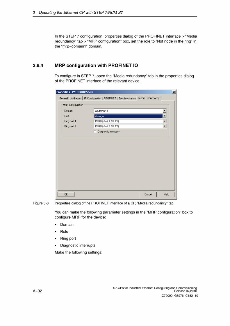
3 Operating the Ethernet CP with STEP 7/NCM S7
A−92S7-CPs for Industrial Ethernet Configuring and Commissioning
Release 07/2010
C79000−G8976−C182−10
In the STEP 7 configuration, properties dialog of the PROFINET interface > “Mediaredundancy” tab > “MRP configuration” box, set the role to “Not node in the ring” inthe “mrp−domain1” domain.
3.6.4 MRP configuration with PROFINET IO
To configure in STEP 7, open the “Media redundancy” tab in the properties dialogof the PROFINET interface of the relevant device.
Figure 3-8 Properties dialog of the PROFINET interface of a CP, “Media redundancy” tab
You can make the following parameter settings in the “MRP configuration” box toconfigure MRP for the device:
� Domain
� Role
� Ring port
� Diagnostic interrupts
Make the following settings:

3 Operating the Ethernet CP with STEP 7/NCM S7
A−93S7-CPs for Industrial Ethernet Configuring and CommissioningRelease 07/2010
C79000−G8976−C182−10
Domain
Select the name “mrpdomain 1” from the drop−down list.
All devices configured in a ring with MRP must belong to the same redundancydomain. A device cannot belong to more than one redundancy domain.
If you leave the setting for “Domain” as the factory set “default−mrpdomain”, thefactory settings for “Role” and “Ring ports” also remain active.
The MRP settings remain in effect following a restart of the device or following apower down and hot restart.
Role
The choice of role depends on the following uses.
� You want to use MRP in a ring topology only with Siemens devices and withoutmonitoring diagnostic interrupts:
Assign all devices to the “default−mrpdomain”.The device that actually takes over the role of redundancy manager, isnegotiated by Siemens devices automatically.
� You want to use MRP in a ring topology that also includes non−Siemensdevices or you want to receive diagnostic interrupts relating to the MRP statusfrom a device (see “Diagnostic interrupts”):
− Select the “Manager” role for one device (and one only) that will beredundancy manager in the ring.
− With all other devices in the ring topology, select the role of “Client”.
Notice
To ensure problem−free operation when using a non−Siemens device as theredundancy manager in the ring, make sure that you assign the fixed role of“Client” to all other devices in the ring, before you close the ring. Otherwise, theremay be circulating data frames that will cause a failure in the network.
� You want to disable MRP:
Select the option “Not node in the ring” if you do not want to operate the devicewithin a ring topology with MRP.
Notice
If you reset to the factory settings, the MRP role of the device is also reset. If youare operating a non−Siemens device as the redundancy manager in the ring, thismay cause loss of the data traffic.

3 Operating the Ethernet CP with STEP 7/NCM S7
A−94S7-CPs for Industrial Ethernet Configuring and Commissioning
Release 07/2010
C79000−G8976−C182−10
Ring port 1 / ring port 2
Notice
If you reset to the factory settings, the ring port settings are also reset. With theappropriate attachment, a ring node that was previously correctly configured cancause circulating frames and a loss of the data traffic.
Here, select the port you want to configure as ring port 1 and ring port 2.
The drop−down list shows the selection of possible ports for each device type. Ifthe ports are specified in the factory, the boxes are grayed out.
Diagnostic interrupts
Select the “Diagnostic interrupts” option, if you want diagnostic interrupts relating tothe MRP status to be output on the local CPU.
The following diagnostic interrupts can be generated:
� Wiring or port error
Diagnostic interrupts are generated if the following errors occur at the ringports:
− A neighbor of the ring port does not support MRP.
− A ring port is connected to a non−ring port.
− A ring port is connected to the ring port of another MRP domain.
� Interruption / return (redundancy manager only)
If the ring is interrupted and when the original configuration returns, diagnosticinterrupts are generated.
The occurrence of both interrupts within 0.2 seconds indicates an interruption inthe ring.

3 Operating the Ethernet CP with STEP 7/NCM S7
A−95S7-CPs for Industrial Ethernet Configuring and CommissioningRelease 07/2010
C79000−G8976−C182−10
3.7 “Substitute objects” in the STEP 7 project
Overview
Communication connections can be configured fully when the communicationspartners are available in the current project. For the stations on the Ethernetsubnet, whose configuration data were not created in STEP 7 or whoseconfiguration data are not managed in the currently active project, the followingsubstitute objects can be created in the project:
� SIMATIC S5 stations
� PG/PC
� Other stations
− for devices of other manufacturers
− for SIMATIC S7 stations in another project (not necessary in a multiproject)
Note
Instead of creating substitute objects, you can also configure unspecifiedconnections for connections to the stations listed above.
In the Properties dialog of these connections, you must then specify the fullpartner address. These partners do not appear in the NetPro plant view.
Ethernet subnet (1)
Plant
“Production 1”
SIMATIC S5
Third-party
device
S7-400/1
S7-400/5
Plant
“Production 2”
S7-400/2 S7-400/4
S7-400/3
PC/PG

3 Operating the Ethernet CP with STEP 7/NCM S7
A−96S7-CPs for Industrial Ethernet Configuring and Commissioning
Release 07/2010
C79000−G8976−C182−10
Procedure
To enter a substitute object in the project, following the steps below:
1. Select the project in the SIMATIC Manager.
2. Select Insert � Station � and then as necessary Other Station, PG/PC or SIMATIC S5
Possible result: the selected object is created in the project.
Figure 3-9 Project with substitute objects configured
Attaching non-S7 stations to the subnet
The next step is to assign the substitute objects to the subnet, as follows:
1. Select the required object in the project and select Edit � Object Properties.
2. In the Properties dialog box that is displayed select the “Interfaces” tab andclick the “New” button (for example “Other Station”.
Result: The New Interface − Type Selection dialog box is displayed.

3 Operating the Ethernet CP with STEP 7/NCM S7
A−97S7-CPs for Industrial Ethernet Configuring and CommissioningRelease 07/2010
C79000−G8976−C182−10
Figure 3-10 Selecting the Subnet Type for “Other Station” (Example)
3. Select a subnet.
Result: The “Properties − Ethernet Interface” dialog is displayed. Here, you canselect the subnet, connect the station to the network and set the address (MAC,IP). All the SIMATIC stations in the project can establish communicationrelationships to this substitute object.
The addresses (MAP/IP) configured for the substitute object here must also be seton the station using the appropriate tool, for example COM 1430.
3 Operating the Ethernet CP with STEP 7/NCM S7
A−98S7-CPs for Industrial Ethernet Configuring and Commissioning
Release 07/2010
C79000−G8976−C182−10
3.8 Configuring communication services
Setting up connections
You must set up connections for the connection-oriented services supported by theIndustrial Ethernet CP, see also the Table in Section 1.2.
� S7 connectionssee the STEP 7 user manual /6/
� ISO transport connectionssee Section 5.4
� ISO-on-TCP connectionssee Section 5.5
� TCP connectionssee Section 5.6
� Connections for UDPsee Section 5.7
� E−mail connections(see Chapter 7)
� Interconnections for PROFINET CBA communicationsee manual Component based Automation − configuring plants with SIMATICiMap/8/
The information in the STEP 7 user manual /6/ in the chapter “CreatingCommunication Connections Between Two Programmable Modules” also appliesto the additional types of connection possible with the CPs.
You will find this information in the online help with integrated in STEP 7 You canopen this with Help � Contents. Select the topic “Configuring Connections andData Exchange.
3 Operating the Ethernet CP with STEP 7/NCM S7
A−99S7-CPs for Industrial Ethernet Configuring and CommissioningRelease 07/2010
C79000−G8976−C182−10
3.9 Assigning addresses for the first time
Meaning of the address assignment − MAC address and IP address
The CP ships with one or two fixed MAC addresses. Without further configuration,the device can only be accessed over the Ethernet port using these MACaddresses.
In its original state, you can already use the following functions via the CP usingthe ISO protocol and the factory-set MAC address:
� Download the defined configuration to the CP or CPU
� Run diagnostics on the CP or CPU
Before you can download defined configuration data to the device using an IPaddress, you must first assign an IP address to the CP.
Assigning the address − options and recommendations
There are three ways of assigning this address in STEP 7:
� Addressing by selecting the target system in the SIMATIC Manager
This variant is supported only for the PROFINET interface. It allows you toassign the address without having to set up a STEP 7 project. This is useful, forexample, if you want to download defined configuration data you created offlineto the S7 station.
This is described in Section 3.9.1.
� Addressing using the properties dialog in HW Config or NetPro
This option assumes that the CP was networked in STEP 7. The advantage ofthis method is that the IP parameters set during configuration in STEP 7 /NetPro can be used.
In the “Addressing” tab, you will need to assign the CP the previouslyconfigured IP address and the IP parameters of the Ethernet or PROFINETinterface.
This is necessary before the configuration data can be downloaded to the CPover Ethernet.
This is described in Section 3.9.2.
� Downloading configuration data using the ISO protocol
A further variant is to download project engineering data with a defined IPaddress over the ISO protocol (see above); this applies to CPs that support theISO protocol.
3 Operating the Ethernet CP with STEP 7/NCM S7
A−100S7-CPs for Industrial Ethernet Configuring and Commissioning
Release 07/2010
C79000−G8976−C182−10
Requirements
Before you can use the addressing described here, the CP must be obtainableonline, which means:
� An attachment to the Ethernet LAN must already exist; there must be norouters between subnets in the path.
� The Ethernet port of your PG/PC must be accessible to STEP 7.
Notice
The options for assigning an address as described here are available only if youhave a module that can be reached using the default MAC address; such modulesmust support the PST (Primary Setup Tool) function. Please refer to theinformation in the relevant manual /1/.
On CPs with an additional gigabit interface, the PST tool can only be used on thePROFINET interface.
3.9.1 Addressing by selecting the target system in the SIMATICManager
Follow the steps below to assign the IP address the first time:
1. Open the SIMATIC Manager
2. Select the menu command “PLC” � “Edit Ethernet Node”.
3. Start a network search for available modules by selecting the “Browse...”button.
4. Select the CP with the matching MAC address from the components listed.
5. Enter the required IP parameters and assign them to the CP.
Result:The CP is now accessible on Industrial Ethernet using the IP address.
Note
You will find further detailed information on this procedure in the STEP 7 onlinehelp.

3 Operating the Ethernet CP with STEP 7/NCM S7
A−101S7-CPs for Industrial Ethernet Configuring and CommissioningRelease 07/2010
C79000−G8976−C182−10
Alternative procedure
You can also follow the steps outlined below in the SIMATIC Manager:
1. Use the menu command PLC� Display Accessible Nodes to display thenodes that you can access over Industrial Ethernet.
2. Select the required node in the list displayed.
3. Then select the menu command PLC� Ethernet Address.
Result: The previously selected node is entered directly into the “Addressing”dialog. You cannot modify the MAC address of the node.
4. Enter the required IP parameters and assign them to the CP (see above underSTEP 5.).
Result:The CP is now accessible on Industrial Ethernet using the IP address.
3.9.2 Addressing using the properties dialog in HW Config or NetPro
Configure the IP address for a newly inserted CP
1. Open the SIMATIC Manager and your STEP 7 project.
2. Open HW Config by double−clicking on the “Hardware” object
3. Insert the required CP in the open S7 station.
When you create the CP, the properties dialog of the Ethernet interface isopened with the “Parameters” tab in which you can network the device andassign the IP address.
4. Edit the MAC address and, if required, the IP parameters in the open propertiesdialog of the Ethernet interface.
5. Select the Ethernet subnet with which you want to connect the CP in the“Subnet” box.
6. Confirm with “OK”.
The properties dialog closes and the CP is networked.
7. Save your project.
Assigning the IP address to the CP for the first time
1. Open the “Select Station Address” dialog in HW Config or NetPro using the“PLC” > “Download to Module” menu.
2. Start a network search for available modules by selecting the “Update” button.
For CPs with multiple interfaces, only the PROFINET interface is displayed.
3. Select the CP with the matching MAC address from the components listed.
The configured IP address is displayed.

3 Operating the Ethernet CP with STEP 7/NCM S7
A−102S7-CPs for Industrial Ethernet Configuring and Commissioning
Release 07/2010
C79000−G8976−C182−10
4. Assign the IP parameters taken from the networking to the CP by clicking the“OK” button.
Result:After downloading the configuration data, the CP can be reached on IndustrialEthernet using the IP address.
Note
You will find further detailed information on this procedure in the STEP 7 onlinehelp.

3 Operating the Ethernet CP with STEP 7/NCM S7
A−103S7-CPs for Industrial Ethernet Configuring and CommissioningRelease 07/2010
C79000−G8976−C182−10
3.10 Downloading the configuration data to the target system
Principle
The configuration data of the Ethernet CP are downloaded from the hardwareconfiguration. All the configuration data of the S7 station are downloaded includingthe central configuration, all relevant DP master systems and all parametersettings.
The data of the configured connections must also be downloaded, see below.
Type of interface
You can download the configuration data to the S7 station on the following paths(interfaces):
� MPI interface
You can use this interface to download configuration data or when assigning aMAC/IP address for the first time (node initialization − for details, refer to themanual /1/ “Assigning Addresses for the First Time”).
� Industrial Ethernet
Here, you use the PG mode of the Ethernet CP in the S7 station (see alsoSection 1.3).
Depending on the PG/PC interface used by the station on which you createyour configuration, you can download the defined configuration data to the S7station over the TCP/IP interface or over the ISO interface of STEP 7.
− When you download over the IP interface, the CP must already have beenassigned an IP address; refer to Chapter 3.9.
− When you download over the ISO interface, you can use the preset MACaddress. However, please note the following:
Note
If you want to download the configuration data over the ISO interface to a CP withan unchanged, factory-set MAC address and you have configured a different MACaddress in your STEP 7 project, you must start the download in NetPro or HWConfig; this is the only way you will be prompted to enter the current MACaddress. The SIMATIC Manager, on the other hand, aborts the download if thetarget station cannot be reached.

3 Operating the Ethernet CP with STEP 7/NCM S7
A−104S7-CPs for Industrial Ethernet Configuring and Commissioning
Release 07/2010
C79000−G8976−C182−10
Procedure
To download the configuration data to the S7 station, follow the steps outlinedbelow:
1. Open the “Set PG/PC Interface” dialog box in the Windows Control Panel.
2. Set the PG/PC interface according to the CPs available on your PG andaccording to the bus attachment (interface parameter assignment used).
For more detailed information, refer to the integrated help system.
3. Change the CPU to the STOP mode (regardless of the type of interface − seeabove).
4. Select the menu command PLC � Download to Module.
STEP 7 then guides you through dialog boxes. Note the additional information inthe “STEP 7 User Manual”, Chapter “Configuring and Assigning Parameters toModules” /6/.
Disabling the ISO protocol in the configuration (MAC address invisible)
If you disable the use of the ISO protocol in the properties dialog of the Ethernetinterface when configuring the CP, the CP can still be reached using the defaultMAC address. You cannot, however, then configure any ISO transport connectionsor S7 connections over ISO connections. If the ISO protocol is disabled, theconfigured MAC address is not visible in the properties dialog.
Non-volatile storage of the project engineering data (on CPs with datamanagement)
You can download the configuration data step-by-step or all at once. If youdownload step-by-step, you will be prompted to start the download functionseparately for each module. You must select this method if you want to save theconfiguration data in non-volatile memory on the Ethernet CP. In this case, selectthe “Copy to ROM” button in the “Download” dialog for the CP.
Downloading the configured connections
To download configured connections, you use a corresponding download functionin the connection configuration (NetPro).
Notice
If you have assigned a new address to the Ethernet CP or have configuredconnections, you must always download the connection configuration again.
Remember that you also make suitable address adaptations for the other stationsor “substitute objects”.
F1

3 Operating the Ethernet CP with STEP 7/NCM S7
A−105S7-CPs for Industrial Ethernet Configuring and CommissioningRelease 07/2010
C79000−G8976−C182−10
Relocating the CP in the Hardware Configuration
If you are using communication services with configured connections, theconnection IDs also identify the slot of the CP. If you “drag” a CP you have alreadyconfigured to a different slot, note the following:
Notice
If you drag the CP to a different slot, the data of the connection configuration areautomatically updated. The data of the connection configuration must, however, bedownloaded again!
�

A−106S7-CPs for Industrial Ethernet Configuring and Commissioning
Release 07/2010
C79000−G8976−C182−10
4 SEND/RECEIVE Interface in the User Program
This chapter explains the following:
� How data is sent and received;
� Which data areas can be used on the S7 CPU.
� How to program the SEND/RECEIVE interface in the user program.
You will find further information in the following sources:
� When programming and configuring communication nodes for connections (forexample, SIMATIC S5 with CP 1430 TCP, PC with CP 1613), please read theappropriate manual.
� The FCs for programming the connections are described in /10/
� How to configure communications connections with NCM S7 is explained inChapter 5.
� How to program communications connections via the interface in the userprogram is explained in /10/.
Sample programs:
Sample configurations and programs are available for the SEND/RECEIVEinterface described here:
� In the sample project PROJECT_ETHERNET that you can start immediatelyafter installing STEP 7 / NCM S7; for a description, refer to the “Primer” /3/.
� Sample program for the SEND/RECEIVE interface with the blocks FC5(AG_SEND) and FC6 (AG_RECV) for S7−300:
http://support.automation.siemens.com/WW/view/en/17853532
� Sample program for the SEND/RECEIVE interface with the blocks FC50(AG_LSEND) and FC60 (AG_LRECV) for S7−400:
Here, you will also find a collection of further entries and sample projects andprograms for S7 CPs for Industrial Ethernet.
http://support.automation.siemens.com/WW/view/en/18513371
� The Quick Start CD that can be ordered separately is a treasure-trove ofsample programs and configurations.
You can order this directly over the Internet at:
http://support.automation.siemens.com/WW/view/en/21827955

4 SEND/RECEIVE Interface in the User Program
A−107S7-CPs for Industrial Ethernet Configuring and CommissioningRelease 07/2010
C79000−G8976−C182−10
4.1 How the SEND/RECEIVE interface on the CPU works
FCs
The following blocks (FCs) are available for handling communication onconnections:
� AG_SEND (FC 5) / AG_LSEND (FC 50) / AG_SSEND (FC 53)The block transfers the user data from the specified user data area for transferto the Ethernet CP.
� AG_RECV (FC 6) / AG_LRECV (FC 60) / AG_SRECV (FC 63)The block enters the received user data in the user data area specified in thecall.
The schematic below illustrates the procedure: Using the FCsAG_SEND/AG_LSEND/AG_SSEND and AG_RECV/AG_LRECV/AG_SRECV, theuser program instructs the Ethernet CP to send or receive data on the configuredconnection.
Communicationsconnection
Ethernet CPCPU
STEP 7user program
Userdata buffer
CPdatabase
Ethernet node SIMATIC S7
receive
send
User data areas
AG_RECV
AG_SEND
Figure 4-1 Interaction of the CPU and Ethernet CP when using connections

4 SEND/RECEIVE Interface in the User Program
A−108S7-CPs for Industrial Ethernet Configuring and Commissioning
Release 07/2010
C79000−G8976−C182−10
Amounts of data and configuration limits
The Ethernet CP can transfer the following amounts of data per job (send orreceive) over a connection:
Table 4-1
ISO Transport ISO Transport TCP UDP
send
AG_SEND *)
AG_LSEND **)
AG_SSEND ***)
8192 bytes
8192 bytes
1452 bytes
8192 bytes
8192 bytes
1452 bytes
8192 bytes
8192 bytes
1452 bytes
2048 bytes
2048 bytes
1452 bytes
receive
AG_RECV *)
AG_LRECV **)
AG_SRECV ***)
8192 bytes
8192 bytes
1452 bytes
8192 bytes
8192 bytes
1452 bytes
8192 bytes
8192 bytes
1452 bytes
2048 bytes
2048 bytes
1452 bytes
*) With older versions of FC AG_SEND / AG_RECV (up to V3.0), the data area isalways restricted to a maximum of 240 bytes.
With the S7−400, the data area of AG_SEND / AG_RECV is restricted to amaximum of 240 bytes.
**) Only with S7−400
***) Only with S7−400 with CPUs as of version V5.1 and the following CPs:
− CP 443−1 (as of 6GK 7 443−1EX20...)
− CP 443−1 Advanced (as of 6GK 7 443−1GX20...)
4 SEND/RECEIVE Interface in the User Program
A−109S7-CPs for Industrial Ethernet Configuring and CommissioningRelease 07/2010
C79000−G8976−C182−10
4.2 Programming the SEND/RECEIVE interface
Principle of job and data transfer
The user program triggers the transfer of the user data areas with FC calls andmonitors the transfer by evaluating the return codes of the FCs.
Among others, the following parameters are transferred when the FCs are called:
� The number of the connection (ID)
� The location of the user data area in the CPU
You will find detailed information on the call interface in /10/.
Purpose of the FCs
Calling the function blocks has the following effects:
� The user data area is transferred to the Ethernet CP or received from theEthernet CP.
� The execution of the job is confirmed positively or negatively in a statusmessage.
Follow the steps below:
Program the SEND/RECEIVE interface in the user program as follows:
1. Use the following functions (FCs) for data transmission on connections:
− AG_SEND / AG_LSEND / AG_SSEND for transferring the user data area tothe Ethernet CP
− AG_RECV / AG_LRECV / AG_SRECV for entering data received from theEthernet CP in the user data area
2. Evaluate the following bits in the FCs:
− for AG_SEND / AG_LSEND / AG_SSEND the parameters DONE, ERROR,STATUS;
− for AG_RECV / AG_LRECV / AG_SRECV the parameters NDR, ERROR,STATUS;
Notice
Connection numbers (IDs) must be taken from the configuration whenprogramming. To ensure correct parameter settings for the block calls, The LAD/STL/FBD editorin STEP 7 provides you with the option of accepting all the relevant parametersfrom the hardware configuration (HW Config) and from the connectionconfiguration. For more information, refer to /10/

4 SEND/RECEIVE Interface in the User Program
A−110S7-CPs for Industrial Ethernet Configuring and Commissioning
Release 07/2010
C79000−G8976−C182−10
Calling FCs in the CPU program
One possible sequence for FCs in conjunction with the organization and programblocks in the CPU cycle is illustrated in the following diagram.
ÇÇÇÇÇÇÇÇÇÇÇÇÇÇÇÇ
ÍÍÍÍÍÍÍÍÍÍÍÍÍÍÍÍ
AG_RECV
ÍÍÍÍÍÍÍÍÍÍÍÍÍÍÍÍÍÍ
AG_SEND
AG_SEND
Read in the receiveddata of theconnection
Transfer send datafor the connection
Write PIQ
OB
ÇÇÇÇÇÇÇÇÇÇÇÇÇÇÇÇÇÇÇÇÇÇÇÇÇÇÇ
Legend: Sequence of the CPU cycle
AG_RECV
AG_RECV
Communicationsconnection
ÇÇÇÇÇÇÇÇÇÇÇÇÇÇÇÇÇÇÇÇÇÇÇÇÇÇÇÇ
ÍÍÍÍÍÍÍÍÍÍÍÍÍÍÍÍÍÍÍÍÍÍÍÍÍÍÍÍÍÍÍÍÍÍÍ
AG_SEND
User program
The different shading shows whichconnections and FC blocks belongtogether.
ÇÇÇÇ
ÍÍÍÍ
Read PII
Communicationsconnection
Communicationsconnection
Figure 4-2 Typical sequence of function calls in the CPU cycle
The following points are illustrated by the diagram:
� The user program consisting of any number of blocks (OBs, FBs or FCs −> seealso /6/ accesses several connections (Figure 4-2 illustrates three connections).
� At various points (event and program-controlled) the user program sends data

4 SEND/RECEIVE Interface in the User Program
A−111S7-CPs for Industrial Ethernet Configuring and CommissioningRelease 07/2010
C79000−G8976−C182−10
on a connection using the AG_SEND call.
� At various points in the CPU cycle, the user program accepts the data receivedon the connection using an AG_RECV call.
Note
The blocks can be called more than once in a cycle for one communicationconnection.

4 SEND/RECEIVE Interface in the User Program
A−112S7-CPs for Industrial Ethernet Configuring and Commissioning
Release 07/2010
C79000−G8976−C182−10
4.3 Data exchange S7 CPU <−> Ethernet CP
The Ethernet CP processes the send and receive jobs independent of the CPUcycle and requires one transmission time. The interface to the user program withthe FCs is synchronized by an acknowledgment. Two situations must be distinguished:
� The CPU cycle is faster than the transmission time.
� The CPU cycle is slower than the transmission time.
Note
Please refer to the flow charts of the functions (FCs) in /10/. These charts showyou how to supply and handle the SEND/RECEIVE interface in the user programfor problem−free data exchange.
Remember the points below about the CPU cycle and transmission time.
FC calls faster than the transmission time
If a block is called again in the user program before data were transferred orreceived, the procedure is as follows on the interface of the FCs:
� AG_SEND/AG_LSEND/AG_SSEND:No further job is accepted until the transmission of the data on the connectionhas been acknowledged by the Ethernet station. During this time, the userprogram receives the message “job active” until the Ethernet CP can accept thenext job on the same connection.
� AG_RECV/AG_LRECV:The job is acknowledged with the message “no data available yet” if there areno received data on the Ethernet CP. The user program receives this messagein the CPU cycle until the Ethernet CP has received data again on theconnection.
FC calls slower than the transmission time
If a block is called again before the data were completely transferred or received,the procedure is as follows on the interface of the FC blocks:
� AG_SEND/AG_LSEND/AG_SSEND:The job is positively acknowledged. The Ethernet CP is ready to receive a newsend job (at the earliest however with the next call).
� AG_RECV/AG_LRECV/AG_SRECV:The job is acknowledged with “New Data Received” when the data have beentransferred to the user program. Following this, the FC call can be repeated.

4 SEND/RECEIVE Interface in the User Program
A−113S7-CPs for Industrial Ethernet Configuring and CommissioningRelease 07/2010
C79000−G8976−C182−10
Notice
Remember that resource shortages can occur if the processing speeds on thesender and receiver are not the same (sender faster than receiver).
The sender receives a message from the FCs if problems occur (“No resources onthe destination station”). (not with AG_SRECV)

4 SEND/RECEIVE Interface in the User Program
A−114S7-CPs for Industrial Ethernet Configuring and Commissioning
Release 07/2010
C79000−G8976−C182−10
4.4 Additional information
4.4.1 Programming data transfer on TCP connections
Purpose of TCP connections
TCP connections should be used above all for connections to systems of adifferent type if they do not support the RFC1006.
For communication between devices of the SIMATIC family, you should use themore convenient ISO-on-TCP connections! The following sections explain certainspecial points to note.
Special features
� Block types (FC calls)
Use only the following functions (FCs) for data transmission:
− AG_SEND (FC 5), AG_LSEND (FC 50) or AG_SSEND (FC 53)
− AG_RECV (FC 6), AG_LRECV (FC 60) or AG_SRECV (FC 63)
For older modules, note the information in /10/ and /11/.
� Frame length
On the TCP connections, the protocol contains no information about the end ofa message and start of a new message.
The receiving station must therefore know how many bytes belong to amessage and transfer an ANY pointer corresponding exactly to this length whenFC AG_RECV/AG_LRECV is called. Example: if 100 bytes of data are alwaysreceived, the ANY pointer could appear as: P#DB100.DBX 0.0 Byte 100. (Thisdoes not apply to FC AG_SRECV, this is always called with the maximumlength.)
If you want to receive data with a variable length, follow the steps below:
Include information on the length of the user data in the frame before the actualuser data start. Initially, you should only evaluate the length information on thereceiving station. Fetch the appropriate length of user data in another receivejob by specifying an ANY pointer of the required length on the FC interface forfetching the actual user data.

4 SEND/RECEIVE Interface in the User Program
A−115S7-CPs for Industrial Ethernet Configuring and CommissioningRelease 07/2010
C79000−G8976−C182−10
4.4.2 Recommendations for use with a high communications load
Overview
The points below relate to the Ethernet CPs and will help you to avoid overloadsituations on your CPU.
In particular when you replace an older CP with a newer CP and are thenconfronted with overload problems, you should check your application for thepitfalls outlined below.
Known problems
� The functions for sending and receiving (FC*5/FC6, FC 50/60 or FC 53/63) areoften called cyclically in OB1. This leads to constant communication betweenthe CPU and CP. As a result, other types of communication such as PGfunctions cannot be executed or only very slowly.
� HMI systems access data of the CPU too often using S7 functions. This slowsdown communication generally and there may be a lack of resources whenSEND/RECEIVE FCs are called cyclically in OB1.
Remedy
The recommendations below will help to avoid these situations:
� Do not call communication blocks cyclically in OB1!
Communication should be called time-controlled in a suitable cyclic-interruptOB. The call interval of this OB should be significantly higher than the averagecycle time of OB1.
� You should set a minimum cycle time that is higher than the average runtime ofOB1. This frees resources for communication on the CPU. This is, for example,a remedy for existing applications when communication already takes placecyclically in OB1.
� If necessary, reduce the time taken for communication processing on the CPUby changing the parameters set for “cyclic load due to communication” in theproperties dialog of the CPU.
�

A−116S7-CPs for Industrial Ethernet Configuring and Commissioning
Release 07/2010
C79000−G8976−C182−10
5 Configuring Communication Connections
This chapter explains the following:
� The general aspects of configuring communication connections
� How to configure ISO transport connections, ISO−on−TCP, UDP and TCPconnections
� How to use the connection configuration functions to specify communicationpartners that exchange data via UDP
You will find a description of the connection−specific properties dialogs in thefollowing sections:
� Configuring ISO transport connection properties
� Configuring ISO−on−TCP connection properties
� Configuring TCP connection properties
� Configuring UDP connection properties
You will find further information in the following sources:
� For the properties of the configurable connection types, refer to Section 1.5
� There are situations in which communication connections are not set up overthe configuration interface of STEP 7 but program−controlled by certainapplications; see also /10/.
� For the properties of the configurable connection type E−mail, refer to Chapter7
� You will find information on the numbers of connections and amounts of data inSection 4.1.
� For information on configuring connections, in particular the S7 connections,refer to the integrated basic online help of STEP 7. You can open this with Help� Contents.

5 Configuring Communication Connections
A−117S7-CPs for Industrial Ethernet Configuring and CommissioningRelease 07/2010
C79000−G8976−C182−10
5.1 Procedure
Initial situation
The steps described here assume the following:
1. You have created the local S7 station and the required partner stations in yourSTEP 7 projects (refer to the description in Chapter 3).
2. You have clarified the other station types with which connections must beestablished. You create substitute objects for these station types in yourSTEP 7 projects.
Setting up connections and using them in the user program
The following steps are necessary to operate connections on the SIMATIC S7 PLCwith the Ethernet CP:
Program the SEND/RECEIVEinterface in the user program.
(refer to the information in Section 4.2and the detailed FC description in/10/).
ProgrammingCreate new connections.
(see Section 5.3.1)
Download connection configurationsand user programs to the S7 station.
Configure connection properties.
(see Sections 5.4 to 5.9)
Configuration
necessary stepsoptional steps
Legend:

5 Configuring Communication Connections
A−118S7-CPs for Industrial Ethernet Configuring and Commissioning
Release 07/2010
C79000−G8976−C182−10
5.2 Possible connection configurations
Communication connections are possible between the communication partnersshown in the diagram below.
The communication partners can be in the same project or distributed in thesubprojects of a multiproject.
Connections to communication partners outside a project are configured using theSTEP 7 object “Partner other project” or using substitute objects such as ”Otherstations” or SIMATIC S5.
S7 − 400
S7 − 300Ethernet CP
Ethernet CP
Subnet 1
SIMATIC S5
S7 − 400Ethernet /IT−CP
Ethernet CP
PG/PC with Ethernet CP
Ethernet CP
S7 − 400
WAN*LAN *
Subnet 2
Ethernet CP
Other station with Ethernet attachment
only TCP/IP
Figure 5-1 Possible connections

5 Configuring Communication Connections
A−119S7-CPs for Industrial Ethernet Configuring and CommissioningRelease 07/2010
C79000−G8976−C182−10
Organization in a multiproject
If interproject subnets are configured, you can also configure connections oversuch subnets. The endpoints of these connections can be located in differentprojects.
STEP 7 supports you both when creating interproject connections within amultiproject as well as when synchronizing connections that were configuredwithout a multiproject context.

5 Configuring Communication Connections
A−120S7-CPs for Industrial Ethernet Configuring and Commissioning
Release 07/2010
C79000−G8976−C182−10
5.3 Connections
Characteristics of a connection
A communication connection allows program−controlled communication betweentwo nodes on Industrial Ethernet with the following characteristics:
� The data transfer is bi−directional, in other words, it is possible to transmit andreceive on the connection simultaneously.
� Both stations have the same rights, in other words, each station can trigger thesend and receive procedures in response to events.
� The address of the communication partner is specified in the configuration.
Exceptions to this are:
− free UDP connections
Here, the address is specified at the FC interface in the user program.
− The communications connection programmed in the user program usingFB55 (see /10/)
Communicationconnection
Ethernet CP
Ethernetnode
SIMATIC S7 station with Ethernet CP
receive
send receive
send
Ethernetnode
receive
sendreceive
sendCommunicationconnection
Figure 5-2 Sending and receiving via one communication connection
Note
The term “connection” is also used here for UDP. Reason: During configuration(just as in TCP) the communication partners are assigned to each other andtherefore logically “connected”. In actual fact, with UDP there is no explicitconnection establishment between communication partners.

5 Configuring Communication Connections
A−121S7-CPs for Industrial Ethernet Configuring and CommissioningRelease 07/2010
C79000−G8976−C182−10
Amounts of data
Refer to the manual supplied with the Ethernet CP /1/ for the number ofcommunications connections supported by the specific Ethernet CP. The numberof connections per station can be increased by adding more CPs.
For information on the amounts of data transferred by the Ethernet CP per job(send or receive) over a connection, refer to Table 4-1.
Tasks of the Ethernet CP
When handling the data transfer on a connection, the Ethernet CP has thefollowing tasks:
� When receiving
Receiving data from Ethernet and transferring it to the user data area on theCPU.
� When sending
Taking data from the user data area on the CPU and sending the data viaEthernet.
The connection is established automatically as soon as the partner is obtainable.
For a free UDP connection, the following functions are also necessary in additionto those above:
� When receiving
Entry of the sender of the message in the job header.
� When sending
Evaluation of the job header and addressing the partner
Requirements for configuring connections
� The Ethernet CP was configured in hardware configuration (HW Config) andnetworked with an Ethernet subnet.
� As a bus node, the Ethernet CP has an address.
Notice
All stations not in the STEP 7 project must be configured with substitute objects(for example as “SIMATIC S5” or “Other stations”).
or
Use the “unspecified” partner type when you create the connection.

5 Configuring Communication Connections
A−122S7-CPs for Industrial Ethernet Configuring and Commissioning
Release 07/2010
C79000−G8976−C182−10
5.3.1 New connection
Principle
When you create new connections, you start from entered and networked stations.A connection is then configured starting from a station or CPU in the current S7project and then selecting a destination station.
Due to the networking, the node addresses (MAC or IP addresses) of the twostations are already decided. The local/remote TSAPs (Transport Service AccessPoint) or ports at both ends of the connection are automatically assigned defaultvalues.
If the partner station is a station outside the current project or a non−S7 station,the remote TSAPs (Transport Service Access Point) or ports must be specified inthe Properties dialog of the connection.
The endpoint of the connection to a SIMATIC S7 station is always a CPU. Aseparate connection table is created for each CPU and displays the connectionpartner and types of connections.
Creating a new connection
To configure a new connection, the stations and their CPs must be configured andnetworked in the S7 project. To create a new connection, follow the steps below:
In NetPro, follow the steps below:
1. In NetPro, select the station or the CPU in the station from which you want toestablish the connection.
2. Select the menu command Insert � New Connections (also available with theright mouse button!).
Result: The ”New Connection” dialog opens on the screen.
3. Select the partner station to which you want to establish a connection (if severalCPUs exist, please select the required CPU).
4. Select the connection type you want to use (for example ISO transportconnection) in the “Type” box
When you confirm your input with Apply, the new connection is created and the”New Connection” dialog box remains open. This allows you to create furtherconnections without needing to reopen the dialog box. The connection table isupdated at the same time.
When you click OK, the connection is entered in the list, the dialog is terminatedand the display in the main dialog is updated.
If you click Cancel, the dialog is terminated and the connection is not entered inthe list.

5 Configuring Communication Connections
A−123S7-CPs for Industrial Ethernet Configuring and CommissioningRelease 07/2010
C79000−G8976−C182−10
Handling connections in a multiproject
Interproject connections to a specified partner (for example a CPU) are createdjust like connections within a project (identical procedure). The dialog for selectingthe connection partner has been extended and allows you not only to select theendpoint (module) but also the project within a multiproject to which the endpointbelongs.
The consistency of interproject connections is retained when you work with theprojects of the multiproject:
� Interproject connections within a multiproject are implicitly broken when aproject is taken out of the multiproject for distributed editing and the connectionpartner is located in the removed project.
� When the removed project is returned to the multiproject, STEP 7 automaticallymerges the broken connections consistently.
Connections to non−S7 stations using substitute objects
If you want to configure connections to devices or stations that are not S7 stations,select a station of the type “SIMATIC S5”, “PC/PG” or “Other Station” as thedestination station.
By creating these stations in NetPro and networking them, you have alreadyspecified the node addresses (MAC or IP addresses) of the two stations. You mustspecify the TSAP (Transport Service Access Point) for the destination station.
Notice
Connections to non−S7 stations (for example SIMATIC S5) are generated asincompletely specified connections; in other words, the remote TSAP or port isempty. These connections must be specified in the Properties dialog.
5 Configuring Communication Connections
A−124S7-CPs for Industrial Ethernet Configuring and Commissioning
Release 07/2010
C79000−G8976−C182−10
5.3.2 Connections to partners in other projects
There are various ways of creating connections to partners configured in otherSTEP 7 projects or with other tools outside the current STEP 7 project:
� Connections using substitute objects such as “SIMATIC S5”, “PC/PG” ,“SIMATIC PC Station” or “Other Station”.
This method is described in the section above.
� Unspecified connections
� STEP 7 object ”Partner in other project” (multiproject)
With this method, a connection is reserved in both subprojects that can besynchronized later by the system when the partner project is included in themultiproject.
In both projects, the same connection name must be configured in theproperties of the connection. The connection name is used as a textualreference when the projects are merged. Based on the connection name it ispossible to assign the connection partner and synchronize the connectionproperties.
Before the projects are merged, such connections are ”unspecifiedconnections” in terms of addressing; in other words, the partner addressesremain empty.
Unspecified connections
Connections to an as yet unknown device (for example a diagnostic unit) areconfigured as “unspecified” connections. They can be specified later in theProperties dialog.
You can create an unspecified connection simply by selecting station “unspecified”for the connection partner when you create the connection. The unspecifiedconnection can be used in various ways (explained below based on the example ofan ISO−on−TCP connection; ISO transport, TCP and S7 connections areanalogous):
� Declare readiness for communication − passive connection establishment
The connection establishment is set to passive (see settings in the Generaltab).
The address setting for the ISO−on−TCP connection is then as follows: The remote IP address and the remote TSAP are empty, in other words, theyare not relevant for the CP. When the connection is established, any partner isaccepted (partner = connection name that addresses the CP with the correct IPaddress and TSAP).
It is also possible to use a partial specification; in other words, communicationis permitted with any partner that matches the specified TSAP.
5 Configuring Communication Connections
A−125S7-CPs for Industrial Ethernet Configuring and CommissioningRelease 07/2010
C79000−G8976−C182−10
� Connection to a specific station in any project
The address setting for the ISO−on−TCP connection is then as follows:You can specify the remote IP address and the port of any destination station.The destination station can be in the current STEP 7 project or in anotherproject.
Use this method if you have not created a substitute object for the partnerstation, for example SIMATIC S5, in the current project.
� Connection without specified port
TCP connections are unspecified in the following situations:
− The local port is not specified (active connection establishment).
− The remote port is not specified (no active connection establishment).
� IP addressing using DHCP
If you select the option to obtain the IP address from a DHCP server, it isinitially not possible to create a fully specified connection in the STEP 7 projectbecause the local IP address is not known. You must therefore select“unspecified” without active connection establishment as the connection type.
The following table lists the possible options.
Table 5-1 Setting the “remote” address parameters
Meaning for ConnectionEstablishment
IP address /MAC address
(remote)
TSAP / port(remote)
Active connectionestablishment
by any partner empty empty no
by any partner via specific TSAP empty specified no
to or by a specific partner specified specified YesThe local port can remain
unspecified (but notnecessarily).
unspecified no
The free UDP connection is another variant. With this type of connection, theaddress of the connection partner is left open during configuration. Thecommunication nodes are identified by address information in the communicationjob in the user program.
For further information, refer to the sections dealing with specific connections.
Notice
To check how many connections are possible per Ethernet CP, please refer to themanual that ships with the CP /1/. If several CPs are installed in a station, there isan automatic switchover to the next CP if this limit is exceeded. The connectionscan be routed in the Properties dialog of the connection.

5 Configuring Communication Connections
A−126S7-CPs for Industrial Ethernet Configuring and Commissioning
Release 07/2010
C79000−G8976−C182−10
5.3.3 Further functions
Toolbar
In the toolbar of the connection configuration dialog the following functions areavailable:
Save To save the configured connection, select the Save function or click the savebutton.
Print You can print the entire connection table or individual sections of it by selectingthe Print function or clicking the print button.
The following print options are available:
� Overview of all connections (complete connection table)
� Overview of the selected connections (selected area)
� Detailed printout of all connections (details of all connections)
� Detailed printout of the selected connections (details of the selected area)
Change ConnectionPartners
You assign a new partner station to the selected connection.
Important!Remember that this also changes the partner ID on connections of theSEND/RECEIVE interface. You may need to adapt your user program.
Insert Connection You create a new entry in the connection table.
Download You download the connection table to the PLC. For more detailed informationcall up the integrated help function.
Help If you require help or more information, select the Help function or click thehelp button.The help button provides you with context−sensitive help. Using the helpfunction you call a help dialog familiar from other Windows applications.
Print function in the “Overview” Tab
An additional function for printing the configured connections and configurationstatus is available in the “Overview” tab of the properties dialog of the connection.

5 Configuring Communication Connections
A−127S7-CPs for Industrial Ethernet Configuring and CommissioningRelease 07/2010
C79000−G8976−C182−10
5.3.4 Connections without assignment
Overview
This section explains the actions that can lead to a configured connection losing itsassignment to the CP or being deleted.
Caution
Remember that in contrast to the S7 connections, the connections of theSEND/RECEIVE interface are assigned a CP−dependent ID. The actions belowmay require the ID to be modified so that the interface information in the userprogram must also be adapted.
Notice
If you replace one CP with another, this must provide at least the same servicesand have at least the same version. This is the only way to ensure that theconnections configured over the CP remain consistent and can be used.
Table 5-2 Actions that can cause changes to configured connections
Action Consequences for theConnections
How to Establish the ConnectionAgain
The CP (module) ismoved to a differentlocation in the hardwareconfiguration (drag anddrop)
The connections are retained.
The connection IDs areautomatically updated.
The CP (module) isdeleted in the hardwareconfiguration.
You receive the message“CP has n connections;the assignment will be lostin the connection table”.
The connections remain withoutassignment to a CP in theconnection table. In the“Overview” tab of the Propertiesdialog, the connections areidentified with “!”.
Once you have placed a CP in thehardware configuration and networked it:
1. Assign the CP in the connectionproperties dialog in the “Addresses”taborreassign the connection using themenu option Edit � ConnectionPartner.
2. Check the module start addressLADDR and, if necessary, adapt it inthe user program.
3. Adapt the connection ID in the userprogram.
4. Download the connectionconfiguration to the CP again.

5 Configuring Communication Connections
A−128S7-CPs for Industrial Ethernet Configuring and Commissioning
Release 07/2010
C79000−G8976−C182−10
Table 5-2 Actions that can cause changes to configured connections, continued
Action How to Establish the ConnectionAgain
Consequences for theConnections
Deleting the SIMATIC S7station.
All the connections to the stationwithin the project are deleted.
Note:
The does not apply toconnections to a partner thatuses a router.
Reconfigure the station andconnections.
Deleting a remote station. The connections of the stationsin the project to remote stationsremain without assignment inthe connection table. In the“Overview” tab of the Propertiesdialog, the connections areidentified with “!”.
Reassign a remote station (or even alocal station) using the menu option Edit� Connection Partner.
Changing the subnetassignment of the CP.
The connections that wereassigned via the CP remainwithout an assignment in theconnection table. In the“Overview” tab of the Propertiesdialog, the connections areidentified with “!”.
Note:
The does not apply toconnections if a router is used.
Reassign the connections using themenu option Edit � Connection Partneror in the “Addresses” tab of theproperties dialog for the connection.

5 Configuring Communication Connections
A−129S7-CPs for Industrial Ethernet Configuring and CommissioningRelease 07/2010
C79000−G8976−C182−10
Display (Example)
The status of connections is displayed in the “Properties ISO TransportConnection” dialog in the “Overview” tab.
Figure 5-3 Status of the connections in the “Overview” tab (example of ISO transport connections)

5 Configuring Communication Connections
A−130S7-CPs for Industrial Ethernet Configuring and Commissioning
Release 07/2010
C79000−G8976−C182−10
5.4 Configuring ISO transport connections
Introduction
When you create a connection in the New dialog, you specify the connection typeand, as far as possible, the connection partner.
When necessary, you can adapt other connection partners that are set as defaultwhen you create a new connection as described below.
Opening the dialog
To call the dialog for special connection properties, follow the steps outlined below:
1. Select the required connection in the connection table.
2. Select the menu option Edit � Object Properties
Result: The “Properties ISO Transport Connection” dialog appears.
Tabs
The following tabs are available for ISO transport connections:
� GeneralDisplays parameters that identify the connection.
� AddressesDisplays the local and remote address information.
� DynamicsDisplays the relevant timers and counters.
� OptionsHere, you can decide whether you want to use the access type FETCH,WRITE, SEND/RECV or SPEED SEND/RECV for the connection.
� OverviewThis is an overview of all the configured ISO transport connections of theselected station with their parameters and the status of the connection.
� Status InformationThis tab displays the current status information for the connection (valid at thetime the dialog is opened). This information corresponds to the NCMDiagnostics display and is only available when the station can be reachedonline.

5 Configuring Communication Connections
A−131S7-CPs for Industrial Ethernet Configuring and CommissioningRelease 07/2010
C79000−G8976−C182−10
5.4.1 Specifying the local connection endpoint
General Tab
This tab of the Properties dialog displays general connection parameters thatidentify the local connection endpoint.
Figure 5-4 Layout of the “General” tab in the Properties dialog (ISO transport connections)
Attributes Description Access
Local endpoint
ID The entry is identical to the Local ID parameter in the connectiontable.
Selectable
Name When you create the connection, a name is proposed here for theconnection endpoint along with a connection number as suffix.
With unspecified connections, use this box to identify the partner.
Modifiable
Via CP If the station contains more than one Ethernet CP of the same typeconnected to the same subnet, you can select the connection route.−> “Route” button see Section 5.9. The same applies to CPs with 2interfaces.
If no CP is assigned (for example because the CP was previouslydeleted) “none” is displayed here.
Display only

5 Configuring Communication Connections
A−132S7-CPs for Industrial Ethernet Configuring and Commissioning
Release 07/2010
C79000−G8976−C182−10
Attributes AccessDescription
Active connectionestablishment
With this option, you specify whether the connection is established bythis S7 station. This is the default setting when the address of thepartner is specified.
ON: the connection is established actively.
OFF: the connection is established by the partner.
If you selected partner “unspecified” when you created theconnection, the option is deselected as default. If you activate theoption, you must also specify the address of the partner in the“Addresses” tab.
Note:
Please keep in mind the effect on the mode. If you intend to use theFETCH or WRITE mode (see “Options” tab), the mode must be set to“passive” in the S7 station.
Modifiable
Block parameters
ID This value must be entered as a block call parameter ID for callingthe FC in the user program to identify the connection. The IDchanges if the local ID is changed.
Display only
LADDR This value must be entered as a block call parameter ID for callingthe FC in the user program to identify the connection.
Display only
Connection name (reference) − only in multiproject
If you create a connection to a partner in another project that has not yet beenmerged with the current multiproject, you must specify a connection name as areference (not to be confused with the name of the connection endpoint describedabove). Interproject connections can then be joined up based on this reference. Assoon as the connections have been joined, the connection name (reference) is nolonger relevant and is no longer displayed.
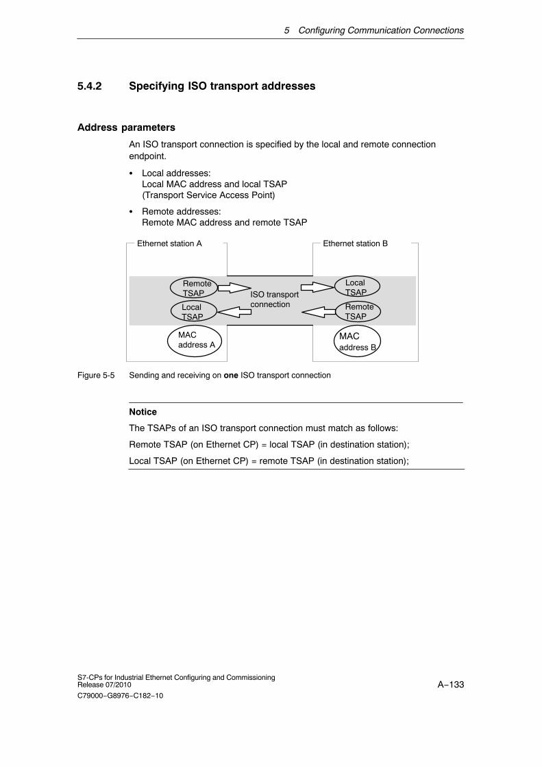
5 Configuring Communication Connections
A−133S7-CPs for Industrial Ethernet Configuring and CommissioningRelease 07/2010
C79000−G8976−C182−10
5.4.2 Specifying ISO transport addresses
Address parameters
An ISO transport connection is specified by the local and remote connectionendpoint.
� Local addresses:Local MAC address and local TSAP (Transport Service Access Point)
� Remote addresses:Remote MAC address and remote TSAP
ISO transport connection
MACaddress A
Ethernet station BEthernet station A
MACaddress B
RemoteTSAP
LocalTSAP
LocalTSAP
RemoteTSAP
Figure 5-5 Sending and receiving on one ISO transport connection
Notice
The TSAPs of an ISO transport connection must match as follows:
Remote TSAP (on Ethernet CP) = local TSAP (in destination station);
Local TSAP (on Ethernet CP) = remote TSAP (in destination station);
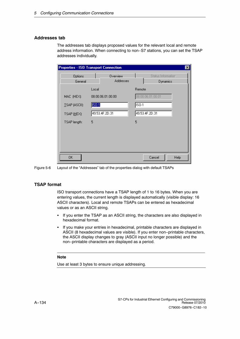
5 Configuring Communication Connections
A−134S7-CPs for Industrial Ethernet Configuring and Commissioning
Release 07/2010
C79000−G8976−C182−10
Addresses tab
The addresses tab displays proposed values for the relevant local and remoteaddress information. When connecting to non−S7 stations, you can set the TSAPaddresses individually.
Figure 5-6 Layout of the “Addresses” tab of the properties dialog with default TSAPs
TSAP format
ISO transport connections have a TSAP length of 1 to 16 bytes. When you areentering values, the current length is displayed automatically (visible display: 16ASCII characters). Local and remote TSAPs can be entered as hexadecimalvalues or as an ASCII string.
� If you enter the TSAP as an ASCII string, the characters are also displayed inhexadecimal format.
� If you make your entries in hexadecimal, printable characters are displayed inASCII (8 hexadecimal values are visible). If you enter non−printable characters,the ASCII display changes to gray (ASCII input no longer possible) and thenon−printable characters are displayed as a period.
Note
Use at least 3 bytes to ensure unique addressing.

5 Configuring Communication Connections
A−135S7-CPs for Industrial Ethernet Configuring and CommissioningRelease 07/2010
C79000−G8976−C182−10
Local and remote TSAPs
Remote and local TSAPs can be identical since the connection is uniquelyidentified by the different MAC addresses. If you require more than one connectionbetween two stations, the TSAPs must also be different.
Default TSAPs
During configuration of the local and remote TSAPs, defaults (can be changed) areproposed (for example, ISO−1 for the first connection between two partners) . Ifnew connections are configured between the same partners, the default values areautomatically incremented (for example ISO−2 etc.). With a new connection to anew partner, the value ISO−1 is used again.
Addresses tab − unspecified ISO transport connection
If you select the partner type as “unspecified”, depending on your task, you canenter address information about the communication partner here. The optionsavailable to you are explained in detail in Section 5.3.1.
The Addresses tab shown here illustrates the situation in which the MAC addressand the remote TSAP were not specified. If you do not make any further settings,this means that you are willing to accept a connection establishment request fromany communication partner.
Figure 5-7 Layout of the “Addresses” tab of the properties dialog for an unspecified connection

5 Configuring Communication Connections
A−136S7-CPs for Industrial Ethernet Configuring and Commissioning
Release 07/2010
C79000−G8976−C182−10
5.4.3 Specifying ISO transport dynamic properties
Dynamics tab
The relevant timers and counters of the connection are displayed in the Dynamicstab. You can normally accept these default values.
If necessary, for example with connections to non−Simatic systems, you can setthe timers and counters individually and influence the dynamic response of theconnection.
Figure 5-8 Layout of the “Dynamics” tab of the properties dialog
Attributes Description Access
Connection Establishment
Retransmission Time The retransmission time specifies the interval afterwhich an unsuccessful connection establishmentattempt can be triggered again (1−60 s, default 5 s)− if connection establishment is active− if connection establishment is passive (−> irrelevant)
Modifiable−−−−−
Data transfer
Retransmission Time This parameter specifies the interval after which anunsuccessful transmission attempt can be triggeredagain (100−30000 ms, default 1000 ms).
Modifiable
Max. Count Max. Count is the number of attempted transmissionsincluding the first (1−100, default 5).
Modifiable

5 Configuring Communication Connections
A−137S7-CPs for Industrial Ethernet Configuring and CommissioningRelease 07/2010
C79000−G8976−C182−10
Attributes AccessDescription
Inactivity Time The inactivity time specifies the interval after which theconnection is terminated if no sign of life is receivedfrom the partner (6−180 s, default 30 s).
Modifiable
Window Time The window time specifies the intervals at whichsign−of−life frames are sent. For SIMATIC NET CPs,the window time is set to 1/3 of the inactivity time (2−60s, default 10 s). Sign−of−life frames are sent so that theconnection is also checked with data frames duringperiods when there is no productive data exchange.
Display only
Notice
Window Time and Inactivity TimeThe partner responds to a sign of life frame with a frame. They are therefore sentto the partner station at the intervals of the window time. To make sure thatconnections are not terminated unnecessarily, the inactivity time should be at leastthree times as long as the window time.

5 Configuring Communication Connections
A−138S7-CPs for Industrial Ethernet Configuring and Commissioning
Release 07/2010
C79000−G8976−C182−10
5.4.4 Checking ISO transport connection properties
Overview Tab
The overview tab displays all the previously configured ISO transport connectionsand their parameters for this station (this is only for information and cannot bemodified).
For an example of this display, refer to Section 5.3.4.
Parameter Description
Local ID S7 Station: This is the connection ID of the ISO transport connection;
PC Station: Identification number for the connection.
Name Name entered for the connection endpoint.
CPU / Applications If you display all the ISO transport connections being operated in this stationin the multiprocessor mode (with PC stations: multiple applications), theCPU/application that is the endpoint of the particular connection is specifiedhere.
R/S or via CP With S7 CPs: Rack/slot of the local CP via which the connection isestablished.
With PC stations: Display of the CP over which the connection ismaintained.
Remote address
Specifies the remote MAC address of the connection on the Ethernetsubnet.
Local TSAP Transport Service Access Point for the local connection endpoint.
Partner TSAP Transport Service Access Point for the remote connection endpoint.
Mode Displays the mode configured in the ”Options” tab.
Status Indicates the current configuration of the connection. “Connections without assignment” are indicated by “No local CP/No remoteCP” in the status column and a “!” character at the end of the “Local ID” (forexample: 0002 A000!). Connections you are currently editing are also indicated by “!” at the end ofthe local ID.
You can set the column widths in the “Overview” tab individually.
Connection overview with multiple CPUs in an S7 station
If you operate more than one CPU in your S7 station, you can click the button toextend the overview to the connections on all CPUs.

5 Configuring Communication Connections
A−139S7-CPs for Industrial Ethernet Configuring and CommissioningRelease 07/2010
C79000−G8976−C182−10
5.5 Configuring ISO−on−TCP connection properties
Introduction
When you create a connection in the New dialog, you specify the connection typeand, as far as possible, the connection partner.
When necessary, you can adapt other connection partners that are set as defaultwhen you create a new connection as described below.
Opening the dialog
To call the dialog for special connection properties, follow the steps outlined below:
1. Select the required connection in the connection table.
2. Select the menu option Edit � Object Properties
Result: The “Properties ISO−on−TCP Connection” dialog appears.
Tabs
The following tabs are available for ISO−on−TCP connections:
� GeneralDisplays parameters that identify the connection.
� AddressesDisplays the local and remote address information.
� OptionsHere, you can decide whether you want to use the access type FETCH,WRITE, SEND/RECV or SPEED SEND/RECV for the connection.
� OverviewThis is an overview of all the configured ISO−on−TCP connections of theselected S7 station with their parameters and the status of the connection.
� Status InformationThis tab displays the current status information for the connection (valid at thetime the dialog is opened). This information corresponds to that displayed byNCM diagnostics.
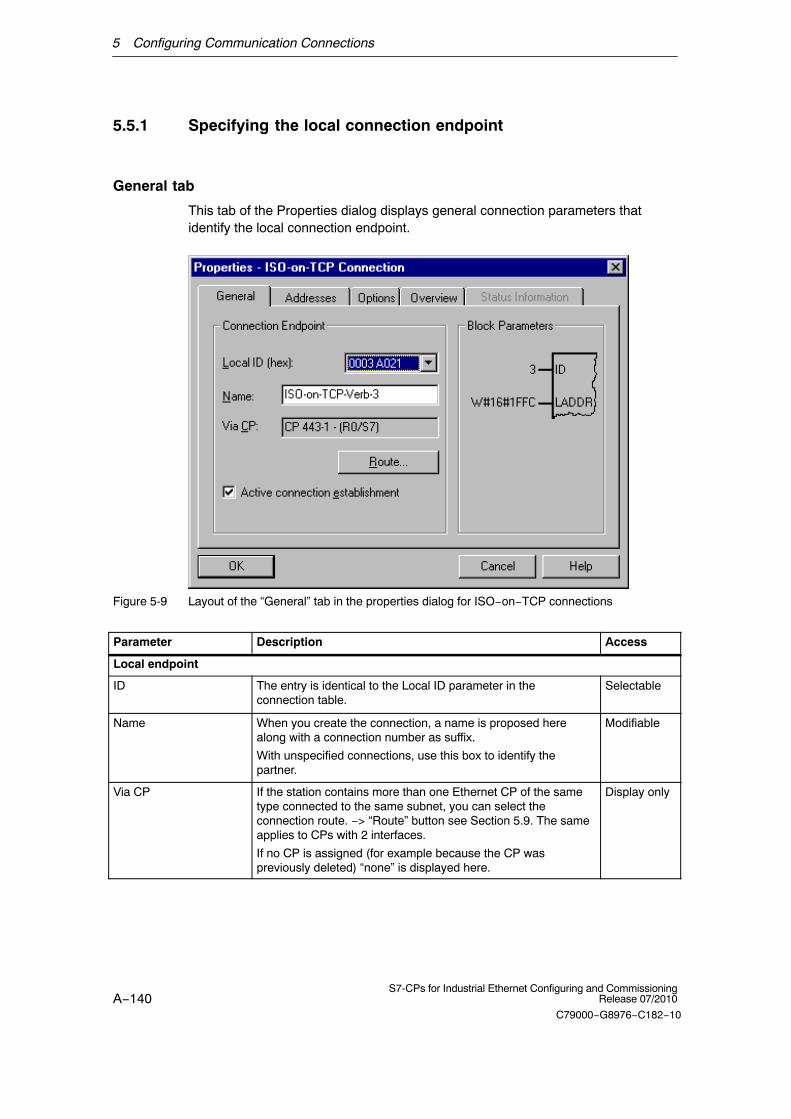
5 Configuring Communication Connections
A−140S7-CPs for Industrial Ethernet Configuring and Commissioning
Release 07/2010
C79000−G8976−C182−10
5.5.1 Specifying the local connection endpoint
General tab
This tab of the Properties dialog displays general connection parameters thatidentify the local connection endpoint.
Figure 5-9 Layout of the “General” tab in the properties dialog for ISO−on−TCP connections
Parameter Description Access
Local endpoint
ID The entry is identical to the Local ID parameter in theconnection table.
Selectable
Name When you create the connection, a name is proposed herealong with a connection number as suffix.
With unspecified connections, use this box to identify thepartner.
Modifiable
Via CP If the station contains more than one Ethernet CP of the sametype connected to the same subnet, you can select theconnection route. −> “Route” button see Section 5.9. The sameapplies to CPs with 2 interfaces.
If no CP is assigned (for example because the CP waspreviously deleted) “none” is displayed here.
Display only

5 Configuring Communication Connections
A−141S7-CPs for Industrial Ethernet Configuring and CommissioningRelease 07/2010
C79000−G8976−C182−10
Active connectionestablishment
With this option, you specify whether the connection isestablished by this S7 station. This is the default setting whenthe address of the partner is specified.
ON: the connection is established actively.
OFF: the connection is established by the partner.
If you selected partner “unspecified” when you created theconnection, the option is deselected as default. If you activatethe option, you must also specify the address of the partner inthe “Addresses” tab.
Note:
Please keep in mind the effect on the mode. If you intend to usethe FETCH or WRITE mode (see “Options” tab), the mode mustbe set to “passive” in the S7 station.
Modifiable
Block parameters
ID This value must be entered as a block call parameter ID forcalling the FC in the user program to identify the connection.The ID changes if the local ID is changed.
Display only
LADDR This value must be entered as a block call parameter ID forcalling the FC in the user program to identify the connection.
Display only
Connection name (reference) − only in multiproject
If you create a connection to a partner in another project, that has not yet beenmerged with the current multiproject, you must enter a connection name asreference. Interproject connections can then be joined up based on this reference.As soon as the connections have been brought together, the connection name(reference) can no longer be entered.

5 Configuring Communication Connections
A−142S7-CPs for Industrial Ethernet Configuring and Commissioning
Release 07/2010
C79000−G8976−C182−10
5.5.2 Specifying ISO−on−TCP addresses
Address parameters
A connection is specified by the local and remote connection endpoint.
� Local addresses:Local IP address and local TSAP (Transport Service Access Point)
� Remote addresses:Remote IP address and remote TSAP
ISO−on−TCP connection
MACaddress A
Ethernet station BEthernet station A
IP address B
RemoteTSAP
LocalTSAP
LocalTSAP
RemoteTSAP
Figure 5-10 Sending and receiving on one ISO−on−TCP connection
The address parameters are configured with NCM S7 and saved in the CPdatabase. Modifications and extensions to the Industrial Ethernet network topologydo not therefore have any effect on the CPU user program.
Notice
When you configure the Ethernet CP and the Ethernet destination station, theTSAPs of an ISO−on−TCP connection must cross match:Remote TSAP (in Ethernet CP) = local TSAP (in destination station)Local TSAP (in Ethernet CP) = remote TSAP (in destination station)
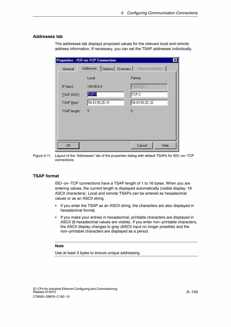
5 Configuring Communication Connections
A−143S7-CPs for Industrial Ethernet Configuring and CommissioningRelease 07/2010
C79000−G8976−C182−10
Addresses tab
The addresses tab displays proposed values for the relevant local and remoteaddress information. If necessary, you can set the TSAP addresses individually.
Figure 5-11 Layout of the “Addresses” tab of the properties dialog with default TSAPs for ISO−on−TCPconnections
TSAP format
ISO−on−TCP connections have a TSAP length of 1 to 16 bytes. When you areentering values, the current length is displayed automatically (visible display: 16ASCII characters). Local and remote TSAPs can be entered as hexadecimalvalues or as an ASCII string.
� If you enter the TSAP as an ASCII string, the characters are also displayed inhexadecimal format.
� If you make your entries in hexadecimal, printable characters are displayed inASCII (8 hexadecimal values are visible). If you enter non−printable characters,the ASCII display changes to gray (ASCII input no longer possible) and thenon−printable characters are displayed as a period.
Note
Use at least 3 bytes to ensure unique addressing.
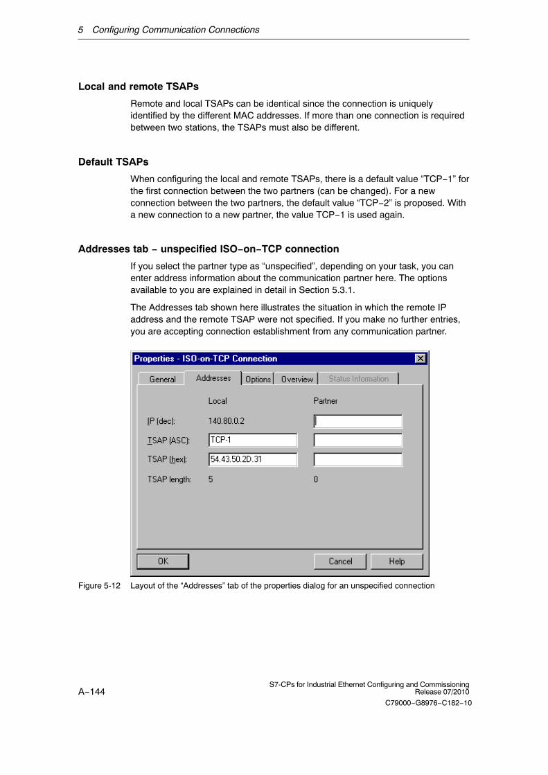
5 Configuring Communication Connections
A−144S7-CPs for Industrial Ethernet Configuring and Commissioning
Release 07/2010
C79000−G8976−C182−10
Local and remote TSAPs
Remote and local TSAPs can be identical since the connection is uniquelyidentified by the different MAC addresses. If more than one connection is requiredbetween two stations, the TSAPs must also be different.
Default TSAPs
When configuring the local and remote TSAPs, there is a default value “TCP−1” forthe first connection between the two partners (can be changed). For a newconnection between the two partners, the default value “TCP−2” is proposed. Witha new connection to a new partner, the value TCP−1 is used again.
Addresses tab − unspecified ISO−on−TCP connection
If you select the partner type as “unspecified”, depending on your task, you canenter address information about the communication partner here. The optionsavailable to you are explained in detail in Section 5.3.1.
The Addresses tab shown here illustrates the situation in which the remote IPaddress and the remote TSAP were not specified. If you make no further entries,you are accepting connection establishment from any communication partner.
Figure 5-12 Layout of the “Addresses” tab of the properties dialog for an unspecified connection

5 Configuring Communication Connections
A−145S7-CPs for Industrial Ethernet Configuring and CommissioningRelease 07/2010
C79000−G8976−C182−10
5.5.3 Checking ISO−on−TCP connection properties
Overview tab
The overview shows all the configured ISO−on−TCP connections and theirparameters (cannot be modified here). You can set the column width in the table individually.
For an example of this display, refer to Section 5.3.4 (the ISO transportconnection).
Parameter DescriptionLocal ID This is the connection ID of the ISO−on−TCP connection (STEP 7 connection
configuration; DWORD)
Name (loc.endpoint)
Entered connection name. This identifies the ISO−on−TCP connection.
CPU /Applications
If you display all the ISO transport connections being operated in this station in themultiprocessor mode (with PC stations: multiple applications), the CPU/application thatis the endpoint of the particular connection is specified here.
R/S or via CP With S7 CPs: Rack/slot of the local CP via which the connection is established.
With PC stations: Display of the CP over which the connection is maintained.
Partneraddress
Specifies the remote IP address of the connection.
Local TSAP Local Transport Service Access Point (8 characters default)
Remote TSAP Remote transport service access point (8 characters default).
Mode Displays the mode configured in the ”Options” tab.
Status Indicates the current configuration of the connection. “Connections without assignment” are indicated by “No local CP/No remote CP” in thestatus column and a “!” character at the end of the “Local ID” (for example: 0002A000!).Connections you are currently editing are also indicated by “!” at the end of the local ID.
Connection overview with multiple CPUs in an S7 station
If you operate more than one CPU in your S7 station, you can click the button toextend the overview to the connections on all CPUs.
5 Configuring Communication Connections
A−146S7-CPs for Industrial Ethernet Configuring and Commissioning
Release 07/2010
C79000−G8976−C182−10
5.6 Configuring TCP connection properties
Introduction
When you create a connection in the New dialog, you specify the connection typeand, as far as possible, the connection partner.
When necessary, you can adapt other connection partners that are set as defaultwhen you create a new connection as described below.
Opening the dialog
To call the dialog for special connection properties, follow the steps outlined below:
1. Select the required connection in the connection table.
2. Select the menu option Edit � Object Properties
Result: The “Properties − TCP Connection” dialog appears.
Tabs
The following tabs are available for TCP connections:
� GeneralDisplays parameters that identify the connection.
� AddressesDisplays the local and remote address information.
� OptionsHere, you can decide whether you want to use the access type FETCH,WRITE, SEND/RECV or SPEED SEND/RECV for the connection.
� OverviewThis is an overview of all the configured TCP connections of the selected S7station with their parameters and the status of the connection.
� Status InformationThis tab displays the current status information for the connection (valid at thetime the dialog is opened). This information corresponds to that displayed byNCM diagnostics.

5 Configuring Communication Connections
A−147S7-CPs for Industrial Ethernet Configuring and CommissioningRelease 07/2010
C79000−G8976−C182−10
5.6.1 Specifying the local connection endpoint
General tab
This tab of the Properties dialog displays general connection parameters thatidentify the local connection endpoint.
Figure 5-13 Layout of the “General” tab in the properties dialog for TCP connections
Attributes Description Access
Local endpoint
ID The entry is identical to the Local ID parameter in theconnection table.
Selectable
Name When you create the connection, a name is proposed herealong with a connection number as suffix.
With unspecified connections, use this box to identify thepartner.
Modifiable
Via CP If the station contains more than one CP of the same typeconnected to the same subnet, you can select the connectionroute. −> “Route” button see Section 5.9. The same applies toCPs with 2 interfaces.
If no CP is assigned (for example because the CP waspreviously deleted) “none” is displayed here.
Display only

5 Configuring Communication Connections
A−148S7-CPs for Industrial Ethernet Configuring and Commissioning
Release 07/2010
C79000−G8976−C182−10
Active connectionestablishment
With this option, you specify whether the connection isestablished by this S7 station. This is the default setting whenthe address of the partner is specified.
If you selected partner “unspecified” when you created theconnection, the option is deselected as default. If you activatethe option, you must also specify the address of the partner inthe “Addresses” tab.
ON: the connection is established actively.
OFF: the connection is established by the partner.
Modifiable
Use for FTP protocol Selecting this option has the following consequences:
� The TCP connection is now used as an FTP connection.
� ”Addresses” tab: The addresses are specified automatically(Port=21)
� ”Options” tab: The mode is set permanently to FTP.
� The ”Active connection establishment” option is irrelevantand cannot be set.
Configuration limits: see /1/
Precondition: The option can only be selected for anunspecified TCP connection.
Modifiable
Block parameters
ID This value must be entered as a block call parameter ID forcalling the FC in the user program to identify the connection.The ID changes if the local ID is changed.
Display only
LADDR This value must be entered as a block call parameter ID forcalling the FC in the user program to identify the connection.
Display only
Connection name (reference) − only in multiproject
If you create a connection to a partner in another project, that has not yet beenmerged with the current multiproject, you must enter a connection name asreference. Interproject connections can then be joined up based on this reference.As soon as the connections have been brought together, the connection name(reference) can no longer be entered.

5 Configuring Communication Connections
A−149S7-CPs for Industrial Ethernet Configuring and CommissioningRelease 07/2010
C79000−G8976−C182−10
5.6.2 Specifying TCP addresses
Address parameters and connection types
With TCP, the communication partners are addressed by the local and remoteendpoints as follows:
� Local addresses:Local IP address and local port
� Remote addresses:Remote IP address and remote port
TCPconnection
MACaddress A
Ethernet station BEthernet station A
IPaddress B
remoteport
localport
localport
remoteport
Figure 5-14 Sending and receiving on one TCP connection
Depending on the required connection type, the remote address parameters areeither specified or left open during configuration.
� Specified TCP connection
You specified a destination station when you created the connection.
� Unspecified TCP connection
You entered “unspecified” for the connection partner when you created theconnection.

5 Configuring Communication Connections
A−150S7-CPs for Industrial Ethernet Configuring and Commissioning
Release 07/2010
C79000−G8976−C182−10
Addresses tab − specified TCP connection
The addresses tab displays proposed values for the relevant local and remoteaddress information. You can change the port settings individually.
Figure 5-15 Layout of the properties dialog in the “Addresses” tab with DEFAULT ports for TCPconnections
Ports
The ports or port addresses define the access point to the user program within thestation/CPU. They must be unique within the station/CPU! The following tableshows the range of values:
Table 5-3
Port addresses Application / Note
0 Fixed; cannot be modified.
1 to 1023 Default assignment; should not be used(well−known ports)
1024 to 49151 Ports for application−specific protocols
2000 to 5000 Range in which a free port address is foundand assigned by the configuration tool.
You can set any port address within this range.

5 Configuring Communication Connections
A−151S7-CPs for Industrial Ethernet Configuring and CommissioningRelease 07/2010
C79000−G8976−C182−10
Table 5-3 , Fortsetzung
Port addresses Application / Note
5001 to 49151
Port addresses higher than 5000 are used bythe system!
Note:If the partner uses a port in this range for activeconnection establishment, then change the portof the partner, where possible, to a range<5000.
49152 to 65535 Dynamically assigned ports
We recommend that you do not use theseports.
The following local port numbers are reserved. You should not use these in theconnection configuration.
Table 5-4 Reserved port numbers
Port number Protocol Service
20, 21 TCP FTP
25 TCP SMTP
80 TCP HTTP
102 TCP RFC1006
135 TCP RPC−DCOM
502 TCP ASA Application Protocol

5 Configuring Communication Connections
A−152S7-CPs for Industrial Ethernet Configuring and Commissioning
Release 07/2010
C79000−G8976−C182−10
Addresses tab − unspecified TCP connection
If you select the partner type as “unspecified”, depending on your task, you canenter address information about the communication partner here. The optionsavailable to you are explained in detail in Section 5.3.1.
The Addresses tab shown here illustrates the situation in which the remote port butnot the IP address was specified. If you make no further entries, you are acceptingconnection establishment with any communication partner that uses the specifiedport.
Figure 5-16

5 Configuring Communication Connections
A−153S7-CPs for Industrial Ethernet Configuring and CommissioningRelease 07/2010
C79000−G8976−C182−10
5.6.3 Checking TCP connection properties
Overview tab
The overview shows all the previously configured TCP connections and theirparameters (cannot be modified here). You can set the column width in the table individually.
For an example of this display, refer to Section 5.3.4 (the ISO transportconnection).
Parameter Description
ID This is the connection ID of the TCP connection (STEP 7 connectionconfiguration; DWORD).
Name (loc. endpoint) Entered connection name. It identifies the TCP connection (up to 24characters).
CPU / Applications If you display all the ISO transport connections being operated in thisstation in the multiprocessor mode (with PC stations: multipleapplications), the CPU/application that is the endpoint of theparticular connection is specified here.
R/S or via CP With S7 CPs: Rack/slot of the local CP via which the connection isestablished.
With PC stations: Display of the CP over which the connection ismaintained.
Partner address Specifies the remote IP address of the connection.
Local port Local port (up to 5 digits); range of values 1 to 65353
Remote port Remote port (up to 5 digits); range of values 1 to 65353
Mode Displays the mode configured in the ”Options” tab.
Status Indicates the current configuration of the connection. “Connections without assignment” are indicated by “No local CP/Noremote CP” in the status column and a “!” character at the end of the“Local ID” (for example: 0002 A000!).Connections you are currently editing are also indicated by “!” at theend of the local ID.
Connection overview with multiple CPUs in an S7 station
If you operate more than one CPU in your S7 station, you can click the button toextend the overview to the connections on all CPUs.

5 Configuring Communication Connections
A−154S7-CPs for Industrial Ethernet Configuring and Commissioning
Release 07/2010
C79000−G8976−C182−10
5.7 Configuring UDP connection properties
Introduction
When you create a connection in the New dialog, you specify the connection typeand, as far as possible, the connection partner.
When necessary, you can adapt other connection partners that are set as defaultwhen you create a new connection as described below.
Opening the dialog
To call the dialog for special connection properties, follow the steps outlined below:
1. Select the required connection in the connection table.
2. Select the menu option Edit � Object Properties
Result The “Properties − UDP Connections“ dialog appears.
Tabs
The following tabs are available for UDP connections:
� GeneralDisplays parameters that identify the connection.
� AddressesDisplays the local and remote address information.
� OverviewOverview of all configured UDP connections of the selected S7 station withcorresponding parameters and the status of the connection.
� Status InformationThis tab displays the current status information for the connection (valid at thetime the dialog is opened). This information corresponds to that displayed byNCM diagnostics.
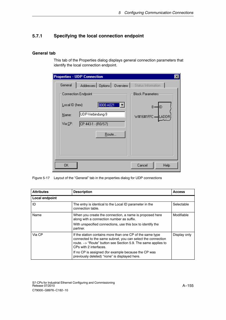
5 Configuring Communication Connections
A−155S7-CPs for Industrial Ethernet Configuring and CommissioningRelease 07/2010
C79000−G8976−C182−10
5.7.1 Specifying the local connection endpoint
General tab
This tab of the Properties dialog displays general connection parameters thatidentify the local connection endpoint.
Figure 5-17 Layout of the “General” tab in the properties dialog for UDP connections
Attributes Description Access
Local endpoint
ID The entry is identical to the Local ID parameter in theconnection table.
Selectable
Name When you create the connection, a name is proposed herealong with a connection number as suffix.
With unspecified connections, use this box to identify thepartner.
Modifiable
Via CP If the station contains more than one CP of the same typeconnected to the same subnet, you can select the connectionroute. −> “Route” button see Section 5.9. The same applies toCPs with 2 interfaces.
If no CP is assigned (for example because the CP waspreviously deleted) “none” is displayed here.
Display only

5 Configuring Communication Connections
A−156S7-CPs for Industrial Ethernet Configuring and Commissioning
Release 07/2010
C79000−G8976−C182−10
Block parameters
ID This value must be entered as a block call parameter ID forcalling the FC in the user program to identify the connection.The ID changes if the local ID is changed.
Display only
LADDR This value must be entered as a block call parameter ID forcalling the FC in the user program to identify the connection.
Display only
Connection name (reference) − only in multiproject
If you create a connection to a partner in another project, that has not yet beenmerged with the current multiproject, you must enter a connection name asreference. Interproject connections can then be joined up based on this reference.As soon as the connections have been brought together, the connection name(reference) can no longer be entered.
5.7.2 Specifying UDP addresses
Address parameters and connection types
With UDP, the communication partners are addressed using the local and remoteendpoint, as follows.
� Local addresses:Local IP address and local port
� Remote addresses:Remote IP address and remote port
Note
The term “connection” is also used here for UDP. Reason:During configuration (just as in TCP) the communication partners are assigned toeach other and therefore logically “connected”. In actual fact, with UDP there is noexplicit connection establishment between communication partners.

5 Configuring Communication Connections
A−157S7-CPs for Industrial Ethernet Configuring and CommissioningRelease 07/2010
C79000−G8976−C182−10
UDPconnection
MACaddress A
Ethernet station BEthernet station A
IPaddress B
remoteport
localport
localport
remoteport
Figure 5-18 Sending and receiving on one UDP connection
Depending on the required connection type, the remote address parameters areeither specified or left open during configuration.
� Specified UDP connection
You specified a destination station when you created the connection.
Configuring broadcast or multicast provides you with a further option (seeSection 5.7.3 below).
� Unspecified UDP connection
You entered “unspecified” for the connection partner when you created theconnection.

5 Configuring Communication Connections
A−158S7-CPs for Industrial Ethernet Configuring and Commissioning
Release 07/2010
C79000−G8976−C182−10
Addresses tab − specified UDP connections
The addresses tab displays proposed values for the relevant local and remoteaddress information. You can make the settings for the ports individually.
Figure 5-19 Layout of the properties dialog in the “Addresses” tab with DEFAULT ports for UDPconnections
Ports
The ports or port addresses define the access point to the user program within thestation/CPU. They must be unique within the station/CPU!
The following table shows the range of values:
Table 5-5
Application / Note Port addresses
Fixed; cannot be modified. 0
Default assignment; should not be used (well−known ports) 1..1024
Area used by STEP 7 in which a free port address is foundand assigned.
2000... onwards
The following local port numbers are reserved. Do not use these in the connectionconfiguration.

5 Configuring Communication Connections
A−159S7-CPs for Industrial Ethernet Configuring and CommissioningRelease 07/2010
C79000−G8976−C182−10
Table 5-6 Reserved port numbers
Protocol Port number Service
UDP 161 SNMP_REQUEST
UDP 34964 PN IO
UDP 65532 NTP
UDP 65533 NTP
UDP 65534 NTP
UDP 65535 NTP
Addresses tab − unspecified UDP connection
An unspecified UDP connection can be used in two ways:
� Free UDP connection
To configure a free UDP connection, select the “Address assignment in block”check box. The input boxes for the remote IP address and the remote port arethen deactivated since the destination addresses are now specified by the userprogram.
� Connection to a remote station in a different project
You can specify the remote IP address and the port for any destination station.The destination station can be in the current STEP 7 project or in anotherproject.
Figure 5-20 Layout of the properties dialog in the “Addresses” tab for the “free UDP connection” mode

5 Configuring Communication Connections
A−160S7-CPs for Industrial Ethernet Configuring and Commissioning
Release 07/2010
C79000−G8976−C182−10
5.7.3 UDP with broadcast and multicast
Application
With UDP, the frames are received without acknowledgment because the UDPprotocol has no provision for acknowledgments. This is intentional so that a higherspeed at low network load is achieved. This has advantages particularly whenusing multicast. If, for example, frames are sent to 100 partners, 100acknowledgments (1 per partner) would arrive at the same time at the sender.
When you select the connection partner, you have the following two extra optionson UDP connections:
� Connection to all broadcast nodes
If you select the “all broadcast nodes”, you specify that UDP frames are sent toall obtainable broadcast nodes.
Notice
When using broadcast, you can only send with S7 CPs; reception is not possible(see below)!
� Connection to all nulticast nodes
If you select “all multicast nodes” as the partner, you specify that UDP framesare sent to all nodes of a multicast group and that multicast frames can bereceived.
Multicast is a special, configurable connection option that is supported byIndustrial Ethernet CPs only on UDP connections.
When to use multicast instead of broadcast ?
To allow the simultaneous transmission of a frame to a number of partners, theconnection option Multicast for UDP connections was introduced.
In contrast to the broadcast connection option, it is also possible to receive framessent to several nodes in the multicast circle on this connection type.
By specifying a particular group of recipients (multicast circle), load on recipientsfor which the message is not intended is prevented. Multicast therefore representsa better solution than broadcast when frames are sent to groups of partnerstations.

5 Configuring Communication Connections
A−161S7-CPs for Industrial Ethernet Configuring and CommissioningRelease 07/2010
C79000−G8976−C182−10
Why does an S7 CP prevent reception on broadcast connections?
It is often necessary for one station to send frames to a number of partner stations.It is important that the frames are sent at the same time and arrive and practicallythe same time. In such situations, the use of broadcast may well be suitable. Abroadcast message is received by all nodes in the network.
A typical application is the sending of broadcast frames to find a MAC address foran IP address (ARP request).
For this reason, a communications module must accept broadcast frames andevaluate them in its software. The major disadvantage of this is that networkperformance sinks significantly if there are too many broadcast frames becauseeach individual module needs to process all the broadcast frames to find outwhether the frames were intended for it.
To avoid these disadvantages, S7 CPs handle broadcast as follows:
� Following reception, the broadcast frames are filtered out with high priority by allEthernet CPs. This means that frames that cannot be interpreted are discardedimmediately. Only frames that can be interpreted, for example an ARP request,are passed on over the LAN controller and evaluated. This prevents a negativeinfluence on the other connections by broadcast frames.
� For the application, this means that the S7 CP cannot receive broadcast framesintended for the transfer of user data. It is, however, possible for the module tosend broadcast frames within the network.
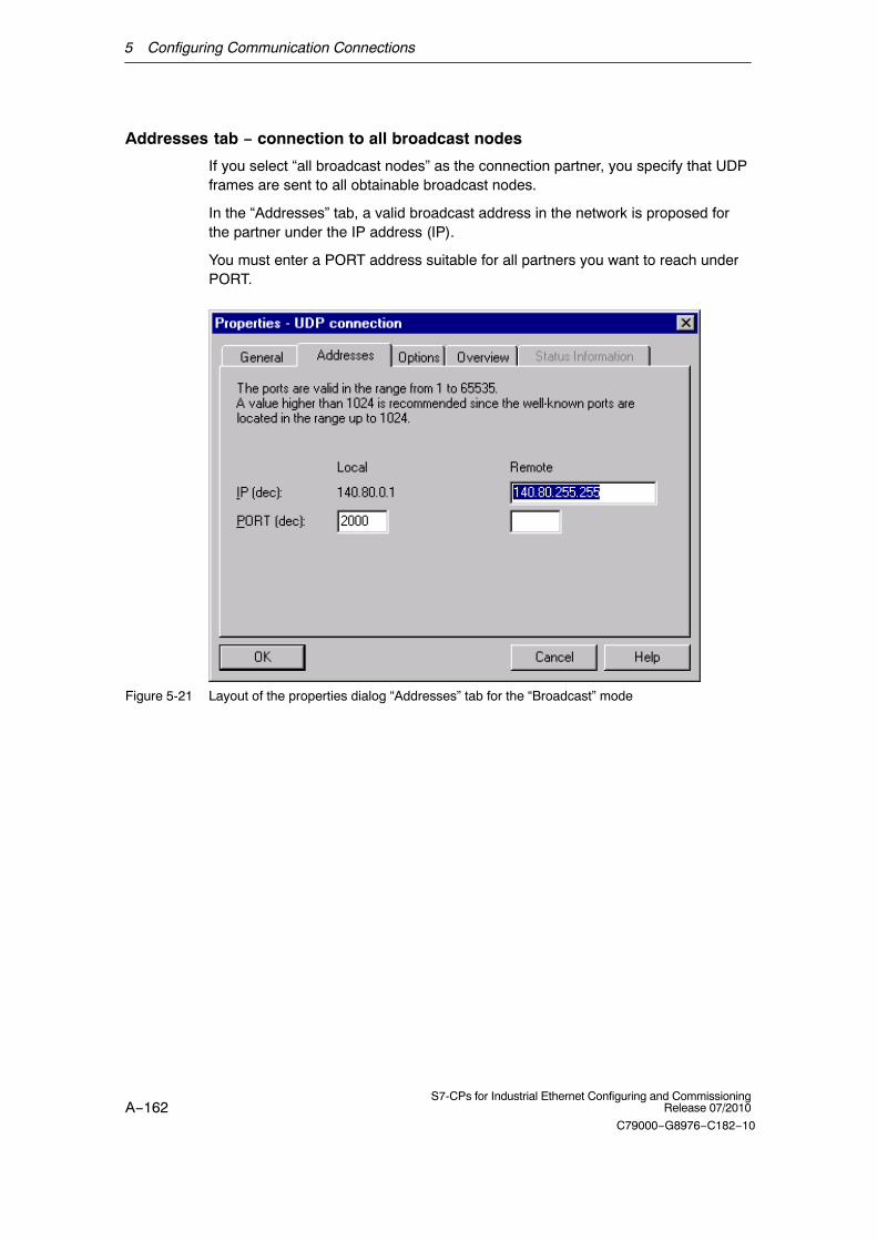
5 Configuring Communication Connections
A−162S7-CPs for Industrial Ethernet Configuring and Commissioning
Release 07/2010
C79000−G8976−C182−10
Addresses tab − connection to all broadcast nodes
If you select “all broadcast nodes” as the connection partner, you specify that UDPframes are sent to all obtainable broadcast nodes.
In the “Addresses” tab, a valid broadcast address in the network is proposed forthe partner under the IP address (IP).
You must enter a PORT address suitable for all partners you want to reach underPORT.
Figure 5-21 Layout of the properties dialog “Addresses” tab for the “Broadcast” mode

5 Configuring Communication Connections
A−163S7-CPs for Industrial Ethernet Configuring and CommissioningRelease 07/2010
C79000−G8976−C182−10
Addresses tab − Connection to all multicast nodes
By selecting “all multicast nodes” as the connection partner, you specify that
� sent UDP frames are delivered to all multicast nodes of the multicast group;
� the local device receives multicast frames in the specified multicast group.
The multicast group is specified using the IP address and the port addresses.
In the “Addresses” tab, an IP address in the network valid for multicast groups isproposed for the partner under IP address (IP). When using multicast, the partneris always a group of receivers (multicast group).
You must enter a PORT address suitable for all partners you want to reach underPORT.
In principle, is it possible to address several multicast groups with one IP address.To achieve this, you can create several UDP connections with the same IPaddress but different PORT addresses.

5 Configuring Communication Connections
A−164S7-CPs for Industrial Ethernet Configuring and Commissioning
Release 07/2010
C79000−G8976−C182−10
Notice
The port used for multicast frames must be different from the port addresses ofany UDP connections that may have been configured.
If a configured UDP connection uses the same port address, the multicast frameof another node that uses this port number may cause these connections to beterminated.(Note: Data is assigned to a configured connection based on the port number! )
Notice
Within a multicast group, you should assign identical PORT addresses for the localport and the partner port. This is the only way that frames can be sent and alsoreceived by the CP within a multicast group!
Note the following example of three nodes in the multicast group:
UDP connection
Ethernet station A
IP multicast group: 224.0.1.0PORT local 2001PORT multicast group 2001
UDP connection
Ethernet station B
IP multicast group: 224.0.1.0PORT local 2001PORT multicast group 2001
UDP connection
Ethernet station C
IP multicast group: 224.0.1.0PORT local 2001PORT multicast group 2001
Multicast group with
� IP address 224.0.1.0
� PORT address 2001
Figure 5-22 Sending and receiving in a Multicast group using identical PORT addresses

5 Configuring Communication Connections
A−165S7-CPs for Industrial Ethernet Configuring and CommissioningRelease 07/2010
C79000−G8976−C182−10
IP addresses for IP multicast
� PossibleValues
IP addresses from 224.0.0.0 to 239.255.255.255 can be used for IP multicast.
Since the IP addresses from 224.0.0.0 to 224.0.0.255 are reserved for specialpurposes, we recommend that you use IP addresses starting at 224.0.1.0(default) for IP multicast.
� Identification of the Multicast Group
On Ethernet (Internet protocol), the IP addresses of the multicast group areconverted to MAC addresses by a special mechanism.
A multicast group is not identified using the entire IP address; the first addressbyte and the most significant bit of the second address byte are ignored. This isan important feature that allows seemingly different IP addresses to addressthe same multicast group.
Example:
The following IP addresses address the same multicast group.
1000 0000
IP address Resulting multicast address
224.0.1.0
225.0.1.0
226.128.1.0
0.1.0
0.1.0
0.1.0
The resulting MAC addresses are: 01.00.5E.XX.XX.XX
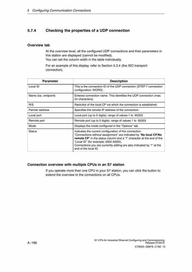
5 Configuring Communication Connections
A−166S7-CPs for Industrial Ethernet Configuring and Commissioning
Release 07/2010
C79000−G8976−C182−10
5.7.4 Checking the properties of a UDP connection
Overview tab
At the overview level, all the configured UDP connections and their parameters inthis station are displayed (cannot be modified). You can set the column width in the table individually.
For an example of this display, refer to Section 5.3.4 (the ISO transportconnection).
Parameter Description
Local ID This is the connection ID of the UDP connection (STEP 7 connectionconfiguration; WORD).
Name (loc. endpoint) Entered connection name. This identifies the UDP connection (max.24 characters).
R/S Rack/slot of the local CP via which the connection is established.
Partner address Specifies the remote IP address of the connection.
Local port Local port (up to 5 digits); range of values 1 to 65353
Remote port Remote port (up to 5 digits); range of values 1 to 65353
Mode Displays the mode configured in the ”Options” tab.
Status Indicates the current configuration of the connection. “Connections without assignment” are indicated by “No local CP/Noremote CP” in the status column and a “!” character at the end of the“Local ID” (for example: 0002 A000!).Connections you are currently editing are also indicated by “!” at theend of the local ID.
Connection overview with multiple CPUs in an S7 station
If you operate more than one CPU in your S7 station, you can click the button toextend the overview to the connections on all CPUs.

5 Configuring Communication Connections
A−167S7-CPs for Industrial Ethernet Configuring and CommissioningRelease 07/2010
C79000−G8976−C182−10
5.7.5 Free UDP connection
Program−controlled addressing
A free UDP connection allows program−controlled addressing of thecommunication partner. Communication between two nodes on Industrial Ethernethas the following properties:
� Data transfer is bi−directional; in other words it is possible to send and receiveon the UDP connection at the same time.
� The local node is specified in the configuration. The remote node is entered inthe job header of the job buffer by the user program when it calls AG_SEND.This allows any node on Ethernet/LAN/WAN to be reached.
� The IP address and the port of the sender can be read from the job header ofAG_RECV. For information on the job header, refer to “FCs for theSEND/RECEIVE interface” in /10/.
unspecifiedUDP connection
Ethernetnode(unspecified)
SIMATIC S7 station with Ethernet CP
receive
send receive
send
Job header
User data
Job header
User data
User data area
Job buffer
Figure 5-23 Sending and receiving on an unspecified UDP connection with programmed addressing
Amounts of data
Refer to the manual supplied with the Ethernet CP /1/ for the number of UDPconnections supported by the specific Ethernet CP. The number of connections perstation can be increased by adding more CPs.
Up to 2042 bytes of user data can be transferred per job buffer. The job headeruses an additional 6 bytes.

5 Configuring Communication Connections
A−168S7-CPs for Industrial Ethernet Configuring and Commissioning
Release 07/2010
C79000−G8976−C182−10
5.8 FETCH/WRITE mode
FETCH / WRITE
The FETCH/WRITE services allow direct access to the system memory areas onthe SIMATIC S7 CPU from SIMATIC S5, SIMATIC PC stations, or from devices ofother ranges.
� FETCH: Read data directly
� WRITE: Write data directly
Connection types
The FETCH/WRITE services can be configured and used in SIMATIC S7 on thefollowing connection types:
� ISO transport connections
� ISO−on−TCP connections
� TCP connections
Configuration
The mode is configured in the “Options” tab of the properties dialog of theconnection.
Depending on the station type, the following modes can be configured for theconnection endpoint:
� SIMATIC S7 station:
− SEND / RECV
− SSEND / SRECV
− FETCH PASSIVE / WRITE PASSIVE
If you select the FETCH PASSIVE or WRITE PASSIVE mode for the ISOtransport connection, you can access the system areas on a SIMATIC S7PLC from a SIMATIC S5 station or other non−S7 station (unspecifiedconnection).
The connection can be used only for this mode. Sending or receiving usingthe FCs AG_SEND/AG_LSEND/AG_SSEND orAG_RECV/AG_LRECV/AG_SRECV is then no longer possible.
The connection is established passively; in other words, only the partnerstation (SIMATIC S5 station, a PC station, or a non−SIMATIC station) canestablish the connection. The setting is made automatically in the “General”tab and cannot be changed.
5 Configuring Communication Connections
A−169S7-CPs for Industrial Ethernet Configuring and CommissioningRelease 07/2010
C79000−G8976−C182−10
Notice
Remember that with this configuration on an S7−300, one connection resource(free connection for S7 functions) of the S7−300 CPU is used. CPU connectionresources are also used, for example, by S7−300 CPs, in the FMS mode or byPGs and OPs. For more detailed information about the maximum connectionresources.
� SIMATIC PC Station: FETCH ACTIVE / WRITE ACTIVE
If you select the FETCH ACTIVE or WRITE ACTIVE mode for the ISOtransport connection, you can access the system areas on a SIMATIC S7 PLCor a SIMATIC S5 station from the PC station.
The connection establishment is active; in other words, the partner station mustwait for connection establishment (passive connection establishment on thepartner).
“S7 Addressing Mode” option
When you configure the FETCH ACTIVE / WRITE ACTIVE modes, you can selectthe addressing mode. This specifies how the addresses will be interpreted in theFETCH/WRITE call in the SIMATIC S7 station when accessing DBs:
� S7 addressing mode: byte address
� S5 addressing mode: word address
This makes it possible for applications to access S5 or S7 stations withoutadapting the addresses. This is, for example, interesting for existing S5applications that can now be used unchanged to access S7 stations.
As default, the addressing mode for access to SIMATIC S7 is set (option selected).
System memory
You can access the following address areas in the system memory on theSIMATIC S7 PLC using FETCH or WRITE:
� Data blocks (DB)
(when accessing DBs, remember that the highest DB no. is 255)
� Bit memory (M)
� Process image input table (I, IB, IW, ID)
� Process image output table (Q, QB, QW, QD)
� I/O area inputs (PIW, PID, PIB)
� I/O area outputs (PQW, PQD, PQB)
� Counters (C)
� Timers (T)

5 Configuring Communication Connections
A−170S7-CPs for Industrial Ethernet Configuring and Commissioning
Release 07/2010
C79000−G8976−C182−10
Links to other systems
The FETCH and WRITE modes supported on ISO transport connections andISO−on−TCP or TCP connections can be used with any other device to access theS7 system memory areas.
To be able to use this type of access, for example for PC applications, you need toknow the PDU structure of the jobs. The required S7 or S5 headers for requestand response frames are 16 bytes long and their structure is described in theAppendix E.
Messages in the diagnostic buffer
As a result of FETCH/WRITE access, negative acknowledgments from the S7CPU are possible. This then leads to corresponding connection−oriented entries inthe diagnostic buffer that you can read out with NCM Diagnostics.
Table 5-7 Message coding in the diagnostic buffer with FETCH/WRITE
Coding Meaning
01H Hardware error
03H Object access is not permitted.
05H Invalid address (syntax ID, area, type, bit number)
06H Data type not currently supported
07H Data type is not consistent.
0AH The object does not exist or the end of the area has beenexceeded.
FFH Internal protocol error

5 Configuring Communication Connections
A−171S7-CPs for Industrial Ethernet Configuring and CommissioningRelease 07/2010
C79000−G8976−C182−10
5.9 Routing to distribute load
Routing to distribute load
If two or more CPs of the same type exist in a station and are connected to thesame subnet, you can select the route. Clicking the ”Route” button in the ”General”tab of the properties dialog of the connection opens the ”Route” dialog:
If you have configured a load distribution on two or more Ethernet CPs at the localor remote end, you can assign the connection to the required route via the CP.
Parameter Description
Via CP / Local If more than one Ethernet CP exists in the station via which connections operated youcan select route here.
The CPs are only displayed for selection if they are networked.
If no CP is assigned (for example because the CP was deleted previously) “(None)” isdisplayed here.
If there is only one CP plugged into the station, no selection is possible.
Via CP /Partner(remote)
Depending on the local selection, the possible remote CPs are displayed. All the CPsconnected to the same subnet (networked) and the local CP can be selected.
Alternatives are available only when a connection is established to a remote stationconfigured in the same project that has two or more CPs or a CP with 2 interfaces.
If there is no CP assigned on the partner (for example because the CP was deletedpreviously) “None” is displayed here.
If there is only 1 CP (with 1 interface) in the remote station, no selection is possible.
If the partner is an “other station” or SIMATIC S5 PLC, one or more attachments aredisplayed for selection depending on the configuration and networking of the station.
�

6 CP as PROFINET IO Controller
A−172S7-CPs for Industrial Ethernet Configuring and Commissioning
Release 07/2010
C79000−G8976−C182−10
6 CP as PROFINET IO Controller
S7−300/400 station with CP in IO controller mode
The PROFINET IO controller allows direct access to PROFINET IO devices overIndustrial Ethernet.
To access the field devices connected to PROFIBUS DP, there are gatewaysavailable that are used as PROFINET IO proxies (for example theIE/PB Link PN IO).
With certain CPs for S7−300, you have the option of operating the CP additionallyor alternatively as a PROFINET IO device.
Further information on PROFINET IO
When setting up a PROFINET IO system, please read the comprehensive systemdocumentation:
� PROFINET System Description
� From PROFIBUS DP to PROFINET IOProgramming Manual, Siemens AG
This manual contains more information on the structure and function of thesupported data records.
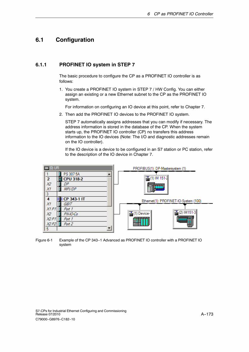
6 CP as PROFINET IO Controller
A−173S7-CPs for Industrial Ethernet Configuring and CommissioningRelease 07/2010
C79000−G8976−C182−10
6.1 Configuration
6.1.1 PROFINET IO system in STEP 7
The basic procedure to configure the CP as a PROFINET IO controller is asfollows:
1. You create a PROFINET IO system in STEP 7 / HW Config. You can eitherassign an existing or a new Ethernet subnet to the CP as the PROFINET IOsystem.
For information on configuring an IO device at this point, refer to Chapter 7.
2. Then add the PROFINET IO devices to the PROFINET IO system.
STEP 7 automatically assigns addresses that you can modify if necessary. Theaddress information is stored in the database of the CP. When the systemstarts up, the PROFINET IO controller (CP) no transfers this addressinformation to the IO devices (Note: The I/O and diagnostic addresses remainon the IO controller).
If the IO device is a device to be configured in an S7 station or PC station, referto the description of the IO device in Chapter 7.
Figure 6-1 Example of the CP 343−1 Advanced as PROFINET IO controller with a PROFINET IOsystem

6 CP as PROFINET IO Controller
A−174S7-CPs for Industrial Ethernet Configuring and Commissioning
Release 07/2010
C79000−G8976−C182−10
Notice
Keep within the IO data area limits
The module size of a PROFINET IO device must not exceed the size of the IOdata area of the PROFINET IO controller. Check the characteristic data of PROFI-NET IO in the manual of the CP. /1/
If necessary, distribute the module sizes again. When linking using a GSD file, thismust be regenerated and assigned to the IO controller
6.1.2 PROFINET IO with IRT communication
Mode of the CP in PROFINET IO with IRT communication
If you use the CP for IRT communication (Isochronous Real Time), remember thefollowing when you select the mode of the CP (S7-300 only):
You can configure the CP as IRT controller and RT device or as IRT device and RTcontroller at the same time.
It is not possible to operate the CP as IRT controller and IRT device at the sametime.
Configuring IRT
Use the following functions to configure IRT:
� Domain management
With domain management, you manage the synchronization role, the names ofthe sync domain and other characteristics.
� Topology editor
The Topology editor supports the graphic interconnection of the devicesinvolved in IRT communication. On this basis, STEP 7 calculates the optimizedflow of IRT communication.
You can use these functions HW Config by selecting the menu command Edit�PROFINET IO... �...
Follow the procedure as described in the STEP 7 basic help in the section“Configuring IRT Communication”.
For more detailed information, refer to the “PROFINET system description” /15/.

6 CP as PROFINET IO Controller
A−175S7-CPs for Industrial Ethernet Configuring and CommissioningRelease 07/2010
C79000−G8976−C182−10
Configuring the limits of the sync domain
If you use the CP for IRT communication, you will need to configure the limits ofthe sync domain for the relevant ports:
1. Open the properties dialog of the port in HW Config.
2. Open the “Options” tab and create the following configuration in the“Boundaries” box.
− End of sync domain
Select the option if you do not want the time−of−day frames forsynchronization to be forwarded to the connected communications partners;in other words, when they are located outside the sync domain.
− End of detection of accessible nodes
Select the option, if you do not want frames to be sent or received via theport to locate IRT−compliant modules in the network.
If the option is disable, information according to the DCP protocol is sent andreceived to allow discovery of the IRT−compliant modules in the network.
− End of topology discovery
Select this option if you do not want frames for discovery of theneighborhood as part of topology planning to be sent via the port.
If the option is disabled, information according to the LLDP protocol is sentto allow neighborhood discovery.
3. Close the dialog with “OK”.
6.2 IO controller mode with S7−300
6.2.1 Programming
By programming, you specify the sequence of the user program for the CPU andtherefore also access to the I/O data.
To write and read process data, use the FCs PNIO_SEND (FC11) or PNIO_RECV(FC12) from the SIMATIC NET block library in your user program.
Process data transfer with FC11 and FC12
No special FCs are necessary for PROFINET IO operation.
� PNIO_SEND (FC11), send process data
� PNIO_RECV (FC12), receive process data

6 CP as PROFINET IO Controller
A−176S7-CPs for Industrial Ethernet Configuring and Commissioning
Release 07/2010
C79000−G8976−C182−10
Optimized data transfer after failure of an IO device
The data transfer optimized by reducing the length of FC11 as described below ispossible only in the PROFINET IO controller mode.
On the PROFINET IO interface, you can optimize data transmission by calling FCPNIO_SEND (FC11) with a length (LEN parameter) shorter than the configuredtotal length of the IO data on the PNIO chain.
If you do not follow the recommendation in the manual to transfer the total lengthof the configured IO data in certain cycles, the following situation may arise:
� Following a device failure and hot restart, an IO device does not output anyprocess data.
Reason: An IO device on which only part of the output data is updated due to the optimizedtransfer, only outputs data again following a device failure after the IO controller(here the CP) has transferred the entire output data area!
6.2.2 Reading and writing data records with FB52
When the CP is acting as PROFINET IO controller, acyclic data exchange issupported by writing and reading data records with the function blockPNIO_RW_REC (FB52).
FB52 supports both functions “write data record” and “Read data record”. It can,however, only be used for data transfer in one direction at any one time, either for“read data record” or “write data record”.
6.2.3 Interrupt evaluation using FB54
Using the function block PNIO_Alarm (FB54), you can acquire, evaluate andacknowledge PROFINET IO interrupts in the user program of the controller CPU.
As long as FB54 is not called in the user program, all interrupts are acknowledgedinternally by the CP acting as PROFINET IO controller and you will not receive anyfurther information on the interrupts.
With certain interrupts, you can use FB54 to obtain additional information such asthe interrupt type or the module address. This relates to module remove/insertinterrupts or, for example, to interrupts generated on return of a station that aremapped to the IOPS or IOCS bit arrays in the FC11 and FC12 functions.
All other PROFINET IO hardware interrupts and diagnostic interrupts can also beevaluated with FB54.

6 CP as PROFINET IO Controller
A−177S7-CPs for Industrial Ethernet Configuring and CommissioningRelease 07/2010
C79000−G8976−C182−10
Note
If FB54 has been called (at least) once in the user program, it must continue to becalled to acknowledge pending interrupts. Interrupts are pending when FC12signals a value not equal to “0” in the ADD_INFO parameter.
If FB54 is no longer called after it has been called once or more in the userprogram, interrupts are not acknowledged and there is no guarantee that the IOimage will be updated correctly. The can occur, for example, following a stationreturn interrupt.
The need for continued calling of FB54 remains until the next restart on themodule.
6.3 IO controller mode with S7−400
6.3.1 Multicomputing mode − Assigning the CP to the CPU
If you use the CP in an S7 station with several CPUs (multicomputing) forPROFINET IO operation, you must assign the CP to a CPU in the configuration.
Notice
� CP slot in PROFINET IO mode
PROFINET IO operation is possible only with one CP located in the centralrack.
� CPU “startup“ configuration when using the IE/PB Link PN IO
If you use the IE/PB Link PN IO as a PROFINET IO device, select the option“Startup when expected/actual config. differ“ for the CPU in the “Startup“ tab.Otherwise your system will not start up automatically after power up orfollowing a power outage.
6.3.2 Programming
No special FBs or FCs are required for the basic functions of the PROFINET IOmode. For acyclic communication with the PROFINET IO devices using datarecords and for special additional functions, the following SFCs/SFBs are availableon the CPU:

6 CP as PROFINET IO Controller
A−178S7-CPs for Industrial Ethernet Configuring and Commissioning
Release 07/2010
C79000−G8976−C182−10
Table 6-1
Block Meaning
SFB52 “RDREC“ Read data record
SFB53 “WRREC“ Write data record
SFB54 “RALRM“ Receive interrupt
SFB81 “RD_DPAR“ Read predefined parameters
SFC70 “GEO_LOG“ Identify the start address of a module
SFC71 “LOG_GEO“ Identify the slot belonging to a logical address
For a detailed description of these blocks / functions, refer to the “System Softwarefor S7-300/400 System and Standard Functions“ manual.
Assignment of an initial value with consistent PROFINET IO user data > 32 bytes
If you have consistent PROFINET IO user data areas > 32 bytes, the system doesnot assign initial values. You should therefore set the initial value for all PROFINETIO user data areas > 32 bytes using the corresponding error OBs.
6.4 Further information on operation with PROFINET IO
6.4.1 Effects of multicast communication on RT communication
NoticeIf PROFINET IO RT communication is operated at the same time as broadcast(BC) or multicast (MC) in an Industrial Ethernet subnet, RT frames may bedelayed by long BC frames or MC frames.
These frames can, for example, be generated by the communications FCsAG_SEND or AG_RECV.
With certain constellations, this can lead to a PROFINET RT communication abort.The factors that influence this are the switch configurations (“switch depth”), theupdate time and the MC/BC frame lengths.
For more detailed information on the influencing factors and possible solutions,refer to:
http://support.automation.siemens.com/WW/view/en/29104898

7 S7−300 CP as PROFINET IO Device
A−179S7-CPs for Industrial Ethernet Configuring and CommissioningRelease 07/2010
C79000−G8976−C182−10
7 S7−300 CP as PROFINET IO Device
“Intelligent” PROFINET IO Device
The CP can be configured so that the SIMATIC 300 station can be addressed as aPROFINET IO device. Due to the programmability of SIMATIC 300 stations, theyare also known as “intelligent” PROFINET IO devices because:
Process data can be processed before it is forwarded to the PROFINET IOcontroller or after it has been received from it and output to the process I/O.
In the following sections, the name “PROFINET IO device” also refers to the CPlocated in the S7 station and configured as a PROFINET IO device.
Further information on PROFINET IO
When setting up a PROFINET IO system, please read the comprehensive systemdocumentation:
� PROFINET System Description
� From PROFIBUS DP to PROFINET IOProgramming Manual, Siemens AG
This manual contains more information on the structure and function of thesupported data records.

7 S7−300 CP as PROFINET IO Device
A−180S7-CPs for Industrial Ethernet Configuring and Commissioning
Release 07/2010
C79000−G8976−C182−10
7.1 Principle of the data exchange in IO device mode
Data exchange between controller and CP as PROFINET IO device
Data exchange between a PROFINET IO controller and PROFINET IO deviceinvolves the following procedure:
� On the PROFINET IO controller
Data exchange is initiated by the PROFINET IO controller that writes outputdata to the configured output area (O addresses) and fetches input data fromthe configured input area (I addresses).
� On the PROFINET IO device
Data is processed by the CP in the PROFINET IO device on the interface to thePROFINET IO controller.
Communication within the PROFINET IO device involves calling the FCsPNIO_RECV and PNIO_SEND in the user program of the CPU.
PROFINET IO
CPCPU
STEP 7user program
CPdatabase
PROFINETIO controller
PROFINET IO device
receive
send
PROFINET IOdata areas (DB,bit memory)
PNIO_RECV
PNIO_SEND
Processoutputs
Processinputs
Configured O addresses
Configured I addresses
Figure 7-1 Interaction between PROFINET IO Device and PROFINET IO controller
Notice
In the CPU of the IO device, the IO data areas for input data and output data aretransferred as an entire area to or from one of the data areas (DB, bit memory)including any gaps.
7 S7−300 CP as PROFINET IO Device
A−181S7-CPs for Industrial Ethernet Configuring and CommissioningRelease 07/2010
C79000−G8976−C182−10
7.2 Configuration
Configuring the CP as a PROFINET IO device involves the two following activitiesin STEP 7:
� Inserting the CP as PROFINET IO device in the IO system
The CP is assigned as a PROFINET IO device to the IO system of aPROFINET IO controller in HW Config.
� Activating the CP as a PROFINET IO device in the S7 station
The CP is inserted in a SIMATIC S7−300 station in HW Config and enabled forPROFINET IO device mode in the properties dialog.
In principle, these activities can be performed in any order. On completion of bothactivities, a coupling is established between the configured IO device and themodule configured in the S7 station.
7.2.1 Principle of the IO device coupling
The coupling between the configured IO device and the module configured in theS7 station is supported as of STEP 7 version V5.4 SP4 as an “explicit” coupling.With older STEP 7 versions, this coupling is supported only as an implicit couplingbased on the identically configured device names of the IO device and module.
”Explicit” coupling of the PROFINET IO device in the PROFINET IO system andin the station
IO device coupling means the fixed assignment of an IO device configured withSTEP 7 in a PROFINET IO system to a module that is configured in an S7 stationor in a PC station (hardware−oriented assignment).
The consistency between the device names and IP addresses in the IO device andthe module in the station can be established by the STEP 7 based on the ”explicit”coupling and can be checked during the consistency check.
Previously: ”Implicit” coupling
Modules configured as IO devices in a station with older STEP 7 versions (prior toV5.4 SP4) use implicit coupling. These modules achieved a logical assignment toan IO device configured in a PROFINET IO system by using identically configureddevice names and IP addresses.
Disadvantage: The consistency check in STEP 7 only detects that device namesand IP addresses have been assigned more than once and can output a warning.It is not possible to recognize existing couplings based on these messages.Intended couplings that should be implicit but are not established because thedevice names were entered incorrectly, cannot be detected by the consistencycheck.
7 S7−300 CP as PROFINET IO Device
A−182S7-CPs for Industrial Ethernet Configuring and Commissioning
Release 07/2010
C79000−G8976−C182−10
7.2.2 Activating the CP as a PROFINET IO device in the S7 station
The CP is enabled for PROFINET IO device mode in the properties dialog andexplicitly coupled with the IO device.
Requirement: The CP was inserted in the S7 station in HW Config.
Follow the steps below in STEP 7 / HW Config:
Notice
The IP address of the PROFINET IO device and the IP address of thePROFINET IO controller must be located in the same IP subnet.
1. Open the “PROFINET” tab in the properties dialog of the CP.
For CPs with an ERTEC interface, you will find the tab described here in theproperties dialog of the ”PN IO” interface.
2. Assign a unique name to the CP as a PROFINET node. This name may only beassigned once in the PROFINET IO line.
3. Select the option “Enable IO device mode”.
4. If you have already configured the IO device in an IO system, click the “IODevice Coupling...” button. Follow the instructions in the online help of thedisplayed dialog.
5. If you do not want to use the CP as an IRT device, close the dialog with OK.
If you do want to use the CP as an IRT device, continue first with the steps inSection 7.2.3.
6. Download the configuration data to the S7−300 station.
7.2.3 Configuring the CP as IO device with IRT communication
The following steps are only necessary if you want to use the CP as aPROFINET IO device for IRT communication. In this case, follow the steps belowin HW Config.
In the station of the IO device:
1. Double−click on the row “X2 (PN–IO)” to open the properties dialog of thePROFINET interface of the CP and open the “PROFINET” tab.
2. Disable the “Enable parallel operation as IRT controller” in the ”IO device” box.
Note: You can configure the CP as an IRT controller or as an IRT device, butnot both at the same time.
3. Close the dialog with “OK” and save the project.

7 S7−300 CP as PROFINET IO Device
A−183S7-CPs for Industrial Ethernet Configuring and CommissioningRelease 07/2010
C79000−G8976−C182−10
In the station of the IO controller:
1. Open the station window of the controller station in HW Config.
2. Open the properties dialog of the controller and create the IRT configuration inthe “Synchronization” tab.
3. Close the dialog with “OK”.
4. Open the properties dialog of a port submodule (for example “X2P1”) and setthe partners for IRT communication and the line data.
5. Close the dialog with “OK”.
6. Select an IO device in the PROFINET IO system and open the propertiesdialog of the PROFINET interface (for example, “X2 (PN–IO)”).
7. Create the IRT configuration in the “Synchronization” tab and close the dialogwith “OK”.
Repeat the last two steps for all IO devices on the PROFINET IO system thatcommunicate with the controller as sync slaves.
For details on the remaining configuration of the controller or the sync domain,refer to Section 6.1.2.
8. Save the project and download the configuration data to the S7-300 station.
Note
As soon as a CP is coupled with a PROFINET IO device, only the settings on theIO controller are relevant for the IRT configuration.
If you make synchronization settings in the properties dialog of the CP, these aresettings for its role as IO controller.

7 S7−300 CP as PROFINET IO Device
A−184S7-CPs for Industrial Ethernet Configuring and Commissioning
Release 07/2010
C79000−G8976−C182−10
7.2.4 Assigning the PROFINET IO device to a PROFINET IO system
The sections below describe the assignment of the IO device to a PROFINET IOcontroller with STEP 7.
If you do not configure your system with STEP 7, you will need to use the GSDMLfile of the CP to configure the CP in your configuration system.
http://support.automation.siemens.com/WW/view/en/19698639
PROFINET IO controller
PROFINET IO controllers can be the following:
� Stations of the type SIMATIC 300 and SIMATIC 400
− CPU with integrated PROFINET IO controller (for example CPU 317−2PN/DP).
− CPU with external PROFINET IO controller (for example CP 343−1).
� SIMATIC PC station
− For example with CP 1616
Notice
The IP address of the PROFINET IO device and the IP address of the PROFINETIO controller must be located in the same IP subnet.
Requirements for configuration in STEP 7
� A PROFINET IO controller must exist in the STEP 7 project.
� The IO system has been created:
You will see the connector symbol for the PROFINET IO system beside thePROFINET IO controller module.
Step 1: Configuring the PROFINET IO device on the IO system
1. Select the CP type you want to configure as an IO device in the hardwarecatalog folder “PROFINET IO” � “I/O” � “SIMATIC S7−CP” �.....
2. Select the device version according to the information in the device−specificpart of the manual for your CP type.
Notice
With the Advanced CP, you will also need to select a suitable version dependingon the intended mode (RT or IRT communication).
3. Connect the CP with the PROFINET IO system (drag and drop).
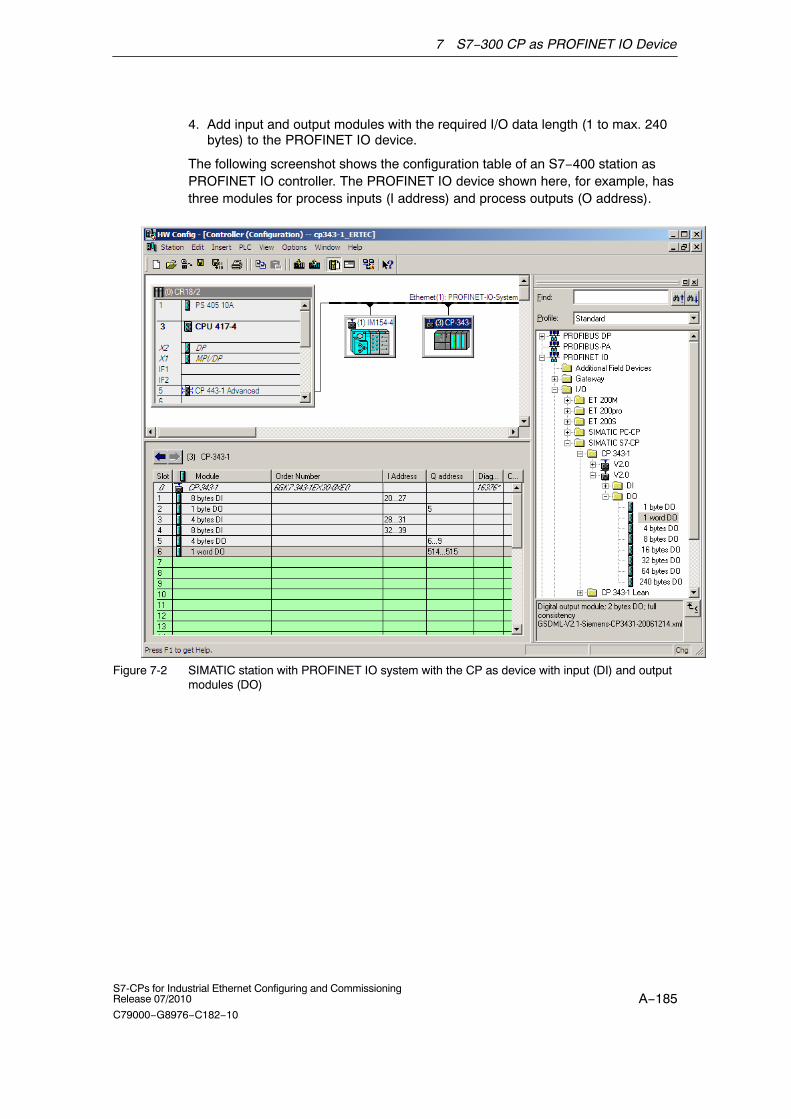
7 S7−300 CP as PROFINET IO Device
A−185S7-CPs for Industrial Ethernet Configuring and CommissioningRelease 07/2010
C79000−G8976−C182−10
4. Add input and output modules with the required I/O data length (1 to max. 240bytes) to the PROFINET IO device.
The following screenshot shows the configuration table of an S7−400 station asPROFINET IO controller. The PROFINET IO device shown here, for example, hasthree modules for process inputs (I address) and process outputs (O address).
Figure 7-2 SIMATIC station with PROFINET IO system with the CP as device with input (DI) and outputmodules (DO)

7 S7−300 CP as PROFINET IO Device
A−186S7-CPs for Industrial Ethernet Configuring and Commissioning
Release 07/2010
C79000−G8976−C182−10
Step 2: Assigning the device name to the CP as PROFINET IO device
Continue configuration in HW Config as follows:
1. Open the properties dialog of the PROFINET IO device that you inserted in thePROFINET IO system.
2. Assign the same device name in the “General” tab as you entered for thePROFINET port of the module in the S7 station (see Section 7.2.2).
3. Disable the “Assign IP address via IO Controller” option.
This step is a recommendation!
Note:
For IO device that are coupled with a module in a station in the configuration,the IP address is specified in the settings on the module.
If there is an ”explicit” coupling (as of STEP 7 V5.4 SP4), the consistency checkin STEP 7 makes sure that the configured IP addresses on the module and onthe IO device match. The ”Assign IP address via IO controller” option cantherefore be enabled or disabled without having any effect on the functionality.
In the procedure used up to now with these IO device, in which the coupling ofthe IO device with the module in the station was established based on identicaldevice names (implicit coupling), it is generally recommended that you disablethe ”Assign IP address via IO controller” option.
If the IP address configured in the S7 station is overwritten, any configuredconnections (S7, ISO−on−TCP, TCP) will no longer be established.
No further parameter assignment of the modules is necessary.
Note
By selecting suitable network components and setting the network properties,make sure that in PROFINET IO mode, the PROFINET line can be operatedwithout exception at 100 Mbps full duplex.

7 S7−300 CP as PROFINET IO Device
A−187S7-CPs for Industrial Ethernet Configuring and CommissioningRelease 07/2010
C79000−G8976−C182−10
7.3 Programming
By programming, you specify the sequence of the user program for the CPU andtherefore also access to the I/O data.
To write and read process data, use the FCs PNIO_SEND (FC11) or PNIO_RECV(FC12) from the SIMATIC NET block library in your user program.
How to use the existing functions (FCs) in your user program for PROFINET IOdevice mode is described in the following sections of this chapter.
You will find an example matching the configuration described in the previouschapter in Section 7.4.
7.3.1 Interface for programming on the PROFINET IO device
Process data transfer with FC11 and FC12
Two functions (FCs) are available for data exchange using the STEP 7 userprogram:
� PNIO_SEND (FC11)
This function reads the preprocessed process inputs of the CPU and transfersthem to the PROFINET IO controller (configured I addresses).
The preprocessed process inputs are available in a DB or bit memory area.
� PNIO_RECV (FC12)
The function accepts the data transferred by the PROFINET IO controller(configured O addresses) and writes it to the data areas of the CPU reservedfor process outputs.
Note:The transfer direction of FC11 and FC12 described here, applies only to theiruse in the PROFINET IO device. In the PROFINET IO controller, the transferdirection is the opposite (CP−CPU).
As of block version V2.0, the FC11 and FC12 can also be used if the CP functionsas PROFINET IO device and PROFINET IO controller.
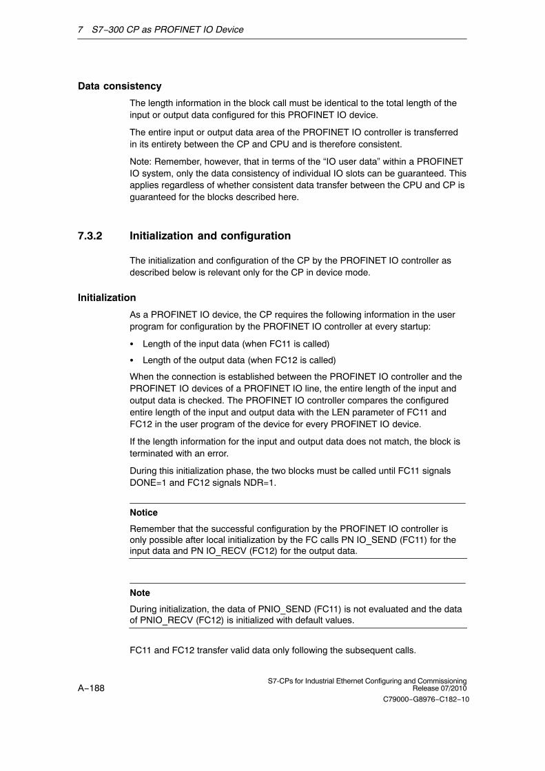
7 S7−300 CP as PROFINET IO Device
A−188S7-CPs for Industrial Ethernet Configuring and Commissioning
Release 07/2010
C79000−G8976−C182−10
Data consistency
The length information in the block call must be identical to the total length of theinput or output data configured for this PROFINET IO device.
The entire input or output data area of the PROFINET IO controller is transferredin its entirety between the CP and CPU and is therefore consistent.
Note: Remember, however, that in terms of the “IO user data” within a PROFINETIO system, only the data consistency of individual IO slots can be guaranteed. Thisapplies regardless of whether consistent data transfer between the CPU and CP isguaranteed for the blocks described here.
7.3.2 Initialization and configuration
The initialization and configuration of the CP by the PROFINET IO controller asdescribed below is relevant only for the CP in device mode.
Initialization
As a PROFINET IO device, the CP requires the following information in the userprogram for configuration by the PROFINET IO controller at every startup:
� Length of the input data (when FC11 is called)
� Length of the output data (when FC12 is called)
When the connection is established between the PROFINET IO controller and thePROFINET IO devices of a PROFINET IO line, the entire length of the input andoutput data is checked. The PROFINET IO controller compares the configuredentire length of the input and output data with the LEN parameter of FC11 andFC12 in the user program of the device for every PROFINET IO device.
If the length information for the input and output data does not match, the block isterminated with an error.
During this initialization phase, the two blocks must be called until FC11 signalsDONE=1 and FC12 signals NDR=1.
Notice
Remember that the successful configuration by the PROFINET IO controller isonly possible after local initialization by the FC calls PN IO_SEND (FC11) for theinput data and PN IO_RECV (FC12) for the output data.
Note
During initialization, the data of PNIO_SEND (FC11) is not evaluated and the dataof PNIO_RECV (FC12) is initialized with default values.
FC11 and FC12 transfer valid data only following the subsequent calls.

7 S7−300 CP as PROFINET IO Device
A−189S7-CPs for Industrial Ethernet Configuring and CommissioningRelease 07/2010
C79000−G8976−C182−10
Reasons for reinitialization
The PROFINET IO device requests reinitialization by the user program in thefollowing situations:
� The length information of the input and output areas in the FCs does not matchthe information configured for this PROFINET IO device on the PROFINET IOsystem. A change in the length in the FC calls in the user program counts as aconfiguration change.
� The CPU or CP changes to STOP mode.
� The watchdog time was exceeded (see below).
� Following a connection abort between the PROFINET IO controller andPROFINET IO device (for example because the PROFINET IO controller wasturned off).
Watchdog
FC11 and FC12 each have their own watchdog. Depending on the average CPUcycle time, the connection to the PROFINET IO controller is terminated if one ofthe two blocks is no longer called following the initialization phase.

7 S7−300 CP as PROFINET IO Device
A−190S7-CPs for Industrial Ethernet Configuring and Commissioning
Release 07/2010
C79000−G8976−C182−10
7.4 Example of configuration and programming
The configured input/output modules must be accessed in the user program of thePROFINET IO device using FCs. The FCs provide the process data preprocessedin the user program of the PROFINET IO device on the interface to the PROFINETIO controller (PNIO_SEND) or fetch the data provided by the PROFINET IOcontroller for further processing in the user program of the PROFINET IO device(PNIO_RECV).
The following example shows the configuration in HW Config and excerpts of theuser program of the CPU.
I addresses and O addresses configured on the PROFINET IO controller
The schematic shows the CP configured as a PROFINET IO device in thePROFINET IO system with three modules for process inputs and process outputs.
� Input area:
− Length: 20 bytes
− available in DB10
− transferred with FC11 PNIO_SEND
� Output area:
− Length: 7 bytes
− available in DB11
− transferred with FC12 PNIO_RECV
PNIO_SEND
PNIO_RECV
Figure 7-3 Configuring a PROFINET IO device − here, based on the example of the CP 343−1 Lean
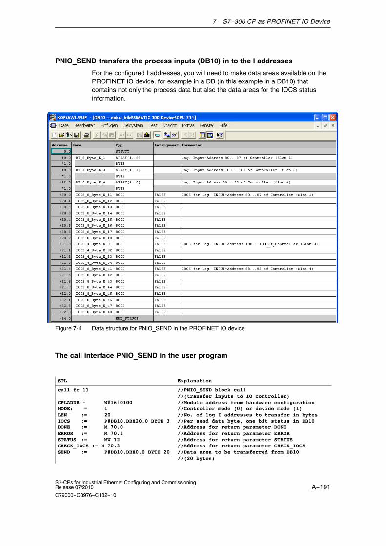
7 S7−300 CP as PROFINET IO Device
A−191S7-CPs for Industrial Ethernet Configuring and CommissioningRelease 07/2010
C79000−G8976−C182−10
PNIO_SEND transfers the process inputs (DB10) in to the I addresses
For the configured I addresses, you will need to make data areas available on thePROFINET IO device, for example in a DB (in this example in a DB10) thatcontains not only the process data but also the data areas for the IOCS statusinformation.
Figure 7-4 Data structure for PNIO_SEND in the PROFINET IO device
The call interface PNIO_SEND in the user program
STL Explanation
call fc 11
CPLADDR:= W#16#0100MODE: = 1LEN := 20IOCS := P#DB10.DBX20.0 BYTE 3DONE := M 70.0ERROR := M 70.1STATUS := MW 72CHECK_IOCS := M 70.2SEND := P#DB10.DBX0.0 BYTE 20
//PNIO_SEND block call //(transfer inputs to IO controller)//Module address from hardware configuration//Controller mode (0) or device mode (1)//No. of log I addresses to transfer in bytes//Per send data byte, one bit status in DB10//Address for return parameter DONE//Address for return parameter ERROR//Address for return parameter STATUS//Address for return parameter CHECK_IOCS//Data area to be transferred from DB10 //(20 bytes)

7 S7−300 CP as PROFINET IO Device
A−192S7-CPs for Industrial Ethernet Configuring and Commissioning
Release 07/2010
C79000−G8976−C182−10
PNIO_RECV transfers the O addresses to the process outputs (DB11)
For the configured O addresses, you will need to make data areas available on thePROFINET IO device, for example in a DB (in this example in a DB11) thatcontains not only the process data but also the data areas for the IOPS statusinformation.
Figure 7-5 Data structure for PNIO_RECV in the PROFINET IO device
The call interface PNIO_RECV in the user program
STL Explanation
call fc 12
CPLADDR:= W#16#0100MODE: = 0LEN := 7IOPS := P#DB11.DBX7.0 BYTE 1NDR := M 74.0ERROR := M 74.1STATUS := MW76CHECK_IOPS := M74.2RECV := P#DB11.DBX0.0 BYTE 7ADD_INFO:= MW 26
//PNIO_RECV block call //(read outputs from IO controller)//Module address from hardware configuration//Device mode without parallel operation//No. of log O addresses to transfer in bytes//Per receive data byte one status bit in DB11//Address for return parameter NDR//Address for return parameter ERROR//Address for return parameter STATUS//Address for return parameter CHECK_IOPS//Received data in DB11 (7 bytes)//Diagnostic information
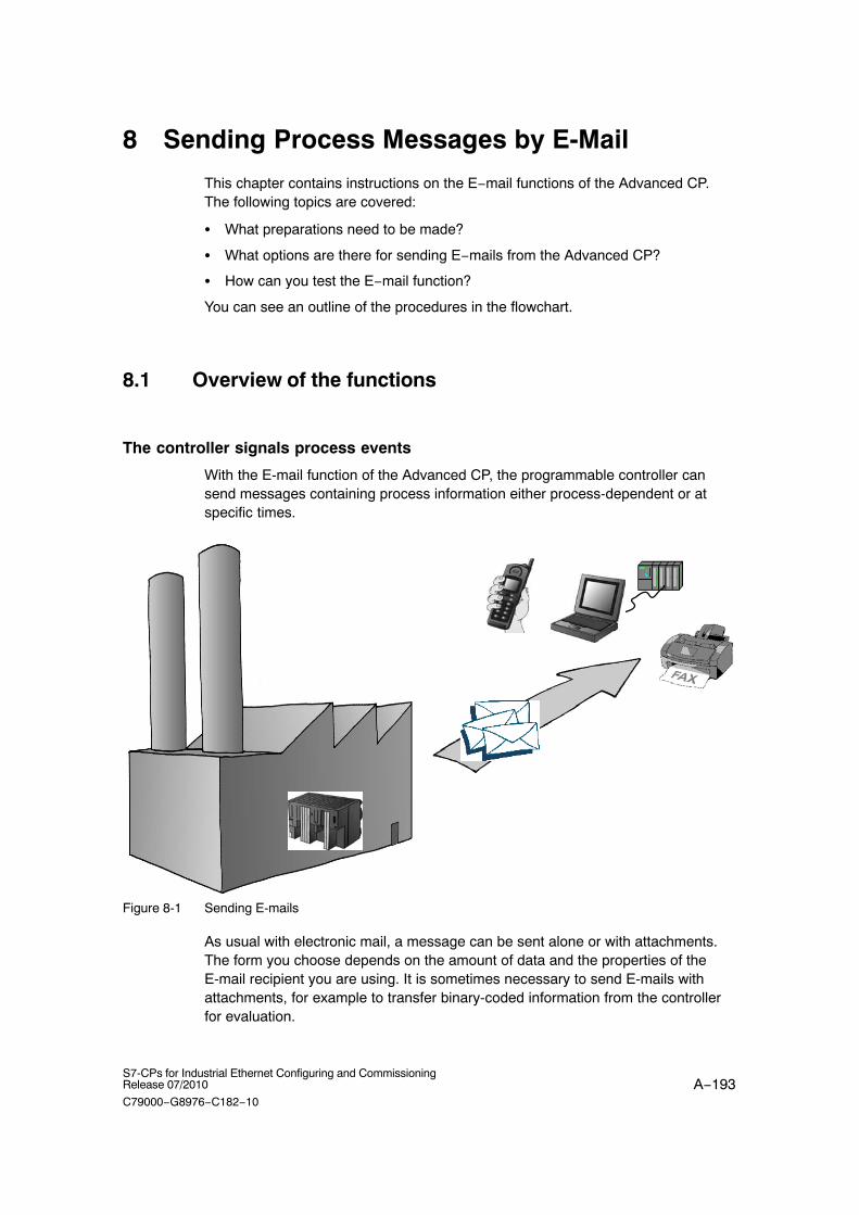
A−193S7-CPs for Industrial Ethernet Configuring and CommissioningRelease 07/2010
C79000−G8976−C182−10
8 Sending Process Messages by E-Mail
This chapter contains instructions on the E−mail functions of the Advanced CP.The following topics are covered:
� What preparations need to be made?
� What options are there for sending E−mails from the Advanced CP?
� How can you test the E−mail function?
You can see an outline of the procedures in the flowchart.
8.1 Overview of the functions
The controller signals process events
With the E-mail function of the Advanced CP, the programmable controller cansend messages containing process information either process-dependent or atspecific times.
Figure 8-1 Sending E-mails
As usual with electronic mail, a message can be sent alone or with attachments.The form you choose depends on the amount of data and the properties of theE-mail recipient you are using. It is sometimes necessary to send E-mails withattachments, for example to transfer binary-coded information from the controllerfor evaluation.

8 Sending Process Messages by E-Mail
A−194S7-CPs for Industrial Ethernet Configuring and Commissioning
Release 07/2010
C79000−G8976−C182−10
8.1.1 Authentication and other features of the Advanced CP
Features of the CP
� The Advanced CP operates as an E-mail client. It supports the SMTP service(Simple Mail Transfer Protocol).
� As of device type CP 343–1 Advanced (GX30) and CP 443–1 Advanced(GX20), ESMTP with authentication is supported.
� E-mails can be sent by the programmable controller but cannot be received.
To send E-mail in the user program of the S7 CPU, use the send call of theSEND/RECEIVE interface (FC AG_SEND / AG_LSEND).
Authentication
Advanced CPs that use ESMTP with authentication support the followingauthentication methods:
� PLAIN
� LOGIN
� CRAM−MD5
� DIGEST−MD5
For communication between CP and mail server, the following situations arepossible in terms of authentication:
� CP and mail server use authentication (same method)
Once the CP has established a connection to the mail server, the mail serversends a list of the authentication methods it supports. The CP searches throughthe received list for the supported authentication method. It searches in theorder of authentication methods as shown in the list above. The first methodfound in the list is then used. The CP informs the mail server of the method.
You have to enter the data required for authentication (user name andpassword) in the E−mail data block (see Section 8.4.1). The user name andpassword correspond to the login data of the mail service provider.
There is no authentication if the user name and password are not specified inthe DB.
� CP and mail server use authentication (different methods)
If the CP does not find a suitable authentication method, it aborts thetransmission and generates a diagnostic message (see Section 12.7).
� The CP uses authentication, the mail server does not
If you use a CP that supports authentication but you want to work withoutauthentication, do not enter a user name and password in the E−Mail data block(see Section 8.4.1). In this case, the CP transfers the data using SMTP.
� The mail server uses authentication, the CP does not
The mail server aborts sending.

8 Sending Process Messages by E-Mail
A−195S7-CPs for Industrial Ethernet Configuring and CommissioningRelease 07/2010
C79000−G8976−C182−10
8.2 Configuration
8.2.1 Procedure
Follow the steps below to send E−mails:
Configure the E-mail connection
See Section 8.3
Clarify mail server mode:
� Is there already a mail server in your network environment?
� Who can set up access for the CP?
Send E-mails from the user program
See Section 8.4
Receive E−mail on receiving device
Check availability: Start/send a test mail
See Section 8.5
with Webbrowser or NCM Diagnostics
Use FCAG_SEND/AG_LSEND
with STEP 7 /NetPro
� Configure the E-mail connection
By configuring an E-mail connection you allow establishment of a connectionbetween the S7 CPU and the Advanced CP for sending E-mails.
� Check availability
You can check the availability of the E-mail function at any time by initiating atest mail on the Advanced CP. For more detailed information, refer to Section8.5.

8 Sending Process Messages by E-Mail
A−196S7-CPs for Industrial Ethernet Configuring and Commissioning
Release 07/2010
C79000−G8976−C182−10
� Send E-mails from the user program
The information to be sent by E-mail including the address information is storedin a data block (DB). The information is sent via the user program using an FCAG_SEND/AG_LSEND.
8.2.2 Options of mail server mode
In principle there are three ways of operating the required mail server. Thefollowing table explains the advantages and special features:
Table 8-1
Mail server mode Advantage Special Features necessary steps
Internal/local
You use the mail serversoftware on a PCavailable in your LAN.
� Fast installation
� Cost−effective
� E-mail receptiononly within thecompany
� Use of mail serversoftware
Internal with externalconnection
You use a mail serverset up in your intranetthat can pass on mails tothe outside.
� Use of an existinginfrastructure
� Output to externaldevices such asmobile phones, faxpossible 1)
� Administrative tasksinvolved
External
You address a mailserver outside yourintranet.
� Inexpensive if you donot have your owninfrastructure
� Output to externaldevices such asmobile phones, faxpossible 1)
� Registration withprovider
� Making a routeravailable
1) Sending E−mails to mobile phones or to fax devices is possible using “SMS/Fax Gateway”. How to addressthe gateway and to enable the recipient depends on the particular service provider.
8.2.3 Configuring a mail server and addressing recipients
Addressing the recipient takes two stages:
� Configured mail server address
You specify the address of the mail server during configuration of theconnection. For this configuration, you must know the IP address (absolute orsymbolic) of the mail server.

8 Sending Process Messages by E-Mail
A−197S7-CPs for Industrial Ethernet Configuring and CommissioningRelease 07/2010
C79000−G8976−C182−10
In the following schematic, one possibility, namely that of a mail serverconnected to your intranet is assumed (see Table 8-1; Mail server operation“internal with external connection”).
Example: server.local
� Programmed recipient address
You specify the recipient address in the data block in the user program in whichthe E-mail is prepared.
Example: [email protected]
STEP 7 configuration
plant.control
User program
Mail server: server.local
server.local
provider.com
E-mail DB with the recipient address:
Figure 8-2
Make sure that the relevant ports of the communication partner of the CP areopened.
8.3 Setting up an E−mail connection
Overview
To send E-mails, one E-mail connection must always be set up per Advanced CP.The E-mail connection specifies the mail server via which all the mails sent by theAdvanced CP are delivered.

8 Sending Process Messages by E-Mail
A−198S7-CPs for Industrial Ethernet Configuring and Commissioning
Release 07/2010
C79000−G8976−C182−10
You can set up an E−mail connection as follows:
� During connection configuration in STEP 7 (standard application)
This situation is described below.
� In the user program with FB CP_CONFIG and the configuration data block.
There are situations in which it is an advantage to set up the communicationconnections not over the configuration interface of STEP 7 but ratherprogram−controlled by specific applications.
This use case is described in detail in /10/.
Requirements
You can set up an E-mail connection after the Advanced CP has been configuredin the station with STEP 7 HW Config.
How to configure an E−mail connection
Follow the steps below to configure an E−mail connection in STEP 7 / NetPro:
1. Select the connection type E-mail in the “New Connection” dialog. As theconnection partner, select “(Unspecified)” or “Other station”.
2. Select the Option “Open Properties Dialog” and confirm your entry.
3. Select the Addresses tab in the Properties dialog and specify the addressparameters.
Figure 8-3

8 Sending Process Messages by E-Mail
A−199S7-CPs for Industrial Ethernet Configuring and CommissioningRelease 07/2010
C79000−G8976−C182−10
Table 8-2 Available parameters
Parameter Description Examples
E-mail Server − IPAddress
Address of the mail server, over which the E-mailsare sent.
You can specify an absolute or alias IP address.
The use of an alias assumes that the Advanced CPknows the address of the domain name server(DNS). This entry must be made when configuringthe Advanced CP in HW Config; For more detailedinformation refer to the STEP 7 online help.
� absolute:
140.80.0.4
� As an alias:
mail.compuserve.com
Default sender address Specifies an address that is always inserted in theE−mail as the sender address if the senderinformation (FROM parameter) is empty in theheader of the E−mail (DB, refer to Section 8.4).
A maximum of 126 characters can be specified.
4. Confirm your entry and close the dialog. After downloading the configurationdata, the user program can send E-mails on this E-mail connection.
8.4 Sending an E−mail
Overview
To send an E-mail:
� Prepare the E-mail data in a data block.
� Use the function ( FC) AG_SEND or AG_LSEND in the user program.
Requirement
You can send E-mails if the E-mail connection was set up in the connectionconfiguration with STEP 7. You use the ID specified in the connectionconfiguration for the FC AG_SEND/AG_LSEND call.
8.4.1 E−mail data block
The entire E-mail, in other words, the address information and the message itself,is put together in a data block. Below, you will find an example of the DB structurerequired based on an example in STL notation.
Use the LAD/FBD/STL editor for creating and entering the DB data.

8 Sending Process Messages by E-Mail
A−200S7-CPs for Industrial Ethernet Configuring and Commissioning
Release 07/2010
C79000−G8976−C182−10
Table 8-3 E-mail data block in STL notation in STEP 7
Address Name Type Initial value Comment Entry
0.0 STRUCT
+0.0 USER1)
STRING[40] ’USER:[email protected];’ User name
+42.0 PASS 1) STRING[40] ’PASS:password;’ Password
+84.0 TO 2) STRING[40] ’TO:[email protected];’ Recipient mandatory
+126.0 CC 2) STRING[40] ’CC:[email protected];’ CC recipient optional
+168.0 FROM STRING[40] ’FROM:[email protected];’
Sender optional
+210.0 SUB STRING[40] ’SUB:Status Station 7;’ Topic optional
+252.0 Text STRING[100] ’TXT:Fault in plant Sector 2’ Mail text mandatory
+354.0 File 3) STRING[40] ’FILE:filename.txt;’ File name of theattachment
optional
+396.0 Attachment
STRING[4] ’BNY:’ The attachment isintroduced here5)
optional
+402.0 Value1 BYTE B#16#27 4) Attachment/binaryvalue 5)
optional
+403.0 Value2 BYTE B#16#03 4) Attachment/binaryvalue 5)
optional
=404.0 END_STRUCT
1) A username and password are only necessary if authentication is required. The order is irrelevant.
2) Several recipients can be specified. In this case, separate recipients by a comma.
3) If no file name is specified for the attachment, the CP uses the name ”DATA.BIN”.
4) The information is sent to the recipient as an attachment.
5) Data can also be supplied dynamically.
Notes on Table 8-3:
� Structure and syntax of the data in the E−mail DB
The structure suggested here with several STRINGs is one of severalvariations. The entries in the “Initial value” column with the IDs (TO:, SUB:, CC:,FROM:, TXT:, BNY:) are decisive. These must be used with exactly this syntaxin the DB to identify the mail contents! All the entries must be completed with asemicolon; no semicolon is permitted after the last entry.
The string length indicated in the table is only an example; it can be adapted tothe actual number of characters (exception: the string length for the plantidentifier must be specified as [4]).
Another variation, could be, for example, to use only one STRING and to assignthe entire text with the IDs.
� If you have problems entering the @ character, use ALT 64.
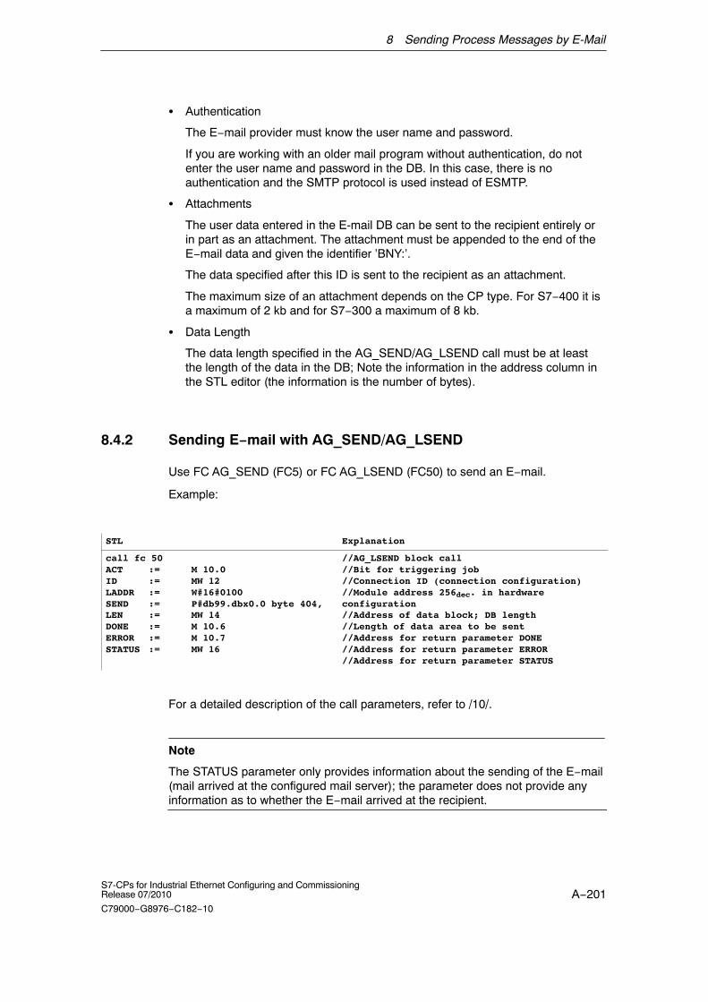
8 Sending Process Messages by E-Mail
A−201S7-CPs for Industrial Ethernet Configuring and CommissioningRelease 07/2010
C79000−G8976−C182−10
� Authentication
The E−mail provider must know the user name and password.
If you are working with an older mail program without authentication, do notenter the user name and password in the DB. In this case, there is noauthentication and the SMTP protocol is used instead of ESMTP.
� Attachments
The user data entered in the E-mail DB can be sent to the recipient entirely orin part as an attachment. The attachment must be appended to the end of theE−mail data and given the identifier ’BNY:’.
The data specified after this ID is sent to the recipient as an attachment.
The maximum size of an attachment depends on the CP type. For S7−400 it isa maximum of 2 kb and for S7−300 a maximum of 8 kb.
� Data Length
The data length specified in the AG_SEND/AG_LSEND call must be at leastthe length of the data in the DB; Note the information in the address column inthe STL editor (the information is the number of bytes).
8.4.2 Sending E−mail with AG_SEND/AG_LSEND
Use FC AG_SEND (FC5) or FC AG_LSEND (FC50) to send an E−mail.
Example:
STL Explanation
call fc 50ACT := M 10.0ID := MW 12LADDR := W#16#0100SEND := P#db99.dbx0.0 byte 404,LEN := MW 14DONE := M 10.6ERROR := M 10.7STATUS := MW 16
//AG_LSEND block call//Bit for triggering job//Connection ID (connection configuration)//Module address 256dec. in hardwareconfiguration//Address of data block; DB length//Length of data area to be sent//Address for return parameter DONE//Address for return parameter ERROR//Address for return parameter STATUS
For a detailed description of the call parameters, refer to /10/.
Note
The STATUS parameter only provides information about the sending of the E−mail(mail arrived at the configured mail server); the parameter does not provide anyinformation as to whether the E−mail arrived at the recipient.

8 Sending Process Messages by E-Mail
A−202S7-CPs for Industrial Ethernet Configuring and Commissioning
Release 07/2010
C79000−G8976−C182−10
8.5 Testing the E-mail function
Purpose and possibilities
With E-mail functionality, you make your programmable controller capable ofsending specific up-to-date information from the process at any time.
To allow you to check that E-mail is functioning correctly at any time, you caninitiate a test mail. The following mechanisms are available for the test mail:
� Test mail via Web browser
� Test mail using NCM Diagnostics (only without authentication)
Both tests are triggered on the CP which means that the tests do not indicatewhether or not there is an E−mail connection between the CPU and CP. If this wasconfigured incorrectly, it is not possible to send E−mails from the user program.
Conclusions drawn from receiving a test mail
If the test mail is received, you can conclude the following:
� The Advanced CP is ready to send E-mails
� An E-mail connection is established that can be used by the user program.
� The recipient specified in the request is available.
You cannot draw conclusions about the following:
� The status of the user programs in which the sending of E-mails is started bycalling FC AG_SEND/AG_LSEND
� The time required from a mail being sent until it is received.
Note:
E−mail is an unreliable service. It is therefore possible that an E−mail does notarrive. The reception of a test E−mail is only a temporary indication that theconnection is working and is no guarantee that it will work at other times.
Triggering a test mail with the Web browser
Web diagnostics (see Section 11.3.7) allows you to send a test mail from your CP.
Requesting a test mail using NCM diagnostics
In the “E-mail” tab of NCM diagnostics, you can also specify and trigger a test mail.To do this, you require an online connection between you PC/PG and your S7station.
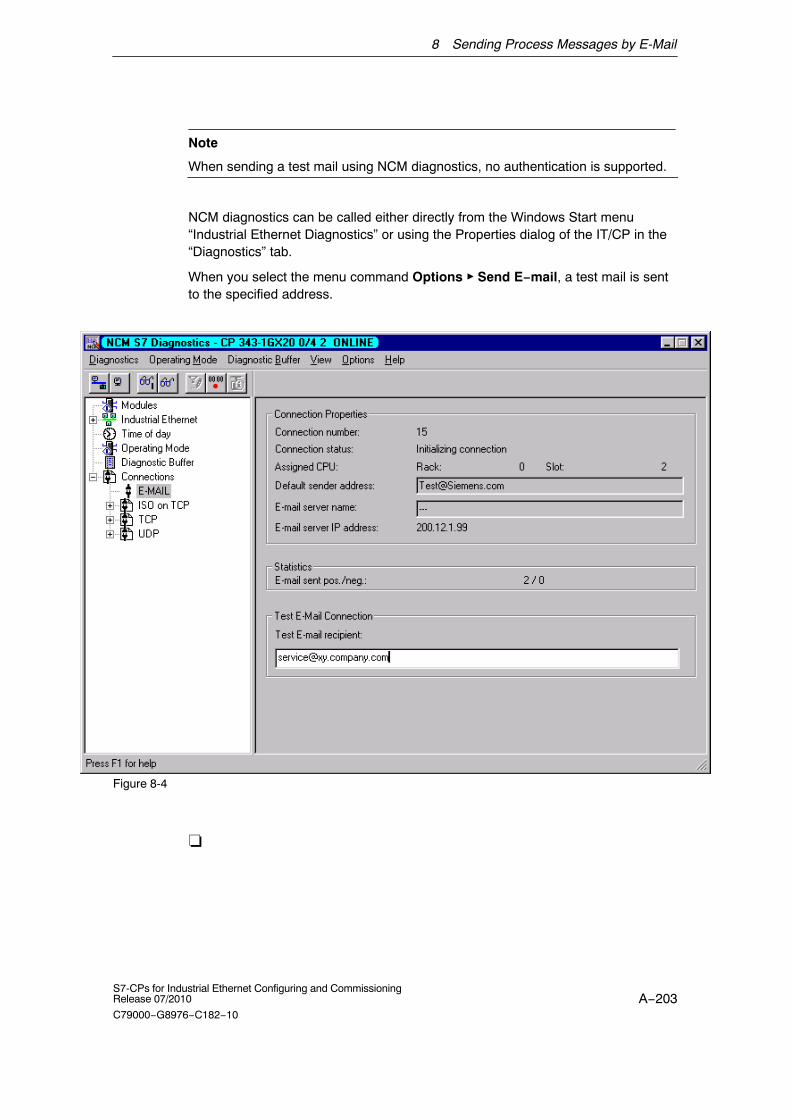
8 Sending Process Messages by E-Mail
A−203S7-CPs for Industrial Ethernet Configuring and CommissioningRelease 07/2010
C79000−G8976−C182−10
Note
When sending a test mail using NCM diagnostics, no authentication is supported.
NCM diagnostics can be called either directly from the Windows Start menu“Industrial Ethernet Diagnostics” or using the Properties dialog of the IT/CP in the“Diagnostics” tab.
When you select the menu command Options � Send E−mail, a test mail is sentto the specified address.
Figure 8-4
�

A−204S7-CPs for Industrial Ethernet Configuring and Commissioning
Release 07/2010
C79000−G8976−C182−10
9 File Management and File Access with FTP
With its file transfer functions (FTP), the Advanced CP provides a useful tool fortransferring files to and from your S7 station.
Files can be transferred both from the PG/PC to the S7 station or initiated by theS7 station to an FTP server; this could be, for example, a PC/PG station oranother S7 station.
This chapter will familiarize you with the FTP client and FTP server functionality ofthe Advanced CP in the S7 station.
For a detailed description of the functions (FCs) or of FB40 that you require for filetransfer from your S7 station, refer to /10/.
Note
We recommend that you always use the latest block versions for all module types.
You will find information on the current block versions and the current blocks todownload from the Internet in our customer support.
http://support.automation.siemens.com/WW/view/en/8797900
This recommendation assumes that you are using the latest firmware for thismodule type.
Notice
In FTP server mode, make sure that the relevant ports of the CP and thecommunication partner of the CP are opened. For more details on this topic andon configured access rights and security aspects, refer to Section 10.2.

9 File Management and File Access with FTP
A−205S7-CPs for Industrial Ethernet Configuring and CommissioningRelease 07/2010
C79000−G8976−C182−10
9.1 FTP functions in an S7 station with the Advanced CP
Range of functions
The FTP functions of the Advanced CP support both FTP client and FTP serverfunctionality on the S7 station.
S7 station with an Advanced CP in the role of FTP server
The server role can be divided into two distinct functions:
� The Advanced CP as FTP server for the file system on the Advanced CP
You can access the files of the file system on the Advanced CP (CP 443−1 IT /CP 343−1 IT) from an FTP client, for example a PG/PC. These files are madeup mainly of the HTML pages intended for display in the Web browser.
FTP client FTP server
File systemS7 − 400PG/PC S7 − 300
� The Advanced CP as FTP server for CPU data
When working on FTP client, for example a PG/PC, you can access the datablocks on the CPU of the S7 stations via the Advanced CP.
FTP client FTP server
S7 − 400PG/PCCPU data blocks S7 − 300
S7 station with Advanced CP in the FTP client role for CPU data
The user program on the CPU can access the Advanced CP as an FTP client forthe transfer of data blocks from or to an FTP server.
FTP client FTP server
S7 − 400CPU data blocksS7 − 300

9 File Management and File Access with FTP
A−206S7-CPs for Industrial Ethernet Configuring and Commissioning
Release 07/2010
C79000−G8976−C182−10
9.2 Advanced CP as FTP server for the file system on the CP
9.2.1 Method
The Advanced CP manages the predefined HTML system pages as well as theHTML pages you have created yourself in a special memory area.
With FTP, you have standardized accents to the files managed on the AdvancedCP.
FTP server: S7 station withAdvanced CP
FTP client: PG/PC
S7 − 300S7 − 400
The following screenshot is an example of a typical access sequence in theMS−DOS window:
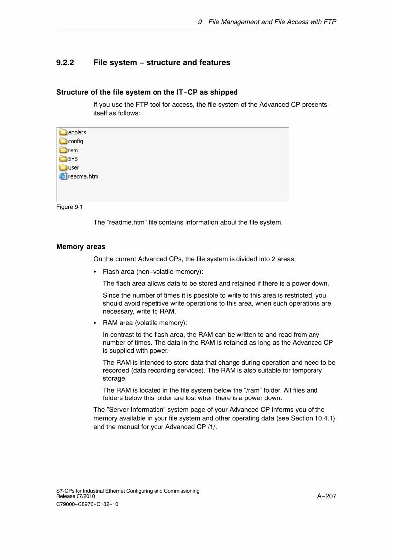
9 File Management and File Access with FTP
A−207S7-CPs for Industrial Ethernet Configuring and CommissioningRelease 07/2010
C79000−G8976−C182−10
9.2.2 File system − structure and features
Structure of the file system on the IT−CP as shipped
If you use the FTP tool for access, the file system of the Advanced CP presentsitself as follows:
Figure 9-1
The “readme.htm” file contains information about the file system.
Memory areas
On the current Advanced CPs, the file system is divided into 2 areas:
� Flash area (non−volatile memory):
The flash area allows data to be stored and retained if there is a power down.
Since the number of times it is possible to write to this area is restricted, youshould avoid repetitive write operations to this area, when such operations arenecessary, write to RAM.
� RAM area (volatile memory):
In contrast to the flash area, the RAM can be written to and read from anynumber of times. The data in the RAM is retained as long as the Advanced CPis supplied with power.
The RAM is intended to store data that change during operation and need to berecorded (data recording services). The RAM is also suitable for temporarystorage.
The RAM is located in the file system below the “/ram“ folder. All files andfolders below this folder are lost when there is a power down.
The ”Server Information” system page of your Advanced CP informs you of thememory available in your file system and other operating data (see Section 10.4.1)and the manual for your Advanced CP /1/.

9 File Management and File Access with FTP
A−208S7-CPs for Industrial Ethernet Configuring and Commissioning
Release 07/2010
C79000−G8976−C182−10
Available storage
For information on the total memory available in the file system, the currentlyavailable memory in the flash area and in the RAM area of the file system andother operational data, refer to the Web diagnostics of your Advanced CP (startpage/file system) and the manual of your Advanced CP /1/.
Files are protected by access rights
Chapter 10.2 explains the security mechanisms governing information exchangeusing a Web browser. Section 3.4.9 explains how access rights are created whenyou configure the Advanced CP.
The Advanced CP reacts to file access using FTP according to the access rights;in other words you must authorize the access using a password. The specifieduser must also have the right to access files on the S7 station with FTP (seeSection 3.4.9 ).
Notice
Remember that using the “everybody” user name, access is possible without apassword, however this user name normally has no access rights.
File access with FTP tools
Depending on your requirements, you can use different methods and tools for FTPaccess.
� Special FTP tools
Special FTP tools are available that allow convenient use of FTP commands.Generally, working with these tools is very similar to working with the WindowsExplorer. This means that you will use functions such as copying, moving ordeleting files intuitively rather than having to worry about the syntax of FTPcommands. You will only need the MS DOS prompt occasionally.
Notice
Please note that with several CP types the file names in the file system describedhere are case−sensitive.
With the Advanced CPs as of CP 343–1 Advanced (GX30) andCP 443–1 Advanced (GX20), file names can be made case−sensitive in ”Options”tab in the configuration dialog. In the default setting, they are not case−sensitive.

9 File Management and File Access with FTP
A−209S7-CPs for Industrial Ethernet Configuring and CommissioningRelease 07/2010
C79000−G8976−C182−10
� MS DOS prompt
In the MS DOS prompt of Windows, you can establish an FTP connection andthen execute all the FTP commands supported by the Advanced CP.
The following example shows how you can find out which FTP commands areavailable using the ’quote help’ command.
Figure 9-2
Notice
If the FTP connection to the FTP server of the Advanced CP is not used, theAdvanced CP closes down the FTP connection automatically after some time.

9 File Management and File Access with FTP
A−210S7-CPs for Industrial Ethernet Configuring and Commissioning
Release 07/2010
C79000−G8976−C182−10
9.3 Advanced CP as FTP server for S7 CPU data
9.3.1 Method
The functionality described here allows you to transfer data in the form of files todata blocks or from data blocks of an S7 station using FTP commands. At thesame time, the conventional FTP commands for reading, writing and managingfiles can also be used.
For FTP transfer, you therefore create data blocks in the CPU of your S7 stationthat are known as file DBs due to their special structure.
When the Advanced CP in the FTP server role receives an FTP command, itchecks a file allocation table (file_db.txt) to find out how the data blocks used onthe S7 station for file transfer are mapped to files.
Using the information in the file allocation table, it is possible to address datablocks in one or more (up to 4) CPUs on an S7 station.
FTP server: S7 station withAdvanced CP
FTP client: PG/PC
cpu1db30.datcpu1db127.dat...
File allocation tablefile_db.txt
DB30
DB127
DB244
Header
User data
File DBs

9 File Management and File Access with FTP
A−211S7-CPs for Industrial Ethernet Configuring and CommissioningRelease 07/2010
C79000−G8976−C182−10
9.3.2 FTP commands on the FTP client
Example of access
The following screenshot shows an example of a typical access sequence in theMS−DOS window.
How typical FTP functions use the permitted FTP commands
The following table shows which FTP commands can be executed to access fileDBs on the CPU. The table also shows which FTP functions are used for theseFTP commands in typical input consoles such as the MS−DOS prompt.
Table 9-1
Typical FTP Functions FTP Command Meaning
open dir put get close del
x user Login
x pass Authorization bypassword
x x x port Specifies the port viawhich the client wantsto transfer.
x list Lists the file DBs in theaddressed CPU.
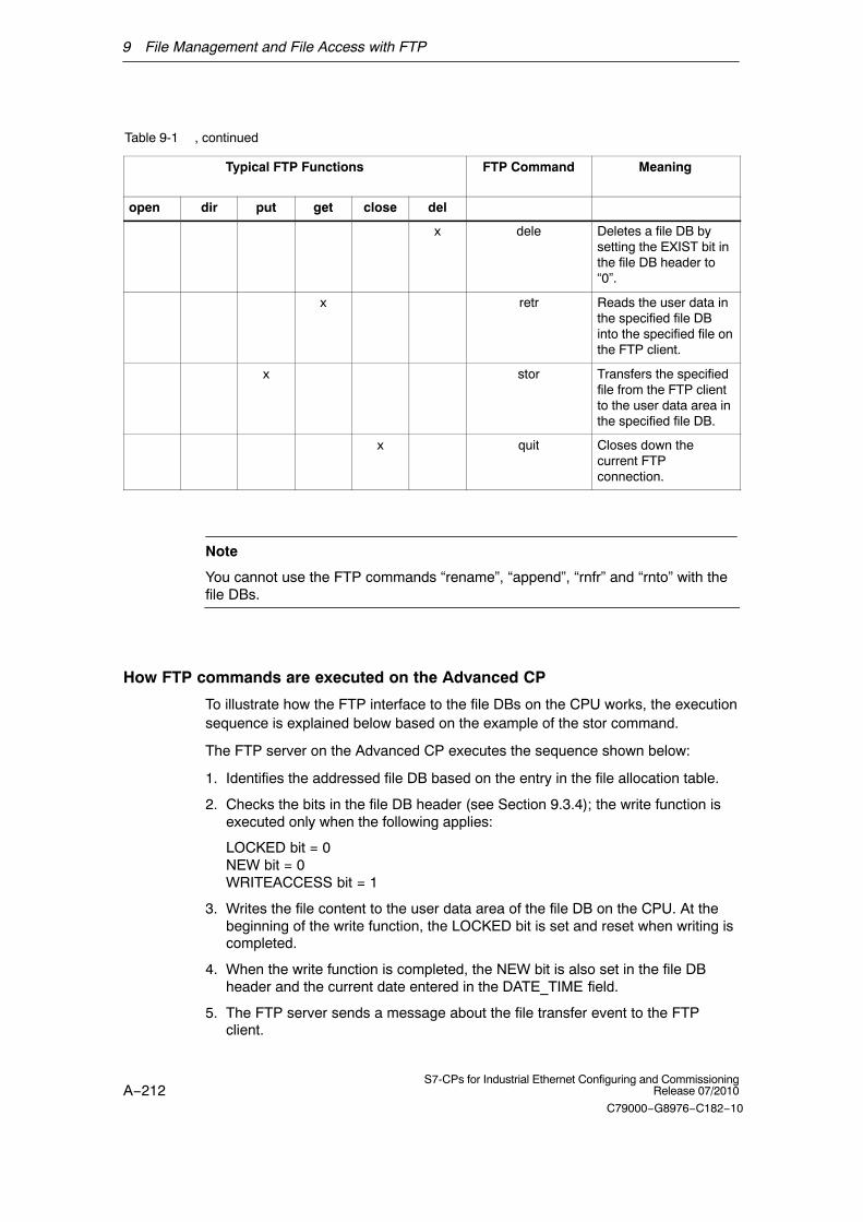
9 File Management and File Access with FTP
A−212S7-CPs for Industrial Ethernet Configuring and Commissioning
Release 07/2010
C79000−G8976−C182−10
Table 9-1 , continued
Typical FTP Functions MeaningFTP Command
open delclosegetputdir
x dele Deletes a file DB bysetting the EXIST bit inthe file DB header to“0”.
x retr Reads the user data inthe specified file DBinto the specified file onthe FTP client.
x stor Transfers the specifiedfile from the FTP clientto the user data area inthe specified file DB.
x quit Closes down thecurrent FTPconnection.
Note
You cannot use the FTP commands “rename”, “append”, “rnfr” and “rnto” with thefile DBs.
How FTP commands are executed on the Advanced CP
To illustrate how the FTP interface to the file DBs on the CPU works, the executionsequence is explained below based on the example of the stor command.
The FTP server on the Advanced CP executes the sequence shown below:
1. Identifies the addressed file DB based on the entry in the file allocation table.
2. Checks the bits in the file DB header (see Section 9.3.4); the write function isexecuted only when the following applies:
LOCKED bit = 0NEW bit = 0WRITEACCESS bit = 1
3. Writes the file content to the user data area of the file DB on the CPU. At thebeginning of the write function, the LOCKED bit is set and reset when writing iscompleted.
4. When the write function is completed, the NEW bit is also set in the file DBheader and the current date entered in the DATE_TIME field.
5. The FTP server sends a message about the file transfer event to the FTPclient.

9 File Management and File Access with FTP
A−213S7-CPs for Industrial Ethernet Configuring and CommissioningRelease 07/2010
C79000−G8976−C182−10
Notice
If you specify a file for the transfer that is not included in the file allocation table,the requested file system operation is executed on the current folder.
Transfer mode for file transfer
File transfer only uses the binary mode. To change to this mode, enter thecommand ”binary” in the input console after logging on.
9.3.3 File allocation table
Meaning
In the FTP server role, the Advanced CP requires information on how the datablocks used in the S7 station for file transfer are mapped to files. You store this fileassignment table in the file_db.txt file in the file system of the Advanced CP.
Structure
The file allocation table contains two areas in which the assignments are enteredrow−oriented as shown in the example below:
� Rack/slot assignment of the CPU
� DB assignment
Notes on the syntax
� Relevant rows can be recognized by the character string “cpux” (where x = acharacter “1−4”); this applies to both areas.
Notice
Please note the use of lower−case letters. Otherwise the files will not berecognized.
Please use a text editor that does not create invisible control characters or savethe data in the TXT mode so that no invisible control characters are stored.
� Valid separators for the entries are ”blanks” or ”tabs”.
� All other characters are interpreted as comment characters.
� The following applies to the file name of a file DB:
− Length: maximum 64 characters;

9 File Management and File Access with FTP
A−214S7-CPs for Industrial Ethernet Configuring and Commissioning
Release 07/2010
C79000−G8976−C182−10
− Permitted characters: Letters “A−Z,a−z”; numbers “0−9”, “_”, “.”
� Row length: maximum of 256 characters
# CONFIGURATION FILE for file transfer between an FTP client of a remote system# and an S7−CPU using the FTP server of the Advanced CP
# This is an ASCII file and may be edited.# This file must be located in the directory ”/config” of the file system# of the Advanced CP. Its file name must be ”file_db.txt” (all lowercase).
# All lines that do not begin with ”cpu” (lowercase AND no leading blanks) # are interpreted as comment.# Maximum length per line is 256 characters.# Delimiters are (one or more) blanks or tabs.
# The following table defines the rack and slot of the CPU(s).# Definitions of ”cpu1”, ”cpu2”, ”cpu3” and ”cpu4” are allowed.
# CPU Rack Slot # −−−−−−−−−−−−−−−−−−−−−−−−−−−−−cpu1 0 4cpu2 0 7
# The following table defines pairs of file names and file DBs in the CPU.# The maximum number of pairs is 100. # The file name must begin with ”cpuX” (where X = 1, 2, 3 or 4).# Note that ”cpuX” must be defined in the table above!# The file name must consist of the characters ”a−z”, ”A−Z”, ”0−9”, ”_” or ”.”# It must not include a path. The maximum length of a file name is 64 characters.
# File Name File DB Number# −−−−−−−−−−−−−−−−−−−−−−−−−−−−−−−−−−−−−−−−cpu1db20 20cpu1db35 35cpu2_test.dat 5
Example:
Rack/slotassignment
DB assignment
In the example shown here, the FTP command
C:> PUT s7daten.txt cpu1db35
is used to transfer the s7daten.txt file to DB35 (file DB) that must be located onCPU1.
How to create and manage the file allocation table
The file file_db.txt is located in the file system of your Advanced CP in the folder/config. You can upload the file as originally shipped with your CP to your PG/PCand use it as a template for your application. You will also find the sample text inthe properties dialog of the CP in the “FTP” tab.
You can manage this file with the normal FTP commands as described in Section9.2 for the IT file system.

9 File Management and File Access with FTP
A−215S7-CPs for Industrial Ethernet Configuring and CommissioningRelease 07/2010
C79000−G8976−C182−10
If the file file_db.txt does not exist, it is not possible to access file DBs using theFTP server of the Advanced CP. After editing the file and transferring it to the filesystem of the Advanced CP, you should therefore make sure that the transfer wassuccessful.
If both the transfer and syntax were correct, the following message is displayed:“226 Transfer ok; closing data connection”
If the syntax is incorrect, a message similar to the one shown below will bedisplayed:
“450 Requested action aborted − configuration file error in line 16”
If an error was reported, check your system configuration and repeat the transfer.You can check your configuration with the following command:ftp> dir cpux (where x = 1−4)
Notice
Please note the use of lower−case letters. Otherwise the files will not berecognized.

9 File Management and File Access with FTP
A−216S7-CPs for Industrial Ethernet Configuring and Commissioning
Release 07/2010
C79000−G8976−C182−10
Example
With the configured CPU directories, the file name is displayed. This can includethe number of the corresponding file DB.

9 File Management and File Access with FTP
A−217S7-CPs for Industrial Ethernet Configuring and CommissioningRelease 07/2010
C79000−G8976−C182−10
Meaning of the flags of ”cpu” folders with the dir command:
� −r− −r− −r− − (read flag) :
If this flag is displayed, the EXIST bit is set in the file DB. It is possible to readthis file DB as long as the LOCKED bit is not set.
� − −w− −w− −w− (write flag):
If this flag is displayed, the NEW bit is not set in the file DB and theWRITEACCESS bit is set. It is possible to write this file DB as long as theLOCKED bit is not set.
� l− − − − − − − − − (locked flag):
If this flag is displayed, the LOCKED bit is set in the file DB. Neither reading norwriting the file DB is possible. If the ”r” or ”w” flags are set in addition to thisflag, this means that reading or writing will be possible if the LOCKED bit iscleared.
If a file DB does not physically exist but is configured in the file allocation table”file_db.txt”, all the flags are reset in the display (display: − − − − − − − − − −) andthe file size is indicated as 0 bytes.
Note
It is possible to change from one folder to another on the CPU. Remember,however, that only the commands listed in Table 9-1 can be executed.

9 File Management and File Access with FTP
A−218S7-CPs for Industrial Ethernet Configuring and Commissioning
Release 07/2010
C79000−G8976−C182−10
9.3.4 Structure of the data blocks (File DB) for FTP services
Method
To allow the transfer of data with FTP, you create data blocks (file DBs) in the CPUof your S7 station. These data blocks must have a specific structure so that theycan be used as transferable files by the FTP services. These blocks consist of thefollowing sections:
� Section 1: File DB header (has a fixed length (20 bytes) and structure)
� Section 2: User data (variable length and structure)
File DB header for FTP server operation
Note: The file DB header described here is largely identical to the file DB headerfor client operation described in Table 9-4; the differences relate to the followingparameters:
� WRITEACCESS
� FTP_REPLY_CODE
Table 9-2
Parameter Type Value / Meaning Set by
EXIST BOOL The EXIST bit indicateswhether the user data areacontains valid data.
The retrieve FTP commandexecutes the job only whenEXIST=1.
� 0: The file DB does notcontain valid user data (”filedoes not exist”).
� 1:The file DB contains validuser data (”file exists”).
The dele FTP command sets EXIST=0
The stor FTP command sets EXIST=1

9 File Management and File Access with FTP
A−219S7-CPs for Industrial Ethernet Configuring and CommissioningRelease 07/2010
C79000−G8976−C182−10
Table 9-2 , continued
Parameter Set byValue / MeaningType
LOCKED BOOL The LOCKED bit is used torestrict access to the file DB.
� 0:The file DB can beaccessed.
� 1:The file DB is locked.
The stor and retr FTP commands setLOCKED=1 when they are executed.
The following function is also possiblewhen writing from the user program:
The user program on the S7 CPU canset or reset LOCKED during writeaccess to achieve data consistency.
Recommended sequence in the userprogram:
1. Query LOCKED bit;
If =0
2. Set WRITEACCESS Bit=0
3. Query LOCKED bit;
If =0
4. Set LOCKED Bit=1
5. Write data
6. Set LOCKED Bit=0
NEW BOOL The NEW bit indicates whetherdata have been modified sincethe last read access.
� 0:
The content of the file DB isunchanged since the lastwrite access. The userprogram of the S7 CPU hasregistered the lastmodification.
� 1:
The user program of the S7CPU has not yet registeredthe last write access.
After execution, the stor FTP commandsets NEW=1
The user program on the S7 CPU mustset NEW=0 after the data have beenread to allow a new stor or allow the fileto be deleted with the dele FTPcommand.
WRITEACCESS BOOL 0:The FTP client on the PG/PChas no write access rights forthe file DBs on the S7 CPU.
1:The FTP client on the PG/PChas write access rights for thefile DBs on the S7 CPU.
During the configuration of the DB, thebit is set to an initialization value.
Recommendation:
Whenever possible, the bit shouldremain unchanged! In special situations,adaptation during operation is possible.
ACT_LENGTH DINT Current length of the user dataarea.
The content of this field is onlyvalid when EXIST = 1.
The current length is updated followingwrite access.
MAX_LENGTH DINT Maximum length of the userdata area (length of the entireDB less 20 bytes header).
The maximum length should bespecified during configuration of the DB.
The value can also be modified by theuser program during operation.

9 File Management and File Access with FTP
A−220S7-CPs for Industrial Ethernet Configuring and Commissioning
Release 07/2010
C79000−G8976−C182−10
Table 9-2 , continued
Parameter Set byValue / MeaningType
FTP_REPLY_CODE
INT This parameter is irrelevant inFTP server operation.
Is set to ”0” by the FTP server.
DATE_TIME DATE_AND_TIME
Date and time of the lastmodification to the file.
The content of this field is onlyvalid when EXIST = 1.
The current date is updated following awrite access.
If the function for forwarding the time ofday is used, the entry corresponds tothe time that was passed on.
If the function for forwarding the time ofday is not used, a relative time isentered. This time relates to the startupof the Advanced CP (the initializationvalue is 1.1.1994 0.0 (midnight)).
Example and reference for the file DB header
After installing STEP 7, you will find a predefined data type (UDT1 =FILE_DB_HEADER) in the block library that you can copy to your STEP 7 projectand reference directly as a header in a file DB.
In the declaration, you will see the following structure.
Table 9-3
Address Name Type Initial value Comment
0.0 STRUCT
+0.0 bit08 BOOL FALSE Reserved
+0.1 bit09 BOOL FALSE Reserved
+0.2 bit10 BOOL FALSE Reserved
+0.3 bit11 BOOL FALSE Reserved
+0.4 bit12 BOOL FALSE Reserved
+0.5 bit13 BOOL FALSE Reserved
+0.6 bit14 BOOL FALSE Reserved
+0.7 bit15 BOOL FALSE Reserved
+1.0 EXIST BOOL FALSE if TRUE: FileDB content is validdata
+1.1 LOCKED BOOL FALSE it TRUE: FileDB is locked causedby changes of the content
+1.2 NEW BOOL FALSE if TRUE: FileDB content is new andmay not be overwritten
+1.3 WRITEACCESS BOOL FALSE if TRUE: FTP server of the IT−CPhas write access, else FTP server
+1.4 bit04 BOOL FALSE Reserved

9 File Management and File Access with FTP
A−221S7-CPs for Industrial Ethernet Configuring and CommissioningRelease 07/2010
C79000−G8976−C182−10
Table 9-3 , continued
Address CommentInitial valueTypeName
+1.5 bit05 BOOL FALSE Reserved
+1.6 bit06 BOOL FALSE Reserved
+1.7 bit07 BOOL FALSE Reserved
+2.0 ACT_LENGTH DINT L#0 current size of the content in bytes(not including the header of 20bytes)
+6.0 MAX_LENGTH DINT L#0 current size of the content in bytes(not including the header of 20bytes)
+10.0 FTP_REPLY_CODE INT 0 last reply code from the remote FTPserver
+12.0 DATE_TIME DATE_AND_TIME DT#00−1−1−0:0:0.000 date and time of last change of thecontent of the FileDB
=20.0 END_STRUCT

9 File Management and File Access with FTP
A−222S7-CPs for Industrial Ethernet Configuring and Commissioning
Release 07/2010
C79000−G8976−C182−10
9.4 The Advanced CP as FTP client for S7 CPU data
9.4.1 Method
To transfer data using FTP, you create data blocks (file DBs) in the CPU of your S7station (for structure, refer to Section 9.3.4).
The user program sends FTP jobs that are executed by the Advanced CP as anFTP client. Depending on the module type of the Advanced CP, you can useFC40...44 or FB40 in the user program (see Section 9.4.4).
The data are transferred on FTP connections. FTP connections are special TCPconnections that you configure in STEP 7 / NetPro.
In the job, among other things, you specify the IP address of the FTP server, thestorage location of the file on the FTP server and the file name along with accessinformation.
The following schematics illustrate how the function works when using FC40...44or FB40.
FTP server
DB127
DB243
DB244
Header
User data
FTP client:S7 station with Advanced CP
File DBs
User program
CALL FC40
CALL FC42
CALL FC44
S7 − 300
S7 − 400FTP connection
FTP_RETRIEVE
FTP_STORE
Figure 9-3 How FTP data transmission works when using FC40...44
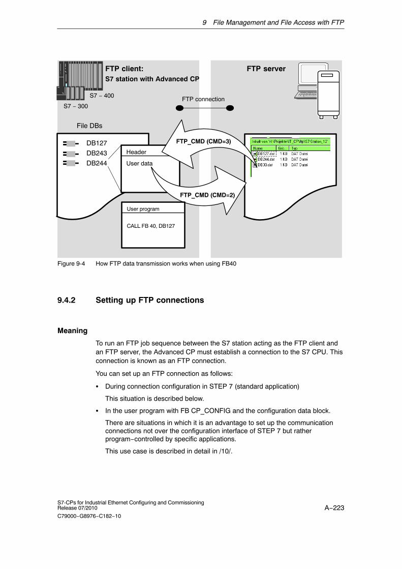
9 File Management and File Access with FTP
A−223S7-CPs for Industrial Ethernet Configuring and CommissioningRelease 07/2010
C79000−G8976−C182−10
FTP server
DB127
DB243
DB244
Header
User data
FTP client:S7 station with Advanced CP
File DBs
User program
CALL FB 40, DB127
S7 − 300
S7 − 400FTP connection
FTP_CMD (CMD=3)
FTP_CMD (CMD=2)
Figure 9-4 How FTP data transmission works when using FB40
9.4.2 Setting up FTP connections
Meaning
To run an FTP job sequence between the S7 station acting as the FTP client andan FTP server, the Advanced CP must establish a connection to the S7 CPU. Thisconnection is known as an FTP connection.
You can set up an FTP connection as follows:
� During connection configuration in STEP 7 (standard application)
This situation is described below.
� In the user program with FB CP_CONFIG and the configuration data block.
There are situations in which it is an advantage to set up the communicationconnections not over the configuration interface of STEP 7 but ratherprogram−controlled by specific applications.
This use case is described in detail in /10/.

9 File Management and File Access with FTP
A−224S7-CPs for Industrial Ethernet Configuring and Commissioning
Release 07/2010
C79000−G8976−C182−10
How to configure FTP connections
To use FTP functionality, you require TCP connections with special properties.Follow the steps outlined below to configure the connection in STEP 7 / NetPro:
1. Create a TCP connection with an unspecified connection partner for the CPU inyour S7 station.
Use for FTP protocol
2. Select the option ”Use for FTP protocol”
Selecting this option has the following consequences:
− The TCP connection is now used as an FTP connection.
− ”Addresses” tab: The addresses are specified automatically (Port=21)
− ”Options” tab: The mode is set permanently to FTP.

9 File Management and File Access with FTP
A−225S7-CPs for Industrial Ethernet Configuring and CommissioningRelease 07/2010
C79000−G8976−C182−10
9.4.3 Structure of the data blocks (File DB) for FTP services
Method
To allow the transfer of data with FTP, you create data blocks (file DBs) in the CPUof your S7 station. These data blocks must have a specific structure so that theycan be used as transferable files by the FTP services. These blocks consist of thefollowing sections:
� Section 1: File DB header (has a fixed structure and a length of 20 bytes).
� Section 2: User data (variable length and structure)
File DB header for FTP client operation
Note: The file DB header described here is largely identical to the file DB headerfor server operation described in Table 9-2; the differences relate to the followingparameters:
� WRITEACCESS
� FTP_REPLY_CODE
Table 9-4
Parameter Type Value / Meaning Set by
EXIST BOOL The EXIST bit indicateswhether the user data areacontains valid data.
The retrieve FTP commandexecutes the job only whenEXIST=1.
� 0: The file DB does notcontain valid user data (”filedoes not exist”).
� 1:The file DB contains validuser data (”file exists”).
The dele FTP command sets EXIST=0
The stor FTP command sets EXIST=1

9 File Management and File Access with FTP
A−226S7-CPs for Industrial Ethernet Configuring and Commissioning
Release 07/2010
C79000−G8976−C182−10
Table 9-4 , continued
Parameter Set byValue / MeaningType
LOCKED BOOL The LOCKED bit is used torestrict access to the file DB.
� 0:The file DB can beaccessed.
� 1:The file DB is locked.
The stor and retr FTP commands setLOCKED=1 when they are executed.
The following function is also possiblewhen writing from the user program:
The user program on the S7 CPU canset or reset LOCKED during writeaccess to achieve data consistency.
Recommended sequence in the userprogram:
1. Query LOCKED bit;
If =0
2. Set WRITEACCESS Bit=0
3. Query LOCKED bit;
If =0
4. Set LOCKED Bit=1
5. Write data
6. Set LOCKED Bit=0
NEW BOOL The NEW bit indicates whetherdata have been modified sincethe last read access.
� 0:
The content of the file DB isunchanged since the lastwrite access. The userprogram of the S7 CPU hasregistered the lastmodification.
� 1:
The user program of the S7CPU has not yet registeredthe last write access.
After execution, the stor FTP commandsets NEW=1
The user program on the S7 CPU mustset NEW=0 after the data have beenread to allow a new stor or allow the fileto be deleted with the dele FTPcommand.
WRITEACCESS BOOL 0:The user program (FTP clientblocks) has write access to fileDBs on the S7 CPU.
1:The user program (FTP clientblocks) has no write access tofile DBs on the S7 CPU.
During the configuration of the DB, thebit is set to an initialization value.
Recommendation:
Whenever possible, the bit shouldremain unchanged! In special situations,adaptation during operation is possible.
ACT_LENGTH DINT Current length of the user dataarea.
The content of this field is onlyvalid when EXIST = 1.
The current length is updated followingwrite access.
MAX_LENGTH DINT Maximum length of the userdata area (length of the entireDB less 20 bytes header).
The maximum length should bespecified during configuration of the DB.
The value can also be modified by theuser program during operation.

9 File Management and File Access with FTP
A−227S7-CPs for Industrial Ethernet Configuring and CommissioningRelease 07/2010
C79000−G8976−C182−10
Table 9-4 , continued
Parameter Set byValue / MeaningType
FTP_REPLY_CODE
INT Unsigned integer (16−bit)containing the last reply codefrom FTP as a binary value.
The content of this field is onlyvalid when EXIST = 1.
This is updated by the FTP client whenthe FTP command is executed.
DATE_TIME DATE_AND_TIME
Date and time of the lastmodification to the file.
The content of this field is onlyvalid when EXIST = 1.
The current date is updated following awrite access.
If the function for forwarding the time ofday is used, the entry corresponds tothe time that was passed on.
If the function for forwarding the time ofday is not used, a relative time isentered. This time relates to the startupof the Advanced CP (the initializationvalue is 1.1.1994 0.0 (midnight)).
Example and reference for the file DB header: see Section 9.3.4

9 File Management and File Access with FTP
A−228S7-CPs for Industrial Ethernet Configuring and Commissioning
Release 07/2010
C79000−G8976−C182−10
9.4.4 FCs and FBs for FTP services
Using the blocks
For data transmission using FTP, the user program uses either FC40...44 or FB40.
Depending on the module type of the Advanced CP, either FC40...44 or FB40 canbe used in the user program:
� FB40
FB40 is available as of STEP 7 V5.4 SP4. It can be used as of the followingmodule types:
− As of CP 343−1 Advanced (GX30)
− As of CP 443−1 Advanced (GX20)
These module types continue to support FC40...44.
The module types listed below, on the other hand, do not support FB40:
− Advanced CPs up to CP 343–1 Advanced (GX21)
− Advanced−CPs up to CP 443–1 Advanced (EX41)
� FC40...44
The FCs can be used with all Advanced CPs.
Using FB40 has the following advantages:
� Simplification in the user program due to working with command variablesinstead of differing function calls
� Additional function “APPEND”
“APPEND” allows data to be appended to an existing file.
� Additional function “RETR_PART”
“RETR_PART” allows data areas to be selected and read from a file.
Further information
The blocks are described in detail in /10/. There, you will also find sampleprograms.

A−229S7-CPs for Industrial Ethernet Configuring and CommissioningRelease 07/2010
C79000−G8976−C182−10
10 CP as Web Server: HTML Process Control
Note
The term “S7 applet” is used generally for applets.
Use the S7 beans for communication with the Advanced CP.
The Advanced CP provides you with the function of a Web server for access usinga Web browser.
For this purpose, the Advanced CP has a storage area for files. This area is usedto store HTML pages and S7 applets.
HTML pages are used to indicate and display information in a Web browser. S7applets are Java applets specially written for SIMATIC S7 and that used to allowwrite or read access to the S7−CPU.
When supplied, the Advanced CP has S7 beans and other information in the filesystem.
This chapter answers the following questions:
� How are the HTML pages supplied with the Advanced CP used to accessinformation on the S7 station?
� What options exist to adapt HTML process control to my individualrequirements?
� What security measures can I take or do I need to take to prevent unauthorizedaccess to process data?
� How do I store my own HTML pages?
10.1 Overview of HTML process control
Multilevel concept
The Advanced CP provides several levels to implement device and process datamonitoring with HTML pages:
System pages via Web browser(system diagnostics only)
Individual solutions with S7 beans

10 CP as Web Server: HTML Process Control
A−230S7-CPs for Industrial Ethernet Configuring and Commissioning
Release 07/2010
C79000−G8976−C182−10
Individual solutions with S7 beans / individual S7 applets
You want to use graphics options adapted to your application and create morecomplex applets.
You not only want to display your process data in the plant pictures but also wantto use the data, for example, for evaluation in a database.
You can achieve this with the following options:
� Create application-specific S7 applets using the preprogrammed S7 beans.
� Create Java source code; use application-specific applets, Java beans and thesupplied S7 beans.
You will find a detailed description in the manual on the S7 applets / beans /18/.
Extended access and display options − The Java Beans concept
The Java Beans concept allows you to create objects (Java components) and tolink them simply to executable programs.
There is an S7 beans class library available for the Advanced CP (S7BeansAPI).The object classes contained in this library can be used for object-oriented accessto a variety of information on the SIMATIC S7 and for graphic display of processvariables.
The S7 beans class library provides an open interface allowing you to extendprocess data evaluation for example with databases, table calculation ormanagement information systems.
Organizing files − resources of the Advanced CP
The Advanced CP has memory available for storing your HTML pages. You willfind information on this topic in the device manual of the Advanced CP /1/.
Please note the information in the “readme.htm” file on the Advanced CP.
This contains information about the meaning and purpose of the shipped files. Youcan then decide which files might be useful for your application. Using FTPfunctions, you can organize the files on the Advanced CP to suit yourrequirements.

10 CP as Web Server: HTML Process Control
A−231S7-CPs for Industrial Ethernet Configuring and CommissioningRelease 07/2010
C79000−G8976−C182−10
10.2 Security when Accessing Process Data
Guaranteeing information security
The access to process data by the Advanced CP via Internet brings with it thedanger of misuse. You should therefore always protect process data not only withpasswords but also by restricting access to your network with suitable securitymechanisms.
10.2.1 Opening ports on the Advanced CP during configuration
Ro be able to use the IT functions of the Advanced CP, the relevant ports of theCP must be enabled in the configuration (HW Config > properties dialog of the CP> “IP Access Protection” tab).
� Activate Web server
This opens port 80 of the CP.
� Activate FTP server
This opens port 21 of the CP.
As default, the ports are enabled. To disable the ports, deselect the options.
10.2.2 Operation with firewall and proxy server
The operation of an internal company network (Intranet) is normally protectedagainst external, uncontrolled access by a firewall. Operation with a firewall ispossible if the IP addresses set in the S7 applets can pass through the filtermechanism of the firewall.
To make use of the full functionality of the Advanced CP, make sure that therelevant ports of the communication partner of the Advanced CP are opened. Thefollowing table lists the ports and functions:
Table 10-1
TCP Port to beenabled
Function used Enabling required for access indirection
80 Access to an HTML page on the AdvancedCP or on a Web server (the Advanced CP orWeb server is the HTTP server).
Web browser with firewall −> CP
25 Access by the mail client (Advanced CP isSMTP client) to a mail server (SMTP server).
CP −> mail server with firewall
(enabled on the mail server)

10 CP as Web Server: HTML Process Control
A−232S7-CPs for Industrial Ethernet Configuring and Commissioning
Release 07/2010
C79000−G8976−C182−10
Table 10-1 , (Fortsetzung)
TCP Port to beenabled
Enabling required for access indirection
Function used
20 and 21 File access:
Access to files on the Advanced CP usingFTP functions (Advanced CP is the FTPserver or client).
FTP client with firewall −> CP
CP −> FTP server with firewall
10.2.3 Level of password protection
It is generally the case that different groups of people require different types ofaccess to process data. To protect your process data from unauthorized access,you can restrict access to the process data to authorized users when you configurethe CP.
In the ”Users” tab of the CP properties dialog, you can set the access rights forindividual users graded according to functions (see Section 3.4.9).
When data on the CP is accessed, there is then a password query.
10 CP as Web Server: HTML Process Control
A−233S7-CPs for Industrial Ethernet Configuring and CommissioningRelease 07/2010
C79000−G8976−C182−10
10.3 Accessing the Advanced CP via a Web browser
Hoe to access the Advanced CP via a Web browser
The basis of communication via an intranet or the Internet is the Internet TCP/IPprotocol that is implemented on the Advanced CP. In principle, the following fewsteps are all that is necessary to make your plant accessible via your intranet orthe Internet:
� For intranet and Internet communication
− Connect the Advanced CP to Industrial Ethernet.
− During configuration of the hardware, assign an IP address to the AdvancedCP.
� In addition, for Internet communication
You connect your manufacturing network to public transmission facilities usingsuitable connectivity devices, for example a router.
Generally, you create access to your own company intranet. This already hasthe required protection mechanisms on the interface to Internet (firewall).
For information on opening ports, see Section 10.2.
Web browser requirements profile
To access the HTML pages on the Advanced CP as a Web server you require aWeb browser on your PG/PC/MOBIC, for example Internet Explorer. The Webbrowser must meet the following requirements:
� JDK (Java Development Kit) 1.1.X is supported.
The Internet Explorer meets these requirements. Other Web browsers with thesame range of functions can also be used. You will find the supported Webbrowsers in the device manual of your CP (/1/).
Note
JDK 1.2.x, 1.3.x and 1.4.x are also supported. To use applets created specially forthese JDK versions with the Microsoft Internet Explorer, you do, however require aJava plug−in.
Other Web browsers may only meet these requirements with certain restrictions.With these Web browsers, you also require a plug-in component corresponding tothe Java reference implementation of a SUN Java Virtual Machine.
When using S7 beans, special settings must be made in the Web browser. You willfind more information on this topic and on the requirements outlined above in thedocuments on the S7 beans /17/ and /18/.

10 CP as Web Server: HTML Process Control
A−234S7-CPs for Industrial Ethernet Configuring and Commissioning
Release 07/2010
C79000−G8976−C182−10
URL: Uniform Resource Locator
In the World Wide Web, addressing using URL has become standard. You canalso contact the Advanced CP with your Web browser using the URL. This URLcan have almost any complexity but consists in principle of four essential parts.The following schematic illustrates the structure (typical URL) and shows thecontents for calling Advanced CPs.
Protocol Server name[:Port] [Folder] File name
Typical URL http://www.ad.siemens.de/net/page.htm
URL for Advanced CP
http://142.80.00.01/user/index.htm
HTTP protocol IP address [Folder] Name of theHTML page
When accessing the Advanced CP using a Web browser, use the HTTP protocol toaddress the Web server on the Advanced CP:
You inform the CP of the IP address during configuration with STEP 7 (see Section3.4). If you have an attachment from Industrial Ethernet to your intranet or to theInternet, the CP can be contacted using the IP address in the intranet or Internet.
A detailed description of the structure of the IP address and the options of creatingsubnets or subnet masks is beyond the scope of this manual. You will find moredetailed information in the STEP 7 online help and in the References in theAppendix.
Setting a proxy server on the PG/PC/MOBIC
For more information, check with your system administrator.

10 CP as Web Server: HTML Process Control
A−235S7-CPs for Industrial Ethernet Configuring and CommissioningRelease 07/2010
C79000−G8976−C182−10
10.4 Accessing HTML system pages − Examples
Basic information is available immediately
HTML system pages are HTML pages saved on the Advanced CP containingsystem information that you can display without any further adaptation using yourWeb browser.
The file system of the Advanced CP
The Advanced CP provides you with a file system consisting of volatile andnon−volatile memory. During operation, you can store your HTML pages and otherdata.
For more information on opening ports, refer to Section 10.2.
System pages
From the start page that you can adapt and replace by an application-specifichome page, you can call up other HTML pages.
The start page is available at http://<IP address>/index.htm.
If you have not stored you own start page, the start page of Web diagnosticsopens.
Access protection
The HTML system pages are protected by the access protection you configured onthe Advanced CP.
10.4.1 Querying the diagnostic buffer
For CPU and CP modules, you can query the last diagnostic messages using Webdiagnostics.

10 CP as Web Server: HTML Process Control
A−236S7-CPs for Industrial Ethernet Configuring and Commissioning
Release 07/2010
C79000−G8976−C182−10
Setting the language for the diagnostic buffer display (Advanced CP)
This function is available on several CPs with ready−made HTML pages, forexample the Advanced CPs. As default, the CP uses internal message texts inEnglish.
You can change the language of the diagnostic messages by copying the eventsdatabase from your STEP 7 installation on a PC/PG and storing it under thefollowing file name in the file system of the CP:
/config/S7wmeld.edb
(case−sensitive)
Within this folder there are files with the names S7wmeldA.edb, S7wmeldB.edb,S7wmeldC.edb, etc.
The last letter before the file extension is the identification letter for a language,assigned as follows:
A = German, B = English, C = French, D = Spanish and E = Italian
When copying the required file, please omit this last letter before the file extension.This procedure also allows you to update an out−of−date events database with anew STEP 7 installation.

10 CP as Web Server: HTML Process Control
A−237S7-CPs for Industrial Ethernet Configuring and CommissioningRelease 07/2010
C79000−G8976−C182−10
10.5 Creating and storing your own ”home page”
Flexible use of the Advanced CP file system
The existing start page provides you with basic functions that are adequate for alarge number of requirements.
The Advanced CP file system provides a flexible instrument for the presentation offunctions and data adapted to your plant. By creating your own start page, youhave the tool to extend the view to cover your entire plant or even further.
You can modify the existing start page or can replace it by your own home page.
Controller 1 Controller 2
Controller 1
Controller 2
Process picture 1
Process picture 2
Process picture 1
Process picture 2
Your own startpage couldresemble the oneshown here
Figure 10-1 Example of a customized home page

10 CP as Web Server: HTML Process Control
A−238S7-CPs for Industrial Ethernet Configuring and Commissioning
Release 07/2010
C79000−G8976−C182−10
Points to remember
Refer to the information in the manual of the Advanced CP /1/ regarding thefollowing points.
� The size of the file system is limited.
� The number of characters in the URLs to be specified is limited.
� The length of the file names is limited.
Including S7 Applets
Flexible access to distributed HTML system pages is one aspect of designing thehome page.
You have further opportunities for querying information if you include your own S7applets and the supplied S7 beans in your HTML pages.
Downloading HTML pages
Use the FTP file management functions (FTP client) to add to or replace theexisting HTML pages.

11 Web Diagnostics
A−239S7-CPs for Industrial Ethernet Configuring and CommissioningRelease 07/2010
C79000−G8976−C182−10
11 Web Diagnostics
With Web diagnostics, the CP provides you with the option of calling up the mostimportant settings of a connected station and the status of their networkconnections and communication partners from an HTTP client on a PG/PC. Youcan also query the diagnostic buffer entries of the modules of the rack in which theCP is located.
Using Web diagnostics, you can only read the data of the connected station.
11.1 Initial situation
Web browser
To access the HTML pages on the CP, you require a Web browser. The followingWeb browsers are suitable for communication with the CP (other browsers alsopossible):
� Internet Explorer (recommended version: 6.0 or higher)
� Opera (recommended version: 9.2 or higher)
� Firefox (recommended version: 2.0 or higher)
Settings for access to diagnostic data
Check the following settings that are necessary for access to the diagnostic data:
� To load diagnostic data, JavaScript must be enabled in the Internet browser.
� The browser must support frames.
� Cookies must be accepted.
� The browser should be set so that it downloads the current data from the serverautomatically each time it accesses a page.
In Internet Explorer, you will find these settings in the “Tools” menu � “InternetOptions” � “General” tab � “Temporary Internet Files” � “Settings” button.
� When using a firewall on your PG/PC, the following port must be enabled forWeb diagnostics: “http port 80/TCP”
� Activating Web server functionality
The Web server functionality must be activated in the STEP 7 configuration:
HW Config � properties dialog of the CP � “IP Access Protection” tab � “ActivateWeb server” option
As default, the Web server is activated and port 80 of the CP is opened forHTTP access.

11 Web Diagnostics
A−240S7-CPs for Industrial Ethernet Configuring and Commissioning
Release 07/2010
C79000−G8976−C182−10
If you want to block port 80, disable the ”Activate Web server function” option.This option is not available in STEP 7 for all CPs.
Note
Station or device names configured in STEP 7 with special characters (forexample umlauts ä, ü etc.) will not be correctly interpreted in Web diagnostics.
11.2 Setup and operation
Starting and working with Web diagnostics
Follow the steps outlined below to start Web diagnostics:
1. Connect your PC with the LAN to which the CP is connected.
2. Start the Internet browser and enter the following address in the address line ofyour Internet browser:
http:\\<IP address of the CP>
Web diagnostics opens with the “Start Page”.
3. Select the display language you require from the “Language” drop-down list boxat the top right. The following languages are available:
� English
� Deutsch
� Français
� Español
� Italiano
4. You open the other pages using the navigation panel to the left of the window.

11 Web Diagnostics
A−241S7-CPs for Industrial Ethernet Configuring and CommissioningRelease 07/2010
C79000−G8976−C182−10
Layout of the diagnostics pages
The title bar of each Web diagnostics page displays the STEP 7 station name ofthe S7 station in which the CP is located.
Above the navigation panel to the left, you can see the module type (here:“SIMATIC S7 CP”).
The spectacles icon at the top right is used for cyclic updating of Web diagnostics.If you click on the icon, the contents of the pages are updated every 30 seconds.
Figure 11-1 Example of a page of Web diagnostics, here: CP 443−1GX30, navigation “PROFINET IO”

11 Web Diagnostics
A−242S7-CPs for Industrial Ethernet Configuring and Commissioning
Release 07/2010
C79000−G8976−C182−10
11.3 Diagnostics pages of the CP
Note
The diagnostics pages described below are not all available for every CP type.
Depending on the CP type, you will find, for example, information on the device asPROFINET IO controller and/or PROFINET IO device in the navigation panelunder ”PROFINET IO”. If the CP supports various PROFINET IO modes, thisdepends on the specific configuration of the device.
11.3.1 Start page
Below the title bar of the start page, you can see the CP type (for example,CP 343−1 CX10).
“General” tab
This page displays general device data and the status of the connected CP.
Parameter Function
General
Station name Configured name of the station in which the CP is installed.
Module name Configured name of the module
Module type Name of the module type
STATUS
Operating mode Current mode of the CP:
� Starting
� RUN (CP in productive mode)
� Stopping
� STOP
� Stopped with error

11 Web Diagnostics
A−243S7-CPs for Industrial Ethernet Configuring and CommissioningRelease 07/2010
C79000−G8976−C182−10
“File System” tab
On this page, you will find information on the file system of an IT−CP.
Parameter Function
Settings
File system Displays the setting of “Match case (case sensitive)”
Flash file system ( / )
Memory capacity Total capacity of the non−volatile flash memory area
Free memory Free space in the flash file system
Files/folders Number of existing files and folders
Number of Inodes Maximum number of storable files
Free Inodes Number of locations still free for files
Defective blocks ofdata
Number of defective (unusable) blocks of data
Volatile RAM file system ( /ram )
Memory capacity Total capacity of the volatile RAM memory area
Free memory Free space in the RAM file system
Files/folders Number of existing files and folders
Number of Inodes Maximum number of storable files
Free Inodes Number of locations still free for files
In contrast to the flash area, the RAM can be written to and read from anynumber of times. The data in the RAM are retained as long as the IT−CP issupplied with power.
The RAM is intended to store data that change during operation and need to berecorded (data recording services). The RAM is also suitable for temporarystorage.

11 Web Diagnostics
A−244S7-CPs for Industrial Ethernet Configuring and Commissioning
Release 07/2010
C79000−G8976−C182−10
11.3.2 Identification
Here, you can see a variety of information on the CP for identification andmaintenance.
Parameter Function
Identification
Plant designation1)
Plant designation of the CP if this was configured.
Location identifier1)
Location identifier of the CP if this was configured.
Serial number Serial number of the CP
Order number Order number of the CP
Version
Hardware Hardware version of the module
Firmware Version of the firmware currently running1) A CP acting as PROFINET IO device can be informed of the plant designation and location identifier
by the PROFINET IO controller. using the “write data record” function. This is done using themaintenance data record “IM1” with index AFF1H.The “write data record” function is described in /10/ with the FCs for PROFINET IO.

11 Web Diagnostics
A−245S7-CPs for Industrial Ethernet Configuring and CommissioningRelease 07/2010
C79000−G8976−C182−10
11.3.3 Rack configuration
The slots of the station and general data along with the status of the devices isdisplayed here.
Parameter Function
Rack configuration (rack name, rack number)
Slot Slot of the individual modules in the rack
Status Status display of the relevant module:
� Green (OK, module in operation)
� Red (a problem has occurred)
� Yellow (module changed to STOP)
The last column “LED Status” contains more information.
Module name Name of the module configured in HW Config
Order number Order number of the module
Version Firmware version of the module
LED Status LED display of the module:
� Gray (inactive LED, the LED is off)
� Colored (active LED, the LED is lit)
The number of type of the LEDs depends on the particular module type. You willfind an explanation of the significance of the LEDs in the documentation for theparticular module.
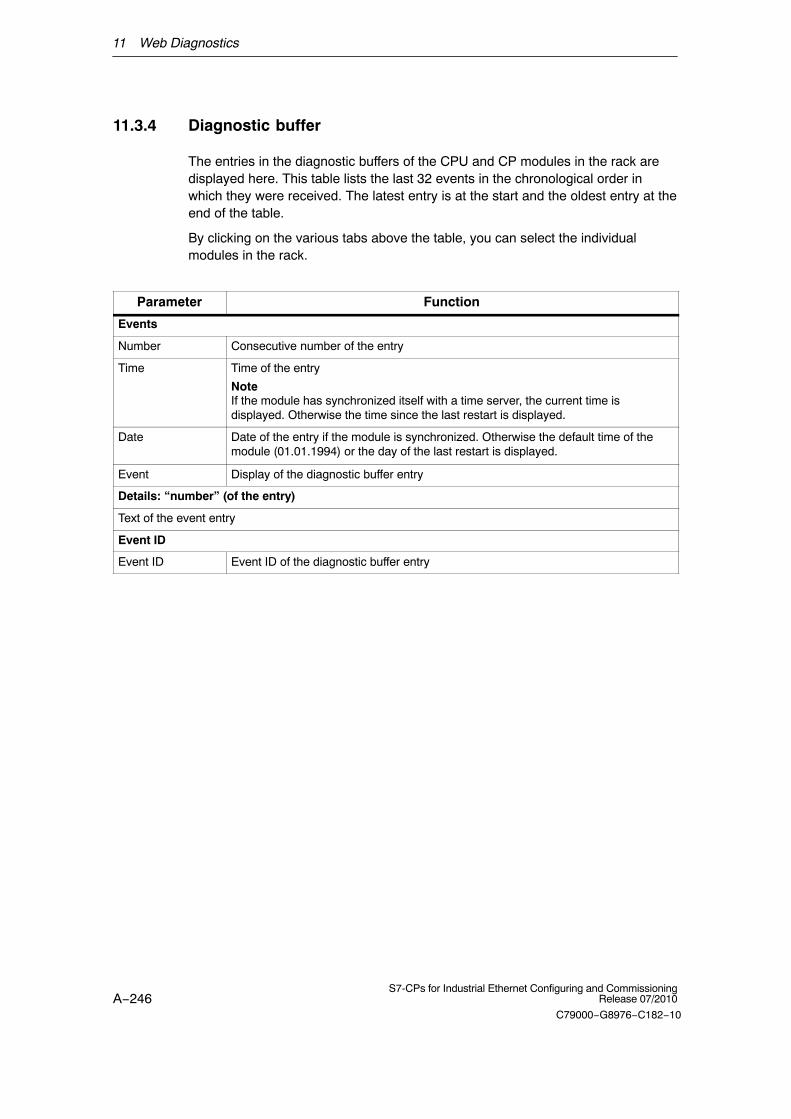
11 Web Diagnostics
A−246S7-CPs for Industrial Ethernet Configuring and Commissioning
Release 07/2010
C79000−G8976−C182−10
11.3.4 Diagnostic buffer
The entries in the diagnostic buffers of the CPU and CP modules in the rack aredisplayed here. This table lists the last 32 events in the chronological order inwhich they were received. The latest entry is at the start and the oldest entry at theend of the table.
By clicking on the various tabs above the table, you can select the individualmodules in the rack.
Parameter Function
Events
Number Consecutive number of the entry
Time Time of the entry
NoteIf the module has synchronized itself with a time server, the current time isdisplayed. Otherwise the time since the last restart is displayed.
Date Date of the entry if the module is synchronized. Otherwise the default time of themodule (01.01.1994) or the day of the last restart is displayed.
Event Display of the diagnostic buffer entry
Details: “number” (of the entry)
Text of the event entry
Event ID
Event ID Event ID of the diagnostic buffer entry
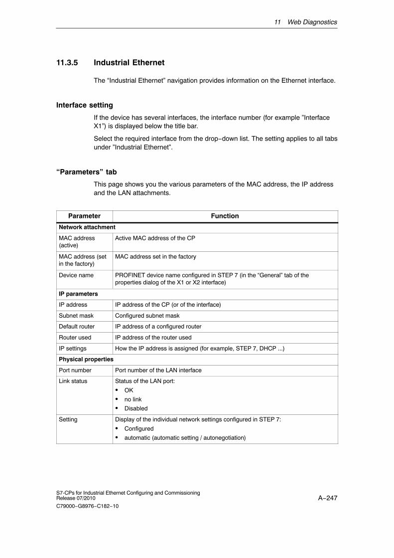
11 Web Diagnostics
A−247S7-CPs for Industrial Ethernet Configuring and CommissioningRelease 07/2010
C79000−G8976−C182−10
11.3.5 Industrial Ethernet
The “Industrial Ethernet” navigation provides information on the Ethernet interface.
Interface setting
If the device has several interfaces, the interface number (for example ”InterfaceX1”) is displayed below the title bar.
Select the required interface from the drop−down list. The setting applies to all tabsunder ”Industrial Ethernet”.
“Parameters” tab
This page shows you the various parameters of the MAC address, the IP addressand the LAN attachments.
Parameter Function
Network attachment
MAC address (active)
Active MAC address of the CP
MAC address (setin the factory)
MAC address set in the factory
Device name PROFINET device name configured in STEP 7 (in the “General” tab of theproperties dialog of the X1 or X2 interface)
IP parameters
IP address IP address of the CP (or of the interface)
Subnet mask Configured subnet mask
Default router IP address of a configured router
Router used IP address of the router used
IP settings How the IP address is assigned (for example, STEP 7, DHCP ...)
Physical properties
Port number Port number of the LAN interface
Link status Status of the LAN port:
� OK
� no link
� Disabled
Setting Display of the individual network settings configured in STEP 7:
� Configured
� automatic (automatic setting / autonegotiation)

11 Web Diagnostics
A−248S7-CPs for Industrial Ethernet Configuring and Commissioning
Release 07/2010
C79000−G8976−C182−10
Parameter Function
Mode Displays the current network properties (transmission rate and direction). Possiblevalues:
� 10 Mbps half duplex
� 10 Mbps full duplex
� 100 Mbps half duplex
� 100 Mbps full duplex
� 1 Gbps full duplex
� Mode when using media redundancy (for details, refer to “media redundancy”navigation)
Media redundancy Display of the role and with the manager, the ring status:
� Manager: Ring closed
� Manager: Ring open
� Client
“Statistics” tab
This page provides information about the number of sent or received frames sincethe module was last restarted. For multiport switches, the display is port−specific.
Parameter Function
Data packets sent
Number of error-free frames sent, number of unicast, multicast and broadcast frames and the framescanceled due to a collision
Received data packets
Number of error-free received frames, received unicast, multicast and broadcast frames, frames rejecteddue to checksum or alignment errors and frames rejected due to a lack of resources
“TCP Connections” tab
This page informs you about existing TCP connections.
Parameter Function
Number Consecutive number of the TCP connection
Local IP address IP address of the CP
Partner IP address Partner IP address
local port Number of the port used for the TCP connection

11 Web Diagnostics
A−249S7-CPs for Industrial Ethernet Configuring and CommissioningRelease 07/2010
C79000−G8976−C182−10
Parameter Function
Partner port Number of the port on the partner used for the TCP connection
Status Connection status of the TCP connection, for example:
� LISTEN (waiting for connection)
� ESTABLISHED (existing connection)
� TIME WAIT (wait state prior to connection termination) and
� other interim statuses such as SYN SENT, SYN RECV, CLOSING etc.)
“UDP Connections” tab
This page informs you about existing UDP connections.
Parameter Function
Number Consecutive number of the UDP connection
Local IP address IP address of the CP
Partner IP address Partner IP address
local port Number of the port used for the UDP connection
Partner port Number of the port on the partner used for the UDP connection

11 Web Diagnostics
A−250S7-CPs for Industrial Ethernet Configuring and Commissioning
Release 07/2010
C79000−G8976−C182−10
11.3.6 PROFINET IO
This page provides you with information on the most important parameters of thePROFINET IO configuration. Whether and which parameters are shown dependson whether the CP is configured as a PROFINET IO controller and/or device.
Select individual devices in the device list using the mouse to obtain information onthe underlying submodules of the device in the ”Submodule” list displayed below(not available for all CPs).
Parameters of a PROFINET IO controller
Parameter Function
PROFINET IO configuration
Mode PROFINET IO mode of the CP (here: PROFINET IO controller):
� PROFINET IO controller
� PROFINET IO device
� No PROFINET IO configuration
Device name PROFINET device name configured in STEP 7 (in the “General” tab of theproperties dialog of the X1 or X2 interface)
IP address IP address of the CP (or of the interface)
LED Status Mode of the controller (RUN, STOP, BUS1F, BUS2F, MAINT)
Device list
Device number Configured device number of the device in the PROFINET IO system
Device name Device name (STEP 7, properties dialog, “PROFINET” tab)
IP address IP address of the device
In the case of the IE/PB Link PN IO, the DP slaves are integrated via the proxy as aPROFINET IO device, in other words, they have different device numbers but allhave the same IP address of the IE/PB Link PN IO.
Diagnostic address Module base address (diagnostic address) of the relevant device
Status Status of the device:
� OK (problem-free operation)
� disrupted (error/fault)
Device number and device name of the selected device (see also “Device list”)
Slot Virtual slot of the relevant submodule
I address Address of the input data of the CPU
Q address Address of the output data of the CPU
Diagnostic address Diagnostic address of the relevant submodule (slot−specific)
Status Status of the submodule:
� OK (problem-free operation)
� disrupted (error/fault)

11 Web Diagnostics
A−251S7-CPs for Industrial Ethernet Configuring and CommissioningRelease 07/2010
C79000−G8976−C182−10
Parameters of a PROFINET IO device
Parameter Function
PROFINET IO configuration
Mode PROFINET IO mode of the CP (here: PROFINET IO device):
� PROFINET IO controller
� PROFINET IO device
� No PROFINET IO configuration
Device name Device name
IP address IP address of the CP (or of the interface)
Status Status of the device:
� OK(problem-free operation)
� No connection to PROFINET IO controller(connection disrupted or broken down)
� PROFINET IO blocks are not called correctly(the blocks are not called or not correctly called)
Assigned PNIO controller
Device name Device name of the assigned controller
IP address IP address of the controller
Details:
Slot Virtual slot of the relevant input/output submodule
I address Virtual address of the input submodules *)
Q address Virtual address of the output submodules *)
Status Status of the submodule:
� OK (problem-free operation)
� disrupted (error/fault)
*) These addresses appear in the user program in the data block called by the function that executedthe data transfer.

11 Web Diagnostics
A−252S7-CPs for Industrial Ethernet Configuring and Commissioning
Release 07/2010
C79000−G8976−C182−10
11.3.7 Configured connections
The ”Configured Connections” navigation link opens the tabs of the relevantconnection types containing information on the configuration and status of theconnections serviced by the CP.
Statistics relating to the mode and the frames transferred since the last modulerestart are also displayed. The statistics are connection−specific. Select aconnection in the connection table at the top of the page.
A test E−mail can be sent in the “SMTP” tab.
“ISO Transport”, “ISO on TCP”, “TCP”, “UDP”, “SMTP” and “S7” tabs
Parameter Function Relevant protocol
Connection type (ISO transport, ISO−on−TCP, TCP, UDP, SMTP, S7)
Conn. no. Connection number from the configuration All
Conn. name Connection name from the configuration All
Remote MAC Address MAC address of the connection partner ISO Transport, S7
Partner IP address IP address of the connection partner ISO−on−TCP, TCP, UDP, S7
Local TSAP Local TSAP from the configuration ISO Transport, ISO−on−TCP, S7
Partner TSAP TSAP of the connection partner ISO Transport, ISO−on−TCP, S7
local port Local port from the configuration TCP, UDP
Partner port Port of the connection partner TCP, UDP, SMTP
Assigned CPU The CPU assigned in the configuration SMTP
E−mail server IP address of the E−mail server SMTP
Connection status Current connection status:
� established
� closed
� Active connection establishment started
� Passive connection establishment inprogress
All
Statistics (of the selected connection)
� Mode
� Number oftransferred frames/ jobs orconnectionestablishmentattempts
� Mode of the relevant connection ISO Transport, ISO−on−TCP,TCP, UDP
Messages blockeddue to the accessLOCK
Number of messages blocked by the FC 7AG_LOCK function
TCP

11 Web Diagnostics
A−253S7-CPs for Industrial Ethernet Configuring and CommissioningRelease 07/2010
C79000−G8976−C182−10
Sending a test E−mail in the “SMTP” tab
The “SMTP” tab has a box at the bottom of the dialog with which you can send atest E−mail from the CP.
The maximum total length of the message is 240 characters (all charactersentered).
Row Entry / function
Testing the E−mail connection (max. 240 characters)
From Enter a valid sender address here. As default, the row contains the address ofthe CP from the connection configuration.
To Enter an address for the Email recipient.
Subject Enter a subject here (optional).
Text Enter the text here (optional).
user If you configured your E−mail server with authentication, enter the user namehere.
password If you configured your E−mail server with authentication, enter the passwordhere.
To send the E−mail click the “Send E−Mail” button.

11 Web Diagnostics
A−254S7-CPs for Industrial Ethernet Configuring and Commissioning
Release 07/2010
C79000−G8976−C182−10
11.3.8 IP access protection
The following tabs are active only if you enabled IP access protection in theconfiguration (CP properties dialog, ” IP Access Protection” tab).
“Configured IP Addresses” tab
Here, the IP addresses of the communication partners configured in STEP 7 /NetPro are listed. The IP addresses (or address ranges) you entered in the IPaccess control list for authorization are also listed.
With Advanced CPs, access rights can also be entered in the IP access control listand these are also listed here.
Parameter Function
Configured IP addresses
IP address The IP addresses entered in the IP access control list
Rights The access right configured for the IP address:
� A (access) � Access to the station is authorized.
� M (modify) � Modifying the IP access control list by HTTP is permitted.
� R (routing) � There is access to the subnet connected to the other interface of the CP.
“Times denied access” tab
This tab lists the access attempts by unauthorized nodes since the last modulerestart. The table contains the following information:
� Number of denied accesses
� Date and time of the last counter reset (restart)
� Current number of the unauthorized attempted access
� Time of the attempted access
� Date of the attempted access
� IP address of the accessing partner
� The local port over which the attempted access took place.
� The protocol used for access (TCP, UDP ...)
Sending entries for the IP access control list to the CP (Advanced CP) by HTTP
With Advanced CPs, it is possible to send entries for the IP access control list tothe CP using HTTP. The procedure is described in Section 3.5.

11 Web Diagnostics
A−255S7-CPs for Industrial Ethernet Configuring and CommissioningRelease 07/2010
C79000−G8976−C182−10
11.3.9 Media redundancy
The tab is active only when you have configured the CP with media redundancy.
Parameter Function
Role � Manager
� Client
� Disabled
Domain Name of the configured redundancy domain
Status Status of the ring on the redundancy manager:
� open
� closed
Link status X2 Px
Link status X2 Py
Status of the two ring ports of the CP:
� OK (the port is connected to a partner, the ring is not closed)
� blocked (the ring port is disconnected from the second ring port, in otherwords, the ring is closed)
� No link (the ports is not connected to a partner)

A−256S7-CPs for Industrial Ethernet Configuring and Commissioning
Release 07/2010
C79000−G8976−C182−10
12 NCM S7 Diagnostics
The NCM S7 Diagnostics described here provides dynamic information on theoperating state of the communication functions of online CPs.
This chapter provides a general overview of the individual diagnostic functions.
The following checklist will help you to recognize several typical problems and theirpossible causes and shows how you can use the NCM S7 for PROFIBUSdiagnostics tool to remedy the situation.
Further information is available from the following sources:
� When you are working with the diagnostic tool, the integrated help systemprovides you with context-related support.
� You will find detailed information on working with STEP 7 programs in the Helpon STEP 7, which includes the topic “Diagnosing Hardware”
Note
NCM S7 Diagnostics supports not only diagnostics for CPs (communicationmodules) but also other module types such as the IE/PB Link. In this chapter, theterm CP is therefore synonymous with all modules with which you can run NCMS7 diagnostic functions.

12 NCM S7 Diagnostics
A−257S7-CPs for Industrial Ethernet Configuring and CommissioningRelease 07/2010
C79000−G8976−C182−10
12.1 Overview
Diagnostic options in STEP 7
STEP 7 provides you with a graded concept allowing you to query informationabout the status of your SIMATIC S7 components and functions and to sort outproblems in a variety of different situations. These options cover the following:
� Hardware diagnostics and troubleshooting with STEP 7
Hardware diagnostics provides dynamic information on the operating mode ofmodules including CPs when the S7 station is online.
You can recognize the existence of diagnostic information for a module by thediagnostics icon in the project window of the SIMATIC Manager. Diagnosticicons show the status of the corresponding module and also the operatingmode of CPUs.
Detailed diagnostic information is displayed in the “module information” that youcan open by double-clicking a diagnostic icon in the quick view or the diagnosticview.
� Communication diagnostics with NCM S7 Diagnostics
The NCM S7 Diagnostics described here provides dynamic information on theoperating state of the communication functions of online CPs or modules.
� HW Config provides static information
Static information means the configured communication properties of an onlineor offline CP and you can display this at any time using the hardwareconfiguration shown by HW Config.
What You Should Already Know
You should be familiar with the basic information in Chapter 2 on the significance ofNCM 7 and working with it. This means that you know how to connect the EthernetCP to the PG and how to control the module using the PG.
Where to Find Further Information
Further information is available from the following sources:
� Information about the communication services is available in the appropriatechapters in this manual.
� When you are working with the diagnostic tool, the integrated help systemprovides you with context-related support.
� You will find detailed information on working with STEP 7 programs in the Helpon STEP 7, which includes the topic “Diagnosing Hardware”

12 NCM S7 Diagnostics
A−258S7-CPs for Industrial Ethernet Configuring and Commissioning
Release 07/2010
C79000−G8976−C182−10
12.2 Functions of NCM S7 Diagnostics
Functions
The diagnostic functions can be grouped as follows:
� General diagnostic and statistical functions
� Type and mode-dependent diagnostic functions
General diagnostic and statistical functions
Regardless of the configured mode of the Ethernet CP, the following diagnosticfunctions are possible:
� Querying the operating mode on Ethernet
� Querying the event messages recorded on the Ethernet CP (diagnostic buffer)
Mode-dependent functions
Depending on the configured mode of the Ethernet CP, the following diagnosticfunctions are possible:
� Diagnostics of ISO transport connections
� Diagnostics of ISO-on-TCP connections
� Diagnostics of TCP connections
� Diagnostics of UDP connections
� Diagnostics of E-mail connections
� Diagnostics of TCP connections for PROFINET CBA

12 NCM S7 Diagnostics
A−259S7-CPs for Industrial Ethernet Configuring and CommissioningRelease 07/2010
C79000−G8976−C182−10
12.2.1 Installing and starting NCM S7 Diagnostics
Installation
NCM S7 Diagnostics is an integral part of the STEP 7 option NCM S7.
There are several ways in which you can start the diagnostic tool, for example:
� From the standard Start menu of Windows in the program group SIMATIC.
Use this method if the STEP 7 project in which the CP was configured is notavailable on your PG (for service purposes).
� From the Properties dialog of the CP within your STEP 7 project.
� From the standard Start menu ofWindows (program group SIMATIC �STEP 7 �...� NCM � Diagnostics).
Use this method if the STEP 7 projectin which the CP was configured is notavailable on your PG (for servicepurposes).
� From the Properties dialog of the CP withinyour STEP 7 project.
Alternative 1 Alternative 2

12 NCM S7 Diagnostics
A−260S7-CPs for Industrial Ethernet Configuring and Commissioning
Release 07/2010
C79000−G8976−C182−10
Layout
In the same way, for example, as the SIMATIC Manager, NCM S7 Diagnosticsappears as a separate two-part application window with a menu and toolbar:
Navigation area withdiagnostic objects
Content area with thediagnostic result
� In the navigation area on the left-hand side, you will find the hierarchicallyarranged diagnostic objects.
You have an overview of the available diagnostic functions at all times. Theobject structure displayed in the navigation area is adapted to the type of CPyou are currently checking and the functions and connections configured for theCP.
� In the content area, on the right-hand side, you will see the result of thediagnostic function you selected in the navigation area.
Operation
� By selecting a diagnostic object in the navigation area with the mouse, youexecute the diagnostic function.
� Using the menu bar and toolbar, you control the sequence of the diagnosticswith context-sensitive menu commands.

12 NCM S7 Diagnostics
A−261S7-CPs for Industrial Ethernet Configuring and CommissioningRelease 07/2010
C79000−G8976−C182−10
12.2.2 General menu commands
Overview
When running diagnostic functions, the following menu commands have generalsignificance. Depending on the context, other functions may be available; for moredetailed information refer to the online help for NCM Diagnostics.
Table 12-1 Meaning of the menu commands
Menu Meaning
Diagnostics �
Open Online Connection...
Diagnostics �
Close Online Connection...
With this menu command, you can establish a connection to a different CPyou want to check without having to quit and restart the diagnostic tool. Thecurrent diagnostic connection is closed.
If you want to use more than one diagnostic connection at the same time,you can start NCM S7 diagnostics more than once.
Mode *) � You can control the CP as follows:
Stop a module � Stops the CP.
Start a module � The CP can be started if the RUN/STOP switch is set to RUN (only CPswith a RUN/STOP switch).
Clear / Reset Module *) With certain CP types, for example the CP 443-1, you can reset the CPmemory. This function must be confirmed before it is executed.
Following this memory reset, the CP retains the preset MAC address andthe retentive parameters. The CP is therefore immediately accessible fordownloading again.
The retentive parameters include:
� IP address and IP parameters
� A newly set MAC address
� LAN settings
Resetting to the factorysettings *)
With some modules, it is possible to reset to the factory settings.
When you reset to the factory settings, the retentive parameters are alsodeleted. After this, the module retains only the factory-set MAC address (asshipped).
Format the C−PLUG forthis module *)
Here, you will see information on the C−PLUG inserted in the module.
The C−PLUG can be deleted and formatted for use in the module.
View � Update Each time you activate this menu command, the displayed diagnostic andstatus information is updated once.
View�
Update CyclicallyUsing this menu command, you activate and deactivate the automatic(cyclic off) updating of the displayed diagnostic and status information.
You can set the interval between update points with the menu commandOptions�Customize.

12 NCM S7 Diagnostics
A−262S7-CPs for Industrial Ethernet Configuring and Commissioning
Release 07/2010
C79000−G8976−C182−10
Table 12-1 Meaning of the menu commands
Menu Meaning
Options�Customize With this menu command, you set the general parameters for the diagnosticsession.
� Dialog update time
This sets the interval at which the diagnostic data are updated in acontents area when cyclic updating is selected.
� Maximum size of the diagnostic buffer log file
Setting for the maximum size of the file created with the menu commandDiagnostic Buffer>Save Cyclically.... (information in Kbytes)
Help � You can obtain help about the current diagnostic function As an alternative,you can also press the F1 key.
Remember that you can also call up context-related help for some of thediagnostic functions. To obtain help, position the cursor on the output fieldand press the F1 key.
*) The functions can only be executed when the module access protection was configured as “Notlocked”: See properties dialog of the CP, “Options” tab (not available with all CPs).
Note
If the connection to the CP is terminated during the diagnostic session, thefollowing message is displayed: “The online connection was terminated”.
You can reestablish the connection to the CP with the correspondingacknowledgment in the dialog. The connection is then automatically reestablishedwhenever possible.

12 NCM S7 Diagnostics
A−263S7-CPs for Industrial Ethernet Configuring and CommissioningRelease 07/2010
C79000−G8976−C182−10
12.3 Starting diagnostics
12.3.1 Establishing a connection to the Ethernet CP
Initial situation
Establish the physical connection between the PG and the SIMATIC S7 Station.There are two ways of doing this:
� MPI
� Industrial Ethernet (ISO protocol)
� Industrial Ethernet TCP/IP (IP protocol)
� PROFIBUS
Ways of starting diagnostics
You can start NCM Diagnostics from the following STEP 7 functions or dialogs:
� CP properties dialog
� Windows Start menu
� Connections properties dialog (NetPro)
� Hardware configuration HW Config
These possibilities are described below.
12.3.2 Starting diagnostics from the properties dialog of the CP
If the project data are available on your PG/PC, follow the steps outlined below:
1. Select the S7 station in the project and open the hardware configuration(HW Config).
2. Select the CP and open the Properties dialog.
3. Select the “Diagnostics” dialog.
4. Select the “Run” button.
Result: NCM S7 Diagnostics is opened. The path is set automatically to match the currentconnection in STEP 7.
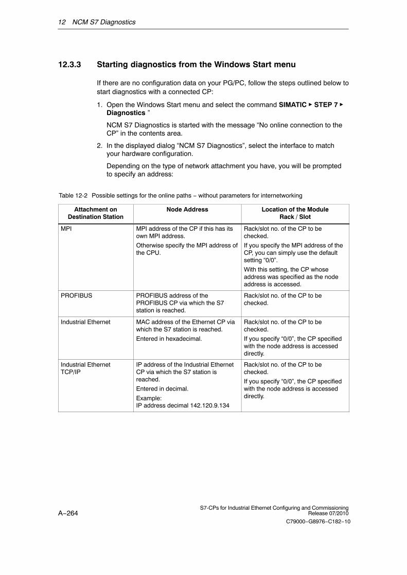
12 NCM S7 Diagnostics
A−264S7-CPs for Industrial Ethernet Configuring and Commissioning
Release 07/2010
C79000−G8976−C182−10
12.3.3 Starting diagnostics from the Windows Start menu
If there are no configuration data on your PG/PC, follow the steps outlined below tostart diagnostics with a connected CP:
1. Open the Windows Start menu and select the command SIMATIC � STEP 7 �Diagnostics ”
NCM S7 Diagnostics is started with the message “No online connection to theCP” in the contents area.
2. In the displayed dialog “NCM S7 Diagnostics”, select the interface to matchyour hardware configuration.
Depending on the type of network attachment you have, you will be promptedto specify an address:
Table 12-2 Possible settings for the online paths − without parameters for internetworking
Attachment onDestination Station
Node Address Location of the ModuleRack / Slot
MPI MPI address of the CP if this has itsown MPI address.
Otherwise specify the MPI address ofthe CPU.
Rack/slot no. of the CP to bechecked.
If you specify the MPI address of theCP, you can simply use the defaultsetting “0/0”.
With this setting, the CP whoseaddress was specified as the nodeaddress is accessed.
PROFIBUS PROFIBUS address of thePROFIBUS CP via which the S7station is reached.
Rack/slot no. of the CP to bechecked.
Industrial Ethernet MAC address of the Ethernet CP viawhich the S7 station is reached.
Entered in hexadecimal.
Rack/slot no. of the CP to bechecked.
If you specify “0/0”, the CP specifiedwith the node address is accesseddirectly.
Industrial EthernetTCP/IP
IP address of the Industrial EthernetCP via which the S7 station isreached.
Entered in decimal.
Example: IP address decimal 142.120.9.134
Rack/slot no. of the CP to bechecked.
If you specify “0/0”, the CP specifiedwith the node address is accesseddirectly.

12 NCM S7 Diagnostics
A−265S7-CPs for Industrial Ethernet Configuring and CommissioningRelease 07/2010
C79000−G8976−C182−10
Examples of an online path without gateway
Node address (MAC):08-00-06-01-02-03
Rack / slot : 0/4
Attachment of target sta-tion: Industrial Ethernet
S7 − 300CPU CP
PG/PC
Figure 12-1 CP requiring diagnostics can be reached directly
Node address (MAC):08-00-06-01-02-03
Rack / slot : 0/5
S7 − 300CPU CP
PG/PCCP
Network 2Attachment of target sta-tion: Industrial Ethernet
Figure 12-2 The CP requiring diagnostics is accessible indirectly over another CP

12 NCM S7 Diagnostics
A−266S7-CPs for Industrial Ethernet Configuring and Commissioning
Release 07/2010
C79000−G8976−C182−10
12.3.4 Using a gateway
Case a: One gateway
If the CP you want to check with diagnostic functions can only be reached via agateway, you must select the device and specify its node address in the localnetwork.
You must also specify the S7 subnet ID of the destination network:
The subnet ID consists of two numbers separated by a dash:
− One number for the project
− One number for the subnet
You will find the subnet ID in the object properties of the subnet in the STEP 7project. The subnet ID is also printed out with the network configuration.
Node address: PRO-FIBUS address 9
Rack / slot : 0/5
S7 − 300CPU CP
PG/PCCP
Attachment of gateway: Indu-strial Ethernet
S7 − 300CPU CP
Node address (gateway) (MAC):08-00-06-01-02-03
Attachment of target station: MPI/PROFIBUS/AUTO
S7 subnet ID of target network:0001−0001
Figure 12-3 Example of the parameter settings for the online path with one gateway
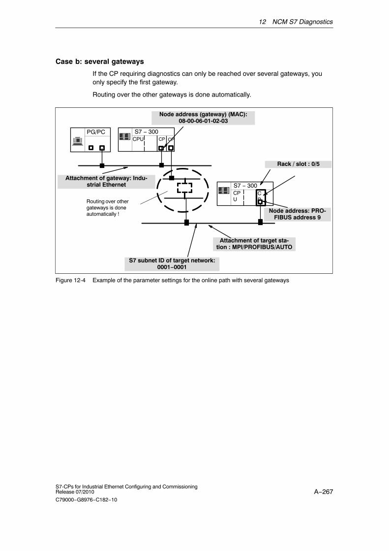
12 NCM S7 Diagnostics
A−267S7-CPs for Industrial Ethernet Configuring and CommissioningRelease 07/2010
C79000−G8976−C182−10
Case b: several gateways
If the CP requiring diagnostics can only be reached over several gateways, youonly specify the first gateway.
Routing over the other gateways is done automatically.
Node address: PRO-FIBUS address 9
Rack / slot : 0/5
S7 − 300CPU CP
PG/PCCP
Attachment of gateway: Indu-strial Ethernet S7 − 300
CPU
CP
Node address (gateway) (MAC):08-00-06-01-02-03
Attachment of target sta-tion : MPI/PROFIBUS/AUTO
S7 subnet ID of target network:0001−0001
Routing over other gateways is doneautomatically !
Figure 12-4 Example of the parameter settings for the online path with several gateways

12 NCM S7 Diagnostics
A−268S7-CPs for Industrial Ethernet Configuring and Commissioning
Release 07/2010
C79000−G8976−C182−10
Case c: IP subnet gateway via an Advanced CP with 2 interfaces
In the following case, the CP for which you want to run diagnostics is in a differentIP subnet from your PG/PC (but in the same S7 subnet). The IP subnet gateway ison an Advanced CP with 1 PROFINET interface and 1 gigabit interface.
PG/PC
S7 − 400
Ethernet CP
S7 − 300
Ethernet (1)(157.0.0.0)
Ethernet (2)
Advanced CP
Gigabit interface(157.55.80.1)
PROFINET interface
Figure 12-5 Example of a network gateway via an Advanced CP
In this case, the CP for which you want to run diagnostics cannot be reached if theinterface on your PG/PC is set to ISO. In this case, follow the steps below:
1. Set the interface of your PG/PC to TCP/IP.
2. For the network attachment of your PG/PC, enter the use of a default router inthe STEP 7 project.
3. For the address of the default router, enter the IP address of the interface of theAdvanced CP that can be reached in the local subnet (in the schematic157.55.80.1; see also Section 1.7.7).
4. Start NCM S7 Diagnostics from the Windows Start menu as described above.
The connection is established from the PG/PC to the target node via the twointerfaces of the Advanced CP.

12 NCM S7 Diagnostics
A−269S7-CPs for Industrial Ethernet Configuring and CommissioningRelease 07/2010
C79000−G8976−C182−10
12.3.5 Using a PC station − setting a gateway with ”PC internal”
There is a special situation when you use your PC/PG as a PC station and havetherefore set the interface to PC internal (local) in ”Setting the PG/PC Interface”.You must then set parameter values for the gateway, even when you do not needto go through any other gateway to reach the target station.
Select the following settings:
� Gateway attachment: MPI/PROFIBUS/AUTO
� Node address (gateway)
Enter the index of the module here.
The index is the virtual slot address of the component (can be displayed usingthe Station Configuration Editor). The index is identical to the slot numberselected during configuration of the PC station in STEP 7 HW Config!
� S7 subnet ID of destination network:
Follow the same steps as described for setting the gateway.
Tip:
You do not need to make these settings for the gateway if you select one of thefollowing options:
� Start NCM Diagnostics from the Properties dialog of the CP.
� When setting up your module, do not select the interface as PC internal (local)in ”Set PG/PC Interface”.
Node address: PROFIBUSaddress 12
Rack / slot : 0/4
Attachment of target sta-tion : MPI/PROFIBUS/AUTO
S7 − 300CPU CP
PC stationCPOPC
server
Gateway attachment: MPI/PROFI-BUS/AUTO
S7 subnet ID of target network:0001 0001
Node address (gateway) : 2 (here,the index of the module!)
Figure 12-6 Example of settings with “PC internal”

12 NCM S7 Diagnostics
A−270S7-CPs for Industrial Ethernet Configuring and Commissioning
Release 07/2010
C79000−G8976−C182−10
12.3.6 Other ways of starting diagnostics
Starting in the properties dialog of the connections:
1. Select the PLC�Activate Connection Status menu command to activateonline access.
2. Select the “Special Diagnostics” button in the “Status Information” tab.
Starting in the hardware configuration tool HW Config:
1. With the S7 station online, select the PLC�Module Status menu command;
2. Select the “Special Diagnostics” button in the dialog that is opened.
Note
To operate several diagnostic connections at the same time, you can start NCMS7 Diagnostics more than once.
You can also start NCM S7 Diagnostics twice with an online connection to thesame CP; this can, for example, be useful if you want to monitor the diagnosticbuffer at the same time as running diagnostic functions on a connection.
Requirement: You have an online connection available via the LAN (ISO orTCP/IP) on the one hand and an online connection via the communication (K) buson the other (alternatively via the CPU or via PG channel routing via a further CP).

12 NCM S7 Diagnostics
A−271S7-CPs for Industrial Ethernet Configuring and CommissioningRelease 07/2010
C79000−G8976−C182−10
12.4 How to use diagnostics
Procedure
To use diagnostics efficiently, particularly when working with the diagnostic tool forthe first time, the following procedure can be recommended.
1. Use the sequence shown below as a basis for using diagnostics:
Start NCM S7 Diagnostics: − Establish the connection to the CP (Section 12.3 − Set the options (Section 12.2.2)− Identify the Ethernet CP
Query the current status of the CP ”Operating Mode” diagnostic object
View / evaluate the diagnostic buffer to obtain an overview and detailed explanation of diagnostic events.
TCP connectionsISO transport connections/ISO-on-TCP connectionsUDP connections
If the CP is in the RUN mode
If necessary, correct configuration or programming.
If the CP is notin the RUN mode
If anything unusual isdisplayed for− connection status− receive status,− send status
2. Clarify your problem or task using the check list in Section 12.6 and select thediagnostic function based on the recommendation there.

12 NCM S7 Diagnostics
A−272S7-CPs for Industrial Ethernet Configuring and Commissioning
Release 07/2010
C79000−G8976−C182−10
12.5 Starting diagnostic functions explicitly
The following table shows the diagnostic options that exist in the availablefunctions.
Table 12-3 General diagnostic and statistical functions
Diagnosticfunctions /
diagnostic object
Diagnostic aims Special Features
CP information The aim is to identify the CP to whichNCM S7 Diagnostics is connected andto find out the current mode.
Mode Here, the aim is to find out the currentoperating mode of the Ethernet CP as amodule in the S7-300/400 and as a nodeon Industrial Ethernet and, if necessary,to modify the mode (menu commandOperating Mode�Stop Module / StartModule / Reset Memory / Reset toFactory Settings).
Diagnostic buffer General error diagnostics usingdiagnostic buffers
To display and decode event messagesrecorded on the CP in detail. Thediagnostic buffer provides you withdetailed information about all thecommunication services of the CP.
Event messages are recorded on the CPin a ring buffer. The ring buffer cancontain up to 50 entries.
In NCM S7, on the other hand, up to 500messages can be saved!
All the CP functions can generate eventmessages. When you call the diagnosticobject, the messages are read out anddisplayed. The latest message isdisplayed in the top line with the highestconsecutive number.
If you double-click a previously selectedevent message, you display a help textexplaining the message in greater detail.
Note
The event messages in the circulating buffer of the CP are lost after cycling thepower (on S7 CPs) or after booting (on PC stations).
If necessary, you have the option of logging in a file if you want to review thehistory of the event messages later.
You will find further information in the online help of the diagnostic object”Diagnostic buffer”

12 NCM S7 Diagnostics
A−273S7-CPs for Industrial Ethernet Configuring and CommissioningRelease 07/2010
C79000−G8976−C182−10
Table 12-4 Mode-dependent functions
Diagnosticfunctions /
diagnostic object
Diagnostic aims Special Features
To display and monitor communication connections. You obtain an overview or detailed information in thecontents area depending on the diagnostic object you select.
Connections � Overview of All Connection TypesUsed
By double-clicking the objects in thecontents area, you can display detailedinformation.
Connections �
Type� Overview of all the communication
connections of a particular type, forexample all TCP connections;
� Information on the connection status
Connections �
Type � Type-connection-n
� Detailed information about the statusof a communication connection.

12 NCM S7 Diagnostics
A−274S7-CPs for Industrial Ethernet Configuring and Commissioning
Release 07/2010
C79000−G8976−C182−10
12.6 Checklist for ‘typical problems‘ in a system
Meaning
The following lists contain several typical problems and their possible causes andhow you can use the NCM S7 Ethernet Diagnostics tool to remedy the situation.
The checklists deal with the following topics:
1. Checklist for general CP functions
2. Communication connection checklist
Note
In the column “Identifying the Cause and Remedy”, you will see the diagnosticfunction recommended for dealing with the problem shown in bold face.
12.6.1 Checklist for general CP functions
Table 12-5 Checklist for typical problems when operating a CP in a system
Problem Possible Cause Identifying the Cause and Remedy
The Ethernet CP will notchange to the RUN mode.
Invalid configurationloaded on the EthernetCP.
Yellow STOP LED and red SF LED litcontinuously.
Call up the diagnostic buffer in NCM S7Ethernet Diagnostics.
Example of an entry
CP STOP due to invalid CP parameterassignment
What to do:Correct the configuration of the Ethernet CP.
Switch set to STOP on theEthernet CP
(only CPs with RUN/STOPswitch)
Query the operating mode in NCM S7Diagnostics.
Operating mode: STOP, Cause: switch set toSTOP
What to do:Change the switch to RUN on the Ethernet CP

12 NCM S7 Diagnostics
A−275S7-CPs for Industrial Ethernet Configuring and CommissioningRelease 07/2010
C79000−G8976−C182−10
12.6.2 Communication connection checklist
Table 12-6 Checklist for typical problems with ISO transport / ISO-on-TCP / UDP connections
Problem Possible Cause Identifying the Cause and Remedy
No data transfer on anISO transport connection/ ISO-on-TCP connectionor only in one direction.
AG-SEND and AG-RECVare not called in the userprogram.
or
Receive or send buffer toosmall or incorrect.
Check the user program.
Evaluate status bytes in AG-SEND andAG-RECV.
What to do:
If necessary, configure FC blocks.
If necessary, correct ANY pointer.
The connection is notestablished.
Evaluate status bytes of the FC blocks orevaluate diagnostic buffer.
What to do:Change the address parameters (MAC/IPaddress, TSAP).
Data transfer too slow Receiving device too slow Evaluate diagnostic buffer.
Entry: “No receive resources on destinationstation XX”.
What to do:Delay the send trigger or check the destinationstation and optimize reception.
The complete data fieldis not sent on an ISOtransport /ISO-on-TCP/UDPconnection.
LEN parameter forAG-SEND is set to thewrong value.
What to do:Set the LEN parameter to the required size.
The complete data fieldis not sent on an ISOtransport /ISO-on-TCP/UDPconnection.
The buffer specified withthe ANY pointer is toosmall.
What to do:Correct the LEN parameter and the ANY pointer.
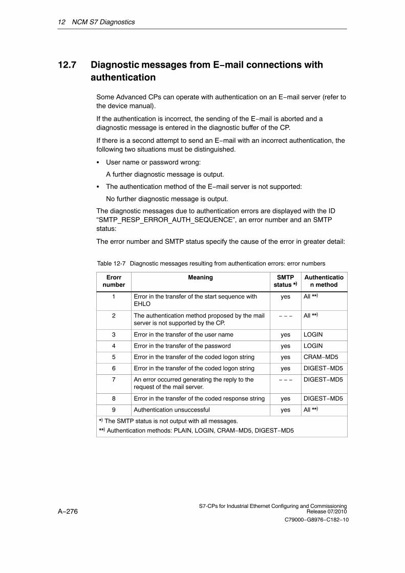
12 NCM S7 Diagnostics
A−276S7-CPs for Industrial Ethernet Configuring and Commissioning
Release 07/2010
C79000−G8976−C182−10
12.7 Diagnostic messages from E−mail connections withauthentication
Some Advanced CPs can operate with authentication on an E−mail server (refer tothe device manual).
If the authentication is incorrect, the sending of the E−mail is aborted and adiagnostic message is entered in the diagnostic buffer of the CP.
If there is a second attempt to send an E−mail with an incorrect authentication, thefollowing two situations must be distinguished.
� User name or password wrong:
A further diagnostic message is output.
� The authentication method of the E−mail server is not supported:
No further diagnostic message is output.
The diagnostic messages due to authentication errors are displayed with the ID“SMTP_RESP_ERROR_AUTH_SEQUENCE”, an error number and an SMTPstatus:
The error number and SMTP status specify the cause of the error in greater detail:
Table 12-7 Diagnostic messages resulting from authentication errors: error numbers
Erorrnumber
Meaning SMTPstatus *)
Authentication method
1 Error in the transfer of the start sequence withEHLO
yes All **)
2 The authentication method proposed by the mailserver is not supported by the CP.
− − − All **)
3 Error in the transfer of the user name yes LOGIN
4 Error in the transfer of the password yes LOGIN
5 Error in the transfer of the coded logon string yes CRAM−MD5
6 Error in the transfer of the coded logon string yes DIGEST−MD5
7 An error occurred generating the reply to therequest of the mail server.
− − − DIGEST−MD5
8 Error in the transfer of the coded response string yes DIGEST−MD5
9 Authentication unsuccessful yes All **)
*) The SMTP status is not output with all messages.
**) Authentication methods: PLAIN, LOGIN, CRAM−MD5, DIGEST−MD5

12 NCM S7 Diagnostics
A−277S7-CPs for Industrial Ethernet Configuring and CommissioningRelease 07/2010
C79000−G8976−C182−10
Table 12-8 Diagnostic messages resulting from authentication errors: SMTP status
SMTPstatus
Meaning
1xx The mail server has accepted the request but is itself not yet active. Aconfirmation message is required.
2xx Mail server executed request without error.
3xx The mail server understood the request but requires further information forprocessing.
4xx Mail server has detected a temporary error. If the request is repeated withoutbeing modified, processing may possibly be completed.
5xx Mail server has detected a fatal error. The request cannot be processed.
�

A−278S7-CPs for Industrial Ethernet Configuring and Commissioning
Release 07/2010
C79000−G8976−C182−10
13 Firmware Loader
This chapter will familiarize you with the uses and handling of the FirmwareLoader.
The firmware loader allows you to download more recent firmware versions to theSIMATIC NET modules.
13.1 Area of application
Firmware
Here, firmware means the system programs in the SIMATIC NET modules.
Uses of the Firmware Loader
The firmware loader allows you to download more recent firmware versions to theSIMATIC NET modules. It is used on the following:
� PROFIBUS modules
� Industrial Ethernet modules
� Modules for gateways (for example, IE/PB Link)
Installation
The firmware loader is available when you have installed NCM S7 on your PG/PC.
Load files
The firmware loader supports the following file types:
� <file>.FWL
A file form that contains extra information that can be displayed in the dialogs ofthe firmware loader in addition to the actual firmware. Based on thisinformation, the firmware loader can check the firmware for compatibility withthe device.
For detailed information, read the documentation, for example, the README fileshipped with the load file.
This information is displayed even after reading in the FWL file into the firmwareloader.
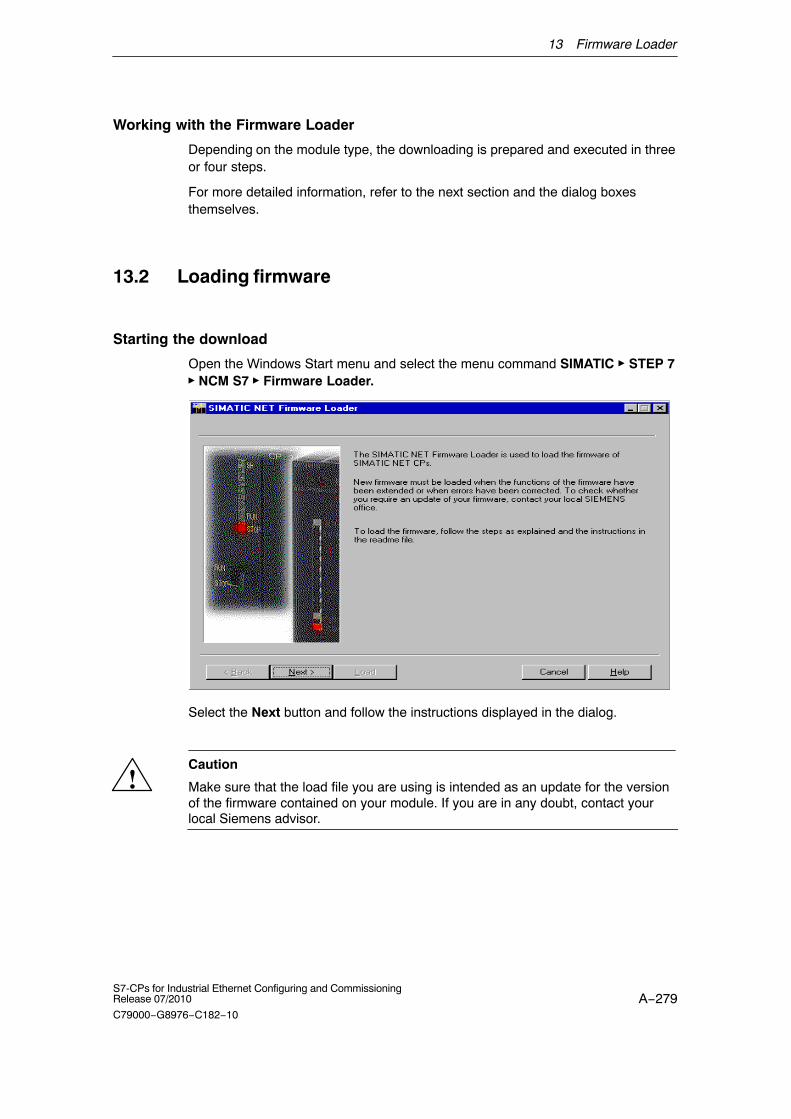
13 Firmware Loader
A−279S7-CPs for Industrial Ethernet Configuring and CommissioningRelease 07/2010
C79000−G8976−C182−10
Working with the Firmware Loader
Depending on the module type, the downloading is prepared and executed in threeor four steps.
For more detailed information, refer to the next section and the dialog boxesthemselves.
13.2 Loading firmware
Starting the download
Open the Windows Start menu and select the menu command SIMATIC � STEP 7� NCM S7 � Firmware Loader.
Select the Next button and follow the instructions displayed in the dialog.
!Caution
Make sure that the load file you are using is intended as an update for the versionof the firmware contained on your module. If you are in any doubt, contact yourlocal Siemens advisor.

13 Firmware Loader
A−280S7-CPs for Industrial Ethernet Configuring and Commissioning
Release 07/2010
C79000−G8976−C182−10
!Caution
Remember that interrupting the download can lead to an inconsistent state on themodule!
For more information, read the description of the relevant device in Part B of thismanual.
For more detailed information on the various load options, refer to the integratedhelp.
�

A Connector Pinning
A−281S7-CPs for Industrial Ethernet Configuring and CommissioningRelease 07/2010
C79000−G8976−C182−10
A Connector Pinning
A.1 24 V DC connector
Terminal Function
L+ +24 V
M Ground
A.2 RJ-45 jack for twisted−pair Ethernet
CPs with One Connector
Pin no. Signal name Function
1 TD TP− / Transmit +
2 TD_N TP− / Transmit −
3 RD TP− / Receive +
4 − −
5 − −
6 RD_N TP− / Receive −
7 − −
8 − −
The pinning of the RJ-45 jack corresponds to the IEEE802.3 twisted pair interface.
Multiport switch of the PROFINET interface
Pin no. Signal name Function
1 RD TP− / Receive +
2 RD_N TP− / Receive −
3 TD TP− / Transmit +
4 − −
5 − −
6 TD_N TP− / Transmit −
7 − −
8 − −
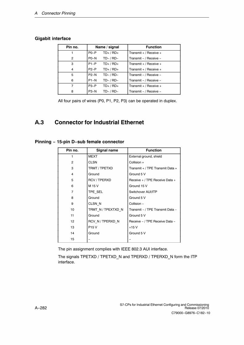
A Connector Pinning
A−282S7-CPs for Industrial Ethernet Configuring and Commissioning
Release 07/2010
C79000−G8976−C182−10
Gigabit interface
Pin no. Name / signal Function
1 P0−P TD+ / RD+ Transmit + / Receive +
2 P0−N TD− / RD− Transmit − / Receive −
3 P1−P TD+ / RD+ Transmit + / Receive +
4 P2−P TD+ / RD+ Transmit + / Receive +
5 P2−N TD− / RD− Transmit − / Receive −
6 P1−N TD− / RD− Transmit − / Receive −
7 P3−P TD+ / RD+ Transmit + / Receive +
8 P3−N TD− / RD− Transmit − / Receive −
All four pairs of wires (P0, P1, P2, P3) can be operated in duplex.
A.3 Connector for Industrial Ethernet
Pinning − 15-pin D−sub female connector
Pin no. Signal name Function
1 MEXT External ground, shield
2 CLSN Collision +
3 TRMT / TPETXD Transmit + / TPE Transmit Data +
4 Ground Ground 5 V
5 RCV / TPERXD Receive + / TPE Receive Data +
6 M 15 V Ground 15 V
7 TPE_SEL Switchover AUI/ITP
8 Ground Ground 5 V
9 CLSN_N Collision −
10 TRMT_N / TPEXTXD_N Transmit − / TPE Transmit Data −
11 Ground Ground 5 V
12 RCV_N / TPERXD_N Receive − / TPE Receive Data −
13 P15 V +15 V
14 Ground Ground 5 V
15 − −
The pin assignment complies with IEEE 802.3 AUI interface.
The signals TPETXD / TPETXD_N and TPERXD / TPERXD_N form the ITPinterface.

A Connector Pinning
A−283S7-CPs for Industrial Ethernet Configuring and CommissioningRelease 07/2010
C79000−G8976−C182−10
A.4 Connector for PROFIBUS
9-pin D-sub female connector for PROFIBUS (used with IE/PB Link)
Pin no. Signal name PROFIBUSname
Used withRS-485
1 PE Protective earth yes
2 − − −
3 RxD/TxD−P Data line B yes
4 RTS (AG) Control A −
5 M5V2 Data referencepotential
yes
6 P5V2 Power supplyplus
yes
7 BATT − −
8 RxD/TxD−N Data line A yes
9 − − −

B Standards and approvals of SIMATIC NET S7 CPs
A−284S7-CPs for Industrial Ethernet Configuring and Commissioning
Release 07/2010
C79000−G8976−C182−10
B Standards and approvals of SIMATIC NETS7 CPs
The approvals listed in this chapter apply to the following modules.
Notice
You will find the valid approvals on the type plate of the relevant product.
Product description:
� CP 343−1 Lean Order no.: 6GK7 343−1CX00−0XE0
� CP 343−1 Lean Order no.: 6GK7 343−1CX10−0XE0
� CP 343−1 Order no.: 6GK7 343−1EX11−0XE0
� CP 343−1 Order no.: 6GK7 343−1EX20−0XE0
� CP 343−1 Order no.: 6GK7 343−1EX21−0XE0
� CP 343−1 Order no.: 6GK7 343−1EX30−0XE0
� CP 343−1 IT Order no.: 6GK7 343−1GX20−0XE0
� CP 343−1 PN Order no.: 6GK7 343−1HX00−0XE0
� CP 343−1 Advanced Order no.: 6GK7 343−1GX21−0XE0
� CP 343−1 Advanced Order no.: 6GK7 343−1GX30−0XE0 *)
� CP 443−1 Order no.: 6GK7 443−1EX11−0XE0
� CP 443−1 Order no.: 6GK7 443−1EX20−0XE0
� CP 443−1 IT Order no.: 6GK7 443−1GX11−0XE0
� CP 443−1 Advanced Order no.: 6GK7 443−1EX40−0XE0
� CP 443−1 Advanced Order no.: 6GK7 443−1EX41−0XE0
� CP 443−1 Advanced Order no.: 6GK7 443−1GX20−0XE0 *)
� IE/PB Link Order no.: 6GK1411−5AA00
� IE/PB Link PN IO Order no.: 6GK1411−5AB00
� IWLAN/PB Link PN IO Order no.: 6GK1417−5AB00
*) New modules included in the manual release.
Note
You will find the valid approvals on the type plate of the relevant product.

B Standards and approvals of SIMATIC NET S7 CPs
A−285S7-CPs for Industrial Ethernet Configuring and CommissioningRelease 07/2010
C79000−G8976−C182−10
IEC 61131–2
The SIMATIC NET S7−CPs listed above meet the requirements and criteria of thestandard IEC 61131–2 (Programmable Logic Controllers, Part 2: EquipmentRequirements and Tests).
CE mark
The SIMATIC NET S7 CPs listed above meet the requirements and aims of thefollowing EU directives and comply with the harmonized European standards (EN)for programmable logic controllers published in the Official Journal of the EuropeanCommunities:
� 2004/108/EEC “Electromagnetic Compatibility“ (EMC directive)
� 94/9/EEC ”Equipment and Protective Systems for Use in Potentially ExplosiveAtmospheres” (explosion protection directive)
The EU conformity certificates are available for the responsible authoritiesaccording to the above-mentioned EU directive at the following address:
� Siemens AktiengesellschaftIndustry AutomationIndustrielle Kommunikation SIMATIC NET Postfach 4848D−90327 NürnbergGermany
The EC Declaration of Conformity is also available on the Internet at the followingaddress:
� http://support.automation.siemens.com/WW/view/en/16689636
EMC directive
The SIMATIC NET S7−CPs listed above are designed for use in an industrialenvironment.
Area of Application Requirements
Noise emission Noise immunity
Industrial EN 61000–6–4 : 2007 EN 61000–6–2 : 2005
Explosion protection directive
Complying with EN 60079 (Electrical apparatus for potentially explosiveatmospheres; Type of protection „n“)
EN 60079−15:2005, EN 60079−0:2006
II 3 G Ex nA II T3...T6
KEMA 07 ATEX 0145X

B Standards and approvals of SIMATIC NET S7 CPs
A−286S7-CPs for Industrial Ethernet Configuring and Commissioning
Release 07/2010
C79000−G8976−C182−10
KEMA 03 ATEX 1229X
KEMA 03 ATEX 1228X
KEMA 03 ATEX 1125X
Note
When using (installing) SIMATIC NET products in hazardous area zone 2, makeabsolutely sure that the associated conditions are adhered to!
You will find these conditions here:
� In the SIMATIC NET Manual Collection under
All Documents > “Approval of SIMATIC/SIMATIC NET Products for DirectInstallation in Ex−Zone 2”
You will find details of the SIMATIC products here:
� On the Internet at the address
http://support.automation.siemens.com/WW/view/en/13702947
Machinery directive
The product remains a component in compliance with Article 4(2) of the ECMachinery Directive 98/37/EEC.
According to the directive on machines, we are obliged to point out that thisproduct is intended solely for installation in a machine. Before the final product isstarted up, it must be established that it conforms to the directive 98/37/EEC.
Installation guidelines
The product meets the requirement if you adhere to the installation and safetyinstructions contained in this device manual and in the documentation /3/ and /4/.
!Warning
Personal injury and damage to property may occur.
By installing expansions that are not approved for SIMATIC S7 CPs or their targetsystems, the requirements and regulations regarding safety and electromagneticcompatibility may be violated.
Only use expansions approved for the system.
Notice for Australia
The SIMATIC NET S7 CPs listed above meet the requirements of the AS/NZS2064 standard (Class A).

B Standards and approvals of SIMATIC NET S7 CPs
A−287S7-CPs for Industrial Ethernet Configuring and CommissioningRelease 07/2010
C79000−G8976−C182−10
Notice for Canada
This class A digital device meets the requirements of the Canadian ICES-003standard.
AVIS CANADIEN
Cet appareil numérique de la classe A est conforme à la norme NMB-003 duCanada.
UL and CSA approval
Note
You can recognize which of the following UL/CSA or cULus approvals apply toyour product by the markings on the type plate.
UL approval
UL Recognition Mark Underwriters Laboratories (UL) according to standard UL508:
� Report E 85972
CSA approval
CSA Certification Mark Canadian Standard Association (CSA) according tostandard C 22.2 No.142
� Certification Record 063533–C−000

B Standards and approvals of SIMATIC NET S7 CPs
A−288S7-CPs for Industrial Ethernet Configuring and Commissioning
Release 07/2010
C79000−G8976−C182−10
cULus approval, Hazardous Location
CULUS Listed 7RA9 IND. CONT. EQ. FOR HAZ. LOC.
Underwriters Laboratories Inc. according to
� UL 508 (Industrial Control Equipment)
� CSA C22.2 No. 142 (Process Control Equipment)
� ANSI ISA 12.12.01, CSA C22.2 No. 213−M1987
� CSA–213 (Hazardous Location)
APPROVED for Use in
� Cl. 1, Div. 2, GP. A, B, C, D T4A
� Cl. 1, Zone 2, GP. IIC T3...T6
� Cl. 1, Zone 2, AEx nC IIC T3...T6
Refer to the type plate on the module for the temperature class.
!Warning
Explosion Hazard −
Do not disconnect while circuit is live unless area is known to be non hazardous.
!Warning
Explosion Hazard −
Substitution of components may impair suitability for Class I, Division 2.
Note
This equipment is suitable for use in Class I, Division 2, Group A, B, C, D ornon-hazardous locations only.
Notice
For devices with C-PLUG memory: The C-PLUG memory module may only beinserted or removed when the power is off.
Note the following information:

B Standards and approvals of SIMATIC NET S7 CPs
A−289S7-CPs for Industrial Ethernet Configuring and CommissioningRelease 07/2010
C79000−G8976−C182−10
Note
The system must be set up according to the regulations of the NEC (NationalElectrical Code).
When used in environments corresponding to Class I, Division 2 (see above), theSIMATIC NET S7 CPs must be installed in an enclosure.
FM approval
Factory Mutual Approval Standard Class Number 3611, Class I, Division 2, Group A, B, C, D, T3...T6 or Class I, Zone 2, Group IIC, T3...T6.
Refer to the type plate on the module for the temperature class.
!Warning
Personal injury and damage to property may occur.
In hazardous areas, personal injury or damage to property may occur if you makeor break an electrical circuit while a SIMATIC NET S7−CP is in operation (forexample, plug−in connectors, fuses, switches).
WARNING − EXPLOSION HAZARD: DO NOT DISCONNECT EQUIPMENTWHEN A FLAMMABLE OR COMBUSTIBLE ATMOSPHERE IS PRESENT.
When used in hazardous areas (division 2 or zone 2), the device must be installedin an enclosure.
C−TICK
AS/NZS 2064 (Class A)
A−290S7-CPs for Industrial Ethernet Configuring and Commissioning
Release 07/2010
C79000−G8976−C182−10
C References and Literature
Locating Siemens literature
The order numbers for Siemens documentation can be found in the catalogs”SIMATIC NET Industrial Communication, catalog IK PI” and ”SIMATIC Productsfor Totally Integrated Automation and Micro Automation, catalog ST 70”.
You can obtain these catalogs and any further information you require from yourlocal SIEMENS office or national head office.
Some of the documents listed here are also in the SIMATIC NET ManualCollection supplied with every S7-CP.
Many SIMATIC NET manuals are available on the Internet pages of SiemensCustomer Support for Automation:
http://support.automation.siemens.com/WW/view/de
Enter the ID of the relevant manual as a search key. The ID is shown below theliterature name in brackets.
Manuals that are installed with the online documentation of the STEP 7 installationon your PG/PC, can be selected from the Start menu (Start > SIMATIC >Documentation).
You fill find a overview of the SIMATIC documentation at:
http://www.automation.siemens.com/simatic/portal/html_76/techdoku.htm
On configuration, commissioning and use of the CP
SIMATIC NETS7 CPs for Industrial Ethernet − device documentation Part BManualSiemens AG(manual for each CP in the SIMATIC NET Manual Collection)
SIMATIC NETVersion history / current downloads for SIMATIC NET S7 CPsSiemens AG(SIMATIC NET Manual Collection)
http://support.automation.siemens.com/WW/view/en/9836605
/1/
/2/

C References and Literature
A−291S7-CPs for Industrial Ethernet Configuring and CommissioningRelease 07/2010
C79000−G8976−C182−10
On configuration with STEP 7 / NCM S7
SIMATIC NETNCM S7 for Industrial EthernetPrimerSiemens AGPart of the online documentation in STEP 7
SIMATIC NETS7 CPs for Industrial Ethernet − device documentation Part AConfiguration and CommissioningConfiguration manualSiemens AGPart of the online documentation in STEP 7
http://support.automation.siemens.com/WW/view/en/30374198
SIMATIC NETCommissioning PC Stations − Manual and Quick StartConfiguration manualSiemens AG(SIMATIC NET Manual Collection)
http://support.automation.siemens.com/WW/view/en/13542666
SIMATICConfiguring Hardware and Connections with STEP 7 Part of the STEP 7 documentation package STEP 7 Basic Knowledge”Part of the online documentation of STEP 7Siemens AG
SIMATICPROFINET System DescriptionSystem manualSiemens AG
http://support.automation.siemens.com/WW/view/en/19292127
On project engineering of PROFINET CBA (components and systems):
Component based Automation − Configuring Plants with SIMATIC iMapManual Siemens AG(ID: 18404678)
http://support.automation.siemens.com/WW/view/en/18404678
/3/
/4/
/5/
/6/
/7/
/8/

C References and Literature
A−292S7-CPs for Industrial Ethernet Configuring and Commissioning
Release 07/2010
C79000−G8976−C182−10
Basic Help in the SIMATIC iMap Engineering Tool (online help)Siemens AG
You will find further information on SIMATIC iMAP at:
http://support.automation.siemens.com/WW/view/en/10805413
On programming
SIMATIC NETFunctions (FC) and Function Blocks (FBs) for SIMATIC NET S7 CPsProgramming ManualSiemens AG(SIMATIC NET Manual Collection)(ID: 30564821)
http://support.automation.siemens.com/WW/view/en/30564821
Version history of the SIMATIC NET function blocks and functions for SIMATIC S7Reference workSiemens AG(SIMATIC NET Manual Collection)(ID: 9836605)
http://support.automation.siemens.com/WW/view/en/9836605
SIMATIC − Programming with STEP 7Part of the STEP 7 documentation package STEP 7 Basic KnowledgePart of the online documentation of STEP 7Siemens AG
Automatisieren mit STEP 7 in AWL und SCL (ISBN: 978−3−89578−280−0) /Automating with STEP 7 in STL and SCL (ISBN: 978−3−89578−295−4)User manual, programming manualBerger, HansPublicis KommunikationsAgentur GmbH, GWA, 2006
For installation and commissioning of the CP
SIMATIC S7S7−300 Automation System− CPU 31xC und 31x Installation: Operating Instructions (ID: 13008499)− Module Data: Reference Manual (ID: 8859629)Siemens AG
http://support.automation.siemens.com/WW/view/en/13008499
http://support.automation.siemens.com/WW/view/en/8859629
/9/
/10/
/11/
/12/
/13/
/14/

C References and Literature
A−293S7-CPs for Industrial Ethernet Configuring and CommissioningRelease 07/2010
C79000−G8976−C182−10
and
SIMATIC S7SIMATIC S7S7−400, M7−400 Automation system− Installation Manual (ID: 1117849)− Module Data: Reference Manual (ID: 1117740)Siemens AG
http://support.automation.siemens.com/WW/view/en/1117849
http://support.automation.siemens.com/WW/view/en/1117740
On using and configuring PROFINET IO
SIMATICPROFINET System DescriptionSystem Manual Siemens AG(Part of the Manual Collection)
SIMATICFrom PROFIBUS DP to PROFINET IOProgramming ManualSiemens AG(Part of the Manual Collection)
On the IT functions of the CPs
Creating Java Beans with IBM VisualAgeSIEMENS AG(ID: 10499820)
http://support.automation.siemens.com/WW/view/en/10499820
S7Beans / Applets for IT−CPsProgramming AidSIEMENS AG(SIMATIC NET Manual Collection)(ID: 24843908)
http://support.automation.siemens.com/WW/view/en/24843908
/15/
/16/
/17/
/18/

C References and Literature
A−294S7-CPs for Industrial Ethernet Configuring and Commissioning
Release 07/2010
C79000−G8976−C182−10
On setting up and operating an Industrial Ethernet network
SIMATIC NETManual Twisted Pair and Fiber−Optic NetworksSiemens AG(SIMATIC NET Manual Collection)
SIMATIC NETManual Triaxial Networks(SIMATIC NET Manual Collection)
SIMATIC and STEP 7 basics
Communication with SIMATICSystem Manual Siemens AG(ID: 25074283)
http://support.automation.siemens.com/WW/view/en/25074283
Documentation package “STEP 7 Basic Knowledge”with− Working with STEP 7 V5.4 Getting Started (ID: 18652511)− Programming with STEP 7 (ID: 18652056)− Configuring Hardware and
Communication Connections with STEP 7(ID: 18652631)− Form S5 to S7, Converter Manual (ID: 1118413)Siemens AGOrder number 6ES7 810−4CA08−8AW0Part of the online documentation in STEP 7
Documentation package “STEP 7 Reference”with − Statement List (STL) for S7−300/400 (ID: 18653496)− Ladder Diagram (LAD) for S7−300/400 (ID: 18654395)− Function Block Diagram (FBD) for S7−300/400 (ID: 18652644)− System and Standard Functions for S7−300/400 Volumes 1 and 2 (ID: 1214574)− System software for S7-300/400 System and Standard Functions Part 2Siemens AGOrder number 6ES7 810−4CA08−8AW1Part of the online documentation in STEP 7
Other topics
Ethernet, IEEE 802.3 (ISO 8802−3)(http://www.ieee.org)
/19/
/20/
/21/
/22/
/23/
/24/

C References and Literature
A−295S7-CPs for Industrial Ethernet Configuring and CommissioningRelease 07/2010
C79000−G8976−C182−10
RFC1006 (ISO Transport Service on top of the TCP Version: 3)Request For Comment(http://www.ietf.org)
RFC793 (TCP)(http://www.ietf.org)
RFC791 (IP)(http://www.ietf.org)
/25/
/26/
/27/

A−296S7-CPs for Industrial Ethernet Configuring and Commissioning
Release 07/2010
C79000−G8976−C182−10
D Glossary
D.1 General Section A−296. . . . . . . . . . . . . . . . . . . . . . . . . . . . . . . . . . . . . . . . . . . . . .
D.2 Industrial Ethernet and IT functions of the CPs A−300. . . . . . . . . . . . . . . . . . .
D.3 PROFINET A−305. . . . . . . . . . . . . . . . . . . . . . . . . . . . . . . . . . . . . . . . . . . . . . . . . .
D.1 General section
BroadcastA broadcast is like “calling all stations”: Using one broadcast frame, you canreach all nodes that are prepared to accept broadcast frames.
Bus segmentPart of a −> subnet. Subnets can consist of bus segments and connectivitydevices such as repeaters and bridges. Segments are transparent foraddressing.
ClientA client is a device or, in general terms, an object that requests a service from a−> server.
Configuration dataParameters that determine the modes and functions of a −> CP. They are setand downloaded using the NCM S7 configuration tool.
CPCommunications Processor. Module for communications tasks.
CSMA/CDCSMA/CD (Carrier Sense Multiple Access with Collision Detection); atransmission technique.
FrameA message from one PROFIBUS/Ethernet station/node to another.
Frame headerA frame header consists of an identifier for the −> frame and the source anddestination address.

D Glossary
A−297S7-CPs for Industrial Ethernet Configuring and CommissioningRelease 07/2010
C79000−G8976−C182−10
Frame trailerA frame trailer consists of a checksum and the end identifier of the −> frame.
Functions (FCs)STEP 7 code blocks of the type “function”.
GatewayIntelligent connectivity device that connects local area −> networks of differenttypes at the ISO Layer 7 level.
Industrial EthernetA LAN system complying with IEEE 802.3 (ISO 8802−2)
MulticastA multicast is like “calling all group stations”: Using one multicast frame, you canreach all the nodes that belong to the multicast group and that are prepared toreceive frames.
NCM S7 for Industrial EthernetConfiguration software for configuration and diagnostic functions on an EthernetCP.
NCM S7 for PROFIBUSConfiguration software for configuration and diagnostic functions on aPROFIBUS CP.
NetworkA network consists of one or more interconnected −> subnets with any numberof −> nodes. Several networks can exist side by side.
OPOperator panel, HMI device
PC stationPC station means a PC with communications modules and applications. This PCis intended, for example, to communicate with SIMATIC S7 devices duringprocess control tasks. These PCs equipped with runtime software are alsoknown as runtime stations.The PC station is configured in SIMATIC NCM PC / STEP 7 for communicationwith SIMATIC S7 devices.The required runtime software is available on the PC station after APC(Advanced PC Configuration) is installed.

D Glossary
A−298S7-CPs for Industrial Ethernet Configuring and Commissioning
Release 07/2010
C79000−G8976−C182−10
PG operationA mode of the PROFIBUS/Ethernet CP in which the SIMATIC S7−CPU isprogrammed, configured or diagnosed via PROFIBUS/Ethernet. This mode ishandled using S7 functions.
PROFInetStandard of the PROFIBUS Users organization defining a heterogeneouscommunications and engineering model.
ProtocolA set of rules for transferring data. Using these rules, both the formats of theframes and the data flow are specified.
Process imageThe process image is a special memory area in the programmable logiccontroller. At the start of the cyclic program, the signal states of the inputmodules are transferred to the process input image. At the end of the cyclicprogram, the process output image is transferred as a signal state to the outputmodules.
SegmentSynonym for −> Bus segment.
ServerA server is a device, or in general terms, an object that provides certain services.A service is started at the instigation of a −> client.
ServicesServices provided by a communication protocol.
SIMATIC NETSiemens SIMATIC Network and Communication. Product name for −> networksand network components from Siemens. (previously SINEC)
SIMATIC NET Industrial EthernetSIMATIC NET LAN system for industrial applications based on Ethernet.(previously SINEC H1)
SIMATIC NCM PCSIMATIC NCM PC allows STEP 7-compatible configuration for SIMATIC NETPC components and replaces the previous PC configuration tools COML S7 andCOM PROFIBUS PC Edition. By sharing a common database with STEP 7, fullyintegrated configuration including all protocols is ensured.

D Glossary
A−299S7-CPs for Industrial Ethernet Configuring and CommissioningRelease 07/2010
C79000−G8976−C182−10
SINECPrevious product name for −> networks and network components from Siemens.Now: SIMATIC NET
Station
A station is identified by a
� MAC address in the Ethernet network
� PROFIBUS address in the PROFIBUS network
Subnet
A subnet is part of a −> network whose parameters (for example −> PROFIBUS)must be matched. The subnet includes bus components and all the attachedstations. Subnets can, for example, be connected together by −> gateways toform a network.
A −> system consists of several subnets with unique −> subnet numbers. Asubnet consists of several −> stations with unique −> PROFIBUS or MACaddresses (Industrial Ethernet).
You will find detailed information in the online help of STEP 7.
SystemThis means all the electrical equipment within a system. A system includes,among other things, programmable logic controllers, devices for operation andmonitoring, bus systems, field devices, actuators, supply lines.
Transport layerThe transport layer is layer 4 of the ISO/OSI reference model for open systeminterconnection. The purpose of the transport layer is to transfer data reliablyfrom device to device. Transport connections can be used for the transmission.
TSAPTransport Service Access Point
Transmission rateAccording to DIN 44302, this is the number of binary decisions transmitted pertime unit. The unit is bps. he set or selected transmission rate depends onvarious conditions, for example the distance across the network.
WatchdogMechanism for monitoring operability or a function.

D Glossary
A−300S7-CPs for Industrial Ethernet Configuring and Commissioning
Release 07/2010
C79000−G8976−C182−10
D.2 Industrial Ethernet and IT functions of the CPs
APIApplication Programming Interface: programming library.
Applet−> Java applet
Bean−> JavaBean
Base address
Logical address of a module in S7 systems.
� For PROFIBUS
The PROFIBUS base address is the address starting at which all addressesthat are calculated automatically in the project are assigned.
� For Industrial Ethernet
The base MAC address is the address starting at which all addresses that arecalculated automatically in the project are assigned.
E−mail connectionAn E−mail connection is a logical connection between an S7 CPU and an IT−CP.It is essential for sending E−mails.
ESMTPExtended Simple Mail Transfer Protocol: Extended protocol of the Internetprotocol family for transferring E−mails, based on −> SMTP.
FTPFile Transfer Protocol
HTMLHyper Text Markup Language is the name of an intermediate file format that isunderstood by all Web browsers and makes data communication easier.
HTML process controlName of the technique allowing process information to be accessed using HTMLpages.
D Glossary
A−301S7-CPs for Industrial Ethernet Configuring and CommissioningRelease 07/2010
C79000−G8976−C182−10
HTML pageA file created in HTML format that can be made available, for example on Webservers and can be called in the intranet/Internet.
HTTPHyper Text Transfer Protocol
HTML tagHTML tags are structure elements of HTML documents. These structureelements include, for example, titles, paragraphs, tables and even applet calls.
IDEIntegrated Development Environment, for example, eclipse, Borland JBuilder etc.
ISO−on−TCP
Transport layer connection (layer 4 communication complying with ISO)simulated on TCP.
On an ISO-on-TCP connection, messages can be exchanged in both directions.TCP provides the data flow communication without segmenting the data intomessages. ISO, on the other hand, is message-oriented. With ISO-on-TCP, thismechanism is simulated on TCP. This is described in RFC1006 (Request ForComment).
ISO-on-TCP connections allow program/event-controlled communication viaEthernet from a SIMATIC S7 PLC to
� SIMATIC S7 PLC with Ethernet CP
� SIMATIC S5 PLC with Ethernet CP
� PC/PG with Ethernet CP
� any system

D Glossary
A−302S7-CPs for Industrial Ethernet Configuring and Commissioning
Release 07/2010
C79000−G8976−C182−10
ISO transport connection
Communication connection of the transport layer (with the CP/COM 143previously S5S5 connection).
ISO transport connections allow program/event-controlled communication onIndustrial Ethernet between SIMATIC S7 PLCs and
� SIMATIC S7 PLC with Ethernet CP
� SIMATIC S5 with an Ethernet CP (e.g. CP 143 or CP 1430)
� PC/PG with Ethernet CP (for example CP 1613)
� Any system using the ISO transport protocol (ISO 8073)
The transfer of blocks of data on an ISO transport connection is bi-directional.
IT-CPThe abbreviation “IT−CP” stands for CP modules with E−mail−, FTP or Webfunctions (for example CP x43−1 Advanced or CP x43−1 IT).
JavaObject−oriented programming language developed by Sun Microsystems
Java appletsThese are small Java applications that are transferred from Web servers toclients where they are run (in a Web browser with Java capability).
JavaBeanA JavaBean (or simply “bean”) is a reusable software object with a standardizedinterface that can be linked with other JavaBeans in Builder tools to create anapplication (for example a Java applet). Ready−to−use S7 beans are availablefor IT−CP.
JavaScriptA script language developed by Netscape. JavaScript allows Web documents tobe designed interactively and dynamically. JavaScript is a programminglanguage that is easy to learn.
Java Virtual Machine (JVM)−> SUN Java Virtual Machine (JVM)
MAC addressAddress to distinguish between different stations connected to a commontransmission medium (Industrial Ethernet).

D Glossary
A−303S7-CPs for Industrial Ethernet Configuring and CommissioningRelease 07/2010
C79000−G8976−C182−10
Media Access Control (MAC)Mechanisms for controlling access by a station to a common transmissionmedium shared with other stations.
Proxy serverA proxy server can increase the security in a network. The software can be used,for example, to check access or to deny access to particular pages ordocuments as is also the case with a firewall. A proxy server can also serve as atype of buffer so that web pages that have been called once do not always haveto be addressed again via the host. This allows wait times to be reducedconsiderably.
RFC1006Request for Comment nr. 1006. Document of the Internet Engineering TaskForce (IETF) for specification of the ISO transport service on TCP.See also −> ISO−on−TCP
S5 connectionsee ISO transport connection
S7 appletsS7 applets are special Java applets that allow read and write access to an S7station via the CP IT.
S7 beansS7 beans are special JavaBeans supplied for the IT−CP in a class library. Theyallow access to process data via IT−CP and display of the data in a Webbrowser.
S7 subnet IDYou will find detailed information in the online help of STEP 7.
S7BeansAPIThe S7BeansAPI is a software component library. It contains the S7 beans of theIT−CP.
SMTPSimple Mail Transfer Protocol: Protocol of the Internet protocol family fortransferring E−mails.
Subnet maskYou will find detailed information in the online help of STEP 7.

D Glossary
A−304S7-CPs for Industrial Ethernet Configuring and Commissioning
Release 07/2010
C79000−G8976−C182−10
SUN Java Virtual Machine (JVM)The Java Virtual Machine is the central element in SUN’s Java programmingenvironment. This component makes Java programs independent of a particularplatform.
TCP/IPTCP = Transport Connection Protocol; IP = Internet Protocol
Industrial Ethernet nodeA station is identified by a −> MAC address in −> Industrial Ethernet.
UDPUser Datagram Protocol. User Datagram Protocol: datagram service for simpleinternetwork transmission without acknowledgment.
URL (Uniform Resource Locator)Identifies the address of a document in an intranet or on the Internet.
Web browserBasic software for presenting multimedia offers on the World Wide Web (Web orWWW) on a PG/PC
Web serverTerm for a computer in the network that provides services to other computers inthe Web at the request of a client (−> Web browser).

D Glossary
A−305S7-CPs for Industrial Ethernet Configuring and CommissioningRelease 07/2010
C79000−G8976−C182−10
D.3 PROFINET
Component based AutomationConcept for implementing modular, distributed automation applications on thebasis of open standards and data communication.Component based Automation is an expansion of Totally Integrated Automation(TIA).
DeviceIN PROFINET CBA: Part of the PROFINET component that contains thehardware-specific data of the PROFINET component. In SIMATIC iMap, a deviceis the software representation of the physical device for which the PROFINETcomponent was created. It is displayed in the network view of SIMATIC iMap asan object with one or more bus attachments. The following distinction is madeaccording to the communication functionality: −> PROFINET devices and −>PROFIBUS devices.
InterconnectionGeneral: Logical data connection between two objects.In PROFINET CBA in SIMATIC iMap: Connection between two technologicalfunctions. An output is interconnected with an input of the same type.Interconnections are represented in SIMATIC iMap by lines.
Network viewIn PROFINET CBA: View of the devices and the networks (Ethernet,PROFIBUS) in SIMATIC iMap.
Plant viewIn PROFINET CBA: View of the technological functions of the automationsystem and its interconnections in SIMATIC iMap. One chart is displayed in theplant view.
PROFIBUS deviceIn PROFINET CBA: A PROFIBUS device has only one PROFIBUS attachmentas a slave. It does not take part directly in PROFINET communication but islinked using a proxy PROFINET device.

D Glossary
A−306S7-CPs for Industrial Ethernet Configuring and Commissioning
Release 07/2010
C79000−G8976−C182−10
PROFINETWithin the framework of Totally Integrated Automation (TIA), PROFINET is theconsistent continuation of:− PROFIBUS DP, the established fieldbus, and− Industrial Ethernet, the communications bus for the cell level.The experience gained in both systems was and is integrated in PROFINET.PROFINET as an Ethernet-based automation standard from PROFIBUSInternational (previously PROFIBUS Users Organization e.V.) defines aheterogeneous communication, automation and engineering model.
PROFINET deviceIn PROFINET CBA: A device on Ethernet is a PROFINET device. A PROFINETdevice can also have a PROFIBUS attachment as master and proxy PROFINETdevice for PROFIBUS devices.
PROFINET device, proxyA PROFINETt device that has the role of the master for PROFIBUS devices.This allows PROFIBUS slaves to be included in PROFINET communication.
PROFINET IOHeterogeneous communication and engineering model for real-timecommunication between PROFINET components. PROFINET IO, for example,provides protocol elements for cyclic transfer of productive data.
PROFINET componentIn PROFINET CBA: Software view of a technological module with definedfunctionality. An automation system is made up of several PROFINETcomponents.A PROFINET component always includes a technological function and thecorresponding device.
SIMATIC iMapEngineering tool from Siemens for PROFINET CBA. Allows the configuration,commissioning, and monitoring of modular, distributed automation systemsbased on the PROFINET standard.
SIMATIC iMap − STEP 7 Add−onSoftware for the SIMATIC iMap interface to STEP 7.
�

A−307S7-CPs for Industrial Ethernet Configuring and CommissioningRelease 07/2010
C79000−G8976−C182−10
E Linking to Other Systems with FETCH/WRITE
The FETCH and WRITE modes supported on ISO transport connections, TCP,and ISO-on-TCP connections can be used with any other device to access the S7system memory areas.
To be able to use this type of access, for example for PC applications, you need toknow the PDU structure of the jobs. The required S7 or S5 header for request andresponse frames are 16 bytes long and their structure is described in this chapter.
a) Structure of WRITE frames
The meaning and values of parameters shown without values in the following tablecan be found in the section “Parameter values“.
WRITE request frame WRITE acknowledgment frame
0 System ID =”S” 0 System ID =”S”
1 =”5” 1 =”5”
2 Length of header =0x10 2 Length of header =0x10
3 ID OP code =0x01 3 ID OP code =0x01
4 Length OP code =0x03 4 Length OP code =0x03
5 OP code =0x03 5 OP code =0x04
6 ORG field =0x03 6 Ack field =0x0F
7 Length ORG field =0x08 7 Length ack field =0x03
8 ORG ID 8 Error field =No
9 DBNR 9 Empty field =0xFF
A Start address High Byte A Length empty field =0x07
B Low Byte B
C Length High Byte C
D Low Byte D free
E Empty field =0xFF. E
F Length empty field =0x02 F
Data up to 64 K

E Linking to Other Systems with FETCH/WRITE
A−308S7-CPs for Industrial Ethernet Configuring and Commissioning
Release 07/2010
C79000−G8976−C182−10
b) Structure of FETCH frames
The meaning and values of parameters shown without values in the following tablecan be found in the section “Parameter values“.
FETCH request frame FETCH response frame
0 System ID =”S” 0 System ID =”S”
1 =”5” 1 =”5”
2 Length of header =0x10 2 Length of header =0x10
3 ID OP code =0x01 3 ID OP code =0x01
4 Length OP code =0x03 4 Length OP code =0x03
5 OP code =0x05 5 OP code =0x06
6 ORG field =0x03 6 Ack field =0x0F
7 Length ORG field =0x08 7 Length ack field =0x03
8 ORG ID 8 Error field =No
9 DBNR 9 Empty field =0xFF
A Start address High Byte A Length empty field =0x07
B Low Byte B
C Length High Byte C
D Low Byte D free
E Empty field =0xFF E
F Length empty field =0x02 F
Data up to 64 K butonly if Error no. =0

E Linking to Other Systems with FETCH/WRITE
A−309S7-CPs for Industrial Ethernet Configuring and CommissioningRelease 07/2010
C79000−G8976−C182−10
Parameter values
S7 Address Area DB M I Q
ORG ID 01H 02H 03H 04H
Source/dest.data from/todata block inmain memory
Source/dest.data from/tobit memoryarea
Source/dest.data from/toprocessimage of theinputs (PII)
Source/dest.data from/toprocessimage of theoutputs (PIQ)
DBNR DB, fromwhich thesource dataare taken or towhich the destdata aretransferred
irrelevant irrelevant irrelevant
permitted range 1...255
Start address DW number,from whichthe data aretaken orwritten to
Memory byteno., fromwhich thedata are takenor written to
Input byte no.,from whichthe data aretaken orwritten to
Output byteno., fromwhich thedata are takenor written to
permitted range 0...2047 All memorybytes madeavailable by aCPU.
0...127 0...127
Length Length of thesource/dest.data field inwords
Length of thesource/dest.data field inbytes
Length of thesource/dest.data field inbytes
Length of thesource/dest.data field inbytes
permitted range Up to 8192bytes
Up to 8192bytes
1...128 1...128

E Linking to Other Systems with FETCH/WRITE
A−310S7-CPs for Industrial Ethernet Configuring and Commissioning
Release 07/2010
C79000−G8976−C182−10
S7
Address AreaPI/PQ C T
ORG ID 05H 06H 07H
Source/dest.data from/to inI/O modules.With sourcedata inputmodules, withdest dataoutput modules
Source/destdata from/tocounter cells
Source/destdata from/totimer cells
DBNR irrelevant irrelevant irrelevant
Start address I/O byte no.,from which thedata are takenor written to
Number of thecounter cellfrom which thedata are takenor written to
Number of thetimer cell fromwhich the dataare taken orwritten to
permitted range 0...127
digital I/Os128...255
Analog I/O
0...255 0...255
Length Length of thesource/dest.data field inbytes
Length of thesource/dest.data field inwords (countercell = 1 word)
Length of thesource/dest.data field inwords (countercell = 1 word)
permitted range 1...256 1 1
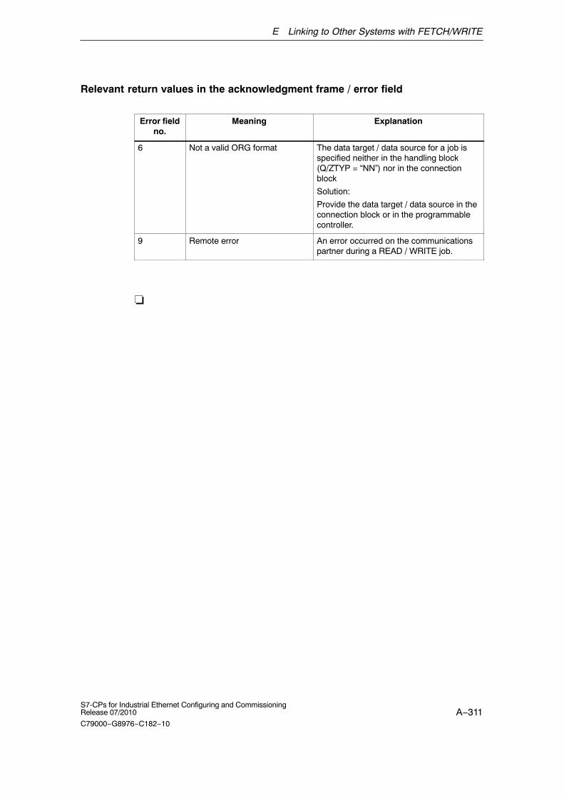
E Linking to Other Systems with FETCH/WRITE
A−311S7-CPs for Industrial Ethernet Configuring and CommissioningRelease 07/2010
C79000−G8976−C182−10
Relevant return values in the acknowledgment frame / error field
Error fieldno.
Meaning Explanation
6 Not a valid ORG format The data target / data source for a job isspecified neither in the handling block(Q/ZTYP = “NN”) nor in the connectionblock
Solution:
Provide the data target / data source in theconnection block or in the programmablecontroller.
9 Remote error An error occurred on the communicationspartner during a READ / WRITE job.
�
A−312S7-CPs for Industrial Ethernet Configuring and Commissioning
Release 07/2010
C79000−G8976−C182−10
F Document History
This section provides an overview of the previous releases of this manual and thefunctional expansions in STEP 7 and NCM S7.
This was new in release 09 / STEP 7 V5.4 SP4 (C79000−G8976−C182−09)
The manuals for the S7−Cps for Industrial Ethernet were restructured:
� The “Information Technology in SIMATIC S7 with CPs for S7−300 and S7−400”was integrated in the manual.
� Removal and summary of the block descriptions in the new manual “Functions(FCs) and Function blocks (FBs) for SIMATIC NET S7−CPs − ProgrammingManual (/10/)”.
� The paper version of the manuals will no longer be printed.
Technical Innovations
Apart from various adaptations to the currently shippable devices and the currentversion of STEP 7 / NCM S7 V5.4 SP4, the following changes were made:
� Parameter modifications to the blocks for PROFINET IO (see /10/):
− FC11 PNIO_SEND (block version 2.0)
− FC12 PNIO_RECV (block version 2.0)
The two functions must be used in version V2.0 if you want the CP to operate inPROFINET IO controller and device mode at the same time.
� New function block FB40 for FTP client mode of Advanced−CPs (in /10/)
� Expansion of the SMTP protocol to ESMTP for authentication of an AdvancedCP as E−mail client with a mail server (function: Chapter 8; diagnosticmessages: section 12.7)
� Description of the Web diagnostics with new diagnostic functions
� New functions in the CP 343−1GX30−0XE0, CP 443−1EX20−0XE0 (firmwareversion 2.0) and CP 443−1GX20−0XE0: module access protection, UDPbuffering
F Document History
A−313S7-CPs for Industrial Ethernet Configuring and CommissioningRelease 07/2010
C79000−G8976−C182−10
� New functions in the CP 343−1GX30−0XE0 and CP 443−1GX20−0XE0:upper/lower case for file names in the file system
This was new in release 08 / STEP 7 V5.4 SP3 (C79000−G8976−C182−08)
Apart from various adaptations to the currently supplied devices and the currentversion of STEP 7/NCM S7 V5.4 SP3, the following features were included:
� Additional information in the block description
New blocks for user programs (only S7−400 / CP 443−1):
− FC53 AG_SSEND
− FC63 AG_SRECV
With CPs of the S7-400, that support PROFINET communication in conjunctionwith CPUs as of version 5.1, data can be transmitted at a higher transmissionrate using the FCs AG_SSEND and AG_SRECV.
Note
Note that the IT functions (E−mail, FTP, Web functions) of theCP 343−1 Advanced (EX41) and the CP 443−1 Advanced (GX20) were describedin the following manual:
”Information Technology in SIMATIC S7 with CPs for S7−300 and S7−400”
This manual is no longer in print. The IT functions are now described in thismanual (as of release 09). The new manual structure is described in the Preface.
This was new in release 07 / STEP 7 V5.4 SP2 (C79000−G8976−C182−07)
Apart from various adaptations to the currently available devices, the followingtopics are also included:
� Configuration of the CP mode PROFINET IO device or controller
Certain CP 343−1 device types can be operated in the PROFINET IO controlleror PROFINET IO device modes.
� Additional information in the block description
New blocks for user programs of the CP 343−1 in the PROFINET IO controllermode:
− FB52 PNIO_RW_REC
− FB54 PNIO_ALARM
� Introduction of Web diagnostics for the new CP 343−1 types
This was new in release 06 / STEP 7 V5.4 SP1 (C79000−G8976−C182−06)
Apart from various adaptations to the currently supplied devices and the current
F Document History
A−314S7-CPs for Industrial Ethernet Configuring and Commissioning
Release 07/2010
C79000−G8976−C182−10
version of STEP 7/NCM S7 V5.4 SP1, the following features were included:
� Configuration of the CP mode PROFINET IO device
Depending on the device type, certain CPs can be configured and operated inthe PROFINET IO controller or PROFINET IO device modes.
� Corrections and additions to the block description
Corrections and additions were made to the following FCs/FBs.
− FC11 PNIO_SEND
− FC12 PNIO_RECV
These FCs are now also used for the PROFINET IO device mode of theCP 343−1 Lean.
This was new in release 05 / STEP 7 V5.4 SP2 (C79000−G8976−C182−05)
Apart from various adaptations to the currently supplied devices and the currentversion of STEP 7/NCM S7 V5.4, the following features were included:
� New blocks for user programs
− A new block FB90 PN_InOut_Fast is available for PROFINET CBA(previous name: PN_IO_X).
� Corrections and additions to the block description
Corrections and additions were made to the following FCs/FBs.
− FB88 PN_InOut / FB90 PN_InOut_Fast
− FB55 IP_CONFIG
− FC11 PNIO_SEND
− FC12 PNIO_RECV
This was new in release 04 / STEP 7 V5.3 SP3 (C79000−G8976−C182−04)
Apart from various adaptations to the currently supplied devices and the currentversion of STEP 7/NCM S7 V5.3 SP2/SP3, the following features were included:
� New blocks for user programs
− A new block FB90 PN_IO_X is available for PROFINET CBA.
This was new in release 03 / STEP 7 V5.3 SP3 (C79000−G8976−C182−03)
Apart from various adaptations to the currently supplied devices and the currentversion of STEP 7/NCM S7 V5.3 SP2/SP3, the following features were included:
� New blocks for user programs
− There is a new block FC10 AG_CNTRL available for the SEND/RECEIVEinterface
− There are also detailed sample programs for the SEND/RECEIVE interface

F Document History
A−315S7-CPs for Industrial Ethernet Configuring and CommissioningRelease 07/2010
C79000−G8976−C182−10
on the Web. You will find the useful link in Chapter 7 of release 03.
� Expanded sample of programmed communication connections.
� Printed version − General Part A and Device Description Part B separate
Due to the increasing size, the printed version has been divided into twovolumes.
This was new in release 02 / STEP 7 V5.3 SP2 (C79000−G8976−C182−02)
� New blocks for user programs
New FCs and FBs are available for PROFINET services. Descriptions that weretemporarily included in new releases of the specific device manuals are nowincluded in this general part.
� Range of devices described: S7 CPs and gateways
The devices described in detail in Part B now include not only the CPs forSIMATIC S7 but also the gateway IWLAN/PB Link PN IO. This step was takenin particular due to the special significance for PROFINET applications.
This was new in release 01 / STEP 7 V5.3 SP0 (C79000−G8976−C182−01)
� New structure of the manual
In this release we have put together the previously separate manuals NCM S7and S7 CPs in one manual.
This also takes into account that the NCM S7 configuration tool is no longerinstalled separately for PROFIBUS and Industrial Ethernet. The functions ofNCM S7 are now installed automatically when STEP 7 is installed.
� Range of devices described: S7 CPs and gateways
The devices described in detail in Part B now include not only the CPs forSIMATIC S7 but also the gateway IE/PB Link. This step was taken in particulardue to the special significance for PROFINET applications.
This was new in release 07 / STEP 7 V5.2 SP1 (C79000−G8976−C129−07)
Note
This is the last release before the two manuals “NCM S7 for Ind. Ethernet” and“Device Manual S7-CPs for Ind. Ethernet” were merged.
This manual also includes specially marked passages that apply specifically to andrequire version 5.2 SP1 of the NCM S7for Industrial Ethernet configurationsoftware and version 5.2 SP1 of the STEP 7 software.

F Document History
A−316S7-CPs for Industrial Ethernet Configuring and Commissioning
Release 07/2010
C79000−G8976−C182−10
These include new functions for IP configuration:
� IP Access Protection
Using IP access protection gives you the opportunity of restricting access to thelocal S7 station to partners with specific IP addresses.
� Configuring connections from the user program
In some situations, it is an advantage to set up communication connections notover the configuration interface of STEP 7 but program-controlled by specificapplications.
As of STEP 7 V5.2 SP1, a function block is available for these applications thatallows flexible transfer of data blocks with configuration data to an Ethernet CP.
The description of the configuration for FETCH / WRITE services has beenextended.
This was new in release 06 / STEP 7 V5.2 SP2 (C79000−G8976−C129−06)
� S7 communication over routers (single-ended client and server functionality) viaan IE/PB Link or CP.
� Multiprojects
With the new multiproject functionality, projects can be split up and distributedfor engineering and then merged again.
This was new in release 05 / STEP 7 V5.1 SP3 (C79000−G8976−C129−05)
� Configuring multicast and broadcast on UDP connections.
� The blocks AG_SEND and AG_RECV can now be used for “long data packets”with an S7−300. See Chapter 7 of release 05.
� The S7 CPs for Ind. Ethernet are now supplied with a default MAC addressallowing configuration data to be downloaded over Ethernet without a ”nodeinitialization”.
This was new in release 04 / up to STEP 7 V5.1 SP2 (C79000−G8976−C129−04)
� The FETCH/WRITE mode is now supported on TCP connections.
� The FETCH/WRITE mode can be coordinated in the user program by the newFCs AG_LOCK and AG_UNLOCK. See Chapter 7 of release 04.
� NCM Diagnostics has a completely revised user interface.
The description of NCM S7 Diagnostics has been restructured. While thismanual provides you with an overview and checklists, the online help providesyou with detailed information on the diagnostic events.

A−317S7-CPs for Industrial Ethernet Configuring and CommissioningRelease 07/2010
C79000−G8976−C182−10
AAccess protection: IT_Webserver A−235Access rights, FTP: IT_FTP_ohne_FCs
A−208Access rights for IT CPs, configuring:
Inbetrieb A−83Activating Web server functionality: Web−Diag
A−239Address parameters
broadcast: verb A−162multicast: verb A−163unspecified ISO−on−TCP connection: verb
A−144unspecified TCP connection: verb A−152unspecified UDP connection: verb A−159
Advanced CP, resources: IT_WebserverA−230
ApprovalC−TICK: ce A−289CSA: ce A−287FM: ce A−289IEC 61131−2: ce A−285UL: ce A−287
Authentication on mail server: IT_E−MailA−194
BBroadcast, with UDP: verb A−160
CC−TICK, Approval: ce A−289CE Mark: ce A−285Commissioning: Inbetrieb A−61Communication
IT: einstieg A−24PG/OP: einstieg A−24PROFINET: einstieg A−24S5-compatible: einstieg A−24S7: einstieg A−24
Communications processors; designfor S7-300: CP_Merkmale A−53for S7-400: CP_Merkmale A−54
ConfigurationE−mail connection: IT_E−Mail A−197FTP connections: IT_FTP_ohne_FCs
A−223mail server address: IT_E−Mail A−193PROFINET IO device: PNIO−Device
A−181Configuration data, downloading to target
system: Inbetrieb A−103Configuring IT functions: Inbetrieb A−83Connection, properties: verb A−120Connection configuration: verb A−118Connection endpoint, E−mail connection:
IT_E−Mail A−197Connection resources, S7-300: CP_Merkmale
A−57Connector pinning
15-pin D−sub female connector: steckerA−282
RJ-45 jack: stecker A−281CP project engineering data, saving: Inbetrieb
A−104Creating a subnet: Inbetrieb A−64CSA, approval: ce A−287CSMA/CD: einstieg A−20
DData block, E−mail DB: IT_E−Mail A−199DHCP server: Inbetrieb A−80Diagnostic buffer
querying: IT_Webserver A−235setting the language: IT_Webserver A−236
Disabling the ISO protocol: Inbetrieb A−104Displaying network attachments: Inbetrieb
A−69DNS (Domain Name System): Inbetrieb A−83Download, sample projects/programs:
sendrecv A−106Downloading HTML pages, : IT_Webserver
A−238Downloading the configuration: Inbetrieb
A−103Dynamic properties, for ISO transport: verb
A−136

A−318S7-CPs for Industrial Ethernet Configuring and Commissioning
Release 07/2010
C79000−G8976−C182−10
EE−mail, testing: IT_E−Mail A−202E−mail client: IT_E−Mail A−193E−mail connection, configuring: IT_E−Mail
A−195, A−197E−mail DB: IT_E−Mail A−199E-mail
attachments: IT_E−Mail A−201data length: IT_E−Mail A−201
Ethernet, overview: einstieg A−20Ethernet CP
commissioning, steps: Inbetrieb A−63further CP properties: Inbetrieb A−71
FFB 40 for FTP: IT_FTP_ohne_FCs A−228FC 40...44 for FTP: IT_FTP_ohne_FCs A−228FC 5 / 50 / 53,
AG_SEND/AG_LSEND/AG_SSEND:sendrecv A−107E−mail: IT_E−Mail A−199
FC 6 / 60 / 63,AG_RECV/AG_LRECV/AG_SRECV:sendrecv A−107
FETCH/WRITE servicesconfiguration for ISO transport: verb A−168overview: einstieg A−39
File access with FTP: IT_FTP_ohne_FCsA−208
File allocation table: IT_FTP_ohne_FCsA−213
File DB: IT_FTP_ohne_FCs A−218header: IT_FTP_ohne_FCs A−220structure: IT_FTP_ohne_FCs A−225
File management: IT_FTP_ohne_FCs A−206File system: IT_Webserver A−237File system inthe Advanced CP:
IT_Webserver A−235File system on the IT CP: IT_FTP_ohne_FCs
A−206Firewall: IT_Webserver A−231Firmware loader: FWLADER A−278FM, approval: ce A−289FTP blocks: IT_FTP_ohne_FCs A−228FTP client function: IT_FTP_ohne_FCs A−205FTP commands: IT_FTP_ohne_FCs A−211FTP connections: IT_FTP_ohne_FCs A−223FTP server functionality: IT_FTP_ohne_FCs
A−205
FTP tools, file access: IT_FTP_ohne_FCsA−208
Functions (FC), typical sequence: sendrecvA−110
Functions (FCs)PNIO_RECV: PNIO−Device A−192PNIO_SEND: PNIO−Device A−191
HHardware configuration, Ethernet CP:
Inbetrieb A−66HTML system pages: IT_Webserver A−235HTTP: IT_Webserver A−233
IIndustrial Ethernet, overview: einstieg A−20Industrial Ethernet; user interface to: einstieg
A−31Installation guidelines: ce A−286Intranet, CP access via: IT_Webserver A−233IP access control list (IP−ACL): Inbetrieb A−77IP address: IT_E−Mail A−199
configuring in the properties dialog:Inbetrieb A−80
mail server: IT_E−Mail A−197obtaining from a DHCP server: Inbetrieb
A−80setting in the user program: Inbetrieb A−80
IP configuration: Inbetrieb A−80IRT configuration
IO controller: PNIO−Controller A−174IO device: PNIO−Device A−182Limits of the sync domain: PNIO−Controller
A−175ISO transport connection: verb A−130, A−136
amount of data and number of connections:verb A−120
checking: verb A−138connection without assignment: verb
A−127printing configured connections: verb
A−126properties dialog: verb A−130
addresses: verb A−134general: verb A−131overview: verb A−138
save connection: verb A−126Unspecified connection: verb A−135

A−319S7-CPs for Industrial Ethernet Configuring and CommissioningRelease 07/2010
C79000−G8976−C182−10
ISO−on−TCP connectionaddresses: verb A−142checking: verb A−145properties: verb A−139specifying the connection partner: verb
A−140
JJava Development Kit: IT_Webserver A−233
LLAD/FBD/STL editor, for E−mail DB data:
IT_E−Mail A−199Loading firmware: FWLADER A−279
MMAC address: Inbetrieb A−104Mail server: IT_E−Mail A−197
configuring address: verb A−125;IT_E−Mail A−196
mode: IT_E−Mail A−196Module replacement
S7-300: CP_Merkmale A−57S7-400: CP_Merkmale A−59
MS DOS prompt: IT_FTP_ohne_FCs A−209Multicast, with UDP: verb A−160Multicomputing
S7-300: CP_Merkmale A−56S7-400: CP_Merkmale A−58
Multiproject: einstieg A−40, A−45configuring connections: verb A−119,
A−123
NNCM S7
general information: Inbetrieb A−62installation: Inbetrieb A−62
NCM S7 Diagnostics: NCM−Diag A−256for test mail: IT_E−Mail A−202
NCM S7 diagnosticsexamples of on online path with ”PC
internal”: NCM−Diag A−269overview: NCM−Diag A−257
NCM S7 Diagnostics online pathexamples of an online path with gateway:
NCM−Diag A−266examples of an online path without
gateway: NCM−Diag A−265Network access: einstieg A−20New connection: verb A−122NTP mode, time−of−day synchronization:
Inbetrieb A−77
OOpening ports, PC/PG/proxy: IT_Webserver
A−231Operator interface devices: einstieg A−30,
A−31Order numbers: ce A−284Original Advanced CP file system:
IT_FTP_ohne_FCs A−207Other station: einstieg A−40; verb A−123
configuring: Inbetrieb A−95connecting a subnet: Inbetrieb A−96
PPassword, FTP: IT_FTP_ohne_FCs A−208Password protection, IT CPs: Inbetrieb A−83PC internal: NCM−Diag A−269PG communication
in configured mode: einstieg A−29in PG operation: einstieg A−29with STEP 7 on PROFIBUS: einstieg A−29
PG operation, with STEP 7 via Ethernet:einstieg A−27
PG/PC interface: einstieg A−31Pin assignment, 15-pin D-sub female
connector: stecker A−283Private IP addresses, forwarding by Advanced
CP: einstieg A−52PROFIBUS; user interface to: einstieg A−31PROFINET communication: einstieg A−21,
A−22Programmed communication connections:
einstieg A−26
A−320S7-CPs for Industrial Ethernet Configuring and Commissioning
Release 07/2010
C79000−G8976−C182−10
Project variant1 subnet − 1 project: einstieg A−421 subnet − multiple projects: einstieg A−45Connections across subnets: einstieg A−50Multiple subnets − 1 project: einstieg A−44Multiple subnets − multiple subprojects:
einstieg A−48SIMATIC S5 and non−SIMATIC devices:
einstieg A−43Two subnets via Advanced CP: einstieg
A−51Proxy server, FTP: IT_Webserver A−231,
A−234
Rreadme.htm, file system, IT CPs:
IT_FTP_ohne_FCs A−207Routing to distribute load, connections: verb
A−171
SS7 applets: IT_Webserver A−238S7 communication on Ethernet: einstieg A−31S7 communication over Ethernet: einstieg
A−21S7 communication relay: einstieg A−31S7 connections
S7-300: CP_Merkmale A−57S7-400: CP_Merkmale A−59
Sample configuration, download: sendrecvA−106
Sample program, download: sendrecv A−106SEND/RECEIVE interface: einstieg A−21;
IT_E−Mail A−193CPU cycle: sendrecv A−112data exchange: sendrecv A−107overview: einstieg A−36user program: sendrecv A−109
SIMATIC mode, time−of−day synchronization:Inbetrieb A−77
SIMATIC NET, concept: einstieg A−20Simultaneous operation
of CPs; S7-300: CP_Merkmale A−56of CPs; S7-400: CP_Merkmale A−58
SlotsS7-300: CP_Merkmale A−56S7-400: CP_Merkmale A−58
STEP 7, Version: historie A−312SUN Java Virtual Machine: IT_Webserver
A−233System memory, access using
FETCH/WRITE: verb A−169
TTCP Connection, checking properties: verb
A−153TCP connection: verb A−146
addresses: verb A−149specifying the connection partner: verb
A−147Test mail: IT_E−Mail A−202Time-of-day synchronization: Inbetrieb A−73,
A−76Types of communication: einstieg A−21
UUDP
addresses: verb A−156checking: verb A−166configuring: verb A−154
UDP connection, specifying the connectionpartner: verb A−155
UL, approval: ce A−287Uniform Resource Locator : IT_Webserver
A−234Unspecified connection: verb A−124
S7 connection: verb A−124Users, access rights: Inbetrieb A−83
WWeb browser: IT_Webserver A−233
requirements profile: IT_Webserver A−233Web server start page, Advanced CP:
IT_Webserver A−235