S172E - Packscan IQ Field Unit Technical Manual
38
Pakscan IQ Field Unit Technical Manual Publication - S172E Issue 0.1 21 June 1994
-
Upload
wilmer-quishpe-andrade -
Category
Documents
-
view
36 -
download
4
description
Rotork IQ
Transcript of S172E - Packscan IQ Field Unit Technical Manual

IQ Field Unit Technical Manual - Publication S172E Issue 0.1
1 of 38
Pakscan IQ Field Unit Technical Manual
Publication - S172E Issue 0.1 21 June 1994

IQ Field Unit Technical Manual - Publication S172E Issue 0.1
2 of 38
As we are continually developing our products their design is subject to change without notice. The contents of this document are copyright and must not be reproduced without the written permission of Rotork Controls Ltd.
The information in this manual relates to IQ field control unit software version 1.04.
C

IQ Field Unit Technical Manual - Publication S172E Issue 0.1
3 of 38
Contents: 1 Introduction 2 Field Unit Properties 2.1 Mechanical Properties 2.2 Electrical Properties 2.3 Operation and Storage 3 Compatibility 3.1 Pakscan IIE Master Station 3.2 Pakscan II Master Station 3.3 Paktester 3.4 2 wire loop 4 Fitting the Field Unit 4.1 Remote Input Board 4.2 Replacing or Fitting a Field Unit 4.3 Fitting a Remote Input Board 5 2 wire loop Connections 6 2 wire loop interface 6.1 Loopback Feature 6.2 Loop Bypass Circuit 7 Input and Output Signals 7.1 Digital Status Data Bits 7.2 Alarm Status Data Bits 7.3 Additional Feedback Data 7.4 Command Outputs 8 Alarm Handling 9 Setting Up a Field Unit 9.1 Using a Paktester 9.2 Using a Setting Tool 9.3 Using a Communicator 10 Maintenance and Repair 11 Records Appendix 1 Parameter Access Table Appendix 2 Actuator Wiring Diagrams

IQ Field Unit Technical Manual - Publication S172E Issue 0.1
4 of 38
1. INTRODUCTION The Pakscan Field Unit fitted to the IQ actuator is fully compatible with Pakscan IIE 2 wire control systems and Pakvision 5. The IQ field unit forms an integral part of the IQ actuator and is housed within the main double sealed electrical housing of the actuator. The electrical housing need never be opened once the actuator leaves the assembly plant. All adjustments to the settings for the field unit may be made via the 2 wire interface using a Paktester or via the Infra-red link using the actuator setting tools. The field unit circuits do not impinge on the actuator control electronics, the actuator itself remains fully self protecting. The field unit performs the tasks of 2 wire interface communication, actuator data collection and the issuing of actuator commands.
���� �
���������
Motor
HandwheelElectricalCompartment
Terminal Cover Local Controls
fig 1: The IQ Actuator

IQ Field Unit Technical Manual - Publication S172E Issue 0.1
5 of 38
2. FIELD UNIT PROPERTIES
2.1 Mechanical Properties The field unit comprises a single printed circuit board that fits inside the actuator electrical housing. It connects to the main board of the actuator by a multipin connector and due to its physical shape the field unit may only be fitted in the correct polarisation. The actuator internal wiring harness has connections to the field unit for the two wire loop connection via the actuator terminal bung, the isolated supply voltages for the field unit and the remote auxiliary inputs. These connectors are polarised to prevent incorrect connection. The field unit connects either directly to the main pcb or indirectly through the Data Logging module when the Data Logger option is fitted to the actuator. 2.2 Electrical Properties The field unit processor circuits connect directly to the main processors of the actuator. The field unit does not sit in the main control path for the actuator and does not affect the actuator control integrity. The field unit processor is controlled by a programme stored in EPROM. The EPROM is located on the field unit board and marked as shown on the diagram. The software version is indicated on the label fitted to the EPROM. Additionally the circuit includes a non-volatile EEPROM that is used to store parameter settings that contain information about the field unit settings. The 2 wire loop interface electronics is also on the field unit board. The interface circuits are fully opto-isolated from the field unit processor and actuator electronics. The loop interface includes the loopback circuits used to maintain communication integrity if there is a loop cable fault and also the loop bypass circuits that ensure loop continuity if the actuator loses power.
P xxx
Main Connector
EPROM Processor Ground test point
Init test point
fig 2: The IQ field unit

IQ Field Unit Technical Manual - Publication S172E Issue 0.1
6 of 38
2.3 Operation and Storage The field unit is designed to be stored in the actuator and operated within the same environment as the actuator. The constraints are: Operating temperature: -40oC to +70oC Storage temperature: -50oC to +85o C Relative Humidity: 5% to 95% (<50oC) non-condensing

IQ Field Unit Technical Manual - Publication S172E Issue 0.1
7 of 38
3. COMPATIBILITY The IQ field unit is compatible with Pakscan IIE and Pakscan II master stations. Where the actuator is to be fitted as an extension to an already existing system there may be a need to upgrade the software fitted in the master station itself. 3.1 Pakscan IIE Master Station In order to fully support the IQ those systems fitted with master station V25 card software 5206-014 version 2.4 or lower and/or Loop Driver card software 5206-034 version 2.1 will require upgrade to a newer version when an IQ actuator is connected to the loop. 3.2 Pakscan II Master Station Those systems fitted with software 5146-052 version 2.1 or lower will require upgrade to a newer version to support the IQ on the loop. If the software is not upgraded then the IQ may cause loop communication failure. 3.3 Paktester In order to be able to use a Paktester to set up and commission the IQ actuator a Paktester fitted with software 5161-013 with a version higher than V4.0 must be used. The Rotork Communicator can also be used to set the IQ field unit parameters. Most, though not all, settings can be made using the Rotork Infra-Red Setting Tool. 3.4 2 Wire Loop The IQ is compatible with all other Pakscan II and IIE field units, differing actuator or field unit types may be connected to the same 2 wire loop provided they all operate at the same baud rate, each has a unique address and they are all using the same loop protocol.

IQ Field Unit Technical Manual - Publication S172E Issue 0.1
8 of 38
4. FITTING THE FIELD UNIT The field unit is factory fitted inside the IQ actuator. It is located as indicated in figure 3.
The field unit has three cable loom connectors as well as plugging directly into the main board connector. These three connectors are in the main actuator wiring loom. Where a Data Logger board is fitted to the actuator then the field unit plugs into the Data Logger board instead of the main board. 4.1 Remote Input Board The standard IQ actuator also includes the Remote Input board that passes the Remote Auxiliary Input signals to the field unit. When specifically requested this board can be omitted from the actuator in which case the facilities relating to the Remote Auxiliary Inputs will no longer be available. 4.2 Replacing or Fitting a Field Unit The field unit can be replaced or fitted only in a suitable environment. The actuator must be made electrically safe before opening any covers. The electrical housing cover should be removed and the existing field unit carefully unplugged from its connector. Once removed from the connector the three wiring loom connectors should be removed. The replacement board is fitted in the reverse order to removal. If the operation is to fit a field unit for the first time then two of the three wiring looms must be added to the internal wiring harness. One loom connects the power module socket 2 to the field unit, the other connects the field unit socket 3 to the terminals. The third connector is part of the main wiring and carries the remote input board signals. Once fitted the actuator should be re-assembled and the field unit parameters set.
Pakscan Field Unit Data logger
fig 3: IQ Electrical Housing (Cover removed)
Pakscan Field UnitAlternate PositionNormal Position

IQ Field Unit Technical Manual - Publication S172E Issue 0.1
9 of 38
4.3 Fitting a Remote Input Board The procedure is similar to fitting a field unit. First make the actuator electrically safe, then remove the electrical housing cover. The wiring harness will already have connectors to permit the Remote Input Board wiring to be connected. Place the board in the correct position and fit the wiring loom connectors. Re- assemble the actuator and test the input functions. The field unit parameters for the remote input functions will require setting.

IQ Field Unit Technical Manual - Publication S172E Issue 0.1
10 of 38
5. 2 WIRE LOOP CONNECTIONS The actuator should be wired in the communication loop as indicated in figure 4. It is important to connect the current loop input terminal (26) to the previous actuator current loop output terminal and the current loop output terminal (27) to the next actuator current loop input terminal. The current flow around the loop must always pass in the same direction through all the actuators. The common wire is connected to terminal 28. The screen of the 2 wire loop cable must be isolated from ground at all the actuators (to prevent the possibility of earth current loops). A specific terminal (29) is allocated in the actuator for the screen to connect to. The screen should be continuous for the whole 2 wire cable.
fig 4: 2 wire loop Connections
26 28 27 29
IQ ACTUATOR TERMINALS
(from 27) Current In
(from 28) Common
Current Out (to 26)
Common (to 28)Screen
2 wire cable from previousIQ Actuator
2 wire cable to nextIQ Actuator
IQ Field Unit Technical Manual - Publication S172E Issue 0.1
11 of 38
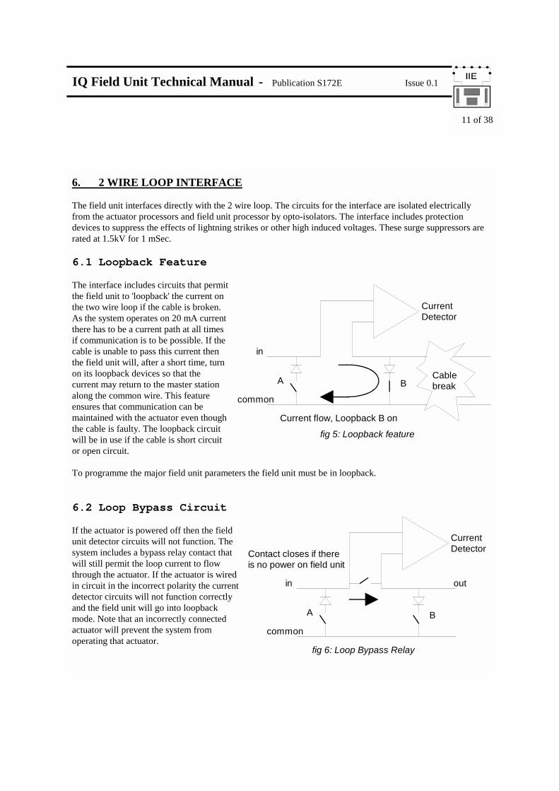
6. 2 WIRE LOOP INTERFACE The field unit interfaces directly with the 2 wire loop. The circuits for the interface are isolated electrically from the actuator processors and field unit processor by opto-isolators. The interface includes protection devices to suppress the effects of lightning strikes or other high induced voltages. These surge suppressors are rated at 1.5kV for 1 mSec. 6.1 Loopback Feature The interface includes circuits that permit the field unit to 'loopback' the current on the two wire loop if the cable is broken. As the system operates on 20 mA current there has to be a current path at all times if communication is to be possible. If the cable is unable to pass this current then the field unit will, after a short time, turn on its loopback devices so that the current may return to the master station along the common wire. This feature ensures that communication can be maintained with the actuator even though the cable is faulty. The loopback circuit will be in use if the cable is short circuit or open circuit. To programme the major field unit parameters the field unit must be in loopback. 6.2 Loop Bypass Circuit If the actuator is powered off then the field unit detector circuits will not function. The system includes a bypass relay contact that will still permit the loop current to flow through the actuator. If the actuator is wired in circuit in the incorrect polarity the current detector circuits will not function correctly and the field unit will go into loopback mode. Note that an incorrectly connected actuator will prevent the system from operating that actuator.
Cable break
Current flow, Loopback B on
A B
Current Detector
common
fig 5: Loopback feature
in
A B
Current Detector
common
fig 6: Loop Bypass Relay
in out
Contact closes if there is no power on field unit

IQ Field Unit Technical Manual - Publication S172E Issue 0.1
12 of 38
7. INPUT AND OUTPUT SIGNALS The following section describes the inputs and outputs of the field unit, plus the possible uses of the remote actuator inputs. In all cases feedback data is considered to flow from the actuator (or field) to the master station and command data in the reverse direction. Thus Inputs are feedback signals and Outputs are commands.
7.1 Digital Status Data Bits SUMMARY:
Digital Status Data Bits Actuator Data AUX1 - The remote input connected to input Aux 1 AUX2 - The remote input connected to input Aux 2 OAS - The actuator has reached the fully open position limit switch CAS - The actuator has reached the fully closed position limit switch STOP - The actuator is stationary and in mid travel MOVE - The actuator centre column is moving MRO - The actuator is running open MRC - The actuator is running closed. AUX3 - The remote input connected to input Aux 3. AUX4 - The remote input connected to input Aux 4. BATT - The status of the actuator internal battery.
��
OUTPUTS - COMMANDS (e.g. OPEN, CLOSE)
INPUTS - FEEDBACK SIGNALS (e.g. MOTOR RUNNING)
fig 7: Input and Output Data Directions
IQ Field Unit Technical Manual - Publication S172E Issue 0.1
13 of 38
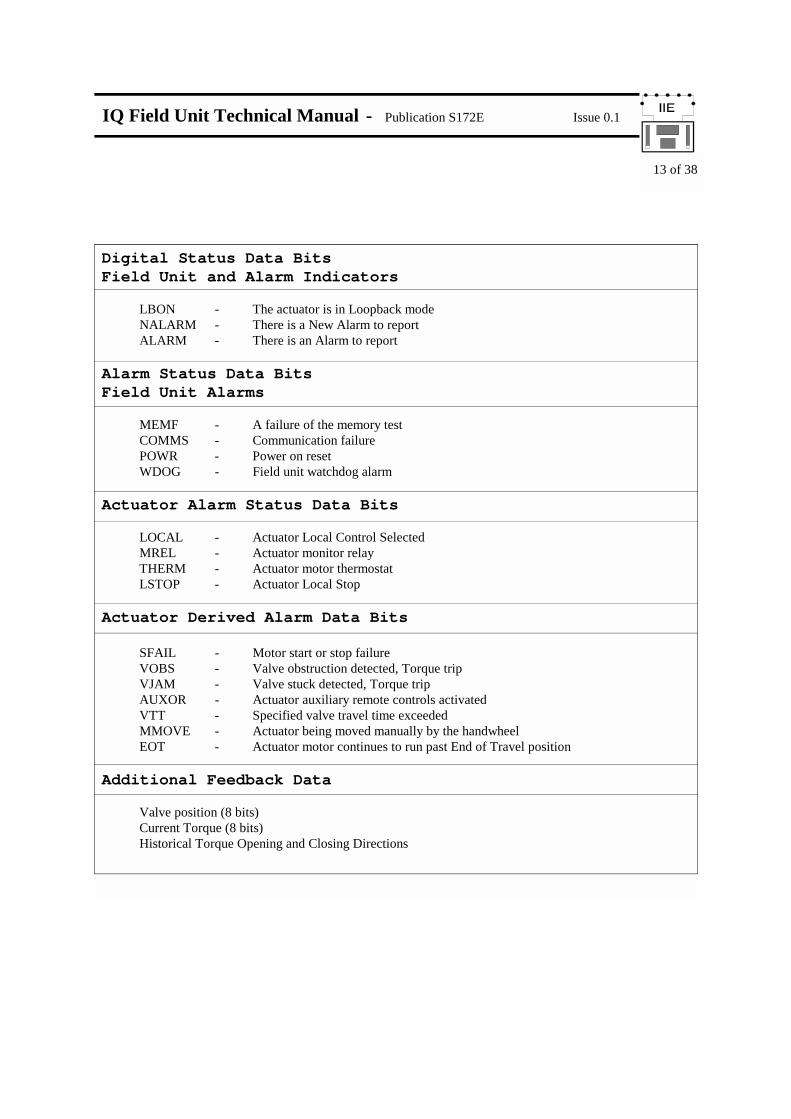
Digital Status Data Bits Field Unit and Alarm Indicators LBON - The actuator is in Loopback mode NALARM - There is a New Alarm to report ALARM - There is an Alarm to report Alarm Status Data Bits Field Unit Alarms MEMF - A failure of the memory test COMMS - Communication failure POWR - Power on reset WDOG - Field unit watchdog alarm Actuator Alarm Status Data Bits LOCAL - Actuator Local Control Selected MREL - Actuator monitor relay THERM - Actuator motor thermostat LSTOP - Actuator Local Stop Actuator Derived Alarm Data Bits SFAIL - Motor start or stop failure VOBS - Valve obstruction detected, Torque trip VJAM - Valve stuck detected, Torque trip AUXOR - Actuator auxiliary remote controls activated VTT - Specified valve travel time exceeded MMOVE - Actuator being moved manually by the handwheel EOT - Actuator motor continues to run past End of Travel position Additional Feedback Data Valve position (8 bits) Current Torque (8 bits) Historical Torque Opening and Closing Directions
IQ Field Unit Technical Manual - Publication S172E Issue 0.1
14 of 38
7.1.1 ACTUATOR POSITION LIMIT SWITCH DATA - ‘CAS’ & ‘OAS’ There are two data bits relating to the actuator set positions for open and close positions. OAS is used for open limit indication, CAS is used for close limit indication. These limit positions may be set within the actual valve stroke, as with a torque seating valve the actuator will stop when seated fully closed and the rated torque has been delivered to seat the valve. The position limit switch must be set slightly before the torque off position so as to ensure that the position is correctly reported. The actuator will continue to move in the chosen direction of travel for only 5 seconds after the limit switch position is reached, so the torque seat position must be quite close to the limit switch position. The data relating to position is maintained even though the position itself has been passed through. 7.1.2 STOP INDICATION DATA - ‘STOP’ Whenever the actuator centre column stops moving and it has not traversed or reached the end of travel limit switches it is stationary in mid travel. This situation is indicated by the STOP data bit. If the actuator is subsequently moved by either a 2 wire control input command, a local control command, a remote input command or by manually moving the valve the STOP signal will be removed for the duration of the movement of the centre column. 7.1.3 MOVE INDICATION DATA - ‘MOVE’ The actuator senses any movement of its centre column whether this is generated by a manual (hand) operation or by the action of the motor. Whenever the centre column is in motion the MOVE data bit is present. 7.1.4 MOTOR RUNNING DATA - ‘MRC’ & ‘MRC’ There are two data bits relating to the motor running and the direction of travel. Whenever one of the internal contactors is energised and the actuator begins to move the valve, either a MRO or MRC signal will be generated. If the contactor to run the actuator in the open direction is energised then MRO (Motor Running Open) is reported. If the contactor to run the actuator closed then MRC (Motor Running Closed) is reported. These signals will be reported if the actuator is commanded over the 2 wire loop to move or if it is commanded from the remote pushbuttons that can be fitted. Note: If the actuator has just been powered on and a command to move is generated from the actuator local controls, or an ESD input, then neither the MRO or MRC signal will be generated. In all cases a MOVE signal is always generated. This situation will revert to correct MRO or MRC indication (rather than no indication) once the actuator is switched to remote control and a command is issued to the valve via either the 2 wire loop or the remote pushbuttons. 7.1.5 REMOTE AUXILIARY INPUT SIGNALS - ‘AUX1’, ‘AUX2’, ‘AUX3’, ‘AUX4’ When the actuator is fitted with a Remote Input Board, the field unit is able to collect and use information from 4 remote input signals designated AUX1 - 4. These signals are reported to the master station over the 2 wire loop for all conditions set in the actuator. The data may relate to the use of some or all of these inputs as remote actuator controls, as remote input signals (for example from tank level switches) or a mixture of the two.
IQ Field Unit Technical Manual - Publication S172E Issue 0.1
15 of 38
7.1.6 AUX INPUT INVERT MASK The Aux inputs may report as a logic 1 or 0 for the input contact being a closed circuit. The decision as to whether a 1 or 0 is reported is made by the setting of the relevant data bit in the Invert Mask. Bits 0-3 relate to inputs AUX 1 - 4. If the bit in the mask is set to 1 then the data reported is a logic 1 when the contact source is closed, if the mask bit is set to 0 then the data is inverted, a closed contact source is reported as a 0. 7.1.7 AUX INPUT ACTION The Aux inputs may be used as a secondary control point for the actuator in which case they are designated as 'Remote Open', 'Remote Stop/Maintain', 'Remote Close' and 'ESD' signals. In order to enable the use of these signals as 'remote command inputs' the mask bits 4-7 must be set to '1' for the inputs being used. Note that by using both mask bit 0 (the inversion bit) and bit 4 (the enable bit) set to '1' results in Aux 1 being used as a normal 'Remote Open' command - a closing contact causes the actuator to run open. If an Aux input is used as a remote command input, including ESD, then when the Aux input is actioned an alarm bit (AUXOR) indicating that an auxiliary remote input command has been received is set. 7.1.8 BATTERY STATUS - ‘BATT’ The IQ actuator is fitted with a battery that is used to power the circuits used to keep track of the valve position. This battery is used only when the actuator has no power feed and the valve is actually moved. The condition of the battery is monitored at all times and a signal generated if the battery power is low. The field unit reports the condition of the battery in a data bit BATT. Remember that the field unit can only report information if the actuator is powered on. 7.1.9 LOOPBACK ON - ‘LBON’ The field unit will assert its loopback circuit when instructed to do so by the master station or if the field unit receives no messages within a specified time. A field units normal condition is to go into loopback a short time after it is powered on and remain in that state until told to remove its loopback by the master station. The condition of the loopback circuit is reported in the LBON data bit. Loopback is automatically asserted if there are no messages to the field unit. The time taken to be sure there are no messages is dependant on the loop baud rate set for the field unit. The periods are: 2400 baud 8 seconds 1200 baud 12 seconds 600 baud 24 seconds 300 baud 44 seconds 110 baud 90 seconds When interrogating a field unit with a Paktester the field unit will be in loopback. When programming the major parameters in a field unit the field unit must be in loopback.
IQ Field Unit Technical Manual - Publication S172E Issue 0.1
16 of 38
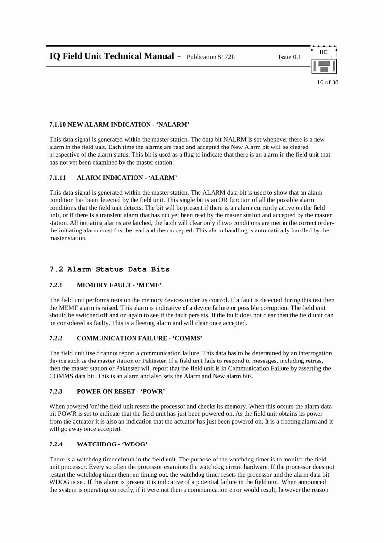
7.1.10 NEW ALARM INDICATION - ‘NALARM’ This data signal is generated within the master station. The data bit NALRM is set whenever there is a new alarm in the field unit. Each time the alarms are read and accepted the New Alarm bit will be cleared irrespective of the alarm status. This bit is used as a flag to indicate that there is an alarm in the field unit that has not yet been examined by the master station. 7.1.11 ALARM INDICATION - ‘ALARM’ This data signal is generated within the master station. The ALARM data bit is used to show that an alarm condition has been detected by the field unit. This single bit is an OR function of all the possible alarm conditions that the field unit detects. The bit will be present if there is an alarm currently active on the field unit, or if there is a transient alarm that has not yet been read by the master station and accepted by the master station. All initiating alarms are latched, the latch will clear only if two conditions are met in the correct order- the initiating alarm must first be read and then accepted. This alarm handling is automatically handled by the master station. 7.2 Alarm Status Data Bits 7.2.1 MEMORY FAULT - ‘MEMF’ The field unit performs tests on the memory devices under its control. If a fault is detected during this test then the MEMF alarm is raised. This alarm is indicative of a device failure or possible corruption. The field unit should be switched off and on again to see if the fault persists. If the fault does not clear then the field unit can be considered as faulty. This is a fleeting alarm and will clear once accepted. 7.2.2 COMMUNICATION FAILURE - ‘COMMS’ The field unit itself cannot report a communication failure. This data has to be determined by an interrogation device such as the master station or Paktester. If a field unit fails to respond to messages, including retries, then the master station or Paktester will report that the field unit is in Communication Failure by asserting the COMMS data bit. This is an alarm and also sets the Alarm and New alarm bits. 7.2.3 POWER ON RESET - ‘POWR’ When powered 'on' the field unit resets the processor and checks its memory. When this occurs the alarm data bit POWR is set to indicate that the field unit has just been powered on. As the field unit obtains its power from the actuator it is also an indication that the actuator has just been powered on. It is a fleeting alarm and it will go away once accepted. 7.2.4 WATCHDOG - ‘WDOG’ There is a watchdog timer circuit in the field unit. The purpose of the watchdog timer is to monitor the field unit processor. Every so often the processor examines the watchdog circuit hardware. If the processor does not restart the watchdog timer then, on timing out, the watchdog timer resets the processor and the alarm data bit WDOG is set. If this alarm is present it is indicative of a potential failure in the field unit. When announced the system is operating correctly, if it were not then a communication error would result, however the reason

IQ Field Unit Technical Manual - Publication S172E Issue 0.1
17 of 38
for the alarm should be determined. Accepting the alarm will cause it to go away, it is a fleeting alarm, but if it returns then it should be assumed that the field unit is about to fail completely. 7.2.5 LOCAL - ‘LOCAL’ The actuator has a 3 position switch for selecting Remote, Local Stop or Local control. The switch passes from Remote to Local, or Local to Remote, through the Local Stop position. When the actuator local control switch is fully in the Local position then the LOCAL alarm bit is generated. This data bit is not present when the actuator control switch is in the Local Stop or Remote positions. The alarm is present as long as the switch is in the Local position, it will clear only when accepted and the switch is returned to the Remote or Local Stop position. If the switch is returned to the Remote or Local Stop position before the alarm is accepted, then on acceptance the alarm bit will clear. 7.2.6 LOCAL STOP - ‘LSTOP’ When the actuator local control switch passes through, or is set in, the Local Stop position then the alarm bit LSTOP is set. The actuator may be placed in Local Stop as a unique function to prevent operation of the valve by any remote means. Note that LSTOP will be generated when moving the selector switch from Remote to Local and when moving the switch from Local to Remote. If the selector switch simply traverses the Local Stop position then the alarm generated will be fleeting and will clear itself on the next 'read and accept' cycle. 7.2.7 THERMOSTAT TRIP - ‘THERM’ The actuator motor is protected by a thermostat, if the temperature of the motor windings rises above the thermostat trip value then the THERM alarm bit is set. There are no adjustments for the temperature at which the thermostat trip operates. The motor will be stopped if the thermostat trips. Only once the motor has cooled down can a new Remote, Pakscan or Local command to move the actuator Open or Closed be actioned. The ESD command may be set to override the thermostat. The THERM alarm bit will remain set until the motor cools down and until read and accepted. 7.2.8 MONITOR RELAY - ‘MREL’ The actuator includes a composite signal for some alarms referred to as the Monitor relay. The MREL alarm bit will be set if the actuator selector is in Local or Local Stop (not in Remote) or if the thermostat trips. The actuator also monitors the 3 phase supply, if the phase not associated with the control circuits is lost the monitor relay will operate and the MREL data bit is raised. The remaining two phases are used by the control circuits and if either of these is lost at any time then the actuator switches off. Communication with the field unit will then be lost. The MREL alarm bit remains set until read and accepted, and the condition returns to normal. 7.2.9 START/STOP FAILURE - ‘SFAIL’ The actuator must be set in Remote for this alarm to be valid. If the actuator motor fails to respond to a valid Pakscan or Remote Auxiliary Input start or stop signal then the field unit will raise the SFAIL alarm bit. The SFAIL bit is not raised if the alarm is detected as an obstructed or jammed valve. The alarm is fleeting and only generated at the time the failure occurs. The alarm bit will clear once it has been read and accepted.

IQ Field Unit Technical Manual - Publication S172E Issue 0.1
18 of 38
7.2.10 OBSTRUCTED VALVE, TORQUE TRIP - ‘VOBS’ The actuator must be set in Remote for this alarm to be valid. If the actuator is required to generate more torque than the actuator maximum torque setting the motor will stop. The field unit detects this internal condition and modifies it to include the fact that the actuator is not currently in its end of travel position. The reason for the stopped condition must therefore be an excessive stiffness in the valve or an obstruction in the pipe preventing the valve from moving any further in the selected direction. The alarm reported is VOBS. If the valve movement stops in mid travel due to the drive becoming disconnected, for example by being placed in hand operation, then the actuator detects the loss of motion of the centre column and VOBS is reported. The VOBS alarm bit is fleeting and will clear once read and accepted. Note: If the valve is obstructed and the actuator stops, attempting to restart the actuator to move towards the obstruction (even if the obstruction is no longer present) will generate an SFAIL alarm. The actuator must be reversed away from the obstruction before attempting to continue in the original direction. 7.2.11 JAMMED VALVE, TORQUE TRIP - ‘VJAM’ The actuator must be set in Remote for this alarm to be valid. This signal is similar to the SFAIL Start/Stop failure alarm. In the case of the VJAM alarm the actuator stall condition will be detected whilst the actuator is stationary at an end of travel position. The torque trip will have been generated because the valve is stuck in the seat. If the actuator is set to stop on torque, to guarantee a fully shut or open valve irrespective of the position limit switch setting, then the VJAM alarm is not generated at the end of travel position. The alarm is only generated when the actuator attempts to leave the valve seated condition. The VJAM alarm bit is fleeting and will clear once read and accepted. 7.2.12 AUXILIARY OVERRIDE INPUT DETECTED - ‘AUXOR’ The actuator must be set in Remote for this alarm to be valid. The actuator is capable of being operated by Remote Auxiliary Input signals for Open, Stop, Close and ESD. If one of these inputs is generated then the AUXOR alarm bit is set. The function is to announce that the actuator has been asked to move from this signal source. The AUXOR alarm bit is fleeting and will clear once read and accepted. 7.2.13 VALVE TRAVEL TIME - ‘VTT’ The actuator must be set in Remote for this alarm to be valid. If the field unit detects that the actuator is in motion for a time greater than the setting of the travel time trip then the VTT alarm bit is set. The alarm will not cause the actuator to stop. The VTT alarm bit is fleeting and will clear once read and accepted. 7.2.14 MANUAL VALVE MOVEMENT - ‘MMOVE’ The actuator must be set in Remote for this alarm to be valid. If the valve is placed in hand operation and moved by the handwheel the actuator detects the motion of the centre column. This motion will set the MMOVE alarm bit. The MMOVE alarm bit is fleeting and will clear once read and accepted. 7.2.15 MOTOR CONTINUES RUNNING AT END OF TRAVEL LIMIT POSITION - ‘EOT’ The actuator must be set in Remote for this alarm to be valid. If the actuator motor continues to run for more than 5 seconds after the valve reaches the set end of travel limit switch position then the EOT alarm bit is set. The EOT alarm bit is fleeting and will clear once read and accepted.
IQ Field Unit Technical Manual - Publication S172E Issue 0.1
19 of 38
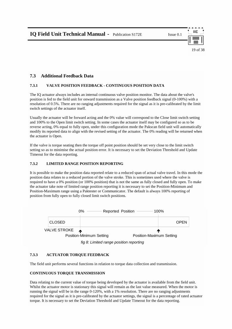
7.3 Additional Feedback Data 7.3.1 VALVE POSITION FEEDBACK - CONTINUOUS POSITION DATA The IQ actuator always includes an internal continuous valve position monitor. The data about the valve's position is fed to the field unit for onward transmission as a Valve position feedback signal (0-100%) with a resolution of 0.5%. There are no ranging adjustments required for the signal as it is pre-calibrated by the limit switch settings of the actuator itself. Usually the actuator will be forward acting and the 0% value will correspond to the Close limit switch setting and 100% to the Open limit switch setting. In some cases the actuator itself may be configured so as to be reverse acting, 0% equal to fully open, under this configuration mode the Pakscan field unit will automatically modify its reported data to align with the revised setting of the actuator. The 0% reading will be returned when the actuator is Open. If the valve is torque seating then the torque off point position should be set very close to the limit switch setting so as to minimise the actual position error. It is necessary to set the Deviation Threshold and Update Timeout for the data reporting. 7.3.2 LIMITED RANGE POSITION REPORTING It is possible to make the position data reported relate to a reduced span of actual valve travel. In this mode the position data relates to a reduced portion of the valve stroke. This is sometimes used where the valve is required to have a 0% position (or 100% position) that is not the same as fully closed and fully open. To make the actuator take note of limited range position reporting it is necessary to set the Position-Minimum and Position-Maximum range using a Paktester or Communicator. The default is always 100% reporting of position from fully open to fully closed limit switch positions.
7.3.3 ACTUATOR TORQUE FEEDBACK The field unit performs several functions in relation to torque data collection and transmission. CONTINUOUS TORQUE TRANSMISSION Data relating to the current value of torque being developed by the actuator is available from the field unit. Whilst the actuator motor is stationary this signal will remain as the last value measured. When the motor is running the signal will be in the range 0-120%, with a 1% resolution. There are no ranging adjustments required for the signal as it is pre-calibrated by the actuator settings, the signal is a percentage of rated actuator torque. It is necessary to set the Deviation Threshold and Update Timeout for the data reporting.
CLOSED OPEN
VALVE STROKE
0% 100%
Position-Minimum Setting Position-Maximum Setting
Reported Position
! !
fig 8: Limited range position reporting

IQ Field Unit Technical Manual - Publication S172E Issue 0.1
20 of 38
HISTORICAL TORQUE TRANSMISSION The field unit collects torque values as the valve traverses from open to closed. These signals are then available from the field unit for display on the master station or Communicator. The values are ranged 0-120% of rated torque with a 1% resolution. Eight readings are recorded in each direction of travel, there are 16 readings in total. Readings are not taken at the fully open (100%) position or the fully closed (0%) position as the torque generated in these positions will be that set for the actuator if the valve is torque seating. Torque is not recorded for the first 100 mSec of motor movement as during this time the readings will be subject to transient interference. The torque records are related to valve positions 6%, 19%, 31%, 44%, 56%, 69%, 81% and 94% open. If the valve does not travel for its full stroke only the entries relating to the proportion of the span being used will be updated. If a reduced range of operation has been selected by setting the position minimum and maximum parameters the torque records will correspond to the reduced range of position data.
The field unit also includes a 'filter' that may be applied to these readings. If raw data is required then the filter should be set to zero. The master station will only collect raw data as a routine function (i.e. the filter must be set to 0), if filtered data is needed it must be specifically requested from the appropriate master station screen. Filtered data is not available to a master station host. The filter applies a weighted average to the measurements taken, averaging takes a proportion of the current torque value for a given position and a proportion of the new measurement and adds them together. The Filter factor may be set in the range 0 - 255. The calculation uses the following formula:
CLOSED OPEN
VALVE STROKE
0% 100%
Position-Minimum Setting Position-Maximum Setting
Reported Position
! !
fig 9: Torque log reporting - Limited range position
6% 19% 31% 44% 56% 69% 81% 94%
0 1 2 4 5 6 73
TORQUE LOG ENTRIES
Reported Value = New value (1 - Filter Factor)256
Old value (Filter Factor)256
+
Example:Old (Previous) torque reading = 40New (Raw) torque reading = 60Filter factor = 128 (50%)
Record Entry for 'Filtered' Torque = 60(1 - 128) + 40(128)
= 60 x 0.5 + 40 x 0.5= 50
256 256

IQ Field Unit Technical Manual - Publication S172E Issue 0.1
21 of 38
7.4 Command Outputs The actuator is able to be commanded either from the local controls, the Pakscan field unit, or the Remote Auxiliary Inputs. Local controls will always preclude remote controls when actuator is in local. When Remote is selected the options for control have priorities as indicated in figure 10. The actuator will always respond to the last Open/Stop/Close input or DV command. If the command is an ESD then it will override any other command.
7.4.1 LOCAL CONTROLS (OPEN, STOP, CLOSE) The selector switch must be in Local for the Local Open or Local Close controls to be actioned. When commanded the actuator will move in the desired direction. The actuator is able to accept instantaneous reversal of direction of travel without the need for a stop signal. Local Stop is a unique position for the selector switch and causes the actuator to stop. Whenever the actuator is in Local or Local Stop no other input from Pakscan or the Remote Auxiliary Inputs will cause actuator motion. In Local control mode no derived alarms are generated by the Pakscan system. 7.4.2 PAKSCAN CONTROLS (OPEN, STOP, CLOSE AND SET DV) The actuator selector switch must be in Remote for Pakscan control to be enabled. The field unit is able to command the actuator to move full travel or to a particular position. FULL TRAVEL CONTROL The field unit outputs Open, Stop and Close commands that are actioned by the actuator. When the field unit issues a command the actuator actions it until another command is issued or the instruction has been completed. For example the field unit will issue a command to 'open' the valve, the actuator will then action this command until the valve is fully open or until a close or stop command is issued from the field unit, whichever is the sooner. If an attempt to issue simultaneous commands is made then a priority exists such that Stop is the highest and Open is the lowest. The command to the field unit from the 2 wire loop is a momentary 'write' of data. Once initiated the field unit does not require the command to be cancelled before another is issued. Since the command to the actuator itself is a fleeting signal it is not possible to 'read back' the status of command data. If multiple commands are sent to the same field unit the command received last will be obeyed. Note that as commands are processed by the master station it is possible for a multiple coil or register write the order could be reversed. If single coil write commands are used on the host data link this possibility is eliminated. It is acceptable to reverse the actuator in mid travel without issuing a stop command.
fig 10: Command priorities
High Priority Low Priority
Aux Input ESDMaster Station ESD
Aux Input STOP Aux Input CLOSE Aux Input OPEN
Master Station STOPMaster Station CLOSEMaster Station OPEN
""""""" """"""" """"""" """""""
Local Stop Local Close Local Open

IQ Field Unit Technical Manual - Publication S172E Issue 0.1
22 of 38
It is not possible to induce a 'push to run' action with a Pakscan system. The actuator will run in the chosen direction to the end of travel unless stopped by another command. 7.4.2 POSITION CONTROL (SET DV) Position control should be used on forward acting valves only. The field unit is able to accept a 'Desired Value' signal to cause the actuator to move to a particular position in the valve stroke. The action of sending a DV signal to the field unit places it in 'positioning mode'. The command has a lower priority than a full travel Open command. The positioning signal must be in the range 0-100% where 0% is towards the close position of the valve. Once a desired value has been sent to the actuator the field unit will maintain control of the actuator and position it such that the measured value position signal equals the desired value sent. This control will be continued until it is replaced with a new command. If at any time an alarm occurs the control action will be cancelled. When the actuator has been set for limited range position reporting it will take the 0-100% position range over a portion of the total valve stroke. If a Desired Value position is sent to the actuator it will use the same limited range for positioning the actuator as it uses for reporting the actual position. A full travel command will move the actuator over the full range to the appropriate limit switch position. The command to the field unit from the 2 wire loop is a momentary 'write' of data for the Desired Value. Once initiated the field unit does not require the command to be cancelled before another is issued. Since the command to the field unit is then interpreted as instructions to the actuator itself it is not possible to 'read back' the Desired Value. It is acceptable to send a new Desired Value at any time, there is no need to issue a stop command or cancel the existing value. If a full travel command (such as Open, Stop or Close) is sent to the field unit this will cause the Desired Value command to be removed and replaced with the most recent command. In situations where multiple register writes to the master station are sent to the same field unit then the last Desired Value command received by the field unit will be the command actioned. When any alarm is detected by the field unit then the position control action is cancelled and the actuator will not attempt to continue controlling the valve position. This means that, for example, if the valve is obstructed during a positioning action the actuator will stop and not continue to try to achieve the desired position. The alarm reason should be investigated and corrected before any further attempt is made to position the actuator. A Remote Auxiliary Control input becoming active will also cancel the position control action. If an alarm is already present on the actuator and a DV command is sent to the field unit then the command will not be actioned and it will be discarded. For example if the actuator selector is in Local Stop and a DV position command is sent to the field unit, when the selector is moved to Remote the actuator will NOT run to obey the DV command.

IQ Field Unit Technical Manual - Publication S172E Issue 0.1
23 of 38
ACTUATOR PROTECTION IN POSITION CONTROL MODE The actuator includes several settings designed to prevent damage to the actuator when a DV signal is being actioned. a) Motion Inhibit Timer The setting of the Motion Inhibit Timer is the period that must elapse between the actuator stopping and then restarting. This idle period will prevent the actuator motor exceeding its rated starts per hour. b) Deadband Setting The control algorithm used for the Pakscan field unit positioner is proportional only. The field unit runs the actuator to the desired position and then stops it. As the actuator and valve combination will have some inertia it is possible that the desired position may be 'overrun' and the positioner will then reverse the actuator direction of travel in order to make the valve adopt the desired position. This phenomena is termed 'hunting'. The actuator/valve combination may hunt around the control point if the inertia is high. To prevent this from happening there is a Deadband setting whereby once the actuator enters the deadband the motor will be stopped. For example a 5% deadband will cause the motor to be stopped once the actual position is within 5% of the desired position. The inertia will then bring the actual position nearer to the desired position. It is important to set the deadband such that the actuator does not hunt around the control point. c) Hysteresis In addition to the deadband setting there is also a setting for Hysteresis. The field unit positioner will run the actuator until the actual position is within the deadband setting minus the hysteresis setting. This has the effect of instructing the actuator to stop when the position is nearer to the desired position. The actuator will not start again unless the deadband is exceeded.
CLOSED OPEN
VALVE STROKE 0% 100%
Position-Minimum Setting Position-Maximum Setting! !
fig 11: Deadband and Hysteresis Settings
DV = 40%MV = 40%
Deadband = 3%Hysteresis = 1%
37% 38% 39% 40% 41% 42% 43%
DeadbandHysteresis Hysteresis
Deadband

IQ Field Unit Technical Manual - Publication S172E Issue 0.1
24 of 38
7.4.3 REMOTE AUXILIARY CONTROL INPUTS Some or all of the four auxiliary contact input signals may be used as remote control inputs to operate the actuator. For any of these inputs to be actioned the actuator selector switch must be set in Remote. CONFIGURING THE REMOTE CONTROL AUXILIARY INPUTS The function of the four inputs are predefined when they are used as control inputs. Note that a mixture of control inputs and data reporting inputs is acceptable. The actuator operation may be set to either ‘Maintained’ or ‘Push to Run’. In Maintained mode the actuator will run full travel for a momentary contact input change, in Push to Run mode the actuator motion is only present whilst the input initiation contact is present. AUX 3 determines the type of control. AUX 1 - REMOTE OPEN AUX 2 - REMOTE CLOSE AUX 3 - REMOTE STOP/MAINTAIN AUX 4 - EMERGENCY SHUT DOWN The Auxiliary Input Configuration Mask must be enabled for the desired function to be set into the actuator. When this is suitably set the Remote Auxiliary Inputs will be Remote Auxiliary Control inputs. If any one or more Remote Auxiliary Inputs is operated the AUXOR alarm signal is generated. These controls override any existing Pakscan command or Position control action except for a Pakscan ESD command. If AUX 3 (Remote Stop/Maintain) is not enabled then the actuator will adopt a Maintained operation mode where a momentary input will cause full travel of the valve. 7.4.4 EMERGENCY SHUT DOWN The obtained result of an ESD command is programmed into the actuator itself and may cause the valve to Close, Open or No Action. The ESD action may also override the actuator thermostat. The Auxiliary Input 4 (AUX 4) can be configured for a contact input to cause an actuator ESD action. The actuator may receive an ESD command from either the Auxiliary Input ESD Command (AUX 4) or from the Pakscan loop. The ESD command has the highest priority with the Auxiliary Input ESD Command having the highest. All existing control commands are cancelled and replaced by the ESD action. When the ESD input is from a contact connected to AUX 4 the resulting action may be either Maintained mode, where the actuator moves the valve full travel, or Push to Run mode where the actuator moves the valve only whilst the input is present, depending whether AUX 3 is enabled (AUX 3 is the Remote Stop/Maintain input). If AUX 3 is not enabled then the action is Maintained mode. When the ESD signal is initiated from the Pakscan system the action is latched into the field unit and it is not possible to move the actuator by the Local controls until the ESD action is unlatched. The latch may only be released by a new Pakscan generated remote control signal. The actuator movement is always as Maintained mode (irrespective of the AUX 3 input). An ESD from the Pakscan system cannot be unlatched by a Remote Auxiliary Input command. It can be unlatched only by a Pakscan command.

IQ Field Unit Technical Manual - Publication S172E Issue 0.1
25 of 38
8. ALARM HANDLING Alarm handling is automatically controlled by the master station. The user need not consider how alarms are latched and reported by the field unit. Any alarm revealed by the field unit will be reported to the master station. The user should be aware of how to handle the alarms at the master station and on the master station to host computer communication link. If an alarm is reported by the field unit it is automatically accepted by the master station. The alarm is then free to clear once the actuator returns to normal. In the master station the alarm is posted to three logically separate areas, the data base for comms port 1, the data base for comms port 2, and the screen display. In all cases the alarm must be read either by viewing the screen or requesting the data before the alarm can be removed from the system. Once it has been read then the alarm will only clear on two further conditions, it must be accepted and the fault must clear. Until all three conditions are met the alarm will remain locked in the system. If an alarm has not been cleared and subsequently repeats itself then the more recent event overwrites the earlier event. In the case of a logging printer being attached to the master station both the events will be logged.
fig 12: Alarm handling sequences
a) Alarm present after Host read and Accept
b) Short period transient alarm
c) alarm returns to normal between Host read and Accept
Alarm on Actuator e.g. Local Stop
Alarm Status in Master Station
Host Actiontime
Read Alarm
Accept Alarm
Read Alarm
Accept Alarm
Read Alarm
Accept Alarm
IQ Field Unit Technical Manual - Publication S172E Issue 0.1
26 of 38
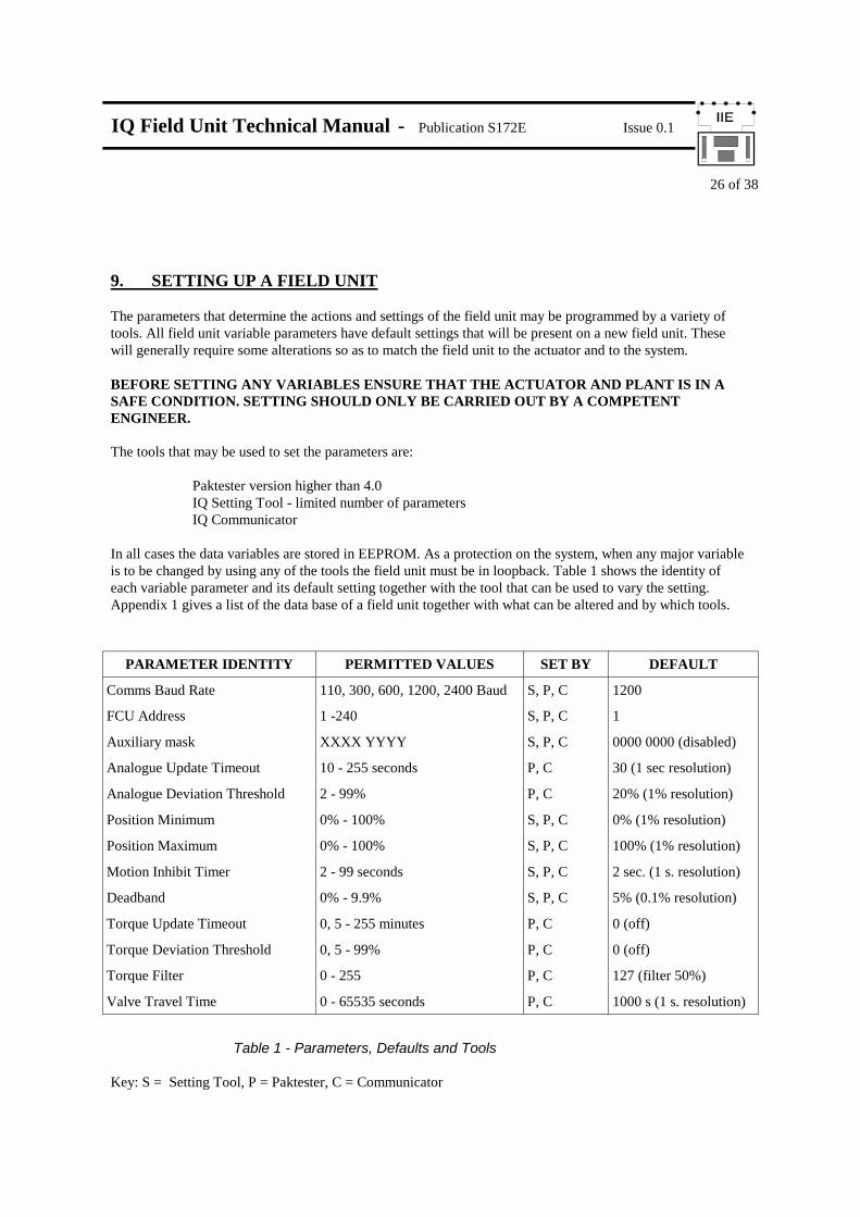
9. SETTING UP A FIELD UNIT The parameters that determine the actions and settings of the field unit may be programmed by a variety of tools. All field unit variable parameters have default settings that will be present on a new field unit. These will generally require some alterations so as to match the field unit to the actuator and to the system. BEFORE SETTING ANY VARIABLES ENSURE THAT THE ACTUATOR AND PLANT IS IN A SAFE CONDITION. SETTING SHOULD ONLY BE CARRIED OUT BY A COMPETENT ENGINEER. The tools that may be used to set the parameters are: Paktester version higher than 4.0 IQ Setting Tool - limited number of parameters IQ Communicator In all cases the data variables are stored in EEPROM. As a protection on the system, when any major variable is to be changed by using any of the tools the field unit must be in loopback. Table 1 shows the identity of each variable parameter and its default setting together with the tool that can be used to vary the setting. Appendix 1 gives a list of the data base of a field unit together with what can be altered and by which tools.
Table 1 - Parameters, Defaults and Tools Key: S = Setting Tool, P = Paktester, C = Communicator
PARAMETER IDENTITY PERMITTED VALUES SET BY DEFAULT
Comms Baud Rate 110, 300, 600, 1200, 2400 Baud S, P, C 1200
FCU Address 1 -240 S, P, C 1
Auxiliary mask XXXX YYYY S, P, C 0000 0000 (disabled)
Analogue Update Timeout 10 - 255 seconds P, C 30 (1 sec resolution)
Analogue Deviation Threshold 2 - 99% P, C 20% (1% resolution)
Position Minimum 0% - 100% S, P, C 0% (1% resolution)
Position Maximum 0% - 100% S, P, C 100% (1% resolution)
Motion Inhibit Timer 2 - 99 seconds S, P, C 2 sec. (1 s. resolution)
Deadband 0% - 9.9% S, P, C 5% (0.1% resolution)
Torque Update Timeout 0, 5 - 255 minutes P, C 0 (off)
Torque Deviation Threshold 0, 5 - 99% P, C 0 (off)
Torque Filter 0 - 255 P, C 127 (filter 50%)
Valve Travel Time 0 - 65535 seconds P, C 1000 s (1 s. resolution)

IQ Field Unit Technical Manual - Publication S172E Issue 0.1
27 of 38
COMMUNICATION BAUD RATE Must be set to 110, 300, 600, 1200, or 2400 baud. All the Field Units on the loop must be set to the same base speed baud rate. FIELD UNIT ADDRESS Must be set in the range 1-240. On a single 2 wire loop each Field Unit must have a unique address. The order of the addresses on the loop need not be consecutive. For reasons of speed performance it is best to have no unused addresses on the loop. REMOTE AUXILIARY INPUT MASK Must be set for the desired function of the Remote Input board. If there are no Remote Auxiliary inputs then the default setting may be left in place. The 8 data bits in the mask relate to the function and contact sense of the inputs. The 4 most significant bits (4 to 7) relate to the use of the inputs for actuator control, if a '1' is put in the mask in the appropriate position then that input is enabled as an actuator control input, if a '0' is placed in the mask then the input becomes a reported signal only. The 4 least significant bits (0 to 3) relate to the sense of the input. A '1' placed in the appropriate bit makes a contact closure achieve the action or be reported as a '1' on the data communications. A ‘0’ placed in the bit inverts the signal and makes a contact opening achieve the action or be reported as a ‘1’.
Aux 1 Bit 0 0 Report closed contact input as ‘0’, action as control input if enabled
1 Report closed contact input as ‘1’, action as input if enabled
Aux 2 Bit 1 0 Report closed contact input as ‘0’, action as input if enabled
1 Report closed contact input as ‘1’, action as input if enabled
Aux 3 Bit 2 0 Report closed contact input as ‘0’, action as input if enabled
1 Report closed contact input as ‘1’, action as input if enabled
Aux 4 Bit 3 0 Report closed contact input as ‘0’, action as input if enabled
1 Report closed contact input as ‘1’, action as input if enabled
Aux 1 Bit 4 0 Disable Aux 1 as ‘OPEN’ command
1 Enable Aux 1 as ‘OPEN’ command
Aux 2 Bit 5 0 Disable Aux 2 as ‘CLOSE’ command
1 Enable Aux 2 as ‘CLOSE’ command
Aux 3 Bit 6 0 Disable Aux 3 as ‘STOP/MAINTAIN’ input, all remote inputs always maintained mode
1 Enable Aux 3 as ‘STOP/MAINTAIN’ input
Aux 4 Bit 7 0 Disable Aux 4 as ‘ESD’ command
1 Enable Aux 4 as ‘ESD’ command

IQ Field Unit Technical Manual - Publication S172E Issue 0.1
28 of 38
The auxiliary input mask takes the form:
Key: Enable = 1 to enable the input as a Remote Control Input Invert = 1 for a normally open input contact to achieve the action Example 1: Remote auxiliary control ESD input contact, opening to cause ESD, Actuator to be Push to Run [no connection need be made to the Aux 3 (Stop/Maintain input)]. Example 2: Remote auxiliary control ESD input contact, opening to cause ESD, Remote Open and Close inputs where a closing contact causes the actuator motion, all motion to be Maintained mode. Example 3: Remote auxiliary control ESD input contact, closing to cause ESD, Remote Open and Close inputs where a closing contact causes the actuator motion, all motion in Maintained mode, Aux 3 input utilised for a contact input that reports its state over the Pakscan system, when the Aux 3 contact is closed a ‘1’ is reported. ANALOGUE UPDATE TIME Must be set for the period to update the master station with analogue position data. The valve position is reported each time it changes by more than the Analogue Deviation or every 'x' seconds where 'x' is the Analogue Update Time. As the value updates on deviation whilst the valve is moving the update time can be set to quite a long period and should be approximately 10 times the loop scan period. If analogue data is not being used at all then the Update Time should be turned off by setting it to zero (0). ANALOGUE DEVIATION THRESHOLD Must be set for the amount of change that has to occur before the analogue position data is reported to the master station. The valve position is reported each time the value changes by the Analogue Deviation setting or every Update Time period. Whilst the valve is in motion reports about its position will be made each time the position changes by more than the Deviation setting. The recommended value is 5% where analogue data is required. If analogue data is not being used then the Deviation should turned off by setting it to zero (0). 0% AND 100% POSITIONS - LIMITED RANGE POSITION REPORTING Where the analogue Valve Position data is to be reported over only part of the total valve stroke the settings for minimum and maximum position have to be made. The 0% position is that point in the stroke where the analogue data will report 0%, the 100% position is where it will report 100%. Between these two settings the position reported is a proportion of the travel between these two positions.
Most significant bit
Bit 7 Bit 6 Bit 5 Bit 4 Bit 3 Bit 2 Bit 1 Bit 0
Enable Aux 4 (ESD)
Enable Aux 3 (Stop/
Maintain)
Enable Aux 2
(Close)
Enable Aux 1 (Open)
Invert Aux 4
Invert Aux 3
Invert Aux 2
Invert Aux 1
Example 1 1 1 0 0 0 1 X X
Example 2 1 0 1 1 0 X 1 1
Example 3 1 0 1 1 1 1 1 1
Least significant bit
IQ Field Unit Technical Manual - Publication S172E Issue 0.1
29 of 38
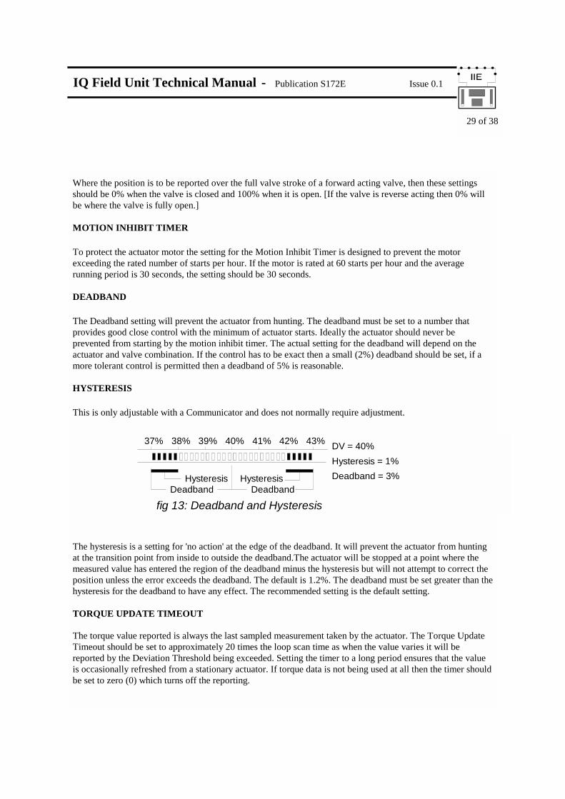
Where the position is to be reported over the full valve stroke of a forward acting valve, then these settings should be 0% when the valve is closed and 100% when it is open. [If the valve is reverse acting then 0% will be where the valve is fully open.] MOTION INHIBIT TIMER To protect the actuator motor the setting for the Motion Inhibit Timer is designed to prevent the motor exceeding the rated number of starts per hour. If the motor is rated at 60 starts per hour and the average running period is 30 seconds, the setting should be 30 seconds. DEADBAND The Deadband setting will prevent the actuator from hunting. The deadband must be set to a number that provides good close control with the minimum of actuator starts. Ideally the actuator should never be prevented from starting by the motion inhibit timer. The actual setting for the deadband will depend on the actuator and valve combination. If the control has to be exact then a small (2%) deadband should be set, if a more tolerant control is permitted then a deadband of 5% is reasonable. HYSTERESIS This is only adjustable with a Communicator and does not normally require adjustment.
The hysteresis is a setting for 'no action' at the edge of the deadband. It will prevent the actuator from hunting at the transition point from inside to outside the deadband.The actuator will be stopped at a point where the measured value has entered the region of the deadband minus the hysteresis but will not attempt to correct the position unless the error exceeds the deadband. The default is 1.2%. The deadband must be set greater than the hysteresis for the deadband to have any effect. The recommended setting is the default setting. TORQUE UPDATE TIMEOUT The torque value reported is always the last sampled measurement taken by the actuator. The Torque Update Timeout should be set to approximately 20 times the loop scan time as when the value varies it will be reported by the Deviation Threshold being exceeded. Setting the timer to a long period ensures that the value is occasionally refreshed from a stationary actuator. If torque data is not being used at all then the timer should be set to zero (0) which turns off the reporting.
fig 13: Deadband and Hysteresis
DV = 40%
Deadband = 3%Hysteresis = 1%
37% 38% 39% 40% 41% 42% 43%
DeadbandHysteresis
DeadbandHysteresis

IQ Field Unit Technical Manual - Publication S172E Issue 0.1
30 of 38
TORQUE DEVIATION THRESHOLD Must be set for the amount of change that has to occur before the continuous torque data is reported to the master station. The torque is reported each time the value changes by the Torque Deviation setting or every Update Time period. Whilst the valve is in motion reports about the current torque value will be made each time the torque changes by more than the Deviation setting. The recommended value is 5% where continuous torque data is required. If torque data is not being used then the deviation should be set to 0% which turns off the reporting. TORQUE FILTER If the Torque historical logging is being used then the Torque filter must be set OFF (0=Off). If the historical torque profile of values against position are being used as a diagnostic aid for examination on either the master station screen (when called up on the appropriate display) or for display on a Communicator then the Torque Filter is set for the degree of averaging required. The filter introduces a weighted average such that:
MAXIMUM VALVE TRAVEL TIME This should be set to a value 10% greater than the actual valve travel time. Note that the setting is relative to the time the actuator is in motion.
Reported Value = New value (1 - Filter Factor)256
Old value (Filter Factor)256
+

IQ Field Unit Technical Manual - Publication S172E Issue 0.1
31 of 38
9.1 Using a Paktester The Paktester must be connected to the 2 wire loop terminals of the actuator and the actuator must be powered on. Only one actuator may be connected to the Paktester at a time. Full details of the procedure for using the Paktester are included in the manual about that product. The required variable can be programmed using the 'Programme' button on the Paktester and by then inserting the new values on the screens as they appear. 9.2 Using a Setting Tool The Setting Tool accesses the field unit via the infra-red data link. The actuator must be in loopback before any major variables can be changed, it also needs to be powered on. To ensure a field unit is in loopback power off the master station or disconnect the 2 wire loop from the master station. The Setting Tool menus list the methods for accessing the parameters in the field unit that can be changed, in order to access these menus the option must be set 'on' [OP]. If the Setting Tool is being used for adjusting position control data then the Folomatic menu option must also be set 'on' [ON]. Full details are included in the Setting Tool manual. 9.3 Using a Communicator The Communicator accesses the field unit via the infra-red data link. For setting most parameters the actuator need not be in loopback. It is recommended that the settings are not changed whilst the actuator is in use. Full details of the use of the Communicator for setting the Pakscan variables is included in the Communicator manual.

IQ Field Unit Technical Manual - Publication S172E Issue 0.1
32 of 38
10. MAINTENANCE AND REPAIR There is no periodic service requirement for the field unit. Repairs should not be attempted on the field unit. Any failure should be rectified by replacing the field unit with new compatible device. Static sensitive and CMOS devices are used in the field unit. It is therefore mandatory to observe anti-static precautions when handling or working on a field unit. The field unit may be stored for a period of up to 10 years in clean conditions. 11. RECORDS The following information should be recorded for each field unit (M = Major Parameter) :
Valve Tag:
Actuator Serial Number:
M Field Unit Address:
M Loop Baud Rate
Analogue Update Time
Analogue Deviation Threshold
Motion Inhibit Timer
Deadband
Hysteresis
Auxiliary Mask Setting
0% Limited Position setting (%of full stroke)
100% Limited Position setting (%of full stroke)
Torque Update Time
Torque Deviation Threshold
Torque Filter
Valve travel Time

IQ Field Unit Technical Manual - Publication S172E Issue 0.1
33 of 38
APPENDIX 1. PARAMETER ACCESS TABLE (All numbers in Hex unless appended ‘d’)
Parameter Description Range Default Block Parameter
Setting No. No. Setting Tool Paktester Communicator
FCU Type 6 6 0 0 - R R
Software version - - 0 1 - R R
Colmov Time 1000-15000d
2000d (4s) 0 2 - R R/W
Initialise E2P - - 1 0 - - W
Baud Rate1 00-04 1200d 1 1 R/W R/W R/W
Two Wire Address1 00-F0 1 1 2 R/W R/W R/W
Two Wire Address (LB) 00-F0 1 1 3 - R R
E2P Enable 00/FF 0 1 4 - W -
Loopback 00/FF 0 1 5 - R R/W
Double Speed 00/FF 0 1 6 - R R/W
Comms Errors 00-FF 0 1 7 - R R
Digital Inputs 00-FF - 2 0 - R R
Auxiliary Mask 00-FF 00 2 1 R/W R/W R/W
Alarm Status 00-FF - 3 0 - R R
Alarm Accept 00/FF - 3 1 - W W
Valve Travel Time 0-65535 1000s 3 2 - R/W R/W
Position feedback 00-FF - 4 0 - R R
Report Deviation 00-FF 14 (20%) 4 1 - R/W R/W
Report Timeout 00-FF 1E (30s) 4 2 - R/W R/W
Pos’n Minimum 0-100d 0% 4 3 R/W R/W R/W
Pos’n Maximum 0-100d 100% 4 4 R/W R/W R/W
Raw Position 00-FF - 4 5 - R R
Access by
IQ Field Unit Technical Manual - Publication S172E Issue 0.1
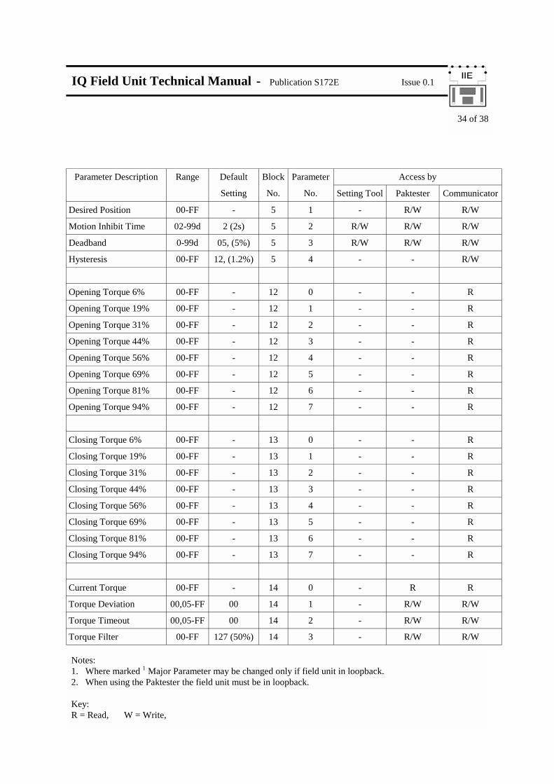
34 of 38
Notes: 1. Where marked 1 Major Parameter may be changed only if field unit in loopback. 2. When using the Paktester the field unit must be in loopback. Key: R = Read, W = Write,
Parameter Description Range Default Block Parameter
Setting No. No. Setting Tool Paktester Communicator
Desired Position 00-FF - 5 1 - R/W R/W
Motion Inhibit Time 02-99d 2 (2s) 5 2 R/W R/W R/W
Deadband 0-99d 05, (5%) 5 3 R/W R/W R/W
Hysteresis 00-FF 12, (1.2%) 5 4 - - R/W
Opening Torque 6% 00-FF - 12 0 - - R
Opening Torque 19% 00-FF - 12 1 - - R
Opening Torque 31% 00-FF - 12 2 - - R
Opening Torque 44% 00-FF - 12 3 - - R
Opening Torque 56% 00-FF - 12 4 - - R
Opening Torque 69% 00-FF - 12 5 - - R
Opening Torque 81% 00-FF - 12 6 - - R
Opening Torque 94% 00-FF - 12 7 - - R
Closing Torque 6% 00-FF - 13 0 - - R
Closing Torque 19% 00-FF - 13 1 - - R
Closing Torque 31% 00-FF - 13 2 - - R
Closing Torque 44% 00-FF - 13 3 - - R
Closing Torque 56% 00-FF - 13 4 - - R
Closing Torque 69% 00-FF - 13 5 - - R
Closing Torque 81% 00-FF - 13 6 - - R
Closing Torque 94% 00-FF - 13 7 - - R
Current Torque 00-FF - 14 0 - R R
Torque Deviation 00,05-FF 00 14 1 - R/W R/W
Torque Timeout 00,05-FF 00 14 2 - R/W R/W
Torque Filter 00-FF 127 (50%) 14 3 - R/W R/W
Access by

IQ Field Unit Technical Manual - Publication S172E Issue 0.1
35 of 38

IQ Field Unit Technical Manual - Publication S172E Issue 0.1
36 of 38

IQ Field Unit Technical Manual - Publication S172E Issue 0.1
37 of 38
AUX 1
AUX 2
AUX 3
AUX 4 ESD
CLOSE
OPEN
LEVEL SWITCH
0V DC SUPPLY 4
24V DC SUPPLY
T/STAT BYPASS - ESD
CLOSE
STOP / MAINTAIN
OPEN
COMMON -VE 20-60V AC/DC
5
25
33
34
35
36
ACTUATOR EXTERNAL CONNECTIONS
Remote Auxiliary Input Mask set to: 1 0 1 1 1 1 1 1: = B F
Typical External Connection Diagram

IQ Field Unit Technical Manual - Publication S172E Issue 0.1
38 of 38
Rotork Controls Ltd Rotork Controls Inc Bath, England 19, Jet View Drive BA1 3JQ Rochester tel: (0225) 428451 New York 14624 fax: (0225) 333467 USA tel: (716) 328 1550 fax: (716) 328 5848