
Applications of Fiber Optic Coupled-Grazing Angle Probe Reflection-Absorption FTIR Spectroscopy

REPORT SSD-TR-90-29 L'
SA •. - ;EROSPACE REPORT NO.
AD-A230 183
Degenerate Four-Wave Mixing of CW HF Laser Bear sin HF Absorption Cell
Prepared by
H. MIRELS, J. G. COFFER, J. M. BERNARD, and R. A. CHODZKOAerophysics LaboratoryLaboratory Operations
DTIC..-:' '-- ,E.,ZTEDEC 20 1990 6 August 1990
Prepared for
SPACE SYSTEMS DIVSIONAIR FORCE SYSTEMS COMMAND
Los Angeles Air Force BaseRO. Box 92960
Los Angeles, CA 90009-2960
Development Group
THE AEROSPACE CORPORATION,-'El Segundo, California
APPROVED FOR PUBUC RELEASE;DISTRIBUTION UNUMITED

This report was submitted by The Aerospace Corporation, El Segundo, CA90245-4691, under Contract No. F04701-88-C-0089 with the Space Systems Division, P 0.Box 9296, Los Angeles, CA 90009-2960. It was reviewed and approved for The AerospaceCorporation by R. W Fillers, Director, Aerophysics Laboratory. Captain Rafael Rivierewas the Air Force project officer for the Mission-Oriented Investigation and Experimenta-tion (MOTE) program.
This report has been reviewed by the Public Affairs Office (PAS) and is releasable tothe National Technical Information Service (NTIS). At NTIS, it will be available to the gen-eral public, including foreign nationals.
This technical report has been reviewed and is approved for publication. Publicationof this report does not constitute Ai" Force approval of lihe report's findings or conclusions.It is published only for the exchange and stimulation of ideas.
,
RAIfAEL RIVIERE, CAPT USAF JQATHAN M. EMMES, MAJ, USAFMOlE Project Officer MOlE Program ManagerSSD/CNL AFSTC/WCO OL-AB

UNCLASSIFIEDSECURITY CLASSIFICATION OF THIS PAGE
REPORT DOCUMENTATION PAGE
la REPOR1 SECURITY CLASSIFICATION lb RESTRICTIVE MARKINGS
Unclassified2a SECURITY CLASSIFICATION AUTHORITY 3 DISTRIBUTION/AVAILABILITY OF REPORT
Approved for public release;2t DECLASSIFICATIONOOWNGRADING SCHEDULE distribution is unlimited.
4 PERFORMING ORGANIZATION REPORT NUMBER(S) 5. MONITORING ORGANIZATION REPORT NUMBERIS)
TR-(X)89(4930-06)-3 SSD-TR-90-29
6a. NAME OF PERFORMING ORGANIZATION 5b OFFICE SYMBOL 7a NAME OF MONITORING ORGANIZATIONThe Aerospace Corporation (if applicable)
Laboratory Operations Space Systems Division
6c ADDRESS (City State, and ZIP Code) 7b ADDRESS (City State, and ZIP Code)
El Segundo, CA 90245-4691 Los Angeles, Air Force BaseLos Angeles, CA 90009-2960
8a NAME r; FUN17NG,,SPONSORNC 8b OFFICE SYMBOL 9 PROCUREMENT INSTRUMENT IDENTIFICATION NUMBERORGANIZATION (If applicable) F04701-88-C-089
8c ADDRESS (City State. and ZIP Code) 10 SOURCE OF FUNDING NUMBERSPROGRAM PROJECT TASK WORK UNITELEMENT NO NO. NO ACCESSION NO
11 TITLE (Include Security Classification)
DEGENERATE FOUR-WAVE MIXING OF CW HF LASER BEAMS IN HF ABSORPTION CELL
12 PERSONAL AUTHOR(S) Mirels, Harold; Coffer, John G.; Bernard. Jay M.; and Chodzko, Richard A.
13a TYPE OF REPORT 13b TIME COVERED 14. DATE OF REPORT fYea, Month, Day) 15 PAGE COUNT
FROM TO 1990 August 6 4716 SUPPLEMENTARY NOTATION
17 COSATI CODES 18 %3. JECT TERMS (Continue on reverse if necessary and identify by block number)
FIELD GROUP SUB-GROUP cw'hydrogen fluoride laser Degenerate four-wave mixing
I IF1ABTATNonlinear ohaetics.gaio
19 ABSTRACT (Continue on reverse if necessary and identify by block number)Phase conjugation of a cw hydrogen fluoride (HF) laser beam has been investigated experimentally andtheoretically using resonant degenerate four-wave mixing (DFWM) in an HF gas absorption cell. A single-line single-mode HF laser. operating on 1;(8), P1(9), or Pl(10transitions, provided total (forward plusbackward) pump beam intensities of 130, (0, and 400 W/,gm respectively, in the HF absorption cel. Aprobe beam intensity of the order of 10 W/O't was also provided. Conjugate reflection of the probe beamwas investigated as a function of gas cell pressure and as a function of frequency detuning from line center.The variation of reflectivity with gas cell pressure at fixed laser beam intensity indicated a peak reflectivityof the order of &,-4 at pressures from 2 to 4 Torr. Measurement of conjugate beam intensity, as a functionof frequency detuning from line center, provided a signal with a full width at half maximum (FWHM) ofabout 30 MHz. The latter is of the order of the homogeneous width, for HF at the test pressure, and maybe compared to the Doppler width i(a = 300 MHz for the medium. An analytical model is presentedwhich provides theoretical estimate. for the variation of reflectivity with pressure. Effects of diffusion, ther-mal conduction, pump depletion, a rid a nonuniform (Gaussian) profile are considered. Theoretical esti-mates for peak reflectivity a wit experiments to within a factor of about 2.
20 DISTRIBUTION/AVAILABILITY OF ABSTRACT , 21 ABSTRACT SECURITY CLASSIFICATION
UNCLASSIFIED/UNLIMITED [] SAME AS IAPT [] DTIC USERS Unclassified
22a NAME OF RESPONSIBLE INDIVIDUAL 22b TELEPHONE (Include Area Code) 22c OFFICE SYMBOL
DD FORM 1473, 84 MAR 83 APR edition may be used until exhausted SECURITY CLASSIFICATION OF THIS PAGE
All oth ertioe a, obsolete UNCLASSIFIED
r f

CONTENTS
I. INTRODUCTION ...................................................... 5
1I . THEORY ............................................................ 7
A. Homogeneous Medium ............................................ 8
B. Inhomogeneous Medium .......................................... 11
C. Pressure Variation Effect in Limit 62 << 1 .................... 12
D. Pump Depletion ................................................ 17
E. Gaussian Profile .............................................. 17
F. Thermal Grating ............................................... 19
III. EXPERIMENTAL APPARATUS AND PROCEDURE .............................. 21
IV. EXPERIMENTAL RESULTS .............................................. 25
A. Detuning Effect ............................................... 25
B. Pressure Variation Effect ..................................... 26
V. CONCLUDING REMARKS ................................................ 31
REFERENCES ............................................................. 33
APPENDIXES ............................................................. A-I
A. SYMBOLS ....................................................... A-I
B. MOLECULAR DATA FOR HF ......................................... B-I
C. DEGENERATE FOUR-WAVE MIXING THEORY ............................ C-I
D. DIFFUSION EFFECT .............................................. D-I
E. THERMAL GRATING .............................. ................ E-I
j Usti f cl tin-------------
/KC I -- - -- .
1 i;jOtlgd IJ I.Y ... .. . ..... ... ..
\. b , :6:,
fI

FIGURES
1. Geometry for DFWM ................................................. 7
2. Grating Formation and Readout in DFWM ............................. 8
3. Variation of Reflectivity with Intensity .......................... 10
•4. Variatio-i of Reflectivity witli Detuning 6 at Fixed It/I ......... 10t s......
5. Variation of Line Center Reflectivity with Pressure ............... 15
6. Comparison of Line Center Reflectivities As ociated with Uniform
and with Gaussian Beam Profiles in Limits a0 L << 1 ................ 20
7. Experimental Apparatus ............................................ 22
8. Effect of Detuning on Conjugate Signal Intensity .................. 25
9. Variation of Line Center Reflectivity with Pressure forFixed Average Intensity It ........................................ 26
TABLES
1. Absorption Coefficient and Saturation Intensity for HF PI(J)Transitions ....................................................... 13
2. Maxima Associated with Variation of Reflectivity with Pressurefor Inhomogeneously Broadened Medium .............................. 16
3. Comparison of Theory and Experiment for pm and (RD)m,p ............ 29

I. INTRODUCTION
Phase conjugation of a cw HF chemical laser beam is of interest for
aberration correction in systems that employ these lasers. Studies of
phase conjulgation of an HF chemical laser beam by means of stimulaLed
Briliouin scattering (SBS) are reported in Refs. 1 and 2. A difficulty
with the SBS approach to HF laser phase conjugation is the need for
megawatt power levels in order to achieve threshold.3 In addition, the
frequency of the conjugate beam is Doppler shifted from the incident
beam. These limitations can be circumvented by employing degenerate four-
wave mixing (DFWM) (e.g., Refs. 4-7). A theoretical study of the
application of DFWM for phase conjugation of a pulsed, multiline HF
chemical laser by use of a homogeneously broadened saturable gain medium is
reported in Ref. 8.
The use of DFWM for phase conjugation of a cw HF chemical laser beam
is investigated analytically and experimentally in this report. Analytic
expressions are deduced for DFWM reflection coefficients associated with a
saturable absorber. Effects of diffusion, heat conduction, pump depletion,
and a Gaussian profile are considered. The experimental study employs a
single-line, single-longitudinal mode ow HF laser operating at 1-10 W and a
gaseous HF absorption cell operating at nominal pressures of 1-10 Torr.
Experimental values of reflection coefficient are reported as a function of
frequency detuning from line center and absorption cell pressure.
Symbols are defined in Appendix A. Spectroscopic and chemical rate
data for HF are given in Appendix B.
5

II. THEORY
The DFWM process is illustrated in Fig. 1. Here, If I b , Ip and Ic
denote the intensity of the forward pump, backward pump, probe, and
conjugate vas, rcspect-ively. The waves are assumed to have the same
frequency and to interact in a saturable medium. The forward and backward
pump waves are required to be phase conjugates. This is easily achieved by
the use of counter-propagating plane waves from a single laser source. The
angle between I and If is denoted 8 and is assumed small in this study.
p If
If I k
-NONLIN
EAR
MEDIUM
P L
Fig. 1. Geometry for DFWM.
The physical basis for the generation of Ic is illustrated in Fig.
2. The interaction between waves Ip and If creates a stationary sinusoidal
interference pattern of wavelength X = A/[2 sin(0/2)] which interactsPfwith the saturable medium to form a sinusoidal variation in medium
susceptibility. The latter scatters the incident beam Ib to form Ic , which
can be shown to be the phase conjugate of Ip. Similarly, Ip and Ib form a
grating of wavelength A = /[2 cos(6/2)] which scatters If to add
7

xpt = X/[2 sin(0l2)]
0 0 0
-lhtXpb X/[2 cos(0/2)] I
Ip .P b Ic
(a) FORMATION (b) READOUT
Fig. 2. Grating Formation and Readout in D.M.
coherently to the phase conjugate I c . For small 6, the gratings XAf and
Apb are termed "wide" and "narrow," respectively.
In the following sections, we sumarize expressions for the reflectiv-
ity R - Ic/I p for both homogeneously and inhomogeneously broadened
saturable media. To simplify the expressions, we assume If = I b , Ip, e <<
and 02 << I. Beam intensity is assumed to be uniform in the tran -
verse direction. The effects of a Gaussian intensity profile, diffusion,
heat conduction, and pump depletion are also considered.
A. HOMOGENEOUS MEDIUM
Reflectivity expressions for a homogeneously broadened saturable
,in the limit pc << fb and 62 << I, are given in Appendix C.
Whten pump depletion effects are negligible and If = I b , the reflectivity
is, from Eq. (C-9b),

62) R - (It/Is)2 [1 + O(aEL)])(1)
(cEL)2 [1 + 2(It/I)] 3
where a term of order aL is neglected and
it f if + Ib (2a)
I = I0(1 + 62) (2b)
6 = (V-VO)/(AVh/2) (2c)
Here, Is is a suitable line center (6 = 0) saturation intensity, Av is the5 hhomogeneous width, u is the length over which the four waves interact,
Eand O is the line center small-signal electric-field absorption
0 Ecoefficient. Expressions for Is , a0 and Avh are given in Appendix B. The
variation of (1 + 6 2)R/(a L)2 with It/Is is indicated in Fig. 3. The
reflectivity has a maximum value given by
27(0 + 62) Rm 'I = 1 (3)(aEL)
2
which occurs at an intensity
It/ s = 1 (4)ts
The variation of R/(ctEL)2 with the detuning parameter 6, for fixed00
It/I , sis indicated in Fig. 4. For each curve, the intensity is a maximum
at 6 = 0. The half width at half maximum (HWHM) of these curves equals
0.51 in the limit It/1 0 0 and increases with increase in It/I.
9

1.0
"0.8 -
'Cj
>: 0.4-
uj0.2U-j
01 2 3 4 5INTENSITY, It/Is
Fig. 3.Variation of Reflectivity with Intensity.
Eq. (1), Et0L (K 1.
1.0 1 1
0.9- 4 .0
0.4,
LU
0.1
*0 0.2 0.4 0.6 0.8 1.0 1.2 1.4 1.6 1.8 2.0
DETUNING, 6
Fig. It. Variation of Reflectivity with Detuning 6 at Fixed
1/0. E
10
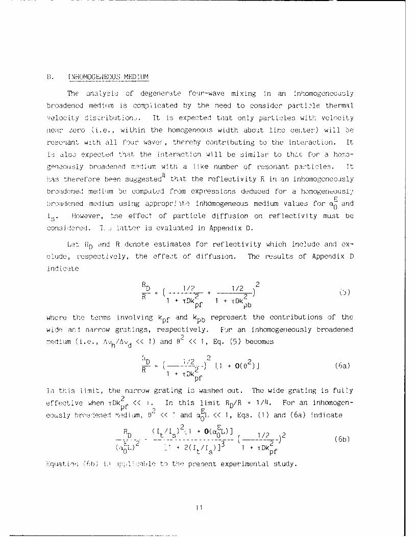
B. INHOMOGEAEOUS MEDIUM
The anatysis of degenerate four-wave mixing in an inhomogeneously
broadened medium is complicated by the need to consider particle thermal
velocity dis-ribution-,. It is expected that only particles with velocity
near zero (i.e., within the homogeneous width abost line cer.ter) will be
resonant with all rour wave.-, thereby contributing to the interaction. It
is also expected that the interaction will be similar to thar. for a homo-
gen ously broadened medium with a like number of resonant particles. It
has therefore been suggested 4 that the reflectivity R in an inhomogeneously
broadened mediuim be computed from expressions deduced for a homogenously
broadened medium using appropri ite inhomogeneous medium values for .0 and
is . However, the effect of particle diffusion on reflectivity must be
considered. 'I. - latter is evaluated in Appendix D.
Let RD and R denote estimates for reflectivity which include and ex-
clude, respectively, the effect of diffusion. The results of Appendix D
ind icate
R2 2D 112 + 112 ](:s
I + -rDk 1 + TDkpf Ipb
where the terms involving kpf and kpb represent the contributions of the
wide and narrow gratings, respectively. For an inhomogeneously broadened
medium (i.e., Av h/Av d << 1) and 02 << 1, Eq. (5) becomes
D -1 + 0()2 (6a)
1 + tDk pf
In this limit, the narrow grating is washed out. The wide grating is fully
effective when TDk 2 << I. In this limit RD/R = 1/4. For an inhomogen-pf E
eously broadened medium, 0'- << and a0L << 1, Eqs. (1) and (6a) 'ndicate
R (It/12 i + o(aEL)]. ...- 1 12)] 1 2 (6b)
E 2 [1 2I/) 3 1 2 ~( 0 L)I + Dkpf
Equiat ion (6b) i: mpi i cable to the present experimental study.
11

C. PRE SSRE S VA, IA&' LON LI'FECT IN LIMIT 62 << 1
The variation of reflectivity with cell pressure is of interEst. We
issum,. I- << I. For the present ca-c of a hydrogen fluoride gas at
prossires- oF order 110 Torr, the pressure dependence of 0 arid I can be
ex~rcss:-as
A = p a (7a)
o a2
0 -S'3 K P'- (Tb)
::.,v r~o~cs -o11 pres:re. Theoretical estimates for k and ks are
de. in Appen(ijv B and are listed in Table 1. We write Is/it and u"L inst 0the form
lol =4(plci) (8a)
EL c(p/e (8b)c0
2' t 1/2(8c)
c = k L1 (8d)c1
Sustitstion into Eq. (6b) yields, for 62 << 1,
216R D 27(p/c1 )8 L1 + O(c)]
- -- 2---2- (9a)c [2(p/c 1 ) 2-+ 1]3 L(P/C 1 )2 + B]2
where B is independnt of pressure and is given by
B -p 2 D k /Cl2 (9b)pf 1
12

Table 1. Absorption Coefficient and Sat ration Int-nskty for
HF PI(J) Transitions. k = /p, k I /pax 0 s 3
T J k 3
(K) W
(cm-Torr)
300 7 0.07943 78.52
300 8 0.01897 74.60
300 9 0.00364 71.14
300 10 0.00056 68.03
400 7 0.15308 52.49
400 8 0.05643 49.87
400 9 0.01702 47.55
400 10 0.00436 45.47
500 7 0.21055 38.40
500 8 0.09567 36.49
500 9 0.03786 34.79
500 10 0.01310 33.27
600 7 0.23437 29.75
600 8 0.12508 28.27
600 9 0.05932 26.96
600 10 0.02509 25.78
13

Equation (9a) provid&.3 the variation of RD with pressure and is plotted in
Fig. 5a. The reflectivity RD has a maximum at
p 2 2 1/2(-1h) = (1/2)[1 + B + (1 + lOB + B2) / ] (10a)
whicn, for small and large B, becomes, respectively,
(Pm/ci = 1 + 3B - 6 32 + O(B3 ) (lOb)
= B11 + (3/B) + 0(1/B 2 )] (10c)
The reflectivity maximum is denoted (RD)m, p and is obtained by substitution
of Eq. (10) into Eq. (9). For small and large B,
216 (RD)m ,p . I - 2B + O (B2 ) (11a)
2C
27 B + 0(-I)] (11b)3--2B 2B-B
Equations (8a) and (lob) indicate that at the maximum point, 1/1 0
(1/4)[1 + O(B)]. This result differs from Eq. (3b) due to the variation
of E with p.
Corresponding values of B, pm/cl, (RD)m,p/c2 and (TDk2f =
m2 pfB/(pm/c1) 2 are given in Table 2. These permit theoretical estimates of pm
and (RD)m,p for given values of It , ka, ks , and L. Conversely, c,
ci, k and k- can be deduced from experimental observation of pm and
(RD)m,p for given I. and L. The procedure is most accurate when B << 1.
14

1.0-
B = 0.0
CNJ(J 0.8 --0.2cc- 0.5 c << 1
c 0.6
o..0~0.4-LLJ
LU0.2-
0.00 2 4
PRESSURE, p/c1
(a)
1.0-c = 0.01
* 0.8 0.1- -0.2
.-00.3
0.00
0 .4 -' .Lu
LM"0.2-
0.0 1.0 2.0 3.0 4.0 5.0
PRESSURE, p/c1(b)
Fig. 5. Variation of Line Center Reflectivity with Pressure. (a) Effect ofdiffusion for case where narrow grating is fully washed out and c<< 1, Eq. (9). (b) Effect of pump depletion for case wherediffusion effects are negligible. The degree of pump depletion ischaracterized by the value of the parameter c. Appendix C.
15

Table 2. Maxima Associated with Variation of Reflectivity with Pressurefor Inhomo3geneou,'sly ' Broadened Medium and lf(O) = Ib(L), Ip, C
I f,, , - << 1, - << 1.
(a) Eft'ect of Diffusion As:iuming Negligible Pump Depletion(c<I) and Complete Narrow Grating Washout (t Dkpb >> 1).See Eqs. (9) and (10) and Fig. 5a.
PM C'Pm 16(R D) m, p (rDk 2.m?13(
c2 ft~ ~mcl p
0.000 1.000 1.000 0.0000.100 1.122 0.844 0.0790.200 I.213 0.739 0.1360.300 1.289 0.662 0.1810.400 1.355 o.602 0.2180.500 1.414 0.553 0.2500.600 1.468 0.512 0.278
0.700 1.519 0.478 0.3030.800 1.566 0.448 0.3260.900 1.611 0.423 0.3471.000 1.653 0.400 0.3662.000 2.000 0.263 0.5003.000 2.272 0.198 0.5814.000 2.505 0.159 0.6375.000 2.713 0.133 0.6796.000 2.902 0.115 0.7127.000 3.079 0.101 0.7398.000 3.244 0.090 0.7609.000 3.400 0.081 0.77910.000 3.548 0.074 0.794
(b) Effect or Pump Depletion Assuming Negligible Diffusion.
See Appendix C and Fig. 5b.
Pm 54R , p
0.000 1.000 1.000
0.010 0.985 0.9800.100 0.878 0.8300.200 0.799 0.7110.300 0.7142 0.6230.500 0.662 0.14970.600 0.632 O.4511.000 0.547 0.3253.00() 0.380 0.121
16

In this limit
c = [216(RD ) mp]1/2 (12a)
c1 = Pm (12b)
k [216 (RD ) mp]1 2 /(p mL) (12c)
ks sks = 41t/P 2 (12d)
D. PUMP DEPLETION
In the previous sections it was assumed that the pump beam intensity
did not vary along the optical path. This assumption is consistent with
the assumption ctEL << 1. With increase in aEL, pump depletion, due to
absorption, must be considered. A computation procedure which incorporates
pump depletion is outlined in Appendix C. The variation of reflectivity
with pressure, at fixed-incident pump beam intensity, is indicated in Fig.
5b. Diffusion and detuning effects are neglected. The magnitude of the
pump depletion effect is characterized by the parameter c, which is relatedto aEL. Pump depletion is seen to reduce 54 / 2 and Pm/C. These
maxima are tabulated versus c in Table 2b.
E. GAUSSIAN PROFILE
It has been assumed that each of the beams participating in the DFWM
process has a uniform intensity profile. We now assume that each beam has
a Gaussian profile with a beam waist w. Reflectivity is estimated. We
assume a homogeneously broadened medium and neglect diffusion and detuning.
The Gaussian profiles are expressed
Ic Ip I t -2 (r/w)2
-= P - - =e (13)Ic,O Ip,O It,O
17

where r is the transverse radius, and subscript zero denotes the centerline
value. Let Pt-= Pf + Pb denote the net pump beam power. The latter is
related to It, 0 by
P t I t 'ot t2 (14a)2 2
1TW
I t (14b)
Equation (14b) defines an average net pump intensity denoted I We now
assume that the grating wavelengths Apf and Xpb are small compared with
w. The DFWM process at each radius r may then be assumed to be the same as
that for corresponding uniform beams. The average reflection
coefficient R is then
p f RIpr dr- 0R - (15)
P f I r dr0 p
which can be evaluated using Eq. (1) and Eq. (13). For 62 << 1, the result
can be expressed in the forms
=1 [In(I + 4a) 48(I+68)] (16a)(E L)2 =
_____ '4(+8)0
R 1 [in(1+4) 4 2(+60)i (16b)c 2 64B 2 (1+40)2
where I 2I t c1a 1 (16c)
Equation (16a) gives the variation of R with It at constant p, while Eq.
(16b) gives the variation of R with p at constant It" These may be
compared with the corresponding expressions for a uniform intensity
profile, namely
18

R 3 (17a)(aL)2 1 + 2) 3
andR (17b)c (1 + 26)
where = It/Is* Equations (16) and (17) are plotted in Fig. 6. Equations
(16a) and (16b) have maxima at
27R m27m - = 0.8278 (18a)(a EL) 2
I = 1.106 (18b)
and
54 = - 0.9412 (19a)2
C
Pm/Cl 1.147 (19b)
The right-hand sides of Eqs. (18) and (19) equal I for the corresponding
case of a uniform profile. Thus, the difference between the uniform and
Gaussian beam is relatively small (i.e., of the order of 10 to 20% in the
vicinity of the maximum reflectivity point), provided It is evaluated in
accord with Eq. (14). The symbols RD and RD are used interchangeably in
subsequent sect ions.
F. THERMAL GRATING
Thermal gratings are discussed in Appendix E. It is concluded that
thermal grating effects are negligible in the present study. However, the
increase in mean temperature along the optical axis, due to energy
absorption, affects mean fluid properties such as k and ks (e.g., Table 1)
and thereby affects reflectivity.
19

1.0 -I0UNIFORM PROFILE (R vs I /Is)'
S0.8- "' .8 I" " /GAUSSIAN PROFILE-
0.6
S0.4LUIU-LU 0.2
I0.00 2 4 6 8
(a).o-~~ -_,/ 0
cli 0.8- GAUSSIAN PROFILE
0 '"UNIFORM PROFILE- 0.6
i0.4LU
LU
0.2
0.00 1 2 3 4
PRESSURE, p/c1(b)
Fig. 6. Comparison of Line Center Reflectivities associated with Uniformand with Gaussian Beam Profiles in Limit a0 L << 1. (a) Reflectiv-ity versus intensity. (b) Reflectivity versus pressure.
20

Il[. EXPERIMENTAL APPARATUS AND PROCEDURE
A diagram of the apparatus used in the present experiment is shown in
Fig. 7. A low-power single-line cw HF laser provided two counter-propagat-
ing pump beams and an off-axis probe beam within a 10-cm-long HF absorption
cell. The HF laser had a stable cavity which produced a TEMoo Gaussian
beam in a single longitudinal mode. Power levels up to about 10 W were
obtained on P1 (8), PI(9), and P1 (10) transitions. The Gaussian beam was
focused with a concave mirror (MI) such that the forward pump beam, the
backward pump beam, and the probe beam were all simultaneously focused in
the center of the absorption cell. The interaction distance for the three
beams was greater than the 10-cm absorption cell length. The angle between
the probe beam and the forward pump was approximately I deg to provide good
overlap of the beams and avoid washout of the wide grating. The Gaussian
beam waist (radius) in the cell was 0.55 mm. The phase conjugate return
signal was measured with detector D1, a LN2-cooled HgCdTe detector.
The concave mirror of the HF laser stable-resonator was mounted on a
piezoelectric-driven translation stage (Burleigh Inch Worm) so that the
laser frequency for each PI(J) transition could be adjusted by varying the
cavity length. During the phase conjugation reflectivity measurements, the
frequency of the laser was continuously varied over a 300-MHz range using
the Inch Worm driver. The 300-MHz range corresponds to the free spectral
range of the resonator cavity and is approximately equal to the Doppler
width of the HF absorption line at 300 K. Laser frequency was monitored
with a scanning confocal interferometer using the 1% reflected beam from
beamsplitter BS 0.
A chopper was used on the probe beam so that a lock-in amplifier could
discriminate the small reflected-conjugate signal from scattered cw light
and other noise sources. Beam blocks were inserted in the optical path of
the probe and pump beams to verify that the observed signal was produced by
the interaction of all three beams within the absorbing HF medium. A
removable retroreflector and some removable neutral-density filters were
21

L
0 _w - - -- _ _
LWINDOW CL d WINDOWGAUSSIANPROFILE(all beams) L = 10 cm PHF = 1 - 10 Torr
d = 1.0cm T = 3000 Kw = 0.55 mm0 = 0.017 rad
(a) CELL GEOMETRY
DiCOOLED Fr-"HgCdTe TO0DETECTOR COPR LOCK-IN
REMOVABLE_ . r BEAM AMPLIFIER DIGITALFII TERS *. DUMP OSCILLOSCOPE
PHASECONJUGATE
S 2/-PROBE
CHOPPER --- - - BEAM
S 3 ABSORPTION REMOV,,,, REMOVABLE
CELL PSEUDO-
v A HF GAS CONJUGATE
CONFOCAL TO RETROREFLECTOR
HeNe LASER 0 INTERFEROMETER VACUUM
DETECTO Vi ]PZT LENGTH L H 0
ADJUSTMENT OSCILLOSCOPE
SINGLELINE,SINGLE FREQUENCY (b) ARRANGEMENT
CW HF LASER
Fig. 7. Experimental Apparatus. (a) Cell geometry, (b) Arrangement.
22

used to position the detector at the location of the conjugate return beam,
to calibrate the reflectivity measurement, and to establish reflected
signal-to-noise ratio. Signal-to-noise ratios as high as 60 were
measured. The ratio of reflected signal on line-center to background off
line-center was usually about 5 to 1. In most cases, the difference
between these two signals was used to evaluate the reflected signal when
calculating conjugate reflectivity.
23

IV. EXPERIMENTAL RESULTS
A. DETUNING EFFECT
The variation of conjugate intensity with detuning v-v0 .3 indicated
in Fig. 8. For the present case, the Doppler and homogeneous widths are
Ad 300 - 106 Hz and A h X 106 Hz, respectively. It is seen that
the FWHM (full width at half maximum) of the conjugate signal is of' the
order of Avh. This is expected from physical reasoning because only
particles within the frequency range Avh about line center are resonant
with the three input beams If, Ib , and Ip. These results also support the
present use of a homogeneous theory (with appropriate absorption and
saturation coefficients) to model DFWM in an inhomogeneously broadened
medium.
LLJ
CDI.O
= ,UCD
L_
C/ L 3.0 -
-150 0 +150
-150 0 +150
LASER FREQUENCY DEVIATIONFROM LINE CENTER, MHz
Fig. 8. Effect of Detuning on Conjugate Signal Intensity.
25

B. PRESSURE VARIATION EFFECT
The variation of line Center (6 0 O) reflection coefficient RD with
pressure p is given in Fig. 9 for three transitions P1(8), P1 (9), and
P1 (10) with pump intensities It = 130, CO0, and 400 W/cm2 , respectively.
The maximum reflectivity (RD)ip is of the order of 10- 4 and occurs at
pressures pm from 2 to 4 Torr. The experimental values of (RD)m,p and pm,
deduced from Figs. 9a to 9c, are listed in Table 3c.
Figure 9 include theoretical estimates for the variation of RD with
p. Thesc were obtained using Eq. (9a) with an analytical estimate f-r B
and 4ith arbitrary choices for c and c I . The latter were chosen so that
the experimental and theoretical curves were in agreement at the maximum
point. The shapes of the theoretical and experimental curves are in
approlximat- agreement.
I XPLRIMENIAL DAIA
J=8L]CI - 130 Wlcm
2
X Pm = 16 fou
2 -- 1'4 x (0D6.p 25 -
>_-
/-THEORY, [E (9a)El 0241c = 0277uC-) I=
Lij c 128
,W, 0al:
00 1 2 3 4 5 6
CELL PRESSURE p, Torr(a)
Fig. 9. Variation of Line Center Reflectivity with Cell Pressure for FixedAverage Intensity I Experimental data denoted by squares.
t.Theoretical curves are based on Eq. (9a) using values of c and c I
chosen to match experimental values of [Rn) and pm. (a) Tran-sition P1(8), intensity I t = 130 W/cl . "b5 Transition PI(),intensit I = 600 W/cm . (c) Transition P1 (10), intensity It =400 W/cm
26

5 XF'[RIM[NIAL DATA
CcC
CD E0 20
oc1 2 4 5 36
CELPESUEpIrL(b)
1 _. 0 0X[TET[DT
J = TO
1= 400 Wjcmn2
pm =3 5 Torr
~1.2 THEORY. [0 (9a)
cc: 0
0.010 1 2 3 4 5 6
CELL PRESSURE P, Torr(c)
Fig. 9 (ccncluded)
27

Tanle 3 represents an attempt to compute (RD)m,p and pm from purely
analytical considerations. Table 3a contains estimates for k , ks , C, C1
and B. The latter are based on a temperature T = 300 K and thereby neglect
laser heating. The estimates for (RD)mp and pm in Table 3a are based on
Eq. (9a) and take diffusion into account. Table 3b corrects these
estimates for Gaissian profile and pump depletion effects. The correed
theory in Table 3b agrees with the experiment to within a factor of about
2, except for the value of (RD)m,p for the case J = 10. The poor agreement
for this case is probably due to the present neglect of the induced
temperature rise. (Note, from Table 1 , that the variation of k with T is
greatest for the J = 10 case.)
Tnermocouple measurements near the optical axis indicate temperature
increases of the order 50-100 K due to absorption of laser radiation. The
latter measurements were made by R. M. Kurtz. Further study is needed of
the magnitude of the temperature rise and its effect on reflectivity.
28

a E
Q) - ?-)CE I (\ I L
oc Nx) N t,- c\00
CN m
Q)
CC)Q N f -0-
m CL (a. C AJ
C)Qo LC l
C) -. C 'J C
0 ~ C 0.C ~ C) -
C'D tI a) 000
0 cj " C a
C)) -Lr)
C) -j
Q)) -4 E Lr t-E-1*~~~~1 -C~>, 0 0-'0j.
--T 0~--C C-1 C;CIL 0 0N n
C) 4-- Q0) mx. R'Z -0 C
rt' Q ) 03'oI~ ~00 >)OC) C) CjC -
.0 '- 0 CIO CTW-C--~~~~~ CD 00C -. 'ir)~C
U) w 0 4- -- -r . 04A-) C) C)
>10 0 U) LC ) E0* 70%
0- 0\ C)C) cD,0o C 0' LC)
(D'I ~ ~ ~ ~ ~ U 0k ) 0 0 C E ~ tlL C
00- r100 0) 01) 0 C

V. CONCLUDING REMARKS
The present study may be viewed as a first attempt to investigate
phase conjugation of a cw HF laser beam by use of an HF absorption cell.
Emphasis has been placed on the variation of reflectivity with pressure.
The theoretical development included consideration of diffusion, thermal
conduction, pump depletior and Gaussian profile effects. Further study is
needed, particularly with regard to temperature effects and conjugation
fidelity.
31

REFERENCES
1. Duignan, M. T., Feldman, B. J., Gibson, N. D., and Whitney, W. T.,"Stimulated Brillouin Scattering of Multiline Hydrogen Fluoride LaserRadiation," SPIE Vol 874, 1988, p. 25.
2. Koop, C. G., "Stimulated Brillouin Scattering at 2.9 t," Inter-national Conference on Lasers '88, Harvey's Resort Hotel, Lake Tahoe,Nevada, December 4-9, 1988.
3. Shen, Y. R., The Principles of NoiiLnear Optics, John Wiley & Sons,1984, pp. 187-192.
4. Abrams, R. L. et al., "Phase Conjugation and High-Resolution Spectros-copy by Resonant Degenerate Four-Wave Mixing," in R. A. Fisher, Opti-cal Phase Conjugation, Academic Press, 1983, pp. 211-284.
5. Eaintjes, J. F., Nonlinear Optical Parametric Processes in Liquids andGases, Academic Press, 1984, pp. 377-392.
6. Brown, W. P., "Absorption and Depletion Effects on Degenerate Four-Wave Mixing in Inhomogeneously Broadened Absorbers," J. Opt. Soc. Am.,Vol. 73, No. 5, May 1983, pp. 629-634.
7. Gruneisen, M. T., Gaeta, A. L., and Boyd, R. W., "Exact Theory ofPump-Wave Propagation and its Effect on Degenerate Four-Wave Mixing inSaturable-Absorbing Media," J. Opt. Soc. Am. B, Vol. 2, No. 7, July1985, pp. 1117-1121.
8. Galushkin, M. G., Nikitin V. Yu, and Oraevskii, A. N., "Phase Conjuga-tion of an Optical Wave in the Case of Degenerate Four-Wave Inter-action in an Amplifying Medium of a Chemical HF Laser," Soy. J.Quantum Electron. 18 '1), January 1988, p. 87.
9. Mire! , H., "Inhomogeneous iroacening Effects in cw Chemical Lasers,"AIAA J., Vol. 17, No. 5, May 1979, p. 478.
10. Mirels, H., "Effects of Translational and Rotational Nonequilibrium oncw Chemical Laser Performance," Appl. Opt., Vol. 27, No. 1, 1 January1988, p. 89.
11. Svehla, R. A., "Estimated Viscosities and Thermal Conductivities ofGases at High Temperatures," NASA Technical Report, R-132, 1962.
12. Zel'dovich, B. Ya., Pilipetsky, N. F., and Shkunov, V.V., "Principlesof Phase Conjugation," Springer-Verlag, Berlin, 1985, pp. 176-184.
33

13. Caro, R. G., and Gower, M. C., "Phase Conjugation by Degenerate FourWave Mixing in Absorbing Media," IEEE J. Quantum Electron., Vol. QE-18, No. 9, September 1987, p. 1376.
34

APPENDIX A
SYMBOLS
B parameter characterizing diffusion effect, Eq. (9b)
c k Lc1
ci 2(1 t/k )/2
D diffusion coefficient Eq. (D-i)
k wave number of incident waves
kij wave number associated with Ei + c. waves
k absorption coefficient parameter, Eq. (7a)
ks saturation intensity parameter, Eq. (7b)
I intensity
It sum of pump wave intensities, If + IbIS, I0 saturation intensity, Eq. (2b)
L length of cell
PI(J) P-branch transition from v = 0, J to v = 1, J-1
Pt net power in Gaussian profile pump waves, Pf + Pb
p cell pressure
r transverse radius
R reflection coefficient in absence of diffusion, Ic/I p
RD reflection coefficient in presence of diffusion, Ic/I p
(RD)m,p reflectivity maximum associated with pressure variation, Eq. (11)
T temperature
w Gaussian profile beam waist, Eq. (13)
a electric field absorption coefficient at low powerEa E line center value of a6 detuning, (v-v )/(h/2)
E. iith electric field, Eq. (C-2a)
a angle between Ip and If
A wavelength of incident waves
ij wavelength associated with ci and e. waves
v frequency of incident waves, s
A-I

V 0 line center frequency of resonant absorber
AVd Doppler width (FWHM)
AVh homogeneous width (FWHM) of resonant absorber, Eq. (B-2)
Subscripts
T lifetime of upper level
W frequency of incident waves, rad/s
6 detuning parameter, Eq. (2c)
f,b,p,c refers to forward pump, backward pump, probe,and conjugatewaves, respectively.
i refers to ith wave
j refers to jth wave
ij refers to combination of ith and jth waves
m associated with maximum point
Superscript
(-) vector quantity or average value
A-2

APPENDIX B
MOLECULAR DATA FOR HF
Notation: Dimensions used herein are PHF (Torr), T(K), A(cm), E (cm-1)
,J(s- ) k (cm- Torr-) k (W cm-2 Torr- 2 ), I (W cm
- 2)
cv.s s
Doppler Width (FWHM):
AV d ---0-- (B-1)
where A is in centimeters.
Homogeneous Width (FWHM):
Avh 1.5 x 10⁷ (300)112 H (B-2)h T - PHF
Equation (B-2) is based on a mean value for HF-HF collisions.9
Absorption Coefficient:9
E 2.13 x 10 1 (1 + v - O.01v)(1 + O.063J)J0 T3 / 2 exp[J(J + 1)TR/fT- (B-3a)
S[n v - n v+e 2JTR/Ti
where TR = 30.16 K for HF. Equation (B-3a) assumes an inhomogeneously
broadened medium in the limit Av h/Av d << 1 and applies for laser P-branch
transitions
v, J + v + 1, J-1 (B-3b)
B-I

where v,J denote the vibrational and rotational energy level of the
absorbing particle. An alternate notation for the P-branch transition is
Pv (J). -The quantities nv and nv I denote number density, in moles/cm3 ,
of particles in the lower and upper vibrational level, respectively. At
room temperature, under nonlasing conditions, nv+i/n v << I and Eq. (B-3a)
becomes
atE 6 + - 3 +O03)
k - 0 3.42 x 10 (1 v 0.01v3W + O.063J)J (B-3c)ot - / expT-CY+ifT[(-c
PHF T5 / 2 R
where the equation of state nv = 1.603 - 10-5 PHF/T has been used. Values
of k are listed in Table 1.
Wavelength for PI(J) Transition:
10 4A = 2.7441; 2.7826; 2.8231; 2.8657 (B-4)
J = 7; 8; 9; 10
Saturation Intensity:
A definition of saturation intensity, consistent with Eq. (D-1), is
i0 1 2 (B-5a)s - sPHF
5 t(O/E vJ
where I0 is line center saturation intensity, T is mean particle collisions
time (i.e., upper level lifetime), and
(Q) _ 3.79 x 10¹³ J(1 + 0.063J)(1 + v - 0.01v 3 ) cm2
vJ T2Avh (2J + 1) j-
B-2

is the cross section for photon absorption.1 Substitution into Eq. (B-5a)
indicates, by Use of Eq. (B-11),
k= 52.79. (2J + 1), (300/T) 1.14 3(-
JO1 + 0.063J)(1 + v - 0.01v3)(-c
Values of ksare listed in Table 1.
Gas Properties:
Density
p = 1.069 x 10- 6 PHF(300/T) g/cm3 (B-6)
Index of refraction
n-i1 = 5.0 x 10⁻⁷ P HF(300/T) (B-7a)
An *, 9B72
A T = (-1) 1. 0 P HF (300/T) (-b
Specific heats
cp= 1.146 J/(g-K) (B-Ba)
Y = c I c v= 1.4 (B-8b)
Mean particle spread v and sound speed a
1/2 A-vd11i2)'2 (-V=[8/(Y7T)] a = vd(7n)B-a
= 5.64 x 10 4(/0) 12 cm/s (B-9b)
Mean free path
B-3
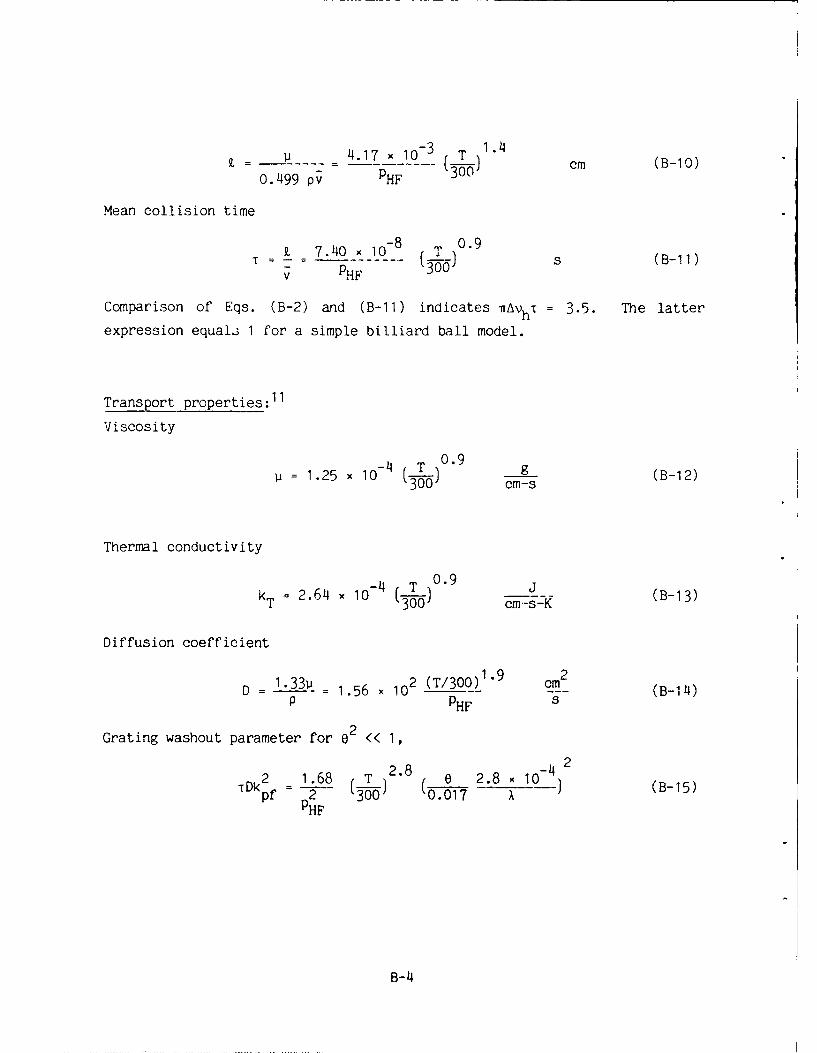
4.17 x 10⁻³ T 1.4-_ 20 (-) cm (B-10)
0.499 pv PHF
Mean collision time
Z 740 1-8 (T0.9
v PHF T0 *9 s (B-11)
Comparison of Eqs. (B-2) and (B-11) indicates AVhT = 3.5. The latter
expression equals 1 for a simple billiard ball model.
Transport properties :11
Viscosity
4 T 0.9 _1.25 x 10- 3 cms (B-12)
Thermal conductivity
k 2.64 104 0.9 j (B-13)
T 00) cm-s-K
Diffusion coefficient
D - 1.33P 1.56 x 10 2 (T/300) 1" 9 cm2. .56. (B-114)P PHF s
Grating washout parameter for 02 << 1,
2 168 T 2.8 2.8 4 2 (B-15)TDkf p 2 3 0.017 A
PHF
B-4

APPENDIX C
DEGENERATE FOUR-WAVE MIXING THEORY
Expressions are derived that define reflection coefficients associated
with four-wave mixing in a homogeneously broadened medium. The
configuration of Fig. 1 is assumed with e2 << I and Ip c << If, b Pump
depletion effects are included.
The electric susceptibility of a homogeneously broadened medium is
x - 2i(I - i6) a(C-a)X = - k f _+ VTfs- C- a
where
6 (V - VO)/[Ah/2] (C-Ib)
= /(0 + 6 ) (C-ic)0
I0(1 + 62) (C-id)
E.Here a0 is the low-power electric-field absorption coefficient evaluated at
0 0line center, Is is saturation intensiti, and I is the line centerS S
saturation intensity [e.g., Eq. (B-5a)]. Other symbols are defined in
Appendix A.
Components of the electric field are expressed in the form
= ie + c.c.] (C-2a)
where
Ei /E s A AizWe-ik'z (C-2b)
C-1

and Es (21s/cc)1 1 2 is the electric field associated with the saturation
intensity Is . The net local intensity I is then
2I E 1 * - z (C-3a)lv i = A.A.e ij (-aTs sT- ijF i Aj e
where
k.. k- . (C-3b)ij 1 j
IkijI =- k ij =27r/Xij (C-3c)
Here i and j each take on the values f, b, p, and c. For i j, Eq. (C-3)
defines interference terms. The wavelengths of the wide and narrow
gratings in Fig. 2 are then, respectively,
pf - k ______
A kf 2 sin (-0/2) (C-14a)pi
pb k (C-4b)
A k = 2cos Ce /2pb
Substitution of Eqs. (C-la) and (C-3a) into the electromagnetic wave
equation yields, 4- 7 for Epc << Ef,b,
dAfdz f - fAf
(C-5a)dz f f
dAb bA (C-5b)
dA bdzp - pA + KA
(C-5c)dz p p (C5c
dA ,d-- a mpA c - KA p (C-5d)
C-2

where
1 A 2 A 2
Ot ~ l-W [I + - (I - f- b- -)~f,b (1i) q 2A 2qf,b
2+2
cc (Ot - ot + OP 3PH PI
2A A)
q3
[q + 2(A 2 + A2 + A2 A2) 1/2
22
The boundary conditions at z = 0 and z =L are
Af (0) =GIVEN A P(0) = GIVEN (C-6a)
A b(L) = GIVEN A (LM) = 0 (C-6b)
Equations (C-5c) and (C-5d) can be combined to yield an expression for the
ratio r(z) 7A c/Ap , namely,
djr t K -* r2 -adz ~pr (C-a
r(L) =0 (C-7b)
where r (0) defines the reflection coefficient. Equation (C-7) is now inte-
grated for the cases of zero and nonzero pump depletion.
C-3

(a) Zero Pump Depletion (aL << 1)
If pump depletion effects are neglected, the coefficients in Eq. (7a)
are independent of z and Eq. (7a) can be integrated to yield
R Ir(O)l2 pR +w cot w(C1,(C
where
W2 _ a 2 (C-8b)
Note that R = Ic(O)/Ip(O) is the intensity reflection coefficient for the
four-wave mixing process. In the limit aL << 1, which is consistent with
the neglect of pump depletion, Eq. (Sa) becomes
= JKLJ 2 [I + O(cIpRL)] (C-9a)
or, equivalently,
(I /s )2 ( - d 2 ) [I + O(pR L)](1 + 2 R t 22 (C-9b)
(a0 L)2 [ + 2 (It/I S ) + (It/I )2d2 ]3
where It = If + Iby and d = if - Ibl/It. The case d = 0, apRL - E L is
considered in Eq. (1).
(b) Nonzero Pump Depletion [EaL = 0(l)]
In the case of nonzero pump depletion, it is con .--nient to write Eqs.
(C-5a) and (C-5b) in the form
d(If/I S ) If
dz = -2cfR I (C-10a)
S
C-Li

d(Ib /1 b (C-b)
dz bR ClS
where
If(O)/I s = GIVEN (C-10c)
Ib(L)/I s = GIVEN (C-10d)
Here afR and abR are the real parts of af and a b respectively. The re-
flectivity r(O) is found by integrating Eqs. (C-7) and (C-l0) in the inter-
val 0 S z L. The latter is a two-point boundary value problem which can
be reduced to a one-point boundary value problem by evaluating If(L)/Is
analytically and integrating from z = L to z = a. When If(O) = Ib(L), the
analytic solution for If(L)/I s is found from (e.g., Ref. 7)
D _[I + ED2 + 2(0 + K)]112
DI [2(1 + K)]1/2
where
K = S - (D2 + 2S + 1)1/2
S = [Ib(L) + If(L)]/Is
D = [Ib(L) - If(L)]/I s
Equation (C-11) applies for gain as well as absorption. Numerical results
for the variation of R with pressure, for a fixed pump intensity, are given
in Fig. 5b. Pump depletion effects increase with increase in the parameterE.
c, which is related to a L. Maxima, from Fig. 5b, are listed in Table 2b.
C-5

APPENDIX D
DIFFUSION EFFECT
Particle diffusion reduces the effectiveness of the gratings induced
by the four-wave mixing process.1 2 The diffusion effect is estimated
herein.
We first consider a homogeneously broadened medium. Let nI and n2
denote particle number density in the lower and upper laser energy
levels. For weak saturation, n2 << n1 , the variation of n2 with time is
given by
3n2 n2 n1 IE12 V2=- - + - + (D-1)at T r
s
where -r is n2 particle lifetime and D is the diffusion coefficient. For
the case of multiple electric fields given by Eq. (C-3a), the steady state
solution of Eq. (D-1) is,
1 A.A.n2 1 . 2 -ik.z (D-2)1 i j 1 + k ij
Each term in Eq. (D-2), for i j, corresponds to an interference
grating. The effect of diffusion is to reduce the amplitude of each2 -1
grating by the factor (1 + TDk. j)_. The reflectivity coefficient R given
in Eq. (C-8a) is the result of two gratings with amplitudes proportional
to AfAp and AbAp, respectively. Let R and RD denote estimates of
reflectivity which exclude and include the effect of diffusion,
respectively. It follows that
RD ( 1/ 2 1/2 2)2 (D-3)
1 + 1 Dk 2 + TDk 2pf pb
where the terms involving kpf and kpb correspond to the wide and narrow
gratings, respectively, in Fig. 2.
D-1

Equations (D-1) and (D-3) apply to an inhomogeneously broadened medium
for cases where 6 < 1 (i.e., for cases where the laser radiation interacts
with particles which have low thermal velocity.) In these cases, T is the
mean particle collision time. It can be shown from expressions in Appendix2 2
B that TDk - (AVd/ vh) . It follows that22
2 AVd2tDkpf - () (2 sin (D-4a)
AVh 22
2 Aos 2 2
rDkPb Avh ( cos (D-'4b)
For an inhomogeneously broadened medium, Avh << V d the narrow grating is
always washed out (i.e., Dkb >> 1). The wide grating will be fully2 py
effective (i.e., -rDk f << 1) when
(OAvd/AVh)2 << 1 (D-5)
In the latter case, the right-hand side of Eq. (D-3) is equal to 1/4.
Equation (D-5) indicates the need for small e when AVd /A h is large.
D-2

APPENDIX E
THERMAL GRATING
In the present experiment, laser energy continuously heats the absorb-
ing medium. After an initial transient, an elevated steady-state tempera-
ture distribution is established along the optical axis. This steady state
temperature has an average value such that heat loss by radial conduction
and by convection equals the energy input. The increase in average temper-
ature, due to laser heating, appears to be of the order of 100 K in the
present experiments. In addition, there are small periodic variations in
temperature associated with each of the standing waves established by the
four-wave mixing process. The corresponding refractive index variations
constitute thermal gratings which are similar to the saturation-induced
gratings discussed in Appendix C. The reflectivity associated with the
thermal gratings is deduced herein.
The net heat addition per unit volume, per unit time, due to laser
radiation, is given byS.. i2tI - oI s A A A.Aie ij-z (E-1)
3i j iJ
The equation for conservation of energy becomes
is * i -iki3. z - T kT2 TI " = PC - + q - 2 (E-2)
where q is the local energy loss per unit volume, per unit time, due to
radial conduction and convection, and kT is the thermal conductivity coef-
ficient. Under steady state conditions, the solution of Eq. (E-2) is, for
i j,
q tI5 A2 - 2a I. (E-3a)a i L
and for i j
E-1

I A.A. -AT.. s i j e j (E-3b)
1j k k2
T ij
The average temperature along the optical axis is the value for which rad-
ial conduction and convection permit Eq. (E-3a) to be satisfied. The quan-
tity AT.. in Eq. (E-3b) is the temperature perturbation associated withl the
grating defined by k..y j
Denote the local index of refraction by n = no + An where An denotes
the perturbation due to AT. The electric susceptibility is then2
X =n 2-1
- (n2 _ 1) + 2n0 A z AT.. (E-4)
Substitution into the wave equation yields
dA * (E-5a)
dz c
dAc -KA (E-5b)
dz pwhe re
2
2ikv An I /2 (1+ (E-5c)k k2 AT (Iflb) b i k b (f
T pf
Note that /k 2 = tan2(0/2) so that this term (i.e., contribution of thepf pb
narrow grating) can be neglected in Eq. (E-5c). Comparison with Eqs. (C-5)
and (C-8) indicates that the reflectivity associated with the thermal grat-
ing is
Rth = tan2 I L (E-6)
Thermal gratings induced by a pulsed laser, with pulse length T and neglig-
ible conduction, have been investigated. 13 The present results agree with
those in Ref. 13 if (k k2 )1 is replaced by t/pc in Eq. (E-5c). ThisT pb p
equivalence can be deduced directly from Eq. (E-2).
E-2

Evaluation of Eq. (E-6) for typical conditions of the present experi-
ment indicates Rt' - 10 . The reflectivity associated with saturation is
of order R - 10 - . Hence, thermal gratings play no role in the present
experiment. However, the increase in mean temperature along the optical
axis does affect fluid property values and thereby affects the performance
of the saturation gratings.
E-3

LABORATORY OPERATIONS
The Aerospace Corporation functions as an "architect-engineer" for national securityprojects, specializing in advanced military space systems. Providing research support, thecorporation's Laboratory Operations conducts experimeatal and theoretical investigations thatfocus on the application of scientific and technical advances to such systems. Vital to the successof these investigations is the technical staff's wide-ranging expertise and its ability to stay currentwith new developments. This expertise is enhanced by a research program aimed at dealing withthe many problems associated with rapidly evolving space systems. Contributing their capabilitiesto the research effort are these individual laboratories:
Aerophysics Laboratory: Launch vehicle and reentry fluid mechanics, heat transferand flight dynamics; chemical and electric propulsion, propellant chemistry, chemicaldynamics, environmental chemistry, trace detection; spacecraft structural mechanics,contamination, thermal and structural control; high temperature thermomechanics, gaskinetics and radiation; cw and pulsed chemical and excimer laser development,including chemical kinetics, spectroscopy, optical resonators, beam control, atmos-pheric propagation, laser effects and countermeasures.
Chemistry and Physics Laboratory: Atmospheric chemical reactions, atmosphericoptics, light scattering, state-specific chemical reactions and radiative signatures ofmissile plumes, sensor out-of-field-of-view rejection, applied laser spectroscopy, laserchemistry, laser optoelectronics, solar cell physics, battery electrochemistry, spacevacuum and radiation effects on materials, lubrication and surface phenomena,thermionic emission, photosensitive materials and detectors, atomic frequency stand-ards, and environmental chemistry.
Electronics Research Laboratory: Microelectronics, solid-state device physics,compound semiconductors, radiation hardening; electro-optics, quantum electronics,solid-state lasers, optical propagation and communications; microwave semiconductordevices, microwave/millimeter wave measurements, diagnostics and radiometry, micro-wave/millimeter wave thermionic devices; atomic time and frequency standards;antennas, rf systems, electromagnetic propagation phenomena, space communicationsystems
Materials Sciences Laboratory: Development of new materials: metals, alloys,ceramics, polymers and their composites, and new forms of carbon; nondestructiveevaluation, component failure analysis and reliability; fracture mechanics and stresscorrosion; analysis and evaluation of materials at cryogenic and elevated temperaturesas well as in space and enemy-induced environments.
Space Sciences Laboratory: Magnetospheric, auroral and cosmic ray physics,wave-particle interactions, magnetospheric plasma waves; atmospheric and ionosphericphysics, density and, composition of the upper atmosphere, remote sensing usingatmospheric radiation; solar physics, infrared astronomy, infrared signature analysis;effects of solar activity, magnetic storms and nuclear explosions on the earth'satmosphere, ionosphere and magnetosphere; effects of electromagnetic and particulateradiations on space systems; space instrumentation.


![The Conjugate Gradient Method...Conjugate Gradient Algorithm [Conjugate Gradient Iteration] The positive definite linear system Ax = b is solved by the conjugate gradient method.](https://static.fdocuments.net/doc/165x107/5e95c1e7f0d0d02fb330942a/the-conjugate-gradient-method-conjugate-gradient-algorithm-conjugate-gradient.jpg)