S-74S, S-74D - New and Used Welding Equipment and Tools ... Service Manual.pdf · S-74S, S-74D...
64
S-74S, S-74D Processes Description MIG (GMAW) Welding Flux Cored (FCAW) Welding (Gas- And Self-Shielded) Wire Feeder TM-1500-10D 2006−07 Eff. w/Serial Number LC029720 File: MIG (GMAW) Visit our website at www.MillerWelds.com
Transcript of S-74S, S-74D - New and Used Welding Equipment and Tools ... Service Manual.pdf · S-74S, S-74D...

S-74S, S-74D
Processes
Description
MIG (GMAW) Welding
Flux Cored (FCAW) Welding
(Gas- And Self-Shielded)
Wire Feeder
TM-1500-10D 2006−07
Eff. w/Serial Number LC029720
File: MIG (GMAW)Visit our website at
www.MillerWelds.com
TABLE OF CONTENTS
SECTION 1 − SAFETY PRECAUTIONS FOR SERVICING 1 . . . . . . . . . . . . . . . . . . . . . . . . . . . . . . . . . . . . . . . . . . 1-1. Symbol Usage 1 . . . . . . . . . . . . . . . . . . . . . . . . . . . . . . . . . . . . . . . . . . . . . . . . . . . . . . . . . . . . . . . . . . . . . . . . 1-2. Servicing Hazards 1 . . . . . . . . . . . . . . . . . . . . . . . . . . . . . . . . . . . . . . . . . . . . . . . . . . . . . . . . . . . . . . . . . . . . 1-3. California Proposition 65 Warnings 2 . . . . . . . . . . . . . . . . . . . . . . . . . . . . . . . . . . . . . . . . . . . . . . . . . . . . . . . 1-4. EMF Information 2 . . . . . . . . . . . . . . . . . . . . . . . . . . . . . . . . . . . . . . . . . . . . . . . . . . . . . . . . . . . . . . . . . . . . . .
SECTION 2 − DEFINITIONS 3 . . . . . . . . . . . . . . . . . . . . . . . . . . . . . . . . . . . . . . . . . . . . . . . . . . . . . . . . . . . . . . . . . . . 2-1. Warning Label Definitions 3 . . . . . . . . . . . . . . . . . . . . . . . . . . . . . . . . . . . . . . . . . . . . . . . . . . . . . . . . . . . . . . 2-2. Rating Label For CE Products 4 . . . . . . . . . . . . . . . . . . . . . . . . . . . . . . . . . . . . . . . . . . . . . . . . . . . . . . . . . . . 2-3. Symbols And Definitions 4 . . . . . . . . . . . . . . . . . . . . . . . . . . . . . . . . . . . . . . . . . . . . . . . . . . . . . . . . . . . . . . .
SECTION 3 − INTRODUCTION 5 . . . . . . . . . . . . . . . . . . . . . . . . . . . . . . . . . . . . . . . . . . . . . . . . . . . . . . . . . . . . . . . . . 3-1. Specifications 5 . . . . . . . . . . . . . . . . . . . . . . . . . . . . . . . . . . . . . . . . . . . . . . . . . . . . . . . . . . . . . . . . . . . . . . . .
SECTION 4 − INSTALLATION 5 . . . . . . . . . . . . . . . . . . . . . . . . . . . . . . . . . . . . . . . . . . . . . . . . . . . . . . . . . . . . . . . . . . 4-1. Site Selection 5 . . . . . . . . . . . . . . . . . . . . . . . . . . . . . . . . . . . . . . . . . . . . . . . . . . . . . . . . . . . . . . . . . . . . . . . . 4-2. Rear Panel Connections And Rotating Drive Assembly 6 . . . . . . . . . . . . . . . . . . . . . . . . . . . . . . . . . . . . . .
4-3. 14-Pin Plug PLG12 Information 7 . . . . . . . . . . . . . . . . . . . . . . . . . . . . . . . . . . . . . . . . . . . . . . . . . . . . . . . . . . 4-4. Gun Recommendation Table 7 . . . . . . . . . . . . . . . . . . . . . . . . . . . . . . . . . . . . . . . . . . . . . . . . . . . . . . . . . . . . 4-5. Wire Type, Size, And Feed Speed Capability Table 7 . . . . . . . . . . . . . . . . . . . . . . . . . . . . . . . . . . . . . . . . . 4-6. Installing And Threading Welding Wire 8 . . . . . . . . . . . . . . . . . . . . . . . . . . . . . . . . . . . . . . . . . . . . . . . . . . . . 4-7. Setting Internal DIP Switches - Prior to S/N LC203769 9 . . . . . . . . . . . . . . . . . . . . . . . . . . . . . . . . . . . . . .
4-8. Setting Internal DIP Switches - Between S/N LC203769 & LC378938 10 . . . . . . . . . . . . . . . . . . . . . . . . . . 4-9. Setting Internal DIP Switches - After S/N LC378938 11 . . . . . . . . . . . . . . . . . . . . . . . . . . . . . . . . . . . . . . . . 4-10. Equipment DIP Switch Settings (For Models With Meters Only) 12 . . . . . . . . . . . . . . . . . . . . . . . . . . . . . . .
SECTION 5 − OPERATION 13 . . . . . . . . . . . . . . . . . . . . . . . . . . . . . . . . . . . . . . . . . . . . . . . . . . . . . . . . . . . . . . . . . . . . 5-1. Power Switch 13 . . . . . . . . . . . . . . . . . . . . . . . . . . . . . . . . . . . . . . . . . . . . . . . . . . . . . . . . . . . . . . . . . . . . . . . .
5-2. Jog/Purge 13 . . . . . . . . . . . . . . . . . . . . . . . . . . . . . . . . . . . . . . . . . . . . . . . . . . . . . . . . . . . . . . . . . . . . . . . . . . . 5-3. Trigger Hold Switch 14 . . . . . . . . . . . . . . . . . . . . . . . . . . . . . . . . . . . . . . . . . . . . . . . . . . . . . . . . . . . . . . . . . . . 5-4. Voltage Control And Digital Meters (For Models With Meters Only) 14 . . . . . . . . . . . . . . . . . . . . . . . . . . . .
SECTION 6 − THEORY OF OPERATION 15 . . . . . . . . . . . . . . . . . . . . . . . . . . . . . . . . . . . . . . . . . . . . . . . . . . . . . . . . SECTION 7 − TROUBLESHOOTING 16 . . . . . . . . . . . . . . . . . . . . . . . . . . . . . . . . . . . . . . . . . . . . . . . . . . . . . . . . . . . .
7-1. Troubleshooting Table 16 . . . . . . . . . . . . . . . . . . . . . . . . . . . . . . . . . . . . . . . . . . . . . . . . . . . . . . . . . . . . . . . . . 7-2. Troubleshooting Circuit Diagram For S-74S/D Swingarc 18 . . . . . . . . . . . . . . . . . . . . . . . . . . . . . . . . . . . . . 7-3. Location Of Circuit Boards 20 . . . . . . . . . . . . . . . . . . . . . . . . . . . . . . . . . . . . . . . . . . . . . . . . . . . . . . . . . . . . . . 7-4. Motor Board PC1 Testing Information 21 . . . . . . . . . . . . . . . . . . . . . . . . . . . . . . . . . . . . . . . . . . . . . . . . . . . . . 7-5. Motor Board PC1 Test Point Values 22 . . . . . . . . . . . . . . . . . . . . . . . . . . . . . . . . . . . . . . . . . . . . . . . . . . . . . .
7-6. Diagnostic LED’s On Motor Board PC1 24 . . . . . . . . . . . . . . . . . . . . . . . . . . . . . . . . . . . . . . . . . . . . . . . . . . . 7-7. Meter Board PC60 Testing Information 25 . . . . . . . . . . . . . . . . . . . . . . . . . . . . . . . . . . . . . . . . . . . . . . . . . . . . 7-8. Meter Board PC60 Test Point Values 25 . . . . . . . . . . . . . . . . . . . . . . . . . . . . . . . . . . . . . . . . . . . . . . . . . . . . . 7-9. Tachometer Board PC51 Testing Information 26 . . . . . . . . . . . . . . . . . . . . . . . . . . . . . . . . . . . . . . . . . . . . . .
SECTION 8 − MAINTENANCE 27 . . . . . . . . . . . . . . . . . . . . . . . . . . . . . . . . . . . . . . . . . . . . . . . . . . . . . . . . . . . . . . . . . 8-1. Routine Maintenance 27 . . . . . . . . . . . . . . . . . . . . . . . . . . . . . . . . . . . . . . . . . . . . . . . . . . . . . . . . . . . . . . . . . . 8-2. Diagnostics 28 . . . . . . . . . . . . . . . . . . . . . . . . . . . . . . . . . . . . . . . . . . . . . . . . . . . . . . . . . . . . . . . . . . . . . . . . . .
SECTION 9 − ELECTRICAL DIAGRAMS 29 . . . . . . . . . . . . . . . . . . . . . . . . . . . . . . . . . . . . . . . . . . . . . . . . . . . . . . . . SECTION 10 − PARTS LIST FOR LC029720 THRU LC676743 44 . . . . . . . . . . . . . . . . . . . . . . . . . . . . . . . . . . . . . . SECTION 11 − PARTS LIST FOR LC676744 AND FOLLOWING 52 . . . . . . . . . . . . . . . . . . . . . . . . . . . . . . . . . . . .
dec_wire_6/05
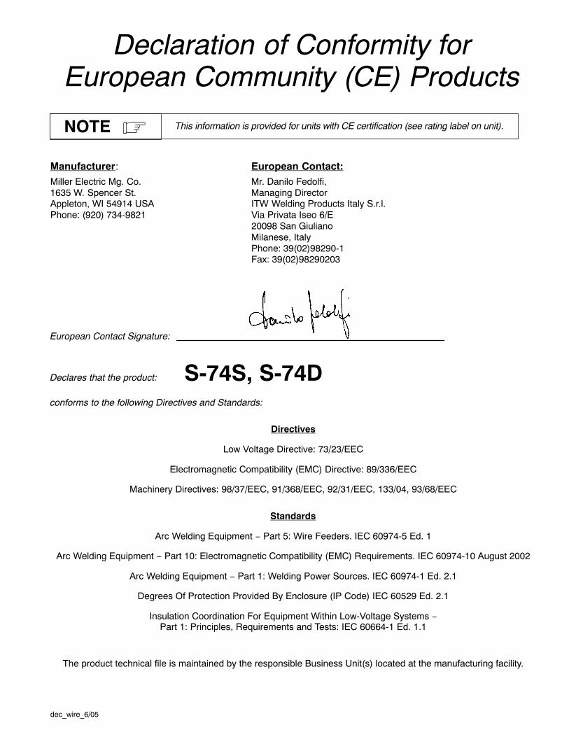
Declaration of Conformity forEuropean Community (CE) Products
This information is provided for units with CE certification (see rating label on unit).NOTE
Manufacturer: European Contact:Miller Electric Mg. Co. Mr. Danilo Fedolfi,1635 W. Spencer St. Managing DirectorAppleton, WI 54914 USA ITW Welding Products Italy S.r.l.Phone: (920) 734-9821 Via Privata Iseo 6/E
20098 San GiulianoMilanese, ItalyPhone: 39(02)98290-1Fax: 39(02)98290203
European Contact Signature:
Declares that the product: S-74S, S-74Dconforms to the following Directives and Standards:
Directives
Low Voltage Directive: 73/23/EEC
Electromagnetic Compatibility (EMC) Directive: 89/336/EEC
Machinery Directives: 98/37/EEC, 91/368/EEC, 92/31/EEC, 133/04, 93/68/EEC
Standards
Arc Welding Equipment − Part 5: Wire Feeders. IEC 60974-5 Ed. 1
Arc Welding Equipment − Part 10: Electromagnetic Compatibility (EMC) Requirements. IEC 60974-10 August 2002
Arc Welding Equipment − Part 1: Welding Power Sources. IEC 60974-1 Ed. 2.1
Degrees Of Protection Provided By Enclosure (IP Code) IEC 60529 Ed. 2.1
Insulation Coordination For Equipment Within Low-Voltage Systems −Part 1: Principles, Requirements and Tests: IEC 60664-1 Ed. 1.1
The product technical file is maintained by the responsible Business Unit(s) located at the manufacturing facility.

TM-1500-10 Page 1S-74S, S-74D
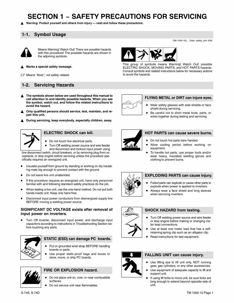
SECTION 1 − SAFETY PRECAUTIONS FOR SERVICING� Warning: Protect yourself and others from injury — read and follow these precautions.
1-1. Symbol UsageOM-1500-10L, - Date, safety_stm 3/06
Means Warning! Watch Out! There are possible hazardswith this procedure! The possible hazards are shown inthe adjoining symbols.
� Marks a special safety message.
� Means “Note”; not safety related.
This group of symbols means Warning! Watch Out! possibleELECTRIC SHOCK, MOVING PARTS, and HOT PARTS hazards.Consult symbols and related instructions below for necessary actionsto avoid the hazards.
1-2. Servicing Hazards
� The symbols shown below are used throughout this manual tocall attention to and identify possible hazards. When you seethe symbol, watch out, and follow the related instructions toavoid the hazard.
� Only qualified persons should service, test, maintain, and re-pair this unit.
� During servicing, keep everybody, especially children, away.
ELECTRIC SHOCK can kill.
� Do not touch live electrical parts.� Turn Off welding power source and wire feeder
and disconnect and lockout input power usingline disconnect switch, circuit breakers, or by removing plug from re-ceptacle, or stop engine before servicing unless the procedure spe-cifically requires an energized unit.
� Insulate yourself from ground by standing or working on dry insulat-ing mats big enough to prevent contact with the ground.
� Do not leave live unit unattended.
� If this procedure requires an energized unit, have only personnelfamiliar with and following standard safety practices do the job.
� When testing a live unit, use the one-hand method. Do not put bothhands inside unit. Keep one hand free.
� Disconnect input power conductors from deenergized supply lineBEFORE moving a welding power source.
SIGNIFICANT DC VOLTAGE exists after removal ofinput power on inverters.
� Turn Off inverter, disconnect input power, and discharge inputcapacitors according to instructions in Troubleshooting Section be-fore touching any parts.
STATIC (ESD) can damage PC boards.
� Put on grounded wrist strap BEFORE handlingboards or parts.
� Use proper static-proof bags and boxes tostore, move, or ship PC boards.
FIRE OR EXPLOSION hazard.
� Do not place unit on, over, or near combustiblesurfaces.
� Do not service unit near flammables.
FLYING METAL or DIRT can injure eyes.
� Wear safety glasses with side shields or faceshield during servicing.
� Be careful not to short metal tools, parts, orwires together during testing and servicing.
HOT PARTS can cause severe burns.
� Do not touch hot parts bare handed.� Allow cooling period before working on
equipment.� To handle hot parts, use proper tools and/or
wear heavy, insulated welding gloves andclothing to prevent burns.
EXPLODING PARTS can cause injury.
� Failed parts can explode or cause other parts toexplode when power is applied to inverters.
� Always wear a face shield and long sleeveswhen servicing inverters.
SHOCK HAZARD from testing.
� Turn Off welding power source and wire feederor stop engine before making or changing me-ter lead connections.
� Use at least one meter lead that has a self-retaining spring clip such as an alligator clip.
� Read instructions for test equipment.
FALLING UNIT can cause injury.
� Use lifting eye to lift unit only, NOT runninggear, gas cylinders, or any other accessories.
� Use equipment of adequate capacity to lift andsupport unit.
� If using lift forks to move unit, be sure forks arelong enough to extend beyond opposite side ofunit.
TM-1500-10 Page 2 S-74S, S-74D
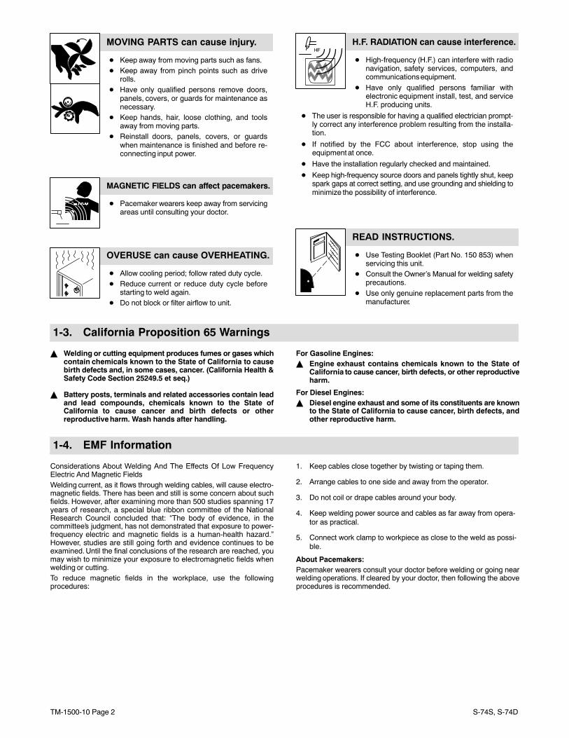
MOVING PARTS can cause injury.
� Keep away from moving parts such as fans.� Keep away from pinch points such as drive
rolls.� Have only qualified persons remove doors,
panels, covers, or guards for maintenance asnecessary.
� Keep hands, hair, loose clothing, and toolsaway from moving parts.
� Reinstall doors, panels, covers, or guardswhen maintenance is finished and before re-connecting input power.
MAGNETIC FIELDS can affect pacemakers.
� Pacemaker wearers keep away from servicingareas until consulting your doctor.
OVERUSE can cause OVERHEATING.
� Allow cooling period; follow rated duty cycle.� Reduce current or reduce duty cycle before
starting to weld again.� Do not block or filter airflow to unit.
H.F. RADIATION can cause interference.
� High-frequency (H.F.) can interfere with radionavigation, safety services, computers, andcommunications equipment.
� Have only qualified persons familiar withelectronic equipment install, test, and serviceH.F. producing units.
� The user is responsible for having a qualified electrician prompt-ly correct any interference problem resulting from the installa-tion.
� If notified by the FCC about interference, stop using theequipment at once.
� Have the installation regularly checked and maintained.
� Keep high-frequency source doors and panels tightly shut, keepspark gaps at correct setting, and use grounding and shielding tominimize the possibility of interference.
READ INSTRUCTIONS.
� Use Testing Booklet (Part No. 150 853) whenservicing this unit.
� Consult the Owner’s Manual for welding safetyprecautions.
� Use only genuine replacement parts from themanufacturer.
1-3. California Proposition 65 Warnings
� Welding or cutting equipment produces fumes or gases whichcontain chemicals known to the State of California to causebirth defects and, in some cases, cancer. (California Health &Safety Code Section 25249.5 et seq.)
� Battery posts, terminals and related accessories contain leadand lead compounds, chemicals known to the State ofCalifornia to cause cancer and birth defects or otherreproductive harm. Wash hands after handling.
For Gasoline Engines:� Engine exhaust contains chemicals known to the State of
California to cause cancer, birth defects, or other reproductiveharm.
For Diesel Engines:� Diesel engine exhaust and some of its constituents are known
to the State of California to cause cancer, birth defects, andother reproductive harm.
1-4. EMF Information
Considerations About Welding And The Effects Of Low FrequencyElectric And Magnetic FieldsWelding current, as it flows through welding cables, will cause electro-magnetic fields. There has been and still is some concern about suchfields. However, after examining more than 500 studies spanning 17years of research, a special blue ribbon committee of the NationalResearch Council concluded that: “The body of evidence, in thecommittee’s judgment, has not demonstrated that exposure to power-frequency electric and magnetic fields is a human-health hazard.”However, studies are still going forth and evidence continues to beexamined. Until the final conclusions of the research are reached, youmay wish to minimize your exposure to electromagnetic fields whenwelding or cutting.To reduce magnetic fields in the workplace, use the followingprocedures:
1. Keep cables close together by twisting or taping them.
2. Arrange cables to one side and away from the operator.
3. Do not coil or drape cables around your body.
4. Keep welding power source and cables as far away from opera-tor as practical.
5. Connect work clamp to workpiece as close to the weld as possi-ble.
About Pacemakers:Pacemaker wearers consult your doctor before welding or going nearwelding operations. If cleared by your doctor, then following the aboveprocedures is recommended.
TM-1500-10 Page 3S-74S, S-74D
SECTION 2 − DEFINITIONS
1 1.1 1.2 1.3
3 3.1 3.2 3.3
4 4.1
+
2 2.1 2.2
+
+
5 6
+
2.3
S-178 936
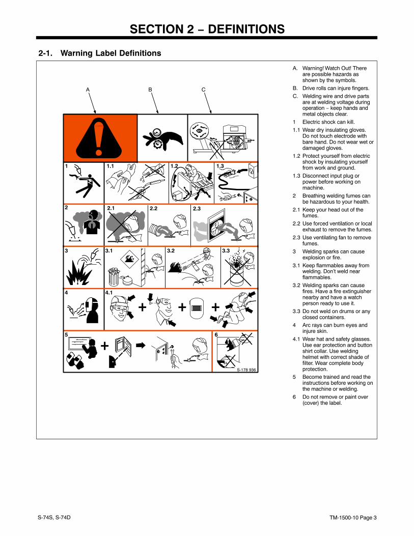
A. Warning! Watch Out! Thereare possible hazards asshown by the symbols.
B. Drive rolls can injure fingers.
C. Welding wire and drive partsare at welding voltage duringoperation − keep hands andmetal objects clear.
1 Electric shock can kill.
1.1 Wear dry insulating gloves.Do not touch electrode withbare hand. Do not wear wet ordamaged gloves.
1.2 Protect yourself from electricshock by insulating yourselffrom work and ground.
1.3 Disconnect input plug orpower before working onmachine.
2 Breathing welding fumes canbe hazardous to your health.
2.1 Keep your head out of thefumes.
2.2 Use forced ventilation or localexhaust to remove the fumes.
2.3 Use ventilating fan to removefumes.
3 Welding sparks can causeexplosion or fire.
3.1 Keep flammables away fromwelding. Don’t weld nearflammables.
3.2 Welding sparks can causefires. Have a fire extinguishernearby and have a watchperson ready to use it.
3.3 Do not weld on drums or anyclosed containers.
4 Arc rays can burn eyes andinjure skin.
4.1 Wear hat and safety glasses.Use ear protection and buttonshirt collar. Use weldinghelmet with correct shade offilter. Wear complete bodyprotection.
5 Become trained and read theinstructions before working onthe machine or welding.
6 Do not remove or paint over(cover) the label.
2-1. Warning Label Definitions
A B C
TM-1500-10 Page 4 S-74S, S-74D
ST-178 794-A
50/60
S/N:
2410.0
Hz50/60IP 21
V100 A750 X 100 %
VU1= A I1=
1
U2=
I2=
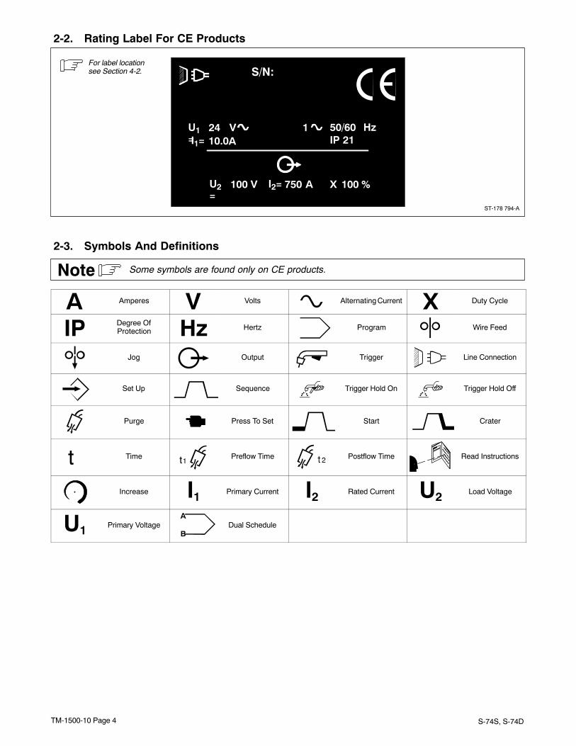
2-2. Rating Label For CE Products
For label locationsee Section 4-2.
2-3. Symbols And Definitions
Some symbols are found only on CE products.Note
A Amperes V Volts Alternating Current X Duty Cycle
IP Degree OfProtection Hz Hertz Program Wire Feed
Jog Output Trigger Line Connection
Set Up Sequence Trigger Hold On Trigger Hold Off
Purge Press To Set Start Crater
Time Preflow Time Postflow Time Read Instructions
Increase I1 Primary Current I2 Rated Current U2 Load Voltage
U1 Primary VoltageA
BDual Schedule
TM-1500-10 Page 5S-74S, S-74D
SECTION 3 − INTRODUCTION
3-1. Specifications
Type of InputPower
Welding PowerSource Type
Wire FeedSpeed Range
WireDiameter
Range
WeldingCircuitRating
IPRating
OverallDimensions Weight
24 Volts acSingle-Phase10 Amperes50/60 Hertz
Constant Voltage (CV)DC With 14-Pin AndContactor Control
Standard: 50 To780 ipm (1.3 To
19.8 mpm)
Optional HighSpeed: 92 To
1435 ipm (2.3 To36.4 mpm)
.023 To 1/8 in(0.6 To 3.2
mm)
Max SpoolWeight: 60 lb
(27 kg)
100 Volts, 750
Amperes,100% Duty
Cycle
IP 21 Length: 27 in(686 mm)
Width: 12-1/2 in(318 mm)
Height: 14 in(356 mm)
45 lb(20.41 kg)
SECTION 4 − INSTALLATION
802 806-A
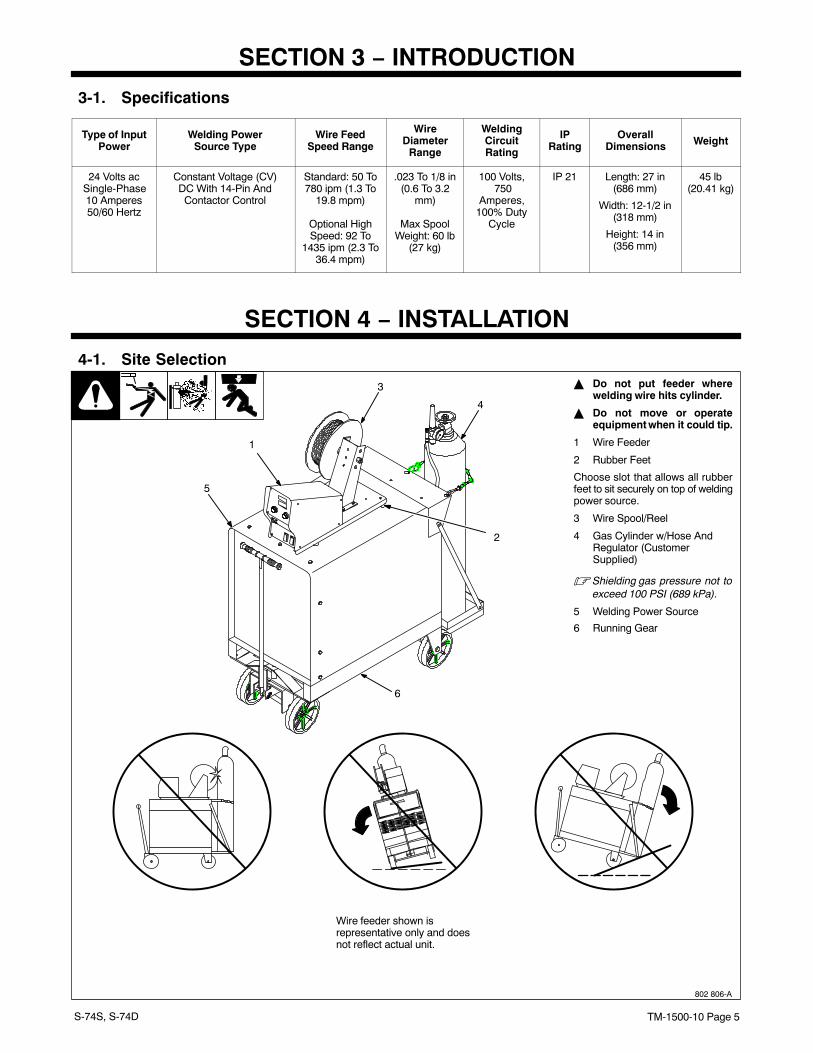
� Do not put feeder wherewelding wire hits cylinder.
� Do not move or operateequipment when it could tip.
1 Wire Feeder
2 Rubber Feet
Choose slot that allows all rubberfeet to sit securely on top of weldingpower source.
3 Wire Spool/Reel
4 Gas Cylinder w/Hose AndRegulator (CustomerSupplied)
� Shielding gas pressure not toexceed 100 PSI (689 kPa).
5 Welding Power Source
6 Running Gear
1
3
5
4
2
4-1. Site Selection
Wire feeder shown isrepresentative only and doesnot reflect actual unit.
6
TM-1500-10 Page 6 S-74S, S-74D
4-2. Rear Panel Connections And Rotating Drive Assembly
802 824-A / 802 825-A
2
3
4
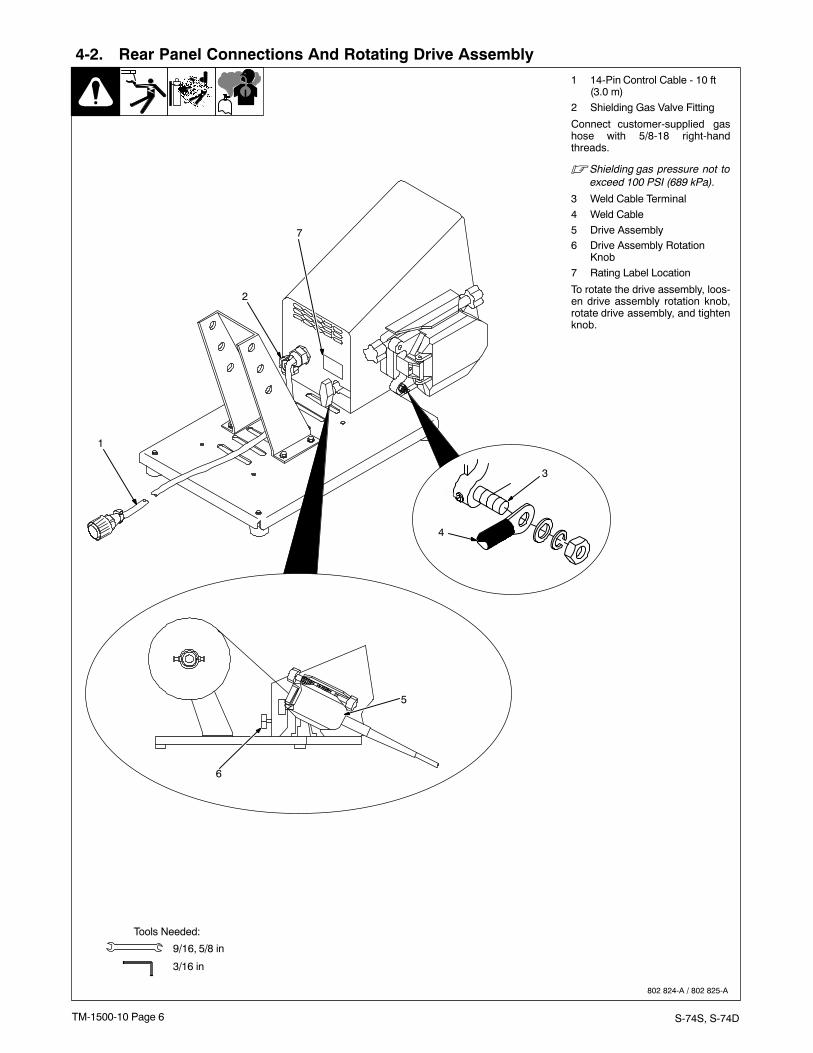
1 14-Pin Control Cable - 10 ft(3.0 m)
2 Shielding Gas Valve Fitting
Connect customer-supplied gashose with 5/8-18 right-handthreads.
� Shielding gas pressure not toexceed 100 PSI (689 kPa).
3 Weld Cable Terminal
4 Weld Cable
5 Drive Assembly6 Drive Assembly Rotation
Knob
7 Rating Label Location
To rotate the drive assembly, loos-en drive assembly rotation knob,rotate drive assembly, and tightenknob.
9/16, 5/8 in
Tools Needed:
3/16 in
5
6
1
7
TM-1500-10 Page 7S-74S, S-74D
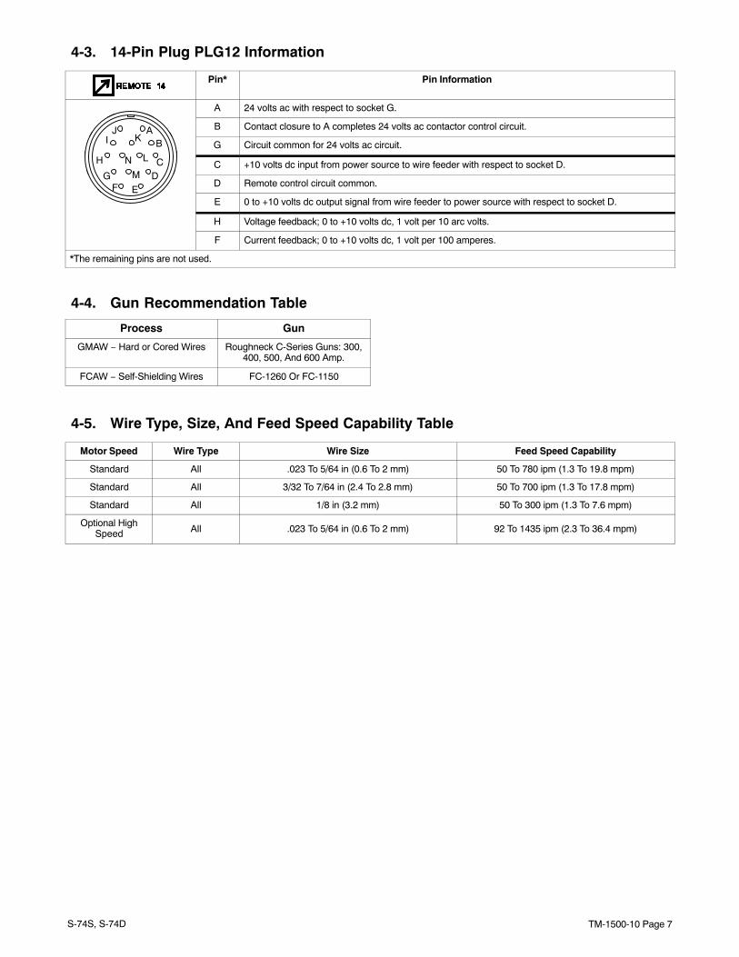
4-3. 14-Pin Plug PLG12 Information
Pin* Pin Information
A 24 volts ac with respect to socket G.
AJK
B Contact closure to A completes 24 volts ac contactor control circuit.AJBKI
LG Circuit common for 24 volts ac circuit.
CLNH
DMGC +10 volts dc input from power source to wire feeder with respect to socket D.
DMGEF D Remote control circuit common.EF
E 0 to +10 volts dc output signal from wire feeder to power source with respect to socket D.
H Voltage feedback; 0 to +10 volts dc, 1 volt per 10 arc volts.
F Current feedback; 0 to +10 volts dc, 1 volt per 100 amperes.
*The remaining pins are not used.
4-4. Gun Recommendation Table
Process Gun
GMAW − Hard or Cored Wires Roughneck C-Series Guns: 300,400, 500, And 600 Amp.
FCAW − Self-Shielding Wires FC-1260 Or FC-1150
4-5. Wire Type, Size, And Feed Speed Capability Table
Motor Speed Wire Type Wire Size Feed Speed Capability
Standard All .023 To 5/64 in (0.6 To 2 mm) 50 To 780 ipm (1.3 To 19.8 mpm)
Standard All 3/32 To 7/64 in (2.4 To 2.8 mm) 50 To 700 ipm (1.3 To 17.8 mpm)
Standard All 1/8 in (3.2 mm) 50 To 300 ipm (1.3 To 7.6 mpm)
Optional HighSpeed All .023 To 5/64 in (0.6 To 2 mm) 92 To 1435 ipm (2.3 To 36.4 mpm)
TM-1500-10 Page 8 S-74S, S-74D
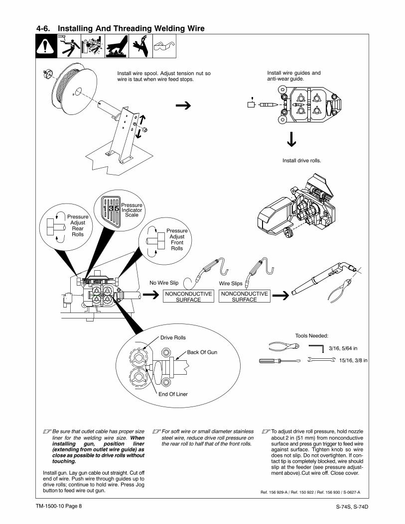
4-6. Installing And Threading Welding Wire
Ref. 156 929-A / Ref. 150 922 / Ref. 156 930 / S-0627-A
Tools Needed:
� Be sure that outlet cable has proper sizeliner for the welding wire size. Wheninstalling gun, position liner(extending from outlet wire guide) asclose as possible to drive rolls withouttouching.
Install gun. Lay gun cable out straight. Cut offend of wire. Push wire through guides up todrive rolls; continue to hold wire. Press Jogbutton to feed wire out gun.
� For soft wire or small diameter stainlesssteel wire, reduce drive roll pressure onthe rear roll to half that of the front rolls.
� To adjust drive roll pressure, hold nozzleabout 2 in (51 mm) from nonconductivesurface and press gun trigger to feed wireagainst surface. Tighten knob so wiredoes not slip. Do not overtighten. If con-tact tip is completely blocked, wire shouldslip at the feeder (see pressure adjust-ment above).Cut wire off. Close cover.
NONCONDUCTIVESURFACE
NONCONDUCTIVESURFACE
No Wire Slip Wire Slips
Install wire spool. Adjust tension nut sowire is taut when wire feed stops.
Install wire guides andanti-wear guide.
Install drive rolls.
3/16, 5/64 in
15/16, 3/8 in
PressureAdjustFrontRolls
PressureIndicator
ScalePressureAdjustRearRolls
Drive Rolls
End Of Liner
Back Of Gun

TM-1500-10 Page 9S-74S, S-74D
4-7. Setting Internal DIP Switches - Prior to S/N LC203769
Position Settings And Results For DIP Switch S1 On PC1 And PC101
On = Current detect over-ride. For welding powersources that don’t providecurrent feedback throughthe 14-pin receptacle. Run-in is inactive.
Off = Current must be detectedfrom power sources that providecurrent feedback through the14-pin receptacle to go from run-into welding condition. Run-in wirespeed is active.
Remove wrapper.
1 DIP Switch S1 On MotorBoard PC1
� Setting Current Detect Override (S1-1)
Current detect override is used todisable run-in when a welding pow-er source is used that doesn’t pro-vide current feedback through the14-pin receptacle.
� Pins F & H are not present in 14pin receptacle on machinesthat don’t provide current feed-back.
Install wrapper when finished.
1
803 063 / Ref. 802 944
� In the DIP switch S1 illustrations,the elevated slider on each switchis shown in white. For example,the switches above are all in theOff position.
� When DIP switch positions are changed, the unit must beturned Off and then On again in order for the new settingsto be active. DIP switches are only read on power up.
Tools Needed:
1/4 in
This illustration showsthe factory setting of S1.
S1-1 And S1-2 S1-1 And S1-2
Current Detect Override (ON) Current Detect Override (OFF)
P1
(Factory Default)
On = Run-In speed isapproximately 1/2 weld wirefeed speed.
Off = Run-In speed is set using po-tentiometer P1 located on Motorboard PC1.
S1-1 And S1-2 S1-1 And S1-2
Automatic Run-In (ON)(Factory Default)
Automatic Run-In (OFF)
TM-1500-10 Page 10 S-74S, S-74D
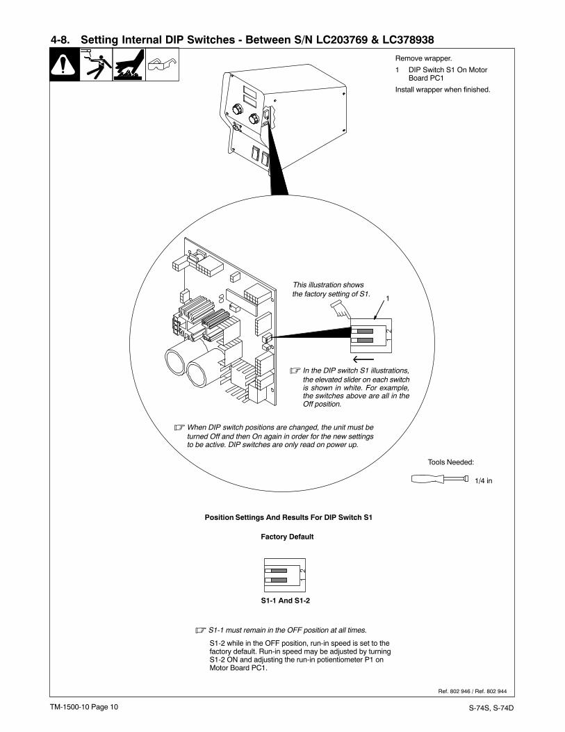
4-8. Setting Internal DIP Switches - Between S/N LC203769 & LC378938
Position Settings And Results For DIP Switch S1
S1-2 while in the OFF position, run-in speed is set to thefactory default. Run-in speed may be adjusted by turningS1-2 ON and adjusting the run-in potientiometer P1 onMotor Board PC1.
Remove wrapper.
1 DIP Switch S1 On MotorBoard PC1
Install wrapper when finished.
Ref. 802 946 / Ref. 802 944
Tools Needed:
1/4 in
S1-1 And S1-2
Factory Default
� S1-1 must remain in the OFF position at all times.
1
� In the DIP switch S1 illustrations,the elevated slider on each switchis shown in white. For example,the switches above are all in theOff position.
� When DIP switch positions are changed, the unit must beturned Off and then On again in order for the new settingsto be active. DIP switches are only read on power up.
This illustration showsthe factory setting of S1.
TM-1500-10 Page 11S-74S, S-74D
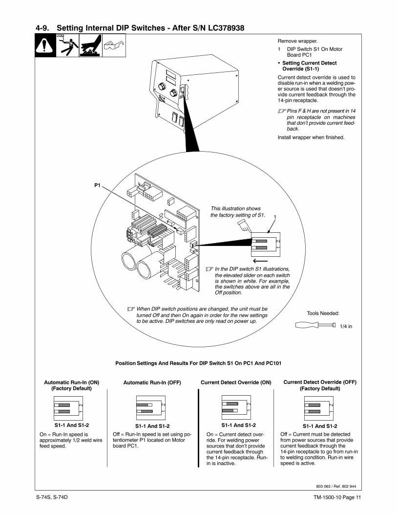
4-9. Setting Internal DIP Switches - After S/N LC378938
Position Settings And Results For DIP Switch S1 On PC1 And PC101
On = Current detect over-ride. For welding powersources that don’t providecurrent feedback throughthe 14-pin receptacle. Run-in is inactive.
Off = Current must be detectedfrom power sources that providecurrent feedback through the14-pin receptacle to go from run-into welding condition. Run-in wirespeed is active.
Remove wrapper.
1 DIP Switch S1 On MotorBoard PC1
� Setting Current Detect Override (S1-1)
Current detect override is used todisable run-in when a welding pow-er source is used that doesn’t pro-vide current feedback through the14-pin receptacle.
� Pins F & H are not present in 14pin receptacle on machinesthat don’t provide current feed-back.
Install wrapper when finished.
1
803 063 / Ref. 802 944
� In the DIP switch S1 illustrations,the elevated slider on each switchis shown in white. For example,the switches above are all in theOff position.
� When DIP switch positions are changed, the unit must beturned Off and then On again in order for the new settingsto be active. DIP switches are only read on power up.
Tools Needed:
1/4 in
This illustration showsthe factory setting of S1.
S1-1 And S1-2 S1-1 And S1-2
Current Detect Override (ON) Current Detect Override (OFF)
P1
(Factory Default)
On = Run-In speed isapproximately 1/2 weld wirefeed speed.
Off = Run-In speed is set using po-tentiometer P1 located on Motorboard PC1.
S1-1 And S1-2 S1-1 And S1-2
Automatic Run-In (ON)(Factory Default)
Automatic Run-In (OFF)
TM-1500-10 Page 12 S-74S, S-74D
Tools Needed:
1/4 in
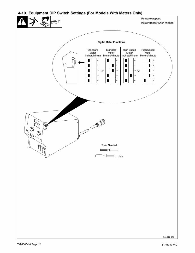
4-10. Equipment DIP Switch Settings (For Models With Meters Only)
12
34
5
Or Or
High SpeedMotor
Meters/Minute
High SpeedMotor
Inches/Minute
StandardMotor
Meters/Minute
StandardMotor
Inches/Minute
Digital Meter Functions
12
34
5
12
34
5
12
34
5
Ref. 802 946
Remove wrapper.
Install wrapper when finished.
TM-1500-10 Page 13S-74S, S-74D
SECTION 5 − OPERATION
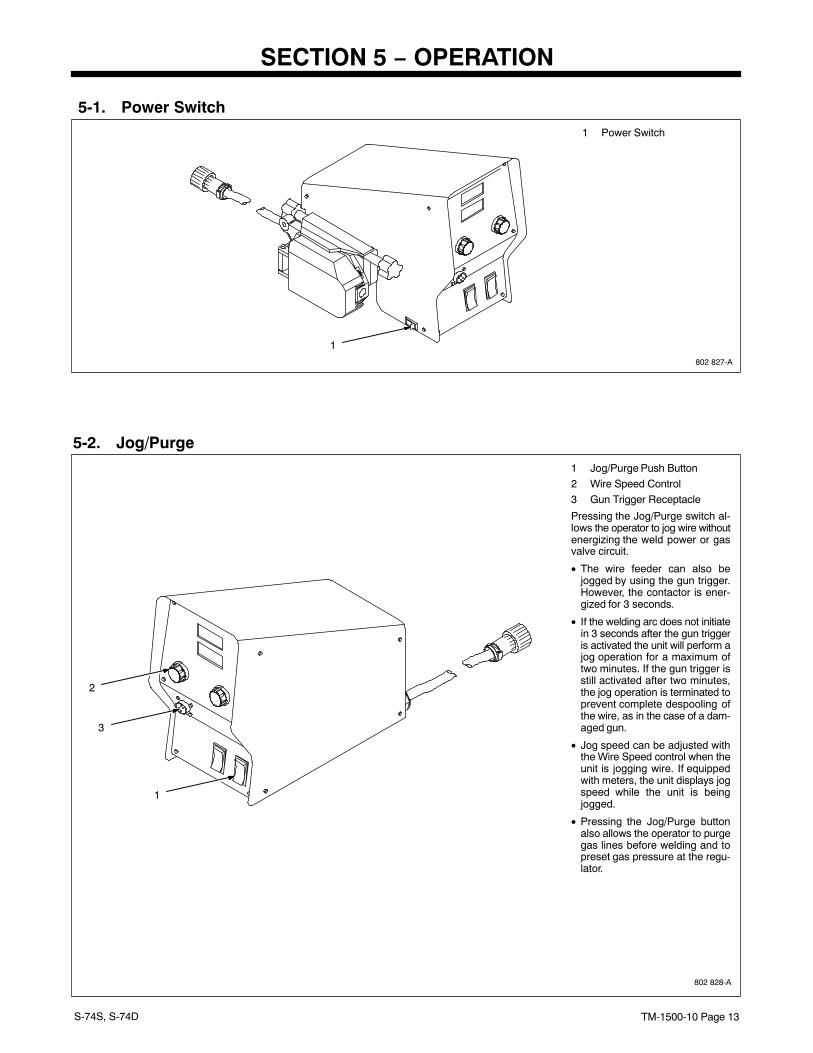
5-1. Power Switch1 Power Switch
1
802 827-A
5-2. Jog/Purge
1
802 828-A
2
1 Jog/Purge Push Button
2 Wire Speed Control
3 Gun Trigger Receptacle
Pressing the Jog/Purge switch al-lows the operator to jog wire withoutenergizing the weld power or gasvalve circuit.
• The wire feeder can also bejogged by using the gun trigger.However, the contactor is ener-gized for 3 seconds.
• If the welding arc does not initiatein 3 seconds after the gun triggeris activated the unit will perform ajog operation for a maximum oftwo minutes. If the gun trigger isstill activated after two minutes,the jog operation is terminated toprevent complete despooling ofthe wire, as in the case of a dam-aged gun.
• Jog speed can be adjusted withthe Wire Speed control when theunit is jogging wire. If equippedwith meters, the unit displays jogspeed while the unit is beingjogged.
• Pressing the Jog/Purge buttonalso allows the operator to purgegas lines before welding and topreset gas pressure at the regu-lator.
3
TM-1500-10 Page 14 S-74S, S-74D
5-3. Trigger Hold Switch
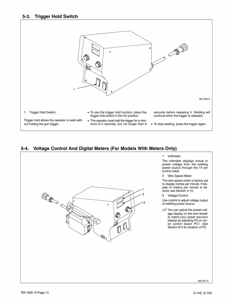
1 Trigger Hold Switch
Trigger hold allows the operator to weld with-out holding the gun trigger.
• To use the trigger hold function, place thetrigger hold switch in the On position.
• The operator must hold the trigger for a mini-mum of 2 seconds, but not longer than 6
seconds before releasing it. Welding willcontinue when the trigger is released.
• To stop welding, press the trigger again.
1
802 828-A
5-4. Voltage Control And Digital Meters (For Models With Meters Only)
3
802 827-A
1
2
1 Voltmeter
The voltmeter displays actual orpreset voltage from the weldingpower source through the 14−pincontrol cable.
2 Wire Speed Meter
The wire speed meter is factory setto display inches per minute. If dis-play of meters per minute is de-sired, see Section 4-10.
3 Voltage Control
Use control to adjust voltage outputof welding power source.
� You can adjust the preset volt-age display on the wire feederto match your power source’sdisplay by adjusting P2 on mo-tor control board PC1. SeeSection 8-2 for location of P2.
TM-1500-10 Page 15S-74S, S-74D
SECTION 6 − THEORY OF OPERATION
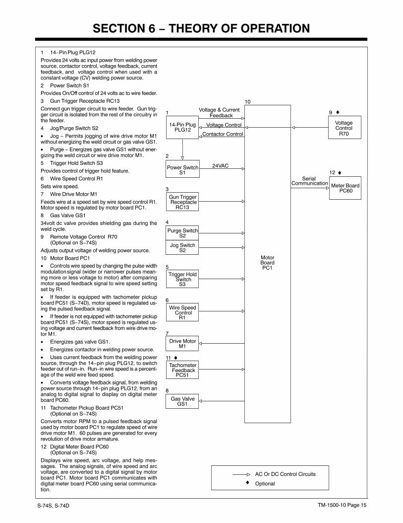
1 14−Pin Plug PLG12
Provides 24 volts ac input power from welding powersource, contactor control, voltage feedback, currentfeedback, and voltage control when used with aconstant voltage (CV) welding power source.
2 Power Switch S1Provides On/Off control of 24 volts ac to wire feeder.
3 Gun Trigger Receptacle RC13
Connect gun trigger circuit to wire feeder. Gun trig-ger circuit is isolated from the rest of the circuitry inthe feeder.
4 Jog/Purge Switch S2
• Jog − Permits jogging of wire drive motor M1without energizing the weld circuit or gas valve GS1.• Purge − Energizes gas valve GS1 without ener-gizing the weld circuit or wire drive motor M1.
5 Trigger Hold Switch S3
Provides control of trigger hold feature.
6 Wire Speed Control R1
Sets wire speed.
7 Wire Drive Motor M1
Feeds wire at a speed set by wire speed control R1.Motor speed is regulated by motor board PC1.
8 Gas Valve GS1
34volt dc valve provides shielding gas during theweld cycle.
9 Remote Voltage Control R70 (Optional on S−74S)
Adjusts output voltage of welding power source.
10 Motor Board PC1• Controls wire speed by changing the pulse widthmodulation signal (wider or narrower pulses mean-ing more or less voltage to motor) after comparingmotor speed feedback signal to wire speed settingset by R1.
• If feeder is equipped with tachometer pickupboard PC51 (S−74D), motor speed is regulated us-ing the pulsed feedback signal.• If feeder is not equipped with tachometer pickupboard PC51 (S−74S), motor speed is regulated us-ing voltage and current feedback from wire drive mo-tor M1.
• Energizes gas valve GS1.
• Energizes contactor in welding power source.
• Uses current feedback from the welding powersource, through the 14−pin plug PLG12, to switchfeeder out of run−in. Run−in wire speed is a percent-age of the weld wire feed speed.
• Converts voltage feedback signal, from weldingpower source through 14−pin plug PLG12, from ananalog to digital signal to display on digital meterboard PC60.
11 Tachometer Pickup Board PC51 (Optional on S−74S)
Converts motor RPM to a pulsed feedback signalused by motor board PC1 to regulate speed of wiredrive motor M1. 60 pulses are generated for everyrevolution of drive motor armature.
12 Digital Meter Board PC60 (Optional on S−74S)
Displays wire speed, arc voltage, and help mes-sages. The analog signals, of wire speed and arcvoltage, are converted to a digital signal by motorboard PC1. Motor board PC1 communicates withdigital meter board PC60 using serial communica-tion.
MotorBoardPC1
10
5
14-Pin PlugPLG12
1
3
♦
♦Voltage
R70
9
SerialCommunication
Control
Meter BoardPC60
12
Voltage Control
Contactor Control
Voltage & CurrentFeedback
Power SwitchS1
24VAC
2
Gun TriggerReceptacle
RC13
Purge SwitchS2
Jog SwitchS2
4
Trigger HoldSwitch
S3
Wire SpeedControl
R1
6
Drive MotorM1
TachometerFeedback
PC51
7
11
Gas ValveGS1
AC Or DC Control Circuits
♦ Optional
8
♦
TM-1500-10 Page 16 S-74S, S-74D
SECTION 7 − TROUBLESHOOTING
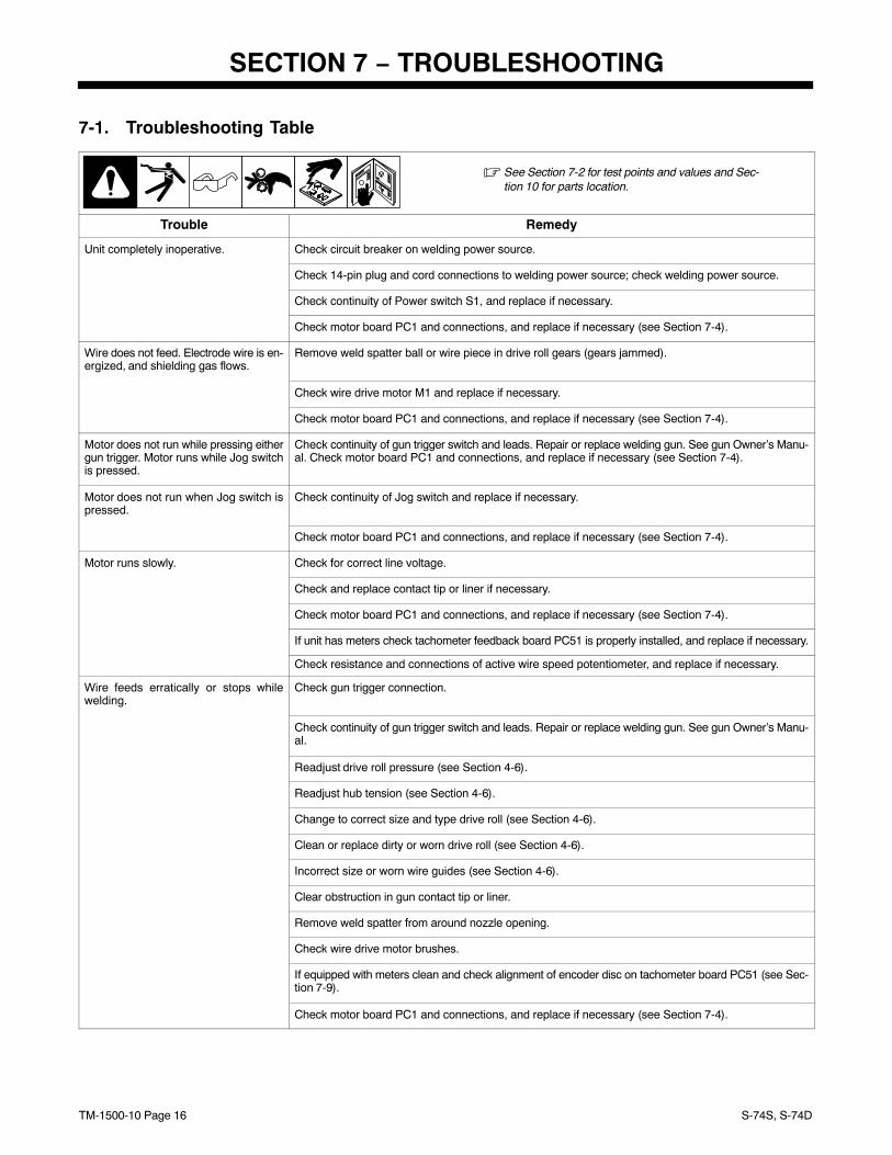
7-1. Troubleshooting Table
� See Section 7-2 for test points and values and Sec-tion 10 for parts location.
Trouble Remedy
Unit completely inoperative. Check circuit breaker on welding power source.
Check 14-pin plug and cord connections to welding power source; check welding power source.
Check continuity of Power switch S1, and replace if necessary.
Check motor board PC1 and connections, and replace if necessary (see Section 7-4).
Wire does not feed. Electrode wire is en-ergized, and shielding gas flows.
Remove weld spatter ball or wire piece in drive roll gears (gears jammed).
Check wire drive motor M1 and replace if necessary.
Check motor board PC1 and connections, and replace if necessary (see Section 7-4).
Motor does not run while pressing eithergun trigger. Motor runs while Jog switchis pressed.
Check continuity of gun trigger switch and leads. Repair or replace welding gun. See gun Owner’s Manu-al. Check motor board PC1 and connections, and replace if necessary (see Section 7-4).
Motor does not run when Jog switch ispressed.
Check continuity of Jog switch and replace if necessary.
Check motor board PC1 and connections, and replace if necessary (see Section 7-4).
Motor runs slowly. Check for correct line voltage.
Check and replace contact tip or liner if necessary.
Check motor board PC1 and connections, and replace if necessary (see Section 7-4).
If unit has meters check tachometer feedback board PC51 is properly installed, and replace if necessary.
Check resistance and connections of active wire speed potentiometer, and replace if necessary.
Wire feeds erratically or stops whilewelding.
Check gun trigger connection.
Check continuity of gun trigger switch and leads. Repair or replace welding gun. See gun Owner’s Manu-al.
Readjust drive roll pressure (see Section 4-6).
Readjust hub tension (see Section 4-6).
Change to correct size and type drive roll (see Section 4-6).
Clean or replace dirty or worn drive roll (see Section 4-6).
Incorrect size or worn wire guides (see Section 4-6).
Clear obstruction in gun contact tip or liner.
Remove weld spatter from around nozzle opening.
Check wire drive motor brushes.
If equipped with meters clean and check alignment of encoder disc on tachometer board PC51 (see Sec-tion 7-9).
Check motor board PC1 and connections, and replace if necessary (see Section 7-4).
TM-1500-10 Page 17S-74S, S-74D
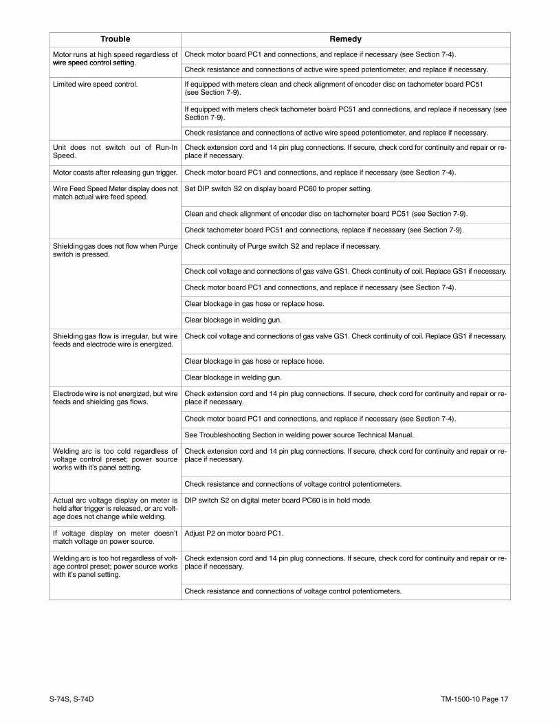
Trouble Remedy
Motor runs at high speed regardless ofwire speed control setting
Check motor board PC1 and connections, and replace if necessary (see Section 7-4).wire speed control setting.
Check resistance and connections of active wire speed potentiometer, and replace if necessary.
Limited wire speed control. If equipped with meters clean and check alignment of encoder disc on tachometer board PC51 (see Section 7-9).
If equipped with meters check tachometer board PC51 and connections, and replace if necessary (seeSection 7-9).
Check resistance and connections of active wire speed potentiometer, and replace if necessary.
Unit does not switch out of Run-InSpeed.
Check extension cord and 14 pin plug connections. If secure, check cord for continuity and repair or re-place if necessary.
Motor coasts after releasing gun trigger. Check motor board PC1 and connections, and replace if necessary (see Section 7-4).
Wire Feed Speed Meter display does notmatch actual wire feed speed.
Set DIP switch S2 on display board PC60 to proper setting.
Clean and check alignment of encoder disc on tachometer board PC51 (see Section 7-9).
Check tachometer board PC51 and connections, replace if necessary (see Section 7-9).
Shielding gas does not flow when Purgeswitch is pressed.
Check continuity of Purge switch S2 and replace if necessary.
Check coil voltage and connections of gas valve GS1. Check continuity of coil. Replace GS1 if necessary.
Check motor board PC1 and connections, and replace if necessary (see Section 7-4).
Clear blockage in gas hose or replace hose.
Clear blockage in welding gun.
Shielding gas flow is irregular, but wirefeeds and electrode wire is energized.
Check coil voltage and connections of gas valve GS1. Check continuity of coil. Replace GS1 if necessary.
Clear blockage in gas hose or replace hose.
Clear blockage in welding gun.
Electrode wire is not energized, but wirefeeds and shielding gas flows.
Check extension cord and 14 pin plug connections. If secure, check cord for continuity and repair or re-place if necessary.
Check motor board PC1 and connections, and replace if necessary (see Section 7-4).
See Troubleshooting Section in welding power source Technical Manual.
Welding arc is too cold regardless ofvoltage control preset; power sourceworks with it’s panel setting.
Check extension cord and 14 pin plug connections. If secure, check cord for continuity and repair or re-place if necessary.
Check resistance and connections of voltage control potentiometers.
Actual arc voltage display on meter isheld after trigger is released, or arc volt-age does not change while welding.
DIP switch S2 on digital meter board PC60 is in hold mode.
If voltage display on meter doesn’tmatch voltage on power source.
Adjust P2 on motor board PC1.
Welding arc is too hot regardless of volt-age control preset; power source workswith it’s panel setting.
Check extension cord and 14 pin plug connections. If secure, check cord for continuity and repair or re-place if necessary.
Check resistance and connections of voltage control potentiometers.
TM-1500-10 Page 18 S-74S, S-74D
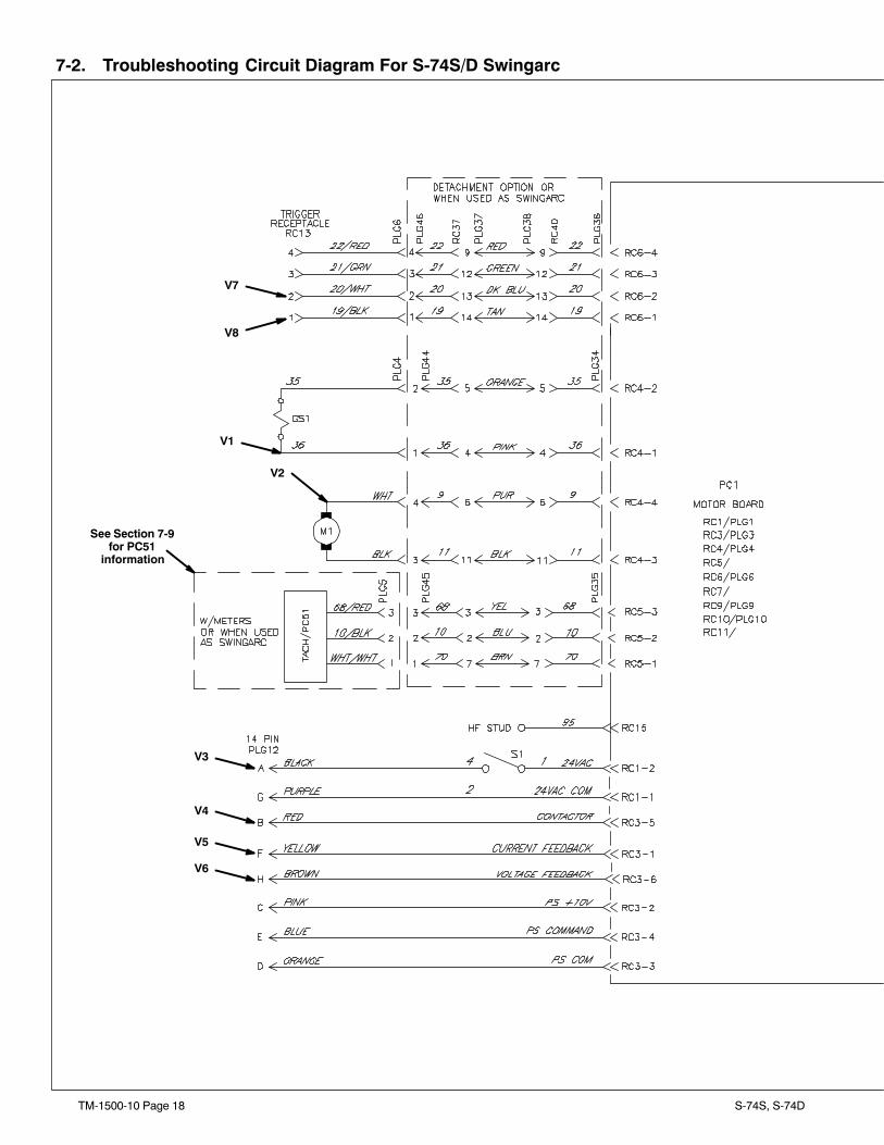
7-2. Troubleshooting Circuit Diagram For S-74S/D Swingarc
V7
See Section 7-9for PC51
information
V8
V1
V2
V3
V4
V5
V6
TM-1500-10 Page 19S-74S, S-74D
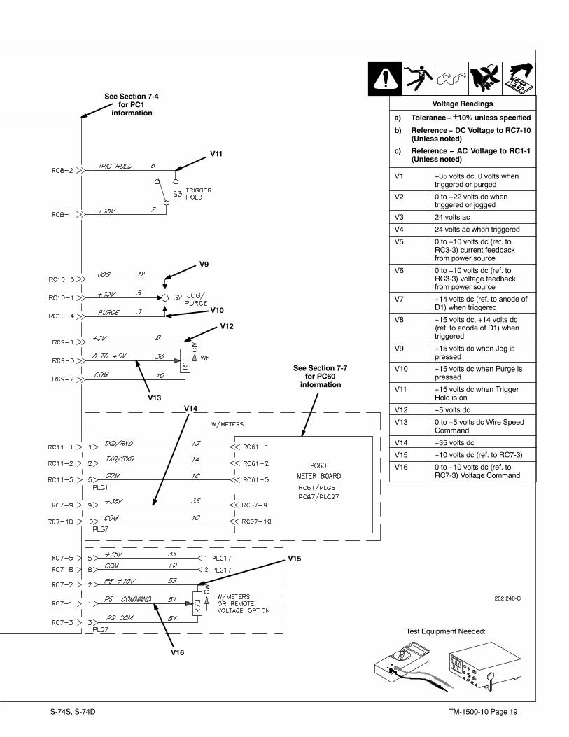
202 246-C
Voltage Readings
a) Tolerance − ±10% unless specified
b) Reference − DC Voltage to RC7-10(Unless noted)
c) Reference − AC Voltage to RC1-1(Unless noted)
V1 +35 volts dc, 0 volts whentriggered or purged
V2 0 to +22 volts dc whentriggered or jogged
V3 24 volts ac
V4 24 volts ac when triggered
V5 0 to +10 volts dc (ref. toRC3-3) current feedbackfrom power source
V6 0 to +10 volts dc (ref. toRC3-3) voltage feedbackfrom power source
V7 +14 volts dc (ref. to anode ofD1) when triggered
V8 +15 volts dc, +14 volts dc(ref. to anode of D1) whentriggered
V9 +15 volts dc when Jog ispressed
V10 +15 volts dc when Purge ispressed
V11 +15 volts dc when TriggerHold is on
V12 +5 volts dc
V13 0 to +5 volts dc Wire SpeedCommand
V14 +35 volts dc
V15 +10 volts dc (ref. to RC7-3)
V16 0 to +10 volts dc (ref. toRC7-3) Voltage Command
Test Equipment Needed:
V9
V11
V10
V12
V13V14
V15
V16
See Section 7-7for PC60
information
See Section 7-4for PC1
information
TM-1500-10 Page 20 S-74S, S-74D
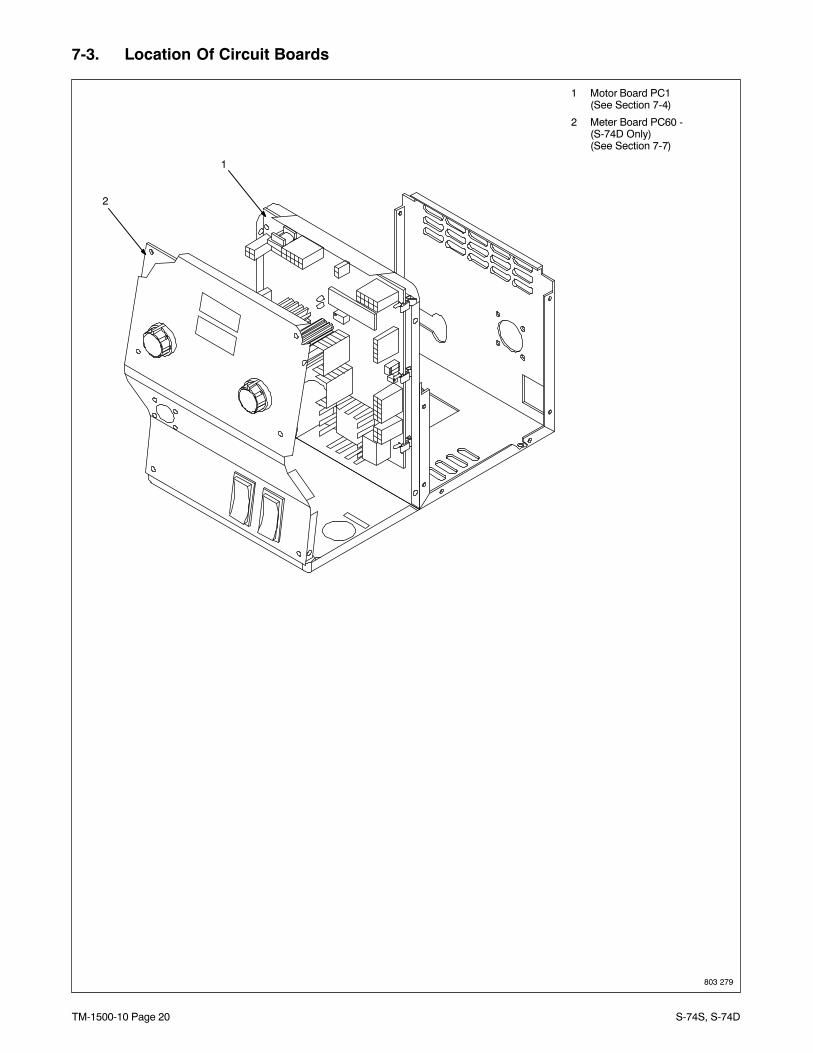
7-3. Location Of Circuit Boards
1 Motor Board PC1 (See Section 7-4)
2 Meter Board PC60 - (S-74D Only)(See Section 7-7)
2
803 279
1
TM-1500-10 Page 21S-74S, S-74D
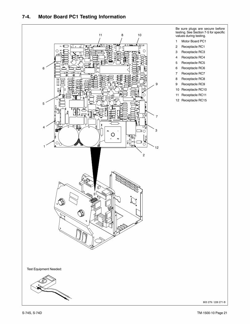
7-4. Motor Board PC1 Testing Information
Test Equipment Needed:
Be sure plugs are secure beforetesting. See Section 7-5 for specificvalues during testing.
1 Motor Board PC1
2 Receptacle RC1
3 Receptacle RC3
4 Receptacle RC4
5 Receptacle RC5
6 Receptacle RC6
7 Receptacle RC7
8 Receptacle RC8
9 Receptacle RC9
10 Receptacle RC10
11 Receptacle RC11
12 Receptacle RC15
803 279 / 226 271-B
6
11 8 10
9
7
4
5
3
12
2
1
TM-1500-10 Page 22 S-74S, S-74D
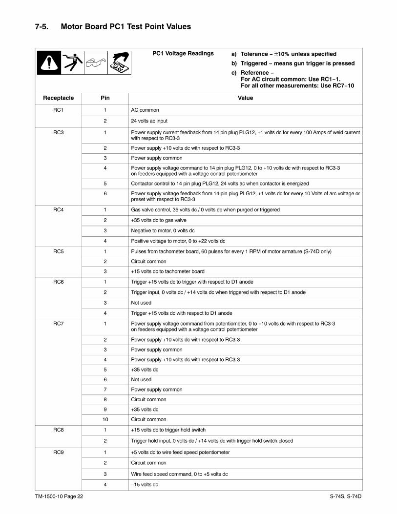
7-5. Motor Board PC1 Test Point Values
a) Tolerance − ±10% unless specified
b) Triggered − means gun trigger is pressed
c) Reference −For AC circuit common: Use RC1−1.For all other measurements: Use RC7−10
PC1 Voltage Readings
Receptacle Pin Value
RC1 1 AC common
2 24 volts ac input
RC3 1 Power supply current feedback from 14 pin plug PLG12, +1 volts dc for every 100 Amps of weld currentwith respect to RC3-3
2 Power supply +10 volts dc with respect to RC3-3
3 Power supply common
4 Power supply voltage command to 14 pin plug PLG12, 0 to +10 volts dc with respect to RC3-3 on feeders equipped with a voltage control potentiometer
5 Contactor control to 14 pin plug PLG12, 24 volts ac when contactor is energized
6 Power supply voltage feedback from 14 pin plug PLG12, +1 volts dc for every 10 Volts of arc voltage orpreset with respect to RC3-3
RC4 1 Gas valve control, 35 volts dc / 0 volts dc when purged or triggered
2 +35 volts dc to gas valve
3 Negative to motor, 0 volts dc
4 Positive voltage to motor, 0 to +22 volts dc
RC5 1 Pulses from tachometer board, 60 pulses for every 1 RPM of motor armature (S-74D only)
2 Circuit common
3 +15 volts dc to tachometer board
RC6 1 Trigger +15 volts dc to trigger with respect to D1 anode
2 Trigger input, 0 volts dc / +14 volts dc when triggered with respect to D1 anode
3 Not used
4 Trigger +15 volts dc with respect to D1 anode
RC7 1 Power supply voltage command from potentiometer, 0 to +10 volts dc with respect to RC3-3on feeders equipped with a voltage control potentiometer
2 Power supply +10 volts dc with respect to RC3-3
3 Power supply common
4 Power supply +10 volts dc with respect to RC3-3
5 +35 volts dc
6 Not used
7 Power supply common
8 Circuit common
9 +35 volts dc
10 Circuit common
RC8 1 +15 volts dc to trigger hold switch
2 Trigger hold input, 0 volts dc / +14 volts dc with trigger hold switch closed
RC9 1 +5 volts dc to wire feed speed potentiometer
2 Circuit common
3 Wire feed speed command, 0 to +5 volts dc
4 −15 volts dc
TM-1500-10 Page 23S-74S, S-74D
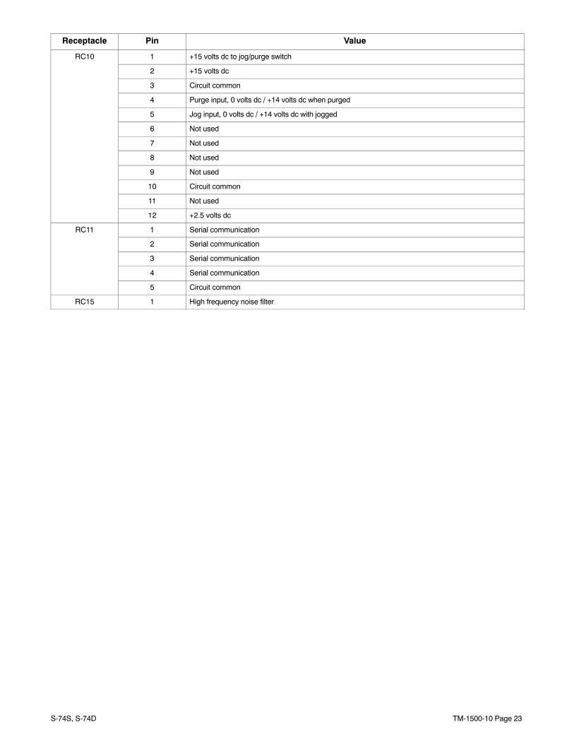
Receptacle Pin Value
RC10 1 +15 volts dc to jog/purge switch
2 +15 volts dc
3 Circuit common
4 Purge input, 0 volts dc / +14 volts dc when purged
5 Jog input, 0 volts dc / +14 volts dc with jogged
6 Not used
7 Not used
8 Not used
9 Not used
10 Circuit common
11 Not used
12 +2.5 volts dc
RC11 1 Serial communication
2 Serial communication
3 Serial communication
4 Serial communication
5 Circuit common
RC15 1 High frequency noise filter
TM-1500-10 Page 24 S-74S, S-74D
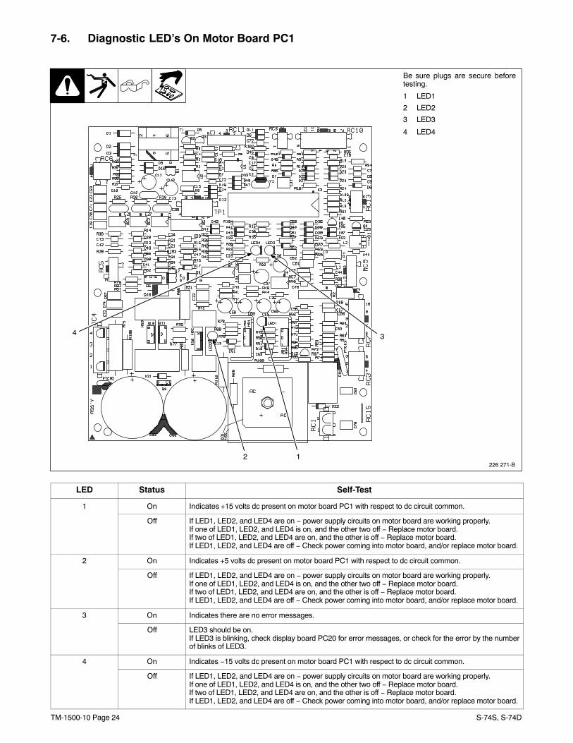
7-6. Diagnostic LED’s On Motor Board PC1
226 271-B
Be sure plugs are secure beforetesting.
1 LED1
2 LED2
3 LED3
4 LED4
12
4 3
LED Status Self-Test
1 On Indicates +15 volts dc present on motor board PC1 with respect to dc circuit common.
Off If LED1, LED2, and LED4 are on − power supply circuits on motor board are working properly.If one of LED1, LED2, and LED4 is on, and the other two off − Replace motor board.If two of LED1, LED2, and LED4 are on, and the other is off − Replace motor board.If LED1, LED2, and LED4 are off − Check power coming into motor board, and/or replace motor board.
2 On Indicates +5 volts dc present on motor board PC1 with respect to dc circuit common.
Off If LED1, LED2, and LED4 are on − power supply circuits on motor board are working properly.If one of LED1, LED2, and LED4 is on, and the other two off − Replace motor board.If two of LED1, LED2, and LED4 are on, and the other is off − Replace motor board.If LED1, LED2, and LED4 are off − Check power coming into motor board, and/or replace motor board.
3 On Indicates there are no error messages.
Off LED3 should be on.If LED3 is blinking, check display board PC20 for error messages, or check for the error by the numberof blinks of LED3.
4 On Indicates −15 volts dc present on motor board PC1 with respect to dc circuit common.
Off If LED1, LED2, and LED4 are on − power supply circuits on motor board are working properly.If one of LED1, LED2, and LED4 is on, and the other two off − Replace motor board.If two of LED1, LED2, and LED4 are on, and the other is off − Replace motor board.If LED1, LED2, and LED4 are off − Check power coming into motor board, and/or replace motor board.
TM-1500-10 Page 25S-74S, S-74D
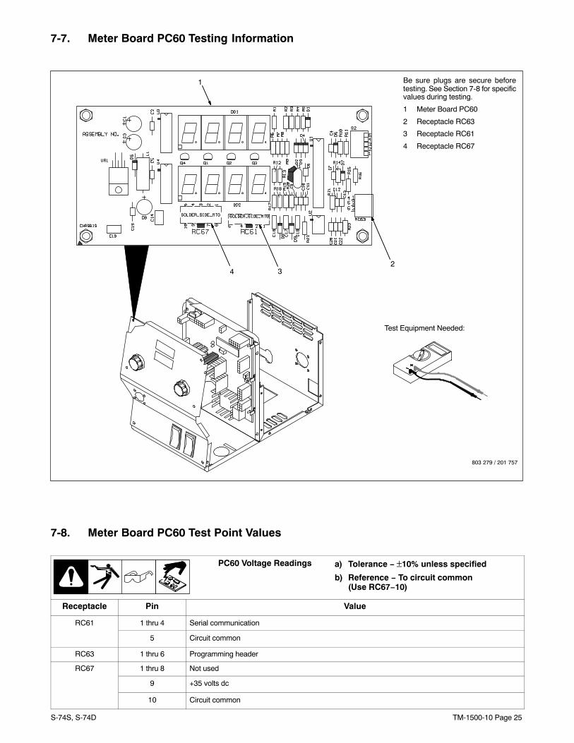
7-7. Meter Board PC60 Testing Information
Test Equipment Needed:
Be sure plugs are secure beforetesting. See Section 7-8 for specificvalues during testing.
1 Meter Board PC60
2 Receptacle RC63
3 Receptacle RC61
4 Receptacle RC67
2
1
803 279 / 201 757
34
7-8. Meter Board PC60 Test Point Values
a) Tolerance − ±10% unless specified
b) Reference − To circuit common (Use RC67−10)
PC60 Voltage Readings
Receptacle Pin Value
RC61 1 thru 4 Serial communication
5 Circuit common
RC63 1 thru 6 Programming header
RC67 1 thru 8 Not used
9 +35 volts dc
10 Circuit common
TM-1500-10 Page 26 S-74S, S-74D
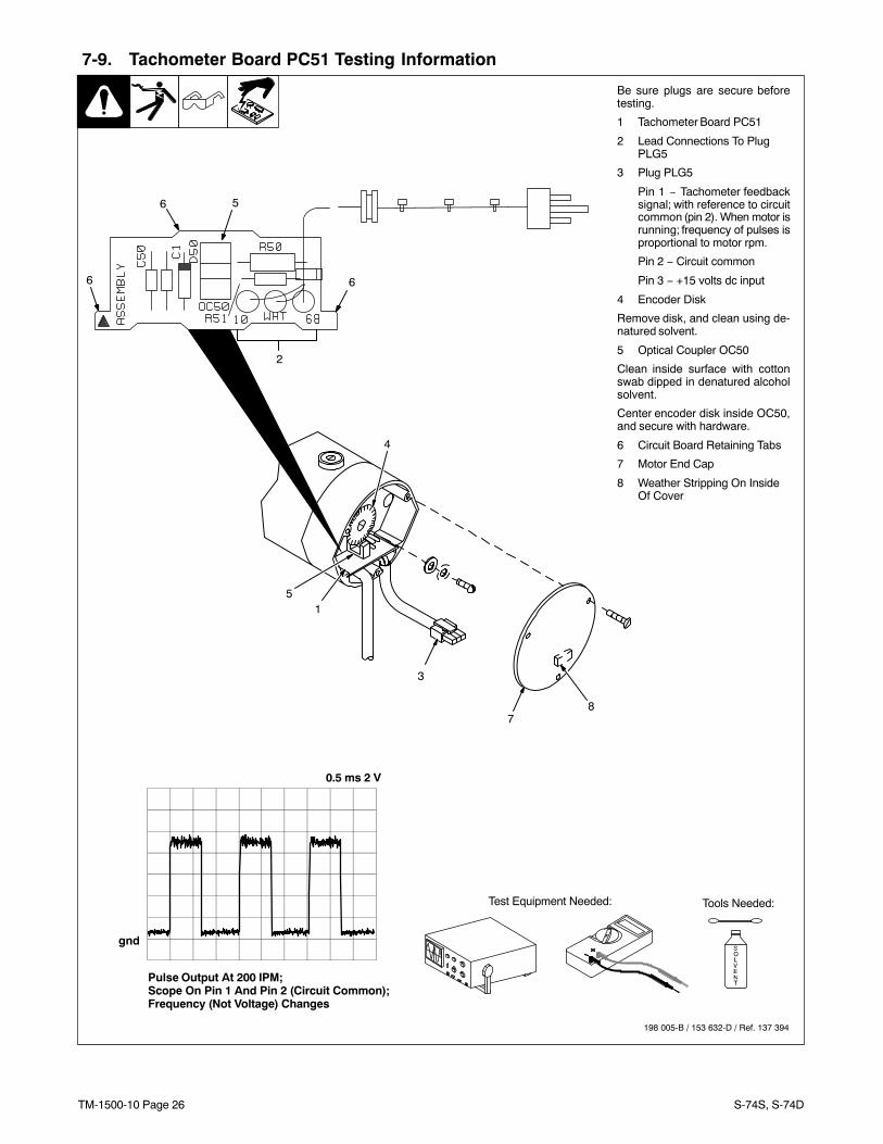
7-9. Tachometer Board PC51 Testing Information
Be sure plugs are secure beforetesting.
1 Tachometer Board PC51
2 Lead Connections To PlugPLG5
3 Plug PLG5
Pin 1 − Tachometer feedbacksignal; with reference to circuitcommon (pin 2). When motor isrunning; frequency of pulses isproportional to motor rpm.
Pin 2 − Circuit common
Pin 3 − +15 volts dc input
4 Encoder Disk
Remove disk, and clean using de-natured solvent.
5 Optical Coupler OC50
Clean inside surface with cottonswab dipped in denatured alcoholsolvent.
Center encoder disk inside OC50,and secure with hardware.
6 Circuit Board Retaining Tabs
7 Motor End Cap
8 Weather Stripping On InsideOf Cover
Test Equipment Needed:
198 005-B / 153 632-D / Ref. 137 394
Pulse Output At 200 IPM;Scope On Pin 1 And Pin 2 (Circuit Common);Frequency (Not Voltage) Changes
0.5 ms 2 V
gnd
5
4
1
87
3
Tools Needed:
2
6 6
6 5
TM-1500-10 Page 27S-74S, S-74D
SECTION 8 − MAINTENANCE
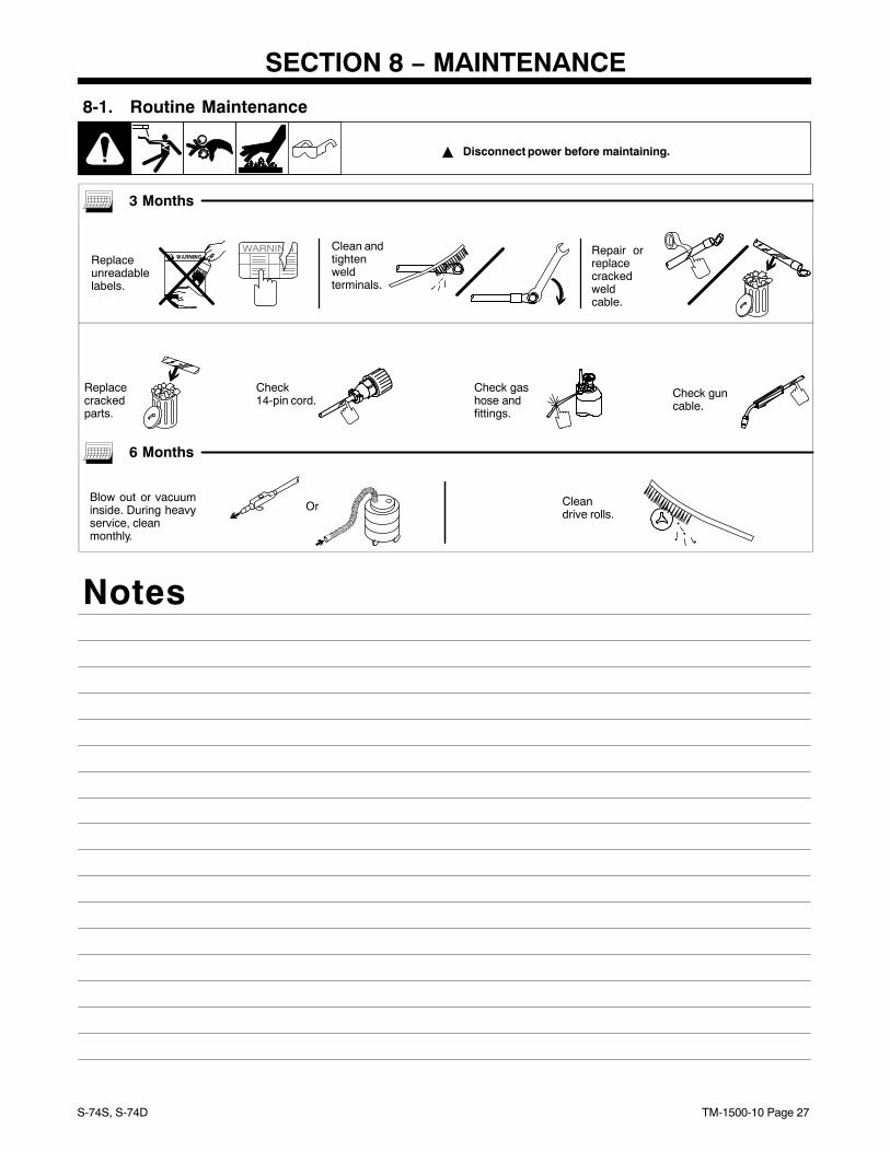
8-1. Routine Maintenance
� Disconnect power before maintaining.
3 Months
Replaceunreadablelabels.
Clean andtightenweldterminals.
Repair orreplacecrackedweldcable.
Check14-pin cord.
Check gashose andfittings.
Check guncable.
Replacecrackedparts.
6 Months
Blow out or vacuuminside. During heavyservice, cleanmonthly.
Or Cleandrive rolls.
Notes
TM-1500-10 Page 28 S-74S, S-74D
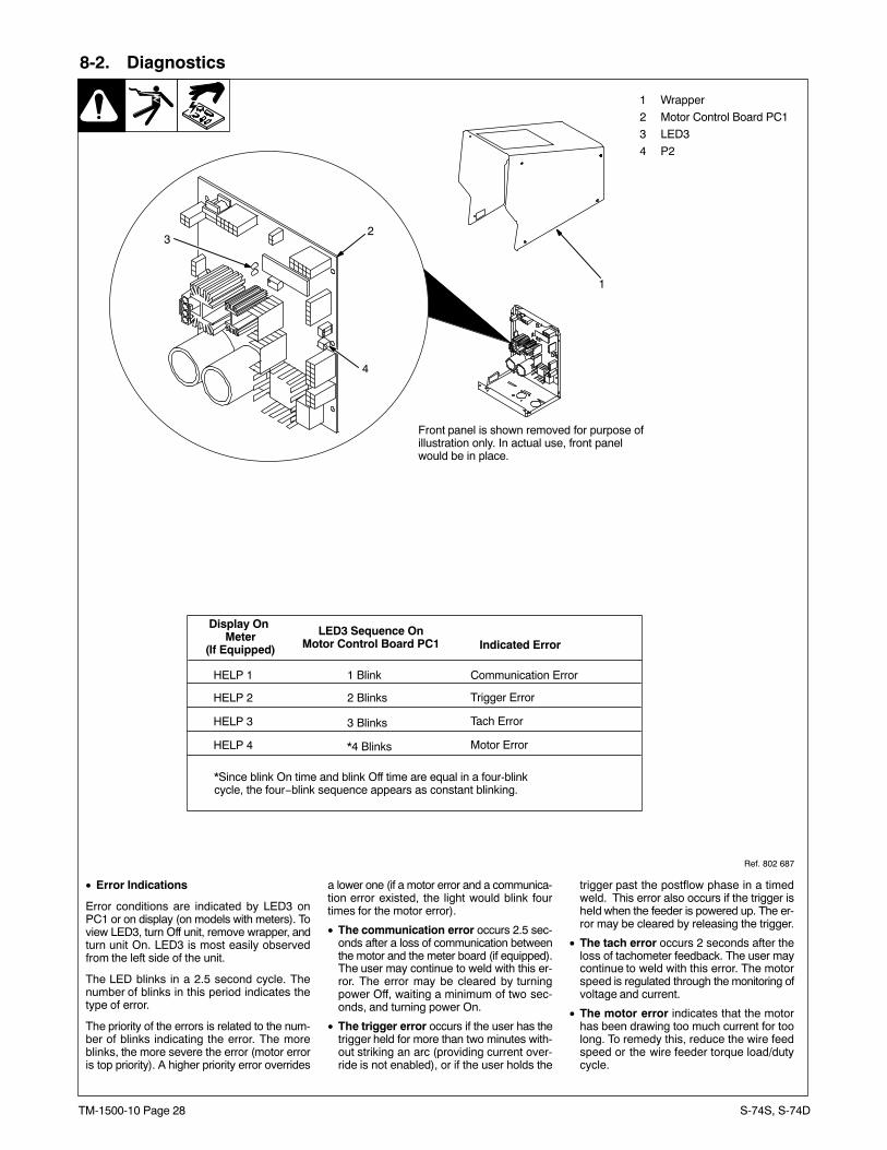
8-2. Diagnostics
• Error Indications
Error conditions are indicated by LED3 onPC1 or on display (on models with meters). Toview LED3, turn Off unit, remove wrapper, andturn unit On. LED3 is most easily observedfrom the left side of the unit.
The LED blinks in a 2.5 second cycle. Thenumber of blinks in this period indicates thetype of error.
The priority of the errors is related to the num-ber of blinks indicating the error. The moreblinks, the more severe the error (motor erroris top priority). A higher priority error overrides
a lower one (if a motor error and a communica-tion error existed, the light would blink fourtimes for the motor error).
• The communication error occurs 2.5 sec-onds after a loss of communication betweenthe motor and the meter board (if equipped).The user may continue to weld with this er-ror. The error may be cleared by turningpower Off, waiting a minimum of two sec-onds, and turning power On.
• The trigger error occurs if the user has thetrigger held for more than two minutes with-out striking an arc (providing current over-ride is not enabled), or if the user holds the
trigger past the postflow phase in a timedweld. This error also occurs if the trigger isheld when the feeder is powered up. The er-ror may be cleared by releasing the trigger.
• The tach error occurs 2 seconds after theloss of tachometer feedback. The user maycontinue to weld with this error. The motorspeed is regulated through the monitoring ofvoltage and current.
• The motor error indicates that the motorhas been drawing too much current for toolong. To remedy this, reduce the wire feedspeed or the wire feeder torque load/dutycycle.
2
Ref. 802 687
1
Front panel is shown removed for purpose of illustration only. In actual use, front panelwould be in place.
Display On Meter
(If Equipped) Indicated ErrorLED3 Sequence On
Motor Control Board PC1
HELP 1
HELP 2
HELP 3
HELP 4
1 Blink
2 Blinks
3 Blinks
*4 Blinks
Communication Error
Trigger Error
Tach Error
Motor Error
*Since blink On time and blink Off time are equal in a four-blinkcycle, the four−blink sequence appears as constant blinking.
3
1 Wrapper
2 Motor Control Board PC1
3 LED3
4 P2
4
TM-1500-10 Page 29S-74S, S-74D
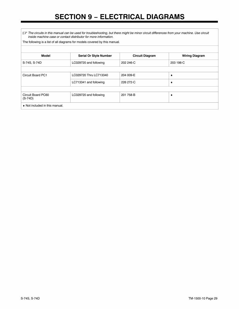
SECTION 9 − ELECTRICAL DIAGRAMS
� The circuits in this manual can be used for troubleshooting, but there might be minor circuit differences from your machine. Use circuitinside machine case or contact distributor for more information.
The following is a list of all diagrams for models covered by this manual.
Model Serial Or Style Number Circuit Diagram Wiring Diagram
S-74S, S-74D LC029720 and following 202 246-C 203 198-C
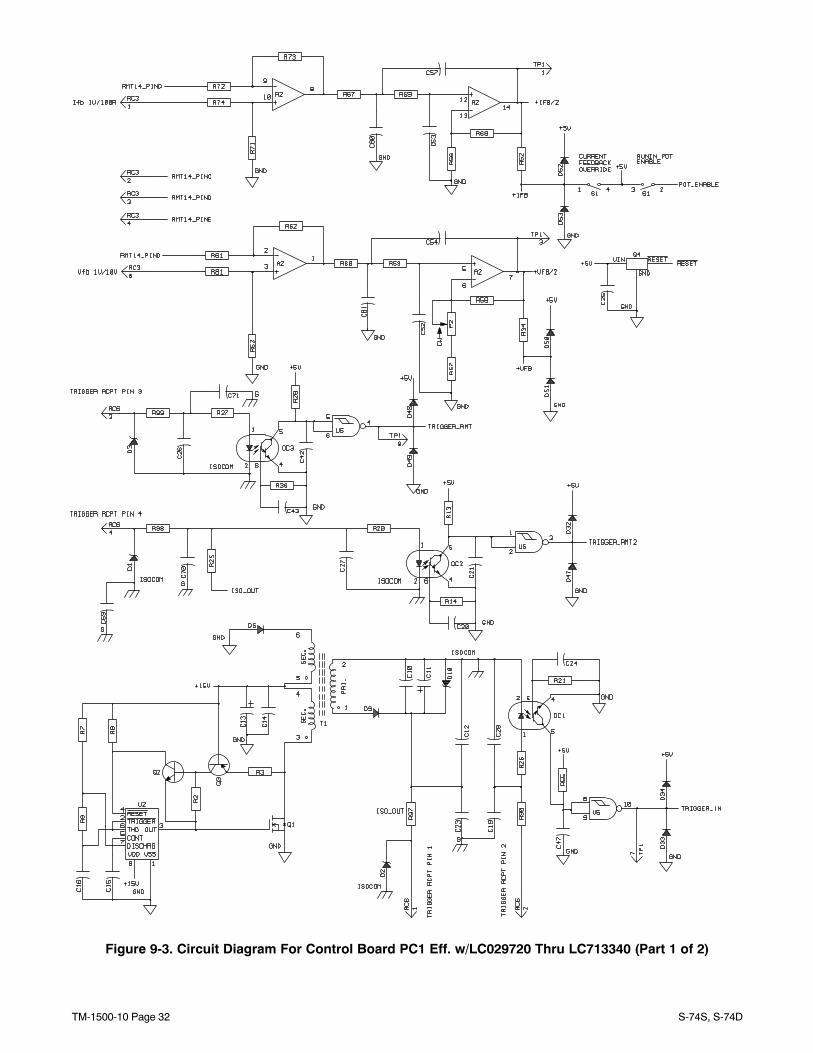
Circuit Board PC1 LC029720 Thru LC713340 204 009-E ♦
LC713341 and following 226 272-C ♦
Circuit Board PC60(S-74D)
LC029720 and following 201 758-B ♦
♦ Not included in this manual.
TM-1500-10 Page 30 S-74S, S-74D
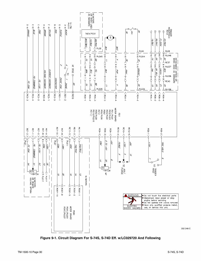
Figure 9-1. Circuit Diagram For S-74S, S-74D Eff. w/LC029720 And Following
202 246-C
TM-1500-10 Page 31S-74S, S-74D
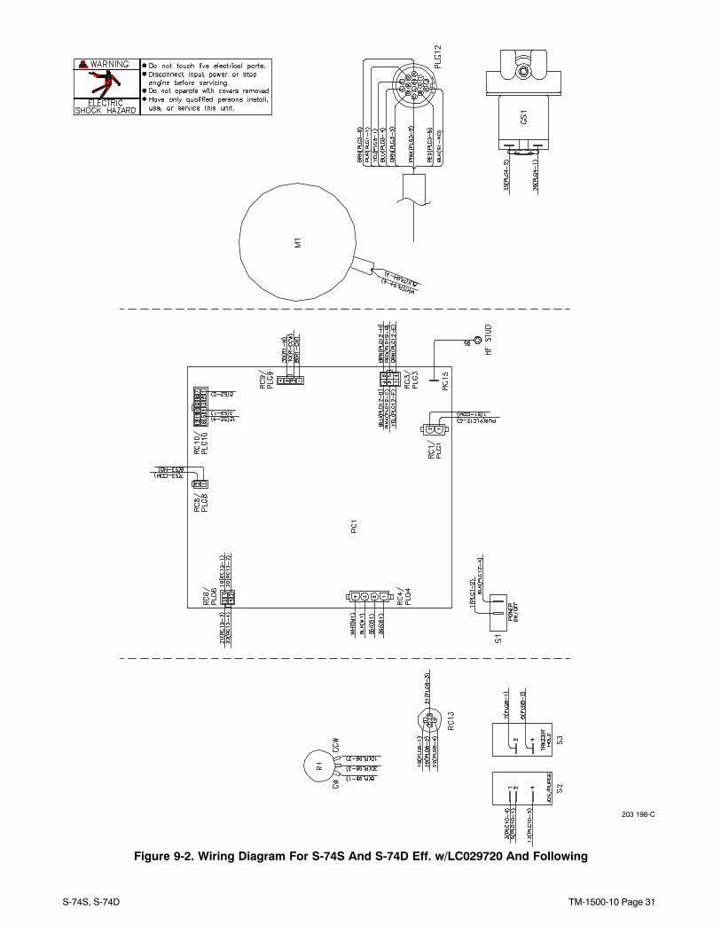
203 198-C
Figure 9-2. Wiring Diagram For S-74S And S-74D Eff. w/LC029720 And Following
TM-1500-10 Page 32 S-74S, S-74D
Figure 9-3. Circuit Diagram For Control Board PC1 Eff. w/LC029720 Thru LC713340 (Part 1 of 2)
TM-1500-10 Page 33S-74S, S-74D
204 009-E (1 0f 2)
TM-1500-10 Page 34 S-74S, S-74D
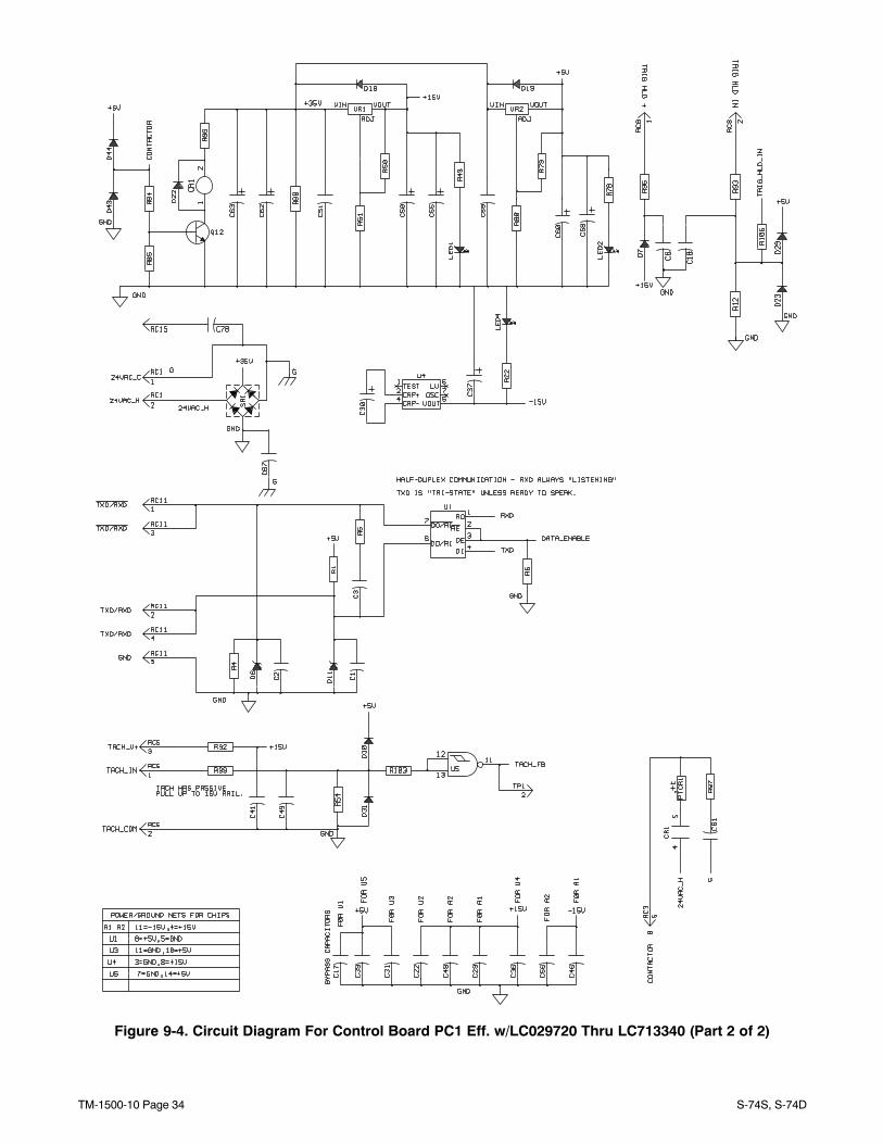
Figure 9-4. Circuit Diagram For Control Board PC1 Eff. w/LC029720 Thru LC713340 (Part 2 of 2)
TM-1500-10 Page 35S-74S, S-74D
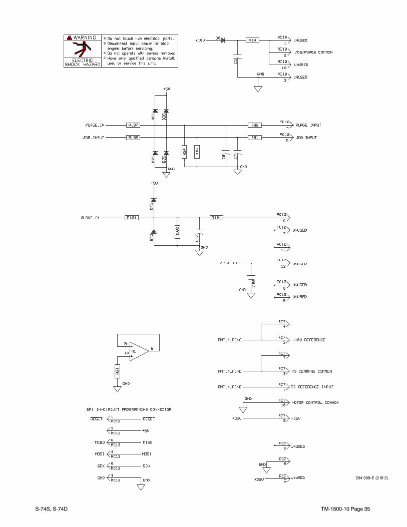
204 009-E (2 0f 2)
TM-1500-10 Page 36 S-74S, S-74D
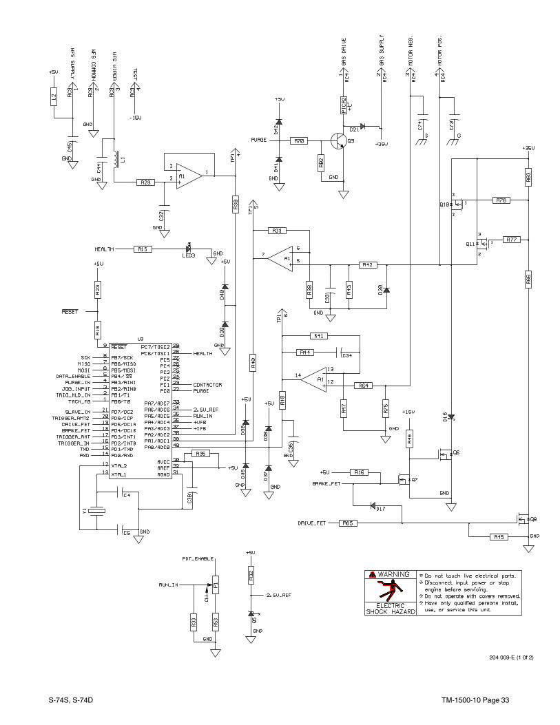
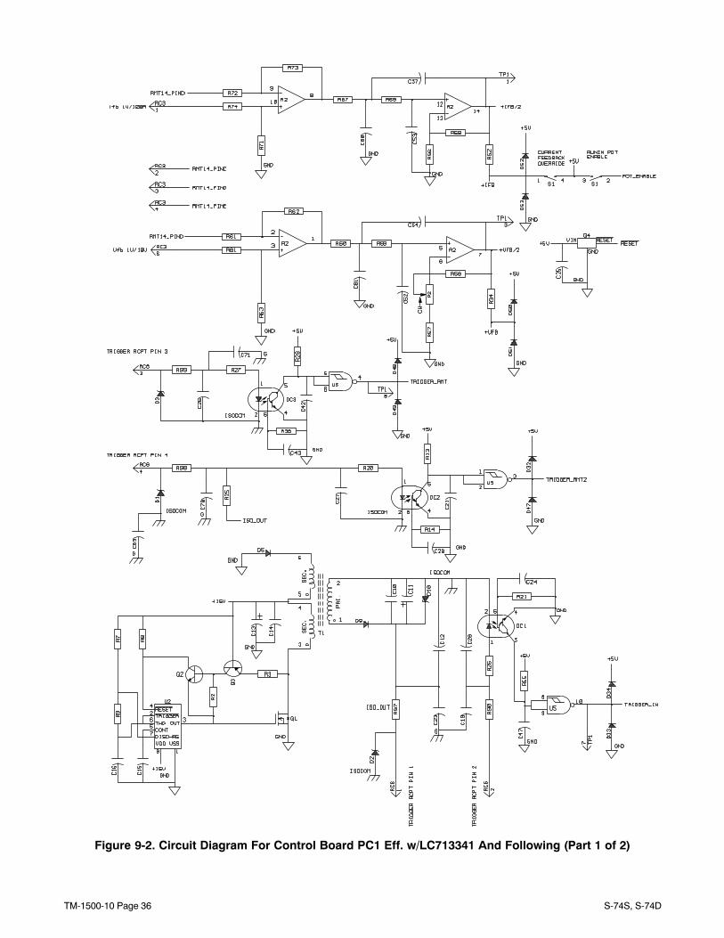
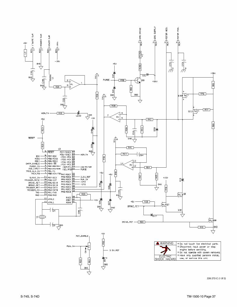
Figure 9-2. Circuit Diagram For Control Board PC1 Eff. w/LC713341 And Following (Part 1 of 2)
TM-1500-10 Page 37S-74S, S-74D
226 272-C (1 0f 2)
TM-1500-10 Page 38 S-74S, S-74D
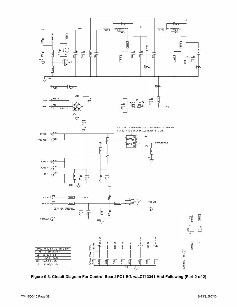
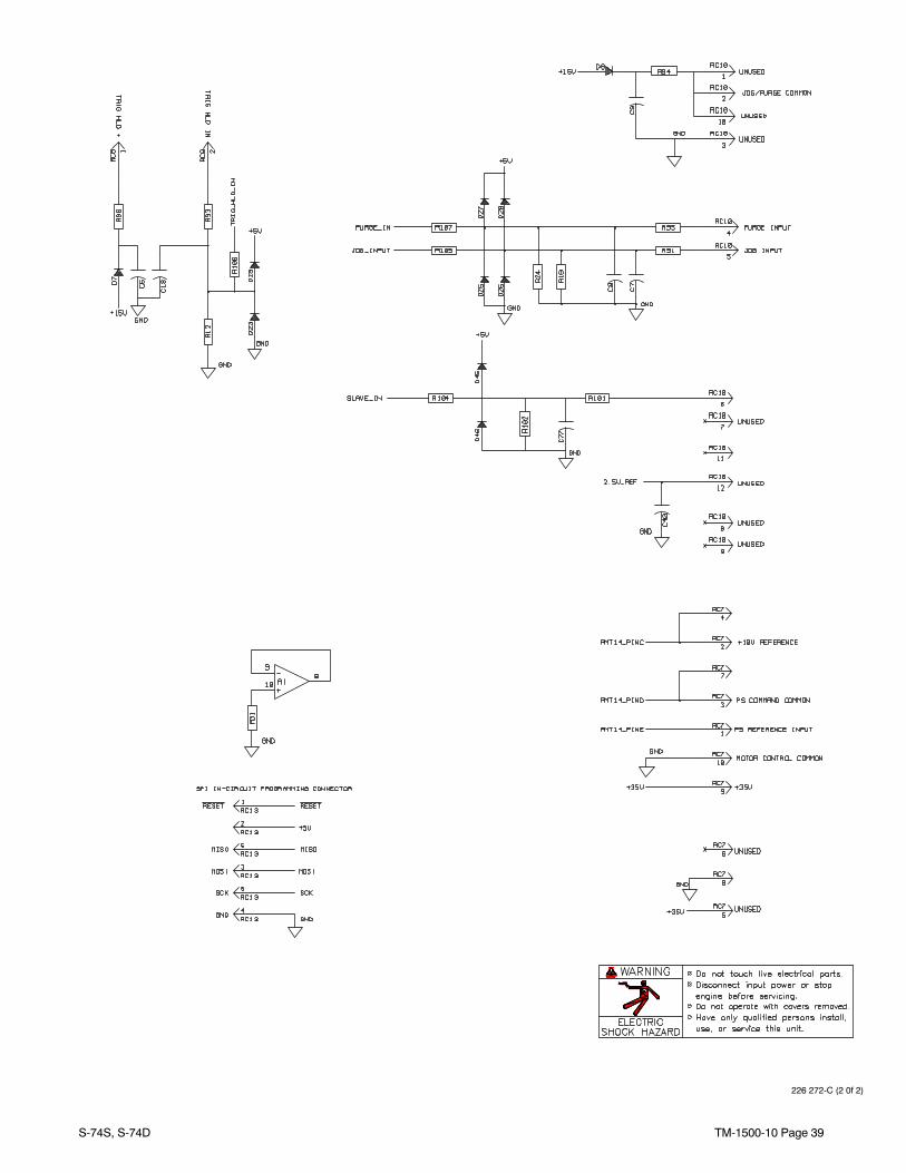
Figure 9-3. Circuit Diagram For Control Board PC1 Eff. w/LC713341 And Following (Part 2 of 2)
TM-1500-10 Page 39S-74S, S-74D
226 272-C (2 0f 2)
TM-1500-10 Page 40 S-74S, S-74D
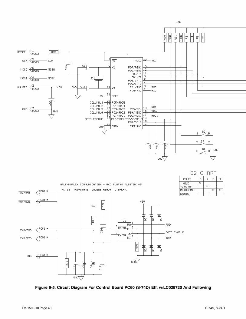
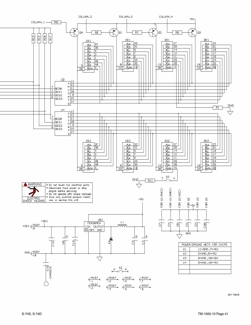
Figure 9-5. Circuit Diagram For Control Board PC60 (S-74D) Eff. w/LC029720 And Following
TM-1500-10 Page 41S-74S, S-74D
201 758-B

TM-1500-10 Page 42 S-74S, S-74D
Notes
Processes
Description
MIG (GMAW) Welding
Flux Cored (FCAW) Welding(Gas-and Self-Shielded)
Wire Feeder
S-74S, S-74D
Eff w/LC029720 THRU LC676743For OM-1500-10 (207 748) Revisions * Thru B
TM-1500-10D 2006−07
Visit our website at
www.MillerWelds.com
TM-1500-10 Page 44 S-74S, S-74D
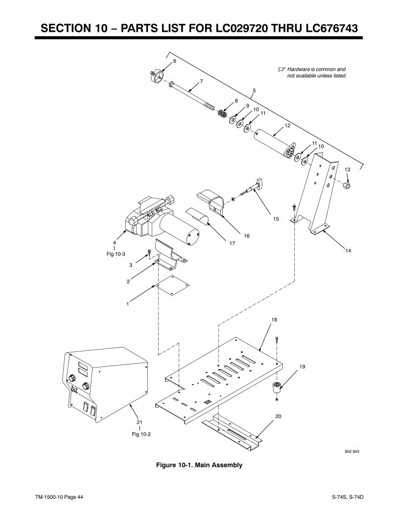
SECTION 10 − PARTS LIST FOR LC029720 THRU LC676743
802 943
� Hardware is common andnot available unless listed.
Fig 10-2
21
Fig 10-3
4
1
2
6
14
15
1617
18
19
20
5
7
89
1011
12
1110
13
3
Figure 10-1. Main Assembly
TM-1500-10 Page 45S-74S, S-74D
DescriptionPartNo.
ItemNo.
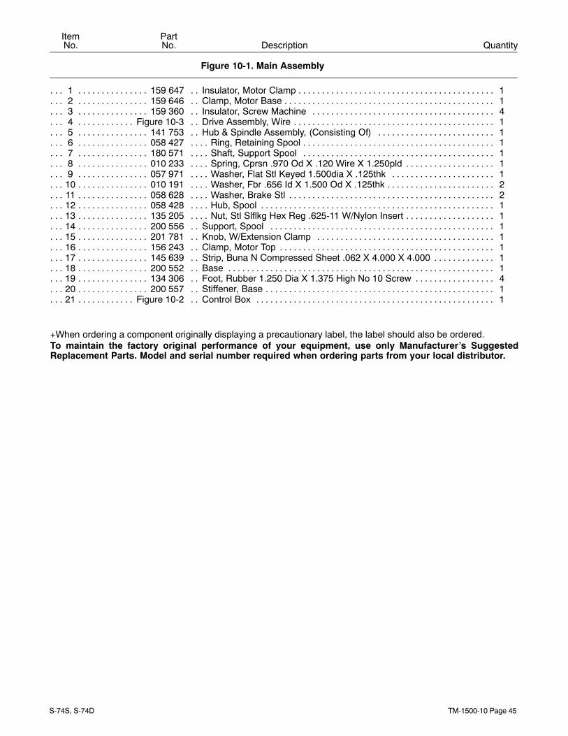
Figure 10-1. Main Assembly
Quantity
1 159 647 Insulator, Motor Clamp 1. . . . . . . . . . . . . . . . . . . . . . . . . . . . . . . . . . . . . . . . . . . . . . . . . . . . . . . . . . . . . . 2 159 646 Clamp, Motor Base 1. . . . . . . . . . . . . . . . . . . . . . . . . . . . . . . . . . . . . . . . . . . . . . . . . . . . . . . . . . . . . . . . . 3 159 360 Insulator, Screw Machine 4. . . . . . . . . . . . . . . . . . . . . . . . . . . . . . . . . . . . . . . . . . . . . . . . . . . . . . . . . . . 4 Figure 10-3 Drive Assembly, Wire 1. . . . . . . . . . . . . . . . . . . . . . . . . . . . . . . . . . . . . . . . . . . . . . . . . . . . . . . . . . . . 5 141 753 Hub & Spindle Assembly, (Consisting Of) 1. . . . . . . . . . . . . . . . . . . . . . . . . . . . . . . . . . . . . . . . . . . . . 6 058 427 Ring, Retaining Spool 1. . . . . . . . . . . . . . . . . . . . . . . . . . . . . . . . . . . . . . . . . . . . . . . . . . . . . . . . . . . . . . . 7 180 571 Shaft, Support Spool 1. . . . . . . . . . . . . . . . . . . . . . . . . . . . . . . . . . . . . . . . . . . . . . . . . . . . . . . . . . . . . . . 8 010 233 Spring, Cprsn .970 Od X .120 Wire X 1.250pld 1. . . . . . . . . . . . . . . . . . . . . . . . . . . . . . . . . . . . . . . . . 9 057 971 Washer, Flat Stl Keyed 1.500dia X .125thk 1. . . . . . . . . . . . . . . . . . . . . . . . . . . . . . . . . . . . . . . . . . . .
10 010 191 Washer, Fbr .656 Id X 1.500 Od X .125thk 2. . . . . . . . . . . . . . . . . . . . . . . . . . . . . . . . . . . . . . . . . . . . . 11 058 628 Washer, Brake Stl 2. . . . . . . . . . . . . . . . . . . . . . . . . . . . . . . . . . . . . . . . . . . . . . . . . . . . . . . . . . . . . . . . . . 12 058 428 Hub, Spool 1. . . . . . . . . . . . . . . . . . . . . . . . . . . . . . . . . . . . . . . . . . . . . . . . . . . . . . . . . . . . . . . . . . . . . . . . 13 135 205 Nut, Stl Slflkg Hex Reg .625-11 W/Nylon Insert 1. . . . . . . . . . . . . . . . . . . . . . . . . . . . . . . . . . . . . . . . . 14 200 556 Support, Spool 1. . . . . . . . . . . . . . . . . . . . . . . . . . . . . . . . . . . . . . . . . . . . . . . . . . . . . . . . . . . . . . . . . . . . 15 201 781 Knob, W/Extension Clamp 1. . . . . . . . . . . . . . . . . . . . . . . . . . . . . . . . . . . . . . . . . . . . . . . . . . . . . . . . . . 16 156 243 Clamp, Motor Top 1. . . . . . . . . . . . . . . . . . . . . . . . . . . . . . . . . . . . . . . . . . . . . . . . . . . . . . . . . . . . . . . . . . 17 145 639 Strip, Buna N Compressed Sheet .062 X 4.000 X 4.000 1. . . . . . . . . . . . . . . . . . . . . . . . . . . . . . . . . 18 200 552 Base 1. . . . . . . . . . . . . . . . . . . . . . . . . . . . . . . . . . . . . . . . . . . . . . . . . . . . . . . . . . . . . . . . . . . . . . . . . . . . . 19 134 306 Foot, Rubber 1.250 Dia X 1.375 High No 10 Screw 4. . . . . . . . . . . . . . . . . . . . . . . . . . . . . . . . . . . . . 20 200 557 Stiffener, Base 1. . . . . . . . . . . . . . . . . . . . . . . . . . . . . . . . . . . . . . . . . . . . . . . . . . . . . . . . . . . . . . . . . . . . . 21 Figure 10-2 Control Box 1. . . . . . . . . . . . . . . . . . . . . . . . . . . . . . . . . . . . . . . . . . . . . . . . . . . . . . . . . . . . . . . . . . . .
+When ordering a component originally displaying a precautionary label, the label should also be ordered.To maintain the factory original performance of your equipment, use only Manufacturer’s SuggestedReplacement Parts. Model and serial number required when ordering parts from your local distributor.
TM-1500-10 Page 46 S-74S, S-74D
802 945-A
� Hardware is common andnot available unless listed.
2
56 7 8
9 87 10
11
12
13
1415
16
1718
19
20
23
24
2526
27
22
28
4
21
3
1
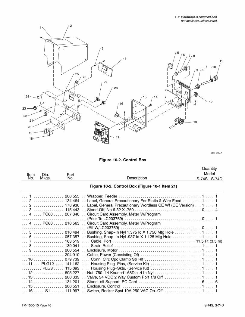
Figure 10-2. Control Box
Quantity
DescriptionPartNo.
Dia.Mkgs.
ItemNo.
ModelS-74S S-74D
Figure 10-2. Control Box (Figure 10-1 Item 21)
1 200 555 Wrapper, Feeder 1 1. . . . . . . . . . . . . . . . . . . . . . . . . . . . . . . . . . . . . . . . . . . . . . . . . . . . . . . . . . . . . . . . . 2 134 464 Label, General Precautionary For Static & Wire Feed 1 1. . . . . . . . . . . . . . . . . . . . . . . . . . . . . . . . . 2 178 936 Label, General Precautionary Wordless CE Wf (CE Version) 1 1. . . . . . . . . . . . . . . . . . . . . . . . . . . 3 115 443 Stand-Off, No 6-32 X .750 0 4. . . . . . . . . . . . . . . . . . . . . . . . . . . . . . . . . . . . . . . . . . . . . . . . . . . . . . . . . 4 PC60 207 340 Circuit Card Assembly, Meter W/Program . . . . . . . . . . . . . .
(Prior To LC203769) 0 1. . . . . . . . . . . . . . . . . . . . . . . . . . . . . . . . . . . . . . . . . . . . . . . . . . . . . . . . . . . . . . . . . . . . . . . . . . 4 PC60 210 563 Circuit Card Assembly, Meter W/Program . . . . . . . . . . . . . .
(Eff W/LC203769) 0 1. . . . . . . . . . . . . . . . . . . . . . . . . . . . . . . . . . . . . . . . . . . . . . . . . . . . . . . . . . . . . . . . . . . . . . . . . . . . 5 010 494 Bushing, Snap−In Nyl 1.375 Id X 1.750 Mtg Hole 1 1. . . . . . . . . . . . . . . . . . . . . . . . . . . . . . . . . . . . . 6 057 357 Bushing, Snap−In Nyl .937 Id X 1.125 Mtg Hole 1 1. . . . . . . . . . . . . . . . . . . . . . . . . . . . . . . . . . . . . . 7 163 519 Cable, Port 11.5 Ft (3.5 m). . . . . . . . . . . . . . . . . . . . . . . . . . . . . . . . . . . . . . . . . . . . . . . . . . . . . . . . . . . . . . . 8 139 041 Strain Relief 1 1. . . . . . . . . . . . . . . . . . . . . . . . . . . . . . . . . . . . . . . . . . . . . . . . . . . . . . . . . . . . . . . . . . . . . 9 200 554 Enclosure, Motor 1 1. . . . . . . . . . . . . . . . . . . . . . . . . . . . . . . . . . . . . . . . . . . . . . . . . . . . . . . . . . . . . . . . .
204 910 Cable, Power (Consisting Of) 1 1. . . . . . . . . . . . . . . . . . . . . . . . . . . . . . . . . . . . . . . . . . . . . . . . . . . . . . . . . 10 079 739 Conn, Circ Cpc Clamp Str Rlf 1 1. . . . . . . . . . . . . . . . . . . . . . . . . . . . . . . . . . . . . . . . . . . . . . . . . . . . . . 11 PLG12 141 162 Housing Plug+Pins, (Service Kit) 1 1. . . . . . . . . . . . . . . . . . . . . . . . . . . . . . . . . . . . . . . . . . .
PLG3 115 093 Housing Plug+Skts, (Service Kit) 1 1. . . . . . . . . . . . . . . . . . . . . . . . . . . . . . . . . . . . . . . . . . . . . . . . 12 605 227 Nut, 750−14 Knurled1.68Dia .41h Nyl 1 1. . . . . . . . . . . . . . . . . . . . . . . . . . . . . . . . . . . . . . . . . . . . . . . 13 200 333 Valve, 34 VDC 2 Way Custom Port 1/8 Orf 1 1. . . . . . . . . . . . . . . . . . . . . . . . . . . . . . . . . . . . . . . . . . 14 134 201 Stand−off Support, PC Card 6 6. . . . . . . . . . . . . . . . . . . . . . . . . . . . . . . . . . . . . . . . . . . . . . . . . . . . . . . 15 200 551 Enclosure, Control 1 1. . . . . . . . . . . . . . . . . . . . . . . . . . . . . . . . . . . . . . . . . . . . . . . . . . . . . . . . . . . . . . . 16 S1 111 997 Switch, Rocker Spst 10A 250 VAC On−Off 1 1. . . . . . . . . . . . . . . . . . . . . . . . . . . . . . . . . . . . . .
TM-1500-10 Page 47S-74S, S-74D
Quantity
DescriptionPartNo.
Dia.Mkgs.
ItemNo.
ModelS-74S S-74D
Figure 10-2. Control Box (Figure 10-1 Item 21)
17 PC1 207 344 Circuit Card Assy, Motor Control. . . . . . . . . . . . . . (Prior To LC203769) 1 1. . . . . . . . . . . . . . . . . . . . . . . . . . . . . . . . . . . . . . . . . . . . . . . . . . . . . . . . . . . . . . . . . . . . . . . . . .
17 PC1 210 555 Circuit Card Assy, Motor Control. . . . . . . . . . . . . . (Eff W/LC203769) 1 1. . . . . . . . . . . . . . . . . . . . . . . . . . . . . . . . . . . . . . . . . . . . . . . . . . . . . . . . . . . . . . . . . . . . . . . . . . . .
18 S2 200 295 Switch, Rocker Spdt 15A 12V (On)−Off−(On) 1 1. . . . . . . . . . . . . . . . . . . . . . . . . . . . . . . . . . . . 19 S3 201 642 Switch, Rocker Spdt 15A 12V On−None−On 1 1. . . . . . . . . . . . . . . . . . . . . . . . . . . . . . . . . . . . . 20 203 216 Nameplate, Lower 1 1. . . . . . . . . . . . . . . . . . . . . . . . . . . . . . . . . . . . . . . . . . . . . . . . . . . . . . . . . . . . . . . 20 206 296 Nameplate, Lower (CE Version) 1 1. . . . . . . . . . . . . . . . . . . . . . . . . . . . . . . . . . . . . . . . . . . . . . . . . . . . 21 171 007 Knob, Pointer 1.670 Dia X .250 Id W/Set Screwsplstc 0 1. . . . . . . . . . . . . . . . . . . . . . . . . . . . . . . . . 22 119 951 Blank, Snap-In Nyl .437 Mtg Hole Black 1 0. . . . . . . . . . . . . . . . . . . . . . . . . . . . . . . . . . . . . . . . . . . . . 23 171 007 Knob, Pointer 1.670 Dia X .250 Id W/Set Screwsplstc 1 1. . . . . . . . . . . . . . . . . . . . . . . . . . . . . . . . . 24 203 212 Nameplate, Upper 1 0. . . . . . . . . . . . . . . . . . . . . . . . . . . . . . . . . . . . . . . . . . . . . . . . . . . . . . . . . . . . . . . 24 206 432 Nameplate, Upper (CE Version) 1 0. . . . . . . . . . . . . . . . . . . . . . . . . . . . . . . . . . . . . . . . . . . . . . . . . . . . 24 203 214 Nameplate, Upper W/Meters 0 1. . . . . . . . . . . . . . . . . . . . . . . . . . . . . . . . . . . . . . . . . . . . . . . . . . . . . . 24 206 295 Nameplate, Upper W/Meters (CE Version) 0 1. . . . . . . . . . . . . . . . . . . . . . . . . . . . . . . . . . . . . . . . . . 24 203 216 Nameplate, Lower 1 1. . . . . . . . . . . . . . . . . . . . . . . . . . . . . . . . . . . . . . . . . . . . . . . . . . . . . . . . . . . . . . . 24 206 296 Nameplate, Lower (CE Version) 1 1. . . . . . . . . . . . . . . . . . . . . . . . . . . . . . . . . . . . . . . . . . . . . . . . . . . . 25 202 237 Panel, Front 1 1. . . . . . . . . . . . . . . . . . . . . . . . . . . . . . . . . . . . . . . . . . . . . . . . . . . . . . . . . . . . . . . . . . . . 26 RC13 048 282 Rcpt W/Skts, (Service Kit) 1 1. . . . . . . . . . . . . . . . . . . . . . . . . . . . . . . . . . . . . . . . . . . . . . . . . . .
PLG8 131 054 Housing Rcpt+Skts, (Service Kit) 1 1. . . . . . . . . . . . . . . . . . . . . . . . . . . . . . . . . . . . . . . . . . . . . . . . PLG9 201 665 Housing Plug+Skts, (Service Kit) 1 1. . . . . . . . . . . . . . . . . . . . . . . . . . . . . . . . . . . . . . . . . . . . . . . . PLG6 115 094 Housing Plug+Skts, (Service Kit) 1 1. . . . . . . . . . . . . . . . . . . . . . . . . . . . . . . . . . . . . . . . . . . . . . . . PLG1 202 592 Housing Plug Pins+Skts, (Service Kit) 1 1. . . . . . . . . . . . . . . . . . . . . . . . . . . . . . . . . . . . . . . . . . . PLG4 136 810 Housing Plug Pins+Skts, (Service Kit) 1 1. . . . . . . . . . . . . . . . . . . . . . . . . . . . . . . . . . . . . . . . . . .
PLG10 130 203 Housing Plug+Skts, (Service Kit) 1 1. . . . . . . . . . . . . . . . . . . . . . . . . . . . . . . . . . . . . . . . . . . . . . 27 R1 073 562 Potentiometer, Cp Std Slot 1T 2W 10K Linear 1 0. . . . . . . . . . . . . . . . . . . . . . . . . . . . . . . . . . . 27 R1 603 856 Potentiometer, Ww Sltd Sft 10/T 2W 10K Ohm 0 1. . . . . . . . . . . . . . . . . . . . . . . . . . . . . . . . . . . 28 R70 603 856 Potentiometer, Ww Sltd Sft 10/T 2W 10K Ohm 0 1. . . . . . . . . . . . . . . . . . . . . . . . . . . . . . . . .
PLG7,27 115 091 Housing Plug+Skts, (Service Kit) 0 1. . . . . . . . . . . . . . . . . . . . . . . . . . . . . . . . . . . . . . . . . . . . PLG11,61 131 055 Housing Plug+Skts, (Service Kit) 0 1. . . . . . . . . . . . . . . . . . . . . . . . . . . . . . . . . . . . . . . . . . . .
PLG17 158 719 Housing Plug+Skts, (Service Kit) 0 1. . . . . . . . . . . . . . . . . . . . . . . . . . . . . . . . . . . . . . . . . . . . . .
+When ordering a component originally displaying a precautionary label, the label should also be ordered.To maintain the factory original performance of your equipment, use only Manufacturer’s SuggestedReplacement Parts. Model and serial number required when ordering parts from your local distributor.
TM-1500-10 Page 48 S-74S, S-74D
See Table 10-1 For Drive Roll & Wire Guide Kits
� Hardware is common andnot available unless listed.
802 950-A
12
3 4 5 6 7 8
10
9
2324
65
43
2
1
25
262728
2930
313233
34
35
3637
38
39
16
1413
15
2212
11
21
1718
19
20
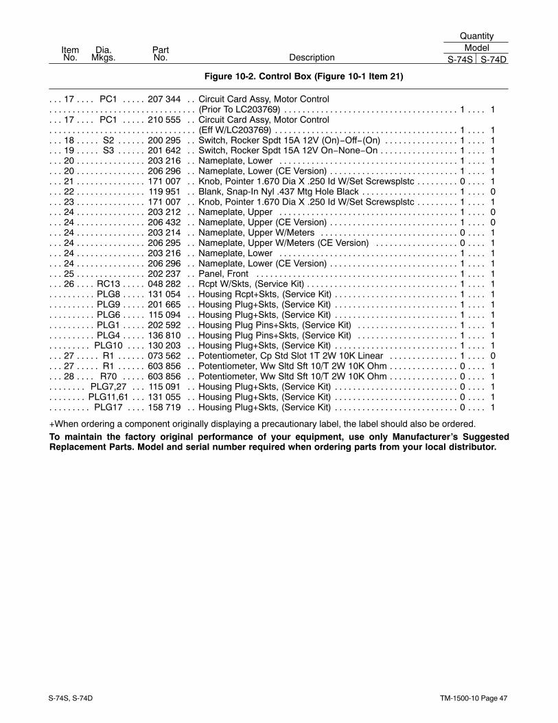
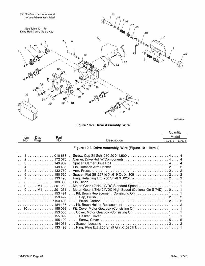
Figure 10-3. Drive Assembly, Wire
Quantity
DescriptionPartNo.
Dia.Mkgs.
ItemNo.
ModelS-74S S-74D
Figure 10-3. Drive Assembly, Wire (Figure 10-1 Item 4)
1 010 668 Screw, Cap Stl Sch .250-20 X 1.500 4 4. . . . . . . . . . . . . . . . . . . . . . . . . . . . . . . . . . . . . . . . . . . . . . . . 2 172 075 Carrier, Drive Roll W/Components 4 4. . . . . . . . . . . . . . . . . . . . . . . . . . . . . . . . . . . . . . . . . . . . . . . . . . 3 149 962 Spacer, Carrier Drive Roll 4 4. . . . . . . . . . . . . . . . . . . . . . . . . . . . . . . . . . . . . . . . . . . . . . . . . . . . . . . . . 4 149 486 Pin, Rotation Arm Rocker 2 2. . . . . . . . . . . . . . . . . . . . . . . . . . . . . . . . . . . . . . . . . . . . . . . . . . . . . . . . . 5 132 750 Arm, Pressure 2 2. . . . . . . . . . . . . . . . . . . . . . . . . . . . . . . . . . . . . . . . . . . . . . . . . . . . . . . . . . . . . . . . . . . 6 150 520 Spacer, Flat Stl .257 Id X .619 Od X .105 2 2. . . . . . . . . . . . . . . . . . . . . . . . . . . . . . . . . . . . . . . . . . . 7 133 493 Ring, Retaining Ext .250 Shaft X .025Thk 2 2. . . . . . . . . . . . . . . . . . . . . . . . . . . . . . . . . . . . . . . . . . . 8 133 350 Pin, Hinge 1 1. . . . . . . . . . . . . . . . . . . . . . . . . . . . . . . . . . . . . . . . . . . . . . . . . . . . . . . . . . . . . . . . . . . . . . 9 M1 201 230 Motor, Gear 1/8Hp 24VDC Standard Speed 1 1. . . . . . . . . . . . . . . . . . . . . . . . . . . . . . . . . . . . . 9 M1 201 231 Motor, Gear 1/8Hp 24VDC High Speed (Optional On S-74D) 0 1. . . . . . . . . . . . . . . . . . . . . . .
153 491 Kit, Brush Replacement (Consisting Of) 1 1. . . . . . . . . . . . . . . . . . . . . . . . . . . . . . . . . . . . . . . . . . . . . . . . 153 492 Cap, Brush 2 2. . . . . . . . . . . . . . . . . . . . . . . . . . . . . . . . . . . . . . . . . . . . . . . . . . . . . . . . . . . . . . . . . . . . . . . .
*153 493 Brush, Carbon 2 2. . . . . . . . . . . . . . . . . . . . . . . . . . . . . . . . . . . . . . . . . . . . . . . . . . . . . . . . . . . . . . . . . . . . 184 136 Kit, Brush Holder Replacement 1 2. . . . . . . . . . . . . . . . . . . . . . . . . . . . . . . . . . . . . . . . . . . . . . . . . . . . . . .
10 155 098 Kit, Cover Motor Gearbox (Consisting Of) 1 1. . . . . . . . . . . . . . . . . . . . . . . . . . . . . . . . . . . . . . . . . . . 153 550 Cover, Motor Gearbox (Consisting Of) 1 1. . . . . . . . . . . . . . . . . . . . . . . . . . . . . . . . . . . . . . . . . . . . . . . . . 155 099 Gasket, Cover 1 1. . . . . . . . . . . . . . . . . . . . . . . . . . . . . . . . . . . . . . . . . . . . . . . . . . . . . . . . . . . . . . . . . . . . . 155 100 Screw, Cover 5 5. . . . . . . . . . . . . . . . . . . . . . . . . . . . . . . . . . . . . . . . . . . . . . . . . . . . . . . . . . . . . . . . . . . . . . 154 031 Spacer, Locating 2 2. . . . . . . . . . . . . . . . . . . . . . . . . . . . . . . . . . . . . . . . . . . . . . . . . . . . . . . . . . . . . . . . . . . . 133 493 Ring, Rtng Ext .250 Shaft Grv X .025Thk 1 1. . . . . . . . . . . . . . . . . . . . . . . . . . . . . . . . . . . . . . . . . . . . . . .
TM-1500-10 Page 49S-74S, S-74D
Quantity
DescriptionPartNo.
Dia.Mkgs.
ItemNo.
ModelS-74S S-74D
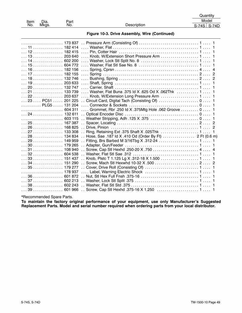
Figure 10-3. Drive Assembly, Wire (Continued)
173 837 Pressure Arm (Consisting Of) 1 1. . . . . . . . . . . . . . . . . . . . . . . . . . . . . . . . . . . . . . . . . . . . . . . . . . . . . . . . . 11 182 414 Washer, Flat 1 1. . . . . . . . . . . . . . . . . . . . . . . . . . . . . . . . . . . . . . . . . . . . . . . . . . . . . . . . . . . . . . . . . . . . . 12 182 415 Pin, Cotter Hair 1 1. . . . . . . . . . . . . . . . . . . . . . . . . . . . . . . . . . . . . . . . . . . . . . . . . . . . . . . . . . . . . . . . . . 13 203 640 Knob, W/Extension Short Pressure Arm 1 1. . . . . . . . . . . . . . . . . . . . . . . . . . . . . . . . . . . . . . . . . . . . . 14 602 200 Washer, Lock Stl Split No. 8 1 1. . . . . . . . . . . . . . . . . . . . . . . . . . . . . . . . . . . . . . . . . . . . . . . . . . . . . . . 15 604 772 Washer, Flat Stl Sae No. 8 1 1. . . . . . . . . . . . . . . . . . . . . . . . . . . . . . . . . . . . . . . . . . . . . . . . . . . . . . . . 16 182 156 Spring, Cprsn 4 4. . . . . . . . . . . . . . . . . . . . . . . . . . . . . . . . . . . . . . . . . . . . . . . . . . . . . . . . . . . . . . . . . . . . 17 182 155 Spring 2 2. . . . . . . . . . . . . . . . . . . . . . . . . . . . . . . . . . . . . . . . . . . . . . . . . . . . . . . . . . . . . . . . . . . . . . . . . . 18 132 746 Bushing, Spring 2 2. . . . . . . . . . . . . . . . . . . . . . . . . . . . . . . . . . . . . . . . . . . . . . . . . . . . . . . . . . . . . . . . . . 19 203 633 Shaft, Spring 1 1. . . . . . . . . . . . . . . . . . . . . . . . . . . . . . . . . . . . . . . . . . . . . . . . . . . . . . . . . . . . . . . . . . . . 20 132 747 Carrier, Shaft 1 1. . . . . . . . . . . . . . . . . . . . . . . . . . . . . . . . . . . . . . . . . . . . . . . . . . . . . . . . . . . . . . . . . . . . 21 133 739 Washer, Flat Buna .375 Id X .625 Od X .062Thk 1 1. . . . . . . . . . . . . . . . . . . . . . . . . . . . . . . . . . . . . 22 203 637 Knob, W/Extension Long Pressure Arm 1 1. . . . . . . . . . . . . . . . . . . . . . . . . . . . . . . . . . . . . . . . . . . . . 23 PC51 201 225 Circuit Card, Digital Tach (Consisting Of) 0 1. . . . . . . . . . . . . . . . . . . . . . . . . . . . . . . . . . . . . .
PLG5 131 204 Connector & Sockets 0 1. . . . . . . . . . . . . . . . . . . . . . . . . . . . . . . . . . . . . . . . . . . . . . . . . . . . . . . . . . 604 311 Grommet, Rbr .250 Id X .375Mtg Hole .062 Groove 0 1. . . . . . . . . . . . . . . . . . . . . . . . . . . . . . . . . . . . . .
24 132 611 Optical Encoder Disc 0 1. . . . . . . . . . . . . . . . . . . . . . . . . . . . . . . . . . . . . . . . . . . . . . . . . . . . . . . . . . . . . 603 115 Weather Stripping, Adh .125 X .375 0 1. . . . . . . . . . . . . . . . . . . . . . . . . . . . . . . . . . . . . . . . . . . . . . . . . . .
25 167 387 Spacer, Locating 2 2. . . . . . . . . . . . . . . . . . . . . . . . . . . . . . . . . . . . . . . . . . . . . . . . . . . . . . . . . . . . . . . . . 26 168 825 Drive, Pinion 1 2. . . . . . . . . . . . . . . . . . . . . . . . . . . . . . . . . . . . . . . . . . . . . . . . . . . . . . . . . . . . . . . . . . . . 27 133 308 Ring, Retaining Ext .375 Shaft X .025Thk 1 1. . . . . . . . . . . . . . . . . . . . . . . . . . . . . . . . . . . . . . . . . . . 28 134 834 Hose, Sae .187 Id X .410 Od (Order By Ft) 2 Ft (0.6 m). . . . . . . . . . . . . . . . . . . . . . . . . . . . . . . . . . . . 29 149 959 Fitting, Brs Barbed M 3/16Tbg X .312-24 1 1. . . . . . . . . . . . . . . . . . . . . . . . . . . . . . . . . . . . . . . . . . . . 30 179 265 Adapter, Gun/Feeder 1 1. . . . . . . . . . . . . . . . . . . . . . . . . . . . . . . . . . . . . . . . . . . . . . . . . . . . . . . . . . . . . 31 108 940 Screw, Cap Stl Hexhd .250-20 X .750 4 4. . . . . . . . . . . . . . . . . . . . . . . . . . . . . . . . . . . . . . . . . . . . . . . 32 604 538 Washer, Flat Stl Sae .312 1 1. . . . . . . . . . . . . . . . . . . . . . . . . . . . . . . . . . . . . . . . . . . . . . . . . . . . . . . . . 33 151 437 Knob, Plstc T 1.125 Lg X .312-18 X 1.500 1 1. . . . . . . . . . . . . . . . . . . . . . . . . . . . . . . . . . . . . . . . . . . 34 151 290 Screw, Mach Stl Hexwhd 10-32 X .500 2 2. . . . . . . . . . . . . . . . . . . . . . . . . . . . . . . . . . . . . . . . . . . . . . 35 179 277 Cover, Drive Roll (Consisting Of) 1 1. . . . . . . . . . . . . . . . . . . . . . . . . . . . . . . . . . . . . . . . . . . . . . . . . . .
178 937 Label, Warning Electric Shock 1 1. . . . . . . . . . . . . . . . . . . . . . . . . . . . . . . . . . . . . . . . . . . . . . . . . . . . . . . . 36 601 872 Nut, Stl Hex Full Fnsh .375-16 1 1. . . . . . . . . . . . . . . . . . . . . . . . . . . . . . . . . . . . . . . . . . . . . . . . . . . . . 37 602 213 Washer, Lock Stl Split .375 1 1. . . . . . . . . . . . . . . . . . . . . . . . . . . . . . . . . . . . . . . . . . . . . . . . . . . . . . . . 38 602 243 Washer, Flat Stl Std .375 1 1. . . . . . . . . . . . . . . . . . . . . . . . . . . . . . . . . . . . . . . . . . . . . . . . . . . . . . . . . . 39 601 966 Screw, Cap Stl Hexhd .375-16 X 1.250 1 1. . . . . . . . . . . . . . . . . . . . . . . . . . . . . . . . . . . . . . . . . . . . .
*Recommended Spare Parts.To maintain the factory original performance of your equipment, use only Manufacturer’s SuggestedReplacement Parts. Model and serial number required when ordering parts from your local distributor.
TM-1500-10 Page 50 S-74S, S-74D
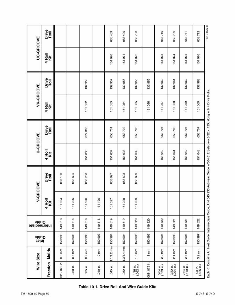
Table 10-1. Drive Roll And Wire Guide Kits
.023
-.02
5 in
.0.
6 m
m15
1 02
408
7 13
0
.030
in.
0.8
mm
151
025
053
695
.035
in.
0.9
mm
151
026
053
700
151
036
072
000
151
052
132
958
.045
in.
1.1/
1.2
mm
151
027
053
697
151
037
053
701
151
053
132
957
151
070
083
489
.052
in.
1.3/
1.4
mm
151
028
053
698
151
038
053
702
151
054
132
956
151
071
083
490
1/16
in.
1.6
mm
151
029
053
699
151
039
053
706
151
055
132
955
151
072
053
708
(.06
2 in
.)
.068
-.07
2 in
.1.
8 m
m15
1 05
613
2 95
9
5/64
in.
2.0
mm
151
040
053
704
151
057
132
960
151
073
053
710
(.07
9 in
.)
3/32
in.
(.09
4 in
.)2.
4 m
m15
1 04
105
3 70
315
1 05
813
2 96
115
1 07
405
3 70
9
7/64
in.
(.11
0 in
.)2.
8 m
m15
1 04
205
3 70
513
2 96
215
1 07
505
3 71
115
1 05
9
1/8
in.
(.12
5 in
.)3.
2 m
m15
1 04
305
3 70
715
1 06
013
2 96
315
1 07
605
3 71
2
Fra
ctio
nM
etri
c
Wir
e S
ize
V-G
RO
OV
E
4 R
oll
U-G
RO
OV
EV
K-G
RO
OV
EU
C-G
RO
OV
E
Dri
veR
oll
4 R
oll
Dri
veR
oll
4 R
oll
Dri
veR
oll
4 R
oll
Dri
veR
oll
Eac
h K
it C
onta
ins
An
Inle
t Gui
de, I
nter
med
iate
Gui
de, A
nd 0
45 2
33 A
ntiw
ear
Gui
de w
/604
612
Set
scre
w 8
-32
x .1
25, a
long
with
4 D
rive
Rol
ls.
InletGuide
150
993
150
993
150
993
150
994
150
994
150
995
150
995
150
995
150
996
150
996
150
997
IntermediateGuide
149
518
149
518
149
518
149
519
149
519
149
520
149
520
149
520
149
521
149
521
149
522
Kit
Kit
Kit
Kit
.040
in.
1.0
mm
161
190
150
993
149
518
Ref
. S-0
527-
C
Processes
Description
MIG (GMAW) Welding
Flux Cored (FCAW) Welding(Gas-and Self-Shielded)
Wire Feeder
S-74S, S-74D
Eff w/LC676744 AND FOLLOWINGFor OM-1500-10 (207 748) Revisions C Thru L
TM-1500-10D 2006−07
Visit our website at
www.MillerWelds.com
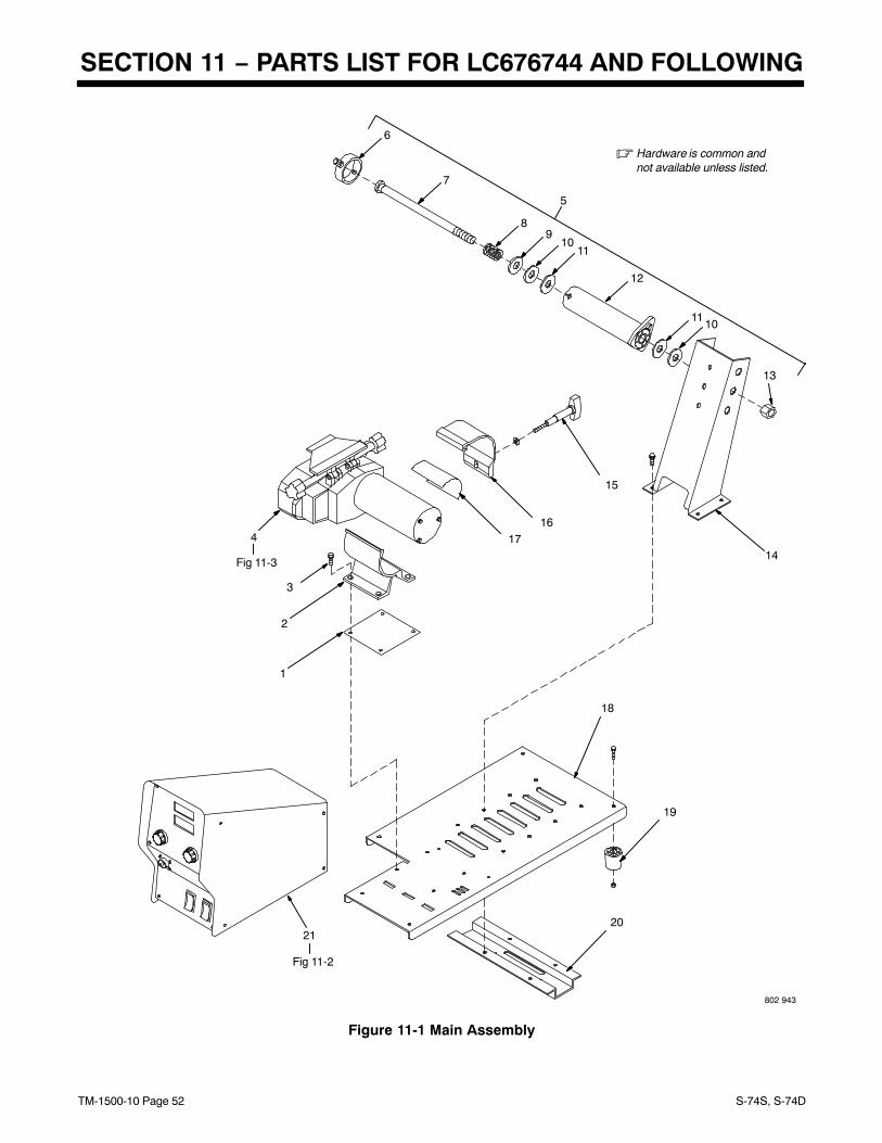
TM-1500-10 Page 52 S-74S, S-74D
SECTION 11 − PARTS LIST FOR LC676744 AND FOLLOWING
802 943
� Hardware is common andnot available unless listed.
Fig 11-2
21
Fig 11-3
4
1
2
6
14
15
1617
18
19
20
5
7
89
1011
12
1110
13
3
Figure 11-1 Main Assembly
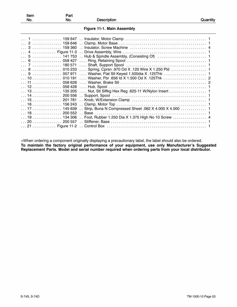
TM-1500-10 Page 53S-74S, S-74D
ItemNo.ItemNo.
PartNo. Description Quantity
Figure 11-1. Main Assembly
PartNo. Description Quantity
1 159 647 Insulator, Motor Clamp 1. . . . . . . . . . . . . . . . . . . . . . . . . . . . . . . . . . . . . . . . . . . . . . . . . . . . . . . . . . . . . . 2 159 646 Clamp, Motor Base 1. . . . . . . . . . . . . . . . . . . . . . . . . . . . . . . . . . . . . . . . . . . . . . . . . . . . . . . . . . . . . . . . . 3 159 360 Insulator, Screw Machine 4. . . . . . . . . . . . . . . . . . . . . . . . . . . . . . . . . . . . . . . . . . . . . . . . . . . . . . . . . . . 4 Figure 11-3 Drive Assembly, Wire 1. . . . . . . . . . . . . . . . . . . . . . . . . . . . . . . . . . . . . . . . . . . . . . . . . . . . . . . . . . . . 5 141 753 Hub & Spindle Assembly, (Consisting Of) 1. . . . . . . . . . . . . . . . . . . . . . . . . . . . . . . . . . . . . . . . . . . . . 6 058 427 Ring, Retaining Spool 1. . . . . . . . . . . . . . . . . . . . . . . . . . . . . . . . . . . . . . . . . . . . . . . . . . . . . . . . . . . . . . . 7 180 571 Shaft, Support Spool 1. . . . . . . . . . . . . . . . . . . . . . . . . . . . . . . . . . . . . . . . . . . . . . . . . . . . . . . . . . . . . . . 8 010 233 Spring, Cprsn .970 Od X .120 Wire X 1.250 Pld 1. . . . . . . . . . . . . . . . . . . . . . . . . . . . . . . . . . . . . . . . 9 057 971 Washer, Flat Stl Keyed 1.500dia X .125Thk 1. . . . . . . . . . . . . . . . . . . . . . . . . . . . . . . . . . . . . . . . . . . .
10 010 191 Washer, Fbr .656 Id X 1.500 Od X .125Thk 2. . . . . . . . . . . . . . . . . . . . . . . . . . . . . . . . . . . . . . . . . . . . 11 058 628 Washer, Brake Stl 2. . . . . . . . . . . . . . . . . . . . . . . . . . . . . . . . . . . . . . . . . . . . . . . . . . . . . . . . . . . . . . . . . . 12 058 428 Hub, Spool 1. . . . . . . . . . . . . . . . . . . . . . . . . . . . . . . . . . . . . . . . . . . . . . . . . . . . . . . . . . . . . . . . . . . . . . . . 13 135 205 Nut, Stl Slflkg Hex Reg .625-11 W/Nylon Insert 1. . . . . . . . . . . . . . . . . . . . . . . . . . . . . . . . . . . . . . . . . 14 200 556 Support, Spool 1. . . . . . . . . . . . . . . . . . . . . . . . . . . . . . . . . . . . . . . . . . . . . . . . . . . . . . . . . . . . . . . . . . . . 15 201 781 Knob, W/Extension Clamp 1. . . . . . . . . . . . . . . . . . . . . . . . . . . . . . . . . . . . . . . . . . . . . . . . . . . . . . . . . . 16 156 243 Clamp, Motor Top 1. . . . . . . . . . . . . . . . . . . . . . . . . . . . . . . . . . . . . . . . . . . . . . . . . . . . . . . . . . . . . . . . . . 17 145 639 Strip, Buna N Compressed Sheet .062 X 4.000 X 4.000 1. . . . . . . . . . . . . . . . . . . . . . . . . . . . . . . . . 18 200 552 Base 1. . . . . . . . . . . . . . . . . . . . . . . . . . . . . . . . . . . . . . . . . . . . . . . . . . . . . . . . . . . . . . . . . . . . . . . . . . . . . 19 134 306 Foot, Rubber 1.250 Dia X 1.375 High No 10 Screw 4. . . . . . . . . . . . . . . . . . . . . . . . . . . . . . . . . . . . . 20 200 557 Stiffener, Base 1. . . . . . . . . . . . . . . . . . . . . . . . . . . . . . . . . . . . . . . . . . . . . . . . . . . . . . . . . . . . . . . . . . . . . 21 Figure 11-2 Control Box 1. . . . . . . . . . . . . . . . . . . . . . . . . . . . . . . . . . . . . . . . . . . . . . . . . . . . . . . . . . . . . . . . . . . .
+When ordering a component originally displaying a precautionary label, the label should also be ordered.To maintain the factory original performance of your equipment, use only Manufacturer’s SuggestedReplacement Parts. Model and serial number required when ordering parts from your local distributor.
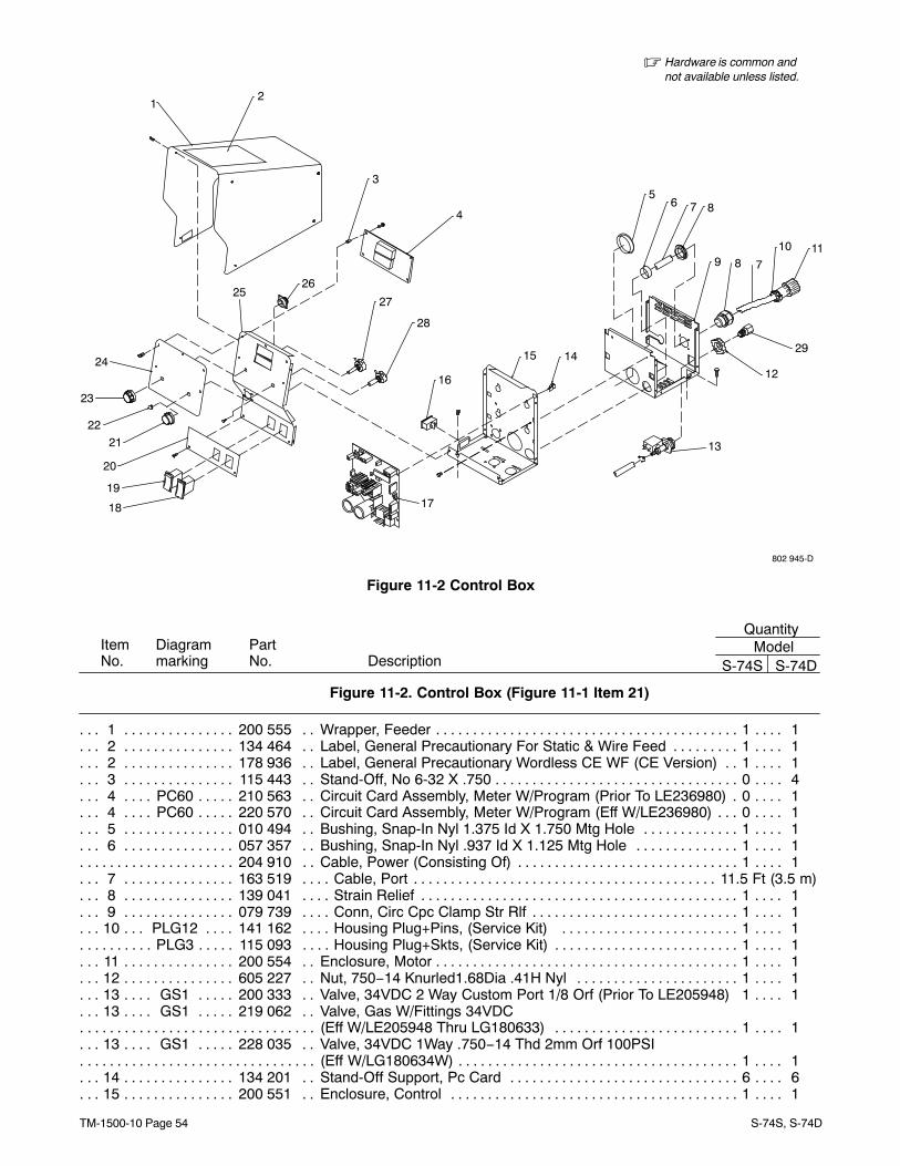
TM-1500-10 Page 54 S-74S, S-74D
802 945-D
� Hardware is common andnot available unless listed.
2
56 7 8
9 8 7
10 11
12
13
1415
16
1718
19
20
23
24
2526
27
22
28
4
21
3
1
29
Figure 11-2 Control Box
ItemNo. S-74S S-74D
Figure 11-2. Control Box (Figure 11-1 Item 21)
Diagrammarking
PartNo. Description
QuantityModel
1 200 555 Wrapper, Feeder 1 1. . . . . . . . . . . . . . . . . . . . . . . . . . . . . . . . . . . . . . . . . . . . . . . . . . . . . . . . . . . . . . . . . 2 134 464 Label, General Precautionary For Static & Wire Feed 1 1. . . . . . . . . . . . . . . . . . . . . . . . . . . . . . . . . 2 178 936 Label, General Precautionary Wordless CE WF (CE Version) 1 1. . . . . . . . . . . . . . . . . . . . . . . . . . 3 115 443 Stand-Off, No 6-32 X .750 0 4. . . . . . . . . . . . . . . . . . . . . . . . . . . . . . . . . . . . . . . . . . . . . . . . . . . . . . . . . 4 PC60 210 563 Circuit Card Assembly, Meter W/Program (Prior To LE236980) 0 1. . . . . . . . . . . . . . . . . . . 4 PC60 220 570 Circuit Card Assembly, Meter W/Program (Eff W/LE236980) 0 1. . . . . . . . . . . . . . . . . . . . . 5 010 494 Bushing, Snap-In Nyl 1.375 Id X 1.750 Mtg Hole 1 1. . . . . . . . . . . . . . . . . . . . . . . . . . . . . . . . . . . . . 6 057 357 Bushing, Snap-In Nyl .937 Id X 1.125 Mtg Hole 1 1. . . . . . . . . . . . . . . . . . . . . . . . . . . . . . . . . . . . . .
204 910 Cable, Power (Consisting Of) 1 1. . . . . . . . . . . . . . . . . . . . . . . . . . . . . . . . . . . . . . . . . . . . . . . . . . . . . . . . . 7 163 519 Cable, Port 11.5 Ft (3.5 m). . . . . . . . . . . . . . . . . . . . . . . . . . . . . . . . . . . . . . . . . . . . . . . . . . . . . . . . . . . . . . . 8 139 041 Strain Relief 1 1. . . . . . . . . . . . . . . . . . . . . . . . . . . . . . . . . . . . . . . . . . . . . . . . . . . . . . . . . . . . . . . . . . . . . 9 079 739 Conn, Circ Cpc Clamp Str Rlf 1 1. . . . . . . . . . . . . . . . . . . . . . . . . . . . . . . . . . . . . . . . . . . . . . . . . . . . . .
10 PLG12 141 162 Housing Plug+Pins, (Service Kit) 1 1. . . . . . . . . . . . . . . . . . . . . . . . . . . . . . . . . . . . . . . . . . PLG3 115 093 Housing Plug+Skts, (Service Kit) 1 1. . . . . . . . . . . . . . . . . . . . . . . . . . . . . . . . . . . . . . . . . . . . . . . .
11 200 554 Enclosure, Motor 1 1. . . . . . . . . . . . . . . . . . . . . . . . . . . . . . . . . . . . . . . . . . . . . . . . . . . . . . . . . . . . . . . . . 12 605 227 Nut, 750−14 Knurled1.68Dia .41H Nyl 1 1. . . . . . . . . . . . . . . . . . . . . . . . . . . . . . . . . . . . . . . . . . . . . . 13 GS1 200 333 Valve, 34VDC 2 Way Custom Port 1/8 Orf (Prior To LE205948) 1 1. . . . . . . . . . . . . . . . . . 13 GS1 219 062 Valve, Gas W/Fittings 34VDC . . . . . . . . . . . . . .
(Eff W/LE205948 Thru LG180633) 1 1. . . . . . . . . . . . . . . . . . . . . . . . . . . . . . . . . . . . . . . . . . . . . . . . . . . . . . . . . . . . . 13 GS1 228 035 Valve, 34VDC 1Way .750−14 Thd 2mm Orf 100PSI . . . . . . . . . . . . . .
(Eff W/LG180634W) 1 1. . . . . . . . . . . . . . . . . . . . . . . . . . . . . . . . . . . . . . . . . . . . . . . . . . . . . . . . . . . . . . . . . . . . . . . . . . 14 134 201 Stand-Off Support, Pc Card 6 6. . . . . . . . . . . . . . . . . . . . . . . . . . . . . . . . . . . . . . . . . . . . . . . . . . . . . . . 15 200 551 Enclosure, Control 1 1. . . . . . . . . . . . . . . . . . . . . . . . . . . . . . . . . . . . . . . . . . . . . . . . . . . . . . . . . . . . . . .
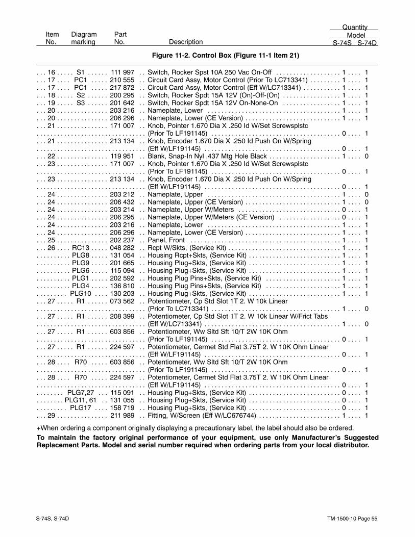
TM-1500-10 Page 55S-74S, S-74D
ItemNo.
Diagrammarking
PartNo. Description
QuantityModel
S-74S S-74D
Figure 11-2. Control Box (Figure 11-1 Item 21)
16 S1 111 997 Switch, Rocker Spst 10A 250 Vac On-Off 1 1. . . . . . . . . . . . . . . . . . . . . . . . . . . . . . . . . . . . . . . 17 PC1 210 555 Circuit Card Assy, Motor Control (Prior To LC713341) 1 1. . . . . . . . . . . . . . . . . . . . . . . . . . . 17 PC1 217 872 Circuit Card Assy, Motor Control (Eff W/LC713341) 1 1. . . . . . . . . . . . . . . . . . . . . . . . . . . . . 18 S2 200 295 Switch, Rocker Spdt 15A 12V (On)-Off-(On) 1 1. . . . . . . . . . . . . . . . . . . . . . . . . . . . . . . . . . . . . 19 S3 201 642 Switch, Rocker Spdt 15A 12V On-None-On 1 1. . . . . . . . . . . . . . . . . . . . . . . . . . . . . . . . . . . . . 20 203 216 Nameplate, Lower 1 1. . . . . . . . . . . . . . . . . . . . . . . . . . . . . . . . . . . . . . . . . . . . . . . . . . . . . . . . . . . . . . . 20 206 296 Nameplate, Lower (CE Version) 1 1. . . . . . . . . . . . . . . . . . . . . . . . . . . . . . . . . . . . . . . . . . . . . . . . . . . . 21 171 007 Knob, Pointer 1.670 Dia X .250 Id W/Set Screwsplstc . . . . . . . . . . . . . . . . . . . .
(Prior To LF191145) 0 1. . . . . . . . . . . . . . . . . . . . . . . . . . . . . . . . . . . . . . . . . . . . . . . . . . . . . . . . . . . . . . . . . . . . . . . . . . 21 213 134 Knob, Encoder 1.670 Dia X .250 Id Push On W/Spring . . . . . . . . . . . . . . . . . . . .
(Eff W/LF191145) 0 1. . . . . . . . . . . . . . . . . . . . . . . . . . . . . . . . . . . . . . . . . . . . . . . . . . . . . . . . . . . . . . . . . . . . . . . . . . . . 22 119 951 Blank, Snap-In Nyl .437 Mtg Hole Black 1 0. . . . . . . . . . . . . . . . . . . . . . . . . . . . . . . . . . . . . . . . . . . . . 23 171 007 Knob, Pointer 1.670 Dia X .250 Id W/Set Screwsplstc . . . . . . . . . . . . . . . . . . . .
(Prior To LF191145) 0 1. . . . . . . . . . . . . . . . . . . . . . . . . . . . . . . . . . . . . . . . . . . . . . . . . . . . . . . . . . . . . . . . . . . . . . . . . . 23 213 134 Knob, Encoder 1.670 Dia X .250 Id Push On W/Spring . . . . . . . . . . . . . . . . . . . .
(Eff W/LF191145) 0 1. . . . . . . . . . . . . . . . . . . . . . . . . . . . . . . . . . . . . . . . . . . . . . . . . . . . . . . . . . . . . . . . . . . . . . . . . . . . 24 203 212 Nameplate, Upper 1 0. . . . . . . . . . . . . . . . . . . . . . . . . . . . . . . . . . . . . . . . . . . . . . . . . . . . . . . . . . . . . . . 24 206 432 Nameplate, Upper (CE Version) 1 0. . . . . . . . . . . . . . . . . . . . . . . . . . . . . . . . . . . . . . . . . . . . . . . . . . . . 24 203 214 Nameplate, Upper W/Meters 0 1. . . . . . . . . . . . . . . . . . . . . . . . . . . . . . . . . . . . . . . . . . . . . . . . . . . . . . 24 206 295 Nameplate, Upper W/Meters (CE Version) 0 1. . . . . . . . . . . . . . . . . . . . . . . . . . . . . . . . . . . . . . . . . . 24 203 216 Nameplate, Lower 1 1. . . . . . . . . . . . . . . . . . . . . . . . . . . . . . . . . . . . . . . . . . . . . . . . . . . . . . . . . . . . . . . 24 206 296 Nameplate, Lower (CE Version) 1 1. . . . . . . . . . . . . . . . . . . . . . . . . . . . . . . . . . . . . . . . . . . . . . . . . . . . 25 202 237 Panel, Front 1 1. . . . . . . . . . . . . . . . . . . . . . . . . . . . . . . . . . . . . . . . . . . . . . . . . . . . . . . . . . . . . . . . . . . . 26 RC13 048 282 Rcpt W/Skts, (Service Kit) 1 1. . . . . . . . . . . . . . . . . . . . . . . . . . . . . . . . . . . . . . . . . . . . . . . . . . .
PLG8 131 054 Housing Rcpt+Skts, (Service Kit) 1 1. . . . . . . . . . . . . . . . . . . . . . . . . . . . . . . . . . . . . . . . . . . . . . . . PLG9 201 665 Housing Plug+Skts, (Service Kit) 1 1. . . . . . . . . . . . . . . . . . . . . . . . . . . . . . . . . . . . . . . . . . . . . . . . PLG6 115 094 Housing Plug+Skts, (Service Kit) 1 1. . . . . . . . . . . . . . . . . . . . . . . . . . . . . . . . . . . . . . . . . . . . . . . . PLG1 202 592 Housing Plug Pins+Skts, (Service Kit) 1 1. . . . . . . . . . . . . . . . . . . . . . . . . . . . . . . . . . . . . . . . . . . PLG4 136 810 Housing Plug Pins+Skts, (Service Kit) 1 1. . . . . . . . . . . . . . . . . . . . . . . . . . . . . . . . . . . . . . . . . . .
PLG10 130 203 Housing Plug+Skts, (Service Kit) 1 1. . . . . . . . . . . . . . . . . . . . . . . . . . . . . . . . . . . . . . . . . . . . . . 27 R1 073 562 Potentiometer, Cp Std Slot 1T 2. W 10k Linear . . . . . . . . . . . . . . . .
(Prior To LC713341) 1 0. . . . . . . . . . . . . . . . . . . . . . . . . . . . . . . . . . . . . . . . . . . . . . . . . . . . . . . . . . . . . . . . . . . . . . . . . . 27 R1 208 399 Potentiometer, Cp Std Slot 1T 2. W 10k Linear W/Frict Tabs . . . . . . . . . . . . . . . .
(Eff W/LC713341) 1 0. . . . . . . . . . . . . . . . . . . . . . . . . . . . . . . . . . . . . . . . . . . . . . . . . . . . . . . . . . . . . . . . . . . . . . . . . . . . 27 R1 603 856 Potentiometer, Ww Sltd Sft 10/T 2W 10K Ohm. . . . . . . . . . . . . . . .
(Prior To LF191145) 0 1. . . . . . . . . . . . . . . . . . . . . . . . . . . . . . . . . . . . . . . . . . . . . . . . . . . . . . . . . . . . . . . . . . . . . . . . . . 27 R1 224 597 Potentiometer, Cermet Std Flat 3.75T 2. W 10K Ohm Linear. . . . . . . . . . . . . . . .
(Eff W/LF191145) 0 1. . . . . . . . . . . . . . . . . . . . . . . . . . . . . . . . . . . . . . . . . . . . . . . . . . . . . . . . . . . . . . . . . . . . . . . . . . . . 28 R70 603 856 Potentiometer, Ww Sltd Sft 10/T 2W 10K Ohm . . . . . . . . . . . . . .
(Prior To LF191145) 0 1. . . . . . . . . . . . . . . . . . . . . . . . . . . . . . . . . . . . . . . . . . . . . . . . . . . . . . . . . . . . . . . . . . . . . . . . . . 28 R70 224 597 Potentiometer, Cermet Std Flat 3.75T 2. W 10K Ohm Linear. . . . . . . . . . . . . .
(Eff W/LF191145) 0 1. . . . . . . . . . . . . . . . . . . . . . . . . . . . . . . . . . . . . . . . . . . . . . . . . . . . . . . . . . . . . . . . . . . . . . . . . . . . PLG7,27 115 091 Housing Plug+Skts, (Service Kit) 0 1. . . . . . . . . . . . . . . . . . . . . . . . . . . . . . . . . . . . . . . . . . . .
PLG11, 61 131 055 Housing Plug+Skts, (Service Kit) 0 1. . . . . . . . . . . . . . . . . . . . . . . . . . . . . . . . . . . . . . . . . . . PLG17 158 719 Housing Plug+Skts, (Service Kit) 0 1. . . . . . . . . . . . . . . . . . . . . . . . . . . . . . . . . . . . . . . . . . . . . .
29 211 989 Fitting, W/Screen (Eff W/LC676744) 1 1. . . . . . . . . . . . . . . . . . . . . . . . . . . . . . . . . . . . . . . . . . . . . . . .
+When ordering a component originally displaying a precautionary label, the label should also be ordered.To maintain the factory original performance of your equipment, use only Manufacturer’s SuggestedReplacement Parts. Model and serial number required when ordering parts from your local distributor.
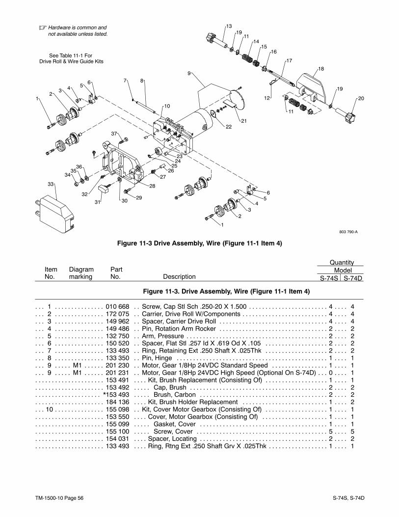
TM-1500-10 Page 56 S-74S, S-74D
See Table 11-1 For Drive Roll & Wire Guide Kits
� Hardware is common andnot available unless listed.
803 790-A
20
11
37
3635
34
33
32
31 30 29
28
2726
252423
1
23
45
6
2221
19
18
17
1615
14
1913
12
11
9
10
876543
21
Figure 11-3 Drive Assembly, Wire (Figure 11-1 Item 4)
ItemNo.
Diagrammarking
PartNo. Description
QuantityModel
S-74S S-74D
Figure 11-3. Drive Assembly, Wire (Figure 11-1 Item 4)
1 010 668 Screw, Cap Stl Sch .250-20 X 1.500 4 4. . . . . . . . . . . . . . . . . . . . . . . . . . . . . . . . . . . . . . . . . . . . . . . . 2 172 075 Carrier, Drive Roll W/Components 4 4. . . . . . . . . . . . . . . . . . . . . . . . . . . . . . . . . . . . . . . . . . . . . . . . . . 3 149 962 Spacer, Carrier Drive Roll 4 4. . . . . . . . . . . . . . . . . . . . . . . . . . . . . . . . . . . . . . . . . . . . . . . . . . . . . . . . . 4 149 486 Pin, Rotation Arm Rocker 2 2. . . . . . . . . . . . . . . . . . . . . . . . . . . . . . . . . . . . . . . . . . . . . . . . . . . . . . . . . 5 132 750 Arm, Pressure 2 2. . . . . . . . . . . . . . . . . . . . . . . . . . . . . . . . . . . . . . . . . . . . . . . . . . . . . . . . . . . . . . . . . . . 6 150 520 Spacer, Flat Stl .257 Id X .619 Od X .105 2 2. . . . . . . . . . . . . . . . . . . . . . . . . . . . . . . . . . . . . . . . . . . 7 133 493 Ring, Retaining Ext .250 Shaft X .025Thk 2 2. . . . . . . . . . . . . . . . . . . . . . . . . . . . . . . . . . . . . . . . . . . 8 133 350 Pin, Hinge 1 1. . . . . . . . . . . . . . . . . . . . . . . . . . . . . . . . . . . . . . . . . . . . . . . . . . . . . . . . . . . . . . . . . . . . . . 9 M1 201 230 Motor, Gear 1/8Hp 24VDC Standard Speed 1 1. . . . . . . . . . . . . . . . . . . . . . . . . . . . . . . . . . . . . 9 M1 201 231 Motor, Gear 1/8Hp 24VDC High Speed (Optional On S-74D) 0 1. . . . . . . . . . . . . . . . . . . . . . .
153 491 Kit, Brush Replacement (Consisting Of) 1 1. . . . . . . . . . . . . . . . . . . . . . . . . . . . . . . . . . . . . . . . . . . . . . . . 153 492 Cap, Brush 2 2. . . . . . . . . . . . . . . . . . . . . . . . . . . . . . . . . . . . . . . . . . . . . . . . . . . . . . . . . . . . . . . . . . . . . . . .
*153 493 Brush, Carbon 2 2. . . . . . . . . . . . . . . . . . . . . . . . . . . . . . . . . . . . . . . . . . . . . . . . . . . . . . . . . . . . . . . . . . . . 184 136 Kit, Brush Holder Replacement 1 2. . . . . . . . . . . . . . . . . . . . . . . . . . . . . . . . . . . . . . . . . . . . . . . . . . . . . . .
10 155 098 Kit, Cover Motor Gearbox (Consisting Of) 1 1. . . . . . . . . . . . . . . . . . . . . . . . . . . . . . . . . . . . . . . . . . . 153 550 Cover, Motor Gearbox (Consisting Of) 1 1. . . . . . . . . . . . . . . . . . . . . . . . . . . . . . . . . . . . . . . . . . . . . . . . . 155 099 Gasket, Cover 1 1. . . . . . . . . . . . . . . . . . . . . . . . . . . . . . . . . . . . . . . . . . . . . . . . . . . . . . . . . . . . . . . . . . . . . 155 100 Screw, Cover 5 5. . . . . . . . . . . . . . . . . . . . . . . . . . . . . . . . . . . . . . . . . . . . . . . . . . . . . . . . . . . . . . . . . . . . . . 154 031 Spacer, Locating 2 2. . . . . . . . . . . . . . . . . . . . . . . . . . . . . . . . . . . . . . . . . . . . . . . . . . . . . . . . . . . . . . . . . . . . 133 493 Ring, Rtng Ext .250 Shaft Grv X .025Thk 1 1. . . . . . . . . . . . . . . . . . . . . . . . . . . . . . . . . . . . . . . . . . . . . . .
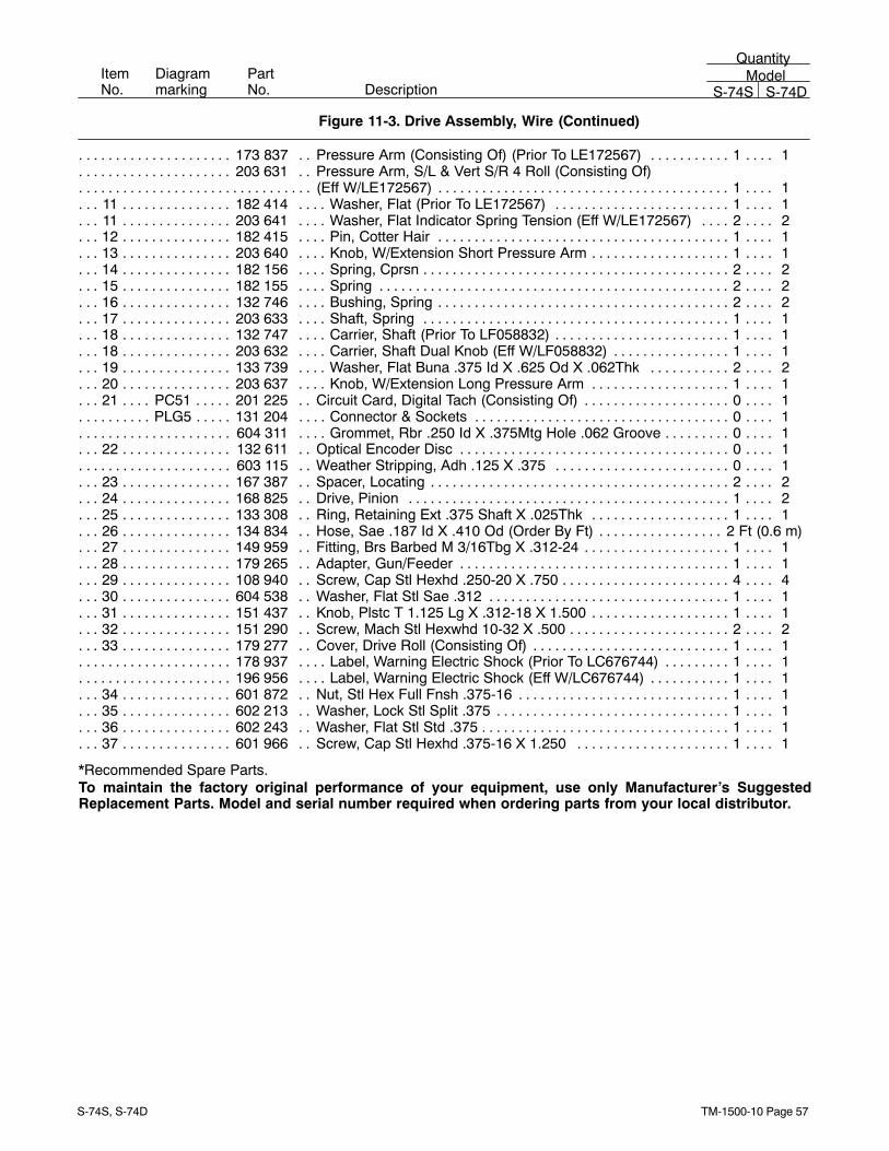
TM-1500-10 Page 57S-74S, S-74D
ItemNo.
Diagrammarking
PartNo. Description
QuantityModel
S-74S S-74D
Figure 11-3. Drive Assembly, Wire (Continued)
173 837 Pressure Arm (Consisting Of) (Prior To LE172567) 1 1. . . . . . . . . . . . . . . . . . . . . . . . . . . . . . . . . . . . . . 203 631 Pressure Arm, S/L & Vert S/R 4 Roll (Consisting Of) . . . . . . . . . . . . . . . . . . . . . . .
(Eff W/LE172567) 1 1. . . . . . . . . . . . . . . . . . . . . . . . . . . . . . . . . . . . . . . . . . . . . . . . . . . . . . . . . . . . . . . . . . . . . . . . . . . . 11 182 414 Washer, Flat (Prior To LE172567) 1 1. . . . . . . . . . . . . . . . . . . . . . . . . . . . . . . . . . . . . . . . . . . . . . . . . . 11 203 641 Washer, Flat Indicator Spring Tension (Eff W/LE172567) 2 2. . . . . . . . . . . . . . . . . . . . . . . . . . . . . . 12 182 415 Pin, Cotter Hair 1 1. . . . . . . . . . . . . . . . . . . . . . . . . . . . . . . . . . . . . . . . . . . . . . . . . . . . . . . . . . . . . . . . . . 13 203 640 Knob, W/Extension Short Pressure Arm 1 1. . . . . . . . . . . . . . . . . . . . . . . . . . . . . . . . . . . . . . . . . . . . . 14 182 156 Spring, Cprsn 2 2. . . . . . . . . . . . . . . . . . . . . . . . . . . . . . . . . . . . . . . . . . . . . . . . . . . . . . . . . . . . . . . . . . . . 15 182 155 Spring 2 2. . . . . . . . . . . . . . . . . . . . . . . . . . . . . . . . . . . . . . . . . . . . . . . . . . . . . . . . . . . . . . . . . . . . . . . . . . 16 132 746 Bushing, Spring 2 2. . . . . . . . . . . . . . . . . . . . . . . . . . . . . . . . . . . . . . . . . . . . . . . . . . . . . . . . . . . . . . . . . . 17 203 633 Shaft, Spring 1 1. . . . . . . . . . . . . . . . . . . . . . . . . . . . . . . . . . . . . . . . . . . . . . . . . . . . . . . . . . . . . . . . . . . . 18 132 747 Carrier, Shaft (Prior To LF058832) 1 1. . . . . . . . . . . . . . . . . . . . . . . . . . . . . . . . . . . . . . . . . . . . . . . . . . 18 203 632 Carrier, Shaft Dual Knob (Eff W/LF058832) 1 1. . . . . . . . . . . . . . . . . . . . . . . . . . . . . . . . . . . . . . . . . . 19 133 739 Washer, Flat Buna .375 Id X .625 Od X .062Thk 2 2. . . . . . . . . . . . . . . . . . . . . . . . . . . . . . . . . . . . . 20 203 637 Knob, W/Extension Long Pressure Arm 1 1. . . . . . . . . . . . . . . . . . . . . . . . . . . . . . . . . . . . . . . . . . . . . 21 PC51 201 225 Circuit Card, Digital Tach (Consisting Of) 0 1. . . . . . . . . . . . . . . . . . . . . . . . . . . . . . . . . . . . . .
PLG5 131 204 Connector & Sockets 0 1. . . . . . . . . . . . . . . . . . . . . . . . . . . . . . . . . . . . . . . . . . . . . . . . . . . . . . . . . . 604 311 Grommet, Rbr .250 Id X .375Mtg Hole .062 Groove 0 1. . . . . . . . . . . . . . . . . . . . . . . . . . . . . . . . . . . . . .
22 132 611 Optical Encoder Disc 0 1. . . . . . . . . . . . . . . . . . . . . . . . . . . . . . . . . . . . . . . . . . . . . . . . . . . . . . . . . . . . . 603 115 Weather Stripping, Adh .125 X .375 0 1. . . . . . . . . . . . . . . . . . . . . . . . . . . . . . . . . . . . . . . . . . . . . . . . . . .
23 167 387 Spacer, Locating 2 2. . . . . . . . . . . . . . . . . . . . . . . . . . . . . . . . . . . . . . . . . . . . . . . . . . . . . . . . . . . . . . . . . 24 168 825 Drive, Pinion 1 2. . . . . . . . . . . . . . . . . . . . . . . . . . . . . . . . . . . . . . . . . . . . . . . . . . . . . . . . . . . . . . . . . . . . 25 133 308 Ring, Retaining Ext .375 Shaft X .025Thk 1 1. . . . . . . . . . . . . . . . . . . . . . . . . . . . . . . . . . . . . . . . . . . 26 134 834 Hose, Sae .187 Id X .410 Od (Order By Ft) 2 Ft (0.6 m). . . . . . . . . . . . . . . . . . . . . . . . . . . . . . . . . . . . . 27 149 959 Fitting, Brs Barbed M 3/16Tbg X .312-24 1 1. . . . . . . . . . . . . . . . . . . . . . . . . . . . . . . . . . . . . . . . . . . . 28 179 265 Adapter, Gun/Feeder 1 1. . . . . . . . . . . . . . . . . . . . . . . . . . . . . . . . . . . . . . . . . . . . . . . . . . . . . . . . . . . . . 29 108 940 Screw, Cap Stl Hexhd .250-20 X .750 4 4. . . . . . . . . . . . . . . . . . . . . . . . . . . . . . . . . . . . . . . . . . . . . . . 30 604 538 Washer, Flat Stl Sae .312 1 1. . . . . . . . . . . . . . . . . . . . . . . . . . . . . . . . . . . . . . . . . . . . . . . . . . . . . . . . . 31 151 437 Knob, Plstc T 1.125 Lg X .312-18 X 1.500 1 1. . . . . . . . . . . . . . . . . . . . . . . . . . . . . . . . . . . . . . . . . . . 32 151 290 Screw, Mach Stl Hexwhd 10-32 X .500 2 2. . . . . . . . . . . . . . . . . . . . . . . . . . . . . . . . . . . . . . . . . . . . . . 33 179 277 Cover, Drive Roll (Consisting Of) 1 1. . . . . . . . . . . . . . . . . . . . . . . . . . . . . . . . . . . . . . . . . . . . . . . . . . .
178 937 Label, Warning Electric Shock (Prior To LC676744) 1 1. . . . . . . . . . . . . . . . . . . . . . . . . . . . . . . . . . . . . . 196 956 Label, Warning Electric Shock (Eff W/LC676744) 1 1. . . . . . . . . . . . . . . . . . . . . . . . . . . . . . . . . . . . . . . .
34 601 872 Nut, Stl Hex Full Fnsh .375-16 1 1. . . . . . . . . . . . . . . . . . . . . . . . . . . . . . . . . . . . . . . . . . . . . . . . . . . . . 35 602 213 Washer, Lock Stl Split .375 1 1. . . . . . . . . . . . . . . . . . . . . . . . . . . . . . . . . . . . . . . . . . . . . . . . . . . . . . . . 36 602 243 Washer, Flat Stl Std .375 1 1. . . . . . . . . . . . . . . . . . . . . . . . . . . . . . . . . . . . . . . . . . . . . . . . . . . . . . . . . . 37 601 966 Screw, Cap Stl Hexhd .375-16 X 1.250 1 1. . . . . . . . . . . . . . . . . . . . . . . . . . . . . . . . . . . . . . . . . . . . .
*Recommended Spare Parts.To maintain the factory original performance of your equipment, use only Manufacturer’s SuggestedReplacement Parts. Model and serial number required when ordering parts from your local distributor.
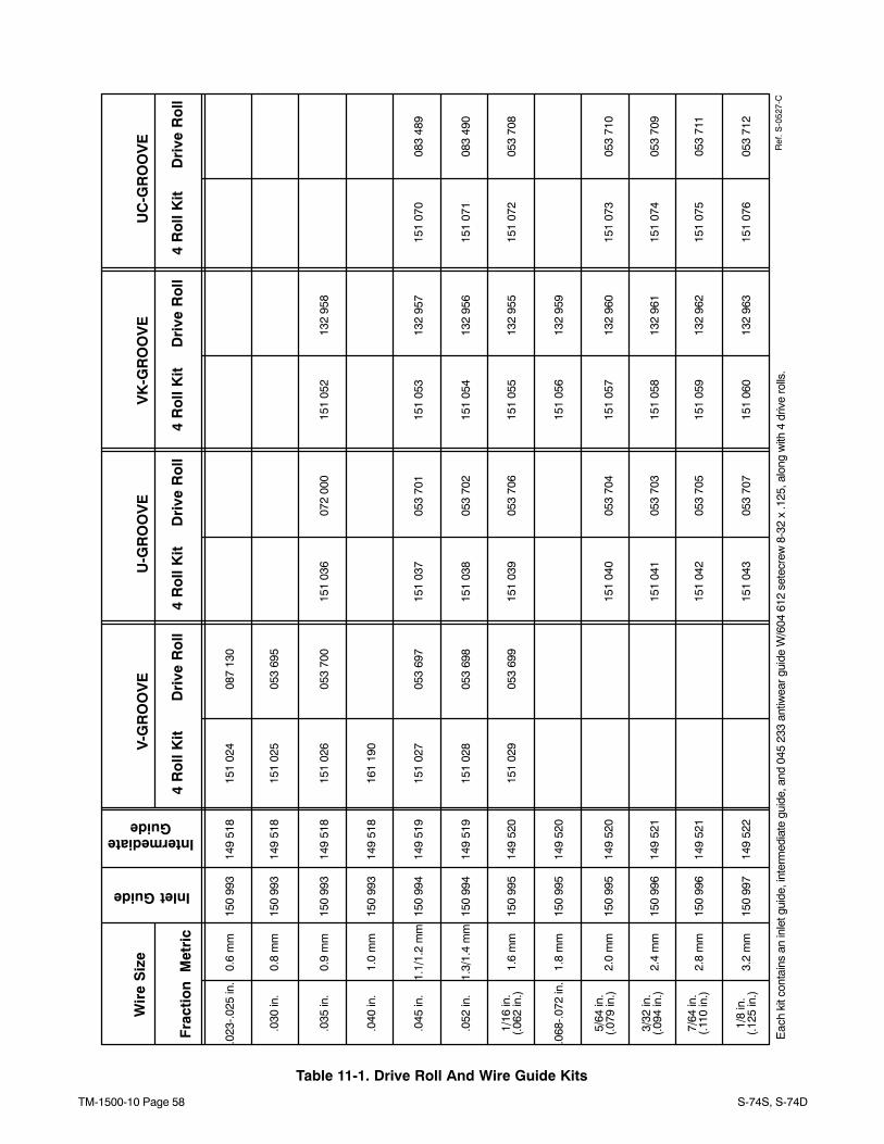
TM-1500-10 Page 58 S-74S, S-74D
UC
-GR
OO
VE
Table 11-1. Drive Roll And Wire Guide Kits
.023
-.02
5 in
.0.
6 m
m15
1 02
408
7 13
0
.030
in.
0.8
mm
151
025
053
695
.035
in.
0.9
mm
151
026
053
700
151
036
072
000
151
052
132
958
.045
in.
1.1/
1.2
mm
151
027
053
697
151
037
053
701
151
053
132
957
151
070
083
489
.052
in.
1.3/
1.4
mm
151
028
053
698
151
038
053
702
151
054
132
956
151
071
083
490
1/16
in.
1.6
mm
151
029
053
699
151
039
053
706
151
055
132
955
151
072
053
708
(.06
2 in
.)
.068
-.07
2 in
.1.
8 m
m15
1 05
613
2 95
9
5/64
in.
2.0
mm
151
040
053
704
151
057
132
960
151
073
053
710
(.07
9 in
.)
3/32
in.
(.09
4 in
.)2.
4 m
m15
1 04
105
3 70
315
1 05
813
2 96
115
1 07
405
3 70
9
7/64
in.
(.11
0 in
.)2.
8 m
m15
1 04
205
3 70
513
2 96
215
1 07
505
3 71
115
1 05
9
1/8
in.
(.12
5 in
.)3.
2 m
m15
1 04
305
3 70
715
1 06
013
2 96
315
1 07
605
3 71
2
150
993
150
993
150
993
150
994
150
994
150
995
150
995
150
995
150
996
150
996
150
997
149
518
149
518
149
518
149
519
149
519
149
520
149
520
149
520
149
521
149
521
149
522
.040
in.
1.0
mm
161
190
150
993
149
518
Ref
. S-0
527-
C
VK
-GR
OO
VE
U-G
RO
OV
EV
-GR
OO
VE
4 R
oll
Kit
Dri
ve R
oll
4 R
oll
Kit
Dri
ve R
oll
4 R
oll
Kit
Dri
ve R
oll
4 R
oll
Kit
Dri
ve R
oll
Wir
e S
ize
Fra
ctio
nM
etri
c
Inlet Guide
IntermediateGuide
Eac
h ki
t con
tain
s an
inle
t gui
de, i
nter
med
iate
gui
de, a
nd 0
45 2
33 a
ntiw
ear g
uide
W/6
04 6
12 s
etec
rew
8-3
2 x
.125
, alo
ng w
ith 4
driv
e ro
lls.
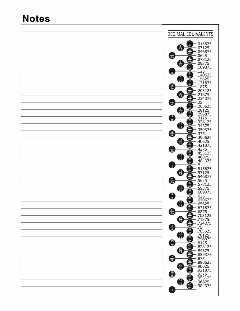
Notes

PRINTED IN USA © 2006 Miller Electric Mfg. Co.
Miller Electric Mfg. Co.An Illinois Tool Works Company1635 West Spencer StreetAppleton, WI 54914 USA
International Headquarters−USAUSA Phone: 920-735-4505 Auto-AttendedUSA & Canada FAX: 920-735-4134International FAX: 920-735-4125
European Headquarters −United KingdomPhone: 44 (0) 1204-593493FAX: 44 (0) 1204-598066