S-70-1 linear slot diffusers - mech-elec.netmech-elec.net/userfiles/File/Database/Series...
21
3 SERIES 70-1 Contents S-70-1 linear slot diffusers S-74-18, S-72-18 S-74-25, S-72-25, S-72-25FF Page. S-74-18 linear slot diffusers Description _________________________________________________ 4 Selection table ______________________________________________ 5 Selection in a sample project ___________________________________ 7 S-74-25 high-capacity linear slot diffusers Description _________________________________________________ 8 Selection table ______________________________________________ 9 Selection in a sample project ___________________________________ 11 S-72-25FF linear slot diffusers with filter holder Selection table ______________________________________________ 12 Induction rate S-74-18 and S-74-25 diffusers __________________________________ 13 General dimensions Linear slot diffuser models _____________________________________ 14 Types of plenums ____________________________________________ 15 Dimension tables for S-74-18 ___________________________________ 16 Dimension tables for S-74-25 ___________________________________ 19 Dimension tables for S-74-25FF _________________________________ 22 Useful Recommendations _____________________________________ 23 - The 70-1 SERIES linear diffusers are designed for constant flow. - For VARIABLE flow, KFD and KLD linear slot diffusers are available S-74-25-FF S-72-25-FF
Transcript of S-70-1 linear slot diffusers - mech-elec.netmech-elec.net/userfiles/File/Database/Series...

3SERIES 70-1
Contents
S-70-1 linear slot diffusersS-74-18, S-72-18S-74-25, S-72-25, S-72-25FF
Page.S-74-18 linear slot diffusersDescription _________________________________________________ 4Selection table ______________________________________________ 5Selection in a sample project ___________________________________ 7
S-74-25 high-capacity linear slot diffusersDescription _________________________________________________ 8Selection table ______________________________________________ 9Selection in a sample project ___________________________________ 11
S-72-25FF linear slot diffusers with filter holderSelection table ______________________________________________ 12
Induction rateS-74-18 and S-74-25 diffusers __________________________________ 13
General dimensionsLinear slot diffuser models _____________________________________ 14Types of plenums ____________________________________________ 15Dimension tables for S-74-18 ___________________________________ 16Dimension tables for S-74-25 ___________________________________ 19Dimension tables for S-74-25FF_________________________________ 22
Useful Recommendations _____________________________________ 23
- The 70-1 SERIES linear diffusers are designed for constant flow.
- For VARIABLE flow, KFD and KLD linear slot diffusers are available
S-74-25-FF S-72-25-FF

4 SERIES 70-1
S-74-18 linear slot diffusers
DescriptionS-74-18 linear slot diffuser for supply air. Aluminiumconstruction with standard natural anodized or stan-dard glossy RAL-9010 white pre-lacquered finish. Blackdeflections vanes with a matte finish. The S-74-18-Pmodel includes a inlet plenum made of galvanizedsteel sheet, with or without insulation. Threeattachment systems are available for the plenum:screws, bridges or clips. The systems are describedon pages 14 and 15.
ApplicationS-74-18 linear slot diffusers are speciallyrecommended for ceiling installation, with thedeflection vanes allowing air flow to be adjusted from0° to 180°. The diffusers are equipped with a slidingvolume control damper. For return air, it is possible touse the S-72-18 model (which has no volume controldamper). High-quality aesthetics and performance arefurther enhanced by alternating the return diffuserswith supply diffusers in the same continuous line. Todetermine the return flow, refer to the respectiveinstructions on page 23 (recommendations).
DimensionsThe "L" dimension (length) is always active lenght.The nominal or OPENING dimension is equal to L+25mm.The "G" dimension is the width of the OPENING andis listed in the dimension tables. See overalldimensions, including frames and end caps, on pages16 to 22.
IdentificationS-74-18 diffusers are equipped with deflection vanesand volume control dampers. Models without a plenuminclude the mounting bridges. For return air, it ispossible to use the S-72-18 model, which does notinclude the volume control damper but does includethe deflection vanes. All diffusers comes with end capsin the heads. In diffusers with plenum, one of the threesystems for attaching the plenum to the diffuser mustbe defined.
S-74-18-P
S-74-18 Linear slot diffuser, 18 mm, with regulation. S-72-18 Linear slot diffuser, 18 mm, without regulation.
PM Mounting bridge. CL Mounting clips.
1,2,3,4,5,6 Number of slots.
PF Fix plenum. PD Removable plenum. PC Plenum with clips.
PFA PDA Insulated plenum. PCA
S-74-18
S-74-18
G (OPENING)
ACTIVE LENGHT
OPENING=nominal
OVERALL DIMENSION

5SERIES 70-1
Selection table for S-74-18 (lateral discharge)
- This selection table is based on laboratory tests as per ISO5219 (UNE 100.710) and ISO 5135 and 3741.
- The ΔT is equal to -10ºC, the temperature difference betweenthe room and the supply air.
Symbols
Q (m3/h) = Air flow A
K(m2) = Effective area
Vk(m/s) = Effective supply velocity
X(m) = Throw of the air jet Pt(Pa) = Total pressure drop, in Pa dB(A) = Sound power level
Dim. 600-1 900-1 1200-1
600-2
1500-1 900-2
600-3
1200-2
600-4
900-3 1500-2 1200-3
900-4
1500-3 1200-4 1500-4
(m3/h) (l/s) Ak (m2) 0,00598 0,00897 0,01196 0,01495 0,01794 0,02391 0,02690 0,02989 0,03587 0,04484 0,04783 0,05978
60 16,7 Vk (m/s) 2,8 1,9 1,4 1,1X (m) 1,5 1,2 1,0 0,9Pt (Pa) 19 8 5 3dB(A) 27 <20 <20 <20
80 22,2 Vk (m/s) 3,7 2,5 1,9 1,5 1,2X (m) 2,0 1,6 1,4 1,2 1,1Pt (Pa) 35 14 9 6 5dB(A) 35 27 21 <20 <20
100 27,8 Vk (m/s) 4,6 3,1 2,3 1,9 1,5 1,2 1,0X (m) 2,4 2,0 1,7 1,5 1,4 1,2 1,2Pt (Pa) 54 21 14 9 8 5 4dB(A) 41 33 27 23 <20 <20 <20
140 38,9 Vk (m/s) 6,5 4,3 3,3 2,6 2,2 1,6 1,4 1,3 1,1X (m) 3,4 2,8 2,4 2,2 2,0 1,7 1,6 1,5 1,4Pt (Pa) 106 41 28 18 15 11 8 4 4dB(A) 51 42 37 32 29 23 21 <20 <20
180 50,0 Vk (m/s) 5,6 4,2 3,3 2,8 2,1 1,9 1,7 1,4 1,1 1,0X (m) 3,6 3,1 2,8 2,5 2,2 2,1 2,0 1,8 1,6 1,6Pt (Pa) 68 46 30 24 18 13 7 7 5 4dB(A) 49 44 39 36 30 27 25 24 <20 <20
200 55,6 Vk (m/s) 6,2 4,6 3,7 3,1 2,3 2,1 1,9 1,5 1,2 1,2X (m) 4,0 3,5 3,1 2,8 2,4 2,3 2,2 2,0 1,8 1,7Pt (Pa) 84 57 36 30 22 16 9 8 6 5dB(A) 52 47 42 38 33 30 28 27 22 21
250 69,4 Vk (m/s) 5,8 4,6 3,9 2,9 2,6 2,3 1,9 1,5 1,5 1,2X (m) 4,3 3,9 3,5 3,1 2,9 2,7 2,5 2,2 2,2 1,9Pt (Pa) 89 57 47 34 24 14 13 9 8 5dB(A) 53 48 45 39 37 34 33 28 27 23
300 83,3 Vk (m/s) 5,6 4,6 3,5 3,1 2,8 2,3 1,9 1,7 1,4X (m) 4,6 4,2 3,7 3,5 3,3 3,0 2,7 2,6 2,3Pt (Pa) 82 68 49 35 20 19 13 11 7dB(A) 53 50 44 42 40 38 33 32 28
400 111,1 Vk (m/s) 4,6 4,1 3,7 3,1 2,5 2,3 1,9X (m) 4,9 4,6 4,4 4,0 3,6 3,5 3,1Pt (Pa) 87 62 35 34 23 20 13dB(A) 52 50 47 46 41 40 36
500 138,9 Vk (m/s) 4,6 3,9 3,1 2,9 2,3X (m) 5,5 5,0 4,5 4,3 3,9Pt (Pa) 55 53 36 32 20dB(A) 54 52 48 46 42
600 166,7 Vk (m/s) 3,7 3,5 2,8X (m) 5,4 5,2 4,6Pt (Pa) 52 45 29dB(A) 53 51 47
700 194,4 Vk (m/s) 4,1 3,3X (m) 6,1 5,4Pt (Pa) 62 40dB(A) 56 51
800 222,2 Vk (m/s) 3,7X (m) 6,2Pt (Pa) 52dB(A) 55
QLONGITUD EN mm Y NÚMERO DE VÍASLENGHT in mm and NUMBER OF SLOTS

6 SERIES 70-1
- The air jet is adherent (Coanda effect), i.e., the diffuser ismounted flush with the ceiling.
For the selection tables with vertical discharge:
- The diffuser is positioned in the middle of the ceiling in asquare room.
- Positioning for vertical discharge, as non-adhering jet.
- The diffuser length is less than 0,5 times the width of theroom and less than 0,5 times the throw.
- The pressure Pt is measured in the duct upstream of the
plenum.
- The height of the room is 3 ± 0,5 m.
- The ΔT is equal to -10ºC, the temperature difference betweenthe room and the supply air.
- The maximum velocity is 0,25 m/s in the occupied zone.
Selection table for S-74-18 (vertical discharge)
Dim. 600-1 900-1 1200-1
600-2
1500-1 900-2 1200-2 1500-2
(m 3/h) (l/s) Ak (m2) 0,00622 0,00933 0,01243 0,01554 0,01865 0,02487 0,03109
60 16,7 Vk (m/s) 2,7 1,8X (m) 1,1 0,9Pt (Pa) 31 12dB(A) 20 <20
80 22,2 Vk (m/s) 3,6 2,4 1,8 1,4X (m) 1,5 1,2 1,0 0,9Pt (Pa) 54 21 14 9dB(A) 29 22 <20 <20
100 27,8 Vk (m/s) 4,5 3,0 2,2 1,8 1,5 1,1X (m) 1,8 1,5 1,3 1,2 1,1 0,9Pt (Pa) 85 33 21 14 10 6dB(A) 36 29 25 21 <20 <20
140 38,9 Vk (m/s) 6,3 4,2 3,1 2,5 2,1 1,6 1,3X (m) 2,6 2,1 1,8 1,6 1,5 1,3 1,1Pt (Pa) 166 65 42 27 20 12 7dB(A) 46 39 35 31 28 24 20
180 50,0 Vk (m/s) 5,4 4,0 3,2 2,7 2,0 1,6X (m) 2,7 2,3 2,1 1,9 1,6 1,5Pt (Pa) 108 69 44 32 20 11dB(A) 47 42 39 36 31 28
200 55,6 Vk (m/s) 6,0 4,5 3,6 3,0 2,2 1,8X (m) 3,0 2,6 2,3 2,1 1,8 1,6Pt (Pa) 133 85 54 40 24 14dB(A) 50 45 42 39 34 31
250 69,4 Vk (m/s) 5,6 4,5 3,7 2,8 2,2X (m) 3,2 2,9 2,6 2,3 2,0Pt (Pa) 133 85 62 38 21dB(A) 52 49 46 41 38
300 83,3 Vk (m/s) 5,4 4,5 3,4 2,7X (m) 3,5 3,2 2,7 2,4Pt (Pa) 122 90 54 31dB(A) 54 51 47 43
400 111,1 Vk (m/s) 4,5 3,6X (m) 3,7 3,2Pt (Pa) 97 54dB(A) 55 52
500 138,9 Vk (m/s) 4,5X (m) 4,0Pt (Pa) 85dB(A) 59
QLONGITUD EN mm Y NÚMERO DE VÍAS
NOTES ON SELECTION TABLES
For the selection tables with lateral discharge:
- The diffuser is positioned along the longitudinal axis of theceiling, next to the wall, in a room of the following size:
L=Length, A=Width and I=Length of the diffuser.
(A - I) / L = 0,5
Symbols
Q (m3/h) = Air flow A
K(m2) = Effective area
Vk(m/s) = Effective supply velocity
X(m) = Throw of the air jet P
t(Pa) = Total pressure drop, in Pa
dB(A) = Sound power level
LENGHT in mm and NUMBER OF SLOTS
7SERIES 70-1
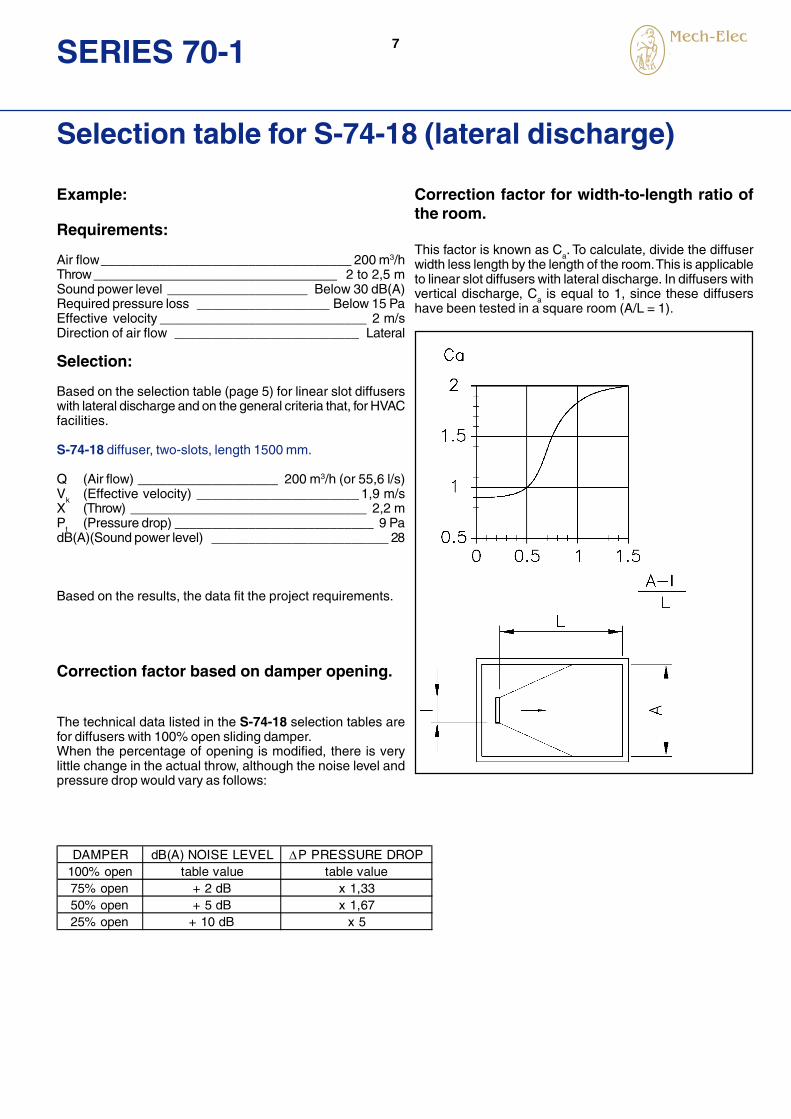
Example:
Requirements:
Air flow__________________________________ 200 m3/hThrow _________________________________ 2 to 2,5 mSound power level ___________________ Below 30 dB(A)Required pressure loss __________________ Below 15 PaEffective velocity ____________________________ 2 m/sDirection of air flow _________________________ Lateral
Selection:
Based on the selection table (page 5) for linear slot diffuserswith lateral discharge and on the general criteria that, for HVACfacilities.
S-74-18 diffuser, two-slots, length 1500 mm.
Q (Air flow) ___________________ 200 m3/h (or 55,6 l/s)V
k(Effective velocity) ______________________ 1,9 m/s
X (Throw) ________________________________ 2,2 mP
t(Pressure drop) ___________________________ 9 Pa
dB(A)(Sound power level) ________________________ 28
Based on the results, the data fit the project requirements.
Correction factor based on damper opening.
The technical data listed in the S-74-18 selection tables arefor diffusers with 100% open sliding damper.When the percentage of opening is modified, there is verylittle change in the actual throw, although the noise level andpressure drop would vary as follows:
Selection table for S-74-18 (lateral discharge)
Correction factor for width-to-length ratio ofthe room.
This factor is known as Ca. To calculate, divide the diffuser
width less length by the length of the room. This is applicableto linear slot diffusers with lateral discharge. In diffusers withvertical discharge, C
a is equal to 1, since these diffusers
have been tested in a square room (A/L = 1).
DAMPER dB(A) NOISE LEVEL P PRESSURE DROP100% open table value table value75% open + 2 dB x 1,3350% open + 5 dB x 1,6725% open + 10 dB x 5

8 SERIES 70-1
DescriptionS-74-25 high-capacity linear slot diffuser for supplyair. Aluminium construction in standard naturalanodized or standard glossy RAL-9010 white pre-enamelled finish. Black deflection vanes with a mattefinish. The S-74-25-P.. model includes a inlet plenummade of galvanized steel sheet, with or withoutinsulation. Three attachment systems are availablefor the plenum: screws, bridges or clips. The systemsand coding are described on pages 14 to 15.
ApplicationS-74-25 linear slot diffusers are speciallyrecommended for ceiling installation and allow 25%more air flow (for the same length) than the S-74-18model, with the deflection vanes allowing the air flowto be adjusted from 0° to 180°. These diffusers areequipped with a sliding volume control damper. High-quality aesthetics and performance are furtherenhanced by alternating the return diffusers with supplydiffusers in the same continuous line. For return air, itis possible to use the S-72-25 or S-72-25/18 models(which do not have a control damper) or the S-72-25FF hinged filter holder model. To determine the returnflow, refer to the respective instructions on page 23(recommendations).
DimensionsThe "L" dimension (length) is always active lenght.The nominal or OPENING dimension is equal to L+25mm. The "G" dimension is the width of the OPENINGand is listed in the dimension tables (see generaldimensions, including frames and end caps, on pages19 to 22).
IdentificationS-74-25 diffusers are equipped with deflection vanesand volume control damper. Models without a plenuminclude mounting bridges. For return air, it is possibleto use the S-72-25 or S-72-25/18 models, which donot include volume control dampers but do includethe deflection vanes, or the S-72-25FF filter holdermodel, hinged toward the outside for easy filterchanges. All diffusers comes with end caps in theheads. In diffusers with plenum, one of the threesystems for attaching the plenum to the diffuser mustbe defined (except S-72-25FF, which may only be PFor PD).
S-74-25 high-capacity linear slot diffusers
S-74-25-P
S-74-25
S-72-25FF hinged filter holder
S-74-25 Linear slot diffuser, 25 mm, adjustable. S-72-25 Linear slot diffuser, 25 mm, non-adjustable.S-72-25/18 Linear slot diffuser, 25 mm, 18-mm vane, without regulation.S-72-25FF Linear slot diffuser, 25 mm, hinged filter holder.
PM Mounting bridge. CL Mounting clips.PM
1,2,3,4,5,6 Number of slots.
PF Fix plenum. PD Removable plenum. PC Plenum with clips.
PFA PDA Insulated plenum. PCA

9SERIES 70-1
Selection table for S-74-25, high-capacity (lateraldischarge)
- The ΔT is equal to -10°C, the temperature difference betweenthe room and the supply air.
- The maximum velocity is 0,25 m/s in the occupied zone.
- This selection table is based on laboratory tests as perISO 5219 (UNE 100.710) and ISO 5135 and 3741.
Dim. 600-1 900-1 1200-1
600-2
1500-1 900-2
600-3
1200-2
600-4
900-3 1500-2 1200-3
900-4
1500-3 1200-4 1500-4
(m3/h) (l/s) Ak (m2) 0,00672 0,01007 0,01343 0,01679 0,02015 0,02687 0,03022 0,03358 0,04030 0,05037 0,05373 0,06716
60 16,7 Vk (m/s) 2,5 1,7 1,2 1,0X (m) 1,3 1,1 0,9 0,8Pt (Pa) 13 6 3 2dB(A) 27 <20 <20 <20
80 22,2 Vk (m/s) 3,3 2,2 1,7 1,3 1,1X (m) 1,7 1,4 1,2 1,1 1,0Pt (Pa) 23 10 6 4 3dB(A) 34 26 20 <20 <20
100 27,8 Vk (m/s) 4,1 2,8 2,1 1,7 1,4 1,0X (m) 2,2 1,8 1,5 1,4 1,3 1,1Pt (Pa) 37 16 9 6 4 2dB(A) 39 31 26 22 <20 <20
140 38,9 Vk (m/s) 5,8 3,9 2,9 2,3 1,9 1,4 1,3 1,2 1,0X (m) 3,0 2,5 2,1 1,9 1,8 1,5 1,4 1,4 1,2Pt (Pa) 72 32 18 11 8 4 4 3 2dB(A) 47 39 34 30 27 20 <20 <20 <20
180 50,0 Vk (m/s) 5,0 3,7 3,0 2,5 1,9 1,7 1,5 1,2 1,0X (m) 3,2 2,8 2,5 2,3 2,0 1,8 1,7 1,6 1,4Pt (Pa) 53 30 19 13 7 6 5 3 2dB(A) 45 40 36 33 27 24 22 <20 <20
200 55,6 Vk (m/s) 5,5 4,1 3,3 2,8 2,1 1,8 1,7 1,4 1,1 1,0X (m) 3,5 3,1 2,7 2,5 2,2 2,0 1,9 1,8 1,6 1,5Pt (Pa) 65 37 23 16 9 7 6 4 3 2dB(A) 48 43 39 35 29 26 24 20 <20 <20
250 69,4 Vk (m/s) 5,2 4,1 3,4 2,6 2,3 2,1 1,7 1,4 1,3 1,0X (m) 3,8 3,4 3,1 2,7 2,6 2,4 2,2 2,0 1,9 1,7Pt (Pa) 57 37 25 14 11 9 6 4 4 2dB(A) 48 44 41 34 32 29 25 21 <20 <20
300 83,3 Vk (m/s) 6,2 5,0 4,1 3,1 2,8 2,5 2,1 1,7 1,6 1,2X (m) 4,6 4,1 3,8 3,3 3,1 2,9 2,7 2,4 2,3 2,1Pt (Pa) 82 53 37 21 16 13 9 6 5 3dB(A) 52 48 45 39 36 34 30 26 23 <20
400 111,1 Vk (m/s) 6,6 5,5 4,1 3,7 3,3 2,8 2,2 2,1 1,7X (m) 5,5 5,0 4,3 4,1 3,9 3,5 3,2 3,1 2,7Pt (Pa) 94 65 37 29 23 16 10 9 6dB(A) 55 52 46 43 41 37 33 30 25
500 138,9 Vk (m/s) 5,2 4,6 4,1 3,4 2,8 2,6 2,1X (m) 5,4 5,1 4,8 4,4 4,0 3,8 3,4Pt (Pa) 57 45 37 25 16 14 9dB(A) 51 49 46 42 38 36 31
600 166,7 Vk (m/s) 5,5 5,0 4,1 3,3 3,1 2,5X (m) 6,1 5,8 5,3 4,7 4,6 4,1Pt (Pa) 65 53 37 23 21 13dB(A) 53 51 47 43 40 35
700 194,4 Vk (m/s) 5,8 4,8 3,9 3,6 2,9X (m) 6,8 6,2 5,5 5,4 4,8Pt (Pa) 72 50 32 28 18dB(A) 54 50 46 44 39
800 222,2 Vk (m/s) 5,5 4,4 4,1 3,3X (m) 7,1 6,3 6,1 5,5Pt (Pa) 65 42 37 23dB(A) 54 50 47 42
900 250,0 Vk (m/s) 5,0 4,7 3,7X (m) 7,1 6,9 6,2Pt (Pa) 53 46 30dB(A) 52 50 45
1000 277,8 Vk (m/s) 5,2 4,1X (m) 7,7 6,9Pt (Pa) 57 37dB(A) 53 48
1200 333,3 Vk (m/s) 5,0X (m) 8,2Pt (Pa) 53dB(A) 52
QLONGITUD EN mm Y NÚMERO DE VÍAS
Symbols
Q (m3/h) = Air flow A
K(m2) = Effective area
Vk(m/s) = Effective supply velocity
X(m) = Throw of the air jet Pt(Pa) = Total pressure drop, in Pa dB(A) = Sound power level
LENGHT in mm and NUMBER OF SLOTS
10 SERIES 70-1
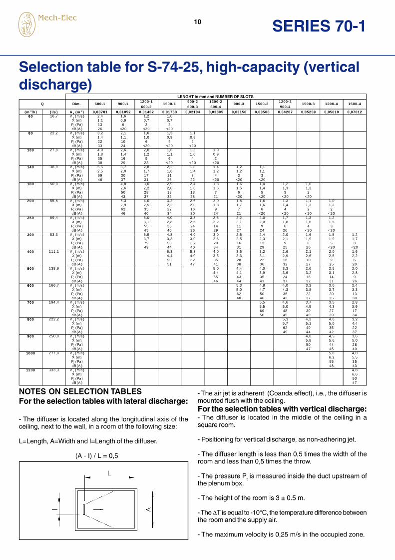
Selection table for S-74-25, high-capacity (verticaldischarge)
NOTES ON SELECTION TABLESFor the selection tables with lateral discharge:
- The diffuser is located along the longitudinal axis of theceiling, next to the wall, in a room of the following size:
L=Length, A=Width and I=Length of the diffuser.
(A - I) / L = 0,5
- The air jet is adherent (Coanda effect), i.e., the diffuser ismounted flush with the ceiling.For the selection tables with vertical discharge:- The diffuser is located in the middle of the ceiling in asquare room.
- Positioning for vertical discharge, as non-adhering jet.
- The diffuser length is less than 0,5 times the width of theroom and less than 0,5 times the throw.
- The pressure Pt is measured inside the duct upstream of
the plenum box.
- The height of the room is 3 ± 0.5 m.
- The ΔT is equal to -10°C, the temperature difference betweenthe room and the supply air.
- The maximum velocity is 0,25 m/s in the occupied zone.
Dim . 600-1 900-11200-1
600-21500-1
900-2
600-3
1200-2
600-4900-3 1500-2
1200-3
900-41500-3 1200-4 1500-4
(m 3/h ) ( l/s ) A k (m 2) 0,00701 0,01052 0,01402 0,01753 0,02104 0,02805 0,03156 0,03506 0,04207 0,05259 0,05610 0,0701260 16,7 V k (m/s ) 2,4 1,6 1,2 1,0
X (m) 1,1 0,9 0,7 0,7Pt (Pa) 13 6 3 2dB(A ) 26 <20 <20 <20
80 22,2 V k (m/s ) 3,2 2,1 1,6 1,3 1,1X (m) 1,4 1,1 1,0 0,9 0,8Pt (Pa) 22 10 6 4 2dB(A ) 33 24 <20 <20 <20
100 27,8 V k (m/s ) 4,0 2,6 2,0 1,6 1,3 1,0X (m) 1,8 1,4 1,2 1,1 1,0 0,9Pt (Pa) 35 16 9 6 4 2dB(A ) 38 29 23 <20 <20 <20
140 38,9 V k (m/s ) 5,5 3,7 2,8 2,2 1,8 1,4 1,2 1,1X (m) 2,5 2,0 1,7 1,6 1,4 1,2 1,2 1,1Pt (Pa) 69 30 17 11 8 4 3 3dB(A ) 46 37 31 26 22 <20 <20 <20
180 50,0 V k (m/s ) 4,8 3,6 2,9 2,4 1,8 1,6 1,4 1,2 1,0X (m) 2,6 2,2 2,0 1,8 1,6 1,5 1,4 1,3 1,2Pt (Pa) 50 28 18 13 7 6 5 3 2dB(A ) 43 37 32 28 21 <20 <20 <20 <20
200 55,6 Vk (m/s ) 5,3 4,0 3,2 2,6 2,0 1,8 1,6 1,3 1,1 1,0
X (m) 2,9 2,5 2,2 2,0 1,8 1,7 1,6 1,4 1,3 1,2P
t (Pa) 62 35 22 16 9 7 6 4 2 2
dB(A ) 46 40 34 30 24 21 <20 <20 <20 <20250 69,4 V
k (m/s ) 5,0 4,0 3,3 2,5 2,2 2,0 1,7 1,3 1,2
X (m) 3,1 2,8 2,5 2,2 2,1 2,0 1,8 1,6 1,5P
t (Pa) 55 35 24 14 11 9 6 4 3
dB(A ) 45 40 36 29 27 24 20 <20 <20300 83,3 V
k (m/s ) 5,9 4,8 4,0 3,0 2,6 2,4 2,0 1,6 1,5 1,2
X (m) 3,7 3,3 3,0 2,6 2,5 2,3 2,1 1,9 1,9 1,7P
t (Pa) 79 50 35 20 16 13 9 6 5 3
dB(A ) 49 44 40 34 31 29 25 20 <20 <20400 111,1 V
k (m/s ) 6,3 5,3 4,0 3,5 3,2 2,6 2,1 2,0 1,6
X (m) 4,4 4,0 3,5 3,3 3,1 2,9 2,6 2,5 2,2P
t (Pa) 90 62 35 28 22 16 10 9 6
dB(A ) 51 47 41 38 36 32 27 25 20500 138,9 V
k (m/s ) 5,0 4,4 4,0 3,3 2,6 2,5 2,0
X (m) 4,4 4,1 3,9 3,6 3,2 3,1 2,8P
t (Pa) 55 43 35 24 16 14 9
dB(A ) 46 44 41 37 32 31 26600 166,7 V
k (m/s ) 5,3 4,8 4,0 3,2 3,0 2,4
X (m) 5,0 4,7 4,3 3,8 3,7 3,3P
t (Pa) 62 50 35 22 20 13
dB(A ) 48 46 42 37 35 30700 194,4 V
k (m/s ) 5,5 4,6 3,7 3,5 2,8
X (m) 5,5 5,0 4,5 4,3 3,9P
t (Pa) 69 48 30 27 17
dB(A ) 50 45 40 39 34800 222,2 V
k (m/s ) 5,3 4,2 4,0 3,2
X (m) 5,7 5,1 5,0 4,4P
t (Pa) 62 40 35 22
dB(A ) 49 44 42 37900 250,0 V
k (m/s ) 4,8 4,5 3,6
X (m) 5,8 5,6 5,0Pt (Pa) 50 44 28dB(A ) 47 45 40
1000 277,8 V k (m/s ) 5,0 4,0X (m) 6,2 5,5Pt (Pa) 55 35dB(A ) 48 43
1200 333,3 V k (m/s ) 4,8X (m) 6,6Pt (Pa) 50dB(A ) 47
Q
LONGITUD EN m m Y NÚM ERO DE V ÍASLENGHT in mm and NUMBER OF SLOTS

11SERIES 70-1
Example
Requirements
Air flow__________________________________ 600 m3/hThrow ______________________________________ 4 mSound power level ___________________ Below 40 dB(A)Required pressure loss __________________ Below 15 PaEffective velocity _______________________ 2,5 to 3 m/sDirection of air flow _________________________ Lateral
Selection:
Based on the selection table (page 9) for linear slot diffuserswith lateral discharge and on the general criteria that, for HVACfacilities.
S-74-25 diffuser, four-slots, length 1600 mm
Q (Air flow) __________________ 600 m3/h (or 166,7 l/s)V
k(Effective velocity) ______________________ 2,5 m/s
X (Throw) ________________________________ 4,1 mPt (Pressure drop) __________________________ 13 PadB(A)(Sound power level) ________________________ 35
Based on the results, the data fit the project requirements
Correction factor based on damper opening
The technical data listed in the selection tables for the S-74-25 diffusers are for diffusers with 100% open sliding damper.When the percentage of opening is modified, there is verylittle change in the actual throw, although the noise level andpressure drop would vary as follows:
Selection example S-74-25, high-capacity (lateraldischarge)
Correction factor for width-to-length ratio ofthe room.This factor is known as Ca. To calculate, divide the diffuserwidth less length by the length of the room. This is applicableto linear slot diffusers with lateral discharge. In diffusers withvertical discharge, C
a is equal to 1, since these diffusers
have been tested in a square room (A/L = 1).
DAMPER dB(A) NOISE LEVEL P PRESSURE DROP100% open table value table value75% open + 2 dB x 1,3350% open + 5 dB x 1,6725% open + 10 dB x 5

12 SERIES 70-1
Selection table for S-72-25FF, for return (filterholder)
NOTE: The pressure drop (Pa) includes a Class G-2 filter.
(m3/h) (l/s)
80 22,2 dB(A) <20
Pst (Pa) 4
100 27,8 dB(A) <20 <20
Pst (Pa) 6 3
160 44,4 dB(A) 24 20 <20
Pst (Pa) 15 8 7
200 55,6 dB(A) 29 25 23 22 <20
Pst (Pa) 23 13 10 8 6
300 83,3 dB(A) 38 33 32 30 22 20 <20
Pst (Pa) 52 29 23 19 13 8 7
400 111,1 dB(A) 44 40 38 36 28 26 23 21
Pst (Pa) 93 52 41 33 23 15 13 8
500 138,9 dB(A) 49 44 43 41 33 31 28 26 23
Pst (Pa) 145 82 65 52 36 23 20 13 8
600 166,7 dB(A) 48 46 45 36 34 32 30 27
Pst (Pa) 118 93 75 52 33 29 19 12
700 194,4 dB(A) 50 48 40 38 35 33 30
Pst (Pa) 126 103 71 46 40 26 16
800 222,2 dB(A) 43 41 38 36 33
Pst (Pa) 93 60 52 33 21
900 250,0 dB(A) 45 43 40 38 35
Pst (Pa) 118 75 66 42 27
1000 277,8 dB(A) 45 42 41 38
Pst (Pa) 93 82 52 33
1200 333,3 dB(A) 49 46 44 41
Pst (Pa) 134 118 75 48
1400 388,9 dB(A) 48 45
Pst (Pa) 103 66
1600 444,4 dB(A) 51 48
Pst (Pa) 134 86
1800 500,0 dB(A) 50
Pst (Pa) 108
2000 555,6 dB(A) 52
Pst (Pa) 134
1200-41200-5
1500-41500-5
LONGITUD EN mm. Y NUMERO DE VIAS
900-5
1500-3900-3 600-5
Q 900-4
1200-3Dim. 600-3 600-4
This selection table is based on laboratory tests according to ISO 5219(UNE 100.710), ISO 5135 and ISO 3741 standards.
LENGHT in mm and NUMBER OF SLOTS

13SERIES 70-1
Induction rate
S-74-18 S-74-25
S-74-18 S-74-25
Induction effectThe induced air flow in the room can be determined usingthe factor (q
x/q
o) with the parameters X
c in m (corrected throw)
for lateral discharge diffusers, Y (throw in m) for verticaldischarge diffusers, and the effective area in m2 (A
k).
1
10
100
1 10
Xc (m)
qx/qo
0,0050,01
0,02
0,040,06
AK (m2 )
2 3 4 5
2
4
20
30
40
6
INDUCTION air flow in the jet for horizontal discharge
1
10
100
1 10
Xc (m)
qx/qo 0,005 0,01
0,02
0,040,06
AK (m2 )
2 3 4 5
2
4
20
30
40
6
INDUCTION air flow in the jet for vertical discharge
1
10
100
1 10
Xc (m)
qx/qo
0,005
0,010,02
0,040,06
AK (m2 )
2 3 4 5
2
4
20
3040
6
INDUCTION air flow in the jet for horizontal discharge
1
10
100
1 10
Xc (m)
qx/qo 0,005 0,01
0,02
0,040,06
AK (m2 )
2 3 4 5
2
4
20
3040
6
INDUCTION air flow in the jet for vertical discharge

14 SERIES 70-1
VS-70-1 linear slot diffuser models
Types of linear slot diffusersThis page presents a schematic description of the linear slot diffusers, including an overview of the different versions andplenum attachment systems, as well as the filter holder model.
Diffusers screwed toplenum
Diffusers withmounting bridge
Diffusers withmounting clips
S-74-25-PF S-74-25-PM S-74-25-CL
S-72-18-PF S-72-18-PM S-72-18-CL
S-72-25-PF S-72-25-PM S-72-25-CL
S-72-25FFfilter holder for return air (filter ≤ 5 mm)
S-74-18-PF S-74-18-PM S-74-18-CL
S-72-25/18-PF S-72-25/18-PM S-72-25/18-PC
15SERIES 70-1
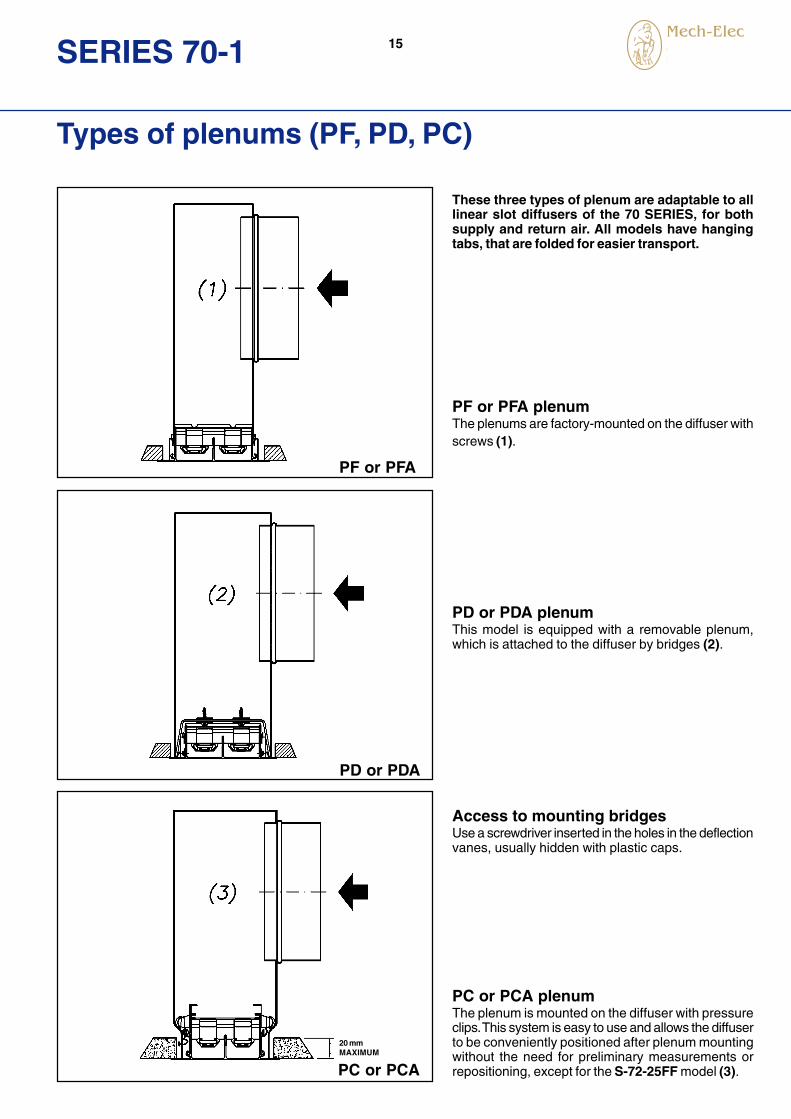
Types of plenums (PF, PD, PC)
These three types of plenum are adaptable to alllinear slot diffusers of the 70 SERIES, for bothsupply and return air. All models have hangingtabs, that are folded for easier transport.
PF or PFA plenumThe plenums are factory-mounted on the diffuser withscrews (1).
PD or PDA plenumThis model is equipped with a removable plenum,which is attached to the diffuser by bridges (2).
Access to mounting bridgesUse a screwdriver inserted in the holes in the deflectionvanes, usually hidden with plastic caps.
PC or PCA plenumThe plenum is mounted on the diffuser with pressureclips. This system is easy to use and allows the diffuserto be conveniently positioned after plenum mountingwithout the need for preliminary measurements orrepositioning, except for the S-72-25FF model (3).
PF or PFA
PD or PDA
PC or PCA
20 mmMAXIMUM

16 SERIES 70-1
General dimensions of S-74-PF
S-74-PF (fix plenum) or PFA (insulated fix plenum) linear slot diffusers
Note: The S-72-18 diffusers without volume control damperhave these same dimensions.
S-74-PF or PFA linear slot diffusers
ACTIVE LENGHT
(OPENING)(OPENING)
NOMINAL L E SLOTS A B ØD F G H
600 575 572 1 75 40 124 66 225
900 875 872 2 111 76 159 102 275
1200 1175 1172 3 147 112 199 138 325
1500 1475 1472 4 183 148 199 174 325
1800 1775 1772 5 219 184 249 210 375
2000 1975 1972 6 255 220 249 246 375
2025 2000 1997
DIMENSIONS S-74-18-PF (mm)
18
NOMINAL L E SLOTS A B ØD F G H
600 575 572 1 82 47 124 73 225
900 875 872 2 125 90 159 116 275
1200 1175 1172 3 168 133 199 159 325
1500 1475 1472 4 211 176 199 202 325
1800 1775 1772 5 254 219 249 245 375
2000 1975 1972 6 297 262 249 288 375
2025 2000 1997
DIMENSIONS S-74-25-PF (mm)
25
-NUMBER OF SPIGOTS:ACTIVE LENGHT > 1174 mm: 2 SPIGOTS
-NUMBER OF SPIGOTS:FROM 1 TO 4 SLOTS AND ACTIVE LENGHT > 1475 mm: 2 SPIGOTSFROM 5 TO 6 SLOTS AND ACTIVE LENGHT > 1174 mm: 2 SPIGOTS

17SERIES 70-1
General dimensions of S-74-PD
S-74-PD (removable plenum) or PDA (insulated removable plenum) linear slot diffusers
S-74-PD or PDA linear slot diffusers
Note: The S-72-18 diffusers without volume control damperhave these same dimensions.
ACTIVE LENGHT
(OPENING)(OPENING)
NOMINAL L E SLOTS A B ØD F G H
600 575 589 1 75 63 124 66 225
900 875 889 2 111 99 159 102 275
1200 1175 1189 3 147 135 199 138 325
1500 1475 1489 4 183 171 199 174 325
1800 1775 1789 5 219 207 249 210 375
2000 1975 1989 6 255 243 249 246 375
2025 2000 2014
DIMENSIONS S-74-18-PD (mm)
18
NOMINAL L E SLOTS A B ØD F G H
600 575 589 1 82 70 124 73 225
900 875 889 2 125 113 159 116 275
1200 1175 1189 3 168 156 199 159 325
1500 1475 1489 4 211 199 199 202 325
1800 1775 1789 5 254 242 249 245 375
2000 1975 1989 6 297 285 249 288 375
2025 2000 2014
DIMENSIONS S-74-25-PD (mm)
25
-NUMBER OF SPIGOTS:FROM 1 TO 4 SLOTS AND ACTIVE LENGHT > 1475 mm: 2 SPIGOTSFROM 5 TO 6 SLOTS AND ACTIVE LENGHT > 1174 mm: 2 SPIGOTS
-NUMBER OF SPIGOTS:ACTIVE LENGHT > 1174 mm: 2 SPIGOTS

18 SERIES 70-1
General dimensions of S-74-PC
S-74-PC (plenum with clips) or PCA (insulated plenum, with clips) linear slot diffusers
S-74-PC or PCA linear slot diffusers
Note: The S-72-18 diffusers without volume control damperhave these same dimensions.
(OPENING)(OPENING)
FILTER & SUPPORT(UPON REQUEST)
MAXIMUM
FILTER LENGHT
ACTIVE LENGHT
NOMINAL L E SLOTS A B C ØD F G H
600 575 589 1 75 76 54 124 66 225
900 875 889 2 111 112 90 159 102 275
1200 1175 1189 3 147 148 126 199 138 325
1500 1475 1489 4 183 184 162 199 174 325
1800 1775 1789 5 219 220 198 249 210 375
2000 1975 1989 6 255 256 234 249 246 375
2025 2000 2014
DIMENSIONS S-74-18-PC (mm)
18
NOMINAL L E SLOTS A B C ØD F G H
600 575 589 1 82 83 61 124 73 225
900 875 889 2 125 126 106 159 116 275
1200 1175 1189 3 168 169 147 199 159 325
1500 1475 1489 4 211 212 190 199 202 325
1800 1775 1789 5 254 255 233 249 245 375
2000 1975 1989 6 297 298 276 249 288 375
2025 2000 2014
25
DIMENSIONS S-74-25-PC (mm)
-NUMBER OF SPIGOTS:FROM 1 TO 4 SLOTS AND ACTIVE LENGHT > 1475 mm: 2 SPIGOTSFROM 5 TO 6 SLOTS AND ACTIVE LENGHT > 1174 mm: 2 SPIGOTS
-NUMBER OF SPIGOTS:ACTIVE LENGHT > 1174 mm: 2 SPIGOTS

19SERIES 70-1
Dimensions of S-72-25FF-PF
S-72-25FF-PF (fix plenum) linear slot diffusers with hinged filter holder
S-72-25FF-PF (Fix plenum) linear slot diffusers
ACTIVE LENGHT
(OPENING)18 mm
NOMINAL L E SLOTS A B ØD G H
600 575 572 3 168 133 199 159 325
900 875 872 4 211 176 199 202 325
1200 1175 1172 5 254 219 249 245 375
1500 1475 1472 6 297 262 249 288 375
1800 1775 1772
2000 1975 1972
2025 2000 1997
DIMENSIONS S-72-25-FF-PF (mm)

20 SERIES 70-1
Dimensions of S-72-25FF-PD
S-72-25FF-PD (Removable plenum) linear slot diffusers with hinged filter holder
S-72-25FF-PD (Removable plenum) linear slot diffusers
NOMINAL L E SLOTS A B ØD G H
600 575 589 3 168 156 199 159 325
900 875 889 4 211 199 199 202 325
1200 1175 1189 5 254 242 249 245 375
1500 1475 1489 6 297 285 249 288 375
1800 1775 1789
2000 1975 1989
2025 2000 2014
DIMENSIONS S-72-25-FF-PD (mm)
ACTIVE LENGHT
(OPENING)
FILTER
18 mm

21SERIES 70-1
Minimum recommended velocity in occupiedarea Vz.The temperature difference between cold supply air and theroom air, provides the following V
z values, as the
recommended velocity for the occupied zone to prevent theair jet falls to close, for lateral discharge diffusers:
Air flow measurementDiffusers with lateral dischargeThe air flow rate q
v is obtained from the product of the
effective area of the diffuser (Ak) in m2 and the velocity at
the discharge (Vk), measured with a TSI-VELOCICALC hot
wire anemometer located in the outer side frame.
Recommendations
Diffusers with vertical dischargeThe air flow rate q
v is obtained from the product of the
effective area of the diffuser (Ak) in m2 and the velocity at
the discharge (Vk), measured with a TSI-VELOCICALC hot
wire anemometer located in the discharge path.
Diffusers with length above 2000 mmDiffusers with a length above 2000 mm are supplied inseparate sections that are assembled with union pieces forperfect alignment, with end caps in the head sections at theend.
Application of S-70-1 diffusers for return orexhaust
For aesthetic reasons, the same components are usuallyinstalled for both air supply and return or exhaust. When alinear slot diffuser is used for exhaust, the effective cross-section for active lenght (A
k) is reduced by about 25%, with
respect to the same type of diffuser used for supply.
Since the pressure drop of the air and the sound power levelare directly related to the velocity and the effective area,this should be taken into consideration when selecting a li-near slot diffuser for return, decreasing the flow by the samepercentage with respect to the model selected for supply air.
In S-74-25 diffusers with a 25-mm slot, this cross-sectionalloss can be offset by using the deflection vanes from themodel with a 18-mm slot (S-74-18) to eliminate the abovedisadvantages. This diffuser is the S-72-25/18 model.
CONNECTION STRIPS
DETAILED VIEW OF CONNECTION TOCREATE LINES
0 6 9 12
0,15 0,25 0,30 0,35
0,15 0,20 0,25 0,30
Dt Cold supply air (°C)Vz (Minimum recommended velocity, in m/s)
Diffuser near exterior wallDiffuser near interior wall

22 SERIES 70-1

23SERIES 70-1


![Ceiling Slot Diffusers - Holyoakeattachments.holyoake.com/products/files/CJD[1193].pdf · Ceiling Slot Diffusers Dimensional Data – Series CSD 27B Notes 1. The illustration below](https://static.fdocuments.net/doc/165x107/5a9ff7737f8b9a76178d7320/ceiling-slot-diffusers-1193pdfceiling-slot-diffusers-dimensional-data-series.jpg)


![Linear Slot Diffusers - JPR SERVICESJPR].pdf · Selection Procedure Linear Slot Diffusers ... throw slot diffuser is required to deliver a total volume of 600 L/sec with a maximum](https://static.fdocuments.net/doc/165x107/5a9ff62d7f8b9a0d158d852a/linear-slot-diffusers-jpr-jprpdfselection-procedure-linear-slot-diffusers-.jpg)