RZ 200 Parts Diagram - Router Technologies
9
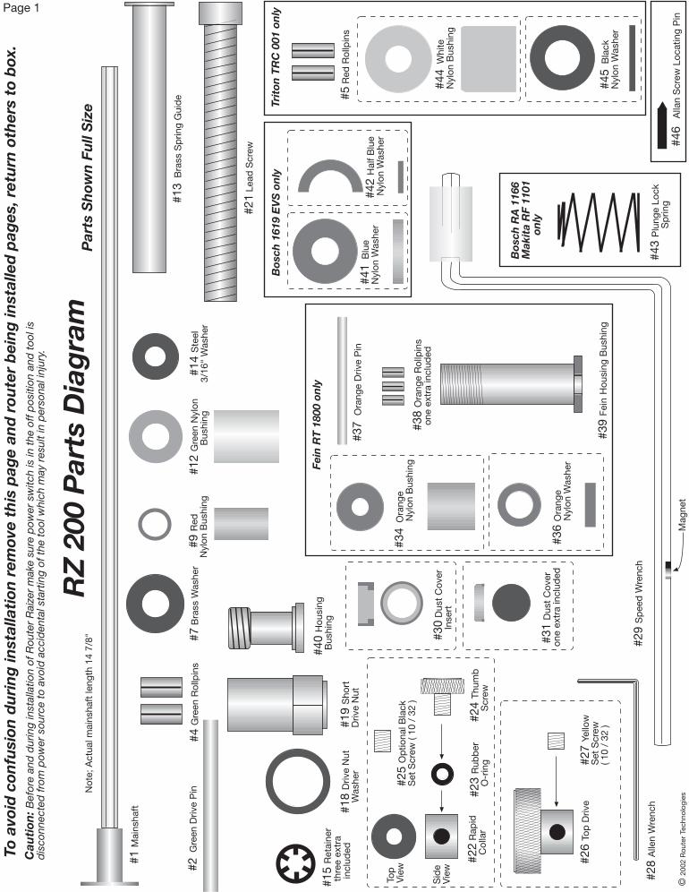
RZ 200 Parts Diagram Caution: Before and during installation of Router Raizer make sure power switch is in the off position and tool is disconnected from power source to avoid accidental starting of the tool which may result in personal injury. #13 Brass Spring Guide #15 Retainer three extra included #30 Dust Cover Insert #19 Short Drive Nut #40 Housing Bushing #18 Drive Nut Washer #37 Orange Drive Pin Parts Shown Full Size Page 1 Note; Actual mainshaft length 14 7/8" Top View Side View © 2002 Router Technologies #4 Green Rollpins #43 Plunge Lock Spring Bosch RA 1166 Makita RF 1101 only To avoid confusion during installation remove this page and router being installed pages, return others to box. Magnet Fein RT 1800 only Bosch 1619 EVS only #25 Optional Black Set Screw ( 10 / 32 ) Triton TRC 001 only #1 Mainshaft #29 Speed Wrench #21 Lead Screw #28 Allen Wrench #9 Red Nylon Bushing #41 Blue Nylon Washer #42 Half Blue Nylon Washer #39 Fein Housing Bushing #34 Orange Nylon Bushing #36 Orange Nylon Washer #22 Rapid Collar #23 Rubber O-ring #24 Thumb Screw #26 Top Drive #27 Yellow Set Screw ( 10 / 32 ) #38 Orange Rollpins one extra included #31 Dust Cover one extra included #2 Green Drive Pin #7 Brass Washer #12 Green Nylon Bushing #14 Steel 3/16" Washer #5 Red Rollpins #44 White Nylon Bushing #45 Black Nylon Washer #46 Allan Screw Locating Pin
Transcript of RZ 200 Parts Diagram - Router Technologies
RZ
200
Par
ts D
iag
ram
Cau
tion
: Bef
ore
and
dur
ing
inst
alla
tion
of R
oute
r R
aize
r m
ake
sure
pow
er s
witc
h is
in t
he o
ff p
ositi
on a
nd t
ool i
sd
isco
nnec
ted
from
pow
er s
ourc
e to
avo
id a
ccid
enta
l sta
rtin
g of
the
too
l whi
ch m
ay r
esul
t in
per
sona
l inj
ury.
#13
Bra
ss S
prin
g G
uid
e
#15
Ret
aine
r t
hree
ext
ra
incl
uded
#30
Dus
t C
over
In
sert
#19
Sho
rtD
rive
Nut
#40
Hou
sing
Bus
hing
#18
Driv
e N
ut
Was
her
#37
Ora
nge
Driv
e P
in
Par
ts S
how
n F
ull
Siz
e
Page 1
Not
e; A
ctua
l mai
nsha
ft le
ngth
14
7/8"
Top
Vie
w
Sid
eV
iew
© 2
002
Rou
ter
Tech
nolo
gies
#4 G
reen
Rol
lpin
s
#43
Plu
nge
Lock
Sp
ring
Bos
ch R
A 1
166
Mak
ita
RF
1101
on
ly
To a
void
con
fusi
on d
uri
ng
inst
alla
tion
rem
ove
this
pag
e an
d r
oute
r b
ein
g in
stal
led
pag
es, r
etu
rn o
ther
s to
box
.
Mag
net
Fein
RT
180
0 on
ly
Bos
ch 1
619
EV
S o
nly
#25
Op
tiona
l Bla
ckS
et S
crew
( 10
/ 3
2 )
Trit
on T
RC
001
on
ly
#1 M
ains
haft
#29
Sp
eed
Wre
nch
#21
Lead
Scr
ew
#28
Alle
n W
renc
h
#9
Red
Nyl
on B
ushi
ng
#41
Blu
eN
ylon
Was
her
#42
Hal
f Blu
e N
ylon
Was
her
#39
Fei
n H
ousi
ng B
ushi
ng
#34
Ora
nge
N
ylon
Bus
hing
#36
Ora
nge
N
ylon
Was
her
#22
Rap
id
Col
lar
#23
Rub
ber
O
-rin
g#2
4 Th
umb
S
crew
#26
Top
Driv
e#2
7 Ye
llow
Set
Scr
ew( 1
0 /
32 )
#38
Ora
nge
Rol
lpin
s o
ne e
xtra
incl
uded
#31
Dus
t C
over
one
extr
a in
clud
ed
#2 G
reen
Driv
e P
in#7
Bra
ss W
ashe
r#1
2 G
reen
Nyl
on
Bus
hing
#14
Ste
el3/
16"
Was
her
#5 R
ed R
ollp
ins
#44
Whi
teN
ylon
Bus
hing
#45
Bla
ckN
ylon
Was
her
#46
Alla
n S
crew
Loc
atin
g P
in
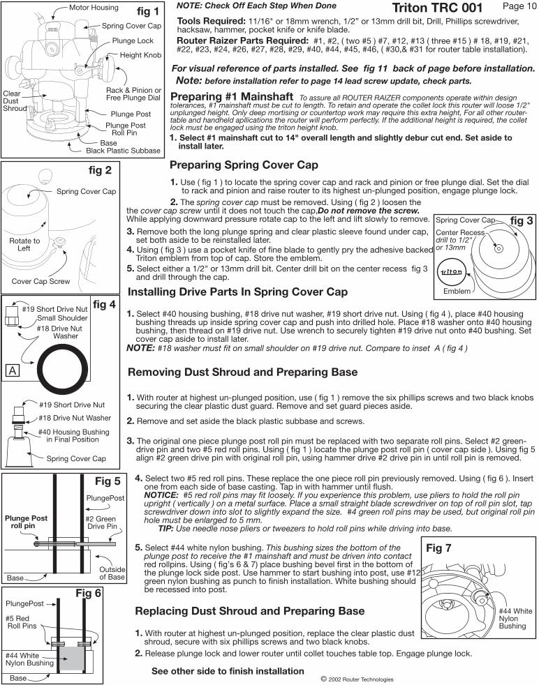
Tools Required: 11/16" or 18mm wrench, 1/2” or 13mm drill bit, Drill, Phillips screwdriver,hacksaw, hammer, pocket knife or knife blade.Router Raizer Parts Required: #1, #2, ( two #5 ) #7, #12, #13 ( three #15 ) # 18, #19, #21,#22, #23, #24, #26, #27, #28, #29, #40, #44, #45, #46, ( #30,& #31 for router table installation).
Preparing Spring Cover Cap
Preparing #1 Mainshaft To assure all ROUTER RAIZER components operate within designtolerances, #1 mainshaft must be cut to length. To retain and operate the collet lock this router will loose 1/2"unplunged height. Only deep mortising or countertop work may require this extra height, For all other router-table and handheld apllications the router will perform perfectly. If the additional height is required, the colletlock must be engaged using the triton height knob.1. Select #1 mainshaft cut to 14" overall length and slightly debur cut end. Set aside to install later.
Fig 6PlungePost
Outsideof Base
Spring Cover Cap
Emblem
fig 3
Height Knob
Spring Cover Cap
Plunge Post
BaseBlack Plastic Subbase
Motor Housing
Plunge Post Roll Pin
Rack & Pinion orFree Plunge Dial
#40 Housing Bushing in Final Position
#18 Drive Nut Washer
#19 Short Drive Nut
fig 4
Spring Cover Cap
#18 Drive Nut Washer
Small Shoulder#19 Short Drive Nut
Triton TRC 001
Plunge Lock
fig 1
ClearDustShroud
© 2002 Router Technologies
Installing Drive Parts In Spring Cover Cap
See other side to finish installation
Removing Dust Shroud and Preparing Base
Base
#5 Red Roll Pins
Replacing Dust Shroud and Preparing Base
#44 WhiteNylon Bushing
A
1. Use ( fig 1 ) to locate the spring cover cap and rack and pinion or free plunge dial. Set the dial to rack and pinion and raise router to its highest un-plunged position, engage plunge lock.
2. The spring cover cap must be removed. Using ( fig 2 ) loosen thethe cover cap screw until it does not touch the cap,Do not remove the screw.While applying downward pressure rotate cap to the left and lift slowly to remove.
4. Select two #5 red roll pins. These replace the one piece roll pin previously removed. Using ( fig 6 ). Insert one from each side of base casting. Tap in with hammer until flush. NOTICE: #5 red roll pins may fit loosely. If you experience this problem, use pliers to hold the roll pin upright ( vertically ) on a metal surface. Place a small straight blade screwdriver on top of roll pin slot, tap screwdriver down into slot to slightly expand the size. #4 green roll pins may be used, but original roll pin hole must be enlarged to 5 mm. TIP: Use needle nose pliers or tweezers to hold roll pins while driving into base.
1. Select #40 housing bushing, #18 drive nut washer, #19 short drive nut. Using ( fig 4 ), place #40 housing bushing threads up inside spring cover cap and push into drilled hole. Place #18 washer onto #40 housing bushing, then thread on #19 drive nut. Use wrench to securely tighten #19 drive nut onto #40 bushing. Set cover cap aside to install later.NOTE: #18 washer must fit on small shoulder on #19 drive nut. Compare to inset A ( fig 4 )
Center Recessdrill to 1/2"or 13mm
3. Remove both the long plunge spring and clear plastic sleeve found under cap, set both aside to be reinstalled later.4. Using ( fig 3 ) use a pocket knife of fine blade to gently pry the adhesive backed Triton emblem from top of cap. Store the emblem.5. Select either a 1/2" or 13mm drill bit. Center drill bit on the center recess fig 3 and drill through the cap.
1. With router at highest un-plunged position, use ( fig 1 ) remove the six phillips screws and two black knobs securing the clear plastic dust guard. Remove and set guard pieces aside.
2. Remove and set aside the black plastic subbase and screws.
3. The original one piece plunge post roll pin must be replaced with two separate roll pins. Select #2 green- drive pin and two #5 red roll pins. Using ( fig 1 ) locate the plunge post roll pin ( cover cap side ). Using fig 5 align #2 green drive pin with original roll pin, using hammer drive #2 drive pin in until roll pin is removed.
5. Select #44 white nylon bushing. This bushing sizes the bottom of the plunge post to receive the #1 mainshaft and must be driven into contact red rollpins. Using ( fig’s 6 & 7) place bushing bevel first in the bottom of the plunge lock side post. Use hammer to start bushing into post, use #12 green nylon bushing as punch to finish installation. White bushing should be recessed into post.
1. With router at highest un-plunged position, replace the clear plastic dust shroud, secure with six phillips screws and two black knobs.2. Release plunge lock and lower router until collet touches table top. Engage plunge lock.
Page 10
For visual reference of parts installed. See fig 11 back of page before installation.
NOTE: Check Off Each Step When Done
fig 2
Spring Cover Cap
Cover Cap Screw
Rotate to Left
Fig 5PlungePost
Base
Plunge Post roll pin
#2 Green Drive Pin
Fig 7
#44 WhiteNylonBushing
Note: before installation refer to page 14 lead screw update, check parts.
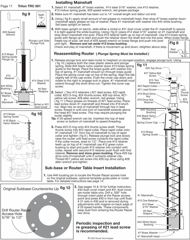
fig 10#13 BrassSpring Guide
# 45 BlackNylon Washer
© 2002 Router Technologies
#1 Mainshaft
#7 Brass Washer
#44 WhiteBushing
#26 Top Drive
#27 Yellow Set Screw
#24 Thumb Screw
#23O-Ring
#15 TwoRetainers
#13 Brass Spring Guide
#15 One Retainer
#5 RedRollpins
#44 White Nylon Bushing
#7 Brass Washer
fig 11
#15Retainer
#13 BrassSpring GuideFlange Up
#29 Speed Wrench
fig 9
Reassembling Router ( Plunge Spring Must be Installed )
1. Release plunge lock and raise router to heighest un-plunged position, engage plunge lock. Using ( fig 10 ) replace both the clear plastic sleeve and plunge spring. Slide #45 black nylon washer down #13 brass spring guide to the flange. Place the brass guide with washer into top of spring. #1 mainshaft should run through brass guide Place the spring cover cap on top of the spring. Align the tab slightly left of the cap screw. Push the cover cap down and rotate to the right to engage lock in place. #1 mainshaft must extend through the short drive nut. Tighten the cover cap screw.
2. Select ( Two #15 retainers ) #21 lead screw, #22 rapid collar, #23 O-ring, #24 thumb screw, #26 top drive, #27- yellow set screw, #28 allen wrench, red grease. Using ( fig 11 ) Place grease on threads of #21 lead screw, Place lead screw down #1 mainshaft and thread into #19 short- nut. Align hex on end of mainshaft through hex in lead screw, thread in until one inch of mainshaft extends above the head #21 lead screw. This may require plunging the router slightly.Tip: # 29 speed wrench can be inserted into top of lead screw or bottom of mainshaft to speed threading.
fig 12
#5 Red Rollpins
4. With base upright on bench, slide either a nickel or #31 dust cover under the #1 mainshaft to assure it is tight against the white bushing. Using ( fig 9 ) place #14 steel 3/16" washer on #1 mainshaft and drop down mainshaft into post. Place #15 retainer teeth up on top of mainshaft. Use #13 brass spring guide with flange up to start and push the retainer down the shaft and into the post. When brass flange meets top of post, set end of #29 speed wrench on brass flange and push into post until tight. Remove and set aside #13 brass bushing. Check end play of mainshaft, if there is movement up and down, retighten above step.
3. Using ( fig 8 ) apply small amount of red grease on mainshaft head, then drop #7 brass washer down mainshaft apply grease on top of washer. Place #1 mainshaft with washer into #44 white bushing. Set base upright on bench.
1. Select #1 mainshaft, #7 brass washer, #14 steel 3/16" washer, one #15 retainer, #13 hollow spring guide, #29 speed wrench, red grease package.2. Make sure #1 mainshaft has been cut to 14" overall length and debur cut end.
Sub-base or Router Table Insert Installation
1. Use #46 locating pin to locate the Router Raizer access hole on the original subbase, optional template guide plate or router table. For detailed instructions see page 14.
#14 Steel 3/16 Washer
#14 Steel3/16" Washer
Page 11 Triton TRC 001
Plunge Lock Side Plunge Post
Nickel or #31 Dust Cover
Teeth Up
3. Press #23 O-ring onto #24 thumb screw shaft. Thread thumb screw into #22 rapid collar. Place rapid collar onto #1 mainshaft 1/2" from top of mainshaft to top of rapid collar and tighten ( fig 9 ). Release plunge lock and slowly raise the router until lead screw contacts the rapid collar. If the collar moves, reset to 1/2". Place one #15 retainer teeth up on top of #1 mainshaft use #12 green nylon bushing to start and push #15 retainer into contact with collar, repeat with second #15 retainer push flush with first retainer. Remove and store green bushing. Place #26 top drive onto #1mainshaft until it contacts retainer clip, Thread #27 yellow set screw into #26 top drive using #28 allen wrench and tighten.
Fig 8
RedGrease
#22 Rapid Collar#21 Lead Screw
#19 Short Drive Nut
#40 Housing Bushing
#1 Mainshaft
#18 Drive Nut Washer
#1 Mainshaft Head
#45 Black Nylon Washer
Spring Cover Cap
Installing Mainshaft
Periodic inspection andre greasing of #21 lead screwis recommended.
Original Subbase Countersinks Up
Drill Router RaizerAccess Hole5/16" to 1/2"
2. See pages 15 & 16 for further instruction, #30 dust cover insert and #31 dust cover, are router table only. Drill a .500" hole through insert plate at the Raizer access point and press #30 in from top until flush. # 31 sets in #30 and is removed during adjustments with magnet on back edge of # 29 speed handle. These components keep dust from entering the Router Raizer hex drive.
Pow
erC
ord
Fold Down
Fold
Down
Pow
erC
ord
Fold Down
Fold
Down
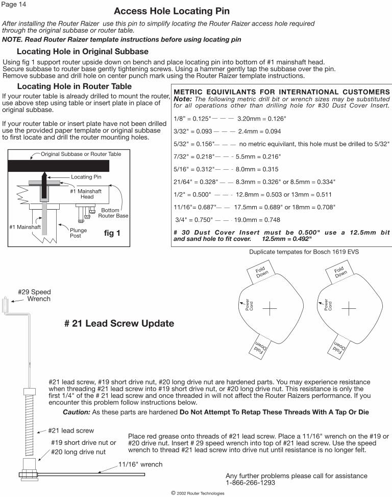
#21 lead screw
#19 short drive nut or#20 long drive nut
# 21 Lead Screw Update
#21 lead screw, #19 short drive nut, #20 long drive nut are hardened parts. You may experience resistancewhen threading #21 lead screw into #19 short drive nut, or #20 long drive nut. This resistance is only thefirst 1/4" of the # 21 lead screw and once threaded in will not affect the Router Raizers performance. If youencounter this problem follow instructions below.
Caution: As these parts are hardened Do Not Attempt To Retap These Threads With A Tap Or Die
11/16" wrench
Place red grease onto threads of #21 lead screw. Place a 11/16" wrench on the #19 or#20 drive nut. Insert # 29 speed wrench into top of #21 lead screw. Use the speedwrench to thread #21 lead screw into drive nut until resistance is no longer felt.
Any further problems please call for assistance1-866-266-1293
Page 14Access Hole Locating Pin
PlungePost fig 1
#1 Mainshaft
#1 Mainshaft Head
BottomRouter Base
After installing the Router Raizer use this pin to simplify locating the Router Raizer access hole requiredthrough the original subbase or router table.
Using fig 1 support router upside down on bench and place locating pin into bottom of #1 mainshaft head.Secure subbase to router base gently tightening screws. Using a hammer gently tap the subbase over the pin.Remove subbase and drill hole on center punch mark using the Router Raizer template instructions.
Locating Hole in Original Subbase
Locating Hole in Router TableIf your router table is already drilled to mount the router,use above step using table or insert plate in place oforiginal subbase.
If your router table or insert plate have not been drilleduse the provided paper template or original subbaseto first locate and drill the router mounting holes.
NOTE. Read Router Raizer template instructions before using locating pin
Duplicate tempates for Bosch 1619 EVS
© 2002 Router Technologies
METRIC EQUIVILANTS FOR INTERNATIONAL CUSTOMERSNote: The following metric drill bit or wrench sizes may be substitutedfor all operations other than drilling hole for #30 Dust Cover Insert.
1/8” = 0.125" 3.20mm = 0.126"
3/32" = 0.093 2.4mm = 0.094
5/32" = 0.156" no metric equivilant, this hole must be drilled to 5/32"
7/32" = 0.218" 5.5mm = 0.216"
5/16" = 0.312" 8.0mm = 0.315
21/64" = 0.328" 8.3mm = 0.326" or 8.5mm = 0.334"
1/2" = 0.500" 12.8mm = 0.503 or 13mm = 0.511
11/16"= 0.687" 17.5mm = 0.689" or 18mm = 0.708"
3/4" = 0.750" 19.0mm = 0.748
# 30 Dust Cover Insert must be 0.500" use a 12.5mm bitand sand hole to fit cover. 12.5mm = 0.492"
Locating Pin
Original Subbase or Router Table
#29 Speed Wrench
Original Subbase and Router Table Insert: Mounting Instructions
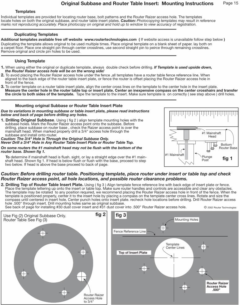
Individual templates are provided for locating router base, bolt patterns and the Router Raizer access hole. The templateslocate holes on both the original subbase, and router table insert plates. Caution: Photocopying templates may result in referencemarks not reproducing accurately. Place photocopy on original and hold up to window to view accuracy of registration.
Templates
Duplicating Templates
Duplicating the template allows original to be used multiple times. Place original template on a blank sheet of paper. lay both ona carpet floor. Place one straight pin through center crosslines, use second straight pin to peirce through remaining crosslines.Remove original and circle pin holes to be used.
Using Template
1. When using either the original or duplicate template, always double check before drilling. If Template is used upside down, the Router Raizer access hole will be on the wrong side!2. To avoid placing the Router Raizer access hole under the fence ,all templates have a router table fence reference line. When aligned to the back edge of the router table insert plate, or fence the router is offset placing the Router Raizer access hole in front of the fence.3. To center template on a router table insert plate, align the center cross lines on the template to the center hole in the insert plate. Measure the center hole in the router table top or insert plate. Center an inexpensive compass on the center crosshairs and transfer the circle to both sides of the template. Tape the template to the insert. Make sure template is on correctly ( see step above ) drill holes.
Page 15
1. Drilling Original Subbase. Using ( fig 2 ) align template mounting holes with the subbase holes. Mark the Router Raizer access point onto the subbase. Before drilling, place subbase on router base , check the Raizer access point is over the mainshaft head. When marked properly drill a 3/4" access hole through the subbase and install onto router.Caution: The 3/4" Hole is Through the Original Subbase Only.Never Drill a 3/4" Hole in Any Router Table Insert Plate or Router Table Top.
fig 2
2. Drilling Top of Router Table Insert Plate. Using ( fig 3 ) Align template fence reference line with back edge of insert plate or fence. Place the template lettering up onto the insert or table top. Make sure router handles and controls are accessible and clear any obstacles. The template may be rotated to any position required, we recommend placing the Router Raizer access hole in front of the fence. When the template is positioned properly, center it to the insert hole by placing a compass on the template center cross lines. Rotate and size the compass until centered in insert hole. Center punch holes onto insert plate. recheck hole locations before drilling. Drill Router Raizer access hole .500" through insert. Drill mounting holes same as original subbase. See back of page for installing #30 dust cover insert and #31 dust cover into .500" Router Raizer access hole.
Mounting original Subbase or Router Table Insert Plate
On some routers the #1 mainshaft head may not be flush with the bottom of therouter base. Shown fig 1. To determine if mainshaft head is flush. sight, or lay a straight edge over the #1 main- shaft head. Shown fig 1. If head is below flush or flush with the base, proceed to step two below. If head is above the base proceed to back of page.
Top of Insert Plate
Due to variations in mounting subbase or table insert plate, please read instructionsbelow and back of page before drilling any holes.
Use Fig (2) Original Subbase Only.Router Table See Fig (3)
Additional templates available free off website www.routertechnologies.com ( If website access is unavailable follow step below )
PlungePost fig 1
#1 Mainshaft
#1 Mainshaft Head
BottomRouter Base
Caution: Before drilling router table. Positioning template, place router under insert or table top and checkRouter Raizer access point, all hole locations, and possible router clearance problems.
Router RaizerAccess Holeto 3/4"
Router RaizerAccess Hole .500"
TemplateCenter Lines
Mounting Holes
Fence Reference Line
fig 3
© 2002 Router Technologies
Drilling Pocket in Back of Router Table Insert Plate. Boring a pocket on the backside of the table insert or router table top providesclearance for the mainshaft head to rotate. Caution; Do not drill pocket over 3/32" deep. Note: The pocket requires a 3/8" or thicker insertplate. If insert plate is thinner than 3/8” or steel, use the 8" X 8" rubber spacer gasket. See instructions bellow.
fig 4
PlungePost
fig 6
#1 Mainshaft
#1 Mainshaft Head
Router Base
8" X 8"Rubber Gasket
Subbaseor Router Table Insert Plate
Page 16
1. Using ( fig 7 ) select #30 dust cover insert ( 1/2" dia, X 3/16" tall, turned aluminum ring ) and #31 dust cover ( 3/8" dia. X 1/8 thick stamped steel plug ) From top of insert plate, press #30 cover insert into the .500" Router Raizer access hole until flush.Tip: If cover insert fits loosely, secure with drop of Super Glue® or Krazy Glue®.
Top Install #30Dust CoverInsert StopRing Down
Stop Ring
.500"Router Raizer Access Hole ( White )
Mounting Holes
fig 5
3/4" dia. X 3/32" Deep Pocket ( Black )
Back of Insert Plate
3. Place #31 dust cover into #30 dust cover insert. Using ( fig’s 7 & 8 ) remove #30 dust cover with magnet on back of #29 speed wrench. With dust cover on speed wrench, insert wrench to make adjustments. To reinstall dust cover, place cover into insert and slide wrench away. Caution: Remove dust cover with speed wrench before removing router from table or cleaning table with vacuum sweeper.
2. Mount router to insert plate and install into table
Side view of insert or table top
3/4" Pocket
1/2" Hole Through Insert Plate or Table Top
#30 DustCover InsertTop Side
Bottom Side
#31 Dust Cover#30 Dust Cover Insert
fig 8fig 7
#29 Speed Wrench
Magnet
Insert Plate
© 2002 Router Technologies
1. With template properly located on insert or table top, center punch on crosshairs all router mounting holes and the Router Raizer access. Using a 1/8" drill bit, drill the Router Raizer access hole through the insert or table top. Turn insert or table top over ( fig 5 ) locate the 1/8" raizer access hole. Center a 3/4" spade or forsner bit on the 1/8" hole and drill a pocket deep enough for the #1 mainshaft head to turn freely. Turn insert or table top over. Center a .500" drill bit on the 1/8" hole and drill completely throgh into the 3/4" pocket. Finish by drilling and countersinking remaining holes, and installing the dust cover insert. See below for instructions.Caution: Do not drill pocket over 3/32" deep. #30 dust cover insert must be installed into top of .500" Raizer access hole. See installing dust cover insert below.
If mainshaft head is not flush with the base, use step below or rubber spacer gasket for mounting to table insert or router table top.
Using the 8" X 8" Rubber Gasket
The 8" X 8" rubber gasket is provided for spacing #1 mainshaft head.
1. The easiest way to prepare the gasket is to first drill the Router Raizer access hole through the original subbase. Place the rubber gasket on a scrap piece of wood. Align the pre-punched 3/4" gasket hole and the Raizer access hole in subbase. Using ink pen, transfer mounting hole locations to the gasket. Using a utility knife or razor blade, hold the subbase in position while cutting around inside and outside of the subbase Remove subbase and cut mounting holes. Using ( fig 6 ) place the gasket between the router base and subbase or insert. Tip: mounting holes can be cut as square holes. If original subbase is unavailable the template may be used to cut the gasket.
Installing the Dust Cover Insert
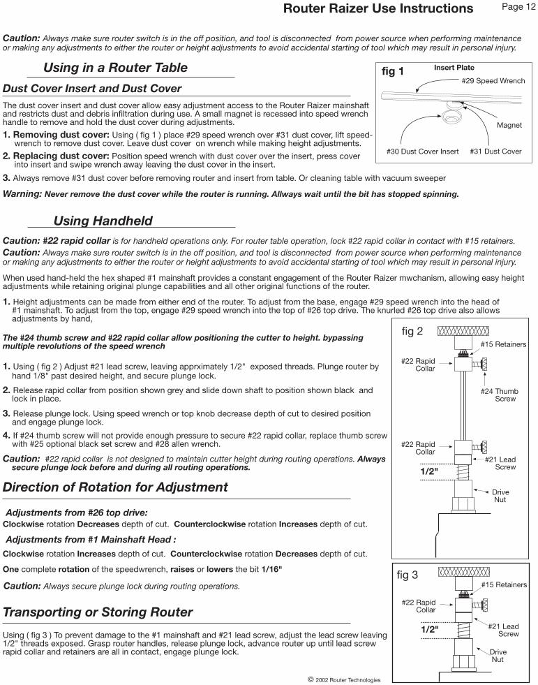
Router Raizer Use Instructions Page 12
When used hand-held the hex shaped #1 mainshaft provides a constant engagement of the Router Raizer mwchanism, allowing easy heightadjustments while retaining original plunge capabilities and all other original functions of the router.
Using Handheld
Using in a Router Table
Caution: Always make sure router switch is in the off position, and tool is disconnected from power source when performing maintenanceor making any adjustments to either the router or height adjustments to avoid accidental starting of tool which may result in personal injury.
Dust Cover Insert and Dust CoverThe dust cover insert and dust cover allow easy adjustment access to the Router Raizer mainshaftand restricts dust and debris infiltration during use. A small magnet is recessed into speed wrenchhandle to remove and hold the dust cover during adjustments.
1. Removing dust cover: Using ( fig 1 ) place #29 speed wrench over #31 dust cover, lift speed- wrench to remove dust cover. Leave dust cover on wrench while making height adjustments.
Caution: Always make sure router switch is in the off position, and tool is disconnected from power source when performing maintenanceor making any adjustments to either the router or height adjustments to avoid accidental starting of tool which may result in personal injury.
Drive Nut
#22 Rapid Collar
#31 Dust Cover#30 Dust Cover Insert
fig 1#29 Speed Wrench
Magnet
Insert Plate
#21 Lead Screw
Drive Nut
#22 Rapid Collar
#22 Rapid Collar
2. Replacing dust cover: Position speed wrench with dust cover over the insert, press cover into insert and swipe wrench away leaving the dust cover in the insert.
3. Always remove #31 dust cover before removing router and insert from table. Or cleaning table with vacuum sweeper
Warning: Never remove the dust cover while the router is running. Allways wait until the bit has stopped spinning.
Direction of Rotation for Adjustment
One complete rotation of the speedwrench, raises or lowers the bit 1/16"
Caution: Always secure plunge lock during routing operations.
Caution: #22 rapid collar is for handheld operations only. For router table operation, lock #22 rapid collar in contact with #15 retainers.
1. Height adjustments can be made from either end of the router. To adjust from the base, engage #29 speed wrench into the head of #1 mainshaft. To adjust from the top, engage #29 speed wrench into the top of #26 top drive. The knurled #26 top drive also allows adjustments by hand,
The #24 thumb screw and #22 rapid collar allow positioning the cutter to height. bypassingmultiple revolutions of the speed wrench
1. Using ( fig 2 ) Adjust #21 lead screw, leaving apprximately 1/2" exposed threads. Plunge router by hand 1/8" past desired height, and secure plunge lock.
© 2002 Router Technologies
fig 3
fig 2
2. Release rapid collar from position shown grey and slide down shaft to position shown black and lock in place.
3. Release plunge lock. Using speed wrench or top knob decrease depth of cut to desired position and engage plunge lock.
4. If #24 thumb screw will not provide enough pressure to secure #22 rapid collar, replace thumb screw with #25 optional black set screw and #28 allen wrench.
Caution: #22 rapid collar is not designed to maintain cutter height during routing operations. Always secure plunge lock before and during all routing operations.
Adjustments from #26 top drive:Clockwise rotation Decreases depth of cut. Counterclockwise rotation Increases depth of cut.
Adjustments from #1 Mainshaft Head :
Clockwise rotation Increases depth of cut. Counterclockwise rotation Decreases depth of cut.
Transporting or Storing Router
1/2"
#24 Thumb Screw
#15 Retainers
1/2"Using ( fig 3 ) To prevent damage to the #1 mainshaft and #21 lead screw, adjust the lead screw leaving1/2" threads exposed. Grasp router handles, release plunge lock, advance router up until lead screwrapid collar and retainers are all in contact, engage plunge lock.
#15 Retainers
#21 Lead Screw
This instruction manual covers several different makes and models of plunge routers. The instructions are written fora person with some mechanical ability. If you understand the parts and operation of a plunge router, installing theRouter Raizer is not difficult. Before beginning installation compare the illustrations and photos to your router, originalsubbase or router table insert plate. Understand the location and function of both original and Router Raizer parts.Keep all spare parts, instruction manual and templates for future reference. The Router Raizer can be removed fromany router and reinstalled into another.
Responsibility of the Owner
1. The responsibility of the owner is to follow the instructions, cautions, and warnings bellow and in the instructions
2. Know and understand the location of both original and Router Raizer parts.
3. Follow all the assembly instructions carefully.
4. Correctly adjust the components making sure the plunge action is smooth and plunge lock operates properly.
5. Carefully read and follow all notes, tips, cautions and warnings.
6. Make sure all operators of the Router Raizer know how to correctly use it.
Important: Read, understand and follow instructions to avoid personal injury.
Caution: Before and during installation of Router Raizer make sure power switch is in the off position and tool isdisconnected from power source to avoid accidental starting of the tool which may result in personal injury.
Caution: Always make sure router power switch is in the off position and disconnected from power sourcebefore and during any adjustments to the router or Router Raizer.
Warning: Never remove or reinstall #31 dust cover or make any depth of cut adjustments from either end of#1 mainshaft until router power switch is off, cutting tool has completely stopped rotating and tool is disconnectedfrom power source.
Caution: Always secure plunge lock before and during routing operations.
ROUTER TECHNOLOGIESLIMITED TWO YEAR WARRANTY
Router Technologies warrants the Router Raizer to be free from defects in material andworkmanship for a period of Two ( 2 ) Years from the original date of purchase to originalowner. Our responsibility under this warranty is to replace, at no cost, any part whichupon inspection at our facility is found to be defective in either material or workmanship.This warranty does not imply that the product is fit for a particular use or application, thiswarranty does not apply to parts which have been modified, altered, misused, damagedby improper storage. It also does not cover loss of parts during use, or mechanicaladjustments which are covered in the instruction manual. In no event shall Router -Technologies be liable for any indirect, incidental or consequential damages from thesale or use of the product. This disclaimer applies both during and after the term of thewarranty.
This warranty is your only remedy and parts are to be returned prepaid to our facility for inspection at Router Technologies, 2729 Delaware Ave, Des Moines, IA. 50317.This warranty gives you specific legal rights, and you may have other rights which mayvary from state to state. Any legal actions must be brought in Polk County Iowa.
© 2002 Router Technologies
Page 13
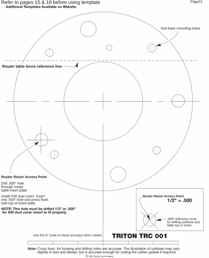
TRITON TRC 001
Additional Templates Available on Website
1/2" = .500Router Raizer Access Point
.500" reference circlefor drilling subbase andtable top or insert.
© 2002 Router Technologies
NOTE: This hole must be drilled 1/2" or .500" for #30 dust cover insert to fit properly.
Sub-base mounting holes
Drill .500" holethrough routertable insert plate
install #30 dust cover insertinto .500" hole and press flushwith top of insert plate
Router table fence reference line
Use this 6" scale to check accuracy when copied
Router Raizer Access Point
Note: Cross lines for locating and drilling holes are accurate. The illustration of subbase may vary slightly in size and design, but is accurate enough for cutting the rubber gasket if required.
Refer to pages 15 & 16 before using template Page21