RYPOS DIESEL EXHAUST PARTICULATE FILTER DPF/ULETRU Thermo ... · DPF/ULETRU Installation Manual –...
32
DPF/ULETRU Installation Manual – Thermo King Part Number 820-0013-00-00 Rypos, Inc., 150 Hopping Brook Road, Holliston, MA 01746 www.rypos.com Tel: 508-429-4552, Fax: 508-429-4553 Page 1 RYPOS DIESEL EXHAUST PARTICULATE FILTER DPF/ULETRU Thermo-King TRU Manual Operation, Installation and Maintenance
Transcript of RYPOS DIESEL EXHAUST PARTICULATE FILTER DPF/ULETRU Thermo ... · DPF/ULETRU Installation Manual –...

DPF/ULETRU Installation Manual – Thermo King Part Number 820-0013-00-00
Rypos, Inc., 150 Hopping Brook Road, Holliston, MA 01746 www.rypos.com
Tel: 508-429-4552, Fax: 508-429-4553 Page 1
RYPOS DIESEL EXHAUST PARTICULATE FILTER DPF/ULETRU
Thermo-King TRU
Manual Operation, Installation and Maintenance

DPF/ULETRU Installation Manual – Thermo King Part Number 820-0013-00-00
Rypos, Inc., 150 Hopping Brook Road, Holliston, MA 01746 www.rypos.com
Tel: 508-429-4552, Fax: 508-429-4553 Page 2
YOUR RIGHT TO MAINTENANCE INFORMATION
The Air Resources Board requires that Rypos Inc. provide detailed maintenance information for the diesel emission control system upon delivery to the end-user pursuant to section 2706(h)(2), Title 13, California Code of Regulations, at no
additional cost to the owner. If you do not already have this information, contact Rypos at 1-508-429-4552.
THE IMPORTANCE OF ENGINE MAINTENANCE
Proper engine maintenance is critical for the proper functioning of your diesel emission control strategy. Failure to document proper engine maintenance, including oil
consumption records, may be grounds for denial of a warranty claim for a failed component of a diesel emission control strategy.
THE IMPORTANCE OF PROPERLY MAINTAINING A DIESEL
EMISSION CONTROL STRATEGY
Proper maintenance is critical for the diesel emission control strategy to function as intended. Failure to document proper diesel emission control strategy maintenance,
including cleaning and/or ash removal of the system, replacement of consumables, and replacement of broken/failed parts, may be grounds for denial of a warranty claim for a
failed component of a diesel emission control strategy.
CAUTION Before beginning this installation, take a few minutes to read the entire instructions.
Check that all necessary materials, units, and kits that are listed in the application guide are on hand. Check the website www.rypos.com frequently for Rypos product updates and information
This manual is the sole property of RYPOS, Inc. (RYPOS) Copying, faxing, e‐mailing, altering or in any way reproducing this manual in whole or in part is forbidden without the express written consent of RYPOS. RYPOS reserves the right to change or alter any and all specifications at anytime without prior notification and without incurring any obligation to such changes. The information included in this publication is believed to be accurate at the
time of publication; however, no responsibility is taken by RYPOS unless expressly given
DPF/ULETRU Installation Manual – Thermo King Part Number 820-0013-00-00
Rypos, Inc., 150 Hopping Brook Road, Holliston, MA 01746 www.rypos.com
Tel: 508-429-4552, Fax: 508-429-4553 Page 3
TABLE OF CONTENTS
Installation Information
New CARB Dealer/Installer Requirements……………………………4
Pre-installation requirements and documentation……………………5
Safety precautions and required tool list………………………………7
Initial checks……………………………………………………….……8
Removal of existing parts and installation of new parts..………….…8
Electrical connections………………………………………………….15
Start up and final checks……………………………….……………...18
Maintenance Information
Maintenance requirements....…………………………………………19
Ash clean out procedure………………………………………………20
Component swapping and re-designation practices…………………20
Rypos system checklist………………………………………………...21
Troubleshooting
Light bar codes…...……………………………………………………22
Troubleshooting procedure…………………………………………...23
Wiring diagram…………………………………………………….….27
Service Parts
Service parts list…………………………………………………..……26
Component identification photos………………………………….….28
Compatible Engine Models ………………………………………………….29
Warranty Statements and CARB Registration information.………….…..30
DPF/ULETRU Installation Manual – Thermo King Part Number 820-0013-00-00
Rypos, Inc., 150 Hopping Brook Road, Holliston, MA 01746 www.rypos.com
Tel: 508-429-4552, Fax: 508-429-4553 Page 4
New CARB Dealer/Installer Requirements:
Pre-installation compatibility assessment procedures
The following checks need to be made PRIOR to installing a DPF/ULETRU filter onto a TRU unit:
1) Inspect the engine for signs of poor maintenance, (oil leaks, oil filter over 1 year old, oil with more than recommended hours on it, dirty air filter, worn belts, etc)
2) Inspect the tailpipe for signs of oil contamination (is the soot oily? Does it look like grease?)
3) The CARB Executive Order requires a check for oil consumption and the condition of the injectors. An easy, functional way to do this is to inspect the exhaust plume for signs of high PM emissions and oil burning. There should be no visible color to the exhaust during steady speed operation. The DPF/ULETRU will not work on an engine that is producing excessive smoke, which is a sign that the engine may have a stuck injection pump plunger, broken injection pump nozzle, or have excessive oil consumption. All repairs to the engine must be made prior to filter installation.
4) Check the engine hours, if over 25000, please advise the customer that they could have engine related problems in the near future due to the age of the engine and that a filter may not be the best means of compliance.
In order to prevent excessive PM emissions rates, engine emissions-related maintenance, such as injector replacements, air filter replacements and valve adjustments, should be performed in accordance with OEM required maintenance schedules. Such maintenance is necessary to prevent RYPOS DPF/ULETRU system failure and inefficient fuel consumption. The DPF/ULETRU filter will plug up if the engine is producing visible smoke on a continuous basis. NOTE: short smoke puffs seen during start up and speed changes are normal.
Written statement of Compatibility If the candidate engine is found to be compatible with the Diesel Emission Control Strategy (DECS), the party conducting the pre-installation compatibility assessment must provide the end user with a written statement stating its compatibility based upon the CARB Executive Order (EO) and the DECS manufacturers pre-installation instructions no later than the date of installation. Dealers/Installers: Please use the form on the next page (copy also at the end of the manual) to document the pre-installation compatibility assessment. This form must be:
1) Signed and a copy given to the customer/end user of the DPF/ULETRU system 2) Signed copy must be sent to Rypos for warranty registration and filing. Any warranty claims submitted for a system that is not registered with Rypos will be the responsibility of the dealer/installer. The pre-installation compatibility/warranty registration must be on file at Rypos in order to have Rypos warranty coverage. 3) The dealer/installer must keep a copy of the pre-installation compatibility assessment on file and be able to produce it to CARB upon request.

DPF/ULETRU Installation Manual – Thermo King Part Number 820-0013-00-00
Rypos, Inc., 150 Hopping Brook Road, Holliston, MA 01746 www.rypos.com
Tel: 508-429-4552, Fax: 508-429-4553 Page 5
Pre‐Installation Compatibility Assessment and Warranty Registration Form
1) Verify that the engine year and family is listed in the Compatible Engine Models Table
2) Inspect the TRU unit for oil leaks, general maintenance, signs of oil in exhaust, hrs on the oil and oil
filter, condition of air filter, color of smoke during steady state operation at both high and low speed)
3) Fill out ALL information below, sign statement, give one copy to the customer and send one copy
to Rypos (Warranty coverage for incomplete information will be the responsibility of the installer!)
TRU owner’s company name and address:________________________________________________
Contact name_____________________ phone:________________ E‐mail______________________
Installer’s name:_____________________ phone:_______________ E‐mail_____________________
Installation date:_____________ TRU readings: Switch on hours___________ Engine hours________
TRU model name: (SB210, SB300 etc.):_________________(CANNOT BE INSTALLED ON MULTI‐TEMP)
TRU serial number:_________________________________ Date in Service:______________
TRU engine serial number (From data label on engine and unit frame):_________________________
Rypos DPF/ULETRU serial number: U___ ___ ___ ___ Date of Manufacture___________________
Current ARB #_________________________ Bosch Alternator Serial number:___________________
Statement of Compatibility: “I have inspected the engine for signs of poor maintenance (oil leaks, oil filter over 1 year old, oil with more than recommended hrs on it, dirty air filter, worn belts, etc). I have looked at the exhaust soot for oil content, and I have observed the color of the exhaust both in high and low speed (No color should be visible in steady state operation) and I hereby affirm that the TRU listed above has met ALL of the above compatibility criteria for installation of DPF/ULETRU”
________ YES, ALL CRITERIA ACCEPTABLE ________ NO, THERE ARE ISSUES WITH THE UNIT THAT
MUST BE ADDRESSED BEFORE A DPF/ULETRU MAY BE INSTALLED (LIST ISSUES__________________)
Statement of Warranty: “I hereby warrant that the installation of the Rypos DPF/ULETRU is free
from defects in workmanship or materials which cause the diesel emission control system to fail to
conform to the emission control performance level it was verified to, or to the requirements in the
California Code of Regulations, Title 13, Sections 2700 to 2706. The warranty period and the extent
of the warranty coverage provided by me must be the same as the warranty provided by Rypos, Inc.,
and the same exclusions must apply”
SIGNED__________________________________________________ DATE_____________
Rypos Family Name for Verification: CA/RYP/2011/PM3+/N00/TR/DPF01 Customer Copy

DPF/ULETRU Installation Manual – Thermo King Part Number 820-0013-00-00
Rypos, Inc., 150 Hopping Brook Road, Holliston, MA 01746 www.rypos.com
Tel: 508-429-4552, Fax: 508-429-4553 Page 6
OWNERS WARRANTY RESPONSIBILITY
As the engine owner, you are responsible for performing the required maintenance described in your owner’s manual. Rypos, Inc. recommends that you retain all maintenance records and receipts for maintenance expenses for your vehicle, engine, or equipment, and diesel emission control system. If you do not keep your receipts or fail to perform all scheduled maintenance, Rypos, Inc. may have grounds to deny warranty coverage. You are responsible for presenting your vehicle, equipment, or engine, and diesel emission control system to a Rypos, Inc. dealer as soon as a problem is detected. The warranty repair or replacement should be completed in a reasonable amount of time, not to exceed 30 days. If a replacement is needed, this may be extended to 90 days should a replacement not be available, but must be performed as soon as a replacement becomes available.
If you have questions regarding your warranty rights and responsibilities, you should contact Rypos, Inc. at 1-508-429-4552 or the California Air Resources Board at 9528 Telstar Avenue, El Monte, California 91731, or (800) 363-7664, or electronic mail: [email protected].
DPF/ULETRU Installation Manual – Thermo King Part Number 820-0013-00-00
Rypos, Inc., 150 Hopping Brook Road, Holliston, MA 01746 www.rypos.com
Tel: 508-429-4552, Fax: 508-429-4553 Page 7
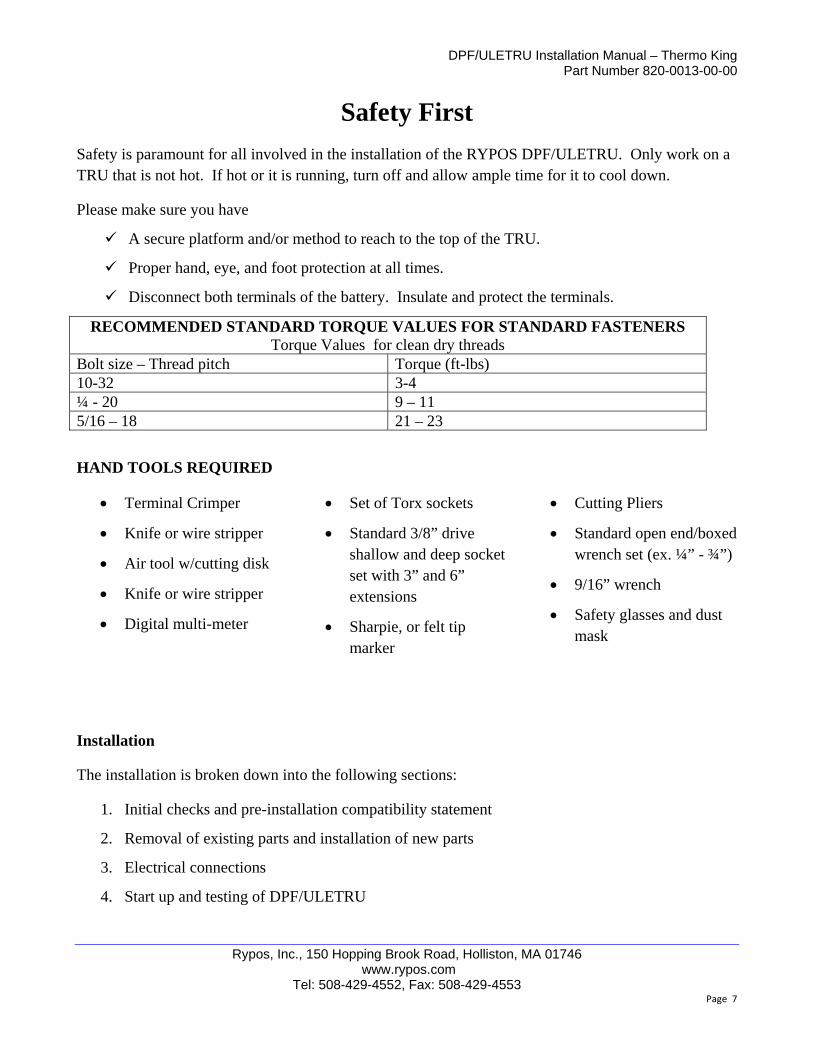
Safety First
Safety is paramount for all involved in the installation of the RYPOS DPF/ULETRU. Only work on a TRU that is not hot. If hot or it is running, turn off and allow ample time for it to cool down.
Please make sure you have
A secure platform and/or method to reach to the top of the TRU.
Proper hand, eye, and foot protection at all times.
Disconnect both terminals of the battery. Insulate and protect the terminals.
RECOMMENDED STANDARD TORQUE VALUES FOR STANDARD FASTENERS Torque Values for clean dry threads
Bolt size – Thread pitch Torque (ft-lbs) 10-32 3-4 ¼ - 20 9 – 11 5/16 – 18 21 – 23
HAND TOOLS REQUIRED
Terminal Crimper Set of Torx sockets Cutting Pliers
Knife or wire stripper
Air tool w/cutting disk
Knife or wire stripper
Digital multi-meter
Standard 3/8” drive shallow and deep socket set with 3” and 6” extensions
Sharpie, or felt tip marker
Standard open end/boxed wrench set (ex. ¼” - ¾”)
9/16” wrench
Safety glasses and dust mask
Installation
The installation is broken down into the following sections:
1. Initial checks and pre-installation compatibility statement
2. Removal of existing parts and installation of new parts
3. Electrical connections
4. Start up and testing of DPF/ULETRU

DPF/ULETRU Installation Manual – Thermo King Part Number 820-0013-00-00
Rypos, Inc., 150 Hopping Brook Road, Holliston, MA 01746 www.rypos.com
Tel: 508-429-4552, Fax: 508-429-4553 Page 8
Initial Checks
Unless otherwise specified, all instructions are given from the front view of the TRU.
1. Complete the pre-installation compatibility checks and fill out the forms above, sign and give copy to customer and send one to Rypos.
2. Compatible Thermo-King TRU models are: SB190, SB210, SB230, SB300, SB400
MULTI-TEMP UNITS ARE NOT COMPATIBLE WITH DPF/ULETRU
3. Thermo-King units that are NOT supported by this product include: SPECTRUM, units older than 2003 and anything else not specifically mentioned above.
4. For the RYPOS DPF/ULETRU to operate properly, the proper alternator, alternator pulley, and wiring must be installed in the TRU. The wiring will be supplied in the installation kit. Part Numbers for RYPOS TK Alternator and Belts
Rypos Part Number Description
175-0017-00-00 Alternator, 120 amp (Bosch AL9120N, Thermo King 45-2258)
775-0005-00-00 Pulley, 2.62" OD – (Purchase from Rypos)
Suggested Belts
780-0004-00-00 Thermo-king belt 78-1341
780-0007-00-00 Optibelt, Super X-POWER M=S, XPA 1132
Rypos strongly recommends using the Rypos and or Thermo-King part numbers supplied above in order to be sure that the Rypos DPF/ULETRU system will work properly.
Removal of Existing Parts and Installation of New Parts
For safety, disconnect both the positive and negative terminals from the battery(s) and protect the terminals from accidental contact or falling parts. Remove the front and right side doors from the unit to allow easier access to all areas of the unit while performing the installation. It may not be necessary to remove the large center door, but it may make the installation easier (won’t have to repeatedly open and close it)
1. Remove muffler and exhaust pipe: Spraying some penetrating oil (WD40 or similar) onto the exhaust joints before starting will help loosen them up and make disassembly much easier. Unbolt the muffler mounting bolts and the muffler and exhaust pipe clamps and remove the muffler and exhaust pipe. Leave the existing TK flex pipe connected to the engine. Cover the end of the pipe with a cloth or paper cup so nothing can fall down the pipe.

DPF/ULETRU Installation Manual – Thermo King Part Number 820-0013-00-00
Rypos, Inc., 150 Hopping Brook Road, Holliston, MA 01746 www.rypos.com
Tel: 508-429-4552, Fax: 508-429-4553 Page 9
2. Mark the upper cowling using the template provided and a Sharpie or felt tip marker. Cut out the upper right hand corner of the fiberglass material with the shroud still bolted in place. This will provide support while you are cutting. IMPORTANT! Use an appropriate dust mask and safety glasses for this task!
Once the pieces have been cut out, remove the cowling from the unit using the Torx sockets and regular wrenches. Set the cowling aside. Remove the 2 bolts/nuts that hold the radiator baffle plate in place and set the plate and bolts/nuts on top of the trailer.
3. Remove the old alternator and belt and install the new Bosch 120 amp alternator along with the new 2 5/8” alternator pulley. If the unit already has a 120 amp alternator, you will still need to change the alternator pulley in order for the system to work properly.
Set the template on top of the unit against the trailer and line up the corner of the template with the edge of the fiberglass opening. Use a marker or sharpie to trace the shape of the template onto the cowling. Then use a saw or cutting disk to cut out the pieces of the cowling as shown.
Loosen these bolts to slide the assembly back (2 in front and 2 underneath in back)
Idler assembly
NOTE: Since the large idler assembly is loose, it may be a good time to update all of the belts on the unit.

DPF/ULETRU Installation Manual – Thermo King Part Number 820-0013-00-00
Rypos, Inc., 150 Hopping Brook Road, Holliston, MA 01746 www.rypos.com
Tel: 508-429-4552, Fax: 508-429-4553 Page 10
4. In order to remove the alternator belt, you will need to loosen the large idler pulley assembly and slide it backwards. (see above) There are 2 bolts in front and 2 in back underneath the assembly. Remove the large drive belt (or slide it off of the crank pulley) and then remove and replace the alternator belt. Since the large idler assembly is loose, the customer may want to change the drive belts. If so, do it now.
5. After the belts are installed, slide the idler assembly forward by pulling on the ‘handle’ firmly to tighten the belts. Check the belts for tension and then re-tighten the 4 bolts that secure the idler assembly in place. Tighten the alternator into position, making sure the belt is tight.
6. Remove 3 of the 4 nuts holding the large door latch assembly in place and install the power
solenoid mounting bracket in place as shown. Re-install the nuts and tighten firmly. 7. Install the DOC/exhaust pipe onto the OEM flex exhaust pipe. Then secure the pipe to the
back wall with a bolt at the attachment point shown below.
Leave this one alone to keep the latch hardware securely positioned. Bracket has a through hole that fits over the top of this nut
Remove these 3 nuts/washers in order to slide the bracket into place
DOC/exhaust pipe mounting to back wall of unit. Start the bolt and turn in a few threads to hold the pipe in place, but do not tighten yet.
DOC
DOC
Slide OEM flex pipe into DOC/pipe assembly. Muffler clamp may be positioned, but do not tighten yet as pipe may need to be adjusted.
Front view of power solenoid bracket

DPF/ULETRU Installation Manual – Thermo King Part Number 820-0013-00-00
Rypos, Inc., 150 Hopping Brook Road, Holliston, MA 01746 www.rypos.com
Tel: 508-429-4552, Fax: 508-429-4553 Page 11
8. Pre assemble the filter mounting brackets onto the filter with the ¼”-20 bolts and washers
supplied in the accessory kit as shown below. Set the filter/ECU assembly up on top of the unit approximately as shown below. It is easiest to fold the ECU over on top of the filter and carry the assembly up to the top of the unit.
9. Connect the DOC/exhaust pipe to the filter, sliding the pipes together as far as they can go, but do not clamp tightly yet. (Clamp shown in final position after all adjustments made)
Exhaust pipe from DPF
Exhaust pipe/DOC assembly
Pre-assemble brackets to the filter as shown, long in front, and short to the back
Set filter into place approximately as shown

DPF/ULETRU Installation Manual – Thermo King Part Number 820-0013-00-00
Rypos, Inc., 150 Hopping Brook Road, Holliston, MA 01746 www.rypos.com
Tel: 508-429-4552, Fax: 508-429-4553 Page 12
10. Mount the rear plate of the filter and the external pressure transducer bracket, and the TK radiator baffle bracket with the 2 bolts and nuts removed after the cowling was cut. See below. Start the nuts on the bolts, but do not tighten completely yet, as the filter may need to move around a bit to get into final position.
11. Connect the pressure tube to the blue hose as shown and secure with cable ties. Insert stainless steel back pressure tube into compression fitting and tighten with 9/16” wrench.
12. The filter should be sitting almost perfectly horizontal now (as shown in the photo above). If it is not, try adjusting the fit between the exhaust pipe and filter in order to get the filter horizontal. If the filter is horizontal, tighten the bolt holding the DOC /pipe assembly to the back wall of the unit. The filter should look square with the unit as shown below
2 bolts and nuts that hold TK radiator baffle plat in place in the upper right corner of the unit. Snug up, but do not tighten yet
Keep the pressure tube on a gradual down hill slope as shown. If any condensate forms in the tube, it will drain back to the filter. Make sure there are not kinks in the blue hose!
Install the ECU mounting foot to the ECU bracket as shown, leave bolts loose.

DPF/ULETRU Installation Manual – Thermo King Part Number 820-0013-00-00
Rypos, Inc., 150 Hopping Brook Road, Holliston, MA 01746 www.rypos.com
Tel: 508-429-4552, Fax: 508-429-4553 Page 13
13. When the filter is horizontal, snug the bolt on the mounting brackets so that the bottom of the
bracket is sitting flat on the mounting surface, and so that the bracket is up tight to the filter. Tighten the DOC/exhaust pipe mounting screw and make sure filter is still positioned horizontal and square to the unit.
14. Use the self-drilling screws supplied with the kit to mount the filter into position. Tighten mounting bracket bolts to the filter, and install upper exhaust pipe clamp between filter and DOC pipe. Tighten the 2 bolts/nuts that hold the pressure transducer in place at the rear of the filter.
15. Position the ECU so that the ECU mounting bracket is about ¼”behind the vertical surface of the TRU evaporator pod. The wires should be out of the way and not rub against anything.
Self drilling screws to mount filter to unit
Snug the bolts with the filter horizontal
~1/4” between vertical surface and ECU bracket

DPF/ULETRU Installation Manual – Thermo King Part Number 820-0013-00-00
Rypos, Inc., 150 Hopping Brook Road, Holliston, MA 01746 www.rypos.com
Tel: 508-429-4552, Fax: 508-429-4553 Page 14
16. Mount the ECU to the frame using the self drilling screws as shown below
17. With the ECU level, mount the front mounting leg to the ECU bracket and to the evaporator pod. Use caution as self drilling screws could strip through the fiberglass pod. Tighten the bolts to the ECU bracket, making sure the ECU is still level.
18. Use adel clamps and self drilling screws to secure the wires on the top of the unit as shown. Plug the pressure transducer connector into the transducer and lock the connector in place.

DPF/ULETRU Installation Manual – Thermo King Part Number 820-0013-00-00
Rypos, Inc., 150 Hopping Brook Road, Holliston, MA 01746 www.rypos.com
Tel: 508-429-4552, Fax: 508-429-4553 Page 15
Electrical Connections:
Most of the wiring for the DPF/ULETRU is done at the factory. Some simple wiring and connections need to be made here.
1. Run signal: On the front of the engine identify the fuel shut off solenoid. Plug the Rypos harness in between the solenoid connector and the TK harness as shown below. Route the harness along with the other unit wires and connect the ring terminal end to the power solenoid
2. Power Solenoid:
Secure the run signal wire, but Do not cable tie to fuel lines. Tie to the clamps holding the fuel lines, not the lines
Connect Rypos harness between run solenoid and TK harness
Run light panel wires along with unit wiring up to ECU, cable tie in place
Run solenoid wire
Positive wire going from power solenoid to 100 amp fuse
Positive wire going up to ECU
Negative wire from alternator to ECU Positive wire from alternator
Rypos run solenoid wire connected to small terminal on solenoid
Run solenoid wire from fuse outlet terminal to ECU

DPF/ULETRU Installation Manual – Thermo King Part Number 820-0013-00-00
Rypos, Inc., 150 Hopping Brook Road, Holliston, MA 01746 www.rypos.com
Tel: 508-429-4552, Fax: 508-429-4553 Page 16
3. Connect the Rypos ECU negative (black) wire, the Rypos battery negative wire, and the TK
unit negative wires to the negative post on the alternator (3 wires total). 4. Install the short Rypos positive (red) wire along with the TK positive wire to the alternator.
Connect the other end of the positive wire to the large terminal on the power solenoid that is open. (The wire going to the fuse is on the other side).
5. Connect the ECU power wire (small) and the ECU hi current wire (red) from the outlet side of the fuse up to the ECU. Plug the small wire into the appropriate ECU connector. (see above)
6. Remote light panel: The remote light panel is an indicator of system operation. It should be installed on the outside of the unit in the approximate position of a TRU light bar. Mount the indicator light panel with self drilling screws. Then route the wire along with the unit wires up to the ECU. Cable tie to secure the wire along the way. Plug into ECU connection.
Secure wires going up to the ECU : Secure the wires going up to the ECU and cable tie to adjoining wiring for support. Use and adel clamp to secure the wires to the evaporator pod in order to keep them out of the way of the fan. Using the supplied cable ties secure all wires and cables at this time. See photos below for wire routing and use of clamps to secure wires. (Ref wiring diagram, pg 27)
Use a digital multi-meter to check for any shorts between the positive and negative battery harnesses (ohm out). If a short is found, double check wiring. Do not proceed until all shorts have been fixed.
7. Cable tie all remaining wires to secure them and prevent chafing, etc. 8. Connect the Thermo-King harness wire(s) to the positive (+) terminal on the battery 9. Connect the following wires to the negative (-) wires to the battery at this time.
a. Negative Rypos wire from the alternator b. Original wires from TK harness
Proper position of light bar installed next to the TRU unit and mounted to the trailer
Proper position of Alternator and Rypos decals

DPF/ULETRU Installation Manual – Thermo King Part Number 820-0013-00-00
Rypos, Inc., 150 Hopping Brook Road, Holliston, MA 01746 www.rypos.com
Tel: 508-429-4552, Fax: 508-429-4553 Page 17
Clamp to secure the wires into this position. Keep them out of the way of the fan.
Suggested route for running wires up to the ECU connections.

DPF/ULETRU Installation Manual – Thermo King Part Number 820-0013-00-00
Rypos, Inc., 150 Hopping Brook Road, Holliston, MA 01746 www.rypos.com
Tel: 508-429-4552, Fax: 508-429-4553 Page 18
Start-up and Operation of DPF: 1. Disconnect the speed solenoid (optional) on the TRU unit so that the initial testing of the unit is
conducted at low speed. This will make it easier to hear the solenoid actuate and to be able to hear the engine speed change with the load applied by the alternator during regeneration.
2. Turn on the unit switch to start the TRU engine and verify operation of DPF. The green and yellow light on the indicator panel will light up at solenoid engagement. They will then go out for 40 seconds and come back on when the unit starts a regeneration. Green light verified
3. Approximately 40 seconds after start up the DPF will actuate one flow control solenoid and regenerate one filter element. You will be able to hear the solenoid engage, which will shut off exhaust flow to one of the 2 outlet pipes. The filter will then regenerate for the next 3.5 minutes. While the unit is regenerating, check the low speed rpm, it should be at least 1450 rpm during the regeneration, adjust up if necessary. Write in new low speed during regen
4. The engine will pick up a few rpm in speed after the regeneration is completed. Approximately 10 seconds after the speed increases, the solenoid will open and exhaust will flow through both pipes again. Shut the unit off, wait for a few seconds and turn on again. The unit will go through the same sequence as above, only this time with the other solenoid, and the flow will be shut off to the other outlet pipe. This check will make sure both solenoids are working properly. Both solenoids working properly and the system is regenerating as it should
5. If you have any problems, check out the troubleshooting section for assistance.
Final Checks 1. Double check all connections to make sure they are tight, and make sure all wires are safely
supported and cable tied to prevent excessive motion during unit operation. 2. Reinstall the unit doors and upper cowling, re-connect the speed solenoid (if disconnected for
testing), and re-tighten the alternator belt. 3. Once everything is complete, place the labels as shown below. Clean the surface with a damp
cloth to remove any dirt and wipe dry. Remove tape covering and place the label into position. Press firmly across the entire label to insure good contact. It is suggested to also rivet or use self drilling screws to secure the RYPOS label firmly onto the unit.
4. Set the automatic defrost timer to 1.5 or 3 hours as this helps maintain good filter health.
RYPOS Serial Number Label 120 Amp Alternator Label
Rypos System Label

DPF/ULETRU Installation Manual – Thermo King Part Number 820-0013-00-00
Rypos, Inc., 150 Hopping Brook Road, Holliston, MA 01746 www.rypos.com
Tel: 508-429-4552, Fax: 508-429-4553 Page 19
MAINTENANCE REQUIREMENTS:
Daily or every use: 1) Check the alternator belt tension along with doing all other OEM recommended pre-trip checks
a. Re-tension belt if loose, or replace if belt is worn 2) Check indicator light panel to make sure the green light is on and the yellow is off when the
TRU is running
Quarterly or every 500 hours: 1) Inspect alternator belt, re-tighten if belt is in good condition, replace if belt is showing signs of
wear/checking/cracking 2) Conduct complete system checkout per the ‘RYPOS SYSTEM CHECKLIST’ to insure that
your system is operating properly and save a copy for the maintenance records.
Annual Maintenance: 1) Inspect alternator belt, re-tighten if belt is in good condition, replace if belt is showing signs of
wear/checking/cracking 2) Remove the blue hose from the external pressure transducer and blow air back through it into
the filter to make sure the line is clear 3) Conduct complete system checkout per the ‘RYPOS SYSTEM CHECKLIST’ to insure that
your system is operating properly and save a copy for the maintenance records. 4) Check low speed during regeneration and adjust to 1450 rpm or greater 5) Inspect for ash accumulation and follow procedure below if required
Non-Rypos Maintenance and Replacement parts suggestions:
Belts - Use either the Thermo King 78-1341, or Rypos 780-0007-00-00, (Optibelt XPA 1132)
Alternator - Only use the Bosch 120 amp alternator, which can be purchased from Rypos or Thermo King.
Other alternators have demonstrated shorter operational life and are not recommended.

DPF/ULETRU Installation Manual – Thermo King Part Number 820-0013-00-00
Rypos, Inc., 150 Hopping Brook Road, Holliston, MA 01746 www.rypos.com
Tel: 508-429-4552, Fax: 508-429-4553 Page 20
Ash Cleanout Procedure During the annual maintenance inspection the unit should be checked for ash accumulation. The ash inspection port is located on the right side of the unit (the side near the exhaust inlet pipe). Ash is considered a hazardous waste material and must be collected using a vacuum with a HEPA filter. Follow the ash handling guidelines as prescribed by CARB at www.arb.ca.gov/diesel/tru/documents/ashguide.pdf.
1. The engine should be off before proceeding. 2. Disconnect the positive terminal from the battery to ensure the unit is not operational. 3. Remove the air cleaner to provide better access to the right side of the unit. 4. Open the ½” NPT port and connect a suitable vacuum cleaner hose. 5. Remove the rain caps from the two exhaust pipes. 6. Close off one of the exhaust ports with a 2” cap or tape. 7. Attach a 2” blower hose to the open exhaust port. 8. Manually open the solenoid valve by moving the plunger away from the body of the unit. 9. Turn on the vacuum and the blower and run for 5 minutes. 10. Repeat the same operation on the other side. 11. Remove all hoses and reattach the rain caps to the exhaust pipes. 12. Put anti-seize on the threads of the NPT port plug and reattach. 13. Reattach the air cleaner. 14. Reattach the positive terminal of the battery.
Rypos Component Swapping and Re-Designation Practices Rypos has added specific requirements along with the CARB required practices that must be followed if a customer wants to swap components or complete units from one TRU to another. Please visit the Rypos website at: www.rypos.com for more information.

DPF/ULETRU Installation Manual – Thermo King Part Number 820-0013-00-00
Rypos, Inc., 150 Hopping Brook Road, Holliston, MA 01746 www.rypos.com
Tel: 508-429-4552, Fax: 508-429-4553 Page 21
Rypos
Ser#___________
Engine
hours___________
SRN, or RMA #
BEFORE REGEN Voltage (~14.2) Current (~.2)
DURING REGEN Voltage (~13.3) Current (~65+)
Green Yellow
BEFORE REGEN Voltage (~14.2) Current (~.2)
DURING REGEN Voltage (~13.3) Current (~65+)
Green Yellow
BEFORE REGEN Voltage (~14.2) Current (~.2)
DURING REGEN Voltage (~13.3) Current (~65+)
Green Yellow
BEFORE REGEN Voltage (~14.2) Current (~.2)
DURING REGEN Voltage (~13.3) Current (~65+)
Green Yellow AFTER REGEN‐ INDICATOR LIGHTS: (On, off,
flashing)
ALL VALUES ABOVE ARE OK, AND AFTER EACH REGEN GREEN IS ON AND YELLOW IS OFF ‐ SYSTEM OK
MAKE A COPY FOR YOUR RECORDS AND SEND THIS SHEET BACK TO RYPOS IF REQUESTED.
IF THERE IS A PROBLEM OR YELLOW IS SOLID CONTACT RYPOS FOR NEXT STEPS
AFTER REGEN‐ INDICATOR LIGHTS: (On, off,
flashing)
Write in values for Voltage and Current
TRU SWITCH
ON #4Voltage across power solenoid
(0.2V or less)
Solenoid check ‐ stand back
and check rain flaps on unit
front up/ back
down
back up/front
down
AFTER REGEN‐ INDICATOR LIGHTS: (On, off,
flashing)
Write in values for Voltage and Current
TRU SWITCH
ON #3Voltage across power solenoid
(0.2V or less)
Solenoid check ‐ stand back
and check rain flaps on unit
front up/ back
down
back up/front
down
AFTER REGEN‐ INDICATOR LIGHTS: (On, off,
flashing)
Write in values for Voltage and Current
TRU SWITCH
ON #2Voltage across power solenoid
(0.2V or less)
Solenoid check ‐ stand back
and check rain flaps on unit
front up/ back
down
back up/front
down
IF ENGINE IS SMOKING BADLY, CHECK AIR FILTER FIRST, IF STILL SMOKING, FIX ENGINE (INJECTION PUMP,
NOZZLES, ETC) BEFORE INSTALLING OR REPAIRING A FILTER SYSTEM
Write in values for Voltage and Current
TRU SWITCH
ON #1Voltage across power solenoid
(0.2V or less)
Solenoid check ‐ stand back
and check rain flaps on unit
front up/ back
down
back up/front
down
RYPOS SYSTEM CHECKLIST
Voltage measurement ‐ use multimeter, check voltage across outlet side of power solenoid and battery ground.
Values should be 14.2‐14.4V before regen, and 13.0‐13.3 during the regeneration
Current measurement ‐ use clip on ammeter capable of measuring 100A DC, clip on the + wire between the 100A
fuse and the ECU. Current should be between 65‐75 amps. This check will also troubleshoot a blown fuse
Voltage across power solenoid measurement ‐ use multimeter, check voltage across the 2 large posts on the
power solenoid, should be less than .2V
SMOKE COMING FROM FILTER
OR EXHAUST?
NO
(Fill out checklist)
YES
(If yes, see below)

DPF/ULETRU Installation Manual – Thermo King Part Number 820-0013-00-00
Rypos, Inc., 150 Hopping Brook Road, Holliston, MA 01746 www.rypos.com
Tel: 508-429-4552, Fax: 508-429-4553 Page 22
TROUBLESHOOTING LIGHT BAR CODES
Lamp Mode System Status Trouble Shooting If Problem
Persists
Green Solid System ON, Functioning Normally
Not Required No action required
Green Flashing
System ON but low voltage condition.
Ensure battery charger or alternator is connected and charging.
See troubleshooting chart below
Green Off System is inoperable. Check battery and charging system connections and fuses.
See troubleshooting chart below.
Yellow On Solid
System is in overpressure condition.
Shut down TRU and inspect filter for damage. Perform a manual regeneration procedure. Restart TRU. Run 5 minutes. If lamp remains on perform ash removal procedure. Restart TRU. Run for 15 minutes. If lamp remains on call for service.
See troubleshooting chart below
Yellow Flashing
Low pressure condition. Check entire TRU exhaust system for leaks and repair/seal as necessary.
See troubleshooting chart below
Yellow Off System Operating Normally.
No action required. No action required.
SERVICE UPDATES Check our website at www.rypos.com for maintenance updates and service bulletins

DPF/ULETRU Installation Manual – Thermo King Part Number 820-0013-00-00
Rypos, Inc., 150 Hopping Brook Road, Holliston, MA 01746 www.rypos.com
Tel: 508-429-4552, Fax: 508-429-4553 Page 23
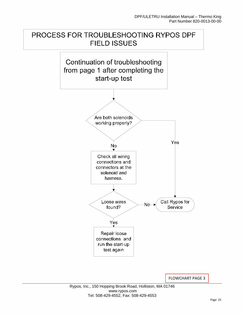
PROCESS FOR TROUBLESHOOTING RYPOS DPF FIELD ISSUES
Start Here
Isthe engine running?
Checkbattery voltage,
over 11V?
No
Yes
Charge Battery
No
Start engine and check alternator output voltage.
Change Battery
Checkbattery voltage,
over 11V?
No
YesIs the voltage above 13V?
Check alternator belt tension. Retighten and check voltage
again.
System OK
No
Is the voltage above 13V?
Yes
Yes
Go to page 2 and check the DPF system lights
Replace the Alternator.(Return to Rypos if supplied by
Rypos and is still under warranty)No
Run the ‘Start up and operation of DPF’ test in this installation manual
Yes
Are bothsolenoids working
and is the unit regenerating
properly?
Yes
Go to page 3 and continue
troubleshooting
No
Check starter circuit and refer to the TRU manual for
troubleshooting
FLOWCHART PAGE 1

DPF/ULETRU Installation Manual – Thermo King Part Number 820-0013-00-00
Rypos, Inc., 150 Hopping Brook Road, Holliston, MA 01746 www.rypos.com
Tel: 508-429-4552, Fax: 508-429-4553 Page 24
FLOWCHART PAGE 2
DPF/ULETRU Installation Manual – Thermo King Part Number 820-0013-00-00
Rypos, Inc., 150 Hopping Brook Road, Holliston, MA 01746 www.rypos.com
Tel: 508-429-4552, Fax: 508-429-4553 Page 25
FLOWCHART PAGE 3

DPF/ULETRU Installation Manual – Thermo King Part Number 820-0013-00-00
Rypos, Inc., 150 Hopping Brook Road, Holliston, MA 01746 www.rypos.com
Tel: 508-429-4552, Fax: 508-429-4553 Page 26
TRU DPF SERVICE PARTS LIST DPF/ULETRU THERMO KING
ITEM DESCRIPTION PART NUMBER
ULETRU FILTER CAN ASSEMBLY, TK 960‐0045‐00‐00 ECU ASSEMBLY, W/BRACKET 970‐0029‐00‐00 ECU 970‐0007‐00‐03 ALTERNATOR, 120 AMP BOSCH (AL9120N) 175‐0017‐00‐00 ALTERNATOR PULLEY, 2.625" DIA 775‐0005‐00‐00 ALTERNATOR BELT (THERMO KING) 780‐0004‐00‐00 ALTERNATOR BELT (OPTIBELT) 780‐0007‐00‐00 RAIN CAP 2.0" OD 559‐0003‐00‐00 EXHAUST PIPE W/DOC 559‐0012‐00‐00 CLAMP U‐STYLE 1.75" DIAMETER PIPE 598‐0003‐00‐00 CUTTING TEMPLATE, SHROUD 599‐0023‐00‐00 PRESSURE TRANSDUCER ASSEMBLY 950‐0018‐00‐00 IC PRESSURE TRANSDUCER EXTERNAL 161‐0004‐00‐00 FLEXIBLE TUBING 3/8" OD x 3/16" ID SILICONE 737‐0001‐00‐00 TUBE, 304 SS 1/4" OD 597‐0017‐00‐00 VENT COVER FOR EXTERNAL PRESSURE TRANSDUCER 785‐0001‐00‐00 COMPRESSION FITTING 598‐0002‐00‐00 WIRING ASSY, INDICATOR LIGHTS 968‐0011‐00‐03 GROUND WIRE FOR CUTOUT SOLENOID 968‐0034‐00‐00 EXTERNAL PRESSURE TRANSDUCER CABLE 968‐0045‐00‐00 ENGINE RUN SIGNAL CABLE 968‐0049‐00‐00 RUN SIGNAL WIRE, POWER SOLENOID TO ECU 968‐0064‐00‐00 WIRING ASSY, SOLENOID JUMPER WIRE 968‐0065‐00‐00 POWER CUTOUT SOLENOID ASSEMBLY/W BRACKET 950‐0009‐00‐00 MEGA FUSE HOLDER W/ COVER 158‐0006‐00‐00 FUSE 100 AMP 158‐0009‐00‐00 SOLENOID FOR CUTOUT KIT 200A‐COATED 551‐0011‐00‐01 RESISTOR ASSEMBLY 968‐0066‐00‐00
POWER SOLENOID TO FUSE WIRE 968‐0051‐00‐00

DPF/ULETRU Installation Manual – Thermo King Part Number 820-0013-00-00
Rypos, Inc., 150 Hopping Brook Road, Holliston, MA 01746 www.rypos.com
Tel: 508-429-4552, Fax: 508-429-4553 Page 27
ULETRU DPF WIRING DIAGRAM
DPF/ULETRU Installation Manual – Thermo King Part Number 820-0013-00-00
Rypos, Inc., 150 Hopping Brook Road, Holliston, MA 01746 www.rypos.com
Tel: 508-429-4552, Fax: 508-429-4553 Page 28
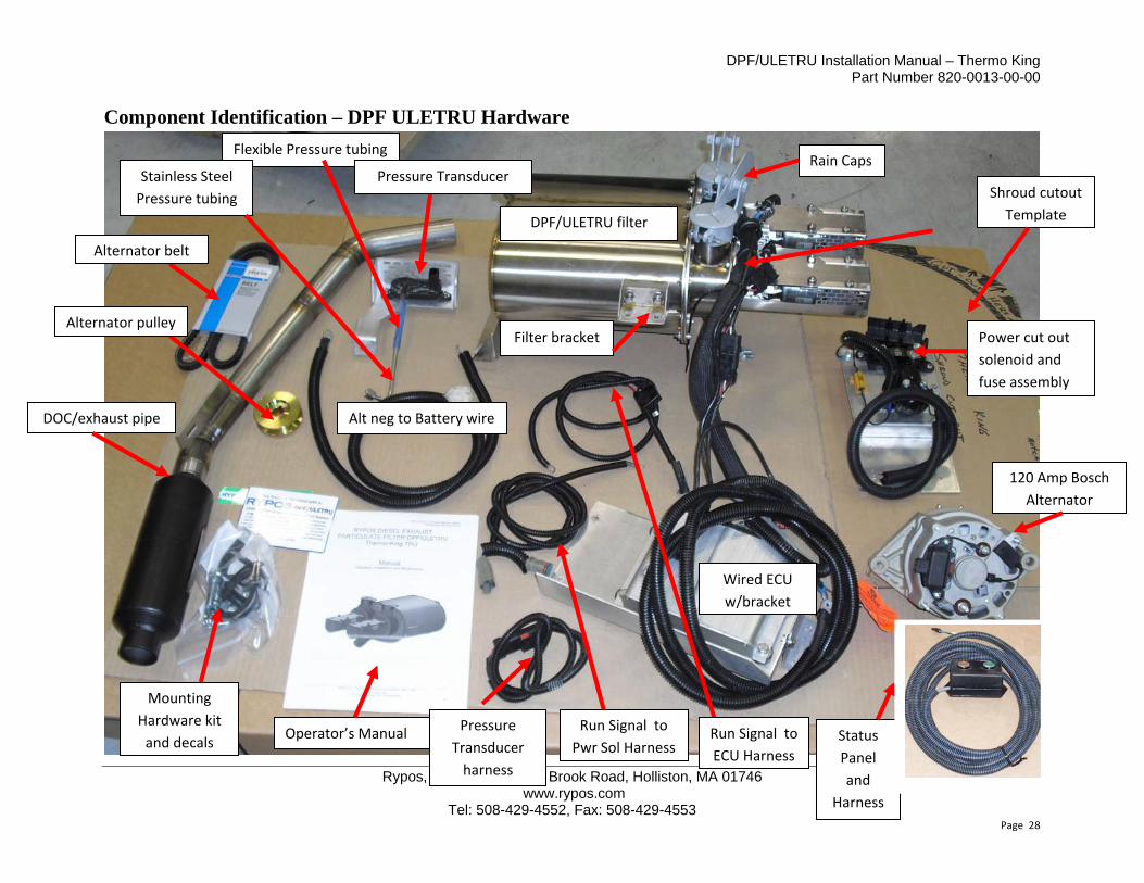
Component Identification – DPF ULETRU Hardware
Rain Caps
Operator’s Manual
Flexible Pressure tubing
Stainless Steel
Pressure tubing
Wired ECU
w/bracket
120 Amp Bosch
Alternator
Status
Panel
and
Harness
Shroud cutout
Template
Run Signal to
Pwr Sol Harness
Mounting
Hardware kit
and decals
DOC/exhaust pipe
Power cut out
solenoid and
fuse assembly
Alternator belt
Pressure Transducer
Alternator pulley
DPF/ULETRU filter
Alt neg to Battery wire
Run Signal to
ECU Harness
Pressure
Transducer
harness
Filter bracket

DPF/ULETRU Installation Manual – Thermo King Part Number 820-0013-00-00
Rypos, Inc., 150 Hopping Brook Road, Holliston, MA 01746 www.rypos.com
Tel: 508-429-4552, Fax: 508-429-4553 Page 29
Compatible Engine Models
Engine Manufacturer
Engine Model Year
Engine Manufacturer's Model Name Engine Family
Yanmar 2003 4TNE82‐ETK 3YDXL1.90D4N
Yanmar 2003 4TNE86‐ETK 3YDXL2.09D4N
Yanmar 2003 4TNE86‐ETK24 3YDXL2.09D4N
Yanmar 2003 4TNE86‐ETKH 3YDXL2.09D4N
Yanmar 2004 4TNV86TK‐VM 4YDXL2.09K4N
Yanmar 2004 TK486V 4YDXL2.09K4N
Yanmar 2004 TK486VB 4YDXL2.09K4N
Yanmar 2004 TK486VH 4YDXL2.09K4N
Yanmar 2005 4TNV86TK‐VM 5YDXL2.09K4N
Yanmar 2005 TK486V 5DXL2.09K4N
Yanmar 2005 TK486VB 5YDXL2.09K4N
Yanmar 2005 TK486VH 5YDXL2.09K4N
Yanmar 2006 4TNV86TK‐VM 6YDXL2.09K4N
Yanmar 2006 TK486V 6YDXL2.09K4N
Yanmar 2006 TK486VB 6YDXL2.09K4N
Yanmar 2006 TK486VH 6YDXL2.09K4N
Yanmar 2007 4TNV86TK‐VM 7YDXL2.09K4N
Yanmar 2007 TK486V 7YDXL2.09K4N
Yanmar 2007 TK486VB 7YDXL2.09K4N
Yanmar 2007 TK486VH 7YDXL2.09K4N
Yanmar 2007 4TNV86TK‐VM1 7YDXL2.09K4N
Yanmar 2008 4TNV86TK‐VM 8YDXL2.09K4N
Yanmar 2008 TK486V 8DXL2.09K4N
Yanmar 2008 TK486VB 8YDXL2.09K4N
Yanmar 2008 TK486VH 8DXL2.09K4N
Yanmar 2008 4TNV86TK‐VM1 8YDXL2.09M4N
Yanmar 2009 4TNV86TK‐VM 9YDXL2.09K4N
Yanmar 2009 TK486V 9DXL2.09K4N
Yanmar 2009 TK486VB 9YDXL2.09K4N
Yanmar 2009 TK486VH 9DXL2.09K4N
Yanmar 2009 4TNV86TK‐VM1 9YDXL2.09M4N
Yanmar 2010 4TNV86TK‐VM AYDXL2.09K4N
Yanmar 2010 TK486V ADXL2.09K4N
Yanmar 2010 TK486VB AYDXL2.09K4N
Yanmar 2010 TK486VH ADXL2.09K4N
Yanmar 2010 4TNV86TK‐VM1 AYDXL2.09M4N
Yanmar 2011 4TNV86TK‐VM BYDXL2.09K4N
Yanmar 2011 TK486V BDXL2.09K4N
Yanmar 2011 TK486VB BYDXL2.09K4N
Yanmar 2011 TK486VH BDXL2.09K4N
Yanmar 2011 4TNV86TK‐VM1 BYDXL2.09M4N
DPF/ULETRU Installation Manual – Thermo King Part Number 820-0013-00-00
Rypos, Inc., 150 Hopping Brook Road, Holliston, MA 01746 www.rypos.com
Tel: 508-429-4552, Fax: 508-429-4553 Page 30
Warranty Statement
YOUR WARRANTY RIGHTS AND OBLIGATIONS
Rypos, Inc. must warrant the diesel emission control system in the application for which it is sold or leased to be free from defects in design, materials, workmanship, or operation of the diesel emission control system which cause the diesel emission control system to fail to conform to the emission control performance level it was verified to, or to the requirements in the California Code of Regulations, Title 13, Sections 2700 to 2706, and 2710, for the periods of time listed below, provided there has been no abuse, neglect, or improper maintenance of your diesel emission control system, vehicle or equipment, as specified in the owner’s manuals. Where a warrantable condition exists, this warranty also covers the engine from damage caused by the diesel emission control system, subject to the same exclusions for abuse, neglect or improper maintenance of your vehicle or equipment. Please review your owner’s manual for other warranty information. Your diesel emission control system may include a core part (e.g., particulate filter, diesel oxidation catalyst, selective catalytic reduction converter) as well as hoses, connectors, a back pressure monitor (if applicable), and other emission-related assemblies. Where a warrantable condition exists, Rypos, Inc. will repair or replace your diesel emission control system at no cost to you including diagnosis, parts, and labor.
WARRANTY COVERAGE:
For a 25 to 50 horsepower engine used in a single temperature Thermo King or Carrier transport refrigeration unit application, the warranty period will be 4 years or 2600 hours, whichever occurs first. If any emission-related part of your diesel emission control system is defective in design, materials, workmanship, or operation of the diesel emission control system thus causing the diesel emission control system to fail to conform to the emission control performance level it was verified to, or to the requirements in the California Code of Regulations, Title 13, Sections 2700 to 2706, and 2710, within the warranty period, as defined above, Rypos, Inc. will repair or replace the diesel emission control system, including parts and labor.
In addition, Rypos, Inc. will replace or repair the engine components to the condition they were in prior to the failure, including parts and labor, for damage to the engine proximately caused by the verified diesel emission control strategy. This also includes those relevant diagnostic expenses in the case in which a warranty claim is valid. Rypos, Inc. may, at its option, instead pay the fair market value of the engine prior to the time the failure occurs.
OWNER’S WARRANTY RESPONSIBILITY
As the engine owner, you are responsible for performing the required maintenance described in your owner’s manual. Rypos, Inc. recommends that you retain all maintenance records and receipts for maintenance expenses for your vehicle, engine, or equipment, and diesel emission control system. If you do not keep your receipts or fail to perform all scheduled maintenance, Rypos, Inc. may have
DPF/ULETRU Installation Manual – Thermo King Part Number 820-0013-00-00
Rypos, Inc., 150 Hopping Brook Road, Holliston, MA 01746 www.rypos.com
Tel: 508-429-4552, Fax: 508-429-4553 Page 31
grounds to deny warranty coverage. You are responsible for presenting your vehicle, equipment, or engine, and diesel emission control system to a Rypos, Inc. dealer as soon as a problem is detected. The warranty repair or replacement should be completed in a reasonable amount of time, not to exceed 30 days. If a replacement is needed, this may be extended to 90 days should a replacement not be available, but must be performed as soon as a replacement becomes available.
If you have questions regarding your warranty rights and responsibilities, you should contact Rypos, Inc. at 1-508-429-4552 or the California Air Resources Board at 9528 Telstar Avenue, El Monte, California 91731, or (800) 363-7664, or electronic mail: [email protected].
THIS WARRANTY IS THE ONLY WARRANTY APPLICABLE TO RYPOS ULETRU SYSTEMS. RYPOS MAKES NO OTHER WARRANTIES, EXPRESS OR IMPLIED, INCLUDING ANY IMPLIED WARRANTY OF MERCHANTABILITY OR FITNESS FOR A PARTICULAR PURPOSE. RYPOS SHALL NOT BE LIABLE FOR ANY INCIDENTAL OR CONSEQUENTIAL DAMAGES EXCEPT AS OTHERWISE PROVIDED HEREIN.
DENIAL OF WARRANTY COVERAGE
1. Repairs due to accident, misuse, alteration, misapplication, storage damage, negligence or modification not authorized by Rypos, Inc. are not covered by this warranty.
2. The warranty does not cover repairs under the following conditions, without limitation: a) Failure of the engine owner or operator to heed the Rypos system’s warning lamps and take
timely action according to the Troubleshooting section of this Manual. b) Failure of the engine owner or operator to maintain the Rypos system according to the
maintenance requirements stated in this Manual. c) Failure of the engine owner or operator to maintain the engine according to the engine
manufacturer recommended requirements. 3. Except as otherwise provided above paragraph titled WARRANTY COVERAGE, Rypos, Inc. is
not responsible for repair of components and/or assemblies which are manufactured or supplied by another manufacturer. Such items may be covered by the manufacturer or supplier.
LIMITATION OF DAMAGES
The performance of repair or replacement of the Rypos ULETRU system or of TRU engine components is the Owner’s exclusive remedy under this warranty. Rypos does not authorize any person to assume or create for it any other obligation or liability in connection with the Rypos ULETRU. Except as expressly warranted in the above paragraph titled WARRANTY COVERAGE, Rypos is not responsible for incidental or consequential costs or expenses which the owner may incur as a result of a malfunction or failure covered by this warranty, including but not limited to loss of profits, loss of time, inconvenience, and other costs and expenses.
CARB Identification Number (IDN) Registration After installing the RYPOS DPF/ULETRU system, the TRU owner may apply for a CARB IDN at: www.arb.ca.gov/diesel/tru/tru.htm

DPF/ULETRU Installation Manual – Thermo King Part Number 820-0013-00-00
Rypos, Inc., 150 Hopping Brook Road, Holliston, MA 01746 www.rypos.com
Tel: 508-429-4552, Fax: 508-429-4553 Page 32
Pre-Installation Compatibility Assessment and Warranty Registration Form 1) Verify that the engine year and family is listed in the Compatible Engine Models Table
2) Inspect the TRU unit for oil leaks, general maintenance, signs of oil in exhaust, hrs on the oil and oil
filter, condition of air filter, color of smoke during steady state operation at both high and low speed)
3) Fill out ALL information below, sign statement, give one copy to the customer and send one copy
to Rypos (Warranty coverage for incomplete information will be the responsibility of the installer!)
TRU owner’s company name and address:________________________________________________
Contact name_____________________ phone:________________ E‐mail______________________
Installer’s name:_____________________ phone:_______________ E‐mail_____________________
Installation date:_____________ TRU readings: Switch on hours___________ Engine hours________
TRU model name: (SB210, SB300 etc.):_________________(CANNOT BE INSTALLED ON MULTI‐TEMP)
TRU serial number:_________________________________ Date in Service:______________
TRU engine serial number (From data label on engine and unit frame):_________________________
Rypos DPF/ULETRU serial number: U___ ___ ___ ___ Date of Manufacture___________________
Current ARB #_________________________ Bosch Alternator Serial number:___________________
Statement of Compatibility: “I have inspected the engine for signs of poor maintenance (oil leaks, oil filter over 1 year old, oil with more than recommended hrs on it, dirty air filter, worn belts, etc). I have looked at the exhaust soot for oil content, and I have observed the color of the exhaust both in high and low speed (No color should be visible in steady state operation) and I hereby affirm that the TRU listed above has met ALL of the above compatibility criteria for installation of DPF/ULETRU”
________ YES, ALL CRITERIA ACCEPTABLE ________ NO, THERE ARE ISSUES WITH THE UNIT THAT
MUST BE ADDRESSED BEFORE A DPF/ULETRU MAY BE INSTALLED (LIST ISSUES__________________)
Statement of Warranty: “I hereby warrant that the installation of the Rypos DPF/ULETRU is free
from defects in workmanship or materials which cause the diesel emission control system to fail to
conform to the emission control performance level it was verified to, or to the requirements in the
California Code of Regulations, Title 13, Sections 2700 to 2706. The warranty period and the extent
of the warranty coverage provided by me must be the same as the warranty provided by Rypos, Inc.,
and the same exclusions must apply”
SIGNED__________________________________________________ DATE_____________
Rypos Family Name for Verification: CA/RYP/2011/PM3+/N00/TR/DPF01 Rypos Copy
Scan/e‐mail to: [email protected], or fax to 508‐429‐4553