Ruud Value Series Ruud Achiever Value Series Package Gas ... · RKKN Series FORM NO. R22-868 REV. 4...
40
RKKN-B Standard Efficiency Series RKKN-C Standard Efficiency Series With ClearControl ™ (DDC) Nominal Sizes6 Ton [21.1 kW] ASHRAE 90.1-2010 Compliant Models “Proper sizing and installation of equipment is critical to achieve optimal performance. Ask your Contractor for details or visit www.energystar.gov.” Package Gas Electric RKKN Series FORM NO. R22-868 REV. 4 Rely on Ruud.™ Ruud Achiever ® Value Series Package Gas Electric Unit Ruud Achiever ® Value Series Package Gas Electric Unit
Transcript of Ruud Value Series Ruud Achiever Value Series Package Gas ... · RKKN Series FORM NO. R22-868 REV. 4...
RKKN-B Standard Efficiency SeriesRKKN-C Standard Efficiency SeriesWith ClearControl™ (DDC)
Nominal Sizes 6 Ton [21.1 kW]ASHRAE 90.1-2010 Compliant Models
“Proper sizing and installation of equipment is critical toachieve optimal performance. Ask your Contractor for detailsor visit www.energystar.gov.”
Package Gas ElectricRKKN Series
FORM NO. R22-868 REV. 4
Rely on Ruud.™
Ruud Achiever® Value Series Package Gas Electric UnitRuud Achiever® Value Series Package Gas Electric Unit
Table of ContentsRKKN Series
Rely on Ruud.™2
Unit Features & Benefits ..............................................................................3-5
Model Number Identification ............................................................................6
Selection Procedure........................................................................................7
Options ......................................................................................................8-9
General Data............................................................................................10-12
General Data Notes ......................................................................................13
Gross Systems Performance Data ..................................................................14
Indoor Airflow Performance............................................................................15
Electrical Data ..............................................................................................16
Dimensional Data ....................................................................................17-19
Accessories ............................................................................................20-30
Mechanical Specifications ........................................................................31-36
Limited Warranty ..........................................................................................37
TABLE OF CONTENTSTABLE OF CONTENTS
Rely on Ruud.™ 3
Unit Features & BenefitsRKKN Series
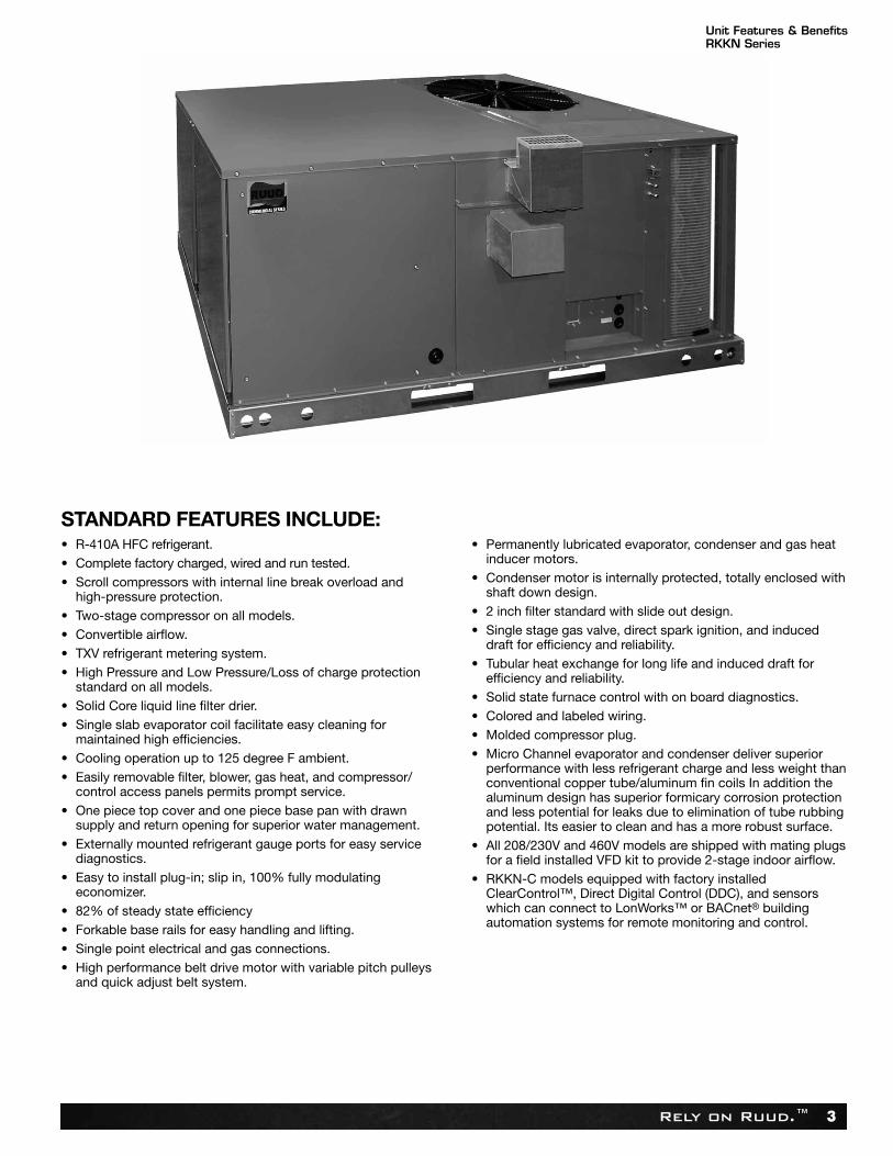
• R-410A HFC refrigerant.• Complete factory charged, wired and run tested.• Scroll compressors with internal line break overload and
high-pressure protection.• Two-stage compressor on all models.• Convertible airflow.• TXV refrigerant metering system.• High Pressure and Low Pressure/Loss of charge protection
standard on all models.• Solid Core liquid line filter drier.• Single slab evaporator coil facilitate easy cleaning for
maintained high efficiencies.• Cooling operation up to 125 degree F ambient.• Easily removable filter, blower, gas heat, and compressor/
control access panels permits prompt service.• One piece top cover and one piece base pan with drawn
supply and return opening for superior water management.• Externally mounted refrigerant gauge ports for easy service
diagnostics.• Easy to install plug-in; slip in, 100% fully modulating
economizer.• 82% of steady state efficiency• Forkable base rails for easy handling and lifting.• Single point electrical and gas connections.• High performance belt drive motor with variable pitch pulleys
and quick adjust belt system.
• Permanently lubricated evaporator, condenser and gas heatinducer motors.
• Condenser motor is internally protected, totally enclosed withshaft down design.
• 2 inch filter standard with slide out design.• Single stage gas valve, direct spark ignition, and induced
draft for efficiency and reliability.• Tubular heat exchange for long life and induced draft for
efficiency and reliability.• Solid state furnace control with on board diagnostics.• Colored and labeled wiring.• Molded compressor plug.• Micro Channel evaporator and condenser deliver superior
performance with less refrigerant charge and less weight thanconventional copper tube/aluminum fin coils In addition thealuminum design has superior formicary corrosion protectionand less potential for leaks due to elimination of tube rubbingpotential. Its easier to clean and has a more robust surface.
• All 208/230V and 460V models are shipped with mating plugsfor a field installed VFD kit to provide 2-stage indoor airflow.
• RKKN-C models equipped with factory installedClearControl™, Direct Digital Control (DDC), and sensorswhich can connect to LonWorks™ or BACnet® buildingautomation systems for remote monitoring and control.
STANDARD FEATURES INCLUDE:
Rely on Ruud.™4
Unit Features & BenefitsRKKN Series
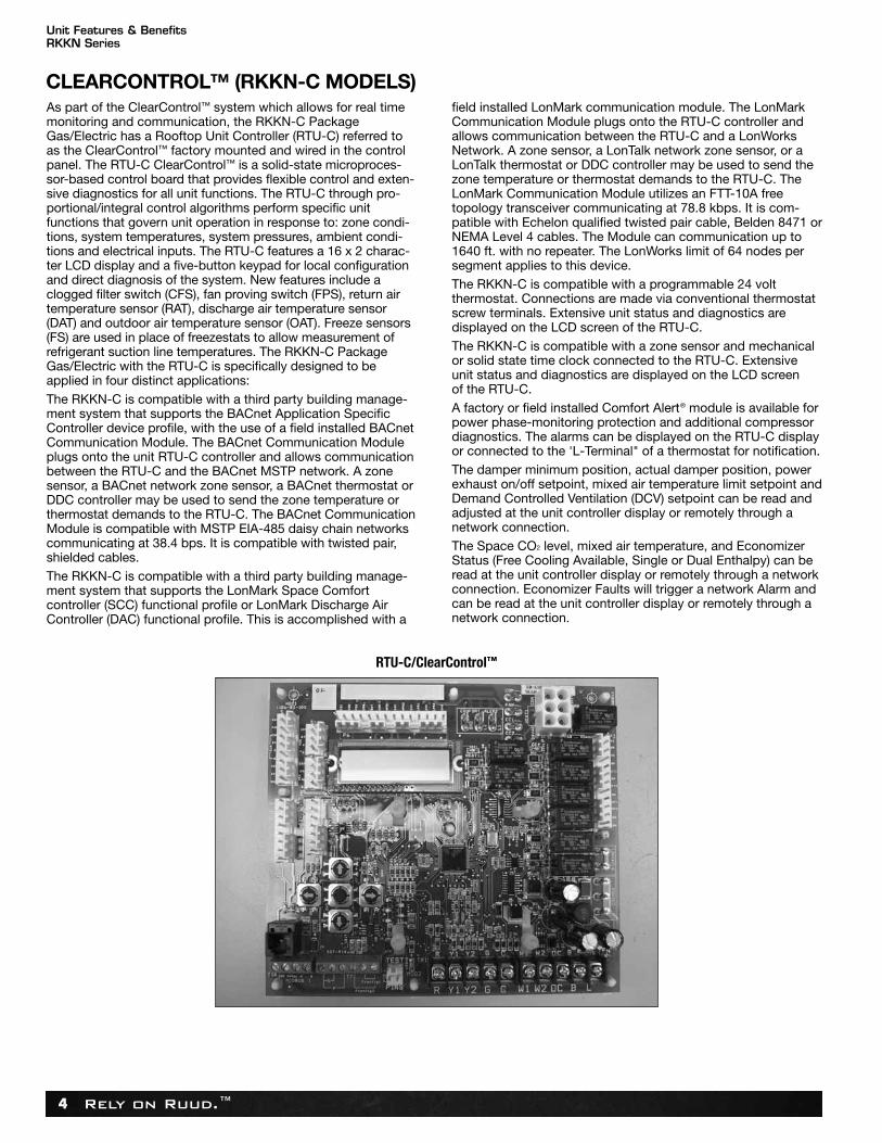
As part of the ClearControl™ system which allows for real timemonitoring and communication, the RKKN-C PackageGas/Electric has a Rooftop Unit Controller (RTU-C) referred toas the ClearControl™ factory mounted and wired in the controlpanel. The RTU-C ClearControl™ is a solid-state microproces-sor-based control board that provides flexible control and exten-sive diagnostics for all unit functions. The RTU-C through pro-portional/integral control algorithms perform specific unitfunctions that govern unit operation in response to: zone condi-tions, system temperatures, system pressures, ambient condi-tions and electrical inputs. The RTU-C features a 16 x 2 charac-ter LCD display and a five-button keypad for local configurationand direct diagnosis of the system. New features include aclogged filter switch (CFS), fan proving switch (FPS), return airtemperature sensor (RAT), discharge air temperature sensor(DAT) and outdoor air temperature sensor (OAT). Freeze sensors(FS) are used in place of freezestats to allow measurement ofrefrigerant suction line temperatures. The RKKN-C PackageGas/Electric with the RTU-C is specifically designed to beapplied in four distinct applications:The RKKN-C is compatible with a third party building manage-ment system that supports the BACnet Application SpecificController device profile, with the use of a field installed BACnetCommunication Module. The BACnet Communication Moduleplugs onto the unit RTU-C controller and allows communicationbetween the RTU-C and the BACnet MSTP network. A zonesensor, a BACnet network zone sensor, a BACnet thermostat orDDC controller may be used to send the zone temperature orthermostat demands to the RTU-C. The BACnet CommunicationModule is compatible with MSTP EIA-485 daisy chain networkscommunicating at 38.4 bps. It is compatible with twisted pair,shielded cables.The RKKN-C is compatible with a third party building manage -ment system that supports the LonMark Space Comfortcontroller (SCC) functional profile or LonMark Discharge AirController (DAC) functional profile. This is accomplished with a
field installed LonMark communication module. The LonMarkCommunication Module plugs onto the RTU-C controller andallows communication between the RTU-C and a LonWorksNetwork. A zone sensor, a LonTalk network zone sensor, or aLonTalk thermostat or DDC controller may be used to send thezone temperature or thermostat demands to the RTU-C. TheLonMark Communication Module utilizes an FTT-10A freetopology transceiver communicating at 78.8 kbps. It is com-patible with Echelon qualified twisted pair cable, Belden 8471 orNEMA Level 4 cables. The Module can communication up to1640 ft. with no repeater. The LonWorks limit of 64 nodes persegment applies to this device.The RKKN-C is compatible with a programmable 24 voltthermostat. Connections are made via conventional thermostatscrew terminals. Extensive unit status and diagnostics aredisplayed on the LCD screen of the RTU-C.The RKKN-C is compatible with a zone sensor and mechanicalor solid state time clock connected to the RTU-C. Extensiveunit status and diagnostics are displayed on the LCD screenof the RTU-C.A factory or field installed Comfort Alert® module is available forpower phase-monitoring protection and additional compressordiagnostics. The alarms can be displayed on the RTU-C displayor connected to the 'L-Terminal" of a thermostat for notification.The damper minimum position, actual damper position, powerexhaust on/off setpoint, mixed air temperature limit setpoint andDemand Controlled Ventilation (DCV) setpoint can be read andadjusted at the unit controller display or remotely through anetwork connection.The Space CO2 level, mixed air temperature, and EconomizerStatus (Free Cooling Available, Single or Dual Enthalpy) can beread at the unit controller display or remotely through a networkconnection. Economizer Faults will trigger a network Alarm andcan be read at the unit controller display or remotely through anetwork connection.
RTU-C/ClearControl™
CLEARCONTROL™ (RKKN-C MODELS)
Rely on Ruud.™ 5
Unit Features & BenefitsRKKN Series
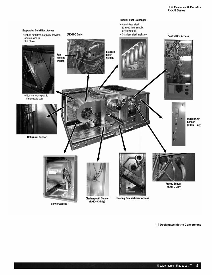
Evaporator Coil/Filter Access
• Return air filters, normally provided,are removed inthis photo.
(RKKN-C Only)
Tubular Heat Exchanger
• Aluminized steel(viewed from supplyair side panel.)
• Stainless steel available
Heating Compartment Access
Blower Access
Control Box Access
• Non-corrosive plasticcondensate pan
[ ] Designates Metric Conversions
Outdoor AirSensor(RKKN- Only)
Freeze Sensor(RKKN-C Only)
Discharge Air Sensor(RKKN-C Only)
Return Air Sensor
FanProvingSwitch
CloggedFilterSwitch
Rely on Ruud.™6
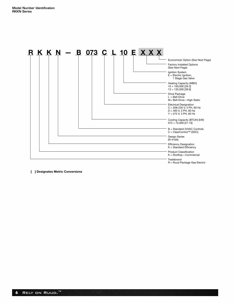
R K K N — B 073 C L 10 E X X X Economizer Option (See Next Page) Factory Installed Options (See Next Page) Ignition System E = Electric Ignition,
1 Stage Gas Valve Heating Capacity (MBH) 10 = 100,000 [29.3] 13 = 135,000 [39.6]
Drive Package L = Belt Drive M= Belt Drive—High Static
Electrical Designation C = 208-230 V, 3 PH, 60 Hz D = 460 V, 3 PH, 60 Hz Y = 575 V, 3 PH, 60 Hz
Cooling Capacity (BTUH) [kW] 073 = 72,000 [21.10]
B = Standard 24VAC ControlsC = ClearControl™ (DDC)
Design Series (R-410A)
Efficiency Designation K = Standard Efficiency
Product Classification K = Rooftop—Commercial Tradebrand R = Ruud Package Gas Electric
[ ] Designates Metric Conversions
Model Number IdentificationRKKN Series
Rely on Ruud.™ 7
1. Determine cooling and heating requirements at design conditions. Example: Power Supply ....................................208/230-3 Phase Total cooling capacity ........................61,000 BTUH [17.87 kW] Sensible cooling capacity ..................44,000 BTUH [12.89 kW] Heating capacity ................................96,000 BTUH [28.13 kW] Condenser entering air ......................95°F [35°C] Evaporator entering air ......................63°F [17°C] wb/76°F [24°C] db Indoor air flow ....................................2100 CFM [991 L/s] External static pressure ....................1.1 in wg Required efficiency ............................11.0 EER, 12.9 IEER
2. Select unit to meet cooling requirements.Since total cooling is within the range of 6 ton [21.10 kW] unit andrequires 11.0 EER/12.9 IEER efficiency level, enter cooling perfor-mance from the RKKN-B073 at 95°F [35°C] outdoor temperature,63°F [17°C] wb entering indoor air, and 2100 CFM [991 L/s]:
Total capacity ....................................65,000 BTUH [19.1 kW] Sensible capacity ..............................55,400 BTUH [16.2 kW] Power input........................................5.4 kW And also, at 76°F [24°C] db indoor entering air, and using the formula
at the bottom of the table: Sensible capacity ..............................48,008 BTUH [14.07 kW]
3. Select heating capacity of the unit. In the general data tables, note that the heating capacity of the 6 ton
[21.10 kW] model with the 135,000 input heater can deliver 109,400BTUH [32.03 kW], which is suitable for this application.
4. Determine blower speed and power to meet the systemrequirements.
At the given external static pressure of 1.1 in wg, the belt model mustbe selected. Enter the belt drive blower performance data at 2100CFM [991 L/s] and 1.1 in wg ESP:
RPM ........1130 Watts ......1060 Drive ........M
5. Calculate indoor blower BTUH heat effect. BTUH = Watts x 3.413 = 3618
6. Calculate net cooling capacities. Net total cooling = 65,000 – 3618 = 61,382 BTUH [17.98 kW] Net sensible cooling = 48,008 – 3618 = 44,390 BTUH [13.01 kW]
7. Select model RKKN-B073CM13E
[ ] Designates Metric Conversions
Selection Procedure RKKN Series
Rely on Ruud.™8
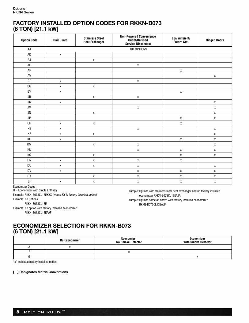
OptionsRKKN Series
Option Code Hail Guard Stainless SteelHeat Exchanger
Non-Powered ConvenienceOutlet/Unfused
Service Disconnect
Low Ambient/Freeze Stat Hinged Doors
AA NO OPTIONS
AD x
AJ x
AH x
AP x
AV x
BF x x
BG x x
BY x x
JB x x
JK x x
JM x x
JN x x
JP x x
CR x x x
KE x x x
KF x x x
KG x x x
KM x x x
KN x x x
KQ x x x
DN x x x x
DU x x x x
DV x x x x
DX x x x x
EF x x x x x
FACTORY INSTALLED OPTION CODES FOR RKKN-B073 (6 TON) [21.1 kW]
Economizer CodesH = Economizer with Single EnthalpyExample: RKKN-B073CL13EXXX (where XX is factory installed option)Example: No Options
RKKN-B073CL13EExample: No option with factory installed economizer
RKKN-B073CL13EAAF
Example: Options with stainless steel heat exchanger and no factory installed economizer RKKN-B073CL13EAJA
Example: Options same as above with factory installed economizerRKKN-B073CL13EAJF
No Economizer EconomizerNo Smoke Detector
A xF xG
EconomizerWith Smoke Detector
x
ECONOMIZER SELECTION FOR RKKN-B073(6 TON) [21.1 kW]
“x” indicates factory installed option.
[ ] Designates Metric Conversions
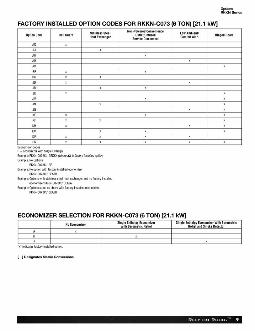
OptionsRKKN Series
Rely on Ruud.™ 9
Option Code Hail Guard Stainless SteelHeat Exchanger
Non-Powered ConvenienceOutlet/Unfused
Service Disconnect
Low Ambient/Comfort Alert Hinged Doors
AD x
AJ x
AH x
AR x
AV x
BF x x
BG x x
JD x x
JB x x
JK x x
JM x x
JN x x
JQ x x
KE x x x
KF x x x
KH x x x
KM x x x
DP x x x x
EG x x x x x
FACTORY INSTALLED OPTION CODES FOR RKKN-C073 (6 TON) [21.1 kW]
Economizer CodesH = Economizer with Single EnthalpyExample: RKKN-C073CL13EXXX (where XX is factory installed option)Example: No Options
RKKN-C073CL13EExample: No option with factory installed economizer
RKKN-C073CL13EAAH Example: Options with stainless steel heat exchanger and no factory installed
economizer RKKN-C073CL13EAJAExample: Options same as above with factory installed economizer
RKKN-C073CL13EAJH
No Economizer Single Enthalpy EconomizerWith Barometric Relief
A xH xJ
Single Enthalpy Economizer With BarometricRelief and Smoke Detector
x
ECONOMIZER SELECTION FOR RKKN-C073 (6 TON) [21.1 kW]
“x” indicates factory installed option.
[ ] Designates Metric Conversions
Rely on Ruud.™10
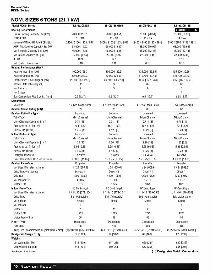
General DataRKKN Series
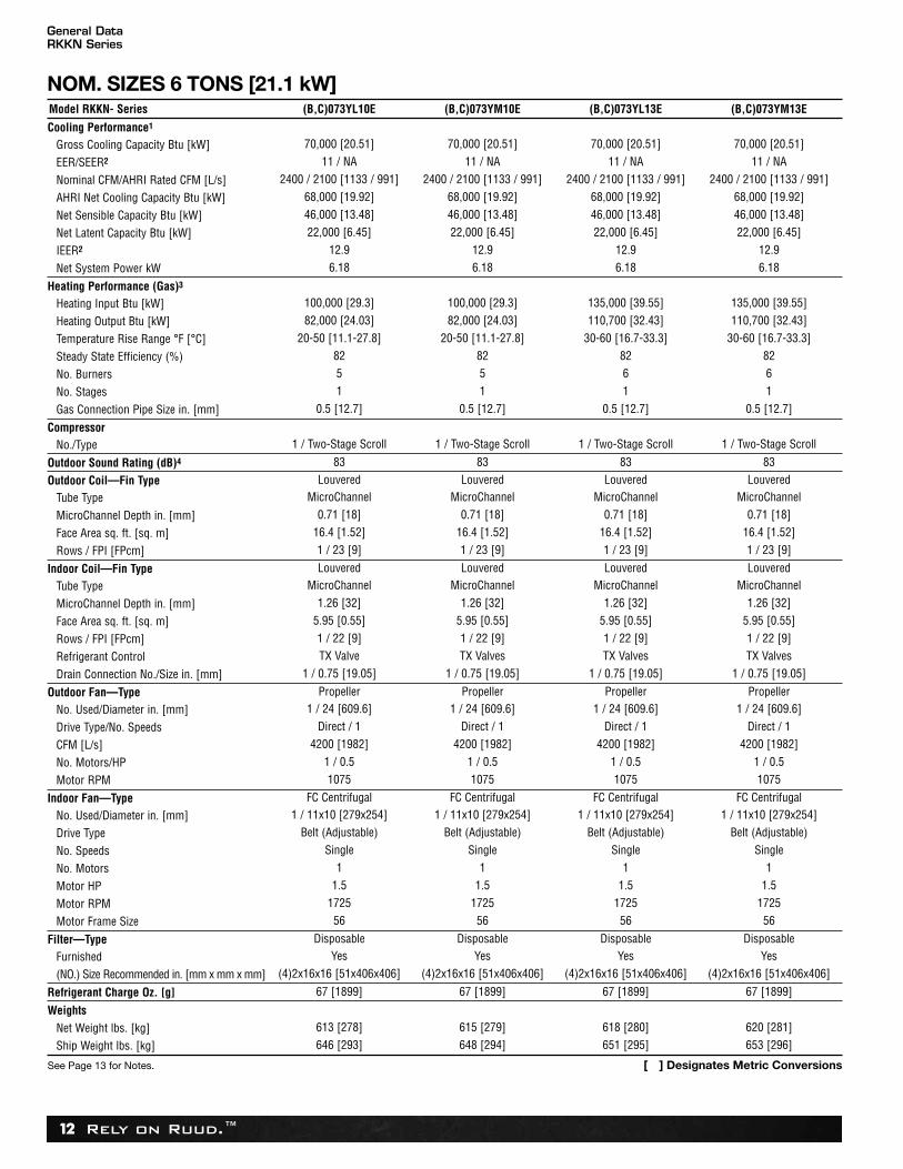
Model RKKN- Series (B,C)073CL10E (B,C)073CM10E (B,C)073CL13E (B,C)073CM13E
Cooling Performance1 CONTINUEDGross Cooling Capacity Btu [kW] 70,000 [20.51] 70,000 [20.51] 70,000 [20.51] 70,000 [20.51]EER/SEER2 11 / NA 11 / NA 11 / NA 11 / NANominal CFM/AHRI Rated CFM [L/s] 2400 / 2100 [1133 / 991] 2400 / 2100 [1133 / 991] 2400 / 2100 [1133 / 991] 2400 / 2100 [1133 / 991]AHRI Net Cooling Capacity Btu [kW] 68,000 [19.92] 68,000 [19.92] 68,000 [19.92] 68,000 [19.92]Net Sensible Capacity Btu [kW] 46,000 [13.48] 46,000 [13.48] 46,000 [13.48] 46,000 [13.48]Net Latent Capacity Btu [kW] 22,000 [6.45] 22,000 [6.45] 22,000 [6.45] 22,000 [6.45]IEER2 12.9 12.9 12.9 12.9Net System Power kW 6.18 6.18 6.18 6.18
Heating Performance (Gas)3
Heating Input Btu [kW] 100,000 [29.3] 100,000 [29.3] 135,000 [39.55] 135,000 [39.55]Heating Output Btu [kW] 82,000 [24.03] 82,000 [24.03] 110,700 [32.43] 110,700 [32.43]Temperature Rise Range °F [°C] 20-50 [11.1-27.8] 20-50 [11.1-27.8] 30-60 [16.7-33.3] 30-60 [16.7-33.3]Steady State Efficiency (%) 82 82 82 82No. Burners 5 5 6 6No. Stages 1 1 1 1Gas Connection Pipe Size in. [mm] 0.5 [12.7] 0.5 [12.7] 0.5 [12.7] 0.5 [12.7]
CompressorNo./Type 1 / Two-Stage Scroll 1 / Two-Stage Scroll 1 / Two-Stage Scroll 1 / Two-Stage Scroll
Outdoor Sound Rating (dB)4 83 83 83 83Outdoor Coil—Fin Type Louvered Louvered Louvered Louvered
Tube Type MicroChannel MicroChannel MicroChannel MicroChannelMicroChannel Depth in. [mm] 0.71 [18] 0.71 [18] 0.71 [18] 0.71 [18]Face Area sq. ft. [sq. m] 16.4 [1.52] 16.4 [1.52] 16.4 [1.52] 16.4 [1.52]Rows / FPI [FPcm] 1 / 23 [9] 1 / 23 [9] 1 / 23 [9] 1 / 23 [9]
Indoor Coil—Fin Type Louvered Louvered Louvered LouveredTube Type MicroChannel MicroChannel MicroChannel MicroChannelMicroChannel Depth in. [mm] 1.26 [32] 1.26 [32] 1.26 [32] 1.26 [32]Face Area sq. ft. [sq. m] 5.95 [0.55] 5.95 [0.55] 5.95 [0.55] 5.95 [0.55]Rows / FPI [FPcm] 1 / 22 [9] 1 / 22 [9] 1 / 20 [8] 1 / 22 [9]Refrigerant Control TX Valve TX Valve TX Valve TX ValveDrain Connection No./Size in. [mm] 1 / 0.75 [19.05] 1 / 0.75 [19.05] 1 / 0.75 [19.05] 1 / 0.75 [19.05]
Outdoor Fan—Type Propeller Propeller Propeller PropellerNo. Used/Diameter in. [mm] 1 / 24 [609.6] 1 / 24 [609.6] 1 / 24 [609.6] 1 / 24 [609.6]Drive Type/No. Speeds Direct / 1 Direct / 1 Direct / 1 Direct / 1CFM [L/s] 4200 [1982] 4200 [1982] 4200 [1982] 4200 [1982]No. Motors/HP 1 / 0.5 1 / 0.5 1 / 0.5 1 / 0.5Motor RPM 1075 1075 1075 1075
Indoor Fan—Type FC Centrifugal FC Centrifugal FC Centrifugal FC CentrifugalNo. Used/Diameter in. [mm] 1 / 11x10 [279x254] 1 / 11x10 [279x254] 1 / 11x10 [279x254] 1 / 11x10 [279x254]Drive Type Belt (Adjustable) Belt (Adjustable) Belt (Adjustable) Belt (Adjustable)No. Speeds Single Single Single SingleNo. Motors 1 1 1 1Motor HP 2 2 2 2Motor RPM 1725 1725 1725 1725Motor Frame Size 56 56 56 56
Filter—Type Disposable Disposable Disposable DisposableFurnished Yes Yes Yes Yes(NO.) Size Recommended in. [mm x mm x mm] (4)2x16x16 [51x406x406] (4)2x16x16 [51x406x406] (4)2x16x16 [51x406x406] (4)2x16x16 [51x406x406]
Refrigerant Charge Oz. [g] 67 [1899] 67 [1899] 67 [1899] 67 [1899]
Weights
Net Weight lbs. [kg] 615 [279] 617 [280] 620 [281] 622 [282]Ship Weight lbs. [kg] 648 [294] 650 [295] 653 [296] 655 [297]
NOM. SIZES 6 TONS [21.1 kW]
See Page 13 for Notes. [ ] Designates Metric Conversions
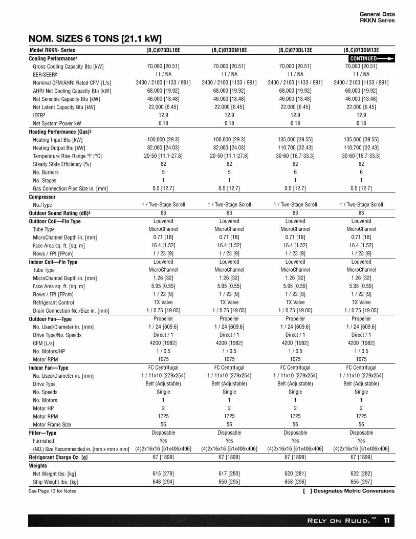
Rely on Ruud.™ 11
Model RKKN- Series (B,C)073DL10E (B,C)073DM10E (B,C)073DL13E (B,C)073DM13E
Cooling Performance1 CONTINUEDGross Cooling Capacity Btu [kW] 70,000 [20.51] 70,000 [20.51] 70,000 [20.51] 70,000 [20.51]
EER/SEER2 11 / NA 11 / NA 11 / NA 11 / NA
Nominal CFM/AHRI Rated CFM [L/s] 2400 / 2100 [1133 / 991] 2400 / 2100 [1133 / 991] 2400 / 2100 [1133 / 991] 2400 / 2100 [1133 / 991]
AHRI Net Cooling Capacity Btu [kW] 68,000 [19.92] 68,000 [19.92] 68,000 [19.92] 68,000 [19.92]
Net Sensible Capacity Btu [kW] 46,000 [13.48] 46,000 [13.48] 46,000 [13.48] 46,000 [13.48]
Net Latent Capacity Btu [kW] 22,000 [6.45] 22,000 [6.45] 22,000 [6.45] 22,000 [6.45]
IEER2 12.9 12.9 12.9 12.9
Net System Power kW 6.18 6.18 6.18 6.18
Heating Performance (Gas)3
Heating Input Btu [kW] 100,000 [29.3] 100,000 [29.3] 135,000 [39.55] 135,000 [39.55]
Heating Output Btu [kW] 82,000 [24.03] 82,000 [24.03] 110,700 [32.43] 110,700 [32.43]
Temperature Rise Range °F [°C] 20-50 [11.1-27.8] 20-50 [11.1-27.8] 30-60 [16.7-33.3] 30-60 [16.7-33.3]
Steady State Efficiency (%) 82 82 82 82
No. Burners 5 5 6 6
No. Stages 1 1 1 1
Gas Connection Pipe Size in. [mm] 0.5 [12.7] 0.5 [12.7] 0.5 [12.7] 0.5 [12.7]
CompressorNo./Type 1 / Two-Stage Scroll 1 / Two-Stage Scroll 1 / Two-Stage Scroll 1 / Two-Stage Scroll
Outdoor Sound Rating (dB)4 83 83 83 83
Outdoor Coil—Fin Type Louvered Louvered Louvered Louvered
Tube Type MicroChannel MicroChannel MicroChannel MicroChannel
MicroChannel Depth in. [mm] 0.71 [18] 0.71 [18] 0.71 [18] 0.71 [18]
Face Area sq. ft. [sq. m] 16.4 [1.52] 16.4 [1.52] 16.4 [1.52] 16.4 [1.52]
Rows / FPI [FPcm] 1 / 23 [9] 1 / 23 [9] 1 / 23 [9] 1 / 23 [9]
Indoor Coil—Fin Type Louvered Louvered Louvered Louvered
Tube Type MicroChannel MicroChannel MicroChannel MicroChannel
MicroChannel Depth in. [mm] 1.26 [32] 1.26 [32] 1.26 [32] 1.26 [32]
Face Area sq. ft. [sq. m] 5.95 [0.55] 5.95 [0.55] 5.95 [0.55] 5.95 [0.55]
Rows / FPI [FPcm] 1 / 22 [9] 1 / 22 [9] 1 / 22 [9] 1 / 22 [9]
Refrigerant Control TX Valve TX Valve TX Valve TX Valve
Drain Connection No./Size in. [mm] 1 / 0.75 [19.05] 1 / 0.75 [19.05] 1 / 0.75 [19.05] 1 / 0.75 [19.05]
Outdoor Fan—Type Propeller Propeller Propeller Propeller
No. Used/Diameter in. [mm] 1 / 24 [609.6] 1 / 24 [609.6] 1 / 24 [609.6] 1 / 24 [609.6]
Drive Type/No. Speeds Direct / 1 Direct / 1 Direct / 1 Direct / 1
CFM [L/s] 4200 [1982] 4200 [1982] 4200 [1982] 4200 [1982]
No. Motors/HP 1 / 0.5 1 / 0.5 1 / 0.5 1 / 0.5
Motor RPM 1075 1075 1075 1075
Indoor Fan—Type FC Centrifugal FC Centrifugal FC Centrifugal FC Centrifugal
No. Used/Diameter in. [mm] 1 / 11x10 [279x254] 1 / 11x10 [279x254] 1 / 11x10 [279x254] 1 / 11x10 [279x254]
Drive Type Belt (Adjustable) Belt (Adjustable) Belt (Adjustable) Belt (Adjustable)
No. Speeds Single Single Single Single
No. Motors 1 1 1 1
Motor HP 2 2 2 2
Motor RPM 1725 1725 1725 1725
Motor Frame Size 56 56 56 56
Filter—Type Disposable Disposable Disposable Disposable
Furnished Yes Yes Yes Yes
(NO.) Size Recommended in. [mm x mm x mm] (4)2x16x16 [51x406x406] (4)2x16x16 [51x406x406] (4)2x16x16 [51x406x406] (4)2x16x16 [51x406x406]
Refrigerant Charge Oz. [g] 67 [1899] 67 [1899] 67 [1899] 67 [1899]
Weights
Net Weight lbs. [kg] 615 [279] 617 [280] 620 [281] 622 [282]
Ship Weight lbs. [kg] 648 [294] 650 [295] 653 [296] 655 [297]
NOM. SIZES 6 TONS [21.1 kW]
See Page 13 for Notes. [ ] Designates Metric Conversions
General DataRKKN Series
Rely on Ruud.™12
NOM. SIZES 6 TONS [21.1 kW]Model RKKN- Series (B,C)073YL10E (B,C)073YM10E (B,C)073YL13E (B,C)073YM13E
Cooling Performance1
Gross Cooling Capacity Btu [kW] 70,000 [20.51] 70,000 [20.51] 70,000 [20.51] 70,000 [20.51]
EER/SEER2 11 / NA 11 / NA 11 / NA 11 / NA
Nominal CFM/AHRI Rated CFM [L/s] 2400 / 2100 [1133 / 991] 2400 / 2100 [1133 / 991] 2400 / 2100 [1133 / 991] 2400 / 2100 [1133 / 991]
AHRI Net Cooling Capacity Btu [kW] 68,000 [19.92] 68,000 [19.92] 68,000 [19.92] 68,000 [19.92]
Net Sensible Capacity Btu [kW] 46,000 [13.48] 46,000 [13.48] 46,000 [13.48] 46,000 [13.48]
Net Latent Capacity Btu [kW] 22,000 [6.45] 22,000 [6.45] 22,000 [6.45] 22,000 [6.45]
IEER2 12.9 12.9 12.9 12.9
Net System Power kW 6.18 6.18 6.18 6.18
Heating Performance (Gas)3
Heating Input Btu [kW] 100,000 [29.3] 100,000 [29.3] 135,000 [39.55] 135,000 [39.55]
Heating Output Btu [kW] 82,000 [24.03] 82,000 [24.03] 110,700 [32.43] 110,700 [32.43]
Temperature Rise Range °F [°C] 20-50 [11.1-27.8] 20-50 [11.1-27.8] 30-60 [16.7-33.3] 30-60 [16.7-33.3]
Steady State Efficiency (%) 82 82 82 82
No. Burners 5 5 6 6
No. Stages 1 1 1 1
Gas Connection Pipe Size in. [mm] 0.5 [12.7] 0.5 [12.7] 0.5 [12.7] 0.5 [12.7]
CompressorNo./Type 1 / Two-Stage Scroll 1 / Two-Stage Scroll 1 / Two-Stage Scroll 1 / Two-Stage Scroll
Outdoor Sound Rating (dB)4 83 83 83 83
Outdoor Coil—Fin Type Louvered Louvered Louvered Louvered
Tube Type MicroChannel MicroChannel MicroChannel MicroChannel
MicroChannel Depth in. [mm] 0.71 [18] 0.71 [18] 0.71 [18] 0.71 [18]
Face Area sq. ft. [sq. m] 16.4 [1.52] 16.4 [1.52] 16.4 [1.52] 16.4 [1.52]
Rows / FPI [FPcm] 1 / 23 [9] 1 / 23 [9] 1 / 23 [9] 1 / 23 [9]
Indoor Coil—Fin Type Louvered Louvered Louvered Louvered
Tube Type MicroChannel MicroChannel MicroChannel MicroChannel
MicroChannel Depth in. [mm] 1.26 [32] 1.26 [32] 1.26 [32] 1.26 [32]
Face Area sq. ft. [sq. m] 5.95 [0.55] 5.95 [0.55] 5.95 [0.55] 5.95 [0.55]
Rows / FPI [FPcm] 1 / 22 [9] 1 / 22 [9] 1 / 22 [9] 1 / 22 [9]
Refrigerant Control TX Valve TX Valves TX Valves TX Valves
Drain Connection No./Size in. [mm] 1 / 0.75 [19.05] 1 / 0.75 [19.05] 1 / 0.75 [19.05] 1 / 0.75 [19.05]
Outdoor Fan—Type Propeller Propeller Propeller Propeller
No. Used/Diameter in. [mm] 1 / 24 [609.6] 1 / 24 [609.6] 1 / 24 [609.6] 1 / 24 [609.6]
Drive Type/No. Speeds Direct / 1 Direct / 1 Direct / 1 Direct / 1
CFM [L/s] 4200 [1982] 4200 [1982] 4200 [1982] 4200 [1982]
No. Motors/HP 1 / 0.5 1 / 0.5 1 / 0.5 1 / 0.5
Motor RPM 1075 1075 1075 1075
Indoor Fan—Type FC Centrifugal FC Centrifugal FC Centrifugal FC Centrifugal
No. Used/Diameter in. [mm] 1 / 11x10 [279x254] 1 / 11x10 [279x254] 1 / 11x10 [279x254] 1 / 11x10 [279x254]
Drive Type Belt (Adjustable) Belt (Adjustable) Belt (Adjustable) Belt (Adjustable)
No. Speeds Single Single Single Single
No. Motors 1 1 1 1
Motor HP 1.5 1.5 1.5 1.5
Motor RPM 1725 1725 1725 1725
Motor Frame Size 56 56 56 56
Filter—Type Disposable Disposable Disposable Disposable
Furnished Yes Yes Yes Yes
(NO.) Size Recommended in. [mm x mm x mm] (4)2x16x16 [51x406x406] (4)2x16x16 [51x406x406] (4)2x16x16 [51x406x406] (4)2x16x16 [51x406x406]
Refrigerant Charge Oz. [g] 67 [1899] 67 [1899] 67 [1899] 67 [1899]
Weights
Net Weight lbs. [kg] 613 [278] 615 [279] 618 [280] 620 [281]
Ship Weight lbs. [kg] 646 [293] 648 [294] 651 [295] 653 [296]
General DataRKKN Series
See Page 13 for Notes. [ ] Designates Metric Conversions
Rely on Ruud.™ 13
General Data NotesRKKN Series
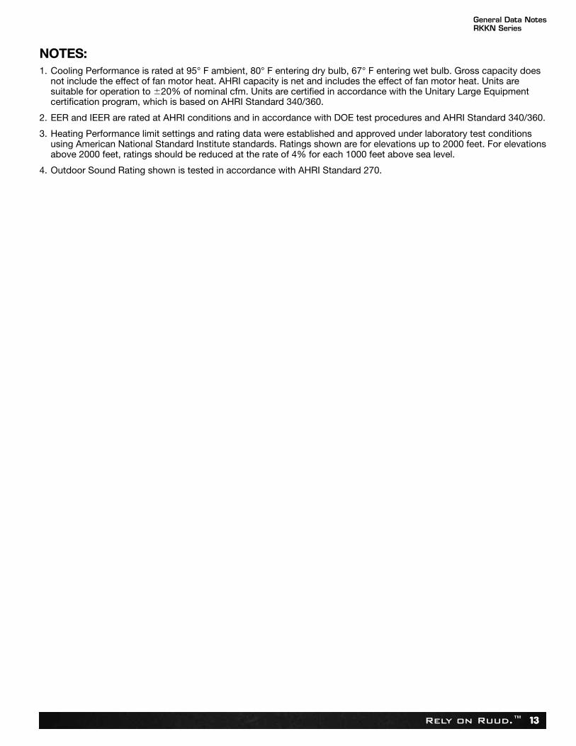
NOTES:1. Cooling Performance is rated at 95° F ambient, 80° F entering dry bulb, 67° F entering wet bulb. Gross capacity does
not include the effect of fan motor heat. AHRI capacity is net and includes the effect of fan motor heat. Units aresuitable for operation to �20% of nominal cfm. Units are certified in accordance with the Unitary Large Equipmentcertification program, which is based on AHRI Standard 340/360.
2. EER and IEER are rated at AHRI conditions and in accordance with DOE test procedures and AHRI Standard 340/360.
3. Heating Performance limit settings and rating data were established and approved under laboratory test conditionsusing American National Standard Institute standards. Ratings shown are for elevations up to 2000 feet. For elevationsabove 2000 feet, ratings should be reduced at the rate of 4% for each 1000 feet above sea level.
4. Outdoor Sound Rating shown is tested in accordance with AHRI Standard 270.
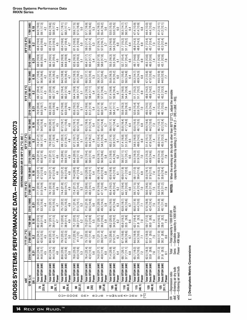
Rely on Ruud.™14
GR
OS
S S
YS
TEM
S P
ER
FOR
MA
NC
E D
ATA
—R
KK
N-B
073/
RK
KN
-C07
3EN
TER
ING
IND
OO
R A
IR @
80°
F [2
6.7°
C] d
bE ➀
wbE
71°F
[21.
7°C]
67°F
[19.
4°C]
63°F
[17.
2°C]
61°F
[16.
1°C]
59°F
[15.
0°C]
CFM
[L/s
]23
10 [1
090]
2100
[991
]17
80 [8
40]
2310
[109
0]21
00 [9
91]
1780
[840
]23
10 [1
090]
2100
[991
]17
80 [8
40]
2310
[109
0]21
00 [9
91]
1780
[840
]23
10 [1
090]
2100
[991
]17
80 [8
40]
DR
➀0.
210.
20.
180.
210.
20.
180.
210.
20.
180.
210.
20.
180.
210.
20.
18
O U T D O O R D R Y B U L B T E M P E R A T U R E °F [°C
]
75[2
3.9]
Tota
l BTU
H [k
W]
Sens
BTU
H [k
W]
Pow
er
84.0
[24.
6]44
.8 [1
3.1]
4.5
82.5
[24.
2]42
.8 [1
2.5]
4.5
80.2
[23.
5]39
.8 [1
1.6]
4.4
79.1
[23.
2]53
.3 [1
5.6]
4.4
77.7
[22.
8]51
.0 [1
4.9]
4.4
75.5
[22.
1]47
.3 [1
3.9]
4.3
73.8
[21.
6]60
.8 [1
7.8]
4.3
72.4
[21.
2]58
.1 [1
7.0]
4.3
70.4
[20.
6]54
.0 [1
5.8]
4.3
70.9
[20.
8]64
.0 [1
8.7]
4.3
69.7
[20.
4]61
.1 [1
7.9]
4.3
67.7
[19.
8]56
.8 [1
6.6]
4.2
68.0
[19.
9]66
.6 [1
9.5]
4.3
66.8
[19.
6]63
.6 [1
8.6]
4.2
64.9
[19.
0]59
.1 [1
7.3]
4.2
80[2
6.7]
Tota
l BTU
H [k
W]
Sens
BTU
H [k
W]
Pow
er
82.4
[24.
1]44
.4 [1
3.0]
4.8
80.9
[23.
7]42
.4 [1
2.4]
4.7
78.7
[23.
1]39
.4 [1
1.5]
4.7
77.5
[22.
7]52
.9 [1
5.5]
4.7
76.1
[22.
3]50
.6 [1
4.8]
4.6
74.0
[21.
7]47
.0 [1
3.8]
4.6
72.2
[21.
2]60
.4 [1
7.7]
4.6
70.9
[20.
8]57
.7 [1
6.9]
4.6
68.9
[20.
2]53
.6 [1
5.7]
4.5
69.3
[20.
3]63
.6 [1
8.6]
4.6
68.1
[20.
0]60
.7 [1
7.8]
4.5
66.2
[19.
4]56
.4 [1
6.5]
4.5
66.4
[19.
5]66
.2 [1
9.4]
4.5
65.2
[19.
1]63
.3 [1
8.5]
4.5
63.4
[18.
6]58
.8 [1
7.2]
4.4
85[2
9.4]
Tota
l BTU
H [k
W]
Sens
BTU
H [k
W]
Pow
er
80.6
[23.
6]43
.8 [1
2.8]
5.0
79.2
[23.
2]41
.9 [1
2.3]
5.0
77.0
[22.
6]38
.9 [1
1.4]
4.9
75.7
[22.
2]52
.3 [1
5.3]
4.9
74.4
[21.
8]50
.0 [1
4.7]
4.9
72.3
[21.
2]46
.5 [1
3.6]
4.8
70.4
[20.
6]59
.8 [1
7.5]
4.9
69.1
[20.
3]57
.2 [1
6.7]
4.8
67.2
[19.
7]53
.1 [1
5.6]
4.8
67.6
[19.
8]63
.0 [1
8.5]
4.8
66.3
[19.
4]60
.2 [1
7.6]
4.8
64.5
[18.
9]55
.9 [1
6.4]
4.7
64.6
[18.
9]64
.6 [1
8.9]
4.8
63.4
[18.
6]62
.7 [1
8.4]
4.7
61.7
[18.
1]58
.2 [1
7.1]
4.7
90[3
2.2]
Tota
l BTU
H [k
W]
Sens
BTU
H [k
W]
Pow
er
78.6
[23.
0]43
.0 [1
2.6]
5.3
77.2
[22.
6]41
.1 [1
2]5.
3
75.1
[22.
0]38
.2 [1
1.2]
5.2
73.7
[21.
6]51
.5 [1
5.1]
5.2
72.4
[21.
2]49
.2 [1
4.4]
5.2
70.4
[20.
6]45
.7 [1
3.4]
5.1
68.4
[20.
0]59
.0 [1
7.3]
5.2
67.2
[19.
7]56
.4 [1
6.5]
5.1
65.3
[19.
1]52
.4 [1
5.3]
5
65.6
[19.
2]62
.2 [1
8.2]
5.1
64.4
[18.
9]59
.4 [1
7.4]
5.1
62.6
[18.
3]55
.2 [1
6.2]
5.0
62.6
[18.
3]62
.6 [1
8.3]
5.1
61.5
[18.
0]61
.5 [1
8.0]
5.0
59.8
[17.
5]57
.5 [1
6.9]
5.0
95 [35]
Tota
l BTU
H [k
W]
Sens
BTU
H [k
W]
Pow
er
76.4
[22.
4]42
.0 [1
2.3]
5.6
75.1
[22.
0]40
.1 [1
1.8]
5.6
73.0
[21.
4]37
.3 [1
0.9]
5.5
71.6
[21.
0]50
.5 [1
4.8]
5.6
70.3
[20.
6]48
.3 [1
4.1]
5.5
68.3
[20.
0]44
.8 [1
3.1]
5.4
66.2
[19.
4]58
.0 [1
7.0]
5.5
65.0
[19.
1]55
.4 [1
6.2]
5.4
63.2
[18.
5]51
.5 [1
5.1]
5.4
63.4
[18.
6]61
.2 [1
7.9]
5.4
62.3
[18.
2]58
.4 [1
7.1]
5.4
60.5
[17.
7]54
.3 [1
5.9]
5.3
60.4
[17.
7]60
.4 [1
7.7]
5.4
59.3
[17.
4]59
.3 [1
7.4]
5.3
57.7
[16.
9]56
.6 [1
6.6]
5.3
100
[37.
8]
Tota
l BTU
H [k
W]
Sens
BTU
H [k
W]
Pow
er
74.0
[21.
7]40
.8 [1
1.9]
6.0
72.7
[21.
3]39
.0 [1
1.4]
5.9
70.7
[20.
7]36
.2 [1
0.6]
5.9
69.2
[20.
3]49
.3 [1
4.5]
5.9
67.9
[19.
9]47
.1 [1
3.8]
5.9
66.1
[19.
4]43
.8 [1
2.8]
5.8
63.8
[18.
7]56
.8 [1
6.6]
5.8
62.7
[18.
4]54
.3 [1
5.9]
5.8
61.0
[17.
9]50
.4 [1
4.8]
5.7
61.0
[17.
9]60
.0 [1
7.6]
5.8
59.9
[17.
6]57
.3 [1
6.8]
5.7
58.3
[17.
1]53
.2 [1
5.6]
5.6
58.0
[17.
0]58
.0 [1
7.0]
5.7
57.0
[16.
7]57
.0 [1
6.7]
5.7
55.4
[16.
2]55
.4 [1
6.2]
5.6
105
[40.
6]
Tota
l BTU
H [k
W]
Sens
BTU
H [k
W]
Pow
er
71.4
[20.
9]39
.3 [1
1.5]
6.4
70.2
[20.
6]37
.6 [1
1.0]
6.3
68.2
[20.
0]34
.9 [1
0.2]
6.2
66.6
[19.
5]47
.9 [1
4.0]
6.3
65.4
[19.
2]45
.8 [1
3.4]
6.2
63.6
[18.
6]42
.5 [1
2.5]
6.1
61.3
[18.
0]55
.4 [1
6.2]
6.2
60.2
[17.
6]52
.9 [1
5.5]
6.1
58.5
[17.
1]49
.1 [1
4.4]
6.1
58.4
[17.
1]58
.4 [1
7.1]
6.1
57.4
[16.
8]55
.9 [1
6.4]
6.1
55.8
[16.
3]51
.9 [1
5.2]
6.0
55.5
[16.
3]55
.5 [1
6.3]
6.1
54.5
[16.
0]54
.5 [1
6.0]
6.0
53.0
[15.
5]53
.0 [1
5.5]
6.0
110
[43.
3]
Tota
l BTU
H [k
W]
Sens
BTU
H [k
W]
Pow
er
68.7
[20.
1]37
.7 [1
1.1]
6.8
67.4
[19.
8]36
.0 [1
0.6]
6.7
65.6
[19.
2]33
.5
[9.8
]6.
6
63.8
[18.
7]46
.3 [1
3.6]
6.7
62.7
[18.
4]44
.2 [1
3.0]
6.6
60.9
[17.
9]41
.1 [1
2.0]
6.5
58.5
[17.
1]53
.7 [1
5.7]
6.6
57.4
[16.
8]51
.3 [1
5.0]
6.5
55.8
[16.
4]47
.7 [1
4.0]
6.4
55.6
[16.
3]55
.6 [1
6.3]
6.5
54.6
[16.
0]54
.4 [1
5.9]
6.5
53.1
[15.
6]50
.5 [1
4.8]
6.4
52.7
[15.
4]52
.7 [1
5.4]
6.5
51.7
[15.
2]51
.7 [1
5.2]
6.4
50.3
[14.
7]50
.3 [1
4.7]
6.4
115
[46.
1]
Tota
l BTU
H [k
W]
Sens
BTU
H [k
W]
Pow
er
65.7
[19.
2]35
.9 [1
0.5]
7.2
64.5
[18.
9]34
.3 [1
0.0]
7.1
62.7
[18.
4]31
.8
[9.3
]7.
0
60.8
[17.
8]44
.4 [1
3.0]
7.1
59.7
[17.
5]42
.4 [1
2.4]
7.0
58.1
[17.
0]39
.4 [1
1.6]
6.9
55.5
[16.
3]51
.9 [1
5.2]
7.0
54.5
[16.
0]49
.6 [1
4.5]
6.9
53.0
[15.
5]46
.1 [1
3.5]
6.8
52.6
[15.
4]52
.6 [1
5.4]
7.0
51.7
[15.
2]51
.7 [1
5.2]
6.9
50.3
[14.
7]48
.9 [1
4.3]
6.8
49.7
[14.
6]49
.7 [1
4.6]
6.9
48.8
[14.
3]48
.8 [1
4.3]
6.9
47.4
[13.
9]47
.4 [1
3.9]
6.8
120
[48.
9]
Tota
l BTU
H [k
W]
Sens
BTU
H [k
W]
Pow
er
62.5
[18.
3]33
.8
[9.9
]7.
6
61.4
[18.
0]32
.3
[9.5
]7.
5
59.7
[17.
5]30
.0
[8.8
]7.
4
57.6
[16.
9]42
.4 [1
2.4]
7.5
56.6
[16.
6]40
.5 [1
1.9]
7.5
55.0
[16.
1]37
.6 [1
1.0]
7.4
52.3
[15.
3]49
.9 [1
4.6]
7.4
51.4
[15.
1]47
.6 [1
4.0]
7.4
49.9
[14.
6]44
.2 [1
3.0]
7.3
49.5
[14.
5]49
.5 [1
4.5]
7.4
48.6
[14.
2]48
.6 [1
4.2]
7.3
47.2
[13.
8]47
.0 [1
3.8]
7.2
46.5
[13.
6]46
.5 [1
3.6]
7.4
45.7
[13.
4]45
.7 [1
3.4]
7.3
44.4
[13.
0]44
.4 [1
3.0]
7.2
125
[51.
7]
Tota
l BTU
H [k
W]
Sens
BTU
H [k
W]
Pow
er
59.1
[17.
3]31
.6
[9.3
]8.
1
58.0
[17.
0]30
.2
[8.8
]8.
0
56.4
[16.
5]28
.0
[8.2
]7.
9
54.2
[15.
9]40
.1 [1
1.8]
8.0
53.3
[15.
6]38
.3 [1
1.2]
7.9
51.8
[15.
2]35
.6 [1
0.4]
7.8
48.9
[14.
3]47
.6 [1
3.9]
7.9
48.0
[14.
1]45
.5 [1
3.3]
7.8
46.7
[13.
7]42
.2 [1
2.4]
7.7
46.1
[13.
5]46
.1 [1
3.5]
7.9
45.2
[13.
3]45
.2 [1
3.3]
7.8
44.0
[12.
9]44
.0 [1
2.9]
7.7
43.1
[12.
6]43
.1 [1
2.6]
7.8
42.3
[12.
4]42
.3 [1
2.4]
7.8
41.2
[12.
1]41
.2 [1
2.1]
7.7
DR —
Depr
essi
on ra
tiodb
E —
Ente
ring
air d
ry b
ulb
wbE
—En
terin
g ai
r wet
bul
b
[ ]
Des
igna
tes
Met
ric
Co
nver
sio
ns
Tota
l —
Tota
l cap
acity
x 1
000
BTUH
Sens
—Se
nsib
le c
apac
ity x
100
0 BT
UHPo
wer
—KW
inpu
t
NOTE
S:➀
Whe
n th
e en
terin
g ai
r dry
bul
b is
oth
er th
an 8
0°F
[27°
C], a
djus
t the
sen
sibl
eca
paci
ty fr
om th
e ta
ble
by a
ddin
g [1
.10
x CF
M x
(1 –
DR)
x (d
bE –
80)
].
Gross Systems Performance DataRKKN Series

Rely on Ruud.™ 15
Air
Flow
CFM
[L/s
]
Capa
city
6 To
n [2
1.10
kW
]Vo
ltage
208/
230-
460
& 5
75—
3 Ph
ase
2500
[118
0]87
085
591
091
594
597
598
010
2010
2010
8510
4511
4010
8012
0011
1012
6011
3513
0011
7513
9012
0514
5012
3015
3012
5015
8012
9516
30—
—26
00 [1
227]
900
945
940
1005
975
1060
1005
1105
1040
1175
1065
1225
1100
1295
1135
1350
1165
1425
1200
1505
1225
1580
1240
1635
1270
1665
——
Exte
rnal
Sta
tic P
ress
ure—
Inch
es o
f Wat
er [k
Pa]
——
2700
[127
4]93
010
7597
011
0010
0011
4510
3012
0010
6012
6010
9013
3511
2513
9511
5514
7011
8515
4012
2016
1512
3516
7512
5517
30—
——
0.1
[.02
]
—
0.2
[.05
]
—
0.3
[.07
]
—
0.4
[.10
]
2800
[132
1]
0.5
[.12
]
960
0.6
[.15
]
1150
0.7
[.17
]
1000
0.8
[.20
]
1195
0.9
[.22
]
1025
1.0
[.25
]
1240
1.1
[.27
]
1055
1.2
[.30
]
1305
1.3
[.32
]
1085
1.4
[.35
]
1350
1.5
[.37
]
1115
1440
RPM
WR
PMW
RPM
WR
PMW
RPM
WR
PMW
RPM
WR
PMW
RPM
WR
PMW
RPM
WR
PMW
RPM
WR
PMW
RPM
W18
00
[850
]—
——
——
—78
556
085
060
589
565
093
067
097
572
010
1076
010
5080
010
9085
011
2089
011
5094
011
8098
012
1010
1519
00
[897
]—
——
—78
558
083
061
587
566
091
570
095
574
099
077
010
2081
510
7085
511
0592
511
3596
011
6510
1511
9510
7512
2011
1520
00
[944
]—
—77
560
081
562
586
067
589
572
093
075
097
580
010
1584
010
5090
010
8594
011
2010
0011
4510
3511
7510
9012
0511
5012
3012
0521
00
[991
]—
—81
065
084
068
088
074
092
078
095
582
099
588
010
3092
010
6596
011
0010
2511
3010
6011
6011
3011
9011
8012
2012
5012
4012
9522
00 [1
038]
780
660
825
700
865
750
910
810
945
850
980
880
1015
930
1050
1000
1080
1045
1120
1100
1145
1160
1180
1220
1205
1260
1230
1330
1255
1380
2300
[108
5]81
572
085
576
089
083
093
087
096
091
010
0096
010
3510
0510
6510
6011
0011
3011
3511
8011
6012
5012
0013
2512
2013
7012
4014
25—
—24
00 [1
133]
845
780
880
835
920
900
950
945
990
990
1025
1050
1055
1110
1085
1155
1120
1215
1150
1335
1185
1355
1220
1430
1235
1470
1255
1525
——
1145
1510
1180
1560
1210
1620
1235
1740
1250
1775
1295
——
——
——
—
AIR
FLO
W P
ER
FOR
MA
NC
E—
RK
KN
-B07
3/R
KK
N-C
073
THR
EE
PH
AS
E B
ELT
DR
IVE
Driv
e Pa
ckag
eL
MM
otor
H.P
. [W
]11
/2[1
119]
11/2
[111
9]Bl
ower
She
ave
6.4"
Pitc
h D
iam
eter
6.4"
Pitc
h D
iam
eter
Mot
or S
heav
e2.
8"-3
.8" P
itch
Dia
met
er—
Adj.
3.4"
-4.4
" Pitc
h D
iam
eter
—Ad
j.Tu
rns
Ope
n0
12
34
56
01
23
45
6R
PM11
0010
5010
0094
589
584
578
012
9512
3011
9511
4511
0010
5010
00
NOTE
: Fac
tory
she
ave
setti
ngs
are
show
n in
bol
d pr
int.
[ ]
Des
igna
tes
Met
ric
Co
nver
sio
ns
NOTE
: L-D
rive
left
of b
old
line,
M-D
rive
right
of b
old
line.
Indoor Airflow PerformanceRKKN Series
Rely on Ruud.™16
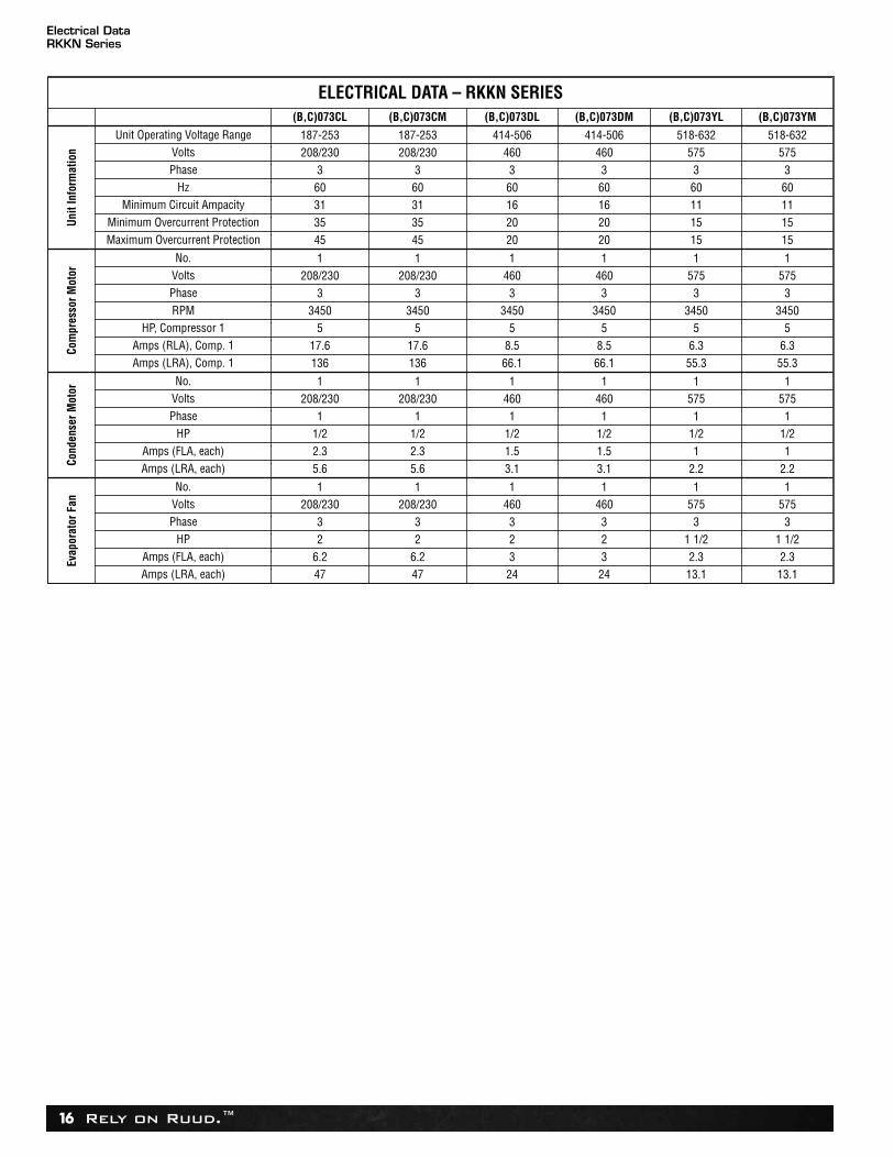
ELECTRICAL DATA – RKKN SERIES(B,C)073CL (B,C)073CM (B,C)073DL (B,C)073DM (B,C)073YL (B,C)073YM
Uni
t Inf
orm
atio
n
Unit Operating Voltage Range 187-253 187-253 414-506 414-506 518-632 518-632Volts 208/230 208/230 460 460 575 575Phase 3 3 3 3 3 3
Hz 60 60 60 60 60 60Minimum Circuit Ampacity 31 31 16 16 11 11
Minimum Overcurrent Protection 35 35 20 20 15 15Maximum Overcurrent Protection 45 45 20 20 15 15
Com
pres
sor M
otor
No. 1 1 1 1 1 1Volts 208/230 208/230 460 460 575 575Phase 3 3 3 3 3 3RPM 3450 3450 3450 3450 3450 3450
HP, Compressor 1 5 5 5 5 5 5Amps (RLA), Comp. 1 17.6 17.6 8.5 8.5 6.3 6.3Amps (LRA), Comp. 1 136 136 66.1 66.1 55.3 55.3
Cond
ense
r Mot
or
No. 1 1 1 1 1 1Volts 208/230 208/230 460 460 575 575Phase 1 1 1 1 1 1
HP 1/2 1/2 1/2 1/2 1/2 1/2Amps (FLA, each) 2.3 2.3 1.5 1.5 1 1Amps (LRA, each) 5.6 5.6 3.1 3.1 2.2 2.2
Evap
orat
or F
an
No. 1 1 1 1 1 1Volts 208/230 208/230 460 460 575 575Phase 3 3 3 3 3 3
HP 2 2 2 2 1 1/2 1 1/2Amps (FLA, each) 6.2 6.2 3 3 2.3 2.3Amps (LRA, each) 47 47 24 24 13.1 13.1
Electrical DataRKKN Series
Rely on Ruud.™ 17
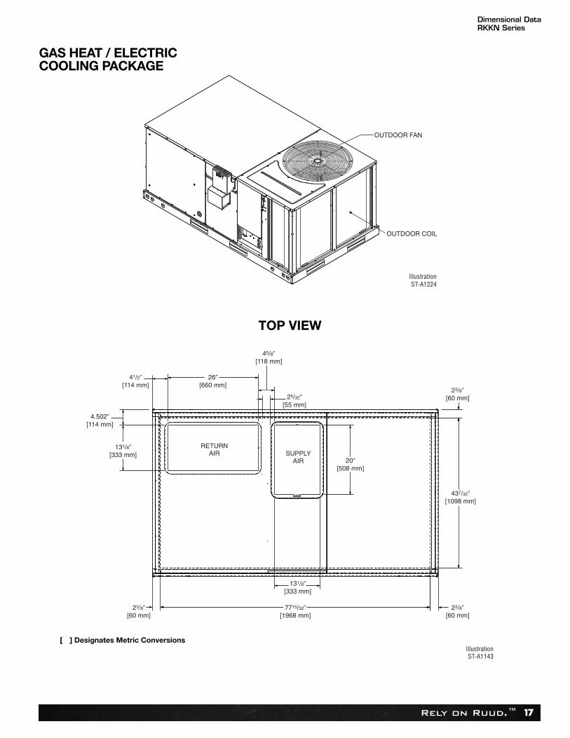
Dimensional DataRKKN Series
41/2�[114 mm]
RETURNAIR SUPPLY
AIR
131/8�[333 mm]
4.502�[114 mm]
45/8�[118 mm]
25/32�[55 mm]
23/8�[60 mm]
23/8�[60 mm]
23/8�[60 mm]
7715/32�[1968 mm]
131/8�[333 mm]
20�[508 mm]
437/32�[1098 mm]
26�[660 mm]
IllustrationST-A1143
[ ] Designates Metric Conversions
TOP VIEW
GAS HEAT / ELECTRICCOOLING PACKAGE
Rely on Ruud.™18
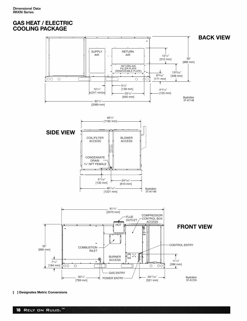
Dimensional DataRKKN Series
[ ] Designates Metric Conversions
SIDE VIEW
BACK VIEW
FRONT VIEW
GAS HEAT / ELECTRICCOOLING PACKAGE
Rely on Ruud.™ 19
Accessory6 Ton [21.1 kW]
Power Exhaust 19 [9]Fresh Air Damper (Manual) 11 [5] 9 [4]
16 [7]
Economizer without Smoke Detector 73 [33] 72 [33]
Economizer with Smoke Detector 76 [34] 75 [34]
Fresh Air Damper (Motorized) 13 [6]Roof Curb 14" 92 [42] 88 [40]
11 [5]
Roof Curb 24" 108 [49] 104 [47]Concentric Diffuser 18" Flush 37 [17] 26 [12]Concentric Diffuser 20" Flush 54 [24] 42 [19]
lbs [kg] lbs [kg]Shipping Operating
Side Discharge Concentric Diffuser RXRN-FA60 35 [16] 20 [9]Side Discharge Concentric Diffuser RXRN-FA65 55 [25] 40 [18]VFD Kit 7 [3] 5 [2]
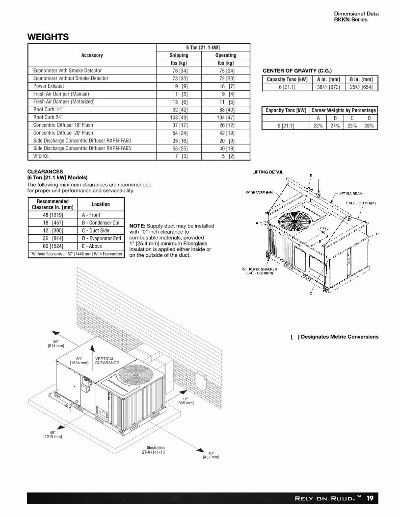
A B C D22% 27% 23% 28%
Capacity Tons [kW]
6 [21.1]
Corner Weights by Percentage
381/4 [972] 253/4 [654]6 [21.1]Capacity Tons [kW] A in. [mm] B in. [mm]
WEIGHTS
CENTER OF GRAVITY (C.G.)
CLEARANCES(6 Ton [21.1 kW] Models)The following minimum clearances are recommendedfor proper unit performance and serviceability.
RecommendedClearance in. [mm] Location
48 [1219] A - Front18 [457] B - Condenser Coil12 [305] C - Duct Side36 [914] D - Evaporator End60 [1524] E - Above
*Without Economizer. 57" [1448 mm] With Economizer
NOTE: Supply duct may be installedwith “0” inch clearance tocombustible materials, provided 1" [25.4 mm] minimum Fiberglassinsulation is applied either inside oron the outside of the duct.
[ ] Designates Metric Conversions
Dimensional DataRKKN Series
Rely on Ruud.™20
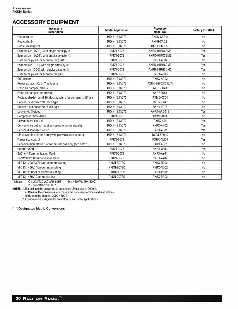
AccessoriesRKKN Series
AccessoryDescription Model Application Accessory
Model No. Factory Installed
Roofcurb, 14" RKKN-(B,C)073 RXKG-CAD14 NoRoofcurb, 24" RKKN-(B,C)073 RXKG-CAD24 NoRoofcurb adapters RKKN-(B,C)073 RXRX-CCCE50 No
Economizer (JADE), with single enthalpy ➁ RKKN-B073 AXRD-01RCCAM3 Yes
Economizer (JADE), with smoke detector ➁ RKKN-B073 AXRD-01RCCBM3 YesDual enthalpy kit for economizer (JADE) RKKN-B073 RXRX-AV04 No
Economizer (DDC) with single enthalpy ➁ RKKN-C073 AXRD-01RHCCM3 Yes
Economizer (DDC) with smoke detector ➁ RKKN-C073 AXRD-01RHCDM3 YesDual enthalpy kit for economizer (DDC) RKKN-C073 RXRX-AV03 NoCO2 sensor RKKN-(B,C)073 RXRX-AR02 NoPower exhaust (C, D, Y voltages) RKKN-(B,C)073 AXRX-BGF03(C,D,Y) NoFresh air damper, manual RKKN-(B,C)073 AXRF-FCA1 NoFresh air damper, motorized RKKN-(B,C)073 AXRF-FCB1 NoRectangular-to-round 20" duct adapters for concentric diffuser RKKN-(B,C)073 RXMC-CC04 NoConcentric diffuser 20", step type RKKN-(B,C)073 RXRN-FA65 NoConcentric diffuser 20", flush type RKKN-(B,C)073 RXRN-FA75 NoLouver kit, 3-sided RKKN-(B,C)073 AXRX-AAD01B YesCompressor time delay RKKN-B073 RXMD-B04 NoLow ambient control RKKN-(B,C)073 RXRX-A04 YesConvenience outlet (requires separate power supply) RKKN-(B,C)073 RXRX-AN02 YesService disconnect switch RKKN-(B,C)073 RXRX-AP01 YesLP conversion kit for Honeywell gas valve (see note 1) RKKN-(B,C)073 RXGJ-EP94D NoFreeze stat control RKKN-B073 RXRX-AM04 YesCanadian high-altitude kit for natural gas only (see note 1) RKKN-(B,C)073 RXRX-AH01 NoComfort Alert RKKN-C073 RXRX-AZ01 YesBACnet® Communication Card RKKN-C073 RXRX-AY01 NoLonWorks™ Communication Card RKKN-C073 RXRX-AY02 NoVFD Kit, 208/230V, Non-communicating RKKN-B073C RXRX-NC02 NoVFD Kit, 460V, Non-communicating RKKN-B073C RXRX-ND02 NoVFD Kit, 208/230V, Communicating RKKN-C073C RXRX-PC02 NoVFD Kit, 460V, Communicating RKKN-C073D RXRX-PD02 No
ACCESSORY EQUIPMENT
*Voltage C = 208/230 VAC-3PH-60HZ D = 460 VAC-3PH-60HZ Y = 575 VAC-3PH-60HZ NOTES: 1. If a unit is to be converted to operate on LP gas above 2000 ft.
in Canada, the conversion kits contain the necessary orifices and instructionsto de-rate the input for 2000-4500 ft.
2. Economizer is designed for downflow or horizontal applications.
[ ] Designates Metric Conversions
Rely on Ruud.™ 21
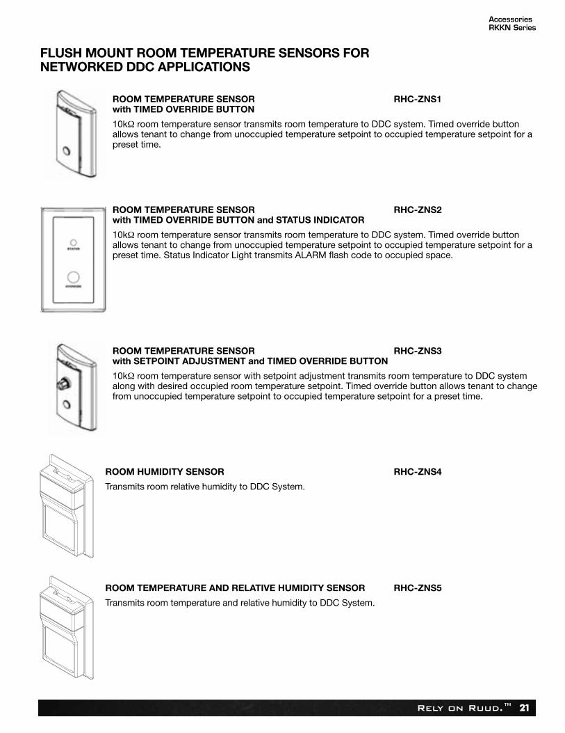
ROOM TEMPERATURE SENSOR RHC-ZNS1with TIMED OVERRIDE BUTTON
10kΩ room temperature sensor transmits room temperature to DDC system. Timed override buttonallows tenant to change from unoccupied temperature setpoint to occupied temperature setpoint for apreset time.
ROOM TEMPERATURE SENSOR RHC-ZNS2with TIMED OVERRIDE BUTTON and STATUS INDICATOR
10kΩ room temperature sensor transmits room temperature to DDC system. Timed override buttonallows tenant to change from unoccupied temperature setpoint to occupied temperature setpoint for apreset time. Status Indicator Light transmits ALARM flash code to occupied space.
ROOM TEMPERATURE SENSOR RHC-ZNS3with SETPOINT ADJUSTMENT and TIMED OVERRIDE BUTTON
10kΩ room temperature sensor with setpoint adjustment transmits room temperature to DDC systemalong with desired occupied room temperature setpoint. Timed override button allows tenant to changefrom unoccupied temperature setpoint to occupied temperature setpoint for a preset time.
ROOM HUMIDITY SENSOR RHC-ZNS4
Transmits room relative humidity to DDC System.
ROOM TEMPERATURE AND RELATIVE HUMIDITY SENSOR RHC-ZNS5
Transmits room temperature and relative humidity to DDC System.
FLUSH MOUNT ROOM TEMPERATURE SENSORS FOR NETWORKED DDC APPLICATIONS
AccessoriesRKKN Series
Rely on Ruud.™22
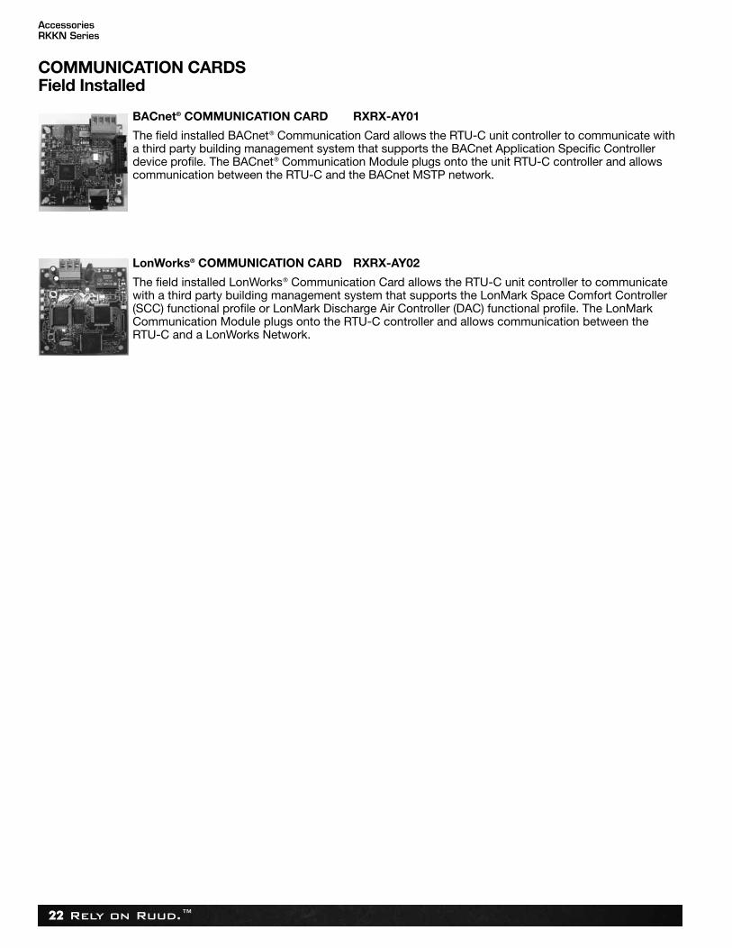
BACnet® COMMUNICATION CARD RXRX-AY01
The field installed BACnet® Communication Card allows the RTU-C unit controller to communicate witha third party building management system that supports the BACnet Application Specific Controllerdevice profile. The BACnet® Communication Module plugs onto the unit RTU-C controller and allowscommunication between the RTU-C and the BACnet MSTP network.
LonWorks® COMMUNICATION CARD RXRX-AY02
The field installed LonWorks® Communication Card allows the RTU-C unit controller to communicatewith a third party building management system that supports the LonMark Space Comfort Controller(SCC) functional profile or LonMark Discharge Air Controller (DAC) functional profile. The LonMarkCommunication Module plugs onto the RTU-C controller and allows communication between the RTU-C and a LonWorks Network.
COMMUNICATION CARDSField Installed
AccessoriesRKKN Series
Rely on Ruud.™ 23
AccessoriesRKKN Series
[ ] Designates Metric Conversions
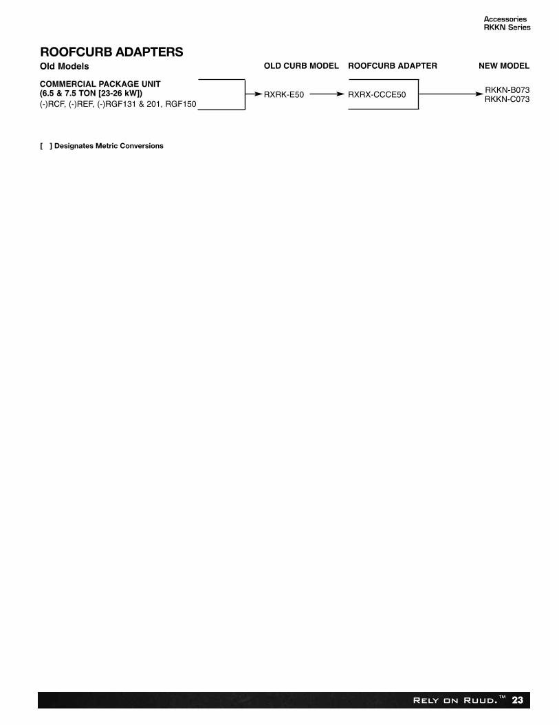
Old Models OLD CURB MODEL ROOFCURB ADAPTER NEW MODEL
COMMERCIAL PACKAGE UNIT(6.5 & 7.5 TON [23-26 kW]) RXRK-E50 RXRX-CCCE50
RKKN-B073RKKN-C073
(-)RCF, (-)REF, (-)RGF131 & 201, RGF150
ROOFCURB ADAPTERS
Rely on Ruud.™24
AccessoriesRKKN Series
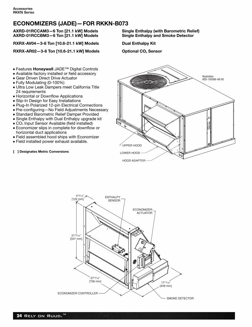
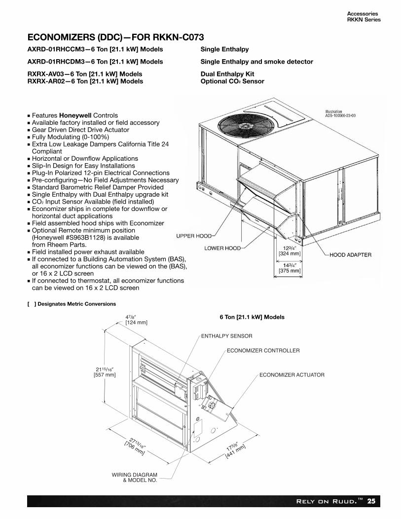
UPPER HOOD
IllustrationADS-100566-48-00
LOWER HOOD
HOOD ADAPTER
ECONOMIZERS (JADE)—FOR RKKN-B073AXRD-01RCCAM3—6 Ton [21.1 kW] Models Single Enthalpy (with Barometric Relief)AXRD-01RCCBM3—6 Ton [21.1 kW] Models Single Enthalpy and Smoke Detector
RXRX-AV04—3-6 Ton [10.6-21.1 kW] Models Dual Enthalpy Kit
RXRX-AR02—3-6 Ton [10.6-21.1 kW] Models Optional CO2 Sensor
■ Features Honeywell JADE™ Digital Controls■ Available factory installed or field accessory■ Gear Driven Direct Drive Actuator■ Fully Modulating (0-100%)■ Ultra Low Leak Dampers meet California Title
24 requirements■ Horizontal or Downflow Applications■ Slip-In Design for Easy Installations■ Plug-In Polarized 12-pin Electrical Connections■ Pre-configuring—No Field Adjustments Necessary■ Standard Barometric Relief Damper Provided■ Single Enthalpy with Dual Enthalpy upgrade kit■ CO2 Input Sensor Available (field installed)■ Economizer slips in complete for downflow or
horizontal duct applications■ Field assembled hood ships with Economizer■ Field installed power exhaust available.
[ ] Designates Metric Conversions
Rely on Ruud.™ 25
ENTHALPY SENSOR
ECONOMIZER CONTROLLER
ECONOMIZER ACTUATOR
WIRING DIAGRAM& MODEL NO.
47/8�[124 mm]
2115/16�[557 mm]
2713/16�[706 mm] 173 /8�
[441 mm]
ECONOMIZERS (DDC)—FOR RKKN-C073AXRD-01RHCCM3—6 Ton [21.1 kW] Models Single Enthalpy
AXRD-01RHCDM3—6 Ton [21.1 kW] Models Single Enthalpy and smoke detector
RXRX-AV03—6 Ton [21.1 kW] Models Dual Enthalpy KitRXRX-AR02—6 Ton [21.1 kW] Models Optional CO2 Sensor
6 Ton [21.1 kW] Models
■ Features Honeywell Controls■ Available factory installed or field accessory■ Gear Driven Direct Drive Actuator■ Fully Modulating (0-100%)■ Extra Low Leakage Dampers California Title 24
Compliant■ Horizontal or Downflow Applications■ Slip-In Design for Easy Installations■ Plug-In Polarized 12-pin Electrical Connections■ Pre-configuring—No Field Adjustments Necessary■ Standard Barometric Relief Damper Provided■ Single Enthalpy with Dual Enthalpy upgrade kit■ CO2 Input Sensor Available (field installed)■ Economizer ships in complete for downflow or
horizontal duct applications■ Field assembled hood ships with Economizer■ Optional Remote minimum position
(Honeywell #S963B1128) is available from Rheem Parts.
■ Field installed power exhaust available■ If connected to a Building Automation System (BAS),
all economizer functions can be viewed on the (BAS),or 16 x 2 LCD screen
■ If connected to thermostat, all economizer functionscan be viewed on 16 x 2 LCD screen
[ ] Designates Metric Conversions
AccessoriesRKKN Series
Rely on Ruud.™26
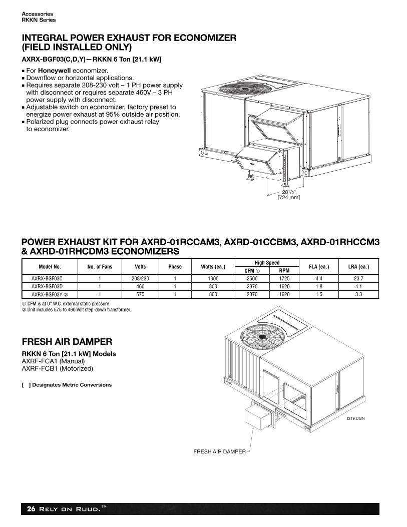
FRESH AIR DAMPERRKKN 6 Ton [21.1 kW] ModelsAXRF-FCA1 (Manual)AXRF-FCB1 (Motorized)
[ ] Designates Metric Conversions
INTEGRAL POWER EXHAUST FOR ECONOMIZER(FIELD INSTALLED ONLY)AXRX-BGF03(C,D,Y)—RKKN 6 Ton [21.1 kW]
■ For Honeywell economizer.■ Downflow or horizontal applications.■ Requires separate 208-230 volt – 1 PH power supply
with disconnect or requires separate 460V – 3 PH power supply with disconnect.
■ Adjustable switch on economizer, factory preset toenergize power exhaust at 95% outside air position.
■ Polarized plug connects power exhaust relay to economizer.
Model No. Volts
AXRX-BGF03C 208/230
AXRX-BGF03Y ➁ 575
No. of Fans
1
1 1
1
Phase
800
1000
Watts (ea.)
2370
2500
High Speed
1620
1725
1.5
4.4
FLA (ea.)
3.3
23.7
LRA (ea.)CFM ➀ RPM
AXRX-BGF03D 4601 1 800 2370 1620 1.8 4.1
POWER EXHAUST KIT FOR AXRD-01RCCAM3, AXRD-01CCBM3, AXRD-01RHCCM3& AXRD-01RHCDM3 ECONOMIZERS
➀ CFM is at 0" W.C. external static pressure.➁ Unit includes 575 to 460 Volt step-down transformer.
FRESH AIR DAMPER
I319.DGN
AccessoriesRKKN Series

Rely on Ruud.™ 27
DUCT ADAPTERS (RKKN-B 6 Ton [21.1 kW] Models)Rectangular to Round Transitions (Downflow)RXMC-CC04 20" [508 mm] Round
[ ] Designates Metric Conversions
Accessory Model No. Size in. [mm]RXMC-CB03 18 [457] RoundRXMC-CC04 20 [508] Round
Model Application Tons [kW]3-5 [10.6-17.6]6 [21.1]
AccessoriesRKKN Series
Rely on Ruud.™28
AccessoriesRKKN Series
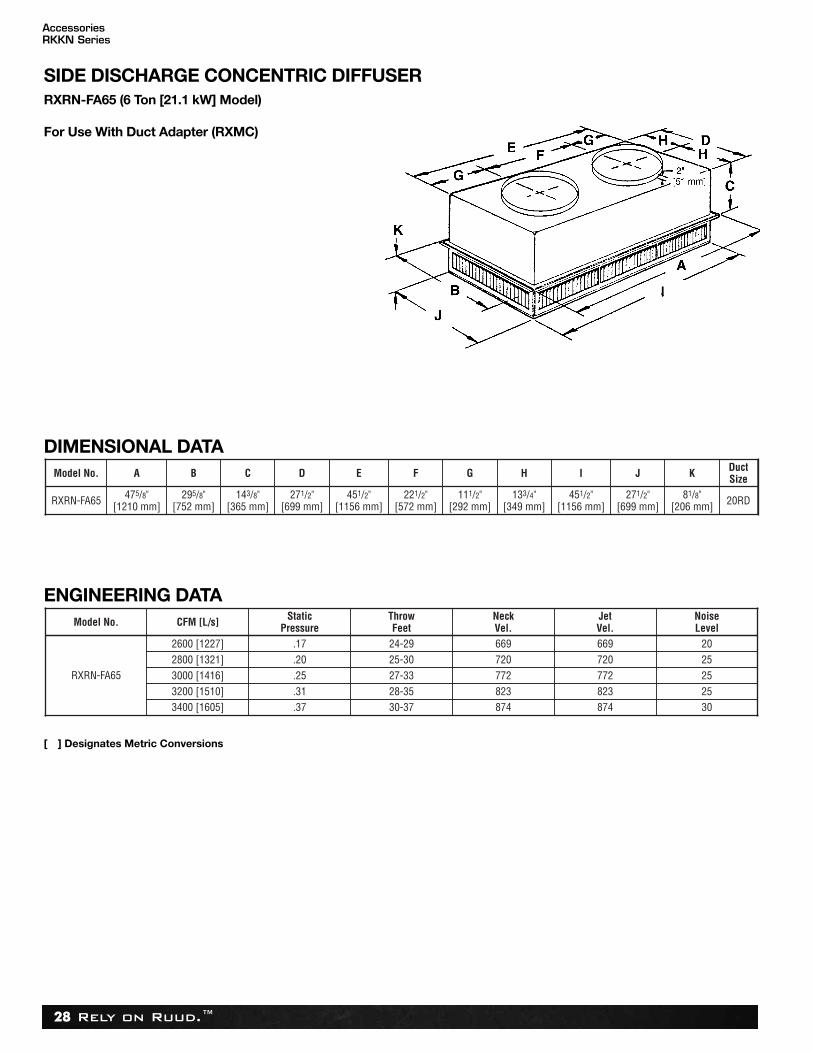
SIDE DISCHARGE CONCENTRIC DIFFUSERRXRN-FA65 (6 Ton [21.1 kW] Model)
Model No. A B C D E F G H I J K DuctSize
RXRN-FA65 475/8"[1210 mm]
295/8"[752 mm]
143/8"[365 mm]
271/2"[699 mm]
451/2"[1156 mm]
221/2"[572 mm]
111/2"[292 mm]
133/4"[349 mm]
451/2"[1156 mm]
271/2"[699 mm]
81/8"[206 mm] 20RD
Model No. CFM [L/s] StaticPressure
ThrowFeet
NeckVel.
JetVel.
NoiseLevel
RXRN-FA65
2600 [1227] .17 24-29 669 669 202800 [1321] .20 25-30 720 720 253000 [1416] .25 27-33 772 772 253200 [1510] .31 28-35 823 823 253400 [1605] .37 30-37 874 874 30
DIMENSIONAL DATA
ENGINEERING DATA
[ ] Designates Metric Conversions
For Use With Duct Adapter (RXMC)
Rely on Ruud.™ 29
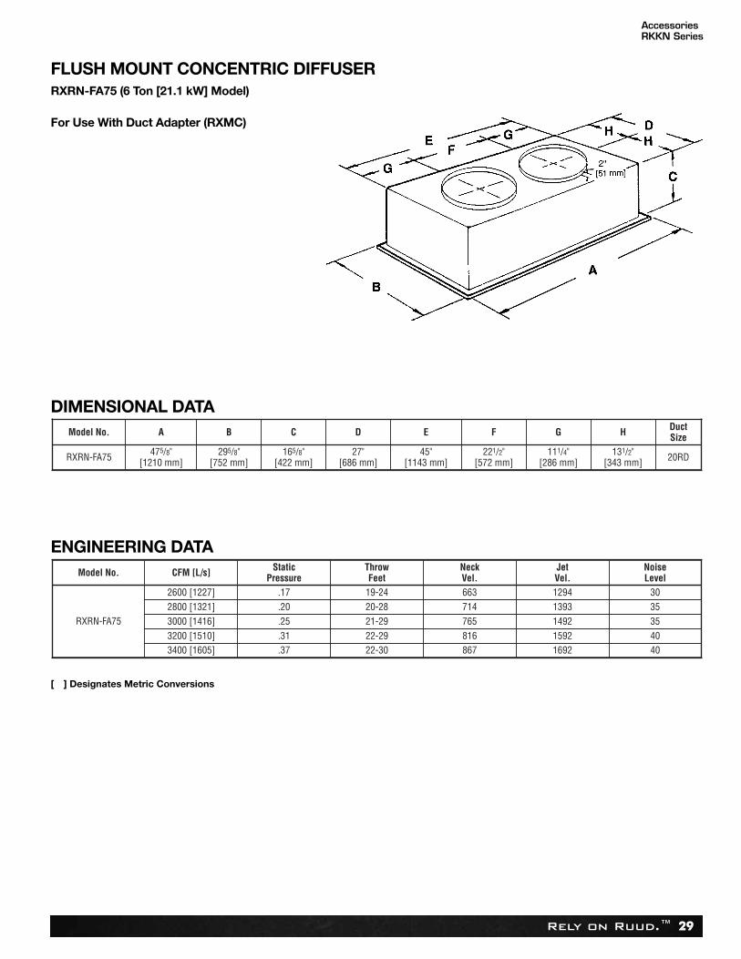
FLUSH MOUNT CONCENTRIC DIFFUSERRXRN-FA75 (6 Ton [21.1 kW] Model)
DIMENSIONAL DATA
ENGINEERING DATA
Model No. A B C D E F G H DuctSize
RXRN-FA75 475/8"[1210 mm]
295/8"[752 mm]
165/8"[422 mm]
27"[686 mm]
45"[1143 mm]
221/2"[572 mm]
111/4"[286 mm]
131/2"[343 mm] 20RD
Model No. CFM [L/s] StaticPressure
ThrowFeet
NeckVel.
JetVel.
NoiseLevel
RXRN-FA75
2600 [1227] .17 19-24 663 1294 302800 [1321] .20 20-28 714 1393 353000 [1416] .25 21-29 765 1492 353200 [1510] .31 22-29 816 1592 403400 [1605] .37 22-30 867 1692 40
[ ] Designates Metric Conversions
For Use With Duct Adapter (RXMC)
AccessoriesRKKN Series
Rely on Ruud.™30
TYPICAL INSTALLATION
AccessoriesRKKN Series
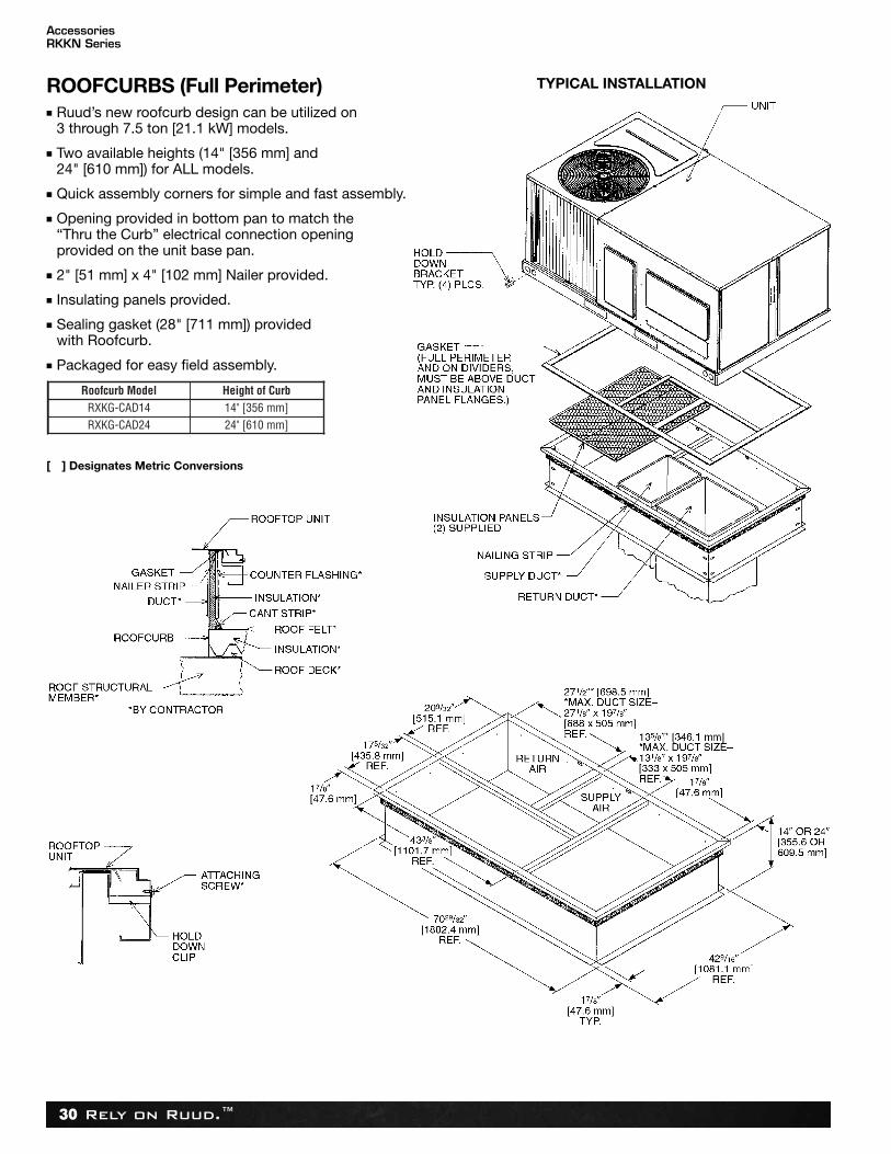
ROOFCURBS (Full Perimeter)n Ruud’s new roofcurb design can be utilized on
3 through 7.5 ton [21.1 kW] models.
n Two available heights (14" [356 mm] and24" [610 mm]) for ALL models.
n Quick assembly corners for simple and fast assembly.
n Opening provided in bottom pan to match the “Thru the Curb” electrical connection opening provided on the unit base pan.
n 2" [51 mm] x 4" [102 mm] Nailer provided.
n Insulating panels provided.
n Sealing gasket (28" [711 mm]) providedwith Roofcurb.
n Packaged for easy field assembly.
Roofcurb Model Height of CurbRXKG-CAD14 14" [356 mm]RXKG-CAD24 24" [610 mm]
[ ] Designates Metric Conversions
Rely on Ruud.™ 31
Mechanical SpecificationsRKKN Series
GUIDE SPECIFICATIONS – RKKN-B073/RKKN-C073You may copy this document directly into your building specification. This specification is written to comply with the 2004 version of the“master format” as published by the Construction Specification Institute. www.csinet.org.
GAS HEAT PACKAGED ROOFTOPHVAC Guide SpecificationsSize Range: 6 Nominal TonsSection Description23 06 80 Schedules for Decentralized HVAC Equipment
23 06 80.13 Decentralized Unitary HVAC Equipment Schedule23 06 80.13.A. Rooftop unit schedule 1. Schedule is per the project specification requirements.
23 07 16 HVAC Equipment Insulation 23 07 16.13 Decentralized, Rooftop Units: 1. Interior cabinet surfaces shall be insulated with a minimum 3/4-in. thick, minimum 1-1/2 lb density, flexible fiberglass insulation bonded with a phenolic binder, with aluminum foil facing on the air side. 2. Insulation and adhesive shall meet NFPA 90A requirements for flame spread and smoke generation.23 09 13 Instrumentation and Control Devices for HVAC 23 09 13.23 Sensors and Transmitters: 23 09 13.23.A. Thermostats 1. Thermostat must a. have capability to energize 2 different stages of cooling, and 1 stage of heating. b. must include capability for occupancy scheduling.23 09 23 Direct-digital Control system for HVAC (RKKN-C073 only) 23 09 23.13 Decentralized, Rooftop Units: 23 09 23.13.A. RTU-C controller 1. Shall be ASHRAE 62-2001 compliant. 2. Shall accept 18-32VAC input power. 3. Shall have an operating temperature range from -40ºF (-40ºC) to 158ºF (70ºC), 10% - 95% RH (non-condensing). 4. Controller shall accept the following inputs: space temperature, setpoint adjustment, outdoor air temperature, indoor air qual-
ity, outdoor air enthalpy, fire shutdown, return air enthalpy, fan status, remote time clock/door switch. 5. Shall accept a CO2 sensor in the conditioned space, and be Demand Control Ventilation (DCV) ready. 6. Shall provide the following outputs: Economizer, fan, cooling stage 1, cooling stage 2, heat stage 1, heat stage 2, heat stage
3/ exhaust/ occupied. 7. Unit shall provide surge protection for the controller through a circuit breaker. 8. Shall have a field installed communication card allowing the unit to be Internet capable, and communicate at a Baud rate of
19.2K or faster. 9. Shall have an LED display independently showing the status of activity on the communication bus, and processor operation. 10. Shall have either a field installed BACnet® plug-in communication card which includes an EIA-485 protocol communication
port, or a field installed LonWorks™ plug-in communications card. 11. Software upgrades will be accomplished by local download. Software upgrades through chip replacements are not allowed. 12. Shall be shock resistant in all planes to 5G peak, 11ms during operation, and 100G peak, 11ms during storage. 13. Shall be vibration resistant in all planes to 1.5G @ 20-300 Hz. 14. Shall support a bus length of 4000 ft max, 60 devices per 1000 ft section, and 1 RS-485 repeater per 1000 ft sections. 23 09 23.13.B. Open protocol, direct digital controller: 1. Shall be ASHRAE 62-2001 compliant. 2. Shall accept 18-30VAC, 50-60Hz, and consume 15VA or less power. 3. Shall have an operating temperature range from -40ºF (-40ºC) to 130ºF (54ºC), 10% - 90% RH (non-condensing). 4. Shall have either a field installed BACnet® plug-in communication card which includes an EIA-485 protocol communication
port, or a field installed LonWorks™ plug-in communications card. 5. The BACnet® plug in communication card shall include built-in protocol for BACNET (MS/TP and PTP modes). 6. The LonWorks™ plug in communication card shall include the Echelon processor required for all Lon applications. 7. Shall allow access of up to 62 network variables (SNVT). Shall be compatible with all open controllers. 8. Baud rate Controller shall be selectable through the EIA-485 protocol communication port. 9. Shall have an LED display independently showing the status of serial communication, running, errors, power, all digital out-
puts, and all analog inputs. 10. Shall accept the following inputs: space temperature, setpoint adjustment, outdoor air temperature, indoor air quality, outdoor
air enthalpy, compressor lock-out, fire shutdown, enthalpy switch, and fan status/filter status/ humidity/ remote occupancy. 11. Shall provide the following outputs: economizer, fan, cooling stage 1, cooling stage 2, heat stage 1, heat stage 2, heat stage
3/ exhaust. 12. Software upgrades will be accomplished by either local or remote download. No software upgrades through chip replace-
ments are allowed.
Rely on Ruud.™32
Mechanical SpecificationsRKKN Series
23 09 33 Electric and Electronic Control System for HVAC 23 09 33.13 Decentralized, Rooftop Units: 23 09 33.13.A. General: 1. Shall be complete with self-contained low-voltage control circuit protected by a replaceable fuse on the 24-v transformer
side. Transformer size is 40VA. 2. Shall utilize color-coded wiring. 3. Unit shall provide a minimum of one 10-pin screw terminal connection board for connection of control wiring. 4. Shall include a central control terminal board to conveniently and safely provide connection points for vital control functions
such as: smoke detectors, phase monitor, economizer, thermostat, DDC control options, loss of charge, freeze sensor, highpressure switches.
5. The heat exchanger shall be controlled by an integrated furnace controller (IFC) microprocessor. See heat exchanger sectionof this specification.
23 09 33.13.B. Safeties: 1. Compressor over-temperature, over current. 2. Loss of charge switch. a. Units with 2 compressors shall have different colored wires for the circuit 1 and circuit 2 low and high pressure switches. b. Loss of charge switch shall use different color wire than the high pressure switch. The purpose is to assist the installer and
service technician to correctly wire and or troubleshoot the rooftop unit. c. Loss of charge switch shall have a different sized connector than the high pressure switch. They shall physically prevent
the cross-wiring of the safety switches between the high and low pressure side of the system. 3. High-pressure switch. a. Units with 2 compressors shall have different colored wires for the circuit 1 and circuit 2 low and high pressure switches. b. High pressure switch shall use different color wire than the low pressure switch. The purpose is to assist the installer and
service person to correctly wire and or troubleshoot the rooftop unit. c. High pressure switch shall have a different sized connector than the loss of charge switch. They shall physically prevent the
cross-wiring of the safety switches between the high and low pressure side of the system. 4. Automatic reset, motor thermal overload protector. 5. Freeze protection sensor, evaporator coil. 6. Heating section shall be provided with the following minimum protections. a. High-temperature limit switches. b. Induced draft motor pressure switch. c. Flame rollout switch. d. Flame proving controls.23 09 93 Sequence of Operations for HVAC Controls23 09 93.13 Decentralized, Rooftop Units: 23 09 93.13 INSERT SEQUENCE OF OPERATION23 40 13 Panel Air Filters 23 40 13.13 Decentralized, Rooftop Units: 23 40 13.13.A. Standard filter section 1. Shall consist of factory-installed, low velocity, throwaway 1-in. thick fiberglass filters of commercially available sizes. 2. Unit shall use only one filter size. Multiple sizes are not acceptable. 3. Filter face velocity shall not exceed 365 fpm at nominal airflows. 4. Filters shall be accessible through an access panel as described in the unit cabinet section of the specification
(23 81 19.13.H). 5. Filter rack will also accept 2-in thick fiberglass filters of commercially available sizes by removal of a tab.23 81 19 Self-Contained Air Conditioners23 81 19.13 Small-Capacity Self-Contained Air Conditioners 23 81 19.13.A. General 1. Outdoor, rooftop mounted, electrically controlled, heating and cooling unit utilizing a hermetic scroll compressor for cooling
duty and gas combustion for heating duty. 2. Factory assembled, single-piece heating and cooling rooftop unit. Contained within the unit enclosure shall be all factory
wiring, piping, controls, and special features required prior to field start-up. 3. Unit shall use environmentally safe, R-410A refrigerant. 4. Unit shall be installed in accordance with the manufacturer’s instructions. 5. Unit must be selected and installed in compliance with local, state, and federal codes. 23 81 19.13.B. Quality Assurance 1. Unit meets ASHRAE 90.1-2010 minimum efficiency requirements. 2. Unit shall be rated in accordance with AHRI Standards 210/240. 3. Unit shall be designed to conform to ASHRAE 15-2010. 4. Unit shall be UL-tested and certified in accordance with ANSI Z21.47 Standards and UL-listed and certified under Canadian
standards as a total package for safety requirements. 5. Insulation and adhesive shall meet NFPA 90A requirements for flame spread and smoke generation. 6. Unit casing shall be capable of withstanding 500-hour salt spray exposure per ASTM B117 (scribed specimen).
Rely on Ruud.™ 33
7. Unit casing shall be capable of withstanding Federal Test Method Standard No. 141 (Method 6061) 5000-hour salt spray. 8. Unit shall be designed in accordance with ISO 9001:2008, and shall be manufactured in a facility registered by ISO
9001:2008. 9. Roof curb shall be designed to conform to NRCA Standards. 10. Unit shall be subjected to a completely automated run test on the assembly line. The data for each unit will be stored at the
factory, and must be available upon request. 11. Unit shall be designed in accordance with UL Standard 1995, including tested to withstand rain. 12. Unit shall be constructed to prevent intrusion of snow and tested to prevent snow intrusion into the control box up to 40 mph. 23 81 19.13.C. Delivery, Storage, and Handling 1. Unit shall be stored and handled per manufacturer’s recommendations. 2. Lifted by crane requires either shipping top panel or spreader bars. 3. Unit shall only be stored or positioned in the upright position. 23 81 19.13.E. Project Conditions 1. As specified in the contract. 23 81 19.13.F. Operating Characteristics 1. Unit shall be capable of starting and running at 115°F (46°C) ambient outdoor temperature, meeting maximum load criteria of
AHRI Standard 210/240 at ± 10% voltage. 2. Compressor with standard controls shall be capable of operation down to 40°F (4°C), ambient outdoor temperatures. Acces-
sory low ambient kit is necessary if mechanically cooling at ambient temperatures below 40°F (4°C). 3. Unit shall discharge supply air vertically or horizontally as shown on contract drawings. 4. Unit shall be factory configured for vertical supply & return configurations. 5. Unit shall be field convertible from vertical to horizontal configuration. 23 81 19.13.G. Electrical Requirements 1. Main power supply voltage, phase, and frequency must match those required by the manufacturer. 23 81 19.13.H. Unit Cabinet 1. Unit cabinet shall be constructed of galvanized steel, and shall be bonderized and coated with a Pre-paint baked enamel
finish on all externally exposed surfaces. 2. Unit cabinet exterior paint shall be: film thickness, (dry) 0.003 inches minimum, gloss (per ASTM D523, 60°F / 16°C): 60,Hard-
ness: H-2H Pencil hardness. 3. Evaporator fan compartment interior cabinet insulation shall conform to AHRI Standards 210/240 minimum exterior sweat cri-
teria. Interior surfaces shall be insulated with a minimum 3/4-in. thick, 1 lb. density, flexible fiberglass insulation, aluminumfoil-face coated on the air side.
4. Base of unit shall have locations for thru-the-base gas and electrical connections (factory installed or field installed), standard. 5. Base Rail a. Unit shall have base rails on all sides. b. Holes shall be provided in the base rails for rigging shackles to facilitate maneuvering and overhead rigging. c. Holes shall be provided in the base rail for moving the rooftop by fork truck. d. Base rail shall be a minimum of 14 gauge thickness. 6. Condensate pan and connections: a. Shall be a condensate drain pan made of a non-corrosive material. Unit must be installed at a slight angle to allow for com-
plete drainage. b. Shall comply with ASHRAE Standard 62. c. Shall use a 3/4” x 14 NPT drain connection through the side of the drain pan. Connection shall be made per manufacturer’s
recommendations. 7. Electrical Connections a. All unit power wiring shall enter unit cabinet at a single, factory-prepared, knockout location. b. Thru-the-base capability ii. Standard unit shall have a thru-the-base electrical location(s) using a raised, embossed portion of the unit basepan. ii. No basepan penetration, other than those authorized by the manufacturer, is permitted. 8. Component access panels (standard) a. Cabinet panels shall be easily removable for servicing. 9. Component access panels (Optional) a. Panels covering control box, indoor blower assembly, indoor blower motor, and air filters shall have metal hinges and
1/4 turn latches. 10. Gas Connections: a. All gas piping connecting to unit gas valve shall enter the unit cabinet at a single location on side of unit (horizontal plane). b. Thru-the-base capability ii. Standard unit shall have a thru-the-base gas-line location using a raised, embossed portion of the unit basepan. ii. No basepan penetration, other than those authorized by the manufacturer, is permitted. 23 81 19.13.I. Gas Heat 1. General a. Heat exchanger shall be an induced draft design. Positive pressure heat exchanger designs shall not be allowed. b. Shall incorporate a direct-spark ignition system and redundant main gas valve.
Mechanical SpecificationsRKKN Series
Rely on Ruud.™34
Mechanical SpecificationsRKKN Series
c. Heat exchanger design shall allow combustion process condensate to gravity drain; maintenance to drain the gas heatexchanger shall not be required.
d. Gas supply pressure at the inlet to the rooftop unit gas valve must match that required by the manufacturer. 2. The heat exchanger shall be controlled by an integrated furnace controller (IFC) microprocessor. a. IFC board shall notify users of fault using an LED (light-emitting diode). 3. Standard Heat Exchanger construction a. Heat exchanger shall be of the tubular-section type constructed of a minimum of 20-gauge aluminum coated steel for cor-
rosion resistance. b. Burners shall be of the in-shot type constructed of aluminum-coated steel. c. Burners shall incorporate orifices for rated heat output up to 2000 ft (610m) elevation. Additional accessory kits may be
required for applications above 2000 ft (610m) elevation, depending on local gas supply conditions. 4. Optional Stainless Steel Heat Exchanger construction a. Use energy saving, direct-spark ignition system. b. Use a redundant main gas valve. c. Burners shall be of the in-shot type constructed of aluminum-coated steel. d. All gas piping shall enter the unit cabinet at a single location on side of unit (horizontal plane). e. The optional stainless steel heat exchanger shall be of the tubular-section type, constructed of a minimum of 20-gauge
type 409 stainless steel. f. Type 409 stainless steel shall be used in heat exchanger tubes and vestibule plate. g. Complete stainless steel heat exchanger allows for greater application flexibility. 5. Induced draft combustion motors and blowers a. Shall be a direct-drive, single inlet, forward-curved centrifugal type. b. Shall be made from steel with a corrosion-resistant finish. c. Shall have permanently lubricated sealed bearings. d. Shall have inherent thermal overload protection. e. Shall have an automatic reset feature. 23 81 19.13.J. Coils 1. Aluminum MicroChannel evaporator and condenser coils on all models. a. Shall have aluminum lanced fins thermally bonded to aluminum multi-port flat tube design (microchannel) tubes. Coils shall
be furnace brazed and contain epoxy lined shrink wrap on all aluminum to copper connections. b. Shall be leak tested using helium mass spectrometry. The leak rate shall not exceed 6.5 x 10⁻⁵ sccs of 100% helium at 200
psig, and qualified to UL 1995 burst test at 1950 psig. c. Evaporator coil includes internal distributor plate to prevent mal-distribution of two-phase refrigerant. 23 81 19.13.K. Refrigerant Components 1. Refrigerant circuit shall include the following control, safety, and maintenance features: a. Thermal Expansion Valves (TXV). b. Refrigerant filter drier. c. Service gauge connections on suction and liquid lines. d. External pressure gauge ports access shall be located in front exterior of cabinet. 2. Compressors a. Unit shall use one fully hermetic, scroll compressor. b. Compressor motors shall be cooled by refrigerant gas passing through motor windings. c. Compressors shall be internally protected from high discharge temperature conditions. d. Compressors shall be protected from an over-temperature and over-amperage conditions by an internal, motor over-
load device. e. Compressor shall be factory mounted on rubber grommets. f. Compressor motors shall have internal line break thermal and current overload protection along with high pressure differ-
ential protection. g. Crankcase heaters shall not be required for normal operating range. 23 81 19.13.L. Filter Section 1. Filters access is specified in the unit cabinet section of this specification. 2. Shall consist of factory-installed, low velocity, throw-away 1-in. thick fiberglass filters. 3. Filter face velocity shall not exceed 365 fpm at nominal airflows. 4. Filters shall be standard, commercially available sizes. 5. Only one size filter per unit is allowed. 6. Filter rack will also accept 2-in thick fiberglass filters of commercially available sizes by removal of a tab. 23 81 19.13.M. Evaporator Fan and Motor 1. Evaporator fan motor: a. Shall have permanently lubricated bearings. b. Shall have inherent automatic-reset thermal overload protection. c. Shall have a maximum continuous bhp rating for continuous duty operation; no safety factors above that rating shall be
required.
Rely on Ruud.™ 35
2. Belt-driven Evaporator Fan: a. Belt drive shall include an adjustable-pitch motor pulley. b. Shall use sealed, permanently lubricated ball-bearing type. c. Blower fan shall be double-inlet type with forward-curved blades. d. Shall be constructed from steel with a corrosion resistant finish and dynamically balanced. 3. High-Static Belt-driven Evaporator Fan Motor(s) and Drive(s): a. High-static motor(s) and drive(s) shall be factory-installed to provide additional performance range. 23 81 19.13.N. Condenser Fans and Motors 1. Condenser fan motors: a. Shall be a totally enclosed motor. b. Shall use permanently lubricated bearings. c. Shall have inherent thermal overload protection with an automatic reset feature. d. Shall use a shaft-down design. Shaft-up designs including those with “rain-slinger devices” shall not be allowed. 2. Condenser Fans shall: a. Shall be a direct-driven propeller type fan b. Shall have aluminum blades riveted to corrosion-resistant steel spiders and shall be dynamically balanced. 23 81 19.13.O. Special Features 1. Integrated Economizers: a. Integrated, gear-driven parallel modulating blade design type capable of simultaneous economizer and compressor operation. b. Module designed for vertical or horizontal return configurations. Vertical return configuration shall be available as a factory
installed option. c. Damper blades shall be galvanized steel with metal gears. Plastic or composite blades on intake or return shall not be
acceptable. d. Shall include all hardware and controls to provide free cooling with outdoor air when temperature and/or humidity are
below setpoints. e. Shall be equipped with gear driven dampers for both the outdoor ventilation air and the return air for positive air
stream control. f. Shall be capable of introducing up to 100% outdoor air. g. Shall be equipped with a barometric relief damper capable of relieving up to 100% return air. The barometric relief damper
shall include seals, hardware and hoods to relieve building pressure. Damper shall gravity close upon unit shut down. h. Shall be designed to close damper(s) during loss-of-power situations with spring return built into motor. i. An outdoor single-enthalpy sensor shall be provided as standard. Outdoor air enthalpy set point shall be adjustable and
shall range from the enthalpy equivalent of 63°F @ 50% rh to 73°F @ 50% rh. Additional sensor options shall be availableas accessories.
j. The economizer controller shall also provide control of an accessory power exhaust unit function. Factory set at 70%, witha range of 0% to 100%.
k. The economizer shall maintain minimum airflow into the building during occupied period and provide design ventilationrate for full occupancy.
l. Economizer controller shall accept a 0-10Vdc CO2 sensor input over a CO2 range of 0-2000 ppm for IAQ/DCV control. Inthis mode, dampers shall modulate the outdoor-air damper to provide ventilation based on the sensor input.
m. Actuator shall be direct coupled to economizer gear. No linkage arms or control rods shall be acceptable. n. Economizer controller shall provide indications when in free cooling mode, in the DCV mode, or the exhaust fan contact
is closed. o. Ultra Low Leak Dampers shall meet California Title 24 requirements. p. Economizer controller shall meet California Title 24 FDD (Fault Detection and Diagnostics) requirement. 2. Two-Position Damper a. Damper shall be a Two-Position Damper. Damper travel shall be from the full closed position to the field adjustable %-open
setpoint. b. Damper shall include adjustable damper travel from 25% to 100% (full open). c. Damper shall include single or dual blade, gear driven damper and actuator motor. d. Actuator shall be direct coupled to economizer gear. No linkage arms or control rods shall be acceptable. e. Damper will admit up to 100% outdoor air for applicable rooftop units. f. Damper shall close upon indoor (evaporator) fan shutoff and/or loss of power. g. The damper actuator shall plug into the rooftop unit’s wiring harness plug. No hard wiring shall be required. h. Outside air hood shall include aluminum water entrainment filter. 3. Manual damper a. Manual damper package shall consist of damper, air inlet screen, and rain hood which can be preset to admit up to 50%
outdoor air for year round ventilation. 4. Head Pressure Control Package a. Controller shall control coil head pressure by condenser-fan cycling. 5. Condenser Coil Hail Guard Assembly a. Shall protect against damage from hail. b. Shall be louvered design.
Mechanical SpecificationsRKKN Series
Rely on Ruud.™36
Mechanical SpecificationsRKKN Series
6. Thru-the-Base Connectors: a. Kits shall provide connectors to permit gas and electrical connections to be brought to the unit through the unit basepan. 7. Propeller Power Exhaust: a. Power exhaust shall be used in conjunction with an integrated economizer. b. Independent modules for vertical or horizontal return configurations shall be available. c. Horizontal power exhaust shall be mounted in return ductwork. d. Power exhaust shall be controlled by economizer controller operation. Exhaust fans shall be energized when dampers
open past the 0-100% adjustable setpoint on the economizer control. 8. Roof Curbs (Vertical): a. Full perimeter roof curb with exhaust capability providing separate airstreams for energy recovery from the exhaust air
without supply air contamination. b. Formed galvanized steel with wood nailer strip and shall be capable of supporting entire unit weight. c. Permits installation and securing of ductwork to curb prior to mounting unit on the curb. 9. Outdoor Air Enthalpy Sensor: a. The outdoor air enthalpy sensor shall be used to provide single enthalpy control. When used in conjunction with a return air
enthalpy sensor, the unit will provide differential enthalpy control. The sensor allows the unit to determine if outside air issuitable for free cooling.
10. Return Air Enthalpy Sensor: a. The return air enthalpy sensor shall be used in conjunction with an outdoor air enthalpy sensor to provide differential
enthalpy control. 11. Indoor Air Quality (CO2) Sensor: a. Shall be able to provide demand ventilation indoor air quality (IAQ) control. b. The IAQ sensor shall be available in wall mount with LED display. The set point shall have adjustment capability. c. The sensor shall provide a 0-10Vdc output for a CO2 input range of 0-2000 ppm. 12. Smoke detectors: a. Shall be a Four-Wire Controller and Detector. b. Shall be environmental compensated with differential sensing for reliable, stable, and drift-free sensitivity. c. Shall use magnet-activated test/reset sensor switches. d. Shall have a recessed momentary switch for testing and resetting the detector. e. Controller shall include: i. One set of normally open alarm initiation contacts for connection to an initiating device circuit on a fire alarm control panel ii. Two Form-C auxiliary alarm relays for interface with rooftop unit or other equipment. iii. One Form-C supervision (trouble) relay to control the operation of the Trouble LED on a remote test/reset station. iv. Capable of direct connection to two individual detector modules. v. Can be wired to up to 14 other duct smoke detectors for multiple fan shutdown applications. 13. Non-Powered convenience outlet. a. Outlet shall be powered from a separate 115-120v power source. b. A transformer shall not be included. c. Outlet shall be field-installed and internally mounted with easily accessible 115-v female receptacle. d. Outlet shall include 15 amp GFI receptacle. e. Outlet shall be accessible from outside the unit. f. Outlet shall have a wet location, while in use cover 14. Unit-Mounted, Non-Fused Disconnect Switch: a. Switch shall be factory-installed, internally mounted. b. National Electric Code (NEC) and UL approved non-fused switch shall provide unit power shutoff. c. Shall be accessible from outside the unit. d. Shall provide local shutdown and lockout capability. 15. Universal Gas Conversion Kit: a. Package shall contain all the necessary hardware and instructions to convert a standard natural gas unit to operate from
2000-7000 ft (610 to 2134m) elevation with natural gas or from 0-7000 ft (90-2134m) elevation with liquefied propane. 16. Liquid Propane (LP) Conversion Kit a. Package shall contain all the necessary hardware and instructions to convert a standard natural gas unit for use with lique-
fied propane, up to 2000 ft (610m) elevation. 17. Flue Discharge Deflector: a. Flue discharge deflector shall direct unit exhaust vertically instead of horizontally. b. Deflector shall be defined as a “natural draft” device by the National Fuel and Gas (NFG) code. 18. Fan/Filter Status Switch: a. Switch shall provide status of indoor evaporator fan (ON/OFF) or filter (CLEAN/DIRTY). b. Status shall be displayed either over communication bus (when used with direct digital controls) or through the controller
LCD display inside the unit control box.
Rely on Ruud.™ 37
GENERAL TERMS OF LIMITED WARRANTY*Ruud will furnish a replacement for any part of this productwhich fails in normal use and service within the applicableperiods stated, in accordance with the terms of the limited warranty.
Heat Exchanger .................................................Ten (10) Years*For complete details of the Limited and Conditional Warranties, includingapplicable terms and conditions, contact your local contractor or theManufacturer for a copy of the product warranty certificate.
Compressor 3 Phase, Commercial Applications ..................Five (5) YearsParts 3 Phase, Commercial Applications....................One (1) YearFactory Standard Heat Exchanger 3 Phase, Commercial Applications.................Ten (10) Years
BEFORE PURCHASING THIS APPLIANCE, READ IMPORTANT ENERGY COST AND EFFICIENCY INFORMATION AVAILABLE FROMYOUR RETAILER.
Limited WarrantyRKKN Series

NotesRKKN Series
Rely on Ruud.™38

NotesRKKN Series
Rely on Ruud.™ 39
Rely on Ruud.™
PRINTED IN U.S.A. 11/18 QG FORM NO. R22-868 REV. 4
Rely on Ruud.™
Ruud Heating, Cooling & Water Heating • P.O. Box 17010Fort Smith, Arkansas 72917 • www.ruud.com
In keeping with its policy of continuous progress and product improvement, Ruud reserves the right to make changes without notice.
Ruud Canada • 125 Edgeware Road, Unit 1Brampton, Ontario • L6Y 0P5