Russellstoll Electrical Interconnection Systems® E6 Electrical Interconnection Systems UniGard®...
52
Russellstoll ® E1 www.tnb.ca Electrical Interconnection Systems UniGard ® Pin and Sleeve IEC Connector ...............................................E2 UniGard ® Safety, Performance and Durability .......................................E3 UniGard ® The Difference......................................................................E4 UniGard ® Global Configuration Standards ............................................E5 UniGard ® Watertight and Splashproof Pin and Sleeve Devices IP67 and IP44....................................................E6–E10 UniGard ® IEC 309 Safety Interlock .............................................E11–E13 UniGard ® Series Specifications North American Amperages ...............E14 UniGard ® Series IP44 Dimensions......................................................E15 UniGard ® Series IP67 Dimensions..............................................E16–E17 Dura-Gard ® Nonmetallic Waterproof Connections ......................E18–E27 FS/FD TM Metallic Connections .....................................................E28–E31 FS/FD TM Dimensions ...........................................................................E32 FS/FD TM Accessories ...........................................................................E33 FS/FD TM Conduit Boxes .......................................................................E34 FS/FD TM Adapters and Boxes.......................................................E35–E36 FS/FD TM Mechanically Interlocked Receptacles ...........................E37–E39 Computer System Interconnections ...................................................E40 Computer System Plugs, Connectors and Receptacles ...............E41–E46 Connections for Data Center Installation ....................................E47–E48 Safe Ground Indicator System ...................................................E49–E51 Other Russellstoll ® Products ..............................................................E52 Table of Contents
Transcript of Russellstoll Electrical Interconnection Systems® E6 Electrical Interconnection Systems UniGard®...
Russellstoll ®
E1w w w . t n b . c a
Electrical Interconnection Systems
UniGard® Pin and Sleeve IEC Connector...............................................E2
UniGard® Safety, Performance and Durability.......................................E3
UniGard® The Difference......................................................................E4
UniGard® Global Configuration Standards ............................................E5
UniGard® Watertight and Splashproof Pin and
Sleeve Devices IP67 and IP44....................................................E6–E10
UniGard® IEC 309 Safety Interlock .............................................E11–E13
UniGard® Series Specifications North American Amperages...............E14
UniGard® Series IP44 Dimensions......................................................E15
UniGard® Series IP67 Dimensions..............................................E16–E17
Dura-Gard® Nonmetallic Waterproof Connections ......................E18–E27
FS/FDTM Metallic Connections .....................................................E28–E31
FS/FDTM Dimensions ...........................................................................E32
FS/FDTM Accessories ...........................................................................E33
FS/FDTM Conduit Boxes .......................................................................E34
FS/FDTM Adapters and Boxes.......................................................E35–E36
FS/FDTM Mechanically Interlocked Receptacles ...........................E37–E39
Computer System Interconnections ...................................................E40
Computer System Plugs, Connectors and Receptacles...............E41–E46
Connections for Data Center Installation ....................................E47–E48
Safe Ground Indicator System ...................................................E49–E51
Other Russellstoll® Products..............................................................E52
Table of Contents
E-Electrical Interconnection Systems-E.pdf 1 4/2/2013 9:06:49 AM
Russellstoll ®
E2 w w w . t n b . c a
Electrical Interconnection Systems
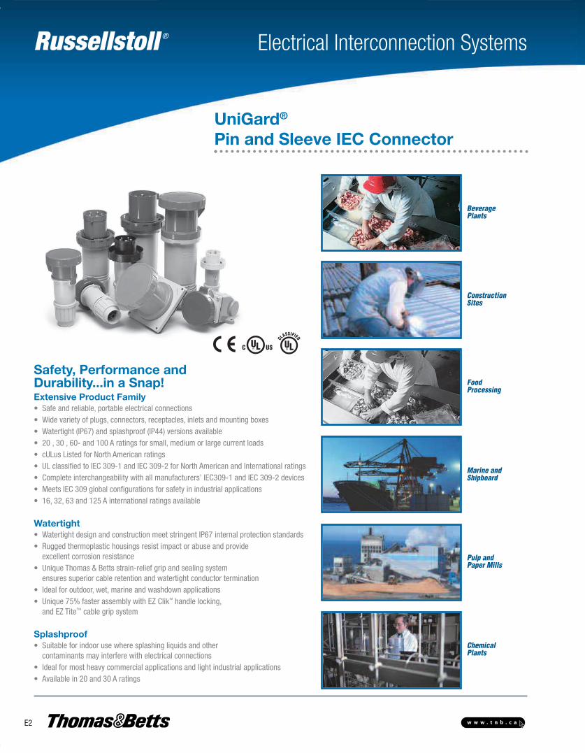
Safety, Performance and Durability...in a Snap!Extensive Product Family• Safe and reliable, portable electrical connections• Wide variety of plugs, connectors, receptacles, inlets and mounting boxes• Watertight (IP67) and splashproof (IP44) versions available• 20 , 30 , 60- and 100 A ratings for small, medium or large current loads• cULus Listed for North American ratings• UL classified to IEC 309-1 and IEC 309-2 for North American and International ratings• Complete interchangeability with all manufacturers’ IEC309-1 and IEC 309-2 devices• Meets IEC 309 global configurations for safety in industrial applications• 16, 32, 63 and 125 A international ratings available
Watertight• Watertight design and construction meet stringent IP67 internal protection standards• Rugged thermoplastic housings resist impact or abuse and provide excellent corrosion resistance• Unique Thomas & Betts strain-relief grip and sealing system ensures superior cable retention and watertight conductor termination• Ideal for outdoor, wet, marine and washdown applications• Unique 75% faster assembly with EZ ClikTM handle locking, and EZ Tite™ cable grip system
Splashproof• Suitable for indoor use where splashing liquids and other contaminants may interfere with electrical connections• Ideal for most heavy commercial applications and light industrial applications• Available in 20 and 30 A ratings
ConstructionSites
FoodProcessing
Marine andShipboard
Pulp andPaper Mills
ChemicalPlants
BeveragePlants
UniGard®
Pin and Sleeve IEC Connector
E-Electrical Interconnection Systems-E.pdf 2 4/2/2013 9:06:50 AM
Russellstoll ®
E3w w w . t n b . c a
Electrical Interconnection Systems
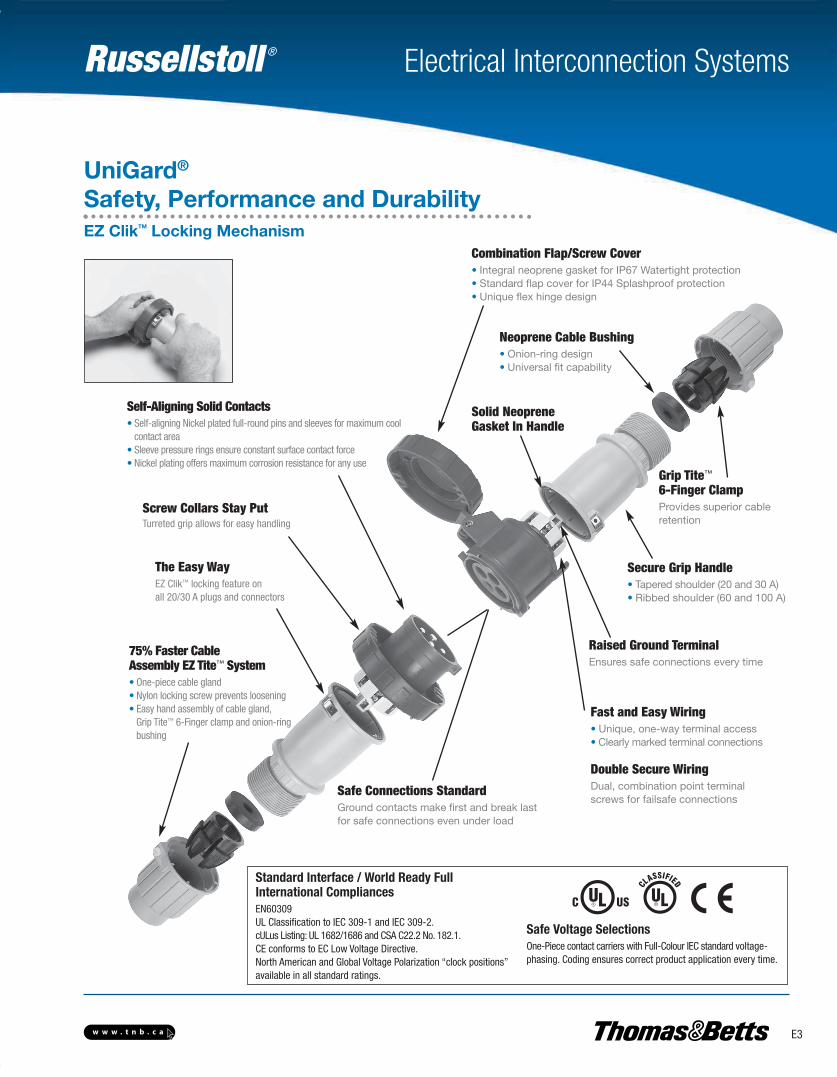
UniGard®
Safety, Performance and Durability
Safe Connections StandardGround contacts make first and break last for safe connections even under load
The Easy WayEZ Clik™ locking feature on all 20/30 A plugs and connectors
Self-Aligning Solid Contacts• Self-aligning Nickel plated full-round pins and sleeves for maximum cool
contact area• Sleeve pressure rings ensure constant surface contact force• Nickel plating offers maximum corrosion resistance for any use
Screw Collars Stay Put Turreted grip allows for easy handling
75% Faster Cable Assembly EZ Tite™ System• One-piece cable gland• Nylon locking screw prevents loosening• Easy hand assembly of cable gland,
Grip Tite™ 6-Finger clamp and onion-ringbushing
Combination Flap/Screw Cover • Integral neoprene gasket for IP67 Watertight protection• Standard flap cover for IP44 Splashproof protection• Unique flex hinge design
Solid NeopreneGasket In Handle
Neoprene Cable Bushing• Onion-ring design• Universal fit capability
Grip Tite™
6-Finger Clamp Provides superior cableretention
Raised Ground Terminal Ensures safe connections every time
Secure Grip Handle • Tapered shoulder (20 and 30 A) • Ribbed shoulder (60 and 100 A)
Fast and Easy Wiring• Unique, one-way terminal access• Clearly marked terminal connections
Double Secure Wiring Dual, combination point terminal screws for failsafe connections
Standard Interface / World Ready FullInternational CompliancesEN60309UL Classification to IEC 309-1 and IEC 309-2.cULus Listing: UL 1682/1686 and CSA C22.2 No. 182.1.CE conforms to EC Low Voltage Directive.North American and Global Voltage Polarization “clock positions”available in all standard ratings.
Safe Voltage SelectionsOne-Piece contact carriers with Full-Colour IEC standard voltage-phasing. Coding ensures correct product application every time.
EZ ClikTM Locking Mechanism
E-Electrical Interconnection Systems-E.pdf 3 4/2/2013 9:06:50 AM
Russellstoll ®
E4 w w w . t n b . c a
Electrical Interconnection Systems
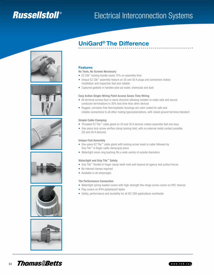
FeaturesNo Tools, No Screws Necessary• EZ ClikTM locking handle saves 75% on assembly time• Unique EZ ClikTM assembly feature on 20 and 30 A plugs and connectors makes installation and inspection fast and reliable• Captured gaskets in handles seal out water, chemicals and dust
Easy Action Single-Wiring Point Access Saves Time Wiring• All terminal screws face in same direction allowing installer to make safe and secure conductor terminations in 30% less time than other devices• Rugged, corrosion-free thermoplastic housings are color-coded for safe and reliable connections to all other mating type/polarizations, with raised ground terminal standard
Simple Cable Clamping• Threaded EZ Tite™ cable gland on 20 and 30 A devices makes assembly fast and easy• One-piece lock screw verifies clamp locking hold, with no external metal contact possible (20 and 30 A devices)
Unique Fast Assembly• One-piece EZ Tite™ cable gland with locking screw loads to cable followed by Grip Tite™ 6-finger cable clamp/grip piece• Watertight onion-ring bushing fits a wide variety of outside diameters
Watertight and Grip Tite™ Safety• Grip Tite™ flexible 6-finger clamp teeth hold well beyond all agency test pullout forces• No internal clamps required• Available in all amperages
The Performance Connection• Watertight spring-loaded covers with high-strength flex-hinge screw covers on IP67 devices• Flap covers on IP44 splashproof styles• Safety, performance and durability for all IEC 309 applications worldwide
UniGard® The Difference
E-Electrical Interconnection Systems-E.pdf 4 4/2/2013 9:06:50 AM
Russellstoll ®
E5w w w . t n b . c a
Electrical Interconnection Systems
Catalogue Numbering System
250/440 to265/460V
60 Hz
440-460V60 Hz
> 50V100 to300 Hz
3Ø120/208
3Ø250V
277V60 Hz
3Ø 600V
3ØY347/600V
125V
100to
130 57/100to
75/130
> 50to
250 DC
38050 Hz
to440
60 Hz
220/38050 Hz
to250/44060 Hz
> 50V300
to 500 Hz
> 50V300
to 500 Hz
> 50V300 to500 Hz
125/250V
5 WIRE 3P+N+G
4 WIRE 3P+G
3 WIRE 2P+G
h
12 1
2
3
4
567
8
9
10
11
380to
415
> 250 DC
480V
3Ø 480V
3Ø 277/480V
250V
380Vto
415V
200/346to
240/415
US
US
US
EUR
EUR
EUR
(spc.) 16a, 5w, 250v, 1h
RECEPTACLE
CONNECTOR
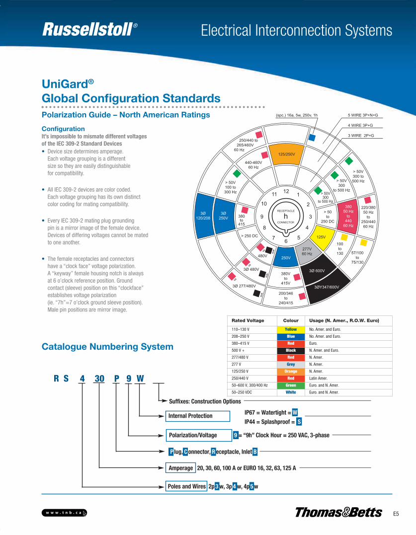
ConfigurationIt’s impossible to mismate different voltages of the IEC 309-2 Standard Devices• Device size determines amperage. Each voltage grouping is a different size so they are easily distinguishable for compatibility.
• All IEC 309-2 devices are color coded. Each voltage grouping has its own distinct color coding for mating compatibility.
• Every IEC 309-2 mating plug grounding pin is a mirror image of the female device. Devices of differing voltages cannot be mated to one another.
• The female receptacles and connectors have a “clock face” voltage polarization. A “keyway” female housing notch is always at 6 o’clock reference position. Ground contact (sleeve) position on this “clockface” establishes voltage polarization (ie. “7h”=7 o’clock ground sleeve position). Male pin positions are mirror image.
Rated Voltage Colour Usage (N. Amer., R.O.W. Euro)
110–130 V Yellow No. Amer. and Euro.
208–250 V Blue No. Amer. and Euro.
380–415 V Red Euro.
500 V + Black N. Amer. and Euro.
277/480 V Red N. Amer.
277 V Grey N. Amer.
125/250 V Orange N. Amer.
250/440 V Red Latin Amer.
50–600 V, 300/400 Hz Green Euro. and N. Amer.
50–250 VDC White Euro. and N. Amer.
Suffixes: Construction Options
Internal Protection IP67 = Watertight = WIP44 = Splashproof = S
Polarization/Voltage 9 = “9h” Clock Hour = 250 VAC, 3-phase
Amperage 20, 30, 60, 100 A or EURO 16, 32, 63, 125 A
P lug, C onnector, R eceptacle, Inlet B
Poles and Wires 2p 3 w, 3p 4 w, 4p 5 w
R S 4
UniGard®
Global Configuration Standards
30 P 9 W
Polarization Guide – North American Ratings
E-Electrical Interconnection Systems-E.pdf 5 4/2/2013 9:06:50 AM
Russellstoll ®
E6 w w w . t n b . c a
Electrical Interconnection Systems
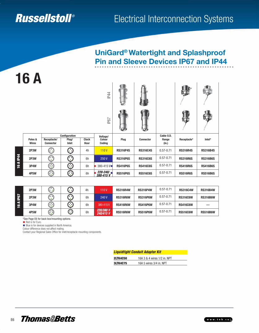
UniGard® Watertight and SplashproofPin and Sleeve Devices IP67 and IP44
Configuration Voltage/ Cable O.D. Poles & Receptacle/ Plug/ Clock Colour Plug Connector Range Receptacle* Inlet* Wires Connector Inlet Hour Coding (in.)
2P3W 4h 110 V RS316P4S RS316C4S 0.57-0.71 RS316R4S RS316B4S
2P3W 6h 250 V RS316P6S RS316C6S 0.57-0.71 RS316R6S RS316B6S
3P4W 6h 380-415 V RS416P6S RS416C6S 0.57-0.71 RS416R6S RS416B6S
4P5W 6h RS516P6S RS516C6S 0.57-0.71 RS516R6S RS516B6S
2P3W 4h 110 V RS316R4W RS316P4W 0.57-0.71 RS316C4W RS316B4W
2P3W 6h 240 V RS316R6W RS316P6W 0.57-0.71 RS316C6W RS316B6W
3P4W 6h 380-415 V RS416R6W RS416P6W 0.57-0.71 RS416C6W —
4P5W 6h RS516R6W RS516P6W 0.57-0.71 RS516C6W RS516B6W
*See Page E6 for back box/mounting options.Red is for Euro.Blue is for devices supplied in North America.
Colour difference does not affect mating.Contact your Regional Sales Office for inlet/receptacle mounting components.
IP67
IP44
16 A
IP44
16 A
IP67
220/380 V240/415 V
220-240/380-415 V
Liquidtight Conduit Adapter Kit
2LTK4C50 16A 3 & 4 wires 1/2 in. NPT
3LTK4C75 16A 5 wires 3/4 in. NPT
16 A
E-Electrical Interconnection Systems-E.pdf 6 4/2/2013 9:06:50 AM
Russellstoll ®
E7w w w . t n b . c a
Electrical Interconnection Systems
Liquidtight Conduit Adapter Kit
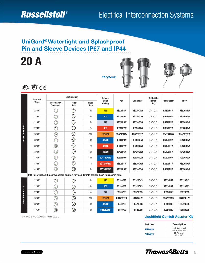
IP67 (shown)
Cat. No. Description
2LTK4C50 20 A 3 wires and4 wires 1/2 in. NPT
3LTK4C75 20 A 5 wires 3/4 in. NPT
* See page E17 for back box/mounting options.
Poles andWires
Configuration Voltage/Color
CodingPlug Connector
Cable O.D.Range(in.)
Receptacle* Inlet*Receptacle/Connector
Plug/Inlet
ClockHour
2P3W 4h 125 RS320P4W RS320C4W 0.57–0.71 RS320R4W RS320B4W
2P3W 6h 250 RS320P6W RS320C6W 0.57–0.71 RS320R6W RS320B6W
2P3W 5h 277 RS320P5W RS320C5W 0.57–0.71 RS320R5W RS320B5W
2P3W 7h 480 RS320P7W RS320C7W 0.57–0.71 RS320R7W RS320B7W
3P4W 12h 125/250 RS420P12W RS420C12W 0.57–0.71 RS420R12W RS420B12W
3P4W 9h 3Ø250 RS420P9W RS420C9W 0.57–0.71 RS420R9W RS420B9W
3P4W 7h 3Ø480 RS420P7W RS420C7W 0.57–0.71 RS420R7W RS420B7W
3P4W 5h 3Ø600 RS420P5W RS420C5W 0.57–0.71 RS420R5W RS420B5W
4P5W 9h 3ØY120/208 RS520P9W RS520C9W 0.57–0.71 RS520R9W RS520B9W
4P5W 7h 3ØY277/480 RS520P7W RS520C7W 0.57–0.71 RS520R7W RS520B7W
4P5W 5h 3ØY347/600 RS520P5W RS520C5W 0.57–0.71 RS520R5W RS520B5W
IP44 Construction: No screw collars on male devices; female devices have flap covers only.
2P3W 4h 125 RS320P4S RS320C4S 0.57–0.71 RS320R4S RS320B4S
2P3W 6h 250 RS320P6S RS320C6S 0.57–0.71 RS320R6S RS320B6S
2P3W 5h 277 RS320P5S RS320C5S 0.57–0.71 RS320R5S RS320B5S
3P4W 12h 125/250 RS420P12S RS420C12S 0.57–0.71 RS420R12S RS420B12S
3P4W 9h 3Ø250 RS420P9S RS420C9S 0.57–0.71 RS420R9S RS420B9S
4P5W 9h 3Ø120/208 RS520P9S RS520C9S 0.57–0.71 RS520R9S RS520B9S
WAT
ERTI
GHT
IP67
SPLA
SHPR
OOF
IP44
20 A
UniGard® Watertight and SplashproofPin and Sleeve Devices IP67 and IP44
E-Electrical Interconnection Systems-E.pdf 7 4/2/2013 9:06:50 AM
Russellstoll ®
E8 w w w . t n b . c a
Electrical Interconnection Systems
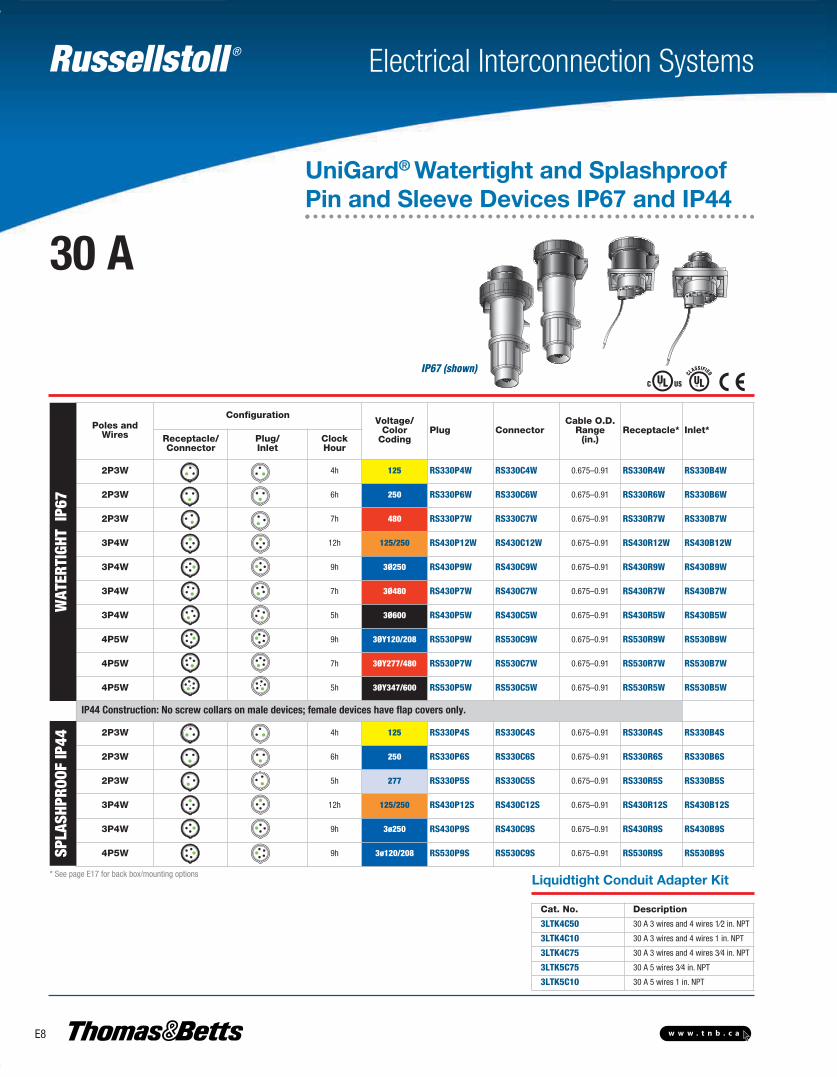
IP67 (shown)
Cat. No. Description
3LTK4C50 30 A 3 wires and 4 wires 1⁄2 in. NPT
3LTK4C10 30 A 3 wires and 4 wires 1 in. NPT
3LTK4C75 30 A 3 wires and 4 wires 3⁄4 in. NPT
3LTK5C75 30 A 5 wires 3⁄4 in. NPT
3LTK5C10 30 A 5 wires 1 in. NPT
Liquidtight Conduit Adapter Kit* See page E17 for back box/mounting options
Poles andWires
ConfigurationVoltage/
ColorCoding
Plug ConnectorCable O.D.
Range(in.)
Receptacle* Inlet*Receptacle/Connector
Plug/Inlet
ClockHour
2P3W 4h 125 RS330P4W RS330C4W 0.675–0.91 RS330R4W RS330B4W
2P3W 6h 250 RS330P6W RS330C6W 0.675–0.91 RS330R6W RS330B6W
2P3W 7h 480 RS330P7W RS330C7W 0.675–0.91 RS330R7W RS330B7W
3P4W 12h 125/250 RS430P12W RS430C12W 0.675–0.91 RS430R12W RS430B12W
3P4W 9h 3Ø250 RS430P9W RS430C9W 0.675–0.91 RS430R9W RS430B9W
3P4W 7h 3Ø480 RS430P7W RS430C7W 0.675–0.91 RS430R7W RS430B7W
3P4W 5h 3Ø600 RS430P5W RS430C5W 0.675–0.91 RS430R5W RS430B5W
4P5W 9h 3ØY120/208 RS530P9W RS530C9W 0.675–0.91 RS530R9W RS530B9W
4P5W 7h 3ØY277/480 RS530P7W RS530C7W 0.675–0.91 RS530R7W RS530B7W
4P5W 5h 3ØY347/600 RS530P5W RS530C5W 0.675–0.91 RS530R5W RS530B5W
IP44 Construction: No screw collars on male devices; female devices have flap covers only.
2P3W 4h 125 RS330P4S RS330C4S 0.675–0.91 RS330R4S RS330B4S
2P3W 6h 250 RS330P6S RS330C6S 0.675–0.91 RS330R6S RS330B6S
2P3W 5h 277 RS330P5S RS330C5S 0.675–0.91 RS330R5S RS330B5S
3P4W 12h 125/250 RS430P12S RS430C12S 0.675–0.91 RS430R12S RS430B12S
3P4W 9h 3ø250 RS430P9S RS430C9S 0.675–0.91 RS430R9S RS430B9S
4P5W 9h 3ø120/208 RS530P9S RS530C9S 0.675–0.91 RS530R9S RS530B9SSPLA
SHPR
OOF
IP44
WAT
ERTI
GHT
IP67
UniGard® Watertight and SplashproofPin and Sleeve Devices IP67 and IP44
30 A
E-Electrical Interconnection Systems-E.pdf 8 4/2/2013 9:06:50 AM
Russellstoll ®
E9w w w . t n b . c a
Electrical Interconnection Systems
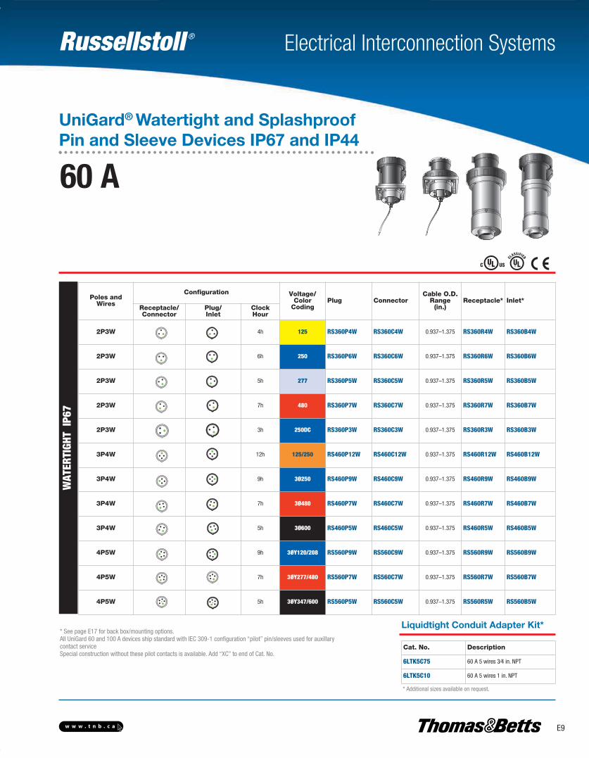
Liquidtight Conduit Adapter Kit*
Cat. No. Description
6LTK5C75 60 A 5 wires 3⁄4 in. NPT
6LTK5C10 60 A 5 wires 1 in. NPT
* See page E17 for back box/mounting options.All UniGard 60 and 100 A devices ship standard with IEC 309-1 configuration “pilot” pin/sleeves used for auxillarycontact serviceSpecial construction without these pilot contacts is available. Add “XC” to end of Cat. No.
* Additional sizes available on request.
Poles andWires
Configuration Voltage/Color
CodingPlug Connector
Cable O.D.Range
(in.)Receptacle* Inlet*
Receptacle/Connector
Plug/Inlet
ClockHour
2P3W 4h 125 RS360P4W RS360C4W 0.937–1.375 RS360R4W RS360B4W
2P3W 6h 250 RS360P6W RS360C6W 0.937–1.375 RS360R6W RS360B6W
2P3W 5h 277 RS360P5W RS360C5W 0.937–1.375 RS360R5W RS360B5W
2P3W 7h 480 RS360P7W RS360C7W 0.937–1.375 RS360R7W RS360B7W
2P3W 3h 250DC RS360P3W RS360C3W 0.937–1.375 RS360R3W RS360B3W
3P4W 12h 125/250 RS460P12W RS460C12W 0.937–1.375 RS460R12W RS460B12W
3P4W 9h 3Ø250 RS460P9W RS460C9W 0.937–1.375 RS460R9W RS460B9W
3P4W 7h 3Ø480 RS460P7W RS460C7W 0.937–1.375 RS460R7W RS460B7W
3P4W 5h 3Ø600 RS460P5W RS460C5W 0.937–1.375 RS460R5W RS460B5W
4P5W 9h 3ØY120/208 RS560P9W RS560C9W 0.937–1.375 RS560R9W RS560B9W
4P5W 7h 3ØY277/480 RS560P7W RS560C7W 0.937–1.375 RS560R7W RS560B7W
4P5W 5h 3ØY347/600 RS560P5W RS560C5W 0.937–1.375 RS560R5W RS560B5W
UniGard® Watertight and SplashproofPin and Sleeve Devices IP67 and IP44
60 A
WAT
ERTI
GHT
IP67
E-Electrical Interconnection Systems-E.pdf 9 4/2/2013 9:06:51 AM

Russellstoll ®
E10 w w w . t n b . c a
Electrical Interconnection Systems
Poles/Wires
Configuration Voltage/Color
CodingPlug Connector
Cable O.D.Range
(in.)Receptacle* Inlet*
Receptacle/Connector
Plug/Inlet
ClockHour
2P3W** 6h 250 RS3100P6W RS3100C6W 1.2650–1.790 RS3100R6W RS3100B6W
2P3W** 7h 480 RS3100P7W RS3100C7W 1.2650–1.790 RS3100R7W RS3100B7W
3P4W 12h 125/250 RS4100P12W RS4100C12W 1.2650–1.790 RS4100R12W RS4100B12W
3P4W 9h 3Ø250 RS4100P9W RS4100C9W 1.2650–1.790 RS4100R9W RS4100B9W
3P4W 7h 3Ø480 RS4100P7W RS4100C7W 1.2650–1.790 RS4100R7W RS4100B7W
3P4W 5h 3Ø600 RS4100P5W RS4100C5W 1.2650–1.790 RS4100R5W RS4100B5W
4P5W 9h 3ØY120/208 RS5100P9W RS5100C9W 1.2650–1.790 RS5100R9W RS5100B9W
4P5W 7h 3ØY277/480 RS5100P7W RS5100C7W 1.2650–1.790 RS5100R7W RS5100B7W
4P5W 5h 3ØY347/600 RS5100P5W RS5100C5W 1.2650–1.790 RS5100R5W RS5100B5W
* See page E17 for back box/mounting options.** Alternate vendor-supplied item; construction features will vary from specs in this catalog. Full IEC approval and
mating guaranteed. Contact your Regional Sales Office for inlet/receptacle mounting components. All UniGard 60- and 100-A devices ship standard with IEC 309-1 configuration “pilot” pin/sleeves used for auxillarycontact service.Special construction without these pilot contacts is available. (Add “XC” to end of Cat. No.)
Liquidtight Conduit Adapter Kit
* For 4-wire and 5-wire plugs and connectors only. Contact yourRegional Sales Office for 3-wire plug and connector conduitadapters. 100 A 3-wire plugs and connectors use PG48backhandle thread.
Cat. No. Description
10LTK5C10* 100 A 4 wires, 5 wires 1 in. NPT
10LTK5C125* 100 A 4 wires, 5 wires 1-1⁄4 in. NPT
10LTK5C150* 100 A 4 wires, 5 wires 1-1⁄2 in. NPT
WAT
ERTI
GHT
IP67
UniGard® Watertight and SplashproofPin and Sleeve Devices IP67 and IP44
100 A
E-Electrical Interconnection Systems-E.pdf 10 4/2/2013 9:06:51 AM
Russellstoll ®
E11w w w . t n b . c a
Electrical Interconnection Systems
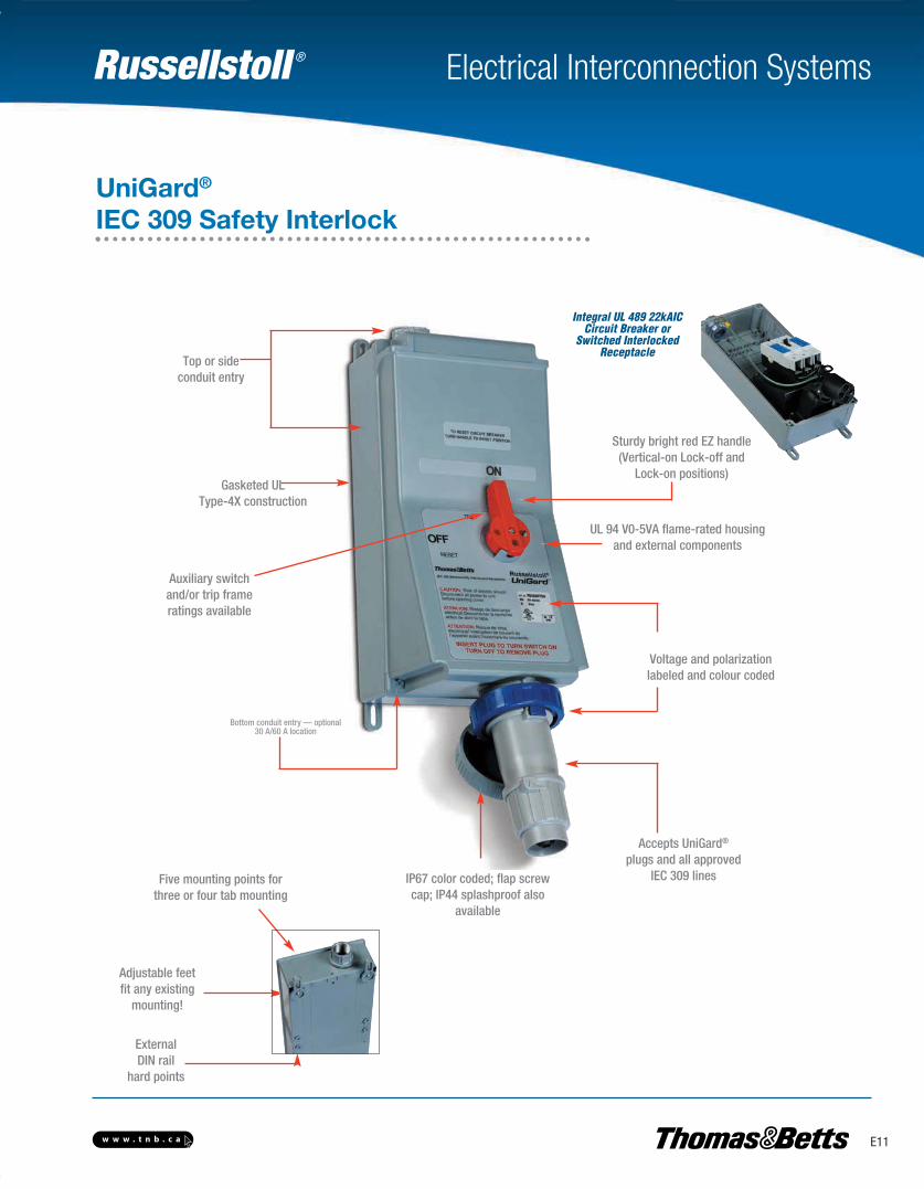
Adjustable feetfit any existing
mounting!
ExternalDIN rail
hard points
Integral UL 489 22kAICCircuit Breaker or
Switched InterlockedReceptacle
Top or sideconduit entry
Bottom conduit entry — optional30 A/60 A location
Five mounting points forthree or four tab mounting
UL 94 V0-5VA flame-rated housingand external components
Auxiliary switchand/or trip frameratings available
IP67 color coded; flap screwcap; IP44 splashproof also
available
Voltage and polarizationlabeled and colour coded
Accepts UniGard®
plugs and all approvedIEC 309 lines
Gasketed ULType-4X construction
UniGard®
IEC 309 Safety Interlock
Sturdy bright red EZ handle(Vertical-on Lock-off and
Lock-on positions)
E-Electrical Interconnection Systems-E.pdf 11 4/2/2013 9:06:51 AM

Russellstoll ®
E12 w w w . t n b . c a
Electrical Interconnection Systems
• Top, side and bottom entry• Industry standard entry sizes
• Circuit breaker integrated interlock mechanism• UL 489 Listed 22kAIC protection• Alternate trip ratings available• Auxiliary switch option
The Only True Circuit BreakerInterlocked IEC 309 Receptacle (Outlet)
• “W” suffixes (UL Type 4X construction)• Rugged thermoplastic housings resist impact or abuse
and provide excellent corrosion resistance• Rugged V0-5VA flameproof housings• Ideal for outdoor, wet, marine and washdown applications• Unique industry-first circuit breaker interlock• US: 20, 30, 60 and 100 A sizes• International: 16, 32, 63 and 125 A sizes
Watertight — IP67
• “S” suffixes (NEMA 3R construction)• Suitable for indoor use where splashing liquids
and other contaminants may interfere with electrical connections
• Ideal for most heavy commercial applicationsand light industrial applications
• US 20, 30 and 60 A ratings• International 16, 32 and 63 A ratings
Splashproof — IP44
• Rugged UL Listed switch• Proven performance components• Through 600 VAC 4P5W plus auxiliary
contacts capable
Mount It Anywhere• Swivel 3- or 4-point feet variable
footprint for flexible mounting• Fits in web of 8 in. I-beams
Top and Bottom Top Side Entry
20/30 A 60/100 A All
UniGard® IEC 309 Safety Interlock
Protection and Safetyin Power Delivery• Red vertical “ON’’ indication• Lock “ON’’ and Lock “OFF” positions• Branch circuit load and operation protection or switched-only version (shown)
Switched-Only VersionWire It Up, Sideways or Down
E-Electrical Interconnection Systems-E.pdf 12 4/2/2013 9:06:51 AM

Russellstoll ®
E13w w w . t n b . c a
Electrical Interconnection Systems
UniGard® IEC 309 Safety Interlock
Specifications for Any New or Replacement Project
16/20 A, 30/32 A, 60/63 A and 100/125 A International and U.S. Ratings in all Standard Voltage Polarizations:
Contact T&B for other special polarizations.
Range Colour Code Usage (N. Amer., R.O.W. Euro) 2P3W 3P4W 4P5
110–130 V Yellow N. Amer./Euro 4h 4h —
208–250 V Blue N. Amer./Euro 6h 9h 9h
380–415 V Red Euro 9h 6h/3h (spec) 6h
500 V + Black N. Amer./Euro — 5h 5h
277/480 V Red N. Amer. (Black, Euro) 7h 7h 7h
277 V Gray N. Amer. 5h — —
125/250 V Orange N. Amer. — 12h —
250/440 V Red Latin Amer./N. Amer. — 11h 11h/3h
to 600 V, to 400 Hz Green N. Amer./Euro 2h 2h 2h
RS 4 30 9 W
Internal Protection
Amperage 20, 30, 60, 100 A or EURO 16, 32, 63, 125 A
2 options available
MI
Integral Circuit Breaker (UL 231 and UL 489) Power Outlet> (replaces all fused-switched competitor “FMIR” or “MIF” Series) (US amperage only)
Rotary Switched (UL 508 and UL 98) Manual Motor Controller Outlet> (replaces all switched-only competitor “MI” or “MIR” Series) (all amperages)
Brandprefix- or -
“blank”
Device Type See above
MT
Suffixes: Construction Options
Poles and Wires 2p3w, 3p4w, 4p5w
IP67 = Watertight = WIP44 = Splashproof = S
Polarization/Voltage 9 = “9h” Clock Hour = 250 VAC, 3-phase
E-Electrical Interconnection Systems-E.pdf 13 4/2/2013 9:06:51 AM
Russellstoll ®
E14 w w w . t n b . c a
Electrical Interconnection Systems
H
G
D
E
F
I
E
GD
H
F
I
5.1 (129) 7.2 (183)
A
B9.3 (237)
C
A
B
7.2 (183)
14.6 (370)
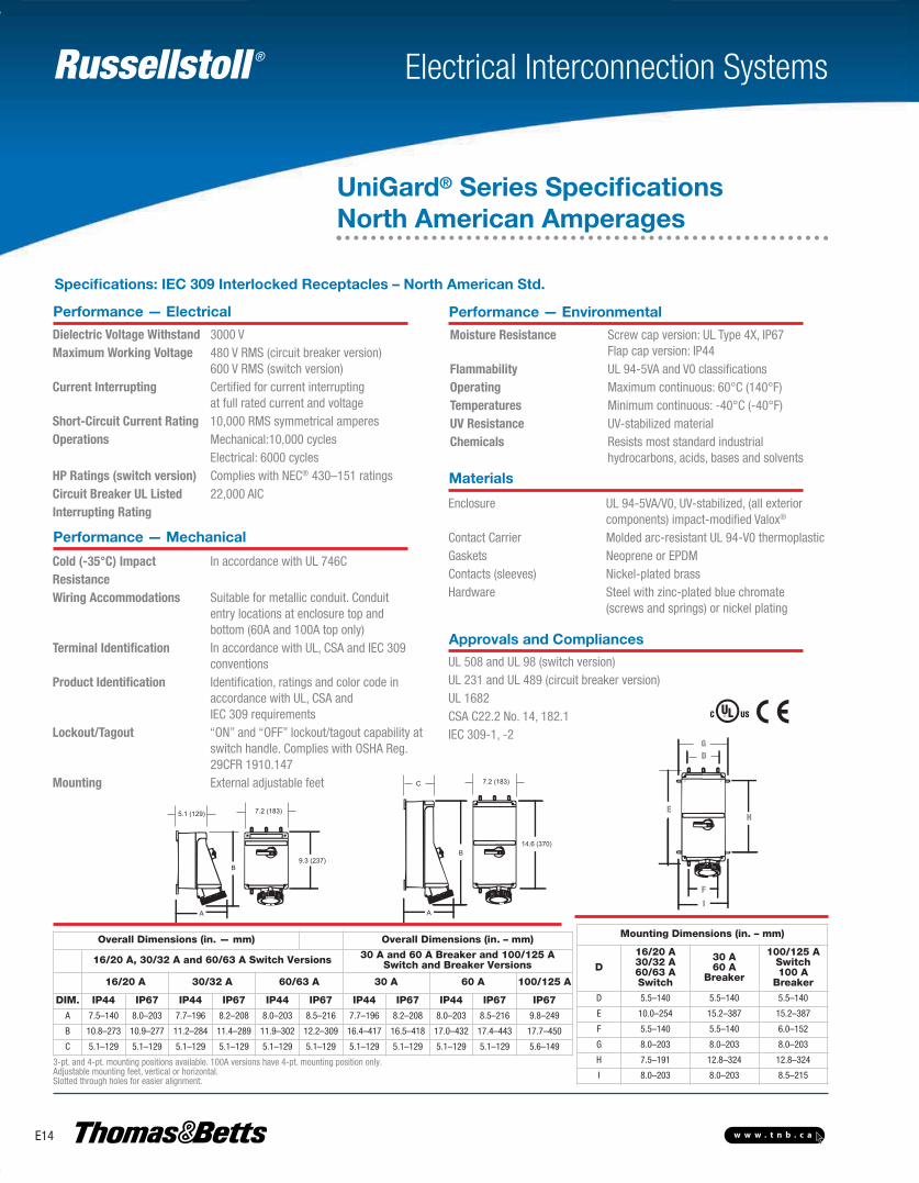
UniGard® Series SpecificationsNorth American Amperages
Performance — Electrical
Dielectric Voltage Withstand 3000 VMaximum Working Voltage 480 V RMS (circuit breaker version)
600 V RMS (switch version)Current Interrupting Certified for current interrupting
at full rated current and voltageShort-Circuit Current Rating 10,000 RMS symmetrical amperesOperations Mechanical:10,000 cycles Electrical: 6000 cyclesHP Ratings (switch version) Complies with NEC® 430–151 ratingsCircuit Breaker UL Listed 22,000 AICInterrupting Rating
Performance — Environmental
Moisture Resistance Screw cap version: UL Type 4X, IP67Flap cap version: IP44
Flammability UL 94-5VA and V0 classificationsOperating Maximum continuous: 60°C (140°F)Temperatures Minimum continuous: -40°C (-40°F)UV Resistance UV-stabilized materialChemicals Resists most standard industrial
hydrocarbons, acids, bases and solvents
Materials
Enclosure UL 94-5VA/V0, UV-stabilized, (all exteriorcomponents) impact-modified Valox®
Contact Carrier Molded arc-resistant UL 94-V0 thermoplasticGaskets Neoprene or EPDMContacts (sleeves) Nickel-plated brassHardware Steel with zinc-plated blue chromate
(screws and springs) or nickel plating
Approvals and Compliances
UL 508 and UL 98 (switch version)UL 231 and UL 489 (circuit breaker version)UL 1682CSA C22.2 No. 14, 182.1IEC 309-1, -2
Performance — Mechanical
Cold (-35°C) Impact In accordance with UL 746CResistanceWiring Accommodations Suitable for metallic conduit. Conduit
entry locations at enclosure top andbottom (60A and 100A top only)
Terminal Identification In accordance with UL, CSA and IEC 309conventions
Product Identification Identification, ratings and color code in accordance with UL, CSA and IEC 309 requirements
Lockout/Tagout “ON” and “OFF” lockout/tagout capability atswitch handle. Complies with OSHA Reg.29CFR 1910.147
Mounting External adjustable feet
Overall Dimensions (in. — mm) Overall Dimensions (in. – mm)
16/20 A, 30/32 A and 60/63 A Switch Versions 30 A and 60 A Breaker and 100/125 ASwitch and Breaker Versions
16/20 A 30/32 A 60/63 A 30 A 60 A 100/125 A
DIM. IP44 IP67 IP44 IP67 IP44 IP67 IP44 IP67 IP44 IP67 IP67
A 7.5–140 8.0–203 7.7–196 8.2–208 8.0–203 8.5–216 7.7–196 8.2–208 8.0–203 8.5–216 9.8–249
B 10.8–273 10.9–277 11.2–284 11.4–289 11.9–302 12.2–309 16.4–417 16.5–418 17.0–432 17.4–443 17.7–450
C 5.1–129 5.1–129 5.1–129 5.1–129 5.1–129 5.1–129 5.1–129 5.1–129 5.1–129 5.1–129 5.6–149
Mounting Dimensions (in. – mm)
D
16/20 A30/32 A60/63 ASwitch
30 A60 A
Breaker
100/125 ASwitch100 A
Breaker
D 5.5–140 5.5–140 5.5–140
E 10.0–254 15.2–387 15.2–387
F 5.5–140 5.5–140 6.0–152
G 8.0–203 8.0–203 8.0–203
H 7.5–191 12.8–324 12.8–324
I 8.0–203 8.0–203 8.5–2153-pt. and 4-pt. mounting positions available. 100A versions have 4-pt. mounting position only.Adjustable mounting feet, vertical or horizontal.Slotted through holes for easier alignment.
Specifications: IEC 309 Interlocked Receptacles – North American Std.
E-Electrical Interconnection Systems-E.pdf 14 4/2/2013 9:06:51 AM

Russellstoll ®
E15w w w . t n b . c a
Electrical Interconnection Systems
B
A
CB
CA
B
C A
D
Inlet IP44 16/20A and 30/32A
B
CI
A
D Receptacle IP44 16/20A and 30/32A
F
E
øG
øH CLEARANCE HOLE
øHClearanceHole
B
B
A
B
AC
D
D
C
B
AF
E
ØG
ØHClearance
Hole
I
Receptacle IP4416/20 A and 30/32 A
Inlet IP4416/20 A and 30/32 A
AC
C Connector IP44Plug IP44
Inlet IP44
Receptacle IP44
A B C Cord Grip Range
Cat. No. in. mm in. mm in. mm in. mm
16/20A 2P3W 2.26 58 6.20 157 4.76 121 0.570–0.710 14–18
16/20A 3P4W 2.52 64 6.47 164 5.04 128 0.570–0.710 14–18
16/20A 4P5W 2.85 73 7.02 178 5.58 142 0.570–0.710 14–18
30/32A 2P3W 2.85 73 7.37 187 5.58 142 0.675–0.910 17–23
30/32A 3P4W 2.85 73 7.37 187 5.58 142 0.675–0.910 17–23
30/32A 4P5W 3.13 80 8.15 207 6.36 162 0.675–0.910 17–23
Cat. No. A B C Cord Grip Range
in. mm in. mm in. mm in. mm
16/20A 2P3W 2.18 55 6.53 166 3.07 78 0.570–0.710 14–18
16/20A 3P4W 2.43 62 6.83 173 3.33 85 0.570–0.710 14–18
16/20A 4P5W 2.81 71 7.41 188 3.79 96 0.570–0.710 14–18
30/32A 2P3W 2.81 71 781 198 3.79 96 0.675–0.910 17–23
30/32A 3P4W 2.81 71 781 188 3.79 96 0 675–0.910 17–23
30/32A 4P5W 3.09 79 8.62 219 4.17 106 0.675–0.910 17–23
Cat. No.A B C D E F G H
in. mm in. mm in. mm in. mm in. mm in. mm in. mm in. mm
16/20A 2P3W 2.26 58 1.96 50 4.50 114 0.75 19 3.87 98 3.87 98 2.38 60 0.282 7.2
16/20A 3P4W 2.52 64 1.96 50 4.50 114 0.75 19 3.87 98 3.87 98 2.38 60 0.282 7.2
16/20A 4P5W 2.85 73 1.96 50 4.50 114 0.75 19 3.87 98 3.87 98 2.38 60 0.282 7.2
30/32A 2P3W 2.85 73 2.32 59 4.50 114 1.32 34 3.87 98 3.87 98 2.38 60 0.282 7.2
30/32A 3P4W 2.85 73 2.32 59 4.50 114 1.32 34 3.87 98 3.87 98 2.38 60 0.282 7.2
30/32A 4P5W 3.13 80 2.32 59 4.50 114 1.32 34 3.87 98 3.87 98 2.38 60 0.282 7.2
UniGard® Series IP44 Dimensions
E-Electrical Interconnection Systems-E.pdf 15 4/2/2013 9:06:51 AM
Russellstoll ®
E16 w w w . t n b . c a
Electrical Interconnection Systems
B
D
C A
B
AC
D
B
D
C AC
B
A
D
F
E
øG
øH CLEARANCEHOLE
øHClearanceHole
E
FøG
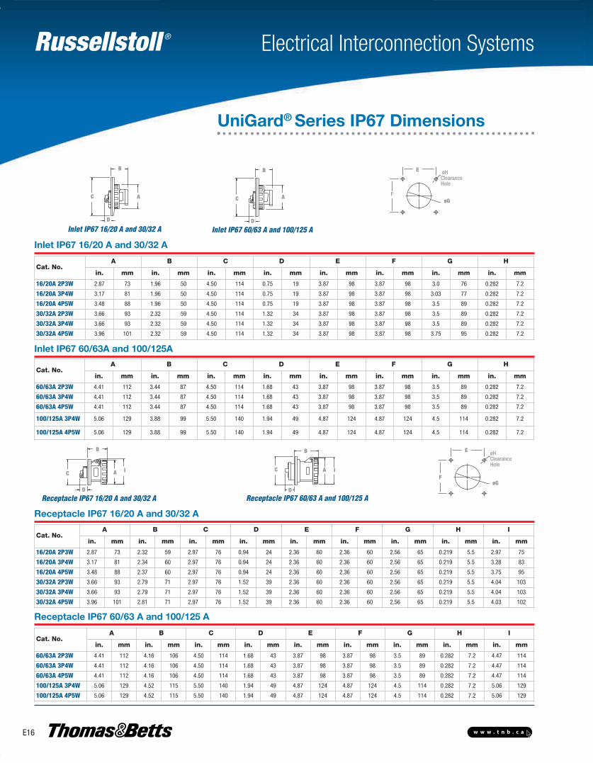
Cat. No.A B C D E F G H
in. mm in. mm in. mm in. mm in. mm in. mm in. mm in. mm
16/20A 2P3W 2.87 73 1.96 50 4.50 114 0.75 19 3.87 98 3.87 98 3.0 76 0.282 7.2
16/20A 3P4W 3.17 81 1.96 50 4.50 114 0.75 19 3.87 98 3.87 98 3.03 77 0.282 7.2
16/20A 4P5W 3.48 88 1.96 50 4.50 114 0.75 19 3.87 98 3.87 98 3.5 89 0.282 7.2
30/32A 2P3W 3.66 93 2.32 59 4.50 114 1.32 34 3.87 98 3.87 98 3.5 89 0.282 7.2
30/32A 3P4W 3.66 93 2.32 59 4.50 114 1.32 34 3.87 98 3.87 98 3.5 89 0.282 7.2
30/32A 4P5W 3.96 101 2.32 59 4.50 114 1.32 34 3.87 98 3.87 98 3.75 95 0.282 7.2
Cat. No.A B C D E F G H
in. mm in. mm in. mm in. mm in. mm in. mm in. mm in. mm
60/63A 2P3W 4.41 112 3.44 87 4.50 114 1.68 43 3.87 98 3.87 98 3.5 89 0.282 7.2
60/63A 3P4W 4.41 112 3.44 87 4.50 114 1.68 43 3.87 98 3.87 98 3.5 89 0.282 7.2
60/63A 4P5W 4.41 112 3.44 87 4.50 114 1.68 43 3.87 98 3.87 98 3.5 89 0.282 7.2
100/125A 3P4W 5.06 129 3.88 99 5.50 140 1.94 49 4.87 124 4.87 124 4.5 114 0.282 7.2
100/125A 4P5W 5.06 129 3.88 99 5.50 140 1.94 49 4.87 124 4.87 124 4.5 114 0.282 7.2
Cat. No.A B C D E F G H I
in. mm in. mm in. mm in. mm in. mm in. mm in. mm in. mm in. mm
16/20A 2P3W 2.87 73 2.32 59 2.97 76 0.94 24 2.36 60 2.36 60 2.56 65 0.219 5.5 2.97 75
16/20A 3P4W 3.17 81 2.34 60 2.97 76 0.94 24 2.36 60 2.36 60 2.56 65 0.219 5.5 3.28 83
16/20A 4P5W 3.48 88 2.37 60 2.97 76 0.94 24 2.36 60 2.36 60 2.56 65 0.219 5.5 3.75 95
30/32A 2P3W 3.66 93 2.79 71 2.97 76 1.52 39 2.36 60 2.36 60 2.56 65 0.219 5.5 4.04 103
30/32A 3P4W 3.66 93 2.79 71 2.97 76 1.52 39 2.36 60 2.36 60 2.56 65 0.219 5.5 4.04 103
30/32A 4P5W 3.96 101 2.81 71 2.97 76 1.52 39 2.36 60 2.36 60 2.56 65 0.219 5.5 4.03 102
Cat. No.A B C D E F G H I
in. mm in. mm in. mm in. mm in. mm in. mm in. mm in. mm in. mm
60/63A 2P3W 4.41 112 4.16 106 4.50 114 1.68 43 3.87 98 3.87 98 3.5 89 0.282 7.2 4.47 114
60/63A 3P4W 4.41 112 4.16 106 4.50 114 1.68 43 3.87 98 3.87 98 3.5 89 0.282 7.2 4.47 114
60/63A 4P5W 4.41 112 4.16 106 4.50 114 1.68 43 3.87 98 3.87 98 3.5 89 0.282 7.2 4.47 114
100/125A 3P4W 5.06 129 4.52 115 5.50 140 1.94 49 4.87 124 4.87 124 4.5 114 0.282 7.2 5.06 129
100/125A 4P5W 5.06 129 4.52 115 5.50 140 1.94 49 4.87 124 4.87 124 4.5 114 0.282 7.2 5.06 129
Receptacle IP67 60/63 A and 100/125 A
Receptacle IP67 16/20 A and 30/32 A
B
C
D
A I
D
C
B
A I
B
IAC
DD
C
B
A IF
E
øG
øH CLEARANCEHOLE
øHClearanceHole
E
FøG
Inlet IP67 60/63A and 100/125A
Inlet IP67 16/20 A and 30/32 A
UniGard® Series IP67 Dimensions
Receptacle IP67 16/20 A and 30/32 A Receptacle IP67 60/63 A and 100/125 A
Inlet IP67 60/63 A and 100/125 AInlet IP67 16/20 A and 30/32 A
E-Electrical Interconnection Systems-E.pdf 16 4/2/2013 9:06:52 AM
Russellstoll ®
E17w w w . t n b . c a
Electrical Interconnection Systems
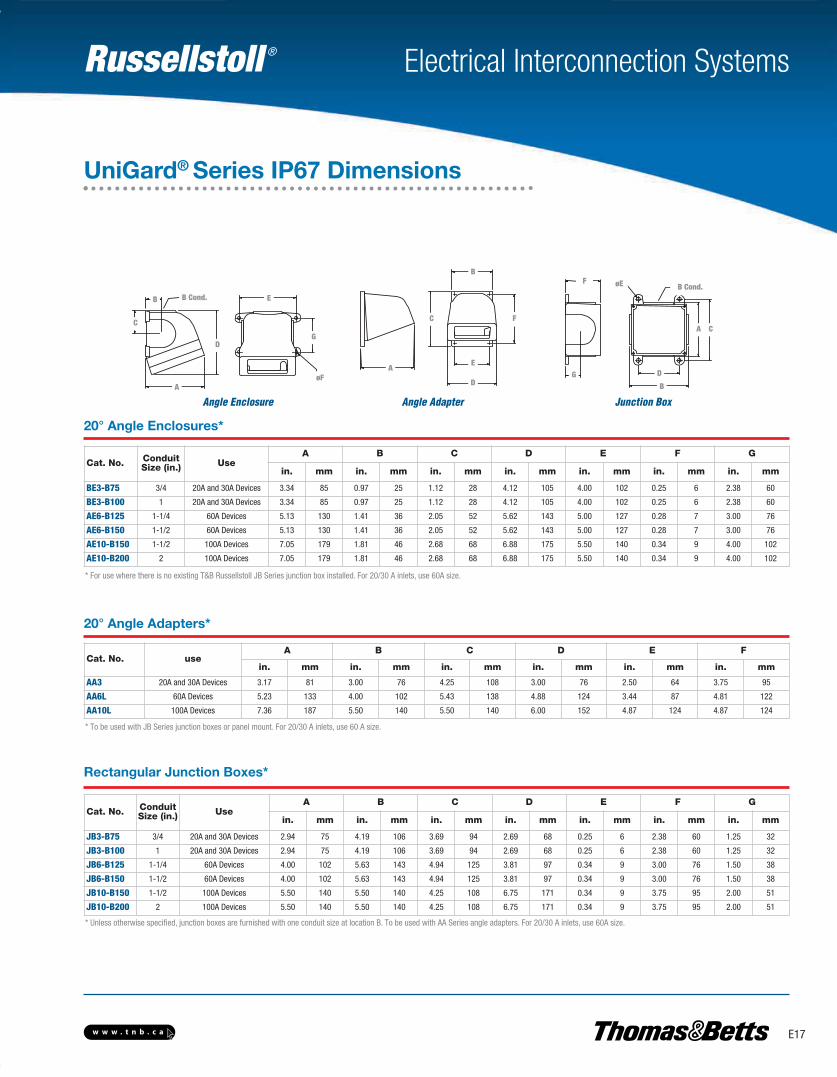
20° Angle Enclosures*
20° Angle Adapters*
Rectangular Junction Boxes*
B
CA
øE
D
F
G
B cond.
Junction Box
G
A C
D
B
F øE B Cond.
B
C
A E
D
F
Angle Adapter
B
E
F
D
A
C
B
C
A
E
D
øF
G
B cond.
Angle Enclosure
B E
G
øF
D
A
C
B Cond.
Cat. No. ConduitSize (in.) Use
A B C D E F G
in. mm in. mm in. mm in. mm in. mm in. mm in. mm
BE3-B75 3/4 20A and 30A Devices 3.34 85 0.97 25 1.12 28 4.12 105 4.00 102 0.25 6 2.38 60
BE3-B100 1 20A and 30A Devices 3.34 85 0.97 25 1.12 28 4.12 105 4.00 102 0.25 6 2.38 60
AE6-B125 1-1/4 60A Devices 5.13 130 1.41 36 2.05 52 5.62 143 5.00 127 0.28 7 3.00 76
AE6-B150 1-1/2 60A Devices 5.13 130 1.41 36 2.05 52 5.62 143 5.00 127 0.28 7 3.00 76
AE10-B150 1-1/2 100A Devices 7.05 179 1.81 46 2.68 68 6.88 175 5.50 140 0.34 9 4.00 102
AE10-B200 2 100A Devices 7.05 179 1.81 46 2.68 68 6.88 175 5.50 140 0.34 9 4.00 102
Cat. No. useA B C D E F
in. mm in. mm in. mm in. mm in. mm in. mm
AA3 20A and 30A Devices 3.17 81 3.00 76 4.25 108 3.00 76 2.50 64 3.75 95
AA6L 60A Devices 5.23 133 4.00 102 5.43 138 4.88 124 3.44 87 4.81 122
AA10L 100A Devices 7.36 187 5.50 140 5.50 140 6.00 152 4.87 124 4.87 124
Cat. No. ConduitSize (in.) Use
A B C D E F G
in. mm in. mm in. mm in. mm in. mm in. mm in. mm
JB3-B75 3/4 20A and 30A Devices 2.94 75 4.19 106 3.69 94 2.69 68 0.25 6 2.38 60 1.25 32
JB3-B100 1 20A and 30A Devices 2.94 75 4.19 106 3.69 94 2.69 68 0.25 6 2.38 60 1.25 32
JB6-B125 1-1/4 60A Devices 4.00 102 5.63 143 4.94 125 3.81 97 0.34 9 3.00 76 1.50 38
JB6-B150 1-1/2 60A Devices 4.00 102 5.63 143 4.94 125 3.81 97 0.34 9 3.00 76 1.50 38
JB10-B150 1-1/2 100A Devices 5.50 140 5.50 140 4.25 108 6.75 171 0.34 9 3.75 95 2.00 51
JB10-B200 2 100A Devices 5.50 140 5.50 140 4.25 108 6.75 171 0.34 9 3.75 95 2.00 51
* For use where there is no existing T&B Russellstoll JB Series junction box installed. For 20/30 A inlets, use 60A size.
* To be used with JB Series junction boxes or panel mount. For 20/30 A inlets, use 60 A size.
* Unless otherwise specified, junction boxes are furnished with one conduit size at location B. To be used with AA Series angle adapters. For 20/30 A inlets, use 60A size.
UniGard® Series IP67 Dimensions
E-Electrical Interconnection Systems-E.pdf 17 4/2/2013 9:06:52 AM
Russellstoll ®
E18 w w w . t n b . c a
Dura-Gard®
Nonmetallic Waterproof Connections
Electrical Interconnection Systems
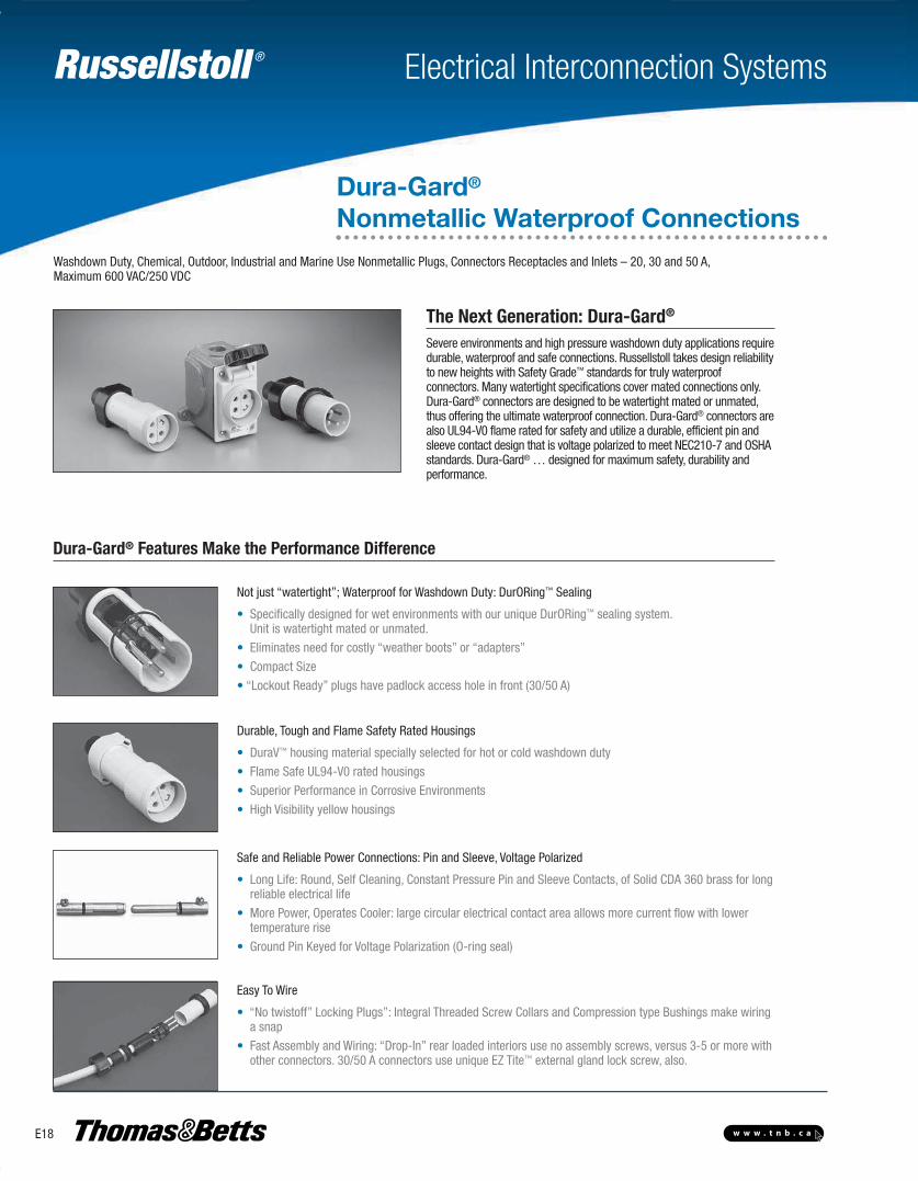
Dura-Gard® Features Make the Performance Difference
Not just “watertight”; Waterproof for Washdown Duty: DurORing™ Sealing
• Specifically designed for wet environments with our unique DurORing™ sealing system. Unit is watertight mated or unmated.
• Eliminates need for costly “weather boots” or “adapters”
• Compact Size
• “Lockout Ready” plugs have padlock access hole in front (30/50 A)
Durable, Tough and Flame Safety Rated Housings
• DuraV™ housing material specially selected for hot or cold washdown duty
• Flame Safe UL94-V0 rated housings
• Superior Performance in Corrosive Environments
• High Visibility yellow housings
Safe and Reliable Power Connections: Pin and Sleeve, Voltage Polarized
• Long Life: Round, Self Cleaning, Constant Pressure Pin and Sleeve Contacts, of Solid CDA 360 brass for longreliable electrical life
• More Power, Operates Cooler: large circular electrical contact area allows more current flow with lowertemperature rise
• Ground Pin Keyed for Voltage Polarization (O-ring seal)
Easy To Wire
• “No twistoff” Locking Plugs”: Integral Threaded Screw Collars and Compression type Bushings make wiringa snap
• Fast Assembly and Wiring: “Drop-In” rear loaded interiors use no assembly screws, versus 3-5 or more withother connectors. 30/50 A connectors use unique EZ Tite™ external gland lock screw, also.
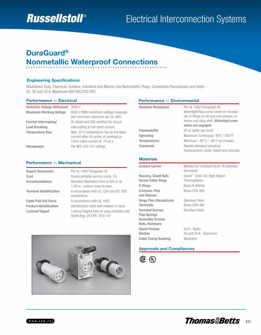
Washdown Duty, Chemical, Outdoor, Industrial and Marine Use Nonmetallic Plugs, Connectors Receptacles and Inlets – 20, 30 and 50 A,Maximum 600 VAC/250 VDC
The Next Generation: Dura-Gard®
Severe environments and high pressure washdown duty applications requiredurable, waterproof and safe connection s. Russellstoll takes design reliabilityto new heights with Safety Grade™ standards for truly waterproof connectors. Many watertight specifications cover mated connections only.Dura-Gard® connectors are designed to be watertight mated or unmated,thus offering the ultimate waterproof connection. Dura-Gard® connectors arealso UL94-V0 flame rated for safety and utilize a durable, efficient pin andsleeve contact design that is voltage polarized to meet NEC210-7 and OSHAstandards. Dura-Gard® … designed for maximum safety, durability and performance.
E-Electrical Interconnection Systems-E.pdf 18 4/2/2013 9:06:52 AM
Russellstoll ®
E19w w w . t n b . c a
Electrical Interconnection Systems
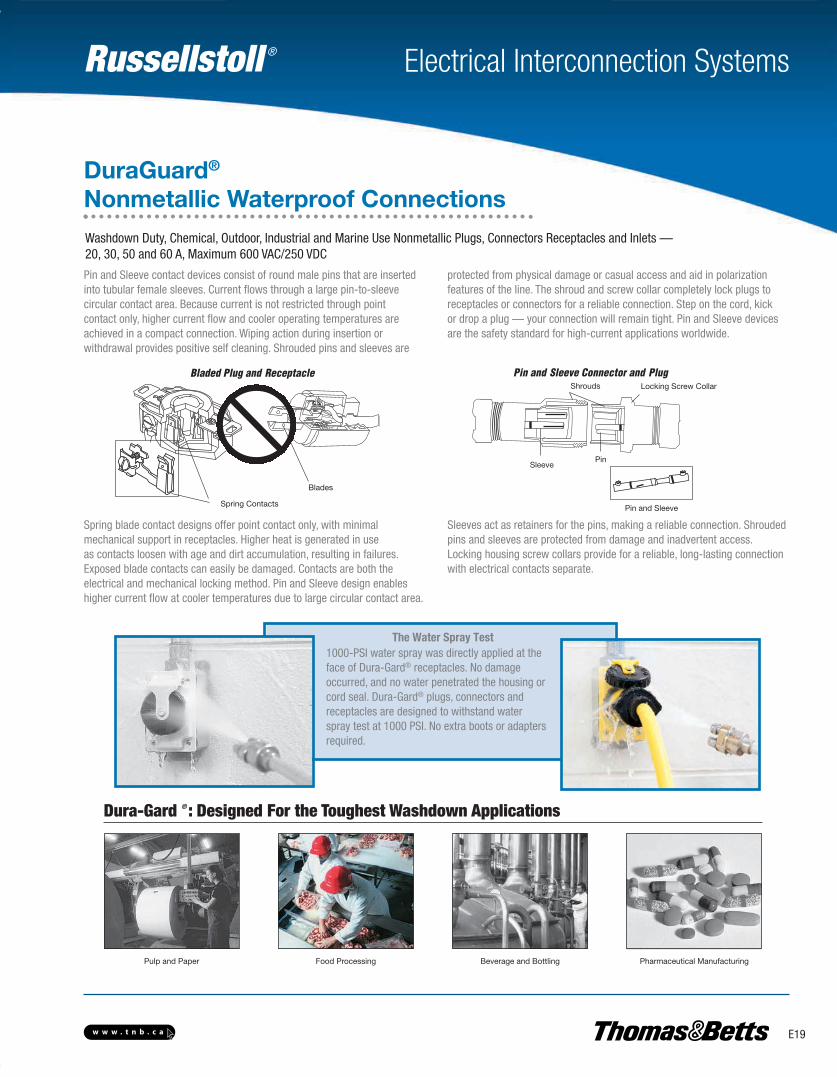
Pin and Sleeve contact devices consist of round male pins that are insertedinto tubular female sleeves. Current flows through a large pin-to-sleevecircular contact area. Because current is not restricted through point contact only, higher current flow and cooler operating temperatures areachieved in a compact connection. Wiping action during insertion or withdrawal provides positive self cleaning. Shrouded pins and sleeves are
protected from physical damage or casual access and aid in polarizationfeatures of the line. The shroud and screw collar completely lock plugs to receptacles or connectors for a reliable connection. Step on the cord, kick or drop a plug — your connection will remain tight. Pin and Sleeve devicesare the safety standard for high-current applications worldwide.
Spring blade contact designs offer point contact only, with minimal mechanical support in receptacles. Higher heat is generated in useas contacts loosen with age and dirt accumulation, resulting in failures.Exposed blade contacts can easily be damaged. Contacts are both the electrical and mechanical locking method. Pin and Sleeve design enableshigher current flow at cooler temperatures due to large circular contact area.
Sleeves act as retainers for the pins, making a reliable connection. Shroudedpins and sleeves are protected from damage and inadvertent access. Locking housing screw collars provide for a reliable, long-lasting connectionwith electrical contacts separate.
Washdown Duty, Chemical, Outdoor, Industrial and Marine Use Nonmetallic Plugs, Connectors Receptacles and Inlets —20, 30, 50 and 60 A, Maximum 600 VAC/250 VDC
DuraGuard®
Nonmetallic Waterproof Connections
Pin and Sleeve
Bladed Plug and Receptacle Pin and Sleeve Connector and Plug
Spring Contacts
Blades
Shrouds
SleevePin
Locking Screw Collar
The Water Spray Test1000-PSI water spray was directly applied at theface of Dura-Gard® receptacles. No damageoccurred, and no water penetrated the housing orcord seal. Dura-Gard® plugs, connectors andreceptacles are designed to withstand waterspray test at 1000 PSI. No extra boots or adaptersrequired.
Dura-Gard ® : Designed For the Toughest Washdown Applications
Pulp and Paper Pharmaceutical ManufacturingFood Processing Beverage and Bottling
E-Electrical Interconnection Systems-E.pdf 19 4/2/2013 9:06:52 AM
Russellstoll ®
E20 w w w . t n b . c a
Electrical Interconnection Systems
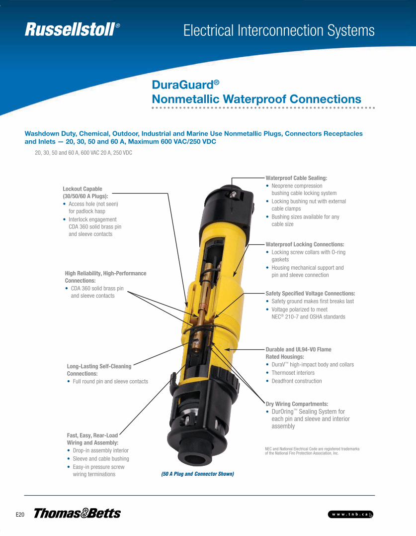
20, 30, 50 and 60 A, 600 VAC 20 A, 250 VDC
Safety Specified Voltage Connections:• Safety ground makes first breaks last• Voltage polarized to meet NEC® 210-7 and OSHA standards
High Reliability, High-PerformanceConnections:• CDA 360 solid brass pin and sleeve contacts
Long-Lasting Self-CleaningConnections:• Full round pin and sleeve contacts
Fast, Easy, Rear-LoadWiring and Assembly:• Drop-in assembly interior• Sleeve and cable bushing• Easy-in pressure screw wiring terminations
Waterproof Cable Sealing:• Neoprene compression
bushing cable locking system• Locking bushing nut with external cable clamps• Bushing sizes available for any cable size
Durable and UL94-V0 FlameRated Housings:• DuraV™ high-impact body and collars• Thermoset interiors• Deadfront construction
Waterproof Locking Connections: • Locking screw collars with O-ring gaskets• Housing mechanical support and pin and sleeve connection
Dry Wiring Compartments:• DurOring™ Sealing System for each pin and sleeve and interior assembly
(50 A Plug and Connector Shown)
Lockout Capable(30/50/60 A Plugs):• Access hole (not seen) for padlock hasp• Interlock engagement CDA 360 solid brass pin and sleeve contacts
NEC and National Electrical Code are registered trademarksof the National Fire Protection Association, Inc.
Washdown Duty, Chemical, Outdoor, Industrial and Marine Use Nonmetallic Plugs, Connectors Receptaclesand Inlets — 20, 30, 50 and 60 A, Maximum 600 VAC/250 VDC
DuraGuard®
Nonmetallic Waterproof Connections
E-Electrical Interconnection Systems-E.pdf 20 4/2/2013 9:06:52 AM
Russellstoll ®
E21w w w . t n b . c a
Electrical Interconnection Systems
Washdown Duty, Chemical, Outdoor, Industrial and Marine Use Nonmetallic Plugs, Connectors Receptacles and Inlets – 20, 30 and 50 A, Maximum 600 VAC/250 VDC
DuraGuard®
Nonmetallic Waterproof Connections
Performance — Electrical
Dielectric Voltage Withstand 3000 VMaximum Working Voltage 6000 V RMS (minimum voltage creepage
and minimum clearance per UL 840)Current Interrupting/ UL listed and CSA certified for circuit Load Breaking interrupting at full rated current.Temperature Rise Max. 30°C temperature rise at full rated
current after 50 cycles of overload at 150% rated current at .75-pf.s
Horsepower Per NEC 430-151 ratings
Performance — Environmental
Moisture Resistance Per UL 1682 Paragraph 49.Watertight/flap screw cover on recepta-cle, O-Rings on all pins and sleeves, in-teriors and plug shell. Watertight evenwhen not engaged.
Flammability V0 or better per UL94Operating Maximum Continuous: 95ºC / 203°FTemperatures Minimum: -40°C / -40°F w/o impactChemicals Resists standard industrial
hydrocarbons, acids, bases and solvents.
Materials
Contact Carrier Molded arc-resistant UL94-V0 phenolic thermoset
Housing, Gland Nuts DuraV™ UL94-V0, High ImpactScrew Collar Rings ThermoplasticO-Rings Buna-N (Nitrile)Contacts: Pins Brass CDA 360and SleevesHinge Pins (Receptacle) Stainless SteelTerminals Brass CDA 360Terminal Screws Stainless SteelFlap SpringsAssembly ScrewsNuts, HardwareGland Friction 20 A - NylonWasher 30 and 50 A - AluminumCable Clamp Bushing Neoprene
Approvals and Compliances
Impact Resistance Per UL 1682 Paragraph 34Cord Round portable service cords. 10Accommodations Standard diameters from 0.405 in. to
1.00 in., custom sizes to spec.Terminal Identification In accordance with UL, CSA and IEC 309
conventionsCable Pull-Out Force In accordance with UL 1682Product Identification Identification label and molded in nameLockout/Tagout Lockout/Tagout hole on plug complies with
OSHA Reg. 29 CFR 1910.147
Engineering Specifications
Performance — Mechanical
E-Electrical Interconnection Systems-E.pdf 21 4/2/2013 9:06:52 AM

Russellstoll ®
E22 w w w . t n b . c a
Electrical Interconnection Systems
DuraGuard®
Nonmetallic Waterproof Connections
Std. I.D. Safety Bushing: Voltage Polarization Plug/ Female A Polarization (Receptacle) Male Plug Female Connector Conn. Receptacle Female Plug Male Receptacle ■ ■ □
125 VAC 9P23U1 9C23U1 9R23U1W
250 VAC 9P23U2 9C23U2 9R23U2W
2P3W 277 VAC 9P23U3 9C23U3 9R23U3W
20 A 480 VAC 9P23U4 9C23U4 9R23U4W
600 VAC 9P23U5 9C23U5 9R23U5W
thru 600 VAC/250 VDC 9P23U0 9C23U0 9R23U0W ■ □ 125 VAC 9P33U1 9C33U1 9R33U1W 9F33U1 9B33U1F
250 VAC 9P33U2 9C33U2 9R33U2W 9F33U2 9B33U2F
2P3W 277 VAC 9P33U3 9C33U3 9R33U3W 9F33U3 9B33U3F
30 A 480 VAC 9P33U4 9C33U4 9R33U4W 9F33U4 9B33U4F
600 VAC 9P33U5 9C33U5 9R33U5W 9F33U5 9B33U5F
thru 600 VAC/3P3W 9P33U0 9C33U0 9R33U0W 9F33UØ 9B33UØF
125 VAC 9P53U1 9C53U1 9R53U1W 9F53U1 9B53U1F
250 VAC 9P53U2 9C53U2 9R53U2W 9F53U2 9B53U2F
2P3W 277 VAC 9P53U3 9C53U3 9R53U3W 9F53U3 9B53U3F
50 A 480 VAC 9P53U4 9C53U4 9R53U4W 9F53U4 9B53U4F
600 VAC 9P53U5 9C53U5 9R53U5W 9F53U5 9B53U5F
thru 600 VAC/3P3W 9P53U0 9C53U0 9R53U0W 9F53UØ 9B53UØF
125/250 VAC 9P24U1 9C24U1 9R24U1W
250- 3ø VAC 9P24U2 9C24U2 9R24U2W
3P4W 480 3ø VAC 9P24U4 9C24U4 9R24U4W
20 A 600 3ø VAC 9P24U5 9C24U5 9R24U5W
thru 600 VAC / 250 VDC 9P24U0 9C24U0 9R24U0W
125/250 VAC 9P34U1 9C34U1 9R34U1W 9F34U1 9B34U1F
250 3ø VAC 9P34U2 9C34U2 9R34U2W 9F34U2 9B34U2F
3P4W 480 3ø VAC 9P34U4 9C34U4 9R34U4W 9F34U4 9B34U4F
30 A 600 3ø VAC 9P34U5 9C34U5 9R34U5W 9F34U5 9B34U5F
thru 600 VAC/4P4W 9P34U0 9C34U0 9R34U0W 9F34UØ 9B34UØF
125/250 VAC 9P54U1 9C54U1 9R54U1W 9F54U1 9B54U1F
250 3ø VAC 9P54U2 9C54U2 9R54U2W 9F54U2 9B54U2F
3P4W 480 3ø VAC 9P54U4 9C54U4 9R54U4W 9F54U4 9B54U4F
50 A 600 3ø VAC 9P54U5 9C54U5 9R54U5W 9F54U5 9B54U5F
thru 600 VAC/4P4W 9P54U0 9C54U0 9R54U0W 9F54UØ 9B54UØF
Standard0.625
For OptionalSizes
See p. E24
Standard0.700
For OptionalSizes
See p. E24
Standard0.925
For OptionalSizes
See p. E24
Standard0.625
For OptionalSizes
See p. E24
Standard0.750
For OptionalSizes
See p. E24
Standard0.925
For OptionalSizes
See p. E24
■ Add Suffix - / xxxx for bushing I.D.(E24) or conduit adapterassembled.
□ “W” suffix is watertight “F” suffixfor splashproof spring flap cover.
* Consult your Regional Sales Office.
E-Electrical Interconnection Systems-E.pdf 22 4/2/2013 9:06:52 AM

Russellstoll ®
E23w w w . t n b . c a
Electrical Interconnection Systems
DuraGuard®
Nonmetallic Waterproof Connections
A A* B C* Max AWG Terminal Ø in./mm
20 A
Inches 3.87 2.16 2.75 12 0.140/0.0055
mm 98.3 54.9 69.9
30 A
Inches 5.385 2.38 4.16 8 0.235/0.0092
mm 136.6 60.5 105.7
50 A
Inches 5.75 2.38 4.16 6 0.235/0.0092
mm 146.1 60.5 105.7
A
B
C
D
E
Plugs and Female Plugs (30/50 A only) Connectors
* Dimensions will vary slightly with assembly
Receptacles and Male Receptacles (inlets – 30/50 A only)
A F G H I J K M Max. AWG
Terminal Ø in/mm
20 A
Inches 4.14 3.25 2.66 1.88 1.49 2.26 3.17 12 0.140/0.0055
mm 105.2 82.6 67.6 47.8 37.8 57.4 80.5
30 A Inches 4.14 3.25 2.66 1.88 2.44 2.71 4.12
8 0.235/0.0092 mm 105.2 82.6 67.6 47.8 62.0 68.8 104.6
50 A
Inches 4.14 3.25 2.66 1.88 2.44 2.71 4.12 6 0.235/0.0092
mm 105.2 82.6 67.6 47.8 62.0 68.8 104.6
Screw cover shown. Flap cover also available; no dimensional changes
Washdown Duty, Chemical, Outdoor, Industrial and Marine Use Nonmetallic Plugs, Connectors Receptacles and Inlets – 20, 30 and 50 A, Maximum 600 VAC/250 VDC
A D E Max AWG Terminal Ø in./mm
20 A
Inches 4.75 1.88 12 .140/.0055
mm 120.7 47.8
30 A
Inches 6.25 2.13 8 .235/.0092
mm 158.8 54.1
50 A
Inches 6.25 2.13 6 .235/.0092
mm 158.8 54.1
E-Electrical Interconnection Systems-E.pdf 23 4/2/2013 9:06:52 AM
Russellstoll ®
E24 w w w . t n b . c a
Electrical Interconnection Systems
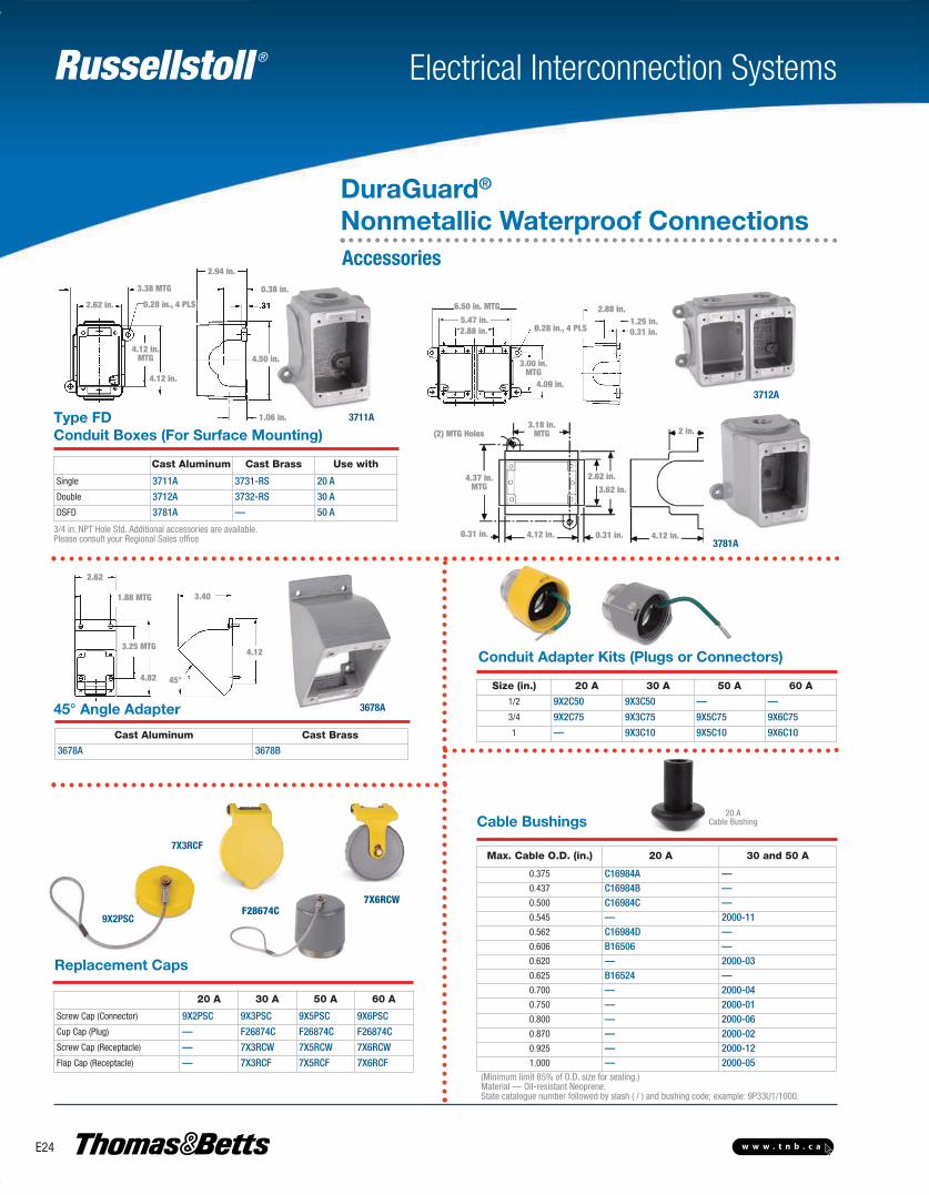
3/4 in. NPT Hole Std. Additional accessories are available. Please consult your Regional Sales office
(Minimum limit 85% of O.D. size for sealing.)Material — Oil-resistant Neoprene.State catalogue number followed by slash ( / ) and bushing code; example: 9P33U1/1000.
Conduit Boxes (For Surface Mounting)
Replacement Caps
20 ACable BushingCable Bushings
Conduit Adapter Kits (Plugs or Connectors)
3712A
9X2PSC
7X6RCW
45° Angle Adapter
F28674C
7X3RCF
Type FD
2.62
4.82
4.12
3.40
45°
1.88 MTG
3.25 MTG
6.50 in. MTG
3.00 in.MTG
Ø.28 in., 4 PLS5.47 in.
4.09 in.
2.88 in.
2.88 in.1.25 in.0.31 in.
Cast Aluminum Cast Brass Use with
Single 3711A 3731-RS 20 A
Double 3712A 3732-RS 30 A
DSFD 3781A — 50 A
Cast Aluminum Cast Brass
3678A 3678B
Max. Cable O.D. (in.) 20 A 30 and 50 A
0.375 C16984A —0.437 C16984B —0.500 C16984C —0.545 — 2000-110.562 C16984D —0.606 B16506 —0.620 — 2000-030.625 B16524 —0.700 — 2000-040.750 — 2000-010.800 — 2000-060.870 — 2000-020.925 — 2000-121.000 — 2000-05
Size (in.) 20 A 30 A 50 A 60 A
1/2 9X2C50 9X3C50 — —
3/4 9X2C75 9X3C75 9X5C75 9X6C75
1 — 9X3C10 9X5C10 9X6C10
20 A 30 A 50 A 60 A
Screw Cap (Connector) 9X2PSC 9X3PSC 9X5PSC 9X6PSC
Cup Cap (Plug) — F26874C F26874C F26874C
Screw Cap (Receptacle) — 7X3RCW 7X5RCW 7X6RCW
Flap Cap (Receptacle) — 7X3RCF 7X5RCF 7X6RCF
3678A
3711A
(2) MTG Holes3.18 in.
MTG
4.37 in.MTG
2.62 in.3.62 in.
0.31 in. 0.31 in.4.12 in. 4.12 in.
2 in.
3781A
0.28 in., 4 PLS2.62 in.
0.38 in.
4.50 in.
1.06 in.
4.12 in.
4.12 in.MTG
DuraGuard®
Nonmetallic Waterproof ConnectionsAccessories
3.38 MTG
2.94 in.
E-Electrical Interconnection Systems-E.pdf 24 4/2/2013 9:06:52 AM
Russellstoll ®
E25w w w . t n b . c a
Electrical Interconnection Systems
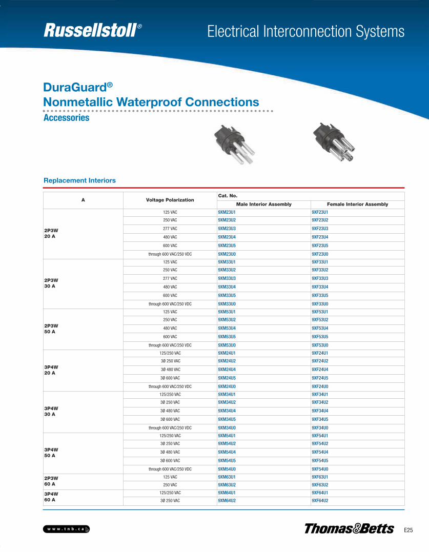
A Voltage PolarizationCat. No.
Male Interior Assembly Female Interior Assembly
2P3W20 A
125 VAC 9XM23U1 9XF23U1
250 VAC 9XM23U2 9XF23U2
277 VAC 9XM23U3 9XF23U3
480 VAC 9XM23U4 9XF23U4
600 VAC 9XM23U5 9XF23U5
through 600 VAC/250 VDC 9XM23U0 9XF23U0
2P3W30 A
125 VAC 9XM33U1 9XF33U1
250 VAC 9XM33U2 9XF33U2
277 VAC 9XM33U3 9XF33U3
480 VAC 9XM33U4 9XF33U4
600 VAC 9XM33U5 9XF33U5
through 600 VAC/250 VDC 9XM33U0 9XF33U0
2P3W50 A
125 VAC 9XM53U1 9XF53U1
250 VAC 9XM53U2 9XF53U2
480 VAC 9XM53U4 9XF53U4
600 VAC 9XM53U5 9XF53U5
through 600 VAC/250 VDC 9XM53U0 9XF53U0
3P4W20 A
125/250 VAC 9XM24U1 9XF24U1
3Ø 250 VAC 9XM24U2 9XF24U2
3Ø 480 VAC 9XM24U4 9XF24U4
3Ø 600 VAC 9XM24U5 9XF24U5
through 600 VAC/250 VDC 9XM24U0 9XF24U0
3P4W30 A
125/250 VAC 9XM34U1 9XF34U1
3Ø 250 VAC 9XM34U2 9XF34U2
3Ø 480 VAC 9XM34U4 9XF34U4
3Ø 600 VAC 9XM34U5 9XF34U5
through 600 VAC/250 VDC 9XM34U0 9XF34U0
3P4W50 A
125/250 VAC 9XM54U1 9XF54U1
3Ø 250 VAC 9XM54U2 9XF54U2
3Ø 480 VAC 9XM54U4 9XF54U4
3Ø 600 VAC 9XM54U5 9XF54U5
through 600 VAC/250 VDC 9XM54U0 9XF54U0
2P3W60 A
125 VAC 9XM63U1 9XF63U1
250 VAC 9XM63U2 9XF63U2
3P4W60 A
125/250 VAC 9XM64U1 9XF64U1
3Ø 250 VAC 9XM64U2 9XF64U2
Replacement Interiors
DuraGuard®
Nonmetallic Waterproof ConnectionsAccessories
E-Electrical Interconnection Systems-E.pdf 25 4/2/2013 9:06:52 AM
Russellstoll ®
E26 w w w . t n b . c a
Electrical Interconnection Systems
DuraGuard®
Nonmetallic Waterproof Connections
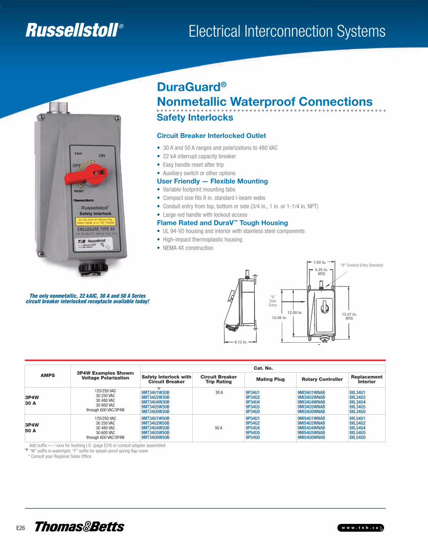
• 30 A and 50 A ranges and polarizations to 480 VAC• 22 kA interrupt capacity breaker• Easy handle reset after trip• Auxiliary switch or other optionsUser Friendly — Flexible Mounting• Variable footprint mounting tabs• Compact size fits 8 in. standard I-beam webs• Conduit entry from top, bottom or side (3/4 in., 1 in. or 1-1/4 in. NPT)• Large red handle with lockout accessFlame Rated and DuraV™ Tough Housing• UL 94-V0 housing and interior with stainless steel components• High-impact thermoplastic housing• NEMA 4X construction
Circuit Breaker Interlocked Outlet
8.13 in.
13.47 in.MTG
5.25 in.MTG
7.00 in.
13.46 in.12.00 in.
“A”SideEntry
“B” Conduit Entry Standard
The only nonmetallic, 22 kAIC, 30 A and 50 A Seriescircuit breaker interlocked receptacle available today!
AMPS 3P4W Examples Shown:Voltage Polarization
Cat. No.
Safety Interlock with Circuit Breaker
Circuit BreakerTrip Rating Mating Plug Rotary Controller Replacement
Interior
3P4W30 A
125/250 VAC30 250 VAC30 480 VAC30 600 VAC
through 600 VAC/3P4W
9MT34U1W30B9MT34U2W30B9MT34U4W30B9MT34U5W30B9MT34U0W30B
30 A 9P34U19P34U29P34U49P34U59P34U0
9MI34U1WNAB9MI34U2WNAB9MI34U4WNAB9MI34U5WNAB9MI34U0WNAB
9XL34U19XL34U29XL34U49XL34U59XL34U0
3P4W50 A
125/250 VAC30 250 VAC30 480 VAC30 600 VAC
through 600 VAC/3P4W
9MT34U1W50B9MT34U2W50B9MT34U4W50B9MT34U5W50B9MT34U0W50B
50 A
9P54U19P54U29P54U49P54U59P54U0
9MI54U1WNAB9MI54U2WNAB9MI54U4WNAB9MI54U5WNAB9MI54U0WNAB
9XL54U19XL54U29XL54U49XL54U59XL54U0
Add suffix — / xxxx for bushing I.D. (page E24) or conduit adapter assembled“W” suffix is watertight; “F” suffix for splash-proof spring flap cover* Consult your Regional Sales Office
Safety Interlocks
E-Electrical Interconnection Systems-E.pdf 26 4/2/2013 9:06:52 AM

Russellstoll ®
E27w w w . t n b . c a
Electrical Interconnection Systems
DuraGuard®
Nonmetallic Waterproof ConnectionsSafety Interlocks Engineering SpecificationsWashdown Duty, Chemical, Outdoor, Industrial and Marine Use Nonmetallic Plugs, Connectors Receptacles and Inlets – 20, 30 and 50 A,Maximum 600 VAC/250 VDC
Performance — Electrical
Dielectric Voltage Withstand 3000 VMaximum Working Voltage 480 V RMS (minimum creepage distance
and minimum clearance per UL 840) (usingcircuit breaker)
Current Interrupting/ UL listed and CSA certified for Load circuit Load Breaking interrupting at full rated current.Temperature Rise Max. 30°C temperature rise at full rated
current after 50 cycles of overload at 150%rated current at 0.75-pf.
Horsepower Exceeds NEC 430-151 ratings (Circuit Breaker)
Performance — Environmental
Moisture Resistance Per UL 1682 Paragraph 49.Watertight/flap screw cover on receptacle, O-Rings on all pins andsleeves, interiors and plug shell. Watertight even when not engaged.(Screw cover closed / locked)
Flammability V0 or better per UL94Operating Maximum Continuous: 95ºC / 203°FTemperatures Minimum: -40°C / -40°F w/o impact
(note: per circuit breaker trip curves atelevated temps.)
Chemicals Resists standard industrial hydrocarbons, acids, bases and solvents.
UV Resistance UV stabilized material
Materials
Contact Carrier Molded arc resistant UL94-V0 thermoset material
Housing, Gland Nuts DuraV™ UL94-V0, High ImpactScrew Collar Rings ThermoplasticO-Rings Buna-N (Nitrile)Contacts: Pins Brass CDA 360and SleevesHinge Pins (Receptacle) Stainless SteelTerminals Brass CDA 360Terminal Screws Stainless SteelFlap SpringsAssembly ScrewsNuts, Hardware
Approvals and Compliances
Impact Resistance Per UL 1682 Paragraph 34Wire Accommodations Conduit Entries at top, side and bottom.
.750" NPT top entry standardTerminal Identification In accordance with UL 1682 IdentificationPlug Pull-Out Force In accordance with UL 1682Product Identification Identification labelLockout/Tagout Lockout/Tagout hole on plug complies with
OSHA Reg. 29 CFR 1910.147
Performance — Mechanical
E-Electrical Interconnection Systems-E.pdf 27 4/2/2013 9:06:52 AM

Russellstoll ®
E28 w w w . t n b . c a
Electrical Interconnection Systems
Safety• Circuit-interrupting up to 30 A, 250 VAC (20 A, 600 VAC)• Factory-polarized interiors permit mating of same voltage/ same type devices through configured ground pins and housing features• Shell grounding by means of ground strap integral with ground contact for assured assembly safety
Durability• Constructed of copper-free cast aluminum (brass construction also available)• Optional conduit adapters, strain reliefs and cable bushings available (modified catalogue number construction)• Nonmetallic versions of most metallic plugs and receptacles also available (see Dura-Gard®, pages E18–E27)
Performance• Precision-made, self-aligning and self-wiping contacts• Devices available in watertight and weathertight versions• Solderless binding screw terminals for convenient wiring (20 A, 2P3W devices have set-screw pressure terminals)
The FS/FD™ general-purpose interconnection system is designed for lower-amperage marine andrough service applications with rugged die-cast aluminum housings and epoxy powder-coated finishes. Interlocked receptacles add branch circuit-protected outlet capability and base receptaclesfit existing Russellstoll® FS, FD and DSFD single and multi-gang back boxes. Its versatility and watertight features make it ideal for washdown industrial and light marine applications.
FS/FD™ Metallic ConnectionsOverview
E-Electrical Interconnection Systems-E.pdf 28 4/2/2013 9:06:52 AM
Russellstoll ®
E29w w w . t n b . c a
Electrical Interconnection Systems
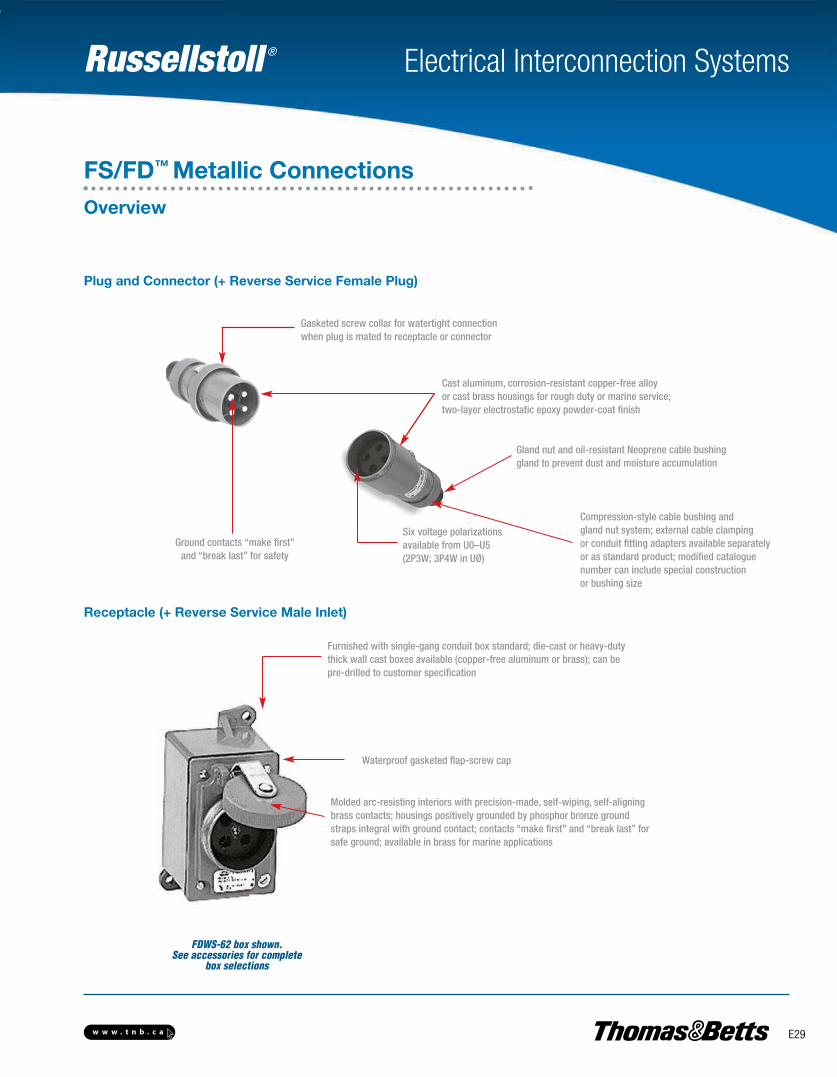
Plug and Connector (+ Reverse Service Female Plug)
Receptacle (+ Reverse Service Male Inlet)
Gasketed screw collar for watertight connectionwhen plug is mated to receptacle or connector
Cast aluminum, corrosion-resistant copper-free alloyor cast brass housings for rough duty or marine service;two-layer electrostatic epoxy powder-coat finish
Gland nut and oil-resistant Neoprene cable bushinggland to prevent dust and moisture accumulation
Compression-style cable bushing andgland nut system; external cable clampingor conduit fitting adapters available separatelyor as standard product; modified catalogue number can include special constructionor bushing size
Six voltage polarizationsavailable from U0–U5(2P3W; 3P4W in UØ)
Ground contacts “make first” and “break last” for safety
Furnished with single-gang conduit box standard; die-cast or heavy-dutythick wall cast boxes available (copper-free aluminum or brass); can bepre-drilled to customer specification
Waterproof gasketed flap-screw cap
Molded arc-resisting interiors with precision-made, self-wiping, self-aligningbrass contacts; housings positively grounded by phosphor bronze groundstraps integral with ground contact; contacts “make first” and “break last” forsafe ground; available in brass for marine applications
FDWS-62 box shown.See accessories for complete
box selections
FS/FD™ Metallic ConnectionsOverview
E-Electrical Interconnection Systems-E.pdf 29 4/2/2013 9:06:52 AM
Russellstoll ®
E30 w w w . t n b . c a
Electrical Interconnection Systems
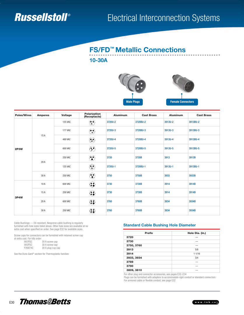
FS/FD™ Metallic Connections10-30A
Male Plugs Female Connectors
Cable Bushings — Oil-resistant, Neoprene cable bushing is regularlyfurnished with hole sizes listed above. Other hole sizes are available at noextra cost when specified on order. See page E32 for available sizes.
Screw caps for connectors can be furnished with retained screw capat extra cost. For kits order:
9X2PSC 20 A screw cap9X3PSC 30 A screw capF26874C 30 A plug cup cap
See the Dura-Gard® section for Thermoplastic families
Prefix Hole Dia. (in.)
3720 —
3730 —
3750, 3760 —
3913 5/8
3914 1-1/16
3933, 3934 3/4
3789 —
3790 —
3809, 3810 —
Standard Cable Bushing Hole Diameter
For other plug and connector accessories, see pages E32–E34Plugs can be furnished with adapters to accommodate rigid conduit or standard connectorsFor armored cable or flexible conduit, see page E32
Poles/Wires Amperes Voltage Polarization(Receptacle) Aluminum Cast Brass Aluminum Cast Brass
2P3W
15 A
125 VAC 3720U-2 3720BU-2 3913U-2 3913BU-2
177 VAC 3720U-3 3720BU-3 3913U-3 3913BU-3
480 VAC 3720U-4 3720BU-4 3913U-4 3913BU-4
600 VAC 3720U-5 3720BU-5 3913U-5 3913BU-5
20 A
250 VAC 3720 3720B 3913 3913B
125 VAC 3720U-1 3720BU-1 3913U-1 3913BU-1
30 A 250 VAC 3750 3750B 3933 3933B
3P4W
10 A 600 VAC 3730 3730B 3914 3914B
15 A 250 VAC 3730 3730B 3914 3914B
20 A 600 VAC 3760 3760B 3934 3934B
30 A 250 VAC 3760 3760B 3934 3934B
E-Electrical Interconnection Systems-E.pdf 30 4/2/2013 9:06:53 AM
Russellstoll ®
E31w w w . t n b . c a
Electrical Interconnection Systems
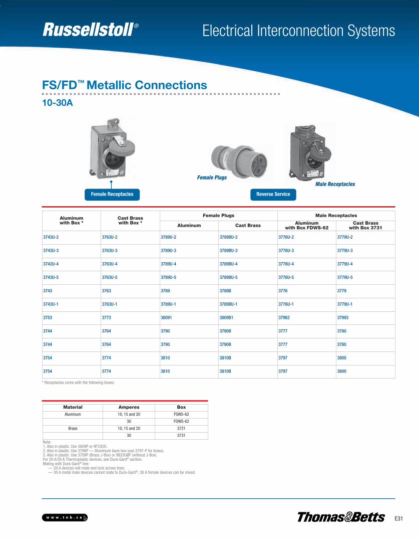
FS/FD™ Metallic Connections10-30A
Male Receptacles
Female Receptacles Reverse Service
Note:1. Also in plastic. Use 3809P or 9F33UO.2. Also in plastic. Use 3796P — Aluminum back box (use 3797-P for brass).3. Also in plastic. Use 3799P (Brass J-Box) or 9B33UØF (without J-Box).For 20 A/30 A Thermoplastic devices, see Dura-Gard® section.Mating with Dura-Gard® line:
— 20 A devices will mate and lock across lines.— 30 A metal male devices cannot mate to Dura-Gard®; 30 A female devices can be mixed.
Material Amperes Box
Aluminum 10, 15 and 20 FSWS-62
30 FDWS-62
Brass 10, 15 and 20 3721
30 3731
Aluminumwith Box *
Cast Brasswith Box *
Female Plugs Male Receptacles
Aluminum Cast Brass Aluminumwith Box FDWS-62
Cast Brasswith Box 3731
3743U-2 3763U-2 3789U-2 3789BU-2 3776U-2 3779U-2
3743U-3 3763U-3 3789U-3 3789BU-3 3776U-3 3779U-3
3743U-4 3763U-4 3789U-4 3789BU-4 3776U-4 3779U-4
3743U-5 3763U-5 3789U-5 3789BU-5 3776U-5 3779U-5
3743 3763 3789 3789B 3776 3779
3743U-1 3763U-1 3789U-1 3789BU-1 3776U-1 3779U-1
3753 3773 38091 3809B1 37962 37993
3744 3764 3790 3790B 3777 3780
3744 3764 3790 3790B 3777 3780
3754 3774 3810 3810B 3797 3800
3754 3774 3810 3810B 3797 3800
* Receptacles come with the following boxes:
Female Plugs
E-Electrical Interconnection Systems-E.pdf 31 4/2/2013 9:06:53 AM
Russellstoll ®
E32 w w w . t n b . c a
Electrical Interconnection Systems
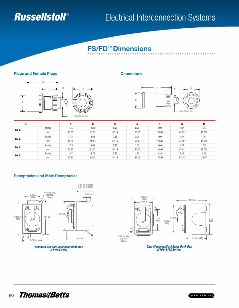
Receptacles and Male Receptacles
Plugs and Female Plugs
Max. Cable Dia.
GF H
G
Max. CableDia.
Connectors
Max. Cable Dia.
E F
G
G
B
CH H
A
A A B C E F G H
10 AInches 1.75 3.62 2.25 2.00 4.00 1.87 .75
mm 45.65 92.07 57.15 50.80 101.60 47.62 19.050
15 AInches 1.75 3.62 2.25 2.00 4.00 1.87 .75
mm 45.65 92.07 57.15 50.80 101.60 47.62 19.050
20 AInches 1.75 3.62 2.25 2.00 4.00 1.87 .75
mm 45.65 92.07 57.15 50.80 101.60 47.62 19.050
30 AInches 1.87 3.75 2.25 2.25 4.25 2.25 1.12
mm 47.62 95.25 57.15 57.15 107.95 57.15 28.57
Standard Die-Cast Aluminum Back Box(FSWS/FDWS)
Cast Aluminum/Cast Brass Back Box(3701–3732 Series)
2.75 in.
4.81 in.
3.81 in.
0.75 in.
3.81 in.
4.12 in.
2.31 in. (FS)
4.25 in.4.875 in.
MTG
2.25 in.MTG 3.37 in.
MTG2.62 in.
3 in.MTG
3 in.MTG2.94 in.
(FD)
2.94 in. (FDWS)2.31 in. (FDWS)
0.28 in. Dia.(2) MTG.
Holes
0.28 in. Dia.(2) MTGHoles
FS/FD™ Dimensions
E-Electrical Interconnection Systems-E.pdf 32 4/2/2013 9:06:53 AM
Russellstoll ®
E33w w w . t n b . c a
Electrical Interconnection Systems
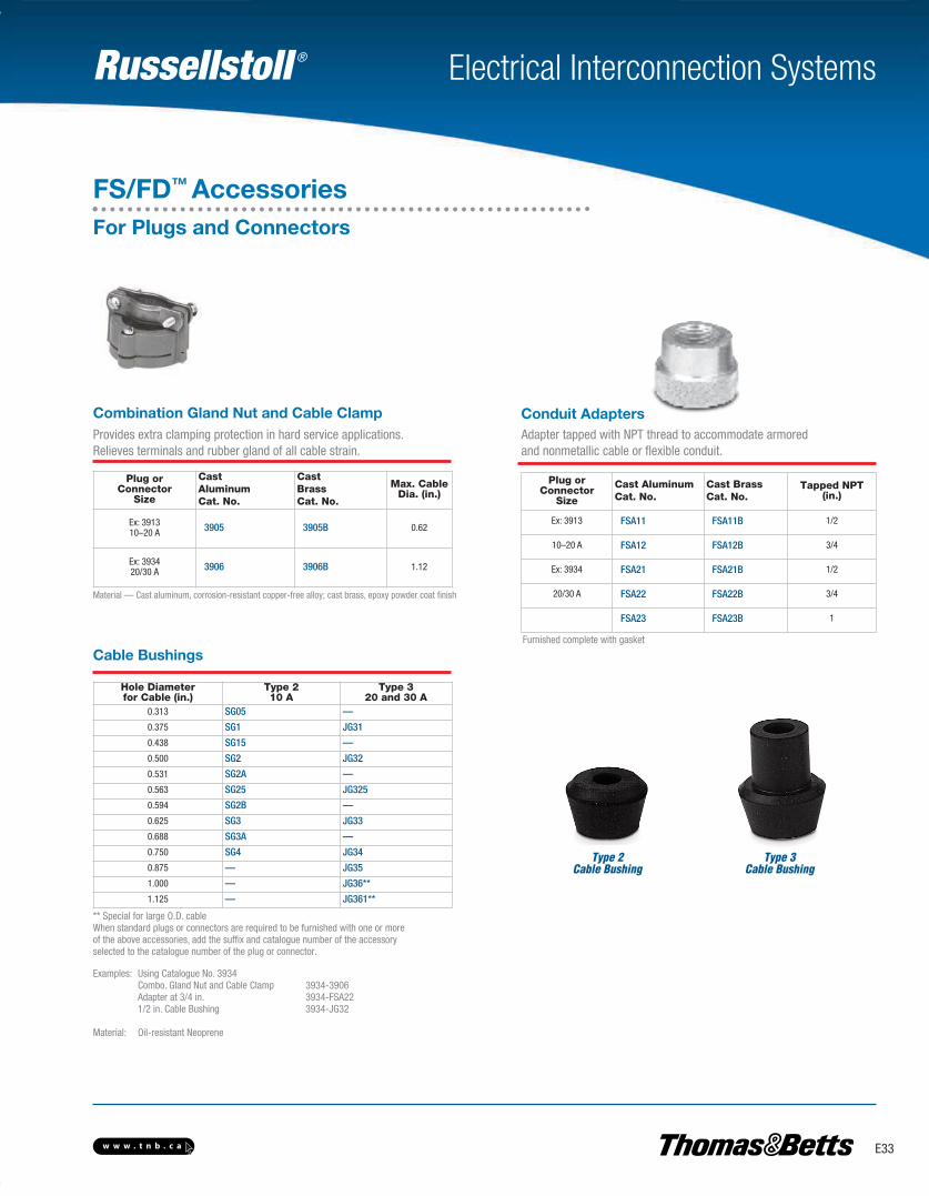
Combination Gland Nut and Cable Clamp Conduit Adapters
Cable Bushings
Type 2Cable Bushing
Type 3Cable Bushing
Plug orConnector
Size
CastAluminumCat. No.
CastBrassCat. No.
Max. CableDia. (in.)
Ex: 391310–20 A 3905 3905B 0.62
Ex: 393420/30 A 3906 3906B 1.12
Plug orConnector
Size
Cast AluminumCat. No.
Cast BrassCat. No.
Tapped NPT(in.)
Ex: 3913 FSA11 FSA11B 1/2
10–20 A FSA12 FSA12B 3/4
Ex: 3934 FSA21 FSA21B 1/2
20/30 A FSA22 FSA22B 3/4
FSA23 FSA23B 1
Hole Diameterfor Cable (in.)
Type 210 A
Type 320 and 30 A
0.313 SG05 —
0.375 SG1 JG31
0.438 SG15 —
0.500 SG2 JG32
0.531 SG2A —
0.563 SG25 JG325
0.594 SG2B —
0.625 SG3 JG33
0.688 SG3A —
0.750 SG4 JG34
0.875 — JG35
1.000 — JG36**
1.125 — JG361**
Material — Cast aluminum, corrosion-resistant copper-free alloy; cast brass, epoxy powder coat finish
** Special for large O.D. cableWhen standard plugs or connectors are required to be furnished with one or moreof the above accessories, add the suffix and catalogue number of the accessoryselected to the catalogue number of the plug or connector.
Examples: Using Catalogue No. 3934Combo. Gland Nut and Cable Clamp 3934-3906Adapter at 3/4 in. 3934-FSA221/2 in. Cable Bushing 3934-JG32
Material: Oil-resistant Neoprene
Furnished complete with gasket
Provides extra clamping protection in hard service applications. Relieves terminals and rubber gland of all cable strain.
Adapter tapped with NPT thread to accommodate armoredand nonmetallic cable or flexible conduit.
FS/FD™ AccessoriesFor Plugs and Connectors
E-Electrical Interconnection Systems-E.pdf 33 4/2/2013 9:06:53 AM
Russellstoll ®
E34 w w w . t n b . c a
Electrical Interconnection Systems
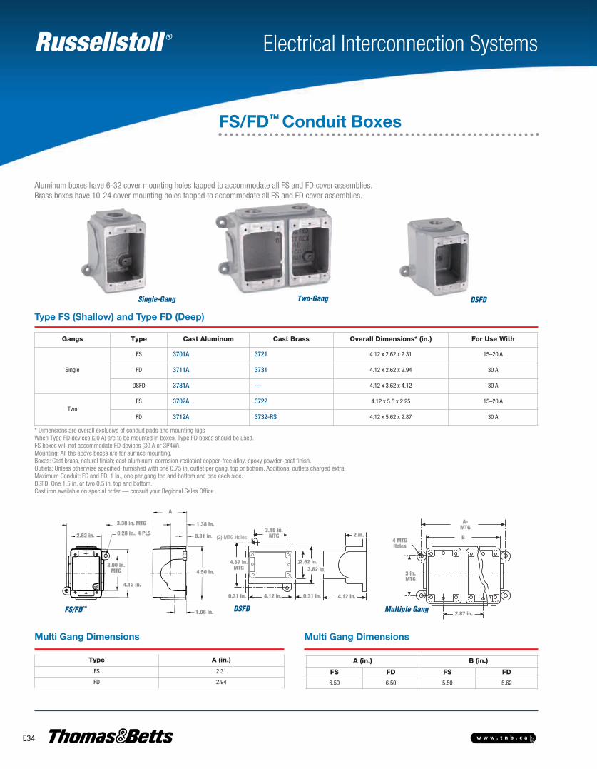
* Dimensions are overall exclusive of conduit pads and mounting lugsWhen Type FD devices (20 A) are to be mounted in boxes, Type FD boxes should be used. FS boxes will not accommodate FD devices (30 A or 3P4W).Mounting: All the above boxes are for surface mounting.Boxes: Cast brass, natural finish; cast aluminum, corrosion-resistant copper-free alloy, epoxy powder-coat finish.Outlets: Unless otherwise specified, furnished with one 0.75 in. outlet per gang, top or bottom. Additional outlets charged extra.Maximum Conduit: FS and FD: 1 in., one per gang top and bottom and one each side.DSFD: One 1.5 in. or two 0.5 in. top and bottom.Cast iron available on special order — consult your Regional Sales Office
Type FS (Shallow) and Type FD (Deep)
Aluminum boxes have 6-32 cover mounting holes tapped to accommodate all FS and FD cover assemblies.Brass boxes have 10-24 cover mounting holes tapped to accommodate all FS and FD cover assemblies.
Single-Gang Two-Gang DSFD
Gangs Type Cast Aluminum Cast Brass Overall Dimensions* (in.) For Use With
Single
FS 3701A 3721 4.12 x 2.62 x 2.31 15–20 A
FD 3711A 3731 4.12 x 2.62 x 2.94 30 A
DSFD 3781A — 4.12 x 3.62 x 4.12 30 A
TwoFS 3702A 3722 4.12 x 5.5 x 2.25 15–20 A
FD 3712A 3732-RS 4.12 x 5.62 x 2.87 30 A
Type A (in.)
FS 2.31
FD 2.94
A (in.) B (in.)
FS FD FS FD
6.50 6.50 5.50 5.62
A
1.38
.31
4.50
1.06
4.12
3.00 MTG
2.62 Ø.28, 4 PLS
3.38 MTG
4.12".31"4.12"
2"
2.62"3.62"
3.18"MTG
.31"
TG. Holes
4.37"MTG
Multiple GangFS/FD™ DSFD
2.62 in.
4.12 in.
A
1.38 in.
0.31 in.
4.50 in.
1.06 in.
0.31 in. 0.31 in.4.12 in. 4.12 in.
2.87 in.
B
A-MTG
3.62 in.2.62 in.
2 in.3.18 in.
MTG
4.37 in.MTG
3 in.MTG
(2) MTG Holes 4 MTGHoles
3.38 in. MTG
3.00 in. MTG
0.28 in., 4 PLS
FS/FD™ Conduit Boxes
Multi Gang DimensionsMulti Gang Dimensions

Russellstoll ®
E35w w w . t n b . c a
Electrical Interconnection Systems
Type FSWS and FDWS (with Mounting Shelf for Box-Mounted Devices)Aluminum die-cast boxes with cover mounting holes tapped for6-32 screws to accommodate all FS and FD cover assemblies
45° Angle Adapter*Mounts to any FS/FD™ box
Cat. No. Material
3678A Cast Aluminum
3678B Cast Brass
2.62
4.82
3.40
4.12
45°
1.88 MTG
3.25 MTG
Cat. No.Conduit Entries (in.)
Top Bottom
FSWS-62 3/4 –
FDWS-62 3/4 –
FDWS-622 3/4 3/4
FDWS-63 1 –
FDWS-633 1 1
* Furnished complete with gasket and screwsNote:Materials — Cast aluminum, corrosion-resistant copper-free alloy, epoxy powder-coat finish;cast brass, natural finish.Boxes — Aluminum die-cast, corrosion-resistant copper-free alloy, epoxy powder-coat finishOutlets — Standard as listedMounting — All of the above boxes are for surface mounting
* Furnished complete with gasket and screws
0.28 IN. Dia.(2) MTGHoles
0.28 in. Dia.(2) MTG Holes
FS/FD™ Adapters and Boxes
0.75 in.
2.25 in.MTG
4.87 in.MTG
2.25 in.
4.87 in.MTG
4.87 in.MTG
2.25 in.MTG
2.25 in.0.25 in.
5.37 in.
2.31 in.
E-Electrical Interconnection Systems-E.pdf 35 4/2/2013 9:06:53 AM
Russellstoll ®
E36 w w w . t n b . c a
Electrical Interconnection Systems
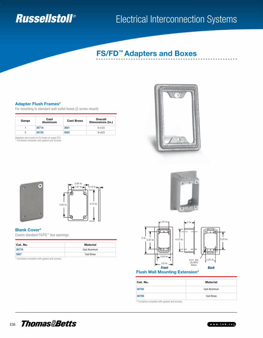
Front Back
0.21 Dia(4) MTGHoles
Adapter Flush Frames*For mounting to standard wall outlet boxes (2-screw mount)
Covers standard FS/FD™ box openings
Flush Wall Mounting Extension*
Blank Cover*
Gangs CastAluminum Cast Brass Overall
Dimensions (in.)
1 3671A 3681 5 x 3.5
2 3672A 3682 5 x 6.5
Adapters and covers to fit boxes on page E35* Furnished complete with gasket and screws
* Furnished complete with gasket and screws
* Furnished complete with gasket and screws.
2.95"1.87"
3.25" 4.15"
.15"2.95 in.1.87 in. 0.15 in.
4.15 in.3.25 in.
Cat. No. Material
3677A Cast Aluminum
3687 Cast Brass
Cat. No. Material
3679A Cast Aluminum
3679B Cast Brass
FS/FD™ Adapters and Boxes
1.87 in. 2 in.
5 in.3.25 in.
2.62 in.
3.5 in.
4.12 in.
1.87 in.
3.25 in.
E-Electrical Interconnection Systems-E.pdf 36 4/2/2013 9:06:53 AM

Russellstoll ®
E37w w w . t n b . c a
Electrical Interconnection Systems
Marine/Industrial Series — 20 and 30 A, 250 VACMechanically interlocked FS/FD™ Interface receptacle outlets, available through 30 A 250 VAC, provide added electrical safety in branch circuits. By design, the plug must be fully inserted into the interlocked receptacle before the switch or circuit breaker can be turned to the “ON" position, andthe switch or circuit breaker must be in the “OFF" position before the plug can be withdrawn. Thisdesign ensures that when properly installed and operated, the circuit is made and broken by theswitch or circuit breaker, not by the connectors.
As with all Russellstoll products, mechanically interlocked receptacles were designed with safety,durability and performance in mind.
• Mechanical linkage prevents plug insertion or withdrawal unless switch is in “OFF" position• Circuit breaker protection available on many models• Ground contacts “make first,” “break last”
Safety
• Precision-made, self-aligning and self-wiping contacts• Receptacles provided with spring-actuated, self-closing flaps• Devices available in watertight and weathertight versions• Solderless screw terminals for convenient wiring
Performance
• Constructed of copper-free cast aluminum (some types available in brass)• Sturdy die-cast and sand-cast housings
Durability
FS/FD™
Mechanically Interlocked Receptacles
E-Electrical Interconnection Systems-E.pdf 37 4/2/2013 9:06:53 AM
Russellstoll ®
E38 w w w . t n b . c a
Electrical Interconnection Systems
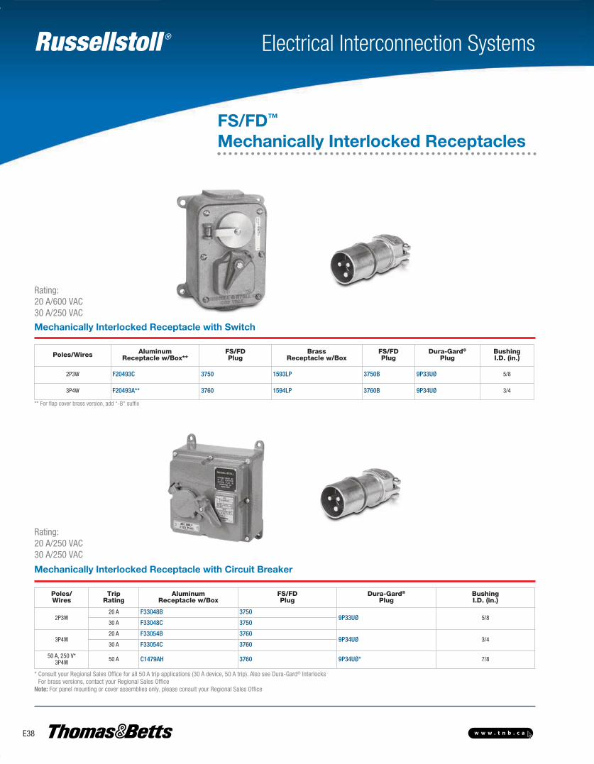
Mechanically Interlocked Receptacle with Circuit Breaker
Rating:20 A/600 VAC30 A/250 VAC
Rating:20 A/250 VAC30 A/250 VAC
Poles/Wires AluminumReceptacle w/Box**
FS/FDPlug
BrassReceptacle w/Box
FS/FDPlug
Dura-Gard®
PlugBushingI.D. (in.)
2P3W F20493C 3750 1593LP 3750B 9P33UØ 5/8
3P4W F20493A** 3760 1594LP 3760B 9P34UØ 3/4
Poles/Wires
TripRating
AluminumReceptacle w/Box
FS/FDPlug
Dura-Gard®
PlugBushingI.D. (in.)
2P3W20 A F33048B 3750
9P33UØ 5/830 A F33048C 3750
3P4W20 A F33054B 3760
9P34UØ 3/430 A F33054C 3760
50 A, 250 V*3P4W 50 A C1479AH 3760 9P34UØ* 7/8
* Consult your Regional Sales Office for all 50 A trip applications (30 A device, 50 A trip). Also see Dura-Gard® InterlocksFor brass versions, contact your Regional Sales Office
Note: For panel mounting or cover assemblies only, please consult your Regional Sales Office
** For flap cover brass version, add “-B" suffix
FS/FD™
Mechanically Interlocked Receptacles
Mechanically Interlocked Receptacle with Switch
E-Electrical Interconnection Systems-E.pdf 38 4/2/2013 9:06:53 AM
Russellstoll ®
E39w w w . t n b . c a
Electrical Interconnection Systems
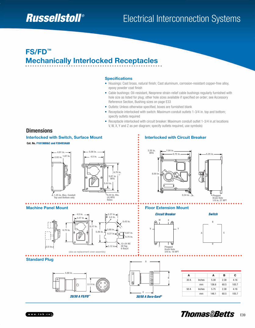
Dimensions
Specifications• Housings: Cast brass, natural finish; Cast aluminum, corrosion-resistant copper-free alloy, epoxy powder coat finish• Cable bushings: Oil-resistant, Neoprene strain-relief cable bushings regularly furnished with hole size as listed for plug; other hole sizes available if specified on order; see Accessory Reference Section, Bushing sizes on page E33• Outlets: Unless otherwise specified, boxes are furnished blank• Receptacle interlocked with switch: Maximum conduit outlets 1-3/4 in. top and bottom; specify outlets required• Receptacle interlocked with circuit breaker: Maximum conduit outlet 1-3/4 in.at locations V, W, X, Y and Z as per diagram; specify outlets required, use symbols)
Cat. No. F18196B&C and F20493A&B
20/30 A FS/FD™
Interlocked with Switch, Surface Mount Interlocked with Circuit Breaker
Machine Panel Mount Floor Extension Mount
Standard Plug
4.5"
6.75"
4.81"
2.93" 1.87"
1.25" Max. ConduitTop & Bottom only
5.06"
5.87"MTG
5.43"
.34" Dia.4 MTG.Holes
A A B C
30 A Inches 5.38 2.38 4.16
mm 136.6 60.5 105.7
50 A Inches 5.75 2.38 4.16
mm 146.1 60.5 105.7
A
B
D
C
PluggedDrain Hole3⁄8" 18 NPT
W X
Y
Z
V
SwitchCircuit Breaker
(also as replacement cover assembly)
FS/FD™
Mechanically Interlocked Receptacles
0.34 in. Dia.(4) MTGHoles
12–24 NC28 Tap6 Req’d
8.50 in.
6.75 in.
2.25 in.MTG
2.93 in.
5.43 in.
4.81 in.
4.5 in.
5.06 in.
1.87 in.
1.25 in. Max. ConduitTop and Bottom only
6.75 in.
5.87 in.MTG
4.5 in.3.37 in.
6.37 in.
5.46 in.
3.37 in.4.5 in.
0.43 in.
0.87 in.
0.75 in.
3.68 in.
0.37 in.
3.12 in.
7.50 in.6.75 in.
0.34 in.
5.25 in.
PluggedDrain Hole1/8 in. 27 NPT
2.5 in.
W X
V Y
Z PluggedDrain Hole3/8 in. 18 NPT
4.88 in.
2.13 in.
A
B
C
30/50 A Dura-Gard®
E-Electrical Interconnection Systems-E.pdf 39 4/2/2013 9:06:53 AM
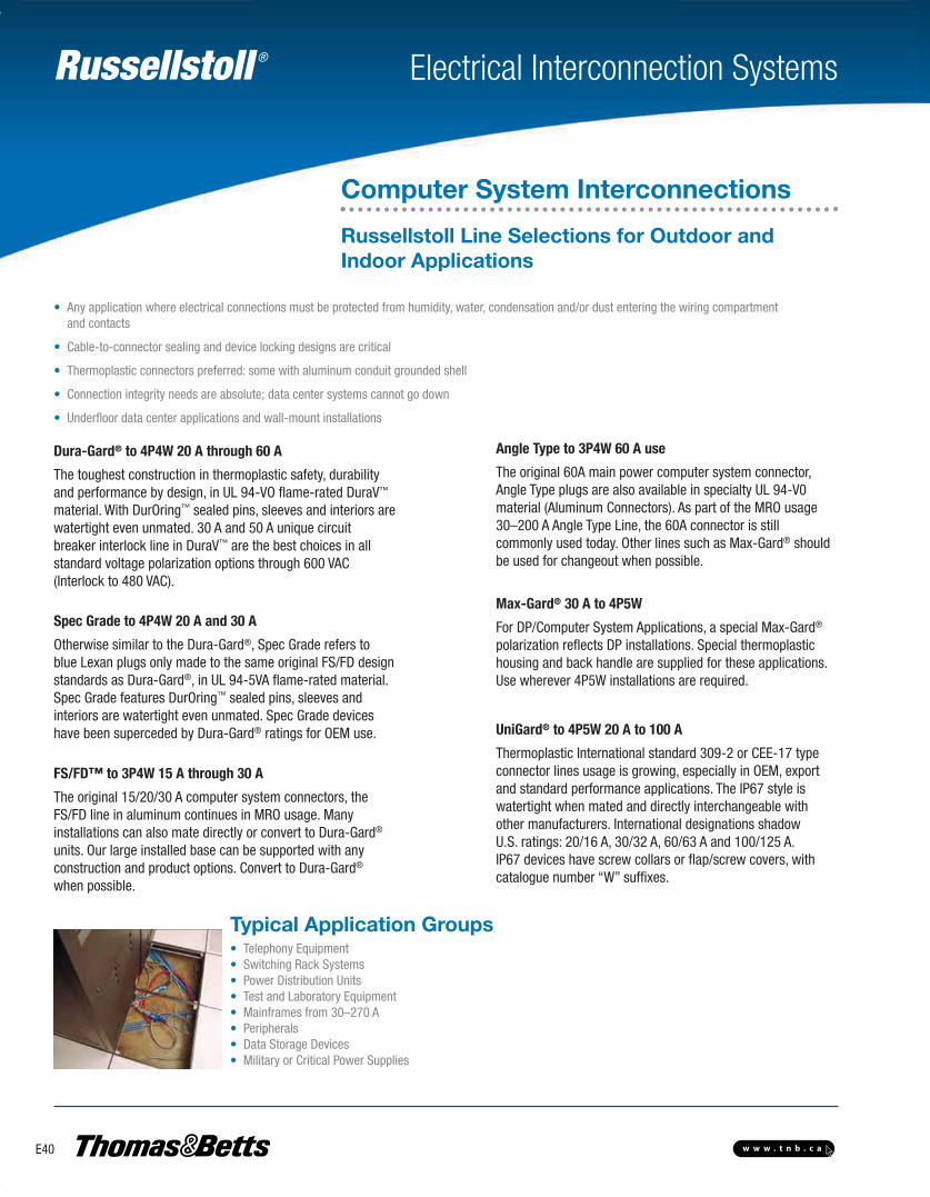
Russellstoll ®
E40 w w w . t n b . c a
Electrical Interconnection Systems
• Any application where electrical connections must be protected from humidity, water, condensation and/or dust entering the wiring compartment and contacts
• Cable-to-connector sealing and device locking designs are critical
• Thermoplastic connectors preferred: some with aluminum conduit grounded shell
• Connection integrity needs are absolute; data center systems cannot go down
• Underfloor data center applications and wall-mount installations
• Telephony Equipment• Switching Rack Systems• Power Distribution Units• Test and Laboratory Equipment• Mainframes from 30–270 A• Peripherals• Data Storage Devices• Military or Critical Power Supplies
Typical Application Groups
Computer System Interconnections
Russellstoll Line Selections for Outdoor andIndoor Applications
Dura-Gard® to 4P4W 20 A through 60 A
The toughest construction in thermoplastic safety, durabilityand performance by design, in UL 94-VO flame-rated DuraV™
material. With DurOring™ sealed pins, sleeves and interiors arewatertight even unmated. 30 A and 50 A unique circuitbreaker interlock line in DuraV™ are the best choices in allstandard voltage polarization options through 600 VAC(Interlock to 480 VAC).
Spec Grade to 4P4W 20 A and 30 A
Otherwise similar to the Dura-Gard®, Spec Grade refers toblue Lexan plugs only made to the same original FS/FD designstandards as Dura-Gard®, in UL 94-5VA flame-rated material.Spec Grade features DurOring™ sealed pins, sleeves andinteriors are watertight even unmated. Spec Grade deviceshave been superceded by Dura-Gard® ratings for OEM use.
FS/FD™ to 3P4W 15 A through 30 A
The original 15/20/30 A computer system connectors, theFS/FD line in aluminum continues in MRO usage. Manyinstallations can also mate directly or convert to Dura-Gard®
units. Our large installed base can be supported with anyconstruction and product options. Convert to Dura-Gard®
when possible.
Angle Type to 3P4W 60 A use
The original 60A main power computer system connector,Angle Type plugs are also available in specialty UL 94-V0material (Aluminum Connectors). As part of the MRO usage30–200 A Angle Type Line, the 60A connector is stillcommonly used today. Other lines such as Max-Gard® shouldbe used for changeout when possible.
Max-Gard® 30 A to 4P5W
For DP/Computer System Applications, a special Max-Gard®
polarization reflects DP installations. Special thermoplastichousing and back handle are supplied for these applications.Use wherever 4P5W installations are required.
UniGard® to 4P5W 20 A to 100 A
Thermoplastic International standard 309-2 or CEE-17 typeconnector lines usage is growing, especially in OEM, exportand standard performance applications. The IP67 style iswatertight when mated and directly interchangeable withother manufacturers. International designations shadowU.S. ratings: 20/16 A, 30/32 A, 60/63 A and 100/125 A. IP67 devices have screw collars or flap/screw covers, withcatalogue number “W” suffixes.
E-Electrical Interconnection Systems-E.pdf 40 4/2/2013 9:06:53 AM
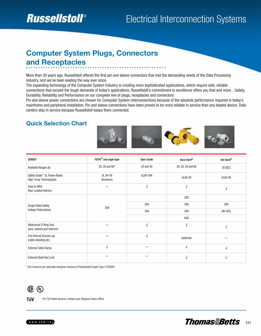
Russellstoll ®
E41w w w . t n b . c a
Electrical Interconnection Systems
SERIES* FS/FD™ and angle type Spec Grade Dura-Gard® Uni-Gard®
Available Ranges (A) 20, 30 and 60* 20 and 30 20, 30, 50 and 60 30 (IEC)
Safety Grade™ UL Flame-RatedHigh-Temp Thermoplastic
UL 94-V0 Aluminum
UL94-5VAUL94-V0 UL94-V0
Easy-to-WireRear-Loaded Interiors
— √ √√
Single Rated SafetyVoltage Polarizations
20A
20A
20A 30A 30A
30A 50A (9h–IEC)
60A
Waterproof O-Ring Seal(pins, sleeves and interiors)
— √ √√
2nd Internal Ground Lug(cable shielding alt.)
— √(optional) —
External Cable Clamp √ — √ √
External Gland Nut Lock — — √ √
For TüV listed devices, contact your Regional Sales OfficeTüV
* 60 A devices are specially designed versions of Russellstoll Angle Type (7328DP)
Computer System Plugs, Connectorsand Receptacles
More than 30 years ago, Russellstoll offered the first pin and sleeve connectors that met the demanding needs of the Data Processingindustry, and we’ve been leading the way ever since.The expanding technology of the Computer System Industry is creating more sophisticated applications, which require safe, reliableconnections that exceed the tough demands of today’s applications. Russellstoll’s commitment to excellence offers you that and more... Safety,Durability, Reliability and Performance on our complete line of plugs, receptacles and connectors.Pin and sleeve power connections are chosen for Computer System interconnections because of the absolute performance required in today’smainframe and peripheral installation. Pin and sleeve connections have been proven to be more reliable in service than any bladed device. Datacenters stay in service because Russellstoll keeps them connected.
Quick Selection Chart
E-Electrical Interconnection Systems-E.pdf 41 4/2/2013 9:06:53 AM
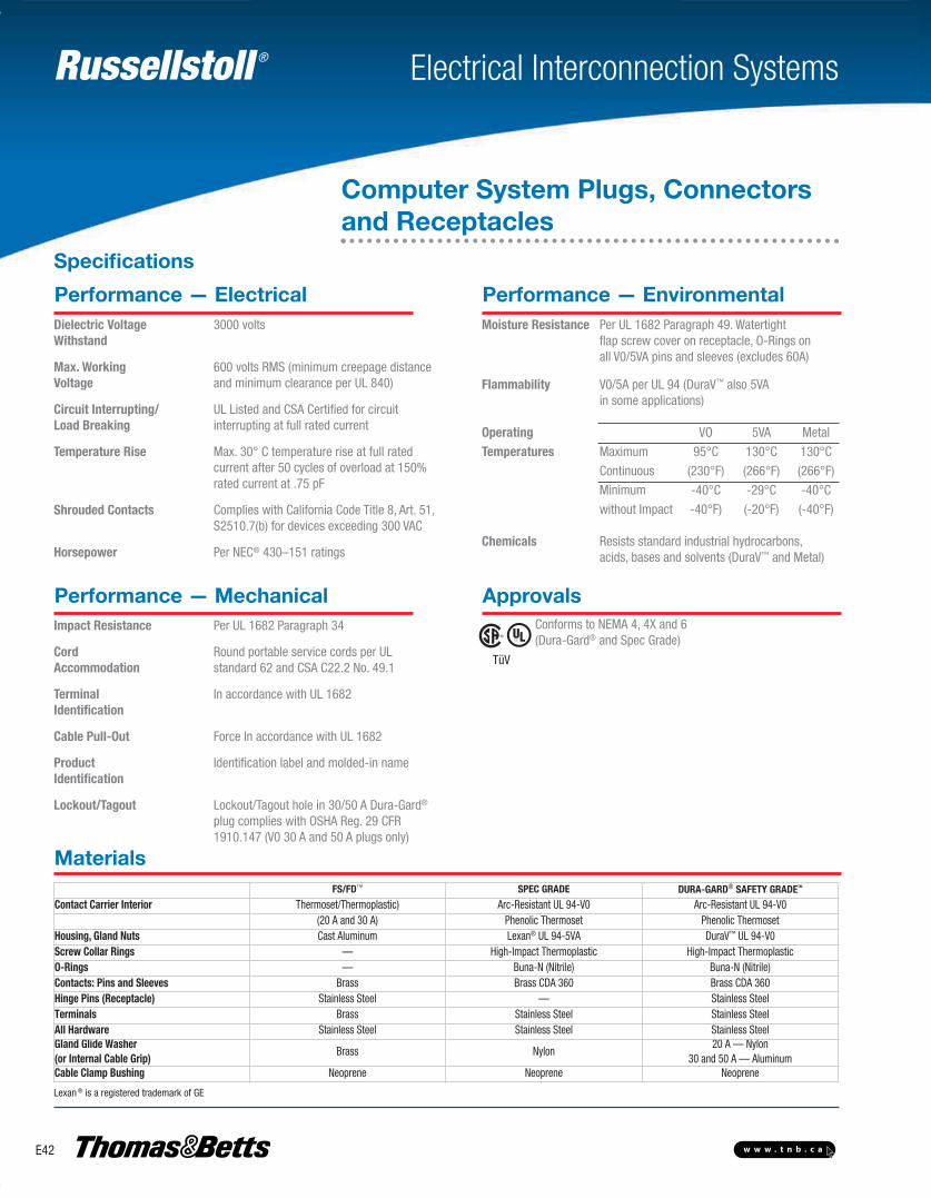
Russellstoll ®
E42 w w w . t n b . c a
Electrical Interconnection Systems
Performance — ElectricalDielectric Voltage 3000 voltsWithstand
Max. Working 600 volts RMS (minimum creepage distance Voltage and minimum clearance per UL 840)
Circuit Interrupting/ UL Listed and CSA Certified for circuitLoad Breaking interrupting at full rated current
Temperature Rise Max. 30° C temperature rise at full rated current after 50 cycles of overload at 150% rated current at .75 pF
Shrouded Contacts Complies with California Code Title 8, Art. 51, S2510.7(b) for devices exceeding 300 VAC
Horsepower Per NEC® 430–151 ratings
Performance — EnvironmentalMoisture Resistance Per UL 1682 Paragraph 49. Watertight flap screw cover on receptacle, O-Rings on all V0/5VA pins and sleeves (excludes 60A)
Flammability V0/5A per UL 94 (DuraV™ also 5VA in some applications)
Operating VO 5VA Metal
Temperatures Maximum 95°C 130°C 130°C
Continuous (230°F) (266°F) (266°F)
Minimum -40°C -29°C -40°C
without Impact -40°F) (-20°F) (-40°F)
Chemicals Resists standard industrial hydrocarbons, acids, bases and solvents (DuraV™ and Metal)
Performance — Mechanical Approvals Conforms to NEMA 4, 4X and 6 (Dura-Gard® and Spec Grade)
Impact Resistance Per UL 1682 Paragraph 34
Cord Round portable service cords per UL Accommodation standard 62 and CSA C22.2 No. 49.1
Terminal In accordance with UL 1682Identification
Cable Pull-Out Force In accordance with UL 1682
Product Identification label and molded-in nameIdentification
Lockout/Tagout Lockout/Tagout hole in 30/50 A Dura-Gard®
plug complies with OSHA Reg. 29 CFR 1910.147 (V0 30 A and 50 A plugs only)
Materials
TüV
FS/FD™ SPEC GRADE DURA-GARD® SAFETY GRADETM
Contact Carrier Interior Thermoset/Thermoplastic) Arc-Resistant UL 94-V0 Arc-Resistant UL 94-V0(20 A and 30 A) Phenolic Thermoset Phenolic Thermoset
Housing, Gland Nuts Cast Aluminum Lexan® UL 94-5VA DuraV™ UL 94-V0Screw Collar Rings — High-Impact Thermoplastic High-Impact ThermoplasticO-Rings — Buna-N (Nitrile) Buna-N (Nitrile)Contacts: Pins and Sleeves Brass Brass CDA 360 Brass CDA 360Hinge Pins (Receptacle) Stainless Steel — Stainless SteelTerminals Brass Stainless Steel Stainless SteelAll Hardware Stainless Steel Stainless Steel Stainless SteelGland Glide Washer(or Internal Cable Grip)
Brass Nylon20 A — Nylon
30 and 50 A — AluminumCable Clamp Bushing Neoprene Neoprene Neoprene
Lexan ® is a registered trademark of GE
Computer System Plugs, Connectorsand Receptacles
Specifications
E-Electrical Interconnection Systems-E.pdf 42 4/2/2013 9:06:53 AM
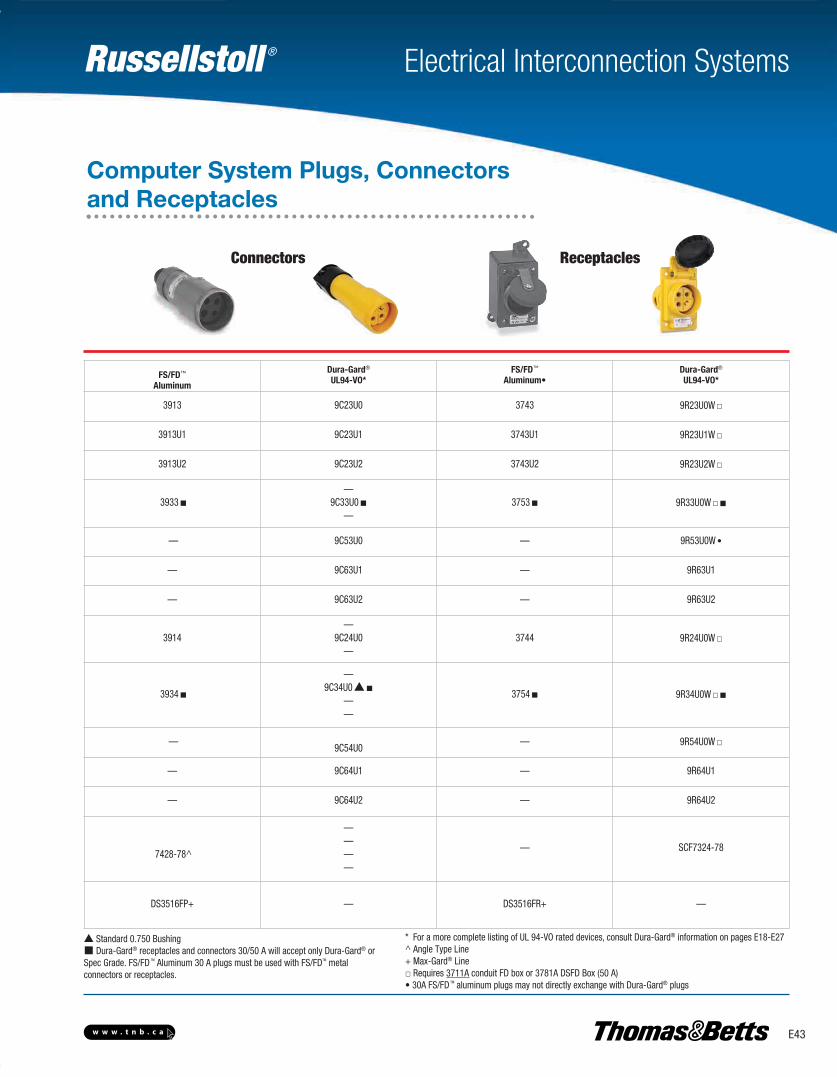
Russellstoll ®
E43w w w . t n b . c a
Electrical Interconnection Systems
FS/FD™
Aluminum
Dura-Gard®
UL94-VO*FS/FD™
Aluminum•Dura-Gard®
UL94-VO*
3913 9C23U0 3743 9R23U0W□
3913U1 9C23U1 3743U1 9R23U1W□
3913U2 9C23U2 3743U2 9R23U2W□
3933■—
9C33U0■—
3753■ 9R33U0W□■
— 9C53U0 — 9R53U0W •
— 9C63U1 — 9R63U1
— 9C63U2 — 9R63U2
3914—
9C24U0—
3744 9R24U0W□
3934■
—9C34U0▲■
——
3754■ 9R34U0W□■
—9C54U0
— 9R54U0W□
— 9C64U1 — 9R64U1
— 9C64U2 — 9R64U2
7428-78^
————
— SCF7324-78
DS3516FP+ — DS3516FR+ —
Connectors
Computer System Plugs, Connectorsand Receptacles
Receptacles
▲ Standard 0.750 Bushing■ Dura-Gard® receptacles and connectors 30/50 A will accept only Dura-Gard® or Spec Grade. FS/FD TM Aluminum 30 A plugs must be used with FS/FDTM metal connectors or receptacles.
* For a more complete listing of UL 94-VO rated devices, consult Dura-Gard® information on pages E18-E27^ Angle Type Line+ Max-Gard® Line□ Requires 3711A conduit FD box or 3781A DSFD Box (50 A)• 30A FS/FD TM aluminum plugs may not directly exchange with Dura-Gard® plugs
E-Electrical Interconnection Systems-E.pdf 43 4/2/2013 9:06:53 AM
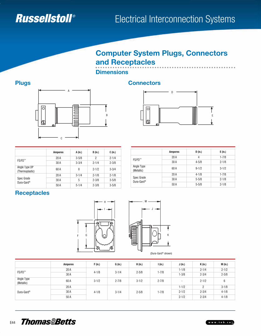
Russellstoll ®
E44 w w w . t n b . c a
Electrical Interconnection Systems
ConnectorsPlugs
Receptacles
A
B
C
D
E
A
B
D
E
C
Amperes A (in.) B (in.) C (in.)
FS/FD™20 A 3-5/8 2 2-1/4
30 A 3-3/4 2-1/4 2-3/8Angle Type DP(Thermoplastic)
60 A 8 2-1/2 3-3/4
Spec GradeDura-Gard®
20 A 3-1/4 2-1/8 2-1/8
30 A 5 2-3/8 3-5/8
50 A 5-1/4 2-3/8 3-5/8
Amperes D (in.) E (in.)
FS/FD™20 A 4 1-7/8
30 A 4-5/8 2-1/8Angle Type(Metallic)
60 A 9-1/2 3-1/2
Spec GradeDura-Gard®
20 A 4-1/8 1-7/8
30 A 5-5/8 2-1/8
50 A 5-5/8 2-1/8
Amperes F (in.) G (in.) H (in.) I (in.) J (in.) K (in.) M (in.)
FS/FD™20 A
4-1/8 3-1/4 2-5/8 1-7/81-1/8 2-1/4 2-1/2
30 A 1-3/8 2-3/4 2-5/8Angle Type(Metallic)
60 A 3-1/2 2-7/8 3-1/2 2-7/8 - 2-1/2 6
Dura-Gard®
20 A
4-1/8 3-1/4 2-5/8 1-7/8
1-1/2 2 3-1/8
30 A 2-1/2 2-3/4 4-1/8
50 A 2-1/2 2-3/4 4-1/8
(Dura-Gard® shown)
K
J
MH
GF
I
Computer System Plugs, Connectorsand ReceptaclesDimensions
E-Electrical Interconnection Systems-E.pdf 44 4/2/2013 9:06:53 AM
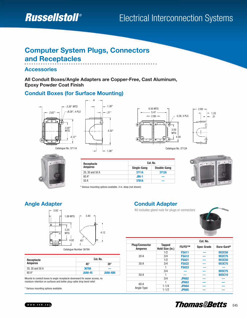
Russellstoll ®
E45w w w . t n b . c a
Electrical Interconnection Systems
Conduit Boxes (for Surface Mounting)
Angle Adapter Conduit AdapterKit includes gland nuts for plugs or connectors
A
1.38"
.31"
4.50"
1.06"
4.12"
3.00"MTG.
2.62" Ø.28", 4 PLS
3.38" MTG
Catalogue No. 3711A Catalogue No. 3712A
6.50 MTG
0.28, 4 PLS
3.00MTG
5.47
4.09
2.88
2.88
1.25.31
ReceptacleAmperes
Cat. No.
Single-Gang Double-Gang20, 30 and 50 A 3711A 3712A60 A* JB6-1 —50 A 3781A —
Catalogue Number 3678A
2.62
1.88 MTG
3.25MTG
3.40
4.12
4.82 45°
ReceptacleAmperes
Cat. No.
45° 20°20, 30 and 50 A 3678A — 60 A* JAA6-45 JAA6-AB6
* Various mounting options available. 4 in. deep (not shown)
Mounts to conduit boxes to angle receptacle downward for easier access, nomoisture retention on surfaces and better plug-cable drop bend relief.
* Various mounting options available.
Cat. No.Plug/Connector
AmperesTapped
Hold Size (in.)FS/FD™ Spec Grade Dura-Gard®
20 A1/2 FSA11 — 9X2C503/4 FSA12 — 9X2C751/2 FSA21 — 9X3C50
30 A 3/4 FSA22 — 9X3C751 FSA23 — —
3/4 — — 9X5C7550 A 1 — — 9X5C10
3/4 JPA62 — —
60 AAngle Type
1 JPA63 — —1-1/4 JPA64 — —1-1/2 JPA65 — —
Computer System Plugs, Connectorsand ReceptaclesAccessories
All Conduit Boxes/Angle Adapters are Copper-Free, Cast Aluminum,Epoxy Powder Coat Finish
E-Electrical Interconnection Systems-E.pdf 45 4/2/2013 9:06:53 AM
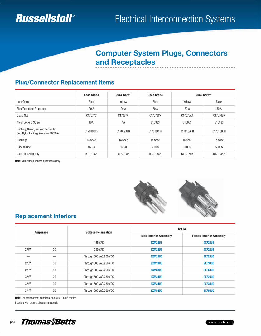
Russellstoll ®
E46 w w w . t n b . c a
Electrical Interconnection Systems
Computer System Plugs, Connectorsand Receptacles
Spec Grade Dura-Gard® Spec Grade Dura-Gard®
Item Colour Blue Yellow Blue Yellow Black
Plug/Connector Amperage 20 A 20 A 30 A 30 A 50 A
Gland Nut C17077C C17077A C17076CX C17076AX C17076BX
Nylon Locking Screw N/A NA B16983 B16983 B16983
Bushing, Clamp, Nut and Screw Kit(Inc. Nylon Locking Screw — 30/50A)
B17019CPR B17019APR B17018CPR B17018APR B17018BPR
Bushings To Spec To Spec To Spec To Spec To Spec
Glide Washer 863-8 863-8 500RS 500RS 500RS
Gland Nut Assembly B17019CR B17019AR B17018CR B17018AR B17018BR
Amperage Voltage PolarizationCat. No.
Male Interior Assembly Female Interior Assembly
— — 125 VAC 9XM23U1 9XF23U1
2P3W 20 250 VAC 9XM23U2 9XF23U2
— — Through 600 VAC/250 VDC 9XM23U0 9XF23U0
2P3W 30 Through 600 VAC/250 VDC 9XM33U0 9XF33U0
2P3W 50 Through 600 VAC/250 VDC 9XM53U0 9XF53U0
3P4W 20 Through 600 VAC/250 VDC 9XM24U0 9XF24U0
3P4W 30 Through 600 VAC/250 VDC 9XM34U0 9XF34U0
3P4W 50 Through 600 VAC/250 VDC 9XM54U0 9XF54U0
Note: Minimum purchase quantities apply
Note: For replacement bushings, see Dura-Gard® section
Interiors with ground straps are specials
Replacement Interiors
Plug/Connector Replacement Items
E-Electrical Interconnection Systems-E.pdf 46 4/2/2013 9:06:53 AM
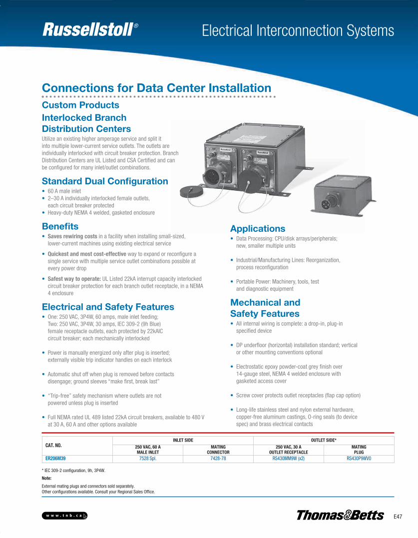
Russellstoll ®
E47w w w . t n b . c a
Electrical Interconnection Systems
Connections for Data Center Installation
CAT. NO.INLET SIDE OUTLET SIDE*
250 VAC, 60 AMALE INLET
MATINGCONNECTOR
250 VAC, 30 AOUTLET RECEPTACLE
MATINGPLUG
ER206M39 7528 Spl. 7428-78 RS430MM9W (x2) RS430P9WV0
* IEC 309-2 configuration, 9h, 3P4W.
Note:
External mating plugs and connectors sold separately.Other configurations available. Consult your Regional Sales Office.
Interlocked Branch Distribution CentersUtilize an existing higher amperage service and split itinto multiple lower-current service outlets. The outlets areindividually interlocked with circuit breaker protection. BranchDistribution Centers are UL Listed and CSA Certified and canbe configured for many inlet/outlet combinations.
Standard Dual Configuration• 60 A male inlet• 2–30 A individually interlocked female outlets, each circuit breaker protected• Heavy-duty NEMA 4 welded, gasketed enclosure
Benefits• Saves rewiring costs in a facility when installing small-sized, lower-current machines using existing electrical service
• Quickest and most cost-effective way to expand or reconfigure a single service with multiple service outlet combinations possible at every power drop
• Safest way to operate: UL Listed 22kA interrupt capacity interlocked circuit breaker protection for each branch outlet receptacle, in a NEMA 4 enclosure
Electrical and Safety Features• One: 250 VAC, 3P4W, 60 amps, male inlet feeding; Two: 250 VAC, 3P4W, 30 amps, IEC 309-2 (9h Blue) female receptacle outlets, each protected by 22kAIC circuit breaker; each mechanically interlocked
• Power is manually energized only after plug is inserted; externally visible trip indicator handles on each interlock
• Automatic shut off when plug is removed before contacts disengage; ground sleeves “make first, break last”
• “Trip-free” safety mechanism where outlets are not powered unless plug is inserted
• Full NEMA rated UL 489 listed 22kA circuit breakers, available to 480 V at 30 A, 60 A and other options available
Applications• Data Processing: CPU/disk arrays/peripherals; new, smaller multiple units
• Industrial/Manufacturing Lines: Reorganization, process reconfiguration
• Portable Power: Machinery, tools, test and diagnostic equipment
Mechanical and Safety Features• All internal wiring is complete: a drop-in, plug-in specified device
• DP underfloor (horizontal) installation standard; vertical or other mounting conventions optional
• Electrostatic epoxy powder-coat grey finish over 14-gauge steel, NEMA 4 welded enclosure with gasketed access cover
• Screw cover protects outlet receptacles (flap cap option)
• Long-life stainless steel and nylon external hardware, copper-free aluminum castings, O-ring seals (to device spec) and brass electrical contacts
Custom Products
E-Electrical Interconnection Systems-E.pdf 47 4/2/2013 9:06:53 AM
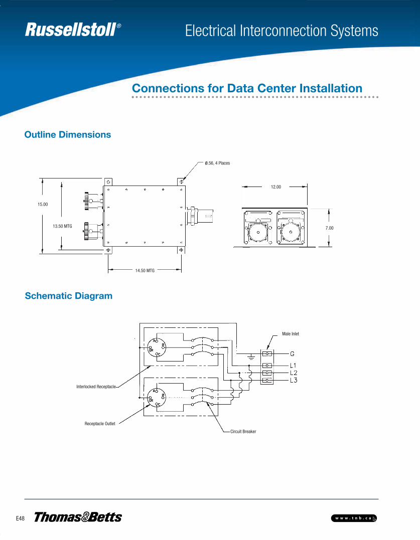
Russellstoll ®
E48 w w w . t n b . c a
Electrical Interconnection Systems
Outline Dimensions
Schematic Diagram
ø.56, 4 Places
14.50 MTG
13.50 MTG
15.00
12.00
7.00
Male Inlet
Circuit Breaker
Receptacle Outlet
Interlocked Receptacle
Connections for Data Center Installation
E-Electrical Interconnection Systems-E.pdf 48 4/2/2013 9:06:54 AM
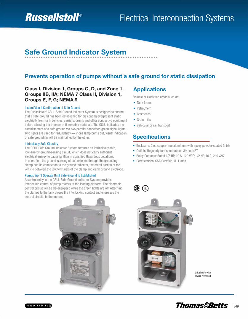
Russellstoll ®
E49w w w . t n b . c a
Electrical Interconnection Systems
Safe Ground Indicator System
Instant Visual Confirmation of Safe GroundThe Russellstoll® GSUL Safe Ground Indicator System is designed to ensurethat a safe ground has been established for dissipating everpresent static electricity from tank vehicles, carriers, drums and other conductive equipmentbefore allowing the transfer of flammable materials. The GSUL indicates theestablishment of a safe ground via two parallel connected green signal lights.Two lights are used for redundancy — if one lamp burns out, visual indicationof safe grounding will be maintained by the other.
Intrinsically Safe CircuitryThe GSUL Safe Ground Indicator System features an intrinsically safe,low-energy ground-sensing circuit, which does not carry sufficientelectrical energy to cause ignition in classified Hazardous Locations.In operation, the ground-sensing circuit extends through the groundingclamp and its connection to the ground indicator, the metal portion of thevehicle between the jaw terminals of the clamp and earth ground electrode.
Pumps Won’t Operate Until Safe Ground Is EstablishedA control relay in the GSUL Safe Ground Indicator System providesinterlocked control of pump motors at the loading platform. The electroniccontrol circuit will be de-energized while the green lights are off. Attachingthe clamps to the tank closes the interlocking contact and energizes thecontrol circuits to the motors.
Class I, Division 1, Groups C, D, and Zone 1,Groups IIB, IIA; NEMA 7 Class II, Division 1,Groups E, F, G; NEMA 9
Volatile or classified areas such as:
• Tank farms
• PetroChem
• Cosmetics
• Grain mills
• Vehicular or rail transport
Applications
Specifications• Enclosure: Cast copper-free aluminum with epoxy powder-coated finish
• Outlets: Regularly furnished tapped 3/4 in. NPT
• Relay Contacts: Rated 1/3 HP, 10 A, 120 VAC; 1⁄2 HP, 10 A, 240 VAC
• Certifications: CSA Certified, UL Listed
Unit shown withcovers removed
Prevents operation of pumps without a safe ground for static dissipation
E-Electrical Interconnection Systems-E.pdf 49 4/2/2013 9:06:54 AM
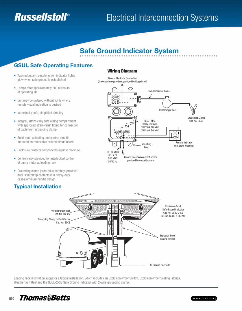
Russellstoll ®
E50 w w w . t n b . c a
Electrical Interconnection Systems
GSUL Safe Operating Features
Typical Installation
• Two redundant, parallel green indicator lights glow when safe ground is established
• Lamps offer approximately 20,000 hours of operating life
• Unit may be ordered without lights where remote visual indication is desired
• Intrinsically safe, simplified circuitry
• Integral, intrinsically safe wiring compartment with approved strain-relief fitting for connection of cable from grounding clamp
• Solid-state actuating and control circuits mounted on removable printed circuit board
• Enclosure protects components against moisture
• Control relay provided for interlocked control of pump motor at loading rack
• Grounding clamp (ordered separately) provides dual isolated tip contacts in a heavy-duty cast-aluminum handle design
Loading rack illustration suggests a typical installation, which includes an Explosion-Proof Switch, Explosion-Proof Sealing Fittings,Weathertight Reel and the GSUL-2-SS Safe Ground indicator with 2-wire grounding clamp.
TB1L1 G L2 C N.O. N.C.1 2 3 4 5 6 G
G
G2G1C
TB3
Ground Electrode Connection (1 electrode required) not provided by Russellstoll
Two-Conductor Cable
Weathertight Reel
Grounding ClampCat. No. SGC2
Remote Indicator Pilot Light(Optional)Mounting
Feet
N.O. - N.C. Relay Contacts1/3 H.P. 10 Amp 120 VAC1/2 H.P. 10 Amp 240VAC
To 115 Volts,60 Hz
Ground in explosion-proofportion provided by conduitsystem
Weathertight Reel
MountingFeet
Ground in explosion-proof portionprovided by conduit system
To 115 Volts, 60 Hz or240 VAC, 50/60 Hz
Wiring DiagramGround Electrode Connection
(1 electrode required not provided by Russellstoll)
Two-Conductor Cable
N.O. – N.C. Relay Contacts
1⁄3 HP 10 A 120 VAC1⁄2 HP 10 A 240 VAC
Remote IndicatorPilot Light (Optional)
Grounding ClampCat. No. SGC2
Weatherproof ReelCat. No. SGR25
Grounding Clampto Fuel CarrierCat. No. SGC2
Explosion-proofSealing Fittings
Explosion ProofTumbler SwitchCat. No. 4411S7
Explosion ProofSafe Ground IndicatorCat No. GSUL-2-SS
To Ground Electrode
Weatherproof ReelCat. No. SGR25
Grounding Clamp to Fuel CarrierCat. No. SGC2
Explosion-ProofSafe Ground IndicatorCat. No. GSUL-2-SS
Cat. No. GSUL-2-SS-240
Explosion-ProofSealing Fittings
To Ground Electrode
Safe Ground Indicator System
E-Electrical Interconnection Systems-E.pdf 50 4/2/2013 9:06:54 AM
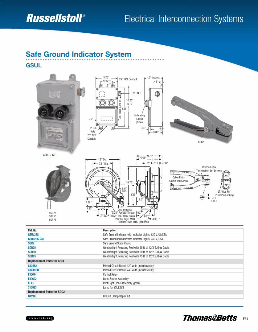
Russellstoll ®
E51w w w . t n b . c a
Electrical Interconnection Systems
Safe Ground Indicator System
5.25"3" MTG
.75" NPT Conduit
.75" NPT
10.25"MTG
9.25"
.75"
.3" Dia.Hole
.75" NPTConduit
.75"
Max
. Con
duit
4.5" Approx.
.44"
.84"
3.88"
IndicatingLights(Green)
SGR25SGR50SGR75
SGC2
13" Dia.
7.5" Dia.
9.75"3.37"
6.37"2" 3" .37"
14.75"
8.25"
2.5"
4 Sq.
0.37"
3.37"
1.25"
3" Sq.
8.5"Rad.
6.87"2 Holes Rigid MTG.
0.56" Dia. MTG. Holes0.75" Female Thread
Line Entrance1.56"
2X ConductorTermination Set Screws
Cable EntryClamp and Screw
2X “Rue Pin” Pivot Pin Locking
GSUL-2-SS
Cat. No. Description
GSUL2SS Safe Ground Indicator with Indicator Lights, 120 V, UL/CSAGSUL2SS-240 Safe Ground Indicator with Indicator Lights, 240 V, CSASGC2 Safe Ground Static ClampSGR25 Weathertight Retracing Reel with 25 ft. of 12/2 SJO-W CableSGR50 Weathertight Retracing Reel with 50 ft. of 12/2 SJO-W CableSGR75 Weathertight Retracing Reel with 75 ft. of 12/2 SJO-W Cable
Replacement Parts for GSULC13662 Printed Circuit Board, 120 Volts (includes relay)6X24RCB Printed Circuit Board, 240 Volts (includes relay)F30674 Control RelayF30602 Lamp Socket AssemblyELAG Pilot Light Globe Assembly (green)310993 Lamp for GSUL2SSReplacement Parts for SGC2 GX2TK Ground Clamp Repair Kit
GSUL
4 Holes Pivot MTG. (optional)
.146 PLS
E-Electrical Interconnection Systems-E.pdf 51 4/2/2013 9:06:54 AM
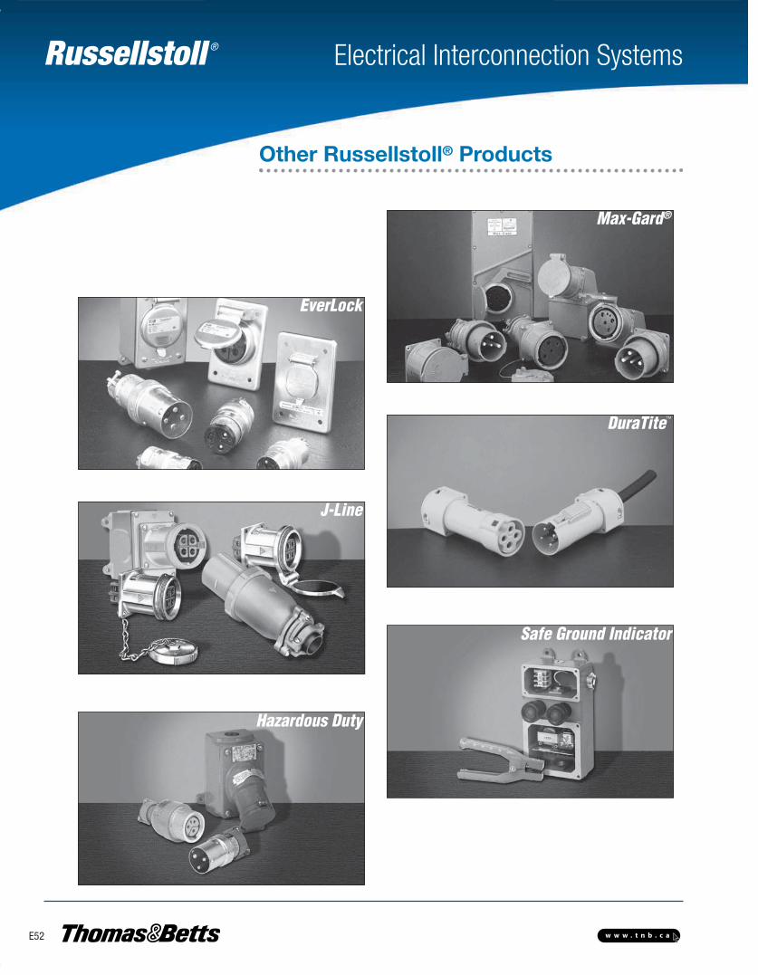
Russellstoll ®
E52 w w w . t n b . c a
Electrical Interconnection Systems
Other Russellstoll® Products
Max-Gard®
EverLock
DuraTiteTM
J-Line
Safe Ground Indicator
Hazardous Duty
E-Electrical Interconnection Systems-E.pdf 52 4/2/2013 9:06:54 AM