Rural Development Utilities Programs BULLETIN 1724E · PDF fileRural Development Utilities...
55
UNITED STATES DEPARTMENT OF AGRICULTURE Rural Development Utilities Programs BULLETIN 1724E-204 SUBJECT: Guide Specifications for Steel Single Pole and H-Frame Structures TO: All Electric Borrowers, Consulting Engineers, and RUS Electric Staff EFFECTIVE DATE: Date of Approval OFFICE OF PRIMARY INTEREST: Engineering Standards Branch; Office of Policy, Outreach, and Standards FILING INSTRUCTIONS: This bulletin replaces REA Bulletin 1724E-204, "Guide Specification for Steel Single Pole and H-Frame Structures" issued April 17, 2008. AVAILABILITY: This bulletin can be accessed via the Internet at: http://www.rd.usda.gov/publications/regulations-guidelines/bulletins/electric PURPOSE: This bulletin provides guidance that should assist borrowers in procuring steel pole and steel H-frame structures. Christopher A. McLean Date Assistant Administrator, Electric Program
Transcript of Rural Development Utilities Programs BULLETIN 1724E · PDF fileRural Development Utilities...

UNITED STATES DEPARTMENT OF AGRICULTURE Rural Development Utilities Programs
BULLETIN 1724E-204
SUBJECT: Guide Specifications for Steel Single Pole and H-Frame Structures
TO: All Electric Borrowers, Consulting Engineers, and RUS Electric Staff
EFFECTIVE DATE: Date of Approval
OFFICE OF PRIMARY INTEREST: Engineering Standards Branch; Office of Policy, Outreach, and Standards
FILING INSTRUCTIONS: This bulletin replaces REA Bulletin 1724E-204, "Guide Specification for Steel Single Pole and H-Frame Structures" issued April 17, 2008.
AVAILABILITY: This bulletin can be accessed via the Internet at:
http://www.rd.usda.gov/publications/regulations-guidelines/bulletins/electric
PURPOSE: This bulletin provides guidance that should assist borrowers in procuring steel pole and steel H-frame structures.
Christopher A. McLean Date Assistant Administrator, Electric Program

Bulletin 1724E-204 Page ii
BLANK PAGE

Bulletin 1724E-204 Page iii
ACKNOWLEDGMENTS The following current and former members of the Transmission Line Subcommittee of the National Rural Electric Cooperative Association, Transmission and Distribution Engineering Committee provided invaluable assistance in preparing this document: Ballard, Dominic, East Kentucky Power Coop., Winchester, KY Beadle, Bob, North Carolina EMC, Raleigh, NC Beckett, Thomas, Enercon, Kennesaw, GA Bertelsen, James, Dairyland Power Cooperative, La Crosse, WI Caldwell, Art, Georgia Transmission Corporation, Tucker, GA Harvey, Gary, East Kentucky Power Cooperative, Winchester, KY Johnson, Wilson, USDA, Rural Development Utilities Program, Washington, DC Kahanek, Bil, McCord Engineering, Inc., College Station, TX Lukkarila, Charles, Great River Energy, Maple Grove, MN McAndrew, Jeremy, South Mississippi Electric Power Assoc., Hattiesburg, MS Metro, Patti, National Rural Electric Cooperative Association, Arlington, VA Nordin, Bryan, Tri-State Generation & Transmission Association, Inc., Denver, CO Ruggeri, Erik, Power Engineers, Hailey, ID Shambrock, Aaron, South Central Power Company, Lancaster, OH Twitty, John, PowerSouth Energy Cooperative, Andalusia, AL Woodruff, Paul, Great River Energy, Maple Grove, MN

Bulletin 1724E-204 Page iv
TABLE OF CONTENTS INSTRUCTIONS WHEN USING GUIDE SPECIFICATIONS FOR STEEL SINGLE POLE AND H-FRAME STRUCTURES ....................................................................................... vi–xiii TECHNICAL SPECIFICATIONS ...........................................................................................1-22 1. Scope ....................................................................................................................................... 1 2. Definitions............................................................................................................................... 1 3. Codes and Standards ............................................................................................................... 2 4. Conflict Between This Specification, Drawings, And Referenced Documents ..................... 2 5. General Requirements ............................................................................................................. 2 6. Information to be Supplied by the Manufacturer .................................................................. 13 7. Approval, Acceptance, and Ownership ................................................................................ 14 8. List of Attachments to this Specifications ............................................................................ 15 Attachment A - Structure Dimensions and Other Information ...................................................16 Attachment B - Design Loads .................................................................................................... 18 Attachment C - Application Requirements ............................................................................... 20 Attachment D - Drawings .......................................................................................................... 22 Attachment E - Bid Summary-Design Information, Weights, and Costs (Information to be Submitted with Proposal) ................................................... 24 APPENDIX A - COMMENTARY APPENDIX B - EXAMPLES OF ATTACHMENTS A AND B APPENDIX C - SELECTED SI-METRIC CONVERSIONS
ABBREVIATIONS ACI American Concrete Institute ANCO American Nut Company ANSI American National Standards Institute ASCE American Society of Civil Engineers ASTM American Society for Testing and Materials AWS American Welding Society DFT Dry Film Thickness D/t Diameter of a circular section to plate thickness Eq. F Equivalency Factor ksi kips (1000 lb.) per square inch kV kilovolt mph miles per hour LF Load factor NESC National Electrical Safety Code NEMA National Electrical Manufacturers Association SSPC Steel Structure Painting Council OHGW Overhead ground wire psf pounds per square foot psi pounds per square inch UNC Unified Coarse threads
Bulletin 1724E-204 Page v
DEFINITIONS Borrower - An entity which borrows or seeks to borrow money from, or arranges financing with the assistance of the Agency through guarantees, lien accommodations or lien subordinations. Rural Development Utilities Programs Forms – All forms and bulletins referred to in this bulletin are Rural Development Utilities Programs forms and bulletins, unless otherwise noted. Form 198 - Equipment Contract Rural Development Electric Program – An Agency within Rural Development, formerly Rural Utilities Service (RUS).
INDEX: POLES: Steel MATERIALS AND EQUIPMENT: Guide Specifications for Steel Pole Structures SPECIFICATIONS AND STANDARDS: Guide Specifications for Steel Pole Structures TRANSMISSION FACILITIES: Poles (Steel)
Bulletin 1724E-204 Page vi
INSTRUCTIONS
1. PURPOSE
The intent of this guide specification is to provide Rural Development Electric Program borrowers with a basis for procuring adequate single pole and H-frame steel transmission line structures. Use of this specification should help eliminate ambiguities that might arise in the evaluation process of competitively bid steel pole procurements.
Borrowers or their engineering representatives will need to complete and add to this specification as appropriate. Modifications to this specification may be necessary to consider special applications or preferences of the owner.
2. SCOPE
This suggested purchase specification covers the technical aspects of design, materials, welding, inspection, delivery, and protective coatings of single circuit steel pole and steel H-frame structures, 115 kV to 230 kV. This specification does not include contract (front-end) documents or specifications for construction. The user of this specification should add these documents, including general conditions and any supplemental instructions to the bidders. This specification may be expanded to include double circuit structures, and structures over 230 kV.
3. INITIAL DESIGN CONSIDERATIONS
There are engineering decisions that should be made before completing the specifications. Some examples include:
• Amount of foundation rotation to consider for incorporating P-delta moments; • Location of point of fixity; • Embedment depths; • Load cases to be considered in addition to those required by the National
Electrical Safety Code (NESC); • Deflection limitations; and • Guy wire modulus of elasticity
4. INFORMATION TO BE COMPLETED BY THE OWNER OR OWNER’S
REPRESENTATIVE Users of this guide specification should detach the instructions and appendices and complete the following:
a. Documents and general information to be added to the specification: A number
of front-end documents and general information need to be added to the specification:

Bulletin 1724E-204 Page vii
• Form 198 Equipment Contract(Recommended for competitive bidding) • Supplemental Instructions to Bidders • General Conditions
When there is competitive bidding, it is recommended that Form 198 be used. This form covers Notice and Instructions to Bidders, Proposal, and Equipment Contract. For item b above, Supplemental Information, the user may want to add such items as Bid Submission, Bid Price and Schedule, Bid Acceptance Period, Bid Requirements, and Bid Data. A section on General Conditions could include such items as Definition of Terms, Interpretation of Bid Documents, Addenda to the Bid Documents, Insurance, Method of Payment (if Form 198 is not used), Quantities, and Tabulation of Unit Prices.
b. Requirements to the technical specifications to be added or completed by the
owner or owner’s representative and supplied to the bidders include:
(1) Configuration Requirements and Other Information (Attachment A of the Specification, or equivalent, to be added)
• Structure dimensions • Conductor support locations • Overhead ground wire (OHGW) support location(s) • Underbuild support location(s) • Guy attachment locations • General load information
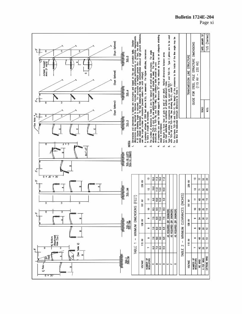
On the TUS-series single pole drawing in these instructions, minimum acceptable dimensions are recommended. Specific project designs may require greater values than the minimum to improve insulator swing or galloping performance. The distance shown on the TUS-series drawing from the top phase conductor attachment point to the static wire attachment point provides for a 30° shielding angle. For structures heights greater than 75 feet above ground, the angle should be decreased. For areas of high isokeraunic levels, high ground resistance, or high contamination, specify insulators with the number of bells detailed in the second column under each voltage level in Tables 1 and 2 of the TUS-series drawing in these instructions. Drawings TM-S1 and TM-S2 in these instructions suggest typical structure details.
Guide drawings for H-frame structures and double circuit structures have not been included in this bulletin.
Bulletin 1724E-204 Page viii
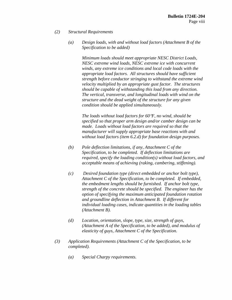
(2) Structural Requirements
(a) Design loads, with and without load factors (Attachment B of the Specification to be added)
Minimum loads should meet appropriate NESC District Loads, NESC extreme wind loads, NESC extreme ice with concurrent winds, any extreme ice conditions and local code loads with the appropriate load factors. All structures should have sufficient strength before conductor stringing to withstand the extreme wind velocity multiplied by an appropriate gust factor. The structures should be capable of withstanding this load from any direction. The vertical, transverse, and longitudinal loads with wind on the structure and the dead weight of the structure for any given condition should be applied simultaneously.
The loads without load factors for 60°F, no wind, should be specified so that proper arm design and/or camber design can be made. Loads without load factors are required so that the manufacturer will supply appropriate base reactions with and without load factors (item 6.2.d) for foundation design purposes.
(b) Pole deflection limitations, if any, Attachment C of the Specification, to be completed. If deflection limitations are required, specify the loading condition(s) without load factors, and acceptable means of achieving (raking, cambering, stiffening).
(c) Desired foundation type (direct embedded or anchor bolt type),
Attachment C of the Specification, to be completed. If embedded, the embedment lengths should be furnished. If anchor bolt type, strength of the concrete should be specified. The engineer has the option of specifying the maximum anticipated foundation rotation and groundline deflection in Attachment B. If different for individual loading cases, indicate quantities in the loading tables (Attachment B).
(d) Location, orientation, slope, type, size, strength of guys,
(Attachment A of the Specification, to be added), and modulus of elasticity of guys, Attachment C of the Specification.
(3) Application Requirements (Attachment C of the Specification, to be
completed). (a) Special Charpy requirements.

Bulletin 1724E-204 Page ix
(b) Diameter and taper limitations, if any (flat-to-flat diameter for
other than a round cross section). (c) Desired method of surface protection. If a special corrosion
problem exists, this should be mentioned, along with the recommended solution.
(d) Preference of climbing ladders, working ladders or step bolts.
Also, quantity of removable ladders or step bolts to be supplied with the total order of poles should be specified.
(e) Component weight and/or length restrictions, if any. (f) Delivery schedule and free on board (FOB) destination, and
owners’contact.
(g) Miscellaneous. (Additional items such as special attachment requirements, grounding requirements, climbing devices, hot line maintenance requirements.)
(h) Structures to be tested, if any, and number of load cases for each structure test.
(4) Structure drawing details (Attachment D of the Specification, to be added
by owner).
Drawings TUS series, TM-S1, and TM-S2 on pages xi, xii, and xiii of these instructions are provided as guidance drawings for development of Attachment D of the Specification.
5. INFORMATION TO BE COMPLETED BY THE MANUFACTURER
a. The owner or owner's representative should have the following information
completed by the bidders and submitted with the manufacturer’s proposal. Attachment E of the Specification is a sample bid summary which includes this information.
(1) Calculated shipping weight of each structure, subassemblies, and
components, excluding anchor bolts. (2) Calculated shipping weight of anchor bolts. (3) Maximum groundline reactions (moments, shears, and axial loads,
including load factors) in poles and guy wires. (4) Anchor bolt sizes, projections, lengths, layout and locations. (5) Type of material and finish of major components, American Society of
Testing and Materials (ASTM) number and grade.

Bulletin 1724E-204 Page x
(6) Description of pole shaft, including thickness, length, diameter, cross-
sectional geometry, and method of fastening each shaft component. (7) Method of attaching arms, braces, hardware, and miscellaneous
appurtenances to structure. (8) Design exceptions.
b. Documentation which the successful bidder needs to supply for approval by owner or owner's representative prior to manufacture include:
(1) Final design calculations for pole shaft, base plate, anchor bolts, arms,
and other appurtenances, including their connections for all structures. (2) The following specific items need to be supplied:
(a) For each loading case, the total shears and axial forces, moments,
stresses, deflections, section moduli, cross-sectional area, safety factors (allowable stress/actual combined stresses); the w/t's for polygonal and D/t's for round cross sections at all attachment points, at top and bottom, and at least every ten (10) feet along the pole shall be supplied.
(b) Guy reactions for each loading case. (c) For the critical loading case, shears and axial forces, moments,
stresses, section modulus, cross-sectional area, and safety factor at the arm connections. Deflections at the end of the arm should also be given.
(d) Anticipated deflection at the top of the pole and at the end of the
arms for each pole for the no wind load case at 60°F without load factors.
(e) For all specified loading cases, all reactions and groundline
moments with and without the load factors. (f) Complete design/erection reproducible drawings for each
structure type. (g) Identification and weight of each structure - include the weight of
components and a bill of materials for each structure. (h) Assembly instructions.
c. Final documentation (as built) after construction. d. Test reports (as requested).
Bulletin 1724E-204 Page xi

Bulletin 1724E-204 Page xii
TM-S1

Bulletin 1724E-204 Page xiii

Bulletin 1724E-204 Page xiv
BLANK PAGE

Bulletin 1724E-204 Page 1
SPECIFICATIONS FOR
STEEL SINGLE POLE AND H-FRAME STRUCTURES
1. SCOPE This specification covers the design, materials, welding, inspection, protective coatings, drawings and delivery of steel transmission single pole and H-frame structures. The proposal submitted by the manufacturer shall include field bolts, locknuts, vangs, attachment provisions for arms and/or insulators, anchor bolts, base plates, and other necessary items to make a complete structure.
2. DEFINITIONS:
Cambering - the fabricating of a slight convex curve in a pole or crossarm D/t - the ratio of the diameter of a tubular pole to the steel plate thickness Engineer - a registered or licensed person, who may be a staff employee or an outside consultant, and who provides engineering services. Engineer also includes duly authorized assistants and representatives of the licensed person. Groundline - a designated location on the pole where the surface of the ground will be after installation of a direct embedded pole Load factors (LF) - a multiplier which is applied to each of the vertical, transverse and longitudinal structure loads to obtain an ultimate load P-delta (P-∆) moment - secondary moment created by the vertical loads acting on the structure when the structure deflects from its unloaded position Point of fixity - location on the pole at groundline or below groundline where the maximum moment occurs. Pole twist - spiral rotation of a pole section relative to the pole end. It is caused by the residual stress in the steel as received from the mill, the clamping force holding the tube shells together and the heat applied during the seam welding process. Raking - the practice of installing a straight pole out of plumb, or at an inclined angle w/t - Ratio of the width of the pole (flat-to-flat) to the plate thickness Ultimate load - The maximum design load which includes the appropriate load factor specified UNC – Unified Coarse Threads
Bulletin 1724E-204 Page 2
3. CODES AND STANDARDS
Codes, standards, or other documents referred to in this specification shall be considered as part of this specification. The following codes and standards are referenced:
a. American Society of Civil Engineers (ASCE) Standard, Design of Steel Transmission
Pole Structures, Manual 72, latest edition. b. American Society for Testing and Materials (ASTM), various standards, latest
revision. c. American Concrete Institute (ACI), Building Code Requirements for Reinforced
Concrete, ACI 318, latest edition. d. American Welding Society (AWS), Structural Welding Code, AWS D1.1, latest
edition. e. American National Standards Institute (ANSI), National Electrical Safety Code, ANSI
C2, latest edition. f. Society for Protective Coatings (SSPC, formerly Steel Structure Painting Council)/
National Association of Corrosion Engineers (NACE) Surface Preparations Specification, SSPC/NACE SP-6/NACE 3.
4. CONFLICT BETWEEN THIS SPECIFICATION, DRAWINGS, AND
REFERENCED DOCUMENTS
In the event of conflict between this specification and the above referenced documents, the requirements of this specification shall take precedence. In the case of conflict between several referenced documents, the more stringent requirement shall be followed. If a conflict exits between this specification or the referenced documents and the attached drawings, the attached drawings shall be followed. If clarification is necessary, contact the owner or owner's representative.
5. GENERAL REQUIREMENTS
The design, fabrication, allowable stresses, processes, tolerances, and inspection shall conform to the ASCE Standard, Design of Steel Transmission Pole Structures (Manual 72), latest edition, with the following additions and/or exceptions:
a. Design
(1) Pole designs shall be prepared from the attached configuration drawings
(Attachments A and B of this Specification) and design loads (Attachment B of this Specification). The structure shall be capable of withstanding all specified loading cases including secondary stresses from foundation movements when specified in Attachment B of this Specification but not considering the possible
Bulletin 1724E-204 Page 3
restraining effect of conductors or shield wires. The structure shall withstand the loads without failure, permanent distortion, or exceeding any specified deflection limitations.
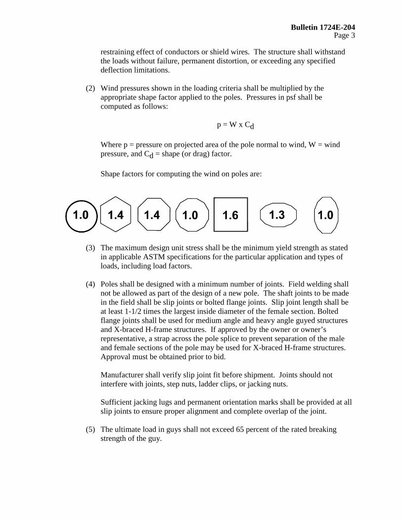
(2) Wind pressures shown in the loading criteria shall be multiplied by the
appropriate shape factor applied to the poles. Pressures in psf shall be computed as follows:
p = W x Cd
Where p = pressure on projected area of the pole normal to wind, W = wind pressure, and Cd = shape (or drag) factor.
Shape factors for computing the wind on poles are:
(3) The maximum design unit stress shall be the minimum yield strength as stated in applicable ASTM specifications for the particular application and types of loads, including load factors.
(4) Poles shall be designed with a minimum number of joints. Field welding shall
not be allowed as part of the design of a new pole. The shaft joints to be made in the field shall be slip joints or bolted flange joints. Slip joint length shall be at least 1-1/2 times the largest inside diameter of the female section. Bolted flange joints shall be used for medium angle and heavy angle guyed structures and X-braced H-frame structures. If approved by the owner or owner’s representative, a strap across the pole splice to prevent separation of the male and female sections of the pole may be used for X-braced H-frame structures. Approval must be obtained prior to bid.
Manufacturer shall verify slip joint fit before shipment. Joints should not interfere with joints, step nuts, ladder clips, or jacking nuts.
Sufficient jacking lugs and permanent orientation marks shall be provided at all slip joints to ensure proper alignment and complete overlap of the joint.
(5) The ultimate load in guys shall not exceed 65 percent of the rated breaking
strength of the guy.
Bulletin 1724E-204 Page 4
(6) Design of anchor bolts shall be in accordance with the ACI-318-1983 Edition,
Building Code Requirements for Reinforced Concrete, assuming a concrete strength as specified by the owner.
When anchor bolts are specified, they shall have the top 2 feet galvanized. Anchor bolts shall be threaded at the top end a distance equal to the baseplate thickness plus the thickness of two anchor bolt nuts plus 2-1/2”. Each anchor bolt shall include two heavy hex nuts.
Welding on anchor bolts will only be allowed in the bottom 12 inches. Only one length of anchor bolt shall be used on each pole. Anchor bolts/clusters shall be plainly marked to indicate the structure type, structure number, orientation, and top of concrete.
Anchor bolts shall be designed to be shipped as a rigid cage with top and bottom plates holding the anchor bolts in place. The anchor bolt thread shall be protected during shipping. The anchor bolts shall be welded to the holding plate in the bottom of the cage. The top template shall be designed to be removable and to support the assembled cage during lifting and setting operations without detrimental deformations. Bolt clusters shall be designed to be rigid enough to withstand the normal jolts of shipping, handling and installation with no displacement of bolts from the proper positions within the cluster.
The removable template at the top shall be marked to show the centerline for tangent structures and the angle bisector for angle structures. Matching marks are to be on the base plate of the structure so proper alignment can be made.
(7) Minimum plate thickness for all pole components shall be 3/16 inch.
(8) Structures which are to be direct embedded shall have bearing plates and ground
sleeves. Bearing plates shall have a diameter not more than 2 inches greater than the maximum pole diameter.
Galvanized poles shall have a drain hole at the bottom. The drain hole shall not be more than 20% of the bottom plate surface area. When a painted finish is specified, poles shall be hermetically sealed. Ground sleeves shall have a minimum length of 3 feet for single pole structures and 4 feet for H-frames.
The ground sleeve shall have a minimum thickness of 3/16 inch and shall be centered at the groundline. A seal weld shall be provided around the ground sleeve. The ground sleeve shall not be considered in strength calculations.
(9) Poles shall have nearly a uniform taper throughout their entire length. The
maximum difference in tapers between two pole sections measured by the diameters shall be .20 inch/ft. for poles with variable taper.
Bulletin 1724E-204 Page 5
(10) Poles with elliptical cross sections shall have a minor axis dimension equal to
at least 75 percent of the major axis dimension.
(11) All unguyed angle poles or unguyed tangent deadends shall be precambered to remain plumb when the calculated deflection at the top of the pole exceeds 1.5 percent of the pole height under an initial conductor tension loading of 60°F, no wind, and no load factors. Pole height shall be the height of the pole from the top of the baseplate, or designated groundline, to the top. Tangent poles with unbalanced vertical loadings shall be precambered for the previously stated conditions.
(12) Arms shall be designed so the end of the arm is at the specified height under a
loading of initial conductor tension, 60°F, no wind, and no load factors. Arms shall not deflect vertically more than 12 inches at the end of the arm under heavy ice conditions (without any load factors applied).
Arms shall be upswept or straight, tapered, steel tubular members, of any cross-sectional type, which meet the dimensions shown on the attached drawings (Attachment D of this Specification).
Arm end plate connection details for hardware attachment shall be typical of those shown on the attached drawings. The arms shall be hermetically sealed when a painted finish is specified. Galvanized arms shall have drain holes where appropriate. If weathering steel is used for the arms, attachments and the arm shall be designed to avoid trapping or holding moisture.
(13) Lifting lugs are optional. The manufacturer shall supply all instructions for
handling and erection of poles and arms.
(14) In the design of connections for vangs, brackets, or stiffeners attached to the pole shaft, care shall be taken to distribute the loads sufficiently to protect the wall of the pole from local buckling.
(15) Each pole shall be permanently marked on the pole shaft 60 inches above
groundline and on the bottom of baseplate or bearing plate with the following identifying information: structure type, height, structure number, ultimate groundline moment, owner name, and date manufactured. The method of identification shall be approved by the owner.
(16) Weathering steel structures shall be designed to eliminate water and refuse
traps.
Tubular sections shall be sealed from moisture entering the inside of the pole. Factory drilled pole holes shall be plugged to prevent moisture intrusion during shipping. For field drilled poles and factory drilled poles, manufacturer shall

Bulletin 1724E-204 Page 6
provide silicon sealant to seal all through-bolt holes. Nondrilled poles when assembled shall be effectively sealed to prevent moisture intrusion.
Connections shall be designed to reduce the effect of pack-out by preventing moisture from entering the joint or by designing the connection to allow moisture to easily drain off.
Plastic plugs shall be installed in all nuts welded to the structure and all tapped holes.
(17) Application requirements: (See Attachment C of this Specification)
b. Materials
(1) All materials shall comply with the applicable requirements of ASTM specifications. Any modifications to ASTM specifications must be approved by the owner's representative prior to bidding.
(2) Poles, arms and conductor brackets shall conform with ASTM A36, ASTM
A572, ASTM 581, ASTM A588, ASTM A871 or ASTM A595.
(3) Base plate shall conform with ASTM A572, ASTM A588, ASTM A633, or ASTM A595.
(4) Anchor bolts shall conform to ASTM A615, Grade 60 or 75.
(5) Other bolts and nuts shall conform, as applicable, to ASTM A307, ASTM
A325, ASTM A354, ASTM A394, or ASTM A687. Locknuts shall be provided for each structure bolt, or American Nut Company (ANCO) type self-locking nuts may be used. Locknuts shall be the galvanized MF type or ANCO type.
(6) Anchor bolts, structural plate, and weld material, shall meet ASCE
requirements for Charpy tests.
(7) For galvanized structures, steel used for the pole shaft and arms shall have a silicon content less than .06 percent.
c. Fabrication
(1) All welding shall be in accordance with the AWS D1.1, latest edition. Welders shall be qualified in accordance with AWS D1.1 welding procedures.
(2) One hundred percent penetration welds shall be required in, but not limited to,
the following areas:
Bulletin 1724E-204 Page 7
• circumferential welds (C-welds) joining structural members; • longitudinal welds in the female portion of the joint
within the slip joint area; • welds at the butt joints of back-up strips; and • base plate to shaft weld. • longitudinal welds for a minimum length of 3 inches where there
are adjacent C-welds, flange welds, base welds and ends of tubes.
(3) Full penetration or equivalent 90 percent partial penetration with fillet overlay shall be used for arm-to-arm base, vang-to-plate shaft, and arm box joints.
(4) Quality and acceptability of every inch of the full penetration welds shall be
determined by visual and ultrasonic inspection.
(5) All other penetration welds shall have 60 percent minimum penetration. Quality and acceptability of all welds other than full penetration welds shall be determined by visual inspection, supplemented by magnetic particle, ultrasonic or dye penetrant inspection.
(6) All weld back-up strips shall be continuous the full length of the welds. Care
shall be exercised in the design of welded connections to avoid areas of high stress concentration which could be subject to fatigue or brittle fractures.
(7) Field welding shall not be permitted except with owner’s approval and the
manufacturer’s direction in repairing a pole.
(8) All parts of the structure shall be neatly finished and free from kinks or twists. All holes, blocks, and clips shall be made with sharp tools and shall be clean-cut without torn or ragged edges.
(9) Before being laid out or worked in any manner, structural material shall be
straight and clean. If straightening is necessary, it shall be done by methods that will not damage the metal.
(10) Shearing and cutting shall be performed carefully and all portions of the work
shall be finished neatly. Copes and re-entrant cuts shall be filleted before cutting.
(11) All forming or bending during fabrication shall be done by methods that will
prevent embrittlement or loss of strength in the material being worked.
Bulletin 1724E-204 Page 8
(12) Holes for connection bolts shall be 1/16 inch larger than the nominal diameter
of the bolts. Holes in the flange plates for bolted splices shall be 1/8 inch larger than the bolt diameter. Holes in the base plates for anchor bolts shall be 3/8 inch larger than the nominal diameter of the anchor bolts. The details of all connections and splices shall be subject to the approval of the owner or his representatives.
(13) Holes in steel plates which are punched must be smooth and cylindrical
without excessive tear out or depressions. Any burrs that remain after punching shall be removed by grinding, reaming, etc.
(14) Holes of any diameter may be drilled in plate of any thickness. Care shall be
taken to maintain accuracy when drilling stacks of plates.
(15) Holes may be made by use of a machine guided oxygen torch. Flame cut edges shall be reasonably smooth and suitable for the stresses transmitted to them.
(16) Field drilled holes must be approved by the owner. If the manufacturer is aware
of the owner's intent to field drill holes, the manufacture must supply a galvanizing touch-up kit for galvanized poles or a silicon sealant for weathering steel poles.
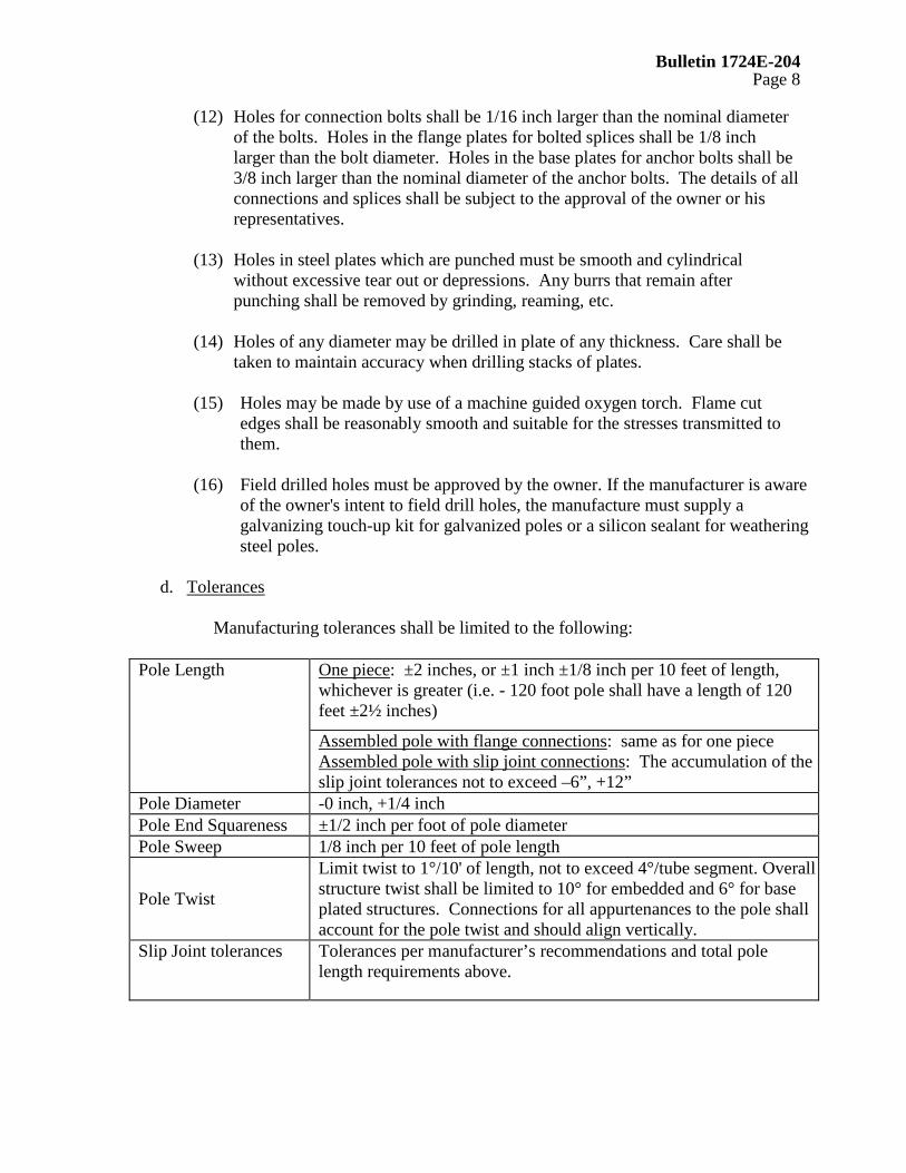
d. Tolerances
Manufacturing tolerances shall be limited to the following:
Pole Length One piece: ±2 inches, or ±1 inch ±1/8 inch per 10 feet of length, whichever is greater (i.e. - 120 foot pole shall have a length of 120 feet ±2½ inches)
Assembled pole with flange connections: same as for one piece Assembled pole with slip joint connections: The accumulation of the slip joint tolerances not to exceed –6”, +12”
Pole Diameter -0 inch, +1/4 inch Pole End Squareness ±1/2 inch per foot of pole diameter Pole Sweep 1/8 inch per 10 feet of pole length
Pole Twist
Limit twist to 1°/10' of length, not to exceed 4°/tube segment. Overall structure twist shall be limited to 10° for embedded and 6° for base plated structures. Connections for all appurtenances to the pole shall account for the pole twist and should align vertically.
Slip Joint tolerances Tolerances per manufacturer’s recommendations and total pole length requirements above.

Bulletin 1724E-204 Page 9
Location of Groups of Bolt Holes from Top of Pole
±1.0 inches (tolerance to dimension ‘A’,Figure 2)
Location of Centerline Between Groups of Bolt Holes
±1.0 inch (tolerance to dimension ‘B’, Figure 2)
Location of Holes Within a Group of Bolt Holes
±1/8 inch (tolerance to dimension ‘C’,Figure 2)
Bolt Hole Alignment Not to vary from the longitudinal pole centerline of that group of holes by more than 1/16 inch
Location of Identification Plate
±2.0 inch
e. Grounding
(1) A grounding connection shall be welded to the pole shaft, 18 inches above the
groundline or 6 inches above the ground collar. The grounding connection will be either the two-hole NEMA pad, or a nut, or a threaded insert installed in the pole, or an approved alternative.
(2) Grounding pad face shall not be painted or covered with other coatings. The
grounding nut thread and grounding pad threads shall be protected from coatings.
(3) Threaded inserts installed for grounding shall be made of Type 316 stainless steel and provided with standard ½ inch, 13 UNC threads. Threads shall be protected from coatings.
f. Climbing Devices
(1) Design Loads
(a) Step Bolts and removable steps: The step bolts, removable steps and attachment to the pole shall be designed to support a minimum of a 300 pound worker and equipment multiplied by a load factor as defined in paragraph 5.f.(2). The load shall be at the outer edge of the step or bolt.
(b) Removable Ladders: The ladder and each attachment to the pole shall be
designed to support a minimum of a 300 pound worker and equipment multiplied by a load factor as defined in paragraph 5.f.(2). The load shall be at the outer edge of the step or bolt.
FIGURE 2
A
B
C
C POLEL

Bulletin 1724E-204 Page 10
(2) Load Factor
A load factor of 2.0 shall be applied to the design loads in 5.6.1. These loads shall be supported without permanent deformation.
(3) Location
Climbing devices shall start 8 feet above groundline and extend to the pole top unless specified by the owner. The climbing device shall be spaced such that each step is 1 foot 6 inches apart and orientated to provide maximum ease of climbing. They shall be located to avoid interference with other attachments
g. Finishes
(1) The following finishes are acceptable: galvanizing, zinc primer and painting, weathering steel, and below grade coating.
(a) Galvanizing - All structures and structural components which are hot-dip
galvanized shall meet all the requirements of ASTM A123 or ASTM A153. Measures shall be taken to prevent warping and distortion according to ASTM A384 and to prevent embrittlement according ASTM A143. Poles made of ASTM A588 steel shall not be galvanized due to the high silicon content of the steel. One gallon of zinc enriched paint shall be provided with each five poles.
(b) Zinc Primer and Painting - Poles which are to be painted shall be
hermetically sealed to prevent corrosion of interior surfaces. After shot or sand blasting and cleaning in accordance with the surface preparations specification, SSPC/NACE SP-6/NACE 3, a zinc primer of 3 mils dry film thickness (DFT) and two coats of finish paint, each 3 mils DFT shall be applied to all exterior surfaces in accordance with the paint supplier's recommendations. One gallon each of primer and finish paint shall be supplied with each five poles. A guarantee against flaking or fading of the paint for a minimum of 5 years shall be provided.
(c) Weathering Steel - Steel shall conform to ASTM A588 or A871. After
fabrication, poles made of weathering steel shall be cleaned of oil, scale, etc., in accordance with the surface preparation specification SSPC/NACE SP-6/NACE 3, to ensure uniform and rapid formation of the protective oxide layer.
(d) Coatings for the Embedded Portion of the Pole - When poles are to be
directly embedded, a 16 mil (minimum dry film thickness), two component hydrocarbon extended polyurethane coating that is resistant to
Bulletin 1724E-204 Page 11
ultraviolet light shall be applied on the exposed surface of the embedded portion of the pole. The coating shall extend from the butt to the top of the ground sleeve. Other coatings shall be approved by the owner prior to their use.
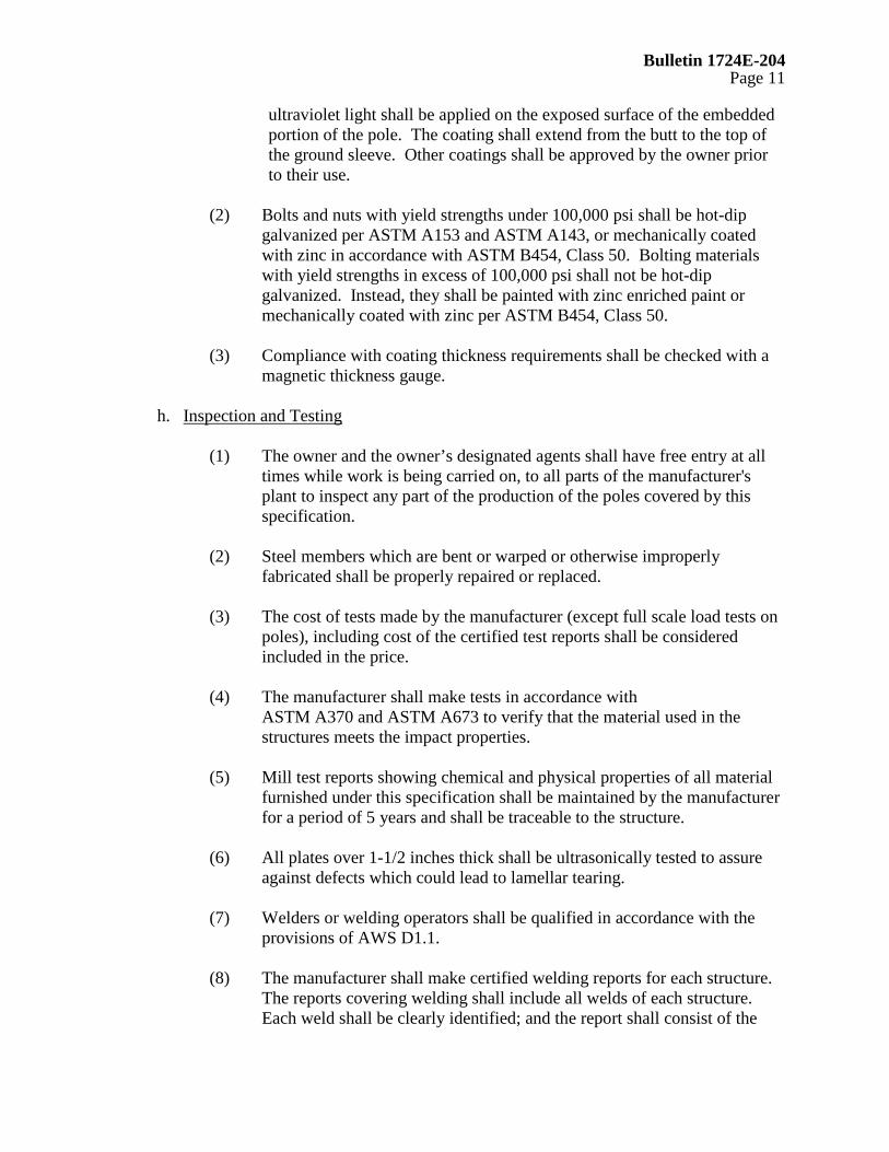
(2) Bolts and nuts with yield strengths under 100,000 psi shall be hot-dip
galvanized per ASTM A153 and ASTM A143, or mechanically coated with zinc in accordance with ASTM B454, Class 50. Bolting materials with yield strengths in excess of 100,000 psi shall not be hot-dip galvanized. Instead, they shall be painted with zinc enriched paint or mechanically coated with zinc per ASTM B454, Class 50.
(3) Compliance with coating thickness requirements shall be checked with a
magnetic thickness gauge.
h. Inspection and Testing
(1) The owner and the owner’s designated agents shall have free entry at all times while work is being carried on, to all parts of the manufacturer's plant to inspect any part of the production of the poles covered by this specification.
(2) Steel members which are bent or warped or otherwise improperly
fabricated shall be properly repaired or replaced. (3) The cost of tests made by the manufacturer (except full scale load tests on
poles), including cost of the certified test reports shall be considered included in the price.
(4) The manufacturer shall make tests in accordance with
ASTM A370 and ASTM A673 to verify that the material used in the structures meets the impact properties.
(5) Mill test reports showing chemical and physical properties of all material
furnished under this specification shall be maintained by the manufacturer for a period of 5 years and shall be traceable to the structure.
(6) All plates over 1-1/2 inches thick shall be ultrasonically tested to assure
against defects which could lead to lamellar tearing. (7) Welders or welding operators shall be qualified in accordance with the
provisions of AWS D1.1. (8) The manufacturer shall make certified welding reports for each structure.
The reports covering welding shall include all welds of each structure. Each weld shall be clearly identified; and the report shall consist of the
Bulletin 1724E-204 Page 12
method of testing, whether the weld is acceptable, the identification of the structure, the date, and the name and signature of the inspector.
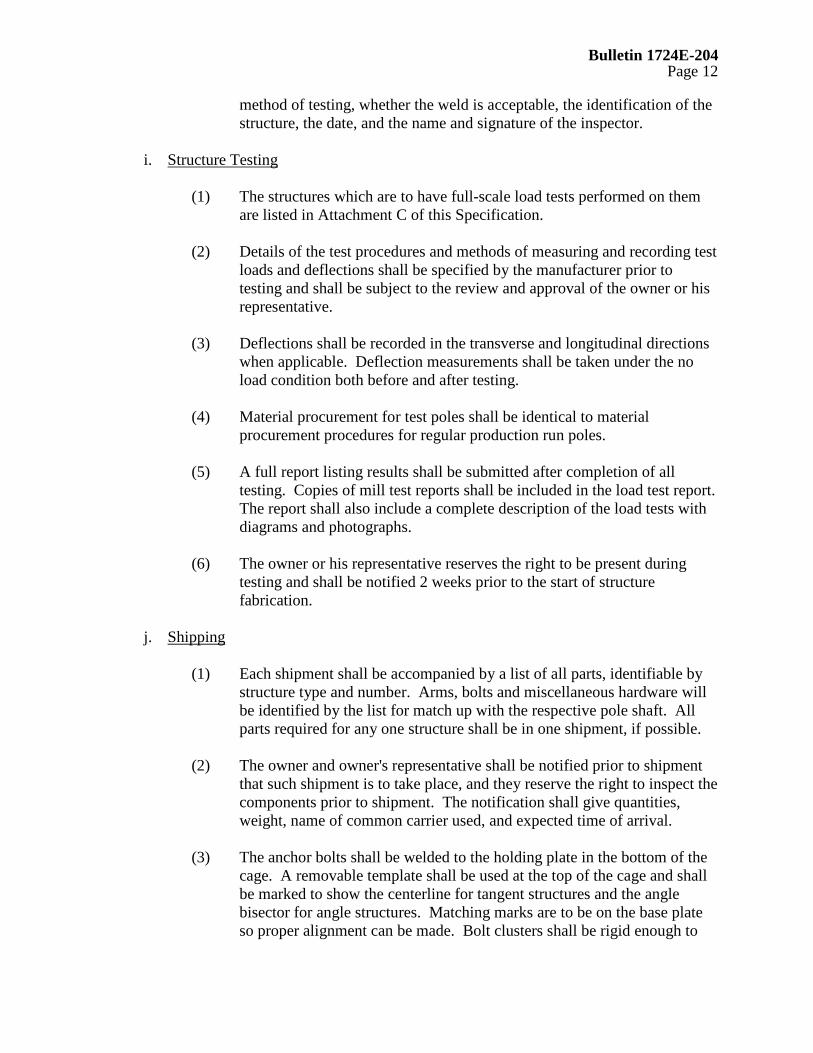
i. Structure Testing
(1) The structures which are to have full-scale load tests performed on them are listed in Attachment C of this Specification.
(2) Details of the test procedures and methods of measuring and recording test
loads and deflections shall be specified by the manufacturer prior to testing and shall be subject to the review and approval of the owner or his representative.
(3) Deflections shall be recorded in the transverse and longitudinal directions
when applicable. Deflection measurements shall be taken under the no load condition both before and after testing.
(4) Material procurement for test poles shall be identical to material
procurement procedures for regular production run poles. (5) A full report listing results shall be submitted after completion of all
testing. Copies of mill test reports shall be included in the load test report. The report shall also include a complete description of the load tests with diagrams and photographs.
(6) The owner or his representative reserves the right to be present during
testing and shall be notified 2 weeks prior to the start of structure fabrication.
j. Shipping
(1) Each shipment shall be accompanied by a list of all parts, identifiable by structure type and number. Arms, bolts and miscellaneous hardware will be identified by the list for match up with the respective pole shaft. All parts required for any one structure shall be in one shipment, if possible.
(2) The owner and owner's representative shall be notified prior to shipment
that such shipment is to take place, and they reserve the right to inspect the components prior to shipment. The notification shall give quantities, weight, name of common carrier used, and expected time of arrival.
(3) The anchor bolts shall be welded to the holding plate in the bottom of the
cage. A removable template shall be used at the top of the cage and shall be marked to show the centerline for tangent structures and the angle bisector for angle structures. Matching marks are to be on the base plate so proper alignment can be made. Bolt clusters shall be rigid enough to

Bulletin 1724E-204 Page 13
withstand the normal jolts of shipping and handling with no displacement of bolts from the proper positions within the cluster.
(4) Unless otherwise agreed to by the owner, the anchor bolt cage shall be
shipped at least 30 days prior to pole shipment. (5) Salt-treated wood blocking and urethane foams shall not be used when
shipping or storing steel poles.
6. INFORMATION TO BE SUPPLIED BY THE MANUFACTURER a. Information to be supplied with the proposal (Attachment E of this Specification).
(1) Calculated shipping weight of each structure excluding anchor bolts. Separate weights shall be given for arms and poles.
(2) Calculated shipping weight of anchor bolts.
(3) Ultimate groundline reactions (including load factors) in poles and guy wires.
(4) Anchor bolt size, length and locations (bolt circle diameters).
(5) Type of material of major components (ASTM number).
(6) Description of pole shaft, including thickness, length, diameter, cross-sectional
geometry, and method of fastening each shaft component.
(7) Data showing the design of the arm, arm connections, arm attachment plates and brackets.
(8) Sketches or draft drawings of structure and structure attachments.
b. Documentation to be supplied for the owner’s approval prior to fabrication
Documentation includes final design calculations for pole shaft, base plate, anchor bolts, arms, and other appurtenances, including their connections for all structures. The following information shall be supplied:
(1) For the loading cases with load factors, the total shear, axial forces, moments,
stresses or stress ratios, section moduli, cross-sectional areas, deflections w/t's for polygonal and D/t's for round cross sections at all splices, at arm attachment points (top and bottom), and at least every 10 feet along the pole.

Bulletin 1724E-204 Page 14
(2) For the critical loading case, shear and axial forces, moments, stresses, section
moduli, cross-sectional areas at the arm connections, bolt stresses in the arm connection, and deflection at the end of the arm.
(3) Anticipated deflections at the top of the pole and at the ends of the arms shall be
indicated for each pole for the normal, everyday loading condition of 60°F, no wind, no load factors.
(4) For all specified loading cases, reactions and groundline moments shall be
supplied.
(5) Detail drawings for each structure type giving weights of structure components, dimensions, and bill of materials.
(6) Assembly instructions and erection drawings. Slip joint lengths and allowable
tolerances. Special handling instructions. c. Final Documents shall be supplied to the owner for the items in Section 6.b.(5), after
erection of all structures and prior to final payment.
d. Test Reports (as requested).
(1) Certified mill test reports for all structural material.
(2) Certified welding reports for each structure.
(3) Impact property test reports showing that the material used in the structures meets the impact properties.
(4) Test reports on coating thickness.
(5) Report of structure testing, when required, including photographs, diagrams, load trees, etc.
7. APPROVAL, ACCEPTANCE, AND OWNERSHIP
a. Final designs must be approved by the owner or owner's representative before
material ordering and fabrication. Material ordering and fabrication prior to approval will be at supplier's risk. It is understood that award of this contract does not constitute acceptance of design calculations submitted with the bid, if corrections are required in the final structure designs due to manufacturer's errors, omissions, or misinterpretations of the specifications, the quoted price shall not change. Approval of the drawings and calculations by the owner or the owner’s representative does not relieve the supplier of responsibility for the adequacy of the design, correctness of dimensions, details on the drawings, and the proper fit of parts.
b. After delivery, the poles will be inspected and shall be free of dirt, oil blisters, flux,
black spots, dross, tear-drop edges, flaking paint or zinc; and in general, shall be

Bulletin 1724E-204 Page 15
smooth, attractive, and unscarred. Poles not meeting this requirement shall be repaired or replaced by the fabricator at no additional cost to the owner.
c. All final drawings shall become the property of the owner, who shall have full rights
to reproduce drawings and use them as the owner sees fit, including submitting them to other vendors for the purpose of obtaining bids on future steel pole purchases.
8. LIST OF ATTACHMENTS TO THIS SPECIFICATION
• Attachment A, Structure Dimensions and Other Information (to be completed by the engineer)
• Attachment B, Design Loads (to be completed by the engineer)
• Attachment C, Application Requirements (to be completed by the engineer)
• Attachment D, Drawings (to be completed by the engineer)
• Attachment E, Bid Summary-Design Information, Weights, and Costs (to be completed by the manufacturer and submitted with proposal)
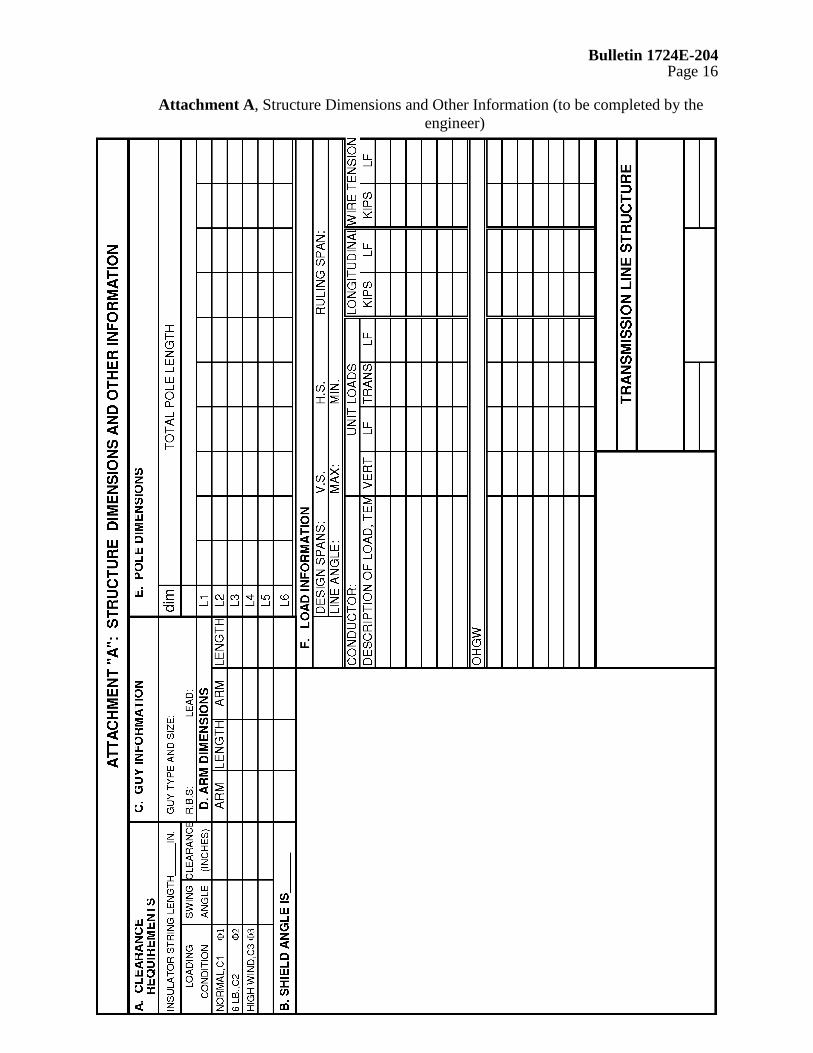
Bulletin 1724E-204 Page 16
Attachment A, Structure Dimensions and Other Information (to be completed by the
engineer)

Bulletin 1724E-204 Page 17
BLANK PAGE

Bulletin 1724E-204 Page 18
Attachment B, Design Loads (To Be Completed By The Engineer)

Bulletin 1724E-204 Page 19
BLANK PAGE
Bulletin 1724E-204 Page 20
Attachment C
Application Requirements
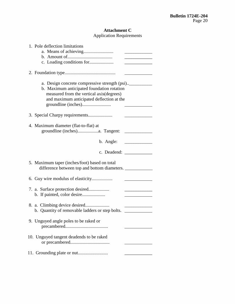
1. Pole deflection limitations a. Means of achieving.......................... ____________ b. Amount of....................................... ____________ c. Loading conditions for..................... ____________ 2. Foundation type............................................ ____________ a. Design concrete compressive strength (psi)..__________ b. Maximum anticipated foundation rotation measured from the vertical axis(degrees) and maximum anticipated deflection at the groundline (inches)......................... ____________ 3. Special Charpy requirements..................... ____________ 4. Maximum diameter (flat-to-flat) at groundline (inches)..................a. Tangent: ____________ b. Angle: ____________ c. Deadend: ____________ 5. Maximum taper (inches/foot) based on total difference between top and bottom diameters. ____________ 6. Guy wire modulus of elasticity.................. ____________ 7. a. Surface protection desired.................. ____________ b. If painted, color desire.................... ____________ 8. a. Climbing device desired..................... ____________ b. Quantity of removable ladders or step bolts. ____________ 9. Unguyed angle poles to be raked or precambered..................................... ____________ 10. Unguyed tangent deadends to be raked or precambered.................................. ____________ 11. Grounding plate or nut.......................... ____________

Bulletin 1724E-204 Page 21
Attachment C (Cont’d)
Application Requirements
12. Component weight restrictions................... ____________ 13. Pole length restrictions........................ ____________ 14. Delivery schedule............................... ____________ 15. Free on board destination....................... ____________ 16. Structures to be tested: Structure Type Load Cases to be Tested a. b. c.
17. Miscellaneous

Bulletin 1724E-204 Page 22
Attachment D
(Drawings to be added by owner)

Bulletin 1724E-204 Page 23
BLANK PAGE

Bulletin 1724E-204 Page 24
Attachment E, Bid Summary-Design Information, Weights, and Costs (to be completed by the
manufacturer and submitted with proposal)
Attachment E (See Hard Copy for Attachment E,
Bid Summary-Design, Weights , and Costs )

Bulletin 1724E-204 Page 25
BLANK PAGE

Bulletin 1724E-204 Appendix A
Page 1
APPENDIX A
COMMENTARY

Bulletin 1724E-204 Appendix A
Page 2
APPENDIX A
COMMENTARY ON GUIDE SPECIFICATIONS FOR STEEL POLE STRUCTURES
1. General
The necessity of a clear bid specification for the purchase of steel poles is very important to the bid evaluation process and the acquisition of structurally adequate poles. The specification should contain sufficient requirements and information so that all bids can be evaluated equally and so that the fabricator clearly understands what is expected.
The basis of the technical specification is the American Society of Civil Engineers (ASCE) standard on Design of Steel Transmission Pole Structures, with additions and/or exceptions made to the specification. There are several items in the specification which need further explanation. The section references in the commentary refer to the section in the Specifications.
2. Section 5.a - Design Requirements
Loads - Section 5.a. (1) The primary loads for transmission pole structures are weather loads and erection loads. Erection loads in the handling of the steel poles are determined by the manufacturer and included in the manufacturer’s design. Erection loads incurred in the construction of the line should be determined by the owner and specified in the loading trees. Weather loads must be clearly specified by the owner. The location and direction of loads should be indicated in a loading agenda or loading trees, and should have units of Newton’s, pounds, or kips (or for uniform wind loads on the structure, Pascal’s, lb./ft.2, or kips/ft.2). The specifying of loads in the form of general environmental criteria such as wind velocity or radial thickness of ice, is insufficient. Not only is there difficulty in evaluating bids, but there also is a greater possibility of error in calculated design loads.
ASCE Publication on the Guidelines for Electrical Transmission Line Structural Loadings, (Manual 74), describes different load conditions. Load factors for NESC light, medium, and heavy loading districts should be at least equal to those given in the latest edition of NESC for Grade B construction. Load factors for extreme ice and extreme wind should be at least 1.1. The load factors suggested for extreme conditions are made with the idea that testing of the structure will be to the calculated loads with a load factor of 1.0. Extreme wind loads for recurrence intervals greater than 50 years should also be considered. An appropriate gust factor should be applied to the wind velocity when considering wind on the structure. Arms should be able to sustain a minimum working load of 500 pounds for a lineman in addition to conductor and insulator design loads. The normal load for 60°F no wind should be given as one of the loading cases so that davit arms and/or camber of a pole can be properly designed.
Bulletin 1724E-204 Appendix A
Page 3
P-delta (P-∆) Moments The specification requires the fabricator to include in its analysis the secondary moment due to the unbalanced vertical load. Whenever there is a transverse or longitudinal load, the pole will deflect in the direction of the load. As a result, the vertical loads are no longer in its original position. The vertical loads have moved over as the pole deflects, causing additional moments (sometimes called P-∆ moments). This specification requires this deflection related moment to be included in the analysis. The deflection and resulting P-∆ moment should be calculated for the loads (including load factors) indicated in the loading agenda.
Foundation Rotation and Deflection
This specification allows the user the option of specifying a foundation rotation, either as a maximum for all load cases or as a certain amount for each load case. For purposes of bidding and design, the owner or owner’s engineer also has the option to simply specify a fixed base with no foundation rotation or deflection.
When specifying the maximum value for the foundation rotation and deflection for all load cases, the engineer establishes performance requirements for the steel pole and foundation. In determining this value, aesthetics, phase-to-structure clearances, phase-to-ground clearances, or even the ability to replumb a structure should be considered.
The specifying of a rotation and deflection for each load case is a refinement in analysis and design which allows the user to match types and probability of loads with foundation response. For instance, under a 50-year extreme wind load, one may allow more foundation deflection and rotation than under NESC heavy loading district loads.
In the case where foundation rotation-deflection is specified, the manufacturer should include such effects in calculations of final deflected pole stresses (P-∆ effects). The rotation and deflections when specified should be for the respective loads with load factors.
Longitudinal Loads Because steel poles are flexible structures, there may be a reduction in induced moments in a pole under some types of longitudinal loads due to the restraining effect of the overhead ground wires. Traditionally, static longitudinal loads are specified due to the complexity of calculating the influence of structure flexibility. Reducing these loads because of the restraining effects of the static wires presents certain difficulties in bid evaluation.
In order to be certain that steel pole bids can be evaluated on an equal basis, this specification requires that all longitudinal loads specified in the loading agenda are not to

Bulletin 1724E-204 Appendix A
Page 4
be reduced due to flexibility of the structure. If the owner wishes to take advantage of structure flexibility, then the owner's engineer should estimate structure and line parameters. The “reduced” longitudinal design loads should then be specified on the loading trees.
This approach is better than having the steel pole manufacturers account for structure flexibility since: (1) not all manufacturers have the capability to perform such an analysis, (2) the owner or owner’s engineer will have to evaluate the manufacturer's design anyway, and (3) plan and profile drawings would have to be included in the contract documents so that proper evaluation of the effect of longitudinal loads between deadends can be made.
Shape Factors - Section 5.a.(2) Shape factors (drag coefficients) have been established for various pole cross sections so that manufacturers will be designing on the same basis. These drag coefficients are a function of wind velocity, diameter, and shape of the member. If the user modifies this section of the specification in order to reflect more refined drag coefficients, the user should be certain to provide all additional information needed to clearly and precisely define the loads.
Guy Wires - Section 5.a.(5) Any time a steel pole structure is guyed, the guy type, size, modulus of elasticity and guy slope or angle must be specified by the owner. The manufacturer needs this information to properly analyze the structure. This specification limits the load in the guy to 65 percent of its ASTM rated breaking strength. The manufacturer should design the pole and guy wire(s) as a system. The manufacturer may wish to reduce pole capacity by using a larger than specified guy wire size. This action should be avoided unless the owner approves the use of a larger guy size, and subsequent anchor changes.
In design, the loads with the respective load factors are applied at appropriate locations on the guyed structure.
The guy modulus of elasticity can increase from a minimum value at the time of manufacture, to a maximum value which results from periodic stretching and relaxing during the load cycles. Ranges from 19,000 ksi to 28,000 ksi have been stated. The ASCE steel pole specification (ASCE Manual 72) has suggested a guy wire modulus of elasticity of 23,000 ksi be used by the pole designer whenever it is not specified.
Ratio of Minor to Major Axis - Section 5.a.(10)
Longitudinal loads are sometimes difficult to determine. In order to reduce the chances of a cascading failure in a tangent structure, this specification requires the minor axis of an elliptical or rectangular section to be not less than 75 percent of the major axis. This requirement will provide inherent longitudinal strength for steel pole tangent structures.
Bulletin 1724E-204 Appendix A
Page 5
In most instances, this inherent longitudinal strength is naturally provided in the design process.
Wind Induced Vibrations Members of all types of transmission structures may occasionally be subject to wind induced vibrations.
The manufacturer should detail each structure using good design practices considering this possibility. If vibrations are experienced, the owner should add additional damping to the structure. Damping may be particularly important on structures which are to be installed without conductors for an extended period of time.
Direct Embedded Steel Poles - Section 5.a.(8) There may be problems associated with requiring a base/bearing plate for direct embedded poles where soil conditions require the use of driller’s mud during the augering process. When installing the pole, the pole may float and it is impossible to set it in the foundation unless the water is removed from the hole, which may cause the sides of the hole to collapse. Specifying galvanized poles with a 6 to 12-inch diameter hole in the base plate may be necessary. Once crushed rock is placed in the bottom of the hole, the pole lowered, the drillers mud and water can be pumped out of the hole as the pole is set. The remaining water in the pole will drain out of the bottom of the pole through the crushed rock. If weathering steel poles are used and a hole is placed in the bearing plate, the embedded portion of the pole should be coated inside and outside.
Use of direct embedded steel poles should be evaluated for the first two spans outside of a substation or generating plant. The large amount of copper used in a substation grounding grid may create a galvanic corrosion cell, with the steel of the pole sacrificing itself. Anodes or extra subsurface protection may be needed.
3. Section 5.b - Materials
Charpy Requirements - Section 5.b.(6) A Charpy test is a notch-bar impact test used to compare notch sensitivities of materials. The impact values cannot be converted into energy figures for use directly in engineering design. The impact value from the notch-bar impact test is used only as a comparison test. For example, if a type of steel has been found to have a good notch toughness in service and its impact value is known, it is assumed that other types of steel having the same impact value will also have the same notch toughness. The ASCE design standard for steel poles has established impact values for the Charpy notch-bar impact test. These values are a function of yield stress, plate or bar thickness, and temperature.
Notch-bar impact tests are used to help determine if a normally ductile material might behave in a brittle manner. Three main factors which influence if a material will behave
Bulletin 1724E-204 Appendix A
Page 6
in a brittle or ductile manner are triaxiality, strain rate, and temperature. Ductile materials tend to become more brittle as triaxiality increases, strain rate increases, or temperature decreases. Since brittle materials require far less energy for fracture than ductile materials of the same strength, one can realize the importance of the Charpy test for steel poles used on transmission lines.
The tendency is to reduce temperature requirements of the Charpy test for structures to be in service in warm climates such as Louisiana or Florida. This is not recommended. However, for locations in which temperatures may be extremely low, lower temperature values may need to be specified.
The ASCE design standard specification contains Charpy requirements for structural plate, anchor bolts, and weld materials. The material used for making welds is required to meet the impact requirements for the lowest toughness requirements of the plates being joined.
4. Section 5.c - Fabrication (no comments)
5. Section 5.d - Finishes
Weathering Steel There are environments where weathering steel is not recommended in a bare, uncoated condition because the protective, tight oxide will not form properly. These environments include: (1) atmospheres containing concentrated corrosive industrial fumes, (2) marine locations subject to salt-water spray or salt-laden fogs, or (3) applications where the steel may be continuously submerged in water (salt or fresh)or buried (bare) in soil. Use of weathering steel poles near roads that are salted during the winter should be avoided.
In general, weathering steel is intended for and is most often used in a bare, uncoated condition. However, those surfaces that will not be boldly exposed to the weather or subjected to a wet-dry cycle should be protected from corrosion. Flat, horizontal surfaces are particularly vulnerable. Also, in areas where ground cover will grow to a height where it will contact the pole and rub the protective weathering steel coat off, or in areas where the vegetation will keep the pole moist, the steel surface should be protected from corrosion by application of a coating. For direct embedded steel poles, the polyurethane coating may have to be extended above the top of the ground sleeve to protect the weathering steel pole from moisture entrapped by vegetation or rubbing by groundcover.
If the pole is to be embedded in concrete, the interface between the pole, concrete, and the atmosphere should be protected in such a way as to prevent water leakage between the concrete and steel. Otherwise, moisture would remain and possibly cause corrosion at the same rate as carbon steel.
Blast cleaning after fabrication of a weathering steel pole will help to assure a cleaner, more uniform, weathering appearance in a shorter period of time.
Bulletin 1724E-204 Appendix A
Page 7
Grounding When poles are direct embedded, this specification requires a polyurethane coating to be applied to the exterior surface of the embedded portion of the pole. This coating will tend to insulate the pole from the ground and as such, supplemental grounding is necessary. When the pole is galvanized and there is no coating on the embedded portion of the pole, the pole may be used as the pole ground. If the foundation is a concrete caisson, a separate ground should be installed.
Use of copper or copperclad groundwire and rods should be avoided with direct embedded poles.
Additional Protection The owner or owner's representative should determine if the embedded poles should be protected by anodes. If it is necessary, requirements for sacrificial anodes and their installation should be incorporated in the construction specification.
6. Section 5.h - Inspection And Testing (no comments)
7. Section 5.i - Structure Testing
An option is available in the specification for full-scale testing of a structure or structures. For a manufacturer which has been designing and fabricating steel poles with the same processes for a number of years, the need for testing of a steel pole is questionable. Structure testing may be appropriate in cases where there are unusual requirements, new fabrication techniques, or where there are numerous tangent structures of the same or similar design.
8. Section 5.j - Shipping
The owner may wish to order 5 percent overage of all fastening hardware.
Lumber treated with salts (Ammoniacal copper arsenate, ACA, Ammoniacal copper zinc arsenate, ACZA, and Chromated copper arsenate, CCA) to retard “decay or fire” will chemically attack the steel. Urethane foam or some foams containing fire retardents should also not be used in packaging and shipping. When these materials become wet, they become very corrosive.
9. Section 6 - Information To Be Supplied By The Manufacturer With The Proposal
In order to properly evaluate bids, the specification requires certain information to be supplied with the bid. This information may be supplied on the preliminary drawings from the bidder. If the forms in Attachment B are used, one will be able to quickly review the information on the forms and simultaneously compare the information from the different manufacturers.
10. Section 7 - Approval, Acceptance, and Ownership (no comments)


Bulletin 1724E-204 Appendix B
Page 1
APPENDIX B
EXAMPLES OF ATTACHMENTS A & B
OF THE SPECIFICATIONS
Bulletin 1724E-204 Appendix B
Page 2
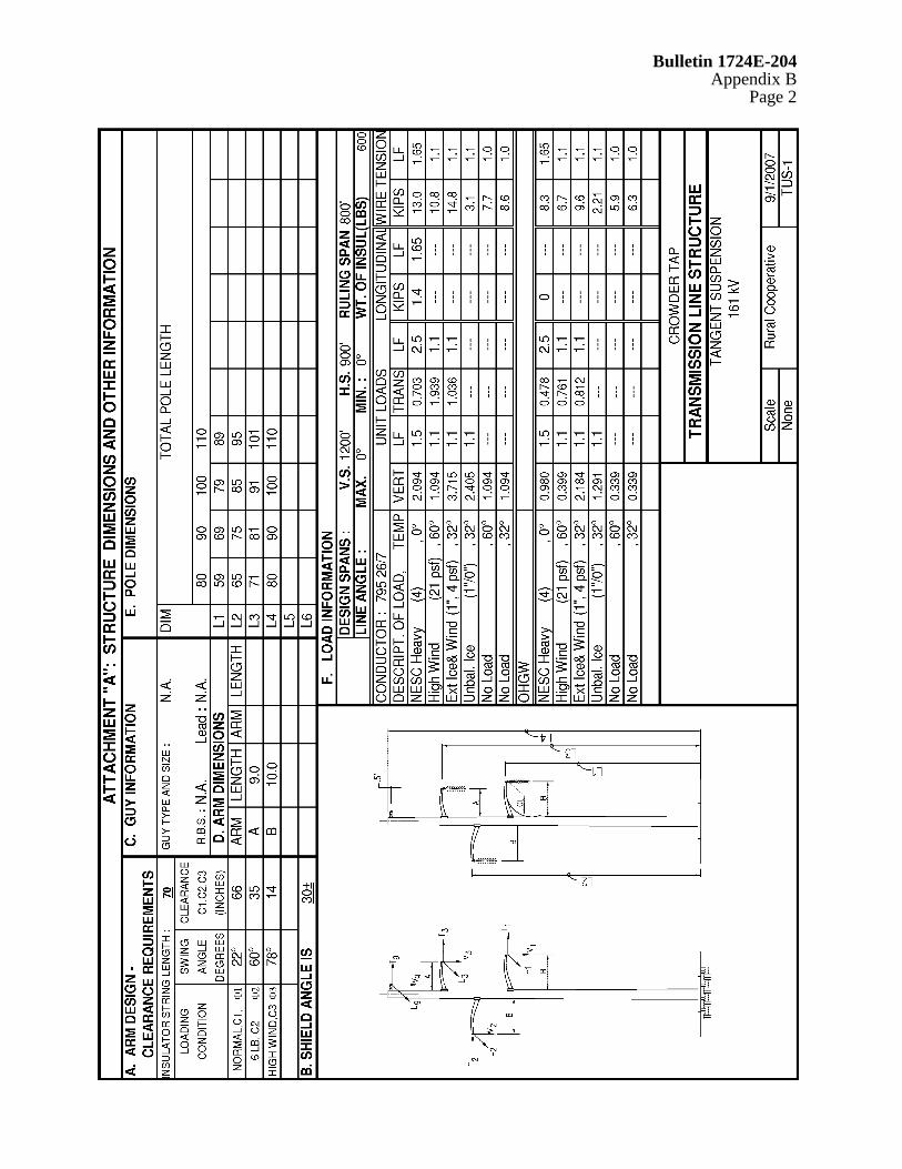
Attachment A Example (See Hard Copy of Attachment A Example)
Bulletin 1724E-204 Appendix B
Page 3
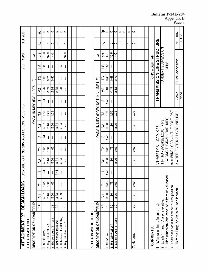
Attachment B Example (See Hard Copy of Attachment B Example)

Bulletin 1724E-204 Appendix B
Page 4
BLANK PAGE

Bulletin 1724E-204 Appendix C
Page 1
APPENDIX C
SELECTED SI-METRIC CONVERSIONS

Bulletin 1724E-204 Appendix C
Page 2
Selected SI-Metric Conversions AREA
To Convert From To Multiply By circular mil (cmil) square meter (m2) 5.067075 E-10 square centimeter (cm2) square meter (m2) *1.000 E-04 square foot (ft2) square meter (m2) *9.290304 E-02 square inch (in2) square meter (m2) *6.451600 E-04 square kilometer (km2) square meter (m2) *1.000 E+06 square mile (mi2) square meter (m2) 2.589988 E+06
FORCE To Convert From To Multiply By kilogram force (kgf) Newton (N) *9.806650 kip Newton (N) 4.448222 E+03 pound force (lbf) Newton (N) 4.44822
FORCE PER LENGTH To Convert From To Multiply By kilogram force per meter (kgf/m) Newton per meter (N/m) *9.806650 pound per foot(lb/ft) Newton per meter (N/m) 1.459390 E+01
DENSITY To Convert From To Multiply By pound per cubic inch (lb/in3) kilogram per cubic 2.767990 E+04 meter (kg/m3)
pound per cubic foot (lb/ft3) kilogram per cubic 1.601846 E+01
LENGTH To Convert From To Multiply By foot (ft) meter (m) 3.048 E-01 inch (in) meter (m) *2.540 E-02 kilometer (km) meter (m) *1.000 E+03 mile (mi) meter (m) *1.609344 E+03 *Exact Conversion

Bulletin 1724E-204 Appendix C
Page 3
Selected SI-Metric Conversions, Cont.
LOAD CONCENTRATION To Convert From To Multiply By pound per square inch (lb/in2) kilograms per square meter (kg/m2) 7.030696 E+02 pound per square foot (lb/ft2) kilograms per square meter (kg/m2) 4.788026 ton per square foot (ton/ft2) kilograms per square meter (kg/m2) 9.071847 E+02
PRESSURE To Convert From To Multiply By kip per square inch (kip/in2) Pascal (Pa) 6.894757 E+06 kip per square foot (kip/ft2) Pascal (Pa) 4.788026 E+04 Newton per square meter (N/m2) Pascal (Pa) *1.000 pound per square foot (lb/ft2) Pascal (Pa) 4.788026 E+01 pound per square inch (lb/in2) Pascal (Pa) 6.894757 E+03
BENDING MOMENT To Convert From To Multiply By kilogram force meter (kgf-m) Newton meter (N-m) *9.806650 kip-foot (kip-ft) Newton meter (N-m) 1.355818 E+02 pound-foot (lb-ft) Newton meter (N-m) 1.355818
VELOCITY To Convert From To Multiply By foot per second(ft/s) meter per second (m/s) *3.048 E-01 kilometer per hour (km/h) meter per second (m/s) 2.777778 E-01 mile per hour(mi/h) meter per second (m/s) 4.437030 E-01 meter per hour(m/h) meter per second (m/s) 2.777778 E-04 *Exact Conversion.