RUP Design RUP Artifacts and Deliverables RUP Analysis & Design Workflow.
RUP Based Analysis and Design with Aspects
Leonardo Cole1*, Eduardo Kessler Piveta
2, Augusto Sampaio
1†
1Centro de Informática, Universidade Federal de Pernambuco, Av. Prof. Luiz Freire S/N,
Recife PE, Brazil 50732-970, + 55 81 327184302Computing Security Lab (LabSEC), Federal University of Santa Catarina, University
Campus P.O.Box 476, Florianopolis SC, Brazil 88040-900, +55 48 3319498e-mail: [email protected], [email protected], [email protected]
Abstract
Aspect-Oriented Software Development (AOSD) is a new paradigm aiming to solve problems that are notadequately addressed by the Object-Oriented paradigm. Therefore, it seems appropriate to adapt softwareprocesses showing when and how crosscutting concerns should be considered. The Rational Unified Process(RUP) is one of the most widely used software development processes focusing on object-oriented softwaredevelopment, but RUP was not originally conceived considering separation of crosscutting concerns. This workproposes adjustments to one of the most affected RUP disciplines, Analysis and Design, in order to use newconcepts and techniques of AOSD. A case study is developed to validate the proposed approach.
1. Introduction
Aspect-Oriented Software Development (AOSD) is a term to denote the use of Aspect
Oriented Programming [8] during software development process. It is a new paradigm that
comes to complement the Object-Oriented (OO) paradigm, solving problems that are not
adequately solved by the later [13, 14]. These problems are related to the implementation of
some concerns that are generally spread throughout the system (code scattering). In addition,
this code is generally not related to the behaviour implemented in the context where it appears
(code tangling).
AOSD implements these crosscutting concerns in a system as first class entities (named
aspects). Each aspect defines behaviour that should be added to specific points in the
program. This structure enables the separation and modularization of crosscutting concerns.
The Rational Unified Process (RUP) [9] is one of the most widely used software development
processes. It defines disciplines, workflows, activities, roles and artifacts that control the
software development, aiming to produce software with quality, on budget and within
schedule. The RUP is designed to model an object-oriented process. It was not originally
conceived to consider a different paradigm, as AOSD. On the other hand, as a process
framework, the RUP can be specialized to specific domains and extended to incorporate new
concepts and paradigms. Hence, it is possible (and seems appropriate) to adapt the RUP,
analyzing when and how to consider the modelling of crosscutting concerns as aspects.
This work focuses on the Analysis and Design discipline. We show the adaptations to each
activity in this workflow, suggesting changes and also including new activities. Thus, our
main contribution is a set of guidelines on how to use AOSD with the RUP Analysis and
Design discipline. Despite our focus on this discipline, others, such as Requirements and
*Supported by CAPES.
†Partially supported by CNPq, grant 500895/2003-1.
210
18º Simpósio Brasileiro de Engenharia de Software18º Simpósio Brasileiro de Engenharia de Software18º Simpósio Brasileiro de Engenharia de Software18º Simpósio Brasileiro de Engenharia de Software18º Simpósio Brasileiro de Engenharia de Software18º Simpósio Brasileiro de Engenharia de Software
210210210210210
18º Simpósio Brasileiro de Engenharia de Software18º Simpósio Brasileiro de Engenharia de Software
210210
18º Simpósio Brasileiro de Engenharia de Software18º Simpósio Brasileiro de Engenharia de Software18º Simpósio Brasileiro de Engenharia de Software
210
18º Simpósio Brasileiro de Engenharia de Software18º Simpósio Brasileiro de Engenharia de Software18º Simpósio Brasileiro de Engenharia de Software
Implementation, are also considered. We discuss related work on the Requirements discipline
which is the main input to Analysis and Design.
In particular, this work can be regarded as an extension of a previous work [15], where some
new roles and activities to the Analysis and Design discipline in the presence of aspects are
suggested. Here we further develop the ideas to propose a more precise description of the
necessary adaptations to the RUP Analysis and Design (A&D) discipline. We give an
overview of each workflow detail, proposing changes to the related activities and suggesting
the creation of new ones. Moreover, we develop a case study to validate the proposed
approach.
This paper is organized as follows. Section 2 gives an overview of the RUP singling out the
Analysis and Design discipline. Next, we introduce the Requirements discipline making use
of aspects in Section 3. Then we suggest the necessary adaptations to the Analysis and Design
discipline in Section 4. In Section 5 we develop a case study based on the Analysis and
Design discipline proposed. Section 6 discusses our conclusions, related and future work,
presenting some suggestions and guidelines for the Implementation discipline.
2. The Rational Unified Process
The Rational Unified Process (RUP) [9] is a software engineering process. It can be viewed as
a framework which is extensible to be adapted for particular project needs. It provides a
disciplined approach to assigning tasks and responsibilities within a development
organization. Its goal is to ensure the production of high-quality software that meets the needs
of its end users within a predictable schedule and budget.
RUP is an object-oriented and Web-enabled software development process. It provides
guidelines, templates, and examples for all aspects and program development phases. RUP
and similar products, such as Catalysis [5] and the OPEN Process [6], are comprehensive
software engineering tools that combine defined stages, techniques, and practices with other
components of development (such as documents, models, manuals, code, and so on) within an
unifying framework.
RUP establishes four development phases, each is organized in iterations that must satisfy
defined criteria before the next phase is undertaken. The first phase is the inception, where
developers define the scope of the project and its business case. Next, in the elaboration
phase, developers analyze the project’s needs in greater detail and define its architectural
foundation. In the construction phase, developers create the application design and source
code. Finally, in the transition phase, developers deliver the system to users. Using RUP
allows the production of a functional prototype at the completion of each iteration. The way
interactions and phases take place should be configured according to specific projects
necessities and technologies.
There are four primary modelling elements: roles, activities, artifacts and workflows. Roles
represent behaviours and responsibilities of the development team participants (i.e. system
analysts, architects, designers). Activities are the work performed by the roles (i.e. find use
cases and actors, review the design and execute a performance test). Artifacts are formation
produced or used by the roles to perform activities (i.e. software architecture ocument, design
model).
Workflows (or disciplines) describe the sequence of activities that produce some value result
and show the interactions among roles. There are nine workflows considered in RUP:
Business Modelling, Requirements, Analysis and Design, Implementation, Test, Deployment,
Configuration and Change Management, Project Management, and Environment. Besides the
last three ones, most of the artifacts produced in one workflow are part of the input to the
next.
211
18º Simpósio Brasileiro de Engenharia de Software18º Simpósio Brasileiro de Engenharia de Software18º Simpósio Brasileiro de Engenharia de Software18º Simpósio Brasileiro de Engenharia de Software18º Simpósio Brasileiro de Engenharia de Software18º Simpósio Brasileiro de Engenharia de Software
211211211211211
18º Simpósio Brasileiro de Engenharia de Software18º Simpósio Brasileiro de Engenharia de Software
211211
18º Simpósio Brasileiro de Engenharia de Software18º Simpósio Brasileiro de Engenharia de Software18º Simpósio Brasileiro de Engenharia de Software
211
18º Simpósio Brasileiro de Engenharia de Software18º Simpósio Brasileiro de Engenharia de Software18º Simpósio Brasileiro de Engenharia de Software

Requirements goals are to establish and maintain agreement with the customers and other
stakeholders on what the system should do. It also provides a better understanding of the
system domain and behaviour, allowing the definition of the the system´s scope and user-
interface. In addition, it enables the estimation of costs and time to develop the system.
The purpose of Analysis and Design is to transform the requirements into a concrete design of
the system, to construct a robust architecture for the system and to adapt the design to match
the implementation environment. More details on this discipline are given in Section 4.
Implementation defines the code organization, structuring subsystems in layers. In this phase,
the design elements are mapped to implementation elements (source files, binaries,
executables, and others) and unit tests are performed to produce an executable system using
the components produced by individual implementers (or teams).
This work focuses on the Analysis and Design discipline. However, it is important to consider
the Requirements and the Implementation disciplines as they, respectively, generate part of
the input and use part of the output produced by the Analysis and Design discipline. We only
discuss those three disciplines, as the others are beyond the scope of this work.
3. Requirements Assumptions
The phase where aspects should be introduced during the software development process
should be as early as possible [18, 19]. Early separation of crosscutting properties supports
effective determination of their mapping and influence on latter development phases. Rashid
et al. propose a generic model for Aspect Oriented Requirements Engineering (AORE) [18,
19]; some of the activities suggested can be seen in Figure 1(a).
An extension for the AORE model [22] suggests an adaptation to the NFR-Framework (Non-
Functional Requirements-Framework) [4]. This adaptation is more adequate to deal with NFR
operationalizations in the context of AORE because it better reflects how the crosscutting
concern will be implemented. Therefore, it improves the composition and the mapping of
crosscutting requirements onto artifacts at later development phases. Figure 1(b) shows the
extended model.
We adopt the Requirements discipline considering aspects as described in [22] and thus we
assume the existence of an artifact containing the aspect information as an input to the
Analysis and Design discipline. This artifact describes, for instance, the mapping of the NFR
operationalizations with respect to artifacts to be generated at later stages. Figure 2 shows an
example of this information representation.
4. Analysis and Design Adaptations
This section presents the main contribution of this work. It is structured similar to the way
RUP explains its workflow details and activities. We show a brief description of the workflow
detail, and then we show the activities that compose it and the necessary steps to execute
them. Only the activities affected by AOSD are presented and their descriptions include only
the information relevant to AOSD. Some of them appear in more than one workflow detail. In
these cases, only additional information and differences are showed. The repeated activities
that do not change are only presented the first time they appear.
212
18º Simpósio Brasileiro de Engenharia de Software18º Simpósio Brasileiro de Engenharia de Software18º Simpósio Brasileiro de Engenharia de Software18º Simpósio Brasileiro de Engenharia de Software18º Simpósio Brasileiro de Engenharia de Software18º Simpósio Brasileiro de Engenharia de Software
212212212212212
18º Simpósio Brasileiro de Engenharia de Software18º Simpósio Brasileiro de Engenharia de Software
212212
18º Simpósio Brasileiro de Engenharia de Software18º Simpósio Brasileiro de Engenharia de Software18º Simpósio Brasileiro de Engenharia de Software
212
18º Simpósio Brasileiro de Engenharia de Software18º Simpósio Brasileiro de Engenharia de Software18º Simpósio Brasileiro de Engenharia de Software

(a) AORE Generic Mode. (b) Adaptation of the NFR-Framework.
Figure 1. AORE and NFR-Framework Models.
The Analysis and Design discipline is composed of six workflow details: Perform
Architectural Synthesis, Define a Candidate Architecture, Refine the Architecture, Analyze
Behaviour, Design Components and Design the Database. Each workflow detail is composed
of some activities and describes what to be done, which role is responsible and what are the
artifacts produced or updated. This workflow can be seen in Figure 3.
The dynamics of the Analysis and Design discipline indicates how the workflow details are
executed during RUP phases and interactions. This perspective of the Analysis and Design
does not change from the already defined in RUP. Figure 4 shows the distribution of the
workflow details during RUP phases.
In the Inception Phase, Analysis and Design is concerned with establishing whether the
system as envisioned is feasible, and with assessing potential technologies for the solution (in
Perform Architectural Synthesis). If it is felt that little risk attaches to the development then
this workflow detail may be omitted.
The early Elaboration Phase focuses on creating an initial architecture for the system (Define
a Candidate Architecture) to provide a starting point for the main analysis work. If the
architecture already exists, the work will focus on changes to refine the architecture (Refine
the Architecture). In addition, it is necessary to provide the appropriate behaviour by
analyzing behaviour and creating an initial set of elements (Analyze Behaviour).
After these elements are identified, they are further refined. The activity Design Components
produces components to provide the appropriate behaviour to satisfy the system requirements.
If the system includes a database, then the activity Design the Database occurs in parallel.
The resulting components are further refined in the Implementation discipline.
Concerning roles and artifacts, we believe that the roles are only affected by the way each one
executes its activities. We do not create or change any role. The artifacts, mainly diagrams,
must be changed to represent aspect concepts. In Section 5, we use the aSide Modelling
Language [3] to represent aspects as an extension of UML diagrams.
213
18º Simpósio Brasileiro de Engenharia de Software18º Simpósio Brasileiro de Engenharia de Software18º Simpósio Brasileiro de Engenharia de Software18º Simpósio Brasileiro de Engenharia de Software18º Simpósio Brasileiro de Engenharia de Software18º Simpósio Brasileiro de Engenharia de Software
213213213213213
18º Simpósio Brasileiro de Engenharia de Software18º Simpósio Brasileiro de Engenharia de Software
213213
18º Simpósio Brasileiro de Engenharia de Software18º Simpósio Brasileiro de Engenharia de Software18º Simpósio Brasileiro de Engenharia de Software
213
18º Simpósio Brasileiro de Engenharia de Software18º Simpósio Brasileiro de Engenharia de Software18º Simpósio Brasileiro de Engenharia de Software

Figure 2. Mappings of NFR operacionalizations.
4.1. Perform Architectural Synthesis
The intent of this workflow detail is to construct and assess an Architectural Proof-of-Concept
to demonstrate that the system, as envisioned, is feasible. It is conducted during the inception
phase and is the responsibility of the Architect.
4.1.1. Architectural Analysis. The purpose of this activity is to define a candidate
architecture for the system, based on experience obtained from similar systems or in similar
problem domains and to define the architectural patterns, key mechanisms, and modelling
conventions for the system. This activity includes the following steps adopted to consider
AOSD.
• Survey Available Assets: In addition to regular assets consideration, this step should
also look for assets related to aspects. For instance, a framework or component that
may assist on the system architecture construction.
• Identify Key Abstractions: The abstractions selected in this phase should include the
ones necessary to use the aspects uncovered in the Requirements discipline, guiding
the architect on the Architectural Proof-of-Concept construction considering aspects.
• Develop Deployment Overview: The geographical distribution study in this step
should consider the possibility of modelling distribution as an aspect.
4.1.2. Construct Architectural Proof-of-Concept. The purpose of this activity is to
synthesize at least one solution (which may be conceptual) that meets the critical architectural
requirements. It must incorporate critical aspects as they also need validation.
4.1.3. Assess Viability of Architectural Proof-of-Concept. In this activity, the synthesized
Architectural Proof-of-Concept is evaluated to determine whether the critical architectural
requirements are feasible and could be satisfied (by this or any other solution). It is important
to consider the critical aspects that influence the architecture. For instance, the aspects signed
as architectural decision, during the requirements discipline, directly contribute to the
architecture construction.
214
18º Simpósio Brasileiro de Engenharia de Software18º Simpósio Brasileiro de Engenharia de Software18º Simpósio Brasileiro de Engenharia de Software18º Simpósio Brasileiro de Engenharia de Software18º Simpósio Brasileiro de Engenharia de Software18º Simpósio Brasileiro de Engenharia de Software
214214214214214
18º Simpósio Brasileiro de Engenharia de Software18º Simpósio Brasileiro de Engenharia de Software
214214
18º Simpósio Brasileiro de Engenharia de Software18º Simpósio Brasileiro de Engenharia de Software18º Simpósio Brasileiro de Engenharia de Software
214
18º Simpósio Brasileiro de Engenharia de Software18º Simpósio Brasileiro de Engenharia de Software18º Simpósio Brasileiro de Engenharia de Software

Figure 3.Analysis and Design Workflow.
Figure 4. Dynamic Distribution of Workflow Details.
4.2. Define a Candidate Architecture
The purpose of this workflow detail is to create an initial sketch of the software architecture.
Although modelling crosscutting concerns as aspects usually simplifies the architecture in
general, most of the architectural modelling decisions must be aware of aspects because the
architecture is directly affected by them. In addition, it is also important to work on subsystem
and component interfaces, preparing them to offer the necessary join points to the aspects,
although it is not mandatory. Thus, the architect should keep the aspects in mind even when
modelling a simple architecture. However, some architectural decisions may be postponed
because the aspects allow its future implementation in a non-invasive way. The architecture is
also influenced by the goals, that map to architectural decision, as identified during the
requirements workflow (see Section 3).
4.2.1. Architectural Analysis
• Define the High-Level Organization of Subsystems: This step should relate aspects
to the layering organization and consider adaptations necessary to the patterns
adopted.
• Identify Key Abstractions: The goals identified during requirements, which maps to
an architecture decision, should be considered in this step.
215
18º Simpósio Brasileiro de Engenharia de Software18º Simpósio Brasileiro de Engenharia de Software18º Simpósio Brasileiro de Engenharia de Software18º Simpósio Brasileiro de Engenharia de Software18º Simpósio Brasileiro de Engenharia de Software18º Simpósio Brasileiro de Engenharia de Software
215215215215215
18º Simpósio Brasileiro de Engenharia de Software18º Simpósio Brasileiro de Engenharia de Software
215215
18º Simpósio Brasileiro de Engenharia de Software18º Simpósio Brasileiro de Engenharia de Software18º Simpósio Brasileiro de Engenharia de Software
215
18º Simpósio Brasileiro de Engenharia de Software18º Simpósio Brasileiro de Engenharia de Software18º Simpósio Brasileiro de Engenharia de Software

• Identify Analysis Mechanisms: Decide which mechanisms map to aspects and make
architecture understanding easier. Almost all the architectural mechanisms (for
example, persistence and transaction management) can be represented as aspects.
4.2.2. Use Case Analysis
• Find Analysis Aspects (New Step): Considering the mapping suggested in the
Requirement discipline (see Section 3), the designer should identify the model
elements capable of achieving the requirement goals.
• Distribute Behaviour to Analysis Classes: Include aspects on the collaborations,
showing aspects dependencies and responsibilities.
• Describe Responsibilities: In this step, the designer should describe the
responsibilities of identified aspects.
• Describe Attributes and Associations: The designer should identify and define other
classes and aspects on which the already identified aspects depends. It is also
necessary to identify the classes affected by aspects and possibly determine the
pointcuts used by them.
• Qualify Analysis Mechanisms: This step considers only the mechanisms not
modelled as aspects.
4.3. Refine the Architecture
This workflow detail provides the natural transition from analysis activities to design
activities, identifying: appropriate design elements from analysis elements and appropriate
design mechanisms from related analysis mechanisms. It also describes the organization of
the system’s run-time and deployment architecture. The implementation model is organized to
make the transition between design and implementation seamless. It is important to maintain
the consistency and integrity of the architecture, ensuring that: new design elements identified
for the current iteration are integrated with pre-existing design elements, and maximal re-use
of available components and design elements is achieved as early as possible in the design
effort.
4.3.1. Identify Design Elements. As aspects implement a set of concerns, this activity should
include aspects on relationship diagrams and descriptions.
• Identify Events and Signals: This step should consider identifying the pointcuts
required by aspects.
• Identify Classes, Active Classes and Subsystems: Refine the aspects identified
during analysis and their relations to the new design elements. This step identifies the
active classes (threads), therefore, concurrency should be considered during this
activity. Concurrency is a common example of crosscutting concern. Generally, its
effects are spread throughout the processes and consequently over different modules.
Hence, concurrency control is a good candidate to be implemented as an aspect.
• Identify Subsystem Interfaces: Subsystems affected by aspects should provide an
interface with the necessary pointcuts to be used by the affecting aspects. However,
those interfaces must be clear and can not brake its intended contract.
4.3.2. Identify Design Mechanisms. As a refinement of the step Qualify Analysis
Mechanisms in activity Use case Analysis, this activity considers only the mechanisms not
implemented as aspects.
216
18º Simpósio Brasileiro de Engenharia de Software18º Simpósio Brasileiro de Engenharia de Software18º Simpósio Brasileiro de Engenharia de Software18º Simpósio Brasileiro de Engenharia de Software18º Simpósio Brasileiro de Engenharia de Software18º Simpósio Brasileiro de Engenharia de Software
216216216216216
18º Simpósio Brasileiro de Engenharia de Software18º Simpósio Brasileiro de Engenharia de Software
216216
18º Simpósio Brasileiro de Engenharia de Software18º Simpósio Brasileiro de Engenharia de Software18º Simpósio Brasileiro de Engenharia de Software
216
18º Simpósio Brasileiro de Engenharia de Software18º Simpósio Brasileiro de Engenharia de Software18º Simpósio Brasileiro de Engenharia de Software

4.3.3. Incorporate Existing Design Elements.
• Identify Reuse Opportunities: Look for similarities and probably unification of
interfaces affected by aspects. Another important consideration in this step is the
identification of common aspect features as an indicative of an abstract aspect. This
step also defines patterns used to refine the architecture. There are several patterns
suggested to use aspects in a more organized way that should be considered in this
step. For instance, the PaDA [20] is a pattern for distribution using aspects.
4.3.4. Describe Distribution. As a refinement to the Deployment Model created during
Architectural Analysis, this activity is influenced by the use of AOSD only if the distribution
is modelled with aspects. In this case, this activity should refine the Deployment Model to
reflect the current design, showing how the distribution aspects affect the deployment
configuration.
4.3.5. Describe the Runtime Architecture. This activity is mainly focused on processes and
its organization. It identifies processes, how they communicate, their life cycle and finally
how they share resources. Thus, new threads can be identified during this activity, implying
on changes to concurrency policies. If concurrency is modelled with aspects, the aspects
should be modified to control the new threads.
4.4. Analyze Behaviour
The purpose of this workflow detail is to transform the behavioural descriptions provided by
the requirements into a set of elements upon which the design can be based. It occurs in every
iteration where the necessary behavioural requirements are still not analyzed.
The activities concerning user interface are not affected by the use of AOSD. Other activities
specified in this workflow detail (Use Case Analysis and Identify Design Elements) are
affected and were already defined (see Sections 4.2 and 4.3).
4.5. Design Components
The purpose of this workflow detail is to refine the system design. The activities described are
not directly affected by the use of AOSD. However, it is necessary to create a new activity
called Design Aspects.
4.5.1. Design Aspects (New Activity). The purpose of this activity is to ensure that enough
information is provided to unambiguously implement the aspects, to refine already identified
join points, and to identify the pointcuts and advices.
Define Priorities and Precedence: This decisions should be based on the conflict identification
and resolution from IdentifyDesign Mechanisms in the Refine the Architecture workflow
detail.
• Define Pointcuts: This step is responsible for grouping join points on which the
aspect depends, creating the necessary pointcuts and deciding the context that should
be exposed to advices. It is necessary to put together all the join points that are
similarly affected and are able to expose the same context. This step can also define
abstract pointcuts to be used by advices. Those pointcuts can be further defined in a
concrete aspect.
• Define Advices: Specify only the kinds of advice (i.e. before, after and around) and
the context exposure based on the identified pointcuts.
217
18º Simpósio Brasileiro de Engenharia de Software18º Simpósio Brasileiro de Engenharia de Software18º Simpósio Brasileiro de Engenharia de Software18º Simpósio Brasileiro de Engenharia de Software18º Simpósio Brasileiro de Engenharia de Software18º Simpósio Brasileiro de Engenharia de Software
217217217217217
18º Simpósio Brasileiro de Engenharia de Software18º Simpósio Brasileiro de Engenharia de Software
217217
18º Simpósio Brasileiro de Engenharia de Software18º Simpósio Brasileiro de Engenharia de Software18º Simpósio Brasileiro de Engenharia de Software
217
18º Simpósio Brasileiro de Engenharia de Software18º Simpósio Brasileiro de Engenharia de Software18º Simpósio Brasileiro de Engenharia de Software
• Define Structure Influence: This step is responsible for specifying how the aspects
change the class hierarchy, identifying the new relationships. It also defines how
aspects introduce behaviour to classes, indicating which attributes and methods must
be introduced.
5. Example
This section shows an enactment of the proposed Analysis and Design discipline in the
context of a commercial system. The Health Watcher [21] is a real web based system intended
to improve the quality of the services provided by health care institutions. By allowing the
public to register several kinds of health complaints, such as complaints against restaurants
and food shops, health care institutions can promptly investigate the complaints and take the
required actions. The system has a web-based user interface for registering complaints and
performing several other associated operations.
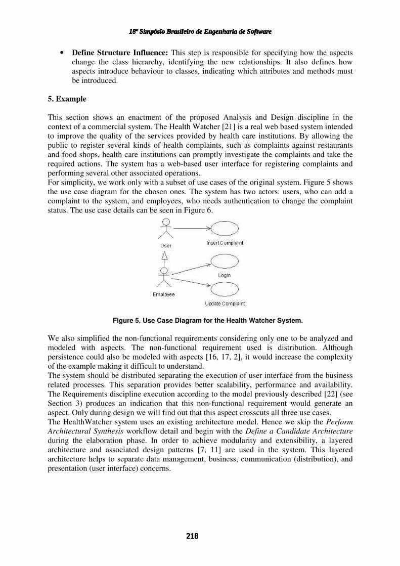
For simplicity, we work only with a subset of use cases of the original system. Figure 5 shows
the use case diagram for the chosen ones. The system has two actors: users, who can add a
complaint to the system, and employees, who needs authentication to change the complaint
status. The use case details can be seen in Figure 6.
Figure 5. Use Case Diagram for the Health Watcher System.
We also simplified the non-functional requirements considering only one to be analyzed and
modeled with aspects. The non-functional requirement used is distribution. Although
persistence could also be modeled with aspects [16, 17, 2], it would increase the complexity
of the example making it difficult to understand.
The system should be distributed separating the execution of user interface from the business
related processes. This separation provides better scalability, performance and availability.
The Requirements discipline execution according to the model previously described [22] (see
Section 3) produces an indication that this non-functional requirement would generate an
aspect. Only during design we will find out that this aspect crosscuts all three use cases.
The HealthWatcher system uses an existing architecture model. Hence we skip the Perform
Architectural Synthesis workflow detail and begin with the Define a Candidate Architecture
during the elaboration phase. In order to achieve modularity and extensibility, a layered
architecture and associated design patterns [7, 11] are used in the system. This layered
architecture helps to separate data management, business, communication (distribution), and
presentation (user interface) concerns.
218
18º Simpósio Brasileiro de Engenharia de Software18º Simpósio Brasileiro de Engenharia de Software18º Simpósio Brasileiro de Engenharia de Software18º Simpósio Brasileiro de Engenharia de Software18º Simpósio Brasileiro de Engenharia de Software18º Simpósio Brasileiro de Engenharia de Software
218218218218218
18º Simpósio Brasileiro de Engenharia de Software18º Simpósio Brasileiro de Engenharia de Software
218218
18º Simpósio Brasileiro de Engenharia de Software18º Simpósio Brasileiro de Engenharia de Software18º Simpósio Brasileiro de Engenharia de Software
218
18º Simpósio Brasileiro de Engenharia de Software18º Simpósio Brasileiro de Engenharia de Software18º Simpósio Brasileiro de Engenharia de Software

Figure 6. Use Case Details.
The Architectural Analysis during elaboration, only identifies and creates an analysis element
to represent the aspects that influence the architecture. Analysis elements should also be
created to represent the aspects indicated in requirements. Next, the Use Case Analysis
activity identifies the analysis elements according to the chosen architecture. For each
identified entity, there is a related class that represents an entity collection. In addition, each
use case has an interface and a controller. The resulting architecture with the identified
analysis elements is shown in Figure 7. For now, the distribution aspect has no relations, as
we do not know how it will affect the other analysis elements.
There are several approaches to model aspect-oriented systems [25, 24, 27, 3]. Our solution is
not attached to a particular modelling language, however we chose the aSide [3] modelling
language for it is less dependent on a programming language. The aSide modelling language
is an extension to UML to represent the aspects design. In the aSide (see Figure 7), the
diamond shape represents an aspect. The crosscutting interfaces (the way aspects crosscuts
other elements) are represented as circles attached to the aspects. The rectangle on the right
contains the crosscutting interfaces and their affecting parameters1. For simplicity, we do not
expand the aspect representation and focus only on its relationships. More details are
explained as the need arises during the example development.
1Crosscutting interfaces represent affecting roles, they may have associated parameters that represent how
theaffected class changes behaviour.
219
18º Simpósio Brasileiro de Engenharia de Software18º Simpósio Brasileiro de Engenharia de Software18º Simpósio Brasileiro de Engenharia de Software18º Simpósio Brasileiro de Engenharia de Software18º Simpósio Brasileiro de Engenharia de Software18º Simpósio Brasileiro de Engenharia de Software
219219219219219
18º Simpósio Brasileiro de Engenharia de Software18º Simpósio Brasileiro de Engenharia de Software
219219
18º Simpósio Brasileiro de Engenharia de Software18º Simpósio Brasileiro de Engenharia de Software18º Simpósio Brasileiro de Engenharia de Software
219
18º Simpósio Brasileiro de Engenharia de Software18º Simpósio Brasileiro de Engenharia de Software18º Simpósio Brasileiro de Engenharia de Software

Figure 7. Analysis Elements.
The next workflow detail is Analyze Behaviour. For a matter of space, we omit the activities
related to user interface and data base design. Hence, we start with the activity Identify Design
Elements. First, we choose to use the Facade [7] design pattern to provide a single access
point to the system business rules. Thus, the controllers used by the interface elements merge
into a single design element, which is the system facade. We also choose to use servlets to
implement the user interface. Thus, each interface element generates a servlet in the design.
The entity collections are designed with the PDC pattern [11], which consists of a structure
that uses four classes for each entity. One is the entity record, which is responsible for the
business logic related to the entity. Another is the repository interface, which is a simple
interface providing operations to store a collection of entities. It is also necessary to provide
an implementation to the repository interface. Finally, there is a class to represent the entity
itself. Thus, each entity collection originates three classes: an entity record, an interface to an
entity repository, and the repository implementation. As a consequence, we may have
different repository (persistence) implementations without affecting other parts of the system.
We choose to represent the distribution requirement with a client/server model, where the
clients are the user interface elements and the server is the system facade. As a result, we
create two design elements from the analysis aspect, one is the client aspect and the other is
the server aspect. Figure 8 shows the resulting architecture.
At this point, we carry out activity Use Case Analysis again. This time we focus on design
elements behaviour and relationships. For simplicity, we describe only what is necessary to
understand the aspects design. Starting with the server aspect, it is necessary to identify how it
will affect other classes. In a client/server model, the server should make the system façade
remote. Thus, we create a crosscutting interface (Remote) indicating that the affected object
will become remote. The other concern relative to the server aspect is to allow the necessary
objects to be transported through the remote channel. Thus, we create a second crosscutting
interface (Serializable) responsible for allowing the necessary classes to be transported
through the communication channel. Next, we associate those crosscutting interfaces with the
affected classes.
220
18º Simpósio Brasileiro de Engenharia de Software18º Simpósio Brasileiro de Engenharia de Software18º Simpósio Brasileiro de Engenharia de Software18º Simpósio Brasileiro de Engenharia de Software18º Simpósio Brasileiro de Engenharia de Software18º Simpósio Brasileiro de Engenharia de Software
220220220220220
18º Simpósio Brasileiro de Engenharia de Software18º Simpósio Brasileiro de Engenharia de Software
220220
18º Simpósio Brasileiro de Engenharia de Software18º Simpósio Brasileiro de Engenharia de Software18º Simpósio Brasileiro de Engenharia de Software
220
18º Simpósio Brasileiro de Engenharia de Software18º Simpósio Brasileiro de Engenharia de Software18º Simpósio Brasileiro de Engenharia de Software

Figure 8. Design Elements.
Figure 9 shows the resulting server aspect. Each crosscutting interface appears in the
parameter list, to indicate what class elements it affects, and it also appears as a circle
connecting the aspect and the affected class. This association also represents what class
elements are to be connected to the aspect parameters. For instance, the label <remoteOP-
>All> indicates that every operation in the class HealthWatcherFacade will be
remotely available.
Figure 9. Server Aspect.
Designing the client aspect is similar. The client aspect is initially responsible for making the
remote facade available for the user interface classes. Then, the aspect redirects calls
originally addressing the local system facade to the remote facade. Thus, the resulting aspect
has two crosscutting interfaces: the first (RemoteAccess) is associated with user interface
classes and affects its facade attribute; the second (RemoteRedirect) affects the local
system facade and redirects all the facade operations to a remote facade. The client aspect
design is shown in Figure 10.
The next workflow detail is Design Components. The only relevant activity here is Design
Aspects, which defines the necessary pointcuts and advices for the aspects. In our example,
the join points can be derived from the aspect associations. The advices indicate how the
aspect parameters affect the associated classes. For instance, the expression <remoteOp-
>All> indicates that there is one advice around all operations in the associated class. The
advice representation comes from the symbol. When it appears before the operation, it
indicates a before advice. It happens similarly when it appears after the operation. When it
221
18º Simpósio Brasileiro de Engenharia de Software18º Simpósio Brasileiro de Engenharia de Software18º Simpósio Brasileiro de Engenharia de Software18º Simpósio Brasileiro de Engenharia de Software18º Simpósio Brasileiro de Engenharia de Software18º Simpósio Brasileiro de Engenharia de Software
221221221221221
18º Simpósio Brasileiro de Engenharia de Software18º Simpósio Brasileiro de Engenharia de Software
221221
18º Simpósio Brasileiro de Engenharia de Software18º Simpósio Brasileiro de Engenharia de Software18º Simpósio Brasileiro de Engenharia de Software
221
18º Simpósio Brasileiro de Engenharia de Software18º Simpósio Brasileiro de Engenharia de Software18º Simpósio Brasileiro de Engenharia de Software

appears before and after the operation, it indicates an around advice. This activity also
identifies how the class hierarchy is affected. This happens only in our server aspect, as it
changes the ancestors of class HeathWatcherFacade to make it remote. The server may
also change the classes with the relation Serializable, making them implement this
interface to allow their serialization through the communication channel.
Figure 10. Client Aspect.
The last workflow detail is Refine the Architecture. It is responsible for unifying the design
realized by different designers. In our example, it means we would generalize our aspects to
control other user interface elements and entities. For a matter of space, we do not describe
the related activities in detail.
This concludes the elaboration phase. As mentioned earlier (see Section 4) during the
construction phase, we execute Design Components and Refine the Architecture in each
iteration to improve our existing design and incorporate possible changes to the system
requirements.
6. Conclusion
We have proposed adaptations to activities of the RUP [9] Analysis and Design discipline in
order to incorporate the concepts of AOSD. A related work [15] suggests some changes to the
roles, activities and artifacts of the Analysis and Design discipline in the presence of AOSD.
We have further developed their ideas and proposed a more precise description of the
necessary adaptations to the RUP Analysis and Design discipline. We gave an overview of
each workflow detail, proposing changes to the related activities and suggested the creation of
a new activity, Design Aspects. As far as we are aware, there is no other detailed proposal, in
the literature, for systematizing the Analysis and Design discipline, including aspects, as we
have proposed here. Another important contribution of our work is to integrate isolated efforts
towards dealing with aspects in a software process. We have adopted the work reported in
[22] for requirements, showing how the information captured at the requirements level could
be used as input to the proposed Analysis and Design discipline. We have also adopted the
modelling conventions suggested in [3].
This work focuses on one discipline defined by the RUP. Although some disciplines are not
affected by the use of AOSD, there are disciplines, other than Analysis and Design, which
need to be adapted. Hence, future work would deal with the adaptation of the Implementation
discipline as it is strongly affected by the use of AOSD and it occurs just after the Analysis
and Design discipline. One of the primary impacts is on the implementation language, which
generally is an extension to an existing language or a framework. Once the developer is used
to the new language, there are necessary adaptations to the way classes are implemented, to
incorporate aspect implementations. In a similar way, the tests should be adapted to explore
the concerns implemented by aspects.
222
18º Simpósio Brasileiro de Engenharia de Software18º Simpósio Brasileiro de Engenharia de Software18º Simpósio Brasileiro de Engenharia de Software18º Simpósio Brasileiro de Engenharia de Software18º Simpósio Brasileiro de Engenharia de Software18º Simpósio Brasileiro de Engenharia de Software
222222222222222
18º Simpósio Brasileiro de Engenharia de Software18º Simpósio Brasileiro de Engenharia de Software
222222
18º Simpósio Brasileiro de Engenharia de Software18º Simpósio Brasileiro de Engenharia de Software18º Simpósio Brasileiro de Engenharia de Software
222
18º Simpósio Brasileiro de Engenharia de Software18º Simpósio Brasileiro de Engenharia de Software18º Simpósio Brasileiro de Engenharia de Software

However, there are related problems that are discussed elsewhere. The representation of
crosscutting features in UML is discussed in [25] and the the representation of join points in
UML is discussed in [24]. The expression of aspects and its relationships to classes and other
aspects is proposed in [27], as an extension to the UML eXchange Format [26]. Finally, the
aSide Modelling Language [3] is an UML extension that allows a more abstract representation
of aspects and its relationships. We adopted this last approach to represent the aspect model in
the example (see Section 5).
RUP instantiations are common as it is an adaptable process that should be tailored to specific
companies and projects. Nevertheless, there are general instantiations that maintain the
general propose of the framework. Kruchten [10] suggests adaptations to RUP with the
objective of evolving a legacy project. Moraes [12] adapts the RUP to incorporate concepts of
the Architecture Based Development Process, which uses the architecture as a bridge between
the requirements and the implementation. Furthermore, their adaptations are mainly on the
Analysis and Design discipline.
There are also instantiations to use RUP in more specific domains. Ara´ujo and Souza [1, 23]
focused on adaptations to the Analysis and Design discipline to developWeb based
applications.
References1. Araújo, A. C. M. Framework de Análise e Projeto Baseado no RUP para o
Desenvolvimento de Aplicações Web, Master thesis, Informatics Centre – FederalUniversity of Pernambuco, February 2001.
2. Camargo, V., Ramos, R., Penteado, R., Masiero, P. C. Projeto Baseado em Aspectos doPadrão Camada de Persistência. In: XVII Brazillian Symposium on Software Engineering- SBES, October 2003.
3. Chavez, C. A Model-Driven Approach for Aspect-Oriented Design. PhD thesis, PontifíciaUniversidade Católica do Rio de Janeiro, April 2004.
4. Chung, L., Nixon, B. A., Yu, E., Mylopoulos, J. Non-Functional Requirements inSoftware Engineering, volume 5 of The Kluwer International Series In SoftwareEngineering. Kluwer Academic Publishers, October 1999.
5. D’Souza, D. F., Wills, A. C. Objects, Components, and Frameworks with UML : TheCatalysis(SM) Approach. Addison-Wesley Pub Co, October 1998.
6. Firesmith, D., Henderson-Sellers, B. The OPEN Process Framework. An Introduction.Addison-Wesley, December 2001.
7. Gamma, E., Helm, R., Johnson, R., Vlissides, J. Design Patterns: Elements of ReusableObject–Oriented Software. Addison–Wesley, 1994.
8. Kiczales, G., Lamping, J., Mendhekar, A., Maeda, C., Lopes, C., Loingtier, J.-M., Irwin,J. Aspect-oriented programming. In: Aksit, M., Matsuoka, S., editors, 11th EuropeanConf. Object-Oriented Programming, volume 1241 of LNCS, pages 220–242. SpringerVerlag, 1997.
9. Kruchten, P. The Rational Unified Process: An Introduction, Second Edition. Addison-Wesley Longman Publishing Co., Inc., 2000.
10. Kruchten, P. Using the RUP to Evolve a Legacy System. Available URL:http://www-106.ibm.com/developerworks/rational/library/389.html, May 2001, last visited in July2004.
11. Massoni, T., Alves, V., Soares, S., Borba, P. PDC: Persistent Data Collections pattern. In:First Latin American Conference on Pattern Languages Programming—SugarLoafPLoP,pages 161 – 173, Rio de Janeiro, Brazil, October 2001. UFRJ Magazine: Special Issue onSoftware Patterns.
223
18º Simpósio Brasileiro de Engenharia de Software18º Simpósio Brasileiro de Engenharia de Software18º Simpósio Brasileiro de Engenharia de Software18º Simpósio Brasileiro de Engenharia de Software18º Simpósio Brasileiro de Engenharia de Software18º Simpósio Brasileiro de Engenharia de Software
223223223223223
18º Simpósio Brasileiro de Engenharia de Software18º Simpósio Brasileiro de Engenharia de Software
223223
18º Simpósio Brasileiro de Engenharia de Software18º Simpósio Brasileiro de Engenharia de Software18º Simpósio Brasileiro de Engenharia de Software
223
18º Simpósio Brasileiro de Engenharia de Software18º Simpósio Brasileiro de Engenharia de Software18º Simpósio Brasileiro de Engenharia de Software

12. Moraes, M. A. F. Um Framework de Análise e Projeto Baseado em Arquitetura deSoftware. Master thesis, Informatics Centre – Federal University of Pernambuco, June2002.
13. Ossher, H., Kaplan, M., Katz, A., Harrison, W., Kruskal, V. Specifying subject–orientedcomposition. TAPOS, 2(3):179–202, 1996. Special Issue on Subjectivity in OO Systems.
14. Ossher, H., Tarr, P. Using subject–oriented programming to overcome common problemsin object–oriented software development/evolution. In: International Conference onSoftware Engineering, ICSE’99, pages 698–688. ACM, 1999.
15. Piveta, E. K., Devegili, A. J. Aspects in the Rational Unified Process Analysis andDesignWorkflow. In: Aspect Oriented Design Workshop, AOSD 2002, Enschende,Netherlands, 2002.
16. Rashid, A. On to aspect persistence. In: Proceedings of the Second InternationalSymposium on Generative and Component-Based Software Engineering-Revised Papers,pages 26–36. Springer-Verlag, 2001.
17. Rashid, A., Chitchyan, R. Persistence as an aspect. In: Proceedings of the 2ndinternational conference on Aspect-oriented software development, pages 120–129. ACMPress, 2003.
18. Rashid, A., Moreira, A., Araújo, J. Modularisation and composition of aspectualrequirements. In: 2nd International Conference on Aspect-Oriented SoftwareDevelopment, pages 11–20. ACM, 2003.
19. Rashid, A., Sawyer, P., Moreira, A., Araújo, J. Early aspects: A model for aspectorientedrequirements engineering. In: IEEE Joint International Conference on RequirementsEngineering, pages 199–202. IEEE, IEEE Computer Society Press, 2002.
20. Soares, S., Borba, P. PaDA: A Pattern for Distribution Aspects. In: Second LatinAmerican Conference on Pattern Languages Programming — SugarLoafPLoP, Itaipava,Rio de Janeiro, Brazil, August 2002.
21. Soares, S., Laureano, E., Borba, P. Implementing distribution and persistence aspects withAspectJ. In: Proceedings of the OOPSLA 2002 conference on Object OrientedProgramming Systems Languages and Applications, pages 174 – 190. ACM Press,November 2002.
22. Sousa, G. M. C., Silva, I. G. L., Castro, J. B. Adapting the NFR Framework to Aspect-Oriented Requirements Engineering. In: XVII Brazillian Symposium on SoftwareEngineering - SBES, October 2003.
23. Souza, R. A. C., Vasconcelos, A. M. L. Uma Extensão do Fluxo de Análise e Projeto doRUP para o Desenvolvimento de Aplicações WEB. In: XVII Brazillian Symposium onSoftware Engineering - SBES, October 2003.
24. Stein, D., Hanenberg, S., Unland, R. On representing join points in the UML. In: Kandé,M., Aldawud, O., Booch, G., Harrison, B., editors, Workshop on Aspect-OrientedModeling with UML, 2002.
25. Stein, D., Hanenberg, S., Unland, R. A uml-based aspect-oriented design notation forAspectJ. In: Proceedings of the 1st international conference on Aspect-oriented softwaredevelopment, pages 106–112. ACM Press, 2002.
26. Suzuki, J., Yamamoto, Y. Making UML models interoperable with UXF. In: Bézivin, J.,Muller, P.-A., editors, The Unified Modeling Language, UML’98 - Beyond the Notation.First International Workshop, Mulhouse, France, June 1998, Selected Papers, volume1618 of LNCS, pages 78–91. Springer, 1998.
27. Suzuki, J., Yamamoto, Y. Extending UML with aspects: Aspect support in the designphase. In: ECOOP Workshops, pages 299–300, 1999.
224
18º Simpósio Brasileiro de Engenharia de Software18º Simpósio Brasileiro de Engenharia de Software18º Simpósio Brasileiro de Engenharia de Software18º Simpósio Brasileiro de Engenharia de Software18º Simpósio Brasileiro de Engenharia de Software18º Simpósio Brasileiro de Engenharia de Software
224224224224224
18º Simpósio Brasileiro de Engenharia de Software18º Simpósio Brasileiro de Engenharia de Software
224224
18º Simpósio Brasileiro de Engenharia de Software18º Simpósio Brasileiro de Engenharia de Software18º Simpósio Brasileiro de Engenharia de Software
224
18º Simpósio Brasileiro de Engenharia de Software18º Simpósio Brasileiro de Engenharia de Software18º Simpósio Brasileiro de Engenharia de Software


