Rules for the Classification of High Speed Craft · ARTICLE 2 2.1. - Classification is the...
290
Rules for the Classification of High Speed Craft These rules have been established jointly by BUREAU VERITAS GERMANISCHER LLOYD REGISTRO ITALIANO NAVALE as Members of EEIG UNITAS NR 396 UNITAS R02 E February 2002 17 bis, Place des Reflets – La Défense 2 – 92400 Courbevoie Postal Address : 92077 Paris La Défense Cedex Tel. 33 (0) 1 42 91 52 91 – Fax. 33 (0) 1 42 91 52 93 Email: [email protected] Web: http://www.veristar.com
Transcript of Rules for the Classification of High Speed Craft · ARTICLE 2 2.1. - Classification is the...
Rules for the Classification ofHigh Speed Craft
These rules have been established jointly by
BUREAUVERITAS
GERMANISCHERLLOYD
REGISTROITALIANO NAVALE
as Members ofEEIG UNITAS
NR 396 UNITAS R02 E February 2002
17 bis, Place des Reflets – La Défense 2 – 92400 CourbevoiePostal Address : 92077 Paris La Défense Cedex
Tel. 33 (0) 1 42 91 52 91 – Fax. 33 (0) 1 42 91 52 93Email: [email protected]
Web: http://www.veristar.com

MARINE DIVISION GENERAL CONDITIONS
BV Mod. Ad. ME 545 h - 06/2000
ARTICLE 1
1.1. - BUREAU VERITAS is a Society the purpose of whose Marine Division (the“Society”) is the classification (« Classification ») of any ship or vessel or structure of anytype or part of it or system therein collectively hereinafter referred to as a “Unit” whetherlinked to shore, river bed or sea bed or not, whether operated or located at sea or ininland waters or partly on land, including submarines, hovercrafts, drilling rigs, offshoreinstallations of any type and of any purpose, their related and ancillary equipment, subseaor not, such as well head and pipelines, mooring legs and mooring points or otherwise asdecided by the Society.The Society:• prepares and publishes Rules for classification, Guidance Notes and other
documents (« Rules »);• issues Certificates, Attestations and Reports following its interventions
(« Certificates »);• publishes Registers.
1.2. - The Society also participates in the application of National and InternationalRegulations or Standards, in particular by delegation from different Governments. Thoseactivities are hereafter collectively referred to as « Certification ».
1.3. - The Society can also provide services related to Classification and Certificationsuch as ship and company safety management certification; training activities; allactivities and duties incidental thereto such as documentation on any supporting means,software, instrumentation, measurements, tests and trials on board.
1.4. - The interventions mentioned in 1.1., 1.2. and 1.3. are referred to as « Services ».The party and/or its representative requesting the services is hereinafter referred to as the« Client ».
The Services are prepared and carried out on the assumption that the Clients areaware of the International Maritime and/or Offshore Industry (the “Industry”)practices.
1.5. - The Society is neither and may not be considered as an Underwriter, Broker inship’s sale or chartering, Expert in Unit’s valuation, Consulting Engineer, Controller, NavalArchitect, Manufacturer, Shipbuilder, Repair yard, Charterer or Shipowner who are notrelieved of any of their expressed or implied obligations by the interventions of theSociety.
ARTICLE 2
2.1. - Classification is the appraisement given by the Society for its Client, at a certaindate, following surveys by its Surveyors along the lines specified in Articles 3 and 4hereafter on the level of compliance of a Unit to its Rules or part of them. Thisappraisement is represented by a class entered on the Certificates and periodicallytranscribed in the Society’s Register.
2.2. - Certification is carried out by the Society along the same lines as set out in Articles3 and 4 hereafter and with reference to the applicable National and InternationalRegulations or Standards.
2.3. - It is incumbent upon the Client to maintain the condition of the Unit aftersurveys, to present the Unit for surveys and to inform the Society wit hout delay ofcircumstances which may affect the given appraisement or cause to modify itsscope.
2.4. - The Client is to give to the Society all access and information necessary for theperformance of the requested Services.
ARTICLE 3
3.1. - The Rules, procedures and instructions of the S ociety t ake into a ccount at thedate of their preparation the state of currently available and proven technicalknowledge of the Industry. They are not a code of construction neither a guide formaintenance or a safety handbook.
Committees consisting of personalities from the Industry contribute to the development ofthose documents.
3.2. - The Society only is qualified to apply its Rules and to interpret them. Anyreference to them is void unless it involves the S ociety’s intervention.
3.3. - The Services of the Society are carried out by professional Surveyors according tothe Code of Ethics of the Members of the International Association of ClassificationSocieties (IACS).
3.4. - The operations of the Society in providing its Services make use of randominspections and are absolutely exclusive of any monitoring and thorough verification.
ARTICLE 4
4.1. - The Society, acting by reference to its Rules:• reviews the construction arrangements of the Units as shown on the documents
presented by the Client;• conducts surveys at the place of their construction;• classes Units and enters their name in its Register;• surveys periodically the Units in service to note that the requirements for the
maintenance of class are met.
The Client is to inform the Soc iety without delay of circumstan ces which may causethe date or the extent of the surveys to be ch anged.
ARTICLE 5
5.1. - The Society acts as a provider of services. This ca nnot be construed as anobligation bearing on the Society to obtain a result or in a warranty.
5.2. - The certificates issued by the Society pursuant to 5.1. here above are astatement on the level of compliance of the Unit to its Rules or to the documents ofreference for the Services provided for.
In particular, the Society does not engage in any work relating to the design,building, production or repair c hecks, neither in the operation of the Units or in theirtrade, neither in any advisory services, and ca nnot be held liable on those accounts.Its certificates cannot be construed as an implied or expr ess warranty of safety,fitness for the purpose, seaworth iness of the Unit or of its value for sale, insuranceor chartering.
5.3. - The Society does not declare the acceptance or commissioning of a Unit, thatbeing the exclusive responsib ility of its owner.
5.4. - The Services of the Society ca nnot create any obligation bearing on theSociety or constitute any warranty of proper operation, beyond any repr esentationset forth in the Rules, of any Unit, equipment or machinery, compu ter software of anysort or other comparable concepts that has been subject to any survey by theSociety.
ARTICLE 6
6.1. - The Society accepts no responsibility for the use of information related to itsServices which was not provided for the purpose by the Society or with its assistance.
6.2. - If the Services of the Society cause to the Client a damage which is proved tobe the direct and reasonably foreseeable consequence of an error or o mission of theSociety, its liability towards the Client is limited to ten times the am ount of fee paidfor the Service having caused the damage. This limit is subject to a mini mum of fiftythousand (50.000) French francs, and to a maximum which is the greater of fivemillions (5.000.000) French francs and one and a half times the above mentioned fee.
The Society bears no liability for indirect or consequential loss such as e.g. loss ofrevenue, loss of profit, loss of production, loss relative to other contracts andindemnities for termination of other agreements.
6.3. - All claims are to be presented to the Society in writing and on pain ofdebarment by right, within three months of the date the Services were supplied or ofthe date the events which are t aken advantage of were first known.
ARTICLE 7
7.1. - Requests for Services are to be in writing.
7.2. - Either the Client or the Society can terminate as of right the requested Servicesby prior written notice according to paragraph 7.3., for convenience, and wit houtprejudice to the provisions in Article 8 hereunder.
7.3. - The notice due by the Society to the Client to exercise the possib ility under 7.2.is of three calendar months and conversely, of ten banking days.
7.4. - The class granted to the concerned Units and the previously issued certificatesremain valid until the date of effect of the notice issued according to 7.2. hereabovesubject to compliance with 2.3. hereabove and Article 8 hereunder.
ARTICLE 8
8.1. - The Services of the Society, whether completed or not, involve the payment of feeupon receipt of the invoice and the reimbursement of the expenses incurred.
8.2. - The class of a Unit may be suspended in the event of non-payment of fee after afirst unfruitful notification to pay.
ARTICLE 9
9.1. - The documents and data provided to or prepared by the Society for its Services, andthe information available to the Society, are treated as confidential. However:• Clients have access to the data they have provided to the Society and to the reports
and certificates which have been prepared for them;• copy of the documents made available for the classification of the Unit can be
handed over to another Classification Society Member of the InternationalAssociation of Classification Societies (IACS) in case of the Unit’s transfer of class;
• the data relative to the evolution of the Register, to the class suspension and to thesurvey status of the Units are passed on to IACS according to the associationworking rules;
• technical records and history related to specific class notations may be transferred tothe new owner in case of change of ownership;
• the certificates, documents and information relative to the Units classed with theSociety are passed on upon order of the flag authorities of the Unit or of a Courthaving jurisdiction.
The documents and data are subject to a file management plan.
ARTICLE 10
10.1. - Any delay or shortcoming in the performance of its Services by the Society arisingfrom an event not reasonably foreseeable by or beyond the control of the Society shall bedeemed not to be a breach of contract.
ARTICLE 11
11.1. - The Society may designate another Surveyor at the request of the Client in case ofdiverging opinions during surveys.
11.2. - Disagreements of a technical nature between the Client and the Society can besubmitted by the Society to the advice of its Classification Committee.
ARTICLE 12
12.1. - Disputes over the Services carried out by delegation of Governments are assessedwithin the framework of the applicable agreements with the States, internationalConventions and national rules.
12.2. - Disputes arising out of the payment of the Society’s invoices by the Client aresubmitted to the Court of Nanterre, France.
12.3. - Other disputes over the present General C onditions or over the Servi ces ofthe Society are exclusively submitted to arbitration in London according to theLondon arbitration procedural r ules in force. English law applies.
ARTICLE 13
13.1. - These General C onditions constitute the sole contractual obligations bindingtogether the Society and the Client, to the exclusion of all other representation,statements, terms, conditions whether expr ess or implied. They may be varied inwriting by mutual agreement.
13.2. - The invalidity of one or more stipulations of the present General Conditions doesnot affect the validity of the remaining provisions.
13.3. - The definitions herein take precedence over any definitions serving the samepurpose which may appear in other documents issued by the Society.
RULES FOR THE CLASSIFICATION
OF HIGH SPEED CRAFT
Premise
Preamble of the International Code of Safety for High-Speed Craft, 2000
Chapter 1 General Comments and Requirements
Chapter 2 Buoyancy, Stability and Subdivision
Chapter 3 Structures
Chapter 4 Accommodation and Escape Measures
Chapter 5 Directional Control Systems
Chapter 6 Anchoring, Towing and Berthing
Chapter 7 Fire Safety
Chapter 8 Life-Saving Appliances and Arrangements
Chapter 9 Machinery
Chapter 10 Auxiliary Systems
Chapter 11 Remote Control, Alarm and Safety Systems
Chapter 12 Electrical Installations
Chapter 13 Shipborne Navigational Systems and Equipment and Voyage Data Recorders
Chapter 14 Radiocommunications
Chapter 15 Operating Compartment Layout
Chapter 16 Stabilization Systems
Chapter 17 Handling, Controllability and Performance
Chapter 18 Operational Requirements
Chapter 19 Inspection and Maintenance Requirements
Annex 1 Form of High-Speed Craft Safety Certificate and Record of Equipment
Annex 2 Form of Permit to Operate High-Speed Craft
Annex 3 Use of Probability Concept
Annex 4 Procedures for Failure Mode and Effects Analysis
Annex 5 Ice Accretion Applicable to All Types of Craft
Annex 6 Stability of Hydrofoil Craft
Annex 7 Stability of Multihull Craft
Annex 8 Stability of Monohull Craft
Annex 9 Definitions, Requirements and Compliance Criteria Related to Operational and SafetyPerformance
Annex 10 Criteria for Testing and Evaluation of Revenue and Crew Seats
Annex 11 Open Reversible Liferafts
February 2002

2 Bureau Veritas February 2002
Unless otherwise specified, these rules apply to ships for which contracts are signed after April 30th, 2002. The Society may refer to the contents hereof before April 30th, 2002 at the special request of the party applying for classification.
HSC Table of Contents
Table of Contents
Premise
P.1 General 11P.2 Application 11P.3 Class notation 12P.4 Compliance with other rules 12P.5 Novel or unusual features 12
Preamble of the International Code of Safety for High-Speed Craft, 2000
Chapter 1 General Comments and Requirements
1.1 General comments 151.2 General requirements 151.3 Application 151.4 Definitions 161.5 Surveys 201.6 Approvals 211.7 Maintenance of conditions after survey 211.8 High-Speed Craft Safety Certificate 211.9 Permit to Operate High-Speed Craft 22
1.10 Control 231.11 Equivalents 231.12 Information to be made available 231.13 Further developments 231.14 Circulation of safety information 241.15 Review of the code 24
Chapter 2 Buoyancy, Stability and Subdivision
C2.0 Documents to be submitted 252.1 General 252.2 Intact buoyancy and watertight and weathertight integrity 262.3 Intact stability in the displacement mode 312.4 Intact stability in the non-displacement mode 312.5 Intact stability in the transitional mode 322.6 Buoyancy and stability in the displacement mode following damage 322.7 Inclining and stability information 342.8 Loading and stability assessment 352.9 Marking and recording of the design waterline 35
2.10 General 362.11 Intact stability in the displacement mode 362.12 Intact stability in the non-displacement mode 362.13 Buoyancy and stability in the displacement mode following damage 362.14 Inclining and stability information 362.15 Buoyancy and stability in the displacement mode following damage 382.16 Inclining 38
February 2002 Bureau Veritas 3
HSC Table of Contents
Chapter 3 Structures
C3.0 Documents to be submitted 393.1 General 403.2 Materials 403.3 Structural strength 403.4 Cyclic loads 403.5 Design criteria 403.6 Trials 40
C3.1 General 40C3.2 Materials and connections 42C3.3 Design acceleration 51C3.4 Overall loads 54C3.5 Local loads 58C3.6 Direct calculations for monohulls and catamarans 62C3.7 Steel and aluminium alloy craft 66C3.8 Fibre-reinforced plastic craft 87C3.9 Hull appendages 100
C3.10 Rudders 102C3.11 Stabilisation means 109
C3A1.1 Foreword 110C3A1.2 General 110C3A1.3 Definitions and symbols 110C3A1.4 Documents to be submitted 110C3A1.5 Longitudinal strength 111C3A1.6 Local strength 111C3A1.7 Foils 114C3A2.1 Foreword 116C3A2.2 General 116C3A2.3 Documents to be submitted 117C3A2.4 Scantlings criteria 117C3A2.5 Load factors 120C3A2.6 Strength limits and safety coefficients 121C3A2.7 Cases of scantlings 121C3A2.8 Allowable stresses 123C3A2.9 Distortions 123
Chapter 4 Accommodation and Escape Measures
C4.0 Documents to be submitted 1244.1 General 1244.2 Public address and information system 1244.3 Design acceleration levels 1254.4 Accommodation design 1264.5 Seating construction 1274.6 Safety belts 1274.7 Exits and means of escape 1274.8 Evacuation time 1284.9 Baggage, stores, shops and cargo compartments 129
4.10 Noise levels 1304.11 Protection of the crew and passengers 130
4 Bureau Veritas February 2002

HSC Table of Contents
Chapter 5 Directional Control Systems
C5.0 Documents to be submitted 1315.1 General 1315.2 Reliability 1315.3 Demonstrations 1335.4 Control position 133
Chapter 6 Anchoring, Towing and Berthing
C6.0 Documents to be submitted 1346.1 General 1346.2 Anchoring 1346.3 Towing 1346.4 Berthing 134
C6.5 Equipment 135
Chapter 7 Fire Safety
C7.0 Documents to be submitted 1417.1 General Requirements 1417.2 Definitions 1427.3 Classification of space use 1427.4 Structural fire protection 1437.5 Fuel and other flammable fluid tanks and systems 1477.6 Ventilation 1487.7 Fire detection and extinguishing systems 1497.8 Protection of special category spaces and ro-ro spaces 1547.9 Miscellaneous 156
7.10 Firefighter's outfits 1577.11 Arrangement 1587.12 Ventilation 1587.13 Fixed sprinkler system 1587.14 Control stations 1597.15 Cargo spaces 1597.16 Fixed sprinkler system 1597.17 General 160
Chapter 8 Life-Saving Appliances and Arrangements
8.1 General and definitions 1648.2 Communications 1658.3 Personal life-saving appliances 1658.4 Muster list, emergency instructions and manuals 1668.5 Operating instructions 1668.6 Survival craft stowage 1678.7 Survival craft and rescue boat embarkation and recovery arrangements 1678.8 Line-throwing appliance 1688.9 Operational readiness, maintenance and inspections 168
8.10 Survival craft and rescue boats 1708.11 Helicopter pick-up areas 170
February 2002 Bureau Veritas 5
HSC Table of Contents
Chapter 9 Machinery
9.1 General 1719.2 Engine (general) 1749.3 Gas turbines 1749.4 Diesel engines for main propulsion and essential auxiliaries 1759.5 Transmissions 1779.6 Propulsion and lift devices 1789.7 Independent means of propulsion for category B craft 1799.8 Means for return to a port of refuge for category B craft 1799.9 Essential machinery and control 179
Chapter 10 Auxiliary Systems
C10.0 Documents to be submitted 18010.1 General 18010.2 Arrangement of oil fuel, lubricating oil and other flammable oil 18810.3 Bilge pumping and drainage systems 19110.4 Ballast systems 19210.5 Cooling systems 19310.6 Engine air intake systems 19310.7 Ventilation systems 19310.8 Exhaust systems 194
C10.A.1 Compressed air systems 194C10.A.2 Steam heating, feedwater and condensate systems 195C10.A.3 Air, overflow and sounding pipes 196C10.A.4 Drinking water systems 196C10.A.5 Sanitary systems 196C10.A.6 Hydraulic systems for hatch covers, shell closing appliances,
watertight doors and hoists 19710.9 Bilge pumping and drainage systems 199
C10.B.1 Operating systems for watertight doors 19910.10 Bilge pumping systems 199
C10.C.1 Hydraulic operating systems for watertight doors 199
Chapter 11 Remote Control, Alarm and Safety Systems
C11.0 Documents to be submitted 20011.1 Definitions 20011.2 General 20011.3 Emergency controls 20111.4 Alarm system 20211.5 Safety system 203
C11.6 Stand-by systems 204
Chapter 12 Electrical Installations
C12.0 Documents to be submitted 20512.1 General 20512.2 Main source of electrical power 20612.3 Emergency source of electrical power 20812.4 Starting arrangements for emergency generating sets 20912.5 Steering and stabilization 209
6 Bureau Veritas February 2002
HSC Table of Contents
12.6 Precautions against shock, fire and other hazards of electrical origin 21012.7 General 21312.8 General 216
Chapter 13 Shipborne Navigational Systems and Equipment and Voyage DataRecorders
13.1 General 21813.2 Compasses 21813.3 Speed and distance measurement 21813.4 Echo-sounding device 21813.5 Radar installations 21813.6 Electronic positioning systems 21913.7 Rate-of-turn indicator and rudder angle indicator 21913.8 Nautical charts and nautical publications 21913.9 Searchlight and daylight signalling lamp 219
13.10 Night vision equipment 21913.11 Steering arrangement and propulsion indicator(s) 21913.12 Automatic steering aid (automatic pilot) 21913.13 Radar reflector 21913.14 Sound reception system 22013.15 Automatic identification system 22013.16 Voyage data recorder 22013.17 Approval of systems and equipment, and performance standards 220
C13.18 Electric power supply-distribution panels 221
Chapter 14 Radiocommunications
14.1 Application 22214.2 Terms and definitions 22214.3 Exemptions 22314.4 Global maritime distress and safety system identities 22314.5 Functional requirements 22314.6 Radio installations 22314.7 Radio equipment: general 22414.8 Radio equipment: sea area A1 22514.9 Radio equipment: sea areas A1 and A2 225
14.10 Radio equipment: sea areas A1, A2 and A3 22614.11 Radio equipment: sea areas A1, A2, A3 and A4 22714.12 Watches 22714.13 Sources of energy 22714.14 Performance standards 22814.15 Maintenance requirements 22914.16 Radio personnel 22914.17 Radio records 22914.18 Position-updating 229
Chapter 15 Operating Compartment Layout
15.1 Definitions 23015.2 General 23015.3 Field of vision from the operating compartment 23015.4 Operating compartment 230
February 2002 Bureau Veritas 7

HSC Table of Contents
15.5 Instruments and chart table 23115.6 Lighting 23215.7 Windows 23215.8 Communication facilities 23215.9 Temperature and ventilation 232
15.10 Colours 23215.11 Safety measures 232
Chapter 16 Stabilization Systems
16.1 Definitions 23316.2 General requirements 23316.3 Lateral and height control systems 23316.4 Demonstrations 234
Chapter 17 Handling, Controllability and Performance
17.1 General 23517.2 Proof of compliance 23517.3 Weight and centre of gravity 23517.4 Effect of failures 23517.5 Controllability and manœuvrability 23517.6 Change of operating surface and mode 23617.7 Surface irregularities 23617.8 Acceleration and deceleration 23617.9 Speeds 236
17.10 Minimum depth of water 23617.11 Hard structure clearance 23617.12 Night operation 236
Chapter 18 Operational Requirements
C18.0 Documents to be submitted 23718.1 Craft operational control 23718.2 Craft documentation 23818.3 Training and qualifications 24018.4 Manning of survival craft and supervision 24118.5 Emergency instructions and drills 24218.6 Type rating training 24318.7 Emergency instructions and drills 24318.8 Type rating training 244
Chapter 19 Inspection and Maintenance Requirements
Annex 1 Form of High-Speed Craft Safety Certificate and Record of Equipment
Annex 2 Form of Permit to Operate High-Speed Craft
8 Bureau Veritas February 2002
HSC Table of Contents
Annex 3 Use of Probability Concept
1 General 2582 Terms associated with probabilities 2583 Numerical values 260
Annex 4 Procedures for Failure Mode and Effects Analysis
C0 Document to be submitted 2621 Introduction 2622 Objectives 2623 Scope of application 2624 System failure mode and effects analysis 2635 Equipment failure mode and effects analysis 2636 Procedures 2637 System definition 2648 Development of system block diagrams 2649 Identification of failure modes, causes and effects 264
10 Failure effects 26411 Failure detection 26512 Corrective measures 26513 Use of probability concept 26514 Documentation 26515 Test programme 26616 FMEA Report 266
Annex 5 Ice Accretion Applicable to All Types of Craft
1 Icing allowances 2692 Areas of icing conditions 2693 Special requirements 269
Annex 6 Stability of Hydrofoil Craft
1 Surface-piercing hydrofoils 2712 Fully submerged hydrofoils 272
Annex 7 Stability of Multihull Craft
1 Stability criteria in the intact condition 2742 Criteria for residual stability after damage 2753 Application of heeling levers 276
Annex 8 Stability of Monohull Craft
1 Stability criteria in the intact condition 2772 Criteria for residual stability after damage 277
February 2002 Bureau Veritas 9
HSC Table of Contents
Annex 9 Definitions, Requirements and Compliance Criteria Related toOperational and Safety Performance
1 Performance 279
2 Stopping 279
3 Cruise performance 280
4 Effects of failures or malfunction 281
Annex 10 Criteria for Testing and Evaluation of Revenue and Crew Seats
1 Purpose and scope 282
2 Static seat tests 282
3 Dynamic seat tests 282
Annex 11 Open Reversible Liferafts
1 General 284
2 Construction 284
3 Open reversible liferaft fittings 285
4 Containers for open reversible inflatable liferafts 286
5 Markings on open reversible inflatable liferafts 286
6 Instructions and information 286
7 Testing of open reversible inflatable liferafts 287
10 Bureau Veritas February 2002

RULES FOR THE CLASSIFICATION
OF HIGH SPEED CRAFT
PREMISE
P.1 General
P.1.1
.1 These rules incorporate the text in full of the “International Code of Safety for High Speed Craft” (“HSC Code”)adopted by the IMO Maritime Safety Committee, at its 73rd session, in December 2000, through Resolution MSC. 97(73). Thistext is printed in italics.
.2 Classification requirements additional to the provisions of the HSC Code are printed in the Roman charactersused for this item .2 and the relevant number is prefixed by the letter C.In Chapter 10, which is subdivided into Parts, additional classification requirements not directly related to a particular HSCCode item are numbered as follows: prefix C, Chapter number, letter indicating the Part concerned and an incremental figurestarting from 1. These additional requirements are inserted at the end of the relevant Part of the Chapter.Where necessary, additional explanatory notes are given at the beginning of each Chapter.
.3 Parts of the HSC Code not applicable for the purpose of classification are identified by a vertical line placed inthe margin of the text.
.4 Equipment and arrangements dealt with in the parts of the Code mentioned in item .3, such as those concerninglife-saving appliances and radiocommunications, which are not subject to control by the Society, are intended to be covered bythe relevant certification.
P.1.2 In those provisions of the HSC Code that are being used for classification purposes the words “Administration”and “Code”, wherever mentioned, are to be understood as equivalent to the words “Society” and “Rules”, respectively.
The Rules for the construction and classification of ships are referred to below simply as “Society Rules”.
P.2 Application
P.2.1 Craft for which classification only is requested
These craft are to comply in full with the requirements of these rules, except for those identified by a vertical line placed in themargin of the text (see P.1.1.3).
P.2.2 Craft for which both classification and the IMO Certification are requested
These craft are to comply in full with the requirements of these rules.
February 2002 Bureau Veritas 11
HSC Premise
P.3 Class notation
Craft complying with the classification requirements of these Rules are assigned the notation HSC or High Speed Craft, com-pleted as specified in the Society Rules.
P.4 Compliance with other rules
For any items not expressly stipulated or modified for classification purposes by these Rules, the requirements of the SocietyRules are to apply wherever relevant.Classification of a craft with the Society, or more generally any Society actions and decisions, do not absolve the interested par-ties from compliance with additional and/or more stringent requirements and provisions for their application, issued by theAdministration of the State whose flag the craft is entitled to fly and/or of the State where the base port from which the craft isintended to operate is situated.
P.5 Novel or unusual features
Craft presenting novel or unusual arrangements for items such as systems, apparatuses and devices, described in these rules, towhich the requirements of these rules do not apply directly, either in whole or on part, may be classed on an individual basis, atthe discretion of the Society.
12 Bureau Veritas February 2002

PREAMBLE OF THE
INTERNATIONAL CODE OF SAFETY FOR
HIGH-SPEED CRAFT, 2000
1 The international conventions ratified in respect of conventional ships and the regulations applied as a consequence ofsuch conventions have largely been developed having in mind the manner in which conventional ships are constructed andoperated. Traditionally, ships have been built of steel and with the minimum of operational controls. The requirements for shipsengaged on long international voyages are therefore framed in such a way that, providing the ship is presented for survey and aShip Safety Certificate is issued, the ship may go anywhere in the world without any operational restrictions being imposed. Pro-viding the ship is not involved in a casualty, all that is needed is that it is made available to the Administration for the purpose ofa satisfactory resurvey before the Ship Safety Certificate expires and the Certificate will be reissued.
2 The traditional method of regulating ships should not be accepted as being the only possible way of providing anappropriate level of safety. Nor should it be assumed that another approach, using different criteria, could not be applied. Overa long period of time, numerous new designs of marine vehicles have been developed and have been in service. While these donot fully comply with the provisions of the international conventions relating to conventional ships built of steel, they have dem-onstrated an ability to operate at an equivalent level of safety when engaged on restricted voyages under restricted operationalweather conditions and with approved maintenance and supervision schedules.
3 The High-Speed Craft Code 1994 (1994 HSC Code) was derived from the previous Code of Safety for DynamicallySupported Craft (DSC Code) adopted by IMO in 1977, recognizing that safety levels can be significantly enhanced by the infra-structure associated with regular service on a particular route, whereas the conventional ship safety philosophy relies on theship being self-sustaining with all necessary emergency equipment being carried on board.
4 The safety philosophy of this Code is based on the management and reduction of risk as well as the traditional philoso-phy of passive protection in the event of an accident. Management of risk through accommodation arrangement, active safetysystems, restricted operation, quality management and human factors engineering should be considered in evaluating safetyequivalent to current conventions. Application of mathematical analysis should be encouraged to assess risk and determine thevalidity of safety measures.
5 This Code takes into account that a high-speed craft is of a light displacement compared with a conventional ship. Thisdisplacement aspect is the essential parameter to obtain fast and competitive sea transportation and consequently this Codeallows for use of non-conventional shipbuilding materials, provided that a safety standard at least equivalent to conventionalships is achieved.
6 To clearly distinguish such craft, criteria based on speed and volumetric Froude number have been used to delineatethose craft to which this Code applies from other, more conventional, craft.
7 The Code requirements also reflect the additional hazards which may be caused by the high speed compared withconventional ship transportation. Thus, in addition to the normal requirements (including life-saving appliances, evacuationfacilities, etc.) provided in case of an accident occurring, further emphasis is placed on reducing the risk of hazardous situationsarising. Some advantages result from the high-speed craft concept, i.e. the light displacement provides a large reserve buoyancyin relation to displacement, reducing the hazards addressed by the International Convention on Load Lines, 1966. The conse-quences of other hazards, such as of collision at high speed, are balanced by more stringent navigational and operationalrequirements and specially developed accommodation provisions.
February 2002 Bureau Veritas 13
Preamble of the International Code of Safety for High-Speed Craft, 2000
8 The above-mentioned safety concepts were originally reflected in the DSC Code and in the 1994 HSC Code. Thedevelopment of novel types and sizes of craft has led to the development of pressures within the maritime industry for craftwhich are not dynamically supported cargo craft or passenger craft carrying larger numbers of passenger or operating furtherafield than permitted by that Code to be certified according to those concepts. Additionally, improvements of maritime safetystandards since 1994 were required to be reflected in the revisions of the 1994 HSC Code to maintain safety equivalence withconventional ships.
9 Accordingly, two differing principles of protection and rescue were embodied in the 1994 HSC Code.
10 The first of these recognizes the craft which were originally foreseen at the time of development of the DSC Code.Where rescue assistance is readily available and the total number of passengers is limited, a reduction in passive and active pro-tection may be permitted. Such craft are called “assisted craft” and form the basis for “category A passenger craft” of this Code.
11 The second concept recognizes the further development of high-speed craft into larger craft. Where rescue assistance isnot readily available or the number of passengers is unlimited, additional passive and active safety precautions are required.These additional requirements provide for an area of safe refuge on board, redundancy of vital systems, increased watertightand structural integrity and full fire-extinguishing capability. Such craft are called “unassisted craft” and form the basis for “cargocraft” and “category B passenger craft” of this Code.
12 These two concepts have been developed as a unified document on the basis that an equivalent level of safety to thatnormally expected on ships complying with the International Convention for the Safety of Life at Sea, 1974 is achieved. Wherethe application of new technology or design indicates an equivalent safety level to the strict application of this Code, the Admin-istration is permitted to formally recognize such equivalence.
13 It is important that an Administration, in considering the suitability of a high-speed craft under this Code, should applyall sections of the Code because non-compliance with any part of the Code could result in an imbalance which would adverselyaffect the safety of the craft, passengers and crew. For a similar reason, modifications to existing craft, which may have an effecton safety, should be approved by the Administration.
14 In developing this Code, it has been considered desirable to ensure that high-speed craft do not impose unreasonabledemands on existing users of the environment or conversely suffer unnecessarily through lack of reasonable accommodation byexisting users. Whatever burden of compatibility there is, it should not necessarily be laid wholly on the high-speed craft.
15 Paragraph 1.15.1 of the 1994 HSC Code states that it should be reviewed by the Organization at intervals preferablynot exceeding 4 years to consider revision of existing requirements to take account of new developments in design and technol-ogy. Experience gained with the application of the 1994 HSC Code since it entered into force in 1996 has led to the recognitionthat it needed to be revised and updated. Subsequent work in the Organization has resulted in the development of the presentCode to ensure that safety is not compromised as a result of continuous introduction of state-of-the-art technology and innova-tive developments into the new and generally much larger and faster high-speed craft.
14 Bureau Veritas February 2002
HSC Chapter 1
CHAPTER 1 GENERAL COMMENTS AND REQUIREMENTS
1.1 General comments
This Code shall be applied as a complete set of comprehen-sive requirements. It contains requirements for the designand construction of high-speed craft engaged on interna-tional voyages, the equipment which shall be provided andthe conditions for their operation and maintenance. Thebasic aim of the Code is to set levels of safety which areequivalent to those of conventional ships required by theInternational Convention for the Safety of Life at Sea, 1974,as amended, (SOLAS Convention) and the InternationalConvention on Load Lines, 1966, (Load Line Convention)by the application of constructional and equipment stand-ards in conjunction with strict operational controls.
Note: Refer to MSC/Circ.652 on Application of the 1966 LL Con-vention to high-speed craft.
C1.1(a) The attention of Shipowners, Shipdesigners andFlag Administrations is drawn to the innovative aspects ofdesigns of High Speed Craft.
The present Rules may need to be adapted to cover particu-lar designs.
It is assumed as a condition precedent to classification thatthe craft are operated with professional care and normalprudent seamanship.
C1.1(b) Craft satisfying the requirements of these Rules areassigned the notation HSC or High Speed Craft.
1.2 General requirements
The application of the provisions of this Code is subject tothe following general requirements that:
.1 the Code will be applied in its entirety;
.2 the management of the company operatingthe craft exercises strict control over its operation and main-tenance by a quality-management system
Note: Refer to the International Safety Management (ISM) Codeadopted by the Organization by resolution A.741(18), as may beamended.
.3 the management ensures that only personsqualified to operate the specific type of craft used on theintended route are employed;
.4 the distances covered and the worstintended conditions in which high-speed craft operationsare permitted will be restricted by the imposition of opera-tional limits;
.5 the craft will at all times be in reasonableproximity to a place of refuge, having due regard to the pro-visions of 1.3.4;
.6 adequate communications facilities, weatherforecasts and maintenance facilities are available within thearea of craft operation;
.7 in the intended area of operation suitable res-cue facilities will be readily available;
.8 areas of high fire risk, such as machineryspaces and special category spaces, are protected with fire-resistant materials and fire-extinguishing systems to ensure,as far as is practicable, containment and rapid extinguishingof fire;
.9 efficient facilities are provided for the rapidand safe evacuation of all persons into survival craft;
.10 all passengers and crew are provided withseats;
.11 no enclosed sleeping berths for passengersare provided.
C1.2 (a) With reference to 1.2.2, craft managed by compa-nies operating with a Safety Management System comply-ing with the Society Rules are assigned a special notation.To this effect, the relevant requirements of Chapters 18 and19 are to be checked. This notation is entered in the ClassCertificate and the Register Book.
C1.2 (b) The limitations on navigation indicated in 1.2.4and 1.2.5 are subject to specific navigation/restriction nota-tions in Society Rules.
1.3 Application
1.3.1 This Code applies to high speed craft asspecified in 1.3.4 engaged in international voyages the keelsof which are laid or which are at a similar stage of construc-tion on or after 1 July 2002.
February 2002 Bureau Veritas 15

HSC Chapter 1
C1.3.1 In addition to the craft specified in 1.3.1,these Rules also apply to high speed craft engaged innational voyages. Exemptions from some of the require-ments of the Rules may be granted when particularcircumstances (e.g. restricted services) warrant this, in theopinion of the Society Head Office.
1.3.2 For the purpose of this Code, the term “asimilar stage of construction” means the stage at which:
.1 construction identifiable with a specific craftbegins; and
.2 assembly of that craft has commenced com-prising at least 50 tonnes or three per cent of the estimatedmass of all material used in the structure, including super-structure and deckhouse, whichever is less.
1.3.3 For the purpose of this Code:
.1 the expression “craft constructed” meanscraft the keels of which are laid or which are at a similarstage of construction; and
.2 a cargo craft, whenever built, which is con-verted to a passenger craft shall be treated as a passengercraft constructed on the date on which such a conversioncommences.
1.3.4 This Code applies to:
.1 passenger craft which do not proceed in thecourse of their voyage more than four hours at operationalspeed from a place of refuge; and
.2 cargo craft of 500 gross tonnage andupwards which do not proceed in the course of their voy-age more than 8 h at operational speed from a place ofrefuge when fully laden.
C1.3.4 In addition to the cargo craft specified in1.3.4.2, these Rules also apply as far as appropriate to cargocraft of less than 500 tons gross tonnage.
1.3.5 This Code, unless expressly provided other-wise, does not apply to:
.1 craft of war and troopcraft;
.2 craft not propelled by mechanical means;
.3 wooden craft of primitive build;
.4 pleasure craft not engaged in trade; and
.5 fishing craft.
C1.3.5 However, classification may be consideredfor craft referred to in 1, 2, 4 and 5 above.
1.3.6 This Code does not apply to craft solely navi-gating the Great Lakes of North America and the River St.Lawrence as far east as a straight line drawn from Cap desRosiers to West Point, Anticosti Island and, on the northside of Anticosti Island, the 63rd meridian.
1.3.7 The application of this Code shall be verifiedby the Administration and be acceptable to the Govern-ments of the States to which the craft will be operating.
C1.3.7 The Classification of a craft, or more gener-ally any Society acts and decisions, do not absolve theinterested parties from compliance with any additionaland/or more stringent requirements issued by the Adminis-tration of the State whose flag the craft is entitled to fly, andprovisions for their application.
1.4 Definitions
For the purpose of this Code, unless expressly provided oth-erwise, the terms used therein have the meanings defined inthe following paragraphs. Additional definitions are given inthe general parts of the various chapters.
1.4.1 “Administration” means the Government ofthe State whose flag the craft is entitled to fly.
1.4.2 “Air-cushion vehicle (ACV)” is a craft suchthat the whole or a significant part of its weight can be sup-ported, whether at rest or in motion, by a continuouslygenerated cushion of air dependent for its effectiveness onthe proximity of the surface over which the craft operates.
1.4.3 “Anniversary date” means the day and themonth of each year which will correspond to the date ofexpiry of the relevant certificate.
1.4.4 “Assembly station” is an area where passen-gers can be gathered in the event of an emergency, giveninstructions and prepared to abandon the craft, if necessary.The passenger spaces may serve as assembly stations if allpassengers can be instructed there and prepared to aban-don the craft.
1.4.5 “Auxiliary machinery spaces” are spacescontaining internal combustion engines of power output upto and including 110 kW driving generators, sprinkler,drencher or fire pumps, bilge pumps, etc., oil filling stations,switchboards of aggregate capacity exceeding 800 kW, sim-ilar spaces and trunks to such spaces.
1.4.6 “Auxiliary machinery spaces having little orno fire risk” are spaces containing machinery such as refrig-erating, stabilizing, ventilation and air conditioningmachinery, switchboards of aggregate capacity 800 kW orless, similar spaces and trunks to such spaces.
16 Bureau Veritas February 2002
HSC Chapter 1
1.4.7 “Base port” is a specific port identified in theroute operational manual and provided with:
.1 appropriate facilities providing continuousradio communications with the craft at all times while inports and at sea;
.2 means for obtaining a reliable weather fore-cast for the corresponding region and its due transmissionto all craft in operation;
.3 for a category A craft, access to facilities pro-vided with appropriate rescue and survival equipment; and
.4 access to craft maintenance services withappropriate equipment.
C1.4.7 It is the owner's responsibility to propose abase port to the Administration for approval.
1.4.8 “Base port State” means the State in whichthe base port is located.
1.4.9 “Breadth (B)” means breadth of the broadestpart of the moulded watertight envelope of the rigid hull,excluding appendages, at or below the design waterline inthe displacement mode with no lift or propulsion machineryactive.
1.4.10 “Cargo craft” is any high-speed craft otherthan passenger craft, and which is capable of maintainingthe main functions and safety systems of unaffected spaces,after damage in any one compartment on board.
1.4.11 “Cargo spaces” are all spaces other than spe-cial category spaces and ro-ro spaces used for cargo andtrunks to such spaces. For the purposes of Chapter 7, partD, “cargo spaces” include ro-ro spaces, special categoryspaces and open deck spaces.
1.4.12 “Category A craft” is any high-speed passen-ger craft:
.1 operating on a route where it has been dem-onstrated to the satisfaction of the flag and port States thatthere is a high probability that in the event of an evacuationat any point of the route, all passengers and crew can berescued safely within the least of:
- the time to prevent persons in survival craft from expo-sure causing hypothermia in the worst intendedconditions,
- the time appropriate with respect to environmental con-ditions and geographical features of the route, or
- 4 hours; and
.2 carrying not more than 450 passengers.
1.4.13 “Category B craft” is any high-speed passen-ger craft other than a category A craft, with machinery andsafety systems arranged such that, in the event of any essen-tial machinery and safety systems in any one compartmentbeing disabled, the craft retains the capability to navigatesafely. The damage scenarios considered in chapter 2should not be inferred in this respect.
C1.4.13 With reference to 1.4.13, the term “navigatesafely” means that the craft can reach the port of refugewithin the period of weather forecast validity.
1.4.14 “Company” means the company as definedin chapter IX of the Convention.
1.4.15 “Continuously manned control station” is acontrol station which is continuously manned by a responsi-ble member of the crew while the craft is in normal service.
1.4.16 “Control stations” are those spaces in whichthe craft's radio or navigating equipment or the emergencysource of power and emergency switchboard are located,or where the fire recording or fire control equipment is cen-tralized, or where other functions essential to the safeoperation of the craft such as propulsion control, publicaddress, stabilization systems, etc., are located.
1.4.17 “Convention” means the International Con-vention for the Safety of Life at Sea, 1974, as amended.
1.4.18 “Crew accommodation” are those spacesallocated for the use of the crew, and include cabins, sickbays, offices, lavatories, lounges and similar spaces.
1.4.19 “Critical design conditions” means the limit-ing specified conditions, chosen for design purposes, whichthe craft shall keep in displacement mode. Such conditionsshall be more severe than the “worst intended conditions”by a suitable margin to provide for adequate safety in thesurvival condition.
1.4.20 “Datum” means a watertight deck or equiva-lent structure of a non-watertight deck covered by aweathertight structure of adequate strength to maintain theweathertight integrity and fitted with weathertight closingappliances.
1.4.21 “Design waterline” means the waterline cor-responding to the maximum operational weight of the craftwith no lift or propulsion machinery active and is limited bythe requirements of chapters 2 and 3.
1.4.22 “Displacement mode” means the regime,whether at rest or in motion, where the weight of the craft isfully or predominantly supported by hydrostatic forces.
February 2002 Bureau Veritas 17
HSC Chapter 1
1.4.23 “Failure Mode and Effect Analysis (FMEA)”is an examination, in accordance with annex 4, of the craft'ssystem and equipment to determine whether any reasona-bly probable failure or improper operation can result in ahazardous or catastrophic effect.
1.4.24 “Fire Test Procedures Code (FTP Code)”means the International Code for Application of Fire TestProcedures, as defined in chapter II-2 of the Convention.
1.4.25 “Flap” means an element formed as inte-grated part of, or an extension of, a foil, used to adjust thehydrodynamic or aerodynamic lift of the foil.
1.4.26 “Flashpoint” means a flashpoint determinedby a test using the closed-cup apparatus referenced in theInternational Maritime Dangerous Goods (IMDG) Code.
1.4.27 “Foil” means a profiled plate or three dimen-sional construction at which hydrodynamic lift is generatedwhen the craft is under way.
1.4.28 “Fully submerged foil” means a foil havingno lift components piercing the surface of the water in thefoil-borne mode.
1.4.29 “Galleys” are those enclosed spaces contain-ing cooking facilities with exposed heating surfaces, orwhich have any cooking or heating appliances each havinga power of more than 5 kW.
1.4.30 “High-speed craft” is a craft capable of maxi-mum speed, in metres per second (m/s), equal to orexceeding:
3.7∇ 0.1667
where:
∇ : volume of displacement corresponding to thedesign waterline (m3)
excluding craft the hull of which is supported completelyclear above the water surface in non-displacement mode byaerodynamic forces generated by ground effect.
1.4.31 “Hydrofoil craft” is a craft the hull of which issupported completely clear above the water surface in non-displacement mode by hydrodynamic forces generated onfoils.
1.4.32 “Length (L)” means the overall length of theunderwater watertight envelope of the rigid hull, excludingappendages, at or below the design waterline in the dis-placement mode with no lift or propulsion machineryactive.
1.4.33 “Lightweight” is the displacement of the craftin tonnes without cargo, fuel, lubricating oil, ballast water,fresh water and feedwater in tanks, consumable stores, pas-sengers and crew and their effects.
1.4.34 “Life-Saving Appliances Code (LSA Code)”means the International Life-Saving Appliance Code asdefined in chapter III of the Convention.
1.4.35 “Machinery spaces” are spaces containinginternal combustion engines with aggregate total power out-put of more than 110 kW, generators, oil fuel units,propulsion machinery, major electrical machinery and simi-lar spaces and trunks to such spaces.
1.4.36 “Maximum operational weight” means theoverall weight up to which operation in the intended modeis permitted by the Administration.
1.4.37 “Maximum speed” is the speed achieved atthe maximum continuous propulsion power for which thecraft is certified at maximum operational weight and insmooth water.
1.4.38 “Non-displacement mode” means the nor-mal operational regime of a craft when non-hydrostaticforces substantially or predominantly support the weight ofthe craft.
1.4.39 “Oil fuel unit” includes any equipment forthe preparation of oil fuel and delivery of oil fuel, heated ornot, to boilers and engines (including gas turbines) at apressure of more than 0,18 N/mm2.
1.4.40 “Open ro-ro spaces” are those ro-ro spaces:
.1 to which any passengers carried have access;and
.2 either:
.2.1 are open at both ends; or
.2.2 have an opening at one end and are providedwith permanent openings distributed in the sideplating or deckhead or from above, having atotal area of at least 10% of the total area of thespace sides.
1.4.41 “Operating limitations” means the craft limi-tations in respect of handling, controllability andperformance and the craft operational procedures withinwhich the craft is to operate.
1.4.42 “Operating compartment” means theenclosed area from which the navigation and control of thecraft is exercised.
18 Bureau Veritas February 2002
HSC Chapter 1
1.4.43 “Operating station” means a confined areaof the operating compartment equipped with necessarymeans for navigation, manœuvring and communication,and from where the functions of navigating, manœuvring,communication, commanding, conning and lookout arecarried out.
1.4.44 “Operational speed” is 90% of maximumspeed.
1.4.45 “Organization” means the International Mar-itime Organization.
1.4.46 “Passenger” is every person other than:
.1 the master and members of the crew or otherpersons employed or engaged in any capacity on board acraft on the business of that craft; and
.2 a child under one year of age.
1.4.47 “Passenger craft” is a craft which carriesmore than twelve passengers.
1.4.48 “Place of refuge” is any naturally or artifi-cially sheltered area which may be used as a shelter by acraft under conditions likely to endanger its safety.
1.4.49 “Public spaces” are those spaces allocatedfor the passengers and include bars, refreshment kiosks,smoke rooms, main seating areas, lounges, dining rooms,recreation rooms, lobbies, lavatories and similar spaces, andmay include sales shops.
1.4.50 “Refreshment kiosks” are those spaces whichare not enclosed, serving refreshments and containing foodwarming equipment having a total power of 5 kW or lessand with an exposed heating surface temperature not above150 °C.
1.4.51 “Ro-ro craft” is a craft fitted with one ormore ro-ro spaces.
1.4.52 “Ro-ro spaces” are spaces not normally sub-divided in any way and normally extending to either asubstantial length or the entire length of the craft in whichmotor vehicles with fuel in their tanks for their own propul-sion and/or goods (packaged or in bulk, in or on rail or roadcars, vehicles (including road or rail tankers), trailers, con-tainers, pallets, demountable tanks or in or on similarstowage units or other receptacles) can be loaded andunloaded, normally in a horizontal direction.
1.4.53 “Service spaces” are those enclosed spacesused for pantries containing food warming equipment butno cooking facilities with exposed heating surfaces, lockers,sales shops, store-rooms and enclosed baggage rooms.
1.4.54 “Significant wave height” is the averageheight of the one third highest observed wave heights over agiven period.
1.4.55 “Special category spaces” are those enclosedro-ro spaces to which passengers have access. Special cate-gory spaces may be accommodated on more than one deckprovided that the total overall clear height for vehicles doesnot exceed 10 m.
1.4.56 “Surface-effect ship” (SES) is an air-cushionvehicle whose cushion is totally or partially retained by per-manently immersed hard structures.
1.4.57 “Transitional mode” means the regimebetween displacement and non-displacement modes.
1.4.58 “Watertight” in relation to a structure meanscapable of preventing the passage of water through thestructure in any direction under the head of water likely tooccur in the intact or damaged condition.
1.4.59 “Weather deck” is a deck which is com-pletely exposed to the weather from above and from at leasttwo sides.
1.4.60 “Weathertight” means that water will notpenetrate into the craft in any wind and wave conditions upto those specified as critical design conditions.
1.4.61 “Worst intended conditions” means thespecified environmental conditions within which the inten-tional operation of the craft is provided for in thecertification of the craft. This shall take into account param-eters such as the worst conditions of wind force allowable,significant wave height (including unfavourable combina-tions of length and direction of waves), minimum airtemperature, visibility and depth of water for safe operationand such other parameters as the Administration mayrequire in considering the type of craft in the area ofoperation.
C1.4.62 “Approved type” means the status conferredby the Society on a particular and clearly identified mate-rial, item of equipment or process, shown by designassessment to meet all the stipulations of Society Rules forthe specified application(s).
C1.4.63 “Small waterplane area twin hull” (SWATH)is a craft for which the weight is substantially supported bya submerged twin hull connected to the emerging part ofthe craft by struts with a small waterplane area.
February 2002 Bureau Veritas 19
HSC Chapter 1
1.5 Surveys
1.5.1 Each craft shall be subject to the surveysspecified below:
.1 an initial survey before the craft is put in serv-ice or before the Certificate is issued for the first time;
.2 a renewal survey at intervals specified by theAdministration but not exceeding 5 years except where1.8.5 or 1.8.10 is applicable;
.3 a periodical survey within three monthsbefore or after each anniversary date of the Certificate; and
.4 an additional survey as the occasion arises.
C1.5.1 For the purpose of Classification, the renewal(special) survey and periodical (annual) survey include abottom survey in dry condition.Other surveys (e.g. tailshaft surveys, boiler surveys, surveysof additional class notations) are required according toSociety Rules.
1.5.2 The surveys referred to in 1.5.1 shall be car-ried out as follows:
.1 the initial survey shall include:
.1.1 an appraisal of the assumptions made and limi-tations proposed in relation to loadings,environment, speed and manœuvrability;
.1.2 an appraisal of the data supporting the safety ofthe design, obtained, as appropriate, from cal-culations, tests and trials;
.1.3 a failure mode and effect analysis as required bythis Code;
.1.4 an investigation into the adequacy of the vari-ous manuals to be supplied with the craft; and
.1.5 a complete inspection of the structure, safetyequipment, radio installations and other equip-ment, fittings, arrangements and materials toensure that they comply with the requirementsof the Code, are in satisfactory condition andare fit for the service for which the craft isintended;
.2 the renewal and periodical surveys shallinclude a complete inspection of the structure, including theoutside of the craft's bottom and related items, safety equip-ment, radio installations and other equipment as referred toin 1.5.2.1 to ensure that they comply with the requirementsof the Code, are in satisfactory condition and are fit for theservice for which the craft is intended. The inspection of thecraft's bottom shall be conducted with the craft out of thewater under suitable conditions for close-up examination ofany damaged or problem areas; and
.3 an additional survey, either general or partialaccording to the circumstances, shall be made after a repairresulting from investigations prescribed in 1.7.3, or wher-ever any important repairs or renewals are made. Thesurvey shall be such as to ensure that the necessary repairsor renewals have been effectively made, that the materialand workmanship of such repairs or renewals are in allrespects satisfactory, and that the craft complies in allrespects with the requirements of the Code.
C1.5.2 (a) With reference to 1.5.2.1.4, for classifica-tion, also refer to manuals required by it.
C1.5.2 (b) With reference to 1.5.2.1.5, for classifica-tion, refer to Society Rules.
C1.5.2 (c) With reference to 1.5.2.2, for classification,the periodical (annual) survey consists in a completeinspection of external and accessible parts of the structure.
C1.5.2 (d) With reference to 1.5.2.3, as regards theclassification, such additional surveys also apply to anyother circumstances liable to affect classification of thecraft. Relevant inspections are to ensure that the necessaryrepairs/replacements are satisfactory for the purpose ofclassification.
All surveys are to be made by Society Surveyors at therequest of the Owner.
1.5.3 The periodical surveys referred to in 1.5.1.3shall be endorsed on the High-Speed Craft SafetyCertificate.
C1.5.3 Procedures for issue or endorsement of clas-sification certificates are stipulated in Society Rules.
1.5.4 The inspection and survey of the craft, so faras regards the enforcement of the provisions of the Code,shall be carried out by officers of the Administration. TheAdministration may, however, entrust the inspections andsurveys either to surveyors nominated for the purpose or toorganizations recognized by it.
1.5.5 An Administration nominating surveyors orrecognizing organizations to conduct inspections and sur-veys as set forth in 1.5.4 shall, as a minimum, empower anynominated surveyor or recognized organization to:
.1 require repairs to a craft; and
.2 carry out inspections and surveys if request-ed by the appropriate authorities of a port State.
The Administration shall notify the Organization of the spe-cific responsibilities and conditions of the authority dele-gated to nominated surveyors or recognized organizations.
20 Bureau Veritas February 2002
HSC Chapter 1
1.5.6 When a nominated surveyor or recognizedorganization determines that the condition of the craft or itsequipment does not correspond substantially with the par-ticulars of the Certificate or is such that the craft is not fit tooperate without danger to the craft or persons on board, thesurveyor or organization shall immediately ensure that cor-rective action is taken and shall, in due course, notify theAdministration. If such corrective action is not taken, theCertificate shall be withdrawn and the Administration shallbe notified immediately; and, if the craft is in an area underthe jurisdiction of another Government, the appropriate au-thorities of the port State shall be notified immediately.When an officer of the Administration, a nominated survey-or or a recognized organization has notified the appropriateauthorities of the port State, the Government of the portState concerned shall give such officer, surveyor or organi-zation any necessary assistance to carry out their obliga-tions under this section. When applicable, the Governmentof the port State concerned shall ensure that the craft shallnot continue to operate until it can do so without danger tothe craft or the persons on board.
C1.5.6 With reference to 1.5.6, conditions for valid-ity of class of craft are stipulated in the Society’s Rules.
1.5.7 In every case, the Administration shall fullyguarantee the completeness and efficiency of the inspectionand survey, and shall undertake to ensure the necessaryarrangements to satisfy this obligation.
1.6 Approvals
The owner of a craft shall accept the obligation to supplysufficient information to enable the Administration to fullyassess the features of the design. It is strongly recommendedthat the Company and the Administration and, whereappropriate, the port State or States shall commence discus-sions at the earliest possible stage so that the Administrationmay fully evaluate the design in determining what addi-tional or alternative requirements shall be applied to thecraft, to achieve the required level of safety.
C1.6.1 Conditions of design review of the craft, forclassification purposes, are stipulated in the Society’s Rules.
1.7 Maintenance of conditions aftersurvey
1.7.1 The condition of the craft and its equipmentshall be maintained to conform with the provisions of thisCode to ensure that the craft in all respects will remain fit tooperate without danger to the craft or the persons on board.
C1.7.1 With reference to 1.7.1, the above responsi-bility lies with the Owner of the craft (or his representative).
1.7.2 After any survey of the craft under section1.5 has been completed, no change shall be made to struc-ture, equipment, fittings, arrangements and materialscovered by the survey, without the sanction of theAdministration.
1.7.3 Whenever an accident occurs to a craft or adefect is discovered, either of which affects the safety of thecraft or the efficiency or completeness of structure, equip-ment, fittings, arrangements and materials, the person incharge or owner of the craft shall report at the earliestopportunity to the Administration, the nominated surveyoror recognized organization responsible, who shall causeinvestigations to be initiated to determine whether a survey,as required by section 1.5, is necessary. If the craft is in anarea under the jurisdiction of another Government, the per-son in charge or the owner shall also report immediately tothe appropriate authorities of the port State and the nomi-nated surveyor or recognized organization shall ascertainthat such a report has been made.
C1.7.3 With reference to 1.7.2 and 1.7.3, it is theOwner's responsibility to inform the Society of any modifi-cation, damage or repair affecting the class of the craft.
1.8 High-Speed Craft SafetyCertificate
1.8.1 A Certificate called a High-Speed Craft SafetyCertificate is issued after completion of an initial or renewalsurvey to a craft which complies with the requirements ofthe Code. The Certificate shall be issued or endorsed eitherby the Administration or by any person or organization rec-ognized by it. In every case, that Administration assumesfull responsibility for the Certificate.
1.8.2 A Contracting Government to the Conven-tion may, at the request of the Administration, cause a craftto be surveyed and, if satisfied that the requirements of theCode are compiled with, shall issue or authorise the issue ofa Certificate to the craft and, where appropriate, endorse orauthorise the endorsement of a Certificate on the craft inaccordance with the Code. Any Certificate so issued shallcontain a statement to the effect that it has been issued atthe request of the Government of the State the flag of whichthe craft is entitled to fly, and it shall have the same forceand receive the same recognition as a Certificate issuedunder 1.8.1.
1.8.3 The Certificate shall be that of the modelgiven in the annex 1 to the Code. If the language used is notEnglish, French or Spanish, the text shall include a transla-tion into one of these languages.
1.8.4 The High-Speed Craft Safety Certificate shallbe issued for a period specified by the Administration whichshall not exceed 5 years.
February 2002 Bureau Veritas 21

HSC Chapter 1
1.8.5 Notwithstanding the requirements of 1.8.4,when the renewal survey is completed within three monthsbefore the expiry date of the existing Certificate, the newCertificate shall be valid from the date of completion of therenewal survey to a date not exceeding 5 years from thedate of expiry of the existing Certificate.
1.8.6 When the renewal survey is completed afterthe expiry date of the existing Certificate, the new Certificateshall be valid from the date of completion of the renewalsurvey to a date not exceeding 5 years from the date ofexpiry of the existing Certificate.
1.8.7 When the renewal survey is completed morethan 3 months before the expiry date of the existing Certifi-cate, the new Certificate shall be valid from the date ofcompletion of the renewal survey to a date not exceeding 5years from the date of completion of the renewal survey.
1.8.8 If a Certificate is issued for a period of lessthan 5 years, the Administration may extend the validity ofthe Certificate beyond the expiry date to the maximumperiod specified in 1.8.4, provided that the surveys when aCertificate is issued for a period of 5 years are carried out.
1.8.9 If a renewal survey has been completed anda new Certificate cannot be issued or placed on board thecraft before the expiry date of the existing Certificate, theperson or organization authorized by the Administrationmay endorse the existing Certificate and such a Certificateshall be accepted as valid for a further period which shallnot exceed 5 months from the expiry date.
1.8.10 If a craft, at the time when a Certificateexpires, is not in the place in which it is to be surveyed, theAdministration may extend the period of validity of the Cer-tificate but this extension shall be granted only for thepurpose of allowing the craft to proceed to the place inwhich it is to be surveyed, and then only in cases where itappears proper and reasonable to do so. No Certificate shallbe extended for a period longer than one month, and a craftto which an extension is granted shall not, on its arrival inthe place in which it is to be surveyed, be entitled by virtueof such extension to leave that place without having a newCertificate. When the renewal survey is completed, the newCertificate shall be valid to a date not exceeding 5 yearsfrom the date of expiry of the existing Certificate before theextension was granted.
1.8.11 In special circumstances, as determined bythe Administration, a new Certificate need not be datedfrom the date of expiry of the existing Certificate as requiredby 1.8.6 or 1.8.10. In these circumstances, the new Certifi-cate shall be valid to a date not exceeding 5 years from thedate of completion of the renewal survey.
1.8.12 If a periodical survey is completed before theperiod specified in section 1.5 then:
.1 the anniversary date shown on the relevantCertificate shall be amended by endorsement to a datewhich shall not be more than 3 months later than the dateon which the survey was completed;
.2 the subsequent periodical survey required bysection 1.5 shall be completed at the intervals prescribed by1.5 using the new anniversary date; and
.3 the expiry date may remain unchanged pro-vided one or more periodical surveys are carried out so thatthe maximum intervals between the surveys prescribed by1.5.1.3 are not exceeded;
1.8.13 A Certificate issued under 1.8.1 or 1.8.2 shallcease to be valid in any of the following cases:
.1 if the relevant surveys are not completedwithin the periods specified in 1.5.1;
.2 if the Certificate is not endorsed in accord-ance with 1.5.3;
.3 upon transfer of the craft to the flag ofanother State. A new Certificate shall only be issued whenthe Government issuing the new Certificate is fully satisfiedthat the craft is in compliance with the requirements of1.7.1 and 1.7.2. In the case of a transfer between Govern-ments that are Contracting Governments to the Conventionif requested within 3 months after the transfer has takenplace, the Government of the State whose flag the craft wasformerly entitled to fly shall, as soon as possible, transmit tothe Administration a copy of the Certificate carried by thecraft before the transfer and, if available, copies of the rele-vant survey reports.
C1.8.13 With reference to 1.8.13.2, for classificationpurpose, the Society’s Rules apply.
Conditions for validity of class are stipulated in the Society’sRules.
1.8.14 The privileges of the Code may not beclaimed in favour of any craft unless it holds a validCertificate.
1.9 Permit to Operate High-SpeedCraft
1.9.1 The craft shall not operate commerciallyunless a Permit to Operate High-Speed Craft is issued andvalid in addition to the High-Speed Craft Safety Certificate.Transit voyage without passengers or cargo may be under-taken without the Permit to Operate High-Speed Craft.
22 Bureau Veritas February 2002
HSC Chapter 1
1.9.2 The Permit to Operate High-Speed Craft shallbe issued by the Administration to certify compliance with1.2.2 to 1.2.7 and stipulate conditions of the operation ofthe craft and drawn up on the basis of the information con-tained in the route operational manual specified in chapter18 of this Code.
1.9.3 Before issuing the Permit to Operate, theAdministration shall consult with each port State to obtaindetails of any operational conditions associated with opera-tion of the craft in that State. Any such conditions imposedshall be shown by the Administration on the Permit toOperate and included in the route operational manual.
1.9.4 A port State may inspect the craft and auditits documentation for the sole purpose of verifying its com-pliance with the matters certified by and conditionsassociated with the Permit to Operate. Where deficienciesare shown by such an audit, the Permit to Operate ceases tobe valid until such deficiencies are corrected or otherwiseresolved.
1.9.5 The provisions of 1.8 shall apply to the issueand the period of validity of the Permit to Operate High-Speed Craft.
1.9.6 The Permit to Operate High-Speed Craft shallbe that of the model given in annex 2 to this Code. If thelanguage used is not English, French or Spanish, the textshall include a translation into one of these languages.
1.10 Control
1.10.1 The provisions of regulation I/19 of the Con-vention shall be applied to include the Permit to OperateHigh-Speed Craft in addition to the Certificate issued under1.8.
1.11 Equivalents
1.11.1 Where this Code requires that a particular fit-ting, material, appliance or apparatus, or type thereof, shallbe fitted or carried in a craft, or that any particular provisionshall be made, the Administration may allow any other fit-ting, material, appliance or apparatus, or type thereof, to befitted or carried, or any other provision to be made in thecraft, if it is satisfied by trial thereof or otherwise that suchfitting, material, appliance or apparatus, or type thereof, orprovision, is at least as effective as that required by thisCode.
C1.11.1 With reference to 1.11.1, for classificationpurpose, the Society’s Rules apply.
1.11.2 Where compliance with any of the require-ments of this Code would be impractical for the particulardesigns of the craft, the Administration may substitute thosewith alternative requirements provided that equivalentsafety is achieved. The Administration which allows anysuch substitution shall communicate to the Organizationparticulars of these substitutions and the reasons therefore,which the Organization shall circulate to its Member Gov-ernments for their information.
1.12 Information to be made available
1.12.1 The Administration shall ensure that themanagement of the company operating the craft has pro-vided the craft with adequate information and guidance inthe form of manuals to enable the craft to be operated andmaintained safely. These manuals shall include a routeoperational manual, craft operating manual, maintenancemanual and servicing schedule. Such information shall beupdated as necessary.
1.12.2 The manuals shall contain at least the infor-mation specified in chapter 18, and shall be in a languageunderstood by the crew. Where this language is not English,a translation into English shall be provided of at least theroute operational manual and the craft operating manual.
C1.12 With reference to 1.12, the operating manual is tobe considered as a class matter.
1.13 Further developments
1.13.1 It is recognized that there is much ongoingresearch and development in the design of high-speed craftand that new types may emerge which have different geom-etry to that envisaged during the formulation of this Code. Itis important that this Code does not restrict this progressand the development of new designs.
1.13.2 A design may be produced which cannotcomply with the provisions of this Code. In such a case theAdministration shall determine the extent to which the pro-visions of the Code are applicable to the design and, ifnecessary, develop additional or alternative requirements toprovide an equivalent level of safety for the craft.
1.13.3 The foregoing shall be considered by theAdministration when assessing the granting of equivalentsunder the Code.
February 2002 Bureau Veritas 23

HSC Chapter 1
1.14 Circulation of safety information
1.14.1 In the event that an Administration has causeto investigate an accident involving a craft to which thisCode applies, that Administration shall provide a copy ofthe official report to the Organization, which will inviteMember States to note the existence of the report and toobtain a copy.
1.14.2 In the event that operational experiencereveals structural or equipment failures affecting the safetyof a design, craft owners shall inform the Administration.
1.15 Review of the code
1.15.1 The Code shall be reviewed by the Organiza-tion at intervals preferably not exceeding four years toconsider revision of existing requirements to take account ofnew developments in design and technology.
1.15.2 Where a new development in design andtechnology has been found acceptable to an Administra-tion, that Administration may submit particulars of suchdevelopment to the Organization for consideration forincorporation into the Code during periodical review.
24 Bureau Veritas February 2002

HSC Chapter 2
CHAPTER 2 BUOYANCY, STABILITY AND SUBDIVISION
Part A General
C2.0 Documents to be submitted
C2.0.1 The following drawings and documents areto be submitted in triplicate for approval where appropriate(in A4-size where possible). The Society reserves the right toask for supplementary copies if deemed necessary in partic-ular cases.
.1 Hull, plotted and numerically;
.2 Side contour, plotted and numerically;
.3 Coordinates of non-watertight and non-weather-tight openings;
.4 Hydrostatic tables;
.5 Cross curve tables;
.6 Data of boundaries of all subcompartmentsand a plan in which these compartments are stated;
.7 Damage stability investigation, completeinput and output data including initial loading conditions;
.8 Damage control plan;
.9 Inclining test report;
.10 Intact stability booklet.
C2.0.2 Further documentation may be required ifdeemed necessary by the Society.
2.1 General
2.1.1 A craft shall be provided with:
.1 stability characteristics and stabilization sys-tems adequate for safety when the craft is operated in thenon-displacement mode and during the transitional mode;
.2 buoyancy and stability characteristics ade-quate for safety where the craft is operated in thedisplacement mode, both in the intact condition and thedamaged condition; and
.3 stability characteristics in the non-displace-ment and transitional modes adequate to transfer the craft
safely to displacement mode in case of any systemmalfunction.
2.1.2 Account shall be taken of the effect of icingin the stability calculations. An example of established prac-tice for ice accretion allowances is given in annex 5 for theguidance of the Administration.
2.1.3 For the purpose of this and other chapters,unless expressly defined otherwise, the following definitionsapply:
.1 “Downflooding point” means any openingthrough which flooding of the spaces which comprise thereserve buoyancy could take place while the craft is in theintact or damaged condition, and inclines to an angle pastthe angle of equilibrium.
.2 “Fully submerged foil” means a foil havingno lift components piercing the surface of the water in thefoil-borne mode.
.3 “Monohull craft” means any craft which isnot a multihull craft.
.4 “Multihull craft” means a craft which in anynormally achievable operating trim or heel angle, has a rigidhull structure which penetrates the surface of the sea overmore than one discrete area.
.5 “Permeability” of a space means the percent-age of the volume of that space which can be occupied bywater.
.6 “Skirt” means a downwardly extending, flexi-ble structure used to contain or divide an air cushion.
2.1.4 Other means of demonstrating compliancewith the requirements of any part of this Chapter may beaccepted, provided that the method chosen can be shownto provide an equivalent level of safety. Such methods mayinclude:
.1 mathematical simulation of dynamicbehaviour;
.2 scale model testing; and
.3 full-scale trials.
February 2002 Bureau Veritas 25
HSC Chapter 2
2.1.5 Model or full-scale tests and/or calculations(as appropriate) shall also include consideration of the fol-lowing known stability hazards to which high-speed craftare known to be liable, according to craft type:
.1 directional instability, which is often coupledto roll and pitch instabilities;
.2 broaching and bow diving in following seasat speeds near to wave speed, applicable to most types;
.3 bow diving of planing monohulls and cata-marans due to dynamic loss of longitudinal stability inrelatively calm seas;
.4 reduction in transverse stability with increas-ing speed of monohulls;
.5 porpoising of planing monohulls, being cou-pled pitch and heave oscillations, which can becomeviolent;
.6 chine tripping, being a phenomenon of plan-ing monohulls occurring when the immersion of a chinegenerates a strong capsizing moment;
.7 plough-in of air-cushion vehicles, either lon-gitudinal or transverse, as a result of bow or side skirt tuck-under or sudden collapse of skirt geometry, which, inextreme cases, can result in capsize;
.8 pitch instability of SWATH (small waterplanearea twin hull) craft due to the hydrodynamic momentdeveloped as a result of the water flow over the submergedlower hulls;
.9 reduction in effective metacentric height (rollstiffness) of surface effect ship (SES) in high speed turnscompared to that on a straight course, which can result insudden increases in heel angle and/or coupled roll andpitch oscillations; and
.10 resonant rolling of SES in beam seas, which,in extreme cases, can result in capsize.
2.1.6 Suitable calculations shall be carried outand/or tests conducted to demonstrate that, when operat-ing within approved operational limitations, the craft will,after a disturbance causing roll, pitch, heave or heel due toturning or any combination thereof, return to the originalattitude.
C2.1.7 Number and location of bulkheads
.1 At least the following watertight bulkheadsare to be fitted in all craft:
• one collision bulkhead,
• one afterpeak bulkhead,
• one bulkhead at each end of the machinery space.
.2 The distance, in m, of the collision bulkheadfrom the forward perpendicular is to be between 0,05 L and0,05 L + 3.
.3 The collision bulkhead is to be fitted at leastin places used for providing the reserve of buoyancy usedfor proving compliance with the intact and damage stabilityrequirements of the present HSC Rules. The collision bulk-head is to extend vertically up to 0,5 of the worst intendedsignificant wave height above the most unfavourable dam-age waterline.
2.2 Intact buoyancy and watertightand weathertight integrity
2.2.1 Intact buoyancy
2.2.1.1 All craft shall have a sufficient reserve ofbuoyancy at the design waterline to meet the intact anddamage stability requirements of this chapter. The Adminis-tration may require a larger reserve of buoyancy to permitthe craft to operate in any of its intended modes. Thisreserve of buoyancy shall be calculated by including onlythose compartments that are:
.1 watertight and situated below the datum, orwatertight or weathertight and situated above the datum.
In considering the stability after damage, flooding shall beassumed to occur until limited by watertight boundaries inthe equilibrium condition, and weathertight boundaries inintermediate stages of flooding and within the range of posi-tive righting lever required to satisfy the residual stabilityrequirements.
Craft built in conformity with the requirements of organiza-tions recognised by the Administration, in accordance withregulation XI/1 of the Convention may be considered topossess adequate strength and integrity.
2.2.1.2 Arrangements shall be provided for checkingthe watertight or weathertight integrity of those compart-ments taken into account in 2.2.1.1, and the detailsincorporated in the Craft Operating Manual required by18.2.1.
2.2.2 Openings in watertight divisions
2.2.2.1 The number of openings in watertight bulk-heads shall be reduced to the minimum compatible withthe design and proper working of the craft, and all suchdoors shall be closed prior to departure of the craft from theberth.
2.2.2.2 Doors in watertight bulkheads may behinged or sliding. They shall be shown by suitable testing tobe capable of maintaining the watertight integrity of thebulkhead. Such testing shall be carried out for both sides ofthe door and shall apply a pressure head 10% greater than
26 Bureau Veritas February 2002
HSC Chapter 2
that determined from the minimum permissible height of adownflooding opening. Testing may be carried out eitherbefore or after the door is fitted into the craft but, whereshore testing is adopted, satisfactory installation in the craftshall be verified by inspection and hose testing.
2.2.2.3 Type approval may be accepted in lieu oftesting individual doors, provided the approval processincludes pressure testing to a head equal to, or greater, thanthe required head (refer to 2.2.2.2).
2.2.2.4 All watertight doors shall be capable of beingoperated when the craft is inclined up to 15°, and shall befitted with means of indication in the operating compart-ment showing whether they are open or closed. All suchdoors shall be capable of being opened and closed locallyfrom each side of the bulkhead.
2.2.2.5 Watertight doors shall remain closed whenthe craft is at sea, except that they may be opened foraccess. A notice shall be attached to each door to the effectthat it is not to be left open.
2.2.2.6 Watertight doors shall be capable of beingclosed by remote control from the operating compartmentin not less than 20 s and not more than 40 s, and shall beprovided with an audible alarm, distinct from other alarmsin the area, which will sound for at least 5 s but no morethan 10 s before the doors begin to move whenever thedoor is closed remotely by power, and continue soundinguntil the door is completely closed. The power, control andindicators shall be operable in the event of main power fail-ure, as required by regulation II-1/15.7.3 of the Convention.In passenger areas and areas where the ambient noiseexceeds 85 dB(A) the audible alarm shall be supplementedby an intermittent visual signal at the door. If the Administra-tion is satisfied that such doors are essential for the safework of the craft, hinged watertight doors having only localcontrol may be permitted for areas to which crew only haveaccess, provided they are fitted with remote indicators asrequired by 2.2.2.4.
2.2.2.7 Where pipes, scuppers, electric cables, etc.are carried through watertight divisions, the arrangementsfor creating a watertight penetration shall be of a typewhich has been prototype tested under hydrostatic pressureequal to or greater than that required to be withstood forthe actual location in the craft in which they are to beinstalled. The test pressure shall be maintained for at least30 min and there must be no leakage through the penetra-tion arrangement during this period. The test pressure headshall be 10% greater than that determined from the mini-mum permissible height of a downflooding opening.Watertight bulkhead penetrations which are effected bycontinuous welding do not require prototype testing. Valveson scuppers from weathertight compartments, included inthe stability calculations, shall have arrangements forremote closing from the operating station.
2.2.2.8 Where a ventilation trunk forms part of awatertight boundary, the trunk shall be capable of with-standing the water pressure that may be present taking intoaccount the maximum inclination angle allowable during allstages of flooding.
C.2.2.2.9 No doors, manholes, or access openings aregenerally permitted in the collision bulkhead below thedatum. The society may authorize a single manhole in thecollision bulkhead, in each hull for catamaran, if deemednecessary.
2.2.3 Inner bow doors
2.2.3.1 Where ro-ro craft are fitted with bow loadingopenings, an inner bow door shall be fitted abaft such open-ings, to restrict the extent of flooding in the event of failureof the outer closure. This inner bow door, where fitted, shallbe:
.1 weathertight to the deck above, which deckshall itself be weathertight forward to the bow loadingopening;
.2 so arranged as to preclude the possibility of abow loading door causing damage to it in the case of dam-age to, or detachment of, the bow loading door;
.3 forward of all positions on the vehicle deckin which vehicles are intended to be carried; and
.4 part of a boundary designed to preventflooding into the remainder of the craft.
2.2.3.2 A craft shall be exempted from the require-ment for such an inner bow door where one of thefollowing applies:
.1 the vehicle loading deck at the inner bowdoor position is above the design waterline by a heightmore than the significant wave height corresponding to theworst intended conditions;
.2 it can be demonstrated using model tests ormathematical simulations that when the craft is proceedingat a range of speeds up to the maximum attainable speed inthe loaded condition at all headings in long crested seas ofthe greatest significant wave height corresponding to theworst intended conditions, either:
.1 the bow loading door is not reached by waves;or
.2 having been tested with the bow loading dooropen to determine the maximum steady statevolume of water which accumulates, it can beshown by static analysis that, with the same vol-ume of water on the vehicle deck(s) the residualstability requirements of 2.6.11 and 2.13 or2.15 are satisfied. If the model tests or mathe-matical simulations are unable to show that the
February 2002 Bureau Veritas 27
HSC Chapter 2
volume of water accumulated reaches a steadystate, the craft shall be considered not to havesatisfied the conditions of this exemption.
Where mathematical simulations are employed they shallalready have been verified against full-scale or modeltesting;
.3 bow loading openings lead to open ro-rospaces provided with guard-rails or having freeing portscomplying with 2.2.3.2.4;
.4 the deck of the lowest ro-ro space above thedesign waterline is fitted on each side of the deck with free-ing ports evenly distributed along the sides of thecompartment. These shall either be proven to be acceptableusing tests according to 2.2.3.2.2 above or comply with thefollowing:
.1 A ≥ 0.3where:
A : the total area of freeing ports oneach side of the deck in m2;
: the length of the compartment in m;
.2 the craft shall maintain a residual freeboard tothe deck of the ro-ro space of at least 1 m in theworst condition;
.3 such freeing ports shall be located within theheight of 0.6 m above the deck of the ro-rospace, and the lower edge of the ports shall bewithin 0.02 m above the deck of the ro-rospace; and
.4 such freeing ports shall be fitted with closingdevices or flaps to prevent water entering thedeck of the ro-ro space whilst allowing waterwhich may accumulate on the deck of the ro-rospace to drain.
2.2.4 Other provisions for ro-ro craft
2.2.4.1 All accesses in the ro-ro space that lead tospaces below the deck shall have a lowest point which isnot less than the height required from the tests conductedaccording to 2.2.3.2.2 or 3 m above the design waterline.
2.2.4.2 Where vehicle ramps are installed to giveaccess to spaces below the deck of the ro-ro space, theiropenings shall be capable of being closed weathertight toprevent ingress of water below.
2.2.4.3 Accesses in the ro-ro space that lead tospaces below the ro-ro deck and having a lowest pointwhich is less than the height required from the tests con-ducted according to 2.2.3.2.2 or 3 m above the designwaterline may be permitted provided they are watertightand are closed before the craft leaves the berth on any voy-age and remain closed until the craft is at its next berth.
2.2.4.4 The accesses referred to in 2.2.4.2 and2.2.4.3 above shall be fitted with alarm indicators in theoperating compartment.
2.2.4.5 Special category spaces and ro-ro spacesshall be patrolled or monitored by effective means, such astelevision surveillance, so that any movement of vehicles inadverse weather conditions and unauthorised access bypassengers thereto can be detected whilst the craft is under-way (refer to 7.8.3.1).
2.2.5 Indicators and surveillance
2.2.5.1 Indicators
Indicators shall be provided in the operating compartmentfor all shell doors, loading doors and other closing appli-ances which, if left open or not properly secured, couldlead to major flooding in the intact and damage conditions.The indicator system shall be designed on the fail-safe prin-ciple and shall show by visual alarms if the door is not fullyclosed or if any of the securing arrangements are not inplace and fully locked, and by audible alarms if such dooror closing appliance becomes open or the securing arrange-ments become unsecured. The indicator panel in theoperating compartment shall be equipped with a modeselection function “harbour/sea voyage” so arranged thatan audible alarm is given in the operating compartment ifthe craft leaves harbour with the bow doors, inner doors,stern ramp or any other side shell doors not closed or anyclosing device not in the correct position. The power supplyfor the indicator systems shall be independent of the powersupply for operating and securing the doors.
2.2.5.2 Television surveillance
Television surveillance and a water leakage detection sys-tem shall be arranged to provide an indication to theoperating compartment and to the engine control station ofany leakage through inner and outer bow doors, stern doorsor any other shell doors which could lead to major flooding.
2.2.6 Integrity of superstructure
2.2.6.1 Where entry of water into structures abovethe datum would significantly influence the stability andbuoyancy of the craft, such structures shall be:
.1 of adequate strength to maintain the weath-ertight integrity and fitted with weathertight closing appli-ances; or
.2 provided with adequate drainage arrange-ments; or
.3 an equivalent combination of both measures.
2.2.6.2 Weathertight superstructures and deck-houses located above the datum shall in the outside
28 Bureau Veritas February 2002
HSC Chapter 2
boundaries have means of closing openings with sufficientstrength such as to maintain weathertight integrity in alldamage conditions where the space in question is not dam-aged. Furthermore, the means of closing shall be such as tomaintain weathertight integrity in all operational conditions.
2.2.7 Doors, windows, etc., in boundaries ofweathertight spaces
2.2.7.1 Doors, windows, etc., and any associatedframes and mullions in weathertight superstructures anddeckhouses shall be weathertight and shall not leak or fail ata uniformly applied pressure less than that at which adja-cent structure would experience permanent set or fail.Conformity with the requirements of organizations recog-nized by the Administration in accordance with regulationXI/1 of the Convention may be considered to possess ade-quate strength.
2.2.7.2 For doors in weathertight superstructures,hose tests shall be carried out with a water pressure fromthe outside in accordance with specifications at least equiv-alent to those acceptable to the Organization
Note: Refer to ISO 6042–Ships and Marine Technology–Weather-tight single-leaf steel doors, or a similar standard.
2.2.7.3 The height above the deck of sills to door-ways leading to exposed decks shall be as high above thedeck as is reasonable and practicable, particularly thoselocated in exposed positions. Such sill heights shall in gen-eral not be less than 100 mm for doors to weathertightspaces on decks above the datum, and 250 mm elsewhere.For craft of 30 m in length and under, sill heights may bereduced to the maximum which is consistent with the safeworking of the craft.
2.2.7.4 Windows shall not be permitted in theboundaries of special category spaces or ro-ro spaces orbelow the datum. If required by restrictions in the Permit toOperate, forward facing windows, or windows which maybe submerged at any stage of flooding shall be fitted withhinged or sliding storm shutters ready for immediate use.
2.2.7.5 Side scuttles to spaces below the datum shallbe fitted with efficient hinged deadlights arranged inside sothat they can be effectively closed and secured watertight.
2.2.7.6 No side scuttle shall be fitted in a position sothat its sill is below a line drawn parallel to and one metreabove the design waterline.
2.2.8 Hatchways and other openings
2.2.8.1 Hatchways closed by weathertightcovers
The construction and the means for securing the weather-tightness of cargo and other hatchways shall comply withthe following:
.1 coaming heights shall in general not be lessthan 100 mm for hatches to weathertight spaces on decksabove the datum, and 250 mm elsewhere. For craft of 30 min length and under, coaming heights may be reduced tothe maximum which is consistent with the safe working ofthe craft;
.2 the height of these coamings may bereduced, or the coamings omitted entirely, on conditionthat the Administration is satisfied that the safety of the shipis not thereby impaired in any sea conditions up to theworst intended conditions. Where coamings are provided,they shall be of substantial construction; and
.3 the arrangements for securing and maintain-ing weathertightness shall ensure that the tightness can bemaintained in any sea conditions up to the worst intendedconditions.
2.2.8.2 Machinery space openings
2.2.8.2.1 Machinery space openings shall be properlyframed and efficiently enclosed by casings of amplestrength and, where the casings are not protected by otherstructures, their strength shall be specially considered.Access openings in such casings shall be fitted with weath-ertight doors.
2.2.8.2.2 Heights of sills and coaming shall, in general,not be less than 100 mm for openings to weathertightspaces on decks above the datum, and 380 mm elsewhere.For craft of 30 m in length and under, these heights may bereduced to the maximum which is consistent with the safeworking of the craft.
2.2.8.2.3 Machinery space ventilator openings shallcomply with the requirements of 2.2.8.4.2.
2.2.8.3 Miscellaneous openings in exposeddecks
2.2.8.3.1 Manholes and flush scuttles on the datum orwithin superstructures other than enclosed superstructuresshall be closed by substantial covers capable of being madewatertight. Unless secured by closely spaced bolts, the cov-ers shall be permanently attached.
2.2.8.3.2 Service hatches to machinery, etc. may bearranged as flush hatches provided that the covers aresecured by closely spaced bolts, are kept closed at sea, andare equipped with arrangements for portable guardrails.
February 2002 Bureau Veritas 29

HSC Chapter 2
2.2.8.3.3 Openings in exposed decks leading to spacesbelow the datum or enclosed superstructures other thanhatchways, machinery space openings, manholes and flushscuttles shall be protected by an enclosed superstructure, orby a deckhouse or companionway of equivalent strengthand weathertightness.
2.2.8.3.4 The height above the deck of sills to thedoorways in companionways shall, in general, not be lessthan 100 mm for doors to weathertight spaces on decksabove the datum, and 250 mm elsewhere. For craft of 30 min length and under sill heights may be reduced to the maxi-mum which is consistent with the safe working of the craft.
2.2.8.4 Ventilators
2.2.8.4.1 Ventilators to spaces below the datum ordecks of enclosed superstructures shall have substantiallyconstructed coamings efficiently connected to the deck.Coaming heights shall in general not be less than 100 mmfor ventilators to weathertight spaces on decks above thedatum, and 380 mm elsewhere. For craft of 30 m in lengthand under, coaming heights may be reduced to the maxi-mum which is consistent with the safe working of the craft.
2.2.8.4.2 Ventilators the coamings of which extend tomore than one metre above the deck or which are fitted todecks above the datum need not be fitted with closingarrangements unless they face forward or are specificallyrequired by the Administration.
2.2.8.4.3 Except as provided in 2.2.8.4.2, ventilatoropenings shall be provided with efficient weathertight clos-ing appliances.
2.2.8.4.4 Ventilator openings shall face aft or athwart-ships wherever practicable.
2.2.9 Scuppers, inlets and discharges
2.2.9.1 Discharges led through the shell either fromspaces below the datum or from within superstructures anddeckhouses fitted above the datum shall be fitted with effi-cient and accessible means for preventing water frompassing inboard. Normally each separate discharge shallhave one automatic non-return valve with a positive meansof closing it from a position above the datum. Where, how-ever, the vertical distance from the design waterline to theinboard end of the discharge pipe exceeds 0.01 L, the dis-charge may have two automatic non-return valves withoutpositive means of closing, provided that the inboard valve isalways accessible for examination under service conditions.Where that vertical distance exceeds 0.02 L, a single auto-matic non-return valve without positive means of closingmay be accepted. The means for operating the positiveaction valve shall be readily accessible and provided withan indicator showing whether the valve is open or closed.
2.2.9.2 Valves on scuppers from weathertight com-partments included in the stability calculations shall beoperable from the operating compartment.
2.2.9.3 In manned machinery spaces, main and aux-iliary sea inlets and discharges in connection with theoperation of machinery may be controlled locally. Suchcontrols shall be readily accessible and shall be providedwith indicators showing whether he valves are open orclosed. In unmanned machinery spaces, main and auxiliarysea inlets and discharges in connection with the operationof machinery shall be operable from the operatingcompartment.
2.2.9.4 Scuppers leading from superstructures ordeckhouses not fitted with weathertight doors shall be ledoverboard.
2.2.9.5 All shell fittings and the valves required bythis Code shall be of a suitable ductile material. Valves ofordinary cast iron or similar material shall not beacceptable.
2.2.10 Air pipes
2.2.10.1 Main storage tanks containing flammable liq-uids or tanks which can be pumped or filled from the seashall have air pipes which do not terminate in enclosedspaces.
2.2.10.2 All air pipes extending to exposed decks shallhave a height from the deck to the point where water mayhave access below of at least 300 mm where the deck is lessthan 0.05 L above the design waterline, and 150 mm on allother decks.
2.2.10.3 Air pipes may discharge through the side ofthe superstructure provided that this is at a height of at least0.02 L above any waterline when the intact craft is heeled toan angle of 15°, or 0.02 L above the highest waterline at allstages of flooding as determined by the damaged stabilitycalculations, whichever is higher.
2.2.10.4 All air pipes shall be equipped with weather-tight closing devices that close automatically.
2.2.11 Freeing ports
2.2.11.1 Where bulwarks on weather decks formwells, ample provision shall be made for rapidly freeing thedecks of water and for draining them. The minimum freeingport area (A) on each side of the craft for each well on theweather deck of the main hull(s) shall be:
.1 where the length of bulwark () in the well is20 m or less:
A = 0.7 + 0.035 (m2); and
.2 where exceeds 20 m:
A = 0.07 (m2),
and, in no case, need be taken as greater than 0.7 L.
30 Bureau Veritas February 2002

HSC Chapter 2
If the bulwark is more than 1.2 m in average height, therequired area shall be increased by 0.004 square metres permetre of length of well for each 0.1 metre difference inheight. If the bulwark is less than 0.9 m in average height,the required area shall be decreased by 0.004 squaremetres per metre of length of well for each 0.1 metre differ-ence in height.
2.2.11.2 Such freeing ports shall be located within theheight of 0.6 m above the deck and the lower edge shall bewithin 0.02 m above the deck.
2.2.11.3 All such openings in the bulwarks shall beprotected by rails or bars spaced approximately 230 mmapart. If shutters are fitted to freeing ports, ample clearanceshall be provided to prevent jamming. Hinges shall havepins or bearings of non-corrodible material. If shutters arefitted with securing appliances, these appliances shall be ofapproved construction.
2.2.11.4 Craft, having superstructures which are openin front or both ends, shall comply with the provisions of2.2.11.1.
2.2.11.5 In craft, having superstructures which areopen at the aft end, the minimum freeing port area shall be:A = 0.3 b (m2)where:
b : the breadth of the craft at the exposed deck(m).
2.2.11.6 Ro-ro craft fitted with bow loading openingsleading to open vehicle spaces shall comply with the provi-sions of 2.2.3.
2.3 Intact stability in thedisplacement mode
2.3.1 Hydrofoil craft fitted with surface-piercingfoils and/or fully submerged foils shall have sufficient stabil-ity under all permitted cases of loading to comply with therelevant provisions of annex 6 and specifically maintain aheel angle of less than 10° when subjected to the greater ofthe heeling moments in 1.1.2 and 1.1.4 of that annex.
2.3.2 Subject to 2.3.4, multihull craft other thanhydrofoil craft shall meet the relevant requirements of annex7 in all permitted cases of loading.
2.3.3 Subject to 2.3.4, monohull craft other thanhydrofoil craft shall meet the relevant requirements of annex8 in all permitted conditions of loading.
2.3.4 Where the characteristics of multihull craftare inappropriate for application of annex 7 or the charac-teristics of monohull craft are inappropriate for application
of annex 8, the Administration may accept alternative crite-ria equivalent to those stipulated, as appropriate to the typeof craft and area of operation. The requirements of annexes7 and 8 may be applied as indicated in Table 2.3.4,where:
BWL : maximum waterline beam at the design water-line (m); for multihull, this shall be taken to theoutside of sidehulls
AWP : waterplane area at the design waterline (m2)
∇ : volume of displacement at the design waterline(m3)
GMT : transverse metacentric height in the loadingcondition corresponding to the design water-line, corrected for free surface effects (m).
Table 2.3.4 - Table showing application ofannexes 7 and 8 to monohull and multihull craft
2.4 Intact stability in the non-displacement mode
2.4.1 The requirements of this section and section2.12 shall be applied on the assumption that any stabilisa-tion systems fitted are fully operational.
2.4.2 The roll and pitch stability on the first and/orany other craft of a series shall be qualitatively assessed dur-ing operational safety trials as required by chapter 18 andannex 9. The results of such trials may indicate the need toimpose operational limitations.
2.4.3 Where craft are fitted with surface-piercingstructure or appendages, precautions shall be taken againstdangerous attitudes or inclinations and loss of stability sub-sequent to a collision with a submerged or floating object.
2.4.4 In designs where periodic use of cushiondeformation is employed as a means of assisting craft con-trol, or periodic use of cushion air exhausting to atmospherefor purposes of craft manoeuvring, the effects upon cush-ion-borne stability shall be determined, and the limitationson the use by virtue of craft speed or attitude shall beestablished.
2.4.5 In the case of an air cushion vehicle fittedwith flexible skirts, it shall be demonstrated that the skirtsremain stable under operational conditions.
GMT
BWL.AWP/∇
≤ 7 > 7
≤ 3.0 annex 8 annex 8 or annex 7
> 3.0 annex 8 or annex 7 annex 7
February 2002 Bureau Veritas 31
HSC Chapter 2
2.5 Intact stability in the transitionalmode
2.5.1 Under weather conditions up to the worstintended conditions, the time to pass from the displacementmode to the non-displacement mode and vice versa shallbe minimised unless it is demonstrated that no substantialreduction of stability occurs during this transition.
2.5.2 Hydrofoil craft shall comply with the relevantprovisions of annex 6.
2.6 Buoyancy and stability in thedisplacement mode followingdamage
2.6.1 The requirements of this section apply to allpermitted conditions of loading.
2.6.2 For the purpose of making damage stabilitycalculations, the volume and surface permeabilities shall be,in general, as given in Table 2.6.2.
Table 2.6.2
2.6.3 Notwithstanding 2.6.2, permeability deter-mined by direct calculation shall be used where a moreonerous condition results, and may be used where a lessonerous condition results from that provided according to2.6.2.
2.6.4 The Administration may permit the use oflow-density foam or other media to provide buoyancy invoid spaces, provided that satisfactory evidence is providedthat any such proposed medium is the most suitable alterna-tive and is:
.1 of closed-cell form if foam, or otherwiseimpervious to water absorption;
.2 structurally stable under service conditions;
.3 chemically inert in relation to structuralmaterials with which it is in contact or other substanceswith which the medium is likely to be in contact (referenceis made to 7.4.3.7); and
.4 properly secured in place and easily remova-ble for inspection of the void spaces.
2.6.5 The Administration may permit void bottomspaces to be fitted within the watertight envelope of the hullwithout the provision of a bilge system or air pipes providedthat:
.1 the structure is capable of withstanding thepressure head after any of the damages required by thissection;
.2 when carrying out a damage stability calcu-lation in accordance with the requirements of this section,any void space adjacent to the damaged zone shall beincluded in the calculation and the criteria in 2.6, 2.13 and2.15 complied with;
.3 the means by which water which has leakedinto the void space is to be removed shall be included in thecraft operating manual required by chapter 18; and
.4 adequate ventilation is provided for inspec-tion of the space under consideration as required by2.2.1.2.
2.6.6 Any damage of a lesser extent than that pos-tulated in 2.6.7 to 2.6.10, as applicable, which would resultin a more severe condition shall also be investigated. Theshape of the damage shall be assumed to be aparallelepiped.
2.6.7 Extent of side damage
The following side damages shall be assumed anywhere onthe periphery of the craft:
.1 the longitudinal extent of damage shall be:
0.75∇ 1/3, or (3 m + 0.225∇ 1/3), or 11 m,
whichever is the least;
.2 the transverse extent of penetration into thecraft shall be 0.2∇ 1/3. However, where the craft is fitted withinflated skirts or with non-buoyant side structures, the trans-verse extent of penetration shall be at least 0.12∇ 1/3 into themain buoyancy hull or tank structure; and
.3 the vertical extent of damage shall be takenfor the full vertical extent of the craft,
where:
∇ : volume of displacement corresponding to thedesign waterline (m3).
Spaces Permeability
Appropriated to cargo or stores 60
Occupied by accommodation 95
Occupied by machinery 85
Intended for liquids 0 or 95 (1)
Appropriated for cargo vehicles 90
Void spaces 95
(1) whichever results in the more severe requirements
32 Bureau Veritas February 2002
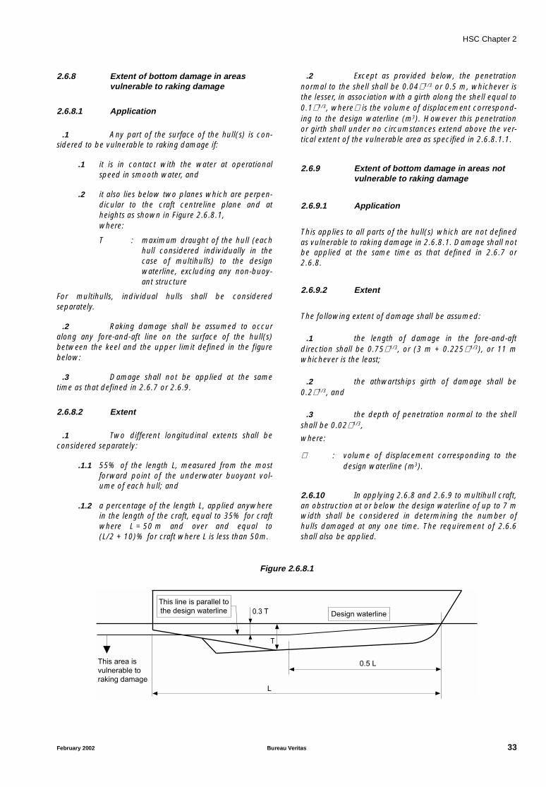
HSC Chapter 2
2.6.8 Extent of bottom damage in areasvulnerable to raking damage
2.6.8.1 Application
.1 Any part of the surface of the hull(s) is con-sidered to be vulnerable to raking damage if:
.1 it is in contact with the water at operationalspeed in smooth water, and
.2 it also lies below two planes which are perpen-dicular to the craft centreline plane and atheights as shown in Figure 2.6.8.1,where:
T : maximum draught of the hull (eachhull considered individually in thecase of multihulls) to the designwaterline, excluding any non-buoy-ant structure
For multihulls, individual hulls shall be consideredseparately.
.2 Raking damage shall be assumed to occuralong any fore-and-aft line on the surface of the hull(s)between the keel and the upper limit defined in the figurebelow:
.3 Damage shall not be applied at the sametime as that defined in 2.6.7 or 2.6.9.
2.6.8.2 Extent
.1 Two different longitudinal extents shall beconsidered separately:
.1.1 55% of the length L, measured from the mostforward point of the underwater buoyant vol-ume of each hull; and
.1.2 a percentage of the length L, applied anywherein the length of the craft, equal to 35% for craftwhere L = 50 m and over and equal to(L/2 + 10)% for craft where L is less than 50m.
.2 Except as provided below, the penetrationnormal to the shell shall be 0.04∇ 1/3 or 0.5 m, whichever isthe lesser, in association with a girth along the shell equal to0.1∇ 1/3, where∇ is the volume of displacement correspond-ing to the design waterline (m3). However this penetrationor girth shall under no circumstances extend above the ver-tical extent of the vulnerable area as specified in 2.6.8.1.1.
2.6.9 Extent of bottom damage in areas notvulnerable to raking damage
2.6.9.1 Application
This applies to all parts of the hull(s) which are not definedas vulnerable to raking damage in 2.6.8.1. Damage shall notbe applied at the same time as that defined in 2.6.7 or2.6.8.
2.6.9.2 Extent
The following extent of damage shall be assumed:
.1 the length of damage in the fore-and-aftdirection shall be 0.75∇ 1/3, or (3 m + 0.225∇ 1/3), or 11 mwhichever is the least;
.2 the athwartships girth of damage shall be0.2∇ 1/3, and
.3 the depth of penetration normal to the shellshall be 0.02∇ 1/3,
where:
∇ : volume of displacement corresponding to thedesign waterline (m3).
2.6.10 In applying 2.6.8 and 2.6.9 to multihull craft,an obstruction at or below the design waterline of up to 7 mwidth shall be considered in determining the number ofhulls damaged at any one time. The requirement of 2.6.6shall also be applied.
Figure 2.6.8.1
This line is parallel to
the design waterline Design waterline
This area is
vulnerable to
raking damage
0.3 T
0.5 L
T
L
February 2002 Bureau Veritas 33

HSC Chapter 2
2.6.11 Following any of the postulated damagesdetailed in 2.6.6 to 2.6.10, the craft in still water shall havesufficient buoyancy and positive stability to simultaneouslyensure that:
.1 for all craft other than amphibious air-cush-ion vehicles, after flooding has ceased and a state ofequilibrium has been reached, the final waterline is belowthe level of any opening through which further floodingcould take place by at least 50% of the significant waveheight corresponding to the worst intended conditions;
.2 for amphibious air-cushion vehicles, afterflooding has ceased and a state of equilibrium has beenreached, the final waterline is below the level of any open-ing through which further flooding could take place by atleast 25% of the significant wave height corresponding tothe worst intended conditions;
.3 there is a positive freeboard from the damagewaterline to survival craft embarkation positions;
.4 essential emergency equipment, emergencyradios, power supplies and public address systems neededfor organizing the evacuation remain accessible andoperational;
.5 the residual stability of craft meets the appro-priate criteria as laid out in annexes 7 and 8 according totable 2.3.4. Within the range of positive stability governedby the criteria of annexes 7 or 8, no unprotected openingshall be submerged.
2.6.12 Downflooding openings referred to in2.6.11.1 and 2.6.11.2 shall include doors and hatcheswhich are used for damage control or evacuation proce-dures, but may exclude those which are closed by means ofweathertight doors and hatch covers and not used for dam-age control or evacuation procedures.
2.7 Inclining and stabilityinformation
2.7.1 Every craft, on completion of build, shall beinclined and the elements of its stability determined. Whenan accurate inclining is not practical, the lightweight dis-placement and centre of gravity shall be determined by alightweight survey and accurate calculation.
2.7.2 The master shall be supplied by the ownerwith reliable information relating to the stability of the craftin accordance with the following provisions of this para-graph. The information relating to stability shall, beforeissued to the master, be submitted to the Administration forapproval, together with a copy thereof for their retention,and shall incorporate such additions and amendments asthe Administration may in any particular case require.
2.7.3 Where any alterations are made to a craft soas significantly to affect the stability information supplied tothe master, amended stability information shall be provided.If necessary the craft shall be re-inclined.
2.7.4 A report of each inclining or lightweight sur-vey carried out in accordance with this chapter and of thecalculation therefrom of the lightweight condition particu-lars shall be submitted to the Administration for approval,together with a copy for their retention. The approvedreport shall be placed on board the craft by the owner inthe custody of the master and shall incorporate such addi-tions and amendments as the Administration may in anyparticular case require. The amended lightweight conditionparticulars so obtained from time to time shall be used bythe master in substitution for such previously approved par-ticulars when calculating the craft's stability.
2.7.5 Following any inclining or lightweight survey,the master shall be supplied with amended stability infor-mation if the Administration so requires. The information sosupplied shall be submitted to the Administration forapproval, together with a copy thereof for their retention,and shall incorporate such additions and amendments asthe Administration may in any particular case require.
2.7.6 Stability information demonstrating compli-ance with this chapter shall be furnished in the form of astability information book which shall be kept on board thecraft at all times in the custody of the master. The informa-tion shall include particulars appropriate to the craft andshall reflect the craft loading conditions and mode of opera-tion. Any enclosed superstructures or deck-houses includedin the cross curves of stability and the critical downfloodingpoints and angles shall be identified. At the operating sta-tion there shall be plans showing clearly for each deck andhold the boundaries of the watertight compartments, theopenings therein with their means of closure and position ofany controls thereof.
2.7.7 Every craft shall have scales of draughtsmarked clearly at the bow and stern. In the case where thedraught marks are not located where they are easily reada-ble, or operational constraints for a particular trade make itdifficult to read the draught marks, then the craft shall alsobe fitted with a reliable draught-indicating system by whichthe bow and stern draughts can be determined.
2.7.8 The owner or builder, as appropriate, shallensure that the positions of the draught marks are accu-rately determined and that the marks are located on the hullin a permanent manner. Accuracy of the draught marksshall be demonstrated to the Administration prior to theinclining experiment.
34 Bureau Veritas February 2002
HSC Chapter 2
2.8 Loading and stability assessment
On completion of loading of the craft and prior to its depar-ture on a voyage, the master shall determine the trim andstability of the craft and also ascertain and record that thecraft is in compliance with stability criteria of the relevantrequirements. The Administration may accept the use of anelectronic loading and stability computer or equivalentmeans for this purpose.
2.9 Marking and recording of thedesign waterline
2.9.1 The design waterline shall be clearly and per-manently marked on the craft's outer sides by the load linemark described below. This and the reference linedescribed in 2.9.2.2 below shall be recorded in the High-Speed Craft Safety Certificate. For craft where this is notpractical, e.g. amphibious air-cushion vehicles fitted withperipheral skirts, defined deck reference points shall be pro-vided, from which the freeboard can be measured, andhence the draughts obtained.
2.9.2 Load line mark
2.9.2.1 The load line mark shall consist of a ring withan outside diameter of 300 mm and width of 25 mm whichis intersected by a horizontal line of length 450 mm andhaving a breadth of 25 mm, the upper edge of which passesthrough the centre of the ring. The centre of the ring shall beplaced at the longitudinal centre of flotation in the displace-
ment mode and at a height corresponding to the designwaterline.
2.9.2.2 To assist in verifying the position of the loadline mark, a reference line shall be marked on the hull at thelongitudinal centre of flotation by a horizontal bar having alength of 300 mm and a breadth of 25 mm and having theupper edge corresponding to the reference line.
2.9.2.3 Where practicable, the reference line shouldbe related to the uppermost deck at side. Where it is notpossible, the position of the reference line should bedefined from the underside of keel at the longitudinal centreof flotation.
2.9.2.4 The mark of the Authority by whom the loadlines are assigned may be indicated alongside the load linering above the horizontal line which passes through thecentre of the ring, or above and below it. This mark shallconsist of not more than four initials to identify the Author-ity's name, each measuring approximately 115 mm inheight, and 75 mm in width.
2.9.2.5 The ring, lines and letters shall be painted inwhite or yellow on a dark ground or in black on a lightground, and permanently marked. The marks shall beplainly visible.
2.9.3 Verification
The High-Speed Craft Safety Certificate shall not be deliv-ered until the Administration has verified that the marks arecorrectly and permanently indicated on the sides of thecraft.
February 2002 Bureau Veritas 35

HSC Chapter 2
Part B Requirements for passenger craft
2.10 General
2.10.1 Where compliance with this chapter requiresconsideration of the effects of passenger weight, the follow-ing information shall be used:
.1 The distribution of passengers is 4 personsper square metre.
.2 Each passenger has a mass of 75 kg.
.3 Vertical centre of gravity of seated passengersis 0.3 m above seat.
.4 Vertical centre of gravity of standing passen-gers is 1.0 m above deck.
.5 Passengers and luggage shall be consideredto be in the space normally at their disposal.
.6 Passengers shall be distributed on availabledeck areas towards one side of the craft on the decks whereassembly stations are located and in such a way that theyproduce the most adverse heeling moment.
2.11 Intact stability in thedisplacement mode
The craft shall have sufficient intact stability that, when instill water conditions, the inclination of the craft from thehorizontal would not exceed 10° (under all permitted casesof loading and uncontrolled passenger movements as mayoccur).
2.12 Intact stability in the non-displacement mode
2.12.1 The total heel angle in still water due to theeffect of passenger movements or due to beam wind pres-sure as per 1.1.4 of annex 6 shall not to exceed 10°.Passenger movement need not be considered where pas-sengers are required to be seated whenever the craft isoperating in the non-displacement mode.
2.12.2 In all loading conditions, the outward heeldue to turning shall not exceed 8°, and the total heel due tobeam wind pressure as per 1.1.4 of annex 6 and due toturning shall not exceed 12°outward.
2.13 Buoyancy and stability in thedisplacement mode followingdamage
2.13.1 Following any of the postulated damagesdetailed in 2.6.6 to 2.6.10, in addition to satisfying therequirements of 2.6.11 and 2.6.12, the craft in still watershall have sufficient buoyancy and positive stability to simul-taneously ensure that:
.1 the angle of inclination of the craft from thehorizontal does not normally exceed 10°in any direction.However, where this is clearly impractical, angles of inclina-tion up to 15° immediately after damage but reducing to10° within 15 min shall be permitted provided that efficientnon-slip deck surfaces and suitable holding points, e.g.,holes, bars, etc., are provided; and
.2 any flooding of passenger compartments orescape routes which might occur will not significantlyimpede the evacuation of passengers.
2.13.2 In addition to the requirements in 2.13.1,category B craft shall also satisfy the following criteria aftersustaining raking damage of 100% of length L, having thegirth and penetration given in 2.6.8.2.2, to any part of thesurface of the hull(s) defined in 2.6.8.1:
.1 The angle of inclination of the craft from thehorizontal shall not exceed 20° in the equilibrium condition;
.2 the range of positive righting lever shall be atleast 15° in the equilibrium condition;
.3 the positive area under the righting levercurve shall be at least 0.015 m-rad in the equilibriumcondition;
.4 the requirements of 2.6.11.3 and 2.13.1.2are satisfied; and
.5 in intermediate stages of flooding, the maxi-mum righting lever shall be at least 0.05 m and the range ofpositive righting lever shall be at least 7°.
In complying with the above, the righting lever curve shallbe terminated at the angle of downflooding, and only onefree surface need be assumed.
2.14 Inclining and stability information
2.14.1 At periodical intervals not exceeding 5 years,a lightweight survey shall be carried out on all passengercraft to verify any changes in lightweight displacement andlongitudinal centre of gravity. The passenger craft shall be
36 Bureau Veritas February 2002

HSC Chapter 2
re-inclined whenever, in comparison with the approved sta-bility information, a deviation from the lightweightdisplacement exceeding 2%, or a deviation of the longitudi-nal centre of gravity exceeding 1% of L is found oranticipated.
2.14.2 A report of each inclining or lightweight sur-vey carried out in accordance with paragraph 2.7.1 and ofthe calculation therefrom of the lightweight condition par-ticulars shall be submitted to the Administration forapproval, together with a copy for their retention. Theapproved report shall be placed on board the craft by theowner in the custody of the master and shall incorporate
such additions and amendments as the Administration mayin any particular case require. The amended lightweightcondition particulars so obtained from time to time shall beused by the master in substitution for such previouslyapproved particulars when calculating the craft's stability.
2.14.3 Following any inclining or lightweight survey,the master shall be supplied with amended stability infor-mation if the Administration so requires. The information sosupplied shall be submitted to the Administration forapproval, together with a copy thereof for their retention,and shall incorporate such additions and amendments asthe Administration may in any particular case require.
February 2002 Bureau Veritas 37

HSC Chapter 2
Part C Requirements for cargo craft
2.15 Buoyancy and stability in thedisplacement mode followingdamage
Following any of the postulated damages detailed in 2.6.6to 2.6.10, in addition to satisfying the requirements of2.6.11 and 2.6.12, the craft in still water shall have sufficientbuoyancy and positive stability to simultaneously ensurethat the angle of inclination of the craft from the horizontaldoes not normally exceed 15° in any direction. However,where this is clearly impractical, angles of inclination up to20° immediately after damage but reducing to 15° within 15minutes may be permitted provided that efficient non-slipdeck surfaces and suitable holding points are provided.
2.16 Inclining
Where it is satisfied by lightweight survey, weighing or otherdemonstration that the lightweight of a craft is closely simi-lar to that of another craft of the series to which 2.7.1 hasbeen applied, the Administration may waive the require-ment of 2.7.1 for craft to be inclined. In this regard, a craftwhich lies within the parameters of 2.14.1, when comparedwith a craft of the series which has been inclined, shall beregarded as being closely similar to that craft.
38 Bureau Veritas February 2002
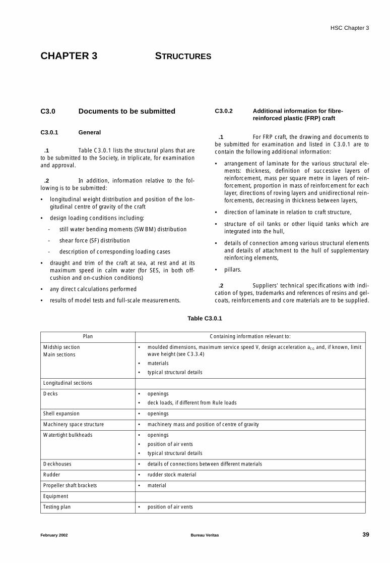
HSC Chapter 3
CHAPTER 3 STRUCTURES
C3.0 Documents to be submitted
C3.0.1 General
.1 Table C3.0.1 lists the structural plans that areto be submitted to the Society, in triplicate, for examinationand approval.
.2 In addition, information relative to the fol-lowing is to be submitted:
• longitudinal weight distribution and position of the lon-gitudinal centre of gravity of the craft
• design loading conditions including:
- still water bending moments (SWBM) distribution
- shear force (SF) distribution
- description of corresponding loading cases
• draught and trim of the craft at sea, at rest and at itsmaximum speed in calm water (for SES, in both off-cushion and on-cushion conditions)
• any direct calculations performed
• results of model tests and full-scale measurements.
C3.0.2 Additional information for fibre-reinforced plastic (FRP) craft
.1 For FRP craft, the drawing and documents tobe submitted for examination and listed in C3.0.1 are tocontain the following additional information:
• arrangement of laminate for the various structural ele-ments: thickness, definition of successive layers ofreinforcement, mass per square metre in layers of rein-forcement, proportion in mass of reinforcement for eachlayer, directions of roving layers and unidirectional rein-forcements, decreasing in thickness between layers,
• direction of laminate in relation to craft structure,
• structure of oil tanks or other liquid tanks which areintegrated into the hull,
• details of connection among various structural elementsand details of attachment to the hull of supplementaryreinforcing elements,
• pillars.
.2 Suppliers’ technical specifications with indi-cation of types, trademarks and references of resins and gel-coats, reinforcements and core materials are to be supplied.
Table C3.0.1
Plan Containing information relevant to:
Midship sectionMain sections
• moulded dimensions, maximum service speed V, design acceleration aCG and, if known, limit wave height (see C3.3.4)
• materials
• typical structural details
Longitudinal sections
Decks • openings
• deck loads, if different from Rule loads
Shell expansion • openings
Machinery space structure • machinery mass and position of centre of gravity
Watertight bulkheads • openings
• position of air vents
• typical structural details
Deckhouses • details of connections between different materials
Rudder • rudder stock material
Propeller shaft brackets • material
Equipment
Testing plan • position of air vents
February 2002 Bureau Veritas 39
HSC Chapter 3
These specifications are to give the following information:
• resins: type (orthophthalic or isophthalic), specific grav-ity, Young’s modulus, Poisson’s ratio, breaking strengthand elongation at break,
• reinforcements (mats, woven rovings, unidirectionalreinforcements): quality (glass or other material, withspecific gravity, breaking strength of the elementaryfibre, Young’s modulus and Poisson’s ratio), mass persquare metre, thickness and possibly weft-warpdistribution,
• core materials: type and quality; specific gravity; tensile,compressive and shear strength and elasticity moduli.
3.1 General
This chapter covers those elements of hull and superstruc-ture which provide longitudinal and other primary and localstrength of the craft as a whole and also other importantcomponents such as foils and skirts which are directly asso-ciated with the hull and superstructure.
3.2 Materials
Materials used for the hull and superstructure and the otherfeatures referred to in 3.1 should be adequate for theintended use of the craft.
3.3 Structural strength
The structure should be capable of withstanding the staticand dynamic loads which can act on the craft under alloperating conditions in which the craft is permitted to oper-ate, without such loading resulting in inadmissibledeformation and loss of watertightness or interfering withthe safe operation of the craft.
3.4 Cyclic loads
Cyclic loads, including those from vibrations (see note),which can occur on the craft should not:
• impair the integrity of structure during the anticipatedservice life of the craft or the service life agreed with theAdministration;
• hinder normal functioning of machinery and equip-ment; and
• impair the ability of the crew to carry out its duties.
Note: In scope of classification, the structural strength againstvibrations is not checked.
The vibration check shall be performed during the sea trials of thecraft. Where deemed necessary, the Society may require vibration
measurements to be carried out using suitable instruments; whereappropriate, remedial measures may be required to adequatelyeliminate situations deemed unacceptable.
3.5 Design criteria
The Administration should be satisfied that the choice ofdesign conditions, design loads and accepted safety factorscorresponds to the intended operating conditions for whichcertification is sought.
3.6 Trials
If the Administration consider it necessary it should requirefull-scale trials to be undertaken in which loadings are deter-mined. Cognizance should be taken of the results wherethese indicate that loading assumptions of structural calcu-lations have been inadequate.
C3.1 General
C3.1.1 Introductory comments
.1 This Chapter C3 contains the requirementsfor structural scantlings of the craft to which these Rulesapply, i.e. to craft for which V ≥ 7,16 ∆1/6. Craft for whichV ≥ 10 L0,5 shall be individually considered by the Society(V in knots, ∆ in tonnes).
For what concerns multihull craft, this Chapter provides therequirements for scantlings of twin-hull craft. Other craftwill be considered in each separate case by the Society.
.2 The requirements for scantlings of hydrofoilsand air-cushion vehicles are contained in Appendices C3A1and C3A2. Unless otherwise specified, the requirements ofthis Chapter apply to such craft only as far as the provisionsregarding limit operating conditions, materials and con-struction criteria are concerned.
.3 The scantlings indicated in the following par-agraphs apply to craft constructed of steel, aluminium alloyor fibre reinforced plastic, as specified in C3.2.
C3.1.2 Direct calculations
.1 The Society may require direct calculationsto be carried out, if deemed necessary according to the pro-visions of C3.6.
Such calculations are to be carried out based on structuralmodelling, loading and checking criteria described in C3.6.Calculations based on other criteria may be accepted ifdeemed equivalent to those laid down by the Society.
40 Bureau Veritas February 2002
HSC Chapter 3
C3.1.3 Units
.1 Unless otherwise specified, the followingunits are used in the Rules:
• thickness of plating, in mm,
• section modulus of stiffeners, in cm3,
• shear area of stiffeners, in cm2,
• span and spacing of stiffeners, in m,
• stresses, in N/mm2,
• concentrated loads, in kN,
• distributed loads, in kN/m or kN/m2.
C3.1.4 Definitions and symbols
.1 The definitions of the following terms andsymbols are applicable throughout this Chapter and itsAppendices and are not, as a rule, repeated in the differentparagraphs. Definitions applicable only to certain para-graphs are specified therein.
- “Moulded base line”: The line parallel to the summerload waterline, crossing the upper side of keel plate orthe top of skeg at the middle of length L.
- “Hull”: The hull is the outer boundary of the enclosedspaces of the craft, except for the deckhouses, asdefined below.
- “Chine”: For hulls that do not have a clearly identifiedchine, the chine is the hull point at which the tangent tothe hull is inclined 50° to the horizontal.
- “Bottom”: The bottom is the part of the hull between thekeel and the chines.
- “Main deck”: The main deck is the uppermost completedeck of the hull. It may be stepped.
- “Side”: The side is the part of the hull between the chineand the main deck.
- “Deckhouse”: The deckhouse is a decked structurelocated above the main deck, with lateral walls inboardof the side of more than 4 per cent of the local breadth.Structure located on the main deck and whose walls arenot in the same longitudinal plane as the under sideshell may be regarded as a deckhouse.
- “Cross-deck”: For twin-hull craft, the cross-deck is thestructure connecting the two hulls.
- “Deadrise angle αd”: For hulls that do not have a clearlyidentified deadrise angle, αd is the angle between thehorizontal and a straight line joining the keel and thechine. For catamarans with non-symmetrical hulls(where inner and outer deadrise angles are different),αd
is the lesser angle.
- “Fore end”: Hull region forward of 0,9 L from the aftperpendicular.
- “Aft end”: Hull region abaft of 0,1 L from the aftperpendicular.
- “Midship area”: Hull region between 0,3 L and 0,7 Lfrom the aft perpendicular.
L : Rule length, in m, equal to LWL where LWL is thewaterline measured with the craft at rest incalm water and, for SESs, in the off-cushioncondition
FP : forward perpendicular, i.e. the perpendicular atthe intersection of the waterline at draught Tand the foreside of the stem
AP : aft perpendicular, i.e. the perpendicular locatedat a distance L abaft of the forward perpendicu-lar
B : the greatest moulded breadth, in m, of the craft
Bw : the greatest moulded breadth, in m, measuredon the waterline at draught T; for catamarans,Bw is the breadth of each hull
Bwm : the greatest moulded breadth, in m, measuredbelow or on the waterline at draught T; for cat-amarans, Bwm is the breadth of each hull
D : depth, in m, measured vertically in the trans-verse section at the middle of length L from themoulded base line of the hull(s) to the top ofthe deck beam at one side of the main deck (ifthe main deck is stepped, D will be defined ineach separate case at the discretion of theSociety)
T : draught of the craft, in m, measured verticallyon the transverse section at the middle oflength L, from the moulded base line of thehull(s) to the full load waterline, with the craftat rest in calm water and, for SESs, in the off-cushion condition
∆ : moulded displacement at draught T, in seawater (mass density = 1,025 t/m3), in tonnes
CB : total block coefficient, defined as follows:
For catamarans, CB is to be calculated for a sin-gle hull, assuming ∆ equal to one half of thecraft’s displacement
V : maximum service speed, in knots
g : acceleration of gravity, equal to 9,81 m/s2
LCG : longitudinal centre of gravity of the craft.
C3.1.5 Protection against corrosion
.1 Scantlings stipulated in C3.7 assume that thematerials used are chosen and protected in such a way thatthe strength lost by corrosion is negligible.
.2 The Shipyard is to give the Society a docu-ment specifying all the arrangements made to protect thematerial against corrosion at the construction stage: coatingtypes, number and thickness of layers, surface preparation,application conditions, control after completion, anodicprotection, etc.
CB∆
1 025 L BW T⋅ ⋅ ⋅,( )------------------------------------------------=
February 2002 Bureau Veritas 41
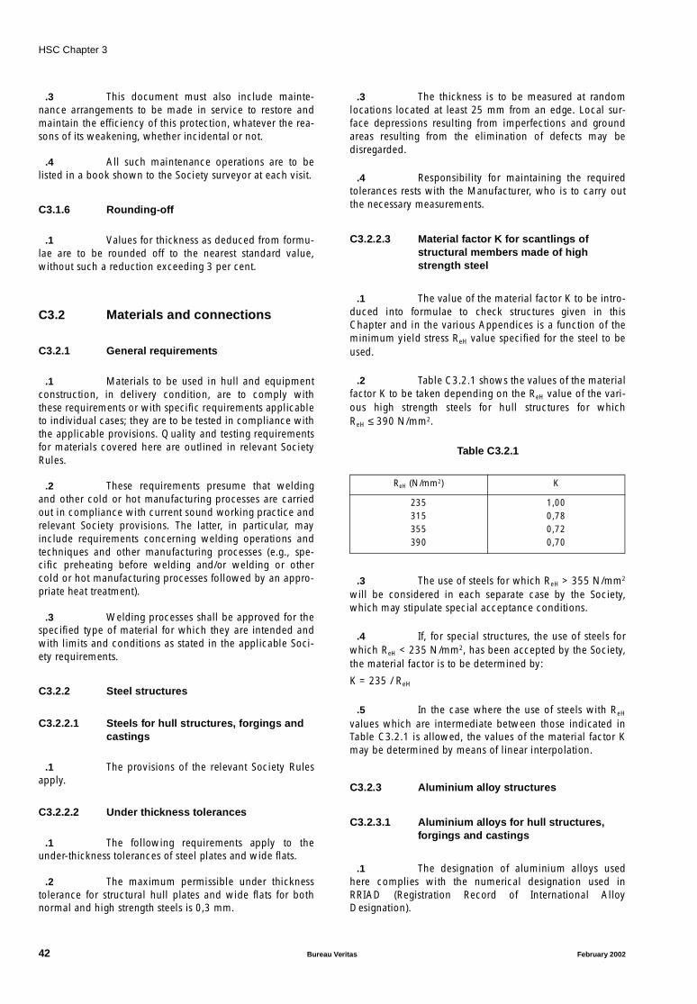
HSC Chapter 3
.3 This document must also include mainte-nance arrangements to be made in service to restore andmaintain the efficiency of this protection, whatever the rea-sons of its weakening, whether incidental or not.
.4 All such maintenance operations are to belisted in a book shown to the Society surveyor at each visit.
C3.1.6 Rounding-off
.1 Values for thickness as deduced from formu-lae are to be rounded off to the nearest standard value,without such a reduction exceeding 3 per cent.
C3.2 Materials and connections
C3.2.1 General requirements
.1 Materials to be used in hull and equipmentconstruction, in delivery condition, are to comply withthese requirements or with specific requirements applicableto individual cases; they are to be tested in compliance withthe applicable provisions. Quality and testing requirementsfor materials covered here are outlined in relevant SocietyRules.
.2 These requirements presume that weldingand other cold or hot manufacturing processes are carriedout in compliance with current sound working practice andrelevant Society provisions. The latter, in particular, mayinclude requirements concerning welding operations andtechniques and other manufacturing processes (e.g., spe-cific preheating before welding and/or welding or othercold or hot manufacturing processes followed by an appro-priate heat treatment).
.3 Welding processes shall be approved for thespecified type of material for which they are intended andwith limits and conditions as stated in the applicable Soci-ety requirements.
C3.2.2 Steel structures
C3.2.2.1 Steels for hull structures, forgings andcastings
.1 The provisions of the relevant Society Rulesapply.
C3.2.2.2 Under thickness tolerances
.1 The following requirements apply to theunder-thickness tolerances of steel plates and wide flats.
.2 The maximum permissible under thicknesstolerance for structural hull plates and wide flats for bothnormal and high strength steels is 0,3 mm.
.3 The thickness is to be measured at randomlocations located at least 25 mm from an edge. Local sur-face depressions resulting from imperfections and groundareas resulting from the elimination of defects may bedisregarded.
.4 Responsibility for maintaining the requiredtolerances rests with the Manufacturer, who is to carry outthe necessary measurements.
C3.2.2.3 Material factor K for scantlings ofstructural members made of highstrength steel
.1 The value of the material factor K to be intro-duced into formulae to check structures given in thisChapter and in the various Appendices is a function of theminimum yield stress ReH value specified for the steel to beused.
.2 Table C3.2.1 shows the values of the materialfactor K to be taken depending on the ReH value of the vari-ous high strength steels for hull structures for whichReH ≤ 390 N/mm2.
Table C3.2.1
.3 The use of steels for which ReH > 355 N/mm2
will be considered in each separate case by the Society,which may stipulate special acceptance conditions.
.4 If, for special structures, the use of steels forwhich ReH < 235 N/mm2, has been accepted by the Society,the material factor is to be determined by:
K = 235 / ReH
.5 In the case where the use of steels with ReH
values which are intermediate between those indicated inTable C3.2.1 is allowed, the values of the material factor Kmay be determined by means of linear interpolation.
C3.2.3 Aluminium alloy structures
C3.2.3.1 Aluminium alloys for hull structures,forgings and castings
.1 The designation of aluminium alloys usedhere complies with the numerical designation used inRRIAD (Registration Record of International AlloyDesignation).
ReH (N/mm2) K
235315355390
1,000,780,720,70
42 Bureau Veritas February 2002
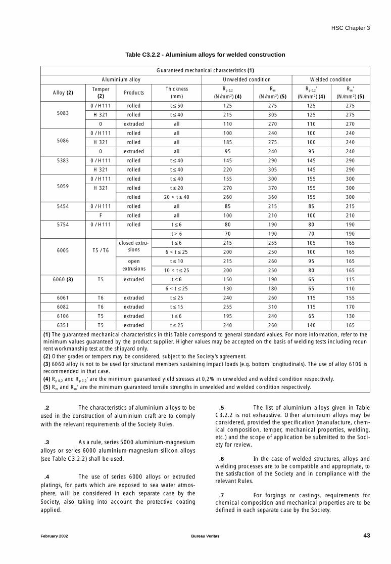
HSC Chapter 3
Table C3.2.2 - Aluminium alloys for welded construction
.2 The characteristics of aluminium alloys to beused in the construction of aluminium craft are to complywith the relevant requirements of the Society Rules.
.3 As a rule, series 5000 aluminium-magnesiumalloys or series 6000 aluminium-magnesium-silicon alloys(see Table C3.2.2) shall be used.
.4 The use of series 6000 alloys or extrudedplatings, for parts which are exposed to sea water atmos-phere, will be considered in each separate case by theSociety, also taking into account the protective coatingapplied.
.5 The list of aluminium alloys given in TableC3.2.2 is not exhaustive. Other aluminium alloys may beconsidered, provided the specification (manufacture, chem-ical composition, temper, mechanical properties, welding,etc.) and the scope of application be submitted to the Soci-ety for review.
.6 In the case of welded structures, alloys andwelding processes are to be compatible and appropriate, tothe satisfaction of the Society and in compliance with therelevant Rules.
.7 For forgings or castings, requirements forchemical composition and mechanical properties are to bedefined in each separate case by the Society.
Guaranteed mechanical characteristics (1)
Aluminium alloy Unwelded condition Welded condition
Alloy (2)Temper
(2)Products
Thickness(mm)
Rp 0,2
(N/mm2) (4)Rm
(N/mm2) (5)Rp 0,2’
(N/mm2) (4)Rm’
(N/mm2) (5)
50830 / H111 rolled t ≤ 50 125 275 125 275
H 321 rolled t ≤ 40 215 305 125 275
0 extruded all 110 270 110 270
50860 / H111 rolled all 100 240 100 240
H 321 rolled all 185 275 100 240
0 extruded all 95 240 95 240
5383 0 / H111 rolled t ≤ 40 145 290 145 290
H 321 rolled t ≤ 40 220 305 145 290
50590 / H111 rolled t ≤ 40 155 300 155 300
H 321 rolled t ≤ 20 270 370 155 300
rolled 20 < t ≤ 40 260 360 155 300
5454 0 / H111 rolled all 85 215 85 215
F rolled all 100 210 100 210
5754 0 / H111 rolled t ≤ 6 80 190 80 190
t > 6 70 190 70 190
6005 T5 / T6closed extru-
sionst ≤ 6 215 255 105 165
6 < t ≤ 25 200 250 100 165
openextrusions
t ≤ 10 215 260 95 165
10 < t ≤ 25 200 250 80 165
6060 (3) T5 extruded t ≤ 6 150 190 65 115
6 < t ≤ 25 130 180 65 110
6061 T6 extruded t ≤ 25 240 260 115 155
6082 T6 extruded t ≤ 15 255 310 115 170
6106 T5 extruded t ≤ 6 195 240 65 130
6351 T5 extruded t ≤ 25 240 260 140 165
(1) The guaranteed mechanical characteristics in this Table correspond to general standard values. For more information, refer to theminimum values guaranteed by the product supplier. Higher values may be accepted on the basis of welding tests including recur-rent workmanship test at the shipyard only.(2) Other grades or tempers may be considered, subject to the Society’s agreement.(3) 6060 alloy is not to be used for structural members sustaining impact loads (e.g. bottom longitudinals). The use of alloy 6106 isrecommended in that case.(4) Rp 0,2 and Rp 0,2’ are the minimum guaranteed yield stresses at 0,2% in unwelded and welded condition respectively.(5) Rm and Rm’ are the minimum guaranteed tensile strengths in unwelded and welded condition respectively.
February 2002 Bureau Veritas 43

HSC Chapter 3
.8 In the case of structures subjected to lowservice temperatures or intended for other particular appli-cations, the alloys to be employed are to be defined in eachseparate case by the Society which is to state the acceptabil-ity requirements and conditions.
.9 Unless otherwise specified, the Young’s mod-ulus for aluminium alloys is equal to 70000 N/mm2 and thePoisson’s ratio equal to 0,33.
C3.2.3.2 Extruded platings
.1 Extrusions with built-in plating and stiffeners,referred to as extruded plating, may be used.
.2 In general, the application is limited to decksand deckhouses. Other uses may be permitted at the discre-tion of the Society.
.3 Extruded plating is preferably to be orientedso that the stiffeners be parallel to the direction of mainstresses.
.4 Connections between extruded plating andprimary members are to be given special attention.
C3.2.3.3 Tolerances
.1 The under-thickness tolerances of plates androlled sections are to be in accordance with Table C3.2.3.
Table C3.2.3
.2 The under-thickness tolerances of extrudedplatings are to be in accordance with Table C3.2.4, but nottaken greater than 7% of the as-built thickness. Otherwise,the reduced plate thickness has to be considered.
Table C3.2.4
.3 The responsibility for maintaining therequired tolerances lies with the manufacturer, who shallalso inspect the surface condition.
C3.2.3.4 Influence of welding on mechanicalcharacteristics
.1 Welding heat input lowers locally themechanical strength of aluminium alloys hardened by workhardening (series 5000 other than condition 0 or H111) orby heat treatment (series 6000).
.2 Consequently, where necessary, a drop inmechanical characteristics of welded structures is to beconsidered in the heat-affected zone, with respect to themechanical characteristics of the parent material.
.3 The heat-affected zone may be taken toextend 25 mm on each side of the weld axis.
.4 Aluminium alloys of series 5000 in 0 condi-tion (annealed) or in H111 condition (annealed flattened)are not subject to a drop in mechanical strength in thewelded areas.
.5 Aluminium alloys of series 5000 other thancondition 0 or H111 are subjected to a drop in mechanicalstrength in the welded areas. The mechanical characteristicsto consider in welded condition are, normally, those of con-dition 0 or H111, except otherwise indicated in TableC3.2.2. Higher mechanical characteristics may be takeninto account, provided they are duly justified.
.6 Aluminium alloys of series 6000 are subjectto a drop in mechanical strength in the vicinity of thewelded areas. The mechanical characteristics to be consid-ered in welded condition are, normally, to be indicated bythe supplier, if not indicated in Table C3.2.2.
C3.2.3.5 Material factor K for scantlings ofstructural members made of aluminiumalloy
.1 The value of the material factor K to be intro-duced into formulae for checking scantlings of structuralmembers, given in this Chapter and the various Appendices,is determined by the following equation:
where:
R’lim : minimum guaranteed yield stress of the parentmetal in welded condition R’p0,2, in N/mm2, butnot to be taken greater than 70% of the mini-mum guaranteed tensile strength of the parentmetal in welded condition R’m, in N/mm2 (seeTable C3.2.2).
.2 For welded constructions in hardened alu-minium alloys (series 5000 other than condition 0 or H111and series 6000), greater characteristics than those inwelded condition may be considered, provided that weldedconnections are located in areas where stress levels areacceptable for the alloy considered in annealed or weldedcondition.
As-built thickness(mm)
Under-thickness tolerance (mm)
t ≤ 8 0,3
8 < t ≤ 12 0,5
12 < t ≤ 20 0,7
t > 20 1,0
As-built thickness(mm)
Under-thickness tolerance (mm)
t ≤ 6 0,3
6 < t ≤ 10 0,4
K 100R ′ lim
-----------=
44 Bureau Veritas February 2002
HSC Chapter 3
.3 In case of welding of two different alumin-ium alloys, the material factor K to be considered for thescantlings of welds is to be the greater material factor of thealuminium alloys of the assembly.
C3.2.3.6 Strength of welding
.1 The effective length in mm of the lines ofwelding is given by:de = d − 20
where d is the actual length in mm of the line of welding.
C3.2.3.7 Riveted connections for aluminium alloyhulls
.1 Use of rivets for connecting structures is lim-ited, in principle, only to members which do not contributeto the overall strength of the hull. Exceptions are to be sup-ported by experimental evidence or good in-serviceperformance.
.2 The conditions for riveted connectionacceptability are to be individually stated in each particularcase, depending on the type of member to be connectedand the rivet material.
.3 Whenever riveted connections are to beemployed, a detailed plan, illustrating the process, as wellas the dimensions and location of rivets and holes, togetherwith the mechanical and metallurgical properties of the riv-ets, is to be submitted for approval.
.4 The Society may, at its discretion, requiretension, compression and shear tests to be carried out onspecimens of riveted connections constructed under thesame conditions as during actual hull construction, to bewitnessed by a Society surveyor.
.5 The Society reserves the right to accept theresults of tests performed by recognized bodies or otherSocieties.
C3.2.4 Welding connections
C3.2.4.1 General requirements
.1 For welding, the requirements of relevantSociety Rules apply. In particular, these provisions make theadoption of welding procedures dependent on their previ-ous qualification by the Society. In addition, individualbuilders are to hold an authorization by the Society to usethese procedures, employing welders qualified by theSociety.
.2 For welds design and throat thicknesses, therequirements of relevant Society Rules apply.In addition, intermittent welds are not allowed in followingzones:
- structure in way of waterjets or propellers
- structure in way of stabilisation devices such as foils,interceptors or tabs
- structure submitted to water impact
C3.2.4.2 Accessibility and edge preparation
.1 For correct execution of welded joints, suffi-cient accessibility is necessary, depending on the weldingprocess adopted and the welding position.
.2 Edge cutting, to be carried out in general bymachining, is to be regular and without burrs or cuts.
.3 The structural parts to be welded as well asthose adjacent, even if they have been previously pickled,are to be cleaned carefully before welding, using suitablemechanical means, such as stainless steel wire brushes, soas to eliminate oxides, grease or other foreign bodies whichcould give rise to welding defects.
.4 Edge preparation, alignment of joints, spot-welding methods and root chipping are to be appropriate tothe type of joint and welding position, and comply withSociety Rule requirements for the welding proceduresadopted.
C3.2.4.3 Inspections
.1 Inspections of welded connections by theSociety surveyors are, in general, those specified in (a) to (e)below. The extent of inspection will be defined by the Soci-ety on a case by case basis.
(a) Inspection of base materials for compliance with therequirements this Article and of structures with theapproved plans.
(b) Inspection of the use and application conditions ofwelding procedures for compliance with thoseapproved and verification that qualified welders areemployed.
(c) Visual examination of edge preparations, root chippingand execution of welds in way of structuralconnections.
(d) Examination of radiographs of welded joints (radio-graphing is to be performed, if necessary, depending onthe extent of the examinations), and inspection of per-formance of execution of the ultrasonic or magneticparticle examinations, which may be required.
(e) Inspection of any repairs, to be performed with proce-dures and inspection methods at the discretion of theSociety surveyor.
.2 Irrespective of the extent of such inspections,it is the responsibility of the builder to ensure that the man-ufacturing procedures, processes and sequences are incompliance with relevant Society requirements, approvedplans and sound working practice. For this purpose, theshipyard is to have its own production control organization.
February 2002 Bureau Veritas 45
HSC Chapter 3
C3.2.4.4 Welding processes for light alloys
.1 In general, the welding of the hull structuresis to be performed with the MIG (metal-arc inert gas) andTIG (tungsten-arc inert gas) processes using welding con-sumables recognized as suitable for the base material to beused. Welding processes and filler materials other thanthose above are to be individually considered by the Soci-ety at the time of the approval of welding procedures.
.2 For the authorization to use welding proce-dures in production, the following details are to be stated:
(a) grade and temper of parent and filler materials
(b) weld execution procedures: type of joint (e.g. butt-joint,fillet joint); edge preparation (e.g. thicknesses, bevelling,right angle edges); welding position (e.g. flat, vertical,horizontal) and other parameters (e.g. voltage, amper-age, gas flow capacity)
(c) welding conditions (e.g. cleaning procedures of edgesto be welded, protection from environmentalatmosphere)
(d) special operating requirements for butt-joints, for exam-ple for plating: welding to be started and completed onend pieces outside the joint, back chipping, arrange-ments for repairs consequent to possible arc restarts
(e) type and extent of controls during production.
C3.2.5 Corrosion protection - heterogeneoussteel/aluminium alloy assembly
.1 Connections between aluminium alloy parts,and between aluminium alloy and steel parts, if any, are tobe protected against corrosion by means of coatings appliedby suitable procedures agreed by the Society.
.2 In any case, any direct contact between steeland aluminium alloy is to be avoided (e.g. by means of zincor cadmium plating of the steel parts and application of asuitable coating on the corresponding light alloy parts).
.3 Any heterogeneous jointing system is subjectto the Society’s agreement.
.4 The use of transition joints made of alumin-ium/steel-cladded plates or profiles is subject to theSociety’s agreement.
.5 Transition joints are to be type-approved.
.6 Qualifications tests for welding proceduresare to be carried out for each joint configuration.
.7 A welding booklet giving preparations andvarious welding parameters for each type of assembly is tobe submitted for review.
C3.2.6 Fibre-reinforced plastic (FRP) structures
C3.2.6.1 Raw materials
.1 The main raw materials are to be homolo-gated by the Society.
It may be accepted as equivalent that main raw materialsshould be individually inspected by the Society. In such acase, each batch being used is submitted to tests, the condi-tions and scope of which are stipulated by the Society’ssurveyor.
.2 Reinforcement fibres
(a) Fibres for reinforcement may be textile glass or aramidor carbon fibres or other fibres.
(b) Products laid on a surface, such as size, binder and cou-pling finish, are to ensure cohesion between fibres andresins.
(c) During manufacturing, the shipyard is to ensure thatreinforcement materials are to be free from scrap matterand without defects, detrimental to their use.
.3 Resins
(a) Resins are to be capable of withstanding ageing inmarine environments and industrial atmospheres.
(b) Resins are to be used within the limits fixed by the man-ufacturer. In this respect, the surveyor may ask for anyrelevant proof.
.4 Core materials for sandwich laminates
(a) Expanded foams contributing to sandwich laminatestrength are to be of the closed cell type and compatiblewith the resins used.
(b) Expanded polystyrenes may be used only as filling orbuoyancy materials.
.5 Additives
(a) Fillers and pigments are to affect neither the conditionsof polymerisation of the impregnation resin nor itsmechanical characteristics. The percentage of both ofthem is not to exceed, as a rule, 10% of the mass ofresin, with a maximum of 2% for thixotropic agents and5% for flame retarders.
The use of microspheres is subject to specialexamination.
(b) The type and proportions of catalyst and accelerator areto be adjusted in any case to the conditions of work(production rate) and ambient atmosphere (tempera-ture).
In order to ensure complete curing, the builder is torespect the indications of the resin manufacturer, partic-ularly for the ratio of catalyst.
46 Bureau Veritas February 2002
HSC Chapter 3
.6 Materials for integrated structures
(a) These are elements entirely covered with laminate, andused for reinforcement, moulding, or as lamination sup-port for stiffeners, for example.
(b) The metals used are withstand seawater and fuel corro-sion; they are to be of good quality and must not haveany influence on resin curing.They are to undergo appropriate preparation to improvebonding with the resin.
(c) As a rule, wood reinforcements are to be of a plywoodtype with good seawater resistance. The use of timber issubject to a special examination.
C3.2.6.2 Tests on laminates
.1 General
(a) The shipyard has to make samples representative ofshell materials and possibly of other parts of the struc-ture, taking into account the type and size of ship.
(b) If sister ships are built at the same shipyard, and pro-vided that raw materials are not changed, the frequencyof samples for testing is determined by the Society.
(c) These test samples are to be submitted to a laboratoryapproved by the Society to undergo mechanical andphysicochemical tests, as defined below.
(d) In general, tests are to be carried out according to thestandards indicated below, or other recognized stand-ards previously agreed upon with the Society.
(e) These tests must show that laminate characteristics areat least equivalent to the theoretical values given bydirect calculation following the method given inC3.2.6.3. Otherwise, supplementary tests may berequired.
(f) The Society reserves the right to require tests differentfrom those defined below, if particular materials or unu-sual manufacturing process are used.
(g) Tests are to be carried out on a panel, the compositionof which is to be the same as that of a shell plating area,without gel-coat.
(h) Identification of the panel is given by the followingelements:
- exact name of the resin, with its specific gravity,elasticity modulus, and breaking stress in curingstate,
- description of elementary layers,
- characteristics of the laminate (e.g. layer type,direction),
- direction of the panel in respect of longitudinal axisof the ship and indication of direction for warp andweft for the rovings in respect of the same axis.
(i) Conditioning of laminate panels, preparation of test-pieces, dimensional measurement of testpieces and thetests defined below are to be carried out according torecognized standards.
(j) Tests are to be carried out on testpieces taken out of thepanel in two perpendicular directions. The number oftestpieces for each direction is given by the standardused for the particular test.
(k) For each group of testpieces and for each result, thevalue to consider is the average obtained from thenumber of tested pieces, provided that the minimumvalue is not less than 0,9 times the mean value. Other-wise, the value to consider is determined by the Society,taking testing conditions and dispersion of results intoaccount.
(l) Mechanical characteristics are to be obtained from drytestpieces, i.e. not conditioned in water.
(m) In general, the following tests are to be carried out:
- single skin laminates: tensile tests, bending tests(three-point method), measurement of specific grav-ity and percentage of reinforcement in mass,
- sandwich laminates: bending tests (four-pointmethod), and, for each skin, tensile tests, measure-ment of specific gravity and percentage ofreinforcement in mass.
(n) Bending tests are to be carried out with the load appliedeither on the gel-coat side or on the opposite side. Thechoice of the side is to be decided in accordance withthe Society, so that the failure mode of the testpiece isrepresentative of the case of scantlings of the plating.
(o) Test results are to be shown in a test report, mentioningthe tests in C3.2.6.22 to C3.2.6.24.
.2 Tensile tests
(a) In general, these tests are to be carried out for singleskin laminates and the skins of sandwich laminates.
(b) The applicable standard is:ISO 3268.
(c) For each testpiece, the test report is to provide the fol-lowing information:
- reference of the standard used for the test,
- widths and thicknesses of the test-piece, in mm,
- length between fixed ends, in mm,
- load (in N) - elongation curve (in mm),
- breaking load, in N,
- tensile breaking stress, in N/mm2,
- tangential initial elasticity modulus, in N/mm2,
- other items of information required by the standard,if necessary.
(d) If breaking occurs in several steps, the value taken intoaccount is the first break obtained from the load-elonga-tion curve.
(e) The test report is also to indicate the mean value of thebreaking load, breaking tensile strength and tangentialinitial elasticity modulus.
February 2002 Bureau Veritas 47
HSC Chapter 3
.3 Bending tests
(a) In general, bending tests using the three-point methodare to be carried out only for the single skin laminates.
The applicable standard is:
ISO 178.
(b) In general, bending tests using the four-point methodare to be carried out only for sandwich laminates.
The applicable standard is:
ASTM C 393.
(c) For each testpiece, the test report is to provide the fol-lowing information:
- reference of the standard used for the test,
- widths and thicknesses of the testpiece, in mm,
- length of the span between supports, in mm,
- for the four-point method: location of the pointswhere the load is applied,
- load (in N) - deflection (in mm) curve,
- breaking load, in N, and failure mode,
- bending breaking strength, in N/mm2, for single skinlaminate tests,
- bending breaking strength of skin and shear break-ing strength of core for sandwich laminate tests,both in N/mm2,
- other items of information required by the standard,if necessary.
(d) If breaking occurs in several steps, the value taken intoaccount is the first break obtained from the load-deflec-tion curve.
(e) The test report is also to indicate the mean value of thebreaking load and breaking strength.
.4 Specific gravity and percentage ofreinforcement
(a) In general, these tests are to be carried out for singleskin laminates and the skins of sandwich laminates.
(b) The applicable standards are:
ASTM D 792,
ASTM D 3171.
(c) For each testpiece, the test report is to provide the fol-lowing information:
- reference of the standard used for the test,
- dimensions, in mm, of the test-piece,
- mass of the test-piece, in g,
- mass by unit of area of the test-piece, in g/m2,
- specific density, in g/m3,
- mass of reinforcement of the test-piece, in g,
- mass of reinforcement by unit of area, in g/m2,
- percentage of reinforcement in mass,
- other items of information required by the standard,if necessary.
(d) The test report is also to indicate the mean value of themass by unit of area, in g/m2, specific gravity, in g/m3,mass of reinforcement by unit of area, in g/m2, and per-centage of reinforcement in mass.
C3.2.6.3 Estimation of mechanical characteristicsof FRP materials
.1 The meanings of the symbols used below areas follows:
Ψ : content in mass of reinforcement in a layer,
ϕ : content in volume of reinforcement in a layer,defined in C3.2.6.32 below,
µ0 : vacuum content, equal to 0, if there is no avail-able information,
E1 : Young’s modulus of a layer with unidirectionalfibres, parallel to fibres, in N/mm2, defined inC3.2.6.32 below,
E2 : Young’s modulus of a layer with unidirectionalfibres, perpendicular to fibres, in N/mm2,defined in C3.2.6.32 below,
ν12,ν21 : Poisson’s ratios of a layer with unidirectionalfibres, defined in C3.2.6.32 below,
G12 : Coulomb’s modulus of a layer with unidirec-tional fibres, in N/mm2, defined in C3.2.6.32below,
ρv : specific gravity of reinforcement, in g/cm3,
ρr : specific gravity of resin, in g/cm3,
E1v : Young’s modulus of reinforcement in the direc-tion parallel to fibres, in N/mm2,
E2v : Young’s modulus of reinforcement in the direc-tion perpendicular to fibres, in N/mm2,
Er : Young’s modulus of resin, in N/mm2,
νv : Poisson’s ratio of reinforcement,
νr : Poisson’s ratio of resin,
Gr : Coulomb’s modulus of resin, in N/mm2, definedin C3.2.6.32 below,
Gv : Coulomb’s modulus of the reinforcement, inN/mm2, as given in Table C3.2.7.
When there is no available information, the values given inTable C3.2.7 may be considered.
48 Bureau Veritas February 2002

HSC Chapter 3
Table C3.2.7
.2 Elementary layer
(a) The content in volume ϕ of reinforcement in the layer isgiven by the formula:
(b) Whatever the type of reinforcement used in a particularlayer, the elastic characteristics of a layer with unidirec-tional fibres having the same content of reinforcementas that layer are to be calculated first:
• Young’s moduli:
- parallel to fibres
- perpendicular to fibres
• Poisson’s ratios:
• Coulomb’s modulus:
where:
(c) Following any direction that forms an angle θ with thedirection of fibres, the Young’s moduli of the elemen-tary layer become:
The values of E1, E2, ν12 and G12 are calculated above,directions x and y are defined in Figure C3.2.1.
Figure C3.2.1
(d) In general, the content in mass of reinforcement in alayer of mat is between 0,25 and 0,35.
The Young’s modulus of a layer of mat may be esti-mated from:
In this formula, the values E1 and E2 are those definedabove.
(e) Woven rovings may be taffeta, cotton serge, satin, etc.,warp and weft balanced or not.
In general, the content in mass of reinforcement in awoven roving reinforced layer is between 0,4 and 0,6,and the content in mass of reinforcement in an unidirec-tional reinforced layer is between 0,6 and 0,7.
The direction of the warp (direction 1) is to be distin-guished from that of the weft (direction 2); the elasticcharacteristics are:
where k is the woven balance coefficient equal to theratio of warp tensile strength to the sum of tensilestrengths in warp and weft, E1 and E2 being definedabove.
Generally, a layer reinforced with woven rovings maybe considered as made of two perpendicular unidirec-tional layers, and it is possible to apply directly to themthe formulae laid down above, taking into account theactual content of reinforcement in the layer.
Fibres Resins
E Glass Aramid HS Carbon HM Carbon Polyester Epoxy
Specific gravity (g/cm3) 2,54 1,45 1,80 1,90 1,20 1,20
Young’s modu-lus (N/mm2)
parallel to fibres 73000 130000 230000 370000 3000 2600
perpendicular to fibres 73000 5400 15000 6000 − −
Coulomb’s modulus (N/mm2) 30000 12000 50000 20000 − −
Poisson’s ratio 0,25 0,35 0,35 0,35 0,316 0,40
ϕ ψ 1 µ0–( )⋅
ψ 1 ψ–( )ρv
ρr
-----⋅+
--------------------------------------=
E1 ϕ E1v⋅ 1 ϕ–( ) Er⋅+=
E2Er
1 ν r2–
-------------- 1 0 85, ϕ 2⋅+
1 ϕ–( )1 25, ϕEr
E2v 1 ν r2–( )
---------------------------+
---------------------------------------------------------------⋅=
ν12 ϕ ν v⋅ 1 ϕ–( ) ν r⋅+=
ν21 ν12E2
E1
-----⋅=
G12 Gr1 0 6, ϕ0 5,⋅+
1 ϕ–( )1 25, Gr
Gv
------ ϕ⋅+-----------------------------------------------⋅=
GrEr
2 1 ν r+( )⋅--------------------------=
1Ex
----1E1
----- θcos4 1G12
--------2ν12
E1
-----------– ⋅+⋅=
θsin2 θcos2 1E2
----- θsin4⋅+⋅ ⋅
1Ey
----1E1
----- θsin4 1G12
--------2ν12
E1
-----------–
· ⋅+⋅=
θsin2 θcos2 1E2
----- θcos4⋅+⋅ ⋅
Y 2
X
1
θ
θ
EM38--- E1⋅ 5
8--- E2⋅+=
E1R k E1⋅ 1 k–( ) E2⋅+=
E2R 1 k–( ) E1 k E2⋅+⋅=
February 2002 Bureau Veritas 49
HSC Chapter 3
.3 Single skin laminates
(a) A laminate is made of n layers. The characteristics oflayer i of the laminate are:
ti : thickness, in mm, regardless of direction,given by:
where Pvi is the mass of reinforcement byunit of area in layer i in g/m2, and Ψi is thecontent in mass of reinforcement in layer i.
zi : distance, in mm, from the neutral fibre oflayer i to an edge (regardless of direction):
Ei : Young’s modulus of layer i, in N/mm2,assumed to be known and experimentallyverified. Ei is the lowest of the values in ten-sion and compression.
(b) The equivalent tensile elasticity modulus EL, in N/mm2,of the multi-layer laminate may be calculated by:
(c) The distance of the neutral fibre of the multi-layer lami-nate is, in mm:
• with regard to the edge of reference:
• with regard to the other edge:
Distances from the neutral fibre of each layer to theneutral fibre of the laminate are, in mm:di = zi − V
(d) The flexural rigidity of the multi-layer laminate EI, bymillimetre of width, in N.mm2/mm, is:
(e) The inertia of the multi-layer laminate, by millimetre ofwidth, in mm4/mm, is:
(f) The theoretical bending breaking strength of the multi-layer laminate, is, in N/mm2:
where:
k : • 17,0 for laminates using polyester resin,
• 25,0 for laminates using epoxy resin,
• 12,5 for laminates made of carbon rein-forcements and epoxy resins.
When the breaking strength of the laminate, given bymechanical tests as stipulated in C3.2.6.2, is greaterthan the theoretical calculated value σbr, the breakingstrength obtained from tests can be taken into accountto increase the preceding value of σbr.
.4 Sandwich laminates
(a) The inertia and flexural rigidity of sandwich laminatesare to be calculated according to (d) and (e) above, tak-ing into account the core as an elementary layer with itsown characteristics (thickness and Young modulus ofthe core material).
(b) The theoretical bending breaking strength by bending ofskins of the sandwich laminate is, in N/mm2:
where:
[EI] : flexural rigidity of the sandwich laminate, inN.mm2/mm,
[I] : inertia of the sandwich laminate, inmm4/mm,
µ0 : vacuum content of skins,
k : • 17,0 for skins using polyester resin,
• 25,0 for skins using epoxy resin,
• 12,5 for skins made of carbon rein-forcements and epoxy resins.
When the breaking strength of the laminate by bendingof skins, given by mechanical tests as requested inC3.2.6.2, is greater than the theoretical calculated valueσbr, the breaking strength obtained from tests can betaken into account to increase the preceding value ofσbr.
(c) The shear breaking of a sandwich laminate is to be con-sidered in each particular case, considering the thick-ness and the shear breaking strength of the core material(see C3.8.4.4).
.5 Stiffener
(a) In general, the characteristics of the member consideredas support only for the lamination of the stiffener are notto be taken into account for estimation of the mechani-cal characteristics of the stiffener.
(b) Symbols are shown in Table C3.2.8, where:
Ib : width of the associated plating, defined inC3.8.4.5.
tiPvi
1 µ0–( )------------------- 1
ρv
-----1 ψi–ψi ρr⋅--------------+
10 3–⋅ ⋅=
zi zi 1–ti 1– ti+
2-----------------+=
EL
Ei ti⋅
ti-------------------=
VEi ti zi⋅ ⋅
Ei ti⋅---------------------------=
V ′ ti V–=
EI[ ] Eiti
3
12------ ti di
2⋅+ ⋅=
I[ ] ti3
12------ ti di
2⋅+
=
σbr kEI[ ]I[ ]
--------- 1 µ0–( )2 10 3–⋅( )⋅=
σbr k EI[ ]I[ ]
--------- 1 µ0–( )2 10 3–⋅( )⋅=
50 Bureau Veritas February 2002
HSC Chapter 3
Table C3.2.8
(c) To supplement the symbols defined in Table C3.2.8, thefollowing elements are needed:
zi : distance from the neutral fibres of the threeelements, i.e. core, flange and associatedplating (index i refers to each one of them),to the outer face of the associated plating,in mm,
V : distance from the stiffener neutral fibre tothe outer face of the associated plating, inmm:
V’ : distance from the stiffener neutral fibre tothe outer face of the flange, in mm:
V’ = H − V + ts + tb
di : distances from the neutral fibre of each ele-ment to the stiffener neutral fibre, in mm:
di = zi − ς
Ii : specific inertia of each element, in mm4.
(d) The rigidity of a stiffener [EI], in N.mm2, is:
(e) The inertia of a stiffener [I], in mm4, is:
(f) The theoretical bending breaking strength of the stiffenerσbr, in N/mm2, is:
where:
k : • 17,0 for stiffeners using polyester resin,
• 25,0 for stiffeners using epoxy resin,
• 12,5 for skins made of carbon reinforce-ments and epoxy resins.
C3.3 Design acceleration
C3.3.1 Vertical acceleration at LCG
.1 The design vertical acceleration at LCG, aCG
(expressed in g), is defined by the designer and corresponds
to the average of the 1 per cent highest accelerations in themost severe sea conditions expected, in addition to thegravity acceleration.Generally, it is to be not less than:
where foc and Soc values are indicated in Table C3.3.1.and Table C3.3.2.
Table C3.3.1
Table C3.3.2
.2 Lower aCG values may be accepted at theSociety’s discretion, if justified, on the basis of model testsand full-scale measurements.
.3 The sea areas referred to in Table C3.3.2 aredefined with reference to significant wave heights Hs whichare exceeded for an average of not more than 10 percent ofthe year:
• Open-sea service:Hs ≥ 4,0 m
• Restricted open-sea service:2,5 m ≤ Hs < 4,0 m
• Moderate environment service:0,5 m < Hs < 2,5 m
• Smooth sea service:Hs ≤ 0,5 m.
.4 If the design acceleration cannot be definedby the designer, the aCG value corresponding to the appro-priate values of foc and Soc reported in Table C3.3.1 andTable C3.3.2 will be assumed.
.5 An acceleration greater than aCG = 1,5 ⋅ focmay not be adopted for the purpose of defining limit operat-ing conditions.
Width orheight (mm)
Thickness(mm)
Young’s modulus (N/mm2)
Section(mm2)
Flange Is ts Es Ss = ts Is
Core H ta Ea Sa = ta H
Associatedplating
Ib tb Eb Sb = tb Ib
VEi Si zi⋅ ⋅
Ei Si⋅-----------------------------=
EI[ ] Ei Ii Si+ di2⋅( )⋅=
I[ ] Ii Si di2⋅+( )=
σbr k EI[ ]I[ ]
--------- 10 3–⋅ ⋅=
Type of service
Passenger,Ferry,Cargo
SupplyPilot,Patrol
Rescue
foc 0,666 1 1,333 1,666
Seaarea
Open sea
Restricted open sea
Moderate environment
(2)
Smooth sea(3)
Soc CF (1) 0,30 0,23 0,14
(1) For passenger, ferry and cargo craft, their seaworthinessin this condition is to be ascertained. In general, S should notbe lower than the values given in this Table, where:
(2) Not applicable to craft with type of service “Rescue”(3) Not applicable to craft with type of service “Pilot, Patrol”or “Rescue”
aCG foc Soc VL
-------⋅ ⋅=
CF 0 2, 0 6,V L⁄---------------+ 0 32,≥=
February 2002 Bureau Veritas 51
HSC Chapter 3
.6 The longitudinal distribution of verticalacceleration along the hull is given by:
av = kv ⋅ aCG
where:
kv : longitudinal distribution factor, not to be lessthan (see Figure C3.3.1):
kv = 1 for x/L ≤ 0,5
kv = 2 ⋅ x/L for x/L > 0,5
Higher values may be requested based on pitchconsideration.
aCG : design acceleration at LCG.
Figure C3.3.1
.7 Variation of av in the transverse directionmay generally be disregarded.
C3.3.2 Transverse acceleration
.1 Transverse acceleration is defined on thebasis of results of model tests and full-scale measurements,considering their characteristic value as specified inC3.3.4.1.
.2 In the absence of such results, transverseacceleration, in g, at the calculation point of the craft maybe obtained from:
where:
Hsl : permissible significant wave height at maximumservice speed V (see C3.3.3),
r : distance of the point from:
• 0,5 D for monohull craft,
• waterline at draught T, for twin-hull craft.
C3.3.3 Assessment of limit operatingconditions
C3.3.3.1 General
.1 “Limit operating conditions” in this para-graph are to be taken to mean sea states (characterized onlyby their significant wave heights) compatible with the struc-tural design parameters of the craft, i.e. the sea states inwhich the craft may operate depending on its actual speed.
.2 Limit operating conditions are derived fromthe restrictions presented in C3.3.3.2, C3.3.3.3 andC3.3.3.4 below.
.3 Other specific design parameters influencedby sea state and speed could be also considered at the dis-cretion of the Society.
.4 It is the designer’s responsibility to specifythe format and the values of the limit operating conditions.Their format may be for example a relation between speedand significant wave height which ascertains actual loadsless than the one used for structural design. They mustinclude the maximum allowed significant wave height Hsm
consistent with the structural strength. Hsm is not to begreater than the value calculated according to C3.3.3.1.7below.
.5 The limit operating conditions are defined, atthe discretion of the Society, on the basis of results of modeltests and full-scale measurements or by numericalsimulations.
.6 The limit operating conditions, taken as abasis for classification, are indicated in the ClassificationCertificate and are to be considered in defining the worstintended conditions and the critical design conditions inChapter 1.
.7 It is assumed that, on the basis of weatherforecast, the craft does not encounter, within the time inter-val required for the voyage, sea states with significantheights, in m, greater than the following:
where vertical acceleration aCG is defined in C3.3.1.
.8 For craft with a particular shape or othercharacteristics, the Society reserves the right to requiremodel tests or full-scale measurements to verify resultsobtained by the above formula.
2,0
0
1,0
kv
x/L0,5 1,0
at 2 5,Hsl
L------- 1 5 1 V L( )⁄
6--------------------+
2 r
L---⋅ ⋅+
⋅ ⋅=
Hsm 5aCG
V L( )⁄-------------------- L
6 0 14 L⋅,+------------------------------⋅ ⋅=
52 Bureau Veritas February 2002
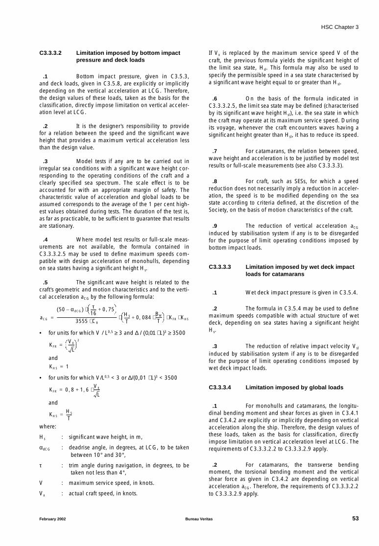
HSC Chapter 3
C3.3.3.2 Limitation imposed by bottom impactpressure and deck loads
.1 Bottom impact pressure, given in C3.5.3,and deck loads, given in C3.5.8, are explicitly or implicitlydepending on the vertical acceleration at LCG. Therefore,the design values of these loads, taken as the basis for theclassification, directly impose limitation on vertical acceler-ation level at LCG.
.2 It is the designer’s responsibility to providefor a relation between the speed and the significant waveheight that provides a maximum vertical acceleration lessthan the design value.
.3 Model tests if any are to be carried out inirregular sea conditions with a significant wave height cor-responding to the operating conditions of the craft and aclearly specified sea spectrum. The scale effect is to beaccounted for with an appropriate margin of safety. Thecharacteristic value of acceleration and global loads to beassumed corresponds to the average of the 1 per cent high-est values obtained during tests. The duration of the test is,as far as practicable, to be sufficient to guarantee that resultsare stationary.
.4 Where model test results or full-scale meas-urements are not available, the formula contained inC3.3.3.2.5 may be used to define maximum speeds com-patible with design acceleration of monohulls, dependingon sea states having a significant height Hs.
.5 The significant wave height is related to thecraft’s geometric and motion characteristics and to the verti-cal acceleration aCG by the following formula:
• for units for which V / L0,5 ≥ 3 and ∆ / (0,01 ⋅ L)3 ≥ 3500
and
• for units for which V/L0,5 < 3 or ∆/(0,01 ⋅ L)3 < 3500
and
where:
Hs : significant wave height, in m,
αdCG : deadrise angle, in degrees, at LCG, to be takenbetween 10° and 30°,
τ : trim angle during navigation, in degrees, to betaken not less than 4°,
V : maximum service speed, in knots.
Vx : actual craft speed, in knots.
If Vx is replaced by the maximum service speed V of thecraft, the previous formula yields the significant height ofthe limit sea state, Hsl. This formula may also be used tospecify the permissible speed in a sea state characterised bya significant wave height equal to or greater than Hsl.
.6 On the basis of the formula indicated inC3.3.3.2.5, the limit sea state may be defined (characterisedby its significant wave height Hsl), i.e. the sea state in whichthe craft may operate at its maximum service speed. Duringits voyage, whenever the craft encounters waves having asignificant height greater than Hsl, it has to reduce its speed.
.7 For catamarans, the relation between speed,wave height and acceleration is to be justified by model testresults or full-scale measurements (see also C3.3.3.3).
.8 For craft, such as SESs, for which a speedreduction does not necessarily imply a reduction in acceler-ation, the speed is to be modified depending on the seastate according to criteria defined, at the discretion of theSociety, on the basis of motion characteristics of the craft.
.9 The reduction of vertical acceleration aCG
induced by stabilisation system if any is to be disregardedfor the purpose of limit operating conditions imposed bybottom impact loads.
C3.3.3.3 Limitation imposed by wet deck impactloads for catamarans
.1 Wet deck impact pressure is given in C3.5.4.
.2 The formula in C3.5.4 may be used to definemaximum speeds compatible with actual structure of wetdeck, depending on sea states having a significant heightHs.
.3 The reduction of relative impact velocity Vsl
induced by stabilisation system if any is to be disregardedfor the purpose of limit operating conditions imposed bywet deck impact loads.
C3.3.3.4 Limitation imposed by global loads
.1 For monohulls and catamarans, the longitu-dinal bending moment and shear forces as given in C3.4.1and C3.4.2 are explicitly or implicitly depending on verticalacceleration along the ship. Therefore, the design values ofthese loads, taken as the basis for classification, directlyimpose limitation on vertical acceleration level at LCG. Therequirements of C3.3.3.2.2 to C3.3.3.2.9 apply.
.2 For catamarans, the transverse bendingmoment, the torsional bending moment and the verticalshear force as given in C3.4.2 are depending on verticalacceleration aCG. Therefore, the requirements of C3.3.3.2.2to C3.3.3.2.9 apply.
aCG
50 α dCG–( ) τ16------ 0 75,+
⋅
3555 CB⋅----------------------------------------------------------------- HS
T------ 0 084,
BW
T-------⋅+
KFR KHS⋅ ⋅ ⋅=
KFRVX
L-------
2
=
KHS 1=
KFR 0 8, 1 6,VX
L-------⋅+=
KHSHS
T------=
February 2002 Bureau Veritas 53

HSC Chapter 3
.3 For SWATH craft, the global loads as givenin C3.4.3 are not depending on ship motions.
.4 For ships with length greater than 100m, therelation between vertical acceleration along the ship andglobal loads are to be ascertained on basis of results ofmodel tests and/or full-scale measurements or by numericalsimulations, as indicated in C3.3.3.2.
.5 The reduction of vertical acceleration alongthe ship induced by stabilisation system if any is to be disre-garded for the purpose of limit operating conditionsimposed by global loads.
C3.3.3.5 Hull monitoring
.1 The Society may require a hull monitoringsystem to be fitted on board, allowing to monitor and dis-play in real time the vertical acceleration and any othersensitive parameter with respect to the strength.
.2 The information is to be available at thewheelhouse and displayed in a clear format allowing tocompare with design values.
.3 When a hull monitoring system is requested,its specification is to be submitted for review.
C3.4 Overall loads
C3.4.1 Monohulls
C3.4.1.1 General
.1 As a rule, only longitudinal vertical bendingmoment and shear force are to be considered formonohulls.
.2 For large craft, values from model tests, orhydrodynamic calculations, may be taken into account,after agreement of the Society on the methodology, the seaconditions and the loading cases. in such cases, valuesgiven in C3.4.1.2 must be considered as short term 1/100°values.
C3.4.1.2 Bending moment and shear force
.1 General
.1 The values of the longitudinal bending momentand shear force are given, in first approxima-tion, by the formula in C3.4.1.2.2, C3.4.1.2.3and C3.4.1.2.4.
.2 The total bending moments MblH, in hoggingconditions, and MblS, in sagging conditions, inkN.m, are to be taken as the greatest of thosegiven by the formulae in C3.4.1.2.2 andC3.4.1.2.3.
For ships having L > 100 m, only the formula inC3.4.1.2.3 is generally to be applied; the for-mula in C3.4.1.2.2 is to be applied whendeemed necessary by the Society on the basis ofthe motion characteristics of the ship. The totalshear forces Tbl, in kN, is given by the formulain C3.4.1.2.4.
.3 The longitudinal distribution of the total bend-ing moment MblH and MblS is given inC3.4.1.2.5.
.4 If the actual distribution of weights along thecraft is known, a more accurate calculation maybe carried out according to the procedure inC3.4.1.2.6. the Society reserves the right torequire calculation to be carried out accordingto C3.4.1.2.6 whenever it deems necessary.
.5 Rule requirements are reminded in TableC3.4.1.
Table C3.4.1
Ships Applicable requirements
L ≤ 100 m All casesBending moment C3.4.1.2.2 or C3.4.1.2.3 whichever is the greater
Shear force C3.4.1.2.4
L ≤ 100 mAlternatively, when actualdistribution of weights is known
Bending moment and shear force C3.4.1.2.6
L > 100 m Normal casesBending moment C3.4.1.2.3
Shear force C3.4.1.2.4
L > 100 mSpecial cases (when deemednecessary by the Society)
Bending moment C3.4.1.2.2 or C3.4.1.2.3 whichever is the greater
Shear force C3.4.1.2.4
L > 100 mAlternatively, when actualdistribution of weights is known
Bending moment and shear force C3.4.1.2.6
54 Bureau Veritas February 2002
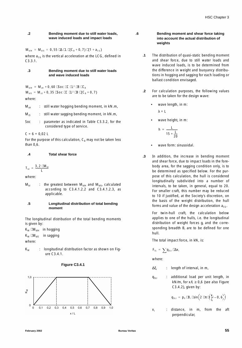
HSC Chapter 3
.2 Bending moment due to still water loads,wave induced loads and impact loads
where aCG is the vertical acceleration at the LCG, defined inC3.3.1.
.3 Bending moment due to still water loadsand wave induced loads
where:
MsH : still water hogging bending moment, in kN.m,
MsS : still water sagging bending moment, in kN.m,
Soc : parameter as indicated in Table C3.3.2, for theconsidered type of service.
C = 6 + 0,02 L
For the purpose of this calculation, CB may not be taken lessthan 0,6.
.4 Total shear force
where:
Mbl : the greatest between MblH and MblS, calculatedaccording to C3.4.1.2.2 and C3.4.1.2.3, asapplicable.
.5 Longitudinal distribution of total bendingmoment
The longitudinal distribution of the total bending momentsis given by:
KM ⋅ MblH in hogging
KM ⋅ MblS in sagging
where:
KM : longitudinal distribution factor as shown on Fig-ure C3.4.1.
Figure C3.4.1
.6 Bending moment and shear force takinginto account the actual distribution ofweights
.1 The distribution of quasi-static bending momentand shear force, due to still water loads andwave induced loads, is to be determined fromthe difference in weight and buoyancy distribu-tions in hogging and sagging for each loading orballast condition envisaged.
.2 For calculation purposes, the following valuesare to be taken for the design wave:
• wave length, in m:
λ = L
• wave height, in m:
• wave form: sinusoidal.
.3 In addition, the increase in bending momentand shear force, due to impact loads in the fore-body area, for the sagging condition only, is tobe determined as specified below. For the pur-pose of this calculation, the hull is consideredlongitudinally subdivided into a number ofintervals, to be taken, in general, equal to 20.For smaller craft, this number may be reducedto 10 if justified, at the Society’s discretion, onthe basis of the weight distribution, the hullforms and value of the design acceleration aCG.
For twin-hull craft, the calculation belowapplies to one of the hulls, i.e. the longitudinaldistribution of weight forces gi and the corre-sponding breadth Bi are to be defined for onehull.
The total impact force, in kN, is:
where:
∆ξi : length of interval, in m,
qSLi : additional load per unit length, inkN/m, for x/L ≥ 0,6 (see also FigureC3.4.2), given by:
xi : distance, in m, from the aftperpendicular,
MblH MblS 0 55 ∆ L CB 0 7,+( ) 1 aCG+( )⋅ ⋅ ⋅ ⋅,= =
MblH MsH 0 60 Soc C L2 B CB⋅ ⋅ ⋅ ⋅ ⋅,+=
MblS MsS 0 35 Soc C L2 B CB 0 7,+( )⋅ ⋅ ⋅ ⋅ ⋅,+=
Tbl3 2, Mb l⋅
L----------------------=
0
1,0
0,50,40,30,20,1 1,00,90,80,70,60
x / L
KM
h L
15 L20------+
-------------------=
FSL qSLi xi∆⋅=
qSLi p0 Bi 2 π xi
L---- 0 6,–
⋅ ⋅ sin⋅ ⋅=
February 2002 Bureau Veritas 55

HSC Chapter 3
Figure C3.4.2
Bi : craft breadth, in m, at uppermostdeck;
(xi and Bi to be measured at the cen-tre of interval i),
p0 : maximum hydrodynamic pressure,in kN/m2, equal to:
av1 : vertical design acceleration at theforward perpendicular, as definedin C3.3,
G : weight force, in kN, equal to:
gi : weight per unit length, in kN/m, ofinterval i; for twin-hull craft, gi is tobe defined for one hull,
xW : distance, in m, of LCG from themidship perpendicular, equal to:
r0 : radius of gyration, in m, of weightdistribution, equal to:
normally 0,2 L < r0 < 0,25 L (guid-ance value)
xSL : distance, in m, of centre of surfaceFSL from the midship perpendicular,given by:
fSL : surface, in m2, equal to:
.4 The resulting load distribution qsi, in kN/m, forthe calculation of the impact induced saggingbending moment and shear force is:
(a) For x/L < 0,6:qsi = qbi = gi ⋅ avi
where:
avi : total dimensionless verticalacceleration at interval i, equalto:
ah : acceleration due to heavingmotion, equal to:
ap : acceleration due to pitchingmotion, in m-1, equal to:
ah and ap are relative to g
(b) For x/L ≥ 0,6:qsi = qbi − qSLi
.5 The impact induced sagging bending momentand shear force are obtained by integration ofthe load distribution qsi along the hull. They areto be added to the respective values calculatedaccording to C3.4.1.3.1 in order to obtain thetotal bending moment and shear force due tostill water loads, wave induced loads andimpact loads.
C3.4.2 Catamarans
C3.4.2.1 General
.1 The values of the longitudinal bendingmoment and shear force are given by the formulae inC3.4.1.2.
.2 For catamarans, the hull connecting struc-tures are to be checked for load conditions specified inC3.4.2.2 and C3.4.2.3. These load conditions are to beconsidered as acting separately.
AP
0,1L0,5L
XSL
LFP
FSL
C = Lav0
av0 + av1
av0avi
av1
qbi= g x a
i vi
p0av1 G r0 xW
2–( )⋅ ⋅fSL r0
2 0 5 L xSL xW–( ) xSL xW⋅–⋅ ⋅,+( )⋅------------------------------------------------------------------------------------------------=
G gi xi∆⋅=
xW
gi xi∆ xi⋅ ⋅( )
gi xi∆⋅( )------------------------------------- 0 5 L⋅,–=
r0
gi xi∆ xi 0 5L,–( )2⋅ ⋅
gi xi∆⋅-----------------------------------------------------------
0 5,
=
xSL1fSL
----- xi∆ xi Bi⋅ ⋅ 2π xi
L---- 0 6,–
⋅
sin 0 5L,–⋅=
fSL xi∆ Bi⋅ 2π xi
L---- 0 6,–
⋅
sin⋅=
avi ah ap xi 0 5L,–( )⋅+=
ahFSL
G-------
r02 xSL xW⋅–r0
2 xW2–
---------------------------- ⋅=
apFSL
G-------
xSL xW–r0
2 xW2–
------------------- ⋅=
56 Bureau Veritas February 2002
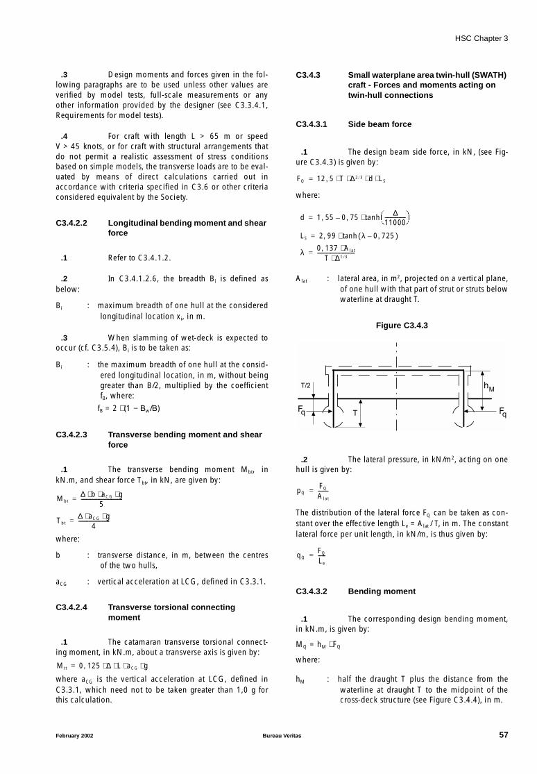
HSC Chapter 3
.3 Design moments and forces given in the fol-lowing paragraphs are to be used unless other values areverified by model tests, full-scale measurements or anyother information provided by the designer (see C3.3.4.1,Requirements for model tests).
.4 For craft with length L > 65 m or speedV > 45 knots, or for craft with structural arrangements thatdo not permit a realistic assessment of stress conditionsbased on simple models, the transverse loads are to be eval-uated by means of direct calculations carried out inaccordance with criteria specified in C3.6 or other criteriaconsidered equivalent by the Society.
C3.4.2.2 Longitudinal bending moment and shearforce
.1 Refer to C3.4.1.2.
.2 In C3.4.1.2.6, the breadth Bi is defined asbelow:
Bi : maximum breadth of one hull at the consideredlongitudinal location xi, in m.
.3 When slamming of wet-deck is expected tooccur (cf. C3.5.4), Bi is to be taken as:
Bi : the maximum breadth of one hull at the consid-ered longitudinal location, in m, without beinggreater than B/2, multiplied by the coefficientfB, where:
fB = 2 ⋅ (1 − Βw/Β)
C3.4.2.3 Transverse bending moment and shearforce
.1 The transverse bending moment Mbt, inkN.m, and shear force Tbt, in kN, are given by:
where:
b : transverse distance, in m, between the centresof the two hulls,
aCG : vertical acceleration at LCG, defined in C3.3.1.
C3.4.2.4 Transverse torsional connectingmoment
.1 The catamaran transverse torsional connect-ing moment, in kN.m, about a transverse axis is given by:
where aCG is the vertical acceleration at LCG, defined inC3.3.1, which need not to be taken greater than 1,0 g forthis calculation.
C3.4.3 Small waterplane area twin-hull (SWATH)craft - Forces and moments acting ontwin-hull connections
C3.4.3.1 Side beam force
.1 The design beam side force, in kN, (see Fig-ure C3.4.3) is given by:
where:
Alat : lateral area, in m2, projected on a vertical plane,of one hull with that part of strut or struts belowwaterline at draught T.
Figure C3.4.3
.2 The lateral pressure, in kN/m2, acting on onehull is given by:
The distribution of the lateral force FQ can be taken as con-stant over the effective length Le = Alat / T, in m. The constantlateral force per unit length, in kN/m, is thus given by:
C3.4.3.2 Bending moment
.1 The corresponding design bending moment,in kN.m, is given by:
MQ = hM ⋅ FQ
where:
hM : half the draught T plus the distance from thewaterline at draught T to the midpoint of thecross-deck structure (see Figure C3.4.4), in m.
Mbt∆ b aCG g⋅ ⋅ ⋅
5--------------------------------=
Tbt∆ aCG g⋅ ⋅
4------------------------=
Mtt 0 125 ∆ L aCG g⋅ ⋅ ⋅ ⋅,=
FQ 12 5 T ∆2 3/ d LS⋅ ⋅ ⋅ ⋅,=
d 1 55 0 75, ∆11000----------------
tanh⋅–,=
LS 2 99 λ 0 725,–( )tanh⋅,=
λ 0 137 Alat⋅,T ∆1 3/⋅
-----------------------------=
TFq
T/2
Fq
hM
pQFQ
Alat
--------=
qQFQ
Le
------=
February 2002 Bureau Veritas 57
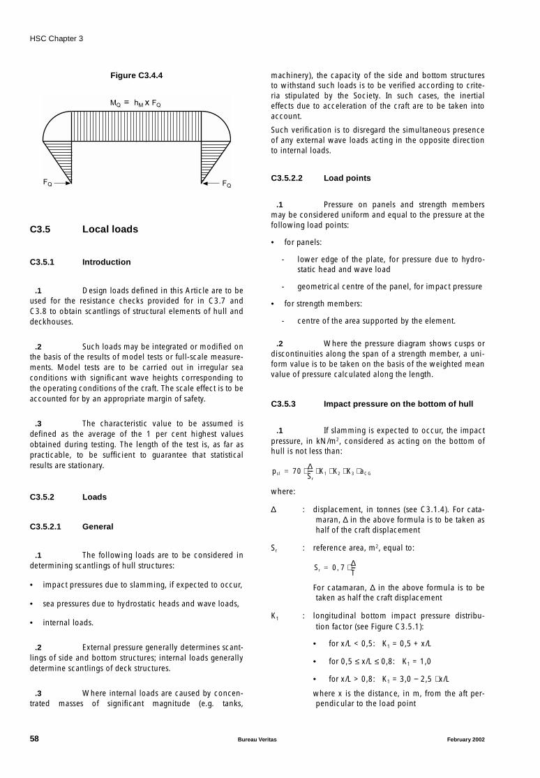
HSC Chapter 3
Figure C3.4.4
C3.5 Local loads
C3.5.1 Introduction
.1 Design loads defined in this Article are to beused for the resistance checks provided for in C3.7 andC3.8 to obtain scantlings of structural elements of hull anddeckhouses.
.2 Such loads may be integrated or modified onthe basis of the results of model tests or full-scale measure-ments. Model tests are to be carried out in irregular seaconditions with significant wave heights corresponding tothe operating conditions of the craft. The scale effect is to beaccounted for by an appropriate margin of safety.
.3 The characteristic value to be assumed isdefined as the average of the 1 per cent highest valuesobtained during testing. The length of the test is, as far aspracticable, to be sufficient to guarantee that statisticalresults are stationary.
C3.5.2 Loads
C3.5.2.1 General
.1 The following loads are to be considered indetermining scantlings of hull structures:
• impact pressures due to slamming, if expected to occur,
• sea pressures due to hydrostatic heads and wave loads,
• internal loads.
.2 External pressure generally determines scant-lings of side and bottom structures; internal loads generallydetermine scantlings of deck structures.
.3 Where internal loads are caused by concen-trated masses of significant magnitude (e.g. tanks,
machinery), the capacity of the side and bottom structuresto withstand such loads is to be verified according to crite-ria stipulated by the Society. In such cases, the inertialeffects due to acceleration of the craft are to be taken intoaccount.
Such verification is to disregard the simultaneous presenceof any external wave loads acting in the opposite directionto internal loads.
C3.5.2.2 Load points
.1 Pressure on panels and strength membersmay be considered uniform and equal to the pressure at thefollowing load points:
• for panels:
- lower edge of the plate, for pressure due to hydro-static head and wave load
- geometrical centre of the panel, for impact pressure
• for strength members:
- centre of the area supported by the element.
.2 Where the pressure diagram shows cusps ordiscontinuities along the span of a strength member, a uni-form value is to be taken on the basis of the weighted meanvalue of pressure calculated along the length.
C3.5.3 Impact pressure on the bottom of hull
.1 If slamming is expected to occur, the impactpressure, in kN/m2, considered as acting on the bottom ofhull is not less than:
where:
∆ : displacement, in tonnes (see C3.1.4). For cata-maran, ∆ in the above formula is to be taken ashalf of the craft displacement
Sr : reference area, m2, equal to:
For catamaran, ∆ in the above formula is to betaken as half the craft displacement
K1 : longitudinal bottom impact pressure distribu-tion factor (see Figure C3.5.1):
• for x/L < 0,5: K1 = 0,5 + x/L
• for 0,5 ≤ x/L ≤ 0,8: K1 = 1,0
• for x/L > 0,8: K1 = 3,0 − 2,5 ⋅ x/L
where x is the distance, in m, from the aft per-pendicular to the load point
FQ
MQ = hM x FQ
FQ
psl 70∆Sr
---- K1 K2 K3 aCG⋅ ⋅ ⋅ ⋅ ⋅=
Sr 0 7 ∆T---⋅,=
58 Bureau Veritas February 2002
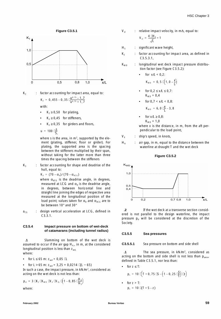
HSC Chapter 3
Figure C3.5.1
K2 : factor accounting for impact area, equal to:
with:
• K2 ≥ 0,50 for plating,
• K2 ≥ 0,45 for stiffeners,
• K2 ≥ 0,35 for girders and floors,
where s is the area, in m2, supported by the ele-ment (plating, stiffener, floor or girder). Forplating, the supported area is the spacingbetween the stiffeners multiplied by their span,without taking for the latter more than threetimes the spacing between the stiffeners
K3 : factor accounting for shape and deadrise of thehull, equal to:
where αdCG is the deadrise angle, in degrees,measured at LCG and αd is the deadrise angle,in degrees, between horizontal line andstraight line joining the edges of respective areameasured at the longitudinal position of theload point; values taken for αd and αdCG are tobe between 10° and 30°
aCG : design vertical acceleration at LCG, defined inC3.3.1.
C3.5.4 Impact pressure on bottom of wet-deckof catamarans (including tunnel radius)
.1 Slamming on bottom of the wet deck isassumed to occur if the air gap HA,, in m, at the consideredlongitudinal position is less than zwd,
where:
• for L ≤ 65 m: zwd = 0,05 ⋅ L
• for L > 65 m: zwd = 3,25 + 0,0214 ⋅ (L − 65)In such a case, the impact pressure, in kN/m2, considered asacting on the wet deck is not less than:
where:
Vsl : relative impact velocity, in m/s, equal to:
HS : significant wave height,
K2 : factor accounting for impact area, as defined inC3.5.3.1,
KWD : longitudinal wet deck impact pressure distribu-tion factor (see Figure C3.5.2):
• for x/L < 0,2:
• for 0,2 ≤ x/L ≤ 0,7:KWD = 0,4
• for 0,7 < x/L < 0,8:
• for x/L ≥ 0,8:KWD = 1,0
where x is the distance, in m, from the aft per-pendicular to the load point,
VX : ship’s speed, in knots,
HA : air gap, in m, equal to the distance between thewaterline at draught T and the wet deck
Figure C3.5.2
.2 If the wet deck at a transverse section consid-ered is not parallel to the design waterline, the impactpressure psl will be considered at the discretion of theSociety.
C3.5.5 Sea pressures
C3.5.5.1 Sea pressure on bottom and side shell
.1 The sea pressure, in kN/m2, considered asacting on the bottom and side shell is not less than psmin,defined in Table C3.5.1, nor less than:
• for z ≤ T:
• for z > T:
K1
1,0
1,00,80 x/L
0,5
0,5
K2 0 455 0 35, u0 75, 1 7,–u0 75, 1 7,+---------------------------⋅–,=
u 100 sSr
----⋅=
K3 70 α d–( ) 70 α dCG–( )⁄=
psl 3 K2 KW D VX VSL⋅ 1 0 85, HA
HS
-------⋅– ⋅ ⋅ ⋅ ⋅=
Vsl4 HS⋅
L-------------- 1+=
KWD 0 5, 1 0, xL---–
⋅=
KWD 6 0, xL---⋅ 3 8,–=
KWD
1,0
1,00,80 x/L0,2 0,7
0,5
0,4
ps 10 T 0 75 S 1 0 25 ST---⋅,–
z⋅–⋅,+
⋅=
ps 10 T S z–+( )⋅=
February 2002 Bureau Veritas 59

HSC Chapter 3
where:
z : vertical distance, in m, from the moulded baseline to load point. z is to be taken positivelyupwards,
S : as given, in m, in Table C3.5.1 with CB takennot greater than 0,5.
Table C3.5.1
.2 Between midship area and fore end(0,5 < x/L < 0,9), ps varies in a linear way as follows:
where psFP is the sea pressure at fore end and psM in midshiparea.
C3.5.5.2 Stern doors and side shell doors
.1 The sea pressures on stern doors and sideshell doors is to be taken according to C3.5.5.1 for scant-lings of plating and secondary members.
.2 The design forces, in kN, considered for thescantlings of primary members are to be not less than:
• external force: Fe = A ⋅ ps
• internal force: Fi = Fo + 10 ⋅ Wwhere:
A : area, in m, of the door opening,
W : mass of the door, in t,
Fp : total packing force in kN. Packing line pressureis normally not to be taken less than 5 N/mm,
Fo : the greater of Fc and 5 ⋅ A (kN),
Fc : accidental force, in kN, due to loose of cargoetc., to be uniformly distributed over the area Aand not to be taken less than 300 kN. For smalldoors, such as bunker doors and pilot doors,the value of Fc may be appropriately reduced.However, the value of Fc may be taken as zero,provided an additional structure such as aninner ramp is fitted, which is capable of pro-tecting the door from accidental forces due toloose cargoes,
ps : sea pressure as defined in C3.5.5.1
.3 The design forces, in kN, considered for thescantlings of securing or supporting devices of doors open-ing outwards are to be not less than:
• external force: Fe = A ⋅ ps
• internal force: Fi = Fo + 10 ⋅ W + Fp
where the parameters are defined in C3.5.5.2.2.
.4 The design forces, in kN, considered for thescantlings of securing or supporting devices of doors open-ing inwards are to be not less than:
• external force: Fe = A ⋅ ps + Fp
• internal force: Fi = Fo + 10 ⋅ Wwhere the parameters are defined in C3.5.5.2.2.
C3.5.6 Sea pressures on front walls of the hull
.1 The pressure, kN/m2, considered as acting onfront walls of the hull (in case of stepped main deck), notlocated at the fore end, is not less than:
where:
x1 : distance, in m, from front walls to the midshipperpendicular (for front walls aft of the midshipperpendicular, x1 is equal to 0),
z1 : distance, in m, from load point to waterline atdraught T.
Where front walls are inclined backwards, the pressure cal-culated above can be reduced to (psF sin α), where α is theangle in degree between front wall and deck.psF is not less than the greater of:3 + (6,5 + 0,06 ⋅ L) ⋅ sin α3 + 2,4 ⋅ aCG
.2 For front walls located at the fore end, thepressure psF will be individually considered by the Society.
C3.5.7 Sea pressures on deckhouses
.1 The pressure, kN/m2, considered as acting onwalls of deckhouses is not less than:
where:
Ksu : coefficient equal to:
• for front walls of a deckhouse locateddirectly on the main deck not at the foreend:Ksu = 6,0
• for unprotected front walls of the secondtier, not located at the fore end:Ksu = 5,0
• for sides of deckhouses, b being thebreadth, in m, of the considereddeckhouse:Ksu = 1,5 + 3,5 b/B (with 3 ≤ K < 5)
• for the other walls:Ksu = 3,0
S psmin
x/L ≥ 0,9
x/L ≤ 0,5
T 0 36 aCGL
CB
-------⋅ ⋅, 3 5 T⋅,≤ ≤ 20 L 75+5
---------------- 35≤ ≤
T 0 60 aCG L⋅ ⋅, 2 5 T⋅,≤ ≤ 10 L 75+10
---------------- 20≤ ≤
ps psFP 2 25 2 5 x L )⁄⋅,–, psFP psM–( )⋅( )–=
psf 6 1 x1
2 L CB 0 1,+( )⋅--------------------------------------+
1 0 045 L 0 38 z1⋅,–⋅,+( )⋅=
psu Ksu 1x1
2 L CB 0 1,+( )⋅--------------------------------------+
1 0 045 L 0 38 z1⋅,–⋅,+( )⋅=
60 Bureau Veritas February 2002
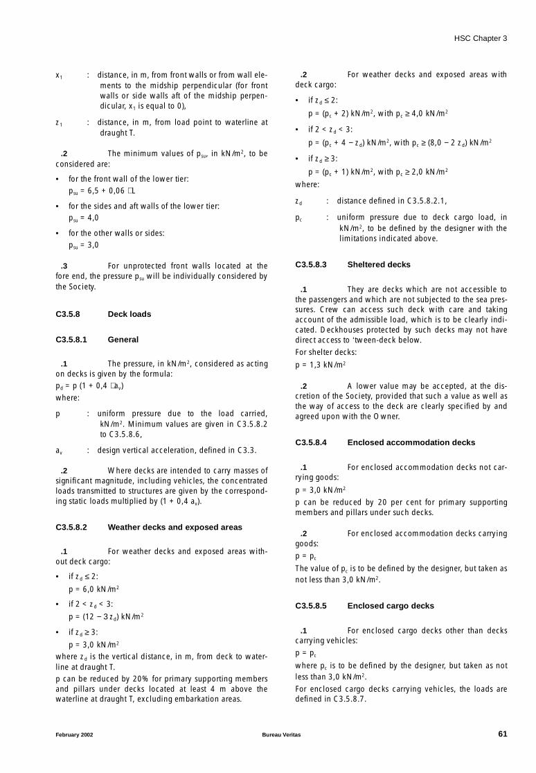
HSC Chapter 3
x1 : distance, in m, from front walls or from wall ele-ments to the midship perpendicular (for frontwalls or side walls aft of the midship perpen-dicular, x1 is equal to 0),
z1 : distance, in m, from load point to waterline atdraught T.
.2 The minimum values of psu, in kN/m2, to beconsidered are:
• for the front wall of the lower tier:psu = 6,5 + 0,06 ⋅ L
• for the sides and aft walls of the lower tier:psu = 4,0
• for the other walls or sides:psu = 3,0
.3 For unprotected front walls located at thefore end, the pressure psu will be individually considered bythe Society.
C3.5.8 Deck loads
C3.5.8.1 General
.1 The pressure, in kN/m2, considered as actingon decks is given by the formula:pd = p (1 + 0,4 ⋅ av)where:
p : uniform pressure due to the load carried,kN/m2. Minimum values are given in C3.5.8.2to C3.5.8.6,
av : design vertical acceleration, defined in C3.3.
.2 Where decks are intended to carry masses ofsignificant magnitude, including vehicles, the concentratedloads transmitted to structures are given by the correspond-ing static loads multiplied by (1 + 0,4 av).
C3.5.8.2 Weather decks and exposed areas
.1 For weather decks and exposed areas with-out deck cargo:
• if zd ≤ 2:
p = 6,0 kN/m2
• if 2 < zd < 3:
p = (12 − 3 zd) kN/m2
• if zd ≥ 3:
p = 3,0 kN/m2
where zd is the vertical distance, in m, from deck to water-line at draught T.p can be reduced by 20% for primary supporting membersand pillars under decks located at least 4 m above thewaterline at draught T, excluding embarkation areas.
.2 For weather decks and exposed areas withdeck cargo:
• if zd ≤ 2:
p = (pc + 2) kN/m2, with pc ≥ 4,0 kN/m2
• if 2 < zd < 3:
p = (pc + 4 − zd) kN/m2, with pc ≥ (8,0 − 2 zd) kN/m2
• if zd ≥ 3:
p = (pc + 1) kN/m2, with pc ≥ 2,0 kN/m2
where:
zd : distance defined in C3.5.8.2.1,
pc : uniform pressure due to deck cargo load, inkN/m2, to be defined by the designer with thelimitations indicated above.
C3.5.8.3 Sheltered decks
.1 They are decks which are not accessible tothe passengers and which are not subjected to the sea pres-sures. Crew can access such deck with care and takingaccount of the admissible load, which is to be clearly indi-cated. Deckhouses protected by such decks may not havedirect access to ‘tween-deck below.For shelter decks:
p = 1,3 kN/m2
.2 A lower value may be accepted, at the dis-cretion of the Society, provided that such a value as well asthe way of access to the deck are clearly specified by andagreed upon with the Owner.
C3.5.8.4 Enclosed accommodation decks
.1 For enclosed accommodation decks not car-rying goods:
p = 3,0 kN/m2
p can be reduced by 20 per cent for primary supportingmembers and pillars under such decks.
.2 For enclosed accommodation decks carryinggoods:p = pc
The value of pc is to be defined by the designer, but taken asnot less than 3,0 kN/m2.
C3.5.8.5 Enclosed cargo decks
.1 For enclosed cargo decks other than deckscarrying vehicles:p = pc
where pc is to be defined by the designer, but taken as notless than 3,0 kN/m2.For enclosed cargo decks carrying vehicles, the loads aredefined in C3.5.8.7.
February 2002 Bureau Veritas 61
HSC Chapter 3
C3.5.8.6 Platforms of machinery spaces
.1 For platforms of machinery spaces:
p = 15,0 kN/m2
C3.5.8.7 Decks carrying vehicles
.1 The scantlings of the structure of decks carry-ing vehicles are to be determined by taking into accountonly the concentrated loads transmitted by the wheels ofvehicles, except in the event of supplementary requirementfrom the designer.
.2 The scantlings under racking effects (e.g. forcombined loading condition 3 defined in C3.6.1.2.9 andC3.6.2.2.9) of the primary structure of decks carrying vehi-cles is to be the greater of the following cases:
• scantlings determined under concentrated loads trans-mitted by the wheels of vehicles,
• scantlings determined under a uniform load pc takennot less than 2,5 kN/m2. This value of pc may beincreased if the structural weight cannot be consideredas negligible, to the satisfaction of the Society.
C3.5.9 Pressures on tank structures
.1 The pressure, in kN/m2, considered as actingon tank structures is not less than the greater of:
where:
h1 : distance, in m, from load point to tank top,
h2 : distance, in m, from load point to top of over-flow or to a point located 1,5 m above the tanktop, whichever is greater,
ρ : liquid density, in t/m3 (1,0 t/m3 for water),
pv : setting pressure, in bars, of pressure relief valve,when fitted.
C3.5.10 Pressures on subdivision bulkheads
.1 The pressure, in kN/m2, considered as actingon subdivision bulkheads is not less than:
psb = 9,81 ⋅ h3
where:
h3 : distance, in m, from load point to bulkhead top.
C3.6 Direct calculations for monohullsand catamarans
C3.6.1 Direct calculations for monohulls
C3.6.1.1 General
.1 Direct calculations generally require to becarried out, in the opinion of the Society, to check primarystructures for craft of length L > 65 m or speed V > 45 knots.
.2 In addition, direct calculations are to be car-ried out to check scantlings of primary structures of craftwhenever, in the opinion of the Society, hull shapes andstructural dimensions are such that scantling formulas inC3.7 and C3.8 are no longer deemed to be effective.
.3 This may be the case, for example, in the fol-lowing situations:
• elements of the primary transverse ring (beam, web andfloor) have very different cross section inertiae, so thatthe boundary conditions for each are not well-defined,
• marked V-shapes, so that floor and web tend to degen-erate into a single element,
• complex, non-conventional geometries,
• presence of significant racking effects (in general onferries),
• structures contributing to longitudinal strength withlarge windows in side walls.
C3.6.1.2 Loads
.1 In general, the loading conditions specifiedin C3.6.1.2.6 to C3.6.1.2.9 below are to be considered.Condition C3.6.1.2.9 is to be checked for craft for which, inthe opinion of the Society, significant racking effects areanticipated (e.g. for ferries).
.2 In relation to special structure or loadingconfigurations, should some loading conditions turn out tobe less significant than others, the former may be ignored atthe discretion of the Society. In the same way, it may benecessary to consider further loading conditions specifiedby the Society in individual cases.
.3 The vertical and transverse accelerations areto be calculated as stipulated in C3.3.
.4 The impact pressure is to be calculated asstipulated in C3.5. For each floor, the K2-factor whichappears in the formula for the impact pressure is to be cal-culated as a function of the area supported by the flooritself.
.5 In three-dimensional analyses, special atten-tion is to be paid to the distribution of weights andbuoyancy and to the dynamic equilibrium of the craft.In the case of three-dimensional analyses, the longitudinaldistribution of impact pressure is to be considered individu-
pt1 9 81, h1 ρ 1 0 4 av⋅,+( ) 100 pv⋅+⋅ ⋅ ⋅=
p12 9 81, h2⋅=
62 Bureau Veritas February 2002

HSC Chapter 3
ally, in the opinion of the Society. In general, the impactpressure is to be considered as acting separately on eachtransverse section of the model, the remaining sectionsbeing subject to the hydrostatic pressure.
.6 Loading conditions in still water
The following loads are to be considered:
• forces caused by weights which are expected to be car-ried in the full load condition, distributed according tothe weight booklet of the craft,
• outer hydrostatic load in still water.
.7 Combined loading condition 1
The following loads are to be considered:
• forces caused by weights which are expected to be car-ried in the full load condition, distributed according tothe weight booklet of the craft,
• forces of inertia due to the vertical acceleration av of thecraft, considered in a downward direction.
.8 Combined loading condition 2
The following loads are to be considered:
• forces caused by weights which are expected to be car-ried in the full load condition, distributed according tothe weight booklet of the craft,
• forces of inertia due to the vertical acceleration av of thecraft, considered in a downward direction,
• impact pressure acting on the bottom of the craft (2cases):
- case 1: symmetrically and according to C3.6.1.2.5,
- case 2: asymmetrically and acting on one side of acomplete compartment between transverse bulk-heads, the other side being subject to hydrostaticload in still water.
.9 Combined loading condition 3
The following loads are to be considered:
• forces caused by weights which are expected to be car-ried in the full load condition, distributed according tothe weight booklet of the craft,
• forces of inertia due to the transverse acceleration of thecraft.
C3.6.1.3 Structural model
.1 Primary structures of craft of this type mayusually be modelled with beam elements, according to cri-teria stipulated by the Society. When, however, grounds forthe admissibility of this model are lacking, or when thegeometry of the structures gives reason to suspect the pres-ence of high stress concentrations, finite element analysesare necessary.
.2 In general, the extent of the model is to besuch as to allow analysis of the behaviour of the main struc-tural elements and their mutual effects.
.3 In craft dealt with by these Rules, the stiffnessof longitudinal primary members (girders and stringers) is, atleast outside the machinery space area, generally negligiblecompared with the stiffness of transverse structures (beams,floors and webs), or their presence may be taken account ofby suitable boundary conditions. It is therefore acceptable,in general, to examine primary members in this area of thehull by means of plane analyses of transverse rings.
.4 In cases where such approximation is notacceptable, the model adopted is to be three-dimensionaland is to include the longitudinal primary members.
.5 When racking behaviour is investigated andloads thus act in the transverse direction (loading condition3), special attention is to be devoted to modelling of contin-uous decks and platforms. Such continuous elements, if ofsufficient stiffness in the horizontal plane and if sufficientlyrestrained by the fore- and after-bodies, may withstandtransverse deformations of primary rings.
In such cases, taking for granted the provisions above, it isstill permissible to examine bidimensional rings, by simulat-ing the presence of decks and platforms with horizontalsprings according to criteria specified by the Society.
C3.6.1.4 Boundary conditions
.1 Depending upon the loading conditions con-sidered, the following boundary conditions are to beassigned:
(a) Loading condition in still water and combined loadingconditions 1 and 2
• horizontal and transverse restraints, in way of thecrossing point of bottom and side shells, if the anglebetween the two shells is less than approximately135°,
• horizontal and transverse restraints, in way of keel, ifthe bottom/side angle is greater than approximately135°.
(b) Combined loading condition 3
The vertical and horizontal resultants of the loads, ingeneral other than zero, are to be balanced by introduc-ing two vertical forces and two horizontal forces at thefore and aft ends of the model, distributed on the shellsaccording to the bidimensional flow theory for shearstresses, which are equal and opposite to half the verti-cal and horizontal resultants of the loads.
.2 Where a plane model is adopted, the result-ants are to be balanced by vertical and horizontal forces,distributed as specified above and acting on the plane of themodel itself.
February 2002 Bureau Veritas 63
HSC Chapter 3
C3.6.1.5 Checking criteria
.1 For metal structures, the stresses given by theabove calculations are to be not greater than the followingallowable values, in N/mm2:
• bending stress:
• shear stress:
• Von Mises equivalent bending stress:
where:
K : material factor defined in C3.2
f’m : coefficient depending on the material:
• 1,00 for steel structures
• 2,15 for aluminium alloy structures
fs : safety coefficient, to be assumed:
• 1,00 for combined loading conditions
• 1,25 for loading condition in still water.
.2 The compressive values of normal stressesand shear stresses are not to exceed the values of the criticalstresses for plates and stiffeners calculated according toC3.7.5.
.3 In structural elements also subject to highlongitudinal hull girder stresses, allowable and criticalstresses are to be reduced, according to criteria specified bythe Society.
.4 For non-metal structures, allowable stressesare to be defined according to criteria specified by theSociety.
C3.6.2 Direct calculations for catamarans
C3.6.2.1 General
.1 Direct calculations generally require to becarried out, at the discretion of the Society, to check pri-mary structures and structures connecting the two hulls forcraft of length L > 65 m or speed V > 45 knots.
.2 In addition, as specified in C3.4.2, direct cal-culations are to be carried out to check structuresconnecting the two hulls for craft in which structuralarrangements do not allow a realistic assessment of theirstress level, based upon simple models and on the formulaeset out in C3.4.2.
C3.6.2.2 Loads
.1 In general, the loading conditions specifiedin C3.6.2.2.6 to C3.6.2.2.9 below are to be considered.
Condition C3.6.2.2.6 applies to a still water static conditioncheck.
Conditions C3.6.2.2.7 and C3.6.2.2.8 apply to the checkon structures connecting the two hulls. ConditionC3.6.2.2.8 requires checking only for craft of L > 65 m or V> 45 knots.
Condition C3.6.2.2.9 is to be checked in craft for which, inthe opinion of the Society, significant racking effects areexpected (e.g. ferries).
.2 In relation to special structure or loadingconfigurations, should some loading conditions turn out tobe less significant than others, the former may be ignored,at the discretion of the Society. In the same way, it may benecessary to consider further loading conditions specifiedby the Society in individual cases.
.3 Vertical and transverse accelerations are tobe calculated as stipulated in C3.3.
.4 The impact pressure is to be calculated asstipulated in C3.5. For each floor, the K2-factor whichappears in the formula for the impact pressure is to be cal-culated as a function of the area supported by the flooritself.
.5 In three-dimensional analyses, special atten-tion is to be paid to the distribution of weights andbuoyancy and the dynamic equilibrium of the craft.
In the case of three-dimensional analyses, the longitudinaldistribution of impact pressure is to be considered individu-ally, in the opinion of the Society. In general, the impactpressure is to be considered as acting separately on eachtransverse section of the model, the remaining sectionsbeing loaded by the hydrostatic pressure.
.6 Loading conditions in still water
The following loads are to be considered:
• forces caused by weights which are expected to be car-ried in the full load condition, distributed according tothe weight booklet of the craft,
• outer hydrostatic load in still water.
.7 Combined loading condition 1
The following loads are to be considered:
• forces caused by weights which are expected to be car-ried in the full load condition, distributed according tothe weight booklet of the craft,
• forces of inertia due to the vertical acceleration av of thecraft, considered in a downward direction.
σam150
K f'm fs⋅ ⋅---------------------=
τ am90
K f'm fs⋅ ⋅---------------------=
σeq am,190
K f'm fs⋅ ⋅---------------------=
64 Bureau Veritas February 2002
HSC Chapter 3
.8 Combined loading condition 2
The following loads are to be considered:
• forces caused by weights which are expected to be car-ried in the full load condition, distributed according tothe weight booklet of the craft,
• forces of inertia due to the vertical acceleration av of thecraft, considered in a downward direction,
• impact pressure acting hemisymmetrically on one of thetwo halves of the hull bottom.
.9 Combined loading condition 3
The following loads are to be considered:
• forces caused by weights which are expected to be car-ried in the full load condition, distributed according tothe weight booklet of the craft,
• forces of inertia due to the transverse acceleration of thecraft.
C3.6.2.3 Structural model
.1 In general, primary structures of craft of thistype are to be modelled with finite element schematizationsadopting a medium size mesh.In the opinion of the Society, detailed analyses with finemesh are required for areas where stresses, calculated withmedium-mesh schematizations, exceed allowable limitsand the type of structure gives reason to suspect the pres-ence of high stress concentrations.
.2 In general, the extent of the model is to besuch as to allow the analysis of the behaviour of the mainstructural elements and their mutual effects.
.3 In craft dealt with by these Rules, the stiffnessof longitudinal primary members (girders and stringers) is, atleast outside the machinery space area, generally negligiblecompared with the stiffness of transverse structures (beams,floors and webs), or their presence may be taken account ofby suitable boundary conditions. It is therefore permissible,in general, to examine primary members in this area of thehull by means of plane analyses of transverse rings.
.4 In cases where such approximation is notpermissible, the model adopted is to be three-dimensionaland is to include the longitudinal primary members.
.5 When racking behaviour is investigated andloads thus act in the transverse direction (loading conditions2 and 3), special attention is to be devoted to modelling ofcontinuous decks and platforms. Such continuous elements,if having sufficient stiffness in the horizontal plane and ifsufficiently restrained by the fore- and after-bodies, maywithstand transverse deformations of primary rings.In such cases, taking for granted the provisions above, it isstill permissible to examine bidimensional rings, by simulat-ing the presence of decks and platforms with horizontalsprings according to criteria specified by the Society.
C3.6.2.4 Boundary conditions
.1 Depending upon the loading conditions con-sidered, the following boundary conditions may beassigned:
(a) Loading condition in still waterThe vertical resultant of loads, in general other thanzero, is to be balanced by introducing two verticalforces at the fore and aft ends of the model, both distrib-uted on the shells according to the bidimensional flowtheory for shear stresses, which are equal and oppositeto half the vertical resultant of the loads.Where a plane model is adopted, the vertical resultant isto be balanced by a single force, distributed as specifiedabove and acting on the plane of the model itself.
(b) Combined loading condition 1A vertical restraint is to be imposed in way of the keel ofeach hull.
(c) Combined loading conditions 2 and 3The vertical and horizontal resultants of the loads, ingeneral other than zero, are to be balanced by introduc-ing two vertical forces and two horizontal forces at thefore and aft ends of the model, distributed on the shellsaccording to the bidimensional flow theory for shearstresses, which are equal and opposite to half the verti-cal and horizontal resultants of the loads.
.2 Where a plane model is adopted, the result-ants are to be balanced by vertical and horizontal forces,distributed as specified above and acting on the plane of themodel itself.
C3.6.2.5 Checking criteria
.1 For metal structures, the stresses given by theabove calculations are to be not greater than the followingallowable values, in N/mm2:
• bending stress:
• shear stress:
• Von Mises equivalent stress:
where:
K : material factor defined in C3.2,
f’m : coefficient depending on the material:
• 1,00 for steel structures
• 2,15 for aluminium alloy structures,
fs : safety coefficient, to be assumed:
• 1,00 for combined loading conditions
• 1,25 for loading condition in still water.
σ 150K f'm fs⋅ ⋅---------------------=
τ 90K f'm fs⋅ ⋅---------------------=
σall190
K f'm fs⋅ ⋅---------------------=
February 2002 Bureau Veritas 65

HSC Chapter 3
.2 The compressive values of normal stressesand the shear stresses are not to exceed the values of thecritical stresses for plates and stiffeners calculated accord-ing to C3.7.5.
.3 In structural elements also subject to highlongitudinal and transversal hull girder stresses, allowableand critical stresses are to be reduced, according to criteriaspecified by the Society.
.4 For non-metal structures, allowable stressesare to be defined according to criteria specified by theSociety.
C3.7 Steel and aluminium alloy craft
C3.7.1 Introduction
.1 This article stipulates requirements for thescantlings of hull structures (plating, stiffeners, primary sup-porting members). The loads acting on such structures areto be calculated in accordance with the provisions of C3.5.
.2 In general, for craft length L > 65 m or speedV > 45 knots, the scantlings of transverse structures are tobe verified also by direct calculations carried out in accord-ance with C3.6.
.3 For all other craft, the Society may, at its dis-cretion and as an alternative to the requirements of thisarticle, accept scantlings for transverse structures of the hullbased on direct calculations in accordance with C3.6.
C3.7.2 Definitions and symbols
.1 The definitions and symbols used are the fol-lowing ones:
rule bracket: a bracket with arms equal to /8, being thespan of the connected stiffener. Where thebracket connects two different types of stiffen-ers (frame and beam, bulkhead web andlongitudinal stiffener, etc.) the value of is tobe that of the member with the greater span, oraccording to criteria specified by the Society,
t : thickness, in mm, of plating and deck panels,
Z : section modulus, in cm3, of stiffeners and pri-mary supporting members,
s : spacing of stiffeners, in m, measured along theplating,
: overall span of stiffeners, in m, i.e. the distancebetween the supporting elements at the ends ofthe stiffeners (see Figure C3.7.1),
S : conventional scantling span of primary support-ing members, in m, to be taken as given in theexamples in Figure C3.7.2. Special considera-tion is to be given to conditions different fromthose shown.
In no case is S to be less than (1,1 S0), S0 beingthe distance between the internal ends of theconventional brackets as indicated in FigureC3.7.2 or, if there are no brackets, between theends of the members,
Figure C3.7.1 Examples of spans of ordinary stiffeners
Note: the connections with end brackets shown in this Figure are relevant to end brackets with Rule dimensions.
66 Bureau Veritas February 2002
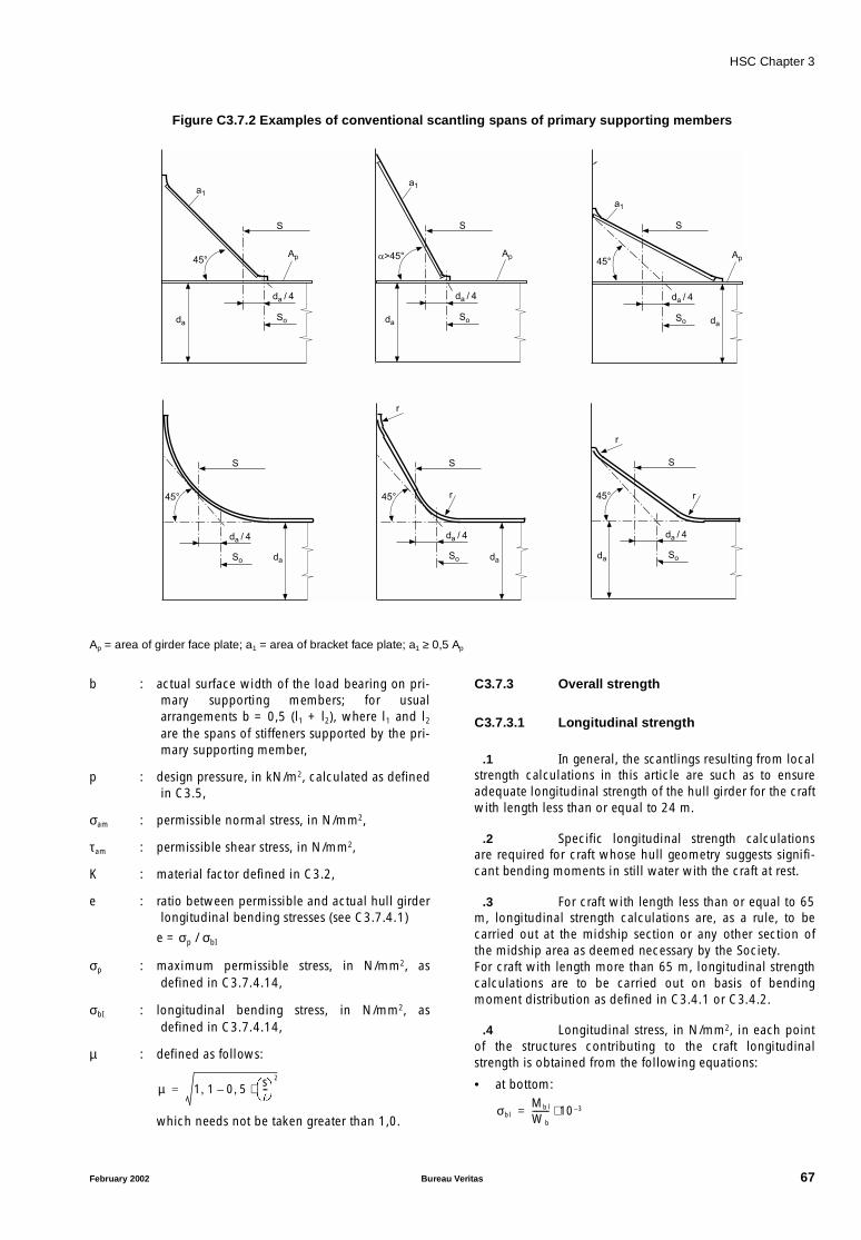
HSC Chapter 3
Figure C3.7.2 Examples of conventional scantling spans of primary supporting members
Ap = area of girder face plate; a1 = area of bracket face plate; a1 ≥ 0,5 Ap
b : actual surface width of the load bearing on pri-mary supporting members; for usualarrangements b = 0,5 (l1 + l2), where l1 and l2
are the spans of stiffeners supported by the pri-mary supporting member,
p : design pressure, in kN/m2, calculated as definedin C3.5,
σam : permissible normal stress, in N/mm2,
τam : permissible shear stress, in N/mm2,
K : material factor defined in C3.2,
e : ratio between permissible and actual hull girderlongitudinal bending stresses (see C3.7.4.1)
e = σp / σbI
σp : maximum permissible stress, in N/mm2, asdefined in C3.7.4.14,
σbI : longitudinal bending stress, in N/mm2, asdefined in C3.7.4.14,
µ : defined as follows:
which needs not be taken greater than 1,0.
C3.7.3 Overall strength
C3.7.3.1 Longitudinal strength
.1 In general, the scantlings resulting from localstrength calculations in this article are such as to ensureadequate longitudinal strength of the hull girder for the craftwith length less than or equal to 24 m.
.2 Specific longitudinal strength calculationsare required for craft whose hull geometry suggests signifi-cant bending moments in still water with the craft at rest.
.3 For craft with length less than or equal to 65m, longitudinal strength calculations are, as a rule, to becarried out at the midship section or any other section ofthe midship area as deemed necessary by the Society.For craft with length more than 65 m, longitudinal strengthcalculations are to be carried out on basis of bendingmoment distribution as defined in C3.4.1 or C3.4.2.
.4 Longitudinal stress, in N/mm2, in each pointof the structures contributing to the craft longitudinalstrength is obtained from the following equations:
• at bottom:
da
a1
Ap
da / 4
So
45°
S
da
a1
Ap
da / 4
So
a>45°
S
a1
Ap
da / 4
So
45°
S
da
da
da / 4
So
45°
S
da
da / 4
So
45°
S
r
r
da
da / 4
So
45°
S
r
r
µ 1 1, 0 5 s--
2
⋅,–=
σblMb l
Wb
-------- 10 3–⋅=
February 2002 Bureau Veritas 67
HSC Chapter 3
• at main deck:
• at height z above the bottom:
where:
Mbl : total bending moment, in kN.m, defined inC3.4.1 or C3.4.2,
Wb, Wd : section modulus, in m3, respectively at bottomand main deck at the stress calculation point ofthe craft section under consideration. In thesection modulus calculation, all the elementscontributing to longitudinal strength are to beconsidered, including long deckhouses, asappropriate.
The values of stress σbI are not to exceed σp, with:
• steel structures:
σp = 150/K (N/mm2)
• aluminium alloy structures:
σp = 70/K (N/mm2).
.5 Moreover, the compressive values of σ arenot to exceed the values of critical stresses for plates andstiffeners calculated according to C3.7.5 and C3.7.6.
C3.7.3.2 Transverse strength of catamaran
.1 The equivalent Von Mises stresses obtainedfor load conditions in C3.4.2.3 and C3.4.3.2 are not toexceed the following values:
• steel structures:
σp = 175/K (N/mm2)
• aluminium alloy structures:
σp = 75/K (N/mm2).
.2 The compressive values of normal stressesand the shear stresses are not to exceed the values of criticalstresses for plates and stiffeners calculated according toC3.7.5 and C3.7.6.
.3 In general, the bottom of the cross-deck is tobe constituted by continuous plating for its entire longitudi-nal and transverse extension. Alternative solutions may,however, be examined by the Society on the basis of con-siderations pertaining to the height of the cross-deck abovethe waterline and to the motion characteristics of the craft.
.4 In the special case of catamaran, when thestructure connecting both hulls is formed by a deck withsingle plating stiffened by n reinforced beams, the normaland shear stresses in the beams for the load condition inC3.4.2.4 can be calculated as indicated in C3.7.3.3.
.5 For craft with L > 65 m or speed V > 45 mknots, or for those craft whose structural arrangements donot permit a realistic assessment of stress conditions basedon simple models, the transverse strength is to be checkedby means of direct calculations carried out in accordancewith the criteria specified in article C3.6.
C3.7.3.3 Transverse strength in the special caseof catamaran craft when the structureconnecting both hulls is formed by adeck with single plate stiffened by nreinforced beams over the deck
.1 Referring to Figure C3.7.3, G is the centre ofthe stiffnesses ri of the n beams. Its position is defined by:
where:
a : abscissa, in m, of the centre G with respect toan arbitrarily chosen origin 0,
ri : stiffness, in N/m, of the beam i, equal to:
Ei : Young’s modulus, in N/mm2, of the beam i,
Ii : bending inertia, in m4, of the beam i,
Si : span, in m, of the beam i between the innerfaces of the hulls,
xi : abscissa, in m, of the beam i with respect to theorigin 0.
If Fi, in N, is the force taken over by the beam i, the deflec-tion yi, in m, of the hull in way of the beam i, is:
di : abscissa, in m, of the beam i in relation to G:
di = xi − a,
ω : rotation angle, in rad, of one hull in relation tothe other around a transverse axis passingthrough G.
σblMb l
Wd
-------- 10 3–⋅=
σbl Mbl1
Wb
--------1
Wb
-------- 1
Wd
--------+
zD----⋅–
10 3–⋅ ⋅=
ari xi⋅
ri-------------------=
ri12EiIi
Si3
--------------106=
yiFi Si
3 10 6–⋅ ⋅12 Ei Ii⋅ ⋅
-----------------------------Fi
ri
---- di ω⋅= = =
68 Bureau Veritas February 2002
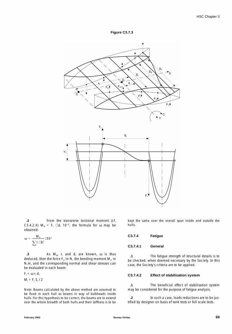
HSC Chapter 3
Figure C3.7.3
.2 From the transverse torsional moment (cf.C3.4.2.4) Mtt = Fi ⋅ di 10−3, the formula for ω may beobtained:
.3 As Mtt, ri and di are known, ω is thusdeduced, then the force Fi, in N, the bending moment Mi, inN.m, and the corresponding normal and shear stresses canbe evaluated in each beam:
Fi = ω ri di
Mi = Fi Si / 2
Note: Beams calculated by the above method are assumed tobe fixed in each hull as beams in way of bulkheads insidehulls. For this hypothesis to be correct, the beams are to extendover the whole breadth of both hulls and their stiffness is to be
kept the same over the overall span inside and outside thehulls.
C3.7.4 Fatigue
C3.7.4.1 General
.1 The fatigue strength of structural details is tobe checked, when deemed necessary by the Society. In thiscase, the Society’s criteria are to be applied.
C3.7.4.2 Effect of stabilisation system
.1 The beneficial effect of stabilisation systemmay be considered for the purpose of fatigue analysis.
.2 In such a case, loads reductions are to be jus-tified by designer on basis of tank tests or full scale tests.
Yi
Fi
Fi
Si
FnFi+1
FiF2
F1
0
X
G
xi
S1S2
Si
di
Y
C
ωMtt
ri di2⋅
--------------------- 103⋅=
February 2002 Bureau Veritas 69
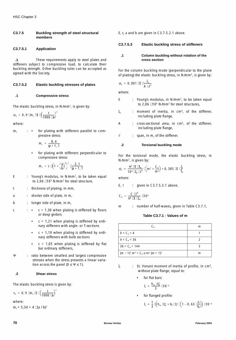
HSC Chapter 3
C3.7.5 Buckling strength of steel structuralmembers
C3.7.5.1 Application
.1 These requirements apply to steel plates andstiffeners subject to compressive load, to calculate theirbuckling strength. Other buckling rules can be accepted asagreed with the Society.
C3.7.5.2 Elastic buckling stresses of plates
.1 Compressive stress
The elastic buckling stress, in N/mm2, is given by:
where:
mc : • for plating with stiffeners parallel to com-pressive stress:
• for plating with stiffeners perpendicular tocompressive stress:
E : Young’s modulus, in N/mm2, to be taken equalto 2,06 ⋅ 105 N/mm2 for steel structure,
t : thickness of plating, in mm,
a : shorter side of plate, in m,
b : longer side of plate, in m,
c : • c = 1,30 when plating is stiffened by floorsor deep girders
• c = 1,21 when plating is stiffened by ordi-nary stiffeners with angle- or T-sections
• c = 1,10 when plating is stiffened by ordi-nary stiffeners with bulb sections
• c = 1,05 when plating is stiffened by flatbar ordinary stiffeners,
Ψ : ratio between smallest and largest compressivestresses when the stress presents a linear varia-tion across the panel (0 ≤ Ψ ≤ 1).
.2 Shear stress
The elastic buckling stress is given by:
where:
mt = 5,34 + 4 ⋅ (a / b)2
E, t, a and b are given in C3.7.5.2.1 above.
C3.7.5.3 Elastic buckling stress of stiffeners
.1 Column buckling without rotation of thecross section
For the column buckling mode (perpendicular to the planeof plating) the elastic buckling stress, in N/mm2, is given by:
where:
E : Young’s modulus, in N/mm2, to be taken equalto 2,06 ⋅ 105 N/mm2 for steel structures,
Ia : moment of inertia, in cm4, of the stiffener,including plate flange,
A : cross-sectional area, in cm2, of the stiffener,including plate flange,
: span, in m, of the stiffener.
.2 Torsional buckling mode
For the torsional mode, the elastic buckling stress, inN/mm2, is given by:
where:
E, : given in C3.7.5.3.1 above,
m : number of half-waves, given in Table C3.7.1,
Table C3.7.1 - Values of m
It : St. Venant moment of inertia of profile, in cm4,without plate flange, equal to:
• for flat bars:
• for flanged profile:
σE 0 9 mc E t1000 a⋅--------------------
2
⋅ ⋅ ⋅,=
mc8 4,
ψ 1 1,+--------------------=
mc c 1ab---
2
+
2 2 1,ψ 1 1,+--------------------⋅ ⋅=
τ E 0 9 mt E t1000 a⋅--------------------
2
⋅ ⋅ ⋅,=
CK m
0 < Ck < 4 1
4 < Ck < 36 2
36 < Ck < 144 3
(m − 1)2 m2 < Ck ≤ m2 (m + 1)2 m
σE 0 001 EIa
A 2⋅
-------------⋅ ⋅,=
σEπ2 E Iw⋅ ⋅
104 Ip 2⋅ ⋅
-------------------------- m2 CK
m2-------+
0 385 E
It
Ip
---⋅ ⋅,+⋅=
CKC
4⋅π4 E Iw⋅ ⋅---------------------- 106⋅=
Ithw tw
3⋅3
--------------- 10 4–⋅=
It13--- hw tw
3 bf tf3 1 0 63
tf
bf
----⋅,– ⋅ ⋅+⋅
10 4–⋅ ⋅=
70 Bureau Veritas February 2002
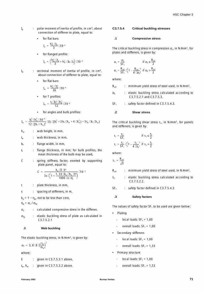
HSC Chapter 3
Ip : polar moment of inertia of profile, in cm4, aboutconnection of stiffener to plate, equal to:
• for flat bars:
• for flanged profile:
Iw : sectional moment of inertia of profile, in cm6,about connection of stiffener to plate, equal to:
• for flat bars:
• for T profiles:
• for angles and bulb profiles:
hw : web height, in mm,
tw : web thickness, in mm,
bf : flange width, in mm,
tf : flange thickness, in mm; for bulb profiles, themean thickness of the bulb may be used,
C : spring stiffness factor, exerted by supportingplate panel, equal to:
t : plate thickness, in mm,
s : spacing of stiffeners, in m,
kp = 1 − ηp, not to be less than zero,
ηp = σa / σEp
σa : calculated compressive stress in the stiffener,
σEp : elastic buckling stress of plate as calculated inC3.7.5.2.1
.3 Web buckling
The elastic buckling stress, in N/mm2, is given by:
where:
E : given in C3.7.5.3.1 above,
tw, hw : given in C3.7.5.3.2 above.
C3.7.5.4 Critical buckling stresses
.1 Compressive stress
The critical buckling stress in compression σc, in N/mm2, forplates and stiffeners, is given by:
where:
ReH : minimum yield stress of steel used, in N/mm2,
σE : elastic buckling stress calculated according toC3.7.5.2.1 and C3.7.5.3.
SF1 : safety factor defined in C3.7.5.4.3.
.2 Shear stress
The critical buckling shear stress τc, in N/mm2, for panelsand stiffeners, is given by:
where:
ReH : minimum yield stress of steel used, in N/mm2,
τE : elastic buckling stress calculated according toC3.7.5.2.2.
SF1 : safety factor defined in C3.7.5.4.3
.3 Safety factors
The values of safety factor SF1 to be used are given below:
• Plating
- local loads: SF1 = 1,00
- overall loads: SF1 = 1,00
• Secondary stiffeners
- local loads: SF1 = 1,00
- overall loads: SF1 = 1,33
• Primary structure
- local loads: SF1 = 1,00
- overall loads: SF1 = 1,53
Iphw
3 tw⋅3
--------------- 10 4–⋅=
Iphw
3 tw⋅3
--------------- hw2 bf tf⋅ ⋅+
10 4–⋅=
Iwhw
3 tw3⋅
36---------------- 10 6–⋅=
Iwtf bf
3 hw2⋅ ⋅
12------------------------ 10 6–⋅=
Iwbf
3 hw2 10 6–⋅ ⋅
12 bf hw+( )2⋅----------------------------------- tf bf
2 2bf hw⋅ 4 hw2⋅+ +( )⋅ 3tw bf hw⋅ ⋅+( )⋅=
Ckp E t3⋅ ⋅
3s 1 1 33 kp hw t3⋅ ⋅ ⋅,1000 s tw
3⋅ ⋅-----------------------------------------+
⋅
-------------------------------------------------------------------- 10 3–⋅=
σE 3 8 Etw
hw
------
2
⋅ ⋅,=
σcσE
SF1
--------= if σEReH
2--------≤
σcReH
SF1
-------- 1 ReH
4 σE⋅-------------–
⋅= if σE
ReH
2-------->
τ cτ E
SF1
--------= if τ Eτ F
2----≤
τ cτ F
SF1
-------- 1 τ F
4 τE⋅------------–
⋅= if τ E
τ F
2---->
τ FReH
3--------=
February 2002 Bureau Veritas 71
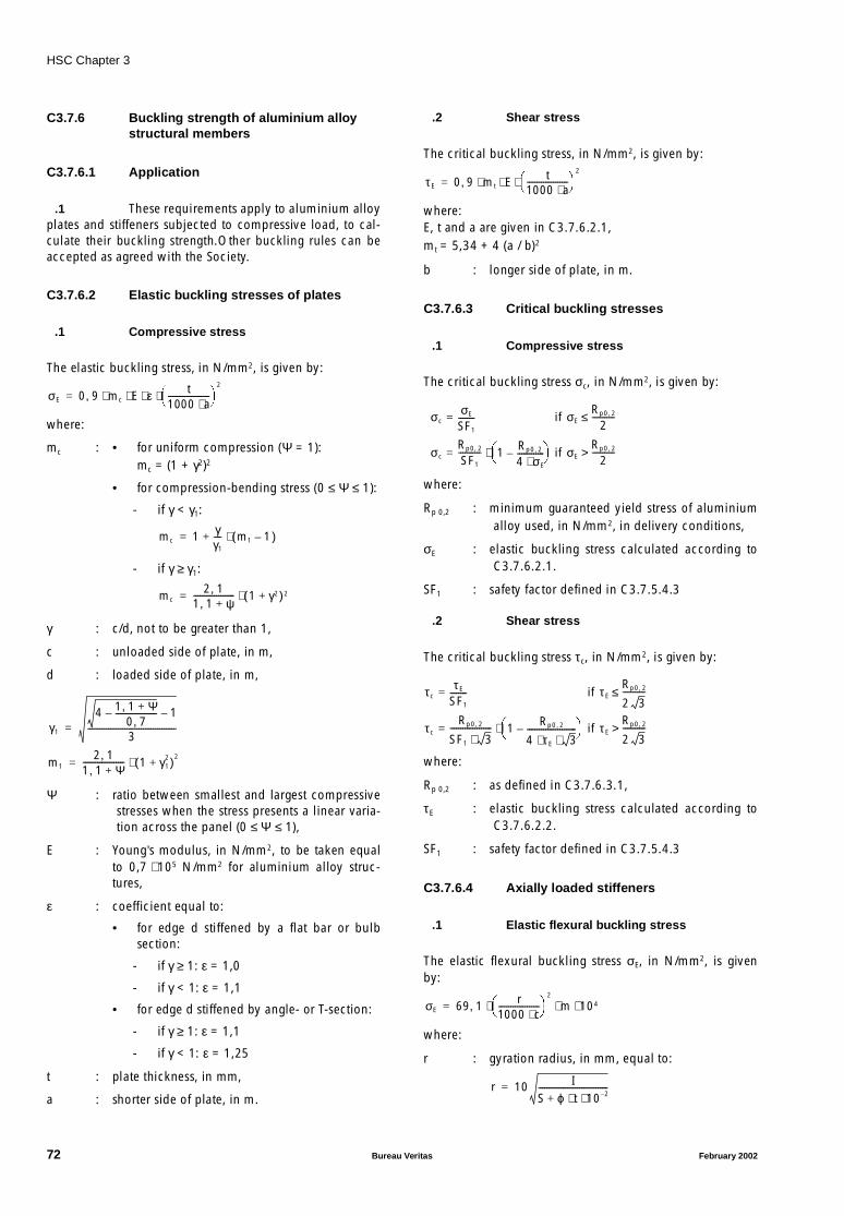
HSC Chapter 3
C3.7.6 Buckling strength of aluminium alloystructural members
C3.7.6.1 Application
.1 These requirements apply to aluminium alloyplates and stiffeners subjected to compressive load, to cal-culate their buckling strength.Other buckling rules can beaccepted as agreed with the Society.
C3.7.6.2 Elastic buckling stresses of plates
.1 Compressive stress
The elastic buckling stress, in N/mm2, is given by:
where:
mc : • for uniform compression (Ψ = 1):mc = (1 + γ2)2
• for compression-bending stress (0 ≤ Ψ ≤ 1):
- if γ < γ1:
- if γ ≥ γ1:
γ : c/d, not to be greater than 1,
c : unloaded side of plate, in m,
d : loaded side of plate, in m,
Ψ : ratio between smallest and largest compressivestresses when the stress presents a linear varia-tion across the panel (0 ≤ Ψ ≤ 1),
E : Young’s modulus, in N/mm2, to be taken equalto 0,7 ⋅ 105 N/mm2 for aluminium alloy struc-tures,
ε : coefficient equal to:
• for edge d stiffened by a flat bar or bulbsection:
- if γ ≥ 1: ε = 1,0
- if γ < 1: ε = 1,1
• for edge d stiffened by angle- or T-section:
- if γ ≥ 1: ε = 1,1
- if γ < 1: ε = 1,25
t : plate thickness, in mm,
a : shorter side of plate, in m.
.2 Shear stress
The critical buckling stress, in N/mm2, is given by:
where:E, t and a are given in C3.7.6.2.1,mt = 5,34 + 4 (a / b)2
b : longer side of plate, in m.
C3.7.6.3 Critical buckling stresses
.1 Compressive stress
The critical buckling stress σc, in N/mm2, is given by:
where:
Rp 0,2 : minimum guaranteed yield stress of aluminiumalloy used, in N/mm2, in delivery conditions,
σE : elastic buckling stress calculated according toC3.7.6.2.1.
SF1 : safety factor defined in C3.7.5.4.3
.2 Shear stress
The critical buckling stress τc, in N/mm2, is given by:
where:
Rp 0,2 : as defined in C3.7.6.3.1,
τE : elastic buckling stress calculated according toC3.7.6.2.2.
SF1 : safety factor defined in C3.7.5.4.3
C3.7.6.4 Axially loaded stiffeners
.1 Elastic flexural buckling stress
The elastic flexural buckling stress σE, in N/mm2, is givenby:
where:
r : gyration radius, in mm, equal to:
σE 0 9 mc E ε t1000 a⋅--------------------
2
⋅ ⋅ ⋅ ⋅,=
mc 1 γγ1
---- m1 1–( )⋅+=
mc2 1,
1 1, ψ+-------------------- 1 γ2+( )2⋅=
γ1
4 1 1, Ψ+0 7,
--------------------– 1–
3-------------------------------------------=
m12 1,
1 1, Ψ+-------------------- 1 γ1
2+( )2⋅=
τ E 0 9 mt E t1000 a⋅--------------------
2
⋅ ⋅ ⋅,=
σcσE
SF1
--------= if σERp0 2,
2-----------≤
σcRp0 2,
SF1
----------- 1 Rp0 2,
4 σE⋅-------------–
⋅= if σE
Rp0 2,
2----------->
τcτ E
SF1
--------= if τ ERp0 2,
2 3-----------≤
τcRp0 2,
SF1 3⋅-------------------- 1 Rp0 2,
4 τ E 3⋅ ⋅------------------------–
⋅= if τ E
Rp0 2,
2 3----------->
σE 69 1 r1000 c⋅--------------------
2
m 104⋅ ⋅ ⋅,=
r 10 IS ϕ t 10 2–⋅ ⋅+----------------------------------=
72 Bureau Veritas February 2002
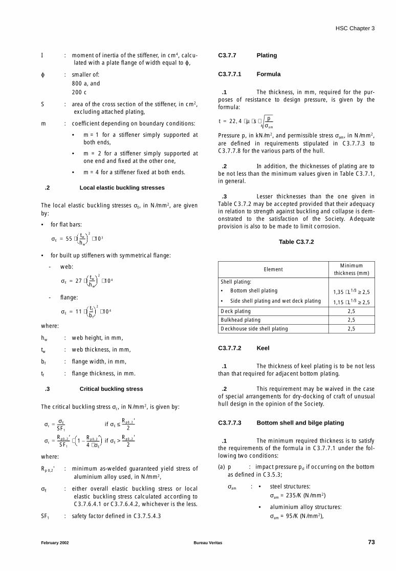
HSC Chapter 3
I : moment of inertia of the stiffener, in cm4, calcu-lated with a plate flange of width equal to ϕ,
ϕ : smaller of:800 a, and200 c
S : area of the cross section of the stiffener, in cm2,excluding attached plating,
m : coefficient depending on boundary conditions:
• m = 1 for a stiffener simply supported atboth ends,
• m = 2 for a stiffener simply supported atone end and fixed at the other one,
• m = 4 for a stiffener fixed at both ends.
.2 Local elastic buckling stresses
The local elastic buckling stresses σE, in N/mm2, are givenby:
• for flat bars:
• for built up stiffeners with symmetrical flange:
- web:
- flange:
where:
hw : web height, in mm,
tw : web thickness, in mm,
bf : flange width, in mm,
tf : flange thickness, in mm.
.3 Critical buckling stress
The critical buckling stress σc, in N/mm2, is given by:
where:
Rp 0,2’ : minimum as-welded guaranteed yield stress ofaluminium alloy used, in N/mm2,
σE : either overall elastic buckling stress or localelastic buckling stress calculated according toC3.7.6.4.1 or C3.7.6.4.2, whichever is the less.
SF1 : safety factor defined in C3.7.5.4.3
C3.7.7 Plating
C3.7.7.1 Formula
.1 The thickness, in mm, required for the pur-poses of resistance to design pressure, is given by theformula:
Pressure p, in kN/m2, and permissible stress σam, in N/mm2,are defined in requirements stipulated in C3.7.7.3 toC3.7.7.8 for the various parts of the hull.
.2 In addition, the thicknesses of plating are tobe not less than the minimum values given in Table C3.7.1,in general.
.3 Lesser thicknesses than the one given inTable C3.7.2 may be accepted provided that their adequacyin relation to strength against buckling and collapse is dem-onstrated to the satisfaction of the Society. Adequateprovision is also to be made to limit corrosion.
Table C3.7.2
C3.7.7.2 Keel
.1 The thickness of keel plating is to be not lessthan that required for adjacent bottom plating.
.2 This requirement may be waived in the caseof special arrangements for dry-docking of craft of unusualhull design in the opinion of the Society.
C3.7.7.3 Bottom shell and bilge plating
.1 The minimum required thickness is to satisfythe requirements of the formula in C3.7.7.1 under the fol-lowing two conditions:
(a) p : impact pressure psl if occurring on the bottomas defined in C3.5.3;
σam : • steel structures:σam = 235/K (N/mm2)
• aluminium alloy structures:σam = 95/K (N/mm2),
σE 55tw
hw
------
2
103⋅ ⋅=
σE 27tw
hw
------
2
104⋅ ⋅=
σE 11tf
bf
----
2
104⋅ ⋅=
σcσE
SF1
--------= if σERp0 2, ′
2-------------≤
σcRp0 2, ′SF1
------------- 1 Rp 0 2, ′4 σE⋅-------------–
⋅= if σE
Rp0 2, ′2
------------->
ElementMinimum
thickness (mm)
Shell plating:
• Bottom shell plating 1,35 ⋅ L1/3 ≥ 2,5
• Side shell plating and wet deck plating 1,15 ⋅ L1/3 ≥ 2,5
Deck plating 2,5
Bulkhead plating 2,5
Deckhouse side shell plating 2,5
t 22 4 µ s pσam
--------⋅ ⋅ ⋅,=
February 2002 Bureau Veritas 73

HSC Chapter 3
(b) p : sea pressure ps as defined in C3.5.5;
σam : • steel structures:
σam = 185/K (N/mm2)
• aluminium alloy structures:
σam = 85/K (N/mm2).
.2 The thickness of bilge plating is not, in anycase, to be less than that of the bottom and side adjacent,whichever is greater.
.3 The thickness of plates connected to thestern frame, or in way of propeller shaft brackets, is to be atleast 1,5 times the thickness of the adjacent plating.
.4 In craft fitted with a bow thruster, the thick-ness of the connection with the housing of such propeller isto be considered individually by the Society.
C3.7.7.4 Sea intakes and other openings
.1 Sea intakes and other openings are to be wellrounded at the corners and located, as far as practicable,well clear of sharp edges.
.2 Sea chests are to have scantlings as forwatertight tank bulkheads (see C3.7.11), taking a designpressure pt, in kN/m2, equal to:
pt = ps + 0,5 ⋅ psl
where ps and psl are as defined in C3.5.5 and C3.5.3respectively.
C3.7.7.5 Plating of side shell and front walls
.1 The minimum required thickness is given bythe formula in C3.7.7.1, assuming:
p : • sea pressure ps as defined in C3.5.5, forside shell plating,
• sea pressure psf as defined in C3.5.6, forfront wall plating,
σam : • steel structures:
σam = 185/K (N/mm2)
• aluminium alloy structures:
σam = 85/K (N/mm2).
If front walls are located at the fore end of the hull, the pres-sure psf (see C3.5.6) and the allowable stresses are to beconsidered individually by the Society.
.2 The thickness of the sheerstrake is to be notless than that of the side or stringer plate.
.3 At the ends of deckhouses, the thickness ofthe sheerstrake is to be suitably increased.
.4 Where side scuttles or windows or otheropenings are located on the sheerstrake, the thickness is tobe increased to compensate for the openings.
C3.7.7.6 Plating of wet deck (cross-deck bottom)and internal sides of catamaran
.1 The minimum required thickness for the wetdeck plating is given by the formula in C3.7.7.1, assuming:
(a) p : impact pressure psl as defined in C3.5.4;
σam : • steel structures:σam = 235/K (N/mm2)
• aluminium alloy structures:σam = 95/K (N/mm2),
(b) p : sea pressure ps as defined in C3.5.5;
σam : • steel structures:σam = 185/K (N/mm2)
• aluminium alloy structures:σam = 85/K (N/mm2).
.2 Moreover, the thickness of internal sides maybe intermediate between that of the bottom of hulls and thebottom of the cross-deck. In any case, it is to be no less thanthat required in C3.7.7.5 for external sides.
C3.7.7.7 Deck plating
.1 The minimum required thickness is given bythe formula in C3.7.7.1, assuming:
p : deck pressure pd as defined in C3.5.8;
σam : • steel structures:σam = 185/K (N/mm2)
• aluminium alloy structures:σam = 85/K (N/mm2).
.2 The thickness, in mm, of decks intended forthe carriage of vehicles is to be not less than the value cal-culated by the formula:t = f ⋅ (c ⋅ P ⋅ K)0,5
where:
f : coefficient equal to:
• 3,9 for steel structures
• 5,6 for aluminium alloy structures,
c : coefficient given in Table C3.7.3 as a functionof the dimensions u and v of the tyre print (seeFigure C3.7.4),
P : static load on the tyre print, in kN, increased by(1 + 0,4 ⋅ av), av being the design vertical accel-eration defined in C3.3.
Where there are double wheels, the tyre print consists ofboth.
74 Bureau Veritas February 2002
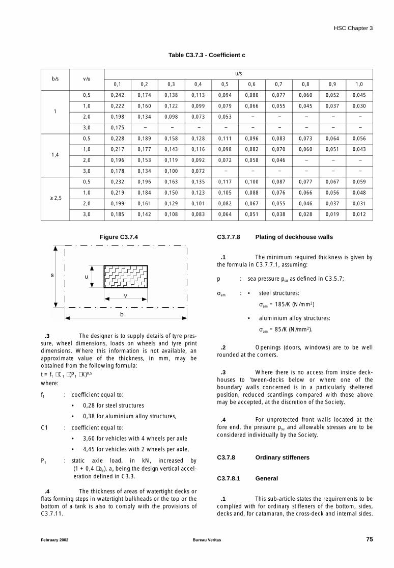
HSC Chapter 3
Table C3.7.3 - Coefficient c
Figure C3.7.4
.3 The designer is to supply details of tyre pres-sure, wheel dimensions, loads on wheels and tyre printdimensions. Where this information is not available, anapproximate value of the thickness, in mm, may beobtained from the following formula:t = f1 ⋅ C1 ⋅ (P1 ⋅ K)0,5
where:
f1 : coefficient equal to:
• 0,28 for steel structures
• 0,38 for aluminium alloy structures,
C1 : coefficient equal to:
• 3,60 for vehicles with 4 wheels per axle
• 4,45 for vehicles with 2 wheels per axle,
P1 : static axle load, in kN, increased by(1 + 0,4 ⋅ av), av being the design vertical accel-eration defined in C3.3.
.4 The thickness of areas of watertight decks orflats forming steps in watertight bulkheads or the top or thebottom of a tank is also to comply with the provisions ofC3.7.11.
C3.7.7.8 Plating of deckhouse walls
.1 The minimum required thickness is given bythe formula in C3.7.7.1, assuming:
p : sea pressure psu as defined in C3.5.7;
σam : • steel structures:
σam = 185/K (N/mm2)
• aluminium alloy structures:
σam = 85/K (N/mm2).
.2 Openings (doors, windows) are to be wellrounded at the corners.
.3 Where there is no access from inside deck-houses to ’tween-decks below or where one of theboundary walls concerned is in a particularly shelteredposition, reduced scantlings compared with those abovemay be accepted, at the discretion of the Society.
.4 For unprotected front walls located at thefore end, the pressure psu and allowable stresses are to beconsidered individually by the Society.
C3.7.8 Ordinary stiffeners
C3.7.8.1 General
.1 This sub-article states the requirements to becomplied with for ordinary stiffeners of the bottom, sides,decks and, for catamaran, the cross-deck and internal sides.
b/s v/uu/s
0,1 0,2 0,3 0,4 0,5 0,6 0,7 0,8 0,9 1,0
1
0,5 0,242 0,174 0,138 0,113 0,094 0,080 0,077 0,060 0,052 0,045
1,0 0,222 0,160 0,122 0,099 0,079 0,066 0,055 0,045 0,037 0,030
2,0 0,198 0,134 0,098 0,073 0,053 − − − − −
3,0 0,175 − − − − − − − − −
1,4
0,5 0,228 0,189 0,158 0,128 0,111 0,096 0,083 0,073 0,064 0,056
1,0 0,217 0,177 0,143 0,116 0,098 0,082 0,070 0,060 0,051 0,043
2,0 0,196 0,153 0,119 0,092 0,072 0,058 0,046 − − −
3,0 0,178 0,134 0,100 0,072 − − − − − −
≥ 2,5
0,5 0,232 0,196 0,163 0,135 0,117 0,100 0,087 0,077 0,067 0,059
1,0 0,219 0,184 0,150 0,123 0,105 0,088 0,076 0,066 0,056 0,048
2,0 0,199 0,161 0,129 0,101 0,082 0,067 0,055 0,046 0,037 0,031
3,0 0,185 0,142 0,108 0,083 0,064 0,051 0,038 0,028 0,019 0,012
s
b
v
u
February 2002 Bureau Veritas 75
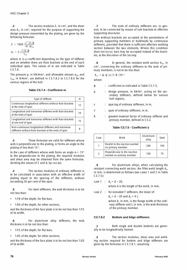
HSC Chapter 3
.2 The section modulus Z, in cm3, and the sheararea At, in cm2, required for the purpose of supporting thedesign pressure transmitted by the plating, are given by thefollowing formulae:
where m is a coefficient depending on the type of stiffenerand on whether there are Rule brackets at the end of eachindividual span. The values of m are indicated in TableC3.7.4.
The pressure p, in kN/mm2, and allowable stresses σam andτam, in N/mm2, are defined in C3.7.8.2 to C3.7.8.6 for thevarious regions of the hull.
Table C3.7.4 - Coefficient m
.3 These formulae are valid for stiffeners whoseweb is perpendicular to the plating, or forms an angle to theplating of less than 15°.
In the case of stiffeners whose web forms an angle α > 15°to the perpendicular to the plating, the required modulusand shear area may be obtained from the same formulae,dividing the values of Z and At by cos (α).
.4 The section modulus of ordinary stiffeners isto be calculated in association with an effective width ofplating equal to the spacing of the stiffeners, withoutexceeding 20 per cent of the span.
.5 For steel stiffeners, the web thickness is to benot less than:
• 1/18 of the depth, for flat bars,
• 1/50 of the depth, for other sections,
and the thickness of the face plate is to be not less than 1/15of its width.
.6 For aluminium alloy stiffeners, the webthickness is to be not less than:
• 1/15 of the depth, for flat bars,
• 1/35 of the depth, for other sections,
and the thickness of the face plate is to be not less than 1/20of its width.
.7 The ends of ordinary stiffeners are, in gen-eral, to be connected by means of rule brackets to effectivesupporting structures.
Ends without brackets are accepted at the penetrations ofprimary supporting members or bulkheads by continuousstiffeners, provided that there is sufficient effective weldingsection between the two elements. Where this conditiondoes not occur, bars may be accepted instead of the brack-ets, at the discretion of the Society.
.8 In general, the resistant weld section Aw, incm2, connecting the ordinary stiffeners to the web of pri-mary members, is not to be less than:
where:
ϕ : coefficient as indicated in Table C3.7.5,
p : design pressure, in kN/m2, acting on the sec-ondary stiffeners, defined below for varioushull regions,
s : spacing of ordinary stiffeners, in m,
: span of ordinary stiffeners, in m,
K : greatest material factor of ordinary stiffener andprimary member, defined in C3.2.
Table C3.7.5 - Coefficient ϕ
.9 For aluminium alloys, when calculating theresistant connecting weld section, the fillet weld length de,in mm, is determined as follows (see cases 1 and 2 in TableC3.7.5):
case 1 : de = d − 20,
where d is the length of the weld, in mm,
case 2 : for extruded T stiffeners, the lesser of:
de = d − 20 and de = 4 t,
where b, in mm, is the flange width of the ordi-nary stiffener and t, in mm, is the web thicknessof the primary member.
C3.7.8.2 Bottom and bilge stiffeners
.1 Both single and double bottoms are gener-ally to be longitudinally framed.
.2 The section modulus, shear area and weld-ing section required for bottom and bilge stiffeners aregiven by the formulae in C3.7.8.1, assuming:
Type of stiffener m
Continuous longitudinal stiffeners without Rule brackets at the ends of span
12
Longitudinal and transverse stiffeners with Rule brackets at the ends of span
19
Longitudinal and transverse stiffeners with Rule brackets at one end of span
15
Non-continuous longitudinal stiffeners and transverse stiffeners without Rule brackets at the ends of span
8
Z 1000
2 s p⋅ ⋅m σam⋅-------------------⋅=
At 5 s p⋅ ⋅
τ am
-----------------⋅=
Case WeldAluminium
alloySteel
1Parallel to the reaction exerted on primary member
200 100
2Perpendicular to the reaction exerted on primary member
160 75
Aw ϕ p s K 10 3–⋅ ⋅ ⋅ ⋅ ⋅=
76 Bureau Veritas February 2002
HSC Chapter 3
(a) p : impact pressure psl if occurring on the bottomas defined in C3.5.3;
σam , τam : • steel structures:σam = 150/K (N/mm2)
τam = 90/K (N/mm2)
• aluminium alloy structures:σam = 70/K (N/mm2)
τam = 45/K (N/mm2),
(b) p : sea pressure ps as defined in C3.5.5;
σam, τam : • stiffeners contributing to the longitudi-nal strength:
- steel structures:σam = 150 CS/K (N/mm2)
τam = 90/K (N/mm2)
- aluminium alloy structures:σam = 70 CA/K (N/mm2)
τam = 45/K (N/mm2),
• stiffeners not contributing to the longi-tudinal strength:
- steel structures:σam = 150/K (N/mm2)
τam = 90/K (N/mm2)
- aluminium alloy structures:σam = 70/K (N/mm2)
τam = 45/K (N/mm2),
where CS and CA are given by Table C3.7.6.
.3 Bottom longitudinals are preferably continu-ous through the transverse elements. Where they areinterrupted at a transverse watertight bulkhead, continuous
brackets are to be positioned through the bulkhead so as toconnect the ends of longitudinals.
C3.7.8.3 Side and front wall stiffeners
.1 The section modulus, shear area and weldingsection are given by the formulae in C3.7.8.1, assuming:
p : • sea pressure ps as defined in C3.5.5, forside stiffeners,
• sea pressure psf as defined in C3.5.6, forfront wall stiffeners,
σam , τam : • side stiffeners contributing to the longitudi-nal strength:
- steel structures:σam = 150 CS/K (N/mm2)τam = 90/K (N/mm2)
- aluminium alloy structures:σam = 70 CA/K (N/mm2)τam = 45/K (N/mm2),
• side stiffeners not contributing to the longi-tudinal strength and front wall stiffeners:
- steel structures:σam = 150/K (N/mm2)τam = 90/K (N/mm2)
- aluminium alloy structures:σam = 70/K (N/mm2)τam = 45/K (N/mm2),
where CS and CA are given by Table C3.7.6.
.2 For unprotected front walls located at thefore end, the pressure psf (see C3.5.6) and allowable stressesare to be considered individually by the Society.
Table C3.7.6 - Coefficients CS and CA
L x/LSteel structures
CS
Aluminium alloy structuresCA
L ≤ 24 m 0 ≤ x/L ≤ 1 1 1
L > 24 m (Note 2) 0 ≤ x/L ≤ 1 1,4 - 1/e 1,3 - 1/e
Alternative method for 24 m < L ≤ 65 m(Note 3)
x/L < 0,1 1 1
0,1 ≤ x/L ≤ 0,3
0,3 < x/L < 0,7
0,7 ≤ x/L ≤ 0,9
0,9 < x/L ≤ 1 1 1
Note 1 : In these formulae, the values of CS and CA are to be taken less than or equal to 1.
Note 2 : The ratio e is to be calculated at the location x, on basis of bending moment distribution defined in C3.4.1and C3.4.2.
Note 3 : The ratio e is to be calculated at the section comprised between 0,3 ⋅ L and 0,7 ⋅ L at which e takes the highest value.
1 0 5 0 4 1e---–,
10 x
L---⋅ 1–
⋅ ⋅,+ 1 0 5 0 3 1
e---–,
10 x
L---⋅ 1–
⋅ ⋅,+
1 4 1e---–, 1 3 1
e---–,
1 0 5,– 0 4, 1e---–
10 x
L---⋅ 9–
⋅ ⋅ 1 0 5,– 0 3, 1
e---–
10 x
L---⋅ 9–
⋅ ⋅
February 2002 Bureau Veritas 77

HSC Chapter 3
C3.7.8.4 Stiffeners of wet deck (cross-deckbottom) and internal sides of catamaran
.1 The section modulus, shear area and weld-ing section required for bottom stiffeners of the cross-deckare given by the formulae in C3.7.8.1, assuming:
(a) p : impact pressure psl as defined in C3.5.4;
σam , τam : • steel structures:σam = 180/K (N/mm2)τam = 90/K (N/mm2)
• aluminium alloy structures:σam = 85/K (N/mm2)τam = 45/K (N/mm2),
(b) p : sea pressure ps as defined in C3.5.5;
σam , τam : • stiffeners contributing to the longitudi-nal strength:
- steel structures:σam = 150 CS/K (N/mm2)τam = 90/K (N/mm2)
- aluminium alloy structures:σam = 70 CA/K (N/mm2)τam = 45/K (N/mm2),
• stiffeners not contributing to the longi-tudinal strength:
- steel structures:σam = 150/K (N/mm2)τam = 90/K (N/mm2)
- aluminium alloy structures:σam = 70/K (N/mm2)τam = 45/K (N/mm2),
where CS and CA are given by Table C3.7.6.
.2 Internal side stiffeners may have characteris-tics intermediate between those of the bottom of the hulland those of the bottom of the cross-deck. In any case, suchcharacteristics are not to be less than those required inC3.7.8.3 for external sides.
C3.7.8.5 Deck stiffeners
.1 The section modulus, shear area and weld-ing section are given by the formulae in C3.7.8.1,assuming:
p : deck pressure pd as defined in C3.5.8,
σam , τam : • stiffeners contributing to the longitudinalstrength:
- steel structures:σam = 150 CS/K (N/mm2)τam = 90/K (N/mm2)
- aluminium alloy structures:σam = 70 CA/K (N/mm2)τam = 45/K (N/mm2),
• stiffeners not contributing to the longitudinalstrength:
- steel structures:σam = 150/K (N/mm2)τam = 90/K (N/mm2)
- aluminium alloy structures:σam = 70/K (N/mm2)τam = 45/K (N/mm2),
where CS and CA are given by Table C3.7.6.
.2 Where there are concentrated loads of signif-icant magnitude, deck stiffeners are to be adequatelystrengthened. In particular, stiffeners of decks intended forthe carriage of vehicles are to be able to support the con-centrated loads transmitted by the wheels, including inertiaeffects.In this case, the structural check is, in general, to be carriedout adopting the static model of the continuous girder onseveral supports (formed by primary supporting members)and considering the most severe vehicle loading arrange-ment for deck stiffeners. The normal and shear stresses thuscalculated are not to exceed the allowable limits definedabove.
.3 The ordinary stiffeners of decks or flats con-stituting the top or bottom of tanks are also to comply withthe requirements of C3.7.11.
.4 Where longitudinals are interrupted in wayof watertight bulkheads or reinforced transverse structures,the continuity of the structure is to be maintained by meansof brackets penetrating the transverse element. The Societymay allow double brackets welded to the transverse ele-ment, provided that special provision is made for thealignment of longitudinals, and full penetration welding isused.
C3.7.8.6 Stiffeners of boundary walls ofdeckhouses
.1 The section modulus, shear area and weld-ing section are given by the formulae in C3.7.8.1,assuming:
p : sea pressure psu as defined in C3.5.7,
σam , τam : • steel structures:σam = 150/K (N/mm2)τam = 90/K (N/mm2),
• aluminium alloy structures:σam = 70/K (N/mm2)τam = 45/K (N/mm2).
.2 If unprotected front walls are located at thefore end, the pressure psu and the allowable stresses are tobe considered individually by the Society.
.3 Any front or side wall vertical stiffeners offirst tier deckhouses are to be connected, by means ofbrackets at the ends, to strengthening structures for decks oradjacent sides.
78 Bureau Veritas February 2002
HSC Chapter 3
.4 Longitudinal stiffeners are to be fitted on theupper and lower edges of large openings in the plating. Theopenings for doors are, in general, to be stiffened all theway round.
.5 Where there is no access from inside deck-houses to ’tween-decks below, or where a deckhouseboundary wall is in a particularly sheltered location,reduced scantlings with respect to those stipulated abovemay be accepted, in the opinion of the Society.
C3.7.9 Primary supporting members
C3.7.9.1 General
.1 This article gives the requirements to becomplied with for primary supporting members of the bot-tom, sides, decks and, for catamaran, the cross-deck.
.2 The primary supporting members (floors,frames, beams) are to form continuous transverse frames. Ingeneral, the stiffened frame spacing, in mm, is not toexceed:1200 + 10 Lwithout being greater than 2 m.Primary supporting members with spacing other than thatdefined above may be required for specific parts of the hull(e.g. machinery space, under pillars), as stipulated in theprovisions below.
.3 The section modulus Z, in cm3, and sheararea At, in cm2, required to support the design pressuretransmitted by the ordinary stiffeners are given by the fol-lowing formulae:
where:
m : coefficient which depends on support condi-tions at the ends of the girder span, generallyassumed to be equal to:
• 10 for floors, bottom girders, side frames,deck beams and girders, vertical webs ofsuperstructures
• 12 for side stringers.
In special circumstances, a different value may be taken form, at the discretion of the Society.
The pressure p, in kN/m2, and allowable stresses σam andτam, in N/mm2, are defined in C3.7.9.2 to C3.7.9.6 for vari-ous parts of the hull.
.4 The above formulae are applicable wherereinforced structures are not of the grillage type. Otherwise,the scantlings of reinforced structures are to be stipulated bymeans of direct calculations performed on the basis of crite-ria agreed upon with the Society.
.5 The section modulus of primary supportingmembers is to be calculated in association with an attachedplating, according to criteria specified by the Society.
.6 For steel stiffeners, the following geometricratios are to be satisfied:
• the web thickness is to be not less than 1/80 of webdepth,
• the face plate thickness is to be not less than 1/30 offace plate breadth (1/15 for face plates which are notsymmetrical with respect to the web).
.7 For aluminium stiffeners, the following geo-metric ratios are to be satisfied, where the compressivestress is not known:
• the web thickness is to be not less than 1/35 of webdepth,
• the face plate thickness is to be not less than 1/20 offace plate breadth (1/10 for face plates which are notsymmetrical with respect to the web).
.8 Particular attention is to be paid to compres-sive buckling strength of associated plating of transverseprimary members
.9 In case of primary structure made of floatingframes and extruded panels, the flexural contribution of theextruded plating may generally be disregarded.
C3.7.9.2 Floors and girders of single bottom
.1 The section modulus and shear area aregiven by the formulae in C3.7.9.1 for the following twoconditions:
(a) p : impact pressure psl if occurring on the bottomas defined in C3.5.3;
σam , τam : • steel structures:σam = 150/K (N/mm2)τam = 90/K (N/mm2)
• aluminium alloy structures:σam = 70/K (N/mm2)τam = 45/K (N/mm2),
(b) p : sea pressure ps as defined in C3.5.5;
σam , τam : • steel floors:σam = 150/K (N/mm2)τam = 90/K (N/mm2)
• aluminium alloy floors:σam = 70/K (N/mm2)τam = 45/K (N/mm2)
• steel girders:σam = 150 CS/K (N/mm2)τam = 90/K (N/mm2)
• aluminium alloy girders:σam = 70 CA/K (N/mm2)τam = 45/K (N/mm2),
where CS and CA are given by Table C3.7.6.
Z 1000 S2 b p⋅ ⋅m σam⋅--------------------⋅=
At 5S b p⋅ ⋅
τ am
------------------⋅=
February 2002 Bureau Veritas 79

HSC Chapter 3
.2 Floors are to be positioned in way of sideand deck transverses. Intermediate floors may also be fittedprovided that they are adequately connected at the ends.
.3 Manholes and other openings are not to belocated at the ends of floor or girder spans, unless shearstress checks are carried out in such areas.
.4 Floors are to be fitted in machinery spaces,generally at every frame, and additional stiffeners are to beprovided at bottom in way of machinery and pillars.
.5 In way of main machinery seatings, girdersare to be positioned extending from the bottom to the foun-dation plate of main engines.
.6 A girder is, generally, to be fitted centrelinefor dry-docking. The height of such a girder is to be not lessthan that of floors amidships and the thickness less than thevalue t, in mm, obtained from the formula:
• for steel:
• for aluminium alloys:
The girder is to be fitted with a continuous face plate abovethe floors, its area not less than the value Ap, in cm2, givenby the formula:
• for steel:
Ap = 0,25 ⋅ L ⋅ K
• for aluminium alloys:
Ap = 0,50 ⋅ L ⋅ KIn hulls with a longitudinally framed bottom and widthB > 8 m, side girders are also to be positioned in such a wayas to divide the floor span into approximately equal parts. Incatamaran, B is to be taken as the width of a single-hull. Thethickness of the web may be assumed to be equal to that ofthe centre girder less 1 mm, and the area of the face platemay be reduced to 60% of that of the centre girder. Whereside girders are intended to support floors, a structuralcheck of their scantlings is to be carried out as deemed nec-essary by the Society.
C3.7.9.3 Primary supporting members of sidesand front walls
.1 The section modulus and shear area aregiven by the formulae in C3.7.9.1, assuming:
p : • sea pressure ps as defined in C3.5.5 for pri-mary members of sides,
• sea pressure psf as defined in C3.5.6 for pri-mary members of front walls,
σam , τam : • steel structures:
σam = 150/K − σa (N/mm2)
τam = 90/K (N/mm2),
• aluminium alloy structures:
σam = 70/K − σa (N/mm2)
τam = 45/K (N/mm2),
σa being the stress induced by the normal force in sidetransverses due to deck loads transmitted by deck beams.
.2 For unprotected front walls located at thefore end, the pressure psf (see C3.5.6) and allowable stressesare to be considered individually by the Society.
C3.7.9.4 Primary supporting members of the wetdeck (cross-deck) and internal sides ofcatamaran
.1 In the most common case of cross-deckstructures constituted by transverse stiffener plates enclosedbetween lower plating and a deck, and connected at theends to reinforced hull structures, the scantlings are deter-mined by transverse strength checks aimed at ensuring anadequate connection between the hulls (see C3.7.4).
.2 Where the cross-deck is formed by multiplestructures, each of the latter is also to be checked for theeffect of local loads, in accordance with the followingprovisions.
.3 The section modulus and shear area requiredfor transverse structures of the cross-deck are given by theformulae in C3.7.9.1, for the following two conditions:
(a) lower structures of the cross-deck:
p : impact pressure psl as defined in C3.5.4
σam , τam : • steel structures:
σam = 180/K (N/mm2)
τam = 90/K (N/mm2)
• aluminium alloy structures:
σam = 85/K (N/mm2)
τam = 45/K (N/mm2),
(b) cross-deck structures supporting decks:
p : sea pressure pd as defined in C3.5.8
σam , τam : • steel structures:
σam = 150/K (N/mm2)
τam = 90/K (N/mm2)
• aluminium alloy structures:
σam = 70/K (N/mm2)
τam = 45/K (N/mm2).
.4 Where the lower structure of the cross-deckalso supports a deck, such a structure is to be checked sepa-rately for conditions (a) and (b) above.
.5 The section modulus and shear area requiredfor side transverses of internal sides are given by the formu-lae in C3.7.9.1 for condition (a) above.
t 0 05 L 2+⋅,( ) K0 5,⋅=
t 0 07 L 2 5,+⋅,( ) K0 5,⋅=
80 Bureau Veritas February 2002

HSC Chapter 3
C3.7.9.5 Primary supporting members of decks
.1 In the absence of concentrated loads trans-mitted to the primary supporting member by pillars or otherprimary supporting members, the section modulus andshear area required for deck transverses and deck girderssupporting longitudinals and beams, respectively, are givenby the formulae in C3.7.9.1, assuming:
p : deck pressure pd as defined in C3.5.8,
σam , τam : • steel deck transverses:σam = 150/K (N/mm2)
τam = 90/K (N/mm2),
• aluminium alloy deck transverses:σam = 70/K (N/mm2)
τam = 45/K (N/mm2),
• steel deck girders:σam = 150 CS/K (N/mm2)
τam = 90/K (N/mm2),
• aluminium alloy deck girders:σam = 70 CA/K (N/mm2)
τam = 45/K (N/mm2),where CS and CA are given by Table C3.7.6.
.2 The primary members of decks or flats con-stituting the top or bottom of tanks are also to comply withthe requirements of C3.7.11.
.3 When there are concentrated loads of signifi-cant magnitude (e.g. transmitted by pillars or other primarymembers or due to the carriage of vehicles), deck girdersare to be adequately strengthened.In this case the structural check is, generally, to be carriedout by using the static model of a beam with partial clamp-ing at its ends (clamping coefficient = 0,30).The allowable stresses stipulated above are to beconsidered.The beam section is to be kept constant over its length.
.4 At the discretion of the Society, calculationsbased on different static models may be accepted, depend-ing on the structural typology adopted.
C3.7.9.6 Primary supporting members ofdeckhouse boundary walls
.1 The section modulus and shear area aregiven by the formulae in C3.7.9.1, assuming:
p : sea pressure psu as defined in C3.5.7,
σam , τam : • steel structures:σam = 150/K (N/mm2)
τam = 90/K (N/mm2),
• aluminium alloy structures:σam = 70/K (N/mm2)
τam = 45/K (N/mm2).
.2 Where there is no access from inside deck-houses to ’tween-decks below or where a deckhouseboundary wall is in a particularly sheltered location,reduced scantlings with respect to those stipulated abovemay be accepted at the discretion of the Society.
.3 For unprotected front walls located at thefore end, the pressure psu and allowable stresses are to beconsidered individually by the Society.
C3.7.10 Pillars
C3.7.10.1 Steel pillars
.1 The minimum area A, in cm2, of the sectionof a pillar, is to be not less than:
• for 0 ≤ λ ≤ 1,5
• for λ > 1,5
where:
λ : slenderness of the pillar, i.e. the ratio betweenthe pillar length, in m, and the minimum radiusof gyration of the pillar cross-section, in cm,
Q : load acting on the pillar, in kN, equal to:Q = APG ⋅ p + QC
APG : area of the deck acting on the pillar, in m2,
p : deck load as defined in C3.5.8,
QC : load from pillars above, if any, or any other con-centrated load acting on the pillar, in kN.
.2 The formula for the calculation of A appliesin the case of solid, tubular or prismatic pillars of normalsteel. Where higher tensile steel is used, the minimum areamay be determined as follows:A’ = A ⋅ (235/ReH) provided λ ≤ 1where:
ReH : yield stress, in N/mm², of the steel considered.
.3 Where possible, each pillar is to be alignedwith another pillar above or below. Stiffeners ensuring effi-cient load distribution are to be fitted at the ends of pillars.Where, in exceptional circumstances, pillars support eccen-tric loads, the scantlings are to be adequately increased towithstand the bending moment due to the eccentricity ofthe load.
.4 Where pillars on the inner bottom are not inway of intersections of floors and girders, partial floors orother structures are to be provided to support the loadtransmitted.
.5 In general, solid or open-section pillars are tobe fitted in tanks; this is compulsory for pillars located inspaces intended for products which may produce explosivegases.
A Q 1 0 75, λ2⋅+( )⋅12
-----------------------------------------------=
A Q λ2⋅10
--------------=
February 2002 Bureau Veritas 81

HSC Chapter 3
.6 Heads and heels of pillars are to be continu-ously welded. The welded connections of stiffeners directlyinvolved in the arrangement of pillars are to be adequatelystiffened where necessary.
.7 The thickness of tubular or closed-sectionpillars is generally to be not less than 1/35 of the nominaldiameter or greater dimension of the section. In no case isthis thickness to be less than 3mm.
.8 The thickness of face plates of built-up pillarsis to be not less than 1/18 of the unsupported span of theface plate.
C3.7.10.2 Pillars made of aluminium alloys
.1 Loads on pillars
Where pillars are aligned, the compressive load Q, in kN, isequal to the sum of loads supported by the pillar consideredand those supported by the pillars located above, multipliedby a weighting factor.
The weighting factor depends on the relative position ofeach pillar with respect to that considered.
This coefficient is equal to:
• 1,0 for the pillar considered,
• 0,9 for the pillar immediately above (first pillar of theline),
• 0,81 = 0,92 for the following pillar (second pillar of theline),
• 0,729 = 0,93 for the third pillar of the line,
• in general, 0,9n for the nth pillar of the line, but not lessthan 0,97 = 0,478.
.2 Critical stress for overall buckling of pillars
For global buckling behaviour of pillars made of aluminiumalloy, the critical stress, σc, in N/mm2, is given by theformula:
where:
Rp 0,2’ : minimum as-welded guaranteed yield stress ofaluminium alloy used, in N/mm2,
C : coefficient as given in Figure C3.7.5, and equalto:
• for alloys without heat treatment:
• for alloys with heat treatment:
: length of pillar, in m,
r : minimum radius of gyration, in cm, of the pillarcross section, equal to:
I : minimum moment of inertia, in cm4, of the pil-lar cross section,
A : area, in cm2, of the pillar cross section,
f : coefficient given in Table C3.7.7 depending onthe conditions of fixing of the pillar.
Table C3.7.7 - Coefficient f
σcRp0 2, ′
0 85, 0 25f ⋅
r--------
⋅,+
--------------------------------------------------- C⋅=
11 λ 1 λ+( )2 0 68 λ⋅,( )–+ +---------------------------------------------------------------------------
11 λ 1 λ+( )2 3 2 λ⋅,( )–+ +------------------------------------------------------------------------
λ Rp 0 2, ′σE
-------------=
σE69 1,f ⋅
r--------
2----------------=
r IA----=
Conditions of fixity
f 0,7 1,0 2,0 1,0 2,0
82 Bureau Veritas February 2002
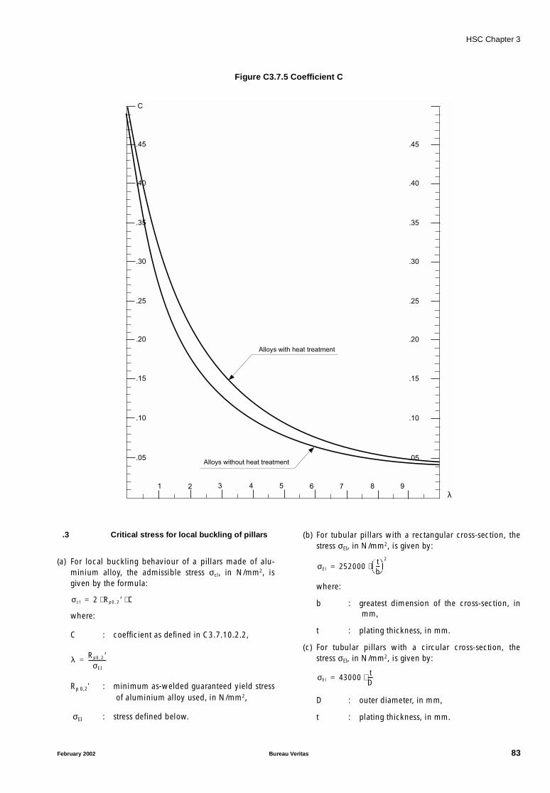
HSC Chapter 3
Figure C3.7.5 Coefficient C
.3 Critical stress for local buckling of pillars
(a) For local buckling behaviour of a pillars made of alu-minium alloy, the admissible stress σcl, in N/mm2, isgiven by the formula:
where:
C : coefficient as defined in C3.7.10.2.2,
Rp 0,2’ : minimum as-welded guaranteed yield stressof aluminium alloy used, in N/mm2,
σEI : stress defined below.
(b) For tubular pillars with a rectangular cross-section, thestress σEI, in N/mm2, is given by:
where:
b : greatest dimension of the cross-section, inmm,
t : plating thickness, in mm.
(c) For tubular pillars with a circular cross-section, thestress σEI, in N/mm2, is given by:
D : outer diameter, in mm,
t : plating thickness, in mm.
.05
.10
.15
.20
.25
.30
.35
.40
.45
C
.05
.10
.15
.20
.25
.30
.35
.40
.45
1 2 3 4 5 6 7 8 9
λ
Alloys with heat treatment
Alloys without heat treatment
σcl 2 Rp0 2, ′ C⋅ ⋅=
λ Rp0 2, ′σEI
-------------=
σEl 252000tb---
2
⋅=
σEl 43000tD----⋅=
February 2002 Bureau Veritas 83
HSC Chapter 3
(d) For pillars with I cross-sections, the stress σEI, in N/mm2,is the lesser of the following values:
where:
tw : web thickness, in mm,
hw : web height, in mm,
tf : thickness of face plate, in mm,
hf : width of face plate, in mm.
.4 Scantlings of pillars
(a) The scantlings of pillars are to comply with the follow-ing requirements:
σ ≤ σc
σ ≤ σcl
where:
σ : compressive stress, in N/mm2, in the pillardue to load Q,
σ = 10 Q/A,
A being the cross-sectional area, in cm2, ofthe pillars,
σc : overall buckling critical stress, as defined inC3.7.10.2.2 above,
σcl : local buckling critical stress, as defined inC3.7.10.2.3 above.
(b) The maximum allowable axial load, in kN, is thesmaller of the following two values:
Pc = σc ⋅ A ⋅ 10 − 1
Pcl = σcl ⋅ A ⋅ 10 − 1
C3.7.11 Tank bulkheads
C3.7.11.1 General
.1 Hollow profiles are not permitted as tankwalls or in tanks for flammable liquids.
C3.7.11.2 Plating
.1 The required thickness, in mm, is given bythe following formula:
where:
fm : coefficient depending on the material:
• fm = 0,80 for steel structures
• fm = 0,75 for aluminium alloy structures,
pt : design pressure, in kN/m2, as defined in C3.5.9,
σam : • steel structures:
σam = 185/K (N/mm2)
• aluminium alloy structures:
σam = 85/K (N/mm2).
C3.7.11.3 Ordinary stiffeners
.1 The section modulus, shear area and weld-ing section required for ordinary stiffeners are given by theformulae in C3.7.8.1, assuming:
p : design pressure pt as defined in C3.5.9,
m : coefficient depending on the type of stiffenerand support conditions at the ends of the stiff-ener span, to be taken according to TableC3.7.4,
σam , τam : • steel structures:
σam = 150/K (N/mm2)
τam = 90/K (N/mm2),
• aluminium alloy structures:
σam = 70/K (N/mm2)
τam = 45/K (N/mm2).
C3.7.11.4 Primary supporting members
.1 The section modulus, shear area and weld-ing section required for horizontal and vertical girders aregiven by the formulae in C3.7.9.1, assuming:
p : design pressure pt as defined in C3.5.9,
m : coefficient depending on support conditions atthe ends of the girder span, generally to betaken equal to 10. A value of 12 could beaccepted if supported by direct calculation,
σam , τam : • steel structures:
σam = 150/K (N/mm2)
τam = 90/K (N/mm2),
• aluminium alloy structures:
σam = 70/K (N/mm2)
τam = 45/K (N/mm2).
C3.7.11.5 Corrugated bulkheads
.1 The thickness and section modulus of corru-gated bulkheads, calculated as stated in C3.7.11.2 toC3.7.11.4 are to be increased by 10% and 20%,respectively.
σEl 252000tw
hw
------
2
⋅=
σEl 105000tf
bf
----
2
⋅=
t 22 4 fm µ s pt
σam
--------⋅ ⋅ ⋅ ⋅,=
84 Bureau Veritas February 2002
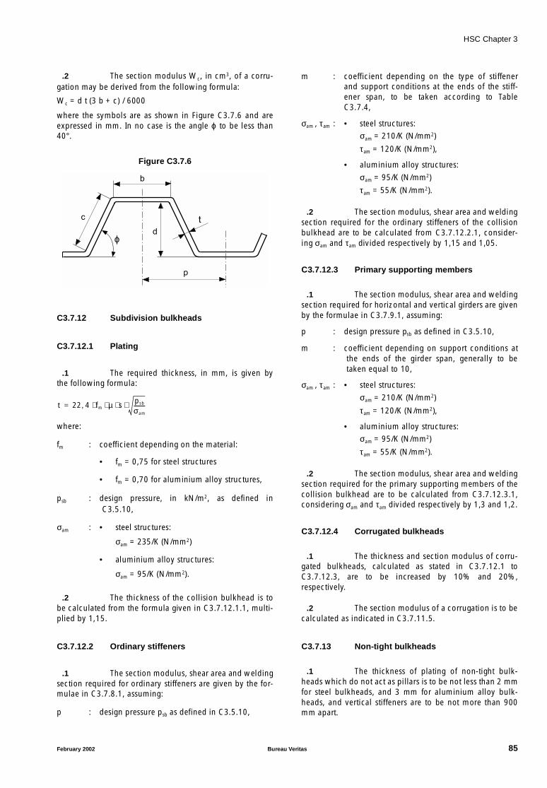
HSC Chapter 3
.2 The section modulus Wc, in cm3, of a corru-gation may be derived from the following formula:
Wc = d t (3 b + c) / 6000
where the symbols are as shown in Figure C3.7.6 and areexpressed in mm. In no case is the angle ϕ to be less than40°.
Figure C3.7.6
C3.7.12 Subdivision bulkheads
C3.7.12.1 Plating
.1 The required thickness, in mm, is given bythe following formula:
where:
fm : coefficient depending on the material:
• fm = 0,75 for steel structures
• fm = 0,70 for aluminium alloy structures,
psb : design pressure, in kN/m2, as defined inC3.5.10,
σam : • steel structures:
σam = 235/K (N/mm2)
• aluminium alloy structures:
σam = 95/K (N/mm2).
.2 The thickness of the collision bulkhead is tobe calculated from the formula given in C3.7.12.1.1, multi-plied by 1,15.
C3.7.12.2 Ordinary stiffeners
.1 The section modulus, shear area and weldingsection required for ordinary stiffeners are given by the for-mulae in C3.7.8.1, assuming:
p : design pressure psb as defined in C3.5.10,
m : coefficient depending on the type of stiffenerand support conditions at the ends of the stiff-ener span, to be taken according to TableC3.7.4,
σam , τam : • steel structures:σam = 210/K (N/mm2)
τam = 120/K (N/mm2),
• aluminium alloy structures:
σam = 95/K (N/mm2)
τam = 55/K (N/mm2).
.2 The section modulus, shear area and weldingsection required for the ordinary stiffeners of the collisionbulkhead are to be calculated from C3.7.12.2.1, consider-ing σam and τam divided respectively by 1,15 and 1,05.
C3.7.12.3 Primary supporting members
.1 The section modulus, shear area and weldingsection required for horizontal and vertical girders are givenby the formulae in C3.7.9.1, assuming:
p : design pressure psb as defined in C3.5.10,
m : coefficient depending on support conditions atthe ends of the girder span, generally to betaken equal to 10,
σam , τam : • steel structures:
σam = 210/K (N/mm2)
τam = 120/K (N/mm2),
• aluminium alloy structures:σam = 95/K (N/mm2)
τam = 55/K (N/mm2).
.2 The section modulus, shear area and weldingsection required for the primary supporting members of thecollision bulkhead are to be calculated from C3.7.12.3.1,considering σam and τam divided respectively by 1,3 and 1,2.
C3.7.12.4 Corrugated bulkheads
.1 The thickness and section modulus of corru-gated bulkheads, calculated as stated in C3.7.12.1 toC3.7.12.3, are to be increased by 10% and 20%,respectively.
.2 The section modulus of a corrugation is to becalculated as indicated in C3.7.11.5.
C3.7.13 Non-tight bulkheads
.1 The thickness of plating of non-tight bulk-heads which do not act as pillars is to be not less than 2 mmfor steel bulkheads, and 3 mm for aluminium alloy bulk-heads, and vertical stiffeners are to be not more than 900mm apart.
b
t
d
c
p
ϕ
t 22 4 fm µ s psb
σam
--------⋅ ⋅ ⋅ ⋅,=
February 2002 Bureau Veritas 85
HSC Chapter 3
.2 Vertical stiffeners of bulkheads which do notact as pillars are to have a section modulus (calculated inassociation with a width of plating equal to the stiffenerspacing but not exceeding 750 mm) not less than the value,in cm3, given by the formula:
Z = 2 s S2
.3 The thickness of plating of non-tight bulk-heads which act as pillars is to be not less than 2 mm forsteel bulkheads, and 3 mm for aluminium alloy bulkheads,and vertical stiffeners are to be not more than 750 mmapart.
.4 Vertical stiffeners of bulkheads which act aspillars are to have a section modulus (calculated in associa-tion with a width of plating equal to the stiffener spacingbut not exceeding 750 mm) not less than the value, in cm3,given by the formula:
Z = 2,65 s S2
.5 In addition, each vertical stiffener, in associa-tion with a width of plating equal to 50 times the platingthickness, is to comply with the requirements for pillarsgiven in C3.7.10, the load supported being determined inaccordance with the same provisions.
.6 In the case of tanks extending from side toside, a wash bulkhead is generally to be fitted amidships;the plating thickness is to be not less than 2 mm for steelbulkheads, and 3 mm for aluminium alloy bulkheads, and itis to be strengthened by vertical stiffeners.
C3.7.14 Independent prismatic tanks
.1 The required thickness for the plating ofindependent prismatic tanks, in mm, is given by theformula:
where:
fm : coefficient depending on the material:
• fm = 1,0 for steel bulkheads
• fm = 1,45 for aluminium alloy bulkheads,
pt : design pressure, in kN/m2, as defined in C3.5.9.
.2 In no case is the thickness to be less than 2,5mm for steel bulkheads, and 3,5 mm for aluminium alloybulkheads.
.3 The section modulus required for stiffeners,in cm3, is given by the formula:
where:
f’m : coefficient depending on the material:
• f’m = 1,0 for steel bulkheads
• f’m = 2,15 for aluminium alloy bulkheads.
.4 The connections to reinforced hull structuresof independent tanks are to be able to withstand thedynamic loads induced by the tank weight and the acceler-ation av of the craft (see C3.3).
.5 It is recommended that stiffener platesshould be arranged so as to prevent undue movement of theliquid.
C3.7.15 Side and stern doors
C3.7.15.1 Plating
.1 The required thickness, in mm, is given bythe following formula:
where:
ps : design pressure, in kN/m2, as defined inC3.5.5.2.1,
σam : • steel structures:
σam = 185/K (N/mm2)
• aluminium alloy structures:
σam = 85/K (N/mm2).
C3.7.15.2 Ordinary stiffeners
.1 The section modulus, shear area and weldingsection required for ordinary stiffeners are given by the for-mulae in C3.7.8.1, assuming:
p : design pressure ps as defined in C3.5.5.2.1,
m : coefficient depending on the type of stiffenerand support conditions at the ends of the stiff-ener span, to be taken according to TableC3.7.4,
σam , τam : • steel structures:
σam = 150/K (N/mm2)
τam = 90/K (N/mm2),
• aluminium alloy structures:
σam = 70/K (N/mm2)
τam = 45/K (N/mm2).
C3.7.15.3 Primary members, securing andsupporting devices
.1 The scantlings of the primary members,securing and supporting devices of side shell doors andstern doors are to be determined to withstand the designloads defined respectively in C3.5.5.2.2 and C3.5.5.2.3,using the following permissible stresses, where k is thematerial factor defined in C3.2.2.3 for steel (not to be takenless than 0,72) or in C3.2.3.5 for aluminium alloys:
t 1 25 fm s µ pt K⋅( )0 5,⋅ ⋅ ⋅ ⋅,=
Z 0 4 f'm s 2 pt K⋅ ⋅ ⋅ ⋅ ⋅,=
t 22 4 µ s ps
σam
--------⋅ ⋅ ⋅,=
86 Bureau Veritas February 2002
HSC Chapter 3
σam : bending stress
• steel structures:σam = 120/K (N/mm2)
• aluminium alloy structures:σam = 55/K (N/mm2),
τam : shear stress
• steel structures:τam = 80/K (N/mm2)
• aluminium alloy structures:τam = 35/K (N/mm2),
σcam :
• steel structures:σam = 150/K (N/mm2)
• aluminium alloy structures:σam = 70/K (N/mm2).
C3.8 Fibre-reinforced plastic craft
C3.8.1 Introduction
.1 This article stipulates requirements for thescantlings of hull structures (plating, stiffeners, primary sup-porting members). The loads acting on such structures areto be calculated in accordance with the provisions of C3.5.
.2 In general, for craft with length L > 65 m orspeed V > 45 knots, the scantlings of transverse structuresare to be verified by direct calculations carried out inaccordance with C3.6.For all other craft, the Society may, at its discretion and asan alternative to the requirements of this article, acceptscantlings for transverse structures of the hull based ondirect calculations, in accordance with C3.6.
C3.8.2 Definitions
.1 In addition to the definitions in C3.1, the fol-lowing is to be considered:
• “Superstructure”: In this article, it is a decked structurelocated above the uppermost continuous deck, extend-ing from side to side of the craft, or with the side platingnot inboard of the shell plating by more than 4 per centof the local breadth.
C3.8.3 Longitudinal strength
C3.8.3.1 General
.1 This article gives the criteria to be used forthe longitudinal strength calculation of monohull shipsmore than 24 m in length.
For multihulls, the strengths due to longitudinal bending,transverse bending and torsion are to be examined individ-ually by the Society.
.2 The longitudinal strength of monohull craftmore than 65 m in length is to be checked.
.3 The longitudinal strength of monohull craftmore than 24 m and less than 65 m in length is to bechecked when the following conditions are not simultane-ously satisfied:
• L/D ≤ r2,
• no longitudinal members located at more than 0,04 Dabove the strength deck at side,
• in any transverse section of strength deck, the sum of thebreadths of openings is less than:
Values of r2 factor are given in Table C3.8.1 depending onthe type of service of the craft.
Table C3.8.1 - Factor r2
.4 In general, the strength deck is the upper-most continuous complete deck or the uppermostsuperstructure deck contributing to the longitudinalstrength, if any.
• The deck number n of a superstructure or a roof with lat-eral sides in line with the shell plating, at least 5 n H inlength and located in the midship region, can be takenas the strength deck in way of the considered transversesections, where:
H : mean height, in m, of the ’tween deck.
• If such a deck is not considered as the strength deck,arrangements are to be made so that this deck does notparticipate in the longitudinal strength of the ship.
• Ships with shell openings such that the length of open-ings is greater than half the length of the shell are to beindividually examined by the Society.
.5 The section moduli at bottom, at the strengthdeck and at the top of longitudinal members located abovethe strength deck, if any, calculated according to C3.8.3.2,are not to be less than the value defined in C3.8.3.3.
C3.8.3.2 Calculation of strength modulus
.1 The data given in Table C3.8.2 for platingand C3.8.3 for longitudinals are necessary for calculation ofthe midship section modulus.
σcam σ2 3 τ2⋅+=
Type of service r2
Open seaRestricted open sea
16,5
Moderate environment 18,0
Smooth sea 22,0
b65 L–
40--------------- B⋅=
February 2002 Bureau Veritas 87

HSC Chapter 3
Table C3.8.2
Table C3.8.3
.2 Where there is a sandwich member, the twoskins of the laminate are to be taken into account only withtheir own characteristics. The cores are taken into account ifthey offer longitudinal continuity and appreciable strengthagainst axial tension-compression.
.3 For each transverse section within the mid-ship region, the section modulus, in m3, is given by:
where:
See also Figure C3.8.1.
C3.8.3.3 Rule section modulus
.1 The midship section modulus at the strengthdeck, at the bottom and above the strength deck, if any, isnot to be less, in m3, than:
where:
r1 : value given in Table C3.8.4,
r2 : value given in Table C3.8.1.
Figure C3.8.1
Table C3.8.4 - Factor r1
C3.8.3.4 Bending longitudinal stress
.1 The bending stress, in N/mm2, due to the lon-gitudinal bending moment is given by the formula:
where Mbl is the total bending moment, defined in C3.4.1,and W is the actual value of the midship section modulus,in m3, either at bottom or at the deck.
C3.8.4 Structural scantling - general
C3.8.4.1 Main principles
.1 Scantlings are given for the midship regionand end regions. In intermediate regions, scantlings are tovary gradually from the midship region to the end regions.
.2 Plating and stiffener scantlings are deter-mined by the fact that the sum of stress due to local designload and longitudinal bending of the hull (if applicable) isto be less than the corresponding allowable stress of thematerial, i.e. the breaking strength divided by a safety fac-tor, defined below.
Deck Side shell Bottom
Mean thickness, in mm tp tm tf
Young modulus, in N/mm2 Ep Em Ef
DeckSide shell
(1 side)Bottom
Flange
Thickness (mm) tps tms tfs
Young modulus (N/mm2)
Eps Ems Efs
Breadth (mm) lps lms lfs
Web
Thickness equivalent to I section (mm)
tpa tma tfa
Young modulus (N/mm2)
Epa Ema Efa
Height (m) Hpa Hma Hfa
Number oflongitudinals
np nm nf
W 1Ep
----- C' P C'6----- A 1 F P–
F 0 5 A⋅,+---------------------------+
⋅ ⋅+⋅
10 3–⋅ ⋅=
P tp B Ep np tps Ips Eps tpa Hpa Epa⋅ ⋅+⋅ ⋅( )⋅+⋅ ⋅=
A 2 tm Im Em nm tms Ims Ems tma Hma Ema⋅ ⋅+⋅ ⋅( )⋅+⋅ ⋅( )⋅=
F tfB2--- Ef nf tfs Ifs Efs t fa Hfa Efa⋅ ⋅+⋅ ⋅( )⋅+⋅ ⋅=
Wm 11 α r1 F L2 B CB 0 7,+( ) 10 6–⋅ ⋅ ⋅ ⋅ ⋅ ⋅ ⋅=
α Lr2 D--------- but not less than 1=
F 118 0 36 L⋅,–( ) L1000-------------=
Type of service r1
Open seaRestricted open sea
1,0
Moderate environment 0,96
Smooth sea 0,92
B/2
B/4
C' l m
M
D
A
σblMb l
W-------- 10 3–⋅=
88 Bureau Veritas February 2002
HSC Chapter 3
.3 Scantlings may be increased where the struc-ture is likely to be subjected to particular forces, forinstance due to:
• very high speed,
• nature or uneven distribution of its loading, such as con-centrated loads,
• particular conditions of operation, construction ordesign.
.4 When design assumptions not covered bythe present Rules or unusual structural arrangements areprovided, the proposed scantlings are to be backed bydirect calculations carried out with an agreed method, andsubmitted to the Society for examination.If so, the shipyard is to provide, to the satisfaction of theSociety, all information needed to verify the calculation.The owner’s agreement may be required where the Societydeems it appropriate.
.5 In addition to the cases explicitly foreseen bythese Rules, subject to justifications submitted for examina-tion, the Society may consider scantlings and structuralarrangement, other than those derived from the applicationof these Rules, in order to take special account of:
• calculation method or a method for the determinationof stresses offering a high level of accuracy; calculationdata and all information necessary for their assessmentare to be submitted to the Society,
• development of the applied techniques, the builder’spractical experience and the means he brings into use toensure an appropriate level of quality and buildingconsistency,
• satisfactory behaviour in service of the type of hullstructure concerned,
• particular loading cases.
.6 Bottom - side shell boundary forcatamarans
For the structure of a catamaran, the inner walls of whichare nearly vertical, the limit between bottom and side shellinside the two hulls is to be taken at the level of chine forexternal walls, as defined in C3.1.4.
C3.8.4.2 Safety factors
.1 The safety factor SF is equal to the ratiobetween the breaking strength (bending or shear) and theallowable stress for a material.
.2 The safety factor to be considered for allowa-ble bending stresses of platings and stiffeners is given inTable C3.8.5.
Table C3.8.5 - Safety factor SF
.3 The safety factor to be considered for allowa-ble shear stress of core material of sandwiches and of webprimary stiffener is given in Table C3.8.6.
Table C3.8.6 - Safety factor SF
.4 For ships of unusual construction and/or withspecial service conditions, another value of the safety factorcan be defined in accordance with the yard, which is to jus-tify the new safety factor.
C3.8.4.3 Single skin laminates
.1 The bending stress, in N/mm2, of the lami-nate is to be multiplied by the following reduction factor ks:ks = µ1 α rc
2
where:
α and rc are defined respectively in C3.8.4.3.2 andC3.8.4.3.3.
SF
General 6,0
Members subject to impact load 4,5
Watertight transverse bulkheads 5,0
Sides and ends of superstructures and deckhouses
4,0
Members subjected to the testing pressure pe
4,0
SF
Core of sandwich
General 3,0
Sandwiches subjected to impact load 2,5
Web ofprimary
members
General 5,0
Stiffeners subject to impact load 3,5
Stiffeners on watertight transverse bulk-head
4,0
Stiffeners of sides and ends of superstruc-tures and deckhouses
3,0
Stiffeners calculated with the testing pressure pe
3,0
µ1 1= if 2s≥
µ1 1 1 5 1
2 s⋅----------–
2
⋅,–= if s 2s< <
µ1 0 625,= if s≤
February 2002 Bureau Veritas 89
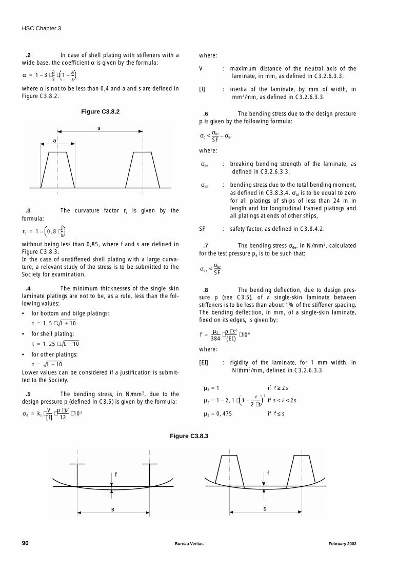
HSC Chapter 3
.2 In case of shell plating with stiffeners with awide base, the coefficient α is given by the formula:
where α is not to be less than 0,4 and a and s are defined inFigure C3.8.2.
Figure C3.8.2
.3 The curvature factor rc is given by theformula:
without being less than 0,85, where f and s are defined inFigure C3.8.3.In the case of unstiffened shell plating with a large curva-ture, a relevant study of the stress is to be submitted to theSociety for examination.
.4 The minimum thicknesses of the single skinlaminate platings are not to be, as a rule, less than the fol-lowing values:
• for bottom and bilge platings:
• for shell plating:
• for other platings:
Lower values can be considered if a justification is submit-ted to the Society.
.5 The bending stress, in N/mm2, due to thedesign pressure p (defined in C3.5) is given by the formula:
where:
V : maximum distance of the neutral axis of thelaminate, in mm, as defined in C3.2.6.3.3,
[I] : inertia of the laminate, by mm of width, inmm4/mm, as defined in C3.2.6.3.3.
.6 The bending stress due to the design pressurep is given by the following formula:
where:
σbr : breaking bending strength of the laminate, asdefined in C3.2.6.3.3,
σbl : bending stress due to the total bending moment,as defined in C3.8.3.4. σbl is to be equal to zerofor all platings of ships of less than 24 m inlength and for longitudinal framed platings andall platings at ends of other ships,
SF : safety factor, as defined in C3.8.4.2.
.7 The bending stress σde, in N/mm2, calculatedfor the test pressure pe is to be such that:
.8 The bending deflection, due to design pres-sure p (see C3.5), of a single-skin laminate betweenstiffeners is to be less than about 1% of the stiffener spacing.The bending deflection, in mm, of a single-skin laminate,fixed on its edges, is given by:
where:
[EI] : rigidity of the laminate, for 1 mm width, inN⋅mm2/mm, defined in C3.2.6.3.3
Figure C3.8.3
α 1 3 as--- 1 a
s---–
⋅ ⋅–=
a
s
rc 1 0 8fs--⋅,
–=
t 1 5 L 10+⋅,=
t 1 25, L 10+⋅=
t L 10+=
σd ksVI[ ]
------ p s2⋅12
------------ 103⋅ ⋅ ⋅=
σdσbr
SF------- σbl–<
σdeσbr
SF-------<
fµ2
384---------- p s4⋅
EI( )------------ 109⋅ ⋅=
µ2 1= if 2s≥
µ2 1 2 1 1
2 s⋅----------–
2
⋅,–= if s 2s< <
µ2 0 475,= if s≤
ss
f f
90 Bureau Veritas February 2002

HSC Chapter 3
C3.8.4.4 Sandwich laminates
.1 Refer to C3.8.4.3.1 to C3.8.4.3.3.
.2 The minimum thicknesses of each skin ofsandwich laminate platings are in general not to be lessthan the following values:
• for bottom and bilge platings:
• for shell plating:
• for other platings:
Lower values can be considered if a justification is submit-ted to the Society.
.3 The bending stress, in N/mm2, due to thedesign pressure p (defined in C3.5) is equal to:
where:
V : maximum distance of the neutral axis of thesandwich, in mm, as defined in C3.2.6.3.3,
[I] : inertia of the sandwich, by mm of width, inmm4/mm, as defined in C3.2.6.3.3.
.4 The bending stress due to the design pressurep is to be such that:
where:
σbr : breaking bending strength of the sandwich, asdefined in C3.2.6.3.4,
σbl : bending stress due to the total bending moment,as defined in C3.8.3.4. σbl is to be equal to zerofor all platings of ships of less than 24 m inlength and for longitudinal framed platings andall platings at ends of other ships,
SF : safety factor, as defined in C3.8.4.2.
.5 The bending stress σde, in N/mm2, calculatedfor the test pressure pe is to be such that:
.6 The shear stress, in N/mm2, due to the designpressure p is to be:
where ta is the thickness of the core, in mm.
.7 The shear stress due to the design pressure isto be such that:
where:
τbr : shear breaking strength of the core material, inN/mm2,
SF : safety factor, as defined in C3.8.4.2.
.8 The sum of the bending and shear deflec-tions, due to the design pressure p (see C3.5), of a sandwichlaminate between stiffeners is to be less than about 1% ofthe stiffener spacing. The total deflection, in mm, of a sand-wich laminate, fixed on its edges, is given by the formula:
where:
[EI] : rigidity of the sandwich laminate, for 1 mmwidth, in N ⋅ mm2/mm, as defined inC3.2.6.3.3,
ta : core thickness, in mm,
G : shear modulus of the core material, in N/mm2,
µ2 : coefficient defined in C3.8.4.3.8,
C3.8.4.5 Stiffeners
.1 The Rule values of stiffener stresses takeaccount of the width lb of the attached plating, definedbelow:
• for primary stiffeners, lb is the smaller of the two values:
- I stiffener: s or 0,2
- Ω stiffener: s or (0,2 + a),where a is defined in C3.8.4.3.2,
• for ordinary stiffeners, lb is equal to the spacing sbetween stiffeners.
.2 To take account of the actual conditions offixation of a stiffener, the following coefficient ε is consid-ered in the scantling formulae:
• if the stiffener is fixed at its ends: ε = 1,0
• in the other cases: ε = 1,5.
.3 Cut-outs for the passage of ordinary stiffenersare to be as small as possible. As a rule, the depth of cut-outs is not to be greater than half the web height of the pri-mary stiffener.
.4 The bending stress, in N/mm2, due to thedesign pressure p (defined in C3.5) is given by the formula:
where:
V : distance from the stiffener neutral axis to theflange, in mm, as defined in C3.2.6.3.5,
[I] : inertia of the stiffener, in mm4, as defined inC3.2.6.3.5.
t 0 6 L 10+⋅,=
t 0 5 L 10+⋅,=
t 0 4 L 10+⋅,=
σd ksVI[ ]
------ p s2⋅12
------------ 103⋅ ⋅ ⋅=
σdσbr
SF------- σbl–<
σdeσbr
SF-------<
τdp s⋅2 ta⋅-----------=
τdτbr
SF------<
fµ2
384---------- p s4⋅
EI[ ]------------ 109 µ3
8----- p s2⋅
ta G⋅------------ 103⋅ ⋅+⋅ ⋅=
µ3 1= if 2s≥
µ3 1 1 8 1
2 s⋅----------–
2
⋅,–= if s 2s< <
µ3 0 550,= if s≤
σd ε p s 2⋅ ⋅12
------------------- VI[ ]
------ 106⋅ ⋅ ⋅=
February 2002 Bureau Veritas 91
HSC Chapter 3
.5 The bending stress due to the design pressureis to be such that:
where:
σbr : breaking bending strength of the stiffener, asdefined in C3.2.6.3.5,
σbl : bending stress due to the total bending moment,as defined in C3.8.3.4. σbl is to be equal to zerofor all stiffeners of ships of less than 24 m inlength and for stiffeners not contributing to thelongitudinal strength and all stiffeners at ends,for other ships,
SF : safety factor, as defined in C3.8.4.2.
.6 The shear stress, in N/mm2, due to the designpressure p (defined in C3.5) is given by the formula:
where Sa is the total web cross-sectional area, in mm2.
.7 For primary stiffeners, the shear stress due tothe design pressure is to be:
where:
τbr : shear breaking strength, in N/mm2, of the lami-nate being the web of the primary stiffener. If aprecise value of τbr obtained from tests or otheragreed method is not available, τbr is to betaken equal to 60 N/mm2,
SF : safety factor, as defined in C3.8.4.2.
.8 The bending stress σde, in N/mm2, calculatedfor the testing pressure pe is to be such that:
.9 For primary stiffeners, the shear stress τde, inN/mm2, calculated for the testing pressure pe is to be:
C3.8.5 Bottom structure
C3.8.5.1 Application
.1 The requirements of C3.8.5 apply to single ordouble-bottom structures with longitudinal or transverseframing.
.2 The requirements of C3.5.8 are to be usedfor the scantlings of the main structural members locatedbetween the keel and the chine, as defined in C3.1.4. Referalso to C3.8.4.1.6 for catamarans.
.3 The requirements of C3.5.8 apply also tostructural members of the cross-deck of catamarans.
C3.8.5.2 General arrangements
.1 In general, a continuous centreline girder isto be provided over the full length of the ship.
.2 In the engine room, additional girders are tobe fitted in order to provide a sufficient structural strength.Unless otherwise specified, the shipyard is to submit thesupporting structure to the engine builder for agreement onrigidity and arrangements.
.3 Floors are to be continuous between the cen-treline keelson and the bilge.
.4 A floor or a girder is to be provided undereach line of pillars.
.5 Main engines and thrust blocks are to besecured to the hull structure by seatings with adequatestrength to withstand forces transmitted by the propulsiveinstallation.
.6 When solid ballast is fitted, it is to besecurely positioned. If necessary, intermediate floors maybe fitted for the purpose.
.7 For each member of web of floor or keelson,the height thickness ratio is not to exceed 25.
.8 Provision is to be made for the free passageof water from all parts of the bottom to the suctions, takinginto account the pumping rate required.
C3.8.5.3 Plating scantlings
.1 Plating scantlings are to be calculated inaccordance with C3.8.4.3 and C3.8.4.4.
.2 The width of the keel plate, in m, is not to beless than (0,6 + 0,01 L).
C3.8.5.4 Stiffener scantlings
.1 Stiffener scantlings are to be calculated inaccordance with C3.8.4.5.
.2 For the scantlings of a bottom girder, its span is to be measured:
• between transverse bulkheads, if the keelson can beconsidered as a support, i.e. if its height is at least 1,5times the height of the floors in the centreline, and itsmoment at least twice the moment of the floors in thecentreline,
• between floors, if the keelson is intercostal, its heightnot exceeding the floor height.
σdσbr
SF------- σbl–<
τdp s ⋅ ⋅2 Sa⋅
-----------------103=
τdτbr
SF------<
σdeσbr
SF-------<
τdeτbr
SF------<
92 Bureau Veritas February 2002

HSC Chapter 3
.3 For the scantlings of a floor, its span is to bemeasured:
• between side shell platings, if the bottom is flat and sup-porting bottom girders or longitudinal bulkheads do notexist,
• between side shell plating and keel, if an important keelexists and supporting bottom girders or longitudinalsbulkheads do not exist,
• between side shell plating and keelson, side shell plat-ing and bulkhead, or bulkhead and bulkhead, iflongitudinal bulkheads or keelson exist, the scantlingsand the span of which are such that they can be consid-ered as a support.
.4 For ships with a rising of floors, the floorspan is to be measured from the ship centreline, when theangle of the rising of floor is greater than:
• 20° in case of built-in floor at side,
• 10° in case of supported floor at side.This being so, the floor bending stress is to be calculated inaccordance with C3.8.4.5, with ε = 1,1.
.5 When the primary structure is made of aframe of crossed stiffeners with equivalent scantlings, a cal-culation of the totality of the stiffeners, taking relativestiffnesses into account, is to be submitted.
C3.8.5.5 Single-bottom structure
.1 Side girders are to be fitted. In general, theirspacing is not to exceed 2,5 m.
.2 Centre and side girders are to be extended asfar aft and forward as practicable.
.3 Where side girders are fitted in lieu of thecentre girder, overlap is to be adequately extended, andadditional stiffening of the centre bottom may be required.
.4 Flanges of bottom girders and floors are to beconnected.
.5 For ships more than 40 m in length withtransverse framed bottom, longitudinal stiffeners connectedto floors are to be fitted between bottom girders, within themidship region. The mean spacing of longitudinal membersis not to exceed 1,4 m.
C3.8.5.6 Double-bottom structure
.1 In general, the height of the double bottom isnot to be less than:
.2 Side girders are to be fitted. In general, theirspacing is not to exceed 4,2 m.
.3 See also C3.8.5.5 above.
C3.8.6 Side shell structure
C3.8.6.1 Application
.1 The requirements of this sub-article apply totransversely or longitudinally framed side shell structure.
.2 The requirements of this sub-article are to beused for the scantlings of the main structural memberslocated between the chine, as defined in C3.1.4, and thehighest continuous deck.
.3 The requirements of this sub-article apply tostructural members of inner walls of catamarans (seeC3.8.4.1.6).
C3.8.6.2 General arrangements
.1 In case of longitudinal framing, the webframes are to be located in way of floors.
.2 In case of transverse framing, the sectionmodulus of the web frames located in the engine room isnot to be less than 4 times that of adjacent frames, and thecross-sectional area of these web frames is not to be lessthan twice that of adjacent frames.
.3 In case of transverse framing, frames are tobe fitted at each frame. The scantlings of main and ’tweendeck frames are not to be less than those of frames locatedimmediately above.
.4 In general, stringers are required if the spanof main and ’tween deck frames is greater than 4 m.
.5 Web frames are to be fitted in way of beamsat hatch ends.
.6 The flanges of stringers and web frames areto be connected if necessary.
C3.8.6.3 Plating scantlings
.1 Plating scantlings are to be calculated inaccordance with C3.8.4.3 and C3.8.4.4.
.2 The width of the sheerstrake, in m, is not tobe less than:
.3 Unless otherwise specified, the thickness ofthe sheerstrake is not to be less than that of the adjacentside shell plating.
.4 The thickness of the sheerstrake is to beincreased by 40% in way of breaks in long superstructuresoccurring within the midship 0,5 L, over a length of aboutone sixth of the ship breadth on each side of the superstruc-ture end.
0 1 L⋅,
b 0 715 0 425 L100----------⋅,+,=
February 2002 Bureau Veritas 93
HSC Chapter 3
.5 The thickness of the sheerstrake is to beincreased by 30% in way of breaks in long superstructuresoccurring outside the midship 0,5 L, over a length of aboutone sixth of the ship breadth on each side of the superstruc-ture end.
.6 The thickness of the sheerstrake is to beincreased by 15% in way of breaks in short superstructuresoccurring within the midship 0,6 L, over a length of aboutone sixth of the ship breadth on each side of the superstruc-ture end.
C3.8.6.4 Stiffener scantlings
.1 Stiffeners scantlings are to be calculated inaccordance with C3.8.4.5.
.2 For the scantlings of a stringer, its span is tobe measured:
• between transverse bulkheads if the stringer can be con-sidered as a support or if there is no vertical web,
• between vertical webs if the stringer is intercostal andcannot be considered as a support between transversebulkheads.
.3 For the scantlings of a vertical web frame, itsspan is to be measured:
• between decks or between deck and bottom, if there areno stringers or if stringers are intercostal,
• between deck and stringer, bottom and stringer orbetween stringers if stringers can be considered as asupport between transverse bulkheads.
.4 When the primary structure is made of aframe of crossed stiffeners with equivalent scantlings, a cal-culation of the totality of stiffeners, taking relative stiffnessesinto account, is to be submitted.
C3.8.7 Deck structure
C3.8.7.1 Application
.1 The requirements of this sub-article apply totransversely or longitudinally framed deck structure.
.2 The requirements of this sub-article are to beused for the scantlings of the main structural members ofthe strength deck, lower and platform decks, accommoda-tion decks and the decks of superstructures and deckhouses.
C3.8.7.2 General arrangements
.1 In case of longitudinal framing, the beamsare to be located in way of the vertical web frames of sideshell.
.2 In case of transverse framing, the beams areto be, in general, fitted at every frame, in line with side shellstiffeners.
.3 In case of vertical break for the strength deck,the continuity of strength is to be ensured by a taperedstructure of the two decks within a length equal to 2 to 5frame spacing.
.4 The transverse strength of ships with largedeck openings is to be individually considered.
.5 In the area of openings, the continuity ofstrength of longitudinal hatch coamings is to be ensured byunderdeck girders.
.6 Hatch girders and reinforced beams are to befitted in way of hatch openings.
.7 The flanges of girders and reinforced beamsare to be connected, if necessary.
.8 In case of concentrated loads on decks (e.g.pillars, winches, davits), direct calculations are to be carriedout taking account of simultaneous design pressure andconcentrated loads.
C3.8.7.3 Plating scantlings
.1 Plating scantlings are to be calculated inaccordance with C3.8.4.3 and C3.8.4.4.
.2 The width of the stringer plate, in m, is not tobe less than:b = 0,005 (L + 70)
.3 Unless otherwise specified, the thickness ofthe stringer plate is not to be less than that of the adjacentplating.
.4 The thickness of the stringer plate is to beincreased by 40% in way of breaks of long superstructuresoccurring within the midship 0,5 L, over a length of aboutone sixth of the ship breadth on each side of the superstruc-ture end.
.5 The thickness of the stringer plate is to beincreased by 30% in way of breaks of long superstructuresoccurring outside the midship 0,5 L, over a length of aboutone sixth of the ship breadth on each side of the superstruc-ture end.
.6 The thickness of the stringer plate is to beincreased by 15% in way of breaks of short superstructuresoccurring within the midship 0,6 L, over a length of aboutone sixth of the ship breadth on each side of the superstruc-ture end.
94 Bureau Veritas February 2002
HSC Chapter 3
C3.8.7.4 Stiffener scantlings
.1 Stiffener scantlings are to be calculated inaccordance with C3.8.4.5.
.2 For the scantlings of a girder, its span l is tobe measured:
• between transverse bulkheads, if the girder can be con-sidered as a support, i.e. if its height is at least 1,5 timesthe height of the floors in the centreline, and its momentat least twice the moment of the floors in the centreline,
• between deck beams, if the girder is intercostal andused to prevent tripping instability of deck beams.
.3 For the scantlings of a deck beam, its span lis to be measured:
• between side shell platings, if there are no girders whichcan be considered as a support or if there are no longi-tudinal bulkheads,
• between side shell plating and bulkhead, side shell plat-ing and girder, between bulkheads or girders if there arelongitudinal bulkheads or girders, the scantlings andspan of which are such that they can be considered as asupport.
.4 Hatch beams and hatch girders are to be ofreinforced scantlings, to take the interrupted stiffeners intoaccount.
.5 The scantlings of hatch beams and girders isnot to be less than those obtained in accordance withC3.8.4.5, changing s to take into account the effective sup-ported areas.
.6 When the primary structure is made of aframe of crossed stiffeners with equivalent scantlings, a cal-culation of the totality of the stiffeners, taking relativestiffnesses into account, is to be submitted.
C3.8.7.5 Deck covers
.1 The scantlings of deck cover platings are tobe determined in accordance with C3.8.4.3 and C3.8.4.4.
.2 The scantlings of the deck cover stiffeners areto be calculated in accordance with C3.8.4.5, the span l ofthe stiffener being measured:
• between the two edges of the cover, if the stiffener canbe considered as a support for this dimension,
• between perpendicular stiffeners, if the stiffener is con-sidered as intercostal.
.3 In case of deck cover with a frame of crossedstiffeners with equivalent scantlings, a calculation of thetotality of the stiffeners, taking into account the relative stiff-nesses, is to be submitted.
C3.8.8 Bulkhead structure
C3.8.8.1 Application
.1 The requirements of this sub-article are to beused for the scantlings of the main structural members of:
• watertight transverse or longitudinal bulkheads,
• transverse or longitudinal tank bulkheads,
• wash transverse or longitudinal bulkheads,
• cofferdam bulkheads,
• shaft tunnel bulkheads.
C3.8.8.2 General arrangements
.1 The scantlings of tank bulkheads which arealso Rule bulkheads are not to be less than those requiredfor a watertight bulkhead.
.2 Where bulkheads do not extend up to theuppermost continuous deck (such as the after peak bulk-head), suitable strengthening is to be provided in theextension of the bulkhead.
.3 Bulkheads are to be stiffened in way of deckgirders.
.4 Floors are to be fitted in the double bottom,in way of plane transverse bulkheads.
.5 The scantlings of stiffeners on the horizontalpart of stepped bulkheads are to be calculated as for beams.
.6 Where vertical stiffeners are cut in way ofwatertight doors, reinforced stiffeners are to be fitted oneach side of the door and suitably overlapped; crossbars areto be provided to support the cut-off stiffeners.
.7 Arrangements are to be provided to avoid thebuckling of large accommodation bulkheads withoutstiffeners.
C3.8.8.3 Plating scantlings
.1 Platings scantlings are to be calculated inaccordance with C3.8.4.3 and C3.8.4.4.
C3.8.8.4 Stiffener scantlings
.1 Stiffeners scantlings are to be calculated inaccordance with C3.8.4.5.
February 2002 Bureau Veritas 95

HSC Chapter 3
.2 For the scantlings of a stringer, its span l is tobe measured:
• between side shell platings, between longitudinal bulk-heads or between side shell plating and longitudinalbulkhead, for stringers of transverse bulkheads consid-ered as a support,
• between transverse bulkheads, for stringers of longitudi-nal bulkheads considered as a support,
• between vertical webs, for stringers whose scantlingsare such that they cannot be considered as a support.
.3 For the scantlings of a vertical web, its span lis to be measured:
• between decks or between deck and bottom, if the verti-cal web can be considered as a support,
• between horizontal stiffeners, if scantlings of the verticalweb are such that it cannot be considered as a support.
.4 When the primary structure is made of aframe of crossed stiffeners with equivalent scantlings, a cal-culation of the totality of the stiffeners, taking relativestiffnesses into account, is to be submitted.
C3.8.8.5 Watertight doors
.1 The strength of a watertight door is not to beless than that of the adjacent bulkhead.
.2 In the calculation of the scantlings of stiffen-ers of watertight door, stiffeners are to be considered assupported at ends.
C3.8.9 Superstructure and deckhousestructures
C3.8.9.1 Application
.1 The requirements of this sub-article apply tothe structure of superstructures and deckhouses framedtransversely and longitudinally.
C3.8.9.2 General arrangements
.1 Reduction in scantlings may be granted for:
• deckhouses not protecting openings in the freeboardand superstructure decks,
• deckhouses located above the third tier.These reductions are to be individually examined by theSociety.
.2 Ends of superstructures and deckhouses areto be efficiently supported by bulkheads, pillars or otherequivalent system.Where hatchways are fitted close to the ends of superstruc-tures, additional strengthening may be required.
.3 All openings cut in the sides or decks ofsuperstructures and deckhouses are to be stiffened and havewell rounded corners. Continuous stiffeners are to be fittedbelow and above doors or similar openings. Where neces-sary, compensation for large openings may be required.
.4 Side plating at the ends of superstructures isto be tapered into the bulwark or sheerstrake of the strengthdeck. Where a raised deck is fitted, this arrangement is toextend over a three-frame space.
.5 Access openings cut in sides of enclosedsuperstructures are to be fitted with watertight doors, per-manently attached.The structure and attachment system of these doors are tobe arranged so that the strength remains equivalent to thatof a non-pierced bulkhead.Securing devices which ensure weathertightness are toinclude tight gaskets, clamping dogs or other similar appli-ances, and to be permanently attached to the bulkheadsand doors. These doors are to be arranged for operationfrom both sides.
.6 As a rule, the spacing of stiffeners on sides ofsuperstructures and deckhouses is to be the same as that ofbeams on supporting decks.
.7 Partial bulkheads or web are to be arrangedto support the sides and ends of superstructures and deck-houses. Scantlings of these web frames are to beindividually considered.
.8 Sides of deckhouses are to be strengthenedin way of boats and the top plating is to be reinforced inway of boat davits.
.9 Special attention is to be paid to the transferof vertical loads between decks.
C3.8.9.3 Plating scantlings
.1 Plating scantlings are to be calculated inaccordance with C3.8.4.3 and C3.8.4.4.
.2 When the superstructure deck is the strengthdeck, the scantlings of the sides of superstructures are to bedetermined as for the side shell plating.
.3 The plating thickness of sides of long super-structures is to be increased by 25% over a length of aboutone sixth of the ship breadth on each end of thesuperstructure.
C3.8.9.4 Stiffener scantlings
.1 Stiffener scantlings are to be calculated inaccordance with C3.8.4.5.
.2 Scantlings of side stiffeners of superstructuresand deckhouses need not exceed those of side stiffeners ofthe tier immediately below, based on the same span andspacing.
96 Bureau Veritas February 2002
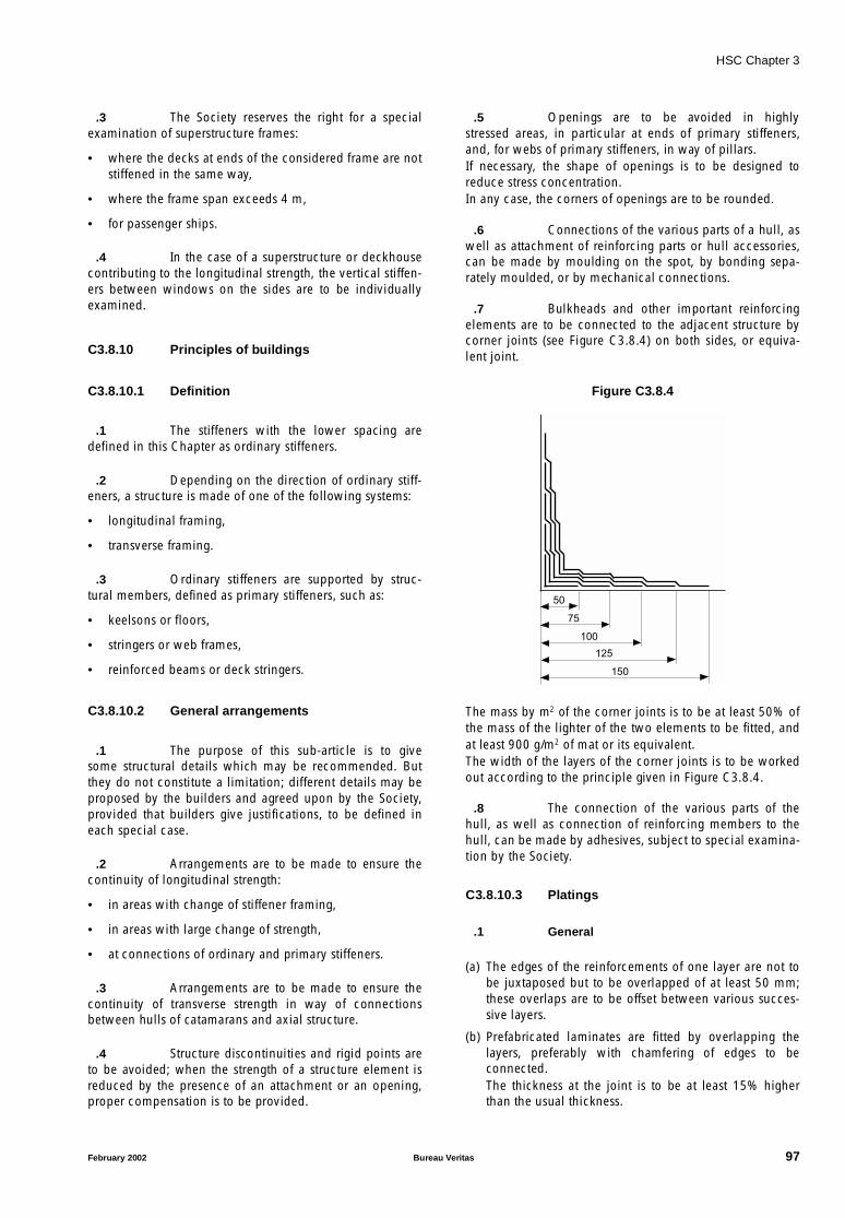
HSC Chapter 3
.3 The Society reserves the right for a specialexamination of superstructure frames:
• where the decks at ends of the considered frame are notstiffened in the same way,
• where the frame span exceeds 4 m,
• for passenger ships.
.4 In the case of a superstructure or deckhousecontributing to the longitudinal strength, the vertical stiffen-ers between windows on the sides are to be individuallyexamined.
C3.8.10 Principles of buildings
C3.8.10.1 Definition
.1 The stiffeners with the lower spacing aredefined in this Chapter as ordinary stiffeners.
.2 Depending on the direction of ordinary stiff-eners, a structure is made of one of the following systems:
• longitudinal framing,
• transverse framing.
.3 Ordinary stiffeners are supported by struc-tural members, defined as primary stiffeners, such as:
• keelsons or floors,
• stringers or web frames,
• reinforced beams or deck stringers.
C3.8.10.2 General arrangements
.1 The purpose of this sub-article is to givesome structural details which may be recommended. Butthey do not constitute a limitation; different details may beproposed by the builders and agreed upon by the Society,provided that builders give justifications, to be defined ineach special case.
.2 Arrangements are to be made to ensure thecontinuity of longitudinal strength:
• in areas with change of stiffener framing,
• in areas with large change of strength,
• at connections of ordinary and primary stiffeners.
.3 Arrangements are to be made to ensure thecontinuity of transverse strength in way of connectionsbetween hulls of catamarans and axial structure.
.4 Structure discontinuities and rigid points areto be avoided; when the strength of a structure element isreduced by the presence of an attachment or an opening,proper compensation is to be provided.
.5 Openings are to be avoided in highlystressed areas, in particular at ends of primary stiffeners,and, for webs of primary stiffeners, in way of pillars.If necessary, the shape of openings is to be designed toreduce stress concentration.In any case, the corners of openings are to be rounded.
.6 Connections of the various parts of a hull, aswell as attachment of reinforcing parts or hull accessories,can be made by moulding on the spot, by bonding sepa-rately moulded, or by mechanical connections.
.7 Bulkheads and other important reinforcingelements are to be connected to the adjacent structure bycorner joints (see Figure C3.8.4) on both sides, or equiva-lent joint.
Figure C3.8.4
The mass by m2 of the corner joints is to be at least 50% ofthe mass of the lighter of the two elements to be fitted, andat least 900 g/m2 of mat or its equivalent.The width of the layers of the corner joints is to be workedout according to the principle given in Figure C3.8.4.
.8 The connection of the various parts of thehull, as well as connection of reinforcing members to thehull, can be made by adhesives, subject to special examina-tion by the Society.
C3.8.10.3 Platings
.1 General
(a) The edges of the reinforcements of one layer are not tobe juxtaposed but to be overlapped of at least 50 mm;these overlaps are to be offset between various succes-sive layers.
(b) Prefabricated laminates are fitted by overlapping thelayers, preferably with chamfering of edges to beconnected.The thickness at the joint is to be at least 15% higherthan the usual thickness.
50
75
100
125
150
February 2002 Bureau Veritas 97
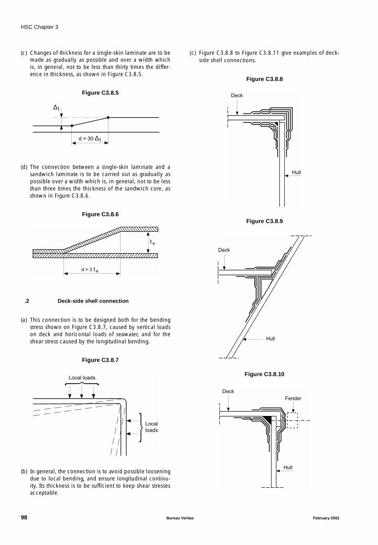
HSC Chapter 3
(c) Changes of thickness for a single-skin laminate are to bemade as gradually as possible and over a width whichis, in general, not to be less than thirty times the differ-ence in thickness, as shown in Figure C3.8.5.
Figure C3.8.5
(d) The connection between a single-skin laminate and asandwich laminate is to be carried out as gradually aspossible over a width which is, in general, not to be lessthan three times the thickness of the sandwich core, asshown in Figure C3.8.6.
Figure C3.8.6
.2 Deck-side shell connection
(a) This connection is to be designed both for the bendingstress shown on Figure C3.8.7, caused by vertical loadson deck and horizontal loads of seawater, and for theshear stress caused by the longitudinal bending.
Figure C3.8.7
(b) In general, the connection is to avoid possible looseningdue to local bending, and ensure longitudinal continu-ity. Its thickness is to be sufficient to keep shear stressesacceptable.
(c) Figure C3.8.8 to Figure C3.8.11 give examples of deck-side shell connections.
Figure C3.8.8
Figure C3.8.9
Figure C3.8.10
d > 30 ∆ t
∆ t
d > 3 ta
t a
Local
loads
Local loads
Hull
Deck
Hull
Deck
Hull
Deck
Fender
98 Bureau Veritas February 2002
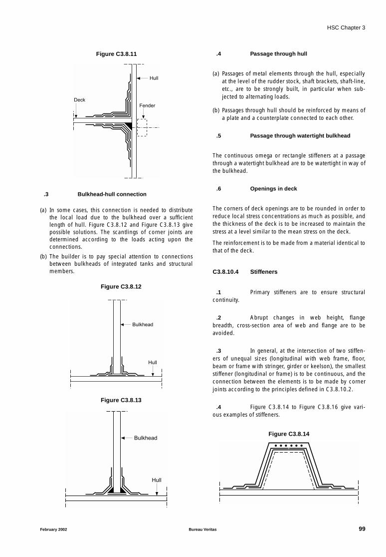
HSC Chapter 3
Figure C3.8.11
.3 Bulkhead-hull connection
(a) In some cases, this connection is needed to distributethe local load due to the bulkhead over a sufficientlength of hull. Figure C3.8.12 and Figure C3.8.13 givepossible solutions. The scantlings of corner joints aredetermined according to the loads acting upon theconnections.
(b) The builder is to pay special attention to connectionsbetween bulkheads of integrated tanks and structuralmembers.
Figure C3.8.12
Figure C3.8.13
.4 Passage through hull
(a) Passages of metal elements through the hull, especiallyat the level of the rudder stock, shaft brackets, shaft-line,etc., are to be strongly built, in particular when sub-jected to alternating loads.
(b) Passages through hull should be reinforced by means ofa plate and a counterplate connected to each other.
.5 Passage through watertight bulkhead
The continuous omega or rectangle stiffeners at a passagethrough a watertight bulkhead are to be watertight in way ofthe bulkhead.
.6 Openings in deck
The corners of deck openings are to be rounded in order toreduce local stress concentrations as much as possible, andthe thickness of the deck is to be increased to maintain thestress at a level similar to the mean stress on the deck.
The reinforcement is to be made from a material identical tothat of the deck.
C3.8.10.4 Stiffeners
.1 Primary stiffeners are to ensure structuralcontinuity.
.2 Abrupt changes in web height, flangebreadth, cross-section area of web and flange are to beavoided.
.3 In general, at the intersection of two stiffen-ers of unequal sizes (longitudinal with web frame, floor,beam or frame with stringer, girder or keelson), the smalleststiffener (longitudinal or frame) is to be continuous, and theconnection between the elements is to be made by cornerjoints according to the principles defined in C3.8.10.2.
.4 Figure C3.8.14 to Figure C3.8.16 give vari-ous examples of stiffeners.
Figure C3.8.14
Hull
Deck
Fender
Hull
Bulkhead
Hull
Bulkhead
February 2002 Bureau Veritas 99

HSC Chapter 3
Figure C3.8.15
Figure C3.8.16
.5 Connections between stiffeners are to ensuregood structural continuity. In particular, the connectionbetween deck beam and frame is to be ensured by means ofa flanged bracket. However, some types of connectionswithout bracket may be accepted, provided that loads arelight enough. In this case, stiffeners are to be considered assupported at their ends.
C3.8.10.5 Pillars
.1 Connections between metal pillars, subjectto tensile loads, and the laminate structure are to bedesigned to avoid tearing between laminate and pillars.
.2 Connections between metal pillars, subjectto compressive loads, and the laminate structure are to becarried out by means of intermediate metal plates. Thewelding of the pillar to the metal plate is to be carried outbefore fitting of the plate on board ship.Figure C3.8.17 gives the principle for connection betweenthe structure and pillars subject to compressive loads.
Figure C3.8.17
C3.8.10.6 Engine seating
.1 The engine seating is to be fitted on specialgirders suitably positioned between floors, which locallyensure sufficient strength with relation to pressure andweight loads.
.2 Figure C3.8.18 gives an example of possibleseating.
Figure C3.8.18
C3.9 Hull appendages
C3.9.1. Propeller shaft brackets
C3.9.1.1 General
.1 For certain ships, the propeller shafting isextended to the propeller bearings clear of the main hull.Propeller shafting is either enclosed in bossing or independ-ent of the main hull and supported by shaft brackets.
C3.9.1.2 Shaft brackets
.1 The scantlings of bracket arms are to be cal-culated as indicated below. For high-powered ships, theSociety may require direct calculations to be carried out.
.2 Bracket arms are to be attached to deepfloors or girders of increased thickness, and the shell platingis to be increased in thickness and suitably stiffened, at thediscretion of the Society. The thickness of the palm connect-ing the arms to the hull, if any, is to be not less than 0,2 dS,where:
dS : Rule diameter, in mm, of the propeller shaft,calculated with the actual mechanicalcharacteristics,
and it is to be connected to the hull by means of throughbolts, fitted with nut and lock nut, in way of the internal hullstructures suitably stiffened.
.3 The arms of V-shaft brackets are to be per-pendicular, as far as practicable.
Deck Deck stiffner
Rigid support
Metallic plateScrewing
Welding
Metallic pillar
Engine mounting
Girder
Web orrigid core
Reinforcement
100 Bureau Veritas February 2002
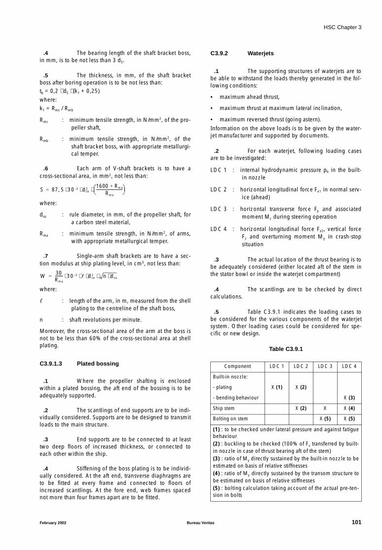
HSC Chapter 3
.4 The bearing length of the shaft bracket boss,in mm, is to be not less than 3 dS.
.5 The thickness, in mm, of the shaft bracketboss after boring operation is to be not less than:tb = 0,2 ⋅ dS ⋅ (k1 + 0,25)
where:k1 = Rms / Rmb
Rms : minimum tensile strength, in N/mm2, of the pro-peller shaft,
Rmb : minimum tensile strength, in N/mm2, of theshaft bracket boss, with appropriate metallurgi-cal temper.
.6 Each arm of V-shaft brackets is to have across-sectional area, in mm2, not less than:
where:
dso : rule diameter, in mm, of the propeller shaft, fora carbon steel material,
Rma : minimum tensile strength, in N/mm2, of arms,with appropriate metallurgical temper.
.7 Single-arm shaft brackets are to have a sec-tion modulus at ship plating level, in cm3, not less than:
where:
: length of the arm, in m, measured from the shellplating to the centreline of the shaft boss,
n : shaft revolutions per minute.
Moreover, the cross-sectional area of the arm at the boss isnot to be less than 60% of the cross-sectional area at shellplating.
C3.9.1.3 Plated bossing
.1 Where the propeller shafting is enclosedwithin a plated bossing, the aft end of the bossing is to beadequately supported.
.2 The scantlings of end supports are to be indi-vidually considered. Supports are to be designed to transmitloads to the main structure.
.3 End supports are to be connected to at leasttwo deep floors of increased thickness, or connected toeach other within the ship.
.4 Stiffening of the boss plating is to be individ-ually considered. At the aft end, transverse diaphragms areto be fitted at every frame and connected to floors ofincreased scantlings. At the fore end, web frames spacednot more than four frames apart are to be fitted.
C3.9.2 Waterjets
.1 The supporting structures of waterjets are tobe able to withstand the loads thereby generated in the fol-lowing conditions:
• maximum ahead thrust,
• maximum thrust at maximum lateral inclination,
• maximum reversed thrust (going astern).
Information on the above loads is to be given by the water-jet manufacturer and supported by documents.
.2 For each waterjet, following loading casesare to be investigated:
LDC 1 : internal hydrodynamic pressure ph in the built-in nozzle
LDC 2 : horizontal longitudinal force Fx1 in normal serv-ice (ahead)
LDC 3 : horizontal transverse force Fy and associatedmoment Mz during steering operation
LDC 4 : horizontal longitudinal force Fx2, vertical forceFz and overturning moment My in crash-stopsituation
.3 The actual location of the thrust bearing is tobe adequately considered (either located aft of the stem inthe stator bowl or inside the waterjet compartment)
.4 The scantlings are to be checked by directcalculations.
.5 Table C3.9.1 indicates the loading cases tobe considered for the various components of the waterjetsystem. Other loading cases could be considered for spe-cific or new design.
Table C3.9.1
S 87 5 10 3– dso2
1600 Rma+Rma
---------------------------- ⋅ ⋅ ⋅,=
W 30Rma
-------- 10 3– dso2 n dso⋅⋅ ⋅ ⋅ ⋅=
Component LDC 1 LDC 2 LDC 3 LDC 4
Built-in nozzle:
- plating X (1) X (2)
- bending behaviour X (3)
Ship stem X (2) X X (4)
Bolting on stem X (5) X (5)
(1) : to be checked under lateral pressure and against fatiguebehaviour(2) : buckling to be checked (100% of Fx transferred by built-in nozzle in case of thrust bearing aft of the stem)(3) : ratio of My directly sustained by the built-in nozzle to beestimated on basis of relative stiffnesses(4) : ratio of My directly sustained by the transom structure tobe estimated on basis of relative stiffnesses(5) : bolting calculation taking account of the actual pre-ten-sion in bolts
February 2002 Bureau Veritas 101
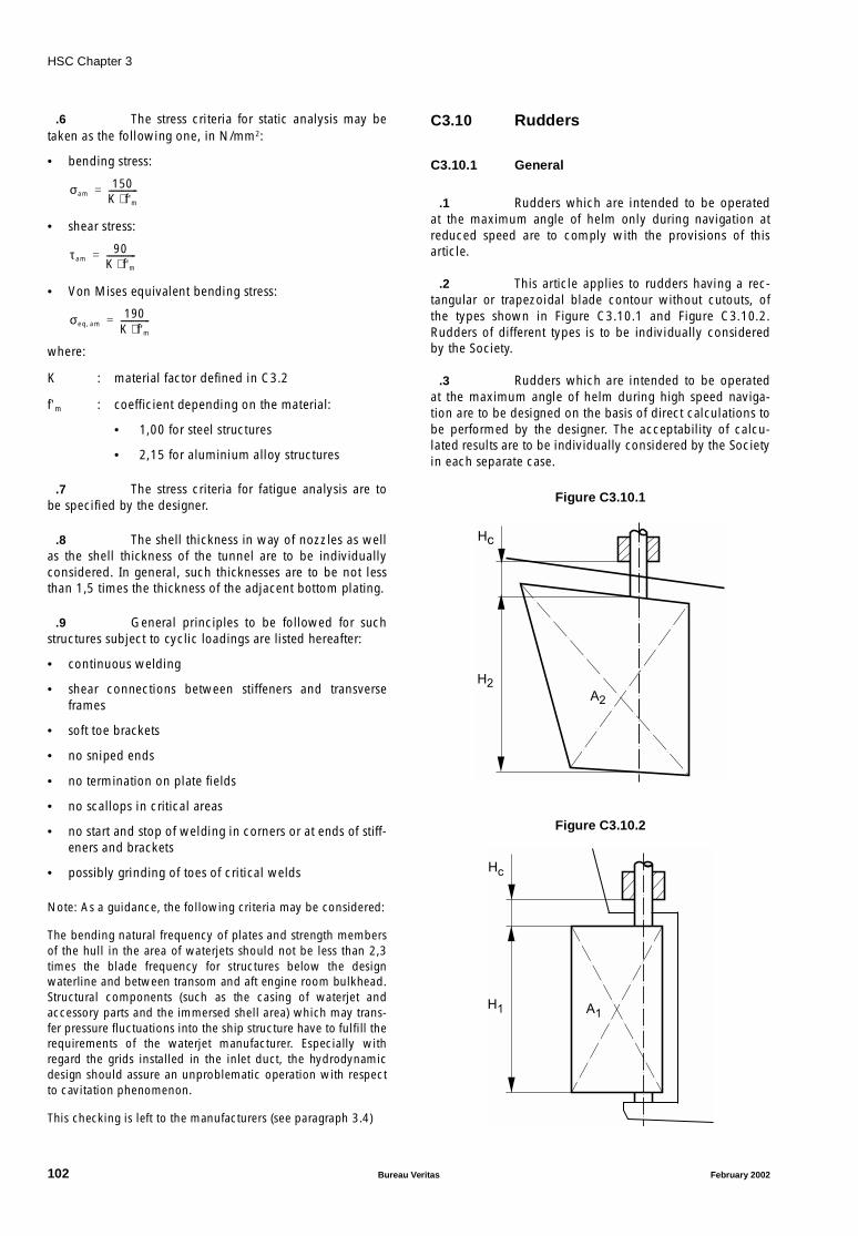
HSC Chapter 3
.6 The stress criteria for static analysis may betaken as the following one, in N/mm2:
• bending stress:
• shear stress:
• Von Mises equivalent bending stress:
where:
K : material factor defined in C3.2
f’m : coefficient depending on the material:
• 1,00 for steel structures
• 2,15 for aluminium alloy structures
.7 The stress criteria for fatigue analysis are tobe specified by the designer.
.8 The shell thickness in way of nozzles as wellas the shell thickness of the tunnel are to be individuallyconsidered. In general, such thicknesses are to be not lessthan 1,5 times the thickness of the adjacent bottom plating.
.9 General principles to be followed for suchstructures subject to cyclic loadings are listed hereafter:
• continuous welding
• shear connections between stiffeners and transverseframes
• soft toe brackets
• no sniped ends
• no termination on plate fields
• no scallops in critical areas
• no start and stop of welding in corners or at ends of stiff-eners and brackets
• possibly grinding of toes of critical welds
Note: As a guidance, the following criteria may be considered:
The bending natural frequency of plates and strength membersof the hull in the area of waterjets should not be less than 2,3times the blade frequency for structures below the designwaterline and between transom and aft engine room bulkhead.Structural components (such as the casing of waterjet andaccessory parts and the immersed shell area) which may trans-fer pressure fluctuations into the ship structure have to fulfill therequirements of the waterjet manufacturer. Especially withregard the grids installed in the inlet duct, the hydrodynamicdesign should assure an unproblematic operation with respectto cavitation phenomenon.
This checking is left to the manufacturers (see paragraph 3.4)
C3.10 Rudders
C3.10.1 General
.1 Rudders which are intended to be operatedat the maximum angle of helm only during navigation atreduced speed are to comply with the provisions of thisarticle.
.2 This article applies to rudders having a rec-tangular or trapezoidal blade contour without cutouts, ofthe types shown in Figure C3.10.1 and Figure C3.10.2.Rudders of different types is to be individually consideredby the Society.
.3 Rudders which are intended to be operatedat the maximum angle of helm during high speed naviga-tion are to be designed on the basis of direct calculations tobe performed by the designer. The acceptability of calcu-lated results are to be individually considered by the Societyin each separate case.
Figure C3.10.1
Figure C3.10.2
σam150
K f'm⋅--------------=
τ am90
K f'm⋅--------------=
σeq am,190
K f'm⋅--------------=
H2
Hc
A2
Hc
H1 A1
102 Bureau Veritas February 2002
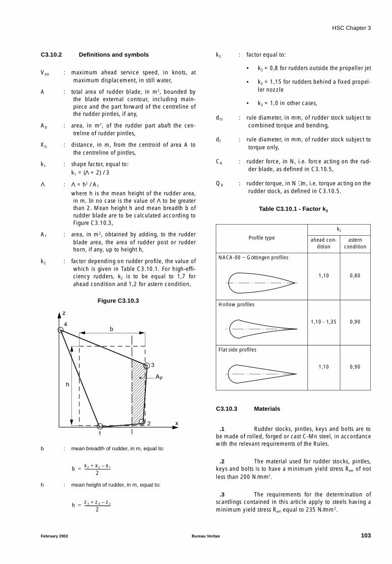
HSC Chapter 3
C3.10.2 Definitions and symbols
VAV : maximum ahead service speed, in knots, atmaximum displacement, in still water,
A : total area of rudder blade, in m2, bounded bythe blade external contour, including main-piece and the part forward of the centreline ofthe rudder pintles, if any,
AD : area, in m2, of the rudder part abaft the cen-treline of rudder pintles,
XG : distance, in m, from the centroid of area A tothe centreline of pintles,
k1 : shape factor, equal to:k1 = (Λ + 2) / 3
Λ : Λ = h2 / AT
where h is the mean height of the rudder area,in m. In no case is the value of Λ to be greaterthan 2. Mean height h and mean breadth b ofrudder blade are to be calculated according toFigure C3.10.3,
AT : area, in m2, obtained by adding, to the rudderblade area, the area of rudder post or rudderhorn, if any, up to height h,
k2 : factor depending on rudder profile, the value ofwhich is given in Table C3.10.1. For high-effi-ciency rudders, k2 is to be equal to 1,7 forahead condition and 1,2 for astern condition,
Figure C3.10.3
b : mean breadth of rudder, in m, equal to:
h : mean height of rudder, in m, equal to:
k3 : factor equal to:
• k3 = 0,8 for rudders outside the propeller jet
• k3 = 1,15 for rudders behind a fixed propel-ler nozzle
• k3 = 1,0 in other cases,
dTF : rule diameter, in mm, of rudder stock subject tocombined torque and bending,
dT : rule diameter, in mm, of rudder stock subject totorque only,
CR : rudder force, in N, i.e. force acting on the rud-der blade, as defined in C3.10.5,
QR : rudder torque, in N ⋅ m, i.e. torque acting on therudder stock, as defined in C3.10.5.
Table C3.10.1 - Factor k2
C3.10.3 Materials
.1 Rudder stocks, pintles, keys and bolts are tobe made of rolled, forged or cast C-Mn steel, in accordancewith the relevant requirements of the Rules.
.2 The material used for rudder stocks, pintles,keys and bolts is to have a minimum yield stress ReH of notless than 200 N/mm2.
.3 The requirements for the determination ofscantlings contained in this article apply to steels having aminimum yield stress ReH equal to 235 N/mm2.
b
z
x
4
h
3
AF
2
1
b x2 x3 x1–+2
---------------------------=
h z3 z4 z2–+2
---------------------------=
Profile type
k2
ahead con-dition
astern condition
NACA-00 − Göttingen profiles
1,10 0,80
Hollow profiles
1,10 - 1,35 0,90
Flat side profiles
1,10 0,90
February 2002 Bureau Veritas 103

HSC Chapter 3
.4 In the case of steels with a yield stress ReH
other than 235 N/mm2, the values of diameters and thick-nesses calculated with the formulae contained in thefollowing sub-articles are to be modified as indicated,depending on the factor K1 obtained from the followingformula:
where:
ReH : minimum yield stress of steel employed, inN/mm2; in no case is ReH to be greater than 450N/mm2 or 0,7 Rm, whichever is less,
Rm : minimum ultimate tensile strength of steelemployed, in N/mm2,
• for ReH > 235 N/mm2: y = 0,75
• for ReH ≤ 235 N/mm2: y = 1,0
.5 In general, significant reductions in rudderstock diameter for the application of steels with ReH > 235N/mm2 may be accepted by the Society, subject to theresults of a calculation to check rudder stock deformation.
.6 Significant rudder stock deformations are tobe avoided so as not to create excessive edge pressures inway of bearings.
.7 Welded parts of rudders are to be made ofrolled hull steels of a type approved by the Society.
C3.10.4 Arrangement
.1 Effective means are to be provided to supportthe weight of the rudder without excessive bearing pressure(e.g. by means of a rudder carrier attached to the upper partof the rudder stock). The hull structure in way of the ruddercarrier is to be suitably strengthened.
.2 Suitable arrangements are to be made to pre-vent the rudder from accidental lifting.
.3 In addition, structural rudder stops of suita-ble strength are to be provided, except where the steeringgear is provided with its own rudder stopping devices.
.4 In rudder trunks which are open to the sea, aseal or stuffing box is to be fitted above the deepest loadwaterline, to prevent water from entering the steering gearcompartment and lubricant being washed away from therudder carrier.
If the top of the rudder trunk is below the deepest waterline,two separate seals or stuffing boxes are to be provided.
C3.10.5 Determination of the force acting on therudder blade and the torque acting onthe rudder stock
.1 The rudder force CR, in N, is to be calculatedby the following formula:CR = 132 ⋅ A ⋅ V2 ⋅ k1 ⋅ k2 ⋅ k3
where:
V : min[VAV, 2/3 ⋅ (VAV + 2 ⋅ L0,5)]
.2 The rudder torque QR, in N ⋅ m, is to be cal-culated for both ahead and astern conditions according tothe formula:QR = CR ⋅ rwhere:
r : distance, in m, equal to:r = b ⋅ (α − kA)for the ahead condition, r is to be taken not lessthan 0,1 ⋅ b,
b : mean breadth of rudder area, in m, measured inaccordance with Figure C3.10.3,
α : • for ahead condition: α = 0,33
• for astern condition: α = 0,66
kA = AF / A
AF being the area, in m2, of the rudder blade portion aforethe centreline of rudder pintles (see Figure C3.10.3).
C3.10.6 Rudder stock
C3.10.6.1 Rudder stock subject to torque
.1 Rudder stocks subject to torque are to havescantlings such that the torsional stress, in N/mm2, does notexceed the following value:τT ALL = 68/K1
.2 The rudder stock diameter is therefore to benot less than dT, in mm, calculated by the followingformula:dT = 4,2 ⋅ (QR ⋅ K1)1/3
C3.10.6.2 Rudder stock subject to combinedtorque and bending
.1 Rudder stocks subject to combined torqueand bending are to have scantlings such that their equiva-lent stress σe, in N/mm2, does not exceed the valuedetermined by the formula:σe ALL = 118 / K1
.2 σe is given by the formula:
where:
K1235ReH
----------
y
=
σe σB2 3 τT
2⋅+=
104 Bureau Veritas February 2002

HSC Chapter 3
σB : bending stress component, in N/mm2, given bythe formula:
τT : torsional stress component, in N/mm2, given bythe following formula:
.3 The rudder stock diameter, in mm, is there-fore to be not less than the value dTF, in mm, calculatedaccording to the formula:
where:
M : bending moment, in N ⋅ m, which may beexpressed as:
M = 0,866 ⋅ (CR / A) ⋅ H
H : • for spade rudders (see Figure C3.10.1):
H = A2 ⋅ (HC + H2 / 2)
• for rudders with 2 bearings (with solepiece)(see Figure C3.10.2):
H = A1 ⋅ a1 ⋅ u ⋅ H1
A1, A2, HC, H1 and H2 are shown in Figure C3.10.1 and Fig-ure C3.10.2.
The values of the coefficients a1 and u are given in TableC3.10.2 as a function of the ratio c, where:
c = H1 / (HC + H1)
Table C3.10.2 - Coefficients a1 and u
.4 The Society may accept bending moments,shear forces and support reaction forces determined by adirect calculation to be performed with reference to thestatic schemes and loading conditions set out in FigureC3.10.4 and Figure C3.10.5.For the rudder in Figure C3.10.4, the load per unit lengthPR, in kN/m, is given by:
For the rudder in Figure C3.10.5, the maximum bendingmoment MB, in N ⋅ m, and support forces B3 and B2, in N,may be determined by the formulae:
B3 = MB / l30
B2 = CR + B3
.5 In general, the diameter of a rudder stocksubject to torque and bending may be gradually taperedabove the upper stock bearing, so as to reach the value of din way of the quadrant or tiller.
Figure C3.10.4
σB10 2 M⋅,
dTF3
---------------------- 103⋅=
τT5 1 QR⋅,
dTF3
--------------------- 103⋅=
dTF dT 1 43--- M
QR
-------
2
⋅+
1 6/
⋅=
c u a1 c u a1
1,000,980,960,940,920,900,880,860,840,820,800,780,76
0,24900,23700,22940,22560,22420,22480,22700,23030,23480,24020,24640,25340,2610
1,0001,0001,0001,0001,0001,0001,0001,0171,0641,1091,1511,1911,229
0,740,720,700,680,660,640,620,600,580,560,540,520,50
0,26940,27840,28810,29840,30940,32120,33360,34680,36080,37570,39150,40840,4264
1,2661,3021,3361,3701,4031,4351,4671,4991,5311,5631,5961,6291,662
PR CR10 3–
10
----------⋅=
MB CR 2010 2C1 C2+( )⋅
3 C1 C2+( )⋅--------------------------------------+
⋅=
40
30
10
20
50
J40
J30
J50
J20
J10 PR
Load
Zc
MB
MR
M Q
FA2
FA1
FA3
February 2002 Bureau Veritas 105
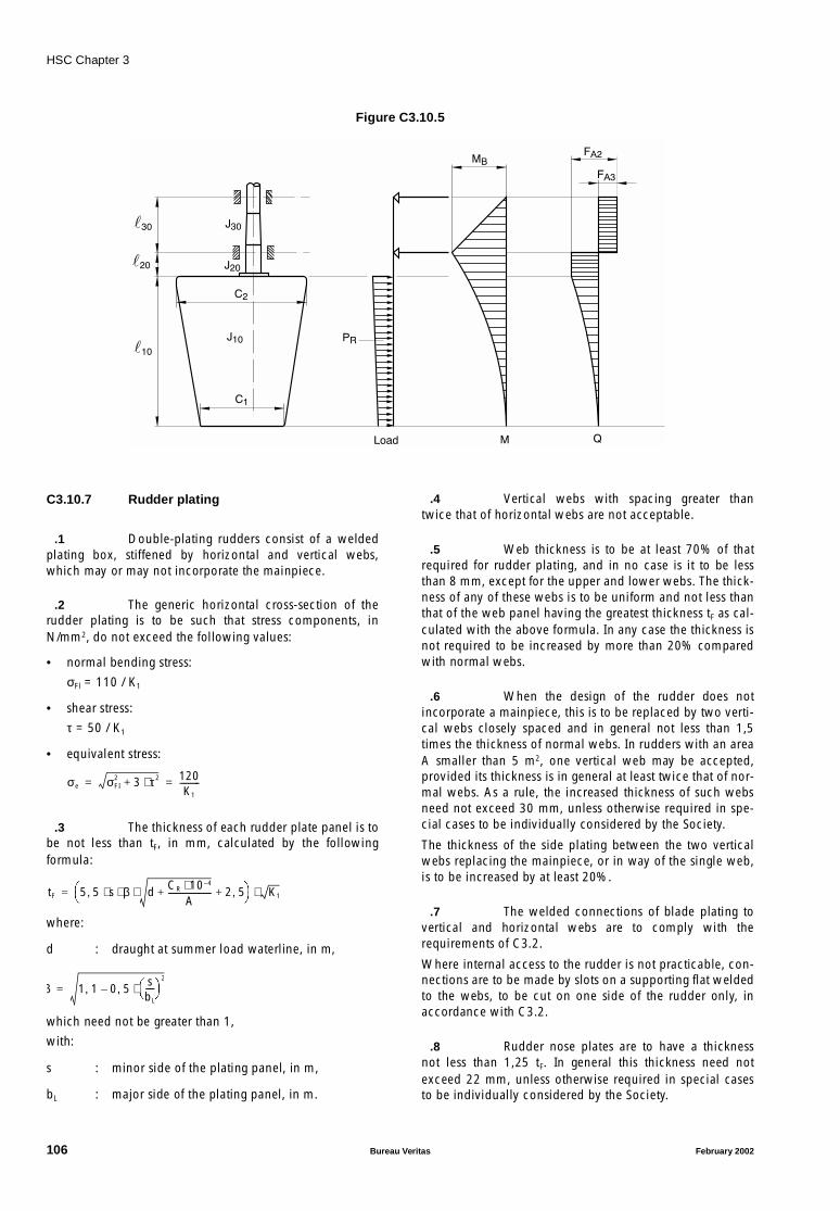
HSC Chapter 3
Figure C3.10.5
C3.10.7 Rudder plating
.1 Double-plating rudders consist of a weldedplating box, stiffened by horizontal and vertical webs,which may or may not incorporate the mainpiece.
.2 The generic horizontal cross-section of therudder plating is to be such that stress components, inN/mm2, do not exceed the following values:
• normal bending stress:
σFl = 110 / K1
• shear stress:
τ = 50 / K1
• equivalent stress:
.3 The thickness of each rudder plate panel is tobe not less than tF, in mm, calculated by the followingformula:
where:
d : draught at summer load waterline, in m,
which need not be greater than 1,
with:
s : minor side of the plating panel, in m,
bL : major side of the plating panel, in m.
.4 Vertical webs with spacing greater thantwice that of horizontal webs are not acceptable.
.5 Web thickness is to be at least 70% of thatrequired for rudder plating, and in no case is it to be lessthan 8 mm, except for the upper and lower webs. The thick-ness of any of these webs is to be uniform and not less thanthat of the web panel having the greatest thickness tF as cal-culated with the above formula. In any case the thickness isnot required to be increased by more than 20% comparedwith normal webs.
.6 When the design of the rudder does notincorporate a mainpiece, this is to be replaced by two verti-cal webs closely spaced and in general not less than 1,5times the thickness of normal webs. In rudders with an areaA smaller than 5 m2, one vertical web may be accepted,provided its thickness is in general at least twice that of nor-mal webs. As a rule, the increased thickness of such websneed not exceed 30 mm, unless otherwise required in spe-cial cases to be individually considered by the Society.
The thickness of the side plating between the two verticalwebs replacing the mainpiece, or in way of the single web,is to be increased by at least 20%.
.7 The welded connections of blade plating tovertical and horizontal webs are to comply with therequirements of C3.2.
Where internal access to the rudder is not practicable, con-nections are to be made by slots on a supporting flat weldedto the webs, to be cut on one side of the rudder only, inaccordance with C3.2.
.8 Rudder nose plates are to have a thicknessnot less than 1,25 tF. In general this thickness need notexceed 22 mm, unless otherwise required in special casesto be individually considered by the Society.
30
20
10
J30
J20
J10
C2
C1
MB
FA2
FA3
PR
Load M Q
σe σFI2 3 τ2⋅+ 120
K1
----------= =
tF 5 5 s β d CR 10 4–⋅A
---------------------+ 2 5,+⋅ ⋅ ⋅, K1⋅=
β 1 1, 0 5sbL
----
2
⋅,–=
106 Bureau Veritas February 2002
HSC Chapter 3
C3.10.8 Rudder pintles
.1 Rudder pintles are to have a diameter notless than the value dA, in mm, calculated by the formula:
dA = 0,35 ⋅ (FA ⋅ K1)1/2
where:
FA : force, in N, acting on the pintle, calculated asspecified in C3.10.8.7.
.2 Provision is to be made for a suitable lockingdevice to prevent the accidental loosening of pintles.
.3 The pintle housings are in general to betapered with the taper ranging:
• from 1:12 to 1:8 for pintles with non-hydraulic assem-bly and disassembly arrangements,
• from 1:20 to 1:12 for pintles with hydraulic assemblyand disassembly arrangements.
The housing height is to be not less than the pintle diameterdA.
.4 The maximum value of the pressure actingon the gudgeons, in N/mm2, calculated by the formula:
is not to exceed the values given in Table C3.10.3, wherehA is the length of contact between pintle and housing,taken to be not greater than 1,2 dA.Values in excess of those given In Table C3.10.3 may beaccepted by the Society on the basis of specific tests.
Table C3.10.3
.5 The thickness of the pintle housing in thegudgeon is to be not less than 0,25 dA.
.6 The manufacturing tolerances, in mm, on thediameter of metal supports are to be less than:dA / 1000 + 1,0In the case of non-metal supports, tolerances are to be eval-uated carefully on the basis of the thermal and distortionproperties of the materials employed; the tolerance on thesupport diameter is in no case to be less than 1,5 mm.
.7 Where direct calculation is used to obtainthe rudder stock stress components, the value FA is also tobe derived from the same calculation.Otherwise, FA is to be calculated from the followingformula:
where:
CR : force, in N, acting on the rudder blade, deter-mined as specified in C3.10.5,
AG : part of the rudder blade area A, in m2, sup-ported by the pintle. AG is to be not lower than:
C3.10.9 Rudder couplings
C3.10.9.1 Horizontal flange couplings
.1 Horizontal flange couplings are to be con-nected by a number nB of fitted bolts not fewer than 6, andthe diameter of which, in mm, is not less than dB given bythe formula:
.2 The thickness of the coupling flange is to benot less than the value tp, in mm, calculated by the follow-ing formula:
In any case tp ≥ 0,9 dB,with dB calculated for a number of bolts not exceeding 8.The symbols used above have the following meaning:
d1 : rule diameter dT or dTF, in mm, of the rudderstock, in compliance with the requirements inC3.10.6,
K1B, K1A, K1P: coefficients depending on the high-strengthsteel used for bolts, rudder stock and couplingflange, respectively, whose values are definedin C3.10.3,
eM : mean distance, in mm, of the bolt axes from thelongitudinal axis through the coupling centre.
.3 The distance from the bolt axes to the exter-nal edge of the coupling flange is generally to be not lessthan 1,2 dB.
.4 A suitable locking device is to be provided toprevent accidental loosening of nuts.
.5 Non-fitted bolts may be used provided that,in way of the mating plane of the coupling flanges, a key isfitted with a section of 0,25 dTx 0,10 dT and keyways inboth the coupling flanges, and provided that at least two ofthe coupling bolts are fitted bolts.
Bearing material qa (N/mm2)
Lignum vitae 2,5
White metal, oil lubricated 4,5
Synthetic material with hardness between 60 and 70 Shore D (1)
5,5
Steel, bronze and hot-pressed bronze-graphite materials (2)
7,0
(1) Indentation hardness test at 23°C and with 50% moistureto be performed according to a recognised standard. Type ofsynthetic bearing materials to be approved by the Society.(2) Stainless and wear-resistant steel in combination withstock liner approved by the Society.
pFFA
dA hA⋅----------------=
FACR
A------ AG⋅=
AG AHC 0 5 H1⋅,+
HC H1+----------------------------------⋅=
dB 0 62, K1B
K1A
-------- d13
nB e⋅ M
----------------⋅ ⋅=
tp dBK1 P
K1B
--------⋅=
February 2002 Bureau Veritas 107

HSC Chapter 3
C3.10.9.2 Vertical flange couplings
.1 Vertical flange couplings are to be connectedby a number nB of fitted bolts not fewer than 8, and thediameter of which, in mm, is not less than dB given by theformula:
d1, K1B and K1A being defined in C3.10.9.1.2 above.
.2 The first moment of area of the sectional areaof bolts about the vertical axis through the centre of thecoupling is to be not less than the value Ms, in cm3,obtained by the formula:
Ms = 0,43 d13 10−6
.3 The thickness of the coupling flange is gener-ally to be not less than dB.
.4 The distance of the bolt axes from the exter-nal edge of the coupling flange is generally to be not lessthan 1,2 dB.
.5 A suitable locking device is to be provided toprevent the accidental loosening of nuts.
C3.10.9.3 Cone couplings
.1 Cone couplings of the shape shown in FigureC3.10.6 (with explanations of symbols in (a) and (b) below)are to be secured by a slugging/hydraulic nut, as the casemay be, provided with an efficient locking device, and withthe following dimensions:
(a) Cone couplings with hydraulic arrangements for assem-bling and disassembling the coupling:
Taper: 1/20 ≤ (δ1 − d0) / tS ≤ 1/12
tS ≥ 1,5 ⋅ d1
dG ≥ 0,65 ⋅ d1
tN ≥ 0,60 ⋅ dG
dN ≥ 1,2 ⋅ d0 and, in any case, dN ≥ 1,2 ⋅ dG
A washer is to be fitted between the nut and the ruddergudgeon not less than 0,13 ⋅ dG in thickness, and withan outer diameter not less than 1,3 ⋅ d0 or 1,6 ⋅ dG,whichever is greater.
(b) Cone couplings without hydraulic arrangements forassembling and disassembling the coupling:
Taper: 1/12 ≤ (δ1 − d0) / tS ≤ 1/8
tS ≥ 1,5 ⋅ d1
dG ≥ 0,65 ⋅ d1
tN ≥ 0,60 ⋅ dG
dN ≥ 1,2 ⋅ d0 and, in any case, dN ≥ 1,2 ⋅ dG.
Figure C3.10.6
.2 The dimensions of the locking nut, in both (a)and (b) above, are given purely for guidance, the determina-tion of adequate scantlings being left to the responsibility ofthe designer.
.3 In cone couplings of type (b) above, a key isto be fitted with a cross-section 0,025 ⋅ dT
2 and keyways inboth the tapered part and the rudder gudgeon.In cone couplings of type (a) above, the key may be omit-ted. In this case, the designer is to provide the Society withshrinkage calculations supplying all data necessary for theappropriate check.
.4 All necessary instructions for hydraulicassembly and disassembly of the nut, including indicationsof the values of all relevant parameters, are to be availableon board.
C3.10.10 Single plate rudders
.1 The mainpiece diameter is to be calculatedaccording to C3.10.4.2.
.2 The mainpiece diameter is to be not less thanthe stock diameter. For spade rudders, the lower third maytaper down to 0,75 times the stock diameter.
.3 The blade thickness tB, in mm, is to be notless than:tB = (1,5 ⋅ s ⋅ VAV + 2,5) ⋅ K1
1/2
where:
s : spacing of stiffening arms, in m, in no case to bemore than 1 m.
.4 The thickness of the arms is to be not lessthan the blade thickness; the section modulus, in cm3, ofthe generic cross-section is to be not less than:ZA = 0,5 ⋅ s ⋅ C1
2 ⋅ VAV2 ⋅ K1
where:
C1 : horizontal distance, in m, from the aft edge ofthe rudder to the cross-section.
dB 0 81 d1⋅, K1B
nB K⋅ 1A
------------------⋅=
d1
d0
tS
tN
dN
dG
108 Bureau Veritas February 2002
HSC Chapter 3
C3.11 Stabilisation means
C3.11.1 General
.1 Two different situations are to be consideredfor the purpose of Chapter 3, depending on the main func-tion of the stabilisation system:
Situation 1: The stabilisation system is associated with thesafe operation of the craft as described in16.1.1. In that case, the system is covered bythe present Rules.
Situation 2: The stabilisation system is only a motion reduc-tion or a ride control system. In such asituation, the system is not covered by thepresent Rules.
C3.11.2 Classification process
.1 For situation 1, the structural design assess-ment process in scope of classification is given hereafter:
• the following structural parts are reviewed, on basis ofdesign loads and safety criteria indicated by thesupplier:
- structure of the stabilisation devices: foils, trim, tabsor interceptors
- ship structure supporting the stabilisation devices
• Only power activated items such as foils, trims, tabs orinterceptors are assessed. The following parts arereviewed:
- hydraulic system used for activation of stabilisationsystem
- associated electrical devices
.2 For situation 2, the structural design assess-ment process in scope of classification is given hereafter:
• only the ship strength in way of stabilisation devices isassessed. Ship structure supporting these devices isreviewed, on basis of design loads and safety criteriaindicated by the supplier:
• Only possible interferences between hydraulic installa-tion and the safety of the craft are of concern. Theapplicable regulations depend on the location of thehydraulic power pack. The working principles are notchecked. However, the hydraulic system documenta-tion is to be submitted.
February 2002 Bureau Veritas 109

HSC Chapter 3
APPENDIX C3A1 SPECIAL REQUIREMENTS FOR SCANTLINGS OF
HYDROFOIL HULL STRUCTURES
C3A1.1 Foreword
.1 The requirements of this Appendix apply tohydrofoils, i.e. craft which can sail both at high speed, withthe hull emerging from the water surface, supported by thehydrodynamic lift of a system of connected underwater foilplanes (foils), and as conventional floating craft duringmanoeuvring operations or in emergency conditions.
.2 Where not expressly specified, the symbolsused here are those already defined in this Chapter.
.3 This Appendix generally covers hydrofoilswith a length L ≤ 35 m and fitted with two foils, a bow andan after foil, and a screw propeller, having a maximum sail-ing speed on foils of 40 knots, and intended for the carriageof passengers and, if applicable, of cargo.
.4 Hydrofoils with characteristics other thanthose above, or which are not designed in accordance withthese Rules, are to be individually considered.
C3A1.2 General
.1 The hull is to be designed with the aim ofachieving safe navigation of the hydrofoil, both whenemerging on foils and when floating under the different dis-placement, trim and stability conditions, in still water andin sea waves, which are expected in service.The designer is to establish, by calculations and, if neces-sary, tank tests on models, hull shapes, weights and theirdistribution, the position, shape and type of foils and thethrust of the propulsion system in order to ensure suitablestructural strength of the hull and safe transverse and longi-tudinal stability of the hydrofoil, with particular reference totransient conditions of lifting from water, alighting on waterand turning.
.2 Hydrofoils covered by this Appendix gener-ally have hard chine hulls as well as bottoms presenting asignificant deadrise, bow foil within 1/3 L of the bow andafter foil within 1/3 L of the stern.Foils may be of the partially submerged Vee (narrow orwide) self-stabilizing type, or of the completely submerged,horizontal non-self-stabilizing type fitted with automaticstabilizing devices; foils may be of the fixed or lifting type.
.3 In the case of hydrofoils with general charac-teristics substantially different from those above or havingspecial arrangements, the Society reserves the right torequire appropriate additional calculations as well as tank
tests on models, followed, if necessary, by exhaustive seatrials before entry into service.
C3A1.3 Definitions and symbols
L : Rule length, in m (see C3.1),
La : longitudinal distance, in m, between mid bowfoil and mid after foil, measured parallel to L,
Lft : overall length, in m,
B : moulded breadth, in m (see C3.1),
Ba : greatest foil breadth, in m,
D : depth, in m (see C3.1),
Da : greatest depth, in m, measured vertically fromthe lower side of the more deeply submergedfoil to the corresponding top of the deck beam,at the side of the main deck,
T : draught, in m (see C3.1),
Ta : greatest draught, in m, of the more deeply sub-merged foil, measured vertically with craft atrest,
T’a : greatest draught, in m, of the more deeply sub-merged foil, measured vertically with full loadcraft on sailing trim on foils,
fm : coefficient depending on the material:
• 1,00 for steel structures
• 1,45 for aluminium alloy structures,
f’m : coefficient depending on the material:
• 1,00 for steel structures
• 2,15 for aluminium alloy structures.
C3A1.4 Documents to be submitted
.1 In addition to the plans and informationlisted in C3.0, the following calculations, specifications andplans (in triplicate) are to be submitted to the Society forapproval, together with the following information:
(a) outer shell expansion, including stiffeners in way offoils, rudder, stern tubes and propeller shaft brackets;
(b) structure of foils and relevant hull connection stiffenersas well as quality of materials employed, with specifica-tion of intended heat treatments and non-destructivetests;
110 Bureau Veritas February 2002
HSC Chapter 3
(c) calculations and diagrams relevant to the longitudinalstrength of the hull;
(d) calculation of foil structure strength, including the spec-ification of the loading conditions considered andrestraints assumed.
.2 Any other documents, calculations and plansdeemed useful by the Society for the purpose of classifica-tion are also to be submitted.
C3A1.5 Longitudinal strength
C3A1.5.1 General
.1 The longitudinal strength of the hull is to becalculated for at least the two conditions specified below,adopting the more severe of the resulting scantlings.
(a) Floating hydrofoilHydrofoil floating in still water,
(b) Emerging hydrofoil on foils
(1) Emerging hydrofoil supported by its foils and con-sidered on its sailing trim in still water without anyadditional motion, taking account, in the actingforces diagram, of the vertical components (lift) ofhydrodynamic forces on the foils,
(2) Hydrofoil in the conditions specified in (1) but in seawaves, taking account of pitching, rolling and heav-ing motions, and of consequent acceleration andforces of inertia.
.2 The calculation of the hull cross-sectionmodulus is to include the shells and associated stiffenerswhich, due to their longitudinal continuity, effectively con-tribute to longitudinal strength.
.3 As regards the acceleration values and wavecharacteristics to be assumed in the calculations, they are toinclude the severest sea conditions expected for the hydro-foil in service, according to the provisions in C3.3.
C3A1.5.2 Allowable stressesRule values of midship section modulusSection modulus calculation
.1 The maximum allowable bending stresses σat deck and bottom and shear stress τ at sides are generallynot to exceed the values given in Table C3A1.1.
Table C3A1.1 - Maximum allowable stresses
In general, maximum σ stresses occur at about 0,5 La, andmaximum τ stresses in way of the bow foil.
.2 Attention is to be paid to scantling distribu-tion for structures contributing to the longitudinal strengthof the different hull zones, so as to avoid structural disconti-nuities, which would give rise to peaks in the diagrams ofmoments of inertia and of section moduli, with consequentabrupt variations in stresses. The structures constituting thehull are also to comply with the requirements for local hullstrength, set out below.
.3 For hydrofoils with length L ≤ 35m, the Rulemidship section moduli at bottom Zb and at deck Zd, in cm3,are given by the formula:Zb = Zd = (6,3 ⋅ La − 60) ⋅ 103
.4 The section modulus is, in any case, to besuch as to comply with the allowable stresses given in TableC3A1.1.
.5 The section moduli of the cross-sections Wb
at bottom and Wd at deck are conventionally obtained bydividing the moment of inertia of the cross-section underconsideration by the vertical distance between the horizon-tal neutral axis and the base line, and by the distancebetween this axis and the top of the deck beam, at the side,of the strength deck, respectively.
.6 To calculate the moment of inertia of theabove cross-sections, the net cross-section of continuouselements contributing to longitudinal strength, and there-fore reduced for openings, manholes and other holes whichare not completely compensated, is to be taken intoaccount; in the case of riveted structures, in contrast, rivetholes in shells and bars are not required to be deductedfrom the strength cross-section.
C3A1.6 Local strength
C3A1.6.1 General
.1 Hull structure dimensions are to comply withthe relevant requirements of this Chapter, considering thecraft as floating, and neglecting dynamic effects due toaccelerations, impact and wave loads.
.2 The structural arrangements to be adopted inthese craft are specified below, together with minimumscantlings to be satisfied in any case.
.3 The scantlings of the outer shell, decks andrelevant stiffeners contributing to local hull strength are tocomply with the requirements of this Appendix. They are tobe increased, if necessary, depending on the longitudinalstrength as required in C3A1.5.
.4 The spacing of secondary stiffeners is, in gen-eral, not to exceed 300 mm, at least in way of foils, themachinery space and forward of the bow foil.
Hydrofoil under conditions
specified in:
σ at bottom (N/mm2)
σ at deck (N/mm2)
τ at sides (N/mm2)
C3A1.5.1.1 (a)C3A1.5.1.1 (b) (1)
45 / (K ⋅ f’m) 45 / (K ⋅ f’m) 40 / (K ⋅ f’m)
C3A1.5.1.1 (b) (2) 85 / (K ⋅ f’m) 85 / (K ⋅ f’m) 70 / (K ⋅ f’m)
February 2002 Bureau Veritas 111

HSC Chapter 3
.5 Primary transverse frames, consisting offloors, side transverses and deck transverses, are to be fittedboth where the structure of ordinary stiffeners is of the trans-verse type and where it is of the longitudinal type.
In the first case, the frames give support to bottom girders,side stringers and deck girders, which in turn, support theordinary shell stiffeners, i.e., floors, webs and beams,respectively; in the second case they support the longitudi-nals directly.
Structures different from the above are to be individuallyconsidered in each case.
C3A1.6.2 Bottom shell plating
.1 The thickness tb, in mm, of the bottom shell,in the area from the bow foil to the stern, is in no case to beless than:
.2 The thickness tk of the keel strake is to be, ingeneral, at least equal to 1,2 times the thickness adopted forthe bottom and in no case less than 4 mm.
.3 The bottom thickness tbf in the area forwardof the bow foil is to be at least 1,2 tb, provided that the take-off speed of the hydrofoil is not greater than approximately20 knots and the maximum sailing speed on foils is notgreater than approximately 40 knots. For greater speeds, thethickness tbf is to be individually considered in each case,depending on the results of calculations and, if necessary,experiments to be performed by the designer, to assess thehydrodynamic force on the shell due to water in the takeoffstage and the wave action on the shell in the sailing condi-tion on foils at maximum service speed.
.4 Takeoff speed is intended as the minimumspeed necessary to lift the hull on foils in still water.
.5 In way of foils, the bottom thickness is to beincreased appropriately and in no case is it to be less than,in mm:
C3A1.6.3 Side shell plating
.1 The thickness ts, in mm, of the side shell is tobe not less than:
.2 The thickness ts, in mm, from 0,1 L aft thebow foil to 0,1 L forward of such foil is to be not less than:
.3 The thickness tsh of the sheerstrake, for thewhole hull length, is to be at least equal to that of the corre-sponding side.
.4 Where, on the sheerstrake, side ports or sidescuttles or other large openings are fitted, the thickness is tobe increased such as to compensate these openings.
.5 The thickness tsh is also to be increased inway of end bulkheads of any castles, or, in any case, in wayof steps in the strength deck.
.6 In way of foils, the side thickness is to besuitably increased and is, in no case, to be less than, in mm:
C3A1.6.4 Deck and flat plating
.1 The thickness td, in mm, of the deck plating isto be not less than:
.2 The thickness tst of the stringer plate of thestrength deck is to be at least equal to that adopted for thesheerstrake or for the remaining deck plating, whichever isgreater.
.3 The thickness, in mm, of decks below thestrength deck, generally consisting of flats, is to be not lessthan:
• if the ’tween deck is intended for accommodation orsimilar:
• if the deck forms a tank bottom or tank top:
C3A1.6.5 Bottom structure
.1 For the bottom, longitudinal framing extend-ing through the whole length is generally required, exceptfor extreme stern and extreme bow areas, where the framingis generally transverse.
.2 In way of the bow foil and after foil, ordinaryfloors of suitable scantlings, to be individually considered ineach case, are to be fitted. In way of the fore foil, the floorspacing is generally to be one half the frame spacing.
.3 In the machinery space, at least two girderson each side are to be fitted, at least one of which is to befitted in way of one of the engine seating girders.
.4 In the area forward of the bow foil, at leastone girder on each side is to be fitted. The height, in gen-eral, is to be at least equal to that of the bottom transverses,and preferably located in the same plane as a deck girder, iffitted. The girder thickness is to be not less than, in mm:
3 fm K⋅ ⋅
5 fm K⋅ ⋅
3 fm K⋅ ⋅
5 fm K⋅ ⋅
5 fm K⋅ ⋅
3 fm K⋅ ⋅
2 fm K⋅ ⋅
2 5 fm K⋅ ⋅,
3 fm K⋅ ⋅
112 Bureau Veritas February 2002
HSC Chapter 3
.5 At the bow foil and after foil, the number andscantlings of the floors are to be individually considered ineach case, depending on the type of structure proposed. Inany case, two floors belonging to complete transverse rings(side and deck transverses) are to be fitted, and located oneforward and the other aft of the hull penetrations of the bowfoil bearing arm.
Intermediate floors in this area are to be positioned,between those usually fitted at each frame spacing, and allsuch bottom transverses are to have a section modulus of atleast 1,25 times that required for the area aft of the engineroom.
.6 In the area forward of the bow foil, the floorsare generally to have a section modulus of at least 1,8 timesthat required for the area aft of the engine room and a spac-ing not greater than four web spacings. In the usual case ofbottoms presenting forward a deadrise angle greater thanapproximately 25°, the floors are to have a horizontal upperedge and a height of at least 0,2 ⋅ D in the centreline.
.7 In the case the takeoff and sailing speed ofthe hydrofoil are greater than those specified in C3A1.6.2.3,the scantlings of the forward floors are to be individuallyconsidered in each case.
C3A1.6.6 Side structure
.1 This structure may be of the transverse type,i.e. consisting of ordinary webs, supported by stringers (orflats) and side transverses belonging to the primary trans-verse rings, or, for hydrofoils with length L greater thanapproximately 20 m, of the longitudinal type, i.e. consistingof longitudinals supported by side transverses belonging tothese rings.
.2 Continuity of the longitudinals is to beensured, considering their contribution to the longitudinalstrength of the hull.
.3 Side transverses are to be fitted for the pur-pose of supporting the longitudinals, and side stringers (orflats), to be individually considered in each case, are to befitted in way of and forward of the machinery space.
.4 In way of foils, scantlings are to be individu-ally considered in each case.
.5 The section modulus of the side transversesforward of the bow foil is to be individually considered ineach case: in any event, two side transverses are to be fittedin way of the floors located forward and aft of the hull pen-etrations of the bow foil bearing arm, for which in general:
h / S ≥ 0,25
where h is the web height and S is the conventional span ofthe side transverse.
.6 In way of the bow and after foils and in thecase of side transverses supporting deck bracket-transverses,the provisions of C3A1.6.5.5 to C3A1.6.5.7 apply.
.7 In the area forward of the bow foil, the sidetransverses are preferably to have an h/S ratio of at least 0,2.As regards the case of high hydrofoil speeds, the provisionsof C3A1.6.5.5 to C3A1.6.5.7 are to be complied with.
C3A1.6.7 Deck structure
.1 Strength deck stiffeners may be of the trans-verse type where constituted by beams supported by girderswhich are in turn supported by deck transverses belongingto the primary transverse rings, which may or may not beassociated with pillars; such stiffeners are of the longitudi-nal type where they consist of longitudinals supported bythe deck transverses.
The latter structure is recommended where L > 20 m.
.2 Stiffeners of decks below the strength deckand stiffeners of flats intended for passenger accommoda-tion or forming the top of the machinery space are to have asection modulus not less than, in cm3:
4 ⋅ fm ⋅ K
.3 Where the deck or flat forms the top of a tankfor liquids, the provisions of C3.7 or C3.8 are to be com-plied with.
.4 The scantlings of stiffeners fitted on accountof special structural requirements, for example in way offoils, are to be individually considered in each case.
.5 Deck transverses are to be fitted in way ofside transverses, so as to constitute members of completetransverse rings.
.6 They may instead be of the bracket type inthe general case of hydrofoils for which L is less thanapproximately 15 m, and fitted with long deck openings; insuch case, deck transverses, continuous from side to side,are to be fitted at least immediately aft and forward of themachinery space and forward of the bow foil. An intermedi-ate flat, between bottom and deck, is to be fitted at least inthe area aft of the machinery space.
.7 The scantlings of deck transverses in way offoils and the scantlings of panting deck transverses fitted inthe fore peak, at approximately mid-depth between bottomand deck, are to be individually considered in each case.
.8 Owing to their span (roughly 0,3 to 0,5 m),deck transverses of the bracket type are generally composedof wide brackets connected to the web frame and the sidestringer of the deck opening. The scantlings of such decktransverses are to be individually considered in each case.
February 2002 Bureau Veritas 113

HSC Chapter 3
C3A1.6.8 Watertight bulkheads
.1 For the hydrofoils considered in this Appen-dix, four watertight subdivision bulkheads are generallyrequired to be fitted as follows:
• watertight collision bulkhead, located not less than0,05 ⋅ L from the forward perpendicular and, in general,not more than 0,08 ⋅ L from the same perpendicular,
• fore and after watertight bulkhead of the machineryspace,
• after watertight bulkhead, located, in general, about0,05 ⋅ L from the aft perpendicular, but in no case morethan 0,08 ⋅ L from the same perpendicular.
.2 In the case of hydrofoils intended for the car-riage of passengers, the watertight subdivision bulkheadsare also to satisfy the relevant requirements of Chapter 2.
C3A1.7 Foils
C3A1.7.1 General
.1 The type, shape and location of foils is to bedetermined by the designer based upon the general designprovisions specified in C3A1.2, taking account of the factthat the essential function of foils is to support the hull,emerging at a sufficient height above the water surface so asto allow sailing even in waves, while ensuring the stabilityof the hydrofoil at the same time.
After determining these characteristics, the strength calcula-tions for foils and relevant hull supporting connections areto be performed.
.2 In the case of hydrofoils with foil types otherthan those considered below, the Society reserves the right,after examining the calculations, to require special checksand tests, as specified in C3A1.2.
.3 The foil profile and shape are to comply withthe provisions of the present article and, even when sailingin waves, to avoid cavitation phenomena dangerous for thestability of the hydrofoil.
.4 Calculation of the forces acting on the hydro-foil may be performed by considering the craft in sailingcondition on foils in still water.
.5 The following acting forces are assumed:
• hydrofoil weight, at least in the two conditions of fullload and without passengers,
• hydrodynamic resistance of the bow foil and after foiland associated lift,
• thrust of propellers.
.6 For the equilibrium, the algebraic sum of theacting forces and relevant moments with respect to thehydrofoil’s centre of gravity is obviously to be equal to zero.
.7 In addition, the hydrofoil is to be consideredduring its turning manoeuvres. This means that water thruston the rudder, whose action gives rise to variations in thehydrodynamic resistance and in the lift distribution on foils,as well as the forces generated by balancing flaps, are to beadded to the forces above.
.8 Moreover, taking into account the mostsevere dynamic conditions expected for the hydrofoil inservice, the above forces and, in addition, forces of inertiagenerated by rolling, pitching and heaving, including thoseduring takeoff from the water and alighting on the water, areto be considered in the designer’s calculations.
The characteristics of such motions, i.e. oscillation ampli-tude and period, and the consequent acceleration fromwhich the forces of inertia originate, are to be consideredindividually by the Society in each case, based upon theexperience already gained, if the hydrofoil under considera-tion is similar to previous ones which have given goodresults in service, or, otherwise, upon the results of exhaus-tive tank tests on models, as well as sea trials on thehydrofoil itself, before entry into service.
C3A1.7.2 Foil strength calculations
.1 In the case of V-type or W-type foils, each isusually connected, by quasi-vertical or vertical arms, to ahorizontal member, fitted transversely with respect to thehull, and supported by special hull structures.
The foils and arms may therefore in such cases be consid-ered, overall, as a system consisting of beams and jointssupported by the hull structures.
.2 The forces acting on the foils consist ofhydrodynamic resistance and lift, as well as the reactions ofthe structures mentioned above which balance such forces.
.3 Strength calculations are therefore to takeaccount of the nature of the restraints from the hull on thereticular system and acting forces, in the loading conditionsspecified above, as well as of the mechanical properties ofthe materials employed, which are generally high-strengthwelding steels.
.4 In particular, diagrams of bending momentsand axial and shear forces acting on the foils are to be plot-ted and the stresses deriving from them are to be calculated.
114 Bureau Veritas February 2002

HSC Chapter 3
C3A1.7.3 Foil construction
.1 The foil joints are generally constituted offorged or cast steel, or are obtained from plate, while thebeams are to be made of fabricated plating, and connec-tions are to be welded.
.2 Since, due to the shape and dimensions ofthe foil profile, the foils themselves are not internally acces-sible, and therefore back-welding of all welded joints is notpossible, the constructional plan is to specify special typesof edge preparation, welding sequence and performance, toensure the absence of defects and minimise internal stressesdue to shrinkage at welds.
In particular, the number of slot-welded joints on plating isto be minimised.
.3 Materials are to be tested by the Society, andelectrodes and welding processes are to be recognised assuitable in accordance with the Rules.
.4 Butt-joints are to be subjected to radio-graphic examination and, if inaccessible from one side, tomagnetic particle or dye-penetrant examination.
.5 Depending on the quality of the materialadopted and on welding processes, the Society reserves theright to require thermal stress-relieving in the furnace afterwelding.
February 2002 Bureau Veritas 115
HSC Chapter 3
APPENDIX C3A2 SPECIAL REQUIREMENTS FOR SCANTLINGS OF
AIR-CUSHION VEHICLE HULL STRUCTURES
C3A2.1 Foreword
.1 The requirements of this Appendix apply to“flexible skirt hovercraft”, i.e. air-cushion vehicles with adownwardly-extending flexible structure used to contain ordivide the air cushion.This type of air-cushion vehicle is amphibious.
.2 Unless otherwise specified, the symbols usedhere are those already defined in C3.1.
C3A2.2 General
C3A2.2.1 Definitions and symbols
.1 Weight and masses
Light weight: the weight of the craft without cargo, fuel,lubricating oil and water in tanks, without con-sumable stores, passengers, crews or personaleffects.
Light mass: the mass of the craft under the sameconditions.
Maximum operational weight: the overall weight at whichthe craft is permitted to operate under normalconditions.
Maximum operational mass: the mass of the craft under thesame conditions.
.2 Dimensions
The main dimensions of an hovercraft are determined forthe following situations:
• stationary,
• under maximum load,
• afloat.
L : length, in m, equal to the length of the rigid hullmeasured on the waterline at draught T, andnot to be less than 95% of the air cushion lon-gitudinal connection,
B : breadth, in m, equal to the broadest part of therigid hull measured on the waterline at draughtT. B is not to be less than 95% of the air cush-ion transverse connection,
T : draught, in m, (see C3.1),
D : depth, in m, (see C3.1).
The structure is divided into several substructures depend-ing on the type of supported loads (overall forces, localforces, concentrated loads, etc.) and design methods.
C3A2.2.2 Main structure
.1 The main structure comprises all structuralmembers which contribute to overall strength, i.e. memberswhich support the overall longitudinal and transverse bend-ing forces as well as overall torsional forces resulting fromasymmetrical loads (e.g. craft in flying or floating situationon diagonal wave).
.2 Besides its resistance to overall forces, thisstructure is to be capable of supporting certain local forcesexerted by local loads, or loads distributed in areas of lim-ited dimensions.
.3 It generally includes:
• platform above the air-cushion with its primary and sec-ondary, transverse, longitudinal and diagonal stiffeners,
• watertight compartments giving buoyancy,
• decks, floors, bulkheads as well as side walls, super-structure and deckhouse shell plating rigidly connectedto the platform and for buoyancy compartments.
C3A2.2.3 Secondary structures
.1 The secondary structure completes the mainstructure by contributing to the safety and the protection ofthe craft against bad weather and wave impacts.They are designed to support only local stresses.
.2 These secondary structures comprise allmembers not rigidly connected to the main structure suchas certain platforms, internal or external bulkheads andwalls or access doors.
C3A2.2.4 Additional structures
.1 Additional structures cover all arrangementsattached to the main structure and taking a prominent partin the craft’s operation and safety.They generally create concentrated stresses in the mainstructure, and possibly, secondary structures.
116 Bureau Veritas February 2002
HSC Chapter 3
.2 These structures mainly comprise:
• skirt connections to the structure,
• seatings and foundations for propelling unit, ventilatingplants and associated auxiliaries,
• supporting brackets for steering and trim control appara-tus, which can be aerial or submerged,
• onshore or offshore anchoring and mooring as well astowing arrangements,
• landing and ground support arrangements for amphibi-ous air-cushion vehicles,
• wheelhouse, if not integrated in the structure.
C3A2.3 Documents to be submitted
C3A2.3.1 Documents submitted for information
.1 The designer is to provide a general arrange-ment drawing showing the general structural layout,intended use of different spaces and tanks, and location ofpropelling, lifting and operating installations.
.2 In addition to the information stipulated inC3.0, weight balances are to be provided for the followingcases:
• light weight air-cushion vehicle,
• air-cushion vehicle at operating full load.
.3 In addition, for air-cushion vehicles carryingcargo, weight balances are to be submitted for all interme-diate loading cases considered by the designer andindicated in the operating manual.
.4 Each loading case is to be indicated with therelevant position of the main masses.
C3A2.3.2 Justification of scantlings
.1 Scantlings are to be justified by calculationnotes indicating relevant loads, calculation methods andcomputation results.
.2 When computer calculations are carried out,the software is to be indicated, and indications are to becommunicated with regard to structure description, bound-ary conditions and the way loads are introduced.The results of these calculations are to be submitted to theSociety.
.3 Justification can be based on recognisedexperimental results: recorded for similar structures andcorrected, if required, to allow for minor variations of cer-tain parameters, the effects of which have been suitablyevaluated.In that case, tested structures, test conditions, methods andresults, as well as variations in the parameters and theireffects on the structure in question, are to be clearlydefined.
C3A2.3.3 Drawings for approval
.1 In addition to the plans listed in TableC3.0.1, the following drawings are to be submitted to theSociety for approval:
• bottoms and walls limiting air cushion,
• side shell and side walls,
• air-cushion lining and subdivision arrangements,
• seatings, foundations, supporting brackets and air pipesof lifting plant,
• skegs, rudders and control systems,
• landing, ground supporting and mooring arrangements,if any, including handling equipment,
• details of all types of assembling arrangements andscantlings of connections,
• hoisting and handling equipment, if any, used on board.
.2 This is not an exhaustive list; other drawingsmay be required.
C3A2.4 Scantlings criteria
C3A2.4.1 General
.1 Each constituent part of the structure is to bedesigned to withstand a combination of loads which consti-tute the scantling criteria, without sustaining damage ordistortions likely to affect the good working order of the air-cushion vehicle.
.2 These criteria are determined on the basis ofthe craft’s characteristics, its performances, and operationalrestrictions dictated by the intended type of service.
C3A2.4.2 Types of stresses
.1 General stresses
General stresses result from the overall forces applied to thestructure in order to maintain the air-cushion vehicle in bal-ance in a given situation.These loads are, on the one hand, loads due to masses(forces of inertia) and, on the other hand, external loads cre-ated by environmental conditions, as defined in C3A2.4.3.General stresses induce distortions and overall stresses inthe main structure.
.2 Local stresses
Local stresses are created by masses which are directly sup-ported by internal forces and external loads applied locally.They modify the stress values resulting from general stressesfor a specific component of the main structure.They are used as a basis for the scantlings of the compo-nents of secondary and additional structures.
February 2002 Bureau Veritas 117
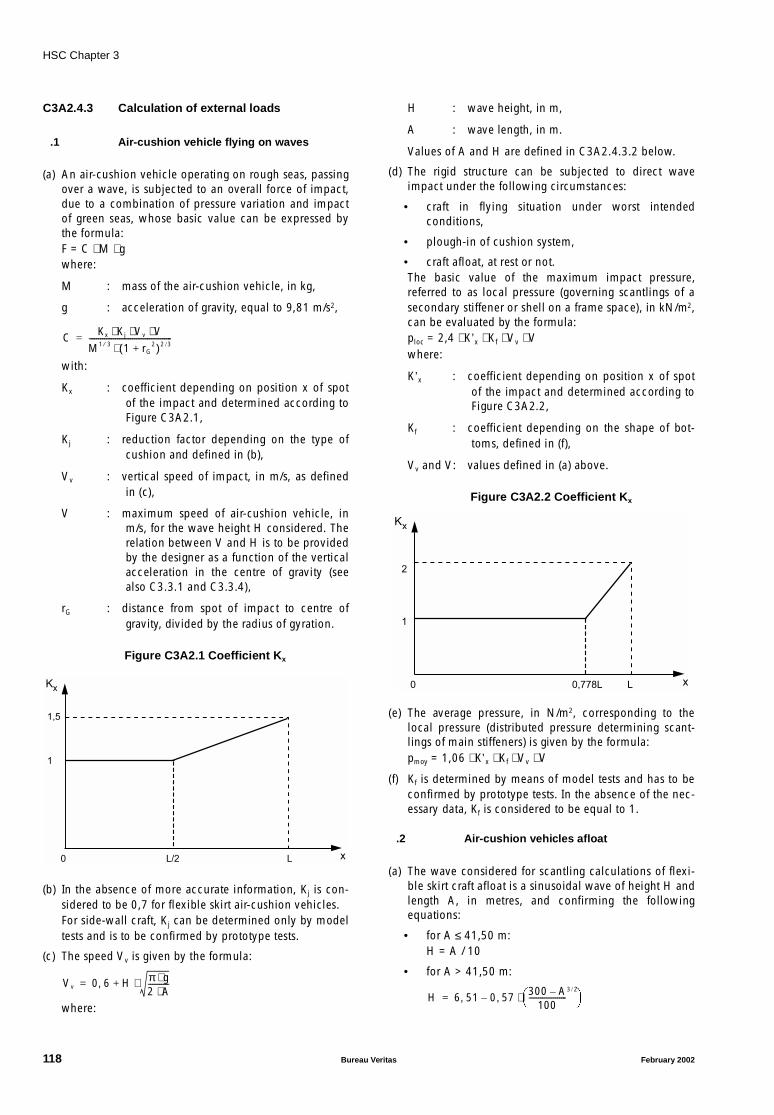
HSC Chapter 3
C3A2.4.3 Calculation of external loads
.1 Air-cushion vehicle flying on waves
(a) An air-cushion vehicle operating on rough seas, passingover a wave, is subjected to an overall force of impact,due to a combination of pressure variation and impactof green seas, whose basic value can be expressed bythe formula:F = C ⋅ M ⋅ gwhere:
M : mass of the air-cushion vehicle, in kg,
g : acceleration of gravity, equal to 9,81 m/s2,
with:
Kx : coefficient depending on position x of spotof the impact and determined according toFigure C3A2.1,
Kj : reduction factor depending on the type ofcushion and defined in (b),
Vv : vertical speed of impact, in m/s, as definedin (c),
V : maximum speed of air-cushion vehicle, inm/s, for the wave height H considered. Therelation between V and H is to be providedby the designer as a function of the verticalacceleration in the centre of gravity (seealso C3.3.1 and C3.3.4),
rG : distance from spot of impact to centre ofgravity, divided by the radius of gyration.
Figure C3A2.1 Coefficient Kx
(b) In the absence of more accurate information, Kj is con-sidered to be 0,7 for flexible skirt air-cushion vehicles.For side-wall craft, Kj can be determined only by modeltests and is to be confirmed by prototype tests.
(c) The speed Vv is given by the formula:
where:
H : wave height, in m,
A : wave length, in m.
Values of A and H are defined in C3A2.4.3.2 below.
(d) The rigid structure can be subjected to direct waveimpact under the following circumstances:
• craft in flying situation under worst intendedconditions,
• plough-in of cushion system,
• craft afloat, at rest or not.The basic value of the maximum impact pressure,referred to as local pressure (governing scantlings of asecondary stiffener or shell on a frame space), in kN/m2,can be evaluated by the formula:ploc = 2,4 ⋅ K’x ⋅ Kf ⋅ Vv ⋅ Vwhere:
K’x : coefficient depending on position x of spotof the impact and determined according toFigure C3A2.2,
Kf : coefficient depending on the shape of bot-toms, defined in (f),
Vv and V: values defined in (a) above.
Figure C3A2.2 Coefficient Kx
(e) The average pressure, in N/m2, corresponding to thelocal pressure (distributed pressure determining scant-lings of main stiffeners) is given by the formula:pmoy = 1,06 ⋅ K’x ⋅ Kf ⋅ Vv ⋅ V
(f) Kf is determined by means of model tests and has to beconfirmed by prototype tests. In the absence of the nec-essary data, Kf is considered to be equal to 1.
.2 Air-cushion vehicles afloat
(a) The wave considered for scantling calculations of flexi-ble skirt craft afloat is a sinusoidal wave of height H andlength A, in metres, and confirming the followingequations:
• for A ≤ 41,50 m:H = A / 10
• for A > 41,50 m:
C Kx Kj Vv V⋅ ⋅ ⋅M1 3⁄ 1 rG
2+( )2 3/⋅--------------------------------------------=
1,5
0
1
Kx
xL/2 L
Vv 0 6 H π g⋅2 A⋅-----------⋅+,=
2
0
1
Kx
xL0,778L
H 6 51 0 57 300 A–100
--------------------3 2/
⋅,–,=
118 Bureau Veritas February 2002
HSC Chapter 3
(b) The value H is defined by the designer on the basis ofthe limit operating conditions indicated in the Enclosureof the Class Certificate and on the midship sectiondrawing (see C3.3.1 and C3.3.4).
The worst conditions are generally encountered when Ais approximately equal to:
• L for head wave,
• B for beam wave.
.3 Wind effects
(a) Two cases are to be considered, depending on whetherthe craft is at rest or in operation.
(b) When the craft is moored to the ground or afloat, eachcomponent of the entire structure has to be able to with-stand the pressure and/or vacuum forces produced by asteady wind, blowing horizontally, depending on theworst direction for each component considered, at aspeed of 70 knots.
More severe conditions may be required for air-cushioncraft intended to operate in particularly exposed areas.
Less severe conditions can be accepted for small ormedium-size craft which can easily be wind-screened.
(c) During navigation under the worst intended conditions,it is to be checked that each constituent part of the air-cushion vehicle is capable of withstanding the pressureand vacuum forces produced by gusts increasing thetrue wind speed by at least 30% of its nominal value(mean value observed during 10 minutes).
This horizontal component is to obtain the most unfa-vourable direction for the particular constituent part.
These forces are, if applicable, to be consideredtogether with the forces in C3A2.4.3.1 and C3A2.4.3.2above.
(d) If no other indications are available, the dynamic pres-sures, exerted by the wind on a vertical element, can beestimated by means of the following formulae, inkN/m2, depending on the altitude above sea level of theelement and wind speed vw, in knots:
• between 0 and 5 m above the sea level:
q1 = 1,50 ⋅ 10 − 3 ⋅ vw2
• at 10 m or more:
q2 = 0,16 ⋅ 10 − 3 ⋅ vw2
Between 5 m and 10 m, there is a linear variation of qbetween the two preceding values.
Note: These pressure variations depending on altitude takeaccount of the degree of seawater saturation of the sea-air.Other corrections are to be made to these values to accountfor the type of forces (pressure or vacuum), the lines of theair-cushion vehicle, etc. These corrections are to be justi-fied by the designer.
.4 Other meteorological conditions
(a) Besides the loads mentioned in C3A2.4.3.1 toC3A2.4.3.3, and according to the navigation area, loadsresulting from the accumulation of snow and ice on cer-tain parts such as roofs, side walls, steering andpropelling installations, are to be accounted for, ifapplicable.
(b) Generally, for air-cushion vehicles built in series, themost severe conditions are to be considered dependingon various intended navigation areas.
C3A2.4.4 Calculation of internal loads
.1 Loads on flooring (decks)
(a) Normal static loads on various floorings are to be indi-cated in the builder’s technical specifications.
(b) Scantlings of floorings in compartments intended forcarriage of passengers are calculated on the basis of0,75 kN per passenger.
However, this value may be reduced to 0,60 kN if it canbe justified.
(c) For guidance, the following values can be adopted forflooring scantlings, depending on use:
• flooring of passenger compartment: even load of2,50 kN/m2 (or loads indicated in (b) with no morethan 4 passengers per square metre),
• flooring of luggage compartments: density 150kg/m3 (load evenly distributed),
• flooring supporting miscellaneous cargoes: density700 kg/m3 (load evenly distributed),
• flooring supporting cars: 3,0 kN per wheel (loadlocally distributed on the surface on tyre tracks),
• flooring supporting commercial vehicles: 65,0 kNper wheel.
These preceding loads are nominal static loads.
(d) When the air-cushion vehicle is afloat on waves, and aflooring is exposed to green seas, its strength is also tobe checked with regard to hydrostatic pressure, accord-ing to the parameters defined in C3A2.4.3.2.
.2 Loads due to propelling and steeringinstallations
(a) These loads are applied to the structure through the con-nections of foundations, seatings, gantries, etc.supporting the propelling engine, the lifting installation,their auxiliaries as well as steering gear such as ruddersand skegs.
February 2002 Bureau Veritas 119
HSC Chapter 3
(b) For propelling and lifting plants, loads are calculated onthe basis of the most critical situations to be expected(e.g. breakdowns, sudden changes in engine speed,reverse propeller pitch).
(c) For steering arrangements, loads are either contractualloads (power rudders) or loads actually encountered.The latter can be deduced from calculations or tests.The basic contractual loads applied by the pilot on thecontrols are as follows:
• 0,46 kN on a control stick or control wheel ahead orreverse gear,
• 0,28 kN on a control stick - laterally,
• 0,185 kN on a control wheel - tangential action,
• 0,60 kN on pedals or levers.
(d) See also C3A2.7.8.
.3 Loads due to tests
(a) Tests are to be carried out to check the tightness of inte-grated buoyancy compartments, fuel tanks and variousliquid tanks.
Scantlings are to be such that no permanent distortionwill remain after tests at the pressures indicated in (b)and (c) below (verification at yield stress).
(b) Buoyancy compartments are generally tested with com-pressed air at a pressure of not more than 0,2 bar(pressure is controlled by means of a U-shape stand-pipe), after application of sealing material, if required.
(c) Fuel tanks and liquid tanks are tested with water at apressure equal to a stand-pipe of 2,40 m above theuppermost point of the compartment.
Fuel and liquid tanks are also to be able, without break-ing, to withstand the forces produced by the movementof liquids in case of collision as mentioned in C3A2.7.8.
C3A2.5 Load factors
C3A2.5.1 General
.1 Load factors are increasing coefficients usedto determine, on the basis of nominal static loads, thedynamic forces supported by the structure, referred to asbasic loads.
.2 These coefficients depend on actual move-ments of air-cushion vehicle, speed, acceleration, turning,etc. and on movements imposed on the craft due to externalfactors such as wave, wave impact or gusts of wind.
.3 Load factors are estimated on the basis ofvarious accelerations for which reference values are speci-fied in C3A2.5.2 and C3A2.5.3 below.
C3A2.5.2 Accelerations under normal serviceconditions
.1 For the calculation of local forces, includingthose resulting from liquid loads, acceleration can be atleast any of the values between the following limits:
• from 0,7 g upwards to 0,8 g downwards in addition withgravity,
• from 0,5 g afterwards to 1,0 g forwards,
• from 0,5 g on one side to 0,5 g on the other side.
.2 The preceding values apply to air-cushionvehicles for “open sea” or “restricted open sea” service.
.3 Reductions may be allowed for craft for“moderate environment” or “smooth sea” service (seeC3.3.1).
C3A2.5.3 Accelerations in the event of collision
.1 The relevant authorities require certaininstallations and connections to be capable of withstandingthe forces resulting from such more severe accelerationsthan the preceding in C3A2.5.2.
.2 The values to be taken into account are:
• from 3 g upwards to 4 g downwards,
• from 0 g to 6 g forwards,
• from 0 g to 3 g afterwards,
• from 0 g to 3 g sideways.
C3A2.5.4 Application procedure
.1 For certain calculations, a combination ofaccelerations in several directions needs to be considered,but the final acceleration value is not to exceed:
• 1 g for horizontal accelerations in normal service,
• 6 g for accelerations in the event of collision.
.2 The directions mentioned in C3A2.5.2,C3A2.5.3 and C3A2.5.4 refer to inertia forces which tend todisplace each mass in relation to the entire air-cushionvehicle.
.3 The vertical and transverse accelerationsindicated in C3A2.5.2 can, if necessary, be modified inagreement with the Society, at the designer’s request, pro-vided that a complete file is submitted with sufficientexperimental justifications.These values can also vary depending for which part thescantlings are to be calculated and its location in relation tothe craft’s centre of gravity.
.4 In certain specific cases, the load factor canbe considered as equal to 1, for example when the forcesapplied are constant or vary slowly (jacking operations, tra-versing operations at low speed, etc.).
120 Bureau Veritas February 2002
HSC Chapter 3
.5 The basic loads due to dynamic forces areloads which easily occur in service under the worstintended conditions.
They are deducted from nominal static loads by means ofthe appropriate load factors.
C3A2.6 Strength limits and safetycoefficients
C3A2.6.1 General
.1 Strength limits
(a) Strength limits are increasing factors applied to basicloads, to account for exceptional overloads incurred bythe structure under critical foreseen conditions.
(b) Strength limits also help to provide for part of the doubtinherent in calculation theories or methods.
(c) Basic loads multiplied by strength limits give the maxi-mum loads that the structure has to withstand withoutincurring permanent distortions.
.2 Safety coefficients
(a) Safety coefficients take into account:
• uncertainties inherent in certain assumptions,
• more or less accurate calculation methods,
• flaws and allowances accepted for materials andassembling procedures,
• residual manufacturing stresses,
• variations, in time, in the characteristics of certainmaterials,
• strength reductions due to corrosion or scoringcaused by the surrounding environment.
(b) Maximum loads multiplied by relevant safety coeffi-cients define the most extreme loads that the structure isto be capable of withstanding without breaking or col-lapsing, while incurring possible permanent distortions.
C3A2.6.2 Summary table
.1 Table C3A2.1 summarises the methods forload calculations.
Table C3A2.1 - Load calculation methods
.2 The basic load corresponds to the worstintended conditions. The maximum load corresponds to thecritical design conditions.
C3A2.6.3 Numerical values
.1 Values of strength limits and safety coeffi-cients are determined by the designer in agreement with theSociety.
.2 Strength limits may vary depending on theimportance of the part for which scantlings are to be calcu-lated, and the type of loads applied.
In general, strength limits may not exceed 1,5.
.3 In general, the safety coefficients are consid-ered as equal to 1,5.
However, the accelerations indicated in C3A2.5.3, in theevent of collisions, are the most extreme values, so that theresulting loads are also extreme loads (safety coefficientequal to 1).
Higher values may, nevertheless, be required (recom-mended value: 2) for parts subject to extremelyconcentrated forces such as hoisting, trucking, towing andanchoring points.
C3A2.7 Cases of scantlings
C3A2.7.1 General
.1 Loads to be applied to the structure aredetermined by considering the air-cushion vehicle in the sit-uations outlined in C3A2.7.1.2 and C3A2.7.1.3.
.2 Situations corresponding to normal serviceunder specific limit conditions determine general structurescantlings.
.3 Exceptional situations are taken into accountonly to determine scantlings of parts which are directlyinvolved, and their connections to the structures.
.4 Depending on the scantling case, the result-ing loads are either basic loads or maximum loads (extremeloads in collision situations).
C3A2.7.2 Flying situation
.1 The different flying situations are:
• on still water,
• on head waves,
• on abeam waves,
• on diagonal waves.
1 - Nominal static load x Load factor = basic load
2 - Basic load x Strength limit = maximum load
3 - Maximum load x Safety coefficient = extreme load
February 2002 Bureau Veritas 121

HSC Chapter 3
.2 The transient stages, involving a changeoverfrom one of the preceding elementary situations to another,are also to be considered.The flying situation on still water is, in particular, to make itpossible to determine the forces generated by operationsunder the most severe conditions, as a result of:
• speed,
• accelerations or decelerations,
• lifting height,
• turning and yawing characteristics,
• trim and heeling variations.
.3 The envelope of maximum forces is obtainedby considering all loading cases defined on the operatingmanual, as well as maximum speeds authorised, dependingon various wave heights up to the maximum design height.
.4 The different cases above determine:
• general forces of overall longitudinal and transversebending, as well as overall tension and correspondingshear forces,
• local forces produced by wave impacts, gusts of wind,propelling machinery, skirt connections, etc.
C3A2.7.3 Floating situation
.1 The different floating situations to be consid-ered are:
• on still water,
• on head waves,
• on abeam waves,
• on diagonal waves (line of wave crests almost parallel toone of the craft’s diagonals).
.2 All loading cases defined in the operatingmanual are to be considered, as for flying situations.
.3 The speed to be considered is either the max-imum self-propelling speed, if this possibility exists, or elsethe maximum towing speed.
.4 The above cases determine both general andcorresponding local forces.
C3A2.7.4 Landing
.1 This refers to amphibious air-cushion vehi-cles normally parking on land.
.2 The worst landing case is defined by the fol-lowing parameters:
• maximum lifting height,
• highest possible descending speed,
• worst mass, trim, heeling and horizontal speed condi-tions (e.g. asymmetrical landing supports, gusts ofwind).
.3 This case determines local forces applied tolanding-gear connecting points.It can also determine certain general forces, in particular fortorsion resulting from asymmetrical landing supports.
C3A2.7.5 Hoisting
.1 This case affects the scantlings of hoistingpoints and their connections to the structure (distribution ofconcentrated forces).
.2 It also to be checked that this case does notgenerate general bending or torsional forces (asymmetricalhoisting) leading to stresses that exceed allowable values.
.3 The maximum authorized mass for hoistingis to be determined by the designer and indicated in themaintenance manual.
C3A2.7.6 Trucking
.1 This case determines the scantlings of thetrucking contact pieces and their attachments to the struc-ture (local forces).
.2 The verification required in C3A2.7.5 is alsoto be carried out.
.3 The maximum authorized mass for truckingis to be determined by the designer and indicated in themaintenance manual.
C3A2.7.7 Anchoring - Mooring - Towage
.1 These situations determine the concentratedforces applied to points of ground or quay anchoring andmooring, together with towage.
.2 They can also affect the scantlings of someparts of the structure subjected to aerodynamic forces, andloads, if any, due to accumulated snow and/or ice (seeC3A2.4.3.3 and C3A2.4.3.4).
.3 The maximum authorized forces to beapplied at the preceding points are equal to the respectivebreaking loads of anchor, mooring and towing cable lines.
C3A2.7.8 Collisions
.1 It is to be checked that certain parts of thestructure, equipment and components are capable of with-standing the exceptional dynamic forces resulting from acollision.
.2 These verifications comprise, without beingconfined, to:
• scantlings of engine foundations, seatings and gantriesof propelling installation,
• structure at connecting points of these parts,
122 Bureau Veritas February 2002

HSC Chapter 3
• cargo and luggage lashing points,
• vehicle wedging and securing points,
• securing arrangements of passenger seats,
• fuel and lube oil tanks, integrated or not (motions ofliquids).
.3 The forces are deduced from the accelera-tions mentioned in C3A2.5.3. They correspond to extremeloads.
C3A2.8 Allowable stresses
C3A2.8.1 General
.1 The maximum allowable stresses for a spe-cific material or construction are deduced from theminimum corresponding mechanical properties, deter-mined through tests.
.2 The strength of the various parts of the struc-ture and associated connections is checked by means ofstatic strength calculations, according to yield stress, tensilestrength or buckling, whichever is the most severe.
.3 Computer calculations are to satisfy the indi-cations in C3A2.3.2.
.4 The various stresses in a structural part arecalculated on the basis of the different cases of scantlingsdefined in C3A2.7.
Suitable combinations are to be operated at each point. Inparticular, stresses due to both general and local forces areto be considered.
.5 Resulting stress values are to be corrected toaccount for:
• stress concentration around cutouts and discontinuitiesin plates and stiffeners,
• local deterioration of mechanical properties aroundconnections (e.g. welded or glued joints).
C3A2.8.2 Verifications based on extreme loads
.1 Breaking
(a) Application of extreme loads to the structure allowsmaximum elementary stresses at each point of a struc-tural part or a construction to be calculated.
(b) If the total stress resulting from the appropriate combi-nation of elementary stresses at any point is a pullingforce, it may not, under any circumstances, exceed theminimum breaking load at this point.
.2 Bucking
(a) If the total stress resulting from the appropriate combi-nation of elementary stresses at any point is acompressive force, it may not, under any circumstances,exceed the collapse limit (general buckling) at thispoint.
(b) The collapse limit is to be determined, if required, onthe basis of reduced elasticity modulus values of materi-als (corrected accordingly to the correspondingPoisson’s ratio).The moments of inertia are, themselves, to be reduced,to take into account only the “equivalent width” ofplates (width capable of bearing the general bucklingrate without local buckling).
C3A2.8.3 Verification based on maximum loads
.1 Application of maximum loads to the struc-ture allows corresponding elementary stresses at each pointof a structural part or a construction to be calculated.
.2 The total stress resulting from the appropriatecombination of elementary stresses at any point may not bemore that the least of the following values:
• minimum conventional yield stress of the material orconstruction,
• minimum breaking load of the material or constructiondivided by 1,5.
C3A2.8.4 Verification based on basic loads
.1 No systematic verification is made for basicloads.
.2 However, since these loads are supported bythe structure in normal service, they can be used to checkthe fatigue strength of certain components or constructions.
C3A2.9 Distortions
C3A2.9.1 Distortions under maximum loads
.1 No permanent distortions are to remain afterapplication of maximum loads.
.2 Each structural component is to be sodesigned that the distortions sustained can in no way affectthe good working order of the other components of the air-cushion vehicle.
C3A2.9.2 Distortions under extreme loads
.1 Permanent distortions under extreme loadsmay be accepted, provided that neither the craft’s safety norproper operation of its main components is affected.
February 2002 Bureau Veritas 123
HSC Chapter 4
CHAPTER 4 ACCOMMODATION AND ESCAPE MEASURES
C4.0 Documents to be submitted
The following plans and documents are to be submitted atleast in triplicate, for approval. The Society reserves its rightto ask for supplementary copies, if deemed necessary inparticular cases.
.1 Windows, arrangements and details.
.2 Plan showing the arrangement of means ofcommunication.
.3 Calculation of the collision load and relevantarrangement of the accommodation spaces (containing theindication of seat characteristics, arrangement and installa-tion, the characteristics of the safety belts).
.4 Plans showing the means of escape and themeans of access to the various craft spaces.
.5 Evacuation procedure and evacuation timecalculation.
Further documentation may be required if deemed neces-sary by the Society.
4.1 General
4.1.1 Public spaces and crew accommodationshall be designed and arranged so as to protect the occu-pants from unfavourable environmental conditions and tominimize the risk of injury to occupants during normal andemergency conditions.
4.1.2 Spaces accessible to passengers shall notcontain controls, electrical equipment, high-temperatureparts and pipelines, rotating assemblies or other items, fromwhich injury to passengers could result, unless such itemsare adequately shielded, isolated, or otherwise protected.
4.1.3 Public spaces shall not contain operatingcontrols unless the operating controls are so protected andlocated that their operation by a crew member shall not beimpeded by passengers during normal and emergencyconditions.
4.1.4 Windows in passenger and crew accommo-dation shall be of adequate strength and suitable for theworst intended conditions specified in the Permit to Oper-ate and be made of material which will not break intodangerous fragments if fractured.
4.1.5 The public spaces, crew accommodationand the equipment therein shall be designed so that eachperson making proper use of these facilities will not sufferinjury during craft's normal and emergency start, stop andmanoeuvring in normal cruise and in failure or maloperationconditions.
4.2 Public address and informationsystem
4.2.1 A general emergency alarm system shall beprovided. The alarm shall be audible throughout all thepublic spaces, corridors and stairways, crew accommoda-tion and normal crew working spaces and open decks, andthe sound pressure level shall be at least 10 dB(A) aboveambient noise levels under way in normal cruise operation.The alarm shall continue to function after it has been trig-gered until it is normally turned off or is temporarilyinterrupted by a message on the public address-system.
4.2.2 There shall be a public address system cover-ing all areas where passengers and crew have access,escape routes, and places of embarkation into survival craft.The system shall be such that flooding or fire in any com-partment does not render other parts of the systeminoperable. The public address system and its performancestandards shall be approved by the Administration havingregard to the recommendations developed by theOrganization.
Note: Refer to the Recommendations on performance standards forpublic address systems on passenger ships, including cabling(MSC/Circ. 808) and the Code on Alarms and Indicators, 1995(resolution A.830(19)).
4.2.3 All passenger craft shall be equipped withilluminated or luminous notices or video information sys-tem(s) visible to all sitting passengers, in order to notifythem of safety measures.
4.2.4 The master shall, by means of the publicaddress system and the visual information system, be ableto request passengers “please be seated” when found to beappropriate to safeguard passengers and always when thesafety level 1 according to table 1 of annex 3 is exceeded.
124 Bureau Veritas February 2002
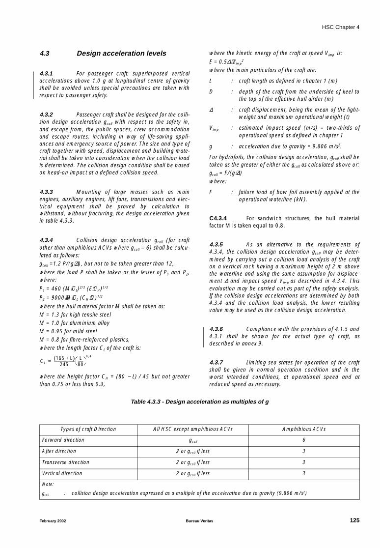
HSC Chapter 4
4.3 Design acceleration levels
4.3.1 For passenger craft, superimposed verticalaccelerations above 1.0 g at longitudinal centre of gravityshall be avoided unless special precautions are taken withrespect to passenger safety.
4.3.2 Passenger craft shall be designed for the colli-sion design acceleration gcoll with respect to the safety in,and escape from, the public spaces, crew accommodationand escape routes, including in way of life-saving appli-ances and emergency source of power. The size and type ofcraft together with speed, displacement and building mate-rial shall be taken into consideration when the collision loadis determined. The collision design condition shall be basedon head-on impact at a defined collision speed.
4.3.3 Mounting of large masses such as mainengines, auxiliary engines, lift fans, transmissions and elec-trical equipment shall be proved by calculation towithstand, without fracturing, the design acceleration givenin table 4.3.3.
4.3.4 Collision design acceleration gcoll (for craftother than amphibious ACVs where gcoll = 6) shall be calcu-lated as follows:gcoll =1.2 P/(g⋅∆), but not to be taken greater than 12,
where the load P shall be taken as the lesser of P1 and P2,where:
P1 = 460 (M⋅CL)2/3 (E⋅CH)1/3
P2 = 9000⋅M⋅CL (CH⋅D)1/2
where the hull material factor M shall be taken as:M = 1.3 for high tensile steelM = 1.0 for aluminium alloyM = 0.95 for mild steelM = 0.8 for fibre-reinforced plastics,where the length factor CL of the craft is:
where the height factor CH = (80 − L) / 45 but not greaterthan 0.75 or less than 0.3,
where the kinetic energy of the craft at speed Vimp is:
E = 0.5∆⋅Vimp2
where the main particulars of the craft are:
L : craft length as defined in chapter 1 (m)
D : depth of the craft from the underside of keel tothe top of the effective hull girder (m)
∆ : craft displacement, being the mean of the light-weight and maximum operational weight (t)
Vimp : estimated impact speed (m/s) = two-thirds ofoperational speed as defined in chapter 1
g : acceleration due to gravity = 9.806 m/s2.
For hydrofoils, the collision design acceleration, gcoll shall betaken as the greater of either the gcoll as calculated above or:gcoll = F/(g⋅∆)where:
F : failure load of bow foil assembly applied at theoperational waterline (kN).
C4.3.4 For sandwich structures, the hull materialfactor M is taken equal to 0,8.
4.3.5 As an alternative to the requirements of4.3.4, the collision design acceleration gcoll may be deter-mined by carrying out a collision load analysis of the crafton a vertical rock having a maximum height of 2 m abovethe waterline and using the same assumption for displace-ment ∆ and impact speed Vimp as described in 4.3.4. Thisevaluation may be carried out as part of the safety analysis.If the collision design accelerations are determined by both4.3.4 and the collision load analysis, the lower resultingvalue may be used as the collision design acceleration.
4.3.6 Compliance with the provisions of 4.1.5 and4.3.1 shall be shown for the actual type of craft, asdescribed in annex 9.
4.3.7 Limiting sea states for operation of the craftshall be given in normal operation condition and in theworst intended conditions, at operational speed and atreduced speed as necessary.
Table 4.3.3 - Design acceleration as multiples of g
CL165 L+( )
245------------------------ L
80------
0 4,
=
Types of craft Direction All HSC except amphibious ACVs Amphibious ACVs
Forward direction gcoll 6
After direction 2 or gcoll if less 3
Transverse direction 2 or gcoll if less 3
Vertical direction 2 or gcoll if less 3
Note:
gcoll : collision design acceleration expressed as a multiple of the acceleration due to gravity (9.806 m/s2)
February 2002 Bureau Veritas 125
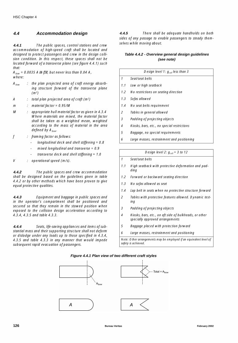
HSC Chapter 4
4.4 Accommodation design
4.4.1 The public spaces, control stations and crewaccommodation of high-speed craft shall be located anddesigned to protect passengers and crew in the design colli-sion condition. In this respect, these spaces shall not belocated forward of a transverse plane (see figure 4.4.1) suchthat:Abow = 0.0035 A⋅m⋅f⋅V, but never less than 0.04 A,where:
Abow : the plan projected area of craft energy absorb-ing structure forward of the transverse plane(m2)
A : total plan projected area of craft (m2)
m : material factor = 0.95/M
M : appropriate hull material factor as given in 4.3.4 Where materials are mixed, the material factorshall be taken as a weighted mean, weightedaccording to the mass of material in the areadefined by Abow.
f : framing factor as follows:
- longitudinal deck and shell stiffening = 0.8
- mixed longitudinal and transverse = 0.9
- transverse deck and shell stiffening = 1.0
V : operational speed (m/s).
4.4.2 The public spaces and crew accommodationshall be designed based on the guidelines given in table4.4.2 or by other methods which have been proven to giveequal protective qualities.
4.4.3 Equipment and baggage in public spaces andin the operator's compartment shall be positioned andsecured so that they remain in the stowed position whenexposed to the collision design acceleration according to4.3.4, 4.3.5 and table 4.3.3.
4.4.4 Seats, life-saving appliances and items of sub-stantial mass and their supporting structure shall not deformor dislodge under any loads up to those specified in 4.3.4,4.3.5 and table 4.3.3 in any manner that would impedesubsequent rapid evacuation of passengers.
4.4.5 There shall be adequate handholds on bothsides of any passage to enable passengers to steady them-selves while moving about.
Table 4.4.2 - Overview general design guidelines(see note)
Figure 4.4.1 Plan view of two different craft styles
Design level 1: gcoll less than 3
1 Seat/seat belts
1.1 Low or high seatback
1.2 No restrictions on seating direction
1.3 Sofas allowed
1.4 No seat belts requirement
2 Tables in general allowed
3 Padding of projecting objects
4 Kiosks, bars, etc., no special restrictions
5 Baggage, no special requirements
6 Large masses, restrainment and positioning
Design level 2: gcoll = 3 to 12
1 Seat/seat belts
1.1 High seatback with protective deformation and pad-ding
1.2 Forward or backward seating direction
1.3 No sofas allowed as seat
1.4 Lap belt in seats when no protective structure forward
2 Tables with protective features allowed. Dynamic test-ing
3 Padding of projecting objects
4 Kiosks, bars, etc., on aft side of bulkheads, or other specially approved arrangements
5 Baggage placed with protection forward
6 Large masses, restrainment and positioning
Note: Other arrangements may be employed if an equivalent level of safety is achieved.
Abow
Total = Abow
A A
126 Bureau Veritas February 2002
HSC Chapter 4
4.5 Seating construction
4.5.1 A seat shall be provided for each passengerand crew member for which the craft is certified to carry.Such seats shall be arranged in enclosed spaces.
4.5.2 Seats fitted in addition to those requiredunder 4.5.1 and which are not permitted to be used in haz-ardous navigational situations or potentially dangerousweather or sea conditions need not comply with 4.5 or 4.6.Such seats shall be secured according to 4.4.4 and clearlyidentified as not being able to be used in hazardoussituations.
4.5.3 The installation of seats be shall be such as toallow adequate access to any part of the accommodationspace. In particular, they shall not obstruct access to, or useof, any essential emergency equipment or means of escape.
4.5.4 Seats and their attachments, and the struc-ture in the proximity of the seats, shall be of a form anddesign, and so arranged, such as to minimize the possibilityof injury and to avoid trapping of the passengers after theassumed damage in the collision design condition accord-ing to 4.4.1. Dangerous projections and hard edges shall beeliminated or padded.
4.5.5 Seats, seat belts, seat arrangements and adja-cent parts such as tables shall be designed for the actualcollision design acceleration as specified in 4.3.4.
4.5.6 All seats, their supports and their deckattachments shall have good energy-absorbing characteris-tics and shall meet the requirements of annex 10.
4.6 Safety belts
4.6.1 One-hand-release safety belts of three-pointtype or with shoulder harness shall be provided for all seatsfrom which the craft may be operated for all craft with thegcoll acceleration from the collision design accelerationexceeding 3g, as prescribed in 4.3.4.
4.6.2 Safety belts shall be provided on passengerseats and crew seats, if necessary, to obtain the protectiveperformance measures described in annex 10.
4.7 Exits and means of escape
4.7.1 In order to ensure immediate assistance fromthe crew in an emergency situation, the crew accommoda-tion, including any cabins, shall be located with due regardto easy, safe and quick access to the public spaces from
inside the craft. For the same reason, easy, safe and quickaccess from the operating compartment to the publicspaces shall be provided.
4.7.2 The design of the craft shall be such that alloccupants may safely evacuate the craft into survival craftunder all emergency conditions, by day or by night. Thepositions of all exits which may be used in an emergency,and of all life-saving appliances, the practicability of theevacuation procedure, and the evacuation time to evacuateall passengers and crew shall be demonstrated.
4.7.3 Public spaces, evacuation routes, exits, life-jacket stowage, survival craft stowage, and the embarkationstations shall be clearly and permanently marked and illumi-nated as required in chapter 12.
4.7.4 Each enclosed public space and similar per-manently enclosed space allocated to passengers or crewshall be provided with at least two exits as widely separatedas practical. All exits shall clearly indicate the directions tothe evacuation station and safe areas. On category A craftand cargo craft, at least one exit shall give access to theevacuation station serving the persons in the enclosedspace considered, and all other exits shall give access to aposition on the open deck from which access to an evacua-tion station is provided. On category B craft, exits shallprovide access to the alternative safe area required by7.11.1; external routes may be accepted providing that therequirements of 4.7.3 and 4.7.11 are complied with.
4.7.5 Subdivision of public spaces to provide ref-uge in case of fire may be required in compliance with7.4.4.1 and 7.11.1.
4.7.6 Exit doors shall be capable of being readilyoperated from inside and outside the craft in daylight and indarkness. The means of operation shall be obvious, rapidand of adequate strength. Doors along escape routesshould, wherever appropriate, open in the direction ofescape flow from the space served.
4.7.7 The closing, latching and locking arrange-ments for exits shall be such that it is readily apparent to theappropriate crew member when the doors are closed and ina safe operational condition, either in direct view or by anindicator. The design of external doors shall be such as tominimize the possibility of jamming by ice or debris.
4.7.8 The craft shall have a sufficient number ofexits which are suitable to facilitate the quick and unim-peded escape of persons wearing approved lifejackets inemergency conditions, such as collision damage or fire.
4.7.9 Sufficient space for a crew member shall beprovided adjacent to exits for ensuring the rapid evacuationof passengers.
February 2002 Bureau Veritas 127

HSC Chapter 4
4.7.10 All exits, together with their means of open-ing, shall be adequately marked for the guidance ofpassengers. Adequate marking shall also be provided for theguidance of rescue personnel outside the craft.
4.7.11 Footholds, ladders, etc., provided to giveaccess from the inside to exits shall be of rigid constructionand permanently fixed in position. Permanent handholdsshall be provided whenever necessary to assist personsusing exits, and shall be suitable for conditions when thecraft has developed any possible angles of list or trim.
4.7.12 At least two unobstructed evacuation pathsshall be available for the use of each person. Evacuationpaths shall be disposed such that adequate evacuation facil-ities will be available in the event of any likely damage oremergency conditions, and evacuation paths shall haveadequate lighting supplied from the main and emergencysources of power.
4.7.13 The width of corridors, doorways and stair-ways which form part of the evacuation paths shall be notless than 900 mm for passenger craft and 700 mm for cargocraft. This width may be reduced to 600 mm for corridors,doorways and stairways serving spaces where persons arenot normally employed. There shall be no protrusions inevacuation paths which could cause injury, ensnare cloth-ing, damage lifejackets or restrict evacuation of disabledpersons.
4.7.14 Adequate notices shall be provided to directpassengers to exits.
4.7.15 Provision shall be made on board for embar-kation stations to be properly equipped for evacuation ofpassengers into life-saving appliances. Such provision shallinclude handholds, anti-skid treatment of the embarkationdeck, and adequate space which is clear of cleats, bollardsand similar fittings.
4.7.16 Main propulsion machinery spaces and ro-rospaces shall be provided with two means of escape leadingto a position outside the spaces from which a safe route tothe evacuation stations is available. One means of escapefrom the main propulsion machinery spaces shall avoiddirect access to any ro-ro space. Main propulsion machin-ery spaces having a length of less than 5 m and not beingroutinely entered or continuously manned, may be pro-vided with a single means of escape.
4.8 Evacuation time
4.8.1 The provisions for evacuation shall bedesigned such that the craft can be evacuated under con-trolled conditions in a time of one third of the structural fire
protection time (SFP) provided in 7.4.2 for areas of majorfire hazard areas after subtracting a period of 7 min for ini-tial detection and extinguishing action.
Evacuation time = (SFP − 7) / 3 (min)
where:
SFP : structural fire protection time (min).
4.8.2 An evacuation procedure, including an evac-uation analysis carried out taking into account theguidelines developed by the Organization shall be devel-oped for the information of the Administration inconnection with the approval of fire insulation plans and forassisting the owners and builders in planning the evacuationdemonstration required in 4.8.3 (see note). The evacuationprocedures shall include:
.1 the emergency announcement made by themaster;
.2 contact with base port;
.3 the donning of lifejackets;
.4 manning of survival craft and emergencystations;
.5 the shutting down of machinery and oil fuelsupply lines;
.6 the order to evacuate;
.7 the deployment of survival craft and marineescape systems and rescue boats;
.8 the bowsing in of survival craft;
.9 the supervision of passengers;
.10 the orderly evacuation of passengers undersupervision;
.11 crew checking that all passengers have leftthe craft;
.12 the evacuation of crew;
.13 releasing the survival craft from the craft; and
.14 the marshalling of survival craft by the rescueboat, where provided.
Note: Refer to the Guidelines to be developed by the Organization.
4.8.3 Achievement of the required evacuation time(as ascertained in accordance with 4.8.1) shall be verifiedby a practical demonstration conducted under controlledconditions in the presence of the Administration, and shallbe fully documented and verified for passenger craft by theAdministration.
128 Bureau Veritas February 2002
HSC Chapter 4
4.8.4 Evacuation demonstrations shall be carriedout with due concern for the problems of mass movementor panic acceleration likely to arise in an emergency situa-tion when rapid evacuation is necessary. The evacuationdemonstrations shall be dry shod with the survival craft ini-tially in their stowed positions and be conducted as follows:
.1 The evacuation time on a category A craftshall be the time elapsed from the moment the first aban-don craft announcement is given, with any passengersdistributed in a normal voyage configuration, until the lastperson has embarked in a survival craft, and shall includethe time for passengers and crew to don lifejackets.
.2 The evacuation time on a category B craftand cargo craft shall be the time elapsed from the momentthe order to abandon the craft is given until the last personhas embarked in a survival craft. Passengers and crew maybe wearing lifejackets and prepared for evacuation, andthey may be distributed among assembly stations.
.3 For all craft the evacuation time shall includethe time necessary to launch, inflate and secure the survivalcraft alongside ready for embarkation.
4.8.5 The evacuation time shall be verified by anevacuation demonstration which shall be performed usingthe survival craft and exits on one side, for which the evacu-ation analysis indicates the greatest evacuation time, withthe passengers and crew allocated to them.
4.8.6 On craft where a half trial is impracticable,the Administration may consider a partial evacuation trialusing a route which the evacuation analysis shows to be themost critical.
4.8.7 The demonstration shall be carried out incontrolled conditions in the following manner in compli-ance with the evacuation plan.
.1 The demonstration shall commence with thecraft afloat in harbour, in reasonably calm conditions, withall machinery and equipment operating in the normal sea-going condition.
.2 All exits and doors inside the craft shall be inthe same position as they are under normal seagoingcondition.
.3 Safety belts, if required, shall be fastened.
.4 The evacuation routes for all passengers andcrew shall be such that no person need enter the water dur-ing the evacuation.
4.8.8 For passenger craft, a representative compo-sition of persons with normal health, height and weight shallbe used in the demonstration, and shall consist of differentsexes and ages so far as it is practicable and reasonable.
4.8.9 The persons, other than the crew selected forthe demonstration, shall not have been specially drilled forsuch a demonstration.
4.8.10 An emergency evacuation demonstrationshall be carried out for all new designs of high-speed craftand for other craft where evacuation arrangements differsubstantially from those previously tested.
4.8.11 The specific evacuation procedure followedduring the craft's initial demonstration on which certifica-tion is based shall be included in the craft operating manualtogether with the other evacuation procedures contained in4.8.2. During the demonstration, video recordings shall bemade, both inside and outside the craft, which shall form anintegral part of the training manual required by 18.2.
4.9 Baggage, stores, shops andcargo compartments
4.9.1 Provision shall be made to prevent shifting ofbaggage, stores and cargo compartment contents, havingdue regard to occupied compartments and accelerationslikely to arise. If safeguarding by positioning is not practica-ble, adequate means of restraint for baggage, stores andcargo shall be provided. Shelves and overhead shelves forstorage of carry-on baggage in public spaces shall be pro-vided with adequate means to prevent the luggage fromfalling out in any conditions that may occur.
4.9.2 Controls, electric equipment, high-tempera-ture parts, pipelines or other items, the damage or failure ofwhich could affect the safe operation of the craft or whichmay require access by crew members during a voyage, shallnot be located in baggage, store and cargo compartmentsunless such items are adequately protected so that theycannot be damaged or, where applicable, operated inad-vertently by loading, by unloading or by movement of thecontents of the compartment.
4.9.3 Loading limits, if necessary, shall be durablymarked in those compartments.
4.9.4 Having regard to the purpose of the craft, theclosures of the exterior openings of the luggage and cargocompartments as well as special-category spaces shall beappropriately weathertight.
February 2002 Bureau Veritas 129
HSC Chapter 4
4.10 Noise levels
4.10.1 The noise level in public spaces and crewaccommodation shall be kept as low as possible to enablethe public address system to be heard, and shall not in gen-eral exceed 75 dB(A).
4.10.2 The maximum noise level in the operatingcompartment shall not in general exceed 65 dB(A) to facili-tate communication within the compartment and externalradiocommunications.
4.11 Protection of the crew andpassengers
4.11.1 Efficient guard rails or bulwarks shall be fittedon all exposed parts of decks to which crew or passengershave access. Alternative arrangements such as safety har-nesses and jack-stays may be accepted if they provide anequivalent level of safety. The height of the bulwarks orguard rails shall be at least 1 m from the deck, provided that
where this height would interfere with the normal operationof the craft, a lesser height may be approved.
4.11.2 The opening below the lowest course of theguard rails shall not exceed 230 mm. The other courses shallbe not more than 380 mm apart. In the case of craft withrounded gunwales the guard rail supports shall be placedon the flat of the deck.
4.11.3 Satisfactory means (in the form of guard rails,life lines, gangways or underdeck passages, etc.) shall beprovided for the protection of the crew in getting to andfrom their quarters, the machinery space and all other partsused in the necessary work of the craft.
4.11.4 Deck cargo carried on any craft shall be sostowed that any opening which is in way of the cargo andwhich gives access to and from the crew's quarters, themachinery space and all other parts used in the necessarywork of the craft, can be properly closed and securedagainst the admission of water. Effective protection for thecrew in the form of guard rails or life lines shall be providedabove the deck cargo if there is no convenient passage onor below the deck of the craft.
130 Bureau Veritas February 2002

HSC Chapter 5
CHAPTER 5 DIRECTIONAL CONTROL SYSTEMS
C5.0 Documents to be submitted
C5.0.1 The following drawings and documents areto be submitted in triplicate for approval. The Societyreserves the right to ask for supplementary copies if deemednecessary in particular cases.
.1 Assembly and general drawings of all direc-tional control systems;
.2 Diagrams of hydraulic and electricequipment;
.3 Detail drawings of all load-transmittingcomponents.
C5.0.2 The drawings and other documents mustcontain all data necessary for verifying scantlings andpower calculations as well as material specifications.
C5.0.3 Further documentation may be required ifdeemed necessary by the Society.
5.1 General
5.1.1 Craft shall be provided with means for direc-tional control of adequate strength and suitable design toenable the craft's heading and direction of travel to beeffectively controlled to the maximum extent possible in theprevailing conditions and craft speed without undue physi-cal effort at all speeds and in all conditions for which thecraft is to be certificated. The performance shall be verifiedin accordance with annex 9.
5.1.2 Directional control may be achieved bymeans of air or water rudders, foils, flaps, steerable propel-lers or jets, yaw control ports or side thrusters, differentialpropulsive thrust, variable geometry of the craft or its lift-system components or by a combination of these devices.
C5.1.2 Any other arrangement will be given specialconsideration.
5.1.3 For the purpose of this chapter, a directionalcontrol system includes any steering device or devices, anymechanical linkages and all power or manual devices, con-trols and actuating systems.
5.1.4 Attention is drawn to the possibility of inter-action between directional control systems and stabilisationsystems. Where such interaction occurs or where dual-pur-pose components are fitted, the requirements of 12.5 andchapters 16 and 17 are also to be complied with, asapplicable.
C5.1.5 Steering devices are to be installed so as tobe accessible at all times and to be able to be maintainedwithout difficulty.
C5.1.6 Steering devices are to be mounted on sub-stantial seatings in order to transmit the force sufficiently tothe hull structure.
C5.1.7 Important load-transmitting components andcomponents subjected to internal pressure are to be madeof steel or other approved ductile material.
At the discretion of the Society, grey cast iron may be usedfor certain components with low stress level.
C5.1.8 The pipes of hydraulic systems are to bemade of seamless or longitudinally welded steel tubes.
At the discretion of the Society, copper may be used.
C5.1.9 Approved high-pressure hose assembliesmay be used for short pipe connections.
C5.1.10 Testing of materials
The materials of important load-transmitting components,including pressurized pipes and casings, are to be tested inthe presence of the Surveyor in accordance with SocietyRules for Materials.
5.2 Reliability
5.2.1 The probability of total failure of all direc-tional control systems shall be extremely remote when thecraft is operating normally, i.e., excluding emergency situa-tions such as grounding, collision or a major fire.
C5.2.1 Guidance to probability levels is given inAnnex 3.
February 2002 Bureau Veritas 131
HSC Chapter 5
5.2.2 A design incorporating a power drive or anactuation system employing powered components for nor-mal directional control shall provide a secondary means ofactuating the device unless an alternative system isprovided.
C5.2.2 The actuation system is to be operated bypower:
- for passenger craft category B,
- in any case where the maximum effective torque to beapplied to the directional control device exceeds 25kNm.
5.2.3 The secondary means of actuating the direc-tional control device may be manually driven when theAdministration is satisfied that this is adequate, bearing inmind the craft's size and design and any limitations of speedor other parameters that may be necessary.
C5.2.3.1 The secondary means of actuating the deviceis to be power-operated if the effective torque to be appliedto the directional control device by the secondary meansexceeds 40 kNm.
C5.2.3.2 A secondary means of actuating the deviceneed not be installed in a craft equipped with two ruddersand/or similar devices, or with two approved means forsteering, provided that each system is capable of steeringthe craft with the other system out of operation.
5.2.4 The directional control systems shall be con-structed so that a single failure in one drive or system, asappropriate, will not render any other one inoperable orunable to bring the craft to a safe situation. The Administra-tion may allow a short period of time to permit theconnection of a secondary control device when the designof the craft is such that such delay will not, in their opinion,hazard the craft.
5.2.5 A failure mode and effect analysis shallinclude the directional control system.
5.2.6 If necessary to bring the craft to a safe condi-tion, power drives for directional control devices, includingthose required to direct thrust forward or astern, shallbecome operative automatically, and respond correctly,within 5 s of power or other failure. Back-up electrical sys-tems may be required for the starting-up time of an auxiliarydiesel according to 12.2 or an emergency diesel generatoraccording to 12.3.6.
5.2.7 Directional control devices involving variablegeometry of the craft or its lift system components shall, sofar as is practicable, be so constructed that any failure of thedrive linkage or actuating system will not significantly haz-ard the craft.
C5.2.8 The average rate of turning of the main actu-ation system in general is to be not less than 2.3 degrees persecond. It may be reduced with the consent of the Society,if hazard to the stability of the craft can occur.
C5.2.9 The average rate of turning of the secondaryactuation system is to be not less than 0,5 degrees persecond.
C5.2.10 Steering devices are to be provided with suit-able mechanical stopping arrangements at the maximumdesign steering device angle.
C5.2.11 Power-operated directional control systemsare to be provided with power cut-off arrangements whichstop the steering device before the mechanical stoppers arereached. These arrangements are to be synchronized withthe steering device itself and not with the control system.
C5.2.12 Steering devices are to be able to be lockedin any required position for maintenance purposes.
C5.2.13 Power-operated directional control systemsare to be provided with an overload protection device. Thisdevice is to be secured to prevent later adjustment by unau-thorized persons. Means are to be provided for checkingthe setting while in service.
C5.2.14 The pipes of hydraulically operated controlsystems are to be installed in such a way as to ensure maxi-mum protection while remaining readily accessible. Theyare to be installed at a sufficient distance from the craftshell.
C5.2.15 Hydraulic power supply and piping for steer-ing is not to be used for other purposes.
At the discretion of the Society, exemptions may be permit-ted tor water jets, azimuth thrusters and similar units.
C5.2.16 In the event of loss of hydraulic oil, it is to bepossible to isolate the damaged system in such a way thatthe second control system remains fully serviceable.
C5.2.17 Tanks forming part of a hydraulic control sys-tem are to be fitted with oil level indicators.
C5.2.18 A low-level alarm is to be provided at thecraft's operating position.
C5.2.19 Filters for cleaning the fluid are to be locatedin the piping system.
132 Bureau Veritas February 2002
HSC Chapter 5
C5.2.20 In power-operated hydraulic main steeringcontrol systems, an additional permanently installed storagetank is to be provided with the capacity to refill at least oneof the control systems, including the service tank.
5.3 Demonstrations
5.3.1 The limits of safe use of any of the controlsystem devices, shall be based on demonstrations and a ver-ification process in accordance with annex 9.
5.3.2 Demonstration in accordance with annex 9shall determine any adverse effects upon safe operation ofthe craft in the event of an uncontrollable total deflection ofany one control device. Any limitation on the operation ofthe craft as may be necessary to ensure that the redundancyor safeguards in the systems provide equivalent safety shallbe included in the craft operating manual.
C5.3.3 Each power unit is to be subjected to a typetest in the manufacturer's workshop according to a pro-gramme accepted by the Society. During the test, nooverheating, excessive vibration or other irregularities are tooccur. After the test the power unit is to be dismantled andinspected.
C5.3.4 Pressure vessels including cylinders andpipes are to be subjected to a pressure test. The test pressureis to be 1,5 times the maximum working pressure.Tightness tests are to be conducted on components forwhich this is appropriate.
5.4 Control position
5.4.1 All directional control systems shall normallybe operated from the craft's operating station.
5.4.2 If directional control systems can also beoperated from other positions, then two-way communica-tion shall be arranged between the operating station andthese other positions.
5.4.3 Adequate indications shall be provided atthe operating station and these other positions to providethe person controlling the craft with verification of the cor-rect response of the directional control device to thisdemand, and also to indicate any abnormal responses ormalfunction. The indications of steering response or rudderangle indicator shall be independent of the system for direc-tional control. The logic of such feedback and indicationsshall be consistent with the other alarms and indications sothat in an emergency operators are unlikely to be confused.
C5.4.4 Adequate indication which other operatingposition is in service is to be provided at the operatingstation.
C5.4.5 Controls are to be independent of oneanother, and so designed that the control system devicecannot move unintentionally.
February 2002 Bureau Veritas 133

HSC Chapter 6
CHAPTER 6 ANCHORING, TOWING AND BERTHING
C6.0 Documents to be submitted
A detailed drawing, showing all the elements necessary forthe evaluation of the equipment number of the craft, is to besubmitted together with the calculations of the EN number.The anchoring equipment to be fitted on the concernedcraft is to be specified.Windlass, brake and chain stopper are subject to approvalby the Society; the relevant documentation is to besubmitted.
6.1 General
6.1.1 A primary assumption made in this chapter isthat high-speed craft will only need an anchor for emer-gency purposes.
6.1.2 The arrangements for anchoring, towing andberthing and the local craft structure, the design of theanchor, towing and berthing arrangements and the localcraft structure shall be such that risks to persons carryingout anchoring, towing or berthing procedures are kept to aminimum.
6.1.3 All anchoring equipment, towing bitts, moor-ing bollards, fairleads, cleats and eyebolts shall be soconstructed and attached to the hull that, in use up todesign loads, the watertight integrity of the craft will not beimpaired. Design loads and any directional limitationsassumed shall be listed in the craft operating manual.
C6.1.4 Only anchoring equipment is considered forthe purpose of classification. The design of all the out-fit-tings used for mooring operation and their connection tothe deck is out of scope of classification.
6.2 Anchoring
6.2.1 High-speed craft shall be provided with atleast one anchor with its associated cable or cable and warpand means of recovery. Every craft shall be provided withadequate and safe means for releasing the anchor and itscable and warp.
6.2.2 Good engineering practice shall be followedin the design of any enclosed space containing the anchor-recovery equipment to ensure that persons using the equip-
ment are not put at risk. Particular care shall be taken withthe means of access to such spaces, the walkways, the illu-mination and protection from the cable and the recoverymachinery.
6.2.3 Adequate arrangements shall be provided fortwo-way voice communication between the operating com-partment and persons engaged in dropping, weighing orreleasing the anchor.
6.2.4 The anchoring arrangements shall be suchthat any surfaces against which the cable may chafe (forexample, hawse pipes and hull obstructions) are designedto prevent the cable from being damaged and fouled. Ade-quate arrangements shall be provided to secure the anchorunder all operational conditions.
6.2.5 The craft shall be protected so as to minimizethe possibility of the anchor and cable damaging the struc-ture during normal operation.
6.3 Towing
6.3.1 Adequate arrangements shall be provided toenable the craft to be towed in the worst intended condi-tions. Where towage is to be from more than one point, asuitable bridle shall be provided.
6.3.2 The towing arrangements shall be such thatany surface against which the towing cable may chafe (forexample, fairleads) is of sufficient radius to prevent thecable being damaged when under load.
6.3.3 The maximum permissible speed at whichthe craft may be towed shall be included in the operatingmanual.
6.4 Berthing
6.4.1 Where necessary, suitable fairleads, bitts andmooring ropes shall be provided.
6.4.2 Adequate storage space for mooring linesshall be provided such that they are readily available andsecured against the high relative wind speeds and accelera-tions which may be experienced.
134 Bureau Veritas February 2002
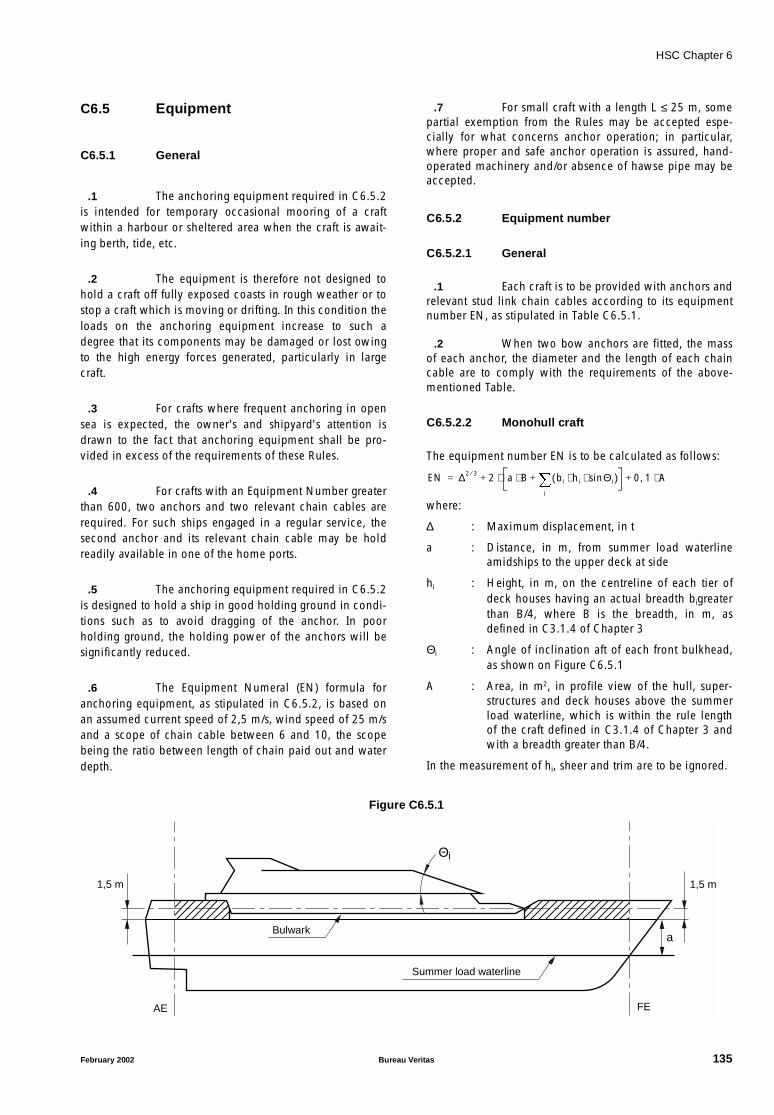
HSC Chapter 6
C6.5 Equipment
C6.5.1 General
.1 The anchoring equipment required in C6.5.2is intended for temporary occasional mooring of a craftwithin a harbour or sheltered area when the craft is await-ing berth, tide, etc.
.2 The equipment is therefore not designed tohold a craft off fully exposed coasts in rough weather or tostop a craft which is moving or drifting. In this condition theloads on the anchoring equipment increase to such adegree that its components may be damaged or lost owingto the high energy forces generated, particularly in largecraft.
.3 For crafts where frequent anchoring in opensea is expected, the owner's and shipyard's attention isdrawn to the fact that anchoring equipment shall be pro-vided in excess of the requirements of these Rules.
.4 For crafts with an Equipment Number greaterthan 600, two anchors and two relevant chain cables arerequired. For such ships engaged in a regular service, thesecond anchor and its relevant chain cable may be holdreadily available in one of the home ports.
.5 The anchoring equipment required in C6.5.2is designed to hold a ship in good holding ground in condi-tions such as to avoid dragging of the anchor. In poorholding ground, the holding power of the anchors will besignificantly reduced.
.6 The Equipment Numeral (EN) formula foranchoring equipment, as stipulated in C6.5.2, is based onan assumed current speed of 2,5 m/s, wind speed of 25 m/sand a scope of chain cable between 6 and 10, the scopebeing the ratio between length of chain paid out and waterdepth.
.7 For small craft with a length L ≤ 25 m, somepartial exemption from the Rules may be accepted espe-cially for what concerns anchor operation; in particular,where proper and safe anchor operation is assured, hand-operated machinery and/or absence of hawse pipe may beaccepted.
C6.5.2 Equipment number
C6.5.2.1 General
.1 Each craft is to be provided with anchors andrelevant stud link chain cables according to its equipmentnumber EN, as stipulated in Table C6.5.1.
.2 When two bow anchors are fitted, the massof each anchor, the diameter and the length of each chaincable are to comply with the requirements of the above-mentioned Table.
C6.5.2.2 Monohull craft
The equipment number EN is to be calculated as follows:
where:
∆ : Maximum displacement, in t
a : Distance, in m, from summer load waterlineamidships to the upper deck at side
hi : Height, in m, on the centreline of each tier ofdeck houses having an actual breadth bigreaterthan B/4, where B is the breadth, in m, asdefined in C3.1.4 of Chapter 3
Θi : Angle of inclination aft of each front bulkhead,as shown on Figure C6.5.1
A : Area, in m2, in profile view of the hull, super-structures and deck houses above the summerload waterline, which is within the rule lengthof the craft defined in C3.1.4 of Chapter 3 andwith a breadth greater than B/4.
In the measurement of hi, sheer and trim are to be ignored.
Figure C6.5.1
EN ∆2 3⁄ 2 a B⋅ bi hi Θisin⋅ ⋅( )i
+⋅ 0 1 A⋅,+ +=
1,5 m
Bulwark
Summer load waterline
a
1,5 m
AE FE
Θi
February 2002 Bureau Veritas 135
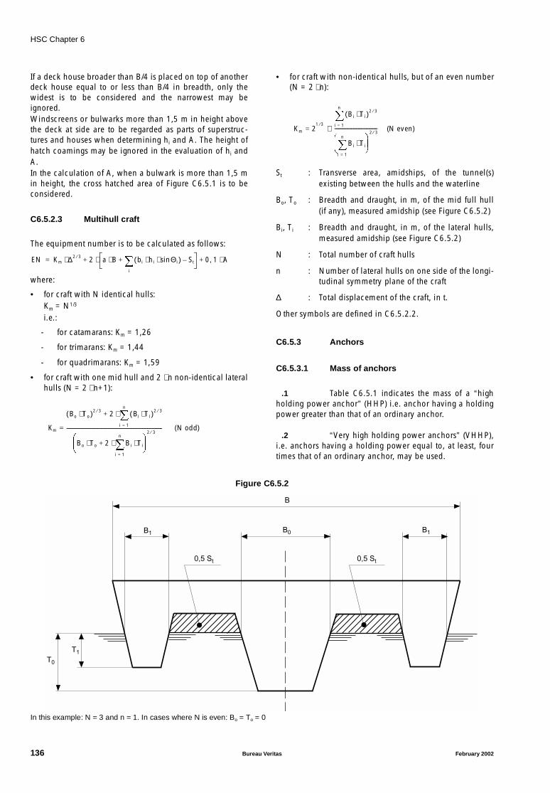
HSC Chapter 6
If a deck house broader than B/4 is placed on top of anotherdeck house equal to or less than B/4 in breadth, only thewidest is to be considered and the narrowest may beignored.Windscreens or bulwarks more than 1,5 m in height abovethe deck at side are to be regarded as parts of superstruc-tures and houses when determining hi and A. The height ofhatch coamings may be ignored in the evaluation of hi andA.In the calculation of A, when a bulwark is more than 1,5 min height, the cross hatched area of Figure C6.5.1 is to beconsidered.
C6.5.2.3 Multihull craft
The equipment number is to be calculated as follows:
where:
• for craft with N identical hulls:Km = N1/3
i.e.:
- for catamarans: Km = 1,26
- for trimarans: Km = 1,44
- for quadrimarans: Km = 1,59
• for craft with one mid hull and 2 ⋅ n non-identical lateralhulls (N = 2 ⋅ n+1):
• for craft with non-identical hulls, but of an even number(N = 2 ⋅ n):
St : Transverse area, amidships, of the tunnel(s)existing between the hulls and the waterline
Bo, To : Breadth and draught, in m, of the mid full hull(if any), measured amidship (see Figure C6.5.2)
Bi, Ti : Breadth and draught, in m, of the lateral hulls,measured amidship (see Figure C6.5.2)
N : Total number of craft hulls
n : Number of lateral hulls on one side of the longi-tudinal symmetry plane of the craft
∆ : Total displacement of the craft, in t.
Other symbols are defined in C6.5.2.2.
C6.5.3 Anchors
C6.5.3.1 Mass of anchors
.1 Table C6.5.1 indicates the mass of a “highholding power anchor” (HHP) i.e. anchor having a holdingpower greater than that of an ordinary anchor.
.2 “Very high holding power anchors” (VHHP),i.e. anchors having a holding power equal to, at least, fourtimes that of an ordinary anchor, may be used.
Figure C6.5.2
In this example: N = 3 and n = 1. In cases where N is even: Bo = To = 0
EN Km ∆2 3⁄⋅ 2 a B⋅ bi hi Θisin⋅ ⋅( )i
St–+⋅ 0 1 A⋅,+ +=
Km
Bo To⋅( )2 3⁄ 2 Bi Ti⋅( )2 3⁄
i 1=
n
⋅+
Bo To⋅ 2 Bi Ti⋅i 1=
n
⋅+
2 3⁄----------------------------------------------------------------------------= (N odd)
Km 21 3⁄
Bi Ti⋅( )2 3⁄
i 1=
n
Bi Ti⋅i 1=
n
2 3⁄----------------------------------⋅= (N even)
T0
T1
0,5 St 0,5 St
B0
B
B1B1
136 Bureau Veritas February 2002
HSC Chapter 6
.3 The actual mass of each anchor may varywithin (+7, −3) per cent of the value shown in the Table.
.4 The mass of a VHHP anchor is to be not lessthan 2/3 of the mass required for the HHP anchor itreplaces.
.5 Normally HHP or VHHP anchors are to beused. Possible use of ordinary anchors will be speciallyconsidered by the Society.
C6.5.3.2 Anchor design
.1 Anchors are to have appropriate shape andscantlings in compliance with Society requirements and areto be constructed in compliance with Society requirements.
.2 A high or very high holding power anchor isto be suitable for use on board without any prior adjustmentor special placement on the ground.
.3 For approval and/or acceptance as a high orvery high holding power anchor, the anchor is to have aholding power equal, respectively, to at least twice or fourtimes that of an ordinary stockless anchor of the same mass.
.4 Comparative tests on ordinary stocklessanchors are to be carried out at sea and are to provide satis-factory results on various types of seabeds.Alternatively sea trials by comparison with a previouslyapproved HHP anchor may be accepted as a basis forapproval.Such tests are to be carried out on anchors whose massesare, as far as possible, representative of the full range ofsizes proposed for the approval.At least two anchors of different sizes are to be tested. Themass of the greatest anchor to be approved is not to be inexcess of 10 times that of the maximum size tested and themass of the smallest is to be not less than 0,1 times that ofthe minimum size tested.Tests are normally to be carried out by means of a tug, but,alternatively, shore-based tests may be accepted.The length of the chain cable connected to the testedanchor, having a diameter appropriate to its mass, is to besuch that the pull acting on the shank remains practicallyhorizontal. For this purpose a scope of chain cable equal to10 is deemed normal; however lower values may beaccepted.Three tests are to be carried out for each anchor and type ofground.The pull is to be measured by means of a dynamometer;measurements based on the bollard pull against propeller'srevolutions per minute curve may be accepted instead ofdynamometer readings.Anchor stability and its ease of dragging are to be noteddown, whenever possible.
.5 Upon satisfactory outcome of the abovetests, the Society will issue a certificate declaring the com-pliance of high or very high holding power anchors with itsrelevant Rules.
C6.5.4 Chain cables
.1 Bow anchors are to be used in connectionwith stud link chain cables whose scantlings and steelgrades are to be in accordance with the requirements of theSociety.
.2 Normally grade Q2 or grade Q3 stud linkchain cables are to be used with HHP anchors. In case ofVHHP anchors, grade Q3 chain cables are to be used.
.3 Proposal for use of grade Q1 chain cablesconnected to ordinary anchors will be specially consideredby the Society.
.4 For craft with an Equipment NumberEN ≤ 205, studless short link chain cables may be used,provided that:
(a) steel grade of the studless chain is to be equivalent tothe steel grade of the stud chains it replaces, i.e., refer-ring to ISO standard 1834:
• Class M (4) [grade 400], i.e. grade SL2 as defined inPt D, Ch 4, Sec 1,[3] of the Rules for the Classifica-tion of Steel Ships, in lieu of grade Q2
• Class P (5) [grade 500], i.e. grade SL3 as defined inPt D, Ch 4, Sec 1, [3] of the Rules for the Classifica-tion of Steel Ships, in lieu of grade Q3
(b) equivalence in strength is to be based on proof load (noton breaking load)
(c) the studless chain cable meets the requirements of theSociety.
.5 The proof loads PL and breaking loads BL, inkN, required for the studless link chain cables are given bythe following formulae, where d, in mm, is the requireddiameter of grade Q2 and grade Q3 stud chain cables takenfrom Table C6.5.1:
• grade Q2:
PL2 = 9,807 ⋅ d2 ⋅ (44 − 0,08 ⋅ d) ⋅ 10−3
BL2 = 2 ⋅ PL2
• grade Q3:
PL3 = 13,73 ⋅ d2 ⋅ (44 − 0,08 ⋅ d) ⋅ 10−3
BL3 = 2 ⋅ PL3
.6 The method of manufacture of chain cablesand the characteristics of the steel used are to be approvedby the Society for each manufacturer. The material fromwhich chain cables are manufactured and the completedchain cables themselves are to be tested in accordance withthe appropriate requirements.
.7 Chain cables are to be made of unit lengths(“shots”) of 27,5 m minimum joined together by Dee or lug-less shackles.
February 2002 Bureau Veritas 137
HSC Chapter 6
C6.5.5 Steel wire ropes for anchors
.1 Steel wire ropes may be used as an alterna-tive to stud link chain cables required in Table C6.5.1 whenEN ≤ 500, provided that the following requirements arecomplied with.
.2 The length Lswr in m, of the steel wire rope isto be not less than:
• when EN ≤ 130:Lswr = Lch
• when 130 < EN ≤ 500:Lswr = Lch ⋅ (EN + 850) / 900
where Lch is the length of stud link chain cable required byTable C6.5.1.
.3 The effective breaking load of the steel wirerope is to be not less than the required breaking load of thechain cable it replaces.
.4 The breaking load, in kN, of the chain cablediameters shown between parentheses in Table C6.5.1 maybe derived from the following formulae:
• for grade Q2 chain cables:BL = 13,73 ⋅ d2 ⋅ (44 − 0,08 ⋅ d) ⋅ 10−3
• for grade Q3 chain cables:BL = 19,61 ⋅ d2 ⋅ (44 − 0,08 ⋅ d) ⋅ 10−3
where d is, in mm, the chain cable diameter taken fromTable C6.5.1 corresponding respectively to grade Q2 andgrade Q3 chain cables.
.5 A short length of chain cable having scant-lings complying with C6.5.4 is to be fitted between the steelwire rope and the bow anchor. The length of this chain partis to be not less than 12,50 m or the distance from theanchor in its stowed position to the windlass, whichever isthe lesser.
C6.5.6 Synthetic fibre ropes for anchors
.1 Synthetic fibre ropes may be used as an alter-native to stud link chain cables required in Table C6.5.1when EN ≤ 130, provided that the following requirementsare complied with.
.2 Fibre ropes are to be made of polyamide orother equivalent synthetic fibres, excluding polypropylene.
.3 The length Lsfr, in m, of the synthetic fibrerope is to be not less than:
• when EN ≤ 60:Lsfr = Lch
• when 60 < EN ≤ 130:Lsfr = Lch ⋅ (EN + 170)/200
where Lch is the length of stud link chain cable required byTable C6.5.1.
.4 The effective breaking load Ps, in kN, of thesynthetic fibre rope is to be not less than the followingvalue:Ps = 2,2 ⋅ B ⋅ L8/9
where BL, in kN, is the required breaking load of the chaincable replaced by the synthetic fibre rope (BL can be deter-mined by the formulae given in C6.5.5.4).
.5 A short length of chain cable complying withC6.5.5.5 is to be fitted between the synthetic fibre rope andthe bow anchor.
C6.5.7 Attachment pieces
.1 Both attachment pieces and connection fit-tings for chain cables are to be designed and constructed insuch a way as to offer the same strength as the chain cableand are to be tested in accordance with the appropriaterequirements.
C6.5.8 Arrangement of anchors and chaincables
.1 The bow anchors, connected to their ownchain cables, are to be so stowed as to always be ready foruse.
.2 Hawse pipes are to be of a suitable size andso arranged as to create, as far as possible, an easy lead forthe chain cables and efficient housing for the anchors.
.3 For this purpose, chafing lips of suitable formwith ample lay-up and radius adequate for the size of thechain cable are to be provided at the shell and deck. Theshell plating at the hawse pipes is to be reinforced asnecessary.
C6.5.9 Windlass
.1 The windlass is to be power driven and suita-ble for the size of chain cable, and is to have thecharacteristics stated below.
.2 The windlass is to be fitted in a suitable posi-tion in order to ensure an easy lead of the chain cable toand through the hawse pipe; the deck, at the windlass, is tobe suitably reinforced.
.3 The windlass is to be able to supply, for atleast 30 minutes, a continuous duty pull PC, in N, corre-sponding to the grade of the chain cables, given by thefollowing formulae:
• for grade Q2 chain cables:PC = 42,5 ⋅ d2
• for grade Q3 chain cables:PC = 47,5 ⋅ d2
where d is the stud link chain cable diameter of theintended steel grade, in mm.
138 Bureau Veritas February 2002
HSC Chapter 6
.4 The windlass unit prime mover is to providethe necessary temporary overload capacity for breaking outthe anchor.The temporary overload capacity or “short term pull” is tobe not less than 1,5 times the continuous duty pull PC for atleast two minutes.The speed in this overload period may be lower than thenominal speed specified in C6.5.9.5.
.5 The nominal speed of the chain cable whenhoisting the anchor and cable may be a mean speed onlyand is to be not less than 0,15 m/s.The speed is to be measured over two shots of chain cableduring the entire trip; the test is to commence with 3 shots(82,5 m) of chain fully submerged, or with the longest prac-ticable submerged chain length where the chain lengthdoes not allow 3 shots to be paid out.
.6 The windlass is to be provided with a brakehaving sufficient capacity to stop chain cable and anchorwhen paying out, even in the event of failure of the powersupply.
.7 Windlass and brake not combined with achain stopper have to be designed to withstand a pull of80% of the breaking load of the chain cable without anypermanent deformation of the stressed parts and withoutbrake slip.Windlass and brake combined with a chain stopper have tobe designed to withstand a pull of 45% of the breaking loadof the chain cable.
.8 The stresses on the parts of the windlass, itsframe and brake are to be below the yield point of the mate-rial used.The windlass, its frame and the brake are to be efficientlyanchored to the deck.
.9 Performance criteria and strength of wind-lasses are to be verified by means of workshop testingaccording to the Society Rules.
C6.5.10 Chain stopper
.1 A chain stopper is normally to be fittedbetween the windlass and the hawse pipe in order to relievethe windlass of the pull of the chain cable when the ship isat anchor.
.2 A chain stopper is to be capable of with-standing a pull of 80% of the breaking load of the chaincable; the deck at the chain stopper is to be suitablyreinforced.However, fitting of a chain stopper is not compulsory.
.3 Chain tensioners or lashing devices support-ing the weight of the anchor when housed in the anchorpocket are not to be considered as chain stoppers.
.4 Where the windlass is at a distance from thehawse pipe and no chain stopper is fitted, suitable arrange-ments are to be provided to lead the chain cable to thewindlass.
C6.5.11 Chain locker
.1 The chain locker is to be of a capacity ade-quate to stow all chain cable equipment and provide aneasy direct lead to the windlass.
.2 Where two anchor lines are fitted, the portand starboard chain cables are to be separated by a steelbulkhead in the locker.
.3 The inboard ends of chain cables are to besecured to the structure by a fastening able to withstand aforce not less than 15% nor more than 30% of the breakingload of the chain cable.In an emergency, the attachments are to be easily releasedfrom outside the chain locker.
.4 Where the chain locker is arranged aft of thecollision bulkhead, its boundary bulkheads are to be water-tight and a drainage system provided.
C6.5.12 Anchoring sea trials
.1 The anchoring sea trials are to be carried outon board in the presence of a Society surveyor.
.2 The test is to demonstrate that the windlasscomplies with the requirements given in C6.5.9.5.
.3 The brake is to be tested during loweringoperations.
February 2002 Bureau Veritas 139
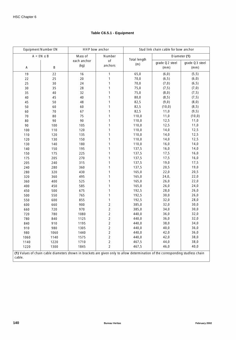
HSC Chapter 6
Table C6.5.1 - Equipment
Equipment Number EN HHP bow anchor Stud link chain cable for bow anchor
A < EN ≤ B Mass ofeach anchor
(kg)
Numberof
anchors
Total length(m)
Diameter (1)
grade Q2 steel(mm)
grade Q3 steel(mm)A B
192225303540455060708090
100110120130140150175205240280320360400450500550600660720780840910980
106011401220
2225303540455060708090
1001101201301401501752052402803203604004505005506006607207808409109801060114012201300
1620242832404860677590
105120135150180195225270315360430495525585675765855900970
10801125119513051440157517101845
11111111111111111111111111112222222222
65,070,070,075,075,080,082,582,582,5
110,0110,0110,0110,0110,0110,0110,0137,5137,5137,5137,5137,5165,0165,0165,0165,0192,5192,5192,5385,0385,0440,0440,0440,0440,0440,0440,0467,5467,5
(6,0)(6,5)(7,0)(7,5)(8,0)(8,5)(9,0)
(10,0)11,011,012,512,514,014,014,016,016,017,517,519,020,522,024,0,26,026,028,030,032,032,034,036,036,038,040,042,042,044,046,0
(5,5)(6,0)(6,5)(7,0)(7,5)(7,5)(8,0)(8,5)(9,5)(10,0)11,011,012,512,512,514,014,016,016,017,519,020,522,022,024,026,026,028,030,030,032,032,034,036,036,038,038,040,0
(1) Values of chain cable diameters shown in brackets are given only to allow determination of the corresponding studless chain cable.
140 Bureau Veritas February 2002
HSC Chapter 7
CHAPTER 7 FIRE SAFETY
Part A General
C7.0 Documents to be submitted
C7.0.1 The following drawings and documents areto be submitted, at least in triplicate for approval. The Soci-ety reserves its right to ask for supplementary copies, ifdeemed necessary in particular cases.
.1 Plan showing the arrangements of the firesubdivision, including doors and other closing means ofopenings in fire resisting divisions.
.2 Schematic plan concerning the natural andmechanical ventilation, with indication of location ofdampers and identification numbers of the fans servingeach craft section.
.3 Plan showing automatic fire detection sys-tems and manually operated call points, including firealarm systems.
.4 Plan relating to the water fire-fighting system(pumps, piping, etc.).
.5 Plan relating to the arrangement of fixed fireextinguishing systems.
.6 Constructional plans relevant to pressurevessels or bottles serving fixed fire extinguishing systemsmentioned under .5.
.7 Plans of pumping and drainage means for thewater delivered by fixed water-spraying fire extinguishingsystems.
.8 Plan relating to all other fire-fighting installa-tions, either fixed or portable.
C7.0.2 Further documentation may be required, ifdeemed necessary by the Society.
7.1 General Requirements
7.1.1 The following basic principles underlie theprovisions in this chapter and are embodied therein asappropriate, having regard to the category of craft and thepotential fire hazard involved:
.1 maintenance of the main functions andsafety systems of the craft, including propulsion and control,fire-detection, alarms and extinguishing capability of unaf-fected spaces, after fire in any one compartment on board;
.2 division of the public spaces for category Bcraft, in such a way that the occupants of any compartmentcan escape to an alternative safe area or compartment incase of fire;
.3 subdivision of the craft by fire-resistingboundaries;
.4 restricted use of combustible materials andmaterials generating smoke and toxic gases in a fire;
.5 detection, containment and extinction of anyfire in the space of origin;
.6 protection of means of escape and access forfire fighting; and
.7 immediate availability of fire-extinguishingappliances.
7.1.2 The requirements in this chapter are based inthe following conditions:
.1 Where a fire is detected, the crew immedi-ately puts into action the fire-fighting procedures, informsthe base port of the accident and prepares for the escape ofpassengers to alternative safe area or compartment, or, ifnecessary, for the evacuation of passengers.
.2 The use of fuel with a flashpoint below 43°Cis not recommended. However, fuel with a lower flashpoint,but not lower than 35°C, may be used in gas turbines onlysubject to compliance with the provisions specified in 7.5.1to 7.5.6.
.3 The repair and maintenance of the craft iscarried out in accordance with the requirements given inchapters 18 and 19 of this Code.
.4 Enclosed spaces having reduced lighting,such as cinemas, discotheques, and similar spaces are notpermitted.
February 2002 Bureau Veritas 141
HSC Chapter 7
.5 Passenger access to special category spacesand open ro-ro spaces is prohibited during the voyageexcept when accompanied by a crew member responsiblefor fire safety. Only authorised crew members shall be per-mitted to enter cargo spaces at sea.
C7.1.3 The following products are to be of approvedtype:
• Fire-restricting materials,
• Fire-resisting divisions (decks, bulkheads, doors),
• Penetrations of fire-resisting divisions for pipes, cables,ducts,
• Surface materials,
• Primary deck covering,
• Upholstery furniture,
• Bedding components,
• Curtains,
• Non-combustible materials,
• Oil pipes (other than steel or copper and copper alloys),
• Flexible pipes,
• Portable and mobile fire extinguishers,
• Nozzles for water spray systems or sprinkler systems,
• Fire-detection systems,
• Fire hoses and nozzles,
• Vapour detection systems,
• Non-sparking fans.
7.2 Definitions
7.2.1 “Fire-resisting divisions” are those divisionsformed by bulkheads and decks which comply with thefollowing:
.1 They shall be constructed of non-combusti-ble or fire-restricting materials which by insulation orinherent fire-resisting properties satisfy the requirements of7.2.1.2 to 7.2.1.6.
.2 They shall be suitably stiffened.
.3 They shall be so constructed as to be capableof preventing the passage of smoke and flame up to the endof the appropriate fire protection time.
.4 Where required they shall maintain load-car-rying capabilities up to the end of the appropriate fireprotection time.
.5 They shall have thermal properties such thatthe average temperature on the unexposed side will not risemore than 140°C above the original temperature, nor will
the temperature, at any one point, including any joint, risemore than 180°C above the original temperature during theappropriate fire protection time.
.6 A test of a prototype bulkhead or deck inaccordance with the Fire Test Procedures Code shall berequired to ensure that it meets the above requirements.
C7.2.1 With reference to 7.2.1.6 test procedures forfire-resisting divisions of high speed craft adopted by theOrganization by IMO Resolution MSC 45 (65) are to beapplied.
7.2.2 “Fire-restricting materials” are those materi-als which have properties complying with the Fire TestProcedures Code.
7.2.3 “Non-combustible material” is a materialwhich neither burns nor gives off flammable vapours in suf-ficient quantity for self-ignition when heated toapproximately 750°C, this being determined in accordancewith the Fire Test Procedures Code.
7.2.4 “A standard fire test” is one in which speci-mens of the relevant bulkheads, decks or otherconstructions are exposed in a test furnace by a specifiedtest method in accordance with the Fire Test ProceduresCode.
7.2.5 Where the words “steel or other equivalentmaterial” occur, “equivalent material” means any non-com-bustible material which, by itself or due to insulationprovided, has structural and integrity properties equivalentto steel at the end of the applicable exposure to the stand-ard fire test (e.g., aluminium alloy with appropriateinsulation).
7.2.6 “Low flame-spread” means that the surfacethus described will adequately restrict the spread of flame,this being determined in accordance with the Fire Test Pro-cedures Code.
7.2.7 “Smoke-tight” or “capable of preventing thepassage of smoke” means that a division made of non-com-bustible or fire-restricting materials is capable of preventingthe passage of smoke.
7.3 Classification of space use
7.3.1 For the purposes of classification of spaceuse in accordance with fire hazard risks, the followinggrouping shall apply:
142 Bureau Veritas February 2002

HSC Chapter 7
.1 “Areas of major fire hazard”, referred to intables 7.4-1 and 7.4-2 by A, include the following spaces:
- machinery spaces
- ro-ro spaces
- spaces containing dangerous goods
- special category spaces
- store-rooms containing flammable liquids
- galleys
- sales shops having a deck area of 50 m2 or greater andcontaining flammable liquids for sale
- trunks in direct communication with the above spaces.
.2 “Areas of moderate fire hazard”, referred toin tables 7.4-1 and 7.4-2 by B, include the following spaces:
- auxiliary machinery spaces, as defined in 1.4.4
- bond stores containing packaged beverages with alco-hol content not exceeding 24% by volume
- crew accommodation containing sleeping berths
- service spaces
- sales shops having a deck area of less than 50 m2 con-taining a limited amount of flammable liquids for saleand where no dedicated store is provided separately
- sales shops having a deck area of 50 m2 or greater notcontaining flammable liquids
- trunks in direct communication with the above spaces.
.3 “Areas of minor fire hazard”, referred to intables 7.4-1 and 7.4-2 by C, include the following spaces:
- auxiliary machinery spaces, as defined in 1.4.5
- cargo spaces
- fuel tank compartments
- public spaces
- tanks, voids and areas of little or no fire risk
- refreshment kiosks
- sales shops other than those specified in 7.3.1.1 and7.3.1.2
- corridors in passenger areas and stairway enclosures
- crew accommodation other than that mentioned in7.3.1.2
- trunks in direct communication with the above spaces.
.4 “Control stations”, referred to in tables 7.4-1and 7.4-2 by D, as defined in 1.4.15
.5 “Evacuation Stations and external escaperoutes”, referred to in tables 7.4-1 and 7.4-2 by E, includethe following areas:
- external stairs an open decks used for escape routes
- assembly stations, internal and external
- open deck spaces and enclosed promenades forminglifeboat and liferaft embarkation and lowering stations
- the craft's side to the waterline in the lightest seagoingcondition, superstructure and deckhouse sides situatedbelow and adjacent to the liferaft's and evacuationslide's embarkation areas.
.6 “Open Spaces” referred to in tables 7.4-1and 7.4-2 by F, include the following areas:
- open spaces locations other than evacuation stationsand external escape routes and control stations.
7.3.2 In approving structural fire protection details,the Administration shall have regard to the risk of heat trans-mission at intersections and terminal points of requiredthermal barriers.
7.4 Structural fire protection
7.4.1 Main structure
7.4.1.1 The requirements below apply to all craftirrespective of construction material. The structural fire pro-tection times for separating bulkheads and decks shall be inaccordance with tables 7.4-1 and 7.4.-2, and the structuralfire protection times are all based on providing protectionfor a period of 60 min as referred to in 4.8.1. If any otherlesser structural fire protection time is determined for cate-gory A craft and cargo craft by 4.8.1, then the times givenbelow in 7.4.2.2 and 7.4.2.3 may be amended pro rata. Inno case shall the structural fire protection time be less than30 min.
C7.4.1.1 Fire insulation may be omitted on upper sideof decks provided that a fixed water spraying system deliv-ering not less than 5 l/min/m² is installed.
7.4.1.2 In using tables 7.4-1 and 7.4-2, it shall benoted that the title of each category is intended to be typi-cal rather than restricted. For determining the appropriatefire integrity standards to be applied to boundaries betweenadjacent spaces, where there is doubt as to their classifica-tion for the purpose of this section, they shall be treated asspaces within the relevant category having the most strin-gent boundary requirement.
7.4.1.3 The hull, superstructure, structural bulk-heads, decks, deckhouses and pillars shall be constructed ofapproved non-combustible materials having adequate struc-tural properties. The use of other fire-restricting materialsmay be permitted provided the requirements of this chapterare complied with and the materials are in compliance withthe Fire Test Procedures Code.
February 2002 Bureau Veritas 143

HSC Chapter 7
Table 7.4.1 - Structural fire protection time for separating bulkheads and decks of passenger craft
Note: The figures on either side of the diagonal line represent the required structural fire protection time for the protection system on the relevant side of the division. When steel construction is used and two different structural fire protection times are required for a division in the table, only the greater one need be applied.
(1) The upper side of the decks of special category spaces, ro-ro spaces and open ro-ro spaces need not be insulated.(2) Where adjacent spaces are in the same alphabetical category and a note (2) appears, a bulkhead or deck between such spaces need not be fitted if deemed unnecessary by the Administration. For example, a bulkhead need not be required between two store-rooms. A bulkhead, is however, required between a machinery space and a special category space even though both spaces are in the same category.(3) No structural fire protection requirements; however, a smoke-tight division made of non-combustible or fire restricting material is required.(4) Control stations which are also auxiliary machinery spaces shall be provided with 30 min structural fire protection.(5) There are no special requirements for material or integrity of boundaries where only a dash appears in the table.(6) The fire protection time is 0 min and the time for prevention of passage of smoke and flame is 30 min as determined by the first 30 min of the standard fire test.(7) Fire resisting divisions need not comply with 7.2.1.5.(8) When steel construction is used, fire resisting divisions adjacent to void spaces need not comply with 7.2.1.5.(9) The fire protection time may be reduced to 0 min for those parts of open ro-ro spaces which are not essential parts of the craft’s main load bearing structure, where passengers have no access to them and crew need not have access to them during any emer-gency.(10) On category A craft, this value may be reduced to 0 min where the craft is provided with only a single public space (excluding lavatories) protected by a sprinkler system and adjacent to the operating compartment.
Areas of major fire hazard A
Areas of moderate fire hazard B
Areas of minor fire hazard C
Control stations D
Evacuation stations and escape routes E
Open spaces F
A B C D E F
60(1,2)
(1,2)
60(1)
3060
60 60 60 60
6030
30
30 30
30
(1,8)
(3)
(1) (1)
(3)
(3)
(3)
(3)
(3)
(3)
(3)
(3)
(3)
(3)
(3)(3)
(3)
(3)
(2)
(2)(3,4)
(3,4)
(3,4)
(3,4)
(3,4) (3,4)
(8,10)
(1,7,9)
(8)
-
-
-
-
-
-
-
144 Bureau Veritas February 2002
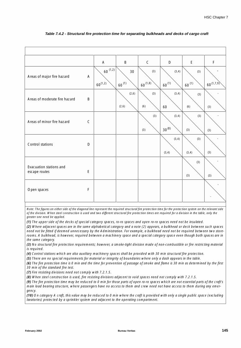
HSC Chapter 7
Table 7.4.2 - Structural fire protection time for separating bulkheads and decks of cargo craft
Note: The figures on either side of the diagonal line represent the required structural fire protection time for the protection system on the relevant side of the division. When steel construction is used and two different structural fire protection times are required for a division in the table, only the greater one need be applied.
(1) The upper side of the decks of special category spaces, ro-ro spaces and open ro-ro spaces need not be insulated.(2) Where adjacent spaces are in the same alphabetical category and a note (2) appears, a bulkhead or deck between such spaces need not be fitted if deemed unnecessary by the Administration. For example, a bulkhead need not be required between two store-rooms. A bulkhead, is however, required between a machinery space and a special category space even though both spaces are in the same category.(3) No structural fire protection requirements; however, a smoke-tight division made of non-combustible or fire restricting material is required.(4) Control stations which are also auxiliary machinery spaces shall be provided with 30 min structural fire protection.(5) There are no special requirements for material or integrity of boundaries where only a dash appears in the table.(6) The fire protection time is 0 min and the time for prevention of passage of smoke and flame is 30 min as determined by the first 30 min of the standard fire test.(7) Fire resisting divisions need not comply with 7.2.1.5.(8) When steel construction is used, fire resisting divisions adjacent to void spaces need not comply with 7.2.1.5.(9) The fire protection time may be reduced to 0 min for those parts of open ro-ro spaces which are not essential parts of the craft’s main load bearing structure, where passengers have no access to them and crew need not have access to them during any emer-gency.(10) On category A craft, this value may be reduced to 0 min where the craft is provided with only a single public space (excluding lavatories) protected by a sprinkler system and adjacent to the operating compartment.
Areas of major fire hazard A
Areas of moderate fire hazard B
Areas of minor fire hazard C
Control stations D
Evacuation stations and escape routes E
Open spaces F
A B C D E F
60(1,2)
(1,2)
60(1)
3060
60 60 60 60
60
30
(1,8)
(3)
(1) (1)
(3)
(3)
(3)
(3)
(3)
(3)
(3)
(3)
(3)
(3)
(3)(3)
(3)
(3)
(2,6)
(3,4)
(3,4)
(3,4)
(3,4)
(3,4) (3,4)
(8)
(1,7,9)
(6)
-
-
-
-
-
-
-
(2,6)
(6)
February 2002 Bureau Veritas 145
HSC Chapter 7
7.4.2 Fire-resisting divisions
7.4.2.1 Areas of major and moderate fire hazardshall be enclosed by fire-resisting divisions complying withthe requirements of 7.2.1 except where the omission of anysuch division would not affect the safety of the craft. Theserequirements need not apply to those parts of the structurein contact with water at the lightweight condition, but dueregard shall be given to the effect of temperature of hull incontact with water and heat transfer from any uninsulatedstructure in contact with water to insulated structure abovethe water.
7.4.2.2 Fire-resisting bulkheads and decks shall beconstructed to resist exposure to the standard fire test for aperiod of 30 min for areas of moderate fire hazard and 60minutes for areas of major fire hazard except as provided in7.4.1.1.
7.4.2.3 Main load-carrying structures within areas ofmajor fire hazard and areas of moderate fire hazard andstructures supporting control stations shall be arranged todistribute load such that there will be no collapse of theconstruction of the hull and superstructure when it isexposed to fire for the appropriate fire protection time. Theload-carrying structure shall also comply with the require-ments of 7.4.2.4 and 7.4.2.5.
7.4.2.4 If the structures specified in 7.4.2.3 are madeof aluminium alloy their installation shall be such that thetemperature of the core does not rise more than 200°Cabove the ambient temperature in accordance with thetimes in 7.4.1.1 and 7.4.2.2.
7.4.2.5 If the structures specified in 7.4.2.3 are madeof combustible material, their insulation shall be such thattheir temperatures will not rise to a level where deteriora-tion of the construction will occur during the exposure tothe standard fire test in accordance with the Fire Test Proce-dures Code to such an extent that the load-carryingcapability, in accordance with the times in 7.4.1.1 and7.4.2.3, will be impaired.
7.4.2.6 The construction of all doors, and doorframes in fire-resisting divisions, with the means of securingthem when closed, shall provide resistance to fire as well asto the passage of smoke and flame equivalent to that of thebulkheads in which they are situated. Watertight doors ofsteel need not be insulated. Also, where a fire-resisting divi-sion is penetrated by pipes, ducts, electrical cables etc.,arrangements shall be made to ensure that the fire-resistingintegrity of the division is not impaired, and necessary test-ing shall be carried out in accordance with the Fire TestProcedures Code.
7.4.3 Restricted use of combustible materials
7.4.3.1 All separating divisions, ceilings or linings ifnot a fire resisting division, shall be of non-combustible orfire restricting materials. Draught stops shall be of non-com-bustible or fire-restricting material.
7.4.3.2 Where insulation is installed in areas inwhich it could come into contact with any flammable fluidsor their vapours, its surface shall be impermeable to suchflammable fluids of vapours.
7.4.3.3 Furniture and furnishings in public spacesand crew accommodation shall comply with the followingstandards:
.1 all case furniture is constructed entirely ofapproved non-combustible or fire-restricting materials,except that a combustible veneer with a calorific value notexceeding 45 MJ/m2 may be used on the exposed surface ofsuch articles;
.2 all other furniture such as chairs, sofas andtables, is constructed with frames of non-combustible orfire-restricting materials;
.3 all draperies, curtains and other suspendedtextile materials have qualities of resistance to the propaga-tion of flame, this being determined in accordance with theFire Test Procedures Code;
.4 all upholstered furniture has qualities ofresistance to the ignition and propagation of flame, thisbeing determined in accordance with the Fire Test Proce-dures Code;
.5 all bedding components have qualities ofresistance to the ignition and propagation of flame, thisbeing determined in accordance with the Fire Test Proce-dures Code; and
.6 all deck finish materials comply with the FireTest Procedures Code.
C7.4.3.3 Requirement 7.4.3.3.1 is applicable to furni-ture such as desks, wardrobes, dressing tables, bureaux anddressers.
7.4.3.4 The following surfaces shall, as a minimumstandard, be constructed of materials having low flame-spread characteristics:
.1 exposed surfaces in corridors and stairwayenclosures, and of bulkheads (including windows), walland ceiling linings in all public spaces, crew accommoda-tion, service spaces, control stations and internal assemblyand evacuation stations;
146 Bureau Veritas February 2002

HSC Chapter 7
.2 surfaces in concealed or inaccessible spacesin corridors and stairway enclosures, public spaces, crewaccommodation, service spaces, control stations and inter-nal assembly and evacuation stations.
7.4.3.5 Any thermal and acoustic insulation shall beof non-combustible or of fire-restricting material. Vapourbarriers and adhesives used in conjunction with insulation,as well as insulation of pipe fittings for cold service systemsneed not be non-combustible or fire-restricting, but theyshall be kept to the minimum quantity practicable and theirexposed surfaces shall have low flame spread characteris-tics.
7.4.3.6 Exposed surfaces in corridors and stairwayenclosures, and of bulkheads (including windows), walland ceiling linings, in all public spaces, crew accommoda-tion, service spaces, control stations and internal assemblyand evacuation stations shall be constructed of materialswhich, when exposed to fire, are not capable of producingexcessive quantities of smoke or toxic products, this beingdetermined in accordance with the Fire Test ProceduresCode.
7.4.3.7 Void compartments, where low-density com-bustible materials are used to provide buoyancy, shall beprotected from adjacent fire hazard areas by fire-resistingdivisions, in accordance with tables 7.4-1 and 7.4-2. Also,the space and closures to it shall be gastight but it shall beventilated to atmosphere.
7.4.3.8 In compartments where smoking is allowed,suitable non-combustible ash containers shall be provided.In compartments where smoking is not allowed, adequatenotices shall be displayed.
7.4.3.9 The exhaust gas pipes shall be arranged sothat the risk of fire is kept to a minimum. To this effect, theexhaust system shall be insulated and all compartments andstructures which are contiguous with the exhaust system, orthose which may be affected by increased temperaturescaused by waste gases in normal operation or in an emer-gency, shall be constructed of non-combustible material orbe shielded and insulated with non-combustible material toprotect from high temperatures.
7.4.3.10 The design and arrangement of the exhaustmanifolds or pipes shall be such as to ensure the safe dis-charge of exhaust gases.
7.4.4 Arrangement
7.4.4.1 Internal stairways connecting only two decksneed only be enclosed at one deck by means of divisionsand self-closing doors having the structural fire protectiontime as required by tables 7.4-1 and 7.4-2 for divisions sep-arating those areas which each stairway serves. Stairwaysmay be fitted in the open in a public space, provided theylie wholly within such public space.
7.4.4.2 Lift trunks shall be so fitted as to prevent thepassage of smoke and flame from one deck to another andshall be provided with means of closing so as to permit thecontrol of draught and smoke.
7.4.4.3 In public spaces, crew accommodation,service spaces, control stations, corridors and stairways, airspaces enclosed behind ceilings, panelling or linings shallbe suitably divided by close-fitting draught stops not morethan 14 m apart. On category A craft provided with only asingle public space, draught stops need not be provided insuch public space.
7.5 Fuel and other flammable fluidtanks and systems
7.5.1 Tanks containing fuel and other flammablefluids shall be separated from passenger, crew, and baggagecompartments by vapour-proof enclosures or cofferdamswhich are suitably ventilated and drained.
7.5.2 Fuel oil tanks shall not be located in, beformed by any part of the structural boundary of, areas ofmajor fire hazard. However, flammable fluids of a flashpointnot less than 60°C may be located within such areas pro-vided the tanks are made of steel or other equivalentmaterial.
C7.5.2 Integral or independent fuel tanks made ofaluminium alloys, GRP or equivalent may be located withinmajor fire hazard areas when they are insulated for 60 min-utes fire integrity. The same insulation standard is requiredfor bulkheads or decks separating oil fuel tanks from majorfire hazard areas.
7.5.3 Every fuel oil pipe which, if damaged, wouldallow oil to escape from a storage, settling or daily servicetank shall be fitted with a cock or valve directly on the tankcapable of being closed from a position outside the spaceconcerned in the event of a fire occurring in the space inwhich such tanks are situated.
7.5.4 Pipes, valves and couplings conveying flam-mable fluids shall be of steel or such alternative materialsatisfactory to a standard, in respect of strength and fireintegrity having regard to the service pressure and thespaces in which they are installed (see note). Whereverpracticable, the use of flexible pipes shall be avoided.
Note: Refer to the Guidelines for the Application of Plastic Pipes onShips, adopted by the Organization by resolution A.753(18).
February 2002 Bureau Veritas 147
HSC Chapter 7
7.5.5 Pipes, valves and couplings conveying flam-mable fluids shall be arranged as far from hot surfaces or airintakes of engine installations, electrical appliances andother potential sources of ignition as is practicable and belocated or shielded so that the likelihood of fluid leakagecoming into contact with such sources of ignition is kept toa minimum.
7.5.6 Fuel with a flash point below 35°C shall notbe used. In every craft in which fuel with a flashpoint below43°C is used, the arrangements for the storage, distributionand utilization of the fuel shall be such that, having regardto the hazard of fire and explosion which the use of suchfuel may entail, the safety of the craft and of persons onboard is preserved. The arrangements shall comply, in addi-tion to the requirements of 7.5.1 to 7.5.5, with the followingprovisions:
.1 tanks for the storage of such fuel shall belocated outside any machinery space and at a distance ofnot less than 760 mm inboard from the shell side and bot-tom plating, and from decks and bulkheads;
.2 arrangements shall be made to prevent over-pressure in any fuel tank or in any part of the oil fuel system,including the filling pipes. Any relief valves and air or over-flow pipes shall discharge to a position which, in theopinion of the Administration, is safe;
.3 the spaces in which fuel tanks are locatedshall be mechanically ventilated, using exhaust fans provid-ing not less than six air changes per hour. The fans shall besuch as to avoid the possibility of ignition of flammable gas-air mixtures. Suitable wire mesh guards shall be fitted overinlet and outlet ventilation openings. The outlets for suchexhausts shall discharge to a position which, in the opinionof the Administration is safe. “No Smoking” signs shall beposted at the entrance to such spaces;
.4 earthed electrical distribution systems shallnot be used, with the exception of earthed intrinsically safecircuits;
.5 suitable certified safe type electrical equip-ment be used in all spaces where fuel leakage could occur,including the ventilation system (see note). Only electricalequipment and fittings essential for operational purposesshall be fitted in such spaces;
Note: Refer to the Recommendations published by the Interna-tional Electrotechnical Commission and, in particular, publication60092–Electrical Installations in Ships.
.6 a fixed vapour-detection system shall beinstalled in each space through which fuel lines pass, withalarms provided at the continuously manned controlstation;
.7 every fuel tanks shall, where necessary, beprovided with “savealls” or gutters which would catch anyfuel which may leak from such tank;
.8 safe and efficient means of ascertaining theamount of fuel contained in any tank shall be provided.Sounding pipes shall not terminate in any space where therisk of ignition of spillage from the sounding pipe mightarise. In particular, they shall not terminate in passenger orcrew spaces. The use of cylindrical gauge glasses is prohib-ited, except for cargo craft where the use of oil-level gaugeswith flat glasses and self-closing valves between the gaugesand fuel tanks may be permitted by the Administration.Other means of ascertaining the amount of fuel containedin any tank may be permitted if such means do not requirepenetration below the top of the tank, and providing theirfailure or overfilling of the tank will not permit the release offuel;
.9 during bunkering operations, no passengershall be on board the craft or in the vicinity of the bunkeringstation, and adequate “No Smoking” and “No NakedLights” signs shall be posted. Vessel-to-shore fuel connec-tions shall be of closed type and suitably grounded duringbunkering operations;
.10 the provision of fire detection and extinguish-ing systems in spaces where non-integral fuel tanks arelocated shall be in accordance with requirements of 7.7.1to 7.7.3; and
.11 refuelling of the craft shall be done at theapproved refuelling facilities, detailed in the route opera-tional manual, at which the following fire appliances areprovided:
.11.1 a suitable foam applicator system consisting ofmonitors and foam-making branch pipes capa-ble of delivering foam solution at a rate of notless than 500l/m for not less than 10 min;
.11.2 dry powder extinguishers of total capacity notless than 50 kg; and
.11.3 carbon dioxide extinguishers of total capacitynot less than 16 kg.
C7.5.6 With reference to 7.5.6.3, fans are to be of anon-sparking type in accordance with Society Rules.
7.6 Ventilation
7.6.1 The main inlets and outlets of all ventilationsystems shall be capable of being closed from outside thespaces being ventilated. In addition, such openings to areasof major fire hazard shall be capable of being closed from acontinuously manned control station.
148 Bureau Veritas February 2002

HSC Chapter 7
7.6.2 All ventilation fans shall be capable of beingstopped from outside the spaces which they serve, andfrom outside the spaces in which they are installed. Ventila-tion fans serving areas of major fire hazard shall be capableof being operated from a continuously manned controlstation.
The means provided for stopping the power ventilation tothe machinery space shall be separated from the meansprovided for stopping ventilation of other spaces.
7.6.3 Areas of major fire hazard and spaces servingas assembly stations shall have independent ventilation sys-tems and ventilation ducts. Ventilation ducts for areas ofmajor fire hazard shall not pass through other spaces, unlessthey are contained within a trunk or in an extended machin-ery space or casing insulated in accordance with tables 7.4-1 and 7.4-2; ventilation ducts of other spaces shall not passthrough areas of major fire hazard. Ventilation outlets fromareas of major fire hazard shall not terminate within a dis-tance of 1 m from any control station, evacuation station orexternal escape route. In addition, exhaust ducts from galleyranges shall be fitted with:
.1 a grease trap readily removable for cleaningunless an alternative approved grease removal system isfitted;
.2 a fire damper located in the lower end of theduct which is automatically-and remotely operated, and inaddition a remotely operated fire damper located in theupper end of the duct;
.3 a fixed means for extinguishing a fire withinthe duct;
.4 remote control arrangements for shutting offthe exhaust fans and supply fans, for operating the firedampers mentioned in .2 and for operating the fire-extin-guishing system, which shall be placed in a position close tothe entrance to the galley. Where a multi-branch system isinstalled, means shall be provided to close all branchesexhausting through the same main duct before an extin-guishing medium is released into the system; and
.5 suitably located hatches for inspection andcleaning.
7.6.4 Where a ventilation duct passes through afire-resisting division, a fail safe automatic closing firedamper shall be fitted adjacent to the division. The ductbetween the division and the damper shall be of steel orother equivalent material and insulated to the same stand-ard as required for the fire resisting division. The fire dampermay be omitted where ducts pass through spaces sur-rounded by fire-resisting divisions without serving thosespaces providing that the duct has the same structural fireprotection time as the divisions it penetrates. Where a venti-lation duct passes through a smoke-tight division, a smokedamper shall be fitted at the penetration unless the ductwhich passes through the space does not serve that space.
7.6.5 Where ventilation systems penetrate decks,the arrangements shall be such that the effectiveness of thedeck in resisting fire is not thereby impaired and precau-tions shall be taken to reduce the likelihood of smoke andhot gases passing from one between-deck space to anotherthrough the system.
7.6.6 All dampers fitted on fire-resisting or smoke-tight divisions shall also be capable of being manuallyclosed from each side of the division in which they are fit-ted, except for those dampers fitted on ducts serving spacenot normally manned such as stores and toilets that may bemanually operated only from outside the served spaces. Alldampers shall also be capable of being remotely closedfrom the continuously manned control station.
7.6.7 Ducts shall be made of non-combustible orfire restricting material. Short ducts, however, may be ofcombustible materials subject to the following conditions:
.1 their cross-section does not exceed 0.02 m2;
.2 their length does not exceed 2 m;
.3 they may only be used at the terminal end ofthe ventilation system;
.4 they shall not be situated less than 600 mmfrom an opening in a fire-resisting or fire-restricting division;and
.5 their surfaces have low flame spreadcharacteristics.
7.7 Fire detection and extinguishingsystems
7.7.1 Fire detection systems
Areas of major and moderate fire hazard and otherenclosed spaces not regularly occupied within publicspaces and crew accommodation, such as toilets, stairwayenclosures, corridors and escape routes shall be providedwith an approved automatic smoke detection system andmanually operated call points complying with the require-ments of 7.7.1.1 and 7.7.1.3 to indicate at the controlstation the location of outbreak of a fire in all normal operat-ing conditions of the installations. Detectors operated byheat instead of smoke may be installed in galleys. Main pro-pulsion machinery room(s) shall in addition have detectorssensing other than smoke and be supervised by TV camerasmonitored from the operating compartment. Manuallyoperated call points shall be installed throughout the publicspaces, crew accommodation, corridors and stairwayenclosures, service spaces and where necessary control sta-tions. One manually operated call point shall be located ateach exit from these spaces and from areas of major firehazard.
February 2002 Bureau Veritas 149
HSC Chapter 7
7.7.1.1 General requirements
.1 Any required fixed fire-detection and firealarm system with manually operated call points shall becapable of immediate operation at all times.
.2 Power supplies and electric circuits neces-sary for the operation of the system shall be monitored forloss of power or fault conditions as appropriate. Occurrenceof a fault condition shall initiate a visual and audible faultsignal at the control panel which shall be distinct from a firesignal.
.3 There shall be not less than two sources ofpower supply for the electrical equipment used in the oper-ation of the fixed fire-detection and fire alarm system, one ofwhich shall be an emergency source. The supply shall beprovided by separate feeders reserved solely for that pur-pose. Such feeders shall run to an automatic change-overswitch situated in or adjacent to the control panel for thefire-detection system.
.4 Detectors and manually operated call pointsshall be grouped into sections. The activation of any detec-tor or manually operated call point shall initiate a visual andaudible fire signal at the control panel and indicating units.If the signals have not received attention within two minutesan audible alarm shall be automatically sounded through-out the crew accommodation and service spaces, controlstations and machinery spaces. There shall be no time delayfor the audible alarms in crew accommodation areas whenall the control stations are unattended. The alarm soundersystem need not be an integral part of the detection system.
.5 The control panel shall be located in theoperating compartment or in the main fire control station.
.6 Indicating units shall, as a minimum, denotethe section in which a detector or manually operated callpoint has operated. At least one unit shall be so located thatit is easily accessible to responsible members of the crew atall times, when at sea or in port, except when the craft is outof service. One indicating unit shall be located in the oper-ating compartment if the control panel is located in thespace other than the operating compartment.
.7 Clear information shall be displayed on oradjacent to each indicating unit about the spaces coveredand the location of the sections.
.8 Where the fire-detection system does notinclude means of remotely identifying each detector individ-ually, no section covering more than one deck within publicspaces, crew accommodation, corridors, service spaces andcontrol stations shall normally be permitted except a sectionwhich covers an enclosed stairway. In order to avoid delayin identifying the source of fire, the number of enclosedspaces included in each section shall be limited as deter-mined by the Administration. In no case shall more than 50enclosed spaces be permitted in any section. If the detec-tion system is fitted with remotely and individuallyidentifiable fire detectors, the sections may cover severaldecks and serve any number of enclosed spaces.
.9 In passenger craft, if there is no fire-detectionsystem capable of remotely and individually identifyingeach detector, a section of detectors shall not serve spaceson both sides of the craft nor on more than one deck andneither shall it be situated in more than one zone accordingto 7.11.1 except that the Administration, if it is satisfied thatthe protection of the craft against fire will not thereby bereduced, may permit such a section of detectors to serveboth sides of the craft and more than one deck. In passen-ger craft fitted with individually identifiable fire detectors, asection may serve spaces on both sides of the craft and onseveral decks.
.10 A section of fire detectors which covers acontrol station, a service space, a public space, crewaccommodation, corridor or stairway enclosure shall notinclude a machinery space of major fire hazard.
.11 Detectors shall be operated by heat, smokeor other products of combustion, flame, or any combinationof these factors. Detectors operated by other factors indica-tive of incipient fires may be considered by theAdministration provided that they are no less sensitive thansuch detectors. Flame detectors shall only be used in addi-tion to smoke or heat detectors.
.12 Suitable instructions and component sparesfor testing and maintenance shall be provided.
.13 The function of the detection system shall beperiodically tested by means of equipment producing hotair at the appropriate temperature, or smoke or aerosol par-ticles having the appropriate range of density or particlesize, or other phenomena associated with incipient fires towhich the detector is designed to respond. All detectorsshall be of a type such that they can be tested for correctoperation and restored to normal surveillance without therenewal of any component.
.14 The fire-detection system shall not be usedfor any other purpose, except that closing of fire doors andsimilar functions may be permitted at the control panel.
.15 Fire-detection systems with a zone addressidentification capability shall be so arranged that:
.1 a loop cannot be damaged at more than onepoint by a fire;
.2 means are provided to ensure that any fault(e.g., power break; short circuit; earth) occur-ring in the loop shall render the whole loopineffective;
.3 all arrangements are made to enable the initialconfiguration of the system to be restored in theevent of failure (electrical, electronic, infor-matic); and
.4 the first initiated fire alarm shall not prevent anyother detector to initiate further fire alarms.
150 Bureau Veritas February 2002

HSC Chapter 7
7.7.1.2 Installation requirements
.1 In addition to 7.7.1, manually operated callpoints shall be readily accessible in the corridors of eachdeck such that no part of the corridor is more than 20 mfrom a manually operated call point.
.2 Where a fixed fire-detection and fire alarmsystem is required for the protection of spaces other thanstairways, corridors and escape routes, at least one detectorcomplying with 7.7.1.1.11 shall be installed in each suchspace.
.3 Detectors shall be located for optimum per-formance. Positions near beams and ventilation ducts orother positions where patterns of air flow could adverselyaffect performance and positions where impact or physicaldamage is likely shall be avoided. In general, detectorswhich are located on the overhead shall be a minimum dis-tance of 0.5 m away from bulkheads.
.4 The maximum spacing of detectors shall bein accordance with Table 7.7.1.2.4.The Administration may require or permit other spacingsbased upon test data which demonstrate the characteristicsof the detectors.
Table 7.7.1.2.4
.5 Electrical wiring which forms parts of the sys-tem shall be so arranged as to avoid machinery spaces ofmajor fire hazard, and other enclosed spaces of major firehazard except, where it is necessary, to provide for firedetection or fire alarm in such spaces or to connect to theappropriate power supply.
7.7.1.3 Design requirements
.1 The system and equipment shall be suitablydesigned to withstand supply voltage variation and tran-sients, ambient temperature changes, vibration, humidity,shock, impact and corrosion normally encountered in ships.
.2 Smoke detectors shall be certified to operatebefore the smoke density exceeds 12.5% obscuration permetre, but not until the smoke density exceeds 2% obscura-tion per metre. Smoke detectors to be installed in otherspaces shall operate within sensitivity limits to the satisfac-tion of the Administration having regard to the avoidance ofdetector insensitivity or over-sensitivity.
.3 Heat detectors shall be certified to operatebefore the temperature exceeds 78°C but not until the tem-perature exceeds 54°C, when the temperature is raised to
those limits at a rate less than 1°C per minute. At higherrates of temperature rise, the heat detector shall operatewithin temperature limits having regard to the avoidance todetector insensitivity or over-sensitivity.
.4 At the discretion of the Administration, thepermissible temperature of operation of heat detectors maybe increased to 30°C above the maximum deckhead tem-perature in drying rooms and similar spaces of a normalhigh ambient temperature.
.5 Flame detectors corresponding to 7.7.1.1.11shall have a sensitivity sufficient to determine flame againstan illuminated space background and a false signal identifi-cation system.
7.7.2 Fire detection for periodicallyunattended machinery spaces
A fixed fire-detection and fire alarm system for periodicallyunattended machinery spaces shall comply with the follow-ing requirements:
.1 The fire-detection system shall be sodesigned and the detectors so positioned as to detect rap-idly the onset of fire in any part of those spaces and underany normal conditions of operation of the machinery andvariations of ventilation as required by the possible range ofambient temperatures. Except in spaces of restricted heightand where their use is specially appropriate, detection sys-tems using only thermal detectors shall not be permitted.The detection system shall initiate audible and visual alarmsdistinct in both respects from the alarms of any other systemnot indicating fire, in sufficient places to ensure that thealarms are heard and observed on the navigating bridge andby a responsible engineer officer. When the operating com-partment is unmanned the alarm shall sound in a placewhere a responsible member of the crew is on duty.
.2 After installation, the system shall be testedunder varying conditions of engine operation andventilation.
7.7.3 Fixed fire-extinguishing systems
7.7.3.1 Areas of major fire hazard shall be protectedby an approved fixed fire-extinguishing system operablefrom the control position which is adequate for the fire haz-ard that may exist. The system shall comply with 7.7.3.2and 7.7.3.3 or with alternative arrangements approved bythe Administration taking into account the recommenda-tions and guidelines developed by the Organization and becapable of local manual control and remote control fromthe continuously manned control stations.
Note: Refer to MSC/Circ.668 –Alternative arrangements for halonfire-extinguishing systems in machinery spaces and pump-rooms,and amendments thereto contained in MSC/Circ.728 –Revised testmethod for equivalent water-based fire extinguishing systems formachinery spaces of category A and cargo pump-rooms contained
Type of detector
Maximum floor area
per detector
Maximumdistance apart
between centre
Maximumdistance away
from bulkheads
Heat 37 m2 9 m 4.5 m
Smoke 74 m2 11 m 5.5 m
February 2002 Bureau Veritas 151

HSC Chapter 7
in MSC/Circ.668; and to MSC/Circ.848 –Revised Guidelines for theapproval of equivalent fixed gas fire-extinguishing systems, asreferred to in SOLAS 74, for machinery spaces and cargo pump-rooms.
7.7.3.2 General requirements
.1 In all craft where gas is used as the extin-guishing medium, the quantity of gas shall be sufficient toprovide two independent discharges. The second dischargeinto the space shall only be activated manually from a posi-tion outside the space being protected. Where the spacehas a local fire-suppression system installed, based on theguidelines developed by the Organization, to protect fueloil, lubricating oil and hydraulic oil located near exhaustmanifolds, turbo chargers or similar heated surfaces onmain and auxiliary internal combustion engines, a seconddischarge need not be required.
Note: Refer to the Guidelines for the approval of water-based localapplication of fixed fire-suppression systems, to be developed bythe Organization.
.2 The use of a fire-extinguishing mediumwhich, in the opinion of the Administration, either by itselfor under expected conditions of use will adversely affect theearth's ozone layer and/or gives off toxic gases in suchquantities as to endanger persons shall not be permitted.
.3 The necessary pipes for conveying fire-extin-guishing medium into protected spaces shall be providedwith control valves so marked as to indicate clearly thespaces to which the pipes are led. Non-return valves shallbe installed in discharge lines between cylinders and mani-folds. Suitable provision shall be made to preventinadvertent admission of the medium to any space.
.4 The piping for the distribution of fire-extin-guishing medium shall be arranged and discharge nozzlesso positioned that a uniform distribution of medium isobtained.
.5 Means shall be provided to close all openingswhich may admit air to, or allow gas to escape from, a pro-tected space.
.6 Where the volume of free air contained in airreceivers in any space is such that, if released in such spacein the event of fire, such release of air within that spacewould seriously affect the efficiency of the fixed fire-extin-guishing system, the Administration shall require theprovision of an additional quantity of fire-extinguishingmedium.
.7 Means shall be provided for automaticallygiving audible warning of the release of fire-extinguishingmedium into any space in which personnel normally workor to which they have access. The alarm shall operate for asuitable period before the medium is released, but not lessthan 20 s. Visible alarm shall be arranged in addition to theaudible alarm.
.8 The means of control of any fixed gas fire-extinguishing system shall be readily accessible and simpleto operate and shall be grouped together in as few locationsas possible at positions not likely to be cut off by a fire in aprotected space. At each location there shall be clearinstructions relating to the operation of the system, havingregard to the safety of personnel.
.9 Automatic release of fire-extinguishingmedium shall not be permitted.
.10 Where the quantity of extinguishing mediumis required to protect more than one space, the quantity ofmedium available need not be more than the largest quan-tity required for any one space so protected.
.11 Pressure containers required for the storageof fire-extinguishing medium shall be located outside pro-tected spaces in accordance with 7.7.3.2.14. Pressurecontainers may be located inside the space to be protectedif in the event of accidental release persons will not beendangered.
.12 Means shall be provided for the crew tosafely check the quantity of medium in the containers.
.13 Containers for the storage of fire-extinguish-ing medium and associated pressure components shall bedesigned having regard to their locations and maximumambient temperatures expected in service.
.14 When the fire-extinguishing medium is storedoutside a protected space, it shall be stored in a roomwhich shall be situated in a safe and readily accessible posi-tion and shall be effectively ventilated. Any entrance to sucha storage room shall preferably be from the open deck andin any case shall be independent of the protected space.Access doors shall open outwards, and bulkheads anddecks including doors and other means of closing any open-ing therein, which form the boundaries between suchrooms and adjoining enclosed spaces, shall be gas tight.Such storage rooms shall be treated as control rooms.
.15 Spare parts for the system shall be stored onboard or at a base port.
.16 If the release of a fire extinguishing mediumproduces significant over or under pressurisation in the pro-tected space, means shall be provided to limit the inducedpressures to acceptable limits to avoid structural damage.
C7.7.3.2
(a) With reference to 7.7.3.2.10, see also therequirements of 7.7.3.2.1.
(b) With reference to C7.7.3.2.13, the Rules ofthe Society apply.
152 Bureau Veritas February 2002
HSC Chapter 7
(c) With reference to 7.7.3.2.14, storage roomsare to be provided with a mechanical ventilation system,capable of effecting at least 15 air changes per hour; if suchrooms have a direct door access to open deck, natural ven-tilation may be sufficient.
7.7.3.3 Carbon dioxide systems
.1 For cargo spaces, the quantity of carbondioxide available shall, unless otherwise provided, be suffi-cient to give a minimum volume of free gas equal to 30%ofthe gross volume of the largest cargo space so protected inthe craft.
.2 For machinery spaces, the quantity of carbondioxide carried shall be sufficient to give a minimum volumeof free gas equal to the larger of the following volumes,either:
.2.1 40% of the gross volume of the largest machin-ery space so protected, the volume to excludethat part of the casing above the level at whichthe horizontal area of the casing is 40% or lessof the horizontal area of the space concernedtaken midway between the tank top and thelowest part of the casing; or
.2.2 35% of the gross volume of the largest machin-ery space protected, including the casing;
provided that the above-mentioned percentagesmay be reduced to 35% and 30% respectivelyfor cargo craft of less than 2,000 gross tonnage;provided also that if two or more machineryspaces are not entirely separate they shall beconsidered as forming one space.
.3 For the purpose of this paragraph the volumeof free carbon dioxide shall be calculated at 0.56 m3/kg.
.4 For machinery spaces, the fixed piping sys-tem shall be such that 85% of the gas can be dischargedinto the space within 2 min.
.5 Two separate controls shall be provided forreleasing carbon dioxide into a protected space and toensure the activation of the alarm. One control shall beused to discharge the gas from its storage containers. A sec-ond control shall be used for opening the valve of the pipingwhich conveys the gas into the protected spaces.
.6 The two controls shall be located inside arelease box clearly identified for the particular space. If thebox containing the controls is to be locked, a key to the boxshall be in a break-glass type enclosure conspicuouslylocated adjacent to the box.
7.7.4 Portable fire extinguishers
Control stations, public spaces, crew accommodation, cor-ridors and service spaces shall be provided with portablefire extinguishers of approved type and design. At least fiveportable extinguishers shall be provided, and so positioned,as to be readily available for immediate use. In addition, atleast one extinguisher suitable for machinery space firesshall be positioned outside each machinery space entrance.
C7.7.4 In the vicinity of the main switchboard andof any electrical panel of 20 kW or more, at least one porta-ble carbon dioxide fire extinguisher or equivalent are to beprovided.
7.7.5 Fire pumps, fire mains, hydrants andhoses
Fire pumps, and appropriate associated equipment, or alter-native effective fire-extinguishing systems shall be fitted asfollows:
.1 At least two independently driven pumpsshall be arranged. Each pump shall have at least two-thirdsthe capacity of a bilge pump as determined by 10.3.5 and10.3.6 but not less than 25 m3/h. Each fire pump shall beable to deliver sufficient quantity and pressure of water tosimultaneously operate the hydrants as required by .
.2 The arrangement of the pumps shall be suchthat in the event of a fire in any one compartment, all thefire pumps will not be put out of action.
.3 Isolating valves to separate the section of thefire main within the machinery space containing the mainfire pump or pumps from the rest of the fire main shall befitted in an easily accessible and tenable position outsidethe machinery spaces. The fire main shall be so arrangedthat when the isolating valves are shut all the hydrants onthe craft, except those in the machinery space referred toabove, can be supplied with water by a fire pump notlocated in this machinery space through pipes which do notenter this space. The spindles of manually operated valvesshall be easily accessible and all valves shall be clearlymarked.
.4 Hydrants shall be so arranged so that anylocation on the craft can be reached by the water jets fromtwo fire hoses from two different hydrants, one of the jetsbeing from a single length of hose. Ro-ro spaces hydrantsshall be located so that any location within the space can bereached by two water jets from two different hydrants, eachjet being supplied from a single length of hose.
February 2002 Bureau Veritas 153
HSC Chapter 7
.5 Each fire hose shall be of non-perishablematerial and have a maximum length approved by theAdministration. Fire hoses, together with any necessary fit-tings and tools, shall be kept ready for use in conspicuouspositions near the hydrants. All fire hoses in interior loca-tions shall be connected to the hydrants at all times. Onefire hose shall be provided for each hydrant as requiredby .4.
.6 Each fire hose shall be provided with a noz-zle of an approved dual purpose type (i.e. spray/jet type)incorporating a shutoff.
C7.7.5 With reference to 7.7.5.1, the sufficientquantity of water is to be delivered with a discharge pres-sure at the nozzles of at least:
• 0,3 N/mm2 for cargo craft and passenger craft of lessthan 4000 tons GT,
• 0,4 N/mm2 for passenger craft of 4000 tons GT andabove.
With reference to 7.7.5.5, the maximum length is to be20 m.
7.7.6 Protection of deep-fat cookingequipment
Where deep-fat cooking equipment is installed, all suchinstallations shall be fitted with:
.1 an automatic or manual fixed extinguishingsystem tested to an appropriate standard acceptable to theOrganization;
Note: Refer to ISO 15371–Ships and marine technology–Fire-extin-guishing systems for protection of galley deep-fat cooking equip-ment–Fire tests.
.2 a primary and back up thermostat with analarm to alert the operator in the event of failure of eitherthermostat;
.3 arrangements for automatically shutting offthe electrical power to the deep-fat cooking equipmentupon activation of the extinguishing system;
.4 an alarm for indicating operation of the extin-guishing system in the galley where the equipment isinstalled; and
.5 controls for manual operation of the extin-guishing system which are clearly labelled for ready use bythe crew.
7.8 Protection of special categoryspaces and ro-ro spaces
7.8.1 Structural protection
7.8.1.1 Boundaries of special category spaces shallbe insulated in accordance with tables 7.4-1 and 7.4-2. Thestanding deck of a special category space or a ro-ro spaceneed only be insulated on the underside if required.
7.8.1.2 Indicators shall be provided on the navigat-ing bridge which shall indicate when any door leading to orfrom the special category space or ro-ro space is closed.
7.8.1.3 Fire doors in boundaries of special categoryspaces leading to spaces below the vehicle deck shall bearranged with coamings of a height of at least 100 mm.
7.8.2 Fixed fire-extinguishing system
Each special category space and ro-ro space shall be fittedwith an approved fixed pressure water-spraying system formanual operation which shall protect all parts of any deckand vehicle platform in such space, provided that theAdministration may permit the use of any other fixed fire-extinguishing system that has been shown by full-scale testin conditions simulating a flowing petrol fire in the space tobe not less effective in controlling fires likely to occur insuch a space.
7.8.3 Patrols and detection
7.8.3.1 A continuous fire patrol shall be maintainedin special category spaces and ro-ro spaces unless a fixedfire detection and fire alarm system, complying with therequirements of 7.7.1, and a television surveillance systemare provided. The fixed fire detection system shall be capa-ble of rapidly detecting the onset of fire. The spacing andlocation of detectors shall be tested taking into account theeffects of ventilation and other relevant factors.
C7.8.3.1 A fixed fire detection and alarm system,complying with the requirements of 7.7.1, and also a televi-sion surveillance system are to be provided.
7.8.3.2 Manually operated call points shall be pro-vided as necessary throughout the special category spacesand ro-ro spaces and one shall be placed close to each exitfrom such spaces. Manually operated call points shall bespaced so that no part of the space shall be more than 20 mfrom a manually operated call point.
154 Bureau Veritas February 2002

HSC Chapter 7
7.8.4 Fire-extinguishing equipment
7.8.4.1 There shall be provided in each special cate-gory space and ro-ro space:
.1 at least three water fog applicators;
.2 one portable foam applicator unit consistingof an air foam nozzle of an inductor type capable of beingconnected to the fire main by a fire hose, together with aportable tank containing 20l of foam-making liquid and onespare tank. The nozzle shall be capable of producing effec-tive foam suitable for extinguishing an oil fire of at least 1.5m3/min. At least two portable foam applicator units shall beavailable in the craft for use in such space; and
.3 portable fire extinguishers of approved typeand design shall be located so that no point in the space ismore than approximately 15 m walking distance from anextinguisher, provided that at least one portable extinguisheris located at each access to such space.
7.8.5 Ventilation system
7.8.5.1 There shall be provided an effective powerventilation system for the special category spaces and ro-rospaces sufficient to give at least 10 air changes per hourwhile navigating and 20 air changes per hour at the quay-side during vehicle loading and unloading operations. Thesystem for such spaces shall be entirely separated fromother ventilation systems and shall be operating at all timeswhen vehicles are in such spaces. Ventilation ducts servingspecial category spaces and ro-ro spaces capable of beingeffectively sealed shall be separated for each such space.The system shall be capable of being controlled from a posi-tion outside such spaces.
7.8.5.2 The ventilation shall be such as to prevent airstratification and the formation of air pockets.
7.8.5.3 Means shall be provided to indicate in theoperating compartment any loss or reduction of therequired ventilating capacity.
7.8.5.4 Arrangements shall be provided to permit arapid shutdown and effective closure of the ventilation sys-tem in case of fire, taking into account the weather and seaconditions.
7.8.5.5 Ventilation ducts, including dampers, shallbe made of steel or other equivalent material. Ducts lyinginside the served space may be made of non-combustible orfire-restricting material.
7.8.6 Scuppers, bilge pumping and drainage
7.8.6.1 In view of the serious loss of stability whichcould arise due to large quantities of water accumulating onthe deck or decks consequent to the operation of the fixedpressure water-spraying system, scuppers shall be fitted soas to ensure that such water is rapidly discharged directlyoverboard. Alternatively, pumping and drainage facility shallbe provided additional to the requirements of chapter 10.When it is required to maintain watertight or weathertightintegrity, as appropriate, the scuppers shall be arranged sothat they can be operated from outside the space protected.
C7.8.6.1 Unless justificatory calculations are submit-ted, scuppers at least 150 mm in diameter are to be fittedevery 9 m on both sides.
7.8.7 Precautions against ignition offlammable vapours or liquids
7.8.7.1 On any deck or platform, if fitted, on whichvehicles are carried and on which explosive vapours mightbe expected to accumulate, except platforms with openingsof sufficient size permitting penetration of petrol gasesdownwards, equipment which may constitute a source ofignition of flammable vapours and, in particular, electricalequipment and wiring, shall be installed at least 450 mmabove the deck or platform. Electrical equipment installedat more than 450 mm above the deck or platform shall be ofa type so enclosed and protected as to prevent the escapeof sparks. However, if the installation of electrical equip-ment and wiring at less than 450 mm above the deck orplatform is necessary for the safe operation of the craft, suchelectrical equipment and wiring may be installed providedthat it is of a type approved for use in an explosive mixtureof petrol and air.
7.8.7.2 Electrical equipment and wiring, f installed inan exhaust ventilation duct, shall be of a type approved foruse in explosive mixtures of petrol and air and the outletfrom any exhaust duct shall be sited in a safe position, hav-ing regard to other possible sources of ignition.
7.8.7.3 If pumping and drainage arrangements areprovided, it shall be ensured that:
.1 water contaminated with petrol or otherflammable substances is not drained to machinery spaces orother spaces where sources of ignition may be present; and
.2 electrical equipment fitted in tanks or othercomponents of the drainage system shall be of a type suita-ble for use in explosive petrol/air mixtures.
7.8.8 Open ro-ro spaces
7.8.8.1 Open ro-ro spaces shall comply with therequirements set out in 7.8.1.1, 7.8.2, 7.8.3, 7.8.4 and7.8.6.
February 2002 Bureau Veritas 155
HSC Chapter 7
7.8.8.2 For those parts of a ro-ro space which arecompletely open from above, the requirements set out in7.8.2, 7.8.3.1 and 7.8.6 need not be complied with. How-ever, a continuous fire patrol or a television surveillancesystem shall be maintained.
7.9 Miscellaneous
7.9.1 There shall be permanently exhibited, for theguidance of the master and officers of the craft, fire controlplans showing clearly for each deck the following positions:the control stations, the sections of the craft which areenclosed by fire-resisting divisions together with particularsof the fire alarms, fire detection systems, the sprinkler instal-lations, the fixed and portable fire-extinguishing appliances,the means of access to the various compartments and decksin the craft, the ventilating system (including particulars ofthe master fan controls, the positions of dampers and identi-fication numbers of the ventilating fans serving each sectionof the craft), the location of the international shore connec-tion, if fitted, and the position of all means of controlreferred to in 7.5.3, 7.6.2, 7.7.1 and 7.7.3.1. The text ofsuch plans shall be in the official language of the flag state.However, if the language is not English. French or Spanish, atranslation into one of those languages shall be included.
Note: Refer to Graphical Symbols for Fire Control Plans, adoptedby the Organization by resolution A.654(16).
7.9.2 A duplicate set of fire control plans or abooklet containing such plans shall be permanently storedin a prominently marked weathertight enclosure outside thedeckhouse for the assistance of shore-side fire-fightingpersonnel.
7.9.3 Openings in fire resisting divisions
7.9.3.1 Except for any hatches between cargo, spe-cial category, ro-ro, store, and baggage spaces and betweensuch spaces and the weather decks, all openings shall beprovided with permanently attached means of closingwhich shall be at least as effective for resisting fires as thedivisions in which they are fitted.
7.9.3.2 It shall be possible for each door to beopened and closed from each side of the bulkhead by oneperson only.
7.9.3.3 Fire doors bounding areas of major fire haz-ard and stairway enclosures shall satisfy the followingrequirements:
.1 The doors shall be self-closing and be capa-ble of closing with an angle of inclination of up to 3.5°
opposing closure. The approximate time of closure forhinged fire doors shall be no more than 40 s and no lessthan 10 s from the beginning of their movement with thecraft in the upright position. The approximate uniform rateof closure for sliding fire doors shall be of no more than 0.2m/s and no less than 0.1 m/s with the craft in the uprightposition.
.2 Remote released sliding or power-operateddoors shall be equipped with an alarm that sounds at least 5s but no more than 10 s after the door is released from thecontinuously manned control station and before the doorbegins to move and continue sounding until the door iscompletely closed. Doors designed to reopen upon contact-ing an object in their paths shall re-open no more than 1 mfrom the point of contact.
.3 All doors shall be capable of remote releasefrom a continuously manned central control station, eithersimultaneously or in groups, and shall be capable of releasealso individually from a position at both sides of the door.Indication shall be provided at the fire door indicator panelin the continuously manned control station whether each ofthe remote released doors is closed. The release mechanismshall be so designed that the door will automatically close inthe event of disruption of the control system or main sourceof electrical power. Release switches shall have an on-offfunction to prevent automatic resetting of the system. Hold-back hooks not subject to continuously manned control sta-tion release shall be prohibited.
.4 A door closed remotely from the continu-ously manned control station shall be capable of being re-opened at both sides of the door by local control. After suchlocal opening, the door shall automatically close again.
.5 Local power accumulators for power-oper-ated doors shall be provided in the immediate vicinity of thedoors to enable the doors to be operated after disruption ofthe control system or main source of electric power at leastten times (fully opened and closed) using the local controls.
.6 Disruption at one door of the control systemor main source of electric power shall not impair the safefunctioning of the other doors.
.7 Double-leaf doors equipped with a latchnecessary to their fire integrity shall have a latch that is auto-matically activated by the operation of the doors whenreleased by the system.
.8 Doors giving direct access to special cate-gory spaces which are power-operated and automaticallyclosed need not be equipped with alarms and remote-release mechanisms required in .2 and .3.
.9 The components of the local control systemshall be accessible for maintenance and adjusting.
156 Bureau Veritas February 2002
HSC Chapter 7
.10 Power operated doors shall be provided witha control system of an approved type which shall be able tooperate in case of fire, this being determined in accordancewith the Fire Test Procedures Code. This system shall satisfythe following requirements:
.1 the control system shall be able to operate at atemperature of at least 200°C for at least 60min, served by the power supply;
.2 the power supply for all other doors not subjectto fire shall not impaired; and
.3 at temperatures exceeding 200°C the controlsystem shall be automatically isolated from thepower supply and shall be capable of keepingthe door closed up to at least 945°C.
7.9.3.4 The requirements for integrity of fire-resistingdivisions of the outer boundaries facing open spaces of acraft shall not apply to glass partitions, windows and sidescuttles. Similarly, the requirements for integrity of fire-resist-ing divisions facing open spaces shall not apply to exteriordoors in superstructures and deck houses.
7.9.3.5 Doors in smoke-tight divisions shall be self-closing. Doors which are normally kept open shall closeautomatically or by remote control from a continuouslymanned control station.
7.10 Firefighter's outfits
7.10.1 All craft other than category A passengercraft shall carry at least two firefighter's outfits complyingwith the requirements of 7.10.3.
7.10.1.1 In addition, there shall be provided in cate-gory B passenger craft for every 80 m, or part thereof, of theaggregate of the length of all passenger spaces and servicespaces on the deck which carries such spaces or, if there ismore than one such deck, on the deck which has the largestaggregate of such length, two firefighter's outfits and twosets of personal equipment, each comprising the items stip-ulated in 7.10.3.1.1 to 7.10.3.1.3.
7.10.1.2 In category B passenger craft, for each pair ofbreathing apparatuses there shall be provided one water fogapplicator, which shall be stored adjacent to suchapparatus.
7.10.1.3 The Administration may require additionalsets of personal equipment and breathing apparatus, havingdue regard to the size and type of the craft.
7.10.2 The firefighter's outfits or sets of personalequipment shall be so stored as to be easily accessible andready for use and, where more than one firefighter's outfitor more than one set of personal equipment is carried, theyshall be stored in widely separated positions.
7.10.3 A firefighter's outfit shall consist of:
.1 Personal equipment comprising:
.1.1 protective clothing of material to protect theskin from the heat radiating from the fire andfrom burns and scalding by steam or gases. Theouter surface shall be water-resistant;
.1.2 boots and gloves of rubber or other electricallynon-conductive material;
.1.3 a rigid helmet providing effective protectionagainst impact;
.1.4 an electric safety lamp (hand lantern) of anapproved type with a minimum burning periodof 3 h; and
.1.5 an axe.
.2 A breathing apparatus of an approved typewhich may be either:
.2.1 a smoke helmet or smoke mast, which shall beprovided with a suitable air pump and a lengthof air hose sufficient to reach from the opendeck, well clear of hatch or doorway, to anypart of the holds or machinery spaces. If, inorder to comply with this subparagraph, an airhose exceeding 36 m in length would be neces-sary, a self-contained breathing apparatus shallbe substituted or provided in addition, as deter-mined by the Administration; or
.2.2 a self-contained compressed-air-operatedbreathing apparatus, the volume of air con-tained in the cylinders of which shall be at least1,200l, or other self-contained breathing appa-ratus, which shall be capable of functioning forat least 30 min. A number of spare charges, suit-able for use with the apparatus provided, shallbe available on board.
.3 For each breathing apparatus a fireproof life-line of sufficient length and strength shall be providedcapable of being attached by means of a snaphook to theharness of the apparatus or to a separate belt in order toprevent the breathing apparatus becoming detached whenthe lifeline is operated.
February 2002 Bureau Veritas 157

HSC Chapter 7
Part B Requirements for passenger craft
7.11 Arrangement
7.11.1 For category B craft, the public spaces shallbe divided into zones according to the following:
.1 The craft shall be divided into at least twozones. The mean length of each zone shall not exceed40 m.
.2 For the occupants of each zone there shallbe an alternative safe area to which it is possible to escapein case of fire. The alternative safe area shall be separatedfrom other passenger zones by smoke-tight divisions of non-combustible materials or fire-restricting materials extendingfrom deck to deck. The alternative safe area can be anotherpassenger zone. Alternative safe areas shall be dimensionedon the basis of one person per seat and 0.35 m2 per personof the net remaining area, based on the maximum numberof persons they are called to accommodate in anemergency.
.3 The alternative safe area shall, as far as prac-ticable, be located adjacent to the passenger zone it isintended to serve. There shall be at least two exits fromeach passenger zone, located as far away from each otheras possible, leading to the alternative safe area. Escaperoutes shall be provided to enable all passengers and crewto be safely evacuated from the alternative safe area.
7.11.2 Category A craft need not be divided intozones.
7.11.3 Control stations, stowage positions of life-sav-ing appliances, escape routes and places of embarkationinto survival craft shall not, as far as practicable, be locatedadjacent to any areas of major or moderate fire hazard.
7.12 Ventilation
Each safe zone in the public spaces shall be served by aventilation system independent of the ventilation system of
any other zone. The ventilation fans of each zone in thepublic spaces shall also be capable of being independentlycontrolled from a continuously manned control station.
7.13 Fixed sprinkler system
7.13.1 Public spaces and service spaces, crewaccommodation areas where sleeping berths are provided,storage rooms other than those containing flammable liq-uids, and similar spaces shall be protected by a fixedsprinkler system based on the standards developed by theOrganization. Manually operated sprinkler systems shall bedivided into sections of appropriate size and the valves foreach section, start of sprinkler pump(s) and alarms shall becapable of being operated from two spaces separated aswidely as possible, one of which shall be a continuouslymanned control station (see note). In category B craft, nosection of the system shall serve more than one of the zonesrequired in 7.11.
Note: Refer to the Standards for fixed sprinkler systems for highspeed craft, adopted by the Organization by resolutionMSC.44(65), as may be amended.
7.13.2 Plans of the system shall be displayed at eachoperating station. Suitable arrangements shall be made forthe drainage of water discharged when the system isactivated.
7.13.3 Category A craft need not comply with therequirements of 7.13.1 and 7.13.2 providing that:
- smoking is not permitted;
- sales shops, galleys, service spaces, ro-ro spaces andcargo spaces are not fitted;
- the maximum number of passengers carried does notexceed 200; and
- the voyage duration at operational speed from depar-ture port to destination when fully laden does notexceed 2 h.
158 Bureau Veritas February 2002
HSC Chapter 7
Part C Requirements for cargo craft
7.14 Control stations
Control stations, life-saving appliances stowage positions,escape routes and places of embarkation into survival craftshall be located adjacent to crew accommodation areas.
7.15 Cargo spaces
Cargo spaces, except open deck areas or refrigerated holds,shall be provided with an approved automatic smoke-detec-tion system complying with 7.7.1 to indicate at the controlstation the location of outbreak of a fire in all normal operat-ing conditions of the installations and shall be protected byan approved fixed quick-acting fire-extinguishing systemcomplying with 7.7.3.2 operable from the control station.
7.16 Fixed sprinkler system
7.16.1 Crew accommodation where sleeping berthsare provided, having a total deck area greater than 50 m2
(including corridors serving such accommodation), shall beprotected by a fixed sprinkler system based on the stand-ards developed by the Organization (see note).
Note: Refer to the Standards for fixed sprinkler systems for highspeed craft, adopted by the Organization by resolutionMSC.44(65), as may be amended.
7.16.2 Plans of the system shall be displayed at eachoperating station. Suitable arrangements shall be made forthe drainage of water discharged when the system isactivated.
February 2002 Bureau Veritas 159
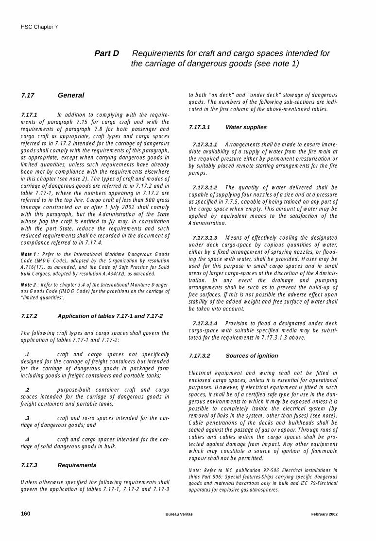
HSC Chapter 7
Part D Requirements for craft and cargo spaces intended forthe carriage of dangerous goods (see note 1)
7.17 General
7.17.1 In addition to complying with the require-ments of paragraph 7.15 for cargo craft and with therequirements of paragraph 7.8 for both passenger andcargo craft as appropriate, craft types and cargo spacesreferred to in 7.17.2 intended for the carriage of dangerousgoods shall comply with the requirements of this paragraph,as appropriate, except when carrying dangerous goods inlimited quantities, unless such requirements have alreadybeen met by compliance with the requirements elsewherein this chapter (see note 2). The types of craft and modes ofcarriage of dangerous goods are referred to in 7.17.2 and intable 7.17-1, where the numbers appearing in 7.17.2 arereferred to in the top line. Cargo craft of less than 500 grosstonnage constructed on or after 1 July 2002 shall complywith this paragraph, but the Administration of the Statewhose flag the craft is entitled to fly may, in consultationwith the port State, reduce the requirements and suchreduced requirements shall be recorded in the document ofcompliance referred to in 7.17.4.
Note 1 : Refer to the International Maritime Dangerous GoodsCode (IMDG Code), adopted by the Organization by resolutionA.716(17), as amended, and the Code of Safe Practice for SolidBulk Cargoes, adopted by resolution A.434(XI), as amended.
Note 2 : Refer to chapter 3.4 of the International Maritime Danger-ous Goods Code (IMDG Code) for the provisions on the carriage of“limited quantities”.
7.17.2 Application of tables 7.17-1 and 7.17-2
The following craft types and cargo spaces shall govern theapplication of tables 7.17-1 and 7.17-2:
.1 craft and cargo spaces not specificallydesigned for the carriage of freight containers but intendedfor the carriage of dangerous goods in packaged formincluding goods in freight containers and portable tanks;
.2 purpose-built container craft and cargospaces intended for the carriage of dangerous goods infreight containers and portable tanks;
.3 craft and ro-ro spaces intended for the car-riage of dangerous goods; and
.4 craft and cargo spaces intended for the car-riage of solid dangerous goods in bulk.
7.17.3 Requirements
Unless otherwise specified the following requirements shallgovern the application of tables 7.17-1, 7.17-2 and 7.17-3
to both “on deck” and “under deck” stowage of dangerousgoods. The numbers of the following sub-sections are indi-cated in the first column of the above-mentioned tables.
7.17.3.1 Water supplies
7.17.3.1.1 Arrangements shall be made to ensure imme-diate availability of a supply of water from the fire main atthe required pressure either by permanent pressurization orby suitably placed remote starting arrangements for the firepumps.
7.17.3.1.2 The quantity of water delivered shall becapable of supplying four nozzles of a size and at a pressureas specified in 7.7.5, capable of being trained on any part ofthe cargo space when empty. This amount of water may beapplied by equivalent means to the satisfaction of theAdministration.
7.17.3.1.3 Means of effectively cooling the designatedunder deck cargo-space by copious quantities of water,either by a fixed arrangement of spraying nozzles, or flood-ing the space with water, shall be provided. Hoses may beused for this purpose in small cargo spaces and in smallareas of larger cargo-spaces at the discretion of the Adminis-tration. In any event the drainage and pumpingarrangements shall be such as to prevent the build-up offree surfaces. If this is not possible the adverse effect uponstability of the added weight and free surface of water shallbe taken into account.
7.17.3.1.4 Provision to flood a designated under deckcargo-space with suitable specified media may be substi-tuted for the requirements in 7.17.3.1.3 above.
7.17.3.2 Sources of ignition
Electrical equipment and wiring shall not be fitted inenclosed cargo spaces, unless it is essential for operationalpurposes. However, if electrical equipment is fitted in suchspaces, it shall be of a certified safe type for use in the dan-gerous environments to which it may be exposed unless it ispossible to completely isolate the electrical system (byremoval of links in the system, other than fuses) (see note).Cable penetrations of the decks and bulkheads shall besealed against the passage of gas or vapour. Through runs ofcables and cables within the cargo spaces shall be pro-tected against damage from impact. Any other equipmentwhich may constitute a source of ignition of flammablevapour shall not be permitted.
Note: Refer to IEC publication 92-506 Electrical installations inships Part 506: Special features-Ships carrying specific dangerousgoods and materials hazardous only in bulk and IEC 79-Electricalapparatus for explosive gas atmospheres.
160 Bureau Veritas February 2002
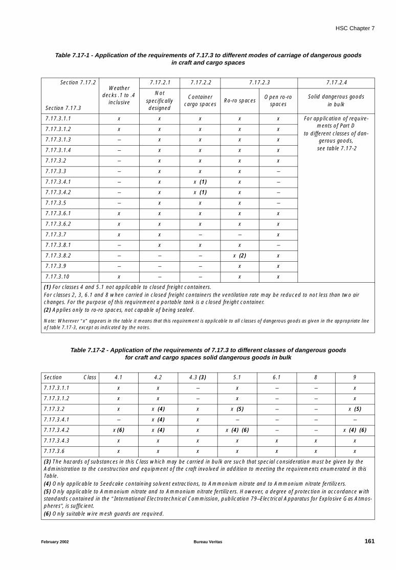
HSC Chapter 7
Table 7.17-1 - Application of the requirements of 7.17.3 to different modes of carriage of dangerous goodsin craft and cargo spaces
Table 7.17-2 - Application of the requirements of 7.17.3 to different classes of dangerous goodsfor craft and cargo spaces solid dangerous goods in bulk
Section 7.17.2Weather
decks .1 to .4 inclusive
7.17.2.1 7.17.2.2 7.17.2.3 7.17.2.4
Section 7.17.3
Notspecifically designed
Container cargo spaces
Ro-ro spacesOpen ro-ro
spacesSolid dangerous goods
in bulk
7.17.3.1.1 x x x x x For application of require-ments of Part D
to different classes of dan-gerous goods,
see table 7.17-2
7.17.3.1.2 x x x x x
7.17.3.1.3 – x x x x
7.17.3.1.4 – x x x x
7.17.3.2 – x x x x
7.17.3.3 – x x x –
7.17.3.4.1 – x x (1) x –
7.17.3.4.2 – x x (1) x –
7.17.3.5 – x x x –
7.17.3.6.1 x x x x x
7.17.3.6.2 x x x x x
7.17.3.7 x x – – x
7.17.3.8.1 – x x x –
7.17.3.8.2 – – – x (2) x
7.17.3.9 – – – x x
7.17.3.10 x – – x x
(1) For classes 4 and 5.1 not applicable to closed freight containers.For classes 2, 3, 6.1 and 8 when carried in closed freight containers the ventilation rate may be reduced to not less than two air changes. For the purpose of this requirement a portable tank is a closed freight container.(2) Applies only to ro-ro spaces, not capable of being sealed.
Note: Wherever “x” appears in the table it means that this requirement is applicable to all classes of dangerous goods as given in the appropriate line of table 7.17-3, except as indicated by the notes.
Section Class 4.1 4.2 4.3 (3) 5.1 6.1 8 9
7.17.3.1.1 x x – x – – x
7.17.3.1.2 x x – x – – x
7.17.3.2 x x (4) x x (5) – – x (5)
7.17.3.4.1 – x (4) x – – – –
7.17.3.4.2 x (6) x (4) x x (4) (6) – – x (4) (6)
7.17.3.4.3 x x x x x x x
7.17.3.6 x x x x x x x
(3) The hazards of substances in this Class which may be carried in bulk are such that special consideration must be given by the Administration to the construction and equipment of the craft involved in addition to meeting the requirements enumerated in this Table.(4) Only applicable to Seedcake containing solvent extractions, to Ammonium nitrate and to Ammonium nitrate fertilizers.(5) Only applicable to Ammonium nitrate and to Ammonium nitrate fertilizers. However, a degree of protection in accordance with standards contained in the “International Electrotechnical Commission, publication 79–Electrical Apparatus for Explosive Gas Atmos-pheres”, is sufficient.(6) Only suitable wire mesh guards are required.
February 2002 Bureau Veritas 161
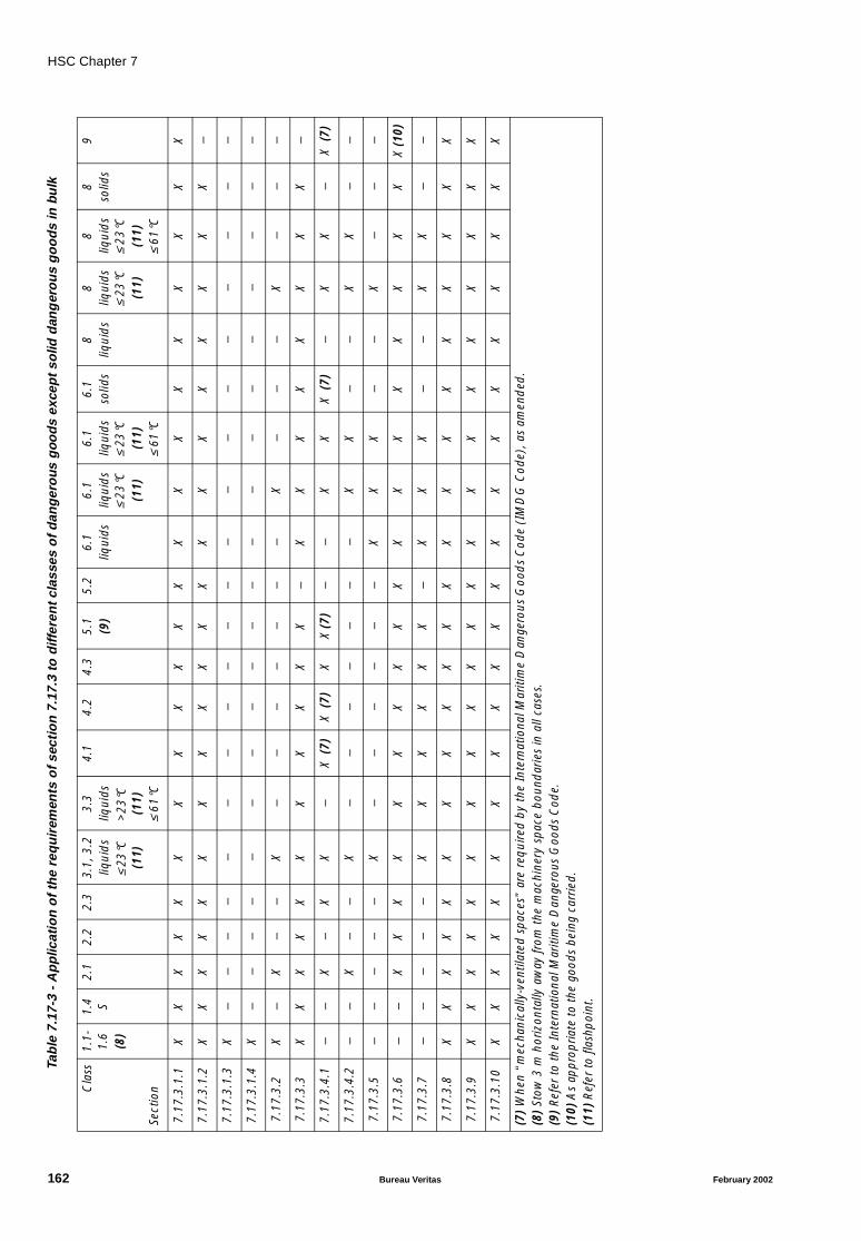
HSC Chapter 7
Table
7.17
-3-
Ap
plic
atio
no
fth
ere
qu
irem
ents
of
sect
ion
7.17
.3to
diff
eren
tcla
sses
of
dan
ger
ous
goo
ds
exce
pt
solid
dan
ger
ou
sg
oo
ds
inbu
lk
Cla
ss1.
1-1.
6(8
)
1.4 S
2.1
2.2
2.3
3.1,
3.2
liqui
ds
≤ 23
°C
(11)
3.3
liqui
ds>
23°C
(1
1)≤
61°C
4.1
4.2
4.3
5.1
(9)
5.2
6.1
liqui
ds6.
1liq
uid
s ≤
23°C
(11)
6.1
liqui
ds
≤ 23
°C(1
1)≤
61°C
6.1
solid
s8
liqui
ds
8liq
uids
≤
23°C
(11)
8liq
uid
s ≤
23°C
(11)
≤ 61
°C
8so
lids
9
Sect
ion
7.1
7.3.
1.1
XX
XX
XX
XX
XX
XX
XX
XX
XX
XX
X
7.1
7.3.
1.2
XX
XX
XX
XX
XX
XX
XX
XX
XX
XX
–
7.1
7.3.
1.3
X–
––
––
––
––
––
––
––
––
––
–
7.1
7.3.
1.4
X–
––
––
––
––
––
––
––
––
––
–
7.1
7.3.
2 X
–X
––
X–
––
––
––
X–
––
X–
––
7.1
7.3.
3 X
XX
XX
XX
XX
XX
–X
XX
XX
XX
X–
7.1
7.3.
4.1
––
X–
XX
–X
(7)
X (
7)X
X (7
)–
–X
XX
(7)
–X
X–
X (
7)
7.1
7.3.
4.2
––
X–
–X
––
––
––
–X
X–
–X
X–
–
7.1
7.3.
5 –
––
––
X–
––
––
–X
XX
––
X–
––
7.1
7.3.
6 –
–X
XX
XX
XX
XX
XX
XX
XX
XX
XX
(10)
7.1
7.3.
7 –
––
––
XX
XX
XX
–X
XX
––
XX
––
7.1
7.3.
8 X
XX
XX
XX
XX
XX
XX
XX
XX
XX
XX
7.1
7.3.
9 X
XX
XX
XX
XX
XX
XX
XX
XX
XX
XX
7.1
7.3.
10
XX
XX
XX
XX
XX
XX
XX
XX
XX
XX
X
(7)
Whe
n “m
echa
nica
lly-v
entil
ated
spa
ces”
are
req
uire
d by
the
Inte
rnat
iona
l Mar
itim
e D
ange
rous
Goo
ds
Cod
e (I
MD
G C
ode)
, as
amen
ded
.(8
) St
ow 3
m h
oriz
onta
lly a
way
from
the
mac
hine
ry s
pace
bou
ndar
ies
in a
ll ca
ses.
(9)
Ref
er to
the
Inte
rnat
iona
l Mar
itim
e D
ange
rous
Goo
ds C
ode.
(10)
As
appr
opria
te t
o th
e go
ods
bein
g ca
rrie
d.(1
1) R
efer
to fl
ashp
oint
.
162 Bureau Veritas February 2002
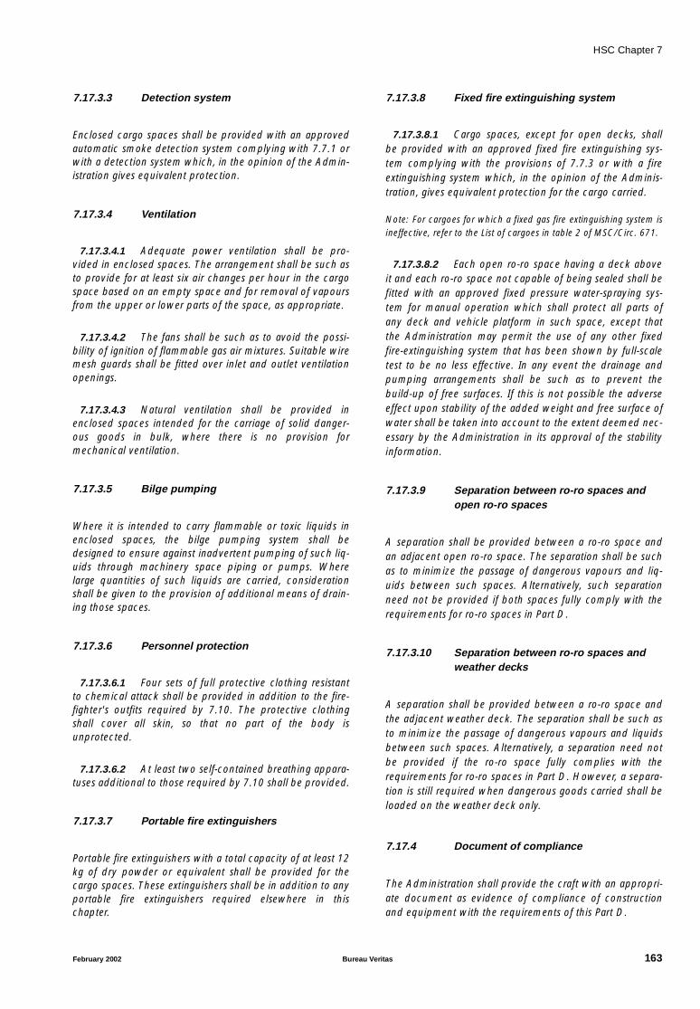
HSC Chapter 7
7.17.3.3 Detection system
Enclosed cargo spaces shall be provided with an approvedautomatic smoke detection system complying with 7.7.1 orwith a detection system which, in the opinion of the Admin-istration gives equivalent protection.
7.17.3.4 Ventilation
7.17.3.4.1 Adequate power ventilation shall be pro-vided in enclosed spaces. The arrangement shall be such asto provide for at least six air changes per hour in the cargospace based on an empty space and for removal of vapoursfrom the upper or lower parts of the space, as appropriate.
7.17.3.4.2 The fans shall be such as to avoid the possi-bility of ignition of flammable gas air mixtures. Suitable wiremesh guards shall be fitted over inlet and outlet ventilationopenings.
7.17.3.4.3 Natural ventilation shall be provided inenclosed spaces intended for the carriage of solid danger-ous goods in bulk, where there is no provision formechanical ventilation.
7.17.3.5 Bilge pumping
Where it is intended to carry flammable or toxic liquids inenclosed spaces, the bilge pumping system shall bedesigned to ensure against inadvertent pumping of such liq-uids through machinery space piping or pumps. Wherelarge quantities of such liquids are carried, considerationshall be given to the provision of additional means of drain-ing those spaces.
7.17.3.6 Personnel protection
7.17.3.6.1 Four sets of full protective clothing resistantto chemical attack shall be provided in addition to the fire-fighter's outfits required by 7.10. The protective clothingshall cover all skin, so that no part of the body isunprotected.
7.17.3.6.2 At least two self-contained breathing appara-tuses additional to those required by 7.10 shall be provided.
7.17.3.7 Portable fire extinguishers
Portable fire extinguishers with a total capacity of at least 12kg of dry powder or equivalent shall be provided for thecargo spaces. These extinguishers shall be in addition to anyportable fire extinguishers required elsewhere in thischapter.
7.17.3.8 Fixed fire extinguishing system
7.17.3.8.1 Cargo spaces, except for open decks, shallbe provided with an approved fixed fire extinguishing sys-tem complying with the provisions of 7.7.3 or with a fireextinguishing system which, in the opinion of the Adminis-tration, gives equivalent protection for the cargo carried.
Note: For cargoes for which a fixed gas fire extinguishing system isineffective, refer to the List of cargoes in table 2 of MSC/Circ. 671.
7.17.3.8.2 Each open ro-ro space having a deck aboveit and each ro-ro space not capable of being sealed shall befitted with an approved fixed pressure water-spraying sys-tem for manual operation which shall protect all parts ofany deck and vehicle platform in such space, except thatthe Administration may permit the use of any other fixedfire-extinguishing system that has been shown by full-scaletest to be no less effective. In any event the drainage andpumping arrangements shall be such as to prevent thebuild-up of free surfaces. If this is not possible the adverseeffect upon stability of the added weight and free surface ofwater shall be taken into account to the extent deemed nec-essary by the Administration in its approval of the stabilityinformation.
7.17.3.9 Separation between ro-ro spaces andopen ro-ro spaces
A separation shall be provided between a ro-ro space andan adjacent open ro-ro space. The separation shall be suchas to minimize the passage of dangerous vapours and liq-uids between such spaces. Alternatively, such separationneed not be provided if both spaces fully comply with therequirements for ro-ro spaces in Part D.
7.17.3.10 Separation between ro-ro spaces andweather decks
A separation shall be provided between a ro-ro space andthe adjacent weather deck. The separation shall be such asto minimize the passage of dangerous vapours and liquidsbetween such spaces. Alternatively, a separation need notbe provided if the ro-ro space fully complies with therequirements for ro-ro spaces in Part D. However, a separa-tion is still required when dangerous goods carried shall beloaded on the weather deck only.
7.17.4 Document of compliance
The Administration shall provide the craft with an appropri-ate document as evidence of compliance of constructionand equipment with the requirements of this Part D.
February 2002 Bureau Veritas 163

HSC Chapter 8
CHAPTER 8 LIFE-SAVING APPLIANCES AND ARRANGEMENTS
8.1 General and definitions
8.1.1 Life-saving appliances and arrangementsshall enable abandonment of the craft in accordance withthe requirements of 4.7 and 4.8.
8.1.2 Except where otherwise provided in thisCode, the life-saving appliances and arrangements requiredby this chapter shall meet the detailed specifications set outin chapter III of the Convention and the LSA Code and beapproved by the Administration.
C8.1.2 Davits and life saving arrangements perma-nently attached to the hull structure are to be examined bythe Society in accordance with the applicable requirementsof Chapter III of the Convention and the LSA Code.
8.1.3 Before giving approval to life-saving appli-ances and arrangements, the Administration shall ensurethat such life-saving appliances and arrangements:
.1 are tested to confirm that they comply withthe requirements of this chapter, in accordance with therecommendations of the Organization (see note); or
.2 have successfully undergone, to the satisfac-tion of the Administration, tests which are substantiallyequivalent to those specified in those recommendations.
Note: Refer to the Revised Recommendation on Testing of Life-Sav-ing Appliances, adopted by the Organization by resolutionMSC.81(70).
8.1.4 Before giving approval to novel life-savingappliances or arrangements, the Administration shall ensurethat such appliances or arrangements:
.1 provide safety standards at least equivalentto the requirements of this chapter and have been evaluatedand tested in accordance with the recommendations of theOrganization (see note); or
.2 have successfully undergone, to the satisfac-tion of the Administration, evaluation and tests which aresubstantially equivalent to those recommendations.
Note: Refer to the Code of Practice for the Evaluation, Testing andAcceptance of Prototype Novel Life-Saving Appliances andArrangements, adopted by the Organization by resolutionA.520(13).
8.1.5 Before accepting life-saving appliances andarrangements that have not been previously approved bythe Administration, the Administration shall be satisfied thatlife-saving appliances and arrangements comply with therequirements of this chapter.
8.1.6 Except where otherwise provided in thisCode, life-saving appliances required by this chapter forwhich detailed specifications are not included in the LSACode shall be to the satisfaction of the Administration.
8.1.7 The Administration shall require life-savingappliances to be subjected to such production tests as arenecessary to ensure that the life-saving appliances are man-ufactured to the same standard as the approved prototype.
8.1.8 Procedures adopted by the Administrationfor approval shall also include the conditions wherebyapproval would continue or would be withdrawn.
8.1.9 The Administration shall determine theperiod of acceptability of life-saving appliances which aresubject to deterioration with age. Such life-saving appli-ances shall be marked with a means for determining theirage or the date by which they shall be replaced.
8.1.10 For the purposes of this chapter, unlessexpressly provided otherwise:
.1 “Detection” is the determination of the loca-tion of survivors or survival craft.
.2 “Embarkation ladder” is the ladder providedat survival craft embarkation stations to permit safe accessto survival craft after launching.
.3 “Embarkation station” is the place fromwhich a survival craft is boarded. An embarkation stationmay also serve as an assembly station, provided there is suf-ficient room, and the assembly station activities can safelytake place there.
.4 “Float-free launching” is that method oflaunching a survival craft whereby the craft is automaticallyreleased from a sinking craft and is ready for use.
.5 “Free-fall launching” is that method oflaunching a survival craft whereby the craft with its comple-ment of persons and equipment on board is released andallowed to fall into the sea without any restrainingapparatus.
164 Bureau Veritas February 2002

HSC Chapter 8
.6 “Immersion suit” is a protective suit whichreduces the body heat-loss of a person wearing it in coldwater.
.7 “Inflatable appliance” is an appliance whichdepends upon non-rigid, gas-filled chambers for buoyancyand which is normally kept uninflated until ready for use.
.8 “Inflated appliance” is an appliance whichdepends upon non-rigid, gas-filled chambers for buoyancyand which is normally kept inflated and ready for use at alltimes.
.9 “Launching appliance or arrangement” is ameans of transferring a survival craft or rescue boat from itsstowed position safely to the water.
.10 “Marine evacuation system (MES)” is anappliance designed to rapidly transfer a large number ofpersons from an embarkation station by means of a passageto a floating platform for subsequent embarkation into asso-ciated survival craft or directly into associated survival craft.
.11 “Novel life-saving appliance or arrangement”is a life-saving appliance or arrangement which embodiesnew features not fully covered by the provisions of thischapter but which provides an equal or higher standard ofsafety.
.12 “Rescue boat” is a boat designed to assistand rescue persons in distress and to marshal survival craft.
.13 “Retrieval” is the safe recovery of survivors.
.14 “Retro-reflective material” is a materialwhich reflects in the opposite direction a beam of lightdirected on it.
.15 “Survival craft” is a craft capable of sustain-ing the lives of persons in distress from the time ofabandoning the craft.
.16 “Thermal protective aid” is a bag or suit ofwaterproof material with low thermal conductance.
8.2 Communications
8.2.1 Craft shall be provided with the followingradio life-saving appliances:
.1 at least three two-way VHF radiotelephoneapparatus shall be provided on every passenger high-speedcraft and on every cargo high-speed craft of 500 gross ton-nage and upwards. Such apparatus shall conform toperformance standards not inferior to those adopted by theOrganization (see note 1);
.2 at least one radar transponder shall be car-ried on each side of every passenger high-speed craft and ofevery cargo high-speed craft of 500 gross tonnage andupwards. Such radar transponders shall conform to per-formance standards not inferior to those adopted by theOrganization (see note 2). The radar transponders shall bestowed in such locations that they can be rapidly placed inany one of the liferafts. Alternatively, one radar transpondershall be stowed in each survival craft.
Note 1 : Refer to the Recommendation on Performance Standardsfor Survival Craft Portable Two-Way VHF Radiotelephone Appara-tus, adopted by the Organization by resolution A.809(19).
Note 2 : Refer to the Recommendation on Performance Standardsfor Survival Craft Radar Transponders for Use in Search and RescueOperations, adopted by the Organization by resolution A.802(19).
8.2.2 Craft shall be provided with the following on-board communications and alarm systems:
.1 an emergency means comprising either fixedor portable equipment or both for two-way communica-tions between emergency control stations, assembly andembarkation stations and strategic positions on board;
.2 a general emergency alarm system comply-ing with the requirements of paragraph 7.2.1 of the LSACode to be used for summoning passengers and crew toassembly stations and to initiate the actions included in themuster list. The system shall be supplemented by a publicaddress system complying with the requirements of para-graph 7.2.2 of the LSA Code, or by other suitable means ofcommunication. The systems shall be operable from theoperating compartment.
8.2.3 Signalling equipment
8.2.3.1 All craft shall be provided with a portabledaylight signalling lamp which is available for use in theoperating compartment at all times and which is notdependent on the craft's main source of electrical power.
8.2.3.2 Craft shall be provided with not less than 12rocket parachute flares, complying with the requirements ofparagraph 3.1 of the LSA Code, stowed in or near the oper-ating compartment.
8.3 Personal life-saving appliances
8.3.1 Where passengers or crew have access toexposed decks under normal operating conditions, at leastone lifebuoy on each side of the craft capable of quickrelease from the control compartment and from a positionat or near where it is stowed, shall be provided with a self-igniting light and a self-activating smoke signal. The posi-tioning and securing arrangements of the self-activatingsmoke signal shall be such that it cannot be released or acti-
February 2002 Bureau Veritas 165
HSC Chapter 8
vated solely by the accelerations produced by collisions orgroundings.
8.3.2 At least one lifebuoy shall be provided adja-cent to each normal exit from the craft and on each opendeck to which passengers and crew have access, subject toa minimum of two being installed.
8.3.3 Lifebuoys fitted adjacent to each normal exitfrom the craft shall be fitted with buoyant lines of at least 30m in length.
8.3.4 Not less than half the total number of lifebu-oys shall be fitted with self-igniting lights. However, thelifebuoys provided with self-igniting lights shall not includethose provided with lines in accordance with 8.3.3.
8.3.5 A lifejacket complying with the requirementsof paragraph 2.2.1 or 2.2.2 of the LSA Code be provided forevery person on board the craft and, in addition:
.1 a number of lifejackets suitable for childrenequal to at least 10% of the number of passengers on boardshall be provided or such greater number as may berequired to provide a lifejacket for each child;
.2 every passenger craft shall carry lifejacketsfor not less than 5% of the total number of persons onboard. These lifejackets shall be stowed in conspicuousplaces on deck or at assembly stations;
.3 a sufficient number of lifejackets shall be car-ried for persons on watch and for use at remotely locatedsurvival craft and rescue boat stations; and
.4 all lifejackets shall be fitted with a light,which complies with the requirements of paragraph 2.2.3 ofthe LSA Code.
8.3.6 Lifejackets shall be so placed as to be readilyaccessible and their positions shall be clearly indicated.
8.3.7 An immersion suit, of an appropriate size,complying with the requirements of paragraph 2.3 of theLSA Code shall be provided for every person assigned tocrew the rescue boat.
8.3.8 An immersion suit or anti-exposure suit shallbe provided for each member of the crew assigned, in themuster list, to duties in an MES party for embarking passen-gers into survival craft. These immersion suits or anti-exposure suits need not be required if the craft is constantlyengaged on voyages in warm climates where, in the opinionof the Administration, such suits are unnecessary.
8.4 Muster list, emergencyinstructions and manuals
8.4.1 Clear instructions to be followed in the eventof an emergency shall be provided for each person onboard.
Note: Refer to the Guidelines for passenger safety instructions onro-ro passenger ships (MSC/Circ.681).
8.4.2 Muster lists complying with the requirementsof regulation III/37 of the Convention shall be exhibited inconspicuous places throughout the craft including the con-trol compartment, engine-room and crew accommodationspaces.
8.4.3 Illustrations and instructions in appropriatelanguages shall be posted in public spaces and be conspicu-ously displayed at assembly stations, at other passengerspaces and near each seat to inform passengers of:
.1 their assembly station;
.2 the essential actions they must take in anemergency;
.3 the method of donning lifejackets.
8.4.4 Every passenger craft shall have passengerassembly stations:
.1 in the vicinity of, and which provide readyaccess for all the passengers to, the embarkation stationsunless in the same location; and
.2 which have ample room for the marshallingand instruction of passengers.
8.4.5 A training manual complying with therequirements of 18.2.3 shall be provided in each crewmessroom and recreation room.
8.5 Operating instructions
8.5.1 Poster or signs shall be provided on or in thevicinity of survival craft and their launching controls andshall:
.1 illustrate the purpose of controls and the pro-cedures for operating the appliance and give relevantinstructions and warnings:
.2 be easily seen under emergency lightingconditions;
166 Bureau Veritas February 2002
HSC Chapter 8
.3 use symbols in accordance with the recom-mendations of the Organization (see note).
Note: Refer to Symbols related to Life-Saving Appliances andArrangements, adopted by the Organization by resolutionA.760(18), as amended by resolution MSC.82(70).
8.6 Survival craft stowage
8.6.1 Survival craft shall be securely stowed out-side and as close as possible to the passenger accommoda-tion and embarkation stations. The stowage shall be suchthat each survival craft can be safely launched in a simplemanner and remain secured to the craft during and subse-quent to the launching procedure. The length of the secur-ing lines and the arrangements of the bowsing lines shall besuch as to maintain the survival craft suitably positioned forembarkation. The Administrations may permit the use of ad-justable securing and/or bowsing lines at exits where morethan one survival craft is used. The securing arrangementsfor all securing and bowsing lines shall be of sufficientstrength to hold the survival craft in position during theevacuation process.
8.6.2 Survival craft shall be so stowed as to permitrelease from their securing arrangements at or near to theirstowage position on the craft and from a position at or nearto the operating compartment.
8.6.3 So far as is practicable, survival craft shall bedistributed in such a manner that there is an equal capacityon both sides of the craft.
8.6.4 The launching procedure for inflatable lifer-afts shall, where practicable, initiate inflation. Where it isnot practicable to provide automatic inflation of liferafts (forexample, when the liferafts are associated with an MES), thearrangement shall be such that the craft can be evacuatedwithin the time specified in 4.8.1.
8.6.5 Survival craft shall be capable of beinglaunched and then boarded from the designated embarka-tion stations in all operational conditions and also in allconditions of flooding after receiving damage to the extentprescribed in chapter 2.
8.6.6 Survival craft launching stations shall be insuch positions as to ensure safe launching having particularregard to clearance from the propeller or waterjet andsteeply overhanging portions of the hull.
8.6.7 During preparation and launching, the sur-vival craft and the area of water into which it is to belaunched shall be adequately illuminated by the lightingsupplied from the main and emergency sources of electricalpower required by chapter 12.
8.6.8 Means shall be available to prevent any dis-charge of water on to survival craft when launched.
8.6.9 Each survival craft shall be stowed:
.1 so that neither the survival craft nor its stow-age arrangements will interfere with the operation of anyother survival craft or rescue boat at any other launchingstation;
.2 in a state of continuous readiness;
.3 fully equipped; and
.4 as far as practicable, in a secure and shel-tered position and protected from damage by fire andexplosion.
8.6.10 Every liferaft shall be stowed with its painterpermanently attached to the craft and with a float freearrangement complying with the requirements of paragraph4.1.6 of the LSA Code so that, as far as practicable, the lifer-aft floats free and, if inflatable, inflates automatically shouldthe high speed craft sink.
8.6.11 Rescue boats shall be stowed:
.1 in a state of continuous readiness for launch-ing in not more than 5 min;
.2 in a position suitable for launching andrecovery; and
.3 so that neither the rescue boat nor its stow-age arrangements will interfere with the operation ofsurvival craft at any other launching station.
8.6.12 Rescue boats and survival craft shall besecured and fastened to the deck so that they at least with-stand the loads likely to arise due to a defined horizontalcollision load for the actual craft and the vertical designload at the stowage position.
8.7 Survival craft and rescue boatembarkation and recoveryarrangements
8.7.1 Embarkation stations shall be readily accessi-ble from accommodation and work areas. If the designatedassembly stations are other than the passenger spaces, theassembly stations shall be readily accessible from the pas-senger spaces, and the embarkation stations shall be readilyaccessible from the assembly stations.
8.7.2 Evacuation routes, exits and embarkationpoints shall comply with the requirements of 4.7.
February 2002 Bureau Veritas 167
HSC Chapter 8
8.7.3 Alleyways, stairways and exits giving accessto the assembly and embarkation stations shall be ade-quately illuminated by lighting supplied from the main andemergency source of electrical power required by chapter12.
8.7.4 Where davit-launched survival craft are notfitted, MES or equivalent means of evacuation shall be pro-vided in order to avoid persons entering the water to boardsurvival craft. Such MES or equivalent means of evacuationshall be so designed as to enable persons to board survivalcraft in all operational conditions and also in all conditionsof flooding after receiving damage to the extent prescribedin chapter 2.
8.7.5 Subject to survival craft and rescue boatembarkation arrangements being effective within the envi-ronmental conditions in which the craft is permitted tooperate and in all undamaged and prescribed damage con-ditions of trim and heel, where the freeboard between theintended embarkation position and the waterline is notmore than 1.5 m, the Administration may accept a systemwhere persons board liferafts directly.
8.7.6 Rescue boat embarkation arrangements shallbe such that the rescue boat can be boarded and launcheddirectly from the stowed position and recovered rapidlywhen loaded with its full complement of persons andequipment.
8.7.7 Launching systems for rescue boats on cate-gory B craft may be based on power supply from the craft'spower supply under the following conditions:
.1 the davit or crane shall be supplied withpower from 2 sources in each independent engine room;
.2 the davit or crane shall comply with therequired launching, lowering and hoisting speeds whenusing only one power source; and
.3 the davit or crane is not required to be acti-vated from a position within the rescue boat.
8.7.8 On multihull craft with a small HL1angle ofheel and trim, the design angles in paragraph 6.1 of the LSACode may be changed from 20° / 10° to the maximumangles calculated in accordance with annex 7, includingheeling lever HL2, HTL, HL3 or HL4.
8.7.9 Rescue boat davits or cranes may bedesigned for launching and recovering the boat with 3 per-sons only on the condition that an additional boardingarrangement is available on each side complying with 8.7.5.
8.7.10 A safety knife shall be provided at each MESembarkation station.
8.8 Line-throwing appliance
A line-throwing appliance complying with the requirementsof paragraph 7.1 of the LSA Code shall be provided.
8.9 Operational readiness,maintenance and inspections
8.9.1 Operational readiness
Before the craft leaves port and at all times during the voy-age, all life-saving appliances shall be in working order andready for immediate use.
8.9.2 Maintenance
.1 Instructions for on-board maintenance of life-saving appliances complying with the requirements of regu-lation III/36 of the Convention shall be provided andmaintenance shall be carried out accordingly.
.2 The Administration may accept, in lieu of theinstructions required by .1, a shipboard planned mainte-nance programme which includes the requirements ofregulation III/36 of the Convention.
8.9.3 Maintenance of falls
8.9.3.1 Falls used in launching shall be turned endfor end at intervals of not more than 30 months and berenewed when necessary due to deterioration of the falls orat intervals of not more than five years, whichever is theearlier.
8.9.3.2 The Administration may accept in lieu of“end for ending” required in 8.9.3.1, periodic inspection ofthe falls and their renewal whenever necessary due to dete-rioration or at intervals of not more than four years,whichever is the earlier.
8.9.4 Spares and repair equipment
Spares and repair equipment shall be provided for life-sav-ing appliances and their components which are subject toexcessive wear or consumption and need to be replacedregularly.
8.9.5 Weekly inspection
The following tests and inspections shall be carried outweekly:
.1 all survival craft, rescue boats and launchingappliances shall be visually inspected to ensure that theyare ready for use;
168 Bureau Veritas February 2002
HSC Chapter 8
.2 all engines in rescue boats shall be run aheadand astern for a total period of not less than 3 min providedthe ambient temperature is above the minimum tempera-ture required for starting and running the engine. Duringthis period of time, it should be demonstrated that the gear-box and gearbox train are engaging satisfactorily. If thespecial characteristics of an outboard motor fitted to a res-cue boat would not allow it to be run other than with itspropeller submerged for a period of 3 min, it should be runfor such period as prescribed in the manufacturer's hand-book; and
.3 the general emergency alarm system shall betested.
8.9.6 Monthly inspections
Inspection of the life-saving appliances, including survivalcraft equipment shall be carried out monthly using thechecklist required by regulation III/36.1 of the Conventionto ensure that they are complete and in good order. Areport of the inspection shall be entered in the log-book.
8.9.7 Servicing of inflatable liferafts, inflatablelifejackets, marine evacuation systemsand inflated rescue boats
8.9.7.1 Every inflatable liferaft, inflatable lifejacketand MES shall be serviced:
.1 at intervals not exceeding 12 months, pro-vided where in any case this is impracticable, theAdministration may extend this period by one month;
.2 at an approved servicing station which iscompetent to service them, maintains proper servicing facil-ities and uses only properly trained personnel.
Note: Refer to the Recommendation on Conditions for theApproval of Servicing Stations for Inflatable Liferafts, adopted bythe Organization by resolution A.761(18), as amended by resolu-tion MSC.55(66).
8.9.8 Rotational deployment of marineevacuation systems
In addition to or in conjunction with the servicing intervalsof marine evacuation systems required by 8.9.7.1, eachmarine evacuation system shall be deployed from the crafton a rotational basis at intervals to be agreed by the Admin-istration provided that each system is to be deployed at leastonce every six years.
8.9.9 An Administration which approves new andnovel inflatable liferaft arrangements pursuant to 8.1 mayallow for extended service intervals under the followingconditions:
8.9.9.1 The new and novel liferaft arrangement shallmaintain the same standard, as required by testing proce-dure, throughout the extended service intervals.
8.9.9.2 The liferaft system shall be checked on boardby certified personnel according to paragraph 8.9.7.1.
8.9.9.3 Service at intervals not exceeding five yearsshall be carried out in accordance with recommendationsof the Organization.
8.9.10 All repairs and maintenance of inflated res-cue boats shall be carried out in accordance with themanufacturer's instructions. Emergency repairs may be car-ried out on board the craft, however, permanent repairsshall be effected at an approved servicing station.
8.9.11 An Administration which permits extensionof liferaft service intervals in accordance with 8.9.9 shallnotify the Organization of such action in accordance withregulation I/5(b) of the Convention.
8.9.12 Periodic servicing of hydrostatic releaseunits
Hydrostatic release units shall be serviced:
.1 at intervals not exceeding 12 months, pro-vided where in any case this is impracticable, theAdministration may extend this period by one month;
.2 at a servicing station which is competent toservice them, maintains proper servicing facilities and usesonly properly trained personnel.
8.9.13 Marking of stowage locations
Containers, brackets, racks and other similar stowage loca-tions for life-saving equipment, shall be marked withsymbols in accordance with the recommendations of theOrganization, indicating the devices stowed in that locationfor that purpose. If more than one device is stowed in thatlocation, the number of devices shall also be indicated.
8.9.14 Periodic servicing of launchingappliances
8.9.14.1 Launching appliances:
.1 shall be serviced at recommended intervalsin accordance with instructions for on-board maintenanceas required by regulation III/36 of the Convention;
.2 shall be subjected to a thorough examinationat intervals not exceeding 5 years; and
February 2002 Bureau Veritas 169
HSC Chapter 8
.3 shall upon completion of the examination in.2 be subjected to a dynamic test of the winch brake inaccordance with paragraph 6.1.2.5.2 of the LSA Code.
8.10 Survival craft and rescue boats
8.10.1 All craft shall carry:
.1 survival craft with sufficient capacity as willaccommodate not less than 100% of the total number ofpersons the craft is certified to carry, subject to a minimumof two such survival craft being carried;
.2 in addition, survival craft with sufficientaggregate capacity to accommodate not less than 10% ofthe total number of persons the craft is certified to carry;
.3 sufficient survival craft to accommodate thetotal number of persons the craft is certified to carry, even inthe event that all the survival craft to one side of the craftcentreline and within the longitudinal extent of damagedefined in 2.6.7.1 are considered lost or renderedunserviceable;
.4 at least one rescue boat for retrieving personsfrom the water, but not less than one such boat on eachside when the craft is certified to carry more than 450passengers;
.5 craft of less than 30 m in length may beexempted from carrying a rescue boat, provided the craftmeets all of the following requirements:
.5.1 the craft is arranged to allow a helpless personto be recovered from the water;
.5.2 recovery of the helpless person can be observedfrom the navigating bridge; and
.5.3 the craft is sufficiently manoeuvrable to close inand recover persons in the worst intendedconditions.
.6 notwithstanding the provisions of .4 and .5above, craft shall carry sufficient rescue boats to ensurethat, in providing for abandonment by the total number ofpersons the craft is certified to carry:
.6.1 not more than nine of the liferafts provided inaccordance with 8.10.1.1 are marshalled byeach rescue boat; or
.6.2 if the Administration is satisfied that the rescueboats are capable of towing a pair of such lifer-afts simultaneously, not more than 12 of theliferafts provided in accordance with 8.10.1.1are marshalled by each rescue boat; and
.6.3 the craft can be evacuated within the time spec-ified in 4.8.
8.10.2 Where the Administration considers it appro-priate, in view of the sheltered nature of the voyages andthe suitable climatic conditions of the intended area ofoperations, the Administration may permit the use of openreversible inflatable liferafts complying with annex 11 oncategory A craft as an alternative to liferafts complying withparagraph 4.2 or 4.3 of the LSA Code.
8.11 Helicopter pick-up areas
8.11.1 Craft operating on voyages having a durationof 2 h or more between each port of call shall be providedwith a helicopter pick-up area approved by the Administra-tion having regard to the recommendations adopted by theOrganization.
Note: Refer to the Merchant ship search and rescue manual (MER-SAR), adopted by the Organization by resolution A.229(VII), asamended.
170 Bureau Veritas February 2002
HSC Chapter 9
CHAPTER 9 MACHINERY
Part A General
9.1 General
9.1.1 The machinery, associated piping systemsand fittings relating to main machinery and auxiliary powerunits shall be of a design and construction adequate for theservice for which they are intended and shall be so installedand protected as to reduce to a minimum any danger topersons on board, due regard being paid to moving parts,hot surfaces and other hazards. The design shall haveregard to materials used in construction, the purpose forwhich the equipment is intended, the working conditions towhich it will be subjected and the environmental conditionson board.
9.1.2 All surfaces with temperatures exceeding220°C where impingement of flammable liquids may occuras a result of a system failure shall be insulated. The insula-tion shall be impervious to flammable liquids and vapours.
9.1.3 Special consideration shall be given to thereliability of single essential propulsion components and aseparate source of propulsion power sufficient to give thecraft a navigable speed, especially in the case of unconven-tional arrangements, may be required.
9.1.4 Means shall be provided whereby normaloperation of propulsion machinery can be sustained orrestored even though one of the essential auxiliariesbecomes inoperative. Special consideration shall be givento the malfunctioning of:
.1 a generating set which serves as a mainsource of electrical power;
.2 the fuel oil supply systems for engines;
.3 the sources of lubricating oil pressure;
.4 the sources of water pressure;
.5 an air compressor and receiver for starting orcontrol purposes;
.6 the hydraulic, pneumatic or electrical meansfor control in main propulsion machinery, including control-lable-pitch propellers.
However, having regard to overall safety considerations, apartial reduction in propulsion capability from normal oper-ation may be accepted.
9.1.5 Means shall be provided to ensure that themachinery can be brought into operation from the deadcraft condition without external aid.
9.1.6 All parts of machinery, hydraulic, pneumaticand other systems and their associated fittings which areunder internal pressure shall be subjected to appropriatetests including a pressure test before being put into servicefor the first time.
9.1.7 Provision shall be made to facilitate cleaning,inspection and maintenance of main propulsion and auxil-iary machinery including boilers and pressure vessels.
9.1.8 The reliability of machinery installed in thecraft shall be adequate for its intended purpose.
9.1.9 The Administration may accept machinerywhich does not show detailed compliance with the Codewhere it has been used satisfactorily in a similar application,provided that it is satisfied:
.1 that the design, construction, testing, installa-tion and prescribed maintenance are together adequate forits use in a marine environment; and
.2 that an equivalent level of safety will beachieved.
9.1.10 A failure mode and effect analysis shallinclude machinery systems and their associated controls.
9.1.11 Such information as is necessary to ensurethat machinery can be installed correctly regarding suchfactors as operating conditions and limitations shall bemade available by the manufacturers.
February 2002 Bureau Veritas 171
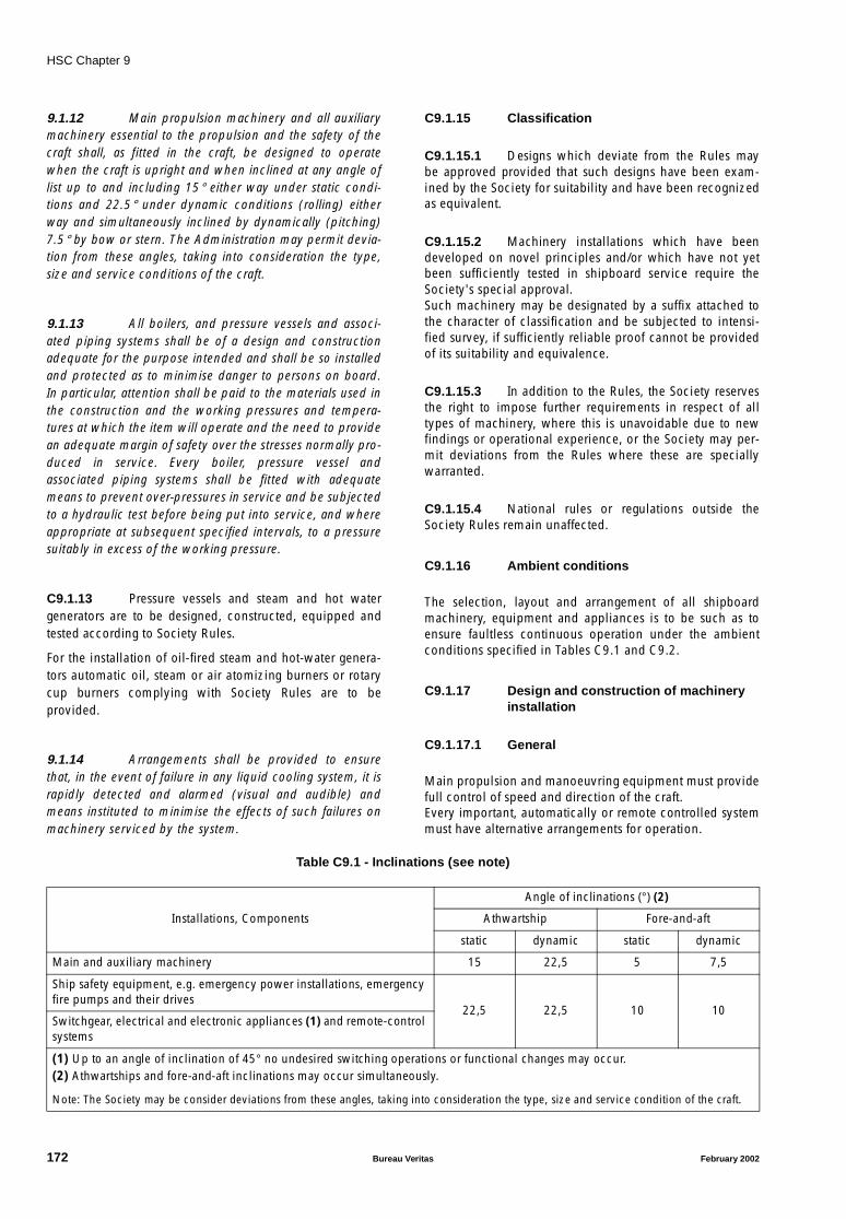
HSC Chapter 9
9.1.12 Main propulsion machinery and all auxiliarymachinery essential to the propulsion and the safety of thecraft shall, as fitted in the craft, be designed to operatewhen the craft is upright and when inclined at any angle oflist up to and including 15° either way under static condi-tions and 22.5° under dynamic conditions (rolling) eitherway and simultaneously inclined by dynamically (pitching)7.5° by bow or stern. The Administration may permit devia-tion from these angles, taking into consideration the type,size and service conditions of the craft.
9.1.13 All boilers, and pressure vessels and associ-ated piping systems shall be of a design and constructionadequate for the purpose intended and shall be so installedand protected as to minimise danger to persons on board.In particular, attention shall be paid to the materials used inthe construction and the working pressures and tempera-tures at which the item will operate and the need to providean adequate margin of safety over the stresses normally pro-duced in service. Every boiler, pressure vessel andassociated piping systems shall be fitted with adequatemeans to prevent over-pressures in service and be subjectedto a hydraulic test before being put into service, and whereappropriate at subsequent specified intervals, to a pressuresuitably in excess of the working pressure.
C9.1.13 Pressure vessels and steam and hot watergenerators are to be designed, constructed, equipped andtested according to Society Rules.
For the installation of oil-fired steam and hot-water genera-tors automatic oil, steam or air atomizing burners or rotarycup burners complying with Society Rules are to beprovided.
9.1.14 Arrangements shall be provided to ensurethat, in the event of failure in any liquid cooling system, it israpidly detected and alarmed (visual and audible) andmeans instituted to minimise the effects of such failures onmachinery serviced by the system.
C9.1.15 Classification
C9.1.15.1 Designs which deviate from the Rules maybe approved provided that such designs have been exam-ined by the Society for suitability and have been recognizedas equivalent.
C9.1.15.2 Machinery installations which have beendeveloped on novel principles and/or which have not yetbeen sufficiently tested in shipboard service require theSociety's special approval.Such machinery may be designated by a suffix attached tothe character of classification and be subjected to intensi-fied survey, if sufficiently reliable proof cannot be providedof its suitability and equivalence.
C9.1.15.3 In addition to the Rules, the Society reservesthe right to impose further requirements in respect of alltypes of machinery, where this is unavoidable due to newfindings or operational experience, or the Society may per-mit deviations from the Rules where these are speciallywarranted.
C9.1.15.4 National rules or regulations outside theSociety Rules remain unaffected.
C9.1.16 Ambient conditions
The selection, layout and arrangement of all shipboardmachinery, equipment and appliances is to be such as toensure faultless continuous operation under the ambientconditions specified in Tables C9.1 and C9.2.
C9.1.17 Design and construction of machineryinstallation
C9.1.17.1 General
Main propulsion and manoeuvring equipment must providefull control of speed and direction of the craft.Every important, automatically or remote controlled systemmust have alternative arrangements for operation.
Table C9.1 - Inclinations (see note)
Installations, Components
Angle of inclinations (°) (2)
Athwartship Fore-and-aft
static dynamic static dynamic
Main and auxiliary machinery 15 22,5 5 7,5
Ship safety equipment, e.g. emergency power installations, emergency fire pumps and their drives
22,5 22,5 10 10Switchgear, electrical and electronic appliances (1) and remote-control systems
(1) Up to an angle of inclination of 45° no undesired switching operations or functional changes may occur.(2) Athwartships and fore-and-aft inclinations may occur simultaneously.
Note: The Society may be consider deviations from these angles, taking into consideration the type, size and service condition of the craft.
172 Bureau Veritas February 2002

HSC Chapter 9
Table C9.2 - Environmental conditions for machinery and electrical installations (see note)
C9.1.17.2 Materials, welding and tests
.1 All materials and components subject to theRules are to be manufactured and tested in accordance withSociety Rules.
.2 The fabrication of welded components,approval of companies and testing of welders are subject toSociety Rules.
.3 Machinery and its components are subject toconstructional and material tests, pressure and leakage testsand trials. All the tests prescribed in the following sectionsare to be conducted under the supervision of the Society.
.4 In the case of parts produced in series, othermethods of testing may be agreed with the Society insteadof the tests prescribed, provided that the former are recog-nized as equivalent by the Society.
.5 The Society reserves the right, where neces-sary, to increase the scope of the tests and also to subject totesting those parts which are not expressly required to betested according to the Rules.
.6 After installation on board of propulsion andauxiliary machinery, operational functioning of the machin-ery including the associated auxiliary equipment is to beverified. All safety equipment is to be tested, unless ade-quate testing has already been performed at themanufacturer's works in the presence of the SocietyRepresentative.
.7 In addition, the entire machinery installationis to be tested during sea trials as far as possible underintended service conditions.
C9.1.18 Shipboard trials (dock and sea trials)
C9.1.18.1 Dock trials are to be carried out to the satis-faction of the Society Surveyor.
C9.1.18.2 Sea trials with propulsion engines drivingfixed propellers:
.1 At rated engine speed no for at least 4 hours,with gas turbines for at least 2 hours;
.2 At minimum on-load speed;
.3 Starting and reversing manoeuvres;
.4 Astern trial with n = 0,7 ⋅ no for at least 15minutes;
.5 Final testing of monitoring and safetysystems.
C9.1.18.3 Sea trials with propulsion engines drivingcontrollable-pitch propellers, reversing gears or water jets:
.1 At 100% power at engine speed no for atleast 4 hours, with gas turbines for at least 2 hours.
.2 Manoeuvring trials with various propellerpitches. Where provision is made for combinator operation,the combinator curves are to be plotted and verified bymeasurements.
.3 Astern trial with approximately 70% powerfor at least 15 minutes.
.4 Final testing of monitoring and safetysystems.
C9.1.18.4 The engines driving electrical generators areto be subjected to an operational test for at least four hoursin accordance with the shipboard test programme of theSociety.
C9.1.18.5 Stopping test from full ahead is to be carriedout. Time and distance are to be noted.
Seawater temperature +32°C
Ambient air temperature −25°C to +45°C, relative humidity (1 bar / 45°C) 60%
Enclosed machinery spaces Temperature range 0°C to 55°C. Relative humidity 100%.Ability to withstand oil vapour and salt-laden air
Air-conditioned control rooms Temperature range 0°C to 40°C. Relative humidity 80%
Open deck Temperature range −25°C to +45°C. Ability to withstand temporary flooding with seawater and salt-laden spray
Note: The Society may approve other conditions for craft operating only in special agreed geographical areas.
February 2002 Bureau Veritas 173
HSC Chapter 9
9.2 Engine (general)
9.2.1 The engines shall be fitted with adequatesafety monitoring and control devices in respect of speed,temperature, pressure and other operational functions. Con-trol of the machinery shall be from the craft's operatingcompartment. Category B craft and cargo craft shall be pro-vided with additional machinery controls in or close to themachinery space. The machinery installation shall be suita-ble for operation as in an unmanned machinery space,including automatic fire detection system, bilge alarm sys-tem, remote machinery instrumentation and alarm system(see note). Where the space is continuously manned, thisrequirement may be varied in accordance with the require-ments of the Administration.
Note: Refer to part E of chapter II-1 of the Convention.
9.2.2 The engines shall be protected against over-speed, loss of lubricating oil pressure, loss of coolingmedium, high temperature, malfunction of moving partsand overload. Safety devices shall not cause completeengine shutdown without prior warning, except in caseswhere there is a risk of complete breakdown or explosion.Such safety devices shall be capable of being tested.
9.2.3 At least two independent means of stoppingthe engines quickly from the operating compartment underany operating conditions shall be available. Duplication ofthe actuator fitted to the engine shall not be required.
9.2.4 The major components of the engine shallhave adequate strength to withstand the thermal anddynamic conditions of normal operation. The engine shallnot be damaged by a limited operation at a speed or at tem-peratures exceeding the normal values but within the rangeof the protective devices.
9.2.5 The design of the engine shall be such as tominimise the risk of fire or explosion and to enable compli-ance with the fire precaution requirements of chapter 7.
9.2.6 Provision shall be made to drain all excessfuel and oil to a safe position so as to avoid a fire hazard.
9.2.7 Provision shall be made to ensure that,whenever practical, the failure of systems driven by theengine shall not unduly affect the integrity of the majorcomponents.
9.2.8 The ventilation arrangements in the machin-ery spaces shall be adequate under all envisaged operatingconditions. Where appropriate, arrangements shall ensurethat enclosed engine compartments are forcibly ventilatedto the atmosphere before the engine can be started.
9.2.9 Any engines shall be so installed as to avoidexcessive vibration within the craft.
9.3 Gas turbines
C9.3.0.1 Documents to be submitted
For every gas turbine installation, the drawings and docu-ments required in Society Rules are to be submitted intriplicate for approval by the turbine manufacturer. TheSociety reserves the right to ask for supplementary copies ifdeemed necessary in particular cases.
C9.3.0.2 The materials of shafts, turbine and compres-sor wheels, guide vanes and blades, turbine andcompressor casings, combustion chambers and heatexchangers are to be tested in accordance with test specifi-cations laid down by the gas turbine manufacturer andrecognized by the Society as part of the approvalprocedure.
9.3.1 Gas turbines shall be designed to operate inthe marine environment and shall be free from surge or dan-gerous instability throughout its operating range up to themaximum steady speed approved for use. The turbineinstallation shall be arranged to ensure that the turbine can-not be continuously operated within any speed range whereexcessive vibration, stalling, or surging may be encountered.
9.3.2 The gas turbines shall be designed andinstalled such that any reasonably probable shedding ofcompressor or turbine blades will not endanger the craft,other machinery, occupants of the craft or any otherpersons.
9.3.3 Requirements of 9.2.6 shall apply to gas tur-bines in respect of fuel which might reach the interior of thejet pipe or exhaust system after a false start or after stopping.
9.3.4 Turbines shall be safeguarded as far as practi-cable against the possibility of damage by ingestion ofcontaminants from the operating environment. Informationregarding the recommended maximum concentration ofcontamination shall be made available. Provision shall bemade for preventing the accumulation of salt deposits onthe compressors and turbines and, if necessary, for prevent-ing the air intake from icing.
9.3.5 In the event of a failure of a shaft or weaklink, the broken end shall not hazard the occupants of thecraft, either directly or by damaging the craft or its systems.Where necessary, guards may be fitted to achieve compli-ance with these requirements.
9.3.6 Each engine shall be provided with an emer-gency overspeed shutdown device connected, wherepossible, directly to each rotor shaft.
C9.3.6 Startup is to take place automatically, in afixed sequence.
174 Bureau Veritas February 2002
HSC Chapter 9
9.3.7 Where an acoustic enclosure is fitted whichcompletely surrounds the gas generator and the high pres-sure oil pipes, a fire detection and extinguishing system shallbe provided for the acoustic enclosure.
9.3.8 Details of the manufacturers' proposed auto-matic safety devices to guard against hazardous conditionsarising in the event of malfunction in the turbine installationshall be provided together with the failure mode and effectanalysis.
9.3.9 The manufacturers shall demonstrate thesoundness of the casings. Intercoolers and heat exchangersshall be hydraulically tested on each side separately.
C9.3.10 The following minimum monitoring equip-ment is to be provided:
.1 Air pressure and temperature at compressorinlet,
.2 Gas pressure and temperature at gas genera-tor outlet,
.3 Lubricating oil pressure and temperature,
.4 Gas generator and power turbine speeds.
C9.3.11 Gas turbine and compressor rotors are to bedynamically balanced when in the condition ready forassembly and are to undergo an overspeed test.
C9.3.12 Sea trials have to be carried out according toC9.1.18.
9.4 Diesel engines for mainpropulsion and essentialauxiliaries
C9.4.0.1 Documents to be submitted
For each diesel engine type, the drawings and documentsrequired in the Society Rules are to be submitted in tripli-cate to the Society for approval by the engine manufacturer.The Society reserves the right to ask for supplementary cop-ies if deemed necessary in particular cases.
C9.4.0.1.1 Auxiliary engines intended as prime moversfor harbour generator sets with less than 50 kW are not sub-ject to approval.
C9.4.0.2 Definitions
C9.4.0.2.1 For the purposes of these Rules, dieselengines are reciprocating internal combustion engines.
C9.4.0.2.2 Diesel engines are to be designed such thattheir rated power when running at rated speed can be deliv-ered as continuous power.
The continuous power for which the engine is to bedesigned is defined as in ISO 3046/1.
C9.4.0.2.3 Subject to the approval of the Society for pro-pulsion plants where overload is used/required frequently,the diesel engines may be designed for a continuous power(fuel stop power) which cannot be exceeded.
C9.4.0.2.4 Diesel engines for installation on board ofhigh speed craft must have been type-tested by the Society.For this purpose, a type-approval test in accordance withSociety Rules for diesel engines is to be performed.
9.4.1 Any main diesel propulsion system shall havesatisfactory torsional vibration and other vibrational charac-teristics verified by individual and combined torsional andother vibration analyses for the system and its componentsfrom power unit through to propulsor.
C9.4.1 The speed ranges where excessive vibrationsmay be encountered are to be marked in red on thetachometer, where practicable, and an instruction plateindicating that the engine is not to be continuously oper-ated within these speed ranges is to be fitted near eachcontrol station.
9.4.2 All external high-pressure fuel delivery linesbetween the high-pressure fuel pumps and fuel nozzlesshall be protected with a jacketed tubing system capable ofcontaining fuel from a high-pressure line failure. The jack-eted tubing system shall include a means for collection ofleakages and arrangements shall be provided for an alarmto be given of a fuel line failure.
9.4.3 Engines of a cylinder diameter of 200 mm ora crankcase volume of 0.6 m3 and above shall be providedwith crankcase explosion relief valves of an approved typewith sufficient relief area. The relief valves shall be arrangedwith means to ensure that discharge from them is directedso as to minimise the possibility of injury to personnel.
C9.4.3 Where crankcase venting systems are pro-vided, their clear opening is to be as small as possible.
The vent pipes of two or more engines are not to becombined.
February 2002 Bureau Veritas 175
HSC Chapter 9
9.4.4 The lubrication system and arrangementsshall be efficient at all running speeds, due considerationbeing given to the need to maintain suction and avoid thespillage of oil in all conditions of list and trim and degree ofmotion of the craft.
9.4.5 Arrangements shall be provided to ensurethat visual and audible alarms are activated in the event ofeither lubricating oil pressure or lubricating oil level fallingbelow a safe level, considering the rate of circulation of oilin the engine. Such events shall also cause automatic reduc-tion of engine speed to a safe level, but automatic shutdownshall only be activated by conditions leading to a completebreakdown, fire or explosion.
9.4.6 Where diesel engines are arranged to bestarted, reversed or controlled by compressed air, thearrangement of the air compressor, air receiver and air start-ing system shall be such as to minimise the risk of fire orexplosion.
C9.4.7 Tests and trials
Material tests for main components of diesel engines, pres-sure tests and shop trials have to be conducted according toSociety Rules for diesel engines.
C9.4.8 Filters
C9.4.8.1 Lubricating oil filters
Lubricating oil lines are to be fitted with lubricating oil fil-ters of suitable size and fineness, located in the main oilflow on the delivery side of the pumps.Steps are to be taken to ensure that main flow filters can becleaned without interrupting operation and filtration.
C9.4.8.2 Fuel filters
The supply lines of the fuel-injection pumps are to be fittedwith switch-over duplex filters.
C9.4.8.3 Filters for emergency engines
For emergency diesel generators and emergency diesel fire-extinguishing pump sets, simplex filters for fuel oil andlubricating oil are acceptable.
C9.4.8.4 Filter arrangements
Fuel and lubricating oil filters which are to be mounteddirectly on the engine are not to be located above rotatingparts or in the immediate proximity of hot components.Where this arrangement is not feasible, rotating parts andhot components are to be sufficiently shielded.
Drip pans of suitable size are to be mounted under fuel fil-ters. The same applies to lubricating oil filters if oil canescape during dismantling of the filter.
C9.4.9 Starting equipment
C9.4.9.1 The starting equipment is to enable enginesto be started up from the shut-down condition using thestarting equipment available in the machinery space.
C9.4.9.2 Details of the starting equipment as well asthe number of starts are to be in compliance with SocietyRules.
C9.4.9.3 Starting air compressors are to be approvedaccording to Society Rules.
C9.4.10 Control equipment
C9.4.10.1 Main enginesEngine control position
An engine control position is to be provided from which thepropulsion plant (including reversing gear or controllable-pitch propeller) can be operated and monitored.As a minimum requirement, the engine control position isto be equipped with the following indicators, which are tobe clearly and logically arranged:
.1 Speed.
.2 Lubricating oil pressure at engine inlet.
.3 Fuel pressure at engine inlet.
.4 Cylinder cooling water pressure.
.5 Starting air pressure.
.6 Charging air pressure.
.7 Control air pressure at engine inlet.
Indicators are to be provided directly on the engine for thefollowing readings:
.8 Lubricating oil temperature.
.9 Coolant temperature.
.10 Exhaust gas temperature, wherever thedimensions permit, at each cylinder outlet and at the turbo-charger inlet/outlet.
In case of geared transmissions or controllable-pitch propel-lers, the scope of the control equipment mentioned above isto be extended accordingly.
176 Bureau Veritas February 2002
HSC Chapter 9
C9.4.10.2 Auxiliary engines
As a minimum requirement, the following indicating instru-ments are to be mounted in a logical manner on the engine:
.1 Tachometer.
.2 Pressure gauge for lubricating oil pressure.
.3 Pressure gauge for fuel pressure.
.4 Pressure gauge for cooling water pressure.
.5 Thermometer for cooling water.
9.5 Transmissions
C9.5.0.1 The design and arrangement of transmissioncomponents such as shaftings, couplings, clutches andgears in propulsion, manoeuvring and lifting devices aresubject to approval and certification.
C9.5.0.2 Documentation and strength calculations onthe basis of Society Rules are to be submitted. Alternatively,recognized calculation procedures may be accepted.
C9.5.0.3 Steel shaft lines
.1 Materials are to comply with Society’s Rules.
.2 Shaft dimensions are to comply with Soci-ety’s Rules standard calculations.
.3 Alternatively, for shafts protected from sea-water (no direct contact between steel and seawater):
- a fatigue strength calculation e.g. according to DIN 743or similar may be accepted. This calculation ist to bebased on the loads (torque, bending moment, thrustetc.) acting on the shaft at MCR conditions.
- in addition to a fatigue strength calculation, a static loadcalculation is required. At no location of the shaft is thevon Mises (equivalent) stress to exceed the yield point ofthe shaft material for the torque at MCR multiplied bythe safety factor S, where S ≥ 3.
.4 In any case for thin walled hollow shafts, asafety factor S against buckling is required in reference tothe torque at MCR, where S ≥ 3.
.5 All relevant load and material data have tobe submitted.
C9.5.0.4 Composites shaft lines
.1 Materials are to comply with Society’s Rules.
.2 Mathematical analysis of the relevant typesof failure (static, fatigue, buckling and vibrations) according
to classical laminate theory for a simple geometry or FEMfor a complex analysis is required.
.3 The material components and manufacturingprocess has to be specified and an experimental strengthanalysis (tests on samples and prototypes in presence ofSociety representative) is to be provided. The requiredsafety factors and the validity of experimental strength anal-ysis for the full scale component have to be agreed with theSociety.
.4 If fire protection requirements are relevantfor the composites shafting, specific arrangements are to beprovided at the satisfaction of the Society.
9.5.1 The transmission shall be of adequatestrength and stiffness to enable it to withstand the mostadverse combination of the loads expected in service with-out exceeding acceptable stress levels for the materialconcerned.
9.5.2 The design of shafting, bearings and mountsshall be such that hazardous whirling and excessive vibra-tion could not occur at any speed up to 105% of the shaftspeed attained at the designed overspeed trip setting of theprime mover.
C9.5.2.1 Torsional vibrations
Calculations for torsional vibration behaviour are to be sub-mitted to the Society in due time. Calculations must includethe equivalent mass-elastic system, natural frequencies andcorresponding vibration modes, as well as the forcedresponse for gears, couplings, shaftings. Calculations are tobe checked in accordance with Society Rules.Torsional vibration measurements may be required by theSociety. Such measurements will be necessary to detectdynamic torques, especially for plants working underunclearly defined conditions. As far as such measurementsaim to provide special knowledge concerning load andresponse characteristics, adequate measuring techniquesare to be applied, by agreement with the Society.
C9.5.2.2 Stability of the system
The closed loop system including governor and plant mustbe stable under all conditions. This may be checked duringsea trials for normal and misfiring conditions, clutch-in pro-cedures, parallel connecting of units, loading of generators,etc.In special cases, stability calculations may be required bythe Society.
C9.5.2.3 Whirling vibrations
Calculations of natural frequencies for whirling may berequired by the Society. This will regularly be the case forthin, long shaftings supported by few bearings. The calcula-tions may be required in a simplified form (natural
February 2002 Bureau Veritas 177
HSC Chapter 9
frequencies), or as complete forced vibrations using meth-ods or programmes approved by the Society.
C9.5.2.4 Lateral vibrations
Vibration calculations for resilently mounted reciprocatingmain engines are to be submitted to the Society forapproval. Calculations may be carried out in a simplifiedform, i.e. natural frequencies for the six degrees of freedomand corresponding modes, provided that no resonancesexcited by major engine orders are within the operationalspeed range.
9.5.3 The strength and fabrication of the transmis-sion shall be such that the probability of hazardous fatiguefailure under the action of the repeated loads of variablemagnitude expected in service is extremely remote through-out its operational life. Compliance shall be demonstratedby suitably conducted tests, and by designing for sufficientlylow stress levels, combined with the use of fatigue resistantmaterials and suitable detail design. Torsional vibration oroscillation likely to cause failure may be acceptable if itoccurs at transmission speeds which would not be used innormal craft operation, and it is recorded in the craft operat-ing manual as a limitation.
9.5.4 Where a clutch is fitted in the transmission,normal engagement of the clutch shall not cause excessivestresses in the transmission or driven items. Inadvertentoperation of any clutch shall not produce dangerously highstresses in the transmission or driven item.
9.5.5 Provision shall be made such that a failure inany part of the transmission, or of a driven component, willnot cause damage which might hazard the craft or itsoccupants.
9.5.6 Where failure of lubricating fluid supply orloss of lubricating fluid pressure could lead to hazardousconditions, provision shall be made to enable such failure tobe indicated to the operating crew in adequate time to ena-ble them as far as practicable to take the appropriate actionbefore the hazardous condition arises.
9.6 Propulsion and lift devices
C9.6.0.1 The design and arrangement of propulsionand lift devices are subject to approval and certification.
C9.6.0.2 Documentation and strength calculations onthe basis of Society Rules are to be submitted. Alternatively,recognized calculation procedures may be accepted.
C9.6.0.3 The scantlings of propellers intended forhydrofoils classed as HSC category A is to be such that thestrength of the blade, at the relevant verification sections, is
not less than 4 with respect to the ultimate tensile strengthof the propeller blade material. The designer is to be presentthe Society, together with the propeller drawings, a detailedhydrodynamic load and stress analysis at the relevant verifi-cation sections.
9.6.1 The requirements of this section are basedon the premise that:
.1 Propulsion arrangements and lift arrange-ments may be provided by separate devices, or beintegrated into a single propulsion and lift device. Propul-sion devices may be air, or water propellers or water jetsand the requirements apply to all types of craft.
.2 Propulsion devices are those which directlyprovide the propulsive thrust and include machinery itemsand any associated ducts, vanes, scoops and nozzles, theprimary function of which is to contribute to the propulsivethrust.
.3 The lift devices, for the purposes of this sec-tion, are those items of machinery which directly raise thepressure of the air and move it for the primary purpose ofproviding lifting force for an air-cushion vehicle.
9.6.2 The propulsion and lift devices shall be ofadequate strength and stiffness. The design data, calcula-tions and trials, where necessary, shall establish the abilityof the device to withstand the loads which can arise duringthe operations for which the craft is to be certificated, sothat the possibility of catastrophic failure is extremelyremote.
9.6.3 The design of propulsion and lift devicesshall pay due regard to the effects of allowable corrosion,electrolytic action between different metals, erosion or cavi-tation which may result from operation in environments inwhich they are subjected to spray, debris, salt, sand, icing,etc.
9.6.4 The design data and testing of propulsionand lift devices shall pay due regard, as appropriate, to anypressure which could be developed as a result of a ductblockage, to steady and cyclic loadings, to loadings due toexternal forces and to the use of the devices in manoeuvringand reversing and to the axial location of rotating parts.
9.6.5 Appropriate arrangements shall be made toensure that:
.1 ingestion of debris or foreign matter isminimised;
.2 the possibility of injury to personnel fromshafting or rotating parts is minimised; and
.3 where necessary, inspection and removal ofdebris can be carried out safely in service.
178 Bureau Veritas February 2002
HSC Chapter 9
C9.6.6 For stabilisation means:
.1 The different situations are described inC3.11.
.2 In case of situation 1, only power activateditems such as foils, trims and tabs are assessed. The follow-ing parts are reviewed:
- hydraulic system used for activation of stabilisationsystem,
- associated electrical devices.
.3 In case of situation 2, only possible interfer-ence between hydraulic/electrical installations and thesafety of the craft are to be checked. The hydraulic/electricalsystems documentation is to be submitted for that purpose.The applicable regulations depend on the location of thehydraulic power pack. The working principles are notchecked.
Part B Requirements for passenger craft
9.7 Independent means ofpropulsion for category B craft
Category B craft shall be provided with at least two inde-pendent means of propulsion so that the failure of oneengine or its support systems would not cause the failure ofthe other engine or engine systems and with additionalmachinery controls in or close to the machinery space.
9.8 Means for return to a port ofrefuge for category B craft
Category B craft shall be capable of maintaining the essen-tial machinery and control so that, in the event of a fire orother casualties in any one compartment on board, the craftcan return to a port of refuge under its own power.
Part C Requirements for cargo craft
9.9 Essential machinery and control
Cargo craft shall be capable of maintaining the essentialmachinery and control in the event of a fire or other casual-ties in any one compartment on board. The craft need notbe able to return to a place of refuge under its own power.
February 2002 Bureau Veritas 179

HSC Chapter 10
CHAPTER 10 AUXILIARY SYSTEMS
Part A General
C10.0 Documents to be submitted
C10.0.1 Diagrammatical plans for piping systems andarrangements, including all the details necessary forapproval as listed below, are to be submitted in triplicate.The Society reserves the right to ask for supplementary cop-ies if deemed necessary in particular cases.
.1 Tank arrangement for fuel and other flamma-ble fluids
.2 Fuel systems (bunkering, transfer and service)
.3 Lubricating oil systems
.4 Cooling water systems (seawater and freshwater)
.5 Compressed air systems (starting air, controlair, working air)
.6 Exhaust gas systems
.7 Bilge pumping and drainage systems
.8 Oily bilge water and oil residue systems
.9 Ballast and antiheeling systems
.10 Steam heating, feed water and condensatesystems
.11 Air, overflow and sounding pipes
.12 Sanitary systems
.13 Fittings on side and bottom
.14 Arrangement of remote controlled valves
.15 Hydraulic systems for hatch covers, shellclosing appliances, watertight doors and hoists.
C10.0.2 The diagrammatical plans or accompanyinglists are to include the following particulars:
.1 Outside diameters and wall thicknesses ofpipes
.2 Materials for pipes, valves and fittings
.3 Type and capacity of pumps
.4 Type of flexible hoses and expansionelements
.5 Maximum working pressures
.6 Temperature ranges
.7 Equipment list.
C10.0.3 Machinery arrangement plan showing thelayout of machinery components such as engines, fans, heatexchangers, generators, switchboards, pumps, purifiers,excluding pipes, valves and accessories.
C10.0.4 Further documentation may be required ifdeemed necessary by the Society.
10.1 General
10.1.1 Fluid systems shall be constructed andarranged so as to assure a safe and adequate flow of fluid ata prescribed flow rate and pressure under all conditions ofcraft operation. The probability of a failure or a leakage inany one fluid system, causing damage to the electrical sys-tem, a fire or an explosion hazard shall be extremelyremote. Attention shall be directed to the avoidance ofimpingement of flammable liquid on hot surfaces in theevent of leakage or fracture of the pipe.
10.1.2 The maximum allowable working pressure inany part of the fluid system shall not be greater than thedesign pressure, having regard to the allowable stresses inthe materials. Where the maximum allowable working pres-sure of a system component, such as a valve or a fitting, isless than that computed for the pipe or tubing, the systempressure shall be limited to the lowest of the componentmaximum allowable working pressures. Every system whichmay be exposed to pressures higher than the system's maxi-mum allowable working pressure shall be safeguarded byappropriate relief devices.
10.1.3 Tanks and piping shall be pressure-tested to apressure that will assure a safety margin in excess of theworking pressure of the item. The test on any storage tankor reservoir shall take into account any possible static headin the overflow condition and the dynamic forces arisingfrom craft motions.
180 Bureau Veritas February 2002
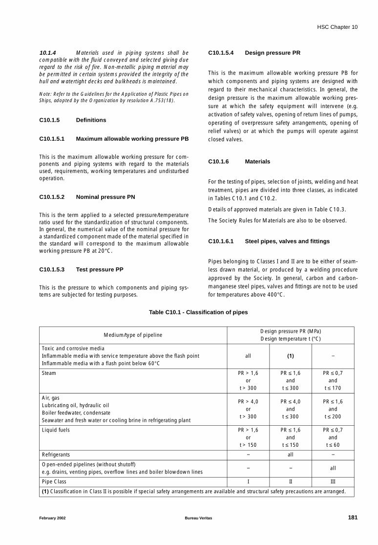
HSC Chapter 10
10.1.4 Materials used in piping systems shall becompatible with the fluid conveyed and selected giving dueregard to the risk of fire. Non-metallic piping material maybe permitted in certain systems provided the integrity of thehull and watertight decks and bulkheads is maintained.
Note: Refer to the Guidelines for the Application of Plastic Pipes onShips, adopted by the Organization by resolution A.753(18).
C10.1.5 Definitions
C10.1.5.1 Maximum allowable working pressure PB
This is the maximum allowable working pressure for com-ponents and piping systems with regard to the materialsused, requirements, working temperatures and undisturbedoperation.
C10.1.5.2 Nominal pressure PN
This is the term applied to a selected pressure/temperatureratio used for the standardization of structural components.In general, the numerical value of the nominal pressure fora standardized component made of the material specified inthe standard will correspond to the maximum allowableworking pressure PB at 20°C.
C10.1.5.3 Test pressure PP
This is the pressure to which components and piping sys-tems are subjected for testing purposes.
C10.1.5.4 Design pressure PR
This is the maximum allowable working pressure PB forwhich components and piping systems are designed withregard to their mechanical characteristics. In general, thedesign pressure is the maximum allowable working pres-sure at which the safety equipment will intervene (e.g.activation of safety valves, opening of return lines of pumps,operating of overpressure safety arrangements, opening ofrelief valves) or at which the pumps will operate againstclosed valves.
C10.1.6 Materials
For the testing of pipes, selection of joints, welding and heattreatment, pipes are divided into three classes, as indicatedin Tables C10.1 and C10.2.
Details of approved materials are given in Table C10.3.
The Society Rules for Materials are also to be observed.
C10.1.6.1 Steel pipes, valves and fittings
Pipes belonging to Classes I and II are to be either of seam-less drawn material, or produced by a welding procedureapproved by the Society. In general, carbon and carbon-manganese steel pipes, valves and fittings are not to be usedfor temperatures above 400°C.
Table C10.1 - Classification of pipes
Medium/type of pipelineDesign pressure PR (MPa)Design temperature t (°C)
Toxic and corrosive mediaInflammable media with service temperature above the flash pointInflammable media with a flash point below 60°C
all (1) −
Steam PR > 1,6or
t > 300
PR ≤ 1,6and
t ≤ 300
PR ≤ 0,7and
t ≤ 170
Air, gasLubricating oil, hydraulic oilBoiler feedwater, condensateSeawater and fresh water or cooling brine in refrigerating plant
PR > 4,0or
t > 300
PR ≤ 4,0and
t ≤ 300
PR ≤ 1,6and
t ≤ 200
Liquid fuels PR > 1,6or
t > 150
PR ≤ 1,6and
t ≤ 150
PR ≤ 0,7and
t ≤ 60
Refrigerants − all −
Open-ended pipelines (without shutoff)e.g. drains, venting pipes, overflow lines and boiler blowdown lines
− − all
Pipe Class I II III
(1) Classification in Class II is possible if special safety arrangements are available and structural safety precautions are arranged.
February 2002 Bureau Veritas 181

HSC Chapter 10
Table C10.2 - Approved materials and types of material certificates
C10.1.6.2 Pipes, valves and fittings of aluminiumand aluminium alloy
Aluminium and aluminium alloys are to comply with Soci-ety Rules for Materials and may be used for temperatures upto 200°C.Pipes made of aluminium may be used for the followingservices:
• Fresh cooling water systems
• Bilge systems outside areas of major fire hazard, asdefined in 7.3.1
• Air and sounding pipes; for air and sounding pipes oftanks containing flammable liquids outside of major firehazard areas, as defined in 7.3.1
• Pipes containing flammable liquids outside areas ofmajor fire hazards, as defined in 7.3.1
• Pipes for non-essential services.Seawater cooling pipes and ballast pipes and other seawaterpipes made of aluminium alloys, may be accepted at thediscretion of the Society.
C10.1.6.3 Pipes, valves and fittings of non-metallicmaterials
Pipes, connecting pieces, valves and fittings made of plasticmaterials may be used at the discretion of the Society.
Note: Plastic pipes and the application are to comply with IMOResolution A 753(18).
Plastic pipes are to be permanently marked with the follow-ing particulars:
• Manufacturer's marking
• Standard specification number
• Outside diameter and wall thickness
• Year of manufacture.
Valves and connecting pieces made of plastic shall, as aminimum requirement, be marked with the manufacturer'smarking and the nominal diameter.
C10.1.6.4 Pipes, valves and fittings of copper andcopper alloys
Pipes of copper and copper alloys are to be of seamlessdrawn material, or produced by a method approved by theSociety. Copper pipes for Classes I and II are to be seamless.
In general, copper and copper alloy pipelines are not to beused for media having temperatures above the followinglimits:
• Copper and aluminium brass: 200°C
• Copper nickel alloys: 300°C
• High-temperature bronze: 260°C.
Pipe Class
Type of component Approved materialDesign tem-
peratureSubject to testing
Type of certificate (EN 10204)
3.1.C (3) 3.1.B (3) 2.2 (4)
I + II
Pipes, pipe elbows, fittings
Steel, Copper,Copper alloy
− all x − −
Valves, flanges, metal expansion joints and hoses, other components
Steel,Cast steel > 300°C
DN > 32 x − −
DN ≤ 32 − x −
Steel,Cast steel,Nodular cast iron
≤ 300°C
PB x DN > 250or
DN ≥ 250x − −
PB x DN ≤ 250or
DN ≤ 250− x −
Copper,Copper alloy > 225°C
DN > 32 x − −
DN ≤ 32 − x −
≤ 225°CPB x DN > 150 x − −
PB x DN ≤ 150 − x −
IIIPipes, valves (2), flanges, other com-ponents
Steel, Cast steel,Grey cast iron (1),Nodular cast iron,Copper, Copper alloy
− − − − x
(1) No material test in the case of grey cast iron.(2) Casings of valves and pipe branches fitted on ship sides are to be included in pipe class II.(3) Inspection certificate.(4) Test report.
182 Bureau Veritas February 2002
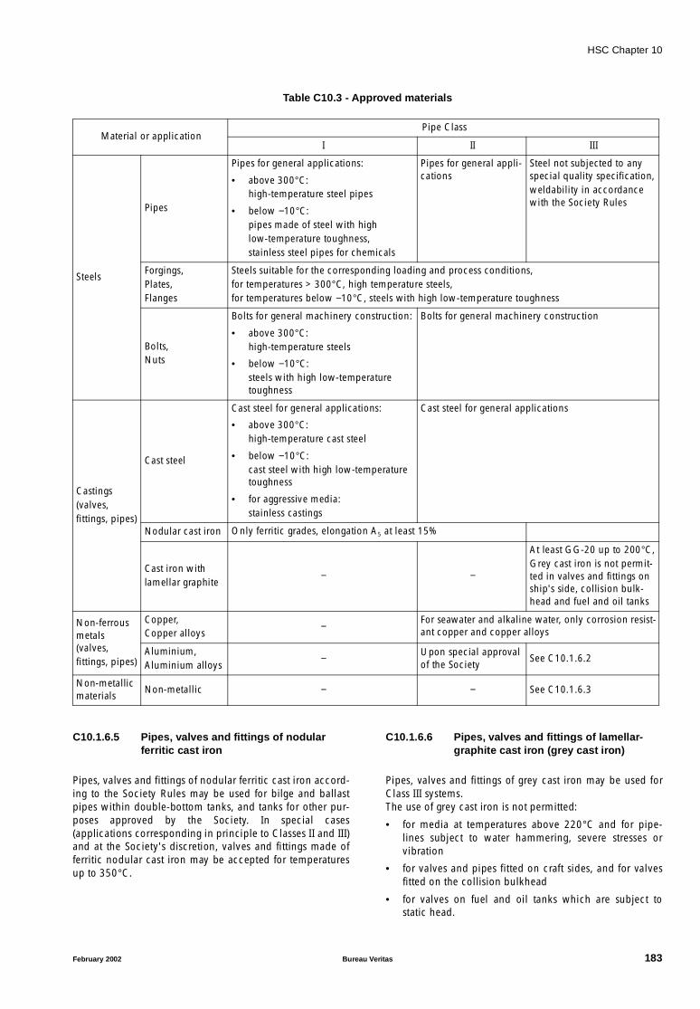
HSC Chapter 10
Table C10.3 - Approved materials
C10.1.6.5 Pipes, valves and fittings of nodularferritic cast iron
Pipes, valves and fittings of nodular ferritic cast iron accord-ing to the Society Rules may be used for bilge and ballastpipes within double-bottom tanks, and tanks for other pur-poses approved by the Society. In special cases(applications corresponding in principle to Classes II and III)and at the Society's discretion, valves and fittings made offerritic nodular cast iron may be accepted for temperaturesup to 350°C.
C10.1.6.6 Pipes, valves and fittings of lamellar-graphite cast iron (grey cast iron)
Pipes, valves and fittings of grey cast iron may be used forClass III systems.The use of grey cast iron is not permitted:
• for media at temperatures above 220°C and for pipe-lines subject to water hammering, severe stresses orvibration
• for valves and pipes fitted on craft sides, and for valvesfitted on the collision bulkhead
• for valves on fuel and oil tanks which are subject tostatic head.
Material or applicationPipe Class
I II III
Steels
Pipes
Pipes for general applications:
• above 300°C:high-temperature steel pipes
• below −10°C:pipes made of steel with highlow-temperature toughness,stainless steel pipes for chemicals
Pipes for general appli-cations
Steel not subjected to any special quality specification,weldability in accordance with the Society Rules
Forgings,Plates,Flanges
Steels suitable for the corresponding loading and process conditions,for temperatures > 300°C, high temperature steels,for temperatures below −10°C, steels with high low-temperature toughness
Bolts,Nuts
Bolts for general machinery construction:
• above 300°C:high-temperature steels
• below −10°C:steels with high low-temperature toughness
Bolts for general machinery construction
Castings(valves,fittings, pipes)
Cast steel
Cast steel for general applications:
• above 300°C:high-temperature cast steel
• below −10°C:cast steel with high low-temperature toughness
• for aggressive media:stainless castings
Cast steel for general applications
Nodular cast iron Only ferritic grades, elongation A5 at least 15%
Cast iron withlamellar graphite
− −
At least GG-20 up to 200°C,Grey cast iron is not permit-ted in valves and fittings on ship's side, collision bulk-head and fuel and oil tanks
Non-ferrous metals (valves,fittings, pipes)
Copper,Copper alloys
−For seawater and alkaline water, only corrosion resist-ant copper and copper alloys
Aluminium,Aluminium alloys
− Upon special approval of the Society
See C10.1.6.2
Non-metallic materials
Non-metallic − − See C10.1.6.3
February 2002 Bureau Veritas 183

HSC Chapter 10
C10.1.7 Testing
C10.1.7.1 Testing of materials
Pipes, bends, fittings, valve bodies and flanges for pipingsystems belonging to Classes I and II are subject to tests inaccordance with the Society Rules for Materials under theSociety's supervision.
C10.1.7.2 Testing prior to installation on board
.1 All Class I and II piping as well as all pipingfor compressed air and flammable liquids with a designpressure PR greater than 0,35 MPa are, after completion ofmanufacture but before insulation and coating, to be sub-jected to a hydraulic pressure test in the presence of aSurveyor at a pressure of 1,5⋅PR.When technical reasons do not allow complete hydraulicpressure tests on all pre-fabricated pipe sections beforeassembly on board, proposals are to be submitted forapproval to the Society.
.2 When hydraulic pressure tests of piping arecarried out on board, they may be conducted in conjunc-tion with the tests required under C10.1.7.3.
.3 Pressure testing of pipes with nominal diam-eters less than 15 mm may be omitted, at the Society'sdiscretion, pending the application.
C10.1.7.3 Testing after installation on board
.1 After assembly on board, all piping coveredby these Rules is to be subjected to a tightness test in pres-ence of a Surveyor.
In general, all pipe systems are to be tested for leakageunder operational conditions. If necessary, alternative teststo hydraulic pressure tests may be applied.
.2 Heating coils in tanks and piping for flamma-ble liquids are to be tested at a pressure of 1,5 PR, but in nocase at less than 0,4 MPa.
C10.1.7.4 Testing of valves
Valves are to be subjected to a hydraulic pressure and tight-ness test in the manufacturer's works, in presence of aSurveyor:
• Valves of pipe Classes I and II to 1,5 PR
• Valves and connections in the ship's side to not lessthan 0,5 MPa.
C10.1.8 Minimum wall thickness
C10.1.8.1 Minimum pipe thicknesses are stated inTable C10.4 to Table C10.10. These minimum thicknessesmay be increased if considered necessary, following stressanalysis.Slight differences in diameters and wall thicknesses basedon recognized standards may be accepted.Provided that pipes are effectively protected against corro-sion, the wall thicknesses of group M steel pipes may, at thediscretion of the Society, be reduced by up to 1 mm. Theamount of the reduction is to be in relation to the wallthickness.Protective coatings (e.g. hot-dip galvanizing) may be recog-nized as effective corrosion protection provided that itspreservation during installation is guaranteed.
Table C10.4 - Choice of minimum wall thickness for steel pipes
Pipingsystem
Location
Machin-ery
spaces
Cofferdam / void spaces
Cargo holds
Ballast water tanks
Fuel and changeover
tanks
Fresh cooling water tanks
Lubricat-ing
oil tanks
Hydraulic oil tanks
Drinking water tanks
Living quarters
Weather deck
Bilge lines
M
M
M
−
−
X
X X
X
M −
Ballast lines
M
X
N
Seawater lines
M
Fuel lines
N
− N
XLubricating lines
−
X X
N
NHydraulic lines
−
Drinking water lines
M X X
N
NFresh coolingwater lines
N X
Note: M, N: Refer to Table C10.6; X: Pipelines are not to be installed; (−): Pipelines may be installed by special agreement with the Society.
184 Bureau Veritas February 2002
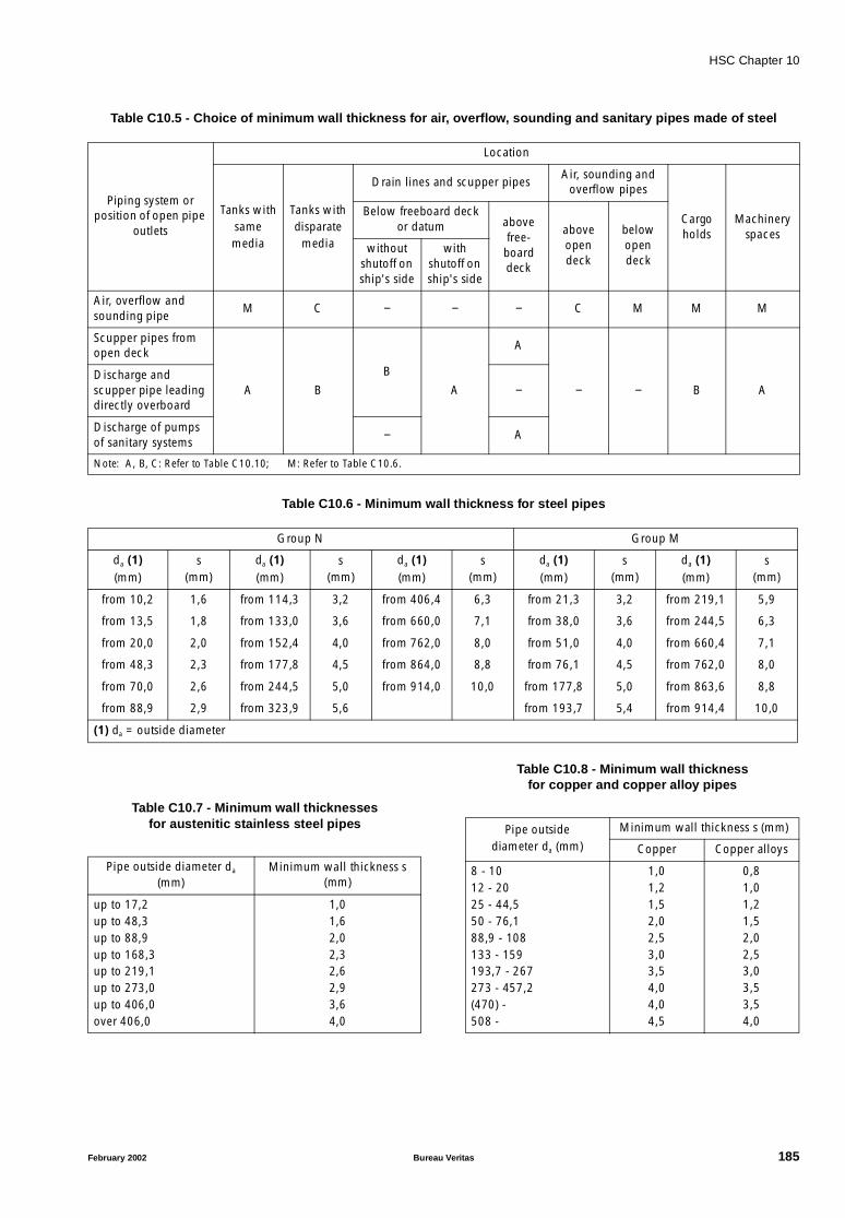
HSC Chapter 10
Table C10.5 - Choice of minimum wall thickness for air, overflow, sounding and sanitary pipes made of steel
Table C10.6 - Minimum wall thickness for steel pipes
Table C10.7 - Minimum wall thicknessesfor austenitic stainless steel pipes
Table C10.8 - Minimum wall thicknessfor copper and copper alloy pipes
Piping system or position of open pipe
outlets
Location
Tanks withsamemedia
Tanks withdisparate
media
Drain lines and scupper pipesAir, sounding and
overflow pipes
Cargo holds
Machinery spaces
Below freeboard deck or datum above
free-board deck
above open deck
below open deck
without shutoff on ship's side
with shutoff on ship's side
Air, overflow and sounding pipe
M C − − − C M M M
Scupper pipes from open deck
A B
B
A
A
− − B ADischarge and scupper pipe leading directly overboard
−
Discharge of pumps of sanitary systems
− A
Note: A, B, C: Refer to Table C10.10; M: Refer to Table C10.6.
Group N Group M
da (1)(mm)
s(mm)
da (1)(mm)
s(mm)
da (1)(mm)
s(mm)
da (1)(mm)
s(mm)
da (1)(mm)
s(mm)
from 10,2 1,6 from 114,3 3,2 from 406,4 6,3 from 21,3 3,2 from 219,1 5,9
from 13,5 1,8 from 133,0 3,6 from 660,0 7,1 from 38,0 3,6 from 244,5 6,3
from 20,0 2,0 from 152,4 4,0 from 762,0 8,0 from 51,0 4,0 from 660,4 7,1
from 48,3 2,3 from 177,8 4,5 from 864,0 8,8 from 76,1 4,5 from 762,0 8,0
from 70,0 2,6 from 244,5 5,0 from 914,0 10,0 from 177,8 5,0 from 863,6 8,8
from 88,9 2,9 from 323,9 5,6 from 193,7 5,4 from 914,4 10,0
(1) da = outside diameter
Pipe outside diameter da (mm)
Minimum wall thickness s (mm)
up to 17,2up to 48,3up to 88,9up to 168,3up to 219,1up to 273,0up to 406,0over 406,0
1,01,62,02,32,62,93,64,0
Pipe outsidediameter da (mm)
Minimum wall thickness s (mm)
Copper Copper alloys
8 - 1012 - 2025 - 44,550 - 76,188,9 - 108133 - 159193,7 - 267273 - 457,2(470) -508 -
1,01,21,52,02,53,03,54,04,04,5
0,81,01,21,52,02,53,03,53,54,0
February 2002 Bureau Veritas 185
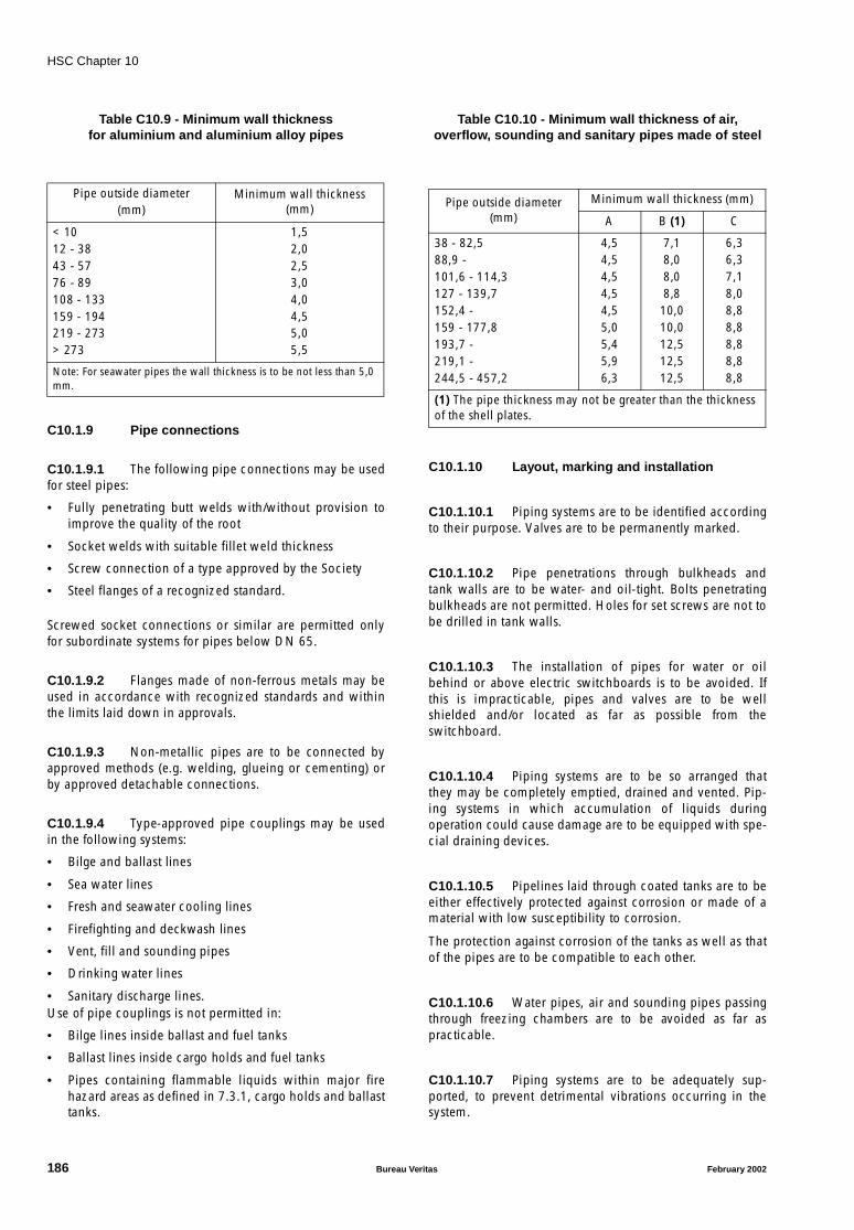
HSC Chapter 10
Table C10.9 - Minimum wall thicknessfor aluminium and aluminium alloy pipes
C10.1.9 Pipe connections
C10.1.9.1 The following pipe connections may be usedfor steel pipes:
• Fully penetrating butt welds with/without provision toimprove the quality of the root
• Socket welds with suitable fillet weld thickness
• Screw connection of a type approved by the Society
• Steel flanges of a recognized standard.
Screwed socket connections or similar are permitted onlyfor subordinate systems for pipes below DN 65.
C10.1.9.2 Flanges made of non-ferrous metals may beused in accordance with recognized standards and withinthe limits laid down in approvals.
C10.1.9.3 Non-metallic pipes are to be connected byapproved methods (e.g. welding, glueing or cementing) orby approved detachable connections.
C10.1.9.4 Type-approved pipe couplings may be usedin the following systems:
• Bilge and ballast lines
• Sea water lines
• Fresh and seawater cooling lines
• Firefighting and deckwash lines
• Vent, fill and sounding pipes
• Drinking water lines
• Sanitary discharge lines.Use of pipe couplings is not permitted in:
• Bilge lines inside ballast and fuel tanks
• Ballast lines inside cargo holds and fuel tanks
• Pipes containing flammable liquids within major firehazard areas as defined in 7.3.1, cargo holds and ballasttanks.
Table C10.10 - Minimum wall thickness of air,overflow, sounding and sanitary pipes made of steel
C10.1.10 Layout, marking and installation
C10.1.10.1 Piping systems are to be identified accordingto their purpose. Valves are to be permanently marked.
C10.1.10.2 Pipe penetrations through bulkheads andtank walls are to be water- and oil-tight. Bolts penetratingbulkheads are not permitted. Holes for set screws are not tobe drilled in tank walls.
C10.1.10.3 The installation of pipes for water or oilbehind or above electric switchboards is to be avoided. Ifthis is impracticable, pipes and valves are to be wellshielded and/or located as far as possible from theswitchboard.
C10.1.10.4 Piping systems are to be so arranged thatthey may be completely emptied, drained and vented. Pip-ing systems in which accumulation of liquids duringoperation could cause damage are to be equipped with spe-cial draining devices.
C10.1.10.5 Pipelines laid through coated tanks are to beeither effectively protected against corrosion or made of amaterial with low susceptibility to corrosion.
The protection against corrosion of the tanks as well as thatof the pipes are to be compatible to each other.
C10.1.10.6 Water pipes, air and sounding pipes passingthrough freezing chambers are to be avoided as far aspracticable.
C10.1.10.7 Piping systems are to be adequately sup-ported, to prevent detrimental vibrations occurring in thesystem.
Pipe outside diameter(mm)
Minimum wall thickness (mm)
< 1012 - 3843 - 5776 - 89108 - 133159 - 194219 - 273> 273
1,52,02,53,04,04,55,05,5
Note: For seawater pipes the wall thickness is to be not less than 5,0 mm.
Pipe outside diameter (mm)
Minimum wall thickness (mm)
A B (1) C
38 - 82,588,9 -101,6 - 114,3127 - 139,7152,4 -159 - 177,8193,7 -219,1 -244,5 - 457,2
4,54,54,54,54,55,05,45,96,3
7,18,08,08,8
10,010,012,512,512,5
6,36,37,18,08,88,88,88,88,8
(1) The pipe thickness may not be greater than the thickness of the shell plates.
186 Bureau Veritas February 2002
HSC Chapter 10
C10.1.11 Valves
C10.1.11.1 Shutoff devices
Shutoff devices are to comply with a recognized standard.Valves with screwed-on covers are to be secured, to preventinadvertent loosening of the cover.Hand-operated shutoff devices are to be closed by turningin a clockwise direction.Valves are to be clearly marked to show whether they areopen or closed.
C10.1.11.2 Craft side valves
.1 Craft side valves are to be easily accessibleand capable of being operated from above the floor.Where, subject to C10.1.6.2 and C10.1.6.3, sea water pipesmade of aluminium alloys or non-metallic materials areaccepted by the Society, craft's side valves inside machineryspaces and other spaces with major fire hazard are to beprovided with means of remote closure from outside thespace.
.2 Valves are to be of a flanged type and madeof metallic ductile material.
.3 The minimum wall thickness of pipebranches connected to the craft's hull below the datumshall be as follows:
• for steel pipes: in accordance with Table C10.10,Group B
• for aluminium pipes: at least 8 mm but not greater thanthe thickness of the shell plate.
C10.1.11.3 Remote-controlled valves
.1 General
For remote-controlled valves, failure of power supply is notto cause:
• opening of closed valves
• closing of open valves on fuel tanks and in coolingwater systems for propulsion and power generatingmachinery.
Remote-controlled valves are to be equipped with an emer-gency operating arrangement.They are to be accessible for maintenance and repair work.
.2 Power units
Power units for remote-controlled valves are to be equippedwith at least two independent power supply units.For the closing of valves which are not closed by springaction, power units are to be fitted with pressureaccumulators.Pneumatically operated valves may be supplied by air fromthe general compressed air system.
.3 Control station
At the control station, means are to be provided to showwhether the valves are open or closed.For visual indication of the closed position of valves, limit-position indicators approved by the Society are to beprovided.The control position is to be located in a space which isnormally attended, e.g. operating compartment.
.4 Bilge piping
Valves and control lines for bilge systems are to be locatedas far as possible from the bottom and side shell of the craft.
.5 Fuel pipes
Valves mounted directly at fuel tanks above the double bot-tom are to be capable of being closed from outside thecompartment in which they are installed (e.g. from craft'soperating compartment or other suitable locations).
C10.1.12 Hose assemblies and compensators ofnon-metallic materials
C10.1.12.1 Requirements
Hose assemblies and compensators of non-metallic mate-rial are to be type-approved and tested according to theSociety Rules.Hose assemblies and compensators including their cou-plings are to be suitable for media, pressures andtemperatures.Selection of hose assemblies and compensators is to bebased on the maximum allowable working pressure of thesystem concerned. 0,5 MPa is to be considered as the mini-mum working pressure.
C10.1.12.2 Installation
Hose assemblies are not to be longer than necessary for theapplication.The minimum bending radius is not to be less than theradius specified by the manufacturer.Hose assemblies and compensators are to be accessible.Hoses used in fresh water systems with workingpressures ≤ 0,5 MPa, or in charging air and scavenging airducts, may be fastened with double clips. Hoses which areinstalled directly near hot surfaces are to be provided withadditional heat-resistant sheathing.
C10.1.13 Pumps
C10.1.13.1 General
Construction, materials and tests of pumps are to complywith the Society Rules.
February 2002 Bureau Veritas 187
HSC Chapter 10
C10.1.13.2 Relief valves
Positive displacement pumps are to be fitted with reliefvalves which cannot be adjusted to the closed position.They are to discharge into the suction side of the pump.
C10.1.13.3 Tests
The pumps listed below are subject to tests carried out atthe manufacturer's works, under the Society supervision:
• Fire pumps and emergency fire pumps
• Bilge pumps
• Seawater cooling pumps
• Fresh water cooling pumps
• Fuel transfer pumps
• Fuel service pumps
• Fuel injection valve cooling pumps
• Lubricating oil pumps
• Ballast pumps
• Boiler feedwater pumps
• Boiler water circulating pumps
• Other pumps considered necessary for performance ofessential functions.
10.2 Arrangement of oil fuel,lubricating oil and otherflammable oil
10.2.1 The provisions of 7.1.2.2 apply to the use ofoil as fuel.
C10.2.1 The requirements stipulated in 7.5 are to becomplied with.
10.2.2 Oil fuel, lubricating oil and other flammableoil lines shall be screened or otherwise suitably protected toavoid, as far as practicable, oil spray or oil leakages onto hotsurfaces, into machinery air intakes or other sources of igni-tion. The number of joints in such piping systems shall bekept to a minimum. Flexible pipes carrying flammable liq-uids shall be of an approved type.
Note: Refer to the Guidelines to Minimize Leakages from Flamma-ble Liquid Systems for Improving Reliability and Reducing Risk ofFire (MSC/Circ. 647).
C10.2.2(a) As far as practicable, flammable liquid linesare not to be arranged in the vicinity of boilers, turbines orequipment with surface temperatures greater than 220°C,nor above electrical equipment.
C10.2.2(b) Pumps are to be provided with shutoffvalves.
C10.2.2(c) Filling pipes for tanks containing flammableliquids are to terminate on open deck and be arranged sothat leakages are collected by suitable coamings.
Fuel-oil filling connections are, as far as practicable, to bearranged on both sides of the craft.
10.2.3 Fuel oil, lubricating oils and other flammableoils shall not be carried forward of public spaces and crewaccommodation.
C10.2.3
C10.2.3.1 All tanks not forming part of the craft struc-ture are to be fastened securely and arranged so that theycan be readily inspected.Free-standing fuel tanks are to be installed so as to allowfree circulation of air around the tanks.
Fuel tanks for emergency diesel generators are to be locatedinside the emergency generator room.
C10.2.3.2 Appliances, mountings and fittings not form-ing part of the fuel tank equipment may be fitted to tankwalls only by means of intermediate supports. Only compo-nents forming part of the tank equipment may be fitted tofreestanding tanks.
For valves and pipe connections, the tank walls are to beprovided with strengthening flanges. Bolt holes are not tobe drilled in tank surfaces.Instead of strengthening flanges, short, thick pipe flangeconnections may be welded to the tank surfaces.
10.2.4 Oil fuel arrangements
In a craft in which oil fuel is used, the arrangements for thestorage, distribution and utilization of the oil fuel shall besuch as to ensure the safety of the craft and persons onboard and shall at least comply with the followingprovisions.
10.2.4.1 As far as practicable, all parts of the oil fuelsystem containing heated oil under pressure exceeding 0,18N/mm2shall not be placed in a concealed position such thatdefects and leakage cannot readily be observed. Themachinery spaces in way of such parts of the oil fuel systemshall be adequately illuminated.
C10.2.4.1 Fuel lines are not to pass through tanks con-taining feedwater, drinking water or lubricating oil.
10.2.4.2 The ventilation of machinery spaces shall besufficient under all normal conditions to prevent accumula-tion of oil vapour.
C10.2.4.2 The provisions of Art. 10.6 and Art. 10.7 areto be complied with.
188 Bureau Veritas February 2002

HSC Chapter 10
10.2.4.3 Location of fuel tanks shall be in accordancewith 7.5.2 .
C10.2.4.3 Fuel tanks are to be separated by voids/cof-ferdams from tanks containing lubricating, hydraulic,thermal or edible oil and drinking water.
Fuel service tanks inside machinery spaces are to be madeof steel.
10.2.4.4 No oil fuel tank shall be situated where spill-age or leakage therefrom can constitute a hazard by fallingon heated surfaces. Reference is made to the fire safetyrequirements in Art. 7.5.
10.2.4.5 Oil fuel pipes shall be fitted with cocks orvalves in accordance with 7.5.3.
C10.2.4.5(a) The controls of such valves are to be locatedoutside the space in which the tanks are arranged, as far aspossible combined in one location, preferably the craft'soperating compartment.
C10.2.4.5(b) Valves subject to static head are to be madeof ductile material.
C10.2.4.5(c) Remote-controlled shutoff valves may be dis-pensed with for tanks with a capacity of less than 50 litres.
10.2.4.6 Every fuel tank shall, where necessary, beprovided with savealls or gutters to catch any fuel whichmay leak from such tanks.
C10.2.4.6 Tanks located above the double bottom areto be fitted with self-closing drains.
10.2.4.7 Safe and efficient means of ascertaining theamount of oil fuel contained in any oil fuel tank shall beprovided.
10.2.4.7.1 Where sounding pipes are used they shallnot terminate in any space where the risk of ignition of spill-age from the sounding pipe might arise. In particular, theyshall not terminate in public spaces, crew accommodationor machinery spaces. Terminations shall be provided with asuitable means of closure and provision to prevent spillageduring refuelling operations.
10.2.4.7.2 Other oil-level gauges may be used in placeof sounding pipes. Such means are subject to the followingconditions:
.1 In passenger craft, such means shall notrequire penetration below the top of the tank and their fail-ure or overfilling of the tanks will not permit release of fuel.
.2 The use of cylindrical gauge glasses shall beprohibited. In cargo craft, the Society may permit the use ofoil-level gauges with flat glasses and self-closing valvesbetween the gauges and fuel tanks. Such other means shallbe acceptable to the Society and shall be maintained in theproper condition to ensure their continued accurate func-tioning in service.
C10.2.4.7.3 Level-indicating devices which are not type-approved by the Society may be accepted if sounding pipesare provided in addition.
Sight glasses and oil gauges fitted directly on the tank wall,and cylindrical glass gauges, are not permitted.
C10.2.4.7.4 Sounding pipes are to terminate outsidemain fire hazard areas and as far as possible above the opendeck. However, where this is not possible, the followingrequirements are to be met:
• Oil-level gauges are to be provided in addition tosounding pipes.
• Sounding pipes are either to terminate in locationsremote from ignition hazards or to be fitted with effec-tive screens to prevent spillages coming into contactwith a source of ignition.
• Sounding pipes are to be fitted with self-closing shutoffdevices and self-closing testing devices.
10.2.4.8 Provision shall be made to prevent overpres-sure in any oil tank or in any part of the fuel system,including the filling pipes. Any relief valves and air or over-flow pipes shall discharge to a safe position and, for fuel offlashpoint less than 43°C, shall terminate with flame arrest-ers in accordance with the standards developed by theOrganization.
Note: Refer to the Revised Standards for the Design, Testing andLocating of Devices to Prevent the Passage of Flame into CargoTanks in Tankers (MSC/Circ. 677).
C10.2.4.8 Lines of relief/safety valves and overflowlines are to discharge into leakage, drain or overflow tanks.
10.2.4.9 Oil fuel pipes and their valves and fittingsshall be of steel or other approved material, except thatrestricted use of flexible pipes shall be permissible in posi-tions where the Society is satisfied that they are necessary(see Note). Such flexible pipes and end attachments shallbe of approved fire-resisting materials of adequate strengthand shall be constructed to the satisfaction of theAdministration.
Note: Refer top recommendations published by the InternationalOrganization for Standardization, in particular Publications:
- ISO 15540:1999 on Test methods for fire resistance of hoseassemblies, and
- ISO 15541:1999 on Requirements for the test bench of fireresistance of hose assemblies.
February 2002 Bureau Veritas 189
HSC Chapter 10
10.2.5 Lubricating oil arrangements
The arrangements for the storage, distribution and utilisa-tion of oil used in pressure lubrication systems shall be suchas to ensure the safety of the craft and persons on board.The arrangements made in machinery spaces and, when-ever practicable, in auxiliary machinery spaces shall at leastcomply with the provisions of 10.2.4.1 and 10.2.4.4 to10.2.4.8 except that:
.1 this does not preclude the use of sight-flowglasses in lubricating systems provided they are shown bytest to have a suitable degree of fire resistance;
.2 sounding pipes may be permitted in machin-ery spaces if fitted with appropriate means of closure; and
.3 lubricating oil storage tanks with a capacityof less than 500 l may be permitted without remote oper-ated valves as required in 10.2.4.5.
C10.2.5(a) Flexible pipes are permissible in positionswhere the Society is satisfied that they are necessary. Suchflexible pipes and end attachments in pressure lubricatingsystems located in machinery spaces and auxiliary machin-ery spaces as defined in Chapter 7 are to be of approvedfire-resistant material of adequate strength and constructedto the satisfaction of the Society.
C10.2.5(b) Lubricating oil systems are to be constructedto ensure reliable lubrication over the whole range of speedand during run-down of the engines, and are to ensure ade-quate heat transfer.
C10.2.5(c) Independent standby pumps are to be pro-vided for propulsion engines. For craft with more than onemain engine, each provided with an independent lubricat-ing oil system, standby pumps are not required.Engines and gears fitted with attached pumps are to be pro-vided with an independent auxiliary lubricating pump iflubrication before starting is necessary.
C10.2.5(d) Equipment for suitable treatment of lubricat-ing oil (e.g. purifiers, automatic back-flushing filters, filters,free-jet centrifuges) are to be provided.
.1 Lubricating oil filters are to be fitted in pumppressure lines.Uninterrupted supply of filtered oil has to be ensured undermaintenance conditions of filter equipment. Mesh size andfilter capacity are to be in accordance with the engine man-ufacturer's requirements.
.2 Main filters are to be provided with differen-tial pressure monitoring.Back-flushing cycles of automatic filters are also to bemonitored.
.3 Engines for emergency power supply oremergency fire pumps may be provided with simplex filters.
10.2.6 Arrangements for other flammable oils
The arrangements for storage, distribution and utilisation ofother flammable oils employed under pressure in powertransmission systems, control and activating systems andheating systems shall be such as to ensure the safety of thecraft and persons on board. In locations where means ofignition are present, such arrangements shall at least complywith the provisions of 10.2.4.4 and 10.2.4.7 and with theprovisions of 10.2.4.8 and 10.2.4.9 in respect of strengthand construction.
C10.2.6 The provisions of 10.2.4.6, 10.2.5.2 and10.2.5.3 are to be complied with where applicable, as wellas the provisions of 10.2.4.9 in respect of the approval ofthe fire-resistant materials of flexible pipes.
10.2.7 Arrangements within machinery spaces
In addition to the requirements of 10.2.1 to 10.2.6, the oilfuel and lubricating oil systems shall comply with thefollowing:
10.2.7.1 Where daily service fuel tanks are filled auto-matically or by remote control, means shall be provided toprevent overflow spillages.
C10.2.7.1 Service tanks are to be fitted with high- andlow-level alarms.
10.2.7.2 Other equipment which treats flammable liq-uids automatically, such as oil fuel purifiers, which,whenever practicable, shall be installed in a special spacereserved for purifiers and their heaters, shall have arrange-ments to prevent overflow spillages.
C10.2.7.2 Purifiers for cleaning fuel and lubricating oilare to be in accordance with Society Rules.
10.2.7.3 Where daily service oil fuel tanks or settlingtanks are fitted with heating arrangements, a high tempera-ture alarm shall be provided if the flashpoint of the oil canbe reached due to failure of the thermostatic control.
C10.2.7.3 Tanks which require preheating are to be fit-ted with temperature-indicating devices and, wherenecessary, thermal insulation.Heating coils are to be provided with shutoff valves at tankinlet and outlet. Heating coils are also to be fitted at thetank outlet with an upstream device to test the condensate.Heating coil connections in tanks are to be welded.Heating coils are to be supported in such a way as not to besubjected to non-allowable stresses due to vibration, partic-ularly at their points of clamping.Further requirements concerning heating systems (e.g.boiler, piping layout) are to be taken into consideration.
190 Bureau Veritas February 2002
HSC Chapter 10
10.3 Bilge pumping and drainagesystems
10.3.1 Arrangements shall be made for draining anywatertight compartment other than the compartmentsintended for permanent storage of liquid. Where in relationto particular compartments drainage is not considered nec-essary, drainage arrangements may be omitted but it shallbe demonstrated that the safety of the craft will not beimpaired.
C10.3.1(a) Bilge suctions are to be suitably arrangedand fitted with mud boxes.
C10.3.1(b) Every machinery space is normally to be pro-vided with at least two bilge suctions, one at each side.Additional suctions may be required for craft having longmachinery spaces.
C10.3.1(c) Bilge suctions are to be arranged so as not toimpede the cleaning of bilges and bilge wells.
10.3.2 Bilge pumping arrangements shall be pro-vided to allow every watertight compartment other thanthose intended for permanent storage of liquid to bedrained. The capacity or position of any such compartmentshall be such that flooding thereof could not affect thesafety of the craft.
10.3.3 The bilge pumping system shall be capableof operation under all possible values of list and trim afterthe craft has sustained the postulated damage in 2.6.6 and2.6.10. The bilge pumping system shall be so designed as toprevent water flowing from one compartment to another.The necessary valves for controlling the bilge suctions shallbe capable of being operated from above the datum. Alldistribution boxes and manually operated valves in connec-tion with the bilge pumping arrangements shall be in posi-tions which are accessible under ordinary circumstances.The spindles of manually operated valves shall be easilyaccessible and all valves shall be clearly marked.
C10.3.3(a) Valves in pipe connections between bilgeand seawater or ballast water systems, as well as betweenbilge connections of different compartments, are to bearranged so that even in the event of faulty operation orintermediate positions of the valves, seawater is safely pre-vented from penetrating through the bilge system.
C10.3.3(b) To prevent penetration of ballast and seawa-ter into the ship through the bilge system, two means ofreverse-flow protection are to be fitted in the bilge connec-tions, one of which is to be a screw-down non-return valve.One such means of protection is to be fitted in each branchline.For emergency and direct suctions, one screw-down non-return valve is sufficient.
C10.3.3(c) A combination of a non-return valve withpositive closing device and shutoff valve may be recognizedas equivalent to a screw-down non-return valve, at the dis-cretion of the Society.
C10.3.3(d) Discharges below the datum are to be pro-vided with shutoff valves located at the shell.
10.3.4 The power operated self-priming bilgepumps may be used for other duties such as fire fighting orgeneral service but not for pumping fuel or other flammableliquids.
C10.3.4(a) In the event of pump failure, one pump forfire fighting and one pump for bilge pumping are to remainavailable.
C10.3.4(b) Bilge ejectors are acceptable for bilge pump-ing arrangements if an independent supply of driving wateris provided.
10.3.5 Each power bilge pump shall be capable ofpumping water through the required bilge pipe at a speedof not less than 2 m/sec.
10.3.6 The diameter (d) of the bilge main shall becalculated according to the following formula, except thatthe actual internal diameter of the bilge main may berounded off to the nearest size of a recognized standard:
d = 25 + 1,68 (L (B + D))0,5
where:
d : Internal diameter of the bilge main, in mm
L : Length of the craft, in m, as defined in Chapter 1
B : For monohull craft: breadth of the craft, in m, asdefined in Chapter 1
For multi-hull craft: breadth of a hull at or belowthe design waterline, in m
D : Moulded depth of the craft to the datum, in m.
10.3.7 Internal diameters of suction branches shallmeet the requirements of the Society but shall not be lessthan 25 mm. Suction branches shall be fitted with effectivestrainers.
C10.3.7 The diameter is given by the formula:
dB = 25 + 2,15 (LB(B1 + d))0,5
where:
dB : Internal diameter, in mm, of the branch pipes
LB : Length, in m, of the watertight compartment
B1 : Average breadth, in m, of the compartment at orbelow the design waterline.
February 2002 Bureau Veritas 191
HSC Chapter 10
10.3.8 An emergency bilge suction shall be pro-vided for each machinery space containing a propulsionprime mover. This suction shall be led to the largest availa-ble power pump other than a bilge pump, propulsion pumpor oil pump.Emergency bilge suctions shall be provided for craft withcommon bilge pumping systems according to 10.3.6 andfor craft with individual bilge pumps according to 10.3.13.
C10.3.8(a) Emergency bilge suctions are to be arrangedin an accessible position, at a suitable distance from thedouble bottom ceiling or the craft bottom. The position is toallow the free flow of bilge water.The diameter is to be equal to the diameter of the suctionline of the pump.
C10.3.8(b) Emergency bilge valves and the suctionvalves of the relevant pumps are to be capable of beingoperated from above the floor.
10.3.9 The spindles of the sea inlet valves shallextend well above the machinery space floor plates.
C10.3.9 The provisions of C10.1.11.2 are to be com-plied with.
10.3.10 All bilge suction piping up to the connectionto the pumps shall be independent of other piping.
10.3.11 Spaces situated above the water level in theworst anticipated damage conditions may be draineddirectly overboard through scuppers fitted with non-returnvalves.
10.3.12 Any unattended space for which bilge pump-ing arrangements are required shall be provided with a bilgealarm.
C10.3.12 Each machinery space is normally to be pro-vided with at least two bilge alarms.
10.3.13 For craft with individual bilge pumps, thetotal capacity Q of the bilge pumps for each hull shall notbe less than 2,4 times the capacity of the pump defined in10.3.5 and 10.3.6.
10.3.14 In bilge pumping arrangements where a bilgemain is not provided, then, with the exception of the spacesforward of public spaces and crew accommodation, at leastone fixed submersible pump shall be provided for eachspace. In addition, at least one portable pump shall be pro-vided supplied from the emergency supply, if electric, foruse on individual spaces. The capacity of each submersiblepump Qn shall not be less than:Qn = Q / (N − 1) ton/h with a minimum of 8 tons/hwhere:
N : Number of submersible pumps
Q : Total capacity as defined in 10.3.13.
10.3.15 Non-return valves shall be fitted in the fol-lowing components:
.1 bilge valve distribution manifolds;
.2 bilge suction hose connections where fitteddirectly to the pump or to the main bilge suction pipe; and
.3 direct bilge suction pipes and bilge pumpconnections to main bilge suction pipe.
C10.3.15 For reverse-flow protections, see C10.3.3.2and C10.3.3.3.
C10.3.16 Arrangements for oily bilge water and oilresidues
Each craft is to be provided with at least:
• a collecting tank for oily bilge water, fuel and oilresidues
• equipment for discharge of oil residues to receptionfacilities.
Note: MARPOL 73/78 as amended and national requirements areto be observed.
10.4 Ballast systems
10.4.1 Water ballast shall not in general be carriedin tanks intended for oil fuel. In craft in which it is not prac-ticable to avoid putting water in oil fuel tanks, oily-waterseparating equipment shall be fitted, or other alternativemeans such as discharge to shore facilities shall be providedfor disposing of the oily-water ballast. The provisions of thisparagraph are without prejudice to the provisions of theInternational Convention for the Prevention of Pollutionfrom Ships in force.
10.4.2 Where a fuel transfer system is used for bal-last purposes, the system shall be isolated from any waterballast system and meet the requirements for fuel systemsand the International Convention for the Prevention of Pol-lution from Ships in force.
C10.4.3 Piping layout
Where pipes are led through the collision bulkhead, a shut-off valve, made of ductile metallic material, is to be fitteddirectly at the collision bulkhead.The valve is to be capable of being closed by remote controlfrom the operating compartment.
192 Bureau Veritas February 2002

HSC Chapter 10
10.5 Cooling systems
The cooling arrangements provided shall be adequate tomaintain all lubricating and hydraulic fluid temperatureswithin the manufacturers' recommended limits during alloperations for which the craft is to be certificated.
C10.5.1 General
Cooling water circuits are to be provided with temperaturecontrols in accordance with the requirements of Chapter11. Control devices whose failure may impair the functionalreliability of the system are to be equipped for manualoperation.
C10.5.2 Cooling water pumps
C10.5.2.1 Main and standby cooling water pumps areto be provided for propulsion systems with one mainengine, or systems with more than one engine using a com-mon cooling water system.
For propulsion plants with more than one engine, and forauxiliary engines provided with individual cooling circuits,standby pumps may be dispensed with.
C10.5.2.2 Standby cooling water pumps shall be drivenindependently.
C10.5.3 Heat exchangers, coolers
C10.5.3.1 For common cooling systems, the numberand capacity of heat exchangers and coolers is to be con-sidered by the Society.
C10.5.3.2 Heat exchangers and coolers are to be pro-vided with:
• shutoff valves at inlet and outlet
• vents and drains.
C10.5.4 Keel coolers
Keel coolers are to be fitted with pressure gauges at thefresh water inlet and outlet.
C10.5.5 Seawater cooling systems
C10.5.5.1 At least two sea inlets are to be provided.
Wherever possible, sea chests are to be provided and posi-tioned as low as possible on either side of the craft.
On multi-hull craft or craft with independent engine rooms,one sea chest or sea inlet for each hull or engine room isconsidered sufficient.
C10.5.5.2 Each sea chest is to be provided with aneffective vent and a connection to flush the sea chest grat-ings. The flushing media may not exceed the constructionpressure of the sea chest.
C10.5.5.3 The suction lines of seawater pumps are tobe fitted with strainers.Strainers are to be arranged so that they can be cleanedwhile the pumps are in operation.For multiple-engine installations, single strainers are consid-ered sufficient.
C10.5.6 Sea valves
The provisions of C10.1.11.2 are to be complied with.Discharge pipes for seawater cooling systems are to be fit-ted with a shutoff valve at the shell. If discharges are locatedabove the datum, shutoff valves may be dispensed with.
C10.5.7 Fresh water cooling systems
C10.5.7.1 Where heat exchangers for fuel or lubricat-ing oil are incorporated in cylinder cooling water circuits ofpropulsion engines, the entire cooling water circuit is to bemonitored for fuel and oil contamination.
C10.5.7.2 Expansion tanks are to be fitted with fillingconnections, aeration/de-aeration devices, water level indi-cators and drains.
C10.5.7.3 Means are to be provided for preheating asrequired.
10.6 Engine air intake systems
Arrangements shall provide sufficient air to the engine andshall give adequate protection against damage as distinctfrom deterioration, due to ingress of foreign matter.
C10.6.1 The provisions of Art. 7.6 of Chapter 7 and ofArt. 10.7, if relevant, are to be complied with.
10.7 Ventilation systems
Machinery spaces shall be adequately ventilated so as toensure that, when machinery therein is operating at fullpower in all weather conditions including heavy weather,an adequate supply of air is maintained to the spaces for thesafety and comfort of personnel and the operation of themachinery. Auxiliary machinery spaces shall be adequatelyventilated appropriate for the purpose of those spaces. Theventilation arrangements shall be adequate to ensure thatthe safe operation of the craft is not put at risk.
February 2002 Bureau Veritas 193

HSC Chapter 10
C10.7.1 The provisions of Art. 7.6 of Chapter 7 are tobe complied with.
C10.7.2 Each independent machinery space is to beprovided with its own ventilation system.
In general, ventilation systems for machinery spaces are tobe independent of each other.
C10.7.3 The height of the coamings from the inletand outlet openings is, as far as practicable, to comply withthe requirements of LLC 66, and in no case be less than thedatum.
If water traps are to be provided, air velocity is to be takeninto account.
C10.7.4 The air is to be conducted in such a way as toavoid local accumulations of heat wherever possible (e.g.by means of a secondary system of selective ventilation orby under-floor ducting of exhaust air).
C10.7.5 The air supply is not to be directed immedi-ately towards hot machine parts, turbine components,measuring instruments or switchboards. Electrical machin-ery and installations (e.g. switch cabinets) are to beprotected, so that water particles penetrating into air ductswill not cause damage. Risks of this kind are to be mini-mized by appropriate arrangement of ducts and air outlets.
C10.7.6 The capacity and arrangement of ventilationsystems/ducts is to ensure that accumulation of oil vapour isavoided and a slight overpressure in the machinery spaceduring normal operation is guaranteed.
Provision is to be made to remove CO2, in case of floodingof the machinery space.
C10.7.7 Ventilation capacity is to be based on theheat radiation of equipment installed in the space.
10.8 Exhaust systems
10.8.1 All engine exhaust systems shall be adequateto assure the correct functioning of the machinery and thatsafe operation of the craft is not put at risk.
C10.8.1 Exhaust pipes are to be installed separatelyfrom each other, taking structural fire protection intoaccount.
Account is to be taken of thermal expansion when layingout and suspending lines.
Exhaust lines and silencers are to be provided with suitabledrains of adequate size.
10.8.2 Exhaust systems shall be so arranged as tominimize the intake of exhaust gases into manned spaces,air-conditioning systems, and engine intakes. Exhaust sys-tems shall not discharge into air cushion intakes.
10.8.3 Pipes through which exhaust gases are dis-charged through the hull in the vicinity of the waterline shallbe fitted with erosion/corrosion resistant shuttoff flaps orother devices on the shell or pipe end and acceptablearrangements made to prevent water flooding the space orentering the engine exhaust manifold.
C10.8.3(a) Shutoff flaps may be omitted if the overflowpoint of the exhaust pipe is located above the most unfa-vourable damage water line.
Shutoff devices are to be fitted with means for remote con-trolled closing above the datum, preferably from theoperating compartment. The closed position is to beindicated.
C10.8.3(b) The use of flexible hoses in wet exhaust sys-tems may be accepted at the discretion of the Society, if thehoses are suitable for this purpose (media, pressure andtemperature).
C10.8.3(c) Materials used in exhaust systems are to beresistant to sea water corrosion and exhaust products.
10.8.4 Gas turbine engine exhausts shall bearranged so that hot exhaust gases are directed away fromareas to which personnel have access, either on board thecraft or in the vicinity of the craft when berthed.
C10.8.5 Insulation
Exhaust lines, silencers and exhaust gas boilers are to beinsulated properly.
Insulating materials are to be incombustible.
Exhaust lines inside engine rooms are to be provided withmetal sheathing or other approved type of hard sheathing.
C10.A.1 Compressed air systems
C10.A.1.1 Starting equipment
Starting equipment (e.g. air compressors and air receivers)are to comply with Art. 9.3 of Chapter 9 for gas turbines andArt. 9.4 of Chapter 9 for diesel engines.
194 Bureau Veritas February 2002
HSC Chapter 10
C10.A.1.2 Compressed air lines
Pressure lines connected to air compressors are to be fittedwith non-return valves at the compressor outlets.
Oil and water separators are to be provided.
The starting air line to each engine is to be fitted with a non-return device and drain.
A safety valve is to be fitted behind each pressure-reducingvalve.
The compressed air supply for blowing through sea chestsmay not exceed the design pressure of the sea chest (seeC10.5.5.2).
C10.A.1.3 Control air system
Control air systems for essential consumers are to be pro-vided with the necessary means of air treatment.
C10.A.2 Steam heating, feedwater andcondensate systems
C10.A.2.1 General
For steam and hot water generators as well as for oil-firedburners, the provision of 9.1.13 of Chapter 9 are to be com-plied with.
Pipes, pumps and valves belonging to these systems are alsosubject to the following requirements.
C10.A.2.2 Steam lines
Steam lines are to be installed and supported so thatexpected stresses due to thermal expansion, external loadsand shifting of the supporting structure under both normaland interrupted service conditions will be safely compen-sated. Sufficiently rigid positions are to be arranged as fixedpoints for the steam piping systems. Steam lines are to beprovided with sufficient expansion arrangements.
Steam lines are to be installed so that water pockets will beavoided. Means are to be provided for reliable drainage ofthe piping system.
Steam lines are to be effectively insulated to prevent heatlosses. Pipe penetrations through bulkheads and decks areto be insulated to prevent heat conduction. At points wherethere is a possibility of contact, the surface temperature ofthe insulated steam lines may not exceed 60°C. Wherevernecessary, additional protection arrangements against unin-tended contact are to be provided.
C10.A.2.3 Feedwater lines
Feedwater lines are to be fitted with shutoff valves andcheck valves at the boiler inlet. Where shutoff and checkvalves are not directly connected in series, the intermediatepipe is to be fitted with a drain.
Feedwater pumps are to be fitted with shutoff valves on thesuction side and screw-down non-return valves on thedelivery side. The pipes are to be arranged so that eachpump can supply each feedwater line.
Provision of only one feedwater line for auxiliary andexhaust gas boilers is sufficient if the preheaters and auto-matic regulating devices are fitted with bypass lines.
Continuous-flow boilers need not be fitted with thesevalves, provided that the heating of the boiler is automati-cally switched off if the feedwater supply fails, and that thefeedwater pump supplies only one boiler.
Feedwater lines may not pass through tanks which do notcontain feedwater.
C10.A.2.4 Capacity of feedwater pumps
Provision of only one feedwater pump is sufficient if theboiler is not intended for essential services.
Where two feedwater pumps are provided, the capacity ofeach is to be equivalent to at least 1,25 times the maximumpermitted output of all the connected steam producers.
Where more than two feedwater pumps are installed, thecapacity of all other feedwater pumps, in the event of fail-ure of the pump with the largest capacity, is to comply withthe requirements above.
For continuous-flow boilers, the capacity of the feedwaterpumps is to be at least 1,0 times the maximum steamoutput.
Special conditions may be accepted for the capacity of thefeedwater pumps, for plants incorporating a combination ofoil-fired and exhaust-gas boilers or other arrangements.
C10.A.2.5 Boiler water circulating systems
The provision of only one circulating pump for each boileris sufficient in the following cases:
• boilers are heated only by gases whose temperaturedoes not exceed 400°C, or
• a common standby circulating pump is provided, whichcan be connected to any boiler,
• the burners of oil- or gas-fired auxiliary boilers arearranged so that they are automatically shut off if thecirculating pump fails and the heat stored in the boilerdoes not cause any unacceptable evaporation of theavailable water in the boiler,
• the boiler is not intended for essential services.
February 2002 Bureau Veritas 195

HSC Chapter 10
C10.A.2.6 Condensate recirculation
The condensate of all heating systems used to heat oil (e.g.fuel, lubricating, cargo oil) is to be led to condensate obser-vation tanks. These tanks are to be fitted with vents to theopen deck.
C10.A.3 Air, overflow and sounding pipes
C10.A.3.1 General
The minimum wall thickness for steel pipes is to be inaccordance with Table C10.5, Table C10.6 and TableC10.10.
The minimum wall thickness for pipes in material other thansteel shall be at least:
• in accordance with Tables C10.7, C10.8 or C10.9below the open deck
• increased by at least 50% above the open deck.All compartments and tanks arranged with filling and/ordrainage equipment are to be fitted with air pipes andsounding devices.
C10.A.3.2 Air and overflow pipes
Voids, cofferdams and tanks are to be fitted with air pipes.The arrangement is to allow total filling of tanks under nor-mal trim conditions.Air pipes located on open deck are to be fitted with auto-matic air pipe heads approved by the Society at a height notlower than 760 mm above deck.
Note: Refer to International Convention on Load Lines, 1966 Reg.20 (LLC66) as amended.
Air pipes of tanks which contain fuel oil are to terminate onopen deck to save locations with no risk of ignition (see also10.2.4.8).
Air pipes of tanks which contain liquids other than fuel oilmay terminate inside closed spaces. Means are to be pro-vided for safe drainage in the event of overflow.
Air pipes of integral tanks located at the shell side are to ter-minate above the datum.Air and overflow pipes are to be arranged in such a way thatthey are self-draining under normal conditions.Where air and overflow pipes of several tanks are con-nected to a common line, the common line andconnections are to be arranged so that, if a leakage occursin one tank due to hull damage or listing of the ship, fuel orwater cannot flow into another tank.
The minimum inner diameter of air/overflow pipes is not tobe less than 40 mm.The clear cross-sectional area of air/overflow pipes is to beat least 1,25 times the cross-sectional area of the fillingpipes. However, pump capacity and pressure head are to beconsidered in sizing air and overflow pipes.
C10.A.3.3 Sounding pipes
Sounding pipes are to be provided for tanks, cofferdamsand void spaces and bilge wells in spaces which are notaccessible at all times. As far as possible, sounding pipesare to be laid straight and are to extend as near as possibleto the bottom of the tank close to the pump suction.
Sounding pipes may not be used as filling pipes.
Where tanks are fitted with remote level indicatorsapproved by the Society, provision of sounding pipes maybe dispensed with.
Sounding pipes which terminate below the datum are to befitted with self-closing shutoff devices. Such sounding pipesare permissible only in spaces which are accessible at alltimes. All other sounding pipes are to be extended to theopen deck. Sounding pipe openings are always to be acces-sible and fitted with watertight closing devices.
Sounding pipes for tanks which contain flammable liquidsare to extend to the open deck, or comply with the require-ments of Art. 7.5 of Chapter 7 and 10.2.4.7.
Sounding pipes are to have a nominal inside diameter of atleast 32 mm.
C10.A.4 Drinking water systems
Note: Any national rules are to be observed.
Drinking water systems are to comply with the SocietyRules.
C10.A.5 Sanitary systems
C10.A.5.1 General arrangement
Sanitary discharge pipes are to be arranged so that, in theevent of damage, undamaged compartments cannot beflooded by damaged discharge lines, even if the craftinclines temporarily.
Where discharge lines from several watertight compart-ments are connected to one tank, the compartments are tobe separated from each other by gate or ball valves at thewatertight bulkheads. Valves shall be capable of beingclosed by remote control from the craft operating compart-ment or another space above the datum. An indicator forthe closed position is to be provided among the controls.
The minimum wall thicknesses of sanitary discharge pipesare to be determined in accordance with Table C10.5 andTable C10.10. Penetrations of pipes of smaller thickness,pipes of special types and plastic pipes through bulkheadsor decks of type A fire integrity require Society approval.
Overboard discharges are to be fitted with means of pre-venting ingress of water from the sea. The Load LineConvention (LLC) as amended is to be applied analogously.
196 Bureau Veritas February 2002
HSC Chapter 10
C10.A.5.2 Sewage tanks and sewage treatmentsystems
Sewage tanks are to be fitted with air pipes leading to theopen deck above the datum.Sewage tanks are to be fitted with a filling connection, aconnection for flushing the tank and a level alarm. Existingoverflows to the bilge or openings for adding of chemicalsare considered as internal openings.The discharge lines of sewage tanks below the datum are tobe fitted with a non-return valve and a gate valve. The gatevalve is to be fitted directly at the craft's shell.A single screw-down non-return valve may be used insteadof the gate and non-return valves.The second means of reverse-flow protection may be a pipeloop with an overflow height which remains above thewater level in the worst anticipated damage condition. Thepipe loop is to be fitted with an automatic ventilationdevice located 45° below the crest of the loop.Ballast and bilge pumps may not be used for emptying sew-age tanks.
C10.A.6 Hydraulic systems for hatchcovers, shell closing appliances,watertight doors and hoists
C10.A.6.1 General
Cylinders are preferably to be made of steel, cast steel ornodular cast iron (with a predominantly ferritic matrix).For cylinders, where PB⋅∆i > 2000, materials are to be testedin accordance with the Society Rules (Di being the insidediameter, in mm).Testing of materials by the Society may be dispensed with inthe case of cylinders for secondary applications, providedthat evidence in the form of a works test certificate (e.g. toEN 10 204 - 2.3) is supplied.For testing the materials of hydraulic accumulators, seeChapter 9.
C10.A.6.2 Hydraulic operating equipment for hatchcovers
C10.A.6.2.1 Design and construction
Hydraulic operating equipment for hatch covers may beserved either by a common power station for all hatch cov-ers or by several power stations individually assigned to asingle hatch cover. Where a common power station is used,at least two pump units are to be fitted. Where the systemsare supplied individually, changeover valves or fittings arerequired so that operation can be maintained if one pumpunit fails.Movement of hatch covers may not be initiated by startingof the pumps. Special control stations are to be provided tocontrol the opening and closing of hatch covers. Controlsare to be so designed that, as soon as they are released,movement of the hatch covers stops immediately.
Hatches are normally to be visible from control stations. If,in exceptional cases, this is impossible, opening and closingof the hatches are to be signalled by an audible alarm. Inaddition, the control stations are then to be equipped withindicators to monitor movements of the hatch covers.
At control stations, the controls governing opening andclosing operations are to be appropriately marked.
Suitable equipment is to be fitted in, or immediately adja-cent to, each power unit (cylinder or similar) used tooperate hatch covers, to enable the hatches to be closedslowly in the event of a power failure (e.g. due to a piperupture).
Hatch covers are to be fitted with devices which preventthem from moving into their end positions at excessivespeed. Such devices are not to cause the power unit to beswitched off.
C10.A.6.2.2 Pipes
Pipe dimensions are to be calculated according to the Soci-ety Rules.
Piping systems are to be fitted with filters to clean thehydraulic fluid.
Equipment is to be provided to enable the hydraulic systemsto be vented.
The accumulator space of the hydraulic accumulator is tohave permanent access to the relief valve of the connectedsystem. The gas chamber of the accumulator may be filledonly with inert gases. Gas and operating media are to beseparated by accumulator bags, diaphragms or similardevices.
Connection between the hydraulic systems used for hatchcover operation and other hydraulic systems is permittedonly at the discretion of the Society.
Tanks forming part of the hydraulic system are to be fittedwith oil-level indicators.
C10.A.6.2.3 Emergency operation
Devices shall be fitted that are independent of the main sys-tem and which enable hatch covers to be opened andclosed in the event of failure of the main system. Suchdevices may, for example, take the form of loose rings ena-bling hatch covers to be moved by cargo winches, warpingwinches etc.
C10.A.6.3 Hydraulically operated closingappliances in the craft's shell
C10.A.6.3.1 Scope
The following requirements apply to the power equipmentof hydraulically operated closing appliances in the craft'sshell, such as shell and landing doors which are not nor-mally operated while at sea.
February 2002 Bureau Veritas 197
HSC Chapter 10
C10.A.6.3.2 Design and construction
The movement of doors and other closing devices in theshell may not be initiated by starting of the pumps at thepower station.
Local control, inaccessible to unauthorized persons, is to beprovided for every closing appliance in the craft's shell. Assoon as the controls (push-buttons, levers or similar) arereleased, movement of the appliance is to be stoppedimmediately.
Closing appliances in the craft's shell are normally to be vis-ible from control stations. If the movement cannot beobserved, audible alarms are to be fitted. In addition, con-trol stations are to be equipped with indicators enabling themovement to be monitored.
Closing appliances in the craft's shell are to be fitted withdevices which prevent them from moving into their endpositions at excessive speed. Such devices are not to causethe power unit to be switched off.
As far as necessary, mechanical means are to be provided tolock closing appliances in the open position.
Every power unit driving horizontally hinged or verticallyoperated closing appliances is to be fitted with throttlevalves or similar devices, to prevent sudden dropping of theclosing appliance.
Driving power shall be shared between at least two mutu-ally independent pump units.
For pipes see C10.A.6.2.2.
C10.A.6.4 Hydraulic operating systems forwatertight doors
Requirements concerning these items are given inChapter 2.
C10.A.6.5 Hoists
C10.A.6.5.1 Scope
For the purposes of these requirements, hoists includehydraulically operated appliances such as wheelhousehoists, lifts and similar equipment.
C10.A.6.5.2 Design and construction
Hoists may be operated either by a combined power stationor by individual power stations.
In the case of a combined power supply, with hydraulicdrive pipes connected to other hydraulic systems, a secondpump unit is to be fitted.
The movement of hoists is not to be initiated merely bystarting the pumps. The movement is to be controlled fromspecial operating stations. Controls are to be so arrangedthat, as soon as they are released, the movement of the hoiststops immediately.
Local controls, inaccessible to unauthorized persons, are tobe fitted. The movement of hoists is normally to be visiblefrom the operating stations. If the movement cannot beobserved, audible and/or visual warning devices are to befitted. In addition, operating stations are to be equippedwith indicators to monitor the movement of the hoist.
Devices are to be fitted which prevent the hoist from reach-ing its end position at excessive speed. Such devices are notto cause the power unit to be switched off. As far as neces-sary, mechanical means are to be provided to lock the hoistin its end positions.
Suitable equipment is to be fitted in, or immediately adja-cent to, each power unit used to operate hoists to enablethem to be lowered slowly if the power unit fails or a piperuptures.
For pipes see C10.A.6.2.2.
C10.A.6.6 Tests at the manufacturer's works
C10.A.6.6.1 Testing of power units
Power units are to undergo testing on a test bed. Factory testcertificates for this testing are to be submitted at finalinspection of the hydraulic system.
C10.A.6.6.2 Pressure and tightness tests
Pressure components are to undergo a pressure test at testpressure PP = 1,5⋅PR.
For the definitions of the PP and PR see C10.1.5.3 andC10.1.5.4. However, for maximum working pressuresabove 20 MPa, the test pressure need not exceed PR + 10MPa.
For pressure testing of pipes, their valves and fittings, seeC10.1.7.
Tightness tests are to be performed on components forwhich this is appropriate.
C10.A.6.6.3 Function tests
Watertight doors are to be subjected to a functional testwith an adverse list of 15°.
C10.A.6.6.4 Shipboard trials
After installation, the equipment is to undergo an opera-tional test.
Operational testing of watertight doors is to include theemergency operating system and measurement of closingtimes.
198 Bureau Veritas February 2002
HSC Chapter 10
Part B Requirements for passenger craft
10.9 Bilge pumping and drainagesystems
10.9.1 For category B craft at least three and for cat-egory A craft at least two power bilge pumps shall be fittedconnected to the bilge main, one of which may be drivenby the propulsion machinery. Alternatively, the arrangementmay be in accordance with the requirements of 10.3.14.
10.9.2 The arrangements shall be such that at leastone power bilge pump shall be available for use in all flood-ing conditions which the craft is required to withstand asfollows:
.1 one of the required bilge pumps shall be anemergency pump of a reliable submersible type having anemergency source of power; or
.2 the bilge pumps and their sources of powershall be so distributed throughout the length of the craft thatat least one pump in an undamaged compartment will beavailable.
C10.9.2 The “emergency source” is to be locatedabove the datum.
10.9.3 On multi-hull craft, each hull shall be pro-vided with at least two bilge pumps.
10.9.4 Distribution boxes, cocks and valves in con-nection with the bilge pumping system shall be so arrangedthat, in the event of flooding, one of the bilge pumps maybe operative in any compartment. In addition, damage to apump or its pipe connecting to the bilge main shall not putthe bilge system out of action. When, in addition to themain bilge pumping system, an emergency bilge pumpingsystem is provided, it shall be independent of the main sys-tem and so arranged that a pump is capable of operating inany compartment under flooding conditions as specified in10.3.3. In that case only the valves necessary for the opera-tion of the emergency system need be capable of beingoperated from above the datum.
10.9.5 All cocks and valves referred to in 10.9.4which can be operated from above the datum shall havetheir controls at their place of operation clearly marked andshall be provided with means to indicate whether they areopen or closed.
C10.9.5 The control station for remote-controlledvalves shall be located in the operating compartment as faras possible.
C10.B.1 Operating systems for watertightdoors
Requirements concerning these items are given inChapter 2.
Part C Requirements for cargo craft
10.10 Bilge pumping systems
10.10.1 At least two power pumps connected to themain bilge system shall be provided, one of which may bedriven by the propulsion machinery. If the Administration issatisfied that the safety of the craft is not impaired, bilgepumping arrangements may be dispensed with in particularcompartments. Alternatively, the arrangement may be inaccordance with the requirements of 10.3.14.
10.10.2 On multi-hull craft each hull shall be pro-vided with at least two power pumps, unless a bilge pumpin one hull is capable of pumping bilge in the other hull. Atleast one pump in each hull shall be an independent powerpump.
C10.C.1 Hydraulic operating systems forwatertight doors
Requirements concerning these items are given inChapter 2.
February 2002 Bureau Veritas 199

HSC Chapter 11
CHAPTER 11 REMOTE CONTROL, ALARM AND SAFETY SYSTEMS
C11.0 Documents to be submitted
C11.0.1 The following drawings and documents areto be submitted in triplicate for approval. The Societyreserves the right to ask for supplementary copies if deemednecessary in particular cases.
.1 Layout diagrams showing the location ofindividual components, input and output devices, controlcabinets and interconnection lines between thecomponents;
.2 Wiring and piping diagrams including detailsof their material and connecting units;
.3 Plans and specification showing the workingprinciples of the system with comprehensive description;
.4 List of instruments stating name of manufac-turers, types, working ranges, set points and applicationwith regard to their environmental conditions;
.5 Plans of control and monitoring panels withdetails on their instrumentation and control devices;
.6 List of operating values of machinery andlimits for alarm and safety action threshold;
.7 Diagrams of electric and non-electric powersupply;
.8 System analysis of programmable electronicsystems including hardware configuration, algorithms and−on special request− data structure and storage allocations;FMEA documentation as required in Annex 4 where manualintervention for averting of a danger is not possible;
.9 Testing programmes of the equipment in themanufacturer's works and on dock and sea trial.
C11.0.2 Further documentation may be required ifdeemed necessary by the Society.
11.1 Definitions
11.1.1 “Remote control systems” comprise allequipment necessary to operate units from a control posi-tion where the operator cannot directly observe the effectof his actions.
11.1.2 “Back-up control systems” comprise allequipment necessary to maintain control of essential func-tions required for the craft's safe operation when the maincontrol systems have failed or malfunctioned.
11.2 General
11.2.1 Failure of any remote or automatic controlsystems shall initiate an audible and visual alarm and shallnot prevent normal manual control.
11.2.2 Manoeuvring and emergency controls shallpermit the operating crew to perform the duties for whichthey are responsible in a correct manner without difficulty,fatigue or excessive concentration.
C11.2.2 The operation of the remote control from thecraft's operation station is to be so designed and con-structed that it does under normal conditions not requirethe operator's particular attention of the details of themachinery.
The remote control systems consisting of steel cable links orequivalent are to be submitted to the Society for specialconsideration.
The equipment, to which this Chapter applies, shall be ofstate of the art design and construction and shall haveproved their reliability in marine service. If evidence on therequired reliability cannot be given by relevant documenta-tion, the equipment has to be subjected to an approvalaccording to the Rules of the Society.
11.2.3 Where control of propulsion or manoeuvringis provided at stations adjacent to but outside the operatingcompartment, the transfer of control shall only be effectedfrom the station which takes charge of control. Two-wayvoice communication shall be provided between all stationsfrom which control functions may be exercised andbetween each such station and the look-out position. Fail-ure of the operating control system or of transfer of controlshall bring the craft to low speed without hazarding passen-gers or the craft.
C11.2.3 Under normal conditions, the transfer of thecontrol function between such control positions may onlybe effected if the respective control devices are in the sameposition or if equivalent means are provided for smoothtransfer of command without significant change in thecraft’s speed and direction of thrust.
200 Bureau Veritas February 2002
HSC Chapter 11
11.2.4 For category B craft and cargo craft, remotecontrol systems for propulsion machinery and directionalcontrol shall be equipped with back-up systems controllablefrom the operating compartment. For cargo craft, instead ofa back-up system described above, a back-up system con-trollable from an engine control space, such as an enginecontrol room outside the operating compartment, isacceptable.
C11.2.4 If provided so, the communication ofmachinery propulsion orders shall be effected by a tele-graph system or equivalent means, which imply an opticalindication at the such control positions of the machineryorders received from the craft's operating station.
C11.2.5 Under all sailing conditions (includingmanoeuvring), the propulsion machinery, including propel-lers, jets, flaps or other means which affect the speed anddirection of thrust of all category high speed craft, is to becontrollable from the craft's operating station.
C11.2.6 In principle the remote control is to be per-formed by a single control device for each independentpropulsion unit with automatic performance of all associ-ated services including, where necessary, means ofpreventing overload and prolonged running in criticalspeed ranges of the propulsion unit.In cases where multiple propulsion units are designed tooperate simultaneously, the command on their controlsshall be designed for the possibility of being connected inone control device, in order to select individual or commoncontrol of the units, as necessary for the appropriate modeof operation.Movement of the control device shall take place in thesame direction as the desired motion of the ship.
C11.2.7 Each control position is to be provided withmeans to indicate which of them is in control.At any control position, from which control of craft'smanoeuvring is exercised, the operating effects caused bycontrol inputs to the propulsion unit shall continuously beindicated.
C11.2.8 After restoration of normal conditions follow-ing an automatic shut-down, the machinery shall not startinadvertently before the control device has been reset tostop. Following an automatic slow-down−if provided−thepropulsion of the craft shall not accelerate inadvertentlybefore the control device has been reset to the actual step ofspeed, to which the power of the propulsion had beendecreased.Alternatively, other arrangements may be provided for theoperator to consciously admit starting or acceleration ofpropulsion machinery.Remote starting of a propulsion unit is to be automaticallyinhibited if conditions exist which may hazard the machin-ery, e.g. turning gear engaged, clutch engaged, shut-downactivated, etc.
C11.2.9 The power for the control system is to besupplied from the same source which supplies the essentialservices for the propulsion units. As an alternative, thepower for the control system may be supplied from othersources of power with backing-up facilities, which are suffi-cient for at least 15 minutes operation of the control system,in case of failure in its normal supply.
In case of category B craft, the control system of each pro-pulsion unit shall have its individual source of power.
11.3 Emergency controls
11.3.1 In all craft, the station or stations in the oper-ating compartment from which control of craftmanoeuvring and/or of its main machinery is exercised shallbe provided, within easy reach of the crew member at thatstation, with controls for use in an emergency to:
.1 activate fixed fire-extinguishing systems;
.2 close ventilation openings and stop ventilat-ing machinery supplying spaces covered by fixed fire-extinguishing systems, if not incorporated in .1;
.3 shut off fuel supplies to machinery in mainand auxiliary machinery spaces;
.4 disconnect all electrical power sources fromthe normal distribution system (the operating control shallbe guarded to reduce the risk of inadvertent or carelessoperation); and
.5 stop main engine(s) and auxiliary machinery.
C11.3.1 Unless it is considered impracticable, a sin-gle failure of the emergency controls shall not have aninadvertent effect on the system which it serves. In case ofsuch a failure, an alarm shall be given in the craft's operat-ing compartment.
The stopping device for main engine(s) is to be independentfrom the remote control system at the craft's operatingstation.
11.3.2 Where control of propulsion and manoeu-vring is provided at stations outside the operatingcompartment, such stations shall have direct communica-tion with the operating compartment which shall be acontinuously manned control station.
11.3.3 In addition, for category B craft, control ofpropulsion and manoeuvring, as well as emergency func-tions referred to in 11.3.1, shall be provided in a stationoutside the operating compartment. Such stations shallhave direct communication with the operating compart-ment which shall be a continuously manned control station.
February 2002 Bureau Veritas 201

HSC Chapter 11
11.4 Alarm system
11.4.1 Alarm systems shall be provided whichannounce at the craft's control position, by visual and audi-ble means, malfunction or unsafe conditions. Alarms shallbe maintained until they are accepted and the visual indica-tions of individual alarms shall remain until the fault hasbeen corrected, when the alarm shall automatically reset tothe normal operating condition. If an alarm has beenaccepted and a second fault occurs before the first is recti-fied, the audible and visual alarms shall operate again.Alarm systems shall incorporate a test facility.
11.4.1.1 Emergency alarms giving indication of condi-tions requiring immediate action shall be distinctive and infull view of crew members in the operating compartment,and shall be provided for the following:
.1 activation of a fire detection system;
.2 total loss of normal electrical supply;
.3 overspeed of main engines;
.4 thermal runaway of any permanentlyinstalled nickel-cadmium battery.
C11.4.1.1 In addition to the alarms requested under11.4.1.1, the following alarms, giving indication that is dis-tinctive and in full view of crew members in the operatingcompartment, are to be provided:
.1 fire (alarm to summon the crew);
.2 general emergency alarm (alarm to summoncrew and passengers to muster stations);
.3 fire-extinguishing medium imminent release;
.4 watertight doors imminent closing, compart-ment flooding.
11.4.1.2 Alarms with a visual display distinct from thatof alarms referred to in 11.4.1.1 shall indicate conditionsrequiring action to prevent degradation to an unsafe condi-tion. These shall be provided for at least the following:
.1 exceeding the limiting value of any craft,machinery or system parameter other than engineoverspeed;
.2 failure of normal power supply to powereddirectional or trim control devices;
.3 operation of any automatic bilge pump;
.4 failure of compass system;
.5 low level of a fuel tank contents;
.6 fuel oil tank overflow;
.7 extinction of side, masthead or stern naviga-tion lights;
.8 low level of contents of any fluid reservoir thecontents of which are essential for normal craft operation;
.9 failure of any connected electrical powersource;
.10 failure of any ventilation fan installed for ven-tilating spaces in which inflammable vapours mayaccumulate;
.11 diesel engine fuel line failure as required by9.4.2.
C11.4.1.2 With reference to 11.4.1.2.1 in particular,the machinery is to be monitored in the scope as listed inTable C11.4.1.2.1 to Table C11.4.1.2.6.
Table C11.4.1.2.1 - Propulsion diesel engines
ParameterAlarm level
Remark
Lubricating oil pressure low
Lubricating oiltemperature inlet
high
Differential pressure across lubricating oil filter
high
Pressure or flow of cooling water
low
Temperature ofcooling water outlet
high
Level in cooling water expansion tank
low
Deviation of eachcylinder from average of exhaust gas temperature, or
high if cylinder power above 130 kW
Exhaust gas temperature of each cylinder
low + high
Exhaust gas temperature after turbocharger
high if cylinders not monitored indi-vidually and if cylinder power below 130 kW
Pressure of fuel oil to engine
low if supplied by electrical pumps
Temperature of fuel oil to engine
low + high if heated
Pressure of control air low
Pressure of starting air low
Safety system failure
202 Bureau Veritas February 2002
HSC Chapter 11
Table C11.4.1.2.2 - Propulsion gas turbines
Table C11.4.1.2.3 - Transmission, shaft gears
Table C11.4.1.2.4 - Main diesel generator sets
Table C11.4.1.2.5 - Auxiliary boilers
Table C11.4.1.2.6 - Miscellaneous
11.4.1.3 All warnings required by 11.4.1.1 and11.4.1.2 shall be provided at all stations at which controlfunctions may be exercised.
11.4.2 The alarm system shall meet appropriateconstructional and operational requirements for requiredalarms.
Note: Refer to the Code on Alarms and Indicators, 1995, adoptedby the Organization by resolution A.830(19).
11.4.3 Equipment monitoring the passenger, cargoand machinery spaces for fire and flooding shall, so far aspracticable, form an integrated sub-centre incorporatingmonitoring and activation controls for all emergency situa-tions. This sub-centre may require feed-back instrumenta-tion to indicate that actions initiated have been fully imple-mented.
C11.4.4 On category B craft, alarm systems includingtheir power supply have to be separate for each independ-ent propulsion unit and its essential auxiliaries.
11.5 Safety system
11.5.1 Where arrangements are fitted for overridingany automatic shut-down system for the main propulsionmachinery in accordance with 9.2.2, they shall be such asto preclude inadvertent operation.
Parameter Alarm level Remark
Lubricating oil pressure low
Lubricating oil temperature high
Differential pressure across lubri-cating oil filter
high
Bearing temperature high
Exhaust gas temperature outlet high
Vibrations high
Axial displacement high
Combustion/ignition failure
Hydraulic service oil pressure low
Safety system failure
Parameter Alarm level Remark
Lubricating oil pressure to gears low
Lubricating oil temperature of gears with sliding bears
high
Servo oil pressure of gears and transmissions
low
Thrust bearing temperature high
Stern tube temperature high
Parameter Alarm level Remark
Lubricating oil pressure low
Pressure or flow of cooling water low
Temperature of cooling water out-let
high
Starting power capacity low
Voltage low
Frequency low
Overspeed tripped
Safety system failure
Parameter Alarm level Remark
Water level low
Steam pressure low + high
Flame failure shut down
Safety system failure
Parameter Alarm level Remark
Remote control ofpropulsion
failure
Safety system of each machinery
tripped
Override of safetysystem
activated
Power of alarm system failure
Electrical non-essential consumers
tripped
Insulation resistance low
Emergency controls failure
Fire alarm system failure
Stand-by function of auxiliaries
start
Machinery space bilge level
high 2 sensors at least for each
machinery space
Fuel oil service tank temperature
high if heated above flash-point
Purifier failure
February 2002 Bureau Veritas 203

HSC Chapter 11
When a shut-down system is activated, an audible and vis-ual alarm shall be given at the control station and meansshall be provided to override the automatic shut-downexcept in cases where there is a risk of complete breakdownor explosion.
C11.5.1 In case of need, the bridge operator mayhave a possibility to cancel the safety devices which couldhave caused the propelling machinery to stop (except forthe overspeed one). Control of this device is to be such as topreclude inadvertent operation; the indication “safetydevices off” shall be clearly visible.
C11.5.2 After restoration of normal conditions follow-ing a shut-down, resetting of the safety system shall bepossible at the craft's operating station and at other posi-tions from which the control can be exercised.
C11.5.3 Safety systems are to be designed as far aspracticable to be independent of the alarm and control sys-tem and their power supply, such that a failure ormalfunction in these systems will not prevent the safety sys-tem from operating.Safety systems including their power supply shall be sepa-rate for each propulsion unit.
C11.5.4 Electrical circuits of safety systems for pro-pulsion machinery and essential systems, which in case oftheir failure have sudden effect on the availability of thepropulsion and directional control of the craft, shall be suchthat a single failure in the system does not result, as far aspracticable, in a loss of propulsion and directional control.The electrical circuits of safety systems for other machinery,which have no sudden effect on the availability of the pro-pulsion and steering, may be designed as suitable for theirpurpose with the most effective protection of the machinery.
C11.5.5 The power for the safety system shall be sup-plied from the main source of electrical power. Provisionsare to be made for supplying power uninterrupted to thesafety system for at least 15 minutes following a failure ofthe ship's main source of electrical power. The electric andpneumatic supplies are to be monitored.
C11.6 Stand-by systems
C11.6.1 Where stand-by units are required, they shallstart up automatically:
• on failure of operational units
• to preserve stored energy resources (e.g. compressedair)
• on operational demand, if auxiliary machinery are oper-ated in staggered service.
C11.6.2 The threshold for activation of the stand-bysystem shall be such that normal operation is restoredbefore the safety system is activated.
C11.6.3 The changeover to a stand-by unit due to afault is to be signalled visually and audibly. However, analarm is not to be tripped in the case of machinery installa-tions with auxiliary machines driven mechanically from thepropulsion plant where the stand-by machines start up auto-matically in the lower speed range.
C11.6.4 Sets which have suffered a malfunction andhave shut down automatically may only be provided forrestart after manual reset independent of the alarmacknowledgement.
204 Bureau Veritas February 2002

HSC Chapter 12
CHAPTER 12 ELECTRICAL INSTALLATIONS
Part A General
C12.0 Documents to be submitted
C12.0.1 The following drawings and documents areto be submitted, at least in triplicate, for approval. The Soci-ety reserves its right to ask for supplementary copies, ifdeemed necessary in particular cases.
.1 Single line general electric diagram of theinstallation (including emergency installation)
.2 Diagram of power supplies or converters
.3 Electrical load analysis
.4 Calculation of short-circuit currents for eachinstallation in which the sum of rated power of the energysources which may be connected contemporaneously to thenetwork is greater than 500 kVA (kW), and in each installa-tion where selective protective devices are foreseen
.5 List of circuits including, for each supply anddistribution circuit, data concerning the nominal current,the cable type, length and cross-section, nominal and set-ting values of the protective and control devices
.6 Single line and functional diagram of themain switchboard
.7 Single line and functional diagram of theemergency switchboard
.8 Diagram of the most important sectionboards
.9 Diagram of the supply, monitoring and con-trol systems of the steering gear
.10 Diagram of the supply, monitoring and con-trol systems of the propulsion plant
.11 Diagram of the general alarm system
.12 Diagram of the Engineers' alarm system
.13 Diagram of the navigation-light switchboard
.14 Electrical diagram of the gas fire extinguish-ing system
.15 Electrical diagram of the sprinkler fire extin-guishing system
.16 Electrical diagram of the firedoor control andmonitoring
.17 Diagram of the emergency stop systems
.18 Diagram of the public address system orother inter-communication systems.
C12.0.2 In addition to the documentation requestedabove, the following is also required:
.1 For passenger craft:
(a) Single line diagram of the main cable runs showingcables for duplicated equipment and the location of themain distribution and emergency switchboards
(b) Diagrams of switchboards for control, indication andalarm of watertight doors.
.2 For passenger and cargo craft with spacesintended for the carriage of motor vehicles with fuel in theirtanks and/or spaces intended for the carriage of dangerousgoods:
(a) Plan of dangerous spaces giving details of types ofcables and safety characteristics of the equipmentinstalled therein
(b) Diagrams of control and monitoring systems for doors,closed-circuit television or monitoring systems forflooding on passenger craft with ro-ro spaces or specialcategory spaces
(c) Diagrams of supplementary emergency lighting systemsfor the craft in the previous item (b).
Further documentation may be required, if deemed neces-sary by the Society.
12.1 General
12.1.1 Electrical installations shall be such that:
.1 all electrical auxiliary services necessary formaintaining the craft in normal operation and habitableconditions will be ensured without recourse to the emer-gency source of electrical power;
.2 electrical services essential for safety will beensured under various emergency conditions; and
February 2002 Bureau Veritas 205

HSC Chapter 12
.3 the safety of passengers, crew and craft fromelectrical hazards will be ensured.
Note: Refer to the recommendations published by the InternationalElectrotechnical Commission and, in particular, Publication 60092 -Electrical installation in ships.
The FMEA shall include the electrical system, taking intoaccount the effects of electrical failure on the systems beingsupplied. In cases where faults can occur without beingdetected during routine checks on the installations, theanalysis shall take into account the possibility of faultsoccurring simultaneously or consecutively.
12.1.2 The electrical system shall be designed andinstalled so that the probability of the craft being at risk offailure of a service is extremely remote.
12.1.3 Where loss of particular essential servicewould cause serious risk to the craft, the service shall be fedby at least two independent circuits fed in such a way thatno single failure in the electrical supply or distribution sys-tems would affect both supplies.
12.1.4 The securing arrangements for heavy items,i.e. accumulator batteries, shall, as far as practicable, pre-vent excessive movement during the accelerations due togrounding or collision.
12.1.5 Precautions shall be taken to minimize risk ofsupplies to essential and emergency services being inter-rupted by the inadvertent or accidental opening of switchesor circuit breakers.
12.2 Main source of electrical power
12.2.1 A main source of electrical power of suffi-cient capacity to supply all those services mentioned in12.1.1 shall be provided. The main source of electricalpower shall consist of at least two generating sets.
C12.2.1 Electrical propulsion
For electrically propelled craft with two or more constant-voltage propulsion generating sets, the craft's service elec-tric power may be derived from this source and additionalservice generators need not be fitted, provided that effectivepropulsion be maintained with one propulsion generatorout of service.
C12.2.2 Shaft-driven generators
One of the required generators may be a generator drivenby a main propulsion unit (shaft generator) intended tooperate at constant speed, (e.g. a system where craft speed
and direction are controlled only by varying propellerpitch).Shaft generator installations which do not comply with thiscriterion may be fitted as additional source(s) of power pro-vided that:
.1 On loss of power from the shaft generator(s),a stand-by generating set starts up automatically
.2 The capacity of the stand-by set is adequatefor the loads necessary for craft propulsion and safety
.3 These services are restored as quickly aspracticable.
12.2.2 The capacity of these generating sets shall besuch that, in the event of any one generating set beingstopped or failing, it will still be possible to supply thoseservices necessary to provide the normal operational condi-tions of propulsion and safety. Minimum comfortableconditions of habitability shall also be ensured, whichinclude at least adequate services for cooking, heating,domestic refrigeration, mechanical ventilation, sanitary andfresh water.
C12.2.3
(a) In addition to the normal operational conditions of pro-pulsion and safety as per 12.2.2, steering conditions arealso to be provided.
(b) Those services necessary to provide normal operationalconditions of propulsion, steering and safety do notinclude services such as:
(1) Thrusters not forming part of the main propulsionsystem
(2) Windlass
(3) Moorings
(4) Cargo handling gear
(5) Cargo pumps
(6) Air conditioning.
12.2.3 The arrangements of the craft's main sourceof electrical power shall be such that the services referred toin 12.1.1.1 can be maintained regardless of the speed anddirection of the propulsion machinery or shafting.
12.2.4 In addition, the generating sets shall be suchas to ensure that, with any one generator or its primarysource of power out of operation, the remaining generatingset shall be capable of providing the electrical services nec-essary to start the main propulsion plant from dead craftcondition. The emergency source of electrical power maybe used for the purpose of starting from a dead craft condi-tion if its capability, either alone or combined with that ofany other source of electrical power, is sufficient to provideat the same time those services required to be provided by12.7.3.1 to 12.7.3.3 or 12.7.4.1 to 12.7.4.4 or 12.8.2.2.1 to12.8.2.2.4, as appropriate.
206 Bureau Veritas February 2002

HSC Chapter 12
12.2.5 Where transformers constitute an essentialpart of the electrical supply system required by this section,the system shall be so arranged as to ensure the same conti-nuity of supply as stated in Art. 12.2.
C12.2.5 This requirement also applies to static con-verters or charging units.The following requirement also applies to thesetransformers.The number, capacity and arrangement of power transform-ers supplying auxiliary electrical systems are to be suchthat, with any one transformer not in operation, the remain-ing transformer(s) is (are) sufficient to ensure the safeoperation of those services necessary to provide normaloperational conditions of propulsion and safety. Minimumcomfortable conditions of habitability are also to beensured, including at least adequate services for cooking,heating, domestic refrigeration, mechanical ventilation,sanitary and fresh water.Each transformer required is to be located as a separateunit, with a separate enclosure or equivalent arrangement,and is to be served by separate circuits on the primary andsecondary sides. Each primary circuit is to be provided withswitchgear and protective devices in each phase.Each of the secondary circuits is to be provided with amultipole isolating switch.See the examples given in Figure C12.2.5.1.Transformers supplying a bow thruster are excluded.
12.2.6 A main electric lighting system which shallprovide illumination throughout those parts of the craft nor-
mally accessible to and used by passengers and crew shallbe supplied from the main source of electrical power.
12.2.7 The arrangement of the main electric lightingsystem shall be such that a fire or other casualty, in spacescontaining the emergency source of electrical power, asso-ciated transforming equipment, if any, the emergencyswitchboard and the emergency lighting switchboard, willnot render inoperative the main electric lighting systemrequired by 12.2.6.
12.2.8 The main switchboard shall be so placed rel-ative to one main generating station that, as far aspracticable, the integrity of the normal electric supply maybe affected only by a fire or other casualty in one space. Anenvironmental enclosure for the main switchboard, such asmay be provided by a machinery control room situatedwithin the main boundaries of the space, shall not be con-sidered as separating the switchboards from the generators.
C12.2.8 By “main generating station” is understoodone or more generating set(s).
For the purpose of classification, the Society adds the fol-lowing interpretation of the above requirement:
“The main switchboard and generating sets are, in general,to be located in the same main fire zone (if any) or in thesame machinery compartment. However, the main switch-board may be installed inside a machinery control room,provided that such a room be contained within the mainboundaries of the engine room”.
Figure C12.2.5.1
(a) = switchgear and protective devices; (b) = multipole isolating switch
'P' 'P'
R
S
T
R
S
T
Three-phase transformers
enclosure or separation
R
S
T
R
S
T
Single-phase transformers
(a) (a) (a) (a) (a)
(b)(b)(b)(b)(b)
February 2002 Bureau Veritas 207
HSC Chapter 12
12.2.9 The main busbars shall be subdivided into atleast two parts which shall be connected by a circuit-breaker or other approved means. So far as practicable, theconnection of generating sets and any other duplicatedequipment shall be equally divided between the parts.
For category B craft, each part of the main busbars with itsassociated generators shall be arranged in separatecompartments.
12.3 Emergency source of electricalpower
12.3.1 A self-contained emergency source of electri-cal power shall be provided.
12.3.2 The emergency source of electrical power,associated transforming equipment, if any, transitionalsource of emergency electrical power, emergency switch-board and emergency lighting switchboard shall be locatedabove the waterline in the final condition of damage asreferred to in chapter 2, operable in that condition andreadily accessible.
12.3.3 The location of the emergency source ofelectrical power and associated transforming equipment, ifany, the transitional source of emergency power, the emer-gency switchboard and the emergency electrical lightingswitchboards in relation to the main source of electricalpower, associated transforming equipment, if any, and themain switchboard shall be such as to ensure that a fire orother casualty in spaces containing the main source of elec-trical power, associated transforming equipment, if any, andthe main switchboard or in any machinery space will notinterfere with the supply, control, and distribution of emer-gency electrical power. As far as practicable, the spacecontaining the emergency source of electrical power, asso-ciated transforming equipment, if any, the transitionalsource of emergency electrical power and the emergencyswitchboard shall not be contiguous to the boundaries ofthe main machinery spaces or those spaces containing themain source of electrical power, associated transformingequipment, if any, or the main switchboard.
12.3.4 Provided that suitable measures are taken forsafeguarding independent emergency operation under allcircumstances, the emergency generator, if provided, maybe used exceptionally, and for short periods, to supply non-emergency circuits.
C12.3.4 “Exceptionally” is understood to cover con-ditions such as:
(1) blackout,
(2) dead ship situation,
(3) routine use for testing.
12.3.5 Distribution systems shall be so arranged thatthe feeders from the main and emergency sources are sepa-rated both vertically and horizontally as widely aspracticable.
12.3.6 The emergency source of electrical powermay be either a generator or an accumulator battery, whichshall comply with the following:
.1 Where the emergency source of electricalpower is a generator, it shall be:
.1.1 driven by a suitable prime mover with an inde-pendent supply of fuel having a flashpointwhich meets the requirements of 7.1.2.2;
.1.2 started automatically upon failure of the electri-cal supply from the main source of electricalpower and shall be automatically connected tothe emergency switchboard. Those servicesreferred to in 12.7.5 or 12.8.3 shall then betransferred to the emergency generating set.The automatic starting system and the charac-teristic of the prime mover shall be such as topermit the emergency generator to carry its fullrated load as quickly as is safe and practicable,subject to a maximum of 45 seconds; and
.1.3 provided with a transitional source of emer-gency electrical power according to 12.7.5 or12.8.3.
.2 Where the emergency source of electricalpower is an accumulator battery, it shall be capable of:
.2.1 carrying the emergency electrical load withoutrecharging while maintaining the voltage of thebattery throughout the discharge period within12% above or below its nominal voltage;
.2.2 automatically connecting to the emergencyswitchboard in the event of failure of the mainsource of electrical power; and
.2.3 immediately supplying at least those servicesspecified in 12.7.5 or 12.8.3.
C12.3.6 With reference to 12.3.6.1.2, for the purposeof classification, the time for generator start-up and loadingis not to exceed 15 s.
12.3.7 The emergency switchboard shall beinstalled as near as is practicable to the emergency sourceof electrical power.
12.3.8 Where the emergency source of electricalpower is a generator, the emergency switchboard shall belocated in the same space unless the operation of the emer-gency switchboard would thereby be impaired.
208 Bureau Veritas February 2002
HSC Chapter 12
12.3.9 No accumulator battery fitted in accordancewith this section shall be installed in the same space as theemergency switchboard. An indicator shall be mounted in asuitable space at the craft's operating compartment to indi-cate when the batteries constituting either the emergencysource of electrical power or the transitional source of emer-gency electrical power referred to in 12.3.6.1.3 are beingdischarged.
12.3.10 The emergency switchboard shall be sup-plied during normal operation from the main switchboardby an interconnector feeder which shall be adequately pro-tected at the main switchboard against overload and shortcircuit and which shall be disconnected automatically at theemergency switchboard upon failure of the main source ofelectrical power. Where the system is arranged for feedbackoperation, the interconnector feeder shall also be protectedat the emergency switchboard at least against short circuit.Failure of the emergency switchboard, when being used inother than an emergency, shall not put at risk the operationof the craft.
12.3.11 In order to ensure ready availability of theemergency source of electrical power, arrangements shallbe made, where necessary, to disconnect automaticallynon-emergency circuits from the emergency switchboard toensure that power shall be available to the emergencycircuits.
12.3.12 The emergency generator and its primemover and any emergency accumulator battery shall be sodesigned and arranged as to ensure that they will functionat full rated power when the craft is upright and when thecraft has a list or trimming accordance with 9.1.12 includ-ing any damage cases considered in chapter 2, or is in anycombination of angles within those limits.
12.3.13 Where accumulator batteries are installed tosupply emergency services, provisions shall be made tocharge them in situ from a reliable on-board supply. Charg-ing facilities shall be so designed to permit the supply ofservices, regardless of whether battery is on charge or not.Means shall be provided to minimise the risk of overcharg-ing or overheating the batteries. Means for efficient airventilation shall be provided.
12.4 Starting arrangements foremergency generating sets
12.4.1 Emergency generating sets shall be capableof being readily started in their cold condition at a tempera-ture of 0°C. If this is impracticable, or if lower temperaturesare likely to be encountered, provisions shall be made forheating arrangements to ensure ready starting of the gener-ating sets.
12.4.2 Each emergency generating set shall beequipped with starting devices with a stored energy capa-bility of at least three consecutive starts. The source ofstored energy shall be protected to preclude critical deple-tion by the automatic starting system, unless a secondindependent means of starting is provided. A second sourceof energy shall be provided for an additional three startswithin 30 min, unless manual starting can be demonstratedto be effective.
12.4.3 The stored energy shall be maintained at alltimes, as follows:
.1 electrical and hydraulic starting systems shallbe maintained from the emergency switchboard;
.2 compressed air starting systems may bemaintained by the main or auxiliary compressed air receiv-ers through a suitable nonreturn valve or by an emergencyair compressor which, if electrically driven, is supplied fromthe emergency switchboard;
.3 all of these starting, charging and energy-storing devices shall be located in the emergency generatorspace. These devices shall not be used for any purposeother than the operation of the emergency generating set.This does not preclude the supply to the air receiver of theemergency generating set from the main or auxiliary com-presses air system through the non return valve fitted in theemergency generator space.
12.5 Steering and stabilization
12.5.1 Where steering and/or stabilization of a craftis essentially dependent on one device as with a single rud-der or pylon, which is itself dependent on the continuousavailability of electric power, it shall be served by at leasttwo independent circuits, one of which shall be fed eitherfrom the emergency source of electric power or from anindependent power source located in such a position as tobe unaffected by fire or flooding affecting the main sourceof power. Failure of either supply shall not cause any risk tothe craft or passengers during switching to the alternativesupply and such switching arrangements shall meet therequirements in 5.2.5. These circuits shall be provided withshort-circuit protection and an overload alarm.
12.5.2 Protection against excess current may be pro-vided, in which case it shall be for not less than twice thefull load current of the motor or circuit so protected andshall be arranged to accept the appropriate starting currentwith a reasonable margin. Where three-phase supply is usedan alarm shall be provided in a readily observed position inthe craft's operating compartment that will indicate failureof any one of the phases.
February 2002 Bureau Veritas 209
HSC Chapter 12
12.5.3 Where such systems are not essentiallydependent on the continuous availability of electric powerbut at least one alternative system, not dependent on theelectric supply, is installed, the electrically powered or con-trolled system may be fed by a single circuit protected inaccordance with 12.5.2
12.5.4 The requirements of Chapters 5 and 16 forpower supply of the directional control system and stabilis-ing system of the craft shall be met.
12.6 Precautions against shock, fireand other hazards of electricalorigin
12.6.1.1 Exposed metal parts of electrical machines orequipment which are not intended to be live but which areliable under fault conditions to become live shall be earthedunless the machines or equipment are:
.1 supplied at a voltage not exceeding 50 Vdirect current or 50 V, root-mean-square between conduc-tors; auto-transformers shall not be used for the purpose ofachieving this voltage; or
.2 supplied at a voltage not exceeding 250 V bysafety isolating transformers supplying only one consumingdevice; or
.3 constructed in accordance with the principleof double insulation.
12.6.1.2 The Administration may require additionalprecautions for portable electrical equipment for use in con-fined or exceptionally damp spaces where particular risksdue to conductivity may exist.
12.6.1.3 All electrical apparatus shall be constructedand so installed as not to cause injury when handled ortouched in the normal manner.
12.6.2 Main and emergency switchboards shall beso arranged as to give easy access, as may be needed, toapparatus and equipment, without danger to personnel.The sides and the rear and, where necessary, the front ofswitchboards shall be suitably guarded. Exposed live partshaving voltages to earth exceeding a voltage to be specifiedby the Administration shall not be installed on the front ofsuch switchboards. Where necessary, nonconducting matsor gratings shall be provided at the front and rear of theswitchboard.
C12.6.2 The voltage, mentioned in 12.6.2, specifiedby the Society is 50 V.
12.6.3 When a distribution system, whether primaryor secondary, for power, heating or lighting, with no con-nection to earth is used, a device capable of continuouslymonitoring the insulation level to earth and of giving anaudible or visual indication of abnormally low insulationvalues shall be provided. For limited secondary distributionsystems the Administration may accept a device for manualchecking of the insulation level.
C12.6.3 For the purpose of classification, the indica-tion of abnormally low insulation value is required to beboth audible and visual.
12.6.4 Cables and wiring
12.6.4.1 Except as permitted by the Administration inexceptional circumstances, all metal sheaths and armour ofcables shall be electrically continuous and shall be earthed.
C12.6.4.1 With reference to 12.6.4.1, exemptions arenot in principle permitted for the purpose of classification.
12.6.4.2 All electric cables and wiring external toequipment shall be at least of a flame-retardant type andshall be so installed as not to impair their original flame-retarding properties. Where necessary for particular appli-cations, the Administration may permit the use of specialtypes of cables such as radio-frequency cables, which donot comply with the foregoing.
C12.6.4.2 Cables, cores and wires are normally to be ofa type approved by the Society, on the basis of IEC stand-ards, 92.3. series. Use of other cables is subject to specialconsideration by the Society, and to appropriate and satis-factory testing.
Where cables are bunched, provisions are to be made tolimit fire propagation. This may comprise by either of thefollowing methods:
• use of cables successfully tested according to IEC Report332.3, or to an equivalent testing procedure,
• fitting of suitable fire-stop screens,
• use of an appropriate protective coating.
In areas attended by passengers and in service areas, onlyhalogen-free cables shall be used for permanentinstallations.
Electric cables having low emission of smoke and toxicgases according to national or international standards (e.g.IEC 754-1, IEC 1034-1, IEC 1034-2) may be accepted.
Exceptions for individual cables for special purposes haveto be agreed with the Society.
In all other areas of the craft, the use of halogen-free cableis recommended.
210 Bureau Veritas February 2002

HSC Chapter 12
12.6.4.3 Cables and wiring serving essential or emer-gency power, lighting, internal communications or signalsshall, as far as practicable, be routed clear of machineryspaces and their casings and other areas of high fire risk.Where practicable, all such cables shall be run in such amanner as to preclude their being rendered unserviceableby heating of the bulkheads that may be caused by a fire inan adjacent space.
C12.6.4.3 For fire-resistant cables, the scope of installa-tion is as follows:
1. Cables for services required to be operableunder fire conditions, including those for their power sup-plies, are to be of a fire resistant type, complying with IEC60331 where they pass through high fire risk areas, firezones or decks, other than those which they serve.
.2 Systems that are self monitoring, fail safe orduplicated with cable runs as widely separated as is practi-cable may be exempted provided their functionality can bemaintained.
Note: In case of cables for services required to be operable underfire conditions, the fire resistant cables are to extend from the con-trol monitoring panel to the nearest local distribution panel servingthe relevant deck/area.
In case of power supply cables used for services required to beoperable under fire conditions, the fire resistant cables are toextend from their distribution point within the space containing theemergency source of electrical power to the nearest local distribu-tion panel serving the relevant deck/area.
.3 Emergency services required to be operableunder fire conditions include:
- Fire and general alarm system,
- Fire extinguishing systems and fire extinguisher mediumalarms,
- Fire detection system,
- Control and power systems to power operated fire doorsand status indication for all fire doors,
- Control and power systems to power operated water-tight doors and their status indication,
- Emergency lighting,
- Public address system
.4 The cables shall be arranged in such a way asto minimise the loss of operational availability as a result ofa limited fire in any area.
.5 The cables shall be installed as straight aspossible and with strict observance of special installationrequirements, e.g. permitted bending radii.
12.6.4.4 Where cables which are installed in hazard-ous areas introduce the risk of fire or explosion in the eventof an electrical fault in such areas, special precautionsagainst such risks shall be taken to the satisfaction of theAdministration.
C12.6.4.4 “Special precautions” as per 12.6.4.4, stipu-lated by the Society include the following provisions:
.1 Where there are risks of corrosion, an imper-vious non metal sheath is to be applied on top of thearmouring;
.2 Cables installed on deck or gangways are tobe protected against mechanical damage;
.3 Cables of intrinsically safety circuits are to beseparated from the others.
12.6.4.5 Cables and wiring shall be installed and sup-ported in such manner as to avoid chafing or other damage.
12.6.4.6 Terminations and joints in all conductorsshall be so made as to retain the original electrical, mechan-ical, flame-retarding and, where necessary, fire-resistingproperties of the cable.
12.6.5.1 Each separate circuit shall be protectedagainst short circuit and against overload, except as permit-ted in 12.5 or where the Administration may exceptionallyotherwise permit.
12.6.5.2 The rating or appropriate setting of the over-load protective device for each circuit shall be permanentlyindicated at the location of the protective device.
12.6.6 Lighting fittings shall be so arranged as toprevent temperature rises which could damage the cablesand wiring, and to prevent surrounding material frombecoming excessively hot.
12.6.7 All lighting and power circuits terminating ina bunker or cargo space shall be provided with a multiple-pole switch outside the space for disconnecting suchcircuits.
12.6.8.1 Accumulator batteries shall be suitablyhoused, and compartments used primarily for their accom-modation shall be properly constructed and efficientlyventilated.
12.6.8.2 Electrical or other equipment which mayconstitute a source of ignition of flammable vapours shallnot be permitted in these compartments except as permit-ted in 12.6.9.
12.6.8.3 Accumulator batteries shall not be located increw accommodation.
12.6.9 No electrical equipment shall be installed inany space where flammable mixtures are liable to collect,including those in compartments assigned principally to
February 2002 Bureau Veritas 211
HSC Chapter 12
accumulator batteries, in paint lockers, acetylene stores orsimilar spaces, unless the Administration is satisfied thatsuch equipment is:
.1 essential for operational purposes;
.2 of a type which will not ignite the mixtureconcerned;
.3 appropriate to the space concerned; and
.4 appropriately certified for safe usage in thedusts, vapours or gases likely to be encountered.
C12.6.9 The requirements of 12.6.9 apply to accumu-lator batteries with total power exceeding 2 kW.
12.6.10 The following additional requirements from.1 to .7 shall be met, and requirements from .8 to .13 shallbe met also for non-metallic craft:
.1 The electrical distribution voltages through-out the craft may be either direct current or alternatingcurrent and shall not exceed:
.1.1 500 V for cooking, heating and other perma-nently connected equipment; and
.1.2 250 V for lighting, internal communications andreceptacle outlets.
The Administration may accept higher voltages for propul-sion purposes.
.2 For electrical power distribution, two-wire orthree-wire systems shall be used. Four-wire systems withneutral solidly earthed but without hull return may also beused. Where applicable, the requirements for 7.5.6.4 or7.5.6.5 shall also be met.
.3 Effective means shall be provided so thatvoltage may be cut off from each and every circuit and sub-circuit and from all apparatus as may be necessary to pre-vent danger.
.4 Electrical equipment shall be so designedthat the possibility of accidentally touching live parts, rotat-ing or moving parts as well as heated surfaces which mightcause burns or initiate fire is minimized.
.5 Electrical equipment shall be adequatelysecured. The probability of fire or dangerous consequencesarising from damage to electrical equipment shall bereduced to an acceptable minimum.
.6 The rating or appropriate setting of the over-load protective device for each circuit shall be permanentlyindicated at the location of the protection device.
.7 Where it is impracticable to provide electricalprotective devices for certain cables supplied from batteries,e.g., within battery compartments and in engine starting cir-cuits, unprotected cable runs shall be kept as short aspossible and special precautions shall be taken to minimizerisk of faults, e.g., use of single-core cables with additionalsleeve over the insulation of each core, with shroudedterminals.
.8 In order to minimize the risk of fire, structuraldamage, electrical shock and radio interference due to light-ning strike or electrostatic discharge, all metal parts of thecraft shall be bonded together, in so far as possible in con-sideration of galvanic corrosion between dissimilar metals,to form a continuous electrical system, suitable for the earthreturn of electrical equipment and to connect the craft tothe water when water-borne. The bonding of isolated com-ponents inside the structure is not generally necessary,except in fuel tanks.
.9 Each pressure refuelling point shall be pro-vided with a means of bonding the fuelling equipment tothe craft.
.10 Metallic pipes capable of generating electro-static discharges, due to the flow of liquids and gases, shallbe bonded so as to be electrically continuous throughouttheir length and shall be adequately earthed.
.11 Primary conductors provided for lightningdischarge currents shall have a minimum cross-section of70 mm2 in copper or equivalent surge-carrying capacity inaluminium.
.12 Secondary conductors provided for theequalisation of static discharges, bonding of equipment,etc., but not for carrying lightning discharges shall have aminimum cross section of 5 mm2 copper of equivalent surgecurrent carrying capacity in aluminium.
.13 The electrical resistance between bondedobjects and the basic structure shall not exceed 0.02 Ohmexcept where is can be demonstrated that a higher resist-ance will not cause a hazard. The bonding path shall havesufficient cross-sectional area to carry the maximum currentlikely to be imposed on it without excessive voltage drop.
C12.6.10
(a) With reference to 12.6.10.6, see also 12.6.5.2.
(b) With reference to 12.6.10.11, stainless steel is alsoacceptable.
212 Bureau Veritas February 2002
HSC Chapter 12
Part B Requirements for passenger craft
12.7 General
12.7.1 Separation and duplication of electrical sup-ply shall be provided for duplicated consumers of essentialservices. During normal operation the systems may be con-nected to the same power-bus, but facilities for easyseparation shall be provided. Each system shall be able tosupply all equipment necessary to maintain the control ofpropulsion, steering, stabilization, navigation, lighting andventilation, and allow starting of the largest essential electricmotor at any load. Automatic load-dependent disconnec-tion of non-essential consumers may be allowed.
12.7.2 Emergency source of electrical power
Where the main source of electrical power is located in twoor more compartments which are not contiguous, each ofwhich has its own self-contained systems, including powerdistribution and control systems, completely independent ofeach other and such that a fire or other casualty in any oneof the spaces will not affect the power distribution from theothers, or to the services required by 12.7.3 or 12.7.4, therequirement of 12.3.1, 12.3.2 and 12.3.4 may be consid-ered satisfied without an additional emergency source ofelectrical power, provided that:
.1 there is at least one generating set, meetingthe requirements of 12.3.12 and of sufficient capacity tomeet the requirements of 12.7.3 or 12.7.4 in each of at leasttwo non-contiguous spaces;
.2 the arrangements required by .1 in each suchspace are equivalent to those required by 12.3.6.1, 12.3.7to 12.3.11 and 12.4 so that a source of electrical power isavailable at all times to the services required by 12.7.3 or12.7.4; and
.3 the generator sets referred to in .1 and theirself-contained systems are installed such that one of themremains operable after damage or flooding in any onecompartment.
12.7.3 For category A craft, the emergency sourceof power shall be capable of supplying simultaneously thefollowing services:
.1 for a period of 5 h emergency lighting:
.1.1 at the stowage, preparation, launching anddeployed positions of survival craft and equip-ment for embarkation into those craft;
.1.2 at all escape routes, such as alleyways, stair-ways, exits from accommodation and servicespaces, embarkation points, etc.;
.1.3 in the public spaces;
.1.4 in the machinery spaces and main emergencygenerator spaces, including their controlpositions;
.1.5 in control stations;
.1.6 at the stowage positions for firemen's outfits;and
.1.7 at the steering gear;
.2 for a period of 5 h;
.2.1 main navigation lights, except for “not undercommand” lights;
.2.2 electrical internal communication equipmentfor announcements for passengers and crewrequired during evacuation;
.2.3 fire detection and general alarm system andmanual fire alarms; and
.2.4 remote control devices of fire-extinguishing sys-tems, if electrical;
.3 for a period of 4 h of intermittent operation:
.3.1 the daylight signalling lamps, if they have noindependent supply from their own accumula-tor battery; and
.3.2 the craft's whistle, if electrically driven;
.4 for a period of 5 h;
.4.1 craft radio facilities and other loads as set out in14.13.2; and
.4.2 essential electrically powered instruments andcontrols for propulsion machinery, if alternatesources of power are not available for suchdevices;
.5 for a period of 12 h, the “not under com-mand” lights; and
.6 for a period of 10 min:
.6.1 power drives for directional control devices,including those required to direct thrust forwardand astern, unless there is a manual alternativeacceptable to the Administration as complyingwith 5.2.3.
February 2002 Bureau Veritas 213
HSC Chapter 12
C12.7.3 With reference to 12.7.3.4, in addition to theservices specified in 12.7.3.4.1 and 12.7.3.4.2, the emer-gency source of power is to be capable of supplying:
• One of the fire pumps required by 7.7.8.1.
• Sprinkler pump and drencher pump, if fitted.
• Emergency bilge pump and all equipment essential forthe operation of electrically controlled bilge valves, asrequired by chapter 10.
12.7.4 For category B craft, the electrical poweravailable shall be sufficient to supply all those services thatare essential for safety in an emergency, due regard beingpaid to such services as may have to be operated simultane-ously. The emergency source of electrical power shall becapable, having regard to starting currents and the transi-tory nature of certain loads, of supplying simultaneously atleast the following services for the periods specified herein-after, if they depend upon an electrical source for theiroperation.
.1 for a period of 12 h, emergency lighting:
.1.1 at the stowage, preparation, launching anddeployed positions of survival craft and equip-ment for embarkation into those craft;
.1.2 at all escape routes, such as alleyways, stair-ways, exits from accommodation and servicespaces, embarkation points, etc.;
.1.3 in the passenger compartments;
.1.4 in the machinery spaces and main emergencygenerating spaces including their controlpositions;
.1.5 in control stations;
.1.6 at the stowage positions for firemen's outfits;and
.1.7 at the steering gear;
.2 for a period of 12 h;
.2.1 the navigation lights, and other lights requiredby International Regulations for Preventing Colli-sions at Sea in force;
.2.2 electrical internal communication equipmentfor announcements for passengers and crewrequired during evacuation;
.2.3 fire-detection and general alarm system andmanual fire alarms; and
.2.4 remote control devices of fire-extinguishing sys-tems, if electrical;
.3 for a period of 4 h on intermittent operation:
.3.1 the daylight signalling lamps, if they have noindependent supply from their own accumula-tor battery; and
.3.2 the craft's whistle, if electrically driven;
.4 for a period of 12 h;
.4.1 the navigational equipment as required bychapter 13. Where such provision is unreasona-ble or impracticable, the Administration maywaive this requirement for craft of less than5,000 gross tonnage;
.4.2 essential electrically powered instruments andcontrols for propulsion machinery, if alternatesources of power are not available for suchdevices;
.4.3 one of the fire pumps required by 7.7.5.1;
.4.4 the sprinkler pump and drencher pump, iffitted;
.4.5 the emergency bilge pump and all the equip-ment essential for the operation of electricallypowered remote controlled bilge valves asrequired by chapter 10; and
.4.6 craft radio facilities and other loads as set out in14.13.2;
.5 for a period of 30 min, any watertight doors,required by chapter 2 to be power-operated, together withtheir indicators and warning signals;
.6 for a period of 10 min, power drives fordirectional control devices including those required todirect thrust forward and astern, unless there is a manualalternative acceptable to the Administration as complyingwith 5.2.3.
12.7.5 Transitional source of emergencyelectrical power
The transitional source of emergency electrical powerrequired by paragraph 12.3.6.1.3 may consist of an accu-mulator battery suitably located for use in an emergencywhich shall operate without recharging while maintainingthe voltage of the battery throughout the discharge periodwithin 12% above or below its nominal voltage and be ofsufficient capacity and so arranged as to supply automati-cally in the event of failure of either the main or emergencysource of electrical power at least the following services, ifthey depend upon an electrical source for their operation:
.1 for a period of 30 min, the load specified in12.7.3.1, .2 and .3, or in 12.7.4.1, .2 and .3; and
214 Bureau Veritas February 2002

HSC Chapter 12
.2 with respect to the watertight doors:
.2.1 power to operate the watertight doors, but notnecessarily simultaneously, unless an independ-ent temporary source of stored energy isprovided. The power source shall have sufficientcapacity to operate each door at least threetimes, i.e. closed-open-closed, against anadverse list of 15°; and
.2.2 power to the control, indication and alarm cir-cuits for the watertight doors for half an hour.
12.7.6 The requirements of 12.7.5 may be consid-ered satisfied without the installation of a transitional sourceof emergency electrical power if each of the servicesrequired by that paragraph have independent supplies, forthe period specified, from accumulator batteries suitablylocated for use in an emergency. The supply of emergencypower to the instruments and controls of the propulsion anddirection systems shall be uninterruptible.
12.7.7 In category A craft having limited publicspaces, emergency lighting fittings of the type described in12.7.9.1 as meeting the requirements of 12.7.3.1 and12.7.5.1 may be accepted, provided that an adequatestandard of safety is attained.
12.7.8 Provisions shall be made for the periodic test-ing of the complete emergency system, including theemergency consumers required by 12.7.3 or 12.7.4 and12.7.5, and shall include the testing of automatic startingarrangements.
12.7.9 In addition to the emergency lightingrequired by paragraph 12.7.3.1, 12.7.4.1 and 12.7.5.1 onevery craft with ro-ro spaces:
.1 all passenger public spaces and alleywaysshall be provided with supplementary electric lighting thatcan operate for at least three h when all other sources ofelectric power have failed and under any condition of heel.The illumination provided shall be such that the approachto the means of escape can be readily seen. The source ofpower for the supplementary lighting shall consist of accu-mulator batteries located within the lighting units that arecontinuously charged, where practicable, from the emer-gency switchboard. Alternatively, any other means oflighting, which is at least as effective, may be accepted bythe Administration.
The supplementary lighting shall be such that any failure ofthe lamp will be immediately apparent. Any accumulatorbattery provided shall be replaced at intervals having regardto the specified service life in the ambient condition that it issubject to in service; and
.2 a portable rechargeable battery-operatedlamp shall be provided in every crew space alleyway, recre-ational space and every working space which is normallyoccupied unless supplementary emergency lighting, asrequired by .1, is provided.
12.7.10 Distribution systems shall be so arranged thatfire in any main vertical zone will not interfere with servicesessential for safety in any other such zone. This requirementwill be met if main and emergency feeders passing throughany such zone are separated both vertically and horizon-tally as widely as is practicable.
February 2002 Bureau Veritas 215
HSC Chapter 12
Part C Requirements for cargo craft
12.8 General
12.8.1 Separation and duplication of electrical sup-ply shall be provided for duplicated consumers of essentialservices. During normal operation these consumers may beconnected to the same power-bus directly or via distribu-tion boards or group starters, but shall be separated byremovable links or other approved means. Each power-busshall be able to supply all equipment necessary to maintainthe control of propulsion, steering, stabilization, navigation,lighting and ventilation, and allow starting of the largestessential electric motor at any load. However, having regardto 12.1.2, partial reduction in the capability from normaloperation may be accepted. Non-duplicated consumers ofessential services connected to the emergency switchboarddirectly or via distribution boards may be accepted. Auto-matic load-dependent disconnection of non-essentialconsumers may be allowed.
12.8.2 Emergency source of electrical power
12.8.2.1 Where the main source of electrical power islocated in two or more compartments which are not contig-uous, each of which has its own self-contained systems,including power distribution and control systems, com-pletely independent of each other and such that a fire orother casualty in any one of the spaces will not affect thepower distribution from the others, or to the servicesrequired by 12.8.2.2, the requirements of 12.3.1, 12.3.2and 12.3.4 may be considered satisfied without an addi-tional emergency source of electrical power, provided that:
.1 there is at least one generating set, meetingthe requirements of 12.3.12 and each of sufficient capacityto meet the requirements of 12.8.2.2, in each of at least twonon-contiguous spaces;
.2 the arrangements required by .1 in each suchspace are equivalent to those required by 12.3.6.1, 12.3.7to 12.3.11 and 12.4 so that a source of electrical power isavailable at all times to the services required by 12.8.2; and
.3 the generator sets are referred to in .1 andtheir self-contained systems are installed in accordance with12.3.2.
12.8.2.2 The electrical power available shall be suffi-cient to supply all those services that are essential for safetyin an emergency, due regard being paid to such services asmay have to be operated simultaneously. The emergencysource of electrical power shall be capable, having regard tostarting currents and the transitory nature of certain loads,of supplying simultaneously at least the following servicesfor the periods specified hereinafter, if they depend upon anelectrical source for their operation:
.1 for a period of 12 h, emergency lighting;
.1.1 at the stowage positions of life-savingappliances;
.1.2 at all escape routes, such as alleyways, stair-ways, exits from accommodation and servicespaces, embarkation points, etc.;
.1.3 in public spaces, if any;
.1.4 in the machinery spaces and main emergencygenerator spaces including their controlpositions;
.1.5 in control stations;
.1.6 at the stowage positions for fire-fighter's outfits;and
.1.7 at the steering gear;
.2 for a period of 12 h;
.2.1 the navigation lights, and other lights requiredby the International Regulations for PreventingCollisions at Sea in force;
.2.2 electrical internal communication equipmentfor announcements during evacuation;
.2.3 fire-detection and general alarm system andmanual fire alarms; and
.2.4 remote control devices of fire-extinguishing sys-tems, if electrical;
.3 for a period of 4 h of intermittent operation;
.3.1 the daylight signalling lamps, if they have noindependent supply from their own accumula-tor battery; and
.3.2 the craft's whistle, if electrically driven;
.4 for a period of 12 h;
.4.1 the navigational equipment as required bychapter 13. Where such provision is unreasona-ble or impracticable, the Administration maywaive this requirement for craft of less than5,000 gross tonnage;
.4.2 essential electrically powered instruments andcontrols for propulsion machinery, if alternatesources of power are not available for suchdevices;
.4.3 one of the fire pumps required by 7.7.5.1;
216 Bureau Veritas February 2002
HSC Chapter 12
.4.4 the sprinkler pump and drencher pump, iffitted;
.4.5 the emergency bilge pump and all the equip-ment essential for the operation of electricallypowered remote controlled bilge valves asrequired by chapter 10;
.4.6 craft radio facilities and other loads as set out in14.13.2.
.5 for a period of 10 min, power drives fordirectional control devices, including those required todirect thrust forward and astern, unless there is a manualalternative acceptable to the Administration as complyingwith 5.2.3.
12.8.2.3 Provision shall be made for the periodic test-ing of the complete emergency system, including theemergency consumers required by 12.8.2.2 and shallinclude the testing of automatic starting arrangements.
12.8.2.4 Where the emergency source of electricalpower is a generator, a transitional source of emergencypower shall be provided according to 12.8.3, unless theautomatic starting system and the characteristics of theprime mover are such as to permit the emergency generatorto carry its full rated load as quickly as is safe and practica-ble, subject to a maximum of 45 s.
C12.8.2.4 For the purpose of classification, the time forgenerator start-up and loading is not to exceed 15s.
12.8.3 Transitional source of emergencyelectrical power
The transitional source of emergency electrical powerrequired by 12.8.2.4 may consist of an accumulator batterysuitably located for use in an emergency which shall oper-ate without recharging while maintaining the voltage of thebattery throughout the discharge period within 12%aboveor below its nominal voltage and be of sufficient capacityand so arranged as to supply automatically, in the event offailure of either the main or emergency source of electricalpower, at least the following services, if they depend uponan electrical source for their operation:
.1 for a period of 30 min, the load specified in12.8.2.2.1, .2 and .3; and
.2 with respect to watertight doors:
.2.1 power to operate the watertight doors, but notnecessarily simultaneously, unless an independ-ent temporary source of stored energy isprovided. The power source shall have sufficientcapacity to operate each door at least threetimes, i.e. closed-open-closed, against anadverse list of 15°; and
.2.2 power to the control, indication and alarm cir-cuits for the watertight doors for half an hour.
February 2002 Bureau Veritas 217
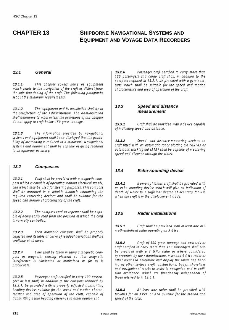
HSC Chapter 13
CHAPTER 13 SHIPBORNE NAVIGATIONAL SYSTEMS AND
EQUIPMENT AND VOYAGE DATA RECORDERS
13.1 General
13.1.1 This chapter covers items of equipmentwhich relate to the navigation of the craft as distinct fromthe safe functioning of the craft. The following paragraphsset out the minimum requirements.
13.1.2 The equipment and its installation shall be tothe satisfaction of the Administration. The Administrationshall determine to what extent the provisions of this chapterdo not apply to craft below 150 gross tonnage.
13.1.3 The information provided by navigationalsystems and equipment shall be so displayed that the proba-bility of misreading is reduced to a minimum. Navigationalsystems and equipment shall be capable of giving readingsto an optimum accuracy.
13.2 Compasses
13.2.1 Craft shall be provided with a magnetic com-pass which is capable of operating without electrical supply,and which may be used for steering purposes. This compassshall be mounted in a suitable binnacle containing therequired correcting devices and shall be suitable for thespeed and motion characteristics of the craft.
13.2.2 The compass card or repeater shall be capa-ble of being easily read from the position at which the craftis normally controlled.
13.2.3 Each magnetic compass shall be properlyadjusted and its table or curve of residual deviations shall beavailable at all times.
13.2.4 Care shall be taken in siting a magnetic com-pass or magnetic sensing element so that magneticinterference is eliminated or minimized as far as ispracticable.
13.2.5 Passenger craft certified to carry 100 passen-gers or less shall, in addition to the compass required by13.2.1, be provided with a properly adjusted transmittingheading device, suitable for the speed and motion charac-teristics and area of operation of the craft, capable oftransmitting a true heading reference to other equipment.
13.2.6 Passenger craft certified to carry more than100 passengers and cargo craft shall, in addition to thecompass required in 13.2.1, be provided with a gyro-com-pass which shall be suitable for the speed and motioncharacteristics and area of operation of the craft.
13.3 Speed and distancemeasurement
13.3.1 Craft shall be provided with a device capableof indicating speed and distance.
13.3.2 Speed- and distance-measuring devices oncraft fitted with an automatic radar plotting aid (ARPA) orautomatic tracking aid (ATA) shall be capable of measuringspeed and distance through the water.
13.4 Echo-sounding device
13.4.1 Non-amphibious craft shall be provided withan echo-sounding device which will give an indication ofdepth of water to a sufficient degree of accuracy for usewhen the craft is in the displacement mode.
13.5 Radar installations
13.5.1 Craft shall be provided with at least one azi-muth-stabilized radar operating on 9 GHz.
13.5.2 Craft of 500 gross tonnage and upwards orcraft certified to carry more than 450 passengers shall alsobe provided with a 3 GHz radar or where consideredappropriate by the Administration, a second 9 GHz radar orother means to determine and display the range and bear-ing of other surface craft, obstructions, buoys, shorelinesand navigational marks to assist in navigation and in colli-sion avoidance, which are functionally independent ofthose referred to in 13.5.1.
13.5.3 At least one radar shall be provided withfacilities for an ARPA or ATA suitable for the motion andspeed of the craft.
218 Bureau Veritas February 2002

HSC Chapter 13
13.5.4 Adequate communication facilities shall beprovided between the radar observer and the person inimmediate charge of the craft.
13.5.5 Each radar installation provided shall be suit-able for the intended craft speed, motion characteristics andcommonly encountered environmental conditions.
13.5.6 Each radar installation shall be mounted soas to be as free as practicable from vibration.
13.6 Electronic positioning systems
Craft shall be provided with a receiver for a global naviga-tion satellite system or a terrestrial radio navigation system,or other means, suitable for use at all times throughout theintended voyage to establish and update the craft's positionby automatic means.
13.7 Rate-of-turn indicator and rudderangle indicator
13.7.1 Craft of 500 gross tonnage or upwards shallbe provided with a rate-of-turn indicator. A rate-of-turn indi-cator shall be provided in craft of less than 500 grosstonnage if the test according to annex 9 shows that the turnrate can exceed safety level 1.
13.7.2 Craft shall be provided with an indicatorshowing the rudder angle. In craft without a rudder, theindicator shall show the direction of steering thrust.
13.8 Nautical charts and nauticalpublications
13.8.1 Craft shall be provided with nautical chartsand nautical publications to plan and display the ship'sroute for the intended voyage and to plot and monitor posi-tions throughout the voyage; an electronic chart display andinformation system (ECDIS) may be accepted as meetingthe chart carriage requirements of this paragraph.
13.8.2 Back-up arrangements shall be provided tomeet the functional requirements of 13.8.1, if this functionis partly or fully fulfilled by electronic means.
13.9 Searchlight and daylightsignalling lamp
13.9.1 Craft shall be provided with at least one ade-quate searchlight, which shall be controllable from theoperating station.
13.9.2 One portable daylight signalling lamp shallbe provided and maintained ready for use in the operatingcompartment at all times.
13.10 Night vision equipment
13.10.1 When operational conditions justify the pro-vision of night vision equipment, such equipment shall beprovided.
13.11 Steering arrangement andpropulsion indicator(s)
13.11.1 The steering arrangement shall be sodesigned that the craft turns in the same direction as that ofthe wheel, tiller, joystick or control lever.
13.11.2 Craft shall be provided with means to showthe mode of the propulsion system(s).
13.11.3 Craft with emergency steering positions shallbe provided with arrangements for supplying visual com-pass readings to the emergency steering position.
13.12 Automatic steering aid(automatic pilot)
13.12.1 Craft shall be provided with an automaticsteering aid (automatic pilot).
13.12.2 Provision shall be made to change from theautomatic to manual mode by a manual override.
13.13 Radar reflector
If practicable, craft of 150 gross tonnage or below shall beprovided with a radar reflector, or other means, to assistdetection by ships navigating by radar at both 9 and 3 GHz.
February 2002 Bureau Veritas 219
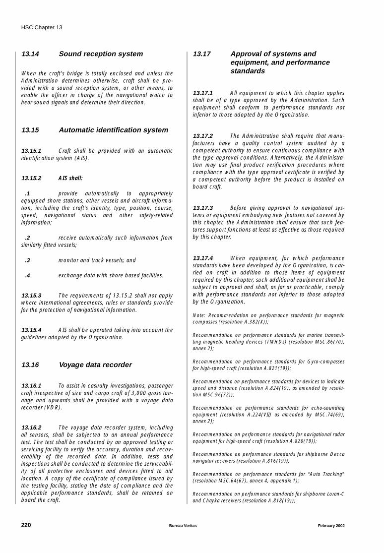
HSC Chapter 13
13.14 Sound reception system
When the craft's bridge is totally enclosed and unless theAdministration determines otherwise, craft shall be pro-vided with a sound reception system, or other means, toenable the officer in charge of the navigational watch tohear sound signals and determine their direction.
13.15 Automatic identification system
13.15.1 Craft shall be provided with an automaticidentification system (AIS).
13.15.2 AIS shall:
.1 provide automatically to appropriatelyequipped shore stations, other vessels and aircraft informa-tion, including the craft's identity, type, position, course,speed, navigational status and other safety-relatedinformation;
.2 receive automatically such information fromsimilarly fitted vessels;
.3 monitor and track vessels; and
.4 exchange data with shore based facilities.
13.15.3 The requirements of 13.15.2 shall not applywhere international agreements, rules or standards providefor the protection of navigational information.
13.15.4 AIS shall be operated taking into account theguidelines adopted by the Organization.
13.16 Voyage data recorder
13.16.1 To assist in casualty investigations, passengercraft irrespective of size and cargo craft of 3,000 gross ton-nage and upwards shall be provided with a voyage datarecorder (VDR).
13.16.2 The voyage data recorder system, includingall sensors, shall be subjected to an annual performancetest. The test shall be conducted by an approved testing orservicing facility to verify the accuracy, duration and recov-erability of the recorded data. In addition, tests andinspections shall be conducted to determine the serviceabil-ity of all protective enclosures and devices fitted to aidlocation. A copy of the certificate of compliance issued bythe testing facility, stating the date of compliance and theapplicable performance standards, shall be retained onboard the craft.
13.17 Approval of systems andequipment, and performancestandards
13.17.1 All equipment to which this chapter appliesshall be of a type approved by the Administration. Suchequipment shall conform to performance standards notinferior to those adopted by the Organization.
13.17.2 The Administration shall require that manu-facturers have a quality control system audited by acompetent authority to ensure continuous compliance withthe type approval conditions. Alternatively, the Administra-tion may use final product verification procedures wherecompliance with the type approval certificate is verified bya competent authority before the product is installed onboard craft.
13.17.3 Before giving approval to navigational sys-tems or equipment embodying new features not covered bythis chapter, the Administration shall ensure that such fea-tures support functions at least as effective as those requiredby this chapter.
13.17.4 When equipment, for which performancestandards have been developed by the Organization, is car-ried on craft in addition to those items of equipmentrequired by this chapter, such additional equipment shall besubject to approval and shall, as far as practicable, complywith performance standards not inferior to those adoptedby the Organization.
Note: Recommendation on performance standards for magneticcompasses (resolution A.382(X));
Recommendation on performance standards for marine transmit-ting magnetic heading devices (TMHDs) (resolution MSC.86(70),annex 2);
Recommendation on performance standards for Gyro-compassesfor high-speed craft (resolution A.821(19));
Recommendation on performance standards for devices to indicatespeed and distance (resolution A.824(19), as amended by resolu-tion MSC.96(72));
Recommendation on performance standards for echo-soundingequipment (resolution A.224(VII) as amended by MSC.74(69),annex 2);
Recommendation on performance standards for navigational radarequipment for high-speed craft (resolution A.820(19));
Recommendation on performance standards for shipborne Deccanavigator receivers (resolution A.816(19));
Recommendation on performance standards for “Auto Tracking”(resolution MSC.64(67), annex 4, appendix 1);
Recommendation on performance standards for shipborne Loran-Cand Chayka receivers (resolution A.818(19));
220 Bureau Veritas February 2002
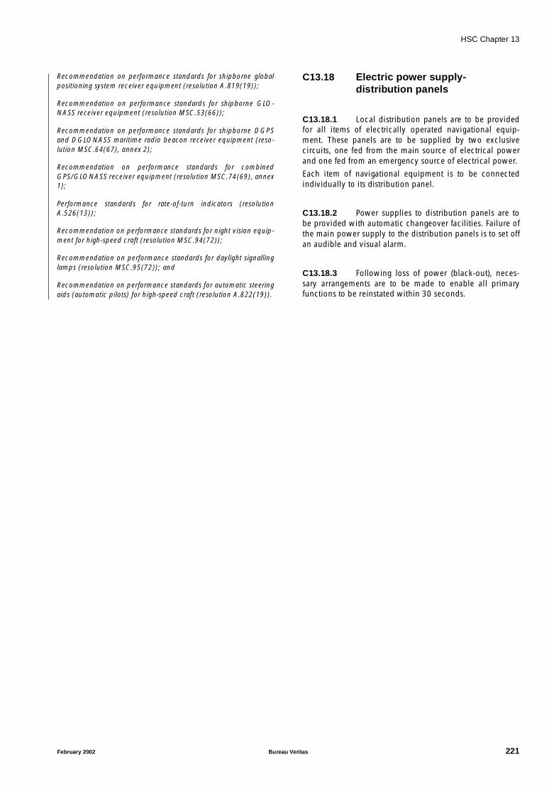
HSC Chapter 13
Recommendation on performance standards for shipborne globalpositioning system receiver equipment (resolution A.819(19));
Recommendation on performance standards for shipborne GLO-NASS receiver equipment (resolution MSC.53(66));
Recommendation on performance standards for shipborne DGPSand DGLONASS maritime radio beacon receiver equipment (reso-lution MSC.64(67), annex 2);
Recommendation on performance standards for combinedGPS/GLONASS receiver equipment (resolution MSC.74(69), annex1);
Performance standards for rate-of-turn indicators (resolutionA.526(13));
Recommendation on performance standards for night vision equip-ment for high-speed craft (resolution MSC.94(72));
Recommendation on performance standards for daylight signallinglamps (resolution MSC.95(72)); and
Recommendation on performance standards for automatic steeringaids (automatic pilots) for high-speed craft (resolution A.822(19)).
C13.18 Electric power supply-distribution panels
C13.18.1 Local distribution panels are to be providedfor all items of electrically operated navigational equip-ment. These panels are to be supplied by two exclusivecircuits, one fed from the main source of electrical powerand one fed from an emergency source of electrical power.
Each item of navigational equipment is to be connectedindividually to its distribution panel.
C13.18.2 Power supplies to distribution panels are tobe provided with automatic changeover facilities. Failure ofthe main power supply to the distribution panels is to set offan audible and visual alarm.
C13.18.3 Following loss of power (black-out), neces-sary arrangements are to be made to enable all primaryfunctions to be reinstated within 30 seconds.
February 2002 Bureau Veritas 221
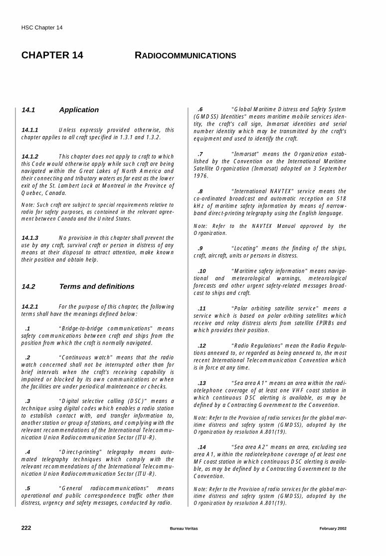
HSC Chapter 14
CHAPTER 14 RADIOCOMMUNICATIONS
14.1 Application
14.1.1 Unless expressly provided otherwise, thischapter applies to all craft specified in 1.3.1 and 1.3.2.
14.1.2 This chapter does not apply to craft to whichthis Code would otherwise apply while such craft are beingnavigated within the Great Lakes of North America andtheir connecting and tributary waters as far east as the lowerexit of the St. Lambert Lock at Montreal in the Province ofQuebec, Canada.
Note: Such craft are subject to special requirements relative toradio for safety purposes, as contained in the relevant agree-ment between Canada and the United States.
14.1.3 No provision in this chapter shall prevent theuse by any craft, survival craft or person in distress of anymeans at their disposal to attract attention, make knowntheir position and obtain help.
14.2 Terms and definitions
14.2.1 For the purpose of this chapter, the followingterms shall have the meanings defined below:
.1 “Bridge-to-bridge communications” meanssafety communications between craft and ships from theposition from which the craft is normally navigated.
.2 “Continuous watch” means that the radiowatch concerned shall not be interrupted other than forbrief intervals when the craft's receiving capability isimpaired or blocked by its own communications or whenthe facilities are under periodical maintenance or checks.
.3 “Digital selective calling (DSC)” means atechnique using digital codes which enables a radio stationto establish contact with, and transfer information to,another station or group of stations, and complying with therelevant recommendations of the International Telecommu-nication Union Radiocommunication Sector (ITU-R).
.4 “Direct-printing” telegraphy means auto-mated telegraphy techniques which comply with therelevant recommendations of the International Telecommu-nication Union Radiocommunication Sector (ITU-R).
.5 “General radiocommunications” meansoperational and public correspondence traffic other thandistress, urgency and safety messages, conducted by radio.
.6 “Global Maritime Distress and Safety System(GMDSS) Identities” means maritime mobile services iden-tity, the craft's call sign, Inmarsat identities and serialnumber identity which may be transmitted by the craft'sequipment and used to identify the craft.
.7 “Inmarsat” means the Organization estab-lished by the Convention on the International MaritimeSatellite Organization (Inmarsat) adopted on 3 September1976.
.8 “International NAVTEX” service means theco-ordinated broadcast and automatic reception on 518kHz of maritime safety information by means of narrow-band direct-printing telegraphy using the English language.
Note: Refer to the NAVTEX Manual approved by theOrganization.
.9 “Locating” means the finding of the ships,craft, aircraft, units or persons in distress.
.10 “Maritime safety information” means naviga-tional and meteorological warnings, meteorologicalforecasts and other urgent safety-related messages broad-cast to ships and craft.
.11 “Polar orbiting satellite service” means aservice which is based on polar orbiting satellites whichreceive and relay distress alerts from satellite EPIRBs andwhich provides their position.
.12 “Radio Regulations” mean the Radio Regula-tions annexed to, or regarded as being annexed to, the mostrecent International Telecommunication Convention whichis in force at any time.
.13 “Sea area A1” means an area within the radi-otelephone coverage of at least one VHF coast station inwhich continuous DSC alerting is available, as may bedefined by a Contracting Government to the Convention.
Note: Refer to the Provision of radio services for the global mar-itime distress and safety system (GMDSS), adopted by theOrganization by resolution A.801(19).
.14 “Sea area A2” means an area, excluding seaarea A1, within the radiotelephone coverage of at least oneMF coast station in which continuous DSC alerting is availa-ble, as may be defined by a Contracting Government to theConvention.
Note: Refer to the Provision of radio services for the global mar-itime distress and safety system (GMDSS), adopted by theOrganization by resolution A.801(19).
222 Bureau Veritas February 2002

HSC Chapter 14
.15 “Sea area A3” means an area, excluding seaareas A1 and A2, within the coverage of an Inmarsat geosta-tionary satellite in which continuous alerting is available.
.16 “Sea area A4” means an area outside seaareas A1, A2 and A3.
14.2.2 All other terms and abbreviations which areused in this chapter and which are defined in the RadioRegulations and in the International Convention on Mari-time Search and Rescue (SAR), 1979, as it may beamended, shall have the meanings as defined in those Regu-lations and the SAR Convention.
14.3 Exemptions
14.3.1 It is considered highly desirable not to devi-ate from the requirements of this chapter; nevertheless theAdministration, in conjunction with the base port State, maygrant partial or conditional exemptions to individual craftfrom the requirements of 14.7 to 14.11 provided:
.1 such craft comply with the functionalrequirements of 14.5; and
.2 the Administration has taken into accountthe effect such exemptions may have upon the general effi-ciency of the service for the safety of all ships and craft.
14.3.2 An exemption may be granted under 14.3.1only:
.1 if the conditions affecting safety are such asto render the full application of 14.7 to 14.11 unreasonableor unnecessary; or
.2 in exceptional circumstances, for a singlevoyage outside the sea area or sea areas for which the craftis equipped.
14.3.3 Each Administration shall submit to theOrganization, as soon as possible after the first of January ineach year, a report showing all exemptions granted under14.3.1 and 14.3.2 during the previous calendar year andgiving the reasons for granting such exemptions.
14.4 Global maritime distress andsafety system identities
14.4.1 This section applies to all craft on all voyages.
14.4.2 Each Administration undertakes to ensurethat suitable arrangements are made for registering GlobalMaritime Distress and Safety System (GMDSS) Identitiesand for making information on these identities available toRescue Co-ordination Centres on a 24-hour basis. Where
appropriate, international organizations maintaining a regis-try of these identities shall be notified by the Administrationof these assignments.
14.5 Functional requirements
14.5.1 Every craft, while at sea, shall be capable:
.1 except as provided in 14.8.1.1 and14.10.1.4.3, of transmitting ship-to-shore distress alerts byat least two separate and independent means, each using adifferent radiocommunication service;
.2 of receiving shore-to-ship distress alerts;
.3 of transmitting and receiving ship-to-ship dis-tress alerts;
.4 of transmitting and receiving search and res-cue co-ordinating communications;
.5 of transmitting and receiving on-scenecommunications;
.6 of transmitting and, as required by 13.5,receiving signals for locating,
Note: Refer to Carriage of radar operating in the frequencyband 9,300–9,500 MHz, adopted by the Organization by seeresolution A.614(15).
.7 of transmitting and receiving maritime safetyinformation;
Note: It should be noted that craft may have a need for recep-tion of certain maritime safety information while in port.
.8 of transmitting and receiving general radio-communications to and from shore-based radio systems ornetworks subject to 14.15.8; and
.9 of transmitting and receiving bridge-to-bridgecommunications.
14.6 Radio installations
14.6.1 Every craft shall be provided with radioinstallations capable of complying with the functionalrequirements prescribed by 14.5 throughout its intendedvoyage and, unless exempted under 14.3, complying withthe requirements of 14.7 and, as appropriate for the seaarea or areas through which it will pass during its intendedvoyage, the requirements of either 14.8, 14.9, 14.10 or14.11.
14.6.2 Every radio installation shall:
.1 be so located that no harmful interference ofmechanical, electrical or other origin affects its proper use,
February 2002 Bureau Veritas 223
HSC Chapter 14
and so as to ensure electromagnetic compatibility andavoidance of harmful interaction with other equipment andsystems;
.2 be so located as to ensure the greatest possi-ble degree of safety and operational availability;
.3 be protected against harmful effects of water,extremes of temperature and other adverse environmentalconditions;
.4 be provided with reliable, permanentlyarranged electrical lighting, independent of the mainsources of electrical power, for the adequate illumination ofthe radio controls for operating the radio installation; and
.5 be clearly marked with the call sign, the shipstation identity and other codes as applicable for the use ofthe radio installation.
14.6.3 Control of the VHF radiotelephone channels,required for navigational safety, shall be immediately availa-ble on the navigating bridge convenient to the conningposition, and, where necessary, facilities shall be availableto permit radiocommunications from the wings of the navi-gating bridge. Portable VHF equipment may be used tomeet the latter provision.
14.6.4 In passenger craft, a distress panel shall beinstalled at the conning position. This panel shall containeither one single button which, when pressed, initiates adistress alert using all radiocommunication installationsrequired on board for that purpose or one button for eachindividual installation. The panel shall clearly and visuallyindicate whenever any button or buttons have beenpressed. Means shall be provided to prevent inadvertentactivation of the button or buttons. If the satellite EPIRB isused as the secondary means of distress alerting and is notremotely activated, it shall be acceptable to have an addi-tional EPIRB installed in the wheelhouse near the conningposition.
14.6.5 In passenger craft, information on the craft'sposition shall be continuously and automatically providedto all relevant radiocommunication equipment to beincluded in the initial distress alert when the button or but-tons on the distress panel is pressed.
14.6.6 In passenger craft, a distress alert panel shallbe installed at the conning position. The distress alarmpanel shall provide visual and aural indication of any dis-tress alert or alerts received on board and shall also indicatethrough which radiocommunication service the distressalerts have been received.
14.7 Radio equipment: general
14.7.1 Every craft shall be provided with:
.1 a VHF radio installation capable of transmit-ting and receiving:
.1.1 DSC on the frequency 156.525 MHz (channel70). It shall be possible to initiate the transmis-sion of distress alerts on channel 70 from theposition from which the craft is normally navi-gated; and
.1.2 radiotelephony on the frequencies 156.300MHz (channel 6), 156.650 MHz (channel 13)and 156.800 MHz (channel 16);
.2 a radio installation capable of maintaining acontinuous DSC watch on VHF channel 70 which may beseparate from, or combined with, that required by14.7.1.1.1;
.3 a radar transponder capable of operating inthe 9 GHz band, which:
.3.1 shall be so stowed that it can be easily utilized;and
.3.2 may be one of those required by 8.2.1.2 for asurvival craft;
.4 a receiver capable of receiving InternationalNAVTEX service broadcasts if the craft is engaged on voy-ages in any area in which an International NAVTEX serviceis provided;
.5 a radio facility for reception (see note 1) ofmaritime safety information by the Inmarsat enhancedgroup calling system if the craft is engaged on voyages inany area of Inmarsat coverage but in which an InternationalNAVTEX service is not provided. However, craft engagedexclusively on voyages in areas where a HF direct printingtelegraphy maritime safety information service is providedand fitted with equipment capable of receiving such servicemay be exempt from this requirements (see note 2).
Note 1 : Refer to Carriage of Inmarsat enhanced group callSafetyNET receivers under the GMDSS, adopted by the Organ-ization by resolution A.701(17).
Note 2 : Refer to the Recommendation on Promulgation ofMaritime Safety Information, adopted by the Organization byresolution A.705(17).
.6 subject to the provisions of 14.8.3, a satelliteemergency position indicating radio beacon (satelliteEPIRB) which shall be:
Note: Refer to Search and rescue homing capability, adoptedby the Organization by resolution A.616(15).
.6.1 capable of transmitting a distress alert eitherthrough the polar orbiting satellite service oper-ating in the 406 MHz band or, if the craft isengaged only on voyages within Inmarsat cover-age, through the Inmarsat geostationary satelliteservice operating in the 1.6 GHz band;
.6.2 installed in an easily accessible position;
224 Bureau Veritas February 2002

HSC Chapter 14
.6.3 ready to be manually released and capable ofbeing carried by one person into a survivalcraft;
.6.4 capable of floating free if the craft sinks and ofbeing automatically activated when afloat; and
.6.5 capable of being activated manually.
14.7.2 Every passenger craft shall be provided withmeans for two-way on-scene radiocommunications forsearch and rescue purposes using the aeronautical frequen-cies 121.5 MHz and 123.1 MHz from the position fromwhich the craft is normally navigated.
14.8 Radio equipment: sea area A1
14.8.1 In addition to meeting the requirements of14.7, every craft engaged on voyages exclusively in sea areaA1 shall be provided with a radio installation capable of ini-tiating the transmission of ship-to-shore distress alerts fromthe position from which the craft is normally navigated,operating either:
.1 on VHF using DSC; this requirement may befulfilled by the EPIRB prescribed by 14.8.3, either by install-ing the EPIRB close to, or by remote activation from, theposition from which the craft is normally navigated; or
.2 through the polar orbiting satellite service on406 MHz; this requirement may be fulfilled by the satelliteEPIRB, required by 14.7.1.6, either by installing the satelliteEPIRB close to, or by remote activation from, the positionfrom which the craft is normally navigated; or
.3 if the craft is on voyages within coverage ofMF coast stations equipped with DSC on MF using DSC; or
.4 on HF using DSC; or
.5 through the Inmarsat geostationary satelliteservice; this requirement may be fulfilled by:
.5.1 an Inmarsat ship earth station (see note); or
.5.2 the satellite EPIRB, required by 14.7.1.6, eitherby installing the satellite EPIRB close to, or byremote activation from, the position from whichthe craft is normally navigated.
Note: This requirement can be met by Inmarsat ship earth sta-tions capable of two-way communications, such as Inmarsat-Aand -B (resolution A.808(19)) or Inmarsat-C (resolutionA.807(19) and MSC.68(68), annex 4) ship earth stations.Unless otherwise specified, this footnote applies to all require-ments for an Inmarsat ship earth station prescribed by thischapter.
14.8.2 The VHF radio installation, required by14.71.1, shall also be capable of transmitting and receivinggeneral radiocommunications using radiotelephony.
14.8.3 Craft engaged on voyages exclusively in seaarea A1 may carry, in lieu of the satellite EPIRB required by14.7.1.6, an EPIRB which shall be:
.1 capable of transmitting a distress alert usingDSC on VHF channel 70 and providing for locating bymeans of a radar transponder operating in the 9 GHz band;
.2 installed in an easily accessible position;
.3 ready to be manually released and capableof being carried by one person into a survival craft;
.4 capable of floating free if the craft sinks andof being automatically activated when afloat; and
.5 capable of being activated manually.
14.9 Radio equipment: sea areas A1and A2
14.9.1 In addition to meeting the requirements of14.7, every craft engaged on voyages beyond sea area A1,but remaining within sea area A2, shall be provided with:
.1 an MF radio installation capable of transmit-ting and receiving, for distress and safety purposes, on thefrequencies:
.1.1 2,187.5 kHz using DSC; and
.1.2 2,182 kHz using radiotelephony;
.2 a radio installation capable of maintaining acontinuous DSC watch on the frequency 2,187.5 kHzwhich may be separate from, or combined with, thatrequired by 14.9.1.1.1; and
.3 means of initiating the transmission of ship-to-shore distress alerts by a radio service other than MF,operating either:
.3.1 through the polar orbiting satellite service on406 MHz; this requirement may be fulfilled bythe satellite EPIRB, required by 14.7.1.6, eitherby installing the satellite EPIRB close to, or byremote activation from, the position from whichthe craft is normally navigated; or
.3.2 on HF using DSC; or
.3.3 through the Inmarsat geostationary satelliteservice; this requirement may be fulfilled by:
.3.3.1 the equipment specified in 14.9.3.2; or
February 2002 Bureau Veritas 225
HSC Chapter 14
.3.3.2 the satellite EPIRB, required by 14.7.1.6, eitherby installing the satellite EPIRB close to, or byremote activation from, the position from whichthe craft is normally navigated.
14.9.2 It shall be possible to initiate transmission ofdistress alerts by the radio installations specified in 14.9.1.1and 14.9.1.3 from the position from which the craft is nor-mally navigated.
14.9.3 The craft shall, in addition, be capable oftransmitting and receiving general radiocommunicationsusing radiotelephony or direct-printing telegraphy by either:
.1 a radio installation operating on working fre-quencies in the bands between 1,605 kHz and 4,000 kHzor between 4,000 kHz and 27,500 kHz; this requirementmay be fulfilled by the addition of this capability in theequipment required by 14.9.1.1; or
.2 an Inmarsat ship earth station.
14.10 Radio equipment: sea areas A1,A2 and A3
14.10.1 In addition to meeting the requirements of14.7, every craft engaged on voyages beyond sea areas A1and A2, but remaining within sea area A3, shall, if it doesnot comply with the requirements of 14.10.2, be providedwith:
.1 an Inmarsat ship earth station capable of:
.1.1 transmitting and receiving distress and safetycommunications using direct-printingtelegraphy;
.1.2 initiating and receiving distress priority calls;
.1.3 maintaining watch for shore-to-ship distressalerts, including those directed to specificallydefined geographical areas; and
.1.4 transmitting and receiving general radiocommu-nications, using either radiotelephony or direct-printing telegraphy;
.2 an MF radio installation capable of transmit-ting and receiving, for distress and safety purposes, on thefrequencies:
.2.1 2,187.5 kHz using DSC; and
.2.2 2,182 kHz using radiotelephony;
.3 a radio installation capable of maintaining acontinuous DSC watch on the frequency 2,187.5 kHzwhich may be separate from, or combined with, thatrequired by 14.10.1.2.1; and
.4 means of initiating the transmission of ship-to-shore distress alerts by a radio service operating either:
.4.1 through the polar orbiting service on 406 MHz;this requirement may be fulfilled by the satelliteEPIRB, required by 14.7.1.6, either by installingthe satellite EPIRB close to, or by remote activa-tion from, the position from which the craft isnormally navigated; or
.4.2 on HF using DSC; or
.4.3 through the Inmarsat geostationary satelliteservice, by an additional ship earth station or bythe satellite EPIRB required by 14.7.1.6, eitherby installing the satellite EPIRB close to, or byremote activation from, the position from whichthe craft is normally navigated.
14.10.2 In addition to meeting the requirements of14.7, every craft engaged on voyages beyond sea areas A1and A2, but remaining within sea area A3, shall, if it doesnot comply with the requirements of 14.10.1, be providedwith:
.1 an MF/HF radio installation capable of trans-mitting and receiving, for distress and safety purposes, onall distress and safety frequencies in the bands between1,605 kHz and 4,000 kHz and between 4,000 kHz and27,500 kHz:
.1.1 using DSC;
.1.2 using radiotelephony; and
.1.3 using direct-printing telegraphy;
.2 equipment capable of maintaining a DSCwatch on 2,187.5 kHz, 8,414.5 kHz and on at least one ofthe distress and safety DSC frequencies 4,207.5 kHz, 6,312kHz, 12,577 kHz or 1 6,804.5 kHz at any time, it shall bepossible to select any of these DSC distress and safety fre-quencies. This equipment may be separate from, orcombined with, the equipment required by 14.10.2.1;
.3 means of initiating the transmission of ship-to-shore distress alerts by a radiocommunication serviceother than HF operating either:
.3.1 through the polar orbiting satellite service on406 MHz; this requirement may be fulfilled bythe satellite EPIRB required by 14.7.1.6, eitherby installing the satellite EPIRB close to, or byremote activation from, the position from whichthe craft is normally navigated; or
.3.2 through the Inmarsat geostationary satelliteservice, this requirement may be fulfilled by:
.3.2.1 an Inmarsat ship earth station; or
226 Bureau Veritas February 2002

HSC Chapter 14
.3.2.2 the satellite EPIRB, required by 14.7.1.6, eitherby installing the satellite EPIRB close to, or byremote activation from, the position from whichthe craft is normally navigated; and
.4 in addition, the craft shall be capable oftransmitting and receiving general radiocommunicationsusing radiotelephony or direct-printing telegraphy by anMF/HF radio installation operating on working frequenciesin the bands between 1,605 kHz and 4,000 kHz andbetween 4,000 kHz and 27,500 kHz. This requirement maybe fulfilled by the addition of this capability in the equip-ment required by 14.10.2.1.
14.10.3 It shall be possible to initiate transmission ofdistress alerts by the radio installations specified in14.10.1.1, 14.10.1.2, 14.10.1.4, 14.10.2.1 and 14.10.2.3from the position from which the craft is normallynavigated.
14.11 Radio equipment: sea areas A1,A2, A3 and A4
14.11.1 In addition to meeting the requirements of14.7, craft engaged on voyages in all sea areas shall be pro-vided with the radio installations and equipment requiredby 14.10.2, except that the equipment required by14.10.2.3.2 shall not be accepted as an alternative to thatrequired by 14.10.2.3.1, which shall always be provided. Inaddition, craft engaged on voyages in all sea areas shallcomply with the requirements of 14.10.3.
14.12 Watches
14.12.1 Every craft, while at sea, shall maintain acontinuous watch:
.1 on VHF DSC channel 70, if the craft, inaccordance with the requirements of 14.7.1.2, is fitted witha VHF radio installation;
.2 on the distress and safety DSC frequency2,187.5 kHz, if the craft, in accordance with the require-ments of 14.9.1.2 or 14.10.1.3, is fitted with an MF radioinstallation;
.3 on the distress and safety DSC frequencies2,187.5 kHz and 8,414.5 kHz and also on at least one ofthe distress and safety DSC frequencies 4,207.5 kHz, 6,312kHz, 12,577 kHz or 16,804.5 kHz, appropriate to the timeof day and the geographical position of the craft, if the craft,in accordance with the requirements of 14.10.2.2 or14.11.1, is fitted with an MF/HF radio installation. Thiswatch may be kept by means of a scanning receiver; and
.4 for satellite shore-to-ship distress alerts, if thecraft, in accordance with the requirements of 14.10.1.1, isfitted with an Inmarsat ship earth station.
14.12.2 Every craft, while at sea, shall maintain aradio watch for broadcasts of maritime safety informationon the appropriate frequency or frequencies on which suchinformation is broadcast for the area in which the craft isnavigating.
14.12.3 Until 1 February 2005, every craft, while atsea shall continue to maintain, when practicable, a continu-ous listening watch on VHF channel 16. This watch shall bekept at the position from which the craft is normallynavigated.
14.13 Sources of energy
14.13.1 There shall be available at all times, while thecraft is at sea, a supply of electrical energy sufficient tooperate the radio installations and to charge any batteriesused as part of a reserve source of energy for the radioinstallations.
14.13.2 Reserve and emergency sources of energyshall be provided on every craft to supply radio installa-tions, for the purpose of conducting distress and safetyradiocommunications, in the event of failure of the craft'smain and emergency sources of electrical power. Thereserve source of energy shall be capable of simultaneouslyoperating the VHF radio installation required by 14.7.1.1and, as appropriate for the sea area or sea areas for whichthe craft is equipped, either the MF radio installationrequired by 14.9.1.1, the MF/HF radio installation requiredby 14.10.2.1 or 14.11.1 or the Inmarsat ship earth stationrequired by 14.10.1.1 and any of the additional loads men-tioned in 14.13.5 and 14.13.8 for a period of at least 1 h.
14.13.3 The reserve source of energy shall be inde-pendent of the propelling power of the craft and the craft'selectrical system.
14.13.4 Where, in addition to the VHF radio installa-tion, two or more of the other radio installations referred toin 14.13.2 can be connected to the reserve source orsources of energy, they shall be capable of simultaneouslysupplying, for the period specified in 14.13.2, the VHFradio installation and:
.1 all other radio installations which can beconnected to the reserve source of energy at the same time;or
.2 whichever of the radio installations will con-sume the most power, if only one of the other radioinstallations can be connected to the reserve source ofenergy at the same time as the VHF radio installation.
February 2002 Bureau Veritas 227
HSC Chapter 14
14.13.5 The reserve source of energy may be used tosupply the electrical lighting required by 14.6.2.4.
14.13.6 Where a reserve source of energy consists ofa rechargeable accumulator battery or batteries:
.1 a means of automatically charging such bat-teries shall be provided which shall be capable ofrecharging them to minimum capacity requirements within10 h; and
.2 the capacity of the battery or batteries shallbe checked, using an appropriate method at intervals notexceeding 12 months, when the craft is not at sea.
Note: One method of checking the capacity of an accumulatorbattery is to fully discharge and recharge the battery, using nor-mal operating current and period (e.g. 10 h). Assessment of thecharge condition can be made at any time, but it should bedone without significant discharge of the battery when the craftis at sea.
14.13.7 The siting and installation of accumulatorbatteries which provide a reserve source of energy shall besuch as to ensure:
.1 the highest degree of service;
.2 a reasonable lifetime;
.3 reasonable safety;
.4 that the battery temperatures remain withinthe manufacturer's specifications whether under charge oridle; and
.5 that when fully charged, the batteries willprovide at least the minimum required hours of operationunder all weather conditions.
14.13.8 If an uninterrupted input of information fromthe craft's navigational or other equipment to a radio instal-lation required by this chapter is needed to ensure itsproper performance, including the navigation receiverreferred to in 14.18, means shall be provided to ensure thecontinuous supply of such information in the event of failureof the craft's main or emergency source of electrical power.
14.14 Performance standards
14.14.1 All equipment to which this chapter appliesshall be of a type approved by the Administration. Suchequipment shall conform to appropriate performance stand-ards not inferior to those adopted by the Organization.
Note: Refer to the following resolutions adopted by the Organiza-tion:
(1) Resolution A.525(13): Performance Standards for Narrow-Band Direct-Printing Telegraph Equipment for the Recep-tion of Navigational and Meteorological Warnings andUrgent Information to Ships.
(2) Resolution A.694(17): General Requirements for ShipborneRadio Equipment Forming Part of the Global Maritime Dis-tress and Safety System (GMDSS) and for ElectronicNavigational Aids.
(3) Resolution A.808(19): Performance Standards for ShipEarth Stations Capable of Two-Way Communications, andresolution A.570(14), Type Approval of Ship Earth Stations.
(4) Resolutions A.803(19): and MSC.68(68), annex 1: Per-formance Standards for Shipborne VHF Radio installationsCapable of Voice Communication and Digital SelectiveCalling.
(5) Resolutions A.804(19) and MSC.68(68), annex 2: Perform-ance Standards for Shipborne MF Radio InstallationsCapable of Voice Communication and Digital SelectiveCalling.
(6) Resolutions A.806(19) and MSC.68(68), annex 3: Perform-ance Standards for Shipborne MF/HF Radio InstallationsCapable of Voice Communication, Narrow-Band DirectPrinting and Digital Selective Calling.
(7) Resolutions A.810(19) and MSC.56(66): PerformanceStandards for Float-Free Satellite Emergency Position-Indi-cating Radio Beacons (EPIRBs) Operating on 406 MHz(see also Assembly resolution A.696(17): Type Approval ofSatellite Emergency Position-Indicating Radio Beacons(EPIRBs) Operating in the COSPAS-SARSAT System).
(8) Resolution A.802(19): Performance Standards for SurvivalCraft Radar Transponders for Use in Search and RescueOperations.
(9) Resolution A.805(19): Performance Standards for Float-Free VHF Emergency Position-Indicating Radio Beacons.
(10)Resolutions A.807(19) and MSC.68(68), annex 4: Per-formance Standards for Inmarsat Standard-C Ship EarthStations Capable of Transmitting and Receiving Direct-Print-ing Communications, and resolution A.570(14), TypeApproval of Ship Earth Stations.
(11)Resolution A.664(16): Performance Standards forEnhanced Group Call Equipment.
(12)Resolution A.812(19): Performance Standards for Float-Free Satellite Emergency Position-indicating Radio BeaconsOperating Through the Geostationary Inmarsat SatelliteSystem on 1.6 GHz.
(13)Resolution A.662(16): Performance Standards for Float-Free Release and Activation Arrangements for EmergencyRadio Equipment.
(14)Resolution A.699(17): System Performance Standard forthe Promulgation and Co-ordination of Maritime SafetyInformation Using High-Frequency Narrow-Band DirectPrinting.
(15)Resolution A.700(17): Performance Standards for Narrow-Band Direct-Printing Telegraph Equipment for the Recep-tion of Navigational and Meteorological Warnings andUrgent Information to Ships (MSI) by HF.
(16)Resolution MSC.80(70): Recommendation on Perform-ance Standards for on-scene (Aeronautical) Portable Two-Way VHF Radiotelephone Apparatus.
228 Bureau Veritas February 2002

HSC Chapter 14
14.15 Maintenance requirements
14.15.1 Equipment shall be so designed that the mainunits can be replaced readily without elaborate recalibra-tion or readjustment.
14.15.2 Where applicable, equipment shall be soconstructed and installed that it is readily accessible forinspection and on-board maintenance purposes.
14.15.3 Adequate information shall be provided toenable the equipment to be properly operated and main-tained, taking into account the recommendations of theOrganization.
Note: Refer to the Recommendation on General Requirementsfor Shipborne Radio Equipment Forming Part of the GlobalMaritime Distress and Safety System (GMDSS) and for Elec-tronic Navigational Aids, adopted by the Organization byresolution A.694(17).
14.15.4 Adequate tools and spares shall be providedto enable equipment to be maintained.
14.15.5 The Administration shall ensure that radioequipment required by this chapter is maintained to providethe availability of the functional requirements specified in14.5 and to meet the recommended performance standardsof such equipment.
14.15.6 On craft engaged on voyages in sea areas A1and A2, the availability shall be ensured by using suchmethods as duplication of equipment, shore-based mainte-nance or at-sea electronic maintenance capability, or acombination of these, as may be approved by theAdministration.
14.15.7 On craft engaged on voyages in sea areas A3and A4, the availability shall be ensured by using a combi-nation of at least two methods, such as duplication ofequipment, shore-based maintenance or at-sea electronicmaintenance capability, as may be approved by the Admin-istration, taking into account the recommendations of theOrganization.
Note: Administrations should take account of the Radio Main-tenance Guidelines for the Global Maritime Distress and SafetySystem (GMDSS) related to Sea Areas A3 and A4, adopted bythe Organization by resolution A.702(17).
14.15.8 However, for craft operating solely betweenports where adequate facilities for shorebased maintenanceof the radio installations are available and provided no jour-ney between two such ports exceeds six hours, then theAdministration may exempt such craft from the requirementto use at least two maintenance methods. For such craft atleast one maintenance method shall be used.
14.15.9 While all reasonable steps shall be taken tomaintain the equipment in efficient working order to ensurecompliance with all the functional requirements specified in14.5, malfunction of the equipment for providing the gen-eral radiocommunications, required by 14.8, shall not beconsidered as making a craft unseaworthy or as a reason fordelaying the craft in ports where repair facilities are notreadily available, provided the craft is capable of performingall distress and safety functions.
14.15.10 Satellite EPIRBs shall be tested at intervalsnot exceeding 12 months for all aspects of operational effi-ciency with particular emphasis on frequency stability,signal strength and coding. However, in cases where itappears proper and reasonable, the Administration mayextend this period to 17 months. The test may be con-ducted on board the ship or at an approved testing orservicing station.
14.16 Radio personnel
14.16.1 Every craft shall carry personnel qualified fordistress and safety radiocommunication purposes to the sat-isfaction of the Administration. The personnel shall beholders of certificates specified in the Radio Regulations asappropriate, any one of whom shall be designated to haveprimary responsibility for radiocommunications during dis-tress incidents.
14.16.2 In passenger craft, at least one person quali-fied in accordance with sub-paragraph .1 shall be assignedto perform only radiocommunication duties during distressincidents.
14.17 Radio records
A record shall be kept, to the satisfaction of the Administra-tion and as required by the Radio Regulations, of allincidents connected with the radiocommunication servicewhich appear to be of importance to safety of life at sea.
14.18 Position-updating
All two-way communication equipment carried on boardcraft to which this chapter applies which is capable of auto-matically including the craft's position in the distress alertshall be automatically provided with this information froman internal or external navigation receiver, if either isinstalled. If such a receiver is not installed, the craft's posi-tion and the time that position was correct shall bemanually updated at intervals not exceeding four hours,while the craft is underway, so that it is always ready fortransmission by the equipment.
February 2002 Bureau Veritas 229
HSC Chapter 15
CHAPTER 15 OPERATING COMPARTMENT LAYOUT
15.1 Definitions
15.1.1 “Operating area” is the operating compart-ment and those parts of the craft on both sides of, and closeto, the operating compartment which extend to the craft'sside.
15.1.2 “Workstation” is a position at which one orseveral tasks constituting a particular activity are carriedout.
15.1.3 “Docking workstation” is a place equippedwith necessary means for docking the craft.
15.1.4 “Primary controls” are all control equipmentnecessary for the safe operation of the craft when it is underway, including those required in an emergency situation.
15.2 General
The design and layout of the compartment from which thecrew operate the craft shall be such as to permit operatingcrew members to perform their duties in a correct mannerwithout unreasonable difficulty, fatigue or concentration,and to minimize the likelihood of injury to operating crewmembers in both normal and emergency conditions.
15.3 Field of vision from the operatingcompartment
15.3.1 The operating station shall be placed aboveall other superstructures so that the operating crew are ableto gain a view all round the horizon from the navigatingworkstation. Where it is impractical to meet the require-ments of this paragraph from a single navigatingworkstation, the operating station shall be designed so thatan all-round view of the horizon is obtained by using twonavigating workstations combined or by any other means tothe satisfaction of the Administration.
15.3.2 Blind sectors shall be as few and as small aspossible, and not adversely affect the keeping of a safe look-out from the operating station. If stiffeners between win-dows are to be covered, this shall not cause furtherobstruction inside the wheelhouse.
15.3.3 The total arc of blind sectors from rightahead to 22.5° abaft the beam on either side shall notexceed 20°. Each individual blind sector shall not exceed 5°.The clear sector between two blind sectors shall not be lessthan 10°.
15.3.4 Where it is considered necessary by theAdministration, the field of vision from the navigating work-station shall permit the navigators from this position toutilize leading marks astern of the craft for track monitoring.
15.3.5 The view of the sea surface from the operat-ing station, when the navigators are seated, shall not beobscured by more than one craft length forward of the bowto 90° on either side irrespective of the craft's draught, trimand deck cargo.
15.3.6 The field of vision from the docking worksta-tion, if remote from the operating station, shall permit onenavigator to safely manoeuvre the craft to a berth.
15.4 Operating compartment
15.4.1 The design and arrangement of the operatingcompartment, including location and layout of the individ-ual workstations, shall ensure the required field of vision foreach function.
15.4.2 The craft's operating compartment shall notbe used for purposes other than navigation, communica-tions and other functions essential to the safe operation ofthe craft, its engines, passengers and cargo.
15.4.3 The operating compartment shall be pro-vided with an integrated operating station for command,navigation, manoeuvring and communication and soarranged that it can accommodate those persons requiredto navigate the craft safely.
15.4.4 The arrangement of equipment and meansfor navigation, manoeuvring, control, communication andother essential instruments shall be located sufficiently closetogether to enable both the officer in charge and any assist-ing officer to receive all necessary information and to usethe equipment and controls, as required, while they areseated. If necessary, the equipment and means servingthese functions shall be duplicated.
230 Bureau Veritas February 2002
HSC Chapter 15
15.4.5 If a separate workstation for supervision ofengine performance is placed in the operating compart-ment, the location and use of this workstation shall notinterfere with the primary functions to be performed in theoperating station.
15.4.6 The location of the radio equipment shall notinterfere with the primary navigational functions in theoperating station.
15.4.7 The design and layout of the compartmentfrom which the crew operate the craft and the relative posi-tions of the primary controls shall be assessed against theessential operational manning level. Where minimum man-ning levels are proposed, the design and layout of theprimary and communication controls shall form an inte-grated operational and emergency control centre fromwhich the craft can be controlled under all operational andemergency events by the operating crew without the neces-sity for any crew member to vacate the compartment.
15.4.8 The relative positions of the primary controlsand the seats shall be such that each operating crew mem-ber, with the seat suitably adjusted and without prejudicingcompliance with 15.2, can:
.1 without interference, produce full and unre-stricted movement of each control both separately and withall practical combinations of movement of other controls;and
.2 at all workstations, exert adequate controlforces for the operation to be performed.
15.4.9 When a seat at a station from which the craftmay be operated has been adjusted so as to suit the occu-pant, subsequent change of seat position to operate anycontrol shall not be acceptable.
15.4.10 In craft where the Administration considersthe provision of a safety belt necessary for use by the oper-ating crew, it shall be possible for those operating crewmembers, with their safety belts correctly worn, to complywith 15.4.4 except in respect of controls which it can beshown will only be required on very rare occasions andwhich are not associated with the need for safety restraint.
15.4.11 The integrated operating station shall containequipment which provides relevant information to enablethe officer in charge and any assisting officer to carry outnavigational and safety functions safely and efficiently.
15.4.12 Adequate arrangements shall be made toprevent passengers from distracting the attention of theoperating crew.
15.5 Instruments and chart table
15.5.1 Instruments, instrument panels and controlsshall be permanently mounted in consoles or other appro-priate places, taking into account operation, maintenanceand environmental conditions. However, this shall not pre-vent the use of new control or display techniques, providedthe facilities offered are not inferior to recognized standards.
15.5.2 All instruments shall be logically groupedaccording to their functions, in order to reduce to a mini-mum the risk of confusion, instruments shall not berationalized by sharing functions or by inter-switching.
15.5.3 Instruments required for use by any memberof the operating crew shall be plainly visible and easilyread:
.1 with minimum practicable deviation from hisnormal seating position and line of vision; and
.2 with the minimum risk of confusion under alllikely operating conditions.
15.5.4 Instruments essential for the safe operation ofthe craft shall be clearly marked with any limitation if thisinformation is not otherwise clearly presented to the operat-ing crew. The instrument panels forming the emergencycontrol for the launching of liferafts and the monitoring ofthe fire-fighting systems shall be in separate and clearlydefined positions within the operating area.
15.5.5 The instruments and controls shall be pro-vided with means for screening and dimming in order tominimize glare and reflections and prevent them beingobscured by strong light.
15.5.6 The surfaces of console tops and instrumentsshall have dark glare-free colours.
15.5.7 Instruments and displays providing visualinformation to more than one person shall be located foreasy viewing by all users concurrently. If this is not possible,the instrument or display shall be duplicated.
15.5.8 If considered necessary by the Administra-tion, the operating compartment shall be provided with asuitable table for chart work. There shall be facilities forlighting the chart. Chart-table lighting shall be screened.
February 2002 Bureau Veritas 231

HSC Chapter 15
15.6 Lighting
15.6.1 A satisfactory level of lighting shall be availa-ble to enable the operating personnel to adequatelyperform all their tasks both at sea and in port, by day andnight. There shall be only a limited reduction in the illumi-nation of essential instruments and controls under likelysystem fault conditions.
15.6.2 Care shall be taken to avoid glare and strayimage reflection in the operating area environment. Highcontrast in brightness between work area and surroundingsshall be avoided. Non-reflective or matt surfaces shall beused to reduce indirect glare to a minimum.
15.6.3 A satisfactory degree of flexibility within thelighting system shall be available to enable the operatingpersonnel to adjust the lighting intensity and direction asrequired in the different areas of the operating compartmentand at individual instruments and controls.
15.6.4 Red light shall be used to maintain darkadaptation whenever possible in areas or on items of equip-ment requiring illumination in the operational mode, otherthan the chart table.
15.6.5 During hours of darkness, it shall be possibleto discern displayed information and control devices.
15.6.6 Reference is made to additional requirementson lighting in 12.7 and 12.8.
15.7 Windows
15.7.1 Divisions between windows, located in thefront, on the sides and in the doors shall be kept to a mini-mum. No division shall be installed immediately forward ofthe operating stations.
15.7.2 Administrations shall be satisfied that a clearview through the operating compartment windows is pro-vided at all times regardless of weather conditions. Themeans provided for maintaining the windows in a clear con-dition shall be so arranged that no reasonably probablesingle failure can result in a reduction of the cleared field ofvision such as to interfere seriously with the ability of theoperating crew to continue the operation and bring the craftto rest.
15.7.3 Arrangements shall be provided so that theforward view from operating stations is not adverselyaffected by solar glare. Neither polarized nor tinted windowglass shall be fitted.
15.7.4 Operating compartment windows shall beangled to reduce unwanted reflection.
15.7.5 The windows shall be made of materialwhich will not break into dangerous fragments if fractured.
15.8 Communication facilities
15.8.1 Such means as are necessary shall be pro-vided to enable the crew to communicate between, andhave access to, each other and with other occupants of thecraft in both normal and emergency conditions.
15.8.2 Means to communicate between the operat-ing compartment and spaces containing essentialmachinery, including any emergency steering position, irre-spective of whether the machinery is remotely or locallycontrolled, shall be provided.
15.8.3 Means for making public address and safetyannouncements from control stations to all areas to whichpassengers and crew have access shall be provided.
15.8.4 Provisions shall be made for means to moni-tor, receive and transmit radio safety messages at theoperating compartment.
15.9 Temperature and ventilation
The operating compartment shall be equipped with ade-quate temperature and ventilation control systems.
15.10 Colours
The surface materials inside the operating compartmentshall have a suitable colour and finish to avoid reflections.
15.11 Safety measures
The operating area shall be free of physical hazard to theoperating personnel and have non-skid flooring in dry andwet conditions and adequate handrails. Doors shall be fit-ted with devices to prevent them moving, whether they areopen or closed.
232 Bureau Veritas February 2002
HSC Chapter 16
CHAPTER 16 STABILIZATION SYSTEMS
16.1 Definitions
16.1.1 “Stabilization control system” is a systemintended to stabilize the main parameters of the craft's atti-tude: heel, trim, course and height and control the craft'smotions: roll, pitch, yaw and heave. This term excludesdevices not associated with the safe operation of the craft,e.g. motion-reduction or ride-control systems.
The main elements of a stabilization control system mayinclude the following:
.1 devices such as rudders, foils, flaps, skirts,fans, water jets, tilting and steerable propellers, pumps formoving fluids;
.2 power drives actuating stabilization devices;and
.3 stabilization equipment for accumulatingand processing data for making decisions and giving com-mands such as sensors, logic processors and automaticsafety control.
16.1.2 “Self-stabilization” of the craft is stabilizationensured solely by the craft's inherent characteristics.
16.1.3 “Forced stabilization” of the craft is stabiliza-tion achieved by:
.1 an automatic control system; or
.2 a manually assisted control system; or
.3 a combined system incorporating elementsof both automatic and manually assisted control systems.
16.1.4 “Augmented stabilization” is a combinationof self-stabilization and forced stabilization.
16.1.5 “Stabilization device” means a device asenumerated in 16.1.1.1 with the aid of which forces forcontrolling the craft's position are generated.
16.1.6 “Automatic safety control” is a logic unit forprocessing data and making decisions to put the craft intothe displacement or other safe mode if a condition impair-ing safety arises.
16.2 General requirements
16.2.1 Stabilization systems shall be so designedthat, in case of failure or malfunctioning of any one of thestabilization devices or equipment, it would be possibleeither to ensure maintaining the main parameters of thecraft's motion within safe limits with the aid of working sta-bilization devices or to put the craft into the displacementor other safe mode.
16.2.2 In case of failure of any automatic equipmentor stabilization device, or of its power drive, the parametersof craft motion shall remain within safe limits.
16.2.3 Craft fitted with an automatic stabilizationsystem shall be provided with an automatic safety controlunless the redundancy in the system provides equivalentsafety. Where an automatic safety control is fitted, provisionshall be made to override it and to cancel the override fromthe main operating station.
16.2.4 The parameters and the levels at which anyautomatic safety control gives the command to decreasespeed and put the craft safely in the displacement or othersafe mode shall take account of the safe values of heel, trim,yaw and combination of trim and draught appropriate tothe particular craft and service; also to the possible conse-quences of power failure for propulsion, lift or stabilizationdevices.
16.2.5 The parameters and the degree of stabiliza-tion of the craft provided by the automatic stabilizationsystem shall be satisfactory, having regard to the purposeand service conditions of the craft.
16.2.6 Failure mode and effect analysis shall includethe stabilization system.
16.3 Lateral and height controlsystems
16.3.1 Craft fitted with an automatic control systemshall be provided with an automatic safety control. Proba-ble malfunctions shall have only minor effects on automaticcontrol system operation and shall be capable of beingreadily counteracted by the operating crew.
February 2002 Bureau Veritas 233

HSC Chapter 16
16.3.2 The parameters and levels at which any auto-matic control system gives the command to decrease speedand put the craft safely into the displacement or other safemode shall take account of the safety levels as given in sec-tion 2.4 of annex 3 and of the safe values of motionsappropriate to the particular craft and service.
16.4 Demonstrations
16.4.1 The limits of safe use of any of the stabiliza-
tion control system devices shall be based on demonstra-tions and a verification process in accordance with annex 9.
16.4.2 Demonstration in accordance with annex 9shall determine any adverse effects upon safe operation ofthe craft in the event of an uncontrollable total deflection ofany one control device. Any limitation on the operation ofthe craft as may be necessary to ensure that the redundancyor safeguards in the systems provide equivalent safety shallbe included in the craft operating manual.
234 Bureau Veritas February 2002
HSC Chapter 17
CHAPTER 17 HANDLING, CONTROLLABILITY AND PERFORMANCE
17.1 General
The operational safety of the craft in normal service condi-tions and in equipment failure situations of a craft to whichthis Code applies shall be documented and verified by full-scale tests, supplemented by model tests where appropri-ate, of the prototype craft. The objective of tests is todetermine information to be included in the craft operatingmanual in relation to:
.1 operating limitations;
.2 procedures for operation of the craft withinthe limitations;
.3 actions to be taken in the event of prescribedfailure; and
.4 limitations to be observed for safe operationsubsequent to prescribed failures.
Operational information shall be available on board forguidance, or the craft shall have an instrument system foron-line check of operational performance which shall beapproved by the Administration taking into account thestandards for the processing and presentation of measure-ments developed by the Organization. As a minimum, thesystem shall measure accelerations in three axes close to thecraft longitudinal centre of gravity.
17.2 Proof of compliance
17.2.1 The information on controllability andmanœuvrability which shall be contained in the craft oper-ating manual shall include the characteristics under 17.5 asapplicable, the list of parameters of the worst intended con-ditions affecting the controllability and manœuvrabilityaccording to 17.6, information on safe maximum speeds asdescribed in 17.9 and the performance data verified inaccordance with annex 9.
17.2.2 The information on operating limitationswhich shall be contained in the route operational manualshall include the characteristics under 17.2.1, 17.5.4.1 and17.5.4.2.
17.3 Weight and centre of gravity
Compliance with each of the handling, controllability andperformance requirements shall be established for all com-binations of weight and centre of gravity position significantfor the operational safety in the range of weights up to themaximum permissible weight.
C17.3 For the purpose of classification, controllability isto be established in the way defined in 17.3.
17.4 Effect of failures
The effect of any likely failure in handling and controldevices, services or components (e.g. power operation,power assistance, trimming and stability augmentation)shall be assessed in order that a safe level of craft operationcan be maintained. Effects of failure identified as being criti-cal according to annex 4 shall be verified in accordancewith.
17.5 Controllability andmanœuvrability
17.5.1 Instructions to crew members shall be pro-vided in the craft operating manual regarding requiredactions and craft limitations subsequent to prescribedfailures.
17.5.2 It is necessary to ensure that the effortrequired to operate the controls in the worst intended con-ditions is not such that the person at the control will beunduly fatigued or distracted by the effort necessary tomaintain the safe operation of the craft.
17.5.3 The craft shall be controllable and be capa-ble of performing those manœuvres essential to its safeoperation up to the critical design conditions.
17.5.4.1 When determining the operating limitationsof a craft, particular attention shall be paid to the followingaspects during normal operation and during failures andsubsequent to failures:
.1 yawing;
.2 turning;
February 2002 Bureau Veritas 235

HSC Chapter 17
.3 automatic pilot and steering performance;
.4 stopping in normal and emergency condi-tions;
.5 stability in the non-displacement mode aboutthree axes and in heave;
.6 trim;
.7 roll;
.8 plough in;
.9 lift power limitations;
.10 broaching;
.11 slamming; and
.12 bow diving.
17.5.4.2 The terms in 17.5.4.1.2, .8, .9 and .11 aredefined as follows:
.1 “Turning” is the rate of change of direction ofa craft at its normal maximum operating speed in specifiedwind and sea conditions.
.2 “Plough in” is an involuntary motion involv-ing sustained increase in drag of an air-cushion vehicle atspeed, usually associated with partial collapse of the cush-ion system.
.3 “Lift power limitations” are those limitationsimposed upon the machinery and components which pro-vide the lift.
.4 “Slamming” is the water impact on theunderside of the hull in the bow area of the craft.
17.6 Change of operating surface andmode
There shall be no unsafe change in the stability, controllabil-ity or attitude of the craft during transition from one type ofoperating surface or mode to another. Information onchange in the behaviour characteristics of the craft duringtransition shall be available to the master.
17.7 Surface irregularities
Factors which limit the ability of the craft to operate oversloping ground and steps or discontinuities shall be deter-mined, as applicable, and made available to the master.
17.8 Acceleration and deceleration
The Administration shall be satisfied that the worst likelyacceleration or deceleration of the craft, due to any likelyfailure, emergency stopping procedures or other likelycauses, would not hazard the persons on the craft.
17.9 Speeds
Safe maximum speeds shall be determined, taking accountof the limitations from 4.3.1, modes of operation, windforce and direction and the effects of possible failures of anyone lift or propulsion system over calm water, rough waterand over other surfaces, as appropriate to the craft.
17.10 Minimum depth of water
The minimum depth of water and other appropriate infor-mation required for operations in all modes shall bedetermined.
17.11 Hard structure clearance
For amphibious craft, when cushion-borne, clearance of thelowest point of the hard structure above a hard flat surfaceshall be determined.
17.12 Night operation
The schedule of tests shall include sufficient operation toevaluate the adequacy of internal and external lighting andvisibility under conditions of normal and emergency electri-cal power supply during service, cruising and dockingmanoeuvres.
236 Bureau Veritas February 2002
HSC Chapter 18
CHAPTER 18 OPERATIONAL REQUIREMENTS
Part A General
C18.0 Documents to be submitted
The craft operating manuals and route operational manualare to be transmitted to the Society for information.
18.1 Craft operational control
18.1.1 The High-Speed Craft Safety Certificate, thePermit to Operate High-Speed Craft or certified copiesthereof, and copies of the route operational manual, craftoperating manual, and a copy of such elements of the main-tenance manual as the Administration may require shall becarried on board.
C18.1.1 Classification certificates and annexed docu-ments issued by the Society for the craft are to be kept onboard in a safe location and made available on request tothe Society Surveyor.
18.1.2 The craft shall not be intentionally operatedoutside the worst intended conditions and limitations speci-fied in the Permit to Operate High-Speed Craft, in the High-Speed Craft Safety Certificate, or in documents referred totherein.
C18.1.2 When the craft is operated under conditionsnot covered by the service and navigation notationsdescribed in the certificate, class is normally suspended inaccordance with Society Rules.
18.1.3 The Administration shall issue a Permit toOperate High-Speed Craft when it is satisfied that the opera-tor has made adequate provisions from the point of view ofsafety generally, including the following matters specifically,and shall revoke the Permit to Operate if such provisions arenot maintained to its satisfaction:
.1 the suitability of the craft for the serviceintended, having regard to the safety limitations and infor-mation contained in the route operational manual;
.2 the suitability of the operating conditions inthe route operational manual;
.3 the arrangements for obtaining weatherinformation on the basis of which the commencement of avoyage may be authorized;
.4 provision in the area of operation of a baseport fitted with facilities in accordance with 18.1.4;
.5 the designation of the person responsible fordecisions to cancel or delay a particular voyage, e.g. in thelight of the weather information available;
.6 sufficient crew complement required foroperating the craft, deploying and manning survival craft,the supervision of passengers, vehicles and cargo in bothnormal and emergency conditions as defined in the Permitto Operate. The crew complement shall be such that twoofficers are on duty in the operating compartment when thecraft is under way, one of whom may be the master;
.7 crew qualifications and training, includingcompetence in relation to the particular type of craft andservice intended, and their instructions in regard to safeoperational procedures;
.8 restrictions with regard to working hours,rostering of crews and any other arrangements to preventfatigue, including adequate rest periods;
.9 the training of crew in craft operation andemergency procedures;
.10 the maintenance of crew competence inregard to operation and emergency procedures;
.11 safety arrangements at terminals and compli-ance with any existing safety arrangements, as appropriate;
.12 traffic control arrangements and compliancewith any existing traffic control, as appropriate;
.13 restrictions and/or provisions relating to posi-tion fixing and to operation by night or in restricted visibility,including the use of radar and/or other electronic aids tonavigation, as appropriate;
.14 additional equipment which may berequired, due to the specific characteristics of the serviceintended, for example, night operation;
February 2002 Bureau Veritas 237

HSC Chapter 18
.15 communication arrangements between craft,coast radio stations, base ports radio stations, emergencyservices and other ships, including radio frequencies to beused and watch to be kept;
.16 the keeping of records to enable the Admin-istration to verify:
.16.1 that the craft is operated within the specifiedparameters,
.16.2 the observance of emergency and safetydrills/procedures;
.16.3 the hours worked by the operating crew;
.16.4 the number of passengers on board;
.16.5 compliance with any law to which the craft issubject;
.16.6 craft operations; and
.16.7 maintenance of the craft and its machinery inaccordance with approved schedules;
.17 arrangements to ensure that equipment ismaintained in compliance with the Administration's require-ments, and to ensure co-ordination of information as to theserviceability of the craft and equipment between the oper-ating and maintenance elements of the operator'sorganization;
.18 the existence and use of adequate instruc-tions regarding:
.18.1 loading of the craft so that weight and centre ofgravity limitations can be effectively observedand cargo is, when necessary, adequately se-cured;
.18.2 the provision of adequate fuel reserves;
.18.3 action in the event of reasonable foreseeableemergencies; and
.19 provision of contingency plans by operatorsfor foreseeable incidents including all land-based activitiesfor each scenario. The plans shall provide operating crewswith information regarding search and rescue (SAR) author-ities and local administrations and organizations which maycomplement the tasks undertaken by crews with the equip-ment available to them.
Note: Refer to the IMO Search and Rescue Manual (IMOSAR),adopted by the Organization by resolution A.439(XI), and Use ofRadar Transponders for Search and Rescue Purposes, adopted byresolution A.530(13).
18.1.4 The Administration shall determine the maxi-mum allowable distance from a base port or place of refugeafter assessing the provisions made under 18.1.3.
18.1.5 The master shall ensure that an effective sys-tem of supervision and reporting of the closing and openingof accesses referred to in 2.2.4.2 and 2.2.4.3 is imple-mented.
18.2 Craft documentation
The company shall ensure that the craft is provided withadequate information and guidance in the form of technicalmanual(s) to enable the craft to be operated and main-tained safely. The technical manual(s) shall consist of aroute operational manual, craft operating manual, trainingmanual, maintenance manual and servicing schedule.Arrangements shall be made for such information to beupdated as necessary.
18.2.1 Craft operating manual
The craft operating manual shall contain at least the follow-ing information:
.1 leading particulars of the craft;
.2 description of the craft and its equipment;
.3 procedures for checking the integrity ofbuoyancy compartments;
.4 details arising from compliance with therequirements of chapter 2 likely to be of direct practical useto the crew in an emergency;
.5 damage control procedures (e.g. informationin a damage control plan required by SOLAS regulation II-1/23 or II-1/25-8.2, as appropriate);
.6 description and operation of machinery sys-tems;
.7 description and operation of auxiliary sys-tems;
.8 description and operation of remote controland warning systems;
.9 description and operation of electrical equip-ment;
.10 loading procedures and limitations, includingmaximum operational weight, centre of gravity position anddistribution of load, including any cargo or car securingarrangement and procedures depending on operationalrestrictions or damaged conditions. Such arrangement andprocedures shall not be included as a separate Cargo Secur-ing Manual as required by chapter VI of the Convention;
.11 description and operation of fire-detectionand fire-extinguishing equipment;
.12 drawings indicating the structural fire protec-tion arrangements;
238 Bureau Veritas February 2002

HSC Chapter 18
.13 description and operation of radio equip-ment and navigational aids;
.14 information regarding the handling of thecraft as determined in accordance with chapter 17;
.15 maximum permissible towing speeds andtowing loads, where applicable;
.16 procedure for dry-docking or lifting, includ-ing limitations;
.17 in particular, the manual shall provide infor-mation, in clearly defined chapters, relating to:
.17.1 indication of emergency situations or malfunc-tions jeopardizing safety, required actions to betaken and any consequential restrictions onoperation of the craft or its machinery;
.17.2 evacuation procedures;
.17.3 the worst intended conditions;
.17.4 limiting values of all machinery parametersrequiring compliance for safe operation.
In regard to information on machinery or system failures,data shall take into account the results of any FMEA reportsdeveloped during the craft design.
18.2.2 Route operational manual
The route operational manual shall include at least the fol-lowing information:
.1 evacuation procedures;
.2 operating limitations, including the worst in-tended conditions;
.3 procedures for operation of the craft withinthe limitations of .2;
.4 the elements of applicable contingency plansfor primary and secondary rescue assistance in the case offoreseeable incidents, including land-based arrangementsand activities for each incident;
.5 arrangements for obtaining weather informa-tion;
.6 identification of the “base port(s)”;
.7 identification of the person responsible fordecisions to cancel or delay voyages;
.8 identification of crew complement, functionsand qualifications;
.9 restrictions on working hours of crew;
.10 safety arrangements at terminals;
.11 traffic control arrangements and limitations,as appropriate;
.12 specific route conditions or requirementsrelating to position fixing, operations by night and inrestricted visibility, including the use of radar or other elec-tronic aids to navigation; and
.13 communication arrangements between craft,coast radio stations, base ports radio stations, emergencyservices and other ships, including radio frequencies to beused and watch to be kept.
C18.2.2 18.2.2.2 is to be in accordance withassumptions made for the purpose of classification.
18.2.3 Training manual
The training manual, which may comprise several volumes,shall contain instructions and information, in easily under-stood terms, illustrated wherever possible, on evacuation,fire and damage control appliances and systems and on thebest methods of survival. Any part of such information maybe provided in the form of audio-visual aids in lieu of themanual. Where appropriate, the contents of the trainingmanual may be included in the craft operating manual. Thefollowing shall be explained in detail:
.1 donning lifejackets and immersion suits, asappropriate;
.2 muster at the assigned stations;
.3 boarding, launching and clearing the survivalcraft and rescue boats;
.4 method of launching from within the survivalcraft;
.5 release from launching appliances;
.6 methods and use of devices for protection inlaunching areas, where appropriate;
.7 illumination in launching areas;
.8 use of all survival equipment;
.9 use of all detection equipment;
.10 with the assistance of illustrations, the use ofradio life-saving appliances;
.11 use of drogues;
.12 use of engine and accessories;
.13 recovery of survival craft and rescue boats,including stowage and securing;
.14 hazards of exposure and the need for warmclothing;
February 2002 Bureau Veritas 239
HSC Chapter 18
.15 best use of the survival craft facilities in orderto survive;
.16 methods of retrieval, including the use of hel-icopter rescue gear (slings, baskets, stretchers), breeches-buoy and shore life-saving apparatus and craft's line-throw-ing apparatus;
.17 all other functions contained in the musterlist and emergency instructions;
.18 instructions for emergency repair of the life-saving appliances;
.19 instructions in the use of fire protection andfire-extinguishing appliances and systems;
.20 guidelines for use of firefighter's outfit in afire, if fitted;
.21 use of alarms and communications associ-ated with fire safety;
.22 methods for surveying damage;
.23 use of damage control appliances and sys-tems, including operation of watertight doors and bilgepumps; and
.24 for passenger craft, control of and communi-cation with passengers in an emergency.
18.2.4 Maintenance and servicingmanual/system
The craft maintenance and servicing manual/system shallcontain as a minimum:
.1 detailed, illustrated description of all craftstructure, machinery installations and all installed equip-ment and systems required for safe operation of the craft;
.2 specifications and quantities of all replenisha-ble fluids and of structural materials which may be requiredfor repairs;
.3 operational limitations of machinery in termsof values of parameters, vibration and consumption ofreplenished fluids;
.4 limitations of wear of structure of machinerycomponents, including lives of components requiring calen-dar or operating time replacement;
.5 detailed description of procedures, includingany safety precautions to be taken or special equipmentrequired, to remove and install main and auxiliary machin-ery, transmissions, propulsion and lift devices and flexiblestructure components;
.6 test procedures to be followed subsequent toreplacement of machinery or system components or formalfunction diagnosis;
.7 procedure for lifting or dry-docking the craft,including any weight or attitude limitations;
.8 procedure for weighing the craft and estab-lishing the position of longitudinal centre of gravity (LCG);
.9 where craft may be dismantled for transpor-tation, instructions shall be provided for dismantling,transport and re-assembly;
.10 a servicing schedule, included in the mainte-nance manual or published separately, detailing the routineservicing and maintenance operations required to maintainthe operational safety of the craft and its machinery andsystems.
C18.2.4 The Society's survey requirements cannot beconsidered as a substitute to definition and acceptance ofrepair and maintenance which remains the responsibility ofthe Owner.
18.2.5 Information on passengers
18.2.5.1 All persons on board passenger craft shall becounted prior to departure.
18.2.5.2 Details of persons who have declared a needfor special care or assistance in emergency situations shallbe recorded and communicated to the master prior todeparture.
18.2.5.3 The names and gender of all persons onboard, distinguished between adults, children and infantsshall be recorded for search and rescue purposes.
18.2.5.4 The information required by 18.2.5.1,18.2.5.2 and 18.2.5.3 shall be kept ashore and made read-ily available to search and rescue services when needed.
18.2.5.5 The Administration may exempt from therequirements of 18.2.5.3 passenger craft operating on voy-ages having a duration of 2 h or less between each port ofcall.
18.3 Training and qualifications
18.3.1 The level of competence and the trainingconsidered necessary in respect of the master and eachcrew member shall be laid down and demonstrated in thelight of the following guidelines to the satisfaction of thecompany in respect of the particular type and model of craftconcerned and the service intended. More than one crewmember shall be trained to perform all essential operationaltasks in both normal and emergency situations.
240 Bureau Veritas February 2002
HSC Chapter 18
18.3.2 The Administration shall specify an appropri-ate period of operational training for the master and eachmember of the crew and, if necessary, the periods at whichappropriate retraining shall be carried out.
18.3.3 The Administration shall issue a type ratingcertificate to the master and all officers having an opera-tional role following an appropriate period ofoperational/simulator training and on the conclusion of anexamination including practical test commensurate with theoperational tasks on board the particular type and model ofcraft concerned and the route followed. The type ratingtraining shall cover at least the following items:
.1 knowledge of all on-board propulsion andcontrol systems, including communication and navigationalequipment, steering, electrical, hydraulic and pneumaticsystems and bilge and fire pumping;
.2 the failure mode of the control, steering andpropulsion systems and proper response to such failures;
.3 handling characteristics of the craft and thelimiting operational conditions;
.4 bridge communication and navigationprocedures;
.5 intact and damage stability and survivabilityof the craft in damage condition;
.6 location and use of the craft's life-savingappliances, including survival craft equipment;
.7 location and use of escapes in the craft andthe evacuation of passengers;
.8 location and use of fire protection and fire-extinguishing appliances and systems in the event of fire onboard;
.9 location and use of damage control appli-ances and systems, including operation of watertight doorsand bilge pumps;
.10 cargo and vehicle stowage and securingsystems;
.11 methods for control of and communicationwith passengers in an emergency; and
.12 location and use of all other items listed inthe training manual.
18.3.4 The type rating certificate for a particulartype and model of craft should only be valid for service onthe route to be followed when it is so endorsed by theAdministration following the completion of a practical testover that route.
18.3.5 The type rating certificate shall be re-vali-dated every two years and the Administration shall laydown the procedures for re-validation.
18.3.6 All crew members shall receive instructionsand training, as specified in 18.3.3.6 to 18.3.3.12.
18.3.7 The Administration shall specify standards ofphysical fitness and frequency of medical examinations,having regard to the route and craft concerned.
18.3.8 The Administration of the country in whichthe craft is to operate, if other than the flag State, shall besatisfied with the training, experience and qualifications ofthe master and each crew member. A valid certificate ofcompetency or a valid license appropriately endorsed, inaccordance with the provisions of the International Conven-tion on Standards of Training. Certification andWatchkeeping (STCW), 1978 as amended, held by the mas-ter or crew member, shall be acceptable as evidence ofsatisfactory training and qualification to the Administrationof the country in which the craft is to operate.
18.4 Manning of survival craft andsupervision
The company and the master shall ensure that:
.1 a sufficient number of trained persons are onboard for mustering and assisting untrained persons;
.2 a sufficient number of crew members, whomay be deck officers or certificated persons, are on boardfor operating the survival craft, rescue boats and launchingarrangements required for abandonment by the totalnumber of persons on board;
.3 a deck officer or certificated person is placedin charge of each survival craft to be used recognizing,however, that the Administration, having due regard to thenature of the voyage, the number of persons on board andthe characteristics of the craft, may permit a deck officer,certificated person or persons practised in the handling andoperation of liferafts to be placed in charge of each liferaftor group of liferafts;
.4 the person in charge of survival craft has alist of the survival craft crew and sees that those crew mem-bers are acquainted with their duties;
.5 every rescue boat and lifeboat has a personassigned who is capable of operating the engine and carry-ing out minor adjustments; and
.6 the persons referred to in .1 to .3 are equita-bly distributed among the craft's survival craft.
February 2002 Bureau Veritas 241
HSC Chapter 18
18.5 Emergency instructions and drills
18.5.1 The company shall ensure that the emer-gency instructions and drills referred to in 18.5.1 to 18.5.10are implemented, and the master shall be responsible forthe enforcement of these instructions and drills on board.On or before departure, passengers shall be instructed inthe use of lifejackets and the action to be taken in an emer-gency. The attention of the passengers shall be drawn to theemergency instructions required by 8.4.1 and 8.4.3.
18.5.2 Emergency fire and evacuation drills for thecrew shall be held on board the craft at intervals notexceeding one week for passenger craft and one month forcargo craft.
18.5.3 Each member of each crew shall participatein at least one evacuation, fire and damage control drill permonth.
18.5.4 On-board drills shall, as far as practicable, beconducted to simulate an actual emergency. Such simula-tions shall include instruction and operation of the craft'sevacuation, fire and damage control appliances andsystems.
18.5.5 On-board instruction and operation of thecraft's evacuation, fire and damage control appliances andsystems shall include appropriate cross-training of crewmembers.
18.5.6 Emergency instructions including a generaldiagram of the craft showing the location of all exits, routesof evacuation, assigned assembly stations, emergencyequipment, life-saving equipment and appliances and illus-tration of lifejacket donning shall be available to eachpassenger and crew member in appropriate languages. Itshall be placed near each passenger and crew seat and con-spicuously displayed at assembly stations and otherpassenger spaces.
18.5.7 Records
18.5.7.1 The date when musters are held, details ofabandon craft drills and fire drills, drills of other life-savingappliances and on-board training shall be recorded in suchlog-book as may be prescribed by the Administration. If afull muster, drill or training session is not held at theappointed time, an entry shall be made in the log-book stat-ing the circumstances and the extent of the muster, drill ortraining session held. A copy of such information shall beforwarded to the operator's management.
18.5.7.2 The master shall ensure, before the craftleaves the berth on any voyage, that a record is made of thetime of the last closing of the accesses referred to 2.2.4.2and 2.2.4.3.
18.5.8 Evacuation drills
18.5.8.1 Evacuation drill scenarios shall vary eachweek so that different emergency conditions are simulated.
18.5.8.2 Each evacuation craft drill shall include:
.1 summoning of crew to assembly stationswith the alarm required by 8.2.2.2 and ensuring that theyare made aware of the order to abandon craft specified inthe muster list;
.2 reporting to stations and preparing for theduties described in the muster list;
.3 checking that crew are suitably dressed;
.4 checking that lifejackets are correctlydonned;
.5 operation of davits if any used for launchingliferafts;
.6 donning of immersion suits or thermal pro-tective clothing by appropriate crew members;
.7 testing of emergency lighting for musteringand abandonment; and
.8 giving instructions in the use of the craft'slife-saving appliances and in survival at sea.
18.5.8.3 Rescue boat drill
.1 As far as is reasonable and practicable, res-cue boats shall be launched each month as part of theevacuation drill, with their assigned crew aboard, andmanœuvred in the water, in all cases this requirement shallbe complied with at least once every three months.
.2 If rescue boat launching drills are carried outwith the craft making headway, such drills shall, because ofthe dangers involved, be practised in sheltered waters onlyand under the supervision of an officer experienced in suchdrills.
Note: Refer to the Guidelines on training for the purpose of launch-ing lifeboats and rescue boats from ships making headway throughthe water, adopted by the Organization by resolution A.624(15).
18.5.8.4 Individual instructions may cover differentparts of the craft's life-saving system, but all the craft's life-saving equipment and appliances shall be covered withinany period of one month on passenger craft and twomonths on cargo craft. Each member of the crew shall begiven instructions which shall include but not necessarily belimited to:
.1 operation and use of the craft's inflatableliferafts;
242 Bureau Veritas February 2002
HSC Chapter 18
.2 problems of hypothermia, first-aid treatmentof hypothermia and other appropriate first-aid procedures;and
.3 special instructions necessary for use of thecraft's life-saving appliances in severe weather and severesea conditions.
18.5.8.5 On-board training in the use of davit-launched liferafts shall take place at intervals of not morethan four months on every craft fitted with such appliances.Whenever practicable, this shall include the inflation andlowering of a liferaft. This liferaft may be a special liferaftintended for training purposes only, which is not part of thecraft's life-saving equipment. Such a special liferaft shall beconspicuously marked.
18.5.9 Fire drills
18.5.9.1 Fire drill scenarios shall vary each week sothat emergency conditions are simulated for different craftcompartments.
18.5.9.2 Each fire drill shall include:
.1 summoning of crew to fire stations;
.2 reporting to stations and preparing for theduties described in the muster list;
.3 donning of firefighter's outfits;
.4 operation of fire doors and fire dampers;
.5 operation of fire pumps and fire-fightingequipment;
.6 operation of communication equipment,emergency signals and general alarm;
.7 operation of fire-detection system; and
.8 instruction in the use of the craft's fire-fight-ing equipment and sprinkler, and drencher systems, if fitted.
18.5.10 Damage control drills
18.5.10.1 Damage control drill scenarios shall varyeach week so that emergency conditions are simulated fordifferent damage conditions.
18.5.10.2 Each damage control drill shall include:
.1 summoning of crew to damage controlstations;
.2 reporting to stations and preparing for theduties described in the muster list;
.3 operation of watertight doors and otherwatertight closures;
.4 operation of bilge pumps and testing of bilgealarms and automatic bilge pump starting systems; and
.5 instruction in damage survey, use of the craftdamage control systems and passenger control in the eventof an emergency.
Part B Requirements for passenger craft
18.6 Type rating training
18.6.1 The company shall ensure that the type rat-ing training is implemented. For all crew members, the typerating training shall cover the control and evacuation of pas-sengers additionally to 18.3.5.
18.6.2 When a craft carries cargoes, the craft shallcomply with the requirements of part C of this chapter inaddition to this part.
18.7 Emergency instructions anddrills
18.7.1 The company shall ensure that the emer-gency instructions are implemented, and the master shall beresponsible for communicating the provisions of the emer-gency instructions to passenger upon boarding.
February 2002 Bureau Veritas 243

HSC Chapter 18
Part C Requirements for cargo craft
18.8 Type rating training
The company shall ensure that type rating training is imple-mented as provided in 18.3. For all crew members, the typerating training shall cover knowledge of cargo and vehiclesstorage area securement systems.
244 Bureau Veritas February 2002
HSC Chapter 19
February 2002 Bureau Veritas 245
CHAPTER 19 INSPECTION AND MAINTENANCE REQUIREMENTS
19.1 The Administration shall be satisfied with theoperator's organization or any organization on which hemay call in the maintenance of his craft and shall specify thescope of the duties which any part of the organization maycarry out, having regard to the number and competence ofits staff, facilities available, arrangements for calling on spe-cialist assistance should it be necessary, record-keeping,communication and allocation of responsibilities.
19.2 The craft and equipment shall be maintainedto the satisfaction of the Administration; in particular:
.1 routine preventive inspection and mainte-nance shall be performed to a schedule approved by theAdministration, which shall have regard at least in the firstinstance to the manufacturer's schedule;
.2 in the performance of maintenance tasks,due regard shall be paid to maintenance manuals, servicebulletins acceptable to the Administration and to any addi-tional instructions of the Administration in this respect;
.3 all modifications shall be recorded and theirsafety aspects investigated. Where it could have any effecton safety, the modification, together with its installation,shall be to the satisfaction of the Administration;
.4 appropriate arrangements shall be providedfor informing the master of the serviceability state of hiscraft and its equipment;
.5 the duties of the operating crew in respect ofmaintenance and repairs and the procedure for obtainingassistance with repairs when the craft is away from the baseport shall be clearly defined;
.6 the master shall report to the maintenanceorganization any defects and repairs which are known tohave occurred during operations;
.7 records of defects and their correction shallbe maintained and those defects of recurrent nature, orthose which adversely affect craft or personal safety, shallbe reported to the Administration.
C19.2 It is the Owner's responsibility to apply tothe Society concerning any modification, damage or repairaffecting the class of the ship.
19.3 The Administration shall be satisfied thatarrangements are provided for ensuring adequate inspec-tion, maintenance and recording of all life-saving appliancesand distress signals carried.
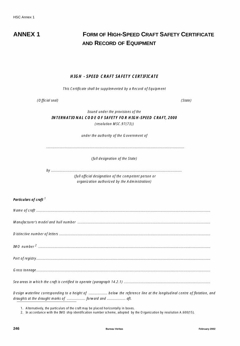
HSC Annex 1
ANNEX 1 FORM OF HIGH-SPEED CRAFT SAFETY CERTIFICATE
AND RECORD OF EQUIPMENT
HIGH - SPEED CRAFT SAFETY CERTIFICATE
This Certificate shall be supplemented by a Record of Equipment
(Official seal) (State)
Issued under the provisions of the
INTERNATIONAL CODE OF SAFETY FOR HIGH-SPEED CRAFT, 2000(resolution MSC.97(73))
under the authority of the Government of
......................................................................................................................................
(full designation of the State)
by ...............................................................................................................................
(full official designation of the competent person or organization authorized by the Administration)
Particulars of craft 1
Name of craft .........................................................................................................................................................................
Manufacturer’s model and hull number .................................................................................................................................
Distinctive number of letters ...................................................................................................................................................
IMO number 2 .......................................................................................................................................................................
Port of registry.........................................................................................................................................................................
Gross tonnage.........................................................................................................................................................................
Sea areas in which the craft is certified to operate (paragraph 14.2.1) ....................................................................................
Design waterline corresponding to a height of .................. below the reference line at the longitudinal centre of flotation, and
draughts at the draught marks of .................. forward and .................. aft.
1. Alternatively, the particulars of the craft may be placed horizontally in boxes.2. In accordance with the IMO ship identification number scheme, adopted by the Organization by resolution A.600(15).
246 Bureau Veritas February 2002
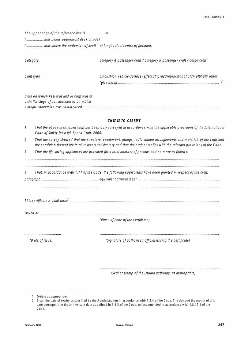
HSC Annex 1
The upper edge of the reference line is .................. at
(................. mm below uppermost deck at side) 1
(................. mm above the underside of keel) 1 at longitudinal centre of flotation.
Category category A passenger craft / category B passenger craft / cargo craft1
Craft type air-cushion vehicle/surface- effect ship/hydrofoil/monohull/multihull/ other
(give detail ................................................................................................... )1
Date on which keel was laid or craft was at a similar stage of construction or on which a major conversion was commenced .....................................................................................................................................
THIS IS TO CERTIFY
1 That the above-mentioned craft has been duly surveyed in accordance with the applicable provisions of the International
Code of Safety for High Speed Craft, 2000.
2 That the survey showed that the structure, equipment, fittings, radio station arrangements and materials of the craft andthe condition thereof are in all respects satisfactory and that the craft complies with the relevant provisions of the Code.
3 That the life-saving appliances are provided for a total number of persons and no more as follows:
...............................................................................................................................................................................................
...............................................................................................................................................................................................
4 That, in accordance with 1.11 of the Code, the following equivalents have been granted in respect of the craft:
paragraph ....................................................... equivalent arrangement ................................................................................
...................................................... ...........................................................................
This certificate is valid until2 ...................................................................................................................................................
Issued at .................................................................................................................................................................................
(Place of issue of the certificate)
.................................... .....................................................................................................................
(Date of issue) (Signature of authorized official issuing the certificate)
..................................................................................................................... (Seal or stamp of the issuing authority, as appropriate)
1. Delete as appropriate.2. Insert the date of expiry as specified by the Administration in accordance with 1.8.4 of the Code. The day and the month of this
date correspond to the anniversary date as defined in 1.4.3 of the Code, unless amended in accordance with 1.8.12.1 of the Code.
February 2002 Bureau Veritas 247

HSC Annex 1
Endorsement for periodical surveys
This is to certify that, at a survey required by 1.5 of the Code, this craft was found to comply with the relevant provisions of theCode.
Periodical survey: Signed:..........................................................................................................
..................................................................................................................... (Signature of authorized official)
Place:............................................................................................................
Date: ............................................................................................................
.....................................................................................................................
(Seal or stamp of Authority, as appropriate)
Periodical survey: Signed:..........................................................................................................
.....................................................................................................................
(Signature of authorized official)
Place:............................................................................................................
Date: ............................................................................................................
.....................................................................................................................
(Seal or stamp of Authority, as appropriate)
248 Bureau Veritas February 2002

HSC Annex 1
Endorsement to extend the Certificate if valid for less than 5 years where 1.8.8 of the Code applies
This craft complies with the relevant requirements of the Code, and this Certificate shall, in accordance with 1.8.8 of the Code,be accepted as valid until ............................... ......................................................................................................................
Signed: ......................................................................................................... (Signature of authorized official)
Place: ...........................................................................................................
Date: ...........................................................................................................
.....................................................................................................................
(Seal or stamp of Authority, as appropriate)
Endorsement where the renewal survey has been completed and 1.8.9 of the Code applies
This craft complies with the relevant requirements of the Code, and this Certificate shall, in accordance with 1.8.9 of the Code,be accepted as valid until ......................................................................................................................................................
Signed: ......................................................................................................... (Signature of authorized official)
Place: ...........................................................................................................
Date: ...........................................................................................................
.....................................................................................................................
(Seal or stamp of Authority, as appropriate)
Endorsement to extend the validity of the Certificate until reaching the port of survey where 1.8.10 of the Code applies
This Certificate shall, in accordance with 1.8.10 of the Code, be accepted as valid until ........................................................
Signed: ........................................................................................................ (Signature of authorized official)
Place: ...........................................................................................................
Date: ...........................................................................................................
.....................................................................................................................
(Seal or stamp of Authority, as appropriate)
February 2002 Bureau Veritas 249

HSC Annex 1
Endorsement for the advancement of the anniversary date where 1.8.12 of the Code applies
In accordance with 1.8.12 of the Code, the new anniversary date is
Signed:..........................................................................................................
(Signature of authorized official)Place:............................................................................................................Date: ............................................................................................................
..................................................................................................................... (Seal or stamp of Authority, as appropriate)
In accordance with 1.8.13 of the Code, the new anniversary date is ......................................................................................
Signed:.......................................................................................................... (Signature of authorized official)Place:............................................................................................................
Date: ............................................................................................................
..................................................................................................................... (Seal or stamp of Authority, as appropriate)
250 Bureau Veritas February 2002
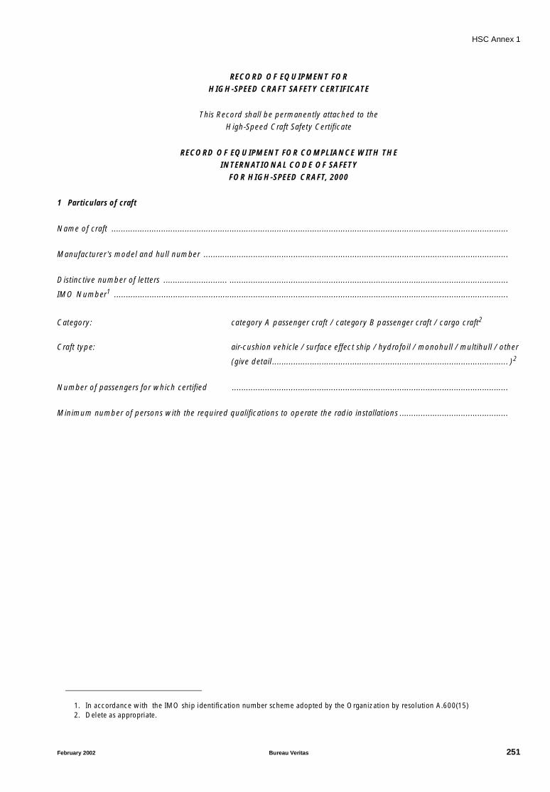
HSC Annex 1
RECORD OF EQUIPMENT FOR HIGH-SPEED CRAFT SAFETY CERTIFICATE
This Record shall be permanently attached to theHigh-Speed Craft Safety Certificate
RECORD OF EQUIPMENT FOR COMPLIANCE WITH THEINTERNATIONAL CODE OF SAFETY
FOR HIGH-SPEED CRAFT, 2000
1 Particulars of craft
Name of craft ........................................................................................................................................................................
Manufacturer’s model and hull number .................................................................................................................................
Distinctive number of letters ........................... ......................................................................................................................
IMO Number1 .......................................................................................................................................................................
Category: category A passenger craft / category B passenger craft / cargo craft2
Craft type: air-cushion vehicle / surface effect ship / hydrofoil / monohull / multihull / other
(give detail.................................................................................................... )2
Number of passengers for which certified .....................................................................................................................
Minimum number of persons with the required qualifications to operate the radio installations ..............................................
1. In accordance with the IMO ship identification number scheme adopted by the Organization by resolution A.600(15)2. Delete as appropriate.
February 2002 Bureau Veritas 251

HSC Annex 1
2 Details of life-saving appliances
1 Total number of persons for which life-saving appliances are provided
2 Total number of lifeboats
2.1 Total number of persons accommodated by them
2.2 Number of partially enclosed lifeboats complying with section 4.5 of the LSA Code
2.3 Number of totally enclosed lifeboats complying with sections 4.6 and 4.7 of the LSA Code
2.4 Other lifeboats
2.4.1 Number
2.4.2 Type
3 Number of rescue boats
3.1 Number of rescue boats which are included in the total lifeboats shown above
4 Liferafts complying with sections 4.1 to 4.3 of the LSA Code for which suitable means of launching are provided
4.1 Number of liferafts
4.2 Number of persons accommodated by them
5 Open reversible liferafts (Annex 11 of the Code)
5.1 Number of liferafts
5.2 Number of persons accommodated by them
6 Number of Marine Evacuation System (MES)
6.1 Number of persons served by them
7 Number of lifebuoys
8 Number of lifejackets
8.1 Number suitable for adults
8.2 Number suitable for children
9 Immersion suits
9.1 Total number
9.2 Number of suits complying with the requirements for lifejackets
10 Number of anti-exposure suits
10.1 Total number
10.2 Number of suits complying with the requirements for lifejackets
11 Radio installations used in life-saving appliances
11.1 Number of radar transponders
11.2 Number of two-way VHF radiotelephone apparatus
252 Bureau Veritas February 2002

HSC Annex 1
3 Details of navigational systems and equipment
1.1 Magnetic compass
1.2 Transmitting heading device (THD)
1.3 Gyro-compass
2 Speed and distance measuring device
3 Echo-sounding device
4.1 9 GHz radar
4.2 Second radar (3 GHz/9 GHz1)
4.3 Automatic radar plotting aid (ARPA)/ Automatic tracking aid (ATA)1
5 Receiver for global navigation satellite system/ Terrestrial navigation system/ Other means ofposition fixing 1, 2
6.1 Rate of turn indicator
6.2 Rudder angle indicator/Direction of steering thrust indicator1
7.1 Nautical charts/Electronic Chart Display and Information System (ECDIS)1
7.2 Back-up arrangements for ECDIS
7.3 Nautical publications
7.4 Back-up arrangement for nautical publications
8 Search light
9 Daylight signalling lamp
10 Night vision equipment
11 Means to show the mode of the propulsion systems
12 Automatic steering aid (Automatic pilot)
13 Radar reflector/ Other means1,2
14 Sound reception system
15 Automatic identification system (AIS)
16 Voyage data recorder (VDR)
February 2002 Bureau Veritas 253

HSC Annex 1
4 Details of radio facilities
Item Actual provision
1 Primary systems
1.1 VHF radio installation:
1.1.1 DSC encoder
1.1.2 DSC watch receiver
1.1.3 Radiotelephony
1.2 MF radio installation:
1.2.1 DSC encoder
1.2.2 DSC watch receiver
1.2.3 Radiotelephony
1.3 MF/HF radio installation:
1.3.1 DSC encoder
1.3.2 DSC watch receiver
1.3.3 Radiotelephony
1.3.4 Direct-printing radiotelegraphy
1.4 INMARSAT ship earth station
2 Secondary means of alerting
3 Facilities for reception of maritime safety information
3.1 NAVTEX receiver
3.2 EGC receiver
3.3 HF direct-printing radiotelegraph receiver
4 Satellite EPIRB
4.1 COSPAS-SARSAT
4.2 INMARSAT
5 VHF EPIRB
6 Ship’s radar transponder
254 Bureau Veritas February 2002
HSC Annex 1
5 Methods used to ensure availability or radio facilities (paragraphs 14.15.6, 14.15.7 and 14.15.8 of the Code)
5.1 Duplication of equipment ................................................................................................................................................
5.2 Shore-based maintenance ................................................................................................................................................
5.3 At-sea maintenance capability .........................................................................................................................................
THIS IS TO CERTIFY that this Record is correct in all respects
Issued at ......................................................................................................................................... (Place of issue of Record)
...................................................................... .................................................................................. (Date of issue) (Signature of duly authorized official issuing the record)
.................................................................................................................... (Seal or stamp of the issuing authority, as appropriate)
February 2002 Bureau Veritas 255
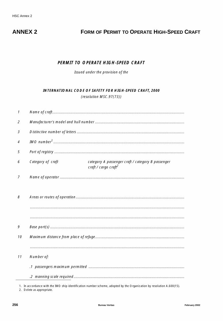
HSC Annex 2
ANNEX 2 FORM OF PERMIT TO OPERATE HIGH-SPEED CRAFT
PERMIT TO OPERATE HIGH-SPEED CRAFT
Issued under the provision of the
INTERNATIONAL CODE OF SAFETY FOR HIGH-SPEED CRAFT, 2000
(resolution MSC.97(73))
1 Name of craft............................................................................................................................
2 Manufacturer’s model and hull number ....................................................................................
3 Distinctive number of letters .....................................................................................................
4 IMO number1 ...........................................................................................................................
5 Port of registry ..........................................................................................................................
6 Category of craft category A passenger craft / category B passenger craft / cargo craft2
7 Name of operator .....................................................................................................................
8 Areas or routes of operation ......................................................................................................
.................................................................................................................................................
.................................................................................................................................................
9 Base port(s) ..............................................................................................................................
10 Maximum distance from place of refuge....................................................................................
.................................................................................................................................................
11 Number of:
.1 passengers maximum permitted ..........................................................................................
.2 manning scale required........................................................................................................
1. In accordance with the IMO ship identification number scheme, adopted by the Organization by resolution A.600(15).2. Delete as appropriate.
256 Bureau Veritas February 2002

HSC Annex 2
12 Worst intended conditions ........................................................................................................
.................................................................................................................................................
.................................................................................................................................................
13 Other operational restrictions....................................................................................................
This permit confirms that the service mentioned above has been found to be in accordance with the gen-eral requirements of 1.2.2 to 1.2.7 of the Code.
THIS PERMIT is issued under the authority of the Government of ........................................................
.............................................................................................................................................................
THIS PERMIT is valid until ....................................................................................................................subject to the High-Speed Craft Safety Certificate remaining valid
Issued at .....................................................................
(Place of issue of permit)
............................................ ..................................................................
(Date of issue) (Signature of duly authorized official issuing the permit)
..........................................................................................
(Seal or stamp of the issuing authority, as appropriate)
February 2002 Bureau Veritas 257
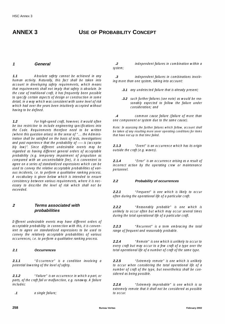
HSC Annex 3
ANNEX 3 USE OF PROBABILITY CONCEPT
1 General
1.1 Absolute safety cannot be achieved in anyhuman activity. Naturally, this fact shall be taken intoaccount in developing safety requirements, which meansthat requirements shall not imply that safety is absolute. Inthe case of traditional craft, it has frequently been possibleto specify certain aspects of design or construction in somedetail, in a way which was consistent with some level of riskwhich had over the years been intuitively accepted withouthaving to be defined.
1.2 For high-speed craft, however, it would oftenbe too restrictive to include engineering specifications intothe Code. Requirements therefore need to be written(where this question arises) in the sense of “… the Adminis-tration shall be satisfied on the basis of tests, investigationsand past experience that the probability of ––– is (accepta-bly low)”. Since different undesirable events may beregarded as having different general orders of acceptableprobability (e.g. temporary impairment of propulsion ascompared with an uncontrollable fire), it is convenient toagree on a series of standardized expressions which can beused to convey the relative acceptable probabilities of vari-ous incidents, i.e. to perform a qualitative ranking process.A vocabulary is given below which is intended to ensureconsistency between various requirements, where it is nec-essary to describe the level of risk which shall not beexceeded.
2 Terms associated withprobabilities
Different undesirable events may have different orders ofacceptable probability. in connection with this, it is conven-ient to agree on standardized expressions to be used toconvey the relatively acceptable probabilities of variousoccurrences, i.e. to perform a qualitative ranking process.
2.1 Occurrences
2.1.1 “Occurrence” is a condition involving apotential lowering of the level of safety.
2.1.2 “Failure” is an occurrence in which a part, orparts, of the craft fail or malfunction, e.g. runaway. A failureincludes:
.1 a single failure;
.2 independent failures in combination within asystem;
.3 independent failures in combinations involv-ing more than one system, taking into account:
.3.1 any undetected failure that is already present;
.3.2 such further failures (see note) as would be rea-sonably expected to follow the failure underconsideration; and
.4 common cause failure (failure of more thanone component or system due to the same cause).
Note: In assessing the further failures which follow, account shallbe taken of any resulting more sever operating conditions for itemsthat have not up to that time failed.
2.1.3 “Event” is an occurrence which has its originoutside the craft (e.g. waves).
2.1.4 “Error” is an occurrence arising as a result ofincorrect action by the operating crew or maintenancepersonnel.
2.2 Probability of occurrences
2.2.1 “Frequent” is one which is likely to occuroften during the operational life of a particular craft.
2.2.2 “Reasonably probable” is one which isunlikely to occur often but which may occur several timesduring the total operational life of a particular craft.
2.2.3 “Recurrent” is a term embracing the totalrange of frequent and reasonably probable.
2.2.4 “Remote” is one which is unlikely to occur toevery craft but may occur to a few craft of a type over thetotal operational life of a number of craft of the same type.
2.2.5 “Extremely remote” is one which is unlikelyto occur when considering the total operational life of anumber of craft of the type, but nevertheless shall be con-sidered as being possible.
2.2.6 “Extremely improbable” is one which is soextremely remote that it shall not be considered as possibleto occur.
258 Bureau Veritas February 2002

HSC Annex 3
2.3 Effects
2.3.1 “Effect” is a situation arising as a result of anoccurrence.
2.3.2 “Minor effect” is an effect which may arisefrom a failure, an event, or an error, as defined in 2.1.2,2.1.3, 2.1.4, which can be readily compensated for by theoperating crew. It may involve:
.1 a small increase in the operational duties ofthe crew or in their difficulty in performing their duties; or
.2 a moderate degradation in handling charac-teristics; or
.3 slight modification of the permissible operat-ing conditions.
2.3.3 “Major effect” is an effect which produces:
.1 a significant increase in the operationalduties of the crew or in their difficulty in performing theirduties which by itself shall not be outside the capability of acompetent crew provided that another major effect doesnot occur at the same time; or
.2 significant degradation in handling character-istics; or
.3 significant modification of the permissibleoperating conditions, but will not remove the capability tocomplete a safe journey without demanding more than nor-mal skill on the part of the operating crew.
2.3.4 “Hazardous effect” is an effect whichproduces:
.1 a dangerous increase in the operationalduties of the crew or in their difficulty in performing theirduties of such magnitude that they cannot reasonably beexpected to cope with them and will probably require out-side assistance; or
.2 dangerous degradation of handling charac-teristics; or
.3 dangerous degradation of the strength of thecraft; or
.4 marginal conditions for, or injury to, occu-pants; or
.5 an essential need for outside rescueoperations.
2.3.5 “Catastrophic effect” is an effect whichresults in the loss of the craft and/or in fatalities.
2.4 Safety level
“Safety level” is a numerical value characterizing the rela-tionship between craft performance represented ashorizontal single-amplitude acceleration (g) and the severityof acceleration-load effects on standing and sitting humans.The safety levels and the corresponding severity of effectson passengers and safety criteria for craft performance shallbe as defined in Table 1.
Table 1
EffectCriteria not to be exceeded
CommentsType of load Value
LEVEL 1MINOR EFFECTModerate degradation of safety
Maximum accelerationmeasured horizontally (1)
0.20 g 0.08 g : Elderly person will keep balance when holding
0.15 g : Mean person will keep balance when holding
0.15 g : Sitting person will start holding
LEVEL 2MAJOR EFFECTSignificant degradation of safety
Maximum accelerationmeasured horizontally (1)
0.35 g 0.25 g : Maximum load for mean person keepingbalance when holding
0.45 g : Mean person falls out of seat when not wearing seat belts
LEVEL 3HAZARDOUS EFFECTMajor degradation of safety
Collision design conditioncalculatedMaximum structural design load, based on vertical accel-eration at centre of gravity
Ref. 4.3.3
Ref. 4.3.1
Risk of injury to passengers; safe emergency operation after collision
1.0 g : Degradation of passenger safety
LEVEL 4CATASTROPHIC EFFECT
Loss of craft or/and fatalities
(1) The accelerometers used shall have an accuracy of at least 5% full scale and shall not have a frequency response of less than 20Hz. The sampling frequency should not be less than 5 times the maximum frequency response. Anti-aliasing filters, if used, should have a passband equal to the frequency response.
g : gravity acceleration (9.81 m/s2).
February 2002 Bureau Veritas 259

HSC Annex 3
3 Numerical values
Where numerical probabilities are used in assessing compli-ance with requirements using the terms similar to thosegiven above, the following approximate values may be usedas guidelines to assist in providing a common point of refer-ence. The probabilities quoted shall be on an hourly or per-journey basis, depending on which is more appropriate tothe assessment in question.
Table 2
Frequent More than 10-3
Reasonably probable 10-3 to 10-5
Remote 10-5 to 10-7
Extremely remote 10-7 to 10-9
Extremely improbable Whilst no approximate numerical probability is given for this, the fig-ures used shall be substantially less than 10-9
Note: Different occurrences may have different acceptable probabili-ties, according to the severity of their consequences (see Table 3).
260 Bureau Veritas February 2002
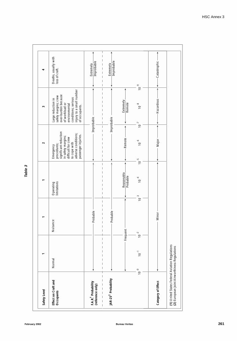
HSC Annex 3
Tab
le3
Effe
ct o
n C
raft
and
O
ccup
ants
F.A
.R.
Prob
abili
ty
(ref
eren
ce o
nly)
JAR
-25
Pro
babi
lity
Cat
egor
y of
Eff
ect
11
23
4Sa
fety
Lev
el
Min
orM
ajor
Haz
ardo
usC
atas
trop
hic
1
Nor
mal
Nui
sanc
eO
pera
ting
limita
tions
Emer
genc
y pr
oced
ures
;si
gnifi
cant
red
uctio
nin
saf
ety
mar
gins
;di
fficu
lt fo
r cr
ewto
cop
e w
ith
adve
rse
cond
ition
s;pa
ssen
ger
inju
ries
.
Larg
e re
duct
ion
insa
fety
mar
gins
; cre
wov
er-b
urde
n be
caus
eof
wor
kloa
d or
envi
ronm
enta
lco
nditi
ons;
ser
ious
inju
ry to
a s
mal
l num
ber
of o
ccup
ants
.
Dea
ths,
usu
ally
with
loss
of c
raft.
10-0
10-5
10-7
10-9
10-1
10-2
10-3
10-4
10-6
10-8
Impr
obab
le
Impr
obab
leEx
trem
ely
Impr
obab
le
Extr
emel
yIm
prob
able
Extr
emel
yR
emot
eR
emot
eR
easo
nabl
yPr
obab
leFr
eque
nt
2
1
Prob
able
Prob
able
(1)
Uni
ted
Stat
es F
eder
al A
viat
ion
Reg
ulat
ions
(2)
Euro
pean
Join
t Air
wor
thin
ess
Reg
ulat
ions
February 2002 Bureau Veritas 261

HSC Annex 4
ANNEX 4 PROCEDURES FOR FAILURE MODE AND EFFECTS
ANALYSIS
C0 Document to be submitted
FMEA report, including FMEA worksheets.
1 Introduction
1.1 In the case of traditional craft, it has beenpossible to specify certain aspects of design or constructionin some level of detail, in a way which was consistent withsome level of risk which had over the years been intuitivelyaccepted without having to be defined.
1.2 With the development of large high-speedcraft, this required experience has not been widely availa-ble. However, with the now broad acceptance of theprobabilistic approach to safety assessments within industryas a whole, it is proposed that an analysis of failure perform-ance may be used to assist in the assessment of the safety ofoperation of high-speed craft.
1.3 A practical, realistic and documented assess-ment of the failure characteristics of the craft and itscomponent systems shall be undertaken with the aim ofdefining and studying the important failure conditions thatmay exist.
1.4 This annex describes a failure mode andeffects analysis (FMEA) and gives guidance as to how it maybe applied by:
.1 explaining basic principles;
.2 providing the procedural steps necessary toperform an analysis;
.3 identifying appropriate terms, assumptions,measures and failure modes; and
.4 providing examples of the necessaryworksheets.
1.5 FMEA for high-speed craft is based on a sin-gle-failure concept under which each system at variouslevels of a system's functional hierarchy is assumed to fail byone probable cause at a time. The effects of the postulatedfailure are analysed and classified according to their sever-ity. Such effects may include secondary failures (or multiplefailures) at other level(s). Any failure mode which maycause a catastrophic effect to the craft shall be guarded
against by system or equipment redundancy unless theprobability of such failure is extremely improbable (refer tosection 13). For failure modes causing hazardous effects,corrective measures may be accepted in lieu. A test pro-gramme shall be drawn to confirm the conclusions ofFMEA.
1.6 Whilst FMEA is suggested as one of the mostflexible analysis techniques, it is accepted that there areother methods which may be used and which in certain cir-cumstances may offer an equally comprehensive insightinto particular failure characteristics.
2 Objectives
2.1 The primary objective of FMEA is to providea comprehensive, systematic and documented investigationwhich establishes the important failure conditions of thecraft and assesses their significance with regard to the safetyof the craft, its occupants and the environment.
2.2 The main aims of undertaking the analysisare to:
.1 provide the Administration with the results ofa study into the craft's failure characteristics so as to assist inan assessment of the levels of safety proposed for the craft'soperation;
.2 provide craft operators with date to generatecomprehensive training, operational and maintenance pro-grammes and documentation; and
.3 provide craft and system designers with datato audit their proposed designs.
3 Scope of application
3.1 FMEA shall be conducted for each high-speed craft, before its entry into service, in respect of thesystems as required under the provisions of 5.2, 9.1.10,12.1.1 and 16.2.6 of this Code.
3.2 For craft of the same design and having thesame equipment, one FMEA on the lead craft will be suffi-cient, but each of the craft shall be subject to the sameFMEA conclusion trials.
262 Bureau Veritas February 2002

HSC Annex 4
4 System failure mode and effectsanalysis
4.1 Before proceeding with a detailed FMEA intothe effects of the failure of the system elements on the sys-tem functional output it is necessary to perform a functionalfailure analysis of the craft's important systems. In this wayonly systems which fail the functional failure analysis needto be investigated by a more detailed FMEA.
4.2 When conducting a system FMEA the follow-ing typical operational modes within the normal designenvironmental conditions of the craft shall be considered:
.1 normal seagoing conditions at full speed;
.2 maximum permitted operating speed in con-gested waters; and
.3 manoeuvring alongside.
4.3 The functional interdependence of these sys-tems shall also be described in either block diagrams orfault-tree diagrams or in a narrative format to enable the fail-ure effects to be understood. As far as applicable, each ofthe systems to be analysed is assumed to fail in the followingfailure modes:
.1 complete loss of function;
.2 rapid change to maximum or minimumoutput;
.3 uncontrolled or varying output;
.4 premature operation;
.5 failure to operate at a prescribed time; and
.6 failure to cease operation at a prescribedtime.
Depending on the system under consideration, other failuremodes may have to be taken into account.
4.4 If a system can fail without any hazardous orcatastrophic effect, there is no need to conduct a detailedFMEA into the system architecture. For systems whose indi-vidual failure can cause hazardous or catastrophic effectsand where a redundant system is not provided, a detailedFMEA as described in the following paragraphs shall be fol-lowed. Results of the system functional failure analysis shallbe documented and confirmed by a practical test pro-gramme drawn up from the analysis.
4.5 Where a system, the failure of which maycause a hazardous or catastrophic effect, is provided with aredundant system, a detailed FMEA may not be requiredprovided that:
.1 the redundant system can be put into opera-tion or can take over the failed system within the time-limitdictated by the most onerous operational mode in 4.2 with-out hazarding the craft;
.2 the redundant system is completely inde-pendent from the system and does not share any commonsystem element the failure of which would cause failure ofboth the system and the redundant system. Common sys-tem element may be acceptable if the probability of failurecomplies with section 13; and
.3 the redundant system may share the samepower source as the system. In such case an alternativepower source shall be readily available with regard to therequirement of .1.
The probability and effects of operator error to bring in theredundant system shall also be considered.
5 Equipment failure mode andeffects analysis
The systems to be subject to a more detailed FMEA investi-gation at this stage shall include all those that have failed thesystem FMEA and may include those that have a veryimportant influence on the safety of the craft and its occu-pants and which require an investigation at a deeper levelthan that undertaken in the system functional failure analy-sis. These systems are often those which have beenspecifically designed or adapted for the craft, such as thecraft's electrical and hydraulic systems.
6 Procedures
The following steps are necessary to perform FMEA:
.1 to define the system to be analysed;
.2 to illustrate the interrelationships of func-tional elements of the system by means of block diagrams;
.3 to identify all potential failure modes andtheir causes;
.4 to evaluate the effects on the system of eachfailure mode;
.5 to identify failure detection methods;
.6 to identify corrective measures for failure modes;
.7 to assess the probability of failures causinghazardous or catastrophic effects, where applicable;
.8 to document the analysis;
.9 to develop a test programme;
.10 to prepare FMEA report.
February 2002 Bureau Veritas 263

HSC Annex 4
7 System definition
The first step in an FMEA study is a detailed study of the sys-tem to be analysed through the use of drawings andequipment manuals. A narrative description of the systemand its functional requirements shall be drawn up includingthe following information:
.1 general description of system operation andstructure;
.2 functional relationship among the systemelements;
.3 acceptable functional performance limits ofthe system and its constituent elements in each of the typi-cal operational modes; and
.4 system constraints.
8 Development of system blockdiagrams
8.1 The next step is to develop block diagram(s)showing the functional flow sequence of the system, bothfor technical understanding of the functions and operationof the system and for the subsequent analysis. As a mini-mum the block diagram shall contain:
.1 breakdown of the system into major sub-sys-tems or equipment;
.2 all appropriate labelled inputs and outputsand identification numbers by which each sub-system isconsistently referenced; and
.3 all redundancies, alternative signal paths andother engineering features which provide “fail-safe”measures.
An example of a system block diagram is given atAppendix 1.
8.2 It may be necessary to have a different set ofblock diagrams prepared for each operational mode.
9 Identification of failure modes,causes and effects
9.1 Failure mode is the manner by which a fail-ure is observed. It generally describes the way the failureoccurs and its impact on the equipment or system. As anexample, a list of failure modes is given in table 1. The fail-ure modes listed in table 1 can describe the failure of anysystem element in sufficiently specific terms. When used inconjunction with performance specifications governing theinputs and outputs on the system block diagram, all poten-
tial failure modes can be thus identified and described.Thus, for example, a power supply may have a failure modedescribed as “loss of output” (29), and a failure cause“open (electrical)” (31).
9.2 A failure mode in a system element couldalso be the failure cause of a system failure. For example,the hydraulic line of a steering gear system might have a fail-ure mode of “external leakage” (10). This failure mode ofthe hydraulic line could become a failure cause of the steer-ing gear system's failure mode “loss of output” (29).
9.3 Each system shall be considered in a top-down approach, starting from the system's functional out-put, and failure shall be assumed by one possible cause at atime. Since a failure mode may have more than one cause,all potential independent causes for each failure mode shallbe identified.
9.4 If major systems can fail without any adverseeffect there is no need to consider them further unless thefailure can go undetected by an operator. To decide thatthere is no adverse effect does not mean just the identifica-tion of system redundancy. The redundancy shall be shownto be immediately effective or brought on line with negligi-ble time lag. In addition, if the sequence is:“failure–alarm–operator action–start of back up–back up inservice”,the effects of delay shall be considered.
10 Failure effects
10.1 The consequence of a failure mode on theoperation, function, or status of an equipment or a system iscalled a “failure effect”. Failure effects on a specific sub-sys-tem or equipment under consideration are called localfailure effects”. The evaluation of local failure effects willhelp to determine the effectiveness of any redundant equip-ment or corrective action at that system level. In certaininstances, there may not be a local effect beyond the failuremode itself.
10.2 The impact of an equipment or sub-systemfailure on the system output (system function) is called an“end effect”. End effects shall be evaluated and their sever-ity classified in accordance with the following categories:
.1 catastrophic;
.2 hazardous;
.3 major; and
.4 minor.
The definitions of these four categories of failure effects aregiven in 2.3 of annex 3 of this Code.
264 Bureau Veritas February 2002
HSC Annex 4
10.3 If the end effect of a failure is classified ashazardous or catastrophic, back-up equipment is usuallyrequired to prevent or minimize such effect. For hazardousfailure effects corrective operational procedures may beaccepted.
11 Failure detection
11.1 The FMEA study in general only analyses fail-ure effects based on a single failure in the system andtherefore a failure detection means, such as visual or audi-ble warning devices, automatic sensing devices, sensinginstrumentation or other unique indications shall beidentified.
11.2 Where the system element failure is non-detectable (i.e. a hidden fault or any failure which does notgive any visual or audible indication to the operator) andthe system can continue with its specific operation, theanalysis shall be extended to determine the effects of a sec-ond failure, which in combination with the firstundetectable failure may result in a more severe failureeffect, e.g., hazardous or catastrophic effect.
12 Corrective measures
12.1 The response of any back-up equipment, orany corrective action initiated at a given system level to pre-vent or reduce the effect of the failure mode of a systemelement or equipment, shall also be identified andevaluated.
12.2 Provisions which are features of the design atany system level to nullify the effects of a malfunction or fail-ure, such as controlling or deactivating system elements tohalt generation or propagation of failure effects, or activat-ing back-up or standby items or systems, shall be described.Corrective design provisions include:
.1 redundancies that allow continued and safeoperation;
.2 safety devices, monitoring or alarm provi-sions, which permit restricted operation or limit damage;and
.3 alternative modes of operation.
12.3 Provisions which require operator action tocircumvent or mitigate the effects of the postulated failureshall be described. The possibility and effect of operator
error shall be considered, if the corrective action or the initi-ation of the redundancy requires operator input, whenevaluating the means to eliminate the local failure effects.
12.4 It shall be noted that corrective responsesacceptable in one operational mode may not be acceptableat another, e.g., a redundant system element with consider-able time lag to be brought into line, while meeting theoperational mode “normal seagoing conditions at fullspeed” may result in a catastrophic effect in another opera-tional mode, e.g., “maximum permitted operating speed incongested water”.
13 Use of probability concept
13.1 If corrective measures or redundancy asdescribed in preceding paragraphs are not provided for anyfailure, as an alternative the probability of occurrence ofsuch failure shall meet the following criteria of acceptance:
.1 a failure mode which results in a catastrophiceffect shall be assessed to be extremely improbable;
.2 a failure mode assessed as extremely remoteshall not result in worse than hazardous effects; and
.3 a failure mode assessed as either frequent orreasonably probable shall not result in worse than minoreffects.
13.2 Numerical values for various levels of proba-bilities are laid down in section 3 of annex 3 of this Code. Inareas where there are no data from craft to determine thelevel of probabilities of failure other sources can be usedsuch as:
.1 workshop test, or
.2 history of reliability used in other areas undersimilar operating conditions, or
.3 mathematical model if applicable.
14 Documentation
14.1 It is helpful to perform FMEA on work-sheet(s) as shown in appendix 2.
14.2 The worksheet(s) shall be organized to firstdisplay the highest system level and then proceed downthrough decreasing system levels.
February 2002 Bureau Veritas 265
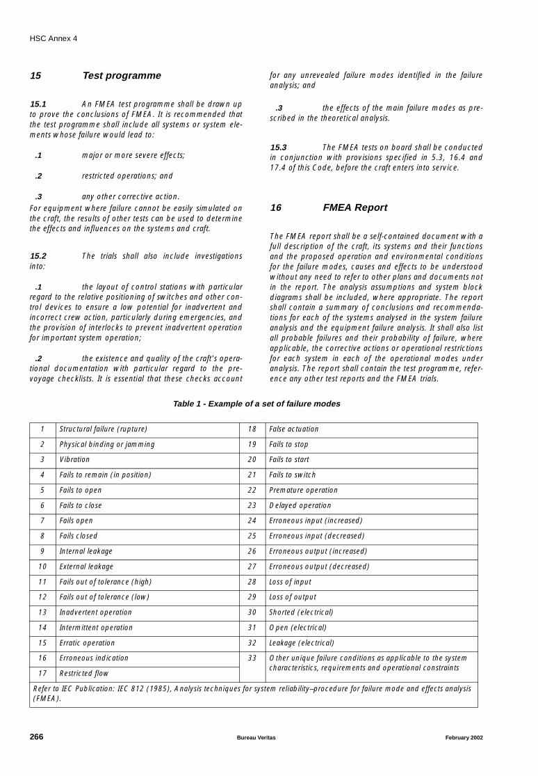
HSC Annex 4
15 Test programme
15.1 An FMEA test programme shall be drawn upto prove the conclusions of FMEA. It is recommended thatthe test programme shall include all systems or system ele-ments whose failure would lead to:
.1 major or more severe effects;
.2 restricted operations; and
.3 any other corrective action.For equipment where failure cannot be easily simulated onthe craft, the results of other tests can be used to determinethe effects and influences on the systems and craft.
15.2 The trials shall also include investigationsinto:
.1 the layout of control stations with particularregard to the relative positioning of switches and other con-trol devices to ensure a low potential for inadvertent andincorrect crew action, particularly during emergencies, andthe provision of interlocks to prevent inadvertent operationfor important system operation;
.2 the existence and quality of the craft's opera-tional documentation with particular regard to the pre-voyage checklists. It is essential that these checks account
for any unrevealed failure modes identified in the failureanalysis; and
.3 the effects of the main failure modes as pre-scribed in the theoretical analysis.
15.3 The FMEA tests on board shall be conductedin conjunction with provisions specified in 5.3, 16.4 and17.4 of this Code, before the craft enters into service.
16 FMEA Report
The FMEA report shall be a self-contained document with afull description of the craft, its systems and their functionsand the proposed operation and environmental conditionsfor the failure modes, causes and effects to be understoodwithout any need to refer to other plans and documents notin the report. The analysis assumptions and system blockdiagrams shall be included, where appropriate. The reportshall contain a summary of conclusions and recommenda-tions for each of the systems analysed in the system failureanalysis and the equipment failure analysis. It shall also listall probable failures and their probability of failure, whereapplicable, the corrective actions or operational restrictionsfor each system in each of the operational modes underanalysis. The report shall contain the test programme, refer-ence any other test reports and the FMEA trials.
Table 1 - Example of a set of failure modes
1 Structural failure (rupture) 18 False actuation
2 Physical binding or jamming 19 Fails to stop
3 Vibration 20 Fails to start
4 Fails to remain (in position) 21 Fails to switch
5 Fails to open 22 Premature operation
6 Fails to close 23 Delayed operation
7 Fails open 24 Erroneous input (increased)
8 Fails closed 25 Erroneous input (decreased)
9 Internal leakage 26 Erroneous output (increased)
10 External leakage 27 Erroneous output (decreased)
11 Fails out of tolerance (high) 28 Loss of input
12 Fails out of tolerance (low) 29 Loss of output
13 Inadvertent operation 30 Shorted (electrical)
14 Intermittent operation 31 Open (electrical)
15 Erratic operation 32 Leakage (electrical)
16 Erroneous indication 33 Other unique failure conditions as applicable to the system characteristics, requirements and operational constraints
17 Restricted flow
Refer to IEC Publication: IEC 812 (1985), Analysis techniques for system reliability–procedure for failure mode and effects analysis (FMEA).
266 Bureau Veritas February 2002
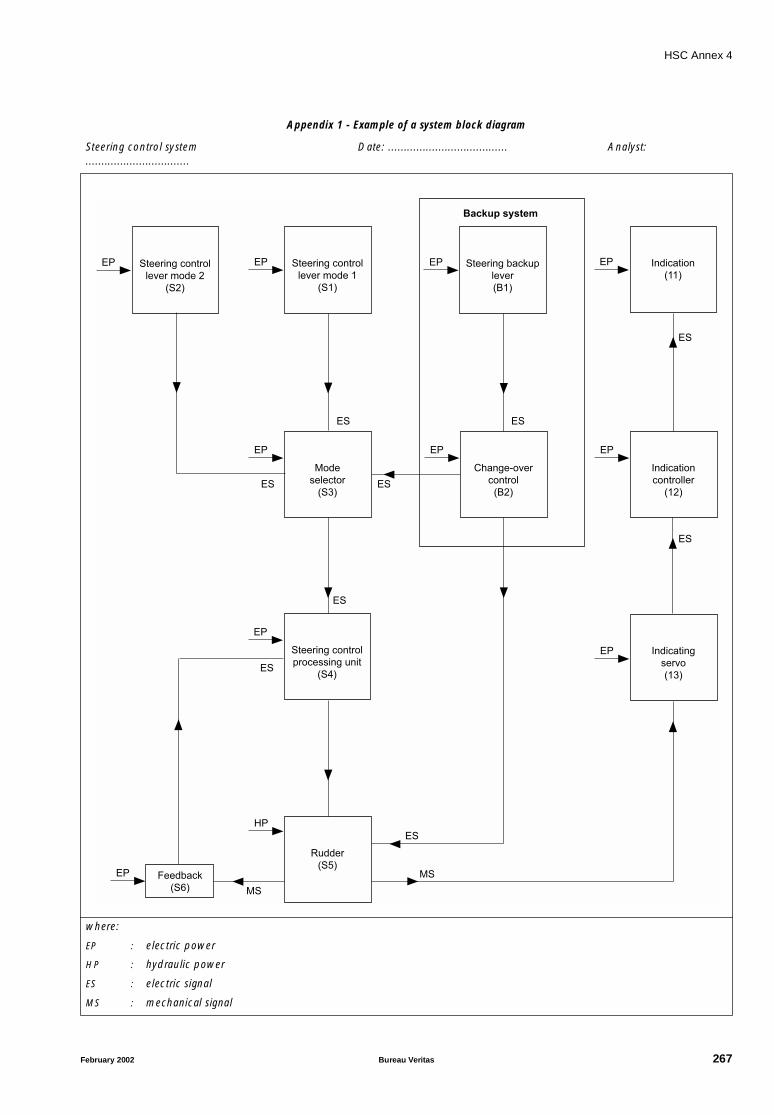
HSC Annex 4
Appendix 1 - Example of a system block diagram
Steering control system Date: ...................................... Analyst: .................................
where:
EP : electric power
HP : hydraulic power
ES : electric signal
MS : mechanical signal
Steering control
lever mode 2
(S2)
EP Steering control
lever mode 1
(S1)
EP Steering backup
lever
(B1)
EP Indication
(11)
EP
Mode
selector
(S3)
EP
Change-over
control
(B2)
EP
Indication
controller
(12)
EP
Backup system
Steering control
processing unit
(S4)
EP
Indicating
servo
(13)
EP
Rudder
(S5)
HP
ES
MSFeedback
(S6) MS
EP
ES
ES ES
ES
ES
ES
ES ES
February 2002 Bureau Veritas 267
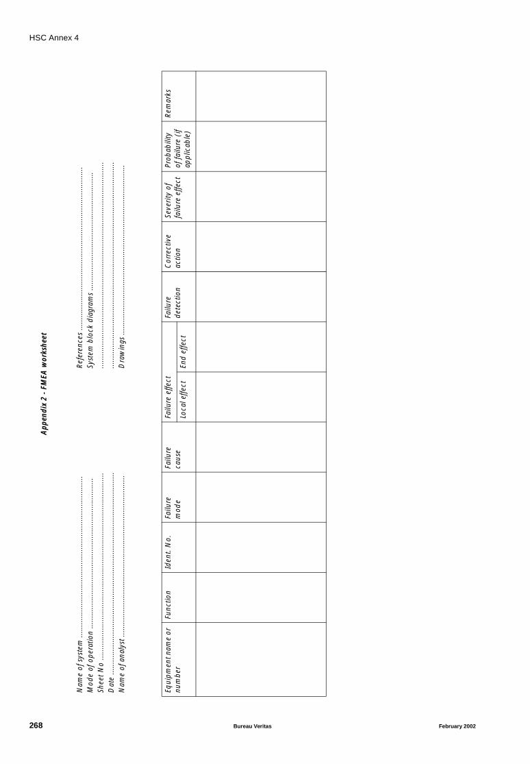
HSC Annex 4
Appen
dix
2 -
FMEA
wor
kshe
et
Nam
e of
sys
tem
.....
......
......
......
......
......
......
......
......
......
......
......
....
Mod
e of
ope
ratio
n ...
......
......
......
......
......
......
......
......
......
......
......
.Sh
eet
No
......
......
......
......
......
......
......
......
......
......
......
......
......
......
...D
ate
......
......
......
......
......
......
......
......
......
......
......
......
......
......
......
....
Nam
e of
ana
lyst
.....
......
......
......
......
......
......
......
......
......
......
......
....
Ref
eren
ces
......
......
......
......
......
......
......
......
......
......
......
......
....
Syst
em b
lock
dia
gram
s ...
......
......
......
......
......
......
......
......
....
......
......
......
......
......
......
......
......
......
......
......
......
......
......
......
......
......
......
......
......
......
......
......
......
......
......
......
......
......
......
......
......
Dra
win
gs ..
......
......
......
......
......
......
......
......
......
......
......
......
.....
Equi
pmen
t nam
e or
nu
mbe
rFu
nctio
nId
ent.
No.
Failu
re
mod
eFa
ilure
ca
use
Failu
re e
ffect
Failu
re
dete
ctio
nC
orre
ctiv
e ac
tion
Seve
rity
of
failu
re e
ffect
Prob
abili
ty
of fa
ilure
(if
appl
icab
le)
Rem
arks
Loca
l effe
ctEn
d e
ffect
268 Bureau Veritas February 2002
HSC Annex 5
ANNEX 5 ICE ACCRETION APPLICABLE TO ALL TYPES OF
CRAFT
1 Icing allowances
1.1 For craft operating in areas where ice accre-tion is likely to occur, the following icing allowance shall bemade in the stability calculations.
.1 30 kg/m2 on exposed weather decks andgangways;
.2 7.5 kg/m2 for projected lateral area of eachside of the craft above the waterplane;
.3 the projected lateral area of discontinuoussurfaces of rail, sundry booms, spars (except masts) and rig-ging and the projected lateral area of other small objectsshall be computed by increasing the total projected area ofcontinuous surfaces by 5% and the static moments of thisarea by 10%;
.4 reduction of stability due to asymmetric iceaccumulations in cross-structure.
1.2 For craft operating in areas where ice accre-tion may be expected:
.1 Within the areas defined in 2.1, 2.3, 2.4 and2.5 known to have icing conditions significantly differentfrom those in 1.1, ice accretion requirements of one half totwice the required allowance may be applied.
.2 Within the area defined in 2.2, where iceaccretion in excess of twice the allowance required by 1.1may be expected, more severe requirements than thosegiven in 1.1 may be applied.
1.3 Information shall be provided in respect ofthe assumptions made in calculating the condition of thecraft in each of the circumstances set out in this annex forthe following:
.1 duration of the voyage in terms of the periodspent in reaching the destination and returning to port; and
.2 consumption rates during the voyage for fuel,water, stores and other consumables.
2 Areas of icing conditions
In the application of 1, the following icing areas shall apply:
.1 The area north of latitude 65° 30′ N,between longitude 28° W and the west coast of Iceland;north of the north coast of Iceland;
north of the rhumb line running from latitude 66° N, longi-tude 15°W to latitude 73° 30′ N, longitude 15° E, north oflatitude 73° 30′ N between longitude 15° E and 35° E, andeast of longitude 35° E, as well as north of latitude 56° N inthe Baltic Sea.
.2 The area north of latitude 43° N bounded inthe west by the North American coast and the east by therhumb line running from latitude 43° N, longitude 48° W tolatitude 63° N, longitude 28° W and thence along longitude28° W.
.3 All sea areas north of the North Americancontinent, west of the areas defined in subparagraphs .1and .2 of this paragraph.
.4 The Bering and Okhotsk Seas and the TartaryStrait during the icing season.
.5 South of latitude 60° S.
A chart to illustrate the areas is attached.
3 Special requirements
Craft intended for operation in areas where ice accretion isknown to occur shall be:
.1 designed to minimize the accretion of ice;and
.2 equipped with such means for removing iceas the Administration may require.
February 2002 Bureau Veritas 269
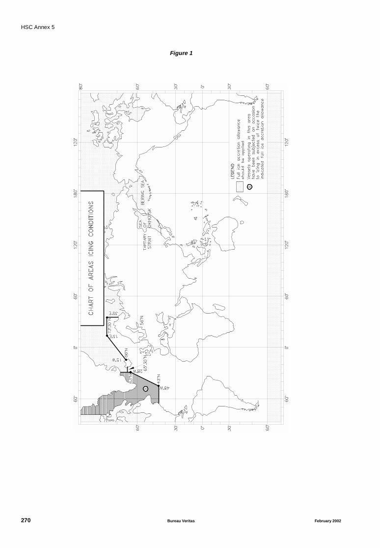
HSC Annex 5
Figure 1
270 Bureau Veritas February 2002
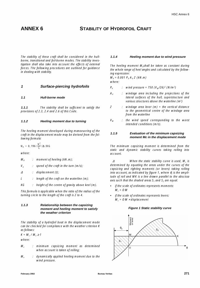
HSC Annex 6
ANNEX 6 STABILITY OF HYDROFOIL CRAFT
The stability of these craft shall be considered in the hull-borne, transitional and foil-borne modes. The stability inves-tigation shall also take into account the effects of externalforces. The following procedures are outlined for guidancein dealing with stability.
1 Surface-piercing hydrofoils
1.1 Hull-borne mode
1.1.1 The stability shall be sufficient to satisfy theprovisions of 2.3, 2.4 and 2.6 of this Code.
1.1.2 Heeling moment due to turning
The heeling moment developed during manoeuvring of thecraft in the displacement mode may be derived from the fol-lowing formula:
where:
MR : moment of heeling (kN.m);
Vo : speed of the craft in the turn (m/s);
∆ : displacement (t);
L : length of the craft on the waterline (m);
KG : height of the centre of gravity above keel (m).
This formula is applicable when the ratio of the radius of theturning circle to the length of the craft is 2 to 4.
1.1.3 Relationship between the capsizingmoment and heeling moment to satisfythe weather criterion
The stability of a hydrofoil boat in the displacement modecan be checked for compliance with the weather criterion Kas follows:
K = Mc / Mv ≥ 1
where:
Mc : minimum capsizing moment as determinedwhen account is taken of rolling;
Mv : dynamically applied heeling moment due to thewind pressure.
1.1.4 Heeling moment due to wind pressure
The heeling moment MVshall be taken as constant duringthe whole range of heel angles and calculated by the follow-ing expression:MV = 0.001 PV AV Z (kN.m)where:
PV : wind pressure = 750 (VW/26)2 (N/m2)
AV : windage area including the projections of thelateral surfaces of the hull, superstructure andvarious structures above the waterline (m2)
Z : windage area lever (m) = the vertical distanceto the geometrical centre of the windage areafrom the waterline
VW : the wind speed corresponding to the worstintended conditions (m/s).
1.1.5 Evaluation of the minimum capsizingmoment Mc in the displacement mode
The minimum capsizing moment is determined from thestatic and dynamic stability curves taking rolling intoaccount.
.1 When the static stability curve is used, Mc isdetermined by equating the areas under the curves of thecapsizing and righting moments (or levers) taking rollinginto account, as indicated by figure 1, where θz is the ampli-tude of roll and MK is a line drawn parallel to the abscissaaxis such that the shaded areas S1 and S2 are equal.
• if the scale of ordinates represents moments:Mc = OM
• if the scale of ordinates represents levers:Mc = OM × displacement
Figure 1 Static stability curve
MR 0 196Vo
2
L------ ∆ KG⋅ ⋅ ⋅,=
Moment
orlever
S2
MK
θz
θ
S1
O
February 2002 Bureau Veritas 271
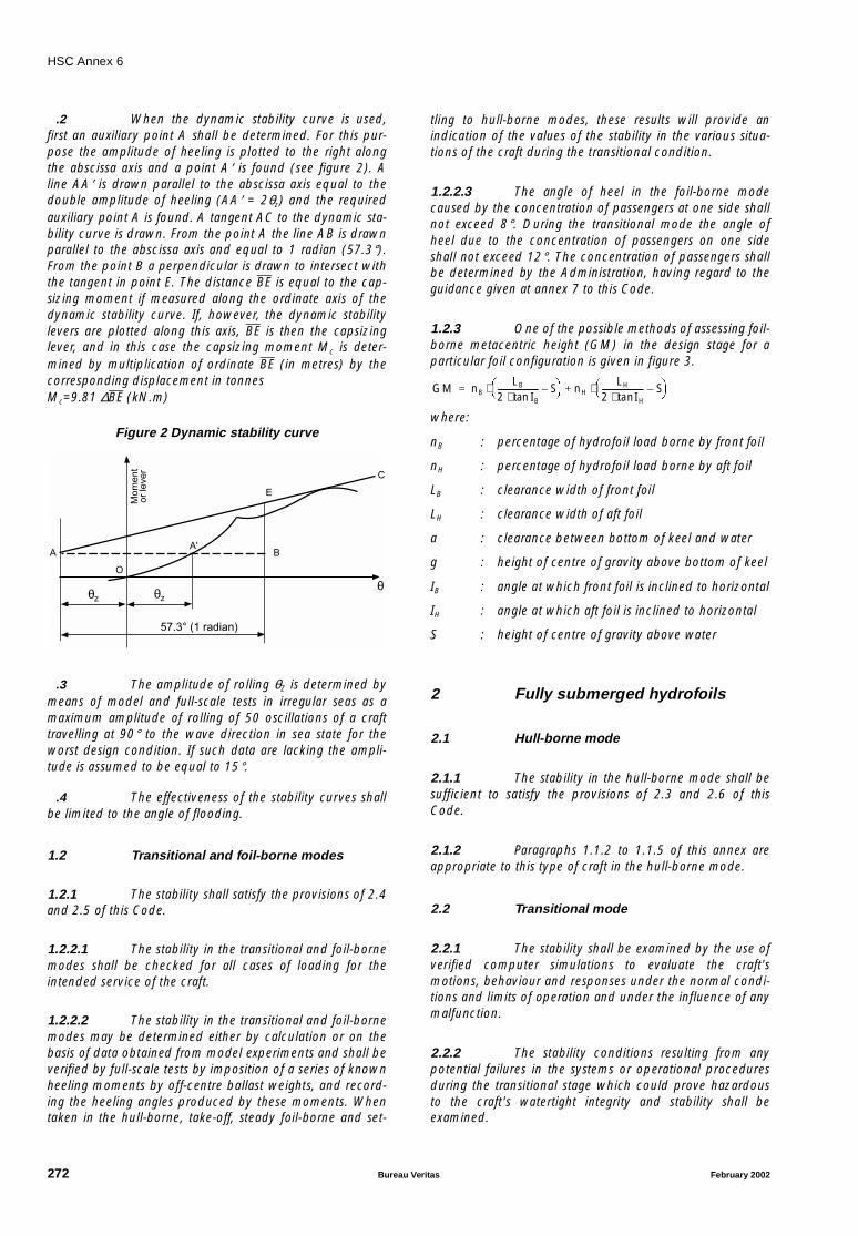
HSC Annex 6
.2 When the dynamic stability curve is used,first an auxiliary point A shall be determined. For this pur-pose the amplitude of heeling is plotted to the right alongthe abscissa axis and a point A′ is found (see figure 2). Aline AA′ is drawn parallel to the abscissa axis equal to thedouble amplitude of heeling (AA′ = 2θz) and the requiredauxiliary point A is found. A tangent AC to the dynamic sta-bility curve is drawn. From the point A the line AB is drawnparallel to the abscissa axis and equal to 1 radian (57.3°).From the point B a perpendicular is drawn to intersect withthe tangent in point E. The distance BE is equal to the cap-sizing moment if measured along the ordinate axis of thedynamic stability curve. If, however, the dynamic stabilitylevers are plotted along this axis, BE is then the capsizinglever, and in this case the capsizing moment Mc is deter-mined by multiplication of ordinate BE (in metres) by thecorresponding displacement in tonnesMc=9.81 ∆BE (kN.m)
Figure 2 Dynamic stability curve
.3 The amplitude of rolling θZ is determined bymeans of model and full-scale tests in irregular seas as amaximum amplitude of rolling of 50 oscillations of a crafttravelling at 90° to the wave direction in sea state for theworst design condition. If such data are lacking the ampli-tude is assumed to be equal to 15°.
.4 The effectiveness of the stability curves shallbe limited to the angle of flooding.
1.2 Transitional and foil-borne modes
1.2.1 The stability shall satisfy the provisions of 2.4and 2.5 of this Code.
1.2.2.1 The stability in the transitional and foil-bornemodes shall be checked for all cases of loading for theintended service of the craft.
1.2.2.2 The stability in the transitional and foil-bornemodes may be determined either by calculation or on thebasis of data obtained from model experiments and shall beverified by full-scale tests by imposition of a series of knownheeling moments by off-centre ballast weights, and record-ing the heeling angles produced by these moments. Whentaken in the hull-borne, take-off, steady foil-borne and set-
tling to hull-borne modes, these results will provide anindication of the values of the stability in the various situa-tions of the craft during the transitional condition.
1.2.2.3 The angle of heel in the foil-borne modecaused by the concentration of passengers at one side shallnot exceed 8°. During the transitional mode the angle ofheel due to the concentration of passengers on one sideshall not exceed 12°. The concentration of passengers shallbe determined by the Administration, having regard to theguidance given at annex 7 to this Code.
1.2.3 One of the possible methods of assessing foil-borne metacentric height (GM) in the design stage for aparticular foil configuration is given in figure 3.
where:
nB : percentage of hydrofoil load borne by front foil
nH : percentage of hydrofoil load borne by aft foil
LB : clearance width of front foil
LH : clearance width of aft foil
a : clearance between bottom of keel and water
g : height of centre of gravity above bottom of keel
IB : angle at which front foil is inclined to horizontal
IH : angle at which aft foil is inclined to horizontal
S : height of centre of gravity above water
2 Fully submerged hydrofoils
2.1 Hull-borne mode
2.1.1 The stability in the hull-borne mode shall besufficient to satisfy the provisions of 2.3 and 2.6 of thisCode.
2.1.2 Paragraphs 1.1.2 to 1.1.5 of this annex areappropriate to this type of craft in the hull-borne mode.
2.2 Transitional mode
2.2.1 The stability shall be examined by the use ofverified computer simulations to evaluate the craft'smotions, behaviour and responses under the normal condi-tions and limits of operation and under the influence of anymalfunction.
2.2.2 The stability conditions resulting from anypotential failures in the systems or operational proceduresduring the transitional stage which could prove hazardousto the craft's watertight integrity and stability shall beexamined.
Moment
orlever
θz
θO
θz
57.3° (1 radian)
A'A B
E
C
GM nBLB
2 IBtan⋅--------------------- S–
⋅ nH
LH
2 IHtan⋅--------------------- S–
⋅+=
272 Bureau Veritas February 2002
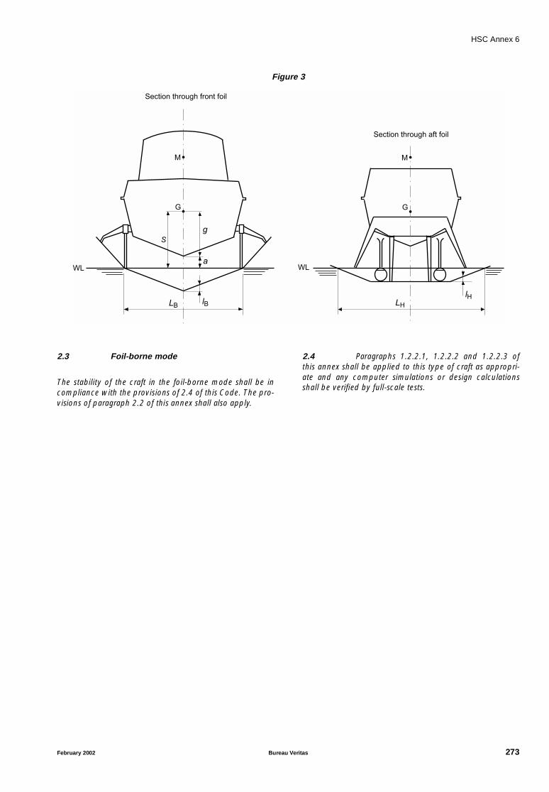
HSC Annex 6
Figure 3
2.3 Foil-borne mode
The stability of the craft in the foil-borne mode shall be incompliance with the provisions of 2.4 of this Code. The pro-visions of paragraph 2.2 of this annex shall also apply.
2.4 Paragraphs 1.2.2.1, 1.2.2.2 and 1.2.2.3 ofthis annex shall be applied to this type of craft as appropri-ate and any computer simulations or design calculationsshall be verified by full-scale tests.
WL
LB lB
a
g
S
G
M
Section through front foil
WL
LH
lH
G
M
Section through aft foil
February 2002 Bureau Veritas 273

HSC Annex 7
ANNEX 7 STABILITY OF MULTIHULL CRAFT
1 Stability criteria in the intactcondition
A multihull craft, in the intact condition, shall have sufficientstability when rolling in a seaway to successfully withstandthe effect of either passenger crowding or high-speed turn-ing as described in 1.4. The craft's stability shall beconsidered to be sufficient provided compliance with thisparagraph is achieved.
1.1 Area under the GZ curve
The area (A1) under the GZ curve up to an angle θ shall beat least:
A1 = 0.055 x 30° / θ (m.rad)
where θ is the least of the following angles:
.1 the downflooding angle;
.2 the angle at which the maximum GZ occurs;and
.3 30°
1.2 Maximum GZ
The maximum GZ value shall occur at an angle of at least10°.
1.3 Heeling due to wind
The wind heeling lever shall be assumed constant at allangles of inclination and shall be calculated as follows:
HL1 = Pi A Z / (9800 ∆) (m)
HL2 = 1.5 HL1 (m) (see figure 1)
where:
Pi = 500 (VW / 26)2 (N/m2)
where:
VW : wind speed corresponding to the worstintended conditions (m/s)
A : projected lateral area of the portion of the craftabove the lightest service waterline (m2)
Z : vertical distance from the centre of A to a pointone half the lightest service draught (m)
∆ : displacement (t).
1.4 Heeling due to passenger crowding orhigh-speed turning
Heeling due to the crowding of passengers on one side ofthe craft or to high-speed turning, whichever is the greater,shall be applied in combination with the heeling lever dueto wind (HL2).
1.4.1 Heeling due to passenger crowding
When calculating the magnitude of the heel due to passen-ger crowding, a passenger crowding lever shall bedeveloped using the assumptions stipulated in 2.10 of thisCode.
1.4.2 Heeling due to high-speed turning
When calculating the magnitude of the heel due to theeffects of high-speed turning, a high-speed turning levershall be developed using either the following formula or anequivalent method specifically developed for the type ofcraft under consideration, or trials or model test data:
where:
TL : turning lever (m)
Vo : speed of craft in the turn (m/s)
R : turning radius (m)
KG : height of vertical centre of gravity above keel(m)
d : mean draught (m)
g : acceleration due to gravity.
1.5 Rolling in waves (figure 1)
The effect of rolling in a seaway upon the craft's stabilityshall be demonstrated mathematically. In doing so, theresidual area under the GZ curve (A2), i.e. beyond the angleof heel (θh), shall be at least equal to 0.028 m.rad up to theangle of roll θr. In the absence of model test or other data θr
shall be taken as 15° or an angle of (θd − θh), whichever isless.
TL 1g---
Vo2
R------ KG d
2---–
⋅ ⋅=
274 Bureau Veritas February 2002
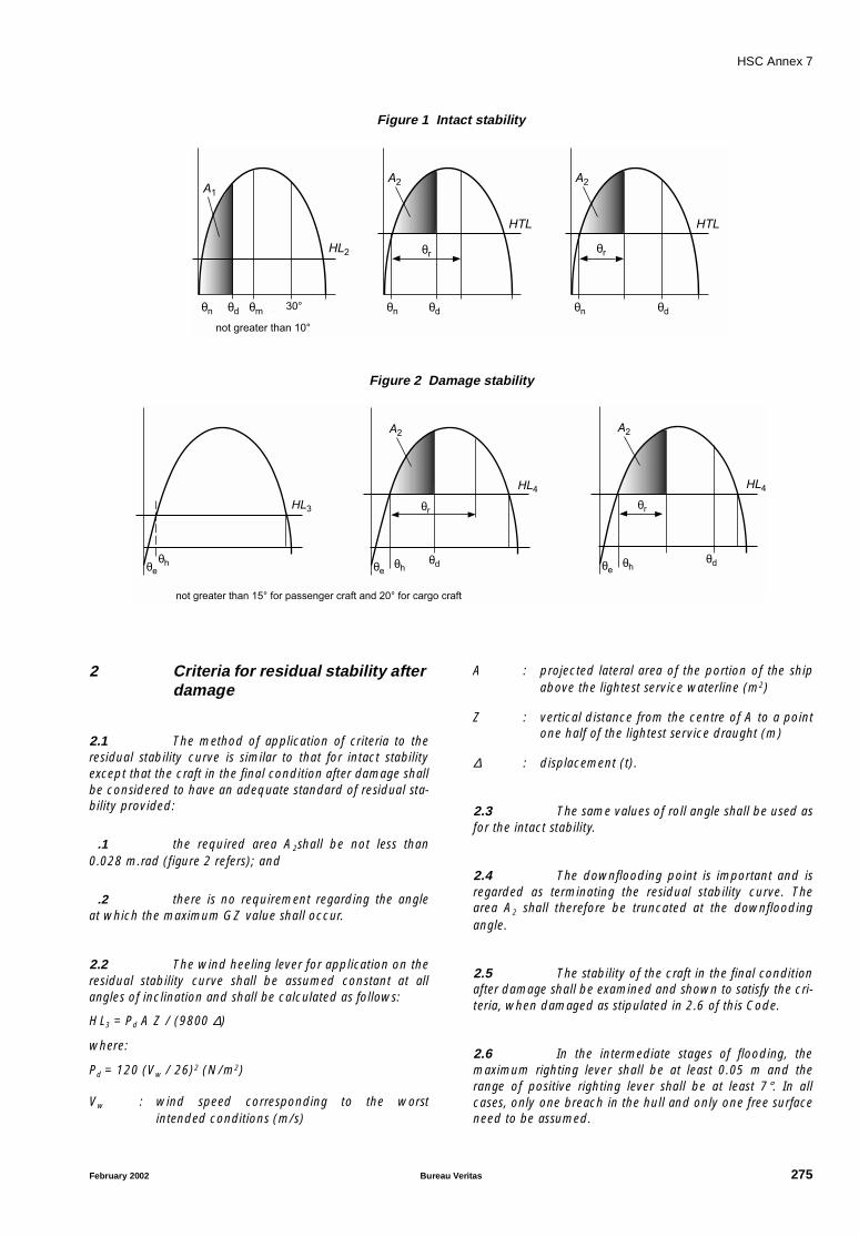
HSC Annex 7
Figure 1 Intact stability
Figure 2 Damage stability
2 Criteria for residual stability afterdamage
2.1 The method of application of criteria to theresidual stability curve is similar to that for intact stabilityexcept that the craft in the final condition after damage shallbe considered to have an adequate standard of residual sta-bility provided:
.1 the required area A2shall be not less than0.028 m.rad (figure 2 refers); and
.2 there is no requirement regarding the angleat which the maximum GZ value shall occur.
2.2 The wind heeling lever for application on theresidual stability curve shall be assumed constant at allangles of inclination and shall be calculated as follows:
HL3 = Pd A Z / (9800 ∆)
where:
Pd = 120 (Vw / 26)2 (N/m2)
Vw : wind speed corresponding to the worstintended conditions (m/s)
A : projected lateral area of the portion of the shipabove the lightest service waterline (m2)
Z : vertical distance from the centre of A to a pointone half of the lightest service draught (m)
∆ : displacement (t).
2.3 The same values of roll angle shall be used asfor the intact stability.
2.4 The downflooding point is important and isregarded as terminating the residual stability curve. Thearea A2 shall therefore be truncated at the downfloodingangle.
2.5 The stability of the craft in the final conditionafter damage shall be examined and shown to satisfy the cri-teria, when damaged as stipulated in 2.6 of this Code.
2.6 In the intermediate stages of flooding, themaximum righting lever shall be at least 0.05 m and therange of positive righting lever shall be at least 7°. In allcases, only one breach in the hull and only one free surfaceneed to be assumed.
θnnot greater than 10°
A1
HL2
HTL
θd θm 30° θn
A2
θd
θr
HTL
θn
A2
θd
θr
θh
not greater than 15° for passenger craft and 20° for cargo craft
HL3
θe θh
HL4
θe
A2
θr
θd θh
HL4
θe
A2
θr
θd
February 2002 Bureau Veritas 275
HSC Annex 7
3 Application of heeling levers
3.1 In applying the heeling levers to the intactand damaged curves, the following shall be considered:
3.1.1 for intact condition:
.1 wind heeling lever (including gusting effect)(HL2); and
.2 wind heeling lever (including gusting effect)plus either the passenger crowding or speed turning leverswhichever is the greater (HTL).
3.1.2 for damage condition:
.1 wind heeling lever–steady wind (HL3); and
.2 wind heeling lever plus heeling lever due topassenger crowding (HL4)
3.2 Angles of heel due to steady wind
3.2.1 The angle of heel due to a wind gust whenthe heeling lever HL2, obtained as in 1.3, is applied to theintact stability curve shall not exceed 10°.
3.2.2 The angle of heel due to a steady wind whenthe heeling lever HL3, obtained as in 2.2, is applied to theresidual stability curve after damage, shall not exceed 15°for passenger craft and 20° for cargo craft.
Abbreviations used in figures 1 and 2
A1 : ≥ Area required by 1.1
A2 : ≥ 0.028 m.rad.
HL2 : Heeling lever due to wind + gusting
HTL : Heeling lever due to wind + gusting + (passen-ger crowding or turning)
HL3 : Heeling lever due to wind
HL4 : Heeling lever due to wind + passenger crowd-ing
θm : Angle of maximum GZ
θd : Angle of downflooding
θr : Angle of roll
θe : Angle of equilibrium, assuming no wind, pas-senger crowding or turning effects
θh : Angle of heel due to heeling lever HL2, HTL, HL3
or HL4
276 Bureau Veritas February 2002
HSC Annex 8
ANNEX 8 STABILITY OF MONOHULL CRAFT
1 Stability criteria in the intactcondition
1.1 The weather criterion contained in para-graph 3.2 of the Intact Stability Code shall apply (see note).In applying the weather criterion the value of wind pressureP (N/m2) shall be taken as (500Vw / 262), where Vw =wind speed (m/s) corresponding to the worst intended con-ditions. In applying the weather criterion account shall alsobe taken of the roll damping characteristics of individualcraft in assessing the assumed roll angle Θ1, which mayalternatively be derived from model or full-scale tests. Hullswith features which greatly increase damping, such asimmersed sidehulls, substantial arrays of foils, or flexibleskirts or seals, are likely to experience significantly smallermagnitudes of roll angle. For such craft, therefore, the rollangle shall be derived from model or full-scale tests or in theabsence of such data shall be taken as 15°.
Note: Refer to the Code on Intact stability for all types of ships cov-ered by IMO instruments, adopted by the Organization byresolution A.749(18), as amended by resolution MSC.75(69).
1.2 The area under the righting lever curve (GZcurve) shall not be less than 0.07 m.rad up to Θ = 15° whenthe maximum righting lever (GZ) occurs at Θ = 15°, and0.055 m.rad up to Θ = 30° when the maximum righting le-ver occurs at Θ = 30° or above. Where the maximum right-ing lever occurs at angles of between Θ = 15° and Θ = 30°,the corresponding area under the righting lever curve shallbe:
A = 0.055 + 0.001 (30° − Θmax) (m.rad)
where:
Θmax : is the angle of heel, in degrees, at which therighting lever curve reaches its maximum.
1.3 The area under the righting lever curvebetween Θ = 30° and Θ = 40° or between Θ = 30° and theangle of flooding ΘF if this angle is less than 40°, shall not beless than 0.03 m.rad.
Note: In applying this criterion, small openings through which pro-gressive flooding cannot take place need not be considered asopen.
1.4 The righting lever GZ shall be at least 0.2 mat an angle of heel equal to or greater than 30°.
1.5 The maximum righting lever shall occur at anangle of heel not less than 15°.
1.6 The initial metacentric height GMT shall notbe less than 0.15 m.
2 Criteria for residual stability afterdamage
2.1 The stability required in the final conditionafter damage, and after equalization where provided, shallbe determined as specified in 2.1.1 to 2.1.4.
2.1.1 The positive residual righting lever curveshall have a minimum range of 15° beyond the angle ofequilibrium. This range may be reduced to a minimum of10°, in the case where the area under the righting levercurve is that specified in 2.1.2, increased by the ratio:15 / rangewhere the range is expressed in degrees.
2.1.2 The area under the righting lever curve shallbe at least 0.015 m.rad, measured from the angle of equilib-rium to the lesser of:
.1 the angle at which progressive floodingoccurs; and
.2 27° measured from the upright.
2.1.3 A residual righting lever shall be obtainedwithin the range of positive stability, taking into account thegreatest of the following heeling moments:
.1 the crowding of all passengers towards oneside;
.2 the launching of all fully loaded davit-launched survival craft on one side; and
.3 due to wind pressure,
as calculated by the formula:GZ = heeling moment / (displacement) + 0.04 (m)However, in no case, this righting lever shall be less than 0.1m.
2.1.4 For the purpose of calculating the heelingmoments referred to in 2.1.3, the following assumptionsshall be made:
.1 Moments due to crowding of passengers.This should be calculated in accordance with paragraph2.10 of the Code.
February 2002 Bureau Veritas 277

HSC Annex 8
.2 Moments due to launching of all fully loadeddavit-launched survival craft on one side:
.2.1 all lifeboats and rescue boats fitted on the sideto which the ship has heeled after having sus-tained damage shall be assumed to be swungout fully loaded and ready for lowering;
.2.2 for lifeboats which are arranged to be launchedfully loaded from the stowed position, the maxi-mum heeling moment during launching shall betaken;
.2.3 a fully loaded davit-launched liferaft attached toeach davit on the side to which the ship hasheeled after having sustained damage shall beassumed to be swung out ready for lowering;
.2.4 persons not in the life-saving appliances whichare swung out shall not provide either additionalheeling or righting moment; and
.2.5 life-saving appliances on the side of the shipopposite to the side to which the ship hasheeled shall be assumed to be in a stowedposition.
.3 Moments due to wind pressure:
.3.1 the wind pressure shall be taken as
(120 Vw / 262) (N/m2), where Vw = wind
speed (m/s), corresponding to the worstintended condition;
.3.2 the area applicable shall be the projected lateralarea of the ship above the waterline corre-sponding to the intact condition; and
.3.3 the moment arm shall be the vertical distancefrom a point at one half of the mean draughtcorresponding to the intact condition to thecentre of gravity of the lateral area.
2.2 In intermediate stages of flooding, the maxi-mum righting lever shall be at least 0.05 m and the range ofpositive righting levers shall be at least 7°. In all cases, onlyone breach in the hull and only one free surface need beassumed.
278 Bureau Veritas February 2002
HSC Annex 9
ANNEX 9 DEFINITIONS, REQUIREMENTS AND COMPLIANCE
CRITERIA RELATED TO OPERATIONAL AND SAFETY
PERFORMANCE
This annex applies to all types of craft. Tests to evaluateoperational safety shall be conducted on the prototype craftof a new design or of a design incorporating new featureswhich may modify the results of a previous testing. The testsshall be carried out to a schedule agreed between theAdministration and the manufacturer. Where conditions ofservice warrant additional testing (e.g., low temperature),the Administration or base port State authorities as appro-priate may require further demonstrations. Functionaldescriptions, technical and system specifications relevant tothe understanding and evaluation of craft performance shallbe available.
The objective of these tests is to provide essential informa-tion and guidance to enable the craft to be operated safelyunder normal and emergency conditions within the designspeed and environmental envelope.
C0 Tests required by the Administration in pursuanceof annex 9 are to be carried out in the presence of the Soci-ety Surveyor.
The following procedures are outlined as requirements indealing with verification of craft performance.
1 Performance
1.1 General
1.1.1 The craft shall meet the applicable opera-tional requirements in chapter 17 of this Code and thisannex for all extremes of passenger and load configurationsfor which certification is required. The limiting sea staterelated to the different modes of operation shall be verifiedby tests and analyses of a craft of the type for which certifi-cation is requested.
1.1.2 Operational control of the craft shall be inaccordance with procedures established by the applicantfor operation in service. Procedures to be established shallbe start procedure, cruise procedures, normal and emer-gency stop and manoeuvre procedures.
1.1.3 The procedures established under 1.1.2shall:
.1 demonstrate that normal manoeuvres andcraft responses to failures are consistent in performance;
.2 use methods or devices that are safe and reli-able; and
.3 include allowance for any time lag in the exe-cution of procedures that may reasonably be expected inservice.
1.1.4 Procedures required by this annex shall beconducted over water of sufficient depth such that craft per-formance will not be affected.
1.1.5 Tests shall be conducted at minimum practi-cable weight and additional testing shall be conducted atmaximum weight sufficient to establish the need for addi-tional restrictions and for testing to examine the effect ofweight.
2 Stopping
2.1 This test is to establish the acceleration expe-rienced when stopping the craft in calm water with nopassenger load or cargo load during the followingconditions:
.1 normal stop for maximum operational speed;
.2 emergency stop for maximum operationalspeed; and
.3 crash stop from maximum operational speedand from any transitional mode speed.
2.2 The tests referred to in 2.1.1 and 2.1.2 shalldocument that the accelerations do not exceed safety level1 in annex 3 when control levers are used in accordance towritten procedures as given in the craft operating manual orin an automatic mode. Should safety level 1 be exceededduring normal stop, control systems shall be modified inorder to avoid exceedance or passengers shall be requiredto be seated during normal stop. Should safety level 1 beexceeded during emergency stop, then written proceduresin the craft operating manual shall include detailed informa-tion of how to avoid exceedance or the control system shallbe modified to avoid exceedance.
February 2002 Bureau Veritas 279
HSC Annex 9
2.3 The test referred to in 2.1.3 shall documentthat the accelerations do not exceed safety level 2 in annex3 when control levers of automatic modes are used in amanner which will give the highest accelerations. If safetylevel 2 is exceeded then the craft operating manual shallinclude a warning that it is a risk to passengers beinginjured, if a crash stop is performed.
2.4 Other tests shall be repeated during craftturning to establish the need or otherwise to impose anyspeed-related restrictions during manoeuvres.
3 Cruise performance
3.1 This test is to establish the craft performanceand accelerations experienced during cruise modes with nopassenger load or cargo load during the followingconditions:
.1 normal operation conditions are those inwhich the craft will safely cruise at any heading while manu-ally operated, auto-pilot assisted operated or operated withany automatic control system in normal mode; and
.2 worst intended conditions, referred to in1.4.57 of this Code, are those in which it shall be possible tomaintain safe cruise without exceptional piloting skill. How-ever, operations at all headings relative to the wind and seamay not be possible. For type of craft having a higher per-formance standard in non-displacement mode, theperformance and accelerations shall also be established atdisplacement mode during operation in the worst intendedcondition.
3.2 Operation levels, as defined in 3.1, shall beestablished and documented by full-scale tests in at leasttwo relevant sea conditions and in head, beam and follow-ing seas. It shall be shown that the period of every test (run)and the number of series are sufficient for achieving reliablemeasurements. In every sea state tested, the aggregate timein each direction shall not be less than 15 min. Model testsand mathematical simulations could be used to verify theperformance in the worst intended conditions.
Limits for normal operation condition shall be documentedby measurements of craft speed, heading to the wave andinterpolation of measurements of maximum horizontalaccelerations in accordance with 2.4 of annex 3. Measure-ment of wave height and period shall be made to themaximum extent practicable.
Limits for worst intended condition shall be documented bymeasurements of craft speed, wave height and period,heading to the wave and by root mean square (RMS) valuesof horizontal accelerations in accordance with 2.4 of annex3 and of vertical accelerations close to the craft longitudinalcentre of gravity. RMS values could be used for extrapola-tion of peak values. To obtain the expected peak values
related to structural design load and safety levels (one per5-min exceedance), multiply the RMS values by 3.0 or
where:
N : is the number of successive amplitudes withinthe relevant period.
If not otherwise verified by model tests or by mathematicalcalculations, it might be assumed a linear relation betweenwave height and accelerations based on measurements inthe two sea conditions. Limits for worst intended conditionshall be documented both related to passenger safety inaccordance with 2.4 of annex 3 and related to the actualstructural design load of the craft.
3.3 The tests and verification process shall docu-ment the limiting seas for safe operation of the craft:
.1 in normal operation at maximum operationalspeed the accelerations shall not exceed safety level 1 inannex 3 with an average of one per 5-min period. The craftoperating manual shall include detailed description of theeffects of speed reduction or change of heading to thewaves in order to prevent exceedance;
.2 in the worst intended conditions, withreduced speed as necessary, the accelerations shall notexceed safety level 2 in annex 3 with an average of one per5-min period, nor shall any other craft characteristic motionas pitch, roll and yaw exceed levels that could impede thesafety of passengers. In worst intended conditions, withreduced speed as necessary, craft shall be safely manoeu-vrable and provide adequate stability in order that the craftcan continue safe operation to the nearest place of refuge,provided caution is exercised in handling. Passengers shallbe required to be seated when safety level 1 in annex 3 isexceeded; and
.3 within the actual structural design load forthe craft, with reduced speed and change of heading, asnecessary.
3.4 Turning and manoeuvrability
The craft shall be safely controllable and manoeuvrableduring:
.1 hull-borne operation;
.2 operation in non-displacement mode;
.3 take-off, landing;
.4 any intermediate or transition modes, asapplicable; and
.5 berthing operations, as applicable.
C 2 Nln⋅=
280 Bureau Veritas February 2002

HSC Annex 9
4 Effects of failures or malfunction
4.1 General
The limits of safe operation, special handling proceduresand any operational restrictions shall be examined anddeveloped as a result of full-scale trials conducted by simu-lating possible equipment failures.The failures to be examined shall be those leading to majoror more severe effects as determined from evaluation ofFMEA or similar analysis.Failures to be examined shall be agreed between the craftmanufacturer and the Administration and each single failureshall be examined in a progressive manner.
4.2 Objects of tests
Examination of each failure shall result in:
.1 determining safe limits of craft operation atthe time of failure, beyond which the failure will result indegradation beyond safety level 2;
.2 determining crew member's actions, if any,to minimize or counter the effect of the failure; and
.3 determining craft or machinery restrictions tobe observed to enable the craft to proceed to a place of ref-uge with the failure present.
4.3 Failures to be examined
Equipment failures shall include, but not be limited to, thefollowing:
.1 total loss of propulsion power;
.2 total loss of lift power (for ACV and SES);
.3 total failure of control of one propulsionsystem;
.4 involuntary application of full propulsionthrust (positive or negative) on one system;
.5 failure of control of one directional controlsystem;
.6 involuntary full deflection of one directionalcontrol system;
.7 failure of control of trim control system;
.8 involuntary full deflection of one trim controlsystem element; and
.9 total loss of electrical power.
Failures shall be fully representative of service conditionsand shall be simulated as accurately as possible in the mostcritical craft manoeuvre where the failure will have maxi-mum impact.
4.4 “Dead ship” test
In order to establish craft motions and direction of laying towind and waves, for the purposes of determining the condi-tions of a craft evacuation, the craft shall be stopped and allmain machinery shut down for sufficient time that the craft'sheading relative to wind and waves has stabilized. This testshall be carried out on an opportunity basis to establish pat-terns of the design's “dead ship” behaviour under a varietyof wind and sea states.
February 2002 Bureau Veritas 281

HSC Annex 10
ANNEX 10 CRITERIA FOR TESTING AND EVALUATION OF
REVENUE AND CREW SEATS
1 Purpose and scope
The purpose of these criteria is to provide requirements forrevenue and crew seats, seat anchorage and seat accesso-ries and their installation to minimize occupant injuryand/or disruption of egress/ingress if the craft suffers acollision.
2 Static seat tests
2.1 The requirements of this section are applica-ble to all crew and revenue seats.
2.2 All seats to which this paragraph applies,along with their supports and deck attachments, shall bedesigned to withstand at least the following static forcesapplied in the direction of the craft:
.1 Forward direction: a force of 2.25 kN,
.2 After direction: a force of 1.5 kN,
.3 Transverse direction: a force of 1.5 kN,
.4 Vertically downward: a force of 2.25 kN, and
.5 Vertically upward: a force of 1.5 kN.A seat shall comprise a frame, bottom and back. Forcesapplied in the fore or aft direction of the seat shall beapplied horizontally to the seat back 350 mm above theseat bottom. Forces applied in the transverse seat directionshall be applied horizontally to the seat bottom. Verticalupward forces shall be evenly distributed to the corners ofthe seat bottom frame. Vertical downward forces shall beuniformly distributed over the seat bottom.If a seating unit consists of more than one seating position,these forces shall be applied at each seating position con-currently during the tests.
2.3 When the forces are applied to a seat, con-sideration shall be given to the direction in which the seat isto face in the craft. For example, if the seat faces sideways,the transverse craft force would be applied fore and aft onthe seat and the forward craft force would be applied trans-versely on the seat.
2.4 Each seating unit to be tested shall beattached to the support structure similar to the manner inwhich it will be attached to the deck structure in the craft.
Although a rigid support structure can be used for thesetests, a support structure, having the same strength and stiff-ness as the support structure in the craft, is preferred.
2.5 The forces described in 2.2.1 to 2.2.3 shallbe applied to the seat through a cylindrical surface having aradius of 80 mm and a width at least equal to the width ofthe seat. The surface shall be equipped with at least oneforce transducer able to measure the forces applied.
2.6 The seat shall be considered acceptable if:
.1 under the influence of the forces referred toin 2.2.1 to 2.2.3, the permanent displacement measured atthe point of application of the force is not more than 400mm;
.2 no part of the seat, the seat mountings or theaccessories become completely detached during the tests;
.3 the seat remains firmly held, even if one ormore of the anchorages is partly detached;
.4 all of the locking systems remain locked dur-ing the entire test but the adjustment and locking systemsneed not be operational after the tests; and
.5 rigid parts of the seat with which the occu-pant may come into contact shall present a curved surfacewith a radius of at least 5 mm.
2.7 The requirements of section 3 may be usedin lieu of the requirements of this section provided that theaccelerations used for the tests are at least 3 g.
3 Dynamic seat tests
3.1 The requirements of this section are applica-ble in addition to those in 2.1 for crew and revenue seats incraft having a design collision load of 3 g or greater.
3.2 All seats for which this section applies, theseat supporting structure, the attachment to the deck struc-ture, the lap belt, if installed, and shoulder harness, ifinstalled, shall be designed to withstand the maximumacceleration force that can be imposed upon them during adesign collision. Consideration shall be given to the orienta-tion of the seat relative to the acceleration force (i.e.whether the seat is forward-, aft-, or side-facing).
282 Bureau Veritas February 2002

HSC Annex 10
3.3 The acceleration pulse to which the seat issubjected shall be representative of the collision time-his-tory of the craft. If the collision time-history is not known, orcannot be simulated, the acceleration time-history envelopeshown in the figure can be used.
3.4 In the test frame, each seat unit and its acces-sories (e.g., lap belts and shoulder harnesses) shall beattached to the support structure similar to the manner inwhich it will be attached in the craft. The support structurecan be a rigid surface; however, a support structure havingthe same strength and stiffness as the support structure inthe craft is preferred. Other seats and/or tables with whichan occupant may come in contact during a collision shall beincluded in the test frame in an orientation and with amethod of attachment typical of that in the craft.
Figure 1 Acceleration time-history envelope
3.5 During the dynamic seat test, a fiftieth per-centile anthropomorphic test dummy, suitable for the testbeing conducted, shall be placed in the seat in an uprightseating position. If a typical seating unit is composed ofmore than one occupant seat, a test dummy shall be placedin each occupant seat in the unit. The dummy, or dummies,shall be secured in the seat unit in accordance with proce-dures of recognized national standards (see note) and besecured using only the lap belt and shoulder harness if theyare installed. Tray tables and other such devices shall beplaced in the position that would cause the greatest poten-tial for an occupant to become injured.
Note: Refer to ECE 80 with addendum 79. Other national stand-ards may be acceptable.
3.6 The test dummy shall be instrumented andcalibrated, in accordance with the requirements of a recog-nized national standard, so as to permit, as a minimum,calculation of the head injury criterion, calculation of thethoracic trauma index, measurement of force in the femur,and measurement, if possible, of extension and flexion ofthe neck.
3.7 If more than one dummy is used in the tests,the dummy located in the seat having the highest potential
for an occupant to be injured shall be the one instrumented.The other dummy or dummies need not be instrumented.
3.8 The tests shall be conducted and the instru-mentation shall be sampled at a rate sufficient to reliablyshow response of the dummy in accordance with therequirements of a recognized national standard.
Note: Refer to the specifications of International Standard ISO6487–Technique of measurement in impact tests (1987) or SAEJ211–Instrumentation.
3.9 The seat unit tested in accordance with therequirements of this section shall be considered acceptableif:
.1 the seat unit and tables installed in the seatunit or area do not become dislodged from the supportingdeck structure and do not deform in a manner that wouldcause the occupant to become trapped or injured;
.2 the lap belt, if installed, remains attachedand on the test dummy's pelvis during the impact. Theshoulder harness, if installed, remains attached and in theimmediate vicinity of the test dummy's shoulder during theimpact. After the impact, the release mechanisms of anyinstalled lap belt and shoulder harness shall be operative;
.3 the following acceptability criteria are met:
.3.1 the head injury criterion (HIC), calculated inaccordance with the formula, does not exceed500
where:t1 and t2 are the beginning and ending times (inseconds) of the interval in which the HIC is amaximum. The term a(t) is the resultant meas-ured acceleration in the head of the dummy ing;
.3.2 the thoracic trauma index (TTI), calculated inaccordance with the formula, does not exceed30 g except for periods totalling less than 3 msTTI = (gR + gLS) / 2 or acceleration at the centreof gravitywhere:
gR : is the acceleration in g of either theupper or lower rib;
gLS : is the acceleration in g of the lowerspine; and
.3.3 the force in the femur does not exceed 10 kNexcept that it cannot exceed 8 kN for periodstotalling more than 20 ms; and
.4 loads on the upper torso harness straps donot exceed 7.8 kN or a total of 8.9 kN if dual straps areused.
1.0
10
0.7
20 70
g/gcoll
80 90 150 Time (ms)
HIC t2 t1–( ) 1t2 t1–------------- a t( ) td
t1
t2
2,5
=
February 2002 Bureau Veritas 283

HSC Annex 11
284
ANNEX 11 OPEN REVERSIBLE LIFERAFTS
1 General
1.1 All open reversible liferafts shall:
.1 be constructed with proper workmanshipand materials;
.2 not be damaged in stowage throughout theair temperature range of -18° C to +65° C;
.3 be capable of operating throughout an airtemperature range of −18° C to +65° C and a seawater tem-perature range of −1° C to +30° C;
.4 be rot-proof, corrosion-resistant and not beunduly affected by seawater, oil or fungal attack;
.5 be stable and maintain their shape wheninflated and fully laden; and
.6 be fitted with retro-reflective material, whereit will assist in detection, and in accordance with the recom-mendations adopted by the Organization.
Note: Refer to the Recommendation on the Use and Fitting ofRetro-Reflective Materials on Life-Saving Appliances, adopted bythe Organization by resolution A.658(16).
2 Construction
2.1 The open reversible liferaft shall be so con-structed that when it is dropped into the water in itscontainer from a height of 10 m, the liferaft and its equip-ment will operate satisfactorily. If the open reversible liferaftis to be stowed at a height of more than 10 m above thewaterline in the lightest seagoing condition, it shall be of atype which has been satisfactorily drop-tested from at leastthat height.
2.2 The open reversible floating liferaft shall becapable of withstanding repeated jumps on to it from aheight of at least 4.5 m.
2.3 The open reversible liferaft and its fittingsshall be so constructed as to enable it to be towed at aspeed of 3 knots in calm water when loaded with its fullcomplement of persons and equipment, with the sea-anchor deployed.
2.4 The open reversible liferaft when fullyinflated shall be capable of being boarded from the waterwhichever way up it inflates.
2.5 The main buoyancy chamber shall bedivided into:
.1 not less than two separate compartments,each inflated through a nonreturn inflation valve on eachcompartment; and
.2 the buoyancy chambers shall be so arrangedthat in the event of one of the compartments being dam-aged or failing to inflate, the intact compartment shall beable to support, with positive freeboard over the openreversible liferaft's entire periphery, the number of personswhich the liferaft is permitted to accommodate, each havinga mass of 75 kg and seated in their normal positions.
2.6 The floor of the open reversible liferaft shallbe waterproof.
2.7 The open reversible liferaft shall be inflatedwith a non-toxic gas by an inflation system complying withthe requirements of paragraph 4.2.2 of the LSA Code. Infla-tion shall be completed within the period of one minute atan ambient temperature of between 18° C and 20° C andwithin a period of three minutes at an ambient temperatureof −18° C. After inflation the open reversible liferaft shallmaintain its form when loaded with its full complement ofpersons and equipment.
2.8 Each inflatable compartment shall be capa-ble of withstanding a pressure equal to at least three timesthe working pressure and shall be prevented from reachinga pressure exceeding twice the working pressure either bymeans of relief valves or by a limited gas supply. Meansshall be provided for fitting the topping-up pump orbellows.
2.9 The surface of the buoyancy tubes shall be ofnon-slip material. At least 25% of these tubes shall be of ahighly visible colour.
2.10 The number of persons which an openreversible liferaft shall be permitted to accommodate shallbe equal to the lesser of:
.1 the greatest whole number obtained bydividing by 0.096 the volume, measured in cubic metres, ofthe main buoyancy tubes (which for this purpose shall notinclude the thwarts, if fitted) when inflated; or
Bureau Veritas February 2002
HSC Annex 11
.2 the greatest whole number obtained bydividing by 0.372 the inner horizontal cross-sectional areaof the open reversible liferaft measured in square metres(which for this purpose may include the thwart or thwarts, iffitted) measured to the innermost edge of the buoyancytubes; or
.3 the number of persons having an averagemass of 75 kg, all wearing lifejackets, that can be seatedinboard of the buoyancy tubes without interfering with theoperation of any of the liferaft's equipment.
3 Open reversible liferaft fittings
3.1 Lifelines shall be securely becketed aroundthe inside and outside of the open reversible liferaft.
3.2 The open reversible liferaft shall be fittedwith an efficient painter of a length suitable for automaticinflation on reaching the water. For open reversible liferaftsaccommodating more than 30 persons an additional bows-ing-in line shall be fitted.
3.3 The breaking strength of the painter system,including its means of attachment to the open reversible lif-eraft, except the weak link required by paragraph 4.1.6.2 ofthe LSA Code, shall be:
.1 7.5 kN for open reversible liferafts accommo-dating up to 8 persons;
.2 10.0 kN for open reversible liferafts accom-modating 9 to 30 persons; and
.3 15.0 kN for open reversible liferafts accom-modating more than 30 persons.
3.4 The open reversible liferaft shall be fittedwith at least the following number of inflated ramps to assistboarding from the sea whichever way up the raft inflates:
.1 one boarding ramp for open reversible lifer-afts accommodating up to 30 persons; or
.2 two boarding ramps for open reversible lifer-afts accommodating more than 30 persons; such boardingramps shall be 180° apart.
3.5 The open reversible liferaft shall be fittedwith water pockets complying with the followingrequirements:
.1 the cross-sectional area of the pockets shallbe in the shape of an isosceles triangle with the base of thetriangle attached to the buoyancy tubes of the open reversi-ble liferaft;
.2 the design shall be such that the pockets fillto approximately 60% of capacity within 15 s to 25 s ofdeployment;
.3 the pockets attached to each buoyancy tubeshall normally have aggregate capacity of between 125 land 150 l for inflatable open reversible liferafts up to andincluding the 10-person size;
.4 the pockets to be fitted to each buoyancytube on liferafts certified to carry more than 10 persons shallhave, as far as practicable, an aggregate capacity of12 N litres, where N is the number of persons carried;
.5 each pocket on a buoyancy tube shall beattached so that when the pocket is in the deployed posi-tion it is attached along the full length of its upper edges to,or close to, the lowest part of the lower buoyancy tube; and
.6 the pockets shall be distributed symmetri-cally round the circumference of the liferaft with sufficientseparation between each pocket to enable air to escapereadily.
3.6 At least one manually controlled lamp com-plying with the requirements shall be fitted on the upperand lower surfaces of the buoyancy tubes.
3.7 Suitable automatic drain arrangements shallbe provided on each side of the floor of the liferaft in the fol-lowing manner:
.1 one for open reversible liferafts accommodat-ing up to 30 persons; or
.2 two for open reversible liferafts accommo-dating more than 30 persons.
3.8 The equipment of every open reversible lifer-aft shall consist of:
.1 one buoyant rescue quoit, attached to notless than 30 m of buoyant line with a breaking strength of atleast 1 kN;
.2 two safety knives of the non-folding type,having a buoyant handle, shall be fitted attached to openreversible liferaft by light lines. They shall be stowed inpockets so that, irrespective of the way in which the openreversible liferaft inflates, one will be readily available on thetop surface of the upper buoyancy tube in a suitable posi-tion to enable the painter to be readily cut;
.3 one buoyant bailer;
.4 two sponges;
.5 one sea-anchor permanently attached to theopen reversible liferaft in such a way as to be readilydeployable when the open reversible liferaft inflates. Theposition of the sea-anchor shall be clearly marked on bothbuoyancy tubes;
February 2002 Bureau Veritas 285
HSC Annex 11
.6 two buoyant paddles;
.7 one first-aid outfit in a waterproof case capa-ble of being closed tightly after use;
.8 one whistle or equivalent sound signal;
.9 two hand flares;
.10 one waterproof electric torch suitable forMorse signalling together with one spare set of batteries andone spare bulb in a waterproof container;
.11 one repair outfit for repairing punctures inbuoyancy compartments; and
.12 one topping-up pump or bellows.
3.9 The equipment specified in 3.8 is designatedan HSC Pack.
3.10 Where appropriate, the equipment shall bestowed in a container which, if it is not an integral part of, orpermanently attached to, the open reversible liferaft, shallbe stowed and secured to the open reversible liferaft and becapable of floating in water for at least 30 min without dam-age to its contents. Irrespective of whether the equipmentcontainer is an integral part of, or is permanently attachedto, the open reversible liferaft, the equipment shall be read-ily accessible irrespective of which way up the openreversible liferaft inflates. The line which secures the equip-ment container to the open reversible liferaft shall have abreaking strength of 2 kN or a breaking strength of 3:1based on the mass of the complete equipment pack, which-ever is the greater.
4 Containers for open reversibleinflatable liferafts
4.1 The open reversible liferafts shall be packedin a container that is:
.1 so constructed as to withstand conditionsencountered at sea;
.2 of sufficient inherent buoyancy, whenpacked with the liferaft and its equipment, to pull thepainter from within and to operate the inflation mechanismshall the craft sink; and
.3 as far as practicable, watertight, except fordrain holes in the container bottom.
4.2 The container shall be marked with:
.1 maker's name or trademark;
.2 serial number;
.3 the number of persons it is permitted tocarry;
.4 non-SOLAS reversible;
.5 type of emergency pack enclosed;
.6 date when last serviced;
.7 length of painter;
.8 maximum permitted height of stowage abovewaterline (depending on drop-test height); and
.9 launching instructions.
5 Markings on open reversibleinflatable liferafts
The open reversible liferafts shall be marked with:
.1 maker's name or trademark;
.2 serial number;
.3 date of manufacture (month and year);
.4 name and place of service station where itwas last serviced; and
.5 number of persons it is permitted to accom-modate on the top of each buoyancy tube, in characters notless than 100 mm in height and of a colour contrasting withthat of the tube.
6 Instructions and information
Instructions and information required for inclusion in thecraft's training manual and in the instructions for on-boardmaintenance shall be in a form suitable for inclusion in suchtraining manual and instructions for on-board maintenance.Instructions and information shall be in a clear and conciseform and shall include, as appropriate, the following:
.1 general description of the open reversible lif-eraft and its equipment;
.2 installation arrangements;
.3 operational instructions, including use ofassociated survival equipment; and
.4 servicing requirements.
286 Bureau Veritas February 2002

HSC Annex 11
7 Testing of open reversibleinflatable liferafts
7.1 When testing open reversible liferafts inaccordance with the recommendations of resolutionMSC.81(70), part 1:
.1 tests No. 5.5, 5.12, 5.16, 5.17.2, 5.17.10,5.17.11, 5.17.12, 5.18 and 5.20 may be omitted;
.2 the part of test No. 5.8 regarding closingarrangement may be omitted,
.3 the temperature -30° C in test No. 5.17.3and 5.17.5 may be substituted with -18° C; and
.4 the drop height of 18 m in test No. 5.1.2 maybe substituted with 10 m.
Omittances and substitution, as described above, shall bereflected in the type approval certificate.
February 2002 Bureau Veritas 287

HSC Annex 11
288 Bureau Veritas February 2002