Rui Miguel Mecanismos de Ofoading para Redes Móveis usando ...
130
Universidade de Aveiro Departamento de Eletrónica, Telecomunicações e Informática 2018 Rui Miguel Morais da Silva Mecanismos de Offloading para Redes Móveis usando SDN em Ambientes Virtualizados Offloading Mechanisms for Mobile Networks using SDN in Virtualized Environments
Transcript of Rui Miguel Mecanismos de Ofoading para Redes Móveis usando ...

Universidade de AveiroDepartamento de Eletrónica,Telecomunicações e Informática
2018
Rui MiguelMorais da Silva
Mecanismos de Offloading para Redes Móveisusando SDN em Ambientes Virtualizados
Offloading Mechanisms for Mobile Networks usingSDN in Virtualized Environments


Universidade de AveiroDepartamento de Eletrónica,Telecomunicações e Informática
2018
Rui MiguelMorais da Silva
Mecanismos de Offloading para Redes Móveisusando SDN em Ambientes Virtualizados
Offloading Mechanisms for Mobile Networks usingSDN in Virtualized Environments
Dissertação apresentada à Universidade de Aveiro para cumprimento dosrequisitos necessários à obtenção do grau de Mestre em EngenhariaEletrónica e Telecomunicações, realizada sob a orientação científica doDoutor Daniel Nunes Corujo, investigador doutorado do Departamento deEletrónica, Telecomunicações e Informática da Universidade de Aveiro, e doDoutor Rui Luís Andrade Aguiar, Professor catedrático do Departamento deEletrónica, Telecomunicações e Informática da Universidade de Aveiro.


o júri / the jury
presidente / president Prof. Doutor João Paulo Silva Barracaprofessor auxiliar do Departamento de Eletrónica, Telecomunicações e Informática da Universi-
dade de Aveiro
vogais / examiners committee Doutor Sérgio Miguel Calafate de Figueiredoconsultor/engenheiro sénior na Altran Portugal
Doutor Daniel Nunes Corujoinvestigador doutorado do Departamento de Eletrónica, Telecomunicações e Informática da Uni-
versidade de Aveiro


agradecimentos /acknowledgements
Agradeço ao Doutor Daniel Corujo e ao Professor Doutor Rui Aguiar por todaa orientação.Agradeço à minha namorada pelo apoio incondicional.Agradeço aos meus pais pelo apoio financeiro e ao meu irmão e aos meusamigos pelos momentos de descontração.Esta dissertação de mestrado foi realizada com o apoio do Instituto de Tele-comunicações em Aveiro.


Palavras Chave 5G, 4G, SDN, NFV, Cloud, Virtualização, Offloading, EPC
Resumo O explosivo aumento do tráfego móvel em anos recentes tem vindo a aumen-tar a carga nas células e núcleo da rede móvel, com os operadores a seremconfrontados com a necessidade de atualizar as mesmas. Hoje em dia, paraexecutar esta atualização, os operadores necessitam de adquirir equipamentonovo e especializado para as funções de rede, levando a um grande CAPEXde atualização. Além disso, as redes são implementadas seguindo uma abor-dagem de uma solução única para todos os casos, o que nalguns pode nãosatisfazer os requisitos de serviços específicos. O 5G visa resolver estesproblemas ao virtualizar funções de rede em datacenters, desacoplando osoftware do hardware para as funções de rede e ao utilizar hardware de usogeral. Para suportar isto, as redes definidas por software (SDN) são introdu-zidas, permitindo um maior grau de programabilidade na rede, e permitindonovas funcionalidades como maior flexibilidade e segmentação de rede, ondemúltiplas redes virtuais podem ser criadas com requisitos específicos. Estatese endereça uma arquitetura que evolui o Evolved Packet Core (EPC) parauma rede de core mais próxima do 5G ao virtualizar as funções de rede doEPC, introduzindo SDN e suportando Wi-Fi e "offloading" de tráfego da redemóvel para a rede Wi-Fi, auxiliando na redução da carga das células mó-veis ao tirar partido da capacidade de conectividade múltipla e da grandedensidade de pontos de acesso implementados mundialmente. A arquiteturaproposta é então avaliada e comparada com um EPC implementado numamáquina física sempre que possível mostrando que, apesar do aumento dalatência no EPC virtualizado, a limitação do sistema é devida à interface derádio. Um cenário para esta arquitetura é definido e avaliado, considerando o"offloading" de tráfego e instanciação dinâmica de redes segmentadas, comresultados a mostrar que o sistema consegue fazer um offload perfeito detráfego de um stream de vídeo de 4G para Wi-Fi sem afetar a Qualidade deExperiência do utilizador.


Keywords 5G, 4G, SDN, NFV, Cloud, Virtualization, Offloading, EPC
Abstract The exploding mobile data traffic increase in recent years has been puttinga high load on both mobile cells and core network, with operators facing theneed to upgrade their networks. Nowadays, to do this upgrade, operators needto purchase new specialized equipment for network functions, having to copewith a high upgrade CAPEX. Furthermore, networks are deployed with a onesize fits all approach, which in some cases might not satisfy the requirementsof specific services. 5G aims to solve these problems by virtualizing networkfunctions in datacenters, decoupling the software from the hardware for net-work functions and using general purpose hardware instead. To support this,Software Defined Networking (SDN) is introduced, which allows the networkto have a higher degree of programmability, enabling new features such ashigher flexibility and network slicing, where multiple virtual networks can becreated and tailored to specific requirements. This thesis addresses an archi-tecture that evolves the Evolved Packet Core (EPC) into a core network closerto 5G by virtualizing EPC’s network functions, introducing SDN and support-ing 4G to Wi-Fi traffic offloading, helping to reduce the load on mobile cells byleveraging on the smartphone’s support for dual connectivity and high densityof Wi-Fi access points already deployed worldwide. The proposed architectureis then evaluated and compared to a vanilla EPC whenever possible showingthat, although there is an increase in latency at the virtual EPC, the bottleneckof the system resides in the air interface. Also, a use case for this architec-ture was defined and evaluated. The use case considered traffic offloadingand dynamic Wi-Fi slice creation, with results showing that it can seamlesslyoffload a video stream from 4G to Wi-Fi without affecting the user’s Quality ofExperience.


Contents
Contents i
List of Figures vii
List of Tables xi
Glossary xiii
1 Introduction 1
1.1 Motivation/Problem Statement . . . . . . . . . . . . . . . . . . . . . . . . . . . . . . 1
1.2 Proposed Solution . . . . . . . . . . . . . . . . . . . . . . . . . . . . . . . . . . . . . . 2
1.3 Contributions . . . . . . . . . . . . . . . . . . . . . . . . . . . . . . . . . . . . . . . . 2
1.4 Document Structure . . . . . . . . . . . . . . . . . . . . . . . . . . . . . . . . . . . . . 3
2 Key Enabling Technologies and State Of The Art 5
2.1 3GPP Evolved Packet System (EPS) . . . . . . . . . . . . . . . . . . . . . . . . . . . 5
2.1.1 Evolved NodeB (eNB) . . . . . . . . . . . . . . . . . . . . . . . . . . . . . . . 6
2.1.2 Mobility Management Entity (MME) . . . . . . . . . . . . . . . . . . . . . . . 7
2.1.3 Home Subscriber Server (HSS) . . . . . . . . . . . . . . . . . . . . . . . . . . 7
2.1.4 Serving Gateway (S-GW) . . . . . . . . . . . . . . . . . . . . . . . . . . . . . 7
2.1.5 Packet Data Network Gateway (P-GW) . . . . . . . . . . . . . . . . . . . . . 8
2.1.6 Policy and Charging Rules Function (PCRF) . . . . . . . . . . . . . . . . . . 8
2.1.7 Interface Description . . . . . . . . . . . . . . . . . . . . . . . . . . . . . . . . 8
2.1.7.1 S1AP/Non-Access Stratum (NAS) . . . . . . . . . . . . . . . . . . 9
2.1.7.2 DIAMETER . . . . . . . . . . . . . . . . . . . . . . . . . . . . . . . 9
2.1.7.3 GPRS Tunnelling Protocol (GTP) . . . . . . . . . . . . . . . . . . 9
2.1.8 Connection Procedures . . . . . . . . . . . . . . . . . . . . . . . . . . . . . . . 9
2.1.8.1 The EPS Bearer . . . . . . . . . . . . . . . . . . . . . . . . . . . . . 10
2.1.8.2 User Equipment (UE) Authentication . . . . . . . . . . . . . . . . . 10
2.1.8.3 UE Attachment Procedure . . . . . . . . . . . . . . . . . . . . . . . 10
i

2.2 3GPP to Non-3GPP Traffic Offloading Techniques . . . . . . . . . . . . . . . . . . . . 12
2.2.1 Access Network Discovery and Selection Function (ANDSF) . . . . . . . . . . 13
2.2.2 LTE-WLAN Aggregation (LWA) . . . . . . . . . . . . . . . . . . . . . . . . . 14
2.2.3 LTE-WLAN radio-level integration with IP security tunnel (LWIP) . . . . . . 15
2.2.4 New Approaches . . . . . . . . . . . . . . . . . . . . . . . . . . . . . . . . . . 15
2.3 The road to 5G . . . . . . . . . . . . . . . . . . . . . . . . . . . . . . . . . . . . . . . 16
2.3.1 5G Core Architecture . . . . . . . . . . . . . . . . . . . . . . . . . . . . . . . 16
2.3.1.1 Access and Mobility Management Function (AMF) . . . . . . . . . 17
2.3.1.2 Session Management Function (SMF) . . . . . . . . . . . . . . . . . 18
2.3.1.3 User Plane Function (UPF) . . . . . . . . . . . . . . . . . . . . . . 18
2.3.1.4 Policy Control Function (PCF) . . . . . . . . . . . . . . . . . . . . 18
2.3.1.5 Unified Data Management (UDM) . . . . . . . . . . . . . . . . . . 18
2.3.1.6 Application Function (AF) . . . . . . . . . . . . . . . . . . . . . . . 19
2.3.1.7 Network Exposure Function (NEF) . . . . . . . . . . . . . . . . . . 19
2.3.1.8 Network Slice Selection Function (NSSF) . . . . . . . . . . . . . . . 19
2.3.2 Wireless Local Area Network (WLAN) interworking . . . . . . . . . . . . . . 19
2.4 Key Enablers in 5G . . . . . . . . . . . . . . . . . . . . . . . . . . . . . . . . . . . . . 20
2.4.1 Virtualization Environment . . . . . . . . . . . . . . . . . . . . . . . . . . . . 20
2.4.2 Network Function Virtualisation (NFV) . . . . . . . . . . . . . . . . . . . . . 21
2.4.2.1 NFV Management and Orchestration (MANO) . . . . . . . . . . . 22
2.4.2.2 Virtual Network Function (VNF) . . . . . . . . . . . . . . . . . . . 23
2.4.3 Software Defined Networking (SDN) . . . . . . . . . . . . . . . . . . . . . . . 24
2.4.3.1 Data Plane . . . . . . . . . . . . . . . . . . . . . . . . . . . . . . . . 25
2.4.3.1.1 OpenFlow Protocol . . . . . . . . . . . . . . . . . . . . . 25
2.4.3.2 Control Plane Entity . . . . . . . . . . . . . . . . . . . . . . . . . . 26
2.4.3.3 Management Plane . . . . . . . . . . . . . . . . . . . . . . . . . . . 27
2.4.3.4 Application Plane . . . . . . . . . . . . . . . . . . . . . . . . . . . . 27
2.4.4 Virtualizing the Evolved Packet Core (EPC) . . . . . . . . . . . . . . . . . . . 27
2.5 Summary . . . . . . . . . . . . . . . . . . . . . . . . . . . . . . . . . . . . . . . . . . . 28
3 Architecture Design 29
3.1 Overview . . . . . . . . . . . . . . . . . . . . . . . . . . . . . . . . . . . . . . . . . . . 29
3.2 Introducing SDN . . . . . . . . . . . . . . . . . . . . . . . . . . . . . . . . . . . . . . . 30
3.2.1 Data Plane . . . . . . . . . . . . . . . . . . . . . . . . . . . . . . . . . . . . . 31
3.2.2 Long Term Evolution (LTE) Control Plane . . . . . . . . . . . . . . . . . . . 31
3.2.2.1 Attachment Procedure . . . . . . . . . . . . . . . . . . . . . . . . . 32
3.2.3 Wi-Fi Control Plane . . . . . . . . . . . . . . . . . . . . . . . . . . . . . . . . 32
3.2.3.1 Attachment Procedure . . . . . . . . . . . . . . . . . . . . . . . . . 33
ii

3.2.4 SDN Controller . . . . . . . . . . . . . . . . . . . . . . . . . . . . . . . . . . . 34
3.2.4.1 Offloading Procedure . . . . . . . . . . . . . . . . . . . . . . . . . . 35
3.3 Introducing NFV . . . . . . . . . . . . . . . . . . . . . . . . . . . . . . . . . . . . . . 36
3.4 Summary . . . . . . . . . . . . . . . . . . . . . . . . . . . . . . . . . . . . . . . . . . . 36
4 Solution Implementation 39
4.1 Overview . . . . . . . . . . . . . . . . . . . . . . . . . . . . . . . . . . . . . . . . . . . 39
4.1.1 Virtual Networks and Interfaces . . . . . . . . . . . . . . . . . . . . . . . . . . 40
4.1.2 Virtual Machine (VM) Specifications . . . . . . . . . . . . . . . . . . . . . . . 40
4.2 Radio Access Network (RAN) . . . . . . . . . . . . . . . . . . . . . . . . . . . . . . . 41
4.2.1 Evolved NodeB (eNB) . . . . . . . . . . . . . . . . . . . . . . . . . . . . . . . 41
4.2.1.1 Hardware Setup . . . . . . . . . . . . . . . . . . . . . . . . . . . . . 41
4.2.1.2 Open Air Interface (OAI) Software Setup . . . . . . . . . . . . . . . 41
4.2.2 Wi-Fi Access Point (AP) . . . . . . . . . . . . . . . . . . . . . . . . . . . . . . 42
4.2.3 UE Setup . . . . . . . . . . . . . . . . . . . . . . . . . . . . . . . . . . . . . . 43
4.3 LTE Control Plane . . . . . . . . . . . . . . . . . . . . . . . . . . . . . . . . . . . . . 44
4.3.1 HSS+MME . . . . . . . . . . . . . . . . . . . . . . . . . . . . . . . . . . . . . 44
4.3.2 Serving/PDN-Gateway (S/P-GW)-C . . . . . . . . . . . . . . . . . . . . . . . 45
4.3.2.1 S/P-GW . . . . . . . . . . . . . . . . . . . . . . . . . . . . . . . . . 45
4.3.2.2 SDN Controller . . . . . . . . . . . . . . . . . . . . . . . . . . . . . 48
4.4 Wi-Fi Control Plane . . . . . . . . . . . . . . . . . . . . . . . . . . . . . . . . . . . . . 54
4.4.1 Authentication, Authorization and Accounting (AAA) . . . . . . . . . . . . . 55
4.4.1.1 Remote Authentication Dial In User Service (RADIUS) server . . . 55
4.4.1.2 Diameter Agent . . . . . . . . . . . . . . . . . . . . . . . . . . . . . 56
4.4.2 Dynamic Host Configuration Protocol (DHCP) Server . . . . . . . . . . . . . 57
4.4.2.1 Open vSwitch (OVS) Setup . . . . . . . . . . . . . . . . . . . . . . 57
4.4.2.2 Wi-Fi SDN Interface . . . . . . . . . . . . . . . . . . . . . . . . . . 58
4.5 Data Plane . . . . . . . . . . . . . . . . . . . . . . . . . . . . . . . . . . . . . . . . . . 59
4.5.1 S/P-GW-U . . . . . . . . . . . . . . . . . . . . . . . . . . . . . . . . . . . . . 60
4.5.2 vRouter . . . . . . . . . . . . . . . . . . . . . . . . . . . . . . . . . . . . . . . 63
4.6 Summary . . . . . . . . . . . . . . . . . . . . . . . . . . . . . . . . . . . . . . . . . . . 64
5 Architecture Validation 65
5.1 Signalling Impact . . . . . . . . . . . . . . . . . . . . . . . . . . . . . . . . . . . . . . 65
5.1.1 3rd Generation Partnership Project (3GPP) Defined . . . . . . . . . . . . . . 65
5.1.2 Architecture Specific Interfaces . . . . . . . . . . . . . . . . . . . . . . . . . . 66
5.1.3 Generated Traffic . . . . . . . . . . . . . . . . . . . . . . . . . . . . . . . . . . 67
5.2 Attachment Time . . . . . . . . . . . . . . . . . . . . . . . . . . . . . . . . . . . . . . 67
iii

5.2.1 LTE Attachment Time . . . . . . . . . . . . . . . . . . . . . . . . . . . . . . . 68
5.2.1.1 Vanilla EPC . . . . . . . . . . . . . . . . . . . . . . . . . . . . . . . 68
5.2.1.2 Virtual EPC . . . . . . . . . . . . . . . . . . . . . . . . . . . . . . . 69
5.2.2 Wi-Fi Attachment Time . . . . . . . . . . . . . . . . . . . . . . . . . . . . . . 70
5.3 Latency . . . . . . . . . . . . . . . . . . . . . . . . . . . . . . . . . . . . . . . . . . . . 71
5.3.1 LTE Latency . . . . . . . . . . . . . . . . . . . . . . . . . . . . . . . . . . . . 72
5.3.1.1 Vanilla EPC . . . . . . . . . . . . . . . . . . . . . . . . . . . . . . . 72
5.3.1.2 Virtual EPC . . . . . . . . . . . . . . . . . . . . . . . . . . . . . . . 72
5.3.2 Wi-Fi Latency . . . . . . . . . . . . . . . . . . . . . . . . . . . . . . . . . . . 73
5.4 Throughput . . . . . . . . . . . . . . . . . . . . . . . . . . . . . . . . . . . . . . . . . 74
5.4.1 LTE Throughput . . . . . . . . . . . . . . . . . . . . . . . . . . . . . . . . . . 74
5.4.2 Wi-Fi Throughput . . . . . . . . . . . . . . . . . . . . . . . . . . . . . . . . . 75
5.4.3 Throughput Result Validation . . . . . . . . . . . . . . . . . . . . . . . . . . . 75
5.5 Use Cases . . . . . . . . . . . . . . . . . . . . . . . . . . . . . . . . . . . . . . . . . . . 77
5.5.1 Voice over IP (VoIP) Calls . . . . . . . . . . . . . . . . . . . . . . . . . . . . . 77
5.5.2 Mobile Traffic Offloading for Video Streaming . . . . . . . . . . . . . . . . . . 79
5.5.2.1 Scenario Definition . . . . . . . . . . . . . . . . . . . . . . . . . . . 79
5.5.2.2 Framework Evaluation . . . . . . . . . . . . . . . . . . . . . . . . . 79
5.6 Summary . . . . . . . . . . . . . . . . . . . . . . . . . . . . . . . . . . . . . . . . . . . 80
6 Final Remarks 83
6.1 Conclusions . . . . . . . . . . . . . . . . . . . . . . . . . . . . . . . . . . . . . . . . . 83
6.2 Main Contributions . . . . . . . . . . . . . . . . . . . . . . . . . . . . . . . . . . . . . 84
6.3 Future Work . . . . . . . . . . . . . . . . . . . . . . . . . . . . . . . . . . . . . . . . . 85
References 87
Appendix-A: oai-spgw source code modifications 91
UE Information Structure . . . . . . . . . . . . . . . . . . . . . . . . . . . . . . . . . . . . . 91
sdn_rest module . . . . . . . . . . . . . . . . . . . . . . . . . . . . . . . . . . . . . . . . . . 91
Modifications to the sgw_handlers.c file . . . . . . . . . . . . . . . . . . . . . . . . . . . . . 92
Appendix-B: SDN Controller Application 95
vSwitch Initial Connection Handler . . . . . . . . . . . . . . . . . . . . . . . . . . . . . . . 95
Port Description Reply Handler . . . . . . . . . . . . . . . . . . . . . . . . . . . . . . . . . 95
Port Status Handler . . . . . . . . . . . . . . . . . . . . . . . . . . . . . . . . . . . . . . . . 95
mobileNode Class . . . . . . . . . . . . . . . . . . . . . . . . . . . . . . . . . . . . . . . . . 96
Handlers for REST messages . . . . . . . . . . . . . . . . . . . . . . . . . . . . . . . . . . . 97
/spgw/ue/lte/add and delete . . . . . . . . . . . . . . . . . . . . . . . . . . . . . . . . 97
iv

/spgw/ue/wifi/add and delete . . . . . . . . . . . . . . . . . . . . . . . . . . . . . . . 98
Appendix-C: freeRADIUS server source code modifications and diameter-agent 99
Modifications to the freeRADIUS server src/modules/rlm_eap/lib/sim/vector.c file . . . . 99
diameter-agent . . . . . . . . . . . . . . . . . . . . . . . . . . . . . . . . . . . . . . . . . . . 99
Appendix-D: SDN interface in the DHCP server 103
Wi-Fi SDN Interface . . . . . . . . . . . . . . . . . . . . . . . . . . . . . . . . . . . . . . . . 103
v


List of Figures
2.1 Simple Evolved Packet System Diagram . . . . . . . . . . . . . . . . . . . . . . . . . . . . 5
2.2 Logical EPS Bearer and its physical counterparts . . . . . . . . . . . . . . . . . . . . . . . 10
2.3 EPS Attachment Procedure . . . . . . . . . . . . . . . . . . . . . . . . . . . . . . . . . . . 11
2.4 EPS with WLAN Support . . . . . . . . . . . . . . . . . . . . . . . . . . . . . . . . . . . 13
2.5 LWA for Collocated Scenario [4] . . . . . . . . . . . . . . . . . . . . . . . . . . . . . . . . 14
2.6 LWA for Non-Collocated Scenario [4] . . . . . . . . . . . . . . . . . . . . . . . . . . . . . 14
2.7 LWIP Architecture [4] . . . . . . . . . . . . . . . . . . . . . . . . . . . . . . . . . . . . . . 15
2.8 5G System Architecture [25] . . . . . . . . . . . . . . . . . . . . . . . . . . . . . . . . . . 17
2.9 5G System Architecture with support for non-3GPP access [25] . . . . . . . . . . . . . . 20
2.10 Infrastructure Virtualization . . . . . . . . . . . . . . . . . . . . . . . . . . . . . . . . . . 21
2.11 NFV Reference Architecture [28] . . . . . . . . . . . . . . . . . . . . . . . . . . . . . . . . 22
2.12 Functional view of a VNF [30] . . . . . . . . . . . . . . . . . . . . . . . . . . . . . . . . . 23
2.13 Main SDN Planes (adapted from [31]) . . . . . . . . . . . . . . . . . . . . . . . . . . . . . 24
2.14 Main Components of an OpenFlow Switch [34] . . . . . . . . . . . . . . . . . . . . . . . . 26
3.1 Full architecture design . . . . . . . . . . . . . . . . . . . . . . . . . . . . . . . . . . . . . 30
3.2 Mapping between the main SDN planes and the architecture’s network functions . . . . . 31
3.3 Attachment procedure for a LTE client in the proposed architecture . . . . . . . . . . . . 32
3.4 Attachment procedure for a Wi-Fi client in the proposed architecture . . . . . . . . . . . 33
3.5 LTE to Wi-Fi traffic offloading procedure . . . . . . . . . . . . . . . . . . . . . . . . . . . 36
4.1 Architecture implementation in Openstack cloud environment . . . . . . . . . . . . . . . 39
4.2 eNB Implementation Scheme . . . . . . . . . . . . . . . . . . . . . . . . . . . . . . . . . . 41
4.3 Wi-Fi AP architecture . . . . . . . . . . . . . . . . . . . . . . . . . . . . . . . . . . . . . . 42
4.4 HSS+MME Architecture . . . . . . . . . . . . . . . . . . . . . . . . . . . . . . . . . . . . 45
4.5 S/P-GW-C Architecture . . . . . . . . . . . . . . . . . . . . . . . . . . . . . . . . . . . . 45
4.6 Modified function behaviour during attachment . . . . . . . . . . . . . . . . . . . . . . . 47
4.7 Modified function behaviour during detachment . . . . . . . . . . . . . . . . . . . . . . . 47
4.8 SDN controller behaviour during initial OVS switch connection. . . . . . . . . . . . . . . 48
vii

4.9 Behaviour of the Port Description Reply handler . . . . . . . . . . . . . . . . . . . . . . . 49
4.10 Behaviour of the handler for the port modification event . . . . . . . . . . . . . . . . . . 49
4.11 Representational State Transfer (REST) message handler for the attachment of UEs . . . 50
4.12 REST message handler for the detachment of UEs . . . . . . . . . . . . . . . . . . . . . . 51
4.13 Behaviour of the Register LTE function . . . . . . . . . . . . . . . . . . . . . . . . . . . . 52
4.14 Behaviour of the Register Wi-Fi function . . . . . . . . . . . . . . . . . . . . . . . . . . . 52
4.15 Behaviour of the Unregister LTE function . . . . . . . . . . . . . . . . . . . . . . . . . . . 53
4.16 Behaviour of the Unegister Wi-Fi function . . . . . . . . . . . . . . . . . . . . . . . . . . 53
4.17 Trigger behaviour for the Slice Creation Process . . . . . . . . . . . . . . . . . . . . . . . 54
4.18 Behaviour of the context updater when a user connects to Wi-Fi when it is also connected
to LTE . . . . . . . . . . . . . . . . . . . . . . . . . . . . . . . . . . . . . . . . . . . . . . 54
4.19 AAA Server Architecture . . . . . . . . . . . . . . . . . . . . . . . . . . . . . . . . . . . . 55
4.20 Behaviour of the modified function . . . . . . . . . . . . . . . . . . . . . . . . . . . . . . . 56
4.21 Behaviour of the diameter-agent . . . . . . . . . . . . . . . . . . . . . . . . . . . . . . . . 57
4.22 DHCP Server Architecture . . . . . . . . . . . . . . . . . . . . . . . . . . . . . . . . . . . 57
4.23 Packet Processing Pipeline in the DHCP Server OVS switch . . . . . . . . . . . . . . . . 58
4.24 Behaviour of the Wi-Fi SDN Interface module . . . . . . . . . . . . . . . . . . . . . . . . 59
4.25 S/P-GW-U Architecture . . . . . . . . . . . . . . . . . . . . . . . . . . . . . . . . . . . . 60
4.26 Downlink Packet Processing Pipeline in the spgw OVS switch for LTE Access . . . . . . 61
4.27 Uplink Packet Processing Pipeline in the spgw OVS switch for LTE Access . . . . . . . . 62
4.28 Downlink Packet Processing Pipeline in the spgw OVS switch for Wi-Fi Access . . . . . . 62
4.29 Uplink Packet Processing Pipeline in the spgw OVS switch for Wi-Fi Access . . . . . . . 63
4.30 Downlink Packet Processing Pipeline in the spgw OVS switch for the LTE to Wi-Fi
Offloading procedure . . . . . . . . . . . . . . . . . . . . . . . . . . . . . . . . . . . . . . . 63
5.1 LTE Attachment Time Decomposition Vanilla EPC . . . . . . . . . . . . . . . . . . . . . 68
5.2 Attachment Time Decomposition Virtualized EPC creating GTP Virtual Port (vPort) . . 69
5.3 Attachment Time Decomposition Virtualized EPC without creating GTP vPort . . . . . 70
5.4 Attachment Time Decomposition for Wi-Fi attachment without creating vPort . . . . . . 71
5.5 Latency Decomposition for LTE Vanilla: (a) seen by the eNB; (b) EPC packet processing
time . . . . . . . . . . . . . . . . . . . . . . . . . . . . . . . . . . . . . . . . . . . . . . . . 72
5.6 Latency Decomposition for LTE: (a) seen by the eNB; (b) S/P-GW-U packet processing time 73
5.7 Latency Decomposition for Wi-Fi: (a) seen by the Wi-Fi AP; (b) S/P-GW-U packet
processing time . . . . . . . . . . . . . . . . . . . . . . . . . . . . . . . . . . . . . . . . . . 74
5.8 Architecture for S/P-GW-U maximum throughput testing . . . . . . . . . . . . . . . . . 75
5.9 Session Initiation Protocol (SIP) call signalling . . . . . . . . . . . . . . . . . . . . . . . . 77
5.10 Failed Calls in function of the Call Rate . . . . . . . . . . . . . . . . . . . . . . . . . . . . 78
5.11 Generated throughput by SIP signalling messages . . . . . . . . . . . . . . . . . . . . . . 78
viii

5.12 Video Throughput over time . . . . . . . . . . . . . . . . . . . . . . . . . . . . . . . . . . 80
ix


List of Tables
2.1 eNB radio capabilities . . . . . . . . . . . . . . . . . . . . . . . . . . . . . . . . . . . . . . 7
2.2 Protocols used by the EPS interfaces . . . . . . . . . . . . . . . . . . . . . . . . . . . . . 9
2.3 Mapping between 4G and 5G network functions . . . . . . . . . . . . . . . . . . . . . . . 19
4.1 Protocols used by the architecture specific interfaces . . . . . . . . . . . . . . . . . . . . . 40
4.2 Resources used by the architecture’s VMs . . . . . . . . . . . . . . . . . . . . . . . . . . . 40
4.3 eNB Configuration . . . . . . . . . . . . . . . . . . . . . . . . . . . . . . . . . . . . . . . . 42
4.4 UE Access Point Name (APN) configuration . . . . . . . . . . . . . . . . . . . . . . . . . 44
5.1 Size of the messages defined by 3GPP . . . . . . . . . . . . . . . . . . . . . . . . . . . . . 66
5.2 Architecture Specific Interfaces and their size and payload . . . . . . . . . . . . . . . . . 66
5.3 Control Plane generated throughput during LTE attachment time per interface. . . . . . 67
5.4 Control Plane generated throughput during Wi-Fi attachment time per interface. . . . . 67
5.5 LTE Attachment Times . . . . . . . . . . . . . . . . . . . . . . . . . . . . . . . . . . . . . 69
5.6 Wi-Fi Attachment Times . . . . . . . . . . . . . . . . . . . . . . . . . . . . . . . . . . . . 70
5.7 Architecture Attachment Times Summary . . . . . . . . . . . . . . . . . . . . . . . . . . 71
5.8 Comparison between Vanilla and Virtual EPC in terms of End-to-End (E2E) latency . . 73
5.9 Comparison between LTE and Wi-Fi E2E latency in the virtual EPC . . . . . . . . . . . 74
5.10 Throughput results for both LTE and Wi-Fi . . . . . . . . . . . . . . . . . . . . . . . . . 75
5.11 Resources used by the test architecture’s VMs . . . . . . . . . . . . . . . . . . . . . . . . 76
5.12 Maximum throughput at the S/P-GW-U considering GTP and Generic Routing Encapsu-
lation (GRE) tunnelling protocols . . . . . . . . . . . . . . . . . . . . . . . . . . . . . . . 76
5.13 Validation of the throughput tests conducted in this section . . . . . . . . . . . . . . . . . 77
5.14 Impact of dedicated signalling messages . . . . . . . . . . . . . . . . . . . . . . . . . . . . 80
5.15 Decomposed Offloading Delay . . . . . . . . . . . . . . . . . . . . . . . . . . . . . . . . . 80
xi


Glossary
3GPP 3rd Generation Partnership ProjectAAA Authentication, Authorization and
AccountingAF Application FunctionAKA Authentication and Key AgreementAMBR Aggregate Maximum Bit RateAMF Access and Mobility Management
FunctionAN Access NetworkANDSF Access Network Discovery and Selection
FunctionAP Access PointAPI Application Programming InterfaceAPN Access Point NameARP Address Resolution ProtocolAuC Authentication CenterAUTN Authentication TokenAVP Attribute Value PairBIOS Basic Input/Output SystemCAPEX Capital ExpenditureCK Ciphering KeyCP Control PlaneCPS Calls Per SecondCPU Central Processing UnitDHCP Dynamic Host Configuration ProtocolDL DownlinkDN Data NetworkDNS Domain Name SystemDP Data PlaneDPID Datapath IdentifierE2E End-to-EndEAP-AKA Extensible Authentication
Protocol-Authentication and KeyAgreement
EM Element ManagereNB Evolved NodeB
EPC Evolved Packet CoreEPS Evolved Packet SystemE-RAB E-UTRAN Radio Access BearerETSI European Telecommunications
Standards InstituteEUTRA Evolved Universal Terrestrial Radio
AccessE-UTRAN Evolved Universal Terrestrial Radio
Access NetworkFDD Frequency Division DuplexGBR Guaranteed Bit RateGRE Generic Routing EncapsulationGTP GPRS Tunnelling ProtocolHeNB Home eNodeBHLR Home Location RegisterHostapd Host access point daemonH-PLMN Home-Public Land Mobile NetworkHSS Home Subscriber ServerICMP Internet Control Message ProtocolIEEE Institute of Electrical and Electronics
EngineersIFOM IP Flow MobilityIK Integrity KeyIMSI International Mobile Subscriber IdentityIoT Internet of ThingsIP Internet ProtocolJSON JavaScript Object NotationKPI Key Performance IndicatorL2 OSI Layer 2L3 OSI Layer 3LIPA Local IP AccessLTE Long Term EvolutionLWA LTE-WLAN AggregationLWIP LTE-WLAN radio-level integration with
IP security tunnelLXC Linux ContainersMAC Medium Access ControlMANO Management and Orchestration
xiii

MBR Maximum Bit RateMCC Mobile Country CodeMEC Multi-Access Edge ComputingMME Mobility Management EntityMNC Mobile Network CodeMP Management PlaneMPEG Moving Picture Experts GroupMTU Maximum Transfer UnitN3IWF Non-3GPP InterWorking FunctionNAS Non-Access StratumNAT Network Address TranslationNEF Network Exposure FunctionNETCONF Network Configuration ProtocolNF Network FunctionNFV Network Function VirtualisationNFVI Network Function Virtualization
InfrastructureNFVO Network Function Virtualization
OrchestratorNR New RadioNS Network ServiceNSSF Network Slice Selection FunctionOAI Open Air InterfaceODL OpenDaylightOF OpenFlowOFDMA Orthogonal Frequency Division Multiple
AccessONF Open Network FoundationOPEX Operational ExpenditureOS Operating SystemOVS Open vSwitchPCEF Policy and Charging Enforcement
FunctionPCF Policy Control FunctionPCI Peripheral Component InterconnectPCRF Policy and Charging Rules FunctionPDCP Packet Data Convergence ProtocolPDN Packet Data NetworkPDU Packet Data UnitP-GW Packet Data Network GatewayPMIPv6 Proxy Mobile IPv6PNF Physical Network FunctionPRB Physical Resource BlockPS Packet SwitchedQAM Quadrature Amplitude ModulationQCI Quality of Service Class IdentifierQoE Quality of ExperienceQoS Quality of ServiceQPSK Quadrature Phase Shift KeyingRADIUS Remote Authentication Dial In User
ServiceRAM Random Access MemoryRAN Radio Access Network
RAND Random NumberRCP Routing Control PlatformREST Representational State TransferRAT Radio Access TechnologyRTP Real Time ProtocolRTT Round Trip TimeS1AP S1 Application ProtocolSC-FDMA Single Carrier Frequency Division
Multiple AccessSCTP Stream Control Transmission ProtocolSDF Service Data FlowSDN Software Defined NetworkingSDR Software Defined RadioSeGW Security GatewayS-GW Serving GatewaySIFM Seamless Internetwork Flow MobilitySIP Session Initiation ProtocolSMF Session Management FunctionS/P-GW Serving/PDN-GatewaySQN Sequence NumberSSID Service Set IdentifierTAC Tracking Area CodeTCO Total Cost of OwnershipTCP Transmission Control ProtocolTDD Time Division DuplexTEID Tunnel Endpoint IdentificationTFT Traffic Flow TemplateUDP User Datagram ProtocolUDM Unified Data ManagementUDR Unified Data RepositoryUE User EquipmentUL UplinkUPF User Plane FunctionURI Uniform Resource IdentifierUSB Universal Serial BusUSIM Universal Subscriber Identity ModuleveNB Virtual Evolved NodeBVIM Virtual Infrastructure ManagerVM Virtual MachineVNF Virtual Network FunctionVNFC Virtual Network Function ComponentVNFD Virtual Network Function DescriptorVNFM Virtual Network Function ManagerVoIP Voice over IPV-PLMN Visitor-Public Land Mobile NetworkvPort Virtual PortvUE virtual User EquipmentWLAN Wireless Local Area NetworkXML eXtensible Markup LanguageXRES Expected Response
xiv

CHAPTER 1Introduction
1.1 Motivation/Problem Statement
Mobile data traffic grew 63 percent in 2016 being Fourth-generation (4G) connections respon-sible for 69 percent of the total generated mobile data traffic [1]. It is predicted that in thenext 5 years global mobile traffic will increase sevenfold. This increase in traffic means thatthe operators’ radio cells and core networks will have to cope with more and more traffic,giving carriers the need to upgrade their networks. In today’s core networks for mobile clients,dedicated hardware is used which limits operators when faced with the need to upgrade theirsystems in order to handle the increasing traffic, since increased capacity presupposes thepurchase of new equipment, thus contributing to Capital Expenditure (CAPEX) when datatraffic surpasses a given threshold. Also, this approach is inflexible when it comes to networkprogrammability since there are very few mechanisms allowing to reconfigure the network onthe fly.
Another access technology largely deployed is Wi-Fi. Globally, there are around 94 millionAPs deployed and it is expected that this number will increase to around 541.6 million by2021 [1]. This large number of available APs combined with the smartphone’s support fordual connectivity (cellular and Wi-Fi) can be used to alleviate the high load on mobile cellsby offloading mobile traffic to Wi-Fi whenever possible. However, this traffic offload has to beimperceptible, calling for an authentication mechanism that does not require input from theuser.
Technology developments and socio-economic transformations gave birth to the conceptof 5G. It is expected that it can cope with the ever changing landscape by using modularvirtualized network functions and dynamic network reconfiguration powered by SoftwareDefined Networking (SDN) and Software Defined Radio (SDR). Today’s networks are inflexibleand the network is equally provided for each service. The introduction of network slicing in5G enables for a more flexible network tailored to meet the demands of each service. Networkslicing can be seen as a logically independent network sharing the hardware infrastructure withother slices or services. The 5G visions include the provision of broadband access everywhere
1

with 50+ Mbps, high user mobility, massive Internet of Things (IoT), extreme real time andultra-reliable communications and broadcast-like services. There is a great variety of use casesfor 5G deployments with different required Key Performance Indicators (KPIs). For instance,for ultra-low latency applications the E2E latency must be inferior to 1ms. In [2] it is statedthat a deeper understanding of using SDN in the telecommunications world is required, forexample, identifying the key issues when implementing a SDN based EPC.
This thesis proposes to tackle the problem of inflexibility in current 4G networks byimplementing a mechanism to reconfigure the network on the fly. The high CAPEX andOperational Expenditure (OPEX) of system maintenance and upgrades is also approached byproposing a way to decouple the software from the underlying hardware, becoming possibleto deploy network functions in general purpose hardware. Finally, the problem of high loadon radio cells is tackled by proposing a mechanism to alleviate this load.
1.2 Proposed Solution
To tackle the problems stated above this thesis focuses on the LTE technology and proposesan evolution of the traditional EPC towards the 5G architecture by introducing concepts ofSDN, NFV and virtualization. This approach can solve the inflexibility problem as it usesgeneral purpose hardware (i.e. servers) and it lowers the CAPEX when it comes to increasethe network’s capacity. Also, it becomes easier to deploy new Network Functions (NFs)with a lower time to market. Lastly, to alleviate the load on the mobile cells, a mechanismto seamlessly offload traffic from mobile network to Wi-Fi is proposed, taking advantageonce again of SDN’s capability to reconfigure the network, the large number of APs alreadydeployed and the smartphone’s support for dual connectivity. The user’s authentication inthe access point will be based on the Universal Subscriber Identity Module (USIM) card thusnot needing any input from the user. Overall, the goal is to separate the control plane fromthe data plane of the EPC as defined by 3GPP using SDN, deploy the architecture in a cloudenvironment using NFV, add support for non-3GPP access networks and support 3GPP tonon-3GPP traffic offloading.
1.3 Contributions
The execution of this thesis resulted in various outcomes. One of those outcomes wasan interface, called SDN-Info, that carries information that allows the DHCP server toassociate the Medium Access Control (MAC) address of an UE to its USIM InternationalMobile Subscriber Identity (IMSI). Another outcome was a module to integrate SDN inthe OAI’s S/P-GW source code, enabling the communication between the S/P-GW andan SDN controller using REST Application Programming Interfaces (APIs). This thesisalso enabled the openair-cn HSS to support the SWx interface, resulting in a patch for thefreeDIAMETER source code that contains the necessary Attribute Value Pairs (AVPs) andapplication definitions for this interface. With these contributions, the traffic offloading
2

mechanism described in this thesis was able to be integrated in works involving an on-goingPhD thesis.
Results from this thesis were published in the paper "Using SDN and Slicing for DataOffloading over Heterogeneous Networks Supporting non-3GPP Access", with the authorsFlávio Meneses, Rui Silva, David Santos, Daniel Corujo and Rui L. Aguiar, submitted to theInstitute of Electrical and Electronics Engineers (IEEE) PIMRC 2018 Conference.
This thesis also resulted in a journal submission entitled "An Integration of Slicing, NFVand SDN for Mobility Management in Corporate Environments" with the authors FlávioMeneses, Rui Silva, David Santos, Daniel Corujo and Rui L. Aguiar, submitted to theTransactions on Emerging Telecommunications Technologies journal.
The architecture implemented and evaluated in this thesis is currently being used inour research group as the basis for advanced services that are framed with 5G deployments,contributing to on-going papers and research projects.
This thesis was presented at the 25th Seminar of Rede Temática de Comunicações Móveis(RTCM) 2018. Contributions were also made to the "Mobilizador 5G" project throughparticipation in audio conference meetings.
1.4 Document Structure
The remainder of this thesis is organized as follows: chapter 2 presents the relevant 3GPPstandards for the LTE mobile network, for LTE-WLAN aggregation and for future 5Gstandards as well as related work in the area of EPC virtualization, traffic offloading techniquesand key enablers for future 5G deployments. Chapter 3 presents the design considerationsfor the deployment of the proposed architecture. Chapter 4 presents the architecture’simplementation details such as hardware and software that were used as well as configurationsneeded. Chapter 5 validates the architecture by testing it in terms of throughput, latency,attachment time and traffic offloading capabilities. In parallel with the result presentation, aresult analysis is performed. Finally, chapter 6 presents final remarks such as contributionsand future work.
3


CHAPTER 2Key Enabling Technologies and
State Of The Art
The following chapter presents specifications and related work. It is not a complete standardexplanation but an explanation focusing on the points that were relevant during the executionof this thesis.
2.1 3GPP Evolved Packet System (EPS)
The EPS is composed by the access network, LTE or Evolved Universal Terrestrial Radio AccessNetwork (E-UTRAN) and by the core network, EPC. The first release of EPS specifications,release 8, by 3GPP was completed in 2008 and has been the basis for the first LTE equipments.The main motivations behind LTE were to have a low complexity, Packet Switched (PS)optimized system which would satisfy the user demand for higher data rates and Quality ofService (QoS) while keeping in mind a demand for cost reduction, both CAPEX and OPEXby the network operators. The last set of specifications for the EPS was release 14, initiallyreleased in 2014. A high level representation of the EPS is presented in figure 2.1.
MME
S-GW P-GW
HSS
PCRF
External Networks/Operator Services
S6a
S11 Gx
Rx
S5/S8S1-U
S1-MME
SGi
Control-Plane
eNB
LTE-Uu
UE
E-UTRAN EPC
Data-Plane
Figure 2.1: Simple Evolved Packet System Diagram
5
The EPC (core network) is the brain of the EPS. It performs user access control, managesmobility, allocates Packet Data Network (PDN) addresses to UEs, is the gateway for data planetraffic and enforces QoS policies between other functions. The access network is composed bya network of eNBs which provide coverage for LTE clients. All data plane traffic is transportedin bearers (see section 2.1.8.1) and the control plane interface between the UE and the corenetwork is accomplished with the use of Non-Access Stratum (NAS) signalling [3].
Different vendors propose their solutions for EPS and EPC deployment in telecommunica-tion operators. Moreover, for research and experimental purposes, other small scale solutionsare available. OAI1 implements a fully 3GPP compliant open-source eNB and a basic EPC.The team actively maintains the project and is currently evolving their implementation into5G’s New Radio (NR). srsLTE2 also implements the entire EPS as open-source with animplementation of the eNB and a basic lightweight EPC. Another implementation of theEPC is OpenEPC3. This is a more complete implementation of the EPC but it is not anopen-source solution. The following sub-sections illustrate the different components of themobile network.
2.1.1 Evolved NodeB (eNB)
The eNB is the main identity in the access network and it interfaces the radio access with thenetwork access. The eNB stores a one-to-one mapping between the E-UTRAN Radio AccessBearer (E-RAB) and the S1 bearer [4], relaying packets from the air interface to the EPC. Asfor radio capabilities defined by 3GPP (i.e., LTE-Uu interface), they are presented in table2.1.
1Openairinterface: http://www.openairinterface.org/2srsLTE: https://github.com/srsLTE3OpenEPC: https://www.openepc.com/
6

Channel Bandwidths (MHz) 1.435101520
Duplex SchemesFrequency Division Duplex (FDD)
Time Division Duplex (TDD)Modulation Types
Quadrature Phase Shift Keying (QPSK)16-Quadrature Amplitude Modulation (QAM)64-QAM
Access SchemesOrthogonal Frequency Division Multiple Access (OFDMA)(Downlink)
Single Carrier Frequency Division Multiple Access(SC-FDMA) (Uplink)
Table 2.1: eNB radio capabilities
2.1.2 Mobility Management Entity (MME)
The MME is the main control plane entity and the main functions it performs fall into twomajor categories:
1. Bearer related functions and2. Connection management functions
Bearer related functions include establishment, maintenance and release of bearers. Connectionmanagement functions include the establishment of the connection and security association.The MME processes the NAS signalling between the UE and the core network which isresponsible for idle-mode UE tracking and paging procedures. Other MME functions include:
• P-GW and S-GW selection;• MME selection for handovers with MME change;• Tracking area list management;• Authentication and Authorization;
2.1.3 Home Subscriber Server (HSS)
The HSS is the entity that contains subscription and location information for each user. It isa concatenation of Home Location Register (HLR) and Authentication Center (AuC) fromprevious 3GPP versions. During a user’s authentication, the HSS is responsible for providingthe MME with the authentication vectors so that it can verify if a certain user can be givenpermission to connect to the PDN.
2.1.4 Serving Gateway (S-GW)
The S-GW terminates the user plane interface towards E-UTRAN. For this reason, it servesas a mobility anchor point for inter-eNodeB and intra-3GPP handovers without S-GW change.
7

There is a single S-GW serving each UE associated with the EPS at a given time. Regardingto inter-eNB handovers, this entity is also responsible for notifying the source eNB after theS-GW switches the path and it will no longer receive traffic for the handed over UE. When aUE is in idle mode, it is the S-GW’s responsibility to buffer downlink packets and to initiatea network triggered service request procedure via MME. Other S-GW functions include:
• Lawful Interception;• Packet Routing and forwarding;• Transport level packet marking in the Uplink (UL) and Downlink (DL) (based on metrics
of the associated EPS bearer);• Accounting for inter-operator charging.
2.1.5 Packet Data Network Gateway (P-GW)
The P-GW provides connectivity to E-UTRAN capable UEs and it is the last point of contactfor outgoing and the first point of contact for incoming data plane traffic. The P-GW can alsoprovide connectivity to UEs connected to non-3GPP access networks. The main functions ofthis entity are [5]:
• Per user packet filtering (by e.g. deep packet inspection);• Lawful interception;• UE Internet Protocol (IP) address allocation;• Transport level packet marking in the UL and DL;• UL and DL service level charging, gating control and rate enforcement;• Rate enforcement based on the pre-configured APN-Aggregate Maximum Bit Rate
(AMBR) subscription parameter stored in the HSS;• DL rate enforcement based on the accumulated Maximum Bit Rates (MBRs) of the
aggregate of Service Data Flows (SDFs) with the same Guaranteed Bit Rate (GBR)Quality of Service Class Identifier (QCI).
• DHCP (server and client) functions;The P-GW also performs UL/DL bearer binding, i.e., the procedure for associating a bearerin the access network to an SDF and it also provides an anchor for data plane traffic duringmobility between 3GPP and non-3GPP access. The SDF detection, policy enforcement andflow based charging are supported by the Policy and Charging Enforcement Function (PCEF),which is a functional entity that resides in the P-GW [6]. 3GPP standards define that S-GWand P-GW can be implemented as separated entities or as a single entity, dropping the S5/S8interface [7] (see section 2.1.7).
2.1.6 Policy and Charging Rules Function (PCRF)
The PCRF is the policy and charging control element. It is responsible for providing QoSrules (QCI and bit rates) to the PCEF that decides how a data flow will be treated, ensuringconsistency with the user’s subscription profile [8].
2.1.7 Interface Description
Table 2.2 presents the protocols used in each of the interfaces shown in figure 2.1.
8

Protocol InterfaceS1 Application Protocol (S1AP)/NAS S1-MMEDIAMETER S6aGTPv2 (Control Plane) S11GTPv1 (User Plane) S1-U; S5/S8
Table 2.2: Protocols used by the EPS interfaces
2.1.7.1 S1AP/Non-Access Stratum (NAS)
S1AP provides signalling between the eNB and EPC. S1AP main functions include initialcontext transfer function, UE capability information, mobility functions, paging and NASsignalling transport between the UE and MME [9]. S1AP uses Stream Control TransmissionProtocol (SCTP). The NAS protocol is defined in the TS 24.301 technical specification by3GPP [3] and it forms a logical connection between the UE and the MME. The NAS messagesare relayed by the eNB between the LTE-Uu and the S1-MME interfaces. The main functionsof the NAS are the support of mobility of the UE and the support of session managementprocedures to establish and maintain IP connectivity between the UE and a P-GW.
2.1.7.2 DIAMETER
The diameter base protocol is intended to provide an AAA framework for applications such asnetwork access and IP mobility [10] and it uses either Transmission Control Protocol (TCP)or SCTP as the transport protocol. The DIAMETER base protocol provides the ability toexchange messages and deliver AVPs (all delivered data is in the form of AVPs), capabilitiesnegotiation, error notification and extensibility. This extensibility allows the addition of newapplications, commands and AVPs. The S6a DIAMETER application is defined in [11].
2.1.7.3 GPRS Tunnelling Protocol (GTP)
The GTP is a tunnelling protocol that has a version for the control plane (gtpv2) and a versionfor the data plane (gtpv1). Both versions run on top of the User Datagram Protocol (UDP)transport protocol. GTP tunnels are used to separate traffic into different communicationflows. A GTP tunnel between two nodes is identified in each node with a Tunnel EndpointIdentification (TEID), an IP address and a UDP port number. All data plane traffic is carriedinside a GTP tunnel and there is at least one tunnel (for the default bearer) for each attachedUE. The interface between S-GW and P-GW is either called S5 in a non-roaming scenario orS8 in a roaming scenario where usually the S-GW is in the visited network and the P-GW isin the home network.
2.1.8 Connection Procedures
The UE connection procedures are presented in the following sub-sections. The main com-ponent of the Data Plane (DP), the EPS bearer, is presented as well as authentication andattachment procedures that result in the establishment of an EPS bearer.
9
2.1.8.1 The EPS Bearer
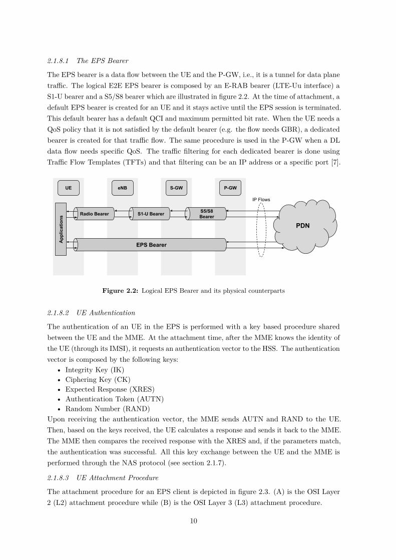
The EPS bearer is a data flow between the UE and the P-GW, i.e., it is a tunnel for data planetraffic. The logical E2E EPS bearer is composed by an E-RAB bearer (LTE-Uu interface) aS1-U bearer and a S5/S8 bearer which are illustrated in figure 2.2. At the time of attachment, adefault EPS bearer is created for an UE and it stays active until the EPS session is terminated.This default bearer has a default QCI and maximum permitted bit rate. When the UE needs aQoS policy that it is not satisfied by the default bearer (e.g. the flow needs GBR), a dedicatedbearer is created for that traffic flow. The same procedure is used in the P-GW when a DLdata flow needs specific QoS. The traffic filtering for each dedicated bearer is done usingTraffic Flow Templates (TFTs) and that filtering can be an IP address or a specific port [7].
UE eNB S-GW P-GW
EPS Bearer
S1-U Bearer S5/S8 BearerRadio Bearer
App
licat
ions
PDN
IP Flows
Figure 2.2: Logical EPS Bearer and its physical counterparts
2.1.8.2 UE Authentication
The authentication of an UE in the EPS is performed with a key based procedure sharedbetween the UE and the MME. At the attachment time, after the MME knows the identity ofthe UE (through its IMSI), it requests an authentication vector to the HSS. The authenticationvector is composed by the following keys:
• Integrity Key (IK)• Ciphering Key (CK)• Expected Response (XRES)• Authentication Token (AUTN)• Random Number (RAND)
Upon receiving the authentication vector, the MME sends AUTN and RAND to the UE.Then, based on the keys received, the UE calculates a response and sends it back to the MME.The MME then compares the received response with the XRES and, if the parameters match,the authentication was successful. All this key exchange between the UE and the MME isperformed through the NAS protocol (see section 2.1.7).
2.1.8.3 UE Attachment Procedure
The attachment procedure for an EPS client is depicted in figure 2.3. (A) is the OSI Layer2 (L2) attachment procedure while (B) is the OSI Layer 3 (L3) attachment procedure.
10

eNodeB MME HSS S-GW P-GW
(1) Attach Request
(2a) Identity Request
(2b) Identity Response(3a) Auth Info Request
(3b) Auth Info Answer(4a) Authentication Request
(5a) Security Mode Command
(5b) Security Mode Complete
(4b) Authentication Response
(6a) Update Location Request
(6b) Update Location Answer
(7a) Create Session Request
(7b) Create Session Response
(8a) Create Session Request
(8b) Create Session Response
(9a) Initial Context Setup Request
(9b) Initial Context Setup Response
(10) UE Capability Indication
(11a) Modify Bearer Request
Default Bearer
(11b) Modify Bearer Response(12) Attach Complete
(A)
(B)
UE
Figure 2.3: EPS Attachment Procedure
1. The eNB forwards the Attach Request received by the UE in a S1-MME control message(initial UE message) indicating an attach and PDN connectivity request.
2. The MME sends an Identity Request to the UE to request the IMSI. The UE respondswith Identity Response (IMSI).
3. After knowing the UE’s identity, the MME uses the HSS to retrieve the authenticationvectors via the Authentication Information Request DIAMETER message.
4. MME sends an Authentication Request to the UE with the authentication parametersAUTN and RAND. The UE responds with RES.
5. MME checks if the received RES corresponds to the one retrieved from HSS in theauthentication vector and, in case it does, the MME sends a security mode commandtowards the UE to configure the security parameters for UE’s communication. The UEthen responds with a security mode complete.
6. The MME updates the location of the UE in the HSS.7. The L2 attachment is now complete and the MME initiates the L3 attachment procedure
by sending a Create Session Request to the S-GW in order to obtain an IP address forthe UE.
8. The S-GW creates the context related to the UE, creates a GTP tunnel endpoint andforwards the message to the P-GW which in turn allocates an IP address for the UEto use in this PDN connection, creates the context for the UE, creates a GTP tunnel
11

endpoint and sends the Create Session Response to the S-GW with the allocated IPwhich in turn updates the UE context. After receiving the TEID from the P-GW theS5/S8 bearer is now established. The S-GW then creates a GTP tunnel endpoint forthe S1-U bearer and sends a Create Session Response to the MME.
9. The MME updates the context for this UE and sends the information sent by the S-GWto the UE via an Initial Context Setup Request message. The eNB, upon receiving theresponse to the message by the UE, creates a GTP tunnel endpoint for the S1-U bearerand communicates the TEID to the MME.
10. The UE communicates to the MME the radio access capabilities it possesses.11. The MME updates the UE context and it sends a Modify Bearer Request towards the
S-GW. When the S-GW receives information of the eNB S1-U tunnel endpoint, theS1-U bearer is now established and the UE has connectivity to the PDN. The ModifyBearer Response indicates the success of the attachment.
12. The MME sends the Attach Complete message to eNB. After this, the bearer isestablished.
2.2 3GPP to Non-3GPP Traffic Offloading Techniques
Wi-Fi, based on the IEEE 802.11 standard [12] is one of the most wide-spread unlicensedradio access technology. To take advantage of this technology, the first approach to offloaddata to WLAN might be to carefully deploy access points in a certain area. In the survey[13] the benefits of offloading traffic are analysed. By using AP deployment and modellingit, it is shown that, by deploying 10 APs/km2 the average user throughput can increase by300 percent while the number of users experience service outage of some sort decrease by 15percent compared with the case where only cellular networks are used. Simulation resultsshow that it is possible to lower the amount of cellular traffic by 20 to 70 percent, dependingon the number of deployed APs in a certain area. On the other hand, a very high AP densitycould degrade the performance of the WLAN due to mutual interference and the optimal APdeployment layout today might not be optimal tomorrow.
3GPP defines ways to provide connectivity to users through the EPC via non-3GPP accessnetworks either by aggregating LTE and WLAN traffic at the core network or at the accessnetwork. Various methods have been proposed by 3GPP and the main are as follows:
1. Access Network Discovery and Selection Function (ANDSF);2. LTE-WLAN Aggregation (LWA);3. LTE-WLAN radio-level integration with IP security tunnel (LWIP).
Other offloading mechanisms where also specified like Local IP Access (LIPA) (which requiresthe use of a Home eNodeB (HeNB)) and IP Flow Mobility (IFOM) which requires a newPDN connection resulting in IP address modification and breakage of data flows not allowingfor a seamless offload. For the reasons presented, these two methods are not deepened butthe reader can refer to [14] and [15] for more information and comparison. Other offloadingmechanisms are proposed by academia and industrial partners based on novel concepts ofSDN and are presented in the following subsections.
12

2.2.1 Access Network Discovery and Selection Function (ANDSF)
An architecture to interconnect LTE with WLAN is defined for trusted and un-trusted WLANaccess however, it is up to the operator to decide if a certain non-3GPP access network is tobe treated as trusted or untrusted. For the purpose of this thesis only the architecture fortrusted WLAN access is mentioned. This support for WLAN connectivity is added to figure2.1 and it is illustrated in figure 2.4 [16]. Analysing the figure, we can see that some interfacesand functional blocks were added in order to support this feature. In this architecture, the
MME
S-GW P-GW
HSS
PCRF
External Networks/Operator Services
S6a
S11 Gx
Rx
S5/S8S1-U
S1-MME
SGi
Control-Plane
eNB
LTE-Uu
UE
Data-PlaneAAA
WI-FI AP
S2a
WI-FI
SWx
STa
GxaANDSF
S14
Figure 2.4: EPS with WLAN Support
functional block AAA shall support Extensible Authentication Protocol-Authentication andKey Agreement (EAP-AKA) based authentication. This key exchange based authentication issimilar to the authentication process described in section 2.1.8.2. Interface STa connects thetrusted non-3GPP access with the 3GPP AAA Server and transports access authentication,authorization, mobility parameters and charging-related information in a secure manner.Interface SWx [17] is used to transport authentication (authentication vectors), subscriptionand PDN connection related data. This interface is implemented as a DIAMETER application.Interface Gxa provides transfer of QoS policy information from PCRF to the non-3GPP access.S2a interface is the data plane interface which carries, using a tunnelling protocol, the UEdata flows from the WLAN AP to the P-GW.
In this architecture the ANDSF [18] is the entity responsible for providing the UE withthe policies for access network selection (e.g. list of Service Set Identifiers (SSIDs)) and trafficrouting, assisting the UE in network discovery and handover process. So, ANDSF can beseen as the trigger mechanism for LTE to WLAN offloading. Despite the policies providedby the ANDSF, they have a lower priority than user preferences. With this information, theUE constructs a prioritized list of selected WLAN access networks and will try to connectto the one that has the highest priority, performing a 3GPP based authentication. Afterthe successful authentication, a tunnel is established between the P-GW and the WLAN
13

AP for the transport of data plane traffic. After the UE is connected to a PDN throughnon-3GPP access, an handover between 3GPP and non-3GPP occurs. The P-GW triggers a3GPP bearer release or bearer deactivation, disabling the communication flow of the UE viaLTE interface. In this type of handover the traffic flows are completely moved from 3GPP tonon-3GPP access.
2.2.2 LTE-WLAN Aggregation (LWA)
The LWA can be implemented in a non-collocated scenario for a non-ideal backhaul or in acollocated scenario for an ideal backhaul. As can be derived by the name, in the collocatedscenario the LTE and WLAN access point are integrated in a single entity. This architectureis not able to utilize the already deployed APs so a non-collocated scenario is also defined.Figures 2.5 and 2.6 present the protocol architecture for both scenarios.
Figure 2.5: LWA for Collocated Scenario [4]
Figure 2.6: LWA for Non-Collocated Scenario [4]
From the figures we can identify three types of bearers in use: the already mentioned LTEbearer, a split LWA bearer and a switched LWA bearer. The split LWA bearer enables a UEto use both access technologies simultaneously, allowing for a peak data throughput equal tothe sum of the peak data throughput of each of the links. In the switched LWA bearer onlyone access technology is used by the UE at a given time, switching the flows entirely fromLTE to WI-FI, releasing LTE resources, or vice versa.
14

2.2.3 LTE-WLAN radio-level integration with IP security tunnel (LWIP)
In this type of licensed and unlicensed spectrum integration no modifications are required tothe WLAN infrastructure. In this architecture the IP packets transferred between the UEand the LWIP-Security Gateway (SeGW) are encapsulated using IPsec in order to providesecurity for WLAN packets. The protocol architecture for this integration is illustrated infigure 2.7. The LWIP-SeGW can be collocated jointly with the eNB or non-collocated. The
Figure 2.7: LWIP Architecture [4]
two major differences between the two presented aggregation methods at the access networkare in the layers at which the flows are aggregated. While in LWA the flows are aggregatedat the Packet Data Convergence Protocol (PDCP) layer, in LWIP the flows are aggregatedat the IP layer. Both architectures standardized by 3GPP require changes to the eNB sincethese procedures are RAN controlled and transparent to the core network, using the alreadyestablished LTE bearers. These architectures are able to reuse the security provided by thecellular network.
[19] presents a comparison between the LWA and LWIP defined by 3GPP and presentedearlier with the conclusion that, in terms of data plane traffic, LWA outperforms LWIP byachieving approximately 40 percent higher data rates and 25 percent higher network capacityat any load.
2.2.4 New Approaches
The Seamless Internetwork Flow Mobility (SIFM) architecture for flow mobility is presented in[20] and it is compared with the seamless data offloading based on Proxy Mobile IPv6 (PMIPv6)[21] through simulations. The PMIPv6 is a protocol based on the Mobile IPv6 [22] and itis intended to provide network-based IP mobility management to a mobile node without
15

requiring the participation of the mobile node in any IP mobility related signalling. Thearchitecture presented in the paper supports selective flow offloading using a concept similarto that of SDN (presented in section 2.4.3). When the SIFM and the PMIPv6 flow mobilityarchitectures are compared with a scenario where no offloading occurs, the SIFM showsimprovements of 13.86 percent in terms of delay, 29.05 percent in terms of throughput and11.33 percent in terms of packet loss while the PMIPv6 shows improvements of 7.96 percent,19.52 percent and 7.83 percent respectively.
[23] proposes an architecture integrated in the EPC to seamlessly offload traffic betweenLTE and WLAN with EAP-AKA authentication. In this paper the authors propose toimplement two functional blocks for the WLAN control. One of these blocks is the AccessZone Control. This functional block is similar to a cache memory for user authentication.When a certain user is offloaded to WLAN it is authenticated using the EAP-AKA. Aftera successful authentication, the authentication parameters are stored so that when a usermoves from the current WLAN AP to another (within the same zone), the authenticationparameters are already stored, lowering the authentication delay. Another functional blockproposed in the paper is the Access Network Query Protocol-Data Server which is responsiblefor WLAN AP selection and QoS provisioning. The proposed architecture was simulated andthe results indicate that, with this architecture, the handover delay between APs is reduced byaround 58 percent, assuming that the offloading from LTE and WLAN had occurred earlier[23].
The cited related work presents interesting propositions to interconnect and offload trafficbetween LTE and WLAN however, there are very few practical implementations of theproposed architectures since the majority is validated through simulations. Despite the efforts,a physical testbed for the entire EPS system with support for WLAN offloading is yet toappear.
2.3 The road to 5G
2.3.1 5G Core Architecture
In recent years, 5G has been drawing attention worldwide as an enabler for a more efficientand cost effective network, allowing for new business opportunities. Standardization effortshave been made by 3GPP which produced release 15 of specifications related to the 5G NR[24] and Core Network [25]. The 5G system was defined to support data connectivity andservices enabling deployments to use techniques such as NFV and SDN. It shall leverageservice-based interactions between control plane NFs. To allow independent scaling, evolutionand flexible deployments 5G separates the data plane from the control plane. To enableflexible and efficient network slicing the network function design is highly modular. Other keyprinciples of 5G were to support a unified authentication framework, minimize dependenciesbetween the access and core networks and converge 3GPP and non-3GPP access. The 5Gnetwork architecture standardized by 3GPP for non-roaming scenario is presented in figure 2.8.In order to avoid the repetition of interfaces between NFs, service based interfaces are used
16

within the control plane. Using this approach there is only one interface in each NF and allinterfaces are interconnected using a bus like connection. Related to the authentication, it isperformed using 5G-Authentication and Key Agreement (AKA) for 5G access and EAP-AKAfor non-3GPP access.
Figure 2.8: 5G System Architecture [25]
On the lower half of the figure is the data plane while the control plane is representedat the top half. Like in the EPS, the traffic flowing between the Access Network (AN) andthe gateway is encapsulated using GTP. The logical signalling between the UE and the 5Gcore network uses specific 5G NAS protocol such as NAS-AM for Access and Mobility relatedsignalling and NAS-SM for Session Management signalling. 5G standards also provide a wayto support multi-access edge computing, a technology that enables operators or 3rd partyservices to be hosted closer to the UE’s access point, achieving an efficient service deliverythrough reduced E2E latency and load on the transport network. This can be achieved byselecting a UPF that is close to the UE and then executing traffic steering from the UPFto the local data network using the N6 interface. A functional description of the networkfunctions is now provided.
2.3.1.1 Access and Mobility Management Function (AMF)
The AMF is the termination of the RAN control plane interface (N2) and it can be seen asthe equivalent of theMME from the EPS. The main functions it performs are as follows:
• Termination of NAS, NAS ciphering and integrity protection;• Management of Registration, Connection, Reachability and Mobility;• Provide Transport for Session Management messages between the UE and the SMF;• Access Authentication and Authorization;• Security Context Management;• EPS bearer ID allocation for interworking with EPS;• Support for authentication of UEs connected over Non-3GPP InterWorking Function
(N3IWF) (non-3GPP access, see section 2.3.2);
17

2.3.1.2 Session Management Function (SMF)
The SMF can be seen as the evolved control part of the S-GW and the P-GW and part ofthe MME. The main functions it performs are:
• Session Management, i.e., Session Establishment, modify and release, including tunnelmaintenance between the UPF and the AN node;
• UE IP address allocation and management;• DHCPv4 and v6 functions;• Address Resolution Protocol (ARP) proxy as specified in [26];• Configure traffic steering at UPF for traffic routing;• Control and coordination of charging data collection at UPF;• Termination of SM parts of NAS messages;• Downlink data notification;• Roaming functionality.
2.3.1.3 User Plane Function (UPF)
The UPF is the gateway for traffic originating in the AN and can be seen as an equivalententity to the EPS data plane of S-GW and P-GW combined. Like in the EPS, the traffic iscarried from the AN to the UPF inside a GTP tunnel. The main functions performed by thisnetwork function are:
• Anchor point for intra-/inter-Radio Access Technology (RAT) mobility;• External Packet Data Unit (PDU) session point of interconnection to the Data Network
(DN);• Packet Routing, Forwarding and inspection.• Policy Enforcement;• Lawful Interception;• Traffic usage reporting;• UL/DL rate enforcement, QoS marking in DL and SDF to QoS flow mapping;• DL packet buffering and data notification triggering;
2.3.1.4 Policy Control Function (PCF)
The PCF is equivalent to the PCRF from the EPS. It is responsible for accessing thesubscription information relevant for policy decisions in a Unified Data Repository (UDR)that will be provided to the control plane functions to enforce them. This policy frameworkgoverns the network behaviour.
2.3.1.5 Unified Data Management (UDM)
The UDM has some functionalities inherited from the HSS. It is responsible for the generationof 3GPP AKA authentication credentials, handle user identification, access authorizationbased on subscription data and subscription management. The UDM can interwork with aseparate entity called UDR that will be used for storing data while the UDM only performsthe application logic and does not require internal user data storage.
18

2.3.1.6 Application Function (AF)
The AF interacts with the core network in order to provide services. It enables applicationinfluence on traffic routing, provides access to the NEF and interacts with the policy frameworkfor policy control.
2.3.1.7 Network Exposure Function (NEF)
The NEF enables 3GPP NFs to expose their capabilities and events to other NFs throughan API. As an example, network functions exposed capabilities and events may be securelyexposed for edge computing applications. The NEF also handles the masking of networkand user sensitive information to external AFs according to the network policy. It translatesbetween information exchanged with the AF and information exchanged with the internalnetwork function.
2.3.1.8 Network Slice Selection Function (NSSF)
This network function is related to the new concept of network slicing. The NSSF is responsiblefor selecting the set of network slice instances serving the UE as well as determining the AMFset to be used to serve the UE.
Since the 5G core network is an evolution of the EPC, table 2.3 presents a mappingbetween some of the 4G and 5G network functions. Some other network functions wereintroduced for the first time in 5G and thus are not presented in the table.
4G 5GMME AMFMME, S-GW and P-GW (Control Plane (CP)) SMFP-GW and S-GW DP UPFPCRF PCFHSS UDM
Table 2.3: Mapping between 4G and 5G network functions
2.3.2 WLAN interworking
Taking into consideration the need to interconnect non-3GPP access (e.g. WLAN) into the5G core, 3GPP defines a way to do so with the additions presented in figure 2.9. The handoverfrom 3GPP to non-3GPP access at the core network level imposes that the complete PDUsession is transferred to the access network in question, releasing the previously establishedsession. In the architecture, a new network function was added called N3IWF. This networkfunction supports the IPsec tunnel establishment with the UE by terminating the IPsecprotocols with the UE over the NWu interface and relays (over N2) the information neededto authenticate the UE and authorize the access to the 5G Core Network. Other N3IWFfunctions include:
• Relaying UL and DL control plane NAS signalling between the UE and AMF;• Handling of N2 signalling from SMF (relayed by AMF) related to PDU sessions and
QoS;
19
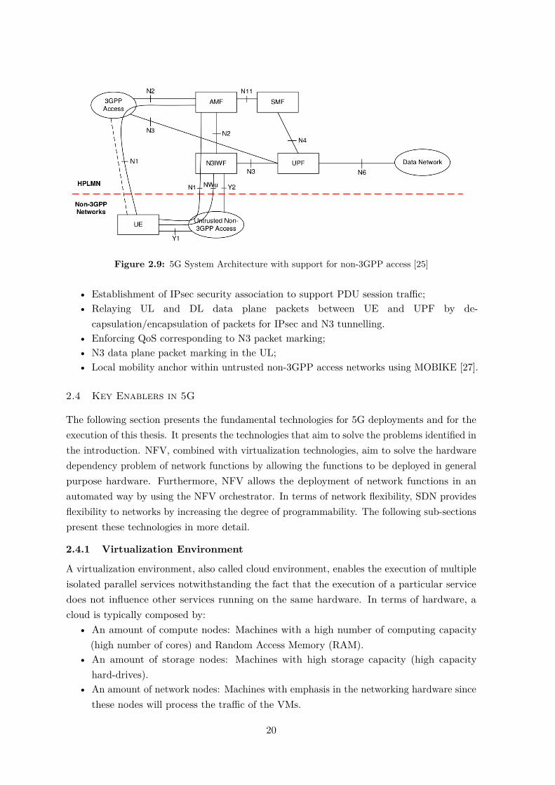
Figure 2.9: 5G System Architecture with support for non-3GPP access [25]
• Establishment of IPsec security association to support PDU session traffic;• Relaying UL and DL data plane packets between UE and UPF by de-
capsulation/encapsulation of packets for IPsec and N3 tunnelling.• Enforcing QoS corresponding to N3 packet marking;• N3 data plane packet marking in the UL;• Local mobility anchor within untrusted non-3GPP access networks using MOBIKE [27].
2.4 Key Enablers in 5G
The following section presents the fundamental technologies for 5G deployments and for theexecution of this thesis. It presents the technologies that aim to solve the problems identified inthe introduction. NFV, combined with virtualization technologies, aim to solve the hardwaredependency problem of network functions by allowing the functions to be deployed in generalpurpose hardware. Furthermore, NFV allows the deployment of network functions in anautomated way by using the NFV orchestrator. In terms of network flexibility, SDN providesflexibility to networks by increasing the degree of programmability. The following sub-sectionspresent these technologies in more detail.
2.4.1 Virtualization Environment
A virtualization environment, also called cloud environment, enables the execution of multipleisolated parallel services notwithstanding the fact that the execution of a particular servicedoes not influence other services running on the same hardware. In terms of hardware, acloud is typically composed by:
• An amount of compute nodes: Machines with a high number of computing capacity(high number of cores) and Random Access Memory (RAM).
• An amount of storage nodes: Machines with high storage capacity (high capacityhard-drives).
• An amount of network nodes: Machines with emphasis in the networking hardware sincethese nodes will process the traffic of the VMs.
20

In a virtualization environment there is an abstraction layer for the hardware provided by theVirtual Infrastructure Manager (VIM) which aggregates the available hardware into resourcepools that are called here Virtual Compute, Virtual Storage and Virtual Network. The virtualcompute resource pool translates in the available Central Processing Unit (CPU) cores andRAM of all the compute nodes combined. As for the virtual storage resource pool it aggregatesthe total capacity available across all the storage nodes. The virtual network resource poolcomprises all the virtual networks that can be created. This enables the infrastructure managerto easily increase the capacity of a cloud in terms of either compute, storage or network sincefrom a user point of view, it only translates in an increase of the amount of available resourcesin the resource pool. The VIM then enables the creation of VMs that use the resource pools,independently of the infrastructure layout. Figure 2.10 depicts the layout of a virtualizationenvironment. Some available VIMs include Openstack4, Proxmox5 and openVIM6. In recent
Infrastructure
Compute 2
Compute 1
...
Compute X
Storage 2
Storage 1
...
Storage Y
Network 2
Network 1
...
Network Z
Virtual Compute Virtual Storage Virtual Network
Virtual Machines
Virtual Infrastructure Manager
Figure 2.10: Infrastructure Virtualization
years Openstack is becoming the de-facto standard VIM for telecommunication deployments.
2.4.2 Network Function Virtualisation (NFV)
The NFV reference architecture, standardized by the European Telecommunications StandardsInstitute (ETSI) [28], is depicted in figure 2.11. In the figure we can identity the VIM thatwas described in the previous section, the Virtual Network Functions (VNFs) and the VNFMANO. Current networks are composed by several different network functions which arechained or connected in a certain way in order to provide a network service or functionalityusing vendor specific hardware. NFV enables an operator to drop the dependencies it has
4Openstack: https://www.openstack.org/5Proxmox: https://www.proxmox.com/en/6openVIM: https://github.com/nfvlabs/openvim
21

Figure 2.11: NFV Reference Architecture [28]
with the proprietary hardware being able to deploy the NFs in a virtualization environmentusing NFV.
In relation to legacy networks, NFV introduces some differences in how network functionprovisioning is realized by decoupling software from hardware, enabling the use of generalpurpose hardware and enabling software and hardware to evolve independently. In this way,the deployment of NFs can be performed in an automated way and it allows for a dynamicoperation in the sense that an operator could scale a NF up or down in function of the loadon the network.
2.4.2.1 NFV Management and Orchestration (MANO)
The NFV MANO was introduced to properly manage VNFs, enabling network automation.From figure 2.11 we can identify the NFV MANO which is composed by the Network FunctionVirtualization Orchestrator (NFVO), by the Virtual Network Function Manager (VNFM)and by the VIM (already presented in the previous section). These functional blocks of theNFV reference architecture are needed to manage and orchestrate the relationship betweenthe VNFs and the the Network Function Virtualization Infrastructure (NFVI) as well as tomanage the interconnection of VNFs and/or Physical Network Functions (PNFs) in orderto realize a Network Service (NS). The NFVO is responsible for orchestrating the resourcesneeded for the VNFs in the VIM and to manage the life-cycle of NS. On the other hand,VNFM is responsible for the life-cycle management of VNFs [29].
22

2.4.2.2 Virtual Network Function (VNF)
A VNF is a software implementation of a NF that can be deployed in a virtualizationenvironment. The deployment of a VNF is performed according to a Virtual Network FunctionDescriptor (VNFD) that contains the properties of the VNF such as number of Virtual NetworkFunction Components (VNFCs), resources utilized by each one or connected interfaces. Afunctional view of a VNF according to ETSI is depicted in figure 2.12. A VNF can be deployed
Figure 2.12: Functional view of a VNF [30]
in a single VM or it can be composed by several VMs called VNFCs that are interconnectedto form the desired VNF. These VNFCs can be parallelizable or non-parallelizable whichmeans that, a parallelizable VNFC can have multiple parallel VNFCs performing the sametask. Also, the VNFCs may need to maintain their state either by maintaining it internally(stateful VNFC) or by using an external state (VNFC with externalized state) [30].
ETSI specifies in [28] that the interfaces between VNFCs do not need to obey a stan-dardization and can rather be implemented in a way that maximizes the VNF performance.Only the external interfaces have to be implemented according to standards. The VNF asstandardized by ETSI has the SWA-1 interface that interconnects the VNF with the outside.This interface must obey standards, e.g., identify the VNF in question as a S-GW from theEPS. In this case the SWA-1 interfaces must be implemented according to the standards ofthe S1-U, S11 and S5/S8 interfaces. The SWA-2 is the internal connection between VNFCsand, as already stated, does not need to be implemented according to any standards andcan be implemented in a way that offers maximum performance in the considered use case.Interface SWA-3 is the connection between the VNF and the VNF Manager. This manager isresponsible for the life cycle of the VNF being responsible for its instantiation, scaling, etc.The SWA-4 interface is used to communicate with the Element Manager (EM) for runtimemanagement and resource utilization monitoring. Finally, the SWA-5 interface is used for
23

operations related to the underlying hardware such as compute, storage and/or networkingoperations.
Another important feature of NFV is its scaling capability. In this context, scaling refersto either adding (or removing) a parallel VNFC to the VNFCs already in use (scale in/out)or adding (or removing) resources to the VNFCs already deployed (scale up/down). Thescale in/out requires that a VNFC is parallelizable and it is able to scale both stateless andstateful VNFCs as well as VNFCs with external state. Typically, three basic scaling modelsare defined for both scaling up or down:
• Auto Scaling, where the VNF Manager triggers the scaling of a VNF based on themonitoring of resource utilization of the VNF’s VMs and according to the rules definedin the VNFD. This type of scaling supports scaling in/out and up/down.
• On-demand Scaling, in which a VNF instance or it’s EM monitors the state of theVNFCs and triggers a scaling operation by explicitly requesting to the VNF Managerto add or remove VNFC instances or increase or decrease the resources available for oneor more VNFCs.
• Scaling based on a management request that can be manually triggered.
2.4.3 Software Defined Networking (SDN)
SDN is a mechanism that separates the control plane from the data plane (also known asforwarding plane) and centralizes it, providing a high level of network programmability andallowing for a dynamic network (re)configuration. By centralizing the control plane it becomespossible to have a full view of the network and configure the forwarding elements of the DataPlane as needed. The technical document [31] provides a description of the layers of SDNand an architecture terminology. Despite several SDN planes being mentioned on the citeddocument, for the purpose of this thesis, the focus will be on the Application Plane, CP,Management Plane (MP) and DP. Figure 2.13 provides a visual representation of this planesand the relation between each other.
Control Plane
Data Plane
Application Plane
CPSouthboundInterface
Northbound Interface
APP 1
APP 2
Forwarding Plane Operational Plane
Management Plane
MPSouthboundInterface
Figure 2.13: Main SDN Planes (adapted from [31])
24

2.4.3.1 Data Plane
The Data Plane is composed by network devices (either physical or virtual) that receive packetsand perform one or more functions on them. This entity can also have some applications suchas ARP, instead of sending such traffic to the Control Plane. The Data Plane has two subplanes: The forwarding plane which is responsible for packet processing and the OperationalPlane which is responsible for providing information related to the status of the device to theManagement Plane and receive and execute commands received by it. The Operational Planeterminates the MP Southbound Interface and it’s implementation is vendor specific. As anexample, OVS7, which is an OpenFlow switch, uses it’s own protocol for this interface, theOVSDB protocol.
Regarding to the forwarding functions of the Data Plane, when the Data Plane devicereceives a packet it can forward the received packet, drop it or modify the headers or payload.Other actions that can be performed by the Data Plane elements include filtering of packets,meters, markers and classifiers. These actions are performed based on rules previouslyprovided by the Control Plane using the CP Southbound Interface. Several protocols areused for this interface such as ForCES [32], YANG model [33] and OpenFlow [34], which hasbecome one of the most commonly deployed protocols, being defined by the Open NetworkFoundation (ONF)8. Because the OpenFlow protocol is the most used and it was relevant forthe execution of this thesis it is explained in more detail in the following section.
2.4.3.1.1 OpenFlow Protocol.The OpenFlow protocol [34] defines the architecture of an OpenFlow Logical Switch as wellas the messages exchanged between the Control Plane and the Data Plane entities. Figure2.14 shows the main components of an OpenFlow switch. This switch is composed by one ormore flow tables, a group table and one or more OpenFlow channels to communicate with anexternal controller (Control Plane). The flow tables contain flow entries that consist of:
• Match Fields that will be compared against the fields of a received packet;• Counters that monitor parameters such as the number of packets that matched that
particular flow entry;• A set of instructions to apply to matching packets. These instructions can be to modify
the packet’s fields, drop the packet, send the packet to the controller or forward thepacket.
The OpenFlow protocol allows a controller to add, update and delete flow entries in flowtables both reactively and proactively. The typical packet processing flow in an OpenFlowswitch is as follows:
1. The received packet is compared against the flow entries match fields contained in thefirst flow table. If there is a match, the corresponding instructions are executed. Theflow entries are prioritized so, if there is more than one flow entry match, the flow entrywith the highest priority is the one that prevails. The standard action to perform for a
7Openvswitch: https://www.openvswitch.org/8Open Network Foundation: https://www.opennetworking.org/
25

Figure 2.14: Main Components of an OpenFlow Switch [34]
packet that does not match any flow entry is to send it to the Control Plane entity forfurther processing.
2. If there are instructions that modify the packet’s fields, they are executed.3. After the modifications are made to the packet it can now be forwarded or sent to
another flow table where the execution described here is repeated.
2.4.3.2 Control Plane Entity
The Control Plane is responsible for providing the Data Plane with the information on howto process certain packets or traffic flows. It is the entity that has a knowledge about thenetwork topology and makes decisions on how packets must be treated, pushing then thisinformation to the Data Plane. Control Plane functionalities usually include:
• Topology discovery and maintenance;• Packet route selection;• Path failover mechanisms.
The Control Plane receives information from applications in the Application Plane through theNorthbound Interface. Examples of protocols used for the Northbound interface are RESTfulAPIs and Network Configuration Protocol (NETCONF). The two leading approaches for thisinterface are the use of RESTful interfaces and Routing Control Platform (RCP) [35] interfaces.Both follow a client-server model and use eXtensible Markup Language (XML) or JavaScriptObject Notation (JSON) to pass messages. The Control Plane is where the SDN controllerresides. Several controller implementations are available such as OpenDaylight (ODL)9,ONOS10 and RYU11.
9OpenDayLight: https://www.opendaylight.org/10ONOS: https://onosproject.org/11RYU: https://osrg.github.io/ryu/
26

2.4.3.3 Management Plane
The Management Plane is the entity responsible for monitoring, configuring and maintainingData Plane devices. It can bring up ports or shut them down. The Management Planecan help the Control Plane with load balancing operations by providing information aboutresource utilization.
2.4.3.4 Application Plane
This is the plane where services and applications that use network services run. There can bemultiple simultaneous applications sharing the same underlying network. The Control Planeprovides to applications an abstraction layer of the underlying network topology.
2.4.4 Virtualizing the EPC
Having by base the 4G network, efforts are being done to evolve it towards a more flexible andcost-effective network, paving the way for 5G. In [36] the authors propose a way to re-designthe LTE EPC using two approaches: SDN-based EPC and NFV-based EPC. While the formerimplements the control plane functions of the EPC as applications on top of an SDN controller(installed on a physical machine) and an SDN switch for the data plane functions, the latterimplements the functions as software modules running on VMs hosted in a private cloud. Totest the implementation the authors used a simulated eNB and UE and concluded that theSDN-based approach has a better performance when coping with high data plane traffic buthas a lower control plane performance when compared with the NFV-based approach, sincethe communication with the SDN controller becomes a bottleneck.
In [37] the authors make a qualitative study of an SDN-based EPC in a cloud environmentusing an approach where all EPC functions are virtualized and another approach whereonly the control plane is instantiated in the cloud leaving the packet forwarding functionsto SDN capable switches. Even though the paper presents the expected behaviour of bothimplementations, saying that the KPIs degrade as more EPC functions are virtualized, it failsto present real implementation values.
[38] revises the control plane of the current LTE EPC using SDN in order to enableon-demand connectivity service, focusing on resiliency and load-balancing. In the mentionedwork, the authors replaced the standard S1-MME and S11 interfaces with the openflowprotocol. However, no practical implementation or testing was performed.
[39] presents a comparison between a software only EPC and a SDN powered EPC focusingin the Total Cost of Ownership (TCO) of each approach. In the software only approach allEPC functions are implemented as VNFs in a datacenter while in the SDN approach thecontrol plane is also realized in the datacenter. However, the data plane is implemented usingSDN switches, alleviating the packet processing from the datacenter. Results from this papershow that realizing EPC gateway functions entirely in software will be much more expensivecompared to the approach where SDN switches are used. Similarly, [40] also compares thesetwo approaches to EPC virtualization but focusing instead on the impact of the virtualizationin terms of network load. The simulated results show that in a pure NFV implementation the
27

packet processing delay increases with the increase of the number of attached bearers whilein the SDN approach, using SDN switches, the packet processing delay is not related to thenumber of active bearers and it is around 9 times lower when there are 10k active bearers.
Another approach to virtualize the evolved packet core using NFV and SDN instead ofthe traditional distributed IP routing control is presented in [41]. In this work an extensionto the OpenFlow 1.2 protocol is proposed in order to support GTP TEID routing extensions.No practical results are presented in this paper.
All these efforts in virtualizing the EPC are an important step ahead for 5G deploymentswhich aim to be enabled by the technologies discussed in the referenced papers. The mentionedworks also show that the control and data plane separation benefit the performance of the corenetwork since one can implement these functions with different performance characteristics(signalling processing vs packet processing oriented). Many of the studies performed showthat a hybrid approach for the virtualization (control plane in the cloud, data plane usingSDN switches) of the EPC benefits the users in terms of latency and spares the datacentersof the packet processing. However, this approach requires specific hardware and not only thegeneral purpose servers.
2.5 Summary
This chapter presented the state of the art of the evolution from 4G to 5G networks and newapproaches for traffic offloading techniques. It presented standardization efforts by 3GPPrelated to both 5G networks and traffic offloading as well as other works that attempt to evolvethe EPC into a network that is closer to 5G. Although various works propose mechanismsto evolve the EPC, few physical implementation test-beds are available. Furthermore, thechapter also presented the key technologies that are likely to drive the future 5G deployments.These technologies, when combined, allow a telecommunications operator to deploy a moreflexible, reconfigurable and cheaper network. They also provide a platform for new servicesand business opportunities. The next chapter presents the design of the proposed architectureto evolve the EPC using the key technologies presented in this chapter.
28

CHAPTER 3Architecture Design
The following chapter presents the decisions made in terms of the architecture’s design. Thegoal is to take the EPC as defined by 3GPP, separate the control plane from the data planeusing SDN, deploy the architecture in a cloud environment, add support for Wi-Fi and 3GPPto non-3GPP traffic offloading.
3.1 Overview
Figure 3.1 presents the overall architecture design. A separation between the LTE controlplane, the Wi-Fi control plane and the data plane was designed following the SDN mainplanes presented in section 2.4.3. Related to the S-GW and the P-GW, these entities weregrouped into a single entity called the S/P-GW. Several reasons contributed for this decision:
• 3GPP specifies that the usage of the S-GW and the P-GW as separate entities or as asingle entity is vendor specific (see section 2.1.5).
• This architecture is not intended to be used in a roaming scenario as defined by 3GPP,although it can also support this scenario if the S/P-GW from the Home-Public LandMobile Network (H-PLMN) is connected to the one in the Visitor-Public Land MobileNetwork (V-PLMN). Although this scenario is possible, it does not follow the 3GPPstandards.
• By suppressing the S5/S8 interface, the attachment time is reduced since there is oneless interface introducing latency in the attachment messages.
• Lastly, regarding to the data plane, there is also one less functional block for the trafficto traverse thus reducing the E2E latency viewed by the UE.
On the downside, by grouping two functional entities, two possible points of failure are beinggrouped into a single one which can be a downside.
In the presented architecture the UE needs to be equipped with a USIM card containingan IMSI. This IMSI will be used to identify the user in both the LTE and Wi-Fi networks.
In the next sections, the different architecture entities and planes will be described.
29

SDN Component
Data Plane
Wi-Fi Control Plane
MME
S/P-GW-U
HSS
External Networks/Operator Services
S6a
S1-U
S1-MME
Control-Plane
eNB
LTE-Uu
UE
Data-Plane
AAA
WI-FI AP
Wi-Fi
S/P-GW-C
SDN-CTRL
DHCPServer
CPSouthboudInterface
MPSouthboudInterface
LTE Northbound Interface
STa
STa-DHCP
SDN-Info
Wi-Fi Northbound Interface
SWx
S11
S2a
SGi
Wi-Fi CP Southbound Interface
LTE Control Plane
Figure 3.1: Full architecture design
3.2 Introducing SDN
The first step in the evolution of the EPC is to introduce SDN into the EPC defined by 3GPPand presented in section 2.1, thus providing a separation between the data plane and thecontrol plane. Figure 3.2 maps some network functions presented in figure 3.1 in the SDNplanes from section 2.4.3. Related to the design of the SDN in the architecture, a decisionwas made to group the CP and the MP into a single entity thus providing an abstractionlayer for the application plane where only one Northbound interface is needed for LTE controland another for Wi-Fi control. The design specifications and considerations for each one ofthese planes is presented in the following sub-sections.
30

Control Plane/Management Plane
Data Plane
Application Plane
CP/MPSouthboundInterface
Northbound Interfaces
S/P-GW-C DHCP-SERVER
SDN-CTRL
S/P-GW-U Wi-Fi-AP
Figure 3.2: Mapping between the main SDN planes and the architecture’s network functions
3.2.1 Data Plane
As for the data plane of the architecture, it’s main component is the S/P-GW-U which is, inthis architecture, an SDN switch coupled with the ability to establish GTP tunnels to theeNB and GRE tunnels to the Wi-Fi AP. The tunnel information shall be received by theSDN controller via the MP Southbound Interface. Furthermore, the S/P-GW-U must forwardtraffic to/from external networks or operator services. Before the traffic leaves towards externalnetworks or operator services, Network Address Translation (NAT) has to be performed on it.These forwarding rules are received by the SDN controller in the CP Southbound interface.The S/P-GW-U network function was designed in order to be as simple as possible, beingthat all the control is performed by the SDN controller. Another important feature that theS/P-GW-U needs to have is the ability to dynamically change the forwarding rules receivedby the controller so that it can perform traffic steering, for instance. The Wi-Fi AP will alsohave an SDN enabled switch that will assist in the tunnelling needed to carry UE traffic fromthe AP to the S/P-GW-U. This switch is also controlled by the SDN controller however, onlythe CP Southbound interface is needed since the AP’s initial configurations are processed atthe time of deployment.
3.2.2 LTE Control Plane
For the LTE control plane, the network functions HSS and MME should function just asspecified by 3GPP. The only network function that needs some modification is the S/P-GW-C.In this network function, a method needs to be implemented to provide information, throughthe Northbound Interface, to the SDN controller about UEs connecting to the LTE network.This information includes:
• IMSI;• Access Technology (e.g., LTE);• UE IP address;
31

• eNB IP address;• TEID for both endpoints of the tunnel.
The SDN controller then converts the information received in the LTE Northbound interfaceinto forwarding rules and MP Southbound interface commands.
3.2.2.1 Attachment Procedure
Figure 3.3 illustrates the attachment procedure for an LTE UE. The procedure is the same
eNodeB MME HSS S/P-GW-C SDN-CTRL
(1) Attach Request
(2a) Identity Request
(2b) Identity Response
(3b) Auth Info Answer(4a) Authentication Request
(5a) Security Mode Command
(5b) Security Mode Complete
(4b) Authentication Response
(6a) Update Location Request
(6b) Update Location Answer
(7a) Create Session Request
(7b) Create Session Response
(9) UE Capability Indication
(8a) Initial Context Setup Request
Default Bearer
S/P-GW-U
(3a) Auth Info Request
(8b) Initial Context Setup Response (10) Modify Bearer Request
(14) Modify Bearer Response
(11a) Add UE LTE(12a) Create GTP Tunnel Req
(12b) Create GTP Tunnel Resp
(13a) Install Forwarding Rules
(13b) ACK(11b) 200 OK
(15) Attach Complete
UE
Figure 3.3: Attachment procedure for a LTE client in the proposed architecture
as presented in section 2.1.8.3 up until step 10. So, from step 10 onwards, the procedure is asdescribed.11. The S/P-GW-C sends to the controller the UE’s information that includes the access
technology, the IMSI, the UE’s IP address, the IP address of the eNB and the TEIDfor both tunnel endpoints;
12. The SDN controller receives this information and creates a GTP tunnel (if it is notalready created) according to the eNB IP address and the TEIDs provided by theS/P-GW-C;
13. After the tunnel is created, the SDN controller installs the forwarding rules in the SDNswitch, directing the downlink traffic to the tunnel created in the previous step;
14. After the S/P-GW-C receives indication that the SDN procedure is complete it sendsthe Modify Bearer Response towards the MME.
3.2.3 Wi-Fi Control Plane
As for the Wi-Fi control plane, the DHCP server, in addition to the behaviour specified in[42], needs to have a mechanism that associates the IMSI of the user to the MAC address of
32

the Wi-Fi interface of the UE. Since the DHCP messages do not provide such information,this information will be received by the AAA server via a newly implemented interface calledSDN-Info. This information allows the DHCP server to associate the IP address to theuser’s IMSI. At the time of attachment, when an IP address is allocated for the UE’s Wi-Fiinterface, the DHCP server is responsible for providing the SDN controller with the followinginformation about the UE:
• IMSI;• Access Technology (e.g., Wi-Fi);• Interface MAC address;• UE IP address;• Wi-Fi AP IP address.
The TEID for Wi-Fi will be allocated by the SDN controller. This information is sent tothe SDN controller using the Wi-Fi Northbound Interface which converts this informationinto forwarding rules and MP Southbound Interface commands. So, in the AAA server, inaddition to what it is specified by 3GPP, a mechanism needs to be implemented to providethe necessary information to the DHCP server (i.e., an association between the IMSI and theMAC address).
3.2.3.1 Attachment Procedure
Figure 3.4 illustrates the attachment procedure of a UE connecting to the Wi-Fi network.
Wi-Fi AP AAA HSS DHCP-SRV SDN-CTRL
(1) Access Request
(3) Access Challenge
(4a) Access Request
(2b) Multimedia-Auth Answer
(4b) Access-Accept
GRE Tunnel
S/P-GW-U
(2a) Multimedia-Auth Request
(8a) Add UE Wi-Fi(9a) Create GRE Tunnel Req
(9b) Create GRE Tunnel Resp
(10a) Install Forwarding Rules
(10b) ACK
(8b) 200 OK
(5) IMSI/MAC Association
(6a) DHCP Discover
(6b) DHCP Offer
(7a) DHCP Request
(7b) DHCP ACK
(11a) Install Wi-Fi AP Forwarding Rules
(11b) ACK
UE
Figure 3.4: Attachment procedure for a Wi-Fi client in the proposed architecture
The attachment procedure is executed as described below.1. Upon receiving an attachment request from the UE, the Wi-Fi AP sends an Access
Request to the AAA with the user identification (i.e., IMSI);2. The AAA server sends a Multimedia-Auth Request to the HSS with the user’s IMSI
in order to retrieve the EAP-AKA authentication vector. The HSS calculates the
33

authentication vector and answers to the AAA server with a Multimedia-Auth Answer.This authentication vector is the same as the one presented in section 2.1.8.2;
3. After retrieving the authentication vector, the AAA server sends an Access Challengeto the Wi-Fi AP with the AUTN and RAND (refer to section 2.1.8.3);
4. With the received AUTN and RAND the UE calculates the RES parameter and sendsit to the AAA server through an Access Request message. This message also containsthe user’s IMSI, the UE’s MAC address of the Wi-Fi interface and the IP address ofthe Wi-Fi AP. The AAA server verifies if the RES parameter is equal to the XRESand, in case it does, the AAA server sends an Access Accept message towards the UEindicating a successful attachment. After this, the L2 attachment is complete;
5. After the AAA server verifies that the RES matches the XRES, it sends a message tothe DHCP server with the user’s IMSI, the MAC address of the Wi-Fi interface andthe Wi-Fi AP IP address. These parameters will allow the DHCP server to associate aMAC address to the IMSI and Wi-Fi AP IP address in a later stage of the attachment;
6. The UE now needs to request an IP address. This is done by sending a DHCP Discovermessage to the DHCP server. This message contains the MAC address of the UE’sWi-Fi interface. The DHCP server then allocates an IP address for the UE and sends itback through a DHCP Offer message. Besides the allocated IP address, this messagealso contains the subnet mask, lease time, i.e., the time until the UE has to make a newDHCP request (refer to [42]), the assigned Domain Name System (DNS), the interfaceMaximum Transfer Unit (MTU) and the broadcast address;
7. The UE sends a DHCP Request with the information contained in the DHCP Offermessage. The DHCP responds with a DHCP ACK. From this point on, from a UE’spoint of view, the L3 attachment is complete;
8. At the same time that the DHCP server sends the DHCP ACK message, it also sends amessage to the SDN controller (though the Wi-Fi Northbound interface) with the UE’sinformation (access technology, IMSI, MAC address, UE IP address and Wi-Fi AP IPaddress);
9. With the received information, the SDN controller allocates a TEID for the tunnel thatwill be created between the Wi-Fi AP and the S/P-GW-U. Then, it sends a CreateGRE Tunnel request message to the S/P-GW-U through the MP Southbound Interfaceto create the necessary tunnel;
10. After the tunnel is created, the SDN controller installs the necessary forwarding rules inthe S/P-GW-U to handle the UE’s packets;
11. The SDN controller also installs forwarding rules in the Wi-Fi AP in order to send UEtraffic through the respective tunnel. After this step, the data plane is ready to handlepackets belonging to the UE.
3.2.4 SDN Controller
The SDN controller is the main control entity of the proposed architecture. In this architecture,the SDN controller is composed by two controller applications: one that will store theinformation received by both the S/P-GW-C and the DHCP server about a user equipment’s
34
network interfaces thus having a representation of the UE, and another, called context updater,that implements a mechanism that enables to seamless offload traffic from LTE to Wi-Fi(see section 3.2.4.1). This mechanism consists in creating a Wi-Fi slice for a user, redirectingselective flows to the created slice. The mechanism dynamically instantiates a non-3GPPslice (i.e., Wi-Fi) by creating in an AP a new SSID to optimally serve the traffic flows viaWi-Fi (e.g., when congestion is detected on the mobile network). This results in an offloadingmechanism transparent to the user. A simplified slicing mechanism was used for experimentalpurposes, only to validate the offloading mechanism since more complex slicing mechanismsfall out of the scope of this thesis. In the controller, the identifier of the UE is the IMSI. Thefirst application acts as a virtual representation of the UE (virtual User Equipment (vUE)),allowing it to partake and contribute to the optimization of the network. The vUE is able toassist the network control by exchanging information on behalf of it’s physical counterpartwhich is not aware of the vUE. This new entity receives messages from other networkentities/functions about the UE’s context and instantiates and/or updates the respective vUE.In order to maintain the user’s Quality of Experience (QoE), vUEs consider the requirementsof the services being used, allowing a flow based offloading mechanism adopted for each typeof user. Despite the E2E slices requiring radio slicing as well, this mechanism focuses on howthe use of a vUE empowers the dynamic instantiation of slices adapted to user requirements.The design of the context updater application is presented in the following section.
3.2.4.1 Offloading Procedure
Since the control and data plane were decoupled, the vUE periodically verifies data traffic ofits physical counterpart in the S/P-GW-U. When the user starts generating traffic, dependingon the offloading policies, the vUE triggers the offloading by requesting a Wi-Fi slice with thenecessary QoS. After the slice is created (where a Wi-Fi network is dynamically created forthe user) the UE detects and attaches to it. During attachment, the vUE is updated with theIMSI, access technology (e.g., Wi-Fi) and IP address. With the UE attached to both Wi-Fiand LTE networks, the context updater triggers the flow redirection. The LTE to Wi-Fitraffic offloading procedure is illustrated in figure 3.5 and described next.
1. After the UE connects to the LTE network, following the procedure presented in section3.2.2.1, the vUE controller application periodically verifies the S/P-GW-U flow attributessuch as number of packets that matched the flow entry, total number of bytes of thepackets that matched the flow entry, etc. Analysing this information, a trigger canbe programmed that starts event 1. In this implementation, the trigger refers to athroughput threshold for a given flow, i.e., when the throughput of that traffic flowexceeds a given threshold the event is triggered;
2. When the event is triggered, the vUE controller application sends a message to theWi-Fi AP to trigger the Wi-Fi slice creation process. This message contains the desiredSSID for the slice to be created. When the Wi-Fi AP receives this message, it creates anew SSID. When the UE detects the new SSID it will connect to the Wi-Fi networkfollowing the procedure described in section 3.2.3.1. The event 2 corresponds to the
35
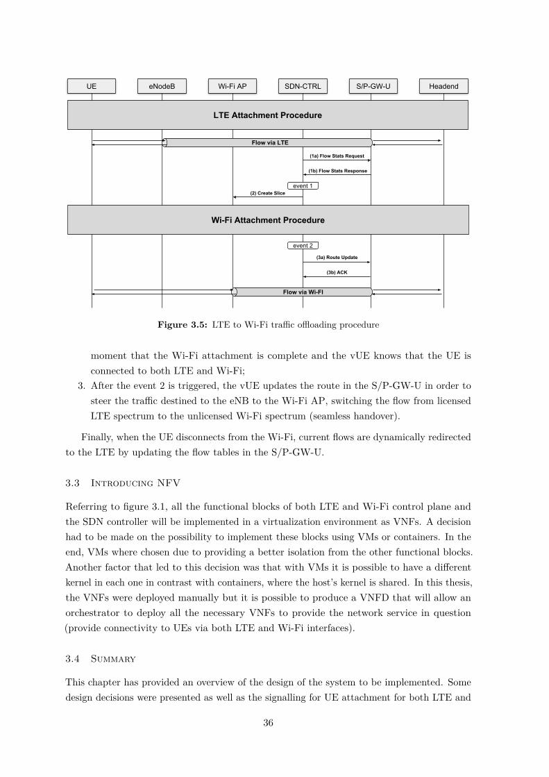
UE eNodeB Wi-Fi AP SDN-CTRL S/P-GW-U Headend
Flow via LTE
event 1
LTE Attachment Procedure
Wi-Fi Attachment Procedure
event 2
Flow via Wi-FI
(1a) Flow Stats Request
(1b) Flow Stats Response
(2) Create Slice
(3a) Route Update
(3b) ACK
Figure 3.5: LTE to Wi-Fi traffic offloading procedure
moment that the Wi-Fi attachment is complete and the vUE knows that the UE isconnected to both LTE and Wi-Fi;
3. After the event 2 is triggered, the vUE updates the route in the S/P-GW-U in order tosteer the traffic destined to the eNB to the Wi-Fi AP, switching the flow from licensedLTE spectrum to the unlicensed Wi-Fi spectrum (seamless handover).
Finally, when the UE disconnects from the Wi-Fi, current flows are dynamically redirectedto the LTE by updating the flow tables in the S/P-GW-U.
3.3 Introducing NFV
Referring to figure 3.1, all the functional blocks of both LTE and Wi-Fi control plane andthe SDN controller will be implemented in a virtualization environment as VNFs. A decisionhad to be made on the possibility to implement these blocks using VMs or containers. In theend, VMs where chosen due to providing a better isolation from the other functional blocks.Another factor that led to this decision was that with VMs it is possible to have a differentkernel in each one in contrast with containers, where the host’s kernel is shared. In this thesis,the VNFs were deployed manually but it is possible to produce a VNFD that will allow anorchestrator to deploy all the necessary VNFs to provide the network service in question(provide connectivity to UEs via both LTE and Wi-Fi interfaces).
3.4 Summary
This chapter has provided an overview of the design of the system to be implemented. Somedesign decisions were presented as well as the signalling for UE attachment for both LTE and
36

Wi-Fi and for LTE to Wi-Fi traffic offloading. The next chapter presents a more detailedinsight of each of the functional blocks by presented the implementation details.
37


CHAPTER 4Solution Implementation
The following chapter presents implementation details for the proposed architecture as well asthe tools used to implement the various functional blocks during the execution of this thesis.
4.1 Overview
Figure 4.1 illustrates the implementation of each functional block in the datacenter as wellas the virtual networks that were created. The VIM used for the cloud environment was
Radio Access Network (RAN)
Datacenter (Core Network)
External Networks/Operator Services
eNB
LTE-Uu
UE
WI-FI AP
Wi-Fi
External Network
CP Internal Network
S/P-GW-U
AAADHCP Server
HSS+MME
S/P-GW-C
oai-spgwRyu SDN CTRL
isc-dhcp-server OVS
Wi-Fi SDN Interface
freeradius-server
diameter-agent OVS OVSDBoai-mmeoai-hss
openairinterface5g
hostapd OVS
SGi-LTE Network
SGi-Wi-Fi NetworkvRouter
SGi
vUE Context Updater
Figure 4.1: Architecture implementation in Openstack cloud environment
Openstack1. Openstack has caught the attention of mobile operators and it is becoming the1Openstack: https://www.openstack.org/
39

de-facto standard for the VIM in telecommunication networks using NFV. Besides, Openstackwas the VIM already deployed at our in-house datacenter at the Instituto de Telecomunicações,Telecommunications and Networks group2.
4.1.1 Virtual Networks and Interfaces
Looking at figure 4.1, we can identify 4 Openstack virtual networks. The External Network isconnected to the physical network outside Openstack and it is the network where VMs areconnected in order to access external networks. The CP Internal Network was created and itis the virtual network that will carry the control plane traffic between each of the functionalblocks (i.e., VMs). Finally, we can identify the SGi-LTE Network and the SGi-Wi-Fi Network.These networks are used to carry data plane traffic and are presented in more detail in section4.5. By default, the Openstack security groups block all inbound packets towards the VMs.For that fact, security group rules had to be defined to allow inbound protocols such as UDP,TCP, SCTP (IP protocol 132) and GRE (IP protocol 47). In addition to the protocols usedby the interfaces described in sections 2.1.7 and 2.2.1, table 4.1 presents the protocols used ineach of the architecture specific interfaces.
Protocol InterfaceREST LTE Northbound Interface
Wi-Fi Northbound InterfaceOpenflow 1.3 CP Southbound Interface
Wi-Fi CP Southbound InterfaceOVSDB MP Southbound InterfaceUDP SDN-InfoDHCP STa-DHCP
Table 4.1: Protocols used by the architecture specific interfaces
4.1.2 Virtual Machine (VM) Specifications
Looking at figure 4.1, each one of the blocks inside the datacenter represents a VM. Theresources attributed to each VM, their Operating System (OS) and kernel version are presentedin table 4.2.
VM #CPUs RAM (GB) OS KernelHSS+MME 1 2 Ubuntu Server 16.04 LTS 4.4.0-121-lowlatencyS/P-GW-C 1 2 Ubuntu Server 16.04 LTS 4.4.0-121-lowlatencyAAA 1 2 Ubuntu Server 16.04 LTS 4.4.0-121-lowlatencyDHCPServer
1 2 Ubuntu Server 16.04 LTS 4.4.0-121-lowlatency
S/P-GW-U 2 4 Ubuntu Server 16.04 LTS 4.3.6-040306-lowlatency
Table 4.2: Resources used by the architecture’s VMs
2Telecommunications and Networks group: http://www.it.pt/tn-av
40

4.2 Radio Access Network (RAN)
The RAN, formed by the eNB in the 3GPP RAN and by the Wi-Fi AP in the non-3GPPRAN is the interface between the air interface and the core network. The implementation ofthese two RAN components is presented in the following subsections.
4.2.1 Evolved NodeB (eNB)
To implement the eNB the open-source project Openairinterface5g3 was used. This projectimplements a fully 3GPP compliant eNB and it can be deployed using SDR boards andgeneral purpose hardware.
4.2.1.1 Hardware Setup
Figure 4.2 presents a scheme of the hardware used for the eNB deployment. For the antenna,a LP0965 antenna4 was used. In order to allow the use of only one antenna, i.e., the sameantenna sending and receiving data, a band 7 duplexer5 was used. As for the SDR board, anUSRP B2106 was used and it was connected to the desktop via Universal Serial Bus (USB)3.0. The desktop used was a HP Z240 tower equipped with an Intel Core i7-7700-K (4 Cores)and 32 GB RAM. The connections between the antenna, the duplexer and the SDR boardwhere made with SMA-SMA semi-rigid RG402 coaxial cables. Because the eNB needs to
SDR BoardDuplexer DesktopAntenna USB 3.0 S1-MME/S1-U
Figure 4.2: eNB Implementation Scheme
perform real time functions, the desktop needs to be configured accordingly. First, the UbuntuDesktop 16.04.4 LTS was installed with the 4.4.0-124-lowlatency kernel. Then, in the system’sBasic Input/Output System (BIOS), all power management features were disabled (sleepstates and c-states) as well as CPU frequency scaling. Also, hyperthreading was disabledin the BIOS. After the BIOS is properly configured, the kernel needs to be configured todisable c-states and p-states and to set the governor to performance. All these configurationsforce the CPU to be at it’s maximum frequency all the time thus reducing the response timecompared with a situation in which the frequency had to be raised on demand. This way, theCPU is as responsive as possible.
4.2.1.2 Open Air Interface (OAI) Software Setup
To implement the eNB, the master branch of the openairinterface5g project was used. Theinstallation process starts with cloning the git repository to the eNB machine (Desktop in
3Openairinterface5g: https://gitlab.eurecom.fr/oai/openairinterface5g4LP0965 Antenna: https://www.ettus.com/product/details/LP09655Band 7 Duplexer: https://open-cells.com/index.php/opencellsband7duplexer/6USRP B210: https://www.ettus.com/product/details/UB210-KIT
41

figure 4.2). The repository includes automated scripts to install the necessary dependenciesand to compile the code itself. Using these scripts the OAI eNB, called lte-softmodem, isinstalled. The next step is to configure it using one of the sample configuration files. Thesefiles contain several configuration parameters. The most relevant are presented in table 4.3.Also, in this configuration file, the MME IP address is defined as well as the network interfaces
Parameter ValueTracking Area Code (TAC) 1Mobile Country Code (MCC) 208Mobile Network Code (MNC) 93Frame Type FDDEvolved Universal Terrestrial Radio Access (EUTRA) band 7 (2.6 GHz)Bandwidth 20 MHz (100 Physical Re-
source Blocks (PRBs))
Table 4.3: eNB Configuration
to be used for both the S1-MME and the S1-U interfaces.
4.2.2 Wi-Fi Access Point (AP)
The Wi-Fi AP is intended to behave as an operator AP. For the deployment of the Wi-Fi APa PC Engines apu2c47 was used with a wle600vx8 network card connected via mini PeripheralComponent Interconnect (PCI). This machine has an AMD GX-412TC CPU and 4 GB RAM.In this system, the Ubuntu server 14.04.5 LTS was installed with the 4.4.0-31-generic kernel.Figure 4.3 illustrates the various functional blocks and how they interconnect inside the AP.First, OVS 2.9.90 was installed in the machine and an OVS bridge was created (br0). Then,
Hostapd isc-dhcp-relay
br0(OVS)
STa/S2aWi-Fi CP Southbound Interfaceeth0
gre0
gre-dhcp
dhcp
-tap
wlan0
Figure 4.3: Wi-Fi AP architecture
the physical port eth0 was added to the bridge. To maintain connectivity in this physical port,the MAC and IP addresses of the eth0 interface was configured as the MAC and IP addressesof br0. Also, br0 was configured as the gateway interface for this machine forcing all packets
7APU: https://www.pcengines.ch/apu2c4.htm8wle600vx Network Card: https://www.pcengines.ch/wle600vx.htm
42

leaving or arriving to the system to pass through br0. Two GRE vPorts were also created:gre0 and gre-dhcp, where gre0, configured with the remote IP address of the S/P-GW-U, is atunnel port that will carry data plane traffic for the connected UEs to the Wi-Fi interface,and gre-dhcp, which is configured with the remote IP of the DHCP Server, will be used toreceive DHCP offers from the DHCP server. Furthermore, vPort dhcp-tap is added to br0and it will be used to send DHCP offers and acknowledgements to the DHCP relay. Finally,br0 is configured to be controlled by the SDN controller residing in the VM S/P-GW-C. Tosetup this machine as a Wi-Fi AP, Host access point daemon (Hostapd)9 version 2.1 wasinstalled. This user space software is capable of turning normal network interface cards intoaccess points and authentication servers. After installation, Hostapd was configured to usewlan0 (the network interface for the wireless network card) as the wireless interface and toperform authentication via a remote RADIUS authentication server (the AAA server). Thehostapd was configured to use the 802.11g protocol that uses a radio frequency of 2.4 GHz.When a user tries to attach to the Wi-Fi network, the authentication packets travel fromthe wlan0 interface to the default gateway interface, i.e., br0, which forwards the packetstowards the AAA server. The returning packets are then forwarded to the wlan0. Afterthe L2 attachment procedure is complete, the L3 attachment starts with a DHCP discover.DHCP packets are broadcast packets and, since there is already a DHCP server present inthe network which the AP is connected, a DHCP relay had to be used to relay the DHCPpackets between the wlan0 interface and the VM with the DHCP server. The relay used wasthe isc-dhcp-relay10 daemon. The DHCP relay was configured to listen to the wlan0 anddhcp-tap interfaces and with the IP address of the DHCP server’s VM. When the relay getsa broadcast DHCP packet it relays it to the DHCP server which means that the packet is nolonger a broadcast packet. The DHCP responses from the server are received in the gre-dhcpinterface and are forwarded to the dhcp-tap interface and consequently to the wlan0 interface.After the attachment is complete, the UE’s packets start flowing from the wlan0 interfaceto the gateway interface (br0). This bridge will receive flow configurations from the SDNcontroller in order to forward UE packets from the wlan0 to the gre0 interface and vice versa.
4.2.3 UE Setup
In order to connect an UE to the proposed architecture, a programmable USIM card is required.The programmable USIM used was a sysmocom’s sysmoUSIM-SJS111. To program the USIMcard the Gemalto IDBridge K3012 programmer was used. The software used to program theUSIM card was pcscd13 and pysim14. When the UE is configured with information compatiblewith the information in table 4.3, the UE is ready to connect to the network. Despite beingable to connect to the network, further configurations must be done in the UE for it to beable to access the internet. One of which is to define an APN. Table 4.4 summarizes the
9Hostapd: https://wiki.gentoo.org/wiki/Hostapd10dhcrelay: http://manpages.ubuntu.com/manpages/xenial/man8/dhcrelay.8.html11USIM Card: http://shop.sysmocom.de/products/sysmousim-sjs1-4ff12USIM Card Programmer: http://www.cryptoshop.com/gemalto-idbridge-k30-usb-shell-token-v2.html13PCSCD: https://linux.die.net/man/8/pcscd14pysim: https://github.com/osmocom/pysim
43

relevant APN information configured in the UE. After setting the APN it is possible to use
Parameter ValueAPN oai.ipv4APN protocol IPv4Bearer LTEMCC 208MNC 93
Table 4.4: UE APN configuration
mobile data to access the internet.Because the MTU of the network that connects the eNB to the datacenter (our facilities
network) was of 1500 bytes and the default MTU of the UE is also 1500 bytes, packets with asize of over 1450 bytes would be lost. That happened because the packets that travel betweenthe eNB and the S/P-GW-U at the datacenter are encapsulated in a GTP tunnel which addsa 50 bytes header to the packet. This causes the packets with size over 1450 bytes to befragmented and, because UDP has no packet reassembly capabilities, the received packet sizeand the size indicated in the packet’s headers differed, causing the packet to be dropped. Inorder to solve this issue, and knowing that increasing the MTU of our facility’s network wasnot an option since it required the reconfiguration of several pieces of equipment, the onlyoption was to lower the MTU of the UE’s LTE interface. However, Android (the UE OSused in the execution of this thesis) does not allow this interface configuration with a stocksystem. So, in order to lower the UE’s MTU the UE had to be rooted, allowing the access tothe network interfaces. Then, using a terminal emulator for Android, the MTU of the LTEinterface was lowered and the UE accessed the Internet without packet losses due to packetfragmentation.
4.3 LTE Control Plane
The LTE control plane includes all the necessary functional blocks to control the variousnetwork components of the EPC. An implementation description is now provided.
4.3.1 HSS+MME
This functional entity (VM) incorporates two network functions: HSS and MME. Figure4.4 illustrates the internal architecture of the HSS+MME VM. The MME connects tothe HSS through the localhost interface. Both of these functions where developed in theopenair-cn15 project. The MME was installed as is from the git repository. Similarly to theopenairinterface5g project, this project also provides some automated installation scripts. Theinstallation of the MME starts with the installation of the required dependencies. After that,the code was compiled and installed and the MME was configured with the IP address ofthe S/P-GW-C. When it comes to the HSS it could not be installed as cloned from the git
15openair-cn: https://gitlab.eurecom.fr/oai/openair-cn
44

HSS+MME
oai-mme oai-hss
CP
Inte
rnal
Net
wor
k
Ext
erna
l Net
wor
k
localhost
Figure 4.4: HSS+MME Architecture
repository since it did not support the SWx interface so, support for this interface had tobe added. The HSS uses freeDIAMETER16, an open-source project implementation of theDIAMETER base protocol. In this project, new applications and their AVPs are defined asdictionaries. Since the base freeDIAMETER does not include support for the S6a interface,OAI implemented the S6a dictionary and changed the diameter base code via a patch. Thesame method was used during the execution of this thesis, where the SWx interface dictionarywas defined following the 3GPP specifications [17] and a patch was produced. Then, the OAIHSS source code was modified by duplicating the S6a lines but using the SWx parametersand freeDIAMETER dictionary instead. Regarding to user subscription data, the HSS usesMySQL17 databases.
4.3.2 S/P-GW-C
The S/P-GW-C VM is composed by the OAI S/P-GW and an SDN controller (RYU SDNController). These two modules run in the same VM but could also be separated intotwo distinct VMs, where there would be a slight increase in the LTE attachment time,corresponding to the additional time for the messages to travel between the two VMs. Figure4.5 illustrates the internal architecture of the S/P-GW-C VM. The following subsectionspresent implementation details for both the OAI S/P-GW and the SDN controller.
S/P-GW-C
SDN Controller oai-spgw
CP
Inte
rnal
Net
wor
k
Ext
erna
l Net
wor
k localhost
Figure 4.5: S/P-GW-C Architecture
4.3.2.1 S/P-GW
The OAI S/P-GW source code had to be changed in order to send a REST command to theSDN controller instead of trying to create a tunnel in the VM’s kernel. In order to achievethis, a new module (the sdn_rest) was implemented and integrated into the source code. This
16freeDiameter: http://www.freediameter.net17MySQL: https://www.mysql.com/
45

module was written in C and it is composed by two files: sdn_rest.c and sdn_rest.h. Theheader file defines a structure to pass the UE information to the thread that will send theREST command to the SDN controller. The structure, called ue_info, contains the followingUE information:
• User’s IMSI;• UE IP address;• eNB IP address;• eNB S1-U TEID;• S/P-GW S1-U TEID.
Regarding to the sdn_rest.c file, it contains the definition of three functions:• create_gtpv1u_tunnel;• delete_gtpv1u_tunnel;• curl_post_data;
The curl_post_data function receives information from the two other functions in the form oftwo strings: one string with the Uniform Resource Identifier (URI) of the SDN controller andanother string with the information to be sent. The URI, depending if the UE is attaching ordetaching from the network, can be:
• http://<SDN controller IP>:8080/spgw/ue/lte/add• http://<SDN controller IP>:8080/spgw/ue/lte/delete
After receiving this information, the function sends it via a REST message to the SDNcontroller. The create_gtpv1u_tunnel and the delete_gtpv1u_tunnel functions were definedas shown in appendix A, section "sdn_rest module". For the create method all the informationcontained in the ue_info structure is needed. On the other hand, for the delete method onlythe IMSI is required.
After the sdn_rest module was integrated in the openair-cn source code, the source codeof the OAI S/P-GW had to be changed to use the newly implemented module. That was donein the sgw_handlers.c file. The changes made to the sgw_handlers.c file are represented inappendix A, section "modifications to the sgw_handlers.c file". The same approach was usedin the function where the GTP tunnel is removed. In addition to the source code changes,the Makefile had to changed also in order to properly compile the newly implemented moduleand to use the required libraries (the sdn_rest module requires the libcurl18 library). Withthese changes, the OAI S/P-GW runs as an SDN application (i.e., it runs on the applicationplane presented in section 2.4.3).
Figures 4.6 and 4.7 represent the behaviour of the modified functions working togetherwith the sdn_rest module during attachment and detachment, respectively. The figures onlyrepresent the behaviour of the method that replaces the tunnel creation in the VM’s kernel.
18libcurl: https://curl.haxx.se/libcurl/
46

sgw_handle_sgi_endpoint_updated create_gtpv1u_tunnel
Fill in the ue_info structure
Create “create_gtp_tunnel” Thread with ue_info
(args)
Start ThreadError
creating thread?
Extract ue_info from args
Build URI string (spgw/ue/lte/add)
Build info string
Send REST to SDN ControllerPrint error message
YES
NO
Figure 4.6: Modified function behaviour during attachment
sgw_handle_sgi_endpoint_deleted delete_gtpv1u_tunnel
Fill in the ue_info structure
Create “delete_gtp_tunnel” Thread with ue_info
(IMSI)
Start ThreadError
creating thread?
Extract IMSI from args
Build URI string (spgw/ue/lte/delete)
Build info string
Send REST to SDN ControllerPrint error message
YES
NO
Figure 4.7: Modified function behaviour during detachment
47

4.3.2.2 SDN Controller
The SDN controller was based on the RYU SDN controller. A specific controller application,written in python, was developed to control the OVS switches contained in the proposedsystem. The controller application is divided into two parts: one that acts as a virtualizationof the UE (vUE) and another part that is responsible for the traffic offloading. The trafficoffloading part of the application was jointly developed with an on-going PhD thesis. Theoverall application, can be decomposed into three major behaviours:
• REST command handling;• UE context handling and Flow handling (CP);• OVS port handling (MP);
When the controller starts running and an OVS switch connects to it, the Datapath Identifier(DPID) is exchanged. The DPID is the identification of the OVS switch and it is preconfigured.The flowchart from figure 4.8 represents how the controller handles the initial connection ofan OVS switch. A description of the source code can be found in appendix B. This function
OVS Switch Connects
Install SPGW Default Flows
YES
NO
DPID equal to SPGW_DPID?
DPID equal to WIFI_AP_DPID?
Send Retrieve Port list command
Install WIFI AP Default Flows
DPID equal to DHCP_DPID?
Install DHCP Server Default Flows
Unrecognized Datapath
YES
YES
NO
NO
Figure 4.8: SDN controller behaviour during initial OVS switch connection.
installs the default flows in each one of the OVS switches present in the system at the time theyconnect to the controller. The DPID of each OVS switch is pre-configured in the controller’sconfiguration file. Looking at figure 4.8 we can see that, when the S/P-GW-U OVS switchconnects to the controller, the controller issues a command to retrieve a list of ports of theswitch. A python dictionary was defined to hold information about the switches’ ports wherethe key is the port name and the corresponding value is the port number. Figure 4.9 illustratesthe behaviour of the function that is called when the switch answers with its ports. The
48

function goes through all the ports contained in the message and it fills the dictionary withthe received ports. Also related to switch port management, a function is defined and called
Received SPGW port list
NO
Retrieve port from message
Save port to ports dictionary
Message contains more
ports?
YES
Stop
Figure 4.9: Behaviour of the Port Description Reply handler
whenever a port in the switch is created or deleted. The function then adds or deletes theport in the ports dictionary. Figure 4.10 represents the behaviour of the function. Refer toappendix B for the function’s implementation.
Received Port Event
NO
Save port to ports dictionary
A port was added?
YES
Delete port from ports dictionary
A port was deleted?
YES
Exit
Figure 4.10: Behaviour of the handler for the port modification event
Regarding to the UE context, a structure was created to define an UE. This structure wascalled mobileNode, it holds information about UEs and it has functions related to the UE(add or delete UE flows, add or delete ports). The mobileNode structure holds the followinginformation:
49

• IMSI (parameter common to both LTE and Wi-Fi access;• IP address of the LTE interface;• eNB TEID;• S-GW TEID;• eNB IP address;• GTP port number;• IP address of the Wi-Fi interface;• TEID (in this implementation the remote TEID is the same as the local TEID for
Wi-Fi);• Wi-Fi AP IP address;• GRE port number.
With this structure defined, a python dictionary is created in order to hold the context ofUEs attached to the network via LTE and/or Wi-Fi. The name given to the dictionary wasmobile_nodes, with the key being the user’s IMSI and the value is the mobileNode structure.Then, the handler functions for the REST commands are defined and their behaviour isshown in figures 4.11 and 4.12. Figure 4.11 illustrates the behaviour of the controller when itreceives a /spgw/ue/lte/add or /spgw/ue/wifi/add command while figure 4.12 illustrates thebehaviour of the controller when it receives a /spgw/ue/lte/delete or a /spgw/ue/wifi/deletecommand (refer to appendix B for the pseudo source code). When the /spgw/ue/lte/add or
Received REST Message
NO
UE Already Connected
through LTE/Wi-Fi?
YES
Retrieve parameters from message
Load mobileNode structure
Register LTE/Wi-Fi
Create mobileNode structure
Save mobileNode in mobile_nodes
Figure 4.11: REST message handler for the attachment of UEs
/spgw/ue/wifi/add REST message is received, the controller application checks if the UE is
50

already connected to the other available access technology (Wi-Fi if the UE is attachmentto LTE or LTE if the UE is attaching to the Wi-Fi interface). It then creates or loads themobileNode structure for this UE and calls the register LTE or register Wi-Fi functions,depending on the interface that the UE is attaching. The behaviour of the register LTE and
Received REST Message
NO
UE is Connected?
YES
Retrieve parameters from message
Load mobileNode structure
Unregister LTE/Wi-Fi
Exit
UE is Connected to
LTE/Wi-Fi?
Delete mobileNode from mobile_nodes
NO
YES
Figure 4.12: REST message handler for the detachment of UEs
register Wi-Fi functions is depicted in figures 4.13 and 4.14 respectively. Both these functionshave a similar behaviour with the exception that the function to register the Wi-Fi client inaddition of the flows that it installs in the S/P-GW-U, it also installs flows in the Wi-Fi AP.These functions verify if the required GTP or GRE tunnel ports are already created (i.e., arepresent in the ports dictionary) and, if the ports are not found, the controller creates the portsin the switch, waiting for the required ports to be available in the ports dictionary. Afterthe port is created, the necessary flows are installed via OpenFlow (OF) flow modificationmessages. For the detachment process, called unregister LTE or Wi-Fi in the context ofthe SDN controller, the behaviour of the unregister functions for both LTE and Wi-Fi aredepicted in figures 4.15 and 4.16 respectively.
Regarding to the context updater, the controller application is responsible for the trafficoffloading and for the trigger for the slice creation. The offloading process is divided in fourstages.
1. The vUE detects that a given link quality threshold was reached. For this the OF flowstats message (sent by the controller to the S/P-GW-U with a periodicity of 5s) was
51

Register LTE
NO
Does ports contain this GTP port?
YES
Set mobileNode LTE Variables
Set GTP port number in mobileNode
variable
Install Uplink and Downlink Flows in
S/P-GW-U
Create GTP Port
Does ports contain this GTP port?
YES
NO
Figure 4.13: Behaviour of the Register LTE function
Register Wi-Fi
NO
Does ports contain this GRE port?
YES
Set mobileNode Wi-Fi Variables
Set GRE port number in mobileNode
variable
Install Uplink and Downlink Flows in
S/P-GW-U
Create GRE Port
Does ports contain this GRE port?
YES
NO
Install Uplink and Downlink Flows in
Wi-Fi AP
Figure 4.14: Behaviour of the Register Wi-Fi function
52

unregister LTE
Delete Uplink and Downlink Flows in
S/P-GW-U
Reset mobileNode LTE IP variable
Figure 4.15: Behaviour of the Unregister LTE function
Unregister Wi-Fi
Delete Uplink and Downlink Flows in
S/P-GW-U
Delete Uplink and Downlink Flows in
Wi-Fi AP
Reset mobileNode Wi-Fi IP variable
Figure 4.16: Behaviour of the Unegister Wi-Fi function
used to analyse the characteristics of the user’s flow (e.g., protocol, port and bitrate). Ifsuch analysis results in an offloading decision, the vUE requests the slice creation;
2. The slice is created exploiting hostapd features by instantiating a specific SSID for theUE, whose authentication is performed using EAP-AKA;
3. The UE detects the SSID and attaches to it;4. The vUE implements a flow redirection in the S/P-GW-U via an OF flow modification
message.The context updater application also receives the Register LTE and Register Wi-Fi but
treats them differently. The behaviour of the application when it receives the Register LTEmessage is depicted in figure 4.17. This part of the application is responsible for analysingthe user’s traffic flows and trigger the slice creation. The application periodically requests tothe S/P-GW-U information about it’s flows.
When the application receives the Register Wi-Fi message, it verifies if the UE is alsoconnected via LTE and it installs downlink offloading flows via an OF flow modificationmessage. These flows have a higher priority than the existing flows installed by the vUE. On
53

Register LTE
NOFlow analysis
results in offloading decision?
YES
Send Flow Stats Request
Send Slice creation message to Wi-Fi AP
Get Flow Stats Response and analyse flows
Wait 5s
Figure 4.17: Trigger behaviour for the Slice Creation Process
the other hand, when the context updater receives an Unregister Wi-Fi message, it deletesthe offloading flows, also via an OF flow modification message. This behaviour is depicted infigure 4.18.
Register Wi-Fi
Install Downlink Offloading flows
Unregister Wi-Fi
Delete Downlink Offloading flows
Is the user connected to
LTE?
Do nothing
NOYES
Figure 4.18: Behaviour of the context updater when a user connects to Wi-Fi when it is also connectedto LTE
Finally, regarding to SDN planes, the functions related with GTP and GRE port creationbelongs to the MP and all the other functions belong to the CP.
4.4 Wi-Fi Control Plane
The Wi-Fi control plane is composed by, at the EPC, the AAA server and by the DHCPserver. The AAA server is one of the components involved in the L2 attachment and theDHCP server is involved in the L3 attachment of UEs.
54

4.4.1 Authentication, Authorization and Accounting (AAA)
The AAA server is responsible for the authentication of users trying to connect to the Wi-Finetwork. It is composed by the RADIUS server and a diameter-agent as shown in figure4.19. For the AAA server the FreeRADIUS server19 open-source project version 4.0 was
AAA Server
RADIUS Server diameter-agent
CP
Inte
rnal
Net
wor
k
Ext
erna
l Net
wor
k localhost
Figure 4.19: AAA Server Architecture
used. This RADIUS server implements a multi-protocol policy server which includes theEAP-AKA protocol. However, at the time of this writing, the EAP-AKA module did notwork as expected for two major reasons: first, the EAP-AKA authentication vector had to bedefined manually in a configuration file, including the Sequence Number (SQN) parameter.Because the SQN number changes every time the UE attaches to the network this methodcannot be used. The second reason was that it did not have a method to fetch the EAP-AKAkeys from another entity. In order to use the freeRADIUS server, some modifications toits source code were made. Looking at figure 4.1, in the AAA functional block we can seethat there are two modules defined. One is the freeRADIUS server already mentioned. Theother is the diameter-agent. This diameter-agent entity implements the SWx interface in theAAA using freeDIAMETER. The interaction between the two modules is performed usingUDP messages where there is one type of message when the RADIUS server is requesting theEAP-AKA authentication vector and another type when the diameter-agent is providing theEAP-AKA authentication vector to the RADIUS server. The request UDP message has apayload of 15 bytes and contains the user’s IMSI. The response message has a payload of 72bytes and it contains the following values: RAND, AUTN, XRES, CK and IK. The followingsubsections describe in detail the changes performed to the freeRADIUS source code and theimplementation of the diameter-agent.
4.4.1.1 RADIUS server
In the RADIUS server, the function that obtains the EAP-AKA authentication vector isthe vector_umts_from_ki function, located in the src/modules/rlm_eap/lib/sim/vector.cfile. The function was completely changed and a description of its behaviour is providedin figure 4.20. Also, appendix C presents a description of the source code of this function.With this modification to the source code, the freeRADIUS server is now able to fetch theEAP-AKA authentication vector from an external entity and to provide information to theDHCP server that enables it to associate the MAC address of an UE Wi-Fi interface to theuser’s IMSI and to the Wi-Fi AP where the UE is connected. The next step is to implement
19FreeRADIUS: https://freeradius.org/
55

Extract UE MAC address from received args
Extract Wi-Fi AP IP address from received args
Send IMSI, UE MAC Address and Wi-Fi AP
IP to DHCP Server
Send IMSI to diameter-agent
Wait for an answer
Extract Authentication Vector
from received message
Set the keys variable with the
authentication vector
Return
Figure 4.20: Behaviour of the modified function
the diameter-agent itself so that it can translate the UDP message into the diameter messageto be sent to the HSS through the SWx interface as well as translate the diameter messageinto an UDP message.
4.4.1.2 Diameter Agent
The diameter_agent.c file holds the code for the diameter-agent. This agent was written inC and it uses the freeDIAMETER open-source project to build the DIAMETER messages.Similarly to what was described in the HSS implementation, a DIAMETER dictionary had tobe defined for the SWx interface. This dictionary followed the 3GPP standards [17] and thedictionary was added to the freeDIAMETER source code through a patch. The behaviour ofthe diameter-agent is depicted in figure 4.21. The diameter-agent was programmed followingthe OAI’s implementation of the S6a interface. After implementing the diameter-agent, aMakefile was produced to compile the code and use the libraries required by freeDIAMETER(fdcore and fdproto). The AAA server is now able to properly perform EAP-AKA basedauthentication by retrieving the authentication vector from the HSS.
56

Build Multimedia-Auth Request Message
Send Message to HSS
Extract the authentication vector
from the AVPs
Build UDP message with the
authentication vector
Send UDP message to RADIUS Server
Received IMSIReceived
Answer from HSS
Figure 4.21: Behaviour of the diameter-agent
4.4.2 DHCP Server
The DHCP server VM is composed by the isc-dhcp-server20, by an OVS switch and bya newly implemented module called Wi-Fi SDN Interface as illustrated in figure 4.1. Anarchitectural view of the DHCP server is provided in figure 4.22. The following subsections
DHCP Server
isc-dhcp-server Wi-Fi SDN IF
br0(OVS)
gre0
dhcp
-por
t
Leases FileC
P In
tern
al N
etw
ork
Ext
erna
l Net
wor
k
SDN Controller Interface
Figure 4.22: DHCP Server Architecture
present implementation details related to the OVS switch installation and configuration andto the Wi-Fi SDN interface developed during the course of this thesis.
4.4.2.1 OVS Setup
The OVS installed in the DHCP server was OVS 2.9. Before compiling and installing thesource code, the required packages were installed. Then the source code was compiled andinstalled. OVS uses kernel modules that are required when using tunnels. The kernel moduleswere successfully compiled however, the kernel modules failed to load in the VM. This
20DHCP Server: https://help.ubuntu.com/community/isc-dhcp-server
57

happened because the modules are installed in the extra subdirectory within /lib/moduleswhich is a directory that, by default, the system does not search when searching for kernelmodules. In order to solve that problem, the Ubuntu depmod configuration file had to bemodified in order to force the kernel to also search for kernel modules in the extra subdirectorywithin /lib/modules. After rebooting the VM, the kernel modules loaded as expected. Then,two vPorts are created in the switch: one is a GRE port that will carry the DHCP messagesleaving the DHCP server towards the Wi-Fi AP. The other port is the dhcp-port which is theport used by the isc-dhcp-server to send the DHCP messages to the bridge to be forwardedto the GRE tunnel port. After installation and port setup, the switch is then connected tothe SDN controller that will install the default flows in it. The processing of DHCP packetsin the OVS bridge is illustrated in the packet processing pipeline of figure 4.23.
Table 0
Priority Match5 in_port=dhcp_port,ip,ipv4_dst=<IP of Wi-Fi AP wlan0 if> set_field:<teid>->tun_id,output:gre0
Actions
Figure 4.23: Packet Processing Pipeline in the DHCP Server OVS switch
4.4.2.2 Wi-Fi SDN Interface
In order to send REST commands to the SDN controller whenever a UE attaches to thenetwork using Wi-Fi, the Wi-Fi SDN Interface was implemented and it executes in parallelwith the isc-dhcp-server. This module opens an UDP socket to receive UE information fromthe AAA server and it periodically verifies the isc-dhcp-server lease file to identify newlyconnected UEs in the network. When a new UE is detected, this module sends a RESTcommand to the SDN controller with the UE information (refer to section 3.2.3.1 for theattachment procedure). These commands take the following form depending if the UE isattaching or detaching from the network respectively:
• http://<SDN controller IP>:8080/spgw/ue/wifi/add• http://<SDN controller IP>:8080/spgw/ue/wifi/delete
The behaviour of this module, written in python, is illustrated in figure 4.24 and a descriptionof the source code can be found in appendix D. This module is responsible to inform the SDNcontroller that an UE has successfully attached to the network or detached from the network,allowing it to properly setup the data plane for this UE.
58

Read DHCP leases file
Compare the leases with the previous
reading
Save current leases
New leases where added?
Leases where removed?
Get new DHCP Lease Build URI and data strings
Send REST /wifi/add Message to SDN
Controller
Remaining new leases?
Get removed DHCP Lease
Build URI and data strings
Send REST /wifi/delete Message
to SDN Controller
Remaining removed leases?
NO
NO
NO
YES
YES
Figure 4.24: Behaviour of the Wi-Fi SDN Interface module
4.5 Data Plane
In the present architecture, the data plane in the virtual EPC is composed by the S/P-GW-UVM, by the SGi-LTE and SGi-Wi-Fi virtual networks and by an Openstack vRouter. Figure4.25 illustrates the architecture of the data plane of the virtual EPC. The OVS switch insidethe S/P-GW-U VM is responsible for forwarding packets from a tunnel port to the vRouterand from the vRouter to a tunnel port. In its turn, the vRouter receives packets from theSGi-Wi-Fi and SGi-LTE interfaces, applies NAT to the packets and routes them to theirdestination. The SGi-Wi-Fi and SGi-LTE networks are intended to transport UE traffic forboth the UL and DL directions and the subnet network address is in the same range as theaddress range defined for the UEs IP addresses. By default, Openstack blocks packets fromthe created networks that have addresses that it does not recognize which means that packetsoriginating from UEs would be blocked in the internal Openstack networks. In order to solvethat problem, Allowed Address Pairs have to be defined in each of the ports connected to the
59

S/P-GW-U
OVSDB
spgw(OVS)
gtp0
CP
Inte
rnal
Net
wor
k
Ext
erna
l Net
wor
k
gre0
sgi
sgi-wifi
SG
i-LTE
Net
wor
k
SG
i-Wi-F
i Net
wor
k
vRouter
Figure 4.25: S/P-GW-U Architecture
network which means that the IP range defined for both LTE and Wi-Fi access was configuredto be allowed by the Openstack networks, enabling UE traffic to flow through the internalnetwork. The following subsections describe the implementation of this data plane.
4.5.1 S/P-GW-U
The S/P-GW-U data plane entity from figure 4.25 shows two functional blocks: OVSDB andspgw. Framing these entities into the SDN planes from section 2.4.3, spgw corresponds tothe Forwarding Plane while OVSDB corresponds to the Operational Plane. The OVSDB isintegrated with the OVS project and the two modules are installed simultaneously.
One of the features required by OVS for this implementation is its ability to handle GTPtunnels. However, OVS does not natively support GTP tunnelling neither is it a part of theupstream Linux kernel. In order to bypass this limitation a patch21 was used. This patchwas developed for OVS 2.5 and it implements the kernel datapath module required for GTPtunnelling.
Analysing table 4.2, the only VM that differs in its kernel version is the S/P-GW-U VM.That is due to the fact that OVS 2.5 requires a kernel version between 3.3 and 4.3 (including).For that reason, the kernel version 4.3 was selected for this VM. After the kernel was setupthe ubuntu depmod configuration file was modified, as stated in section 4.4.2.1, in order toallow the system to properly load the OVS kernel modules. After this step is completed therequired OVS packages were installed, the OVS 2.5 source code was compiled and installedand the kernel modules were loaded. A bridge named spgw is then created in OVS.
The VM’s sgi and sgi-wifi interfaces, connected respectively to the SGi-LTE and SGi-Wi-Finetworks, are added to spgw as OVS ports. After the required ports are added to the spgwbridge and the bridge is connected to the SDN controller, it is ready to handle UE packets.The gtp0 and gre0 ports are not created during the initial configuration process because they
21OVS GTP Patch: https://patchwork.ozlabs.org/patch/579431/
60
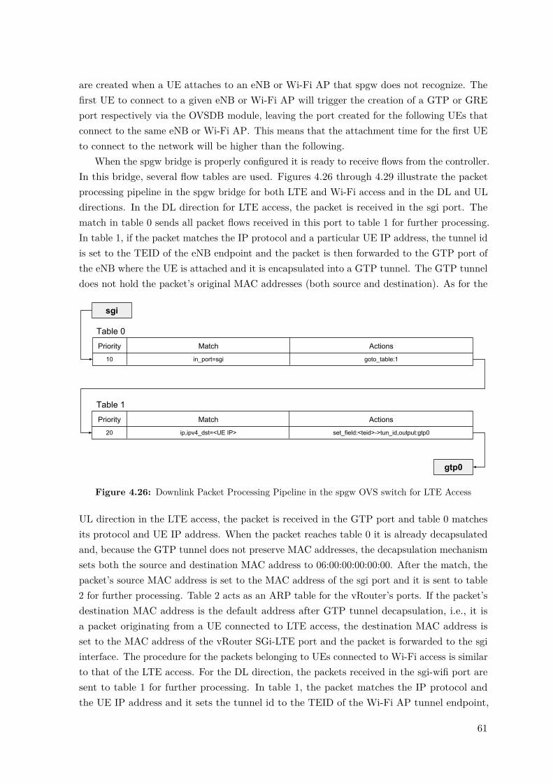
are created when a UE attaches to an eNB or Wi-Fi AP that spgw does not recognize. Thefirst UE to connect to a given eNB or Wi-Fi AP will trigger the creation of a GTP or GREport respectively via the OVSDB module, leaving the port created for the following UEs thatconnect to the same eNB or Wi-Fi AP. This means that the attachment time for the first UEto connect to the network will be higher than the following.
When the spgw bridge is properly configured it is ready to receive flows from the controller.In this bridge, several flow tables are used. Figures 4.26 through 4.29 illustrate the packetprocessing pipeline in the spgw bridge for both LTE and Wi-Fi access and in the DL and ULdirections. In the DL direction for LTE access, the packet is received in the sgi port. Thematch in table 0 sends all packet flows received in this port to table 1 for further processing.In table 1, if the packet matches the IP protocol and a particular UE IP address, the tunnel idis set to the TEID of the eNB endpoint and the packet is then forwarded to the GTP port ofthe eNB where the UE is attached and it is encapsulated into a GTP tunnel. The GTP tunneldoes not hold the packet’s original MAC addresses (both source and destination). As for the
Table 0
Priority Match
10 in_port=sgi goto_table:1
Actions
Table 1
Priority Match
20 ip,ipv4_dst=<UE IP> set_field:<teid>->tun_id,output:gtp0
Actions
sgi
gtp0
Figure 4.26: Downlink Packet Processing Pipeline in the spgw OVS switch for LTE Access
UL direction in the LTE access, the packet is received in the GTP port and table 0 matchesits protocol and UE IP address. When the packet reaches table 0 it is already decapsulatedand, because the GTP tunnel does not preserve MAC addresses, the decapsulation mechanismsets both the source and destination MAC address to 06:00:00:00:00:00. After the match, thepacket’s source MAC address is set to the MAC address of the sgi port and it is sent to table2 for further processing. Table 2 acts as an ARP table for the vRouter’s ports. If the packet’sdestination MAC address is the default address after GTP tunnel decapsulation, i.e., it isa packet originating from a UE connected to LTE access, the destination MAC address isset to the MAC address of the vRouter SGi-LTE port and the packet is forwarded to the sgiinterface. The procedure for the packets belonging to UEs connected to Wi-Fi access is similarto that of the LTE access. For the DL direction, the packets received in the sgi-wifi port aresent to table 1 for further processing. In table 1, the packet matches the IP protocol andthe UE IP address and it sets the tunnel id to the TEID of the Wi-Fi AP tunnel endpoint,
61

Table 0
Priority Match
10 ip,ipv4_src=<IP of UE> set_field:<MAC of sgi interface>->eth_src,goto_table:2
Actions
Table 2
Priority Match
10 eth_dst=06:00:00:00:00:00 set_field:<MAC of vRouter sgi-lte interface>->eth_dst,output:sgi
Actions
gtp0
sgi
Figure 4.27: Uplink Packet Processing Pipeline in the spgw OVS switch for LTE Access
forwarding the packet to the GRE port. As for the UL direction the packet received in the
Table 0
Priority Match
10 in_port=sgi-wifi goto_table:1
Actions
Table 1
Priority Match
20 ip,ipv4_dst=<UE IP> set_field:<teid>->tun_id,output:gre0
Actions
sgi-wifi
gre0
Figure 4.28: Downlink Packet Processing Pipeline in the spgw OVS switch for Wi-Fi Access
GRE port is matched against the protocol and the UE IP address, followed by setting thesource MAC address to the MAC address of the sgi-wifi interface. After that, the packet issent to table 2 for further processing. In table 2, the match for this packet is blank, meaningthat all packets that do not match the other flow entries are going to match this entry. Thelogic behind this implementation is that, in table 2, if a packet does not match the LTEdefault MAC address after GTP decapsulation it means that the packet belongs to a UEattached to the Wi-Fi access, leading to the setting of the destination MAC address of thepacket to the MAC address of the vRouter’s SGi-Wi-Fi port. After the packet modification,the packet is sent to the sgi-wifi port. This table setup with the specified flow entries allowthe S/P-GW-U to forward packets as needed.
When it comes to traffic offloading, a flow is installed that matches the IP address of theUE’s LTE interface, an IP protocol (e.g. UDP) and a port number. A packet processing
62

Table 0
Priority Match
10 ip,ipv4_src=<IP of UE> set_field:<MAC of sgi-wifi interface>->eth_src,goto_table:2
Actions
Table 2
Priority Match
10 set_field:<MAC of vRouter sgi-wifi interface>->eth_dst,output:sgi-wifi
Actions
gre0
sgi-wifi
Figure 4.29: Uplink Packet Processing Pipeline in the spgw OVS switch for Wi-Fi Access
pipeline example for offloading scenarios is depicted in figure 4.30. In this scenario, a flowentry is installed, with a higher priority than the entries already installed, that redirects UDPflows from a specific port from LTE to Wi-Fi. The flow entry in table 1, that is illustrated inthe figure, is the same that was installed earlier, so only one flow entry needs to be installedin the S/P-GW-U in order to offload traffic. In this implementation only downlink trafficoffloading is considered.
Table 0
Priority Match
100 in_port=sgi,udp,ipv4_dst=<UE LTE IP>,udp_dst=<port> set_field:<UE Wi-Fi IP>->ipv4_dst,goto_table:1
Actions
Table 1
Priority Match
20 ip,ipv4_dst=<UE Wi-Fi IP> set_field:<teid>->tun_id,output:gre0
Actions
sgi
gre0
Figure 4.30: Downlink Packet Processing Pipeline in the spgw OVS switch for the LTE to Wi-FiOffloading procedure
4.5.2 vRouter
The vRouter is an Openstack router and its functions are to perform source NAT and routepackets. It was connected to the external network as well as the SGi-LTE and SGi-Wi-Finetworks. In order to tell the router what to do with packets coming from external networks,two static routes were defined. The routes indicate the router that, when a received packet
63

(after the address is translated) is destined for an IP address in the range of the LTE assignedaddresses or in the range of the Wi-Fi assigned addresses, the IP address of the next hopwill be the IP address of the sgi or sgi-wifi interfaces respectively. This step concludes theimplementation of the datapath of the system.
4.6 Summary
This chapter presented implementation details of the proposed architecture. Although someof the elements were used as provided by the several open-source projects, the majority hadto be modified in order to be deployed in the data center, to incorporate SDN and to addsupport for Wi-Fi access. In the next chapter the proposed architecture is evaluated and theresults are presented.
64

CHAPTER 5Architecture Validation
This chapter presents the tests conducted in order to validate the architecture whose im-plementation was described in the previous chapter. The system was evaluated in terms ofattachment time, throughput and latency. These measurements will be compared againstthe vanilla OAI EPC (i.e., as clone from the project’s repository) deployed in a physicalmachine whenever possible. Finally, two use cases for this architecture are evaluated. All testspresented in this section were performed 10 times, with the results presenting their averagewith a confidence interval of 95 percent.
5.1 Signalling Impact
This section aims to study the size of the control messages in the implemented architectureand the impact they have in the control interfaces. To obtain the messages exchanged betweenentities, the tcpdump1 tool was used to capture packets at the control plane interfaces. TheUE attached to both LTE and Wi-Fi in order to generate the signalling messages was aSamsung Galaxy J5 2016 running Android 7.1.
5.1.1 3GPP Defined
First, the control messages defined by 3GPP are analysed. Table 5.1 presents the controlplane messages by interface and their respective size. Refer to sections 2.1.7 and 2.2.1 for theprotocol used by each of the interfaces.
1tcpdump: https://www.tcpdump.org/
65

Interface Message Size (bytes)S1-MME Attach Request, PDN Connectivity Request 210
Identity Request 110Identity Response 146Authentication Request 142Authentication Response 130Security Mode Command 122Security Mode Complete 134Attach Accept 278UE Capability Information 178Attach Complete 182SACK 62
S6a 3GPP Authentication Information Request 3383GPP Authentication Information Answer 3583GPP Update Location Request 3263GPP Update Location Answer 610
S11 Create Session Request 194Create Session Response 164Modify Bearer Request 85Modify Bearer Response 60
SWx Multimedia Auth Request 358Multimedia Auth Answer 422
STa Access Request 315Access Challenge 176Access Accept 255
Table 5.1: Size of the messages defined by 3GPP
5.1.2 Architecture Specific Interfaces
Some interfaces used in this architecture run out of the scope of 3GPP standards and areanalysed with some more detail in this section. Table 5.2 presents not only the size of themessages but also the size of the useful information they carry, i.e., the payload.
Interface Message Size (bytes) Payload (bytes)STa-DHCP DHCP Discover 348 305
DHCP Offer 385 300DHCP Request 360 317DHCP ACK 385 300
Northbound Interface Add LTE UE 301 97Add Wi-Fi UE 402 106200 OK 181 0
MP Southbound Interface Create Tunnel 21298 19131CP Southbound Interface Uplink Flows 170 104
Downlink Flows 178 112SDN Info Terminal Info 78 36
Table 5.2: Architecture Specific Interfaces and their size and payload
66

Analysing the results from table 5.2, the REST messages (Northbound Interface) are theones that present the highest overhead. Also, we can see that the most costly operation interms of bytes is the signalling of creating the vPort in the OVS bridge.
5.1.3 Generated Traffic
The peak throughput generated by the messages in each of the control plane interfaces duringLTE attachment time is presented in table 5.3. Because there is no change in the conditionsof the control plane interfaces, some of the values have no variation at all.
Interface Peak Throughput (kbps)S1-MME 11.6(±0.3)S11 3.9(±0.2)S6a 13.1(±0.0)Northbound Interface 3.9(±0.0)CP Southbound Interface 4.3(±0.0)MP Southbound Interface 170.4(±0.0)
Table 5.3: Control Plane generated throughput during LTE attachment time per interface.
Similarly, the same test was performed for the control plane interfaces during Wi-Fiattachment time. The obtained results are presented in table 5.4. Again, because there is nochange in the interfaces, the results present no variation.
Interface Peak Throughput (kbps)STa 8.4(±0.0)STa-DHCP 23.6(±0.0)SWx 6.2(±0.0)SDN-Info 0.6(±0.0)Northbound Interface 4.7(±0.0)CP Southbound Interface 4.3(±0.0)CP Southbound Interface-AP 2.8(±0.0)MP Southbound Interface 175.4(±0.0)
Table 5.4: Control Plane generated throughput during Wi-Fi attachment time per interface.
The results from this section show once again that the signalling for creating the vPort inthe OVS bridge is the most costly in terms of generated bandwidth, since its messages havethe highest size. Also, the messages from the STa-DHCP interface also generate a relativelyhigh throughput. The fact that the DHCP Offer and DHCP ACK messages are encapsulatedin a GRE tunnel contributes to the high bandwidth usage of this interface.
5.2 Attachment Time
The attachment time was measured by capturing the packets, using the tcpdump tool, inboth endpoints of the architecture’s control plane interfaces. By measuring the relative timebetween packets it is possible to obtain the time taken in each functional block and the travel
67

time of the messages. The UE used to attach to the network was a Samsung Galaxy J5 2016running Android 7.1.
5.2.1 LTE Attachment Time
To better understand the impact of the changes made to the EPC, the proposed architecture iscompared against the vanilla EPC, installed in a physical machine. Firstly, the UE attachmenttime using the monolithic Vanilla EPC (openair-cn) was measured. This was the startingpoint for this thesis and will be compared with the virtualized solution whenever possible.
5.2.1.1 Vanilla EPC
The vanilla EPC was installed in a dual core machine with 8GB of RAM and it was directlyconnected to the eNB machine. The attachment procedure for the vanilla EPC is as defined by3GPP and was presented in section 2.1.8.3. Packets were captured in the S1-MME, S6a andS11 interfaces. The UE’s flight mode was used to connect and disconnect from the network.To disconnect the UE from the network the device entered flight mode. To trigger the UE toreattach to the network the flight mode was turned off. The attachment times presented donot account for the time between the UE signalling an attach and the first message sent fromthe eNB to the MME. The obtained attachment time for the vanilla EPC was 687.6(± 7.8)ms.This time is decomposed in the time that each functional block takes to process and answerto the messages received by other functional blocks. Figure 5.1 presents this decomposition.In the figure, the RAN refers to the time taken in the eNB, the UE and the air interface. It
MME RAN S/P-GW HSS Inter-Machine0
50
100
150
200
250
300
350
400
450
Tim
e (
ms)
S/P-G
WHSS
Inte
r-Mac
hine
0
2
4
6
8
Figure 5.1: LTE Attachment Time Decomposition Vanilla EPC
can be noted that the majority of the time takes place in the MME and in the RAN. Thetime spent by the RAN accounts for 40.6 percent of the total attachment time, the MMEaccounts for 58.5 percent while all the remaining components and travel time between theEPC and the RAN account for only 0.9 percent of the total attachment time.
68
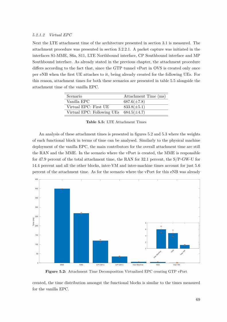
5.2.1.2 Virtual EPC
Next the LTE attachment time of the architecture presented in section 3.1 is measured. Theattachment procedure was presented in section 3.2.2.1. A packet capture was initiated in theinterfaces S1-MME, S6a, S11, LTE Northbound interface, CP Southbound interface and MPSouthbound interface. As already stated in the previous chapter, the attachment procedurediffers according to the fact that, since the GTP tunnel vPort in OVS is created only onceper eNB when the first UE attaches to it, being already created for the following UEs. Forthis reason, attachment times for both these scenarios are presented in table 5.5 alongside theattachment time of the vanilla EPC.
Scenario Attachment Time (ms)Vanilla EPC 687.6(±7.8)Virtual EPC: First UE 833.8(±5.1)Virtual EPC: Following UEs 684.5(±4.7)
Table 5.5: LTE Attachment Times
An analysis of these attachment times is presented in figures 5.2 and 5.3 where the weightsof each functional block in terms of time can be analysed. Similarly to the physical machinedeployment of the vanilla EPC, the main contributors for the overall attachment time are stillthe RAN and the MME. In the scenario where the vPort is created, the MME is responsiblefor 47.9 percent of the total attachment time, the RAN for 32.1 percent, the S/P-GW-U for14.4 percent and all the other blocks, inter-VM and inter-machine times account for just 5.6percent of the attachment time. As for the scenario where the vPort for this eNB was already
MME RAN S/P-GW-U S/P-GW-C Inter-Machine HSS Inter-VM0
50
100
150
200
250
300
350
400
450
Tim
e (
ms)
Inte
r-Mac
hine H
SS
Inte
r-VM
0
2
4
6
8
Figure 5.2: Attachment Time Decomposition Virtualized EPC creating GTP vPort
created, the time distribution amongst the functional blocks is similar to the times measuredfor the vanilla EPC.
69

MME RAN Inter-Machine S/P-GW-C HSS Inter-VM S/P-GW-U0
50
100
150
200
250
300
350
400
450
Tim
e (
ms)
Inte
r-Mac
hine
S/P-G
W-C
HSS
Inte
r-VM
S/P-G
W-U
0
2
4
6
8
Figure 5.3: Attachment Time Decomposition Virtualized EPC without creating GTP vPort
From table 5.5 it can be noted that the process of creating a vPort in the OVS bridgetakes in average 149.3 ms.
5.2.2 Wi-Fi Attachment Time
To measure the attachment time of the Wi-Fi part of the network a similar method to the onepresented in the previous section was used but instead of using the flight mode, the Wi-Fiwas turned on and off in order to perform the 10 tests. The packet captures were initiated ininterfaces STa, STa-DHCP, SWx, SDN-Info, Wi-Fi, Northbound interface, CP Southboundinterface, MP Southbound interface and Wi-Fi CP Southbound interface (see section 3.1).Like before, the time was measured considering a scenario where the GRE tunnel vPort needsto be created and another scenario where the vPort is already created. Refer to section 3.2.3.1for the Wi-Fi attachment procedure. The results obtained for both scenarios are presentedin table 5.6. This attachment time is decomposed into the time taken in each block at the
Scenario Attachment Time (ms)First UE 588.3(±22.9)Following UEs 501.3(±25.4)
Table 5.6: Wi-Fi Attachment Times
time of attachment. Figure 5.4 illustrates this decomposition. In the figure, S/P-GW-U andS/P-GW-C are not represented due to the fact that, because the DHCP server signals theSDN controller to install the flows in the S/P-GW-U’s OVS at the same time that it allocatesan IP address and answers to the UE, the time that the answer needs to reach the UE isgreater than the time needed to install the flows. For that reason, the flow install time is notrelevant for the overall attachment time in a scenario where no vPort is created. On the other
70

hand, when a vPort needs to be created, the difference between the time that the UE receivesthe DHCP answer, the tunnel is created and flows are installed is 87.0(±16.2) ms, whichmeans that, after the UE has completed the L3 attachment procedure, it takes an additional87.0(±16.2) ms for the data plane to be ready to handle the UE’s packets.
RAN AAA DHCP HSS Inter-Machine Inter-VM0
50
100
150
200
250
300
350
400
450
500
550
Tim
e (
ms)
AAA
DHCP
HSS
Inte
r-Mac
hine
Inte
r-VM
0
2
4
6
8
Figure 5.4: Attachment Time Decomposition for Wi-Fi attachment without creating vPort
Lastly, table 5.7 summarizes the results obtained for the attachment times in the proposedarchitecture.
Attachment Time (ms)Creating vPort w/o Creating vPort
LTE 833.8(±5.1) 684.5(±4.7)Wi-Fi 588.3(±22.9) 501.3(±25.4)
Table 5.7: Architecture Attachment Times Summary
5.3 Latency
In this document, the latency of the data plane refers to the Round Trip Time (RTT) of apacket. In this section, the results for the E2E latency are presented accompanied by a studyof the points that contribute for the overall latency. The E2E latency was measured usingthe following method (both for LTE and Wi-Fi): in addition to the architecture presentedin section 3.1, a new VM was deployed and connected to the external network. This VMserves as a sink node for these measurements. Then, a UE (Samsung Galaxy J5 2016 runningAndroid 7.1) was connected to the network. After the connection is established the ping tool,belonging to the Network Tools Package2, was used to generate Internet Control Message
2Ping: https://network-tools.com/
71

Protocol (ICMP) Requests every second and wait for a reply, measuring the time between thetwo. Both the ICMP request and reply have a payload of 48 bytes. A packet capture wasstarted in both endpoints of the data plane interfaces in order to measure the relative timebetween the ICMP request and the reply in each of the data plane functional blocks. 10 pingswere executed and the results are presented in the following sections.
5.3.1 LTE Latency
After connecting the UE to the LTE RAN, the presented procedure was executed for thevanilla EPC and for the virtualized one (refer to section 3.1). The results obtained for boththe implementations are presented next.
5.3.1.1 Vanilla EPC
For the vanilla EPC, the measured E2E latency as seen by the UE was of 21.9(±3.6) ms,being the EPC responsible for just 29.2(±3.6) µs. Combined with the time taken betweenentities, the latency seen by the eNB is of just 598.0(±43.2) µs, being the remaining timespent in eNB procedures and air interface. Figure 5.5 (a) shows the decomposed time seen bythe eNB while on (b) we can see the packet processing time in the EPC in terms of uplinkand downlink.
(a)
eNB to EPC Inside EPC EPC to Sink0
50
100
150
200
250
300
Tim
e (
s)
(b)
Uplink Downlink0
5
10
15
20
25
Tim
e (
s)
Figure 5.5: Latency Decomposition for LTE Vanilla: (a) seen by the eNB; (b) EPC packet processingtime
5.3.1.2 Virtual EPC
In the virtualized architecture, the obtained E2E latency as seen by the UE was of 23.5(±1.9)ms. Table 5.8 shows a comparison between the E2E latency for the vanilla implementationand for the virtualized solution. Figure 5.6 (a) shows the time that the ICMP packets took totraverse the network in each functional block. On figure 5.6 (b) the packet processing time in
72

Vanilla EPC Virtual EPC RelationshipE2E Latency (ms) 21.9(±3.6) 23.5(±1.9) +7%S/P-GW Time (µs) 29.2(±3.6) 61.6(±4.2) +111%
Table 5.8: Comparison between Vanilla and Virtual EPC in terms of E2E latency
the S/P-GW-U for both the uplink and downlink directions is presented. We can verify thatthe virtual EPC is responsible for a small fraction of the measured E2E latency where theeNB procedures and air interface account for most of the latency. As for the packet processingtime in the S/P-GW-U, the time to process the packet in the uplink direction is around 2.8times higher than the processing time for the downlink direction (refer to section 4.5.1 for theS/P-GW-U packet processing pipeline) In terms of S/P-GW packet processing time, there is
(a)
eNB to S/P-GW-U Inside S/P-GW-U S/P-GW-U to Sink0
100
200
300
400
500
600
Tim
e (
s)
(b)
Uplink Downlink0
5
10
15
20
25
30
35
40
45
50
55
Tim
e (
s)
Figure 5.6: Latency Decomposition for LTE: (a) seen by the eNB; (b) S/P-GW-U packet processingtime
a 111 percent increase in the virtual S/P-GW (S/P-GW-U). Despite this increase, it is stillin the order of the µs which is a small increase when compared with the total E2E latencywhich is in the order of the ms.
5.3.2 Wi-Fi Latency
The procedure for the measurement of the E2E latency for the Wi-Fi RAT was similar tothe one used before, connecting this time the UE to the Wi-Fi network. The obtained E2Elatency for Wi-Fi was 14.6(±3.0) ms. This time can be decomposed like it was in the previoussection. The result of the decomposed time is presented in figure 5.7. On figure 5.7 (a) wecan see the time the packets take to travel between entities. On figure 5.7 (b) we can see thepacket processing time of the S/P-GW-U in the uplink and downlink directions (again, referto section 4.5.1 for the S/P-GW-U packet processing pipeline). The obtained times for the
73
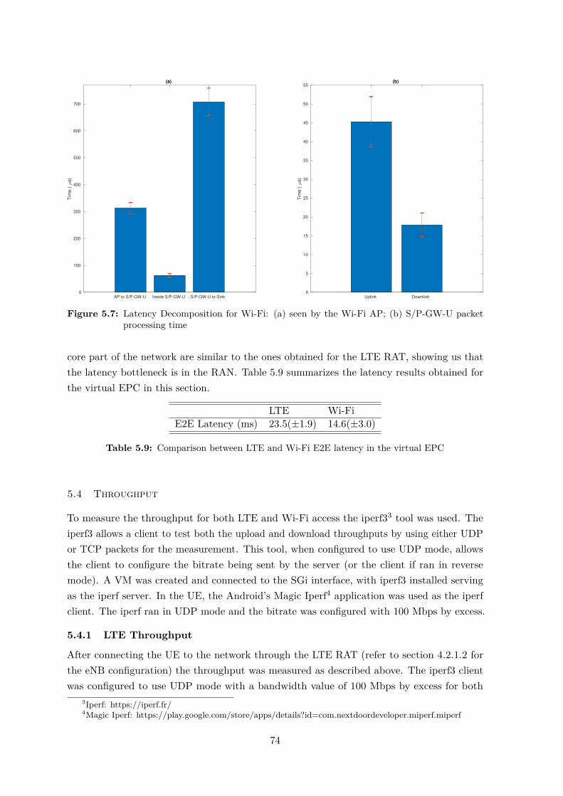
(a)
AP to S/P-GW-U Inside S/P-GW-U S/P-GW-U to Sink0
100
200
300
400
500
600
700
Tim
e (
s)
(b)
Uplink Downlink0
5
10
15
20
25
30
35
40
45
50
55
Tim
e (
s)
Figure 5.7: Latency Decomposition for Wi-Fi: (a) seen by the Wi-Fi AP; (b) S/P-GW-U packetprocessing time
core part of the network are similar to the ones obtained for the LTE RAT, showing us thatthe latency bottleneck is in the RAN. Table 5.9 summarizes the latency results obtained forthe virtual EPC in this section.
LTE Wi-FiE2E Latency (ms) 23.5(±1.9) 14.6(±3.0)
Table 5.9: Comparison between LTE and Wi-Fi E2E latency in the virtual EPC
5.4 Throughput
To measure the throughput for both LTE and Wi-Fi access the iperf33 tool was used. Theiperf3 allows a client to test both the upload and download throughputs by using either UDPor TCP packets for the measurement. This tool, when configured to use UDP mode, allowsthe client to configure the bitrate being sent by the server (or the client if ran in reversemode). A VM was created and connected to the SGi interface, with iperf3 installed servingas the iperf server. In the UE, the Android’s Magic Iperf4 application was used as the iperfclient. The iperf ran in UDP mode and the bitrate was configured with 100 Mbps by excess.
5.4.1 LTE Throughput
After connecting the UE to the network through the LTE RAT (refer to section 4.2.1.2 forthe eNB configuration) the throughput was measured as described above. The iperf3 clientwas configured to use UDP mode with a bandwidth value of 100 Mbps by excess for both
3Iperf: https://iperf.fr/4Magic Iperf: https://play.google.com/store/apps/details?id=com.nextdoordeveloper.miperf.miperf
74

the uplink and downlink measurements. After the 10 tests were performed the measuredthroughput was of 18.4(±0.1) Mbps for the uplink and 71.6(±0.3) Mbps for the downlink.
5.4.2 Wi-Fi Throughput
To test the Wi-Fi (refer to section 4.2.2 for the Wi-Fi AP configuration) throughput ofthe system the same method as for the LTE interface was used with the only parameterdiffering being the configured bandwidth. As already stated in section 4.2.2, the Wi-Fi APwas configured to use the 802.11g 2.4 GHz protocol where the maximum expected throughputis of around 54 Mbps for both the uplink and the downlink so the configured bandwidth forthese iperf tests was of 60 Mbps. The tests in the Wi-Fi interface resulted in a measuredthroughput of 27.1(±0.3) Mbps for the uplink and 23.3(±0.7) Mbps for the downlink. Table5.10 summarises the results obtained in this section.
Throughput (Mbps)Uplink Downlink
LTE 18.4(±0.1) 71.6(±0.3)Wi-Fi 27.1(±0.3) 23.3(±0.7)
Table 5.10: Throughput results for both LTE and Wi-Fi
5.4.3 Throughput Result Validation
After performing the throughput tests as described in the sections above, the throughput ofthe system without the radio part was measured in order to validate the obtained results,which also helps to demonstrate that the bottleneck for the throughput is in fact the radiopart of the network. In order to perform this test, the implementation shown in figure 5.8was used.
veNB1 (VM)
Iperf Client(Container)
OvS
VM
OvS
S/P-GW-U
vRouter
VM
Iperf Server
VM
SDN-CTRL
S/P-GW-C
veNB2 (VM)
Iperf Client(Container)
OvS
S1-U SGi
Figure 5.8: Architecture for S/P-GW-U maximum throughput testing
Two VMs were created, each one representing an eNB which are called Virtual EvolvedNodeBs (veNBs). Inside those VMs one Linux Containers (LXC) container was deployed and
75

connected to an OVS bridge which will simulate an attached client to the veNB in question.The OVS’s function is to create a tunnel endpoint between the veNB and the S/P-GW-U.This OVS was installed and configured like the one in the S/P-GW-U, described in section4.5.1. Since the purpose of this test was to measure the maximum throughput that theS/P-GW-U can cope with, two veNBs were used to make sure that the limitation of themaximum throughput is in the S/P-GW-U. The specifications of the VMs used is presentedin table 5.11 A bash script was developed to install the necessary flows in the corresponding
VM # CPUs RAM (GB) OSIperf Server 1 2.0 Ubuntu Server 16.04 LTSveNB 4 8.0 Ubuntu Server 16.04 LTS
Table 5.11: Resources used by the test architecture’s VMs
veNB switch and to send a REST message to the S/P-GW-C so that it can create the tunnelto the veNB (if not already created) and install the necessary flows in it, simulating theNorthbound Interface messaging. In the clients, the iperf3 tool ran in client mode using UDPand configured with a 500 Mbps bandwidth to try to achieve a throughput of 1 Gbps atthe S/P-GW-U. The throughput of the traffic passing through the S/P-GW-U was measuredusing the iftop tool5. This tool measures the throughput of the desired interfaces and presentsa 40 second average. To allow the iftop tool to have solid data to calculate the averagethroughput in the S/P-GW-U during 40 seconds, the iperf client ran for 50 seconds. Forthe uplink the measurement was performed in the SGi interface and for the downlink it wasmeasured in the S1-U interface. For Wi-Fi, the same method was used with the exceptionthat, refering to figure 5.8, the veNBs are now vAPs and the S1-U interface is now the S2ainterface. Another difference is that the switches in the vAPs are now configured to use GREinstead of GTP for the tunnelling protocol. The results obtained are presented in table 5.12
Throughput (Mbps)Uplink Downlink
veNB (GTP) 531.8(±18.6) 726.1(±15.9)vAP (GRE) 560.8(±16.0) 743.3(±13.2)
Table 5.12: Maximum throughput at the S/P-GW-U considering GTP and GRE tunnelling protocols
In order to validate even further, a throughput measurement was performed directlybetween two VMs using iperf3 (one for the iperf client and another for the server) in UDPmode and setting the bandwidth to 1 Gbps. The same measurements were conducted betweenthe eNB physical machine and a VM and between the Wi-Fi AP physical machine and aVM. The results are presented in table 5.13. These results validate the throughput resultspresented in table 5.10.
5Iftop: http://www.ex-parrot.com/pdw/iftop/
76

Throughput (Mbps)Uplink Downlink
VM to VM 967.1(±6.3) 970.3(±5.0)eNB to VM 945.0(±5.1) 953.5(±4.7)Wi-Fi AP to VM 864.4(±21.4) 900.0(±19.5)
Table 5.13: Validation of the throughput tests conducted in this section
5.5 Use Cases
5.5.1 VoIP Calls
These tests aim to evaluate the resiliency of the implemented architecture in terms of SIPcalls that fail considering various call rates. Only the signalling is considered in the test so noReal Time Protocol (RTP) data is exchanged. The signalling involved in establishing andterminating a SIP call is presented in figure 5.9. To obtain these values, a SIP client and
SIP Client
SIP Server
Invite
180 Ringing
200 OK
ACK
RTP Session
BYE
200 OK
Figure 5.9: SIP call signalling
server were used. The client was installed in a laptop (with 2 CPUs and 8.0 GB of RAM).To connect to the LTE network, a Huawei E398 USB modem was used. The SIP serverwas installed in a VM at the data center. For both the client and the server the SIPp tool6
was used. This tool allows a user to define at the client side the desired call rate and thetime at which the client stops initiating calls and moves on to terminating active calls. Thetimeout was defined to be 30s. The call rate started at 50 Calls Per Second (CPS) and wassuccessively incremented by 50 until it reached 300 CPS. The SIPp client shows the numberof failed calls at the end of a test and the results of this test are presented in figure 5.10.The next test performed in the architecture related to the SIP calls is the evolution of the
6SIPp: http://sipp.sourceforge.net/
77

0 50 100 150 200 250 300
Calls per Second
0
5
10
15
Lost C
alls
Figure 5.10: Failed Calls in function of the Call Rate
throughput generated by the signalling with the increase in the call rate. In order to extractthis information, a packet capture (using tcpdump) was started in the S1-U interface. Then,the capture file is analysed with wireshark7 and, using it’s statistics functions combined with apacket filter to consider only SIP signalling packets, it was possible to obtain the throughputfor each of the tested call rates. The obtained results are presented in figure 5.11.
0 50 100 150 200 250 300
Calls Per Second
0
1
2
3
4
5
6
7
Th
rou
gh
pu
t (M
bp
s)
Figure 5.11: Generated throughput by SIP signalling messages
In order to validate the results, the same test was performed between two VMs directlyconnected. The SIP client was configured to perform 350 CPS. By performing this test itwas verified that no calls were lost.
7Wireshark: https://www.wireshark.org/
78

5.5.2 Mobile Traffic Offloading for Video Streaming
After all the stand alone testing performed on the system, a use case that uses all of thearchitecture was tested. This use case uses the mechanism that enables to seamless offloadtraffic from LTE to Wi-Fi.
5.5.2.1 Scenario Definition
A scenario was defined where a mobile operator strategically deploys multiple APs in a city,allowing the traffic offloading of its clients by dynamically instantiating Wi-Fi slices. Theevaluated scenario starts with a user visualising a live video stream on a mobile. At thebeginning the UE is receiving the video8 via LTE however, in the meantime, the vUE detectscongestion in the mobile cell and it triggers a slice creation. When the UE attaches to thecreated Wi-Fi slice, the video flow is redirected to the UE’s Wi-Fi Interface.
5.5.2.2 Framework Evaluation
To test the framework, a UE (Samsung Galaxy J5 2016 with Android 7.1) was used runningVLC9. The video headend was deployed in a VM with 2 CPUs and 4GB RAM runningUbuntu server 16.04 LTS with VLC installed. VLC was used to transcode the video for theUE standards following the Android video encoding recommendations10. As such, the videowas streamed via RTP-unicast protocol, using H.264 for video encoding at a bitrate of 512kbps. For audio encoding, Moving Picture Experts Group (MPEG) audio was used with abitrate of 128 kbps. Finally, an experiment was recorded and it is available online in ourresearch group’s webpage11. Figure 5.12 shows the throughput of the video over time as wellas key moments. At 2s the vUE requests the SDN controller to instantiate the Wi-Fi slice.Still receiving the live video, the UE attaches (at 22s), in background, to the dynamicallyinstantiated Wi-Fi slice. This triggers the vUE, which in turn redirects (at 22s) the videoflow from the LTE to the Wi-Fi seamlessly, switching from the licensed to the unlicensedspectrum. Figure 5.12 also compares the throughput of the video if it was always receivedvia the congested eNB. Here, despite the throughput being similar in both situations (only2 percent of throughput loss), in the latter the UE receives unsorted packets due to thecongestion, which degrades the user’s QoE (this can be seen in the recording online). In termsof bytes, in the 40s of the assessed video, 50 percent of its total cost (4 Mb) was offloaded toWi-Fi. No lost packets were experienced using this mechanism which was able to redirect theflow to the Wi-Fi slice maintaining the user’s QoE.
As for signalling impact, the dedicated message size is presented in table 5.14 as well asthe payload. The periodic messages represent the signalling impact for one attached UE. Thisimpact will increase with the increase of attached UEs. The handover delay was measuredfrom the moment the UE starts receiving the video via LTE until its redirection to the Wi-Fislice, resulting in an average delay of 36s. Table 5.15 presents the handover delay decomposed
8Video: https://peach.blender.org/9VLC: https://www.videolan.org/
10Android’s video standards: https://developer.android.com/guide/topics/media/media-formats.html11Demo: https://atnog.github.io/5G-VCoM/demos/demo1.html
79

0 10 20 30 40Timeline (s)
0
0.5
1
1.5
Thoughput (M
bps)
t1
t2
t3
LTE Wi-Fi Video in congested eNB
Figure 5.12: Video Throughput over time
Function Protocol Payload (bytes) Total Impact (bytes)Create Slice UDP 14 60Route Update OF 112 178UE Flow info request: periodic OF 72 138UE Flow info response: periodic OF 128 194
Table 5.14: Impact of dedicated signalling messages
in its four stages. ∆t1 refers to the time it takes for the video flow to be detected. Since the
∆ t1 ∆ t2 ∆ t3 ∆ t4delay (s) 5.44(±0.78) 8.52(±0.01) 21.35(±8.91) 0.10(±0.02)
Table 5.15: Decomposed Offloading Delay
period of data updates in the vUE was pre-configured with 5s, the mechanism had a delay of5.44(±0.78). ∆t2 refers to the slice instantiation delay. ∆t3 is the time interval between theslice creation and the UE detection and attachment to the dynamically instantiated Wi-Fislice. However, such delay is independent of this mechanism since it is related to the Android’sconnectivity manager. In this case, the framework waits for the connectivity manager todetect the created slice for further attachment request. From the 21.35s delay, only 0.6s wererelated to the attachment procedure. Finally, ∆t4 is the delay between the UE’s successfulattachment and the flow redirection.
5.6 Summary
This chapter presented the results of the architecture’s evaluation. The messages of the newlyimplemented interfaces were analysed as well as the impact of the signalling in the control
80

plane interfaces in terms of generated throughput and overhead. Also, the attachment times,E2E latency and maximum throughput supported by the system were measured, with resultsshowing that the bottleneck of the system resides in the LTE and Wi-Fi air interfaces. Finally,two use cases for the architecture were evaluated: one evaluated the capacity that the networkhas to carry SIP calls while the other evaluated the performance of the traffic offloadingmechanism.
The next chapter presents the thesis’ conclusions, main contributions and future work.
81


CHAPTER 6Final Remarks
6.1 Conclusions
The execution of this thesis resulted in an architecture implementation of a mobile corenetwork for 4G deployed in a cloud environment (network functions deployed as VNFs),using SDN and supporting Wi-Fi access. The architecture uses an authentication methodcommon for LTE and Wi-Fi access and both these methods are transparent to the user. Thearchitecture also provides a mechanism for traffic offloading between LTE and Wi-Fi.
From the execution of this thesis and from the results presented in chapter 5, we canconclude that the proposed architecture is more flexible than the standard approach for EPCdeployment as the introduction of SDN allows, as it was shown, for a reconfiguration of thenetwork behaviour during run-time. This flexibility becomes evident in the video streamingtraffic offloading use case where it was possible to dynamically redirect traffic flows from oneaccess technology to the other without losing QoE, freeing resources in the mobile cell andthus optimizing the overall available resources. In terms of attachment time, compared witha vanilla EPC, the proposed architecture had, when the tunnel port was already created,attachment times similar to the ones measured in the bare metal EPC, despite being deployedin a virtualization environment. Taking into consideration the variation of the confidenceinterval associated with the results presented, the proposed architecture might even presentattachment times lower than in the bare metal EPC. So, in this case, the virtualizationimpact in the attachment times for LTE access was counteracted by the modifications madeto the base EPC. In terms of data plane latency, the proposed architecture increased the E2Elatency in around 7 percent. Despite this increase, the majority of the time that contributesto this latency is spent in the RAN. One conclusion drawn from the tests performed onthe implemented architecture was that the bottleneck of the system resides in the RAN.Also, by deploying the network functions inside VMs in a cloud environment, the proposedarchitecture decouples the software from the hardware enabling both to be updated andscaled independently. This feature became evident when it was necessary to migrate theimplemented architecture to a new Openstack cloud environment that used different hardware
83

(the first deployment used AMD based CPUs while the latter, that was used to perform thetests presented in this thesis, used Intel based CPUs). Despite the difference in hardware, nomodification was needed in the software of the implemented architecture.
The architecture implemented and presented in this thesis is an evolution of the standardEPC and it uses concepts that are envisioned for 5G deployments such as SDN, NFV andvirtualization. It serves as a starting point test bed for more advanced and standards compliant5G deployments and for the deployment of new network services.
6.2 Main Contributions
The execution of this thesis resulted in a physical test bed for future mobile network de-ployments and presented an evaluation of the same. This thesis complements the relatedwork presented in chapter 2 where the majority of the work related to virtualization andintroduction of SDN in mobile networks only presented the architectures or simulation results.
Regarding to outcomes of this dissertation, the main outcome was the traffic offloadingmechanism that was jointly developed with an on-going PhD thesis. Another outcome was thenewly implemented interface called SDN-Info, that provides information to the DHCP serverthat allows it to associate the MAC address of the UE to its IMSI. Also, the SWx interfacewas implemented and this implementation resulted in a freeDIAMETER patch containingthe SWx interface necessary AVPs and message definitions. The integration of SDN in theS/P-GW resulted in a REST module that enables the S/P-GW to communicate with theSDN controller. Overall, the main outcome of this was the implemented SDN mechanismsthat provide a higher level of programmability to the network.
The architecture implemented and evaluated in this thesis is currently being used in ourresearch group as the basis for advanced services that are framed with 5G deployments. Theexecution of this thesis contributed to a paper, entitled "Using SDN and Slicing for DataOffloading over Heterogeneous Networks Supporting non-3GPP Access", accepted to the IEEEInternational Symposium on Personal, Indoor and Mobile Radio Communications (PIMRC)2018 with the authors Flávio Meneses, Rui Silva, David Santos, Daniel Corujo and Rui L.Aguiar. In this paper, the architecture presented in this thesis was used as the basis for theevaluated traffic offloading mechanism.
This thesis also resulted in a journal submission entitled "An Integration of Slicing, NFVand SDN for Mobility Management in Corporate Environments" with the authors FlávioMeneses, Rui Silva, David Santos, Daniel Corujo and Rui L. Aguiar, submitted to theTransactions on Emerging Telecommunications Technologies journal. This submission usesthe architecture from this thesis as the default slice, with 4G and Wi-Fi access, and it providesa framework to redirect the desired traffic to a corporate slice.
This thesis was presented at the 25th Seminar of Rede Temática de Comunicações Móveis(RTCM) 2018. Contributions were also made to the "Mobilizador 5G" project throughparticipation in audio conference meetings.
84

6.3 Future Work
With the 5G standardization process in progress there are several action points that can beaddressed in order to evolve the architecture proposed in this thesis. The future work to evolvethe architecture involves the deployment of multiple eNBs and perform network initiatedhandovers, developing a mechanism to seamlessly transition a UE from a congested cell toanother with a higher amount of available resources. Also, the presented architecture couldbe deployed on demand and managed by a NFV MANO system where it becomes possibleto deploy the entire architecture as a network service using a VNFD and network servicedescriptors. Also, using the NFV MANO, the architecture would include scaling and healingcapabilities. The SDN controller application developed has room for improvement. One ofthose improvements is to develop a mechanism for load balancing. The load balancing in thiscontext would mean that selective flows would be redirected to a parallel gateway connectedto the same SDN controller.
This thesis presented a mechanism for Wi-Fi slice creation. In order to have an E2Eslice in LTE, LTE RAN level slicing is also needed. As future work, a mechanism could beimplemented to support E2E network slicing in LTE and future 5G architectures.
In order to lower the latency felt by users when using a particular service, a Multi-AccessEdge Computing (MEC) framework could be incorporated with this architecture, which allowsfor certain services to be deployed closer to the end user. The future work related to the MECconcept includes the development of edge assisted handovers, performing faster handovers. Italso includes the deployment of distributed S/P-GW (as referenced by the ETSI in the "MECDeployments in 4G and Evolution Towards 5G" white paper) where the traffic originatingfrom the eNB can be decapsulated at the edge of the network and processed there, reducingthe bandwidth in the link with the core network and reducing the latency felt by the end user.
85


References
[1] Cisco, «Cisco Visual Networking Index : Global Mobile Data Traffic Forecast , 2016 – 2021», CISCO,White Paper, Feb. 2017, pp. 1–7, 2017, issn: 1553-877X. doi: 10.1109/SURV.2008.080403. arXiv:1454457600809267. [Online]. Available: http://www.cisco.com/en/US/solutions/collateral/ns341/ns525/ns537/ns705/ns827/white%7B%5C_%7Dpaper%7B%5C_%7Dc11-520862.html.
[2] NGMN Alliance, «NGMN 5G White Paper», Ngmn, pp. 1–125, 2015, issn: 0027-9684.
[3] 3GPP, «Non-Access-Stratum (NAS) protocol for Evolved Packet System (EPS); Stage 3», 3rd GenerationPartnership Project (3GPP), TS 24.301, 2008. [Online]. Available: http://www.3gpp.org/ftp/Specs/html-info/24301.htm.
[4] 3GPP, «Evolved Universal Terrestrial Radio Access (E-UTRA) and Evolved Universal Terrestrial RadioAccess (E-UTRAN); Overall description; Stage 2», 3rd Generation Partnership Project (3GPP), TS36.300, 2008. [Online]. Available: http://www.3gpp.org/ftp/Specs/html-info/36300.htm.
[5] 3GPP, «Network architecture», 3rd Generation Partnership Project (3GPP), TS 23.002, 2008. [Online].Available: http://www.3gpp.org/ftp/Specs/html-info/23002.htm.
[6] 3GPP, «Policy and charging control architecture», 3rd Generation Partnership Project (3GPP), TS23.203, 2008. [Online]. Available: http://www.3gpp.org/ftp/Specs/html-info/23203.htm.
[7] 3GPP, «General Packet Radio Service (GPRS) enhancements for Evolved Universal Terrestrial RadioAccess Network (E-UTRAN) access», 3rd Generation Partnership Project (3GPP), TS 23.401, 2008.[Online]. Available: http://www.3gpp.org/ftp/Specs/html-info/23401.htm.
[8] S. Ahmadi, LTE-Advanced: A Practical Systems Approach to Understanding 3GPP LTE Releases 10 and11 Radio Access Technologies. 2013, pp. 1–1116, isbn: 9780124051621. doi: 10.1016/C2012-0-02224-7.
[9] 3GPP, «Evolved Universal Terrestrial Radio Access (E-UTRA) ; S1 Application Protocol (S1AP)», 3rdGeneration Partnership Project (3GPP), TS 36.413, 2008. [Online]. Available: http://www.3gpp.org/ftp/Specs/html-info/36413.htm.
[10] V. Fajardo, J. Arkko, J. Loughney, and G. Zorn, Diameter Base Protocol, RFC6733, Oct. 2012. [Online].Available: http://tools.ietf.org/rfc/rfc6733.txt.
[11] 3GPP, «MME Related Interfaces Based on Diameter Protocol», 3rd Generation Partnership Project(3GPP), TS 29.272, 2008. [Online]. Available: http://www.3gpp.org/ftp/Specs/html-info/29272.htm.
[12] «IEEE Standard for Information technology–Telecommunications and information exchange betweensystems Local and metropolitan area networks–Specific requirements - Part 11: Wireless LAN MediumAccess Control (MAC) and Physical Layer (PHY) Specifications», IEEE Std 802.11-2016 (Revision ofIEEE Std 802.11-2012), pp. 1–3534, Dec. 2016. doi: 10.1109/IEEESTD.2016.7786995.
[13] F. Rebecchi, M. Dias de Amorim, V. Conan, A. Passarella, R. Bruno, and M. Conti, «Data OffloadingTechniques in Cellular Networks: A Survey», IEEE Communications Surveys & Tutorials, vol. 17, no. 2,pp. 580–603, 2015, issn: 1553-877X. doi: 10.1109/COMST.2014.2369742.
[14] K. Samdanis, T. Taleb, and S. Schmid, «Traffic offload enhancements for eUTRAN», IEEE Communi-cations Surveys and Tutorials, vol. 14, no. 3, pp. 884–896, 2012, issn: 1553877X. doi: 10.1109/SURV.2011.072711.00168.
[15] C. B. Sankaran, «Data offloading techniques in 3GPP Rel-10 networks: A tutorial», IEEE Communica-tions Magazine, vol. 50, no. 6, pp. 46–53, 2012, issn: 01636804. doi: 10.1109/MCOM.2012.6211485.
87

[16] 3GPP, «Architecture enhancements for non-3GPP accesses», 3rd Generation Partnership Project (3GPP),TS 23.402, 2008. [Online]. Available: http://www.3gpp.org/ftp/Specs/html-info/23402.htm.
[17] 3GPP, «Evolved Packet System (EPS); 3GPP EPS AAA interfaces», 3rd Generation Partnership Project(3GPP), TS 29.273, 2008. [Online]. Available: http://www.3gpp.org/ftp/Specs/html-info/29273.htm.
[18] 3GPP, «Access Network Discovery and Selection Function (ANDSF) Management Object (MO)», 3rdGeneration Partnership Project (3GPP), TS 24.312, 2008. [Online]. Available: http://www.3gpp.org/ftp/Specs/html-info/24312.htm.
[19] D. Laselva, D. Lopez-Perez, M. Rinne, and T. Henttonen, «3GPP LTE-WLAN Aggregation Technologies:Functionalities and Performance Comparison», IEEE Communications Magazine, vol. 56, no. 3, pp. 195–203, Mar. 2018, issn: 0163-6804. doi: 10.1109/MCOM.2018.1700449.
[20] D. R. Purohith, A. Hegde, and K. M. Sivalingam, «Network architecture supporting seamless flowmobility between LTE and WiFi networks», in Proceedings of the WoWMoM 2015: A World of WirelessMobile and Multimedia Networks, 2015, isbn: 9781479984619. doi: 10.1109/WoWMoM.2015.7158124.
[21] S. Gundavelli, K. Leung, V. Devarapalli, K. Chowdhury, and B. Patil, Proxy Mobile IPv6, RFC5213,Aug. 2008. [Online]. Available: http://tools.ietf.org/rfc/rfc5213.txt.
[22] D. Johnson, C. Perkins, and J. Arkko, Mobility Support in IPv6, RFC3775, Jun. 2004. [Online]. Available:http://tools.ietf.org/rfc/rfc3775.txt.
[23] A. S. D. Alfoudi, G. M. Lee, and M. Dighriri, «Seamless LTE-WiFi Architecture for Offloading theOverloaded LTE with Efficient UE Authentication», in Proceedings - 2016 9th International Conferenceon Developments in eSystems Engineering, DeSE 2016, 2017, pp. 118–122, isbn: 9781509054879. doi:10.1109/DeSE.2016.53.
[24] 3GPP, «NR and NG-RAN Overall Description», 3rd Generation Partnership Project (3GPP), TS 38.300,2017. [Online]. Available: http://www.3gpp.org/ftp/Specs/html-info/38300.htm.
[25] 3GPP, «System Architecture for the 5G System», 3rd Generation Partnership Project (3GPP), TS23.501, 2017. [Online]. Available: http://www.3gpp.org/ftp/Specs/html-info/23501.htm.
[26] S. Carl-Mitchell and J. Quarterman, Using ARP to implement transparent subnet gateways, RFC1027,Oct. 1987. [Online]. Available: http://tools.ietf.org/rfc/rfc1027.txt.
[27] P. Eronen, IKEv2 Mobility and Multihoming Protocol (MOBIKE), RFC4555, Jun. 2006. [Online].Available: http://tools.ietf.org/rfc/rfc4555.txt.
[28] ETSI, «Network Functions Virtualisation (NFV); Architectural Framework», ETSI GS NFV 002 v1.2.1,vol. 1, pp. 1–21, 2014. doi: DGS/NFV-0011.
[29] ETSI, «Network Functions Virtualization (NFV) Release 3; Management and Orchestration; Report onmanagement of NFV-MANO and automated deployment of EM and other OSS functions», EuropeanTelecommunications Standards Institute (ETSI), GR NFV-IFA 021, 2018. [Online]. Available: www.etsi.org/deliver/etsi_gr/NFV-IFA/001_099/021/03.01.01_60/gr_NFV-IFA021v030101p.pdf.
[30] ETSI, «Network Functions Virtualization (NFV); Virtual Network Functions Architecture», EuropeanTelecommunications Standards Institute (ETSI), GS NFV-SWA 001, 2014. [Online]. Available: http://www.etsi.org/deliver/etsi_gs/NFV-SWA/001_099/001/01.01.01_60/gs_nfv-swa001v010101p.pdf.
[31] E. Haleplidis, K. Pentikousis, S. Denazis, J. H. Salim, D. Meyer, and O. Koufopavlou, Software-DefinedNetworking (SDN): Layers and Architecture Terminology, RFC7426, Jan. 2015. [Online]. Available:http://tools.ietf.org/rfc/rfc7426.txt.
[32] J. Halpern and J. H. Salim, Forwarding and Control Element Separation (ForCES) Forwarding ElementModel, RFC5812, Mar. 2010. [Online]. Available: http://tools.ietf.org/rfc/rfc5812.txt.
[33] M. Bjorklund, YANG - A Data Modeling Language for the Network Configuration Protocol (NETCONF),RFC6020, Oct. 2010. [Online]. Available: http://tools.ietf.org/rfc/rfc6020.txt.
[34] ONF, «OpenFlow Switch Specification», Open Networking Foundation (ONF), TS ONF TS-023,2015. [Online]. Available: https : / / 3vf60mmveq1g8vzn48q2o71a - wpengine . netdna - ssl . com / wp -content/uploads/2014/10/openflow-switch-v1.3.5.pdf.
88

[35] R. Thurlow, RPC: Remote Procedure Call Protocol Specification Version 2, RFC5531, May 2009. [Online].Available: http://tools.ietf.org/rfc/rfc5531.txt.
[36] A. Jain, N. S. Sadagopan, S. K. Lohani, and M. Vutukuru, «A comparison of SDN and NFV forre-designing the LTE Packet Core», in 2016 IEEE Conference on Network Function Virtualization andSoftware Defined Networks, NFV-SDN 2016, 2017, pp. 74–80, isbn: 9781509009336. doi: 10.1109/NFV-SDN.2016.7919479.
[37] A. Basta, W. Kellerer, M. Hoffmann, K. Hoffmann, and E. D. Schmidt, «A virtual SDN-enabled LTEEPC architecture: A case study for S-/P-gateways functions», in SDN4FNS 2013 - 2013 Workshopon Software Defined Networks for Future Networks and Services, 2013, isbn: 9781479927814. doi:10.1109/SDN4FNS.2013.6702532.
[38] S. B. H. Said, M. R. Sama, K. Guillouard, L. Suciu, G. Simon, X. Lagrange, and J. M. Bonnin, «Newcontrol plane in 3GPP LTE/EPC architecture for on-demand connectivity service», in Proceedings ofthe 2013 IEEE 2nd International Conference on Cloud Networking, CloudNet 2013, 2013, pp. 205–209,isbn: 9781479905669. doi: 10.1109/CloudNet.2013.6710579.
[39] X. An, W. Kiess, J. Varga, J. Prade, H. J. Morper, and K. Hoffmann, «SDN-based vs. software-onlyEPC gateways: A cost analysis», in IEEE NETSOFT 2016 - 2016 IEEE NetSoft Conference andWorkshops: Software-Defined Infrastructure for Networks, Clouds, IoT and Services, 2016, pp. 146–150,isbn: 9781467394864. doi: 10.1109/NETSOFT.2016.7502461.
[40] A. Tawbeh, H. Safa, and A. R. Dhaini, «A hybrid SDN/NFV architecture for future LTE networks»,in IEEE International Conference on Communications, 2017, isbn: 9781467389990. doi: 10.1109/ICC.2017.7997391.
[41] J. Kempf, B. Johansson, S. Pettersson, H. Lüning, and T. Nilsson, «Moving the mobile evolved packetcore to the cloud», in International Conference on Wireless and Mobile Computing, Networking andCommunications, 2012, pp. 784–791, isbn: 9781467314305. doi: 10.1109/WiMOB.2012.6379165.
[42] R. Droms, Dynamic Host Configuration Protocol, RFC2131, Mar. 1997. [Online]. Available: http://tools.ietf.org/rfc/rfc2131.txt.
89


Appendix-A: oai-spgw source codemodifications
UE Information Structure
typedef struct {Imsi_t imsi;struct in_addr enb_ip;struct in_addr ue_ip;uint32_t enb_s1u_teid;uint32_t spgw_s1u_teid;
} ue_info;
sdn_rest module
int create_gtpv1u_tunnel(void *args){
/* ... */// Convert args to ue_info structurememcpy(ue, args, sizeof(ue_info));
/* ... */
// Build URI stringsprintf(uri, "http://%s:%u/spgw/ue/lte/add", sdn_ctrl_ip, sdn_ctrl_port);
// Build info stringsprintf(info, "{\"imsi\": %s, \"ue_ip\": \"%s\", \"enb_ip\": \"%s\", \"enb_s1u_teid\": %u,
\"sgw_s1u_teid\": %u}", imsi, ue_ip, enb_ip, ue->enb_s1u_teid, ue->sgw_s1u_teid);
// Send data to SDN Controller and return exit codereturn curl_post_data(uri, info);
}
int delete_gtpv1u_tunnel(void *args){
/* ... */// Convert args to imsimemcpy(imsi, args, sizeof(Imsi_t));
/* ... */
91

// Build URI stringsprintf(uri, "http://%s:%u/spgw/ue/lte/delete", sdn_ctrl_ip, sdn_ctrl_port);
// Build info stringsprintf(info, "{\"imsi\": %s}", imsi);
// Send data to SDN Controller and return exit codereturn curl_post_data(uri, info);
}
Modifications to the sgw_handlers.c file
intsgw_handle_sgi_endpoint_updated (
const itti_sgi_update_end_point_response_t * const resp_pP){
/* ... */pthread_t create_gtp_tunnel;ue_info *ue_information;
/* ... */
// Line to be replaced://rv = gtp_mod_kernel_tunnel_add(ue, enb, eps_bearer_entry_p->s_gw_teid_S1u_S12_S4_up,// eps_bearer_entry_p->enb_teid_S1u);
// Create Tunnel in OVS via REST API// Fill in ue_information structure/* ... */// Create Threadret = pthread_create(&create_gtp_tunnel, NULL, create_gtpv1u_tunnel, ue_information);if(ret){
//print error message}// Wait for thread to be completedpthread_join(create_gtp_tunnel, NULL);/* ... */
}
intsgw_handle_sgi_endpoint_deleted (
const itti_sgi_delete_end_point_request_t * const resp_pP){
/* ... */pthread_t delete_gtp_tunnel;
/* ... */
// Line to be replaced:
92

//rv = gtp_mod_kernel_tunnel_del(eps_bearer_entry_p->s_gw_teid_S1u_S12_S4_up,// eps_bearer_entry_p->enb_teid_S1u);
// Delete Tunnel in OVS via REST API
ret = pthread_create(&delete_gtp_tunnel, NULL, delete_gtpv1u_tunnel, (void *)imsi);if(ret){
//print error message}// Wait for thread to be completepthread_join(delete_gtp_tunnel, NULL);/* ... */
}
93


Appendix-B: SDN ControllerApplication
vSwitch Initial Connection Handler
def switch_features_handler(self, ev):# ..dpid = datapath.id# ...
if dpid == SPGW_DPID:# Install SPGW default flows# ...# Send Command to retrieve switch port list
elif dpid == WIFI_AP_DPID:# Install WIFI_AP default flows# ...
elif dpid == DHCP_DPID:# Install DHCP default flows# ...
else:# Unrecognised datapath# ...
Port Description Reply Handler
def port_desc_stats_reply_handler(self, ev):for p in ev.msg.body:
ports[p.name] = p.port_no# ...
Port Status Handler
def port_status_handler(self, ev):msg = ev.msg# ...
95

if msg.reason == ofp.OFPPR_ADD:# ...ports[port.name] = port.port_no
if msg.reason == ofp.OFPPR_DELETE:# ...del ports[port.name]
mobileNode Class
class MobileNode():def __init__(self, imsi):
self.imsi = imsi # dictionary key## Cellular Infoself.lte_ip = Noneself.lte_remote_teid = Noneself.lte_local_teid = Noneself.lte_tun_ipv4_dst = Noneself.gtp_port = None
## WIFI Infoself.wifi_ip = Noneself.wifi_remote_teid = Noneself.wifi_tun_ipv4_dst = Noneself.gre_port = None
def register_lte(self, spgw_dp, ip, remote_teid, local_teid, tun_ipv4_dst):self.lte_ip = ipself.lte_remote_teid = remote_teidself.lte_local_teid = local_teidself.lte_tun_ipv4_dst = tun_ipv4_dstgtp_port_name = self.lte_tun_ipv4_dst
if gtp_port_name in ports:self.gtp_port = ports[gtp_port_name]
else:# Create GTP Tunnel portcreate_gtp_port(self.lte_tun_ipv4_dst)# Wait for the switch to signal that a new port was createdwhile gtp_port_name not in ports:
pass
self.gtp_port = ports[gtp_port_name]# ...# Install Uplink and Downlink flows
def unregister_lte(self, spgw_dp):# ...# Delete Uplink and Downlink flows# ...self.lte_ip = None
96

def register_wifi(self, spgw_dp, ap_dp, wifi_ip, tun_ipv4_dst):self.wifi_ip = wifi_ipself.wifi_remote_teid = self.get_free_teid()self.wifi_tun_ipv4_dst = tun_ipv4_dstgre_port_name = self.wifi_tun_ipv4_dstif gre_port_name in ports:
self.gre_port = ports[gre_port_name]else:
# Create GRE Tunnel Port in S/P-GW-Ucreate_wifi_port(self.wifi_tun_ipv4_dst)# Wait for the switch to signal that a new port was createdwhile gre_port_name not in ports:
pass
self.gre_port = ports[gre_port_name]# ...
# Install S/P-GW-U Uplink and Downlink Flows# ...# Install Wi-Fi AP Uplink and Downlink Flows
def unregister_wifi(self, spgw_dp, ap_dp):# ...# Delete S/P-GW-U Uplink and Downlink Flows# ...# Delete Wi-Fi AP Uplink and Downlink Flows# ...self.wifi_ip = None
Handlers for REST messages
/spgw/ue/lte/add and deletedef add_lte_if(self, req, body, *args, **kwargs):
# ...imsi = body['imsi']
if imsi in mobile_nodes: # If the UE is already connected via Wi-Fimn = mobile_nodes[imsi]mn.register_lte(spgw_dp, body['ue_ip'], body['enb_s1u_teid'],
body['sgw_s1u_teid'], body['enb_ip'])
else: # No UE is connected with this IMSImn = MobileNode(imsi) # Create the structuremn.register_lte(spgw_dp, body['ue_ip'], body['enb_s1u_teid'],
body['sgw_s1u_teid'], body['enb_ip'])mobile_nodes[imsi] = mn
def delete_lte_if(self, req, body, *args, **kwargs):# ...imsi = body['imsi']
97

if imsi in mobile_nodes: # If the UE is connectedmn = mobile_nodes[imsi]mn.unregister_lte(spgw_dp)if mn.wifi_ip == None: # If the UE is not connected to Wi-Fi
del mobile_nodes[imsi]
else: # UE is not registered# Print error message
/spgw/ue/wifi/add and deletedef add_wifi_if(self, req, body, *args, **kwargs):
# ...imsi = body['imsi']
if imsi in mobile_nodes: # If the UE is already connected via LTEmn = mobile_nodes[imsi]mn.register_wifi(spgw_dp, ap_dp, body['ue_ip'], body['ap_ip'])
else: # No UE is connected with this IMSImn = MobileNode(imsi) # Create the structuremn.register_wifi(spgw_dp, ap_dp, body['ue_ip'], body['ap_ip'])mobile_nodes[imsi] = mn
def delete_wifi_if(self, req, body, *args, **kwargs):# ...imsi = body['imsi']if imsi in mobile_nodes: # If the UE is connected
mn = mobile_nodes[imsi]mn.unregister_wifi(spgw_dp, ap_dp)if mn.lte_ip == None: # If the UE is not connected to LTE
del mobile_nodes[imsi]
else: # UE is not registered# Print error message
98

Appendix-C: freeRADIUS serversource code modifications and
diameter-agent
Modifications to the freeRADIUS serversrc/modules/rlm_eap/lib/sim/vector.c file
static int vector_umts_from_ki(eap_session_t *eap_session, VALUE_PAIR *vps, fr_sim_keys_t *keys){
/*...*/// Extract UE MAC Address and Wi-Fi AP IP Address from eap_session variable/*...*/// Open UDP socket// Set DHCP Server IP and Port// Send UDP Message to DHCP Server containing the user's IMSI, the MAC Address and
// the Wi-Fi AP IP Address// Close UDP Socket
// Open UDP socket// Set diameter-agent IP and Port// Send UDP Message to diameter-agent with the user's IMSI// Wait for a response// Close socket// Extract RAND, AUTN, XRES, CK and IK from received message and set the values
//in the keys variable/*...*/return 0;
}
diameter-agent
/*...*/typedef struct{
struct dict_object *dataobj_swx_vendor; /* swx vendor object */struct dict_object *dataobj_swx_app; /* swx application object *//* Commands */struct dict_object *dataobj_swx_auth_req_cmd; /* SWx-MultimediaAuthentication-Request */
99

struct dict_object *dataobj_swx_auth_ans_cmd; /* SWx-MultimediaAuthentication-Answer *//* AVPs */// Define the objects for the AVPs// struct dict_object *dataobj_swx_*;/*...*/
}swx_cnf_t;
// EAP-AKA Vectortypedef struct{
uint8_t autn[SIM_VECTOR_UMTS_AUTN_SIZE];uint8_t ck[SIM_VECTOR_UMTS_CK_SIZE];uint8_t ik[SIM_VECTOR_UMTS_IK_SIZE];uint8_t rand[SIM_VECTOR_UMTS_RAND_SIZE];uint8_t xres[SIM_VECTOR_UMTS_RES_MAX_SIZE];uint32_t xres_len;
} umts_vector_t;
// The main function: Opens the socket, initializes the SWx interface and waits for messages//to arrive to the UDP socket
int main(){
udp_socket_open();swx_init();while(1);return 0;
}
int swx_init(){
/*...*/// Initialize freediameter coreret = fd_core_initialize ();/*...*/// Parse Configurationsret = fd_core_parseconf (config_file);/*...*/// Start freediameter Coreret = fd_core_start ();/*..*/// Wait for the start completionret = fd_core_waitstartcomplete ();/*...*/// Initialize SWx dictionary Objects (Application Specific)ret = swx_fd_init_dict_objs ();/*...*/
memset (&when, 0, sizeof (when));when.command = swx_cnf.dataobj_swx_auth_ans_cmd;when.app = swx_cnf.dataobj_swx_app;
100

// Register the callbacks for SWx ApplicationCHECK_FCT (fd_disp_register (swx_auth_ans, DISP_HOW_CC, &when, NULL, &handle));/*...*/return 0;
}
int swx_fd_init_dict_objs (void){
vendor_id_t vendor_3gpp = VENDOR_3GPP;application_id_t app_swx = APP_SWX;/*...*/// Pre-load vendor object/*...*/// Pre-load application object/*...*/// Pre-load command objects/*...*/// Pre-load AVPs objects/*...*///Add support for the SWx applicationCHECK_FCT (fd_disp_app_support (swx_cnf.dataobj_swx_app, swx_cnf.dataobj_swx_vendor, 1, 0));
return 0;}
// Handler called when an UDP message is receivedvoid SIGIOHandler(int signalType){
/*...*/// Get received message from buffer (user's IMSI)/*...*/swx_generate_auth_info_req (buffer);/*...*/
}
int swx_generate_auth_info_req (char *identity){
/*...*/// Create the new Multimedia-Auth Request message/*...*/// Create new Session/*...*/// Add required AVPs to message/*...*/// Send the messageCHECK_FCT (fd_msg_send (&msg, NULL, NULL));
return 0;}
101

// The handler for the Multimedia-Auth Answer messageintswx_auth_ans (
struct msg **msg,struct avp *paramavp,struct session *sess,void *opaque,enum disp_action *act)
{/*...*/// Retrieve the result code from the messageif(result_code != ER_DIAMETER_SUCCESS)
// An error occurred, print error messageelse
// Retrieve Authentication Vector from messageCHECK_FCT (swx_parse_umts_vector (avp, vector));
// Build UDP Message to send to RADIUS Server/*...*/// Send UDP Message to RADIUS Server/*...*/
return 0;}
102

Appendix-D: SDN interface in theDHCP server
Wi-Fi SDN Interface
# ...
ids = {} # Dictionary for the MAC <-> IMSI Associationtunnel_ip = {} # Dictionary for the IMSI <-> Wi-Fi AP IP Associationdhcp_leases = {} # Dictionary to store the DHCP Leases
# ...
def ue_register(added, new_leases):for i in range(len(added)):
key = added.pop() # Retrieve the MAC Address of the added UEtry:
# Build data string with data from ids and tunnel_ip dicts# ...# Build URI string# ...# Create and start a thread to send the REST Command to the SDN
# Controllert = threading.Thread(target = curl_post_data, args=(url,data))t.start()
except:# An error occurred
def ue_unregister(removed):for i in range(len(removed)):
key = removed.pop() # Retrieve the MAC Address of the removed UEtry:
# Build data string with data from ids# ...# Build URI string# ...# Create and start a thread to send the REST Command to the SDN
# Controllert = threading.Thread(target = curl_post_data, args=(url,data))t.start()
103

except:# An error occurred
def curl_post_data(url, data):# Use pycurl to send data to SDN Controller
class UDPHandler(SocketServer.BaseRequestHandler):def handle(self):
# Retrieve received data (IMSI, Wi-Fi AP IP and MAC Address)# ...# Associate the IMSI to the MAC addressids[mac] = imsi# Associate the Wi-Fi AP IP to the IMSItunnel_ip[imsi] = ap_ip
if __name__ == "__main__":# Start UDP Server# ...try:
# ...while True:
# Read DHCP Leases File# ...
# Compare the leases with the leases in the previous reading# It compares new_leases with dhcp_leasesadded, removed = dict_compare(new_leases)if len(added) > 0: # If new leases where added
ue_register(added, new_leases)
if len(removed) > 0: # If leases where removedue_unregister(removed)
# Save Current leasesdhcp_leases = new_leases
104