RTML Emittance Measurement Station
16
1 RTML Emittance Measurement Station Yuri Kubyshin (1), Robert Apsimon (2), Hector García (1,2) (1) Technical University of Catalonia (UPC) (2) CERN 13
description
RTML Emittance Measurement Station. Yuri Kubyshin (1), Robert Apsimon (2), Hector García (1,2) (1) Technical University of Catalonia (UPC) (2) CERN. CLIC Workshop 2013 January 29, 2013. Talk outline: - PowerPoint PPT Presentation
Transcript of RTML Emittance Measurement Station

1
RTML Emittance Measurement Station
Yuri Kubyshin (1), Robert Apsimon (2), Hector García (1,2)
(1) Technical University of Catalonia (UPC)(2) CERN
CLIC Workshop 2013 January 29, 2013
CLIC Workshop 2013 229/01/2013
Talk outline:
1. Emittance measurement section (EMS) at the RTML line2. Emittance measurement scheme3. Optics of the EMS and measurement simulations4. Proposal of the laser wire (LW) monitor5. Concluding remarks
•Yu. Kubyshin, H. Garcia, E. Marin, D. Schulte, F. Stulle, PAC-2011•H. Garcia, Yu. Kubyshin, G. Blair, T. Aumeyr, D. Schulte, F. Stulle, IPAC-2011•R. Apsimon, CLIC seminar 14/11/2012
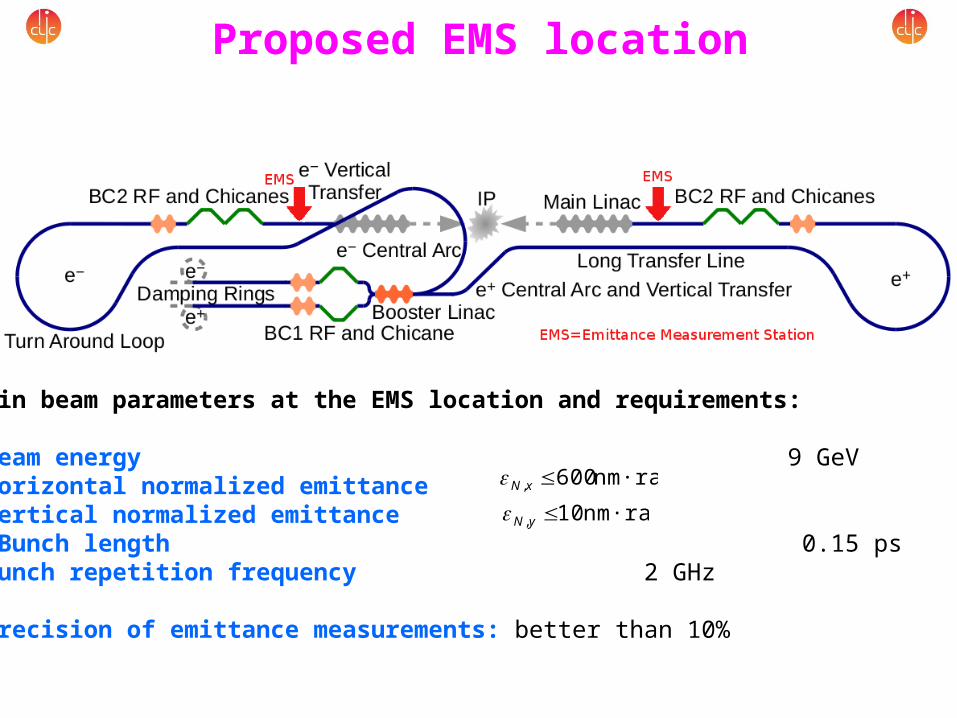
Proposed EMS location
Main beam parameters at the EMS location and requirements:
•Beam energy 9 GeV•Horizontal normalized emittance•Vertical normalized emittance• Bunch length 0.15 ps•Bunch repetition frequency 2 GHz
•Precision of emittance measurements: better than 10%
nm·rad 10, yNnm·rad 600, xN
4CLIC Workshop 2013
Emittance measurement scheme
29/01/2013
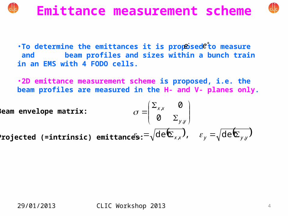
•To determine the emittances it is proposed to measure and beam profiles and sizes within a bunch train in an EMS with 4 FODO cells.
•2D emittance measurement scheme is proposed, i.e. the beam profiles are measured in the H- and V- planes only.
ee
yyyxxx
yy
xx
,,
,
,
det ,det
00
Beam envelope matrix:
Projected (=intrinsic) emittances:
CLIC Workshop 2013 529/01/2013
440
2343403433330
23333
2202121201211110
21111
0
2
2
),...,2,1( ,
iiiii
iiiii
Tiii
RRRR
RRRR
NiRR
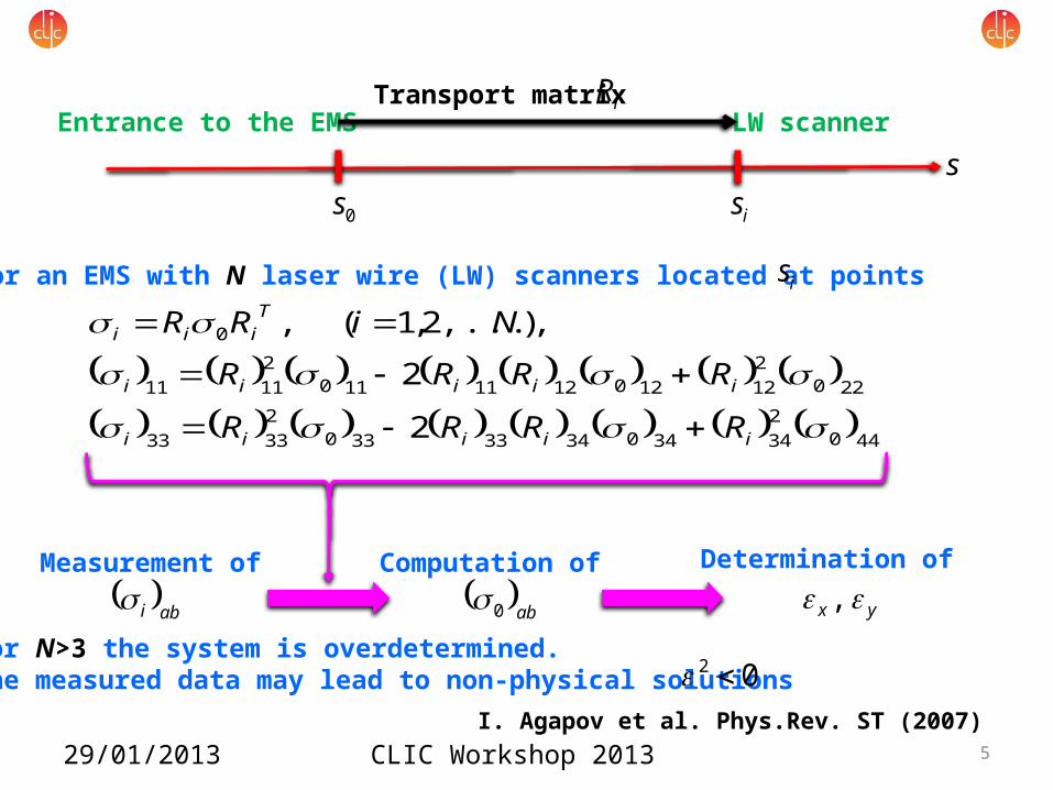
• For an EMS with N laser wire (LW) scanners located at points is
0s iss
LW scannerEntrance to the EMSiRTransport matrix
Measurement of Computation of Determination of abi ab0 yx ,
• For N>3 the system is overdetermined. • The measured data may lead to non-physical solutions 02
I. Agapov et al. Phys.Rev. ST (2007)
CLIC Workshop 2013 629/01/2013
2D emittance measurement scheme vs. 4D emittance measurement scheme:
•Advantages of the 2D scheme: - Each monitor measures only x- or y-beam size, no beam scan along a rotated axis is needed - Far less non-physical solutions are generated •Drawbacks of the 2D scheme: - The beam at the entrance must be uncoupled, so a skew correction section must be added (L ~ 120m)
CLIC Workshop 2013 7
EMS optics and simulations
29/01/2013
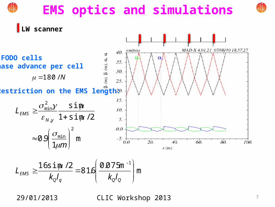
LW scanner
•4 FODO cells•Phase advance per cell
• Restriction on the EMS length:
N/180
m 1
9.0
2/sin1sin
2
min
,
2min
m
LyN
EMS
m m 075.06.812/sin16 -1
QQqQEMS lklkL
CLIC Workshop 2013 8
EMS optics and simulations
29/01/2013
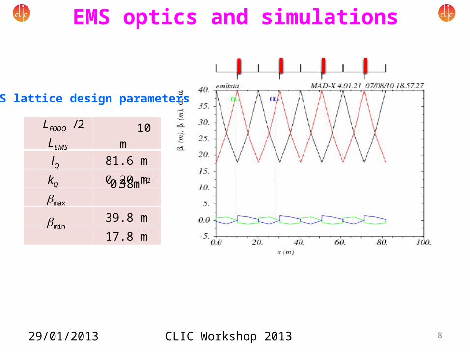
EMS lattice design parameters
10 m
81.6 m
0.20 m
39.8 m
17.8 m
2/FODOL
QlEMSL
min
Qk
max
-2m 38.0
CLIC Workshop 2013 9
EMS optics and simulations
29/01/2013
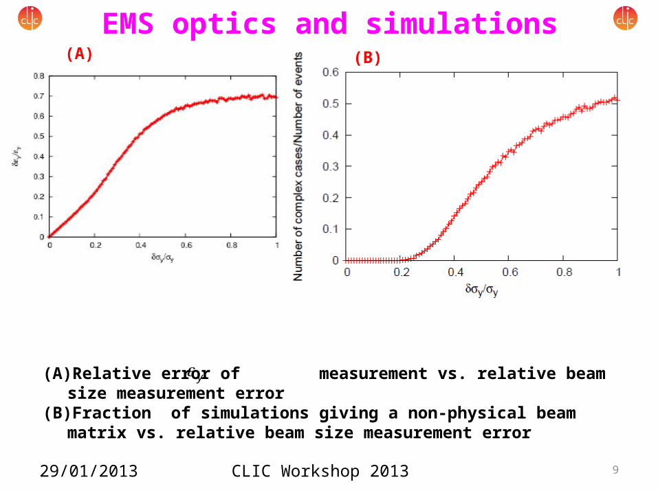
(A) (B)
(A) Relative error of measurement vs. relative beam size measurement error(B) Fraction of simulations giving a non-physical beam matrix vs. relative beam size
measurement error
y
CLIC Workshop 2013 10
EMS optics and simulations
29/01/2013
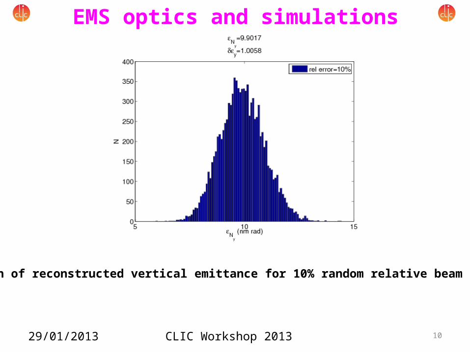
Distribution of reconstructed vertical emittance for 10% random relative beam size errors
CLIC Workshop 2013 11
New EMS simulation
29/01/2013
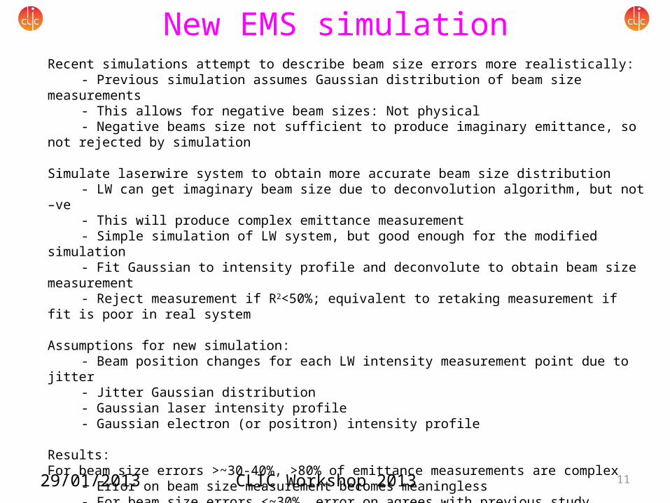
Recent simulations attempt to describe beam size errors more realistically:- Previous simulation assumes Gaussian distribution of beam size measurements- This allows for negative beam sizes: Not physical- Negative beams size not sufficient to produce imaginary emittance, so not rejected by simulation
Simulate laserwire system to obtain more accurate beam size distribution- LW can get imaginary beam size due to deconvolution algorithm, but not –ve- This will produce complex emittance measurement- Simple simulation of LW system, but good enough for the modified simulation- Fit Gaussian to intensity profile and deconvolute to obtain beam size measurement- Reject measurement if R2<50%; equivalent to retaking measurement if fit is poor in real system
Assumptions for new simulation:- Beam position changes for each LW intensity measurement point due to jitter- Jitter Gaussian distribution- Gaussian laser intensity profile- Gaussian electron (or positron) intensity profile
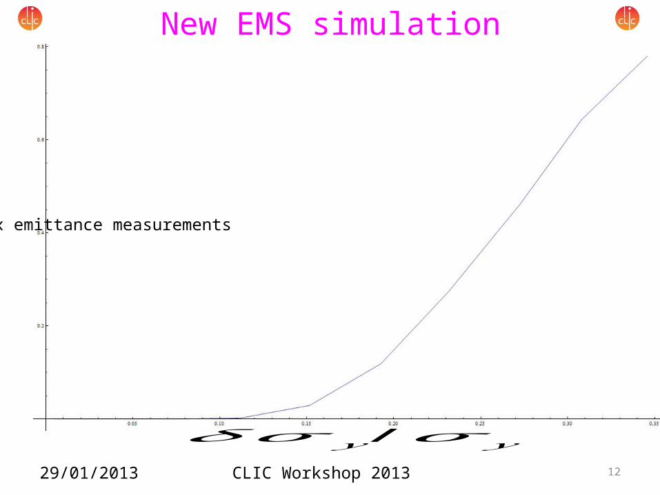
Results:For beam size errors >~30-40%, >80% of emittance measurements are complex
- Error on beam size measurement becomes meaningless- For beam size errors <~30%, error on agrees with previous study- However number of unphysical results do not agree
CLIC Workshop 2013 12
New EMS simulation
29/01/2013
𝛿𝜎 𝑦 /𝜎 𝑦
Frac
tion
of c
ompl
ex e
mitt
ance
mea
sure
men
ts
CLIC Workshop 2013 13
LW beam profile monitor proposal
29/01/2013
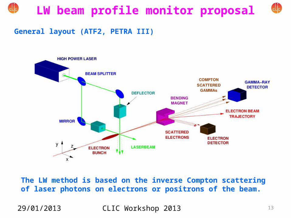
General layout (ATF2, PETRA III)
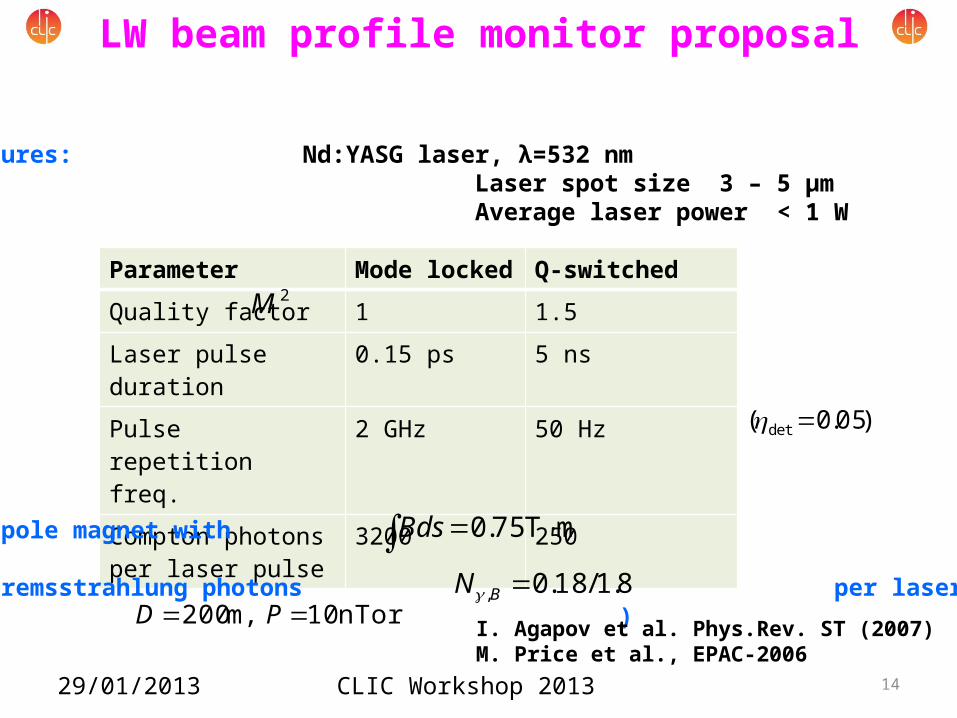
The LW method is based on the inverse Compton scattering of laser photons on electrons or positrons of the beam.
CLIC Workshop 2013 14
Parameter Mode locked Q-switched
Quality factor 1 1.5
Laser pulse duration 0.15 ps 5 ns
Pulse repetition freq. 2 GHz 50 Hz
Compton photons per laser pulse
3200 250
LW beam profile monitor proposal
29/01/2013
Main features: Nd:YASG laser, λ=532 nm Laser spot size 3 – 5 µm Average laser power < 1 W
2M
•Bending dipole magnet with
•Beam-gas bremsstrahlung photons per laser pulse(for )
mT 75.0 Bds8.1/18.0, BN
nTorr 10 m, 200 PD
)05.0( det
I. Agapov et al. Phys.Rev. ST (2007)M. Price et al., EPAC-2006
CLIC Workshop 2013 15
LW beam profile monitor proposal
29/01/2013
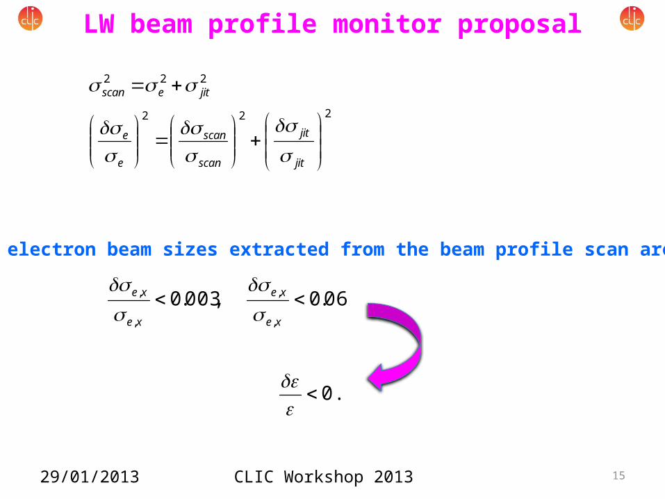
The electron beam sizes extracted from the beam profile scan are
222
222
jit
jit
scan
scan
e
e
jitescan
06.0 ,003.0,
,
,
, xe
xe
xe
xe
0.1
CLIC Workshop 2013 16
Concluding remarks
29/01/2013
•Emittance measurements with the required precision using the LW method seem to be feasible. •More detailed error study is necessary. •Estimates of contributions of other effects (e.g. of the synchrotron radiation background) have to be added. •Calculations for the EMS at other locations are missing.