RTC-8030 - CraneDude · RTC– 8030 Series II Upper Structure Boom Patented Design Boom side plates...
51
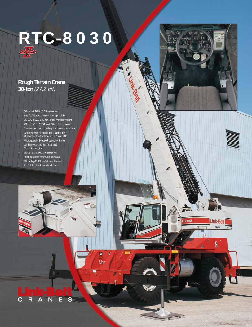
• 30-ton at 10 ft (3.05 m) radius • 143 ft (43.62 m) maximum tip height • 55,526 lb (25 186 kg) gross vehicle weight • 29 ft to 91 ft (8.84 m-27.84 m) full power, four-section boom with quick reeve boom head • Optional two-piece (bi-fold) lattice fly, stowable offsettable to 2°, 20° and 40° • Microguard 434 rated capacity limiter • Off-highway 152 hp (113 kW) Cummins engine • Spicer six speed transmission • Pilot-operated hydraulic controls • 25 mph (40.19 km/h) travel speed • 11 ft 5 in (3.48 m) wheel base Rough Terrain Crane 30-ton (27.2 mt) RTC-8030
Transcript of RTC-8030 - CraneDude · RTC– 8030 Series II Upper Structure Boom Patented Design Boom side plates...
• 30-ton at 10 ft (3.05 m) radius• 143 ft (43.62 m) maximum tip height• 55,526 lb (25 186 kg) gross vehicle weight • 29 ft to 91 ft (8.84 m-27.84 m) full power,
four-section boom with quick reeve boom head• Optional two-piece (bi-fold) lattice fly,
stowable offsettable to 2°, 20° and 40°• Microguard 434 rated capacity limiter• Off-highway 152 hp (113 kW)
Cummins engine• Spicer six speed transmission• Pilot-operated hydraulic controls• 25 mph (40.19 km/h) travel speed • 11 ft 5 in (3.48 m) wheel base
Rough Terrain Crane30-ton (27.2 mt)
RTC-8030

Operator cab features• Large front window for excellent visibility• Tinted glass• Sliding right side and rear windows and
swing-up top window provide excellentventilation
• Integral rated capacity limiter aids theoperator in safe and efficient operation bycontinuously monitoring boom length, boomangle, head height, radius of load, machineconfiguration, allowed load and percent ofallowed load.
Powerful hydraulics• For greater productivity and control,
the three pump system allows positiveprecise control
• Gear motor hydraulic hoist system deliversdependable hoisting. Matched sized main(front) and auxiliary (rear) winches providemaximum available line pulls of 11,948 lbs(5 419.5kg) and maximum line speeds of452 fpm (138 m/min) on grooved drums.
Job site maneuverability• CALC — Outrigger beams have three lifting
stages (retracted, intermediate and fullyextended) providing lifting capacities in con-fined areas.
• Steering modes are chosen and performedwith the steering wheel and include inde-pendent front steer, four wheel steer, and"crab" steering.
Invest in a legacy ofoutstanding customer support• Distributor support personnel - Factory-
trained technicians are specifically tested toestablish proficiency in all aspects of cranediagnostics and repair.
• Factory product support team - Supportingyour trained distributor personnel are experi-enced factory advisors with comprehensiverecords and technical libraries that standready to resolve any crane service issue.
• Parts Distribution Center - 72,000 sq. ft.Parts Distribution Center averages an over-90% parts availability rate.
• eParts - Link-Belt’s online computersystem links our distributors worldwideso customers can order genuine Link-Beltparts 24 hours a day, 7 days a week.
• Link-Belt Preferred - Link-Belt’s customerweb site provides instant access to a com-prehensive library of all parts, service andoperator manuals plus other technical andsales information.
Engine hood designprovides easy accessfor maintenance.
The RTC-8030 Series II is atime-honored combinationof reliability & capacityperformance!• Cummins 6BT 5.9 L Diesel Engine with
152 hp (113 kW) provides414 lb-ft (561 Nm) of torque
• Two automotive-style batteries linked inparallel provide 700 cold cranking ampseach for cold weather starting
• 4- Link rear suspension greatly reducesthe inherent bouncing at speed
• Flat deck carrier ensures that the craneis very user friendly when entering and exiting the cab
• Rugged, lightweight aluminumpontoons
• Hydraulic disc brakes for bothservice brakes and parking brake
• Metri-Pak wire harnesses have sealedrelays and connectors throughout foroutstanding long-term reliability. All wireshave flame retardant polyethylene insula-tion, resulting in a higher heat resistantwiring system.
4-section full power boomwith attachment flexibility• Full power 29ft to 91ft (8.84-27.84m)
four-section boom with two extendmodes: A-max and fully synchronized
• Features the "Boss,"Link-Belt’s patentedboom design of highstrength angle cords andhigh formability sidewall embossments.
• Optional 25ft (7.62m) one piece stow-able lattice fly. Maximum tip height is124ft (37.99m)
• Optional 27ft (8.23m) one piece latticefly, stowable, offsetable to 2°, 20°. and40°. Maximum tip height is 126ft(38.51m)
• Optional 27ft-44ft (8.23-13.41m) twopiece bi-fold lattice fly, stowable, off-setable to 2°, 20°. and 40°. Maximumtip height is 143ft (43.62m)
® Link-Belt is a registered trademark. Copyright 2005. All rightsreserved. We are constantly improving our products and thereforereserve the right to change designs and specifications.
Litho in U.S.A. 3/05 #4306 (supersedes #4279)
A-max extends only theinner-mid section of theboom for substantiallyincreased capacitiesfor in-close, maximumcapacity lifts.
RTC-8030Rough Terrain Crane
Loaded withproven innovationsfor awesomeperformance,control & reliability

Litho in USA 3/03 #5375 (Supersedes #5333)
SpecificationsTelescopic Boom Rough Terrain Crane
RTC–8030 30–ton (27.2 metric tons)���������
Tailswing of Counterweight 9’ 11.5” 3.04
Turning radius (4–wheel steer 17’ 1” 5.21
centerline of tires)
Turning radius (2–wheel steer 31” 3” 9.55
centerline of tires)
Turning radius (4–wheel steer outside 20’ 8.5” 6.31
front carrier corner)
Turning radius (2–wheel steer outside 35’ 10.67
front carrier corner)
9’–111/2” (3.04 m)Counterweight
Tailswing
4’–3”(1.30 m)
Three Section 30’–0” (9.14 m)
18�
24�22�
13�
6’–10 5/16”(2.09 m)
7’–6 1/4”(2.29 m)
11’–9/16”(3.37 m)
Four Section 29’–0” (8.84 m)
C of RotationL
2’–1 1/2”(0.65 m)
5’–11”(1.80 m)
10’–2 5/16”(3.11 m)
22’–7”(6.89 m)
5’–6”(1.68 m)
9’–4 11/16”(2.86 m)
5’–3”(1.60 m)
Three Section7’–2” (2.18 m)
@ 0� Boom Angle
Four Section11’–1 5/16” (3.39 m)@ 0� Boom Angle
Three section37’–1 3/8” (11.31 m)@ 0� Boom Angle
Four section38’–1 3/8” (11.62 m)@ 0� Boom Angle
Intermediate Extension
Full Retraction
19’ 6” (5.94 m)
��������������� ��� �����
Full Extension
��������
Three Section11’–0” (3.35 m)
@ 0� Boom Angle
Four Section7’–4” (2.26 m)
@ 0� Boom Angle
8” (0.2 m)
6’ 8.25” (2.04 m)
7’ 10” (2.39 m)
C of Tires
8’ 6” (2.59 m)
L
11 15/16”(0.3 m)
2’ 0”(0.61 m)
Link–Belt
13’ 8” (4.17 m)

���RTC–8030 Series II
Upper Structure� BoomPatented Design� Boom side plates have diamond shaped
impressions for superior strength toweight ratio and 100,000 p.s.i. (689.5MPa) steel angle chords for lateral stiff-ness.
� Boom telescope sections are supportedby top, bottom and adjustable side wearshoes to prevent metal to metal contact.
Standard Boom� 30’ – 78’ (9.14 – 23.78 m) three–section
full power boom.� Mechanical Boom Angle Indicator
Optional Boom� 29’ – 91’ 4” (8.84 – 27.84 m) four–
section full power boom. Two mode boom extension:� Basic mode (or mode ’B’) is the full
power, synchronized mode of telescop-ing all sections proportionally.
� The exclusive A–max mode (or mode‘A’) extends only the inner mid–sectionto 49’ 9” (15.16 m) offering increased capacities for in–close, maximum capacity picks.
� Mechanical Boom Angle Indicator
Boom Head� Four 10.63” (0.27 m) root diameter steel
sheaves handle up to eight parts of wirerope.
� Quick reeve design.� Rope dead end lugs provided on each
side of boom head.� Easily removable wire rope guards.� Fly pinning alignment tool.
Boom Elevation� One Link–Belt designed hydraulic cylinder
with holding valve and bushing in each end.� Hand control for controlling boom
elevation from –3 to 78�.
Optional Auxiliary Lifting Sheave� Single 10.63” (0.27 m) root diameter steel
sheave with removable wire rope guard.� Use with one or two parts of line off the
optional front winch.� Does not affect erection of fly or use of
main head sheaves for multiple reeving.
Optional� 30–ton (27.2 mt) 3–sheave, quick reeve
hook block.� 8.5–ton (7.7 mt) hook ball.� Boom floodlight
� FlyOptional� 25’ (7.62 m) fixed stowable one–piece lat-
tice type.� 27’ (8.23 m) offsettable stowable one–
piece lattice type with lugs to allow foraddition of second section. Can be offset2�, 20� or 40�.
� 27’ – 44’ (8.23 to 13.41 m) offsettablestowable two–piece lattice type. Can beoffset 2�, 20� or 40�.
� Cab and ControlsEnvironmental Cab� Isolated from sound and vibration by a
neoprene seal.� Six–way adjustable operator’s seat with
retractable seat belt.� Four–way adjustable tilting–telescoping
and locking steering wheel.� All windows are tinted and tempered
safety glass.� Slide by door opens to 36” (0.91 m) width.� Sliding rear and right side windows and
swing up roof windows for maximum visibility and ventilation.
� Engine dependent warm–water heaterwith defroster.
� Audible swing alarm. � Warning horn� Backup alarm � Travel lights� 12–volt accessory outlet � Sun screen� Electric windshield wiper � Mirrors� Top hatch window wiper � Cup holder� Fire extinguisher � Circulating fan
Optional� Amber strobe light� Emergency steering system� Amber rotating beacon
ControlsHydraulic controls (single–axis type) for:� Main winch � Boom hoist� Optional auxiliary winch � Swing� Drum rotation indicators
Foot controls for:� Boom telescope� Swing brake� Engine throttle with throttle lock� Outrigger controls and sight level bubble
also provided in upper cab.
Cab InstrumentationDash mounted gauges for:� Hydraulic oil temperature� Tachometer� Convertor temperature � Voltmeter� Oil pressure � Fuel� Water temperature� Audio/Visual warning system
� Rated Capacity Limiter� Microguard 434 Graphic audio–visual
warning system built into dash with anti–two block and function limiters.
Operating data available includes:� Machine configuration.� Boom length � Boom angle� Head height � Radius of load� Allowed load � Actual load� % of allowed load
Presettable alarms include:� Maximum and minimum boom angles.� Maximum tip height.� Maximum boom length.� Swing left/right positions.
� Operator defined area alarm is standard.� Anti–two block weight designed for quick
reeve of hookblock.
Optional� Internal RCL light bar: Visually informs
operator when crane is approaching maxi-mum load capacity with a series of threelights; green, yellow and red.
� External RCL light bar: Visually informsground crew when crane is approachingmaximum load capacity kickouts and pre-settable alarms with a series of threelights; green, yellow and red.
� Swing� Bi–directional hydraulic swing motor
mounted to a planetary reducer for 360�continuous smooth swing at 2.8 r.p.m.
� Swing park brake – 360� mechanicaldisc brake mounted on the speed reducer.Mechanically controlled from the controlconsole.
� Swing brake – 360�, foot operated,spring released disc brake mounted onthe speed reducer.
� Swing lock – Standard; two position trav-el lock operated from the operator’s cab.
� Counterweight – Bolted to upper struc-ture frame.� Three–Section – 7,800 lbs. (3 538 kg).� Four–Section – 9,300 lbs. (4 218 kg).
Optional� 360� swing lock (meets New York City
requirements).
� Hydraulic SystemMain Pump� 2–section gear–type pump.� Combined pump capacity 75 gpm (284
lpm)� Mounted on transmission converter, pow-
ered by engine.� Pump operates at 3,500 p.s.i. (24.1 MPa)
maximum system pressure.� O–Ring Face Seal (ORFS) technology
throughout with hydraulic oil cooler.
Telescope / Outrigger / Steering Pump –� Single gear–type pump, 18 gpm (83.2
lpm) maximum. Mounted on engine,powered by engine through a direct me-chanical drive.
� Pump operates at 3,000 p.s.i. (20.7 MPa)maximum system pressure.
Reservoir� 80 gal. (303 L) capacity. Diffuser for deaera-
tion.
Filtration:� Two 10–micron filters located outside hy-
draulic reservoir.� Accessible for easy replacement.
(Continued on next page)

RTC–8030 Series II–3–
(Upper Structure continued)
Control Valves:� Five separate, pilot operated control
valves allow simultaneous operation of allcrane functions.
Optional� Pump disconnect.
� Load Hoist SystemStandard� 2M rear winch with grooved lagging.� Two–speed motor and automatic brake.
� Power up/down mode of operation.� Controls for future addition of auxiliary
winch.� Bi–directional gear–type hydraulic motor,
driven through a planetary reduction unitfor positive operator control under all loadconditions.
� Asynchronous parallel double crossovergrooved drums minimize rope harmonic motion.
� 6 x 19 IWRC wire rope.
Line Pulls and Speeds� Maximum line pull 11,948 lbs. (5 420 kg)
and maximum line speed of 452 f.p.m.(138 m/min) on standard 10.63” (0.27 m)root diameter grooved drum.
Optional� 2M front winch with two–speed motor and
automatic brake, power up/down mode of operation.
� Hoist drum cable followers.� Third wrap indicators.� Rotation resistant rope.
Carrier� Type� 8’ 6” (2.59 m) wide, 137” (3.48 m) wheel-
base.� 4 x 4 x 4 – (4–wheel steer, 4–wheel drive)
For rough terrain with limited turning area.
Frame� 100,000 p.s.i. (689.5 MPa) steel, double
walled construction.� Integral 100,000 p.s.i. (689.5 MPa) steel
outrigger boxes.
Standard Carrier Equipment� Two front, two rear and two mid–point
carrier steps.� Non–slip safety strips on carrier deck.� Two deep front storage units.� Fenders.� Pontoon storage.� Full lighting package.� Front towing shackles.� Hook block tie back.
Optional� Front and rear mounted pintle hook.
� EngineEngine Cummins 6BT 5.9 L
Cylinders – cycleBoreStrokeDisplacementMaximum brake hpPeak torque (ft. lb.)Electric systemStarting systemFuel capacityAlternatorCrankcase capacity(total system)
6 – 44.02 in. (102.11 mm)4.72 in. (119.89 mm)359 cu. in. (5 883 cm3)152 @ 2,500 rpm414 @ 1,500 rpm12 volt12 volt75 gallons (283.9 L)130 amps17.3 qts. (16.37 L)
� Water/fuel separator on engine� 110–volt block heater� �ther injection package – optional
� Transmission� Clark three–speed two range power shift
transmission.� Six speeds forward and two reverse� Front axle disconnect for two or four–
wheel drive.
� Axles� Heavy duty planetary drive/steer type.� Front axle disconnect.
� SuspensionFront Axle� Rigid mounted to frame.
Rear Axle� Fully independent 4–Link.� Automatic axle oscillation lockout cylin-
ders engage when upper structure rotatespast 2.5� of centerline.
Optional� Rear Hydro–gas Ride�
� Steering� Hydraulic two–wheel, four–wheel and
“crab” steering.� Modes selected by toggle switch on dash.� All modes fully controlled by steering
wheel.
Optional� Rear steer indicator
� TiresFront and Rear� Standard 20.5R25 (24–PR) Loader type.
Optional� Spare tires and rims
� BrakesService� Fully hydraulic disc–type brakes at each
wheel end with independent front and rearsystem.
Parking/Emergency� Spring applied, hydraulic released, cab
controlled, disc–type integral to the trans-mission.
� Outriggers� Three position operation capability.� Four hydraulic, telescoping beam and
jack outriggers.� Vertical jack cylinders equipped with
integral holding valve.� Beams extend to 19’ 6” (5.94 m) center-
line–to–centerline and retract to within 8’6” (2.59 m) overall width.
� Equipped with stowable, lightweight 18.5”(0.47 m) diameter aluminum floats.
� Dash mounted controls and sight levelbubble located in upper structure cab.
Confined Area Lifting Capacities(CALC�) System� The crane is operational in one of the
three outriggers positions and operationalin confined areas in two positions (inter-mediate and full retraction. The three outrigger positions are:
� Full extension – 21.63’ (6.42 m)� Intermediate position – 13’ 8” (4.17 m).� Full retraction – 7’ 10” (2.39 m).� Capacities are available with the outrigger
beams in the intermediate and full retrac-tion positions.
� When the outrigger position levers (lo-cated on the outrigger beams) are en-gaged, the operator can set the crane inthe intermediate or full retraction outriggerposition without having to leave the cab.
� Travel Speeds and Gradability
Tires 20.5R25
Maximum Speed 24.8 (39.9 km/h)
Gradability at stall 198.9%
Maximum TractiveEffort at Stall
46,769 lbs. (21 214 kg)
Gradability at 1.0mph (1.6 km/hr)
76.8%
Maximum TractiveEffort at 1.0 mph.(1.6 km/hr)
32,214 lbs. @ 1,500rpm (14 612 kg)

���RTC–8030 Series II
� Axle LoadsBase machine with standard 30 to 78’(9.14 – 23.78 m) three–section boom, �
Upper facing front Upper facing rear(9.14 – 23.78 m) three–section boom,2M main winch with 2–speed hoistingand power up/down, 450’. (137 m) of
G.V.W.�Front axle Rear axle Front axle Rear axle
5/8” in. (19 mm) wire rope. 4x4x4 carrier with Cummins 6BT5.9 engine,20.5R25 tires 75 gals. (283.91 L) of
lbs. kg. lbs. kg. lbs. kg. lbs. kg. lbs. kg.20.5R25 tires 75 gals. (283.91 L) offuel, tow shackles and hook block tie-back. 52,098 23 631 25,907 11 751 26,191 11 880 23,338 10 586 28,760 13 045
Pintle hook, front and rear 26 12 13 6 13 6 13 6 13 6
Cold weather starting aids – ether injector 6 3 0 0 6 3 0 0 6 3
Pump disconnect 28 13 6 3 21 10 6 3 21 10
Air conditioning in operator’s cab 215 98 36 16 179 81 187 85 28 13
Emergency steer system 5 2 3 1 2 1 2 1 3 1
360 degree sector gear–type houselock 60 27 29 13 31 14 33 15 27 12
Winch roller – rear winch 76 34 –14 –6 90 41 93 42 –17 –8
Power up/down winch with 450 ft. ofrope –front 361 164 –28 –13 389 176 402 182 –41 –19
Winch roller – front winch 76 36 1 0 75 34 78 35 –2 –1
Remove 450’ (137 m) of wire rope fromrear winch –320 –145 82 37 –402 –182 –413 –187 94 43
Remove 450’ (137 m) of wire rope fromfront winch –320 –145 21 10 –340 –154 –352 –160 33 15
Replace three–section boom with foursection boom 3,428 1 555 1,654 750 1,774 805 1,900 862 1528 693
30–ton (27.2 mt) capacity hook block tocarrier storage box 670 304 943 428 –273 –124 –248 –112 918 416
8.5–ton (7.7 mt) capacity hook block tocarrier storage box 360 163 506 230 –146 –66 –133 –60 493 225
Three–Section Boom
Fly brackets to boom base sections forfly options 140 64 213 97 –72 –33 –67 –30 208 94
25’ (7.62 m) fixed fly (stowed) 535 243 860 390 –325 –147 –306 –139 841 381
27’ (8.23 m) offset fly (stowed) 1,052 477 1793 813 –741 –336 –703 –319 1,755 796
27 – 44’ (8.23 – 13.41 m) offset fly(stowed) 1,475 669 2314 1050 –839 –381 –785 –356 2,260 1025
Floodlight to boom base section 4 2 7 3 –3 –1 –3 –1 7 3
Auxiliary lifting sheave 71 32 204 93 –132 –60 –130 –59 201 91
Four–Section Boom
Fly brackets to boom base sections forfly options 140 64 200 91 –60 –27 –55 –25 195 88
25’ (7.62 m) fixed fly (stowed) 535 243 813 369 –278 –126 –259 –117 794 360
27’ (8.23 m) offset fly (stowed) 1,052 477 1701 772 –649 –294 –611 –277 1,663 754
27 – 44’ (8.23 – 13.41 m) offset fly(stowed) 1,475 669 2184 991 –710 –322 –656 –298 2,131 967
Floodlight to boom base section 4 2 7 3 –3 –1 –3 –1 7 3
Auxiliary lifting sheave 71 32 197 82 –126 –57 –124 –56 195 88
� – Adjust gross weight and axle loading according to component weight. Note: All weights are � 3%.
Link–Belt Construction Equipment Company Lexington, Kentucky www.linkbelt.com�Link–Belt is a registered trademark. Copyright 2003. All rights reserved. We are constantly improving our products and therefore reserve the right to change designs and specifications.

15474 (supersedes 5435)---0506---E8
RTC---8030 IILink-Belt Cranes
Technical DataSpecifications & Capacities
Telescopic Boom Rough Terrain Crane30 ton (27.2 metric ton)
CAUTION: This material is supplied forreference use only. Operator must refer toin---cab Crane RatingManual andOperator’sManual to determine allowable crane liftingcapacities and assembly and operatingprocedures.

5474 (supersedes 5435)---0506---E8
RTC---8030 II Link-Belt Cranes

5474 (supersedes 5435)---0506---E8
RTC---8030 IILink-Belt Cranes
Table Of ContentsBoom, Attachments, and Upper Structure 1. . . . . . . . . . . . . . . . . . . . . . . . . . . . . . . . . . . . . . . . . . . . . . . . . . . .Boom 1. . . . . . . . . . . . . . . . . . . . . . . . . . . . . . . . . . . . . . . . . . . . . . . . . . . . . . . . . . . . . . . . . . . . . . . . . . . . . . . . . . . .Boom Head 1. . . . . . . . . . . . . . . . . . . . . . . . . . . . . . . . . . . . . . . . . . . . . . . . . . . . . . . . . . . . . . . . . . . . . . . . . . . . .Boom Elevation 1. . . . . . . . . . . . . . . . . . . . . . . . . . . . . . . . . . . . . . . . . . . . . . . . . . . . . . . . . . . . . . . . . . . . . . . . . .Auxiliary Lifting Sheave --- Optional 1. . . . . . . . . . . . . . . . . . . . . . . . . . . . . . . . . . . . . . . . . . . . . . . . . . . . . . . . .Hook Blocks and Balls --- Optional 1. . . . . . . . . . . . . . . . . . . . . . . . . . . . . . . . . . . . . . . . . . . . . . . . . . . . . . . . . .Fly --- Optional 1. . . . . . . . . . . . . . . . . . . . . . . . . . . . . . . . . . . . . . . . . . . . . . . . . . . . . . . . . . . . . . . . . . . . . . . . . . .Operator’s Cab and Controls 1. . . . . . . . . . . . . . . . . . . . . . . . . . . . . . . . . . . . . . . . . . . . . . . . . . . . . . . . . . . . . . . .Swing 2. . . . . . . . . . . . . . . . . . . . . . . . . . . . . . . . . . . . . . . . . . . . . . . . . . . . . . . . . . . . . . . . . . . . . . . . . . . . . . . . . . . .Electrical 2. . . . . . . . . . . . . . . . . . . . . . . . . . . . . . . . . . . . . . . . . . . . . . . . . . . . . . . . . . . . . . . . . . . . . . . . . . . . . . . . .Load Hoist System 3. . . . . . . . . . . . . . . . . . . . . . . . . . . . . . . . . . . . . . . . . . . . . . . . . . . . . . . . . . . . . . . . . . . . . . . . .Load Hoist Performance 3. . . . . . . . . . . . . . . . . . . . . . . . . . . . . . . . . . . . . . . . . . . . . . . . . . . . . . . . . . . . . . . . . . .2M Main and Optional Auxiliary Winches 3. . . . . . . . . . . . . . . . . . . . . . . . . . . . . . . . . . . . . . . . . . . . . . . . . . . .Hydraulic System 3. . . . . . . . . . . . . . . . . . . . . . . . . . . . . . . . . . . . . . . . . . . . . . . . . . . . . . . . . . . . . . . . . . . . . . . . . .Counterweight 3. . . . . . . . . . . . . . . . . . . . . . . . . . . . . . . . . . . . . . . . . . . . . . . . . . . . . . . . . . . . . . . . . . . . . . . . . . . .Carrier 4. . . . . . . . . . . . . . . . . . . . . . . . . . . . . . . . . . . . . . . . . . . . . . . . . . . . . . . . . . . . . . . . . . . . . . . . . . . . . . . . . . . .General 4. . . . . . . . . . . . . . . . . . . . . . . . . . . . . . . . . . . . . . . . . . . . . . . . . . . . . . . . . . . . . . . . . . . . . . . . . . . . . . . . . . .Outriggers 4. . . . . . . . . . . . . . . . . . . . . . . . . . . . . . . . . . . . . . . . . . . . . . . . . . . . . . . . . . . . . . . . . . . . . . . . . . . . . . . .Steering and Axles 4. . . . . . . . . . . . . . . . . . . . . . . . . . . . . . . . . . . . . . . . . . . . . . . . . . . . . . . . . . . . . . . . . . . . . . . . .Suspension 4. . . . . . . . . . . . . . . . . . . . . . . . . . . . . . . . . . . . . . . . . . . . . . . . . . . . . . . . . . . . . . . . . . . . . . . . . . . . . . .Tires and Wheels 4. . . . . . . . . . . . . . . . . . . . . . . . . . . . . . . . . . . . . . . . . . . . . . . . . . . . . . . . . . . . . . . . . . . . . . . . . .Brakes 4. . . . . . . . . . . . . . . . . . . . . . . . . . . . . . . . . . . . . . . . . . . . . . . . . . . . . . . . . . . . . . . . . . . . . . . . . . . . . . . . . . .Electrical 4. . . . . . . . . . . . . . . . . . . . . . . . . . . . . . . . . . . . . . . . . . . . . . . . . . . . . . . . . . . . . . . . . . . . . . . . . . . . . . . . .Engine 4. . . . . . . . . . . . . . . . . . . . . . . . . . . . . . . . . . . . . . . . . . . . . . . . . . . . . . . . . . . . . . . . . . . . . . . . . . . . . . . . . . .Transmission 4. . . . . . . . . . . . . . . . . . . . . . . . . . . . . . . . . . . . . . . . . . . . . . . . . . . . . . . . . . . . . . . . . . . . . . . . . . . . . .Carrier Speeds and Gradeability 5. . . . . . . . . . . . . . . . . . . . . . . . . . . . . . . . . . . . . . . . . . . . . . . . . . . . . . . . . . . . .Fuel Tank 5. . . . . . . . . . . . . . . . . . . . . . . . . . . . . . . . . . . . . . . . . . . . . . . . . . . . . . . . . . . . . . . . . . . . . . . . . . . . . . . . .Hydraulic System 5. . . . . . . . . . . . . . . . . . . . . . . . . . . . . . . . . . . . . . . . . . . . . . . . . . . . . . . . . . . . . . . . . . . . . . . . . .Pump Drive 5. . . . . . . . . . . . . . . . . . . . . . . . . . . . . . . . . . . . . . . . . . . . . . . . . . . . . . . . . . . . . . . . . . . . . . . . . . . . . . .Axle Loads 6. . . . . . . . . . . . . . . . . . . . . . . . . . . . . . . . . . . . . . . . . . . . . . . . . . . . . . . . . . . . . . . . . . . . . . . . . . . . . . . .General Dimensions 7. . . . . . . . . . . . . . . . . . . . . . . . . . . . . . . . . . . . . . . . . . . . . . . . . . . . . . . . . . . . . . . . . . . . . . . .Working Range Diagram 8. . . . . . . . . . . . . . . . . . . . . . . . . . . . . . . . . . . . . . . . . . . . . . . . . . . . . . . . . . . . . . . . . . . .Boom Extend Modes 9. . . . . . . . . . . . . . . . . . . . . . . . . . . . . . . . . . . . . . . . . . . . . . . . . . . . . . . . . . . . . . . . . . . . . . .Main Boom Lift Capacity Charts -- Standard 10. . . . . . . . . . . . . . . . . . . . . . . . . . . . . . . . . . . . . . . . . . . . . . . . .Fully Extended Outriggers --- 360˚ Rotation 10. . . . . . . . . . . . . . . . . . . . . . . . . . . . . . . . . . . . . . . . . . . . . . . . . . .On Tires --- Stationary --- Boom Centered Over Front Between Tire Tracks 11. . . . . . . . . . . . . . . . . . . . . . . . .On Tires --- Pick & Carry (Creep) --- Boom Centered Over Front 11. . . . . . . . . . . . . . . . . . . . . . . . . . . . . . . . . .On Tires --- Stationary --- 360˚ Rotation 11. . . . . . . . . . . . . . . . . . . . . . . . . . . . . . . . . . . . . . . . . . . . . . . . . . . . . . .Fly Attachment Lift Capacity Charts -- Optional 12. . . . . . . . . . . . . . . . . . . . . . . . . . . . . . . . . . . . . . . . . . . . . . .Fully Extended Outriggers --- 360˚ Rotation 12. . . . . . . . . . . . . . . . . . . . . . . . . . . . . . . . . . . . . . . . . . . . . . . . . . .91.25 ft Main Boom Length 12. . . . . . . . . . . . . . . . . . . . . . . . . . . . . . . . . . . . . . . . . . . . . . . . . . . . . . . . . . . . . . . .Fully Extended Outriggers --- 360˚ Rotation 13. . . . . . . . . . . . . . . . . . . . . . . . . . . . . . . . . . . . . . . . . . . . . . . . . . .91.25 ft Main Boom Length --- 2˚ Fly Offset 13. . . . . . . . . . . . . . . . . . . . . . . . . . . . . . . . . . . . . . . . . . . . . . . . . .91.25 ft Main Boom Length --- 20˚ Fly Offset 13. . . . . . . . . . . . . . . . . . . . . . . . . . . . . . . . . . . . . . . . . . . . . . . . .91.25 ft Main Boom Length --- 40˚ Fly Offset 13. . . . . . . . . . . . . . . . . . . . . . . . . . . . . . . . . . . . . . . . . . . . . . . . .

5474 (supersedes 5435)---0506---E8
RTC---8030 II Link-Belt Cranes
Main Boom Lift Capacity Charts -- Optional (Metric) 14. . . . . . . . . . . . . . . . . . . . . . . . . . . . . . . . . . . . . . . . . .Fully Extended Outriggers --- 360˚ Rotation 14. . . . . . . . . . . . . . . . . . . . . . . . . . . . . . . . . . . . . . . . . . . . . . . . . . .On Tires --- Stationary --- Boom Centered Over Front Between Tire Tracks 15. . . . . . . . . . . . . . . . . . . . . . . . .On Tires --- Pick & Carry (Creep) --- Boom Centered Over Front 15. . . . . . . . . . . . . . . . . . . . . . . . . . . . . . . . . .On Tires --- Stationary --- 360˚ Rotation 16. . . . . . . . . . . . . . . . . . . . . . . . . . . . . . . . . . . . . . . . . . . . . . . . . . . . . . .Fly Attachment Lift Capacity Charts -- Optional (Metric) 16. . . . . . . . . . . . . . . . . . . . . . . . . . . . . . . . . . . . . . .Fully Extended Outriggers --- 360˚ Rotation 16. . . . . . . . . . . . . . . . . . . . . . . . . . . . . . . . . . . . . . . . . . . . . . . . . . .27.81m Main Boom Length 16. . . . . . . . . . . . . . . . . . . . . . . . . . . . . . . . . . . . . . . . . . . . . . . . . . . . . . . . . . . . . . . .Fully Extended Outriggers --- 360˚ Rotation 17. . . . . . . . . . . . . . . . . . . . . . . . . . . . . . . . . . . . . . . . . . . . . . . . . . .27.81m Main Boom Length --- 2˚ Fly Offset 17. . . . . . . . . . . . . . . . . . . . . . . . . . . . . . . . . . . . . . . . . . . . . . . . . .27.81m Main Boom Length --- 20˚ Fly Offset 17. . . . . . . . . . . . . . . . . . . . . . . . . . . . . . . . . . . . . . . . . . . . . . . . .27.81m Main Boom Length --- 40˚ Fly Offset 17. . . . . . . . . . . . . . . . . . . . . . . . . . . . . . . . . . . . . . . . . . . . . . . . .

15474 (supersedes 5435)---0506---E8
RTC---8030 IILink-Belt Cranes
Boom, Attachments, and Upper StructureJ BoomDesign --- Four section, box type construction of high ten-sile steel consisting of one base section and three tele-scoping sections. The vertical side plates have diamondshaped steel impressions for superior strength to weightration. The first telescoping section extends independentlyby means of one double---acting, single stage hydrauliccylinder with integrated holding valves. The second andthird telescoping sections extend proportionally by meansof one double---acting, single stage cylinder with integratedholding valves and cables.BoomS 29 ft---91 ft 4 in (8.84 ---27.84m) four section full powerboom
S Two mode boom extension: A---max mode provides su-perior capacities by extending the first telescoping sec-tion to 49 ft 9 in (15.16m). Standard mode synchronizesall the telescoping sections proportionally to 91 ft 4 in(27.84m). Controlled from the operator’s cab.
S Mechanical boom angle indicatorS Maximum tip height for A---max mode is 66 ft 2 in (20.2m)and standard mode is 100 ft 6 in (30.6m).Boom HeadS Four 10.63 in (27.0cm) root diameter nylon sheaves tohandle up to eight parts of line
S Easily removable wire rope guardsS Rope dead end lugs on each side of the boom headS Boom head is designed for quick---reeve of the hookblockBoom ElevationS One double acting hydraulic cylinder with integral hold-ing valve
S Boom elevation: ---3˚ to 78˚Auxiliary Lifting Sheave --- OptionalS Single 10.63 in (27.0cm) root diameter steel sheaveS Easily removable wire rope guardsS Does not affect erection of the fly or use of the main headsheavesHook Blocks and Balls --- OptionalS 30 ton (27.2mt) 3 sheave quick---reeve hook block withsafety latch
S 8.5 ton (7.7mt) swivel and non---swivel hook balls withsafety latchFly --- OptionalS 25 ft (7.62m) one piece lattice fly, stowable. Maximum tipheight is 124.63 ft (37.99m).
S 27 ft (8.23m) one piece lattice fly, stowable, offsettable to2˚, 20˚, and 40˚. Maximum tip height is 126.33 ft(38.51m).
S 27---44 ft (8.23 ---13.41m) two piece bi---fold lattice fly,stowable, offsettable to 2˚, 20˚, and 40˚. Maximum tipheight is 143.11 ft (43.62m).
J Operator’s Cab and ControlsEnvironmental Cab --- Fully enclosed, one person cab ofgalvaneal steel structure with acoustical insulation.Equipped with:S Tinted and tempered glass windowsS Large fixed front window with windshield wiper and wash-er
S Swing up roof window with windshield wiperS Sliding left side door with large fixed windowS Sliding rear and right side windows for ventilationS Six way adjustable, cushioned seat with seat beltS Engine dependent warm---water heater with air ducts forfront windshield defroster and cab floor
S 12 volt accessory outletS Bubble levelS Circulating fanS Adjustable sun visorS Dome lightS Cup holderS Fire extinguisherS MirrorsS Emergency steering system --- optionalAir Conditioning --- OptionalSteering Column --- Conventional automotive type with tiltand telescope functions for operator comfort. Steering col-umn includes the following controls and indicators:S Tilt leverS Turn signal leverS Windshield wiper and washer switchS Headlight switchS Telescoping column lockS Steering wheelS Horn buttonS Engine ignition switchS Ignition switch lockS Hazard flasher button
2 5474 (supersedes 5435)---0506---E8
RTC---8030 II Link-Belt Cranes
Armrest Controls --- Two single axis controllers or optionalsingle axis hydraulic controllers for:S SwingS Boom hoistS Main rear winchS Auxiliary front winch --- optionalS Drum rotation indicationS Drum rotation indicator activation switchS Winch high/low speed and disable switch(es)S Throttle lockS Telescopic override switchesFoot ControlsS Boom telescopeS Swing brakeS Engine throttleS Carrier service brakeDash Panel
Controls for:S Combination steeringS 4---wheel driveS Transmission gear selectionS Rated capacity limiterS Two position swing lockS Swing park brakeS Function lockoutS Outrigger systemS Upper lights --- optionalS Rotating beacon --- optionalS Ether start --- optionalS Air conditioner and heater --- optionalS Third wrap indicator activation --- optionalS Boom floodlight --- optional
Indicators for:S Service brakeS Rear wheel offset --- optionalS First layer/Third wrap --- optionalGauges for:S Fuel levelS Hydraulic oil temperatureS Voltage indicatorS Water temperatureS Engine oil pressureS TachometerS Transmission oil temperature
Rated Capacity Limiter --- Microguard 434 graphic audio---visual warning system integrated into the dash with anti ---two block and function limiter. Operating data availableincludes:S Crane configurationS Boom lengthS Boom head heightS Allowed load and % of allowed loadS Boom angleS Radius of loadS Actual loadS Operator settable alarms (include):S Maximum and minimum boom anglesS Maximum tip heightS Maximum boom lengthS Swing left/right positionsS Operator defined area (imaginary plane)Internal RCL Light Bar --- Optional --- Visually informs theoperator when crane is approaching maximum load capac-ity with a series of green, yellow, and red lights.External RCL Light Bar --- Optional --- Visually informs theground crew when crane is approaching maximum loadcapacity with a series of green, yellow, and red lights.
J SwingMotor/Planetary --- Bi ---directional hydraulic swing motormounted to a planetary reducer for 360˚ continuoussmooth swing at 2.8 rpm.Swing Park Brake --- 360˚, mechanical disc brakemounted on the speed reducer. Mechanically controlledfrom the operator’s cab.Swing Brake --- 360˚, foot operated, hydraulic applied discbrake mounted to the speed reducer.Swing Lock --- Two---position swing lock (boom over frontor rear) operated from the operator’s cab.360˚ Positive Swing Lock --- Optional --- Meets New YorkCity requirement.
J ElectricalSwing Alarm --- Audio warning device signals when theupper is swinging.LightsS Two working lights on front of the cab --- optionalS One rotating amber beacon on top of the cab --- optionalS One amber strobe beacon on top of the cab --- optionalS Boom floodlight --- optional
35474 (supersedes 5435)---0506---E8
RTC---8030 IILink-Belt Cranes
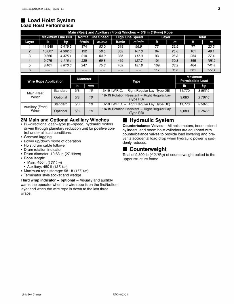
J Load Hoist SystemLoad Hoist Performance
Main (Rear) and Auxiliary (Front) Winches --- 5/8 in (16mm) RopeMaximum Line Pull Normal Line Speed High Line Speed Layer Total
Layer lb kg ft/min m/min ft/min m/min ft m ft m1 11,948 5 419.5 174 53.0 318 96.9 77 23.5 77 23.52 10,807 4 902.0 192 58.5 352 107.3 84 25.6 161 49.13 9,866 4 475.1 210 64.0 385 117.3 93 28.3 254 77.44 9,075 4 116.4 229 69.8 419 127.7 101 30.8 355 108.25 8,401 3 810.6 247 75.3 452 137.8 109 33.2 464 141.46 --- --- --- --- --- --- --- --- --- --- --- --- 117 35.6 581 177.1
Wire Rope ApplicationDiameter
TypeMaximum
Permissible Loadin mm lb kg
Main (Rear)Winch
Standard 5/8 16 6x19 I.W.R.C. --- Right Regular Lay (Type DB) 11,770 3 587.5
Optional 5/8 16 18x19 Rotation Resistant --- Right Regular Lay(Type RB) 9,080 2 767.6
Auxiliary (Front)Winch
Standard 5/8 16 6x19 I.W.R.C. --- Right Regular Lay (Type DB) 11,770 3 587.5
Optional 5/8 16 18x19 Rotation Resistant --- Right Regular Lay(Type RB) 9,080 2 767.6
2M Main and Optional Auxiliary WinchesS Bi---directional gear---type (2---speed) hydraulic motorsdriven through planetary reduction unit for positive con-trol under all load conditions.
S Grooved laggingS Power up/down mode of operationS Hoist drum cable followerS Drum rotation indicatorS Drum diameter: 10.63 in (27.00cm)S Rope length:S Main: 450 ft (137.1m)S Auxiliary: 450 ft (137.1m)
S Maximum rope storage: 581 ft (177.1m)S Terminator style socket and wedgeThird wrap indicator --- optional --- Visually and audiblywarns the operator when the wire rope is on the first/bottomlayer and when the wire rope is down to the last threewraps.
J Hydraulic SystemCounterbalance Valves --- All hoist motors, boom extendcylinders, and boom hoist cylinders are equipped withcounterbalance valves to provide load lowering and pre-vents accidental load drop when hydraulic power is sud-denly reduced.
J CounterweightTotal of 9,300 lb (4 218kg) of counterweight bolted to theupper structure frame.

4 5474 (supersedes 5435)---0506---E8
RTC---8030 II Link-Belt Cranes
CarrierJ GeneralS 8 ft 6 in (3.31m) wideS 11 ft 5 in (3.48m) wheelbase (centerline of first axle tocenterline of second axle).Frame --- Box---type, torsion resistant, welded constructionmade of high tensile steel. Equipped with front towingshackles, pontoon storage brackets, hook block tie back,and front, rear, and side carrier steps.
J OutriggersBoxes --- Two double box, front and rear welded to carrierframe.Beams and Jacks --- Four single stage beams with Con-fined Area Lifting Capacities (CALCt) provide selectableoutrigger extensions of full, intermediate, and retracted.Hydraulically controlled from the operator’s cab with inte-gral check valves.Pontoons --- Four lightweight, quick release, 18.75 in(47.63cm) steel pontoons with contact area of 289 in2(1 864.5cm2) can be stored for road travel in storage rackson the carrier.Main Jack Reaction --- 50,000 lb (22 679.6kg) force and173 psi (1 116.0kPa) ground bearing pressure.
J Steering and AxlesSteering --- Three independent modes consisting of con-ventional two wheel front, four wheel, and crab. Eachmode is selected by a switch on the dash and fully con-trolled by the steering wheel.Drive --- Two modes: 4 x 2 and 4 x 4 for off highway travelAxle 1 --- Steered, non---driven for 4 x 2 and steered, drivenfor 4 x 4Axle 2 --- Steered, driven
J SuspensionFront --- Rigid mount to the carrier frameRear --- The rear axle is suspended on the oscillation cylin-ders with motion of the axle controlled by a four bar linkagesystem. The oscillation cylinders lockout when the upperstructure rotates 2.5˚ past centerline.S Hydro---gas rear suspension --- optional
J Tires and WheelsFront and Rear --- Four (single) 20.5R25, 24 ply rating,loader type tires on steel disc wheelsS Spare tires and wheels --- optional
J BrakesService --- Full hydraulic, dual circuit, disc type brakes onall wheel ends with independent front and rear systemParking/Emergency --- Spring applied, hydraulic released,cab controlled, disc type integral to the transmission
J ElectricalTwo batteries provide 12 volt operation and startingLightsS Front lighting includes two main headlights, and twoparking/directional indicators
S Rear lighting includes two parking/directional indicators,two parking/brake lights, and two reversing lights
S Other equipment includes hazard/warning system, cablight, dash panel lighting, and signal horn
J EngineSpecification Cummins 6BT 5.9L
Numbers of Cylinders 6
Cycle 4
Bore and Stroke: inch (mm) 4.02 x 4.72 (102 x 120)
Piston Displacement: in3 (L) 359 (5.9)
Max. Brake Horsepower: hp (kW) 152 (113) @ 2,500 rpm
Peak Torque: ft lb (J) 414 (563) @ 1,600 rpm
Alternator: volts --- amps 12 --- 130
Crankcase Capacity: qt (L) 17.3 (16.4)
S Mechanically driven fan and thermostatically controlled radiatorS Water/Fuel separatorS 110---volt block heaterS Ether injection package
J TransmissionPowershift --- Three speed with high/low range for 6 for-ward and 6 reverse gears. Front axle disconnect for two orfour wheel drive. Front axle disconnects in high range.

55474 (supersedes 5435)---0506---E8
RTC---8030 IILink-Belt Cranes
J Carrier Speeds and Gradeability
Dana Spicer Speed
Gradeability(@ 70%Converterefficiency)
Gear Ratio mph km/h % Grade
6thForward2WDHi
0.704 24.97 40.19 2.8
5th 2.111 9.41 15.14 13.1
4th 4.825 4.18 6.73 32.2
3rdForward4WDLow
1.576 12.89 20.74 8.7
2nd 4.727 4.28 6.89 31.5
1st 10.805 1.9 3.06 101.3
2nd Reverse2WD 4.825 4.18 6.73 32.2
1st Reverse4WD 10.805 1.9 3.06 101.3
Based on a gross vehicle weight of 51,200 lb (23 224kg).Crane operating angle must not exceed 25˚ (47% grade).
J Fuel TankOne 75 gallon (283.9L) capacity tank
J Hydraulic SystemAll functions are hydraulically powered allowing positiveprecise, control.Main PumpsS One two section fixed displacement gear pump for thefront/rear winches and boom hoist/telescope circuits.
S One single section fixed displacement gear pump for thesteering/swing/outriggers/service brake circuit.
S Combined pump capacity of 93 gpm (352.0Lpm).Hydraulic Reservoir --- 80 gal (303L) capacity equippedwith sight level gauge. Diffusers built in for deaeration.Filtration --- Two 10 micron, full flow, line filter in the controlcircuit. All oil is filtered prior to return to sump tank. Acces-sible for easy filter replacement.
J Pump DriveAll pumps are mechanically driven by the diesel engine.S Front /rear winches, boom hoist, and telescope pumpsare mounted to a mechanical pump disconnect on thetransmission torque convertor to aid in cold weather start-ing. --- Optional

6 5474 (supersedes 5435)---0506---E8
RTC---8030 II Link-Belt Cranes
Axle Loads
Base crane with full tank of fuel
Gross VehicleWeight (1)
Upper Facing Front Upper Facing RearFront Axles Rear Axles Front Axles Rear Axles
lb kg lb kg lb kg lb kg lb kg55,526 25 186 27,561 12 501 27,965 12 685 25,238 11 448 30,288 13 738
Cold weather starting aids --- etherinjection 6 3 0 0 6 3 0 0 6 3
Pintle hook, front and rear 26 12 13 6 13 6 13 6 13 6Pump disconnect 28 13 6 3 21 10 6 3 21 10Power up/down winch with 450 ft(137.1m) wire rope --- front 361 164 ---28 ---13 389 176 402 182 ---41 ---19
Winch roller --- rear winch 76 34 ---14 ---6 90 41 93 42 ---17 ---8Winch roller --- front winch 76 36 1 0 75 34 78 35 ---2 ---1Remove 450 ft (137.1m) wire ropefrom rear winch ---320 ---145 82 37 ---402 ---182 ---413 ---187 94 43
Remove 450 ft (137.1m) wire ropefrom front winch ---320 ---145 21 10 ---340 ---154 ---352 ---160 33 15
Air conditioning in operator’s cab 215 98 36 16 179 81 187 85 28 13360˚ swing lock 60 27 29 13 31 14 33 15 27 12Emergency steer system 5 2 3 1 2 1 2 1 3 1Fly storage brackets to boombase section for fly options 140 64 200 91 ---60 ---27 ---55 ---25 195 88
25 ft (7.62m) fixed fly --- stowed 535 243 813 369 ---278 ---126 ---259 ---117 794 36027 ft (8.23m) offset fly --- stowed 1,052 477 1,701 772 ---649 ---294 ---611 ---277 1,663 75427---44 ft (8.23---13.41m) offset fly--- stowed 1,475 669 2,184 991 ---710 ---322 ---656 ---298 2,131 967
Floodlight to boom base section 4 2 7 3 ---3 ---1 ---3 ---1 7 330 ton (27.2mt) hook block tocarrier storage box 670 304 943 428 ---273 ---124 ---248 ---112 918 416
8.5 ton (7.7mt) hook block tocarrier storage box 360 163 506 230 ---146 ---66 ---133 ---60 493 225
Auxiliary lifting sheave 71 32 197 82 ---126 ---57 ---124 ---56 195 88
Tire Maximum Load @ 25 mph (40.2km/h)
20.5R25 (24---PR) 16,125 lb (7 314kg)
(1) Adjust gross vehicle weight and axle loading according to component weight.Note: All weights are ±3%.

75474 (supersedes 5435)---0506---E8
RTC---8030 IILink-Belt Cranes
General Dimensions
Wall to wall over boom attachmentWall to wall over carrier
Curb to curb
Wall to wall over carrierWall to wall over boom attachment
Not To Scale
4’ 3”(1.30m)
18˚
24˚ 22˚ 13˚
6’ 10.31”(2.09m)
7’ 6.25”(2.29m)
11’ 0.56”(3.37m)
29’ 0” (8.84m)
C of RotationL
2’ 1.5”(0.65m)
5’ 11”(1.80m)
10’ 2.31”(3.11m)
22’ 7”(6.89m)
5’ 6”(1.68m)
9’ 4..69”(2.86m)
5’ 3”(1.60m)
11’ 1.31”(3.39m)@ 0_BoomAngle
38’ 1 3/8” (11.62m)
7’ 4”(2.26m)
Link---Belt
Intermediate Extension
Full Retraction
19’ 6” (5.94m)Full Extension
8” (0.2m)
6’ 8.25”(2.04 m)
7’ 10”(2.39m)
C of Tires
8’ 6”(2.59m)
L
11.94”(0.3m)
2’ 0”(0.61m)
13’ 8” (4.17m)
Turning Radius --- Front Wheel (4x2) Steering English Metric35’ 10.67m43’ 1” 13.13m
Curb to curb 33’ 2” 10.11mCenterline of tire 31’ 8” 9.64m
Tail Swing English MetricWith counterweight 9’ 11.5” 3.04mWithout counterweight N/A N/A
Turning Radius --- All Wheel (4x4) Steering English Metric20’ 8” 6.31m30’ 2” 9.20m18’ 9” 5.71m
Centerline of tire 17’ 1” 5.21m
8 5474 (supersedes 5435)---0506---E8
RTC---8030 II Link-Belt Cranes
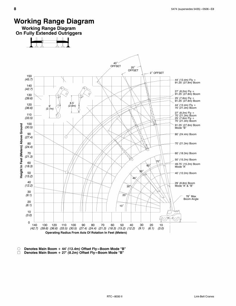
Working Range DiagramWorking Range Diagram
On Fully Extended Outriggers
1020405060708090100 30110130 120140
Operating Radius From Axis Of Rotation In Feet (Meters)
HeightInFeet(Meters)AboveGround
(3.0)(6.1)(12.2)(15.2)(18.3)(21.3)(24.4)(27.4)(30.5) (9.1)(33.5)(39.6) (36.6)(42.7)
150(45.7)
140(42.7)
130(39.6)
120(36.6)
110(33.5)
100(30.5)
90(27.4)
80(24.4)
70(21.3)
60(18.3)
50(15.2)
40(12.2)
30(9.1)
20(6.1)
10(3.0)
0
44’ (13.4m) Fly +91.25’ (27.8m) Boom
27’ (8.2m) Fly +91.25’ (27.8m) Boom25’ (7.6m) Fly +91.25’ (27.8m) Boom
25’ (7.6m) Fly +70’ (21.3m) Boom91.25’ (27.8m) BoomMode “B”
80’ (24.4m) Boom
70’ (21.3m) Boom
60’ (18.3m) Boom
49.75’ (15.2m) BoomMode “A”
50’ (15.2m) Boom
29’ (8.8m) BoomMode “A” & “B”
78˚ MaxBoom Angle
f Denotes Main Boom + 44’ (13.4m) Offset Fly---Boom Mode “B”j Denotes Main Boom + 27’ (8.2m) Offset Fly---Boom Mode “B”
40’ (12.2m) Boom
20˚
30˚
40˚
50˚
60˚70˚
10˚
2˚ OFFSET
9’(2.7m)
8.5’(2.6m)
40˚OFFSET 20˚
OFFSET
44’ (13.4m) Fly +70’ (21.3m) Boom
27’ (8.2m) Fly +70’ (21.3m) Boom
95474 (supersedes 5435)---0506---E8
RTC---8030 IILink-Belt Cranes
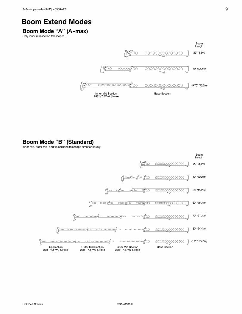
Boom Extend ModesBoom Mode “A” (A--max)
Boom Mode “B” (Standard)
Only inner mid section telescopes.
Inner mid, outer mid, and tip sections telescope simultaneously.
Base SectionTip Section288” (7.57m) Stroke
BoomLength
29’ (8.8m)
40’ (12.2m)
49.75’ (15.2m)
50’ (15.2m)
60’ (18.3m)
70’ (21.3m)
80’ (24.4m)
91.25’ (27.8m)
Outer Mid Section288” (7.57m) Stroke
Inner Mid Section288” (7.57m) Stroke
Base SectionInner Mid Section288” (7.57m) Stroke
BoomLength
29’ (8.8m)
40’ (12.2m)
10 5474 (supersedes 5435)---0506---E8
RTC---8030 II Link-Belt Cranes
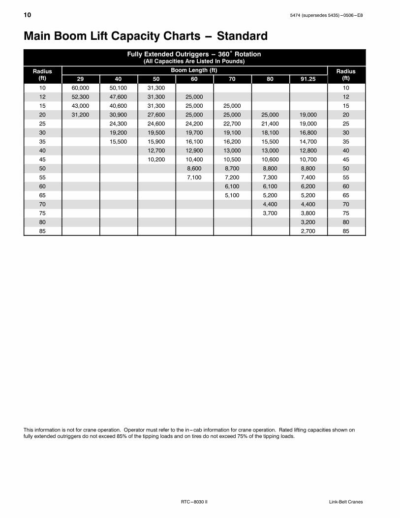
Main Boom Lift Capacity Charts -- StandardFully Extended Outriggers -- 360˚ Rotation
(All Capacities Are Listed In Pounds)
Radius(ft)
Boom Length (ft) Radius(ft)29 40 50 60 70 80 91.25
10 60,000 50,100 31,300 1012 52,300 47,600 31,300 25,000 1215 43,000 40,600 31,300 25,000 25,000 1520 31,200 30,900 27,600 25,000 25,000 25,000 19,000 2025 24,300 24,600 24,200 22,700 21,400 19,000 2530 19,200 19,500 19,700 19,100 18,100 16,800 3035 15,500 15,900 16,100 16,200 15,500 14,700 3540 12,700 12,900 13,000 13,000 12,800 4045 10,200 10,400 10,500 10,600 10,700 4550 8,600 8,700 8,800 8,800 5055 7,100 7,200 7,300 7,400 5560 6,100 6,100 6,200 6065 5,100 5,200 5,200 6570 4,400 4,400 7075 3,700 3,800 7580 3,200 8085 2,700 85
This information is not for crane operation. Operator must refer to the in---cab information for crane operation. Rated lifting capacities shown onfully extended outriggers do not exceed 85% of the tipping loads and on tires do not exceed 75% of the tipping loads.

115474 (supersedes 5435)---0506---E8
RTC---8030 IILink-Belt Cranes
On Tires -- Stationary -- Boom Centered Over Front Between Tire Tracks(All Capacities Are Listed In Pounds)
Radius(ft)
Boom Length (ft) Radius(ft)29 40 50 60
10 32,800 25,000 1012 28,900 28,600 1215 24,300 24,800 1520 17,400 18,100 18,300 2025 12,300 12,600 12,700 2530 8,800 9,200 9,300 3035 6,500 6,900 7,100 3540 5,200 5,400 4045 4,000 4,200 4550 3,200 5055 2,500 55
On Tires -- Pick & Carry (Creep) -- Boom Centered Over Front(All Capacities Are Listed In Pounds)
Radius(ft)
Boom Length (ft) Radius(ft)29 40 50 60
10 31,900 25,000 1012 27,600 25,000 1215 22,700 23,200 1520 17,000 17,500 17,800 2025 12,300 12,600 12,700 2530 8,800 9,200 9,300 3035 6,500 6,900 7,100 3540 5,200 5,400 4045 4,000 4,200 4550 3,200 5055 2,500 55
On Tires -- Stationary -- 360˚ Rotation(All Capacities Are Listed In Pounds)
Radius(ft)
Boom Length (ft) Radius(ft)29 40 50 60
10 24,000 24,400 1012 17,700 18,200 1215 12,000 12,700 1520 7,000 7,700 7,900 2025 4,900 5,200 5,300 2530 3,100 3,400 3,600 3035 1,800 2,200 2,400 35
This information is not for crane operation. Operator must refer to the in---cab information for crane operation. Rated lifting capacities shown onfully extended outriggers do not exceed 85% of the tipping loads and on tires do not exceed 75% of the tipping loads.

12 5474 (supersedes 5435)---0506---E8
RTC---8030 II Link-Belt Cranes
Fly Attachment Lift Capacity Charts -- OptionalFully Extended Outriggers -- 360˚ Rotation
(All Capacities Are Listed In Pounds)91.25 ft Main Boom Length
Radius(ft) 25 ft Fixed Fly
30 10,20035 10,20040 9,80045 9,20050 8,40055 7,70060 6,90065 5,90070 5,10075 4,40080 3,80085 3,30090 2,90095 2,500100 2,100105 1,800110 1,500
This information is not for crane operation. Operator must refer to the in---cab information for crane operation. Rated lifting capacities shown onfully extended outriggers do not exceed 85% of the tipping loads and on tires do not exceed 75% of the tipping loads.

135474 (supersedes 5435)---0506---E8
RTC---8030 IILink-Belt Cranes
Fully Extended Outriggers -- 360˚ Rotation(All Capacities Are Listed In Pounds)
91.25 ft Main Boom Length2˚ Fly Offset
91.25 ft Main Boom Length20˚ Fly Offset
91.25 ft Main Boom Length40˚ Fly Offset
Radius(ft)
Fly Length (ft) Radius(ft)
Fly Length (ft) Radius(ft)
Fly Length (ft)27 44 27 44 27 44
30 9,900 35 7,200 45 5,00035 9,700 6,500 40 6,800 50 4,80040 9,300 6,000 45 6,400 55 4,60045 8,600 5,500 50 6,100 3,600 60 4,500 2,50050 7,800 5,100 55 5,800 3,400 65 4,400 2,40055 7,200 4,700 60 5,500 3,200 70 4,300 2,30060 6,600 4,400 65 5,200 3,100 75 4,200 2,30065 5,600 4,100 70 5,000 2,900 80 4,000 2,20070 4,800 3,800 75 4,400 2,800 85 3,400 2,20075 4,100 3,600 80 3,800 2,700 90 2,900 2,10080 3,500 3,400 85 3,200 2,500 95 2,400 2,10085 3,000 3,200 90 2,800 2,400 100 2,10090 2,600 2,800 95 2,300 2,400 105 2,10095 2,200 2,400 100 2,000 2,300 110 1,800100 1,800 2,000 105 1,600 2,000 115 1,500105 1,500 1,700 110 1,300 1,700110 1,400 115 1,400
This information is not for crane operation. Operator must refer to the in---cab information for crane operation. Rated lifting capacities shown onfully extended outriggers do not exceed 85% of the tipping loads and on tires do not exceed 75% of the tipping loads.
14 5474 (supersedes 5435)---0506---E8
RTC---8030 II Link-Belt Cranes
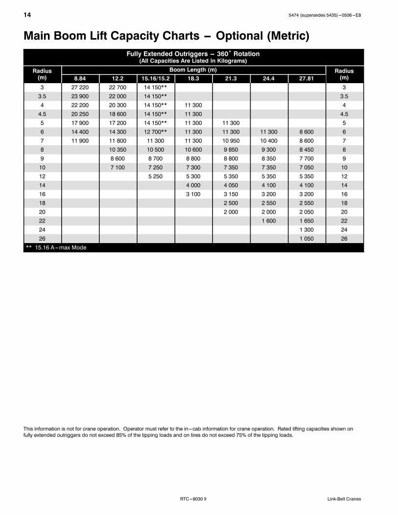
Main Boom Lift Capacity Charts -- Optional (Metric)Fully Extended Outriggers -- 360˚ Rotation
(All Capacities Are Listed In Kilograms)
Radius(m)
Boom Length (m) Radius(m)8.84 12.2 15.16/15.2 18.3 21.3 24.4 27.81
3 27 220 22 700 14 150** 33.5 23 900 22 000 14 150** 3.54 22 200 20 300 14 150** 11 300 44.5 20 250 18 600 14 150** 11 300 4.55 17 900 17 200 14 150** 11 300 11 300 56 14 400 14 300 12 700** 11 300 11 300 11 300 8 600 67 11 900 11 800 11 300 11 300 10 950 10 400 8 600 78 10 350 10 500 10 600 9 850 9 300 8 450 89 8 600 8 700 8 800 8 800 8 350 7 700 910 7 100 7 250 7 300 7 350 7 350 7 050 1012 5 250 5 300 5 350 5 350 5 350 1214 4 000 4 050 4 100 4 100 1416 3 100 3 150 3 200 3 200 1618 2 500 2 550 2 550 1820 2 000 2 000 2 050 2022 1 600 1 650 2224 1 300 2426 1 050 26
** 15.16 A---max Mode
This information is not for crane operation. Operator must refer to the in---cab information for crane operation. Rated lifting capacities shown onfully extended outriggers do not exceed 85% of the tipping loads and on tires do not exceed 75% of the tipping loads.

155474 (supersedes 5435)---0506---E8
RTC---8030 IILink-Belt Cranes
On Tires -- Stationary -- Boom Centered Over Front Between Tire Tracks(All Capacities Are Listed In Kilograms)
Radius(m)
Boom Length (m) Radius(m)8.84 12.2 15.2 18.3
3 15 050 11 300 33.5 13 500 11 300 3.54 12 250 12 100 44.5 11 150 11 300 4.55 9 800 10 000 56 7 050 7 300 7 400 67 5 300 5 600 5 700 5 750 78 4 450 4 550 4 600 89 3 600 3 700 3 750 910 2 900 3 050 3 100 1012 2 100 2 200 1214 1 550 1416 1 100 16
On Tires -- Pick & Carry (Creep) -- Boom Centered Over Front(All Capacities Are Listed In Kilograms)
Radius(m)
Boom Length (m) Radius(m)8.84 12.2 15.2 18.3
3 14 650 11 300 33.5 13 000 11 300 3.54 11 600 11 500 44.5 10 450 10 650 4.55 9 450 9 650 56 7 050 7 300 7 400 67 5 300 5 600 5 700 5 750 78 4 450 4 550 4 600 89 3 600 3 700 3 750 910 2 900 3 050 3 100 1012 2 100 2 200 1214 1 550 1416 1 100 16
This information is not for crane operation. Operator must refer to the in---cab information for crane operation. Rated lifting capacities shown onfully extended outriggers do not exceed 85% of the tipping loads and on tires do not exceed 75% of the tipping loads.

16 5474 (supersedes 5435)---0506---E8
RTC---8030 II Link-Belt Cranes
On Tires -- Stationary -- 360˚ Rotation(All Capacities Are Listed In Kilograms)
Radius(m)
Boom Length (m) Radius(m)8.84 12.2 15.2 18.3
3 9 650 9 850 33.5 7 450 7 650 3.54 5 950 6 200 44.5 4 850 5 100 4.55 4 050 4 300 56 2 850 3 100 3 200 67 2 050 2 300 2 400 2 450 78 1 700 1 800 1 900 89 1 250 1 400 1 450 910 900 1 050 1 100 10
Fly Attachment Lift Capacity Charts -- Optional (Metric)Fully Extended Outriggers -- 360˚ Rotation
(All Capacities Are Listed In Kilograms)27.81m Main Boom Length
Radius(m) 7.62m Fixed Fly
9 4 60010 4 60012 4 45014 4 10016 3 50018 2 80020 2 30022 1 90024 1 55026 1 30028 1 05030 90032 70034 600
This information is not for crane operation. Operator must refer to the in---cab information for crane operation. Rated lifting capacities shown onfully extended outriggers do not exceed 85% of the tipping loads and on tires do not exceed 75% of the tipping loads.

175474 (supersedes 5435)---0506---E8
RTC---8030 IILink-Belt Cranes
Fully Extended Outriggers -- 360˚ Rotation(All Capacities Are Listed In Kilograms)
27.81m Main Boom Length2˚ Fly Offset
27.81m Main Boom Length20˚ Fly Offset
27.81m Main Boom Length40˚ Fly Offset
Radius(m)
Fly Length (m) Radius(m)
Fly Length (m) Radius(m)
Fly Length (m)8.23 13.41 8.23 13.41 8.23 13.41
9 4 500 12 3 100 14 2 25010 4 500 14 2 850 16 2 15012 4 250 2 750 16 2 700 1 600 18 2 050 1 15014 3 850 2 500 18 2 500 1 500 20 2 000 1 10016 3 350 2 250 20 2 350 1 400 22 1 950 1 05018 2 700 2 000 22 1 950 1 300 24 1 650 1 00020 2 200 1 850 24 1 550 1 200 26 1 350 1 00022 1 800 1 700 26 1 300 1 150 28 1 100 95024 1 450 1 550 28 1 050 1 100 30 95026 1 200 1 300 30 800 1 000 32 85028 950 1 050 32 650 800 34 65030 750 850 34 60032 600 70034 550
This information is not for crane operation. Operator must refer to the in---cab information for crane operation. Rated lifting capacities shown onfully extended outriggers do not exceed 85% of the tipping loads and on tires do not exceed 75% of the tipping loads.

18 5474 (supersedes 5435)---0506---E8
RTC---8030 II Link-Belt Cranes
This Page Intentionally Blank

195474 (supersedes 5435)---0506---E8
RTC---8030 IILink-Belt Cranes

5474 (supersedes 5435)---0506---E8
RTC---8030 II Link-Belt Cranes
Link--Belt Construction Equipment Company Lexington, Kentucky www.linkbelt.comRLink--Belt is a registered trademark. Copyright 2006. We are constantly improving our products and therefore reserve the right to change designs and specifications.
Litho in U.S.A. 10/99 #6244
�������������� Hydraulic Rough Terrain Crane
RTC–8030 Series II 30–ton (27.2 metric tons)
Four–Section Boom Capacities
Boom and Fly Capacities for this machine are listed by the following sections.
Fully Extended Outriggers� Working Range Diagram� 29’ to 49’ 9” Main Boom Capacities, “A–max” Mode� 29’ to 91’ 3” Main Boom Capacities, Basic Mode “B”� 25’ Fly Capacities, Basic Mode “B”� 27’ to 44’ Fly Capacities, Basic Mode “B”
On Tires� Working Range Diagram� 29’ to 49’ 9” Main Boom Capaicities, “A–max” Mode� 29’ to 60’ Main Boom Capacities, Basic Mode “B”
RTC–8030
Link–Belt
CAUTION: This material is supplied for reference use only. Operator must refer toin–cab Crane Rating Manual to determine allowable machine lifting capacities andoperating procedures.

����RTC–8030 Series II
����������� ��� ��������� � � ���������� ��� ������ ������ ��� � �
��������� ����������� ��� ����� ������� ���������� ������ ������������������������� �� �������������� ������������������������
����������
OPERATING INSTRUCTIONS��������1. Rated lifting capacities in pounds as shown on lift charts
pertain to this crane as originally manufactured andnormally equipped. Modifications to the crane or use ofoptional equipment other than that specified can resultin a reduction of capacity.
2. Construction equipment can be dangerous if improperlyoperated or maintained. Operation and maintenance ofthis crane must be in compliance with the information inthe Operator’s, Parts, and Safety Manuals supplied withthis crane. If these manuals are missing, orderreplacements through the distributor.
3. The operator and other personnel associated with thiscrane shall read and fully understand the latestapplicable American National Standards ASME B30.5safety standards for cranes.
4. The rated lifting capacities are based on crane standinglevel on firm supporting surface.
�����1. The crane shall be leveled on a firm supporting surface.
Depending on the nature of the supporting surface, itmay be necessary to have structural supports under theoutrigger pontoons or tires to spread the load to a largerbearing surface.
2. When making lifts on outriggers, all tires must be free ofsupporting surface. All outrigger beams must beextended to the same length; fully retracted,intermediate extended, or fully extended.
3. When operating on tires over side, do not exceed 75�maximum boom angle. Loss of backward stability willoccur causing a backward tipping condition.
4. When making lifts on tires, they must be inflated to therecommended pressure. (See Operation note 20 andTire Inflation.)
5. For required parts of line, see Wire Rope Capacity andWinch Performance.
6. Before setting up on intermediate outriggers, retractedoutriggers, or tires, refer to Working Range Diagramsand rated lifting capacities to determine allowable craneconfigurations.
����������1. Rated lifting capacities at rated radii shall not be
exceeded. Do not tip the crane to determine allowableloads. For concrete bucket operation, weight of bucketand load shall not exceed 80% of rated lifting capacities.For clamshell bucket operation, weight of bucket andbucket contents is restricted to a maximum weight of5,000 pounds or 80% of rated lifting capacity, whicheveris less. For magnet operation, weight of magnet andload is restricted to a maximum weight of 5,000 poundsor 80% of rated lifting capacity, whichever is less. Forclamshell and magnet operation, maximum boomlength is restricted to 40 feet and the boom angle isrestricted to a minimum of 35�. Lifts with any fly erectedare prohibited for both clam and magnet operation.
2. Rated lifting capacities shown on fully extendedoutriggers do not exceed 85% of the tipping loads. Ratedlifting capacities shown on intermediate extended or fullyretracted outriggers are determined by the formula, ratedload = (tipping load – 0.1 X load factor) / 1.25. Rated liftingcapacities shown on tires do not exceed 75% of thetipping loads. Tipping loads are determined by SAE cranestability test code J–765.
3. Rated lifting capacities in the shaded areas are based onstructural strength or hydraulic limitations and have beentested to meet minimum requirements of SAE J–1063cantilevered boom crane structures–method of test.Rated lifting capacities in the non–shaded areas arebased on stability ratings. Some capacities are limited bya maximum obtainable 78� boom angle.
4. Rated lifting capacities include the weight of hookball/block, slings, bucket, magnet and auxiliary liftingdevices. Their weights must be subtracted from the listedrated capacity to obtain the net load that can be lifted.Rated lifting capacities include the deduct for any flystowed on the base of the boom. For deducts of any flyerected, but not used, see Capacity Deductions ForAuxiliary Load Handling Equipment.
5. Rated lifting capacities are based on freely suspendedloads. No attempt shall be made to move a loadhorizontally on the ground in any direction.
6. Rated lifting capacities are for lift crane service only.7. Do not operate at radii or boom lengths (minimum or
maximum) where capacities are not listed. At thesepositions, the crane can tip or cause boom failure.

���� RTC–8030 Series II
8. The maximum loads that can be telescoped are notdefinable because of variation in loadings and cranemaintenance, but it is permissible to attempt retractionand extension within the limits of the applicable load ratingchart.
9. For main boom capacities when either boom length orradius or both are between values listed, proceed asfollows:
a. For boom lengths not listed, use rating for next longer boom length or next shorter boom length,whichever is smaller.
b. For load radii not listed, use rating for next larger radius.
10. The user shall operate at reduced ratings to allow foradverse job conditions, such as: soft or uneven ground,out of level conditions, wind, side loads, pendulumaction, jerking or sudden stopping of loads, hazardousconditions, experience of personnel, traveling withloads, electrical wires, etc. Side load on boom or fly isdangerous and shall be avoided.
11. Rated lifting capacities do not account for wind onsuspended load or boom. Rated capacities and boomlength shall be appropriately reduced as wind velocityapproaches 20 mph.
12. When making lifts with auxiliary head machinery, theeffective length of the boom increases by 2 feet.
13. Power sections of boom must be extended inaccordance with boom mode “A” or “B”. In boom mode“B” all power sections must be extended or retractedequally.
14. The least stable rated working area depends on theconfiguration of the crane set up.
15. Rated lifting capacities are based on correct reeving.Deduction must be made for excessive reeving. Anyreeving over minimum required (see Wire RopeCapacity) is considered excessive and must beaccounted for when making lifts. Use Working RangeDiagram to estimate the extra feet of rope then deduct 1lb. for each extra foot of wire rope before attempting to lifta load.
16. The loaded boom angle combined with the boom lengthgive only an approximation of the operating radius. Theboom angle, before loading, should be greater toaccount for deflection. For main boom capacities, theloaded boom angle is for reference only. For flycapacities, the load radius is for reference only.
��� ���� ���� ������ � ����� ���� ����� ������� �� � ���
��������� ��� ������� ���� � � ���!� ���� ����� ��� � ��
����������������������������" ������������������������������������������� ����� �����" ��������#�������
��������������������������������������
�$� ������������� ������������������������ ������ ��������������� ������������������������������������
" ���� ���� � ���� ����� ��� ���� ������ ���� ���� � ���
����!�" ��������#���������������������������������������������
19. The 29ft. boom length structural capacities are based onboom fully retracted. If the boom is not fully retracted, donot exceed capacities shown for the 40ft. boom length.
20. Rated lifting capacities on tires depend on tire capacity,condition of tires, and tire air pressure. On tire capacitiesrequire lifting from main boom head only on a smoothand level surface. Pick and carry operations arerestricted to speed of 2.5 mph and creep. The boommust be centered over the front of the crane withtwo–position travel swing lock engaged and the loadmust be restrained from swinging. Lifts with any flyerected on tires are prohibited. For correct tire pressure,see Tire Inflation.
������������1. Load Radius: Horizontal distance from a projection of
the axis of rotation to the supporting surface, beforeloading, to the center of the vertical hoist line or tacklewith load applied.
2. Loaded Boom Angle: � ° The angle between the boombase section and horizontal with freely suspended loadat the rated radius.
3. Working Area: Area measured in a circular arc about thecenter line of rotation as shown on the Working AreaDiagram.
4. Freely Suspended Load: Load hanging free with nodirect external force applied except by the hoist line.
5. Side Load: Horizontal side force applied to the liftedload either on the ground or in the air.
6. No Load Stability Limit: The radius or boom anglebeyond which it is not permitted to position the boombecause the crane can overturn without any load on thehook.
7. Load Factor: Load applied at the boom tip which givesthe same moment effect as the boom mass.
8. Creep: Crane movement limited to 200 ft. in a 30 min.period and not to exceed 1 mph maximum speed.

��%�RTC–8030 Series II
TIRE INFLATION
Tire Size Operation Tire Pressure (psi)
2.5 mph 7620.5 X 25–24
Ply RatingCreep 95
Ply RatingStationary 95
2.5 mph 8320.5R25
1Star RatingCreep 83
1Star RatingStationary 87
PONTOON LOADINGS
Carga Máximaen el Flotador
Maximum Pontoon GroundBearing Pressure:
50,600 lb 208 psi
Boom Mode “A”
Boom Mode “B”
Only inner mid sectiontelescopes.
Inner–mid, outer–mid andtip sections telescope simultaneously.
��
%
�
&
�
$
�����
%
%����
Inner Mid Section 249” Stroke
Base SectionTip Section249”Stroke
Outer MidSection
249” Stroke
Inner MidSection
249” Stroke
��
Base Section
'��� ������ (���)
'��� ������ (���)
WINCH PERFORMANCEWinch Line Pulls Drum Rope Capacity
Two Speed WinchDrum Rope Capacity
(Ft.)
Wire Low Speed High SpeedWireRope Lay-
erAvailable
Lbs.*Available
Lbs.Layer Total
1 11,948 6,125 77 772 10,807 5,540 84 1613 9,866 5,058 93 2544 9,075 4,652 101 3555 8,401 4,307 109 464
* Maximum lifting capacity:Type DB Rope = 11,770 Type RB Rope = 9,080
WIRE ROPE CAPACITY
Maximum Lifting Capacities Based On Wire Rope Strength5/8” 5/8”Parts of
Line TypeDB
TypeRB
Notes
1 11,770 9,080 Capacities shown are in
2 23,540 18,160 pounds and working loadsmust not exceed the rat-
3 35,310 27,240must not exceed the rat-ings on the capacity charts
4 47,080 36,320in the Crane Rating Manu-al.
5 58,850 45,400al.Study Operator’s Manual
6 70,620 54,480Study Operator’s Manualfor wire rope inspection
7 82,390 63,560procedures and single partof line application.
LBCE DESCRIPTION
Type DB6 X 26 (6 X 19 Class) – Warrington Seale – ExtraImproved Plow Steel – Preformed – Right Regu-lar Lay – I.W.R.C.
Type RB 18 X 19 Rotation Resistant – Compacted Strand– High Strength, Preformed, Right Regular Lay
HYDRAULIC CIRCUIT PRESSURE SETTINGSFunction Pressure (psi)
Front And Rear Winch 3500Outrigger 3000Boom Hoist/ Telescope 3500Swing 1600Steering 2700Pilot Control 500Throttle 150

���� RTC–8030 Series II
WORKING AREAS
Note: These Lines Determine The Limiting Position Of AnyLoad For Operation Within Working Areas Indicated.
RTC On TiresBoom Centered
Over Front
Center OfRotation
C Front WheelTrack
L360�Chart
See Note
OverFront
C BoomL
Center OfRotation
LongitudinalC of RTCL
C BoomL
360�Chart
See Note
OverFront
OverSide
OverSide
RTC On Outriggers
See Note
See Note
OverRear
LongitudinalC of RTCL
C Outrigger PontoonL
CAPACITY DEDUCTIONS FOR AUXILIARYLOAD HANDLING EQUIPMENT
Load Handling Equipment Weight (lbs)
Auxiliary Head Attached 75
30 Ton Quick Reeve 3 Sheave Hook Block (SeeHook Block For Actual Weight) 720
8.5 Ton Hook Ball (See Hook Ball For Actual Weight) 360
Lifting From Main Boom With:
Fly Stowed On Boom Base(See Operation Note 4) 0
25 Ft. Fixed Fly Erected But Not Used 1300
27 Ft. Offset Fly Erected But Not Used 2300
44 Ft. Offset Fly Erected But Not Used 4300
Lifting From 27 Ft. Offset Fly With:
17 Ft. Fly Tip Erected But Not Used PROHIBITED
17 Ft. Fly Tip Stowed On 27 Ft. Offset Fly PROHIBITED
Note: Capacity deductions are forLink–Belt supplied equipment only.

��&�RTC–8030 Series II
WORKING RANGE DIAGRAMH
eig
ht
in f
eet
abo
ve g
rou
nd
������������������� ������!"!�#������"$ ��������%&��%'! !�(�)����"�"����!*�
��%��)������������"$��)�!+�"���))�*��%'! !�(�! �,,#��%#)!"$��!--!"$��"&!�!�"�
�������
Note: Boom and fly geometry shown are for unloaded condition and crane standing level on firm supportingsurface. Boom deflection, subsequent radius and boom angle change must be accounted for when applyingload to hook.
Operation radius from axis of rotation in feet
0
10
20
30
40
50
60
80
90
100
110
120
*+,-,.+/
70
130
140
20�
30�
40�
50�
60�70�
10�
15044 FT. FLY + 91.25 FT. BOOM
27 FT. FLY + 91.25 FT. BOOM25 FT. FLY + 91.25 FT. BOOM
27 FT. FLY + 70 FT. BOOM25 FT. FLY + 70 FT. BOOM
80 FT. BOOM
70 FT. BOOM
60 FT. BOOM
50 FT. BOOM49.75 FT. BOOM – MODE “A”
78� MAX.BOOM ANGLE
140 130 120 110 100 90 80 70 60 50 40 30 20 10
Fully Extended Outriggers
8.5’9’
40�OFFSET 20�
OFFSET 2�OFFSET
44 FT. FLY + 70 FT. BOOM
91.25 FT. BOOM – MODE “B”
40 FT. BOOM
29 FT. BOOM – MODES “A” & “B”
CL
5.5’5.5’
Denotes Main Boom + 44 Ft. Offset Fly – Boom Mode “B”� Denotes Main Boom + 27 Ft. Offset Fly – Boom Mode “B”

���� RTC–8030 Series II
FULL MAIN BOOM “A”
Rated Lifting Capacities InPoundsFully Extended OutriggersSee Set Up Note 2
Load 29 Ft. 40 Ft. 50 Ft.LoadRadius
(Ft.) � ° 360° OverFront � ° 360° Over
Front � ° 360° OverFront
10 64.5 60,000 60,000 72.5 50,100 50,100 76.0 31,300 31,300
12 60.0 52,300 52,300 69.5 47,600 47,600 74.0 31,300 31,300
15 52.5 43,000 43,000 64.5 40,600 40,600 70.5 31,300 31,300
20 37.0 31,200 31,200 56.0 30,900 30,900 64.0 27,600 27,600
25 46.0 23,300 23,300 57.0 22,900 22,900
30 34.5 18,300 18,300 49.5 18,100 18,100
35 14.5 14,600 14,600 41.0 14,500 14,500
40 30.5 11,200 11,200
45 11.5 8,700 8,800
Min.BmAng./Cap.
0(24.8) 22,400 22,400 0
(35.8) 14,100 14,100 0(45.5) 8,500 8,500
Note: Refer To Page 5 For “Capacity Deductions For Load Handling Equipment.” � ° Loaded Boom Angle In Degrees. ( ) Reference Radius For Minimum Boom AngleCapacities (Shown in Parenthesis) Are In Feet. *This Capacity Based On MaximumObtainable Boom Angle.
MAIN BOOM “B”FULL
Rated Lifting Capacities InPoundsFully Extended OutriggersSee Set Up Note 2
Load 29 Ft. 40 Ft. 50 Ft.LoadRadius
(Ft.) � ° 360° OverFront � ° 360° Over
Front � ° 360° OverFront
10 64.5 60,000 60,000 72.0 25,000 25,000 76.0 25,000 25,000
12 60.0 52,300 52,300 69.0 25,000 25,000 74.0 25,000 25,000
15 52.5 43,000 43,000 64.5 25,000 25,000 70.5 25,000 25,000
20 37.0 31,200 31,200 56.0 25,000 25,000 64.0 25,000 25,000
25 46.0 24,300 24,300 57.0 24,600 24,600
30 34.0 19,200 19,200 49.5 19,500 19,500
35 14.5 15,500 15,500 41.0 15,900 15,900
40 30.5 12,700 12,700
45 13.0 10,200 10,200
Min.Bm 0 0 0Ang./Cap.
0(24.8) 22,400 22,400 0
(35.8) 13,500 13,500 0(45.8) 9,500 9,500
Load 60 Ft. 70 Ft.LoadRadius
(Ft.) � ° 360° OverFront � ° 360° Over
Front12 76.5 25,000 25,000
15 74.5 25,000 25,000 77.0 25,000 25,000
20 69.0 25,000 25,000 73.0 25,000 25,000
25 64.0 24,200 24,200 68.5 22,700 22,700
30 58.0 19,700 19,700 64.0 19,100 19,100
35 52.0 16,100 16,100 59.0 16,200 16,200
40 45.5 12,900 12,900 54.0 13,000 13,000
45 37.5 10,400 10,500 48.5 10,500 10,600
50 28.0 8,600 8,600 42.0 8,700 8,700
55 12.0 7,100 7,100 35.0 7,200 7,300
60 26.0 6,100 6,100
65 11.5 5,100 5,100
Min.Bm. 0 0Min.Bm.Ang./Cap.
0(55.8) 6,900 6,900 0
(65.8) 4,900 5,000
Load 80 Ft. 91.25 Ft.LoadRadius
(Ft.) � ° 360° OverFront � ° 360° Over
Front20 76.0 25,000 25,000 78.0* 19,000 19,000
25 72.0 21,400 21,400 75.0 19,000 19,000
30 68.5 18,100 18,100 72.0 16,800 16,800
35 64.5 15,500 15,500 68.5 14,700 14,700
40 60.0 13,000 13,100 65.0 12,800 12,800
45 55.5 10,600 10,700 61.0 10,700 10,700
50 50.5 8,800 8,800 57.0 8,800 8,900
55 45.5 7,300 7,400 53.0 7,400 7,400
60 39.5 6,100 6,200 48.5 6,200 6,300
65 33.0 5,200 5,200 44.0 5,200 5,300
70 25.0 4,400 4,400 39.0 4,400 4,500
75 11.0 3,700 3,700 33.0 3,800 3,800
80 26.0 3,200 3,300
85 15.0 2,700 2,700
Min.Bm. 0 0Min.Bm.Ang./Cap.
0(75.8)
3,600 3,6000
(87.0)2,500 2,500
Note: Refer To Page 5 For “Capacity Deductions For Load Handling Equipment.” � ° Loaded Boom Angle In Degrees. ( ) Reference Radius For Minimum Boom AngleCapacities (Shown in Parenthesis) Are In Feet. *This Capacity Based On MaximumObtainable Boom Angle.

��$�RTC–8030 Series II
25 Ft. Fixed Fly
70 Ft. Main Boom
FULL
Rated Lifting Capacities In PoundsFully Extended OutriggersSee Set Up Note 2
� ° °Load Radius (Ft.) � ° 360°20 78.0* 15,20025 75.0 13,50030 72.0 12,20035 68.5 10,60040 65.5 9,80045 62.0 9,10050 58.5 8,20055 55.0 7,50060 51.0 7,00065 46.5 6,10070 42.0 5,30075 36.5 4,60080 30.5 4,00085 23.0 3,50090 10.5 3,000
Min.Bm.Min.Bm.Ang./Cap.
0 2,900
Note: Refer To Page 5 For “Capacity Deductions For Auxiliary Load Handling
Equipment”. �° Loaded Boom Angle In Degrees. * This Capacity Based On MaximumObtainable Boom Angle.
25 Ft. Fixed Fly
91.25 Ft. Main Boom
FULL
Rated Lifting Capacities In PoundsFully Extended OutriggersSee Set Up Note 2
� ° °Load Radius (Ft.) � ° 360°30 76.5 10,20035 74.5 10,20040 72.0 9,80045 69.5 9,20050 67.0 8,40055 64.0 7,70060 61.0 6,90065 58.0 5,90070 54.5 5,10075 51.0 4,40080 47.5 3,80085 43.5 3,30090 39.5 2,90095 35.0 2,500100 29.5 2,100105 23.5 1,800110 14.0 1,500
Min.Bm. Ang./Cap. 0 1,400
Note: Refer To Page 5 For “Capacity Deductions For Auxiliary Load Handling Equipment”. �° Loaded Boom Angle In Degrees.
27 Ft. Offset Fly
70 Ft. Main Boom
2� Offset
40� Offset
20�Offset
FULL
Rated Lifting Capacities In PoundsFully Extended OutriggersSee Set Up Note 2
Load 2� Offset 20� Offset 40� OffsetRadius
(Ft.) � ° 360° � ° 360° � ° 360°
25 75.5 13,00030 72.5 11,000 77.0 7,70035 69.0 10,100 73.5 7,100 78.0* 5,30040 66.0 9,300 70.5 6,500 74.5 5,00045 62.5 8,400 67.0 6,100 71.0 4,80050 59.5 7,600 63.5 5,700 67.5 4,60055 55.5 6,900 60.0 5,400 63.5 4,50060 52.0 6,400 56.5 5,100 59.5 4,40065 48.0 5,800 52.0 4,800 55.5 4,20070 43.5 5,000 48.0 4,600 50.5 4,20075 38.5 4,300 43.0 4,400 45.5 4,10080 32.5 3,700 37.0 3,90085 26.0 3,200 30.0 3,30090 16.5 2,800
Min. Bm.Ang./Cap. 0 2,400 0 2,500 0 2,700
Note: Refer To Page 5 For “Capacity Deductions For Auxiliary Load Handling
Equipment”. �° Loaded Boom Angle In Degrees. * This Capacity Based On MaximumObtainable Boom Angle.
44 Ft. Offset Fly
70 Ft. Main Boom
2� Offset
40� Offset
20�Offset
FULL
Rated Lifting Capacities In PoundsFully Extended OutriggersSee Set Up Note 2
Load 2� Offset 20� Offset 40� OffsetRadius
(Ft.) � ° 360° � ° 360° � ° 360°
30 76.0 7,40035 73.5 6,60040 70.5 5,800 77.0 4,00045 68.0 5,300 74.5 3,70050 65.0 4,800 71.5 3,500 78.0* 2,70055 62.5 4,300 69.0 3,200 75.0 2,50060 59.5 4,000 66.0 3,000 72.0 2,40065 56.5 3,700 63.0 2,900 68.5 2,30070 53.5 3,400 59.5 2,700 65.5 2,30075 50.0 3,100 56.5 2,600 61.5 2,20080 46.5 2,900 52.5 2,400 57.5 2,10085 42.5 2,700 49.0 2,300 53.5 2,10090 38.5 2,600 44.5 2,200 48.5 2,10095 34.0 2,400 40.0 2,200 43.0 2,100100 28.5 2,300 34.0 2,100105 21.0 2,000 26.0 2,100
Min.Bm.Min.Bm.Ang./Cap.
0 1,500 0 1,600 0 1,800
Note: Refer To Page 5 For “Capacity Deductions For Auxiliary Load Handling
Equipment”. �° Loaded Boom Angle In Degrees. * This Capacity Based On MaximumObtainable Boom Angle.
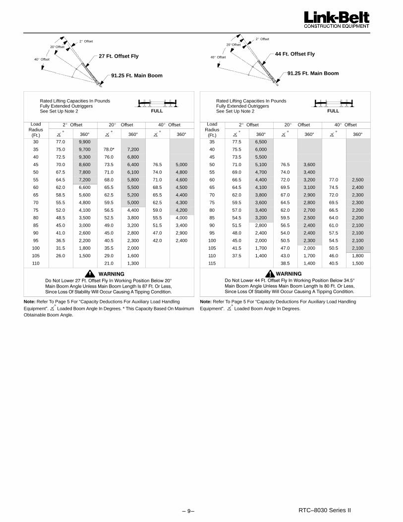
���� RTC–8030 Series II
27 Ft. Offset Fly
91.25 Ft. Main Boom
2� Offset
40� Offset
20�Offset
FULL
Rated Lifting Capacities In PoundsFully Extended OutriggersSee Set Up Note 2
Load 2� Offset 20� Offset 40� OffsetRadius
(Ft.) � ° 360° � ° 360° � ° 360°30 77.0 9,900
35 75.0 9,700 78.0* 7,200
40 72.5 9,300 76.0 6,800
45 70.0 8,600 73.5 6,400 76.5 5,000
50 67.5 7,800 71.0 6,100 74.0 4,800
55 64.5 7,200 68.0 5,800 71.0 4,600
60 62.0 6,600 65.5 5,500 68.5 4,500
65 58.5 5,600 62.5 5,200 65.5 4,400
70 55.5 4,800 59.5 5,000 62.5 4,300
75 52.0 4,100 56.5 4,400 59.0 4,200
80 48.5 3,500 52.5 3,800 55.5 4,000
85 45.0 3,000 49.0 3,200 51.5 3,400
90 41.0 2,600 45.0 2,800 47.0 2,900
95 36.5 2,200 40.5 2,300 42.0 2,400
100 31.5 1,800 35.5 2,000
105 26.0 1,500 29.0 1,600
110 21.0 1,300
0��/����������������+�� �������.��1��2����3� ������'������ °4���'����-�����5��� �4���'�����������. �$������+���� !
6������� �+��6��������1����+��"���" ����-�,���������������
�������
Note: Refer To Page 5 For “Capacity Deductions For Auxiliary Load Handling
Equipment”. �° Loaded Boom Angle In Degrees. * This Capacity Based On MaximumObtainable Boom Angle.
44 Ft. Offset Fly
91.25 Ft. Main Boom
2� Offset
40� Offset
20�Offset
FULL
Rated Lifting Capacities In PoundsFully Extended OutriggersSee Set Up Note 2
Load 2� Offset 20� Offset 40� OffsetRadius
(Ft.) � ° 360° � ° 360° � ° 360°35 77.5 6,500
40 75.5 6,000
45 73.5 5,500
50 71.0 5,100 76.5 3,600
55 69.0 4,700 74.0 3,400
60 66.5 4,400 72.0 3,200 77.0 2,500
65 64.5 4,100 69.5 3,100 74.5 2,400
70 62.0 3,800 67.0 2,900 72.0 2,300
75 59.5 3,600 64.5 2,800 69.5 2,300
80 57.0 3,400 62.0 2,700 66.5 2,200
85 54.5 3,200 59.5 2,500 64.0 2,200
90 51.5 2,800 56.5 2,400 61.0 2,100
95 48.0 2,400 54.0 2,400 57.5 2,100
100 45.0 2,000 50.5 2,300 54.5 2,100
105 41.5 1,700 47.0 2,000 50.5 2,100
110 37.5 1,400 43.0 1,700 46.0 1,800
115 38.5 1,400 40.5 1,500
0��/���������%%�����+�� �������.��1��2����3� ������'������%��°4���'����-�����5��� �4���'�����������. �$ �����+���� !
6������� �+��6��������1����+��"���" ����-�,���������������
�������
Note: Refer To Page 5 For “Capacity Deductions For Auxiliary Load Handling
Equipment”. �° Loaded Boom Angle In Degrees.

��� �RTC–8030 Series II
WORKING RANGE DIAGRAM
°
°
°
Denotes Main Boom 360° – Boom Mode “A”Denotes Main Boom 360° – Boom Mode “B”Denotes Main Boom Between Tire Tracks Or Centered Over Front – Boom Mode “A”Denotes Main Boom Between Tire Tracks Or Centered Over Front – Boom Mode “B”
Note: Boom geometry shown is for unloaded condition and crane standing level on firm supportingsurface. Boom deflection, subsequent radius and boom angle change must be accounted for whenapplying load to hook.
������������������� ������!"!�#������"$ ��������%&��%'! !�(�)����"�"���
�!*���%��)������������"$��)�!+�"���))�*��%'! !�(�! �,,#��%#)!"$��!--!"$��"&!�!�"�
ON TIRES
20304050
*+,-,.+/
29 FT. BOOM
607080
78� MAXIMUMBOOM ANGLE
�-��%�!�"�%&!#)*���%.!)�*���%�!�"!"*���
�
!$�
�!"
*�
��
%'
�+�
$��
#"
&
80
70
60
50
30
20
10
40
49.75 FT. BOOMMODE “A”
40 FT. BOOM
10
20
30
40
50
60
70
Crane Configurations Prohibited: Boom Lengths Greater than 60 FT. 25 Ft. Fixed Fly 27 Ft. Offset Fly 44 Ft. Offset Fly
�������
°
°
°
°
010
CL
50 FT. BOOM
MODES “A” & “B”
5.5’8.5’
5.5’
9’
MODE “B”60 FT. BOOM –
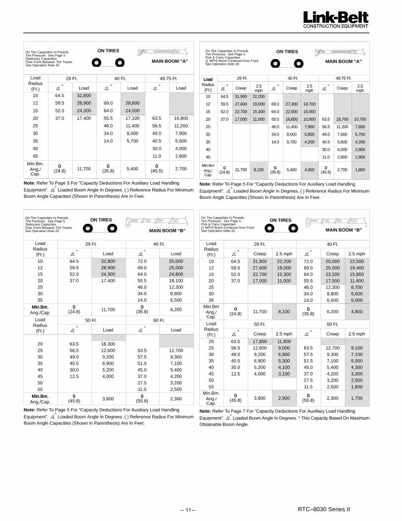
����� RTC–8030 Series II
MAIN BOOM “A”
ON TIRESOn Tire Capacities In PoundsTire Pressure: See Page 5Stationary CapacitiesOver Front Between Tire TracksSee Operation Note 20
Load 29 Ft. 40 Ft. 49.75 Ft.Radius
(Ft.) � ° Load � ° Load � ° Load
10 64.5 32,800
12 59.5 28,900 69.0 28,600
15 52.0 24,300 64.0 24,000
20 37.0 17,400 55.5 17,100 63.5 16,800
25 46.0 11,400 56.5 11,200
30 34.0 8,000 49.0 7,900
35 14.0 5,700 40.5 5,600
40 30.0 4,000
45 11.0 2,800
Min.Bm. 0 0 0Ang./Cap.
0(24.8) 11,700 0
(35.8) 5,400 0(45.5) 2,700
Note: Refer To Page 5 For “Capacity Deductions For Auxiliary Load Handling
Equipment”. �° Loaded Boom Angle In Degrees. ( ) Reference Radius For MinimumBoom Angle Capacities (Shown In Parenthesis) Are In Feet.
MAIN BOOM “B”
On Tire Capacities In PoundsTire Pressure: See Page 5Stationary CapacitiesOver Front Between Tire TracksSee Operation Note 20
ON TIRES
Load 29 Ft. 40 Ft.Radius
(Ft.) � ° Load � ° Load
10 64.5 32,800 72.0 25,00012 59.5 28,900 69.0 25,00015 52.0 24,300 64.0 24,80020 37.0 17,400 55.5 18,10025 46.0 12,30030 34.0 8,80035 14.0 6,500
Min.Bm. 0 0Min.Bm.Ang./Cap.
0(24.8) 11,700 0
(35.8) 6,200
Load 50 Ft. 60 Ft.Radius
(Ft.) � ° Load � ° Load
20 63.5 18,30025 56.5 12,600 63.5 12,70030 49.0 9,200 57.5 9,30035 40.5 6,900 51.5 7,10040 30.0 5,200 45.0 5,40045 12.5 4,000 37.0 4,20050 27.5 3,20055 11.5 2,500
Min.Bm. 0 0Min.Bm.Ang./Cap.
0(45.8) 3,800 0
(55.8) 2,300
Note: Refer To Page 5 For “Capacity Deductions For Auxiliary Load Handling
Equipment”. �° Loaded Boom Angle In Degrees. ( ) Reference Radius For MinimumBoom Angle Capacities (Shown In Parenthesis) Are In Feet.
On Tire Capacities In PoundsTire Pressure: See Page 5Pick & Carry Capacities(1 MPH) Boom Centered Over FrontSee Operation Note 20
MAIN BOOM “A”
ON TIRES
Load 29 Ft. 40 Ft. 49.75 Ft.LoadRadius
(Ft.) � ° Creep 2.5mph � ° Creep 2.5
mph � ° Creep 2.5mph
10 64.5 31,900 22,200
12 59.5 27,600 19,000 69.0 27,300 18,700
15 52.0 22,700 15,300 64.0 22,500 15,000
20 37.0 17,000 11,000 55.5 16,800 10,800 63.5 16,700 10,700
25 46.0 11,400 7,900 56.5 11,200 7,800
30 34.0 8,000 5,800 49.0 7,900 5,700
35 14.0 5,700 4,200 40.5 5,600 4,200
40 30.0 4,000 2,900
45 11.0 2,800 1,900
Min.Bm0 0 0
Ang./Cap
0(24.8) 11,700 8,100 0
(35.8) 5,400 4,000 0(45.5) 2,700 1,800
Note: Refer To Page 5 For “Capacity Deductions For Auxiliary Load Handling
Equipment”. �° Loaded Boom Angle In Degrees. ( ) Reference Radius For MinimumBoom Angle Capacities (Shown In Parenthesis) Are In Feet.
On Tire Capacities In PoundsTire Pressure: See Page 5Pick & Carry Capacities(1 MPH) Boom Centered Over Front See Operation Note 20 MAIN BOOM “B”
ON TIRES
Load 29 Ft. 40 Ft.Radius
(Ft.) � ° Creep 2.5 mph � ° Creep 2.5 mph
10 64.5 31,900 22,200 72.0 25,000 22,50012 59.5 27,600 19,000 69.0 25,000 19,40015 52.0 22,700 15,300 64.0 23,200 15,80020 37.0 17,000 11,000 55.5 17,500 11,60025 46.0 12,300 8,70030 34.0 8,800 6,60035 14.0 6,500 5,000
Min.Bm 0 0Ang./Cap.
0(24.8) 11,700 8,100 0
(35.8) 6,200 4,800
Load 50 Ft. 60 Ft.Radius
(Ft.) � ° Creep 2.5 mph � ° Creep 2.5 mph
20 63.5 17,800 11,80025 56.5 12,600 9,000 63.5 12,700 9,10030 49.0 9,200 6,900 57.5 9,300 7,10035 40.5 6,900 5,300 51.5 7,100 5,50040 30.0 5,200 4,100 45.0 5,400 4,30045 12.5 4,000 3,100 37.0 4,200 3,30050 27.5 3,200 2,50055 11.5 2,500 1,800
Min.Bm. 0 0Ang./Cap.
0(45.8) 3,800 2,900 0
(55.8) 2,300 1,700
Note: Refer To Page 7 For “Capacity Deductions For Auxiliary Load Handling
Equipment”. �° Loaded Boom Angle In Degrees. * This Capacity Based On MaximumObtainable Boom Angle.

�����RTC–8030 Series II
On Tire Capacities In PoundsTire Pressure: See Page 5Stationary Capacities – 360 DegreeSee Operation Note 20 MAIN BOOM “A”
360�
ON TIRES
Load 29 Ft. 40 Ft. 49.75 Ft.Radius
(Ft.) � ° Load � ° Load � ° Load
10 64.5 24,000
12 59.5 17,700 69.0 17,200
15 52.0 12,000 64.0 11,700
20 37.0 7,000 55.5 6,800 63.0 6,700
25 46.0 4,100 56.5 4,000
30 34.0 2,300 49.0 2,200
Min.Bm 0 26.5 45.5Ang./Cap.
0(24.8) 4,200 26.5
(32.3) ––– 45.5(31.9) –––
Note: Refer To Page 5 For “Capacity Deductions For Auxiliary Load Handling
Equipment”. �° Loaded Boom Angle In Degrees. ( ) Reference Radius For MinimumBoom Angle Capacities (Shown In Parenthesis) Are In Feet.
MAIN BOOM “B”
On Tire Capacities In PoundsTire Pressure: See Page 5Stationary Capacities–360 DegreeSee Operation Note 20
360�
ON TIRES
Load 29 Ft. 40 Ft.Radius
(Ft.) � ° Load � ° Load
10 64.0 24,000 72.0 24,400
12 59.5 17,700 69.0 18,200
15 52.0 12,000 64.0 12,700
20 37.0 7,000 55.5 7,700
25 45.5 4,900
30 34.0 3,100
35 14.0 1,800
Min.Bm. 0 0Min.Bm.Ang./Cap.
0(24.8) 4,200 0
(35.8) 1,700
Load 50 Ft. 60 Ft.Radius
(Ft.) � ° Load � ° Load
20 63.5 7,900
25 56.5 5,200 63.0 5,300
30 49.0 3,400 57.0 3,600
35 40.5 2,200 51.0 2,400
Min.Bm. 34 45.5Ang./Cap. (38.2) –––– (39.4) ––––
Note: Refer To Page 5 For “Capacity Deductions For Auxiliary Load Handling
Equipment”. �° Loaded Boom Angle In Degrees. ( ) Reference Radius For MinimumBoom Angle Capacities (Shown In Parenthesis) Are In Feet.
Link–Belt Construction Equipment Company Lexington, Kentucky linkbelt.com� Link–Belt is a registered trademark. Copyright 1999. All rights reserved. We are constantly improving our products and therefore reserve the right to change designs and specifications.

Litho in U.S.A. 2/02 #6301 (supersedes #6252)
Lifting CapacitiesTelescopic Rough Terrain Crane
RTC–8030 Series II 30–ton (27.2 metric ton)
Three–Section Boom Capacities
Boom and fly capacities for this machine are listed by the following sections:
Fully Extended Outriggers� Working Range Diagram� 30 to 78 ft. Main Boom capacities� 25 ft. offset fly capacities� 27 ft. offset fly capacities� 27 to 44 ft. two–piece offset fly capacities
On–Tires� Working Range Diagram� 30 to 78 ft. Main Boom capacities
RTC–8030
CAUTION: This material is supplied for reference use only. Operator must refer toin–cab Crane Rating Manual to determine allowable machine lifting capacities andoperating procedures.

���������������� ����� ��������� �������
������������������������ ������������������������������ ����������
����������� ��� ����� ������� ���������� ������ ��������� � � ������
��������� � �� ���� ��� ������ � ��� ����������� ��� ����� �� ��
���������
OPERATING INSTRUCTIONS
���������� ������� �� �������� � ��� ��������������� ������ ���������
����� �� ��� �� �� ������ ��� �� � ����!� ������������� ����������!��"� �������#�� � ��� ����������������������������� ������"� �������������������������� � �������������� ��������� ����������� �!�
�� ��������� ����"� ����������$������������ �� ��������!�������������� ��� �����%����� ��������� ������������� �������������$�� ������� ����� ������� ������� ��� �
����%�������&�'�(����'���������!�#������������ ��� ���� �� ������� � ��� ������ �������� ���� � �� ��'� ������������������������������� ��� $�����
� �������������������������������������� ����� ����� ������� ������ ����� ���� ����!� ����������� ���� ���������� ��$��� )��� ����*�� ����� ��������� )#+����,�����!����������������������
-� ����������� �� �������� � �������$������������������� ��
��.������� ���������� �����������
������� ����������������$����.����������� ���������� �����������
/����� ������������������������������� ����������'� ����!$�� ��������!� ��� ��.�� ����������� ��������� � ������ ������� ������������������ ����������������������������������$��� �����������
�� 0������1 ���� ����������� �����'������ ���������$���������������� ��� ��������� � )��� ���� ����� $����� ����� $��2�������������������������3�����!����������'� ������� ����2������'��������!��2�������
� 0���������� ������� �����.�������� ��'���������2�����4,���2 ����$����������� 5�������$��1 �������$ � �!� ������������ �����$��1 ����� �� ������� � ���
-� 0������1 ���� �������� ���'����!������$�� ��������������
���������������������� � 6���%����� ��������������� ��������� ���7
,� 8�����"� �������������� ��'�����0 ������������� �!����0 ����(�����������
9� ����������� ��������� ������� �������� �����'�������������� �����'����� ���'����������0��1 ���������/ ���������������� � �� ��� ����� � ��� ��� ������ ��� ���� �$��� �����
���� ����� ����
������������ ������ � �� ��� ����� � ��� ��� ������ ��� � ������ ���� $�
�2���������/������� ��������������������� ������� �$����������8������������$��1��������� ��'� � �������$��1����������������������2�������:����������� �� �������� � ���8��� ���������� $��1��� ������ ��'� � ���� ��� $��1��� ���$��1��� ��������� �� ����� ����� ��� ����2 ���� � ���� ��,����������������:����������� �� �������� �!'� � ���.��� �
�������8���������������� ��'� � ����������������������� ������ ������������2 ���� � �������,����������������:��������� � �� �������� �!'� � ���.��� �� ������ �8���������������� ������� ������ ��'� ��2 ���� $���� ������� ������ ��������-���������������$���������� ������� ���������� � �������,�����������5 ���� �����!���!����������������� $ ��������$�������������������������� ���
�� ������� �� �������� � ������ ���������!��2����������� �����
��������2������,:���� ���� � �� ��� ������� ������� � �� ������� � ��� ��� �� ��� ������� ���� �2������� ��� ����!�������������� ���������������� ����$!������������'�����������;�6� �� ������d – 0.��<������������7�=����,���������� �� ������� � ������ ������ �������������2������4,:��������� �� ���������� �� ������������������� ����$!�)+����������$ � �!����������J–79,�
� ������� �� �������� � ��� �����������������������$�������
������������������������!����� ��� � ��� ����������.��$���������� ��������� � ������"� �����������)+�>–��9���� ��.����� $���� ������ ������������������ ��� ����������� � �� ��� ����� � ��� �� ���� ����������� ������ ���$�����������$ � �!���� ��������������� � �������� � ����$!����2 �����$�� ��$���4���$����������
-� ������ � �� ��� ����� � ��� ������� ���� � ���� ��� � ���1
$���=$���1'� �� ���'� $��1��'� ������� ���� ��2 � ��!� � �� ����. ��������� �� � ����������$����$������������������ ��������������� �!�����$�� �������������������������$��� ����������� � �� ��� ����� � ��� ������� ���� ������� ���� ��!� ��!��� ����������$�����������$������8����������������!����!�������'� $��� ���� ����'� ���� ����� �!� /����� ���� 8��)�2 � ��!�5����?���� ���+"� ������
,� ������� �� �������� � �������$�������������!����������
������� � *�� �������� ������ $�� ����� ��� ��.�� �� ������� @������!��������������� ����!�� ���� ���
9� ������� �� �������� � ������������ ������������. ������!�4� /����������������� ��� ����$���� �������� 6� � ������
��2 ���7� ����� ����� � ��� ���� ���� � ������ � )�� �������� � ���'���������������� �����������$������ �����
�� ���� ��2 ���� ������ ����� ���� $�� ����������� ���� ������ ��$��� $������� ��� .�� �� ��� �� ���� ���� ���� �����
�� ��������'�$��� �� ������ �� $��������������������� �������2���� ��� �� ������� � �������������� ��$����������� ��������

– 3 –��������� ������� ������������ �����
A� 8����� ��$��������� � ��� ����� �����$���������������� ��� ��� $���� ���� $�� ���� .������ � ����'� �������� ������� �B�� 8���$����������������� ����'�������� ���������2��������
$����������������2����������$����������'� � ���.�� ����������
$� 8����������� ������ ����'�������� ���������2�����������C� ���
��� ��������� ������ ����������� �������� ��� ���� ������� � �����.�����D�$����� � ���'��������B������������.���������'
���� ��� ��.��� ���� � ���'� ��'� � ��� �����'� ����������� ��'�D��1 ������������������ �����������'���@���������� � ���'��2��� �����������������'����.�� ��� ��������'������ ���� ���'� ����� � ��� ����� ��� $���� ��� ��!� ���������������������$���.� ����
��� ������ � �� ��� ����� � ��� ��� ���� �������� ���� ��� ��������������������$����������������� � �������$����������������$��������� ����!������������ ���.���� �!
��������������������� 0���� ��1 ��� � ���� ��� ��2 � ��!� ����� ���� ���!'� ���
������ .����������������$���� ���������$!�������� (� ��� ���� ���� ��� $���� ����� $�� �2������� �"����!�
6���1�� ��� ������� ���� � �� ���� ���� �� �-� ���� ���� �������� ��7�
�-� ���� ������ ���$��� ������ ��1 ��� ����� �������� ��� ������� ����� �����������������������
�,� ������ � �� ��� ����� � ��� ���� $����� ��� �������� ���. ���/����� �������� $������� ���� �2���� .�� ���. ���� � )�!���. ��� �.��� � � ���� ��"� ���� 6���� 0 ��� ��������� �!7� �� ���� ������ �2���� .�� ���� ����� $��������������� ������1 ���� ����� �E���0��1 ��������/ ������������ ����������2�������������������������������$������������2������������ ��������$������������� ������� ���������
�9� �����������$�������������$ ���� �������$����������� .�����!���������2 ��� ���������������� ������ ��������$���� �����'� $������ ���� ��'� ������� $�� �������� ��������������������� �����8����� ��$��������� � ��'����������� $���� ������ �� ���� ���������� ���!�� � 8��� ��!����� � ��'������������� ��� �������������������!�
�4� 8�����!������ � ��� ����� ��$���������������������4�����'
��������������� � ������������� ����$!�����$����������� �������4������$����������!���������8����������������� �����������2�� �� ���$������������������� ����������������� �!�
��� ���������$��������������������������� � �������$�������$��������!��������������������$���� ����������!����������'��������2���������� � ������ ����������-������$�����������
�A� ������� �� �������� � ������� ��������������� �������� �!'���� � ������� ���'������ ���� �������������%��� �������� � ��
��"� ���� �� ���������� ��$������������!������������������.������������( �1���������!������� ������������� ������� ������ ��� ��,� ���� ���� ������� ���� $��������� $�����������.�������������������������� ���� ����� � �����.��� � ��� ���1� �������� ���� ���� ����� ����� $������� ���������� �� ����5 ���� �����!���!������������� ����������� $ �����8������������ �����������'������ ��������� ���
�������������� 5������� ��B��?�� @������� �����������������D��� ���������
�2 ���������� ����������������� ����������'�$���������� ��'���������������������.��� ������ ���� ���������1��� ����������� ���
�� 5�����������)����B�� ° ����������$�� ��������$���$�������� ���������� @������ ��������!������������������������������� ���
� 0��1 ���)���B��)������������� ����� ������������$�������������� � ��� ��� ����� ��� ��� ��� ����� ����0��1 ���)���/ ������
-� 8����!� ��������� 5���B� � 5���� ���� ��� ����� ��� ��� ������2����������������� ����2�����$!������� ���� ���
,� ���5���B��?�� @������� ������������� ����������� ���������� ���������������������� ������� ��
9� *�� 5���� ��$ � �!� 5 � �B� � ���� ��� ��� ��� $���� �����$�!����� � ��� �� ���������� ����������� � �������$���$����������������������.������� ��������!���������������1�
4� 5����8�����B��5�������� ����������$����� �� � ���� .��������������������������������$���������
�� �����B����������.������� � ��������������� ������� ������� ���������������2�������������2 ����������

��-������������� ����� ��������� �������
TIRE INFLATIONTire Size Operation Tire Pressure (psi)
Stationary 9520.5 X 25–24 Ply Rating Creep
2.5 mph9576
Stationary 8720.5R25 – 1 Star Radial Creep
2.5 mph8383
PONTOON LOADINGS
Maximum Pontoon Load:Maximum Pontoon
Ground Bearing Pressure:
50,600 lbs. 208 psi
CAPACITY DEDUCTIONS FOR AUXILIARY LOAD HANDLING EQUIPMENT
Load Handling Equipment: (lbs.)Auxiliary Head Attached 75
30–ton quick reeve 3 sheave hook block (see hook block for actual weight) 720
8.5–ton hook ball (see hook ball for actual weight) 360
Lifting From Main Boom With: (lbs.)
Fly Stowed On Boom Base (See Operation Note 4) 0
25 Ft. Fixed Fly Erected But Not Used 1300
27 Ft. Offset Fly Erected But Not Used 3,300
44 Ft. Offset Fly Erected But Not Used 6,600
Lifting From 28.5 ft. Offset Fly With:17 ft. fly tip erected but not used PROHIBITED
17 ft. fly tip stowed on 28.5 ft. offset fly PROHIBITED
Note: Capacity deductions are for Link–Belt supplied equipment only.
WINCH PERFORMANCEWinch Line Pulls
Two Speed WinchDrum Rope Capacity (ft.)
WireRope Low Speed High SpeedRopeLayer Available Lbs.* Available lbs.
Layer Total
1 11,948 6,125 77 77
2 10,807 5,540 85 161
3 9,866 5,058 93 254
4 9,075 4,652 101 355
5 8,401 4,307 109 464
*Maximum lifting capacity: Type DB Rope = 11,770 Type RB Rope = 9,080
WIRE ROPE CAPACITYMaximum Lifting Capacities Based On Wire Rope Strength
5/8” 5/8”Parts of Line
Type DB Type RBNotes
1 11,770 9,080
2 23,540 18,160 Capacities shown are in pounds
3 35,310 27,240
Capacities shown are in poundsand working loads must not ex-
4 47,080 36,320ceed the ratings on the capacitycharts in the Crane Rating Manual.
5 58,850 45,400
6 70,620 54,480Study Operator’s Manual for wirerope inspection procedures.
7 82,390 63,540
rope inspection procedures.
LBCE DESCRIPTION
TYPE DB
TYPE RB
6 x 26 (6 x 19 Class) – Warrington Seale – Extra ImprovedPlow Steel – Preformed – Right Regular Lay – I.W.R.C.
18 x 19 Rotation Resistant – Compacted Strand – HighStrength – Preformed – Right Regular Lay
HYDRAULIC CIRCUIT PRESSURE SETTINGSFunction Pressure (PSI)
Front And Rear Winch 3500Outriggers 3000Boom Hoist / Telescope 3500Swing 1600Steering 2700Pilot Control 500Throttle 150
WORKING AREAS
Note: These Lines Determine The Limiting Position Of Any Load For Operation Within Working Areas Indicated.
RTC On Tires
Boom Centered Over Front
Center Of Rotation
C Front Wheel TrackL360�Chart
See Note
OverFront
C BoomL
Center Of Rotation
LongitudinalC of RTCL
C BoomL
360�Chart See Note
OverFront
OverSide
RTC On Outriggers
See Note
See Note
OverRear
LongitudinalC of RTCL
C Outrigger PontoonL
OverSide

– 5 –��������� ������� ������������ �����
WORKING RANGE DIAGRAMH
eig
ht
in f
eet
abo
ve g
rou
nd
������������������� ������!"!�#������"$ ��������%&��%'! !�(�)����"�"����!*�
��%��)������������"$��)�!+�"���))�*��%'! !�(�! �,,#��%#)!"$��!--!"$��"&!�!�"�
�������
Note: Boom and fly geometry shown are for unloaded condition and crane standing level on firm supportingsurface. Boom deflection, subsequent radius and boom angle change must be accounted for when applyingload to hook.
Operation radius from axis of rotation in feet
0
10
20
30
40
50
60
80
90
100
110
120
�%�)��%*
70
130
140
20�
30�
40�
50�
60�70�
10�
44 FT. FLY + 78 FT. BOOM
27 FT. FLY + 78 FT. BOOM25 FT. FLY + 78 FT. BOOM
78 FT. BOOM
70 FT. BOOM
60 FT. BOOM
50 FT. BOOM
78� MAX.BOOM ANGLE
140 130 120 110 100 90 80 70 60 50 40 30 20 10
Fully Extended Outriggers
8.5’9’
40�OFFSET 20�
OFFSET 2�OFFSET
40 FT. BOOM
30 FT. BOOM
CL
5.5’5.5’

��9������������� ����� ��������� �������
Rated Lifting Capacities In PoundsFully Extended Outriggers.See Set Up Note 2. FULL
30 Ft. 40 Ft. 50 Ft.LoadRadius
(Ft.) � ° 360° Over
Front� ° 360° Over
Front� ° 360° Over
Front
LoadRadius
(Ft.)
10 66.0 60,000 60,000 72.5 49,900 49,900 76.5 48,500 48,500 10
12 61.5 53,100 53,100 69.5 48,800 48,800 74.5 44,100 44,100 12
15 54.5 43,500 43,500 64.5 43,100 43,100 70.5 38,500 38,500 15
20 40.5 31,200 31,200 56.0 31,800 31,800 64.5 32,100 32,100 20
25 17.5 23,700 23,700 46.5 24,300 24,300 57.5 24,700 24,700 25
30 34.5 19,400 19,400 50.0 19,800 19,800 30
35 15.0 15,100 15,100 41.5 15,400 15,400 35
40 31.0 12,200 12,300 40
45 13.0 9,900 10,000 45
Min.Bm 0 0 0 Min.BmAng/Cap
0(25.8) 22,300 22,300
0(35.8) 13,700 13,700 0
(45.8) 9,500 9,500 Ang/Cap
60 Ft. 70 Ft. 78 Ft.LoadRadius
(Ft.) � ° 360° Over
Front� ° 360° Over
Front� ° 360° Over
Front
LoadRadius
(Ft.)
12 77.5 40,300 40,300 12
15 74.5 35,600 35,600 77.5 31,200 31,200 15
20 69.5 29,200 29,200 73.5 25,800 25,800 75.5 22,800 22,800 20
25 64.5 24,100 24,100 69.0 22,100 22,100 71.5 18,400 18,400 25
30 58.5 20,000 20,000 64.5 19,100 19,100 67.5 15,300 15,300 30
35 52.5 15,600 15,600 59.5 15,700 15,700 63.5 13,000 13,000 35
40 45.5 12,400 12,400 54.0 12,500 12,500 59.0 11,700 11,700 40
45 38.0 10,100 10,200 48.5 10,200 10,300 54.5 10,200 10,200 45
50 28.5 8,400 8,500 42.5 8,500 8,600 49.5 8,600 8,600 50
55 12.0 7,000 7,100 35.5 7,100 7,200 44.0 7,200 7,300 55
60 26.5 6,000 6,100 38.0 6,100 6,200 60
65 11.5 5,100 5,200 30.5 5,200 5,300 65
70 21.0 4,500 4,600 70
Min.Bm. 0 0 0 Min.BmAng./Cap
0(55.8) 6,800 6,900 0
(65.8) 5,000 5,100 0(73.8) 4,000 4,100 Ang./
Cap
Note: Refer To Page 5 For “Capacity Deductions For Auxiliary Load Handling Equipment”.�° Loaded Boom Angle In Degrees. ( ) Reference Radius For Minimum Boom AngleCapacities (Shown in Parenthesis) Are In Feet.
25 Ft. Fixed Fly
78 Ft. Main Boom
Rated Lifting Capacities In PoundsFully Extended Outriggers.See Set Up Note 2. FULL
LoadRadius
(Ft.)
� ° 360°
LoadRadius
(Ft.)
25 77.0 11,700 25
30 74.0 11,200 30
35 71.0 10,400 35
40 68.5 9,700 40
45 65.0 8,500 45
50 62.0 7,500 50
55 58.5 6,700 55
60 55.0 6,000 60
65 51.5 5,400 65
70 47.5 4,900 70
75 43.5 4,400 75
80 38.5 3,900 80
85 33.5 3,400 85
90 27.0 3,000 90
95 19.0 2,700 95
Min.Bm. 0 2,400 Min.Bm.Min.Bm.Ang./Cap.
0 2,400 Min.Bm.Ang./Cap.
Note: Refer To Page 5 For “Capacity Deductions For Auxiliary Load Handling Equipment”.�° Loaded Boom Angle In Degrees.
27 Ft. Offset Fly
78 Ft. Main Boom
2� Offset
40� Offset
20� Offset
Rated Lifting Capacities In PoundsFully Extended Outriggers.See Set Up Note 2 FULL
2� Offset 20� Offset 40� OffsetLoadRadius
(Ft.) � ° 360° �
° 360° �
° 360°
LoadRadius
(Ft.)
25 77.0 11,000 25
30 74.5 10,700 30
35 71.5 9,900 75.5 7,100 35
40 69.0 9,200 72.5 6,600 76.5 5,100 40
45 66.0 8,000 70.0 6,200 73.5 4,900 45
50 62.5 7,000 66.5 5,800 70.5 4,700 50
55 59.5 6,200 63.5 5,500 67.0 4,500 55
60 56.0 5,500 60.5 5,200 63.5 4,400 60
65 52.5 4,900 57.0 5,000 60.0 4,300 65
70 48.5 4,400 53.0 4,500 56.0 4,200 70
75 44.5 4,000 49.0 4,100 52.0 4,100 75
80 40.0 3,600 44.5 3,700 47.0 3,800 80
85 35.0 3,100 39.5 3,300 41.5 3,400 85
90 29.5 2,700 33.5 2,800 90
95 22.0 2,400 25.5 2,400 95
100 9.5 2,000 100
Min.Bm. Min.Bm.Min.Bm.Ang./Cap. 0 2,000 0 2,000 0 2,200 Min.Bm.
Ang./Cap.
Note: Refer To Page 5 For “Capacity Deductions For Auxiliary Load Handling Equipment”.�° Loaded Boom Angle In Degrees.
44 Ft. Offset Fly
78 Ft. Main Boom
2� Offset
40� Offset
20� Offset
Rated Lifting Capacities In PoundsFully Extended Outriggers.See Set Up Note 2 FULL
2� Offset 20� Offset 40� OffsetLoadRadius
(Ft.) � ° 360° �
° 360° �
° 360°
LoadRadius
(Ft.)
30 77.0 6,400 30
35 74.5 5,900 35
40 72.5 5,400 40
45 70.0 5,000 76.0 3,600 45
50 67.5 4,600 73.5 3,300 50
55 65.0 4,200 71.0 3,200 76.5 2,500 55
60 62.5 3,900 68.5 3,000 74.0 2,400 60
65 59.5 3,600 65.5 2,800 71.0 2,300 65
70 57.0 3,400 63.0 2,700 68.0 2,200 70
75 54.0 3,200 60.0 2,600 65.0 2,200 75
80 51.0 3,000 57.0 2,400 61.5 2,100 80
85 47.5 2,800 53.5 2,300 58.0 2,100 85
90 44.0 2,500 50.0 2,300 54.0 2,000 90
95 40.0 2,200 46.0 2,200 50.0 2,000 95
100 36.0 2,000 42.0 2,100 45.0 2,000 100
105 31.0 1,800 37.0 1,900 39.0 1,900 105
110 25.5 1,700 30.5 1,700 110
115 17.0 1,500 21.0 1,500 115
Min.Bm. Min.Bm.Min.Bm.Ang./Cap. 0 1,200 0 1,300 0 1,400 Min.Bm.
Ang./Cap
Note: Refer To Page 5 For “Capacity Deductions For Auxiliary Load Handling Equipment”.�° Loaded Boom Angle In Degrees.

– 7 –��������� ������� ������������ �����
WORKING RANGE DIAGRAM
°
°
°
Denotes Main Boom Between Tire Tracks Over Front Or Boom Centered Over FrontDenotes Main Boom 360°
Note: Boom geometry shown is for unloaded condition and crane standing level on firm supporting surface.Boom deflection, subsequent radius and boom angle change must be accounted for when applying load tohook.
������������������� ������!"!�#������"$ ��������%&��%'! !�(�)����"�"����!*���%��)
������������"$��)�!+�"���))�*��%'! !�(�! �,,#��%#)!"$��!--!"$��"&!�!�"�
ON TIRES
20304050
�%�)��%*
607080
75� MAXIMUMBOOM ANGLE
�-��%�!�"�%&!#)*���%.!)�*���%�!�"!"*���
�
!$�
�!"
*�
��
%'
�+�
$��
#"
&
80
70
60
50
30
20
10
40
50 FT. BOOM
10
20
30
40
50
60
70
Crane Configurations Prohibited: Boom Lengths Greater than 70 FT. 25 Ft. Fixed Fly 27 Ft. Offset Fly 44 Ft. Offset Fly
�������
°
°
°
°
010
CL
70 FT. BOOM
5.5’8.5’
5.5’
9’
60 FT. BOOM
40 FT. BOOM
30 FT. BOOM
90100110
90
100
110

���������������� ����� ��������� �������
ON TIRES
On Tire Capacities In PoundsTire Pressure: See Page 5Stationary CapacitiesOver Front Between Tire TracksSee Operation Note 19
Load 30 Ft. 40 Ft. 50 Ft. LoadLoadRadius
(Ft.)� ° Load �
° Load �
° Load
LoadRadius
(Ft.)
10 65.5 33,000 10
12 61.5 29,200 12
15 54.0 24,600 64.5 25,100 15
20 40.0 16,400 56.0 17,000 64.0 17,200 20
25 17.5 11,000 46.0 11,700 57.0 11,900 25
30 34.5 8,500 49.5 8,800 30
35 14.5 6,300 41.0 6,700 35
40 30.5 5,100 40
45 13.0 4,000 45
Min.Bm. 0 0 0 Min.Bm.Min.Bm.Ang./Cap.
0(25.8)
10,400 0(35.8)
6,000 0(45.8)
3,800 Min.Bm.Ang./Cap.
Load 60 Ft. 70 Ft. LoadLoadRadius
(Ft.)� ° Load �
° Load
LoadRadius
(Ft.)
25 63.5 12,100 25
30 58.0 8,900 63.5 9,000 30
35 51.5 6,900 58.5 7,000 35
40 45.0 5,300 53.5 5,500 40
45 37.5 4,200 48.0 4,300 45
50 28.0 3,300 41.5 3,500 50
55 11.5 2,600 34.5 2,800 55
60 26.0 2,200 60
65 11.0 1,700 65
70 70
Min.Bm. 0 5.0 Min.Bm.Min.Bm.Ang./Cap.
0(55.8)
2,500 5.0(65.7)
Min.Bm.Ang./Cap.
Note: Refer To Page 5 For “Capacity Deductions For Auxiliary Load Handling Equipment”.�° Loaded Boom Angle In Degrees. ( ) Reference Radius For Minimum Boom AngleCapacities (Shown in Parenthesis) Are In Feet.
ON TIRES
On Tire Capacities In PoundsTire Pressure: See Page 5Pick and Carry CapacitiesOver Front Between Tire TracksSee Operation Note 19
30Ft. 40 Ft. 50 Ft.LoadRadius
(Ft.) � ° Creep 2.5
mph� ° Creep 2.5
mph� ° Creep 2.5
mph
LoadRadius
(Ft.)
10 65.5 32,500 22,800 10
12 61.0 28,300 19,600 12
15 54.0 23,400 16,000 64.5 23,800 16,400 15
20 40.0 16,400 11,700 56.0 17,000 12,200 64.0 17,200 12,500 20
25 17.5 11,000 8,800 46.0 11,700 9,400 57.0 11,900 9,700 25
30 34.5 8,500 7,300 49.5 8,800 7,600 30
35 14.5 6,300 5,800 41.0 6,700 6,100 35
40 30.5 5,100 4,900 40
45 13.0 4,000 3,900 45
Min.Bm 0 0 0 Min.BmAng./Cap.
0(25.8)
10,400 8,400 0(35.8)
6,000 5,500 0(45.8)
3,800 3,700 Ang./Cap.
Load 60 Ft. 70 Ft. LoadLoadRadius
(Ft.)� ° Creep 2.5 mph �
° Creep 2.5 mph
LoadRadius
(Ft.)
25 63.5 12,100 9,900 25
30 58.0 8,900 7,800 63.5 9,000 8,000 30
35 51.5 6,900 6,300 58.5 7,000 6,400 35
40 45.0 5,300 5,100 53.5 5,500 5,200 40
45 37.5 4,200 4,100 48.0 4,300 4,300 45
50 28.0 3,300 3,300 41.5 3,500 3,500 50
55 11.5 2,600 2,600 34.5 2,800 2,800 55
60 26.0 2,200 2,200 60
65 11.0 1,700 1,700 65
Min.Bm.Ang./Cap.
0(55.8) 2,500 2,500 5.0
(65.7)Min.Bm.
Ang./Cap.
Note: Refer To Page 5 For “Capacity Deductions For Auxiliary Load Handling Equipment”.�° Loaded Boom Angle In Degrees. ( ) Reference Radius For Minimum Boom AngleCapacities (Shown in Parenthesis) Are In Feet.
360�
ON TIRES
On Tire Capacities In PoundsTire Pressure: See Page 5Stationary Capacities 360 DegreesSee Operation Note 19
Load 30 Ft. 40 Ft. 50 Ft. LoadLoadRadius
(Ft.)� ° Load �
° Load �
° Load
LoadRadius
(Ft.)
10 65.5 21,900 10
12 61.0 16,200 12
15 54.0 11,100 64.0 11,700 15
20 40.0 6,600 55.5 7,100 63.5 7,400 20
25 17.0 4,000 46.0 4,600 56.5 4,900 25
30 34.0 3,000 49.5 3,300 30
35 14.5 1,900 41.0 2,200 35
Min.Bm. 0 0 32.0 Min.Bm.Min.Bm.Ang./Cap.
0(25.8)
3,700 0(35.8)
1,700 32.0(39.2)
Min.Bm.Ang./Cap.
Load 60 Ft. 70 Ft. LoadLoadRadius
(Ft.)� ° Load �
° Load
LoadRadius
(Ft.)
25 63.0 5,100 25
30 57.5 3,500 63.0 3,600 30
35 51.5 2,400 58.0 2,500 35
40 53.0 1,700 40
Min.Bm. 44.0 51.0 Min.Bm.Min.Bm.Ang./Cap.
44.0(40.6)
51.0(41.8)
Min.Bm.Ang./Cap.
/��*����� ��������)$�.��4,°������)�������5����%�����1 ������$ � �!�0 ���%��������� ������ �� ������� � ���
�������
Note: Refer To Page 5 For “Capacity Deductions For Auxiliary Load Handling Equipment”.�° Loaded Boom Angle In Degrees. ( ) Reference Radius For Minimum Boom AngleCapacities (Shown in Parenthesis) Are In Feet.
Link–Belt Construction Equipment Company Lexington, Kentucky www.linkbelt.com� Link–Belt is a registered trademark. Copyright 2002. All rights reserved. We are constantly improving our products and therefore reserve the right to change designs and specifications.

���RTC–8030 Series II
� Axle LoadsBase machine with standard 30 to 78’(9.14 – 23.78 m) three–section boom, �
Upper facing front Upper facing rear(9.14 – 23.78 m) three–section boom,2M main winch with 2–speed hoistingand power up/down, 450’. (137 m) of
G.V.W.�Front axle Rear axle Front axle Rear axle
5/8” in. (19 mm) wire rope. 4x4x4 carrier with Cummins 6BT5.9 engine,20.5R25 tires 75 gals. (283.91 L) of
lbs. kg. lbs. kg. lbs. kg. lbs. kg. lbs. kg.20.5R25 tires 75 gals. (283.91 L) offuel, tow shackles and hook block tie-back. 52,063 23 615 25,889 11 743 26,174 11 872 23,320 10 578 28,743 13 038
Pintle hook, front and rear 26 12 13 6 13 6 13 6 13 6
Cold weather starting aids – ether injector 6 3 0 0 6 3 0 0 6 3
Pump disconnect 28 13 6 3 21 10 6 3 21 10
Hot water heater in operator’s cab 35 16 18 8 17 8 18 8 17 8
Air conditioning in operator’s cab 215 98 36 16 179 81 187 85 28 13
Emergency steer system 5 2 3 1 2 1 2 1 3 1
360 degree sector gear–type houselock 60 27 29 13 31 14 33 15 27 12
Winch roller – rear winch 76 34 –14 –6 90 41 93 42 –17 –8
Power up/down winch with 450 ft. ofrope –front 361 164 –28 –13 389 176 402 182 –41 –19
Winch roller – front winch 76 36 1 0 75 34 78 35 –2 –1
Remove 450’ (137 m) of wire rope fromrear winch –320 –145 82 37 –402 –182 –413 –187 94 43
Remove 450’ (137 m) of wire rope fromfront winch –320 –145 21 10 –340 –154 –352 –160 33 15
Replace three–section boom with foursection boom 3,428 1 555 1,654 750 1,774 805 1,900 862 1528 693
30–ton (27.2 mt) capacity hook block tocarrier storage box 670 304 943 428 –273 –124 –248 –112 918 416
8.5–ton (7.7 mt) capacity hook block tocarrier storage box 360 163 506 230 –146 –66 –133 –60 493 225
Three–Section Boom
Fly brackets to boom base sections forfly options 140 64 213 97 –72 –33 –67 –30 208 94
25’ (7.62 m) fixed fly (stowed) 535 243 860 390 –325 –147 –306 –139 841 381
27’ (8.23 m) offset fly (stowed) 1,052 477 1793 813 –741 –336 –703 –319 1,755 796
27 – 44’ (8.23 – 13.41 m) offset fly(stowed) 1,475 669 2314 1050 –839 –381 –785 –356 2,260 1025
Floodlight to boom base section 4 2 7 3 –3 –1 –3 –1 7 3
Auxiliary lifting sheave 71 32 204 93 –132 –60 –130 –59 201 91
Four–Section Boom
Fly brackets to boom base sections forfly options 140 64 200 91 –60 –27 –55 –25 195 88
25’ (7.62 m) fixed fly (stowed) 535 243 813 369 –278 –126 –259 –117 794 360
27’ (8.23 m) offset fly (stowed) 1,052 477 1701 772 –649 –294 –611 –277 1,663 754
27 – 44’ (8.23 – 13.41 m) offset fly(stowed) 1,475 669 2184 991 –710 –322 –656 –298 2,131 967
Floodlight to boom base section 4 2 7 3 –3 –1 –3 –1 7 3
Auxiliary lifting sheave 71 32 197 82 –126 –57 –124 –56 195 88
� – Adjust gross weight and axle loading according to component weight. Note: All weights are � 3%.
Link–Belt Construction Equipment Company Lexington, Kentucky www.linkbelt.com�Link–Belt is a registered trademark. Copyright 2000. All rights reserved. We are constantly improving our products and therefore reserve the right to change designs and specifications.