Intelligent Fixture Sensor (BT-IFS-A) Intelligent Fixture ...

R&S®RT-ZF20Power Deskew FixtureUser Manual
User
Man
ual
1800.0040.02 ─ 04(B00X2)
Test
& Me
asur
emen
t

This manual describes the following R&S®RT-ZF models:● R&S®RT-ZF20 (1800.0004.01)
© 2016 Rohde & Schwarz GmbH & Co. KGMühldorfstr. 15, 81671 München, GermanyPhone: +49 89 41 29 - 0Fax: +49 89 41 29 12 164Email: [email protected]: www.rohde-schwarz.comSubject to change – Data without tolerance limits is not binding.
R&S® is a registered trademark of Rohde & Schwarz GmbH & Co. KG.Trade names are trademarks of the owners.
The following abbreviations are used in this manual: R&S®RT-ZF20 is abbreviated as R&S RT-ZF20.

ContentsR&S®RT-ZF20
3User Manual 1800.0040.02 ─ 04
Contents1 Product Description.............................................................. 5
1.1 Key Features......................................................................................... 5
1.2 Usage Information................................................................................ 5
1.3 Unpacking the Product.........................................................................6
1.3.1 Inspecting the Contents.......................................................................... 7
1.4 Description of the Power Deskew Fixture.......................................... 7
1.4.1 Board Description................................................................................... 7
1.4.2 Operating Principle................................................................................. 9
2 Using the Power Deskew Fixture....................................... 102.1 Connecting the Power........................................................................ 10
2.2 Connecting Probes to R&S Oscilloscopes.......................................10
2.3 Connecting Probes to the Fixture..................................................... 11
2.4 Deskewing Probes.............................................................................. 14
2.5 Additional Features............................................................................ 15
ContentsR&S®RT-ZF20
4User Manual 1800.0040.02 ─ 04

Product DescriptionR&S®RT-ZF20
5User Manual 1800.0040.02 ─ 04
1 Product Description
1.1 Key Features
The R&S RT-ZF20 power deskew fixture is a tool to align the time delay (skew) ofany combination of Rohde & Schwarz voltage and current probes. The fixture canbe used with any oscilloscope.
The R&S RT-ZF20 generates pulses with different transit times, voltage swingsand current swings that can be tapped at various probe connectors. To align twoprobes, the delay time of the measurement channels is adjusted until the pulsescoincide on the oscilloscope display.
Additionally, the fixture can be used for a functional check of the rise time ofRohde & Schwarz current probes.
1.2 Usage Information
Applied test requirements are:● Radiated emission limits for group I, class B equipment● Immunity test requirements for basic environment (EN 61326-1 table 2)
EMC measuresDo not use USB cables exceeding 3 m in length.To ensure sufficient cable quality, use USB 2.0 cable order number6145.1492.00, which has a USB-B connector with ferrite.
Usage Information

Product DescriptionR&S®RT-ZF20
6User Manual 1800.0040.02 ─ 04
Electrostatic dischargeThe EUT includes components sensitive to electrostatic discharge. An ESDlabel is assigned to the EUT.Do not touch the circuits on the bottom of the R&S RT-ZF20 to avoid dam-age of electronic components.
Risk of injury caused by pointed objectThe pins of the deskew fixture are extremely pointed and can easily pene-trate clothes and the skin. Therefore, handle the deskew fixture with greatcare.When transporting the deskew fixture, always use the box supplied with theproduct.
Risk of injury and instrument damageThe deskew fixture and the probes must be used in an appropriate mannerto prevent electric shock, fire, personal injury, or damage. Read andobserve the "Basic Safety Instructions" at the beginning of this manual.Read also the user manuals provided with the probes and observe theinstructions in these manuals. Notice that the data sheet may specify addi-tional operating conditions.
1.3 Unpacking the Product
The following items are included in the delivery:● R&S RT-ZF20 power deskew fixture● USB power cord● User manual● Carrying case
Unpacking the Product

Product DescriptionR&S®RT-ZF20
7User Manual 1800.0040.02 ─ 04
1.3.1 Inspecting the Contents
● Inspect the package for damage.Keep a damaged package and the cushioning material until the contents havebeen checked for completeness and the device has been tested.If the packaging material shows any signs of stress, notify the carrier as wellas your Rohde & Schwarz service center. Keep the package and cushioningmaterial for inspection.
● Inspect the product.If there is any damage or defect, or if the R&S RT-ZF20 power deskew fixturedoes not operate properly, notify your Rohde & Schwarz service center.
● Inspect the accessories.If the contents are incomplete or damaged, notify your Rohde & Schwarz ser-vice center.
1.4 Description of the Power Deskew Fixture
● Board Description..............................................................................................7● Operating Principle............................................................................................9
1.4.1 Board Description
The R&S RT-ZF20 has three sections, see Figure 1-1:● Power section
– USB connector for power supply– Status LED: a green light indicates that power is on
● Small loop section– Small cutout for clamping R&S RT-ZC20 current probes. Arrows indicate
the direction of the current.– Pin header to connect R&S RT-ZD and R&S RT-ZS active probes (#1).
The alignment pulse is applied to pins marked with a symbol. Pinsmarked with a symbol connect to GND.
– Two clamp-on connectors to connect probes with hooks (#2, #3). Thealignment pulse is applied to red connectors ( symbol), black ones (symbol) connect to GND.
Description of the Power Deskew Fixture

Product DescriptionR&S®RT-ZF20
8User Manual 1800.0040.02 ─ 04
● Large loop section
– Large cutout for clamping R&S RT-ZC10 current probes. Arrows indicatethe direction of the current.
– Pin header to connect R&S RT-ZD and R&S RT-ZS active probes (#4).The alignment pulse is applied to pins marked with a symbol. Pinsmarked with a symbol connect to GND.
– Two clamp-on connectors to connect probes with hooks (#5. #6). Thealignment pulse is applied to red connectors ( symbol), black ones (symbol) connect to GND.
Figure 1-1: R&S RT-ZF20 power deskew fixture
1 = Power section with USB connector2 = Small loop section to connect R&S RT-ZC203 = Large loop section to connect R&S RT-ZC10
Description of the Power Deskew Fixture
Product DescriptionR&S®RT-ZF20
9User Manual 1800.0040.02 ─ 04
1.4.2 Operating Principle
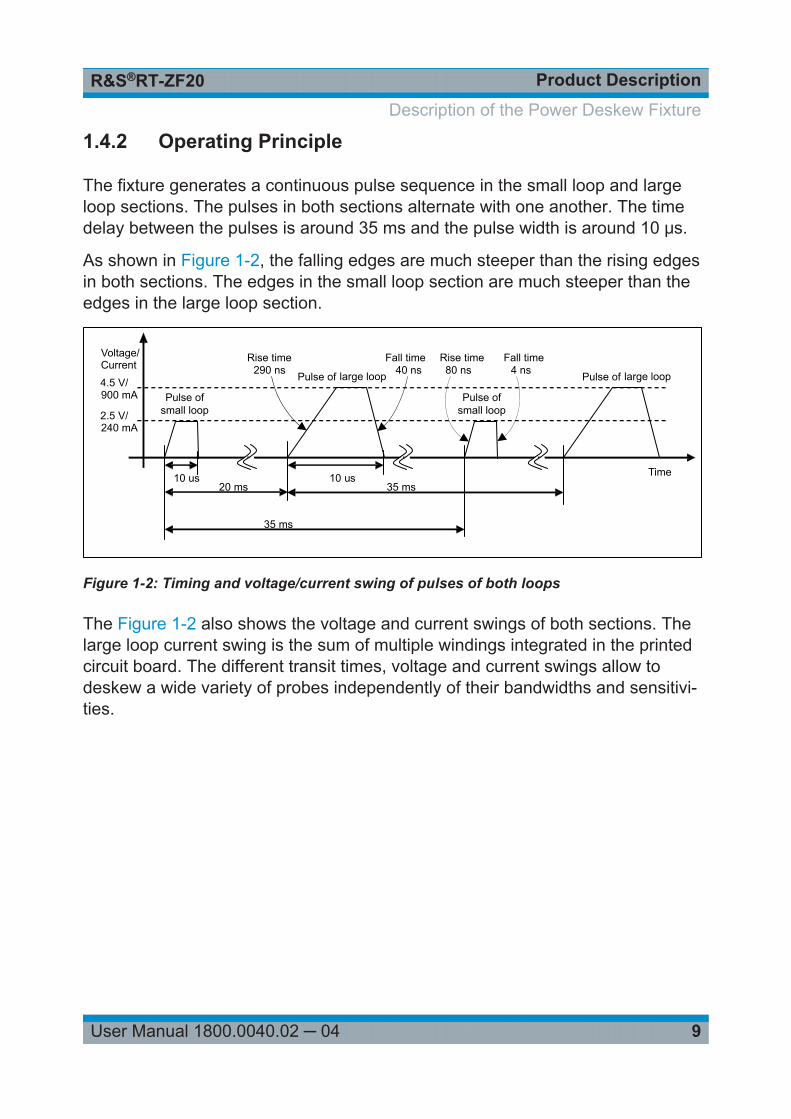
The fixture generates a continuous pulse sequence in the small loop and largeloop sections. The pulses in both sections alternate with one another. The timedelay between the pulses is around 35 ms and the pulse width is around 10 μs.
As shown in Figure 1-2, the falling edges are much steeper than the rising edgesin both sections. The edges in the small loop section are much steeper than theedges in the large loop section.
Pulse of small loop
Pulse of large loop
20 ms
35 ms
35 msTime
Voltage/Current
10 us
2.5 V/240 mA
4.5 V/900 mA
290 ns 40 ns
Pulse of small loop
80 ns 4 ns
10 us
Pulse of large loop
Rise time Rise time Fall timeFall time
Figure 1-2: Timing and voltage/current swing of pulses of both loops
The Figure 1-2 also shows the voltage and current swings of both sections. Thelarge loop current swing is the sum of multiple windings integrated in the printedcircuit board. The different transit times, voltage and current swings allow todeskew a wide variety of probes independently of their bandwidths and sensitivi-ties.
Description of the Power Deskew Fixture

Using the Power Deskew FixtureR&S®RT-ZF20
10User Manual 1800.0040.02 ─ 04
2 Using the Power Deskew Fixture● Connecting the Power.....................................................................................10● Connecting Probes to R&S Oscilloscopes...................................................... 10● Connecting Probes to the Fixture....................................................................11● Deskewing Probes.......................................................................................... 14● Additional Features......................................................................................... 15
2.1 Connecting the Power
The USB connector is used for powering only. The fixture cannot be controlled asa USB device.
► Connect the USB cable to the USB connector of the fixture and to a free USBconnector of any USB host, e.g. R&S oscilloscope, computer or USB hub.The green LED lights up, and the fixture starts pulsing.
2.2 Connecting Probes to R&S Oscilloscopes
1. To connect a R&S RT-ZC10 or R&S RT-ZC20 current probe to the oscillo-scope, e.g. to CH1 input, connect and configure the probe as described in theprobe's user manual.
2. Set the vertical scale for the input channel of the current probe, e.g. CH1:● Large loop, R&S RT-ZC10: 200 mA/div● Small loop, R&S RT-ZC20: 50 mA/div
3. To connect a voltage probe to another channel, e.g. to CH2 input:● If the probe has a read-out pin or an R&S probe box, the channel is config-
ured automatically.● If you use an R&S RT-ZD01 probe, configure the probe as described in the
probe's user manual.
Connecting Probes to R&S Oscilloscopes
Using the Power Deskew FixtureR&S®RT-ZF20
11User Manual 1800.0040.02 ─ 04
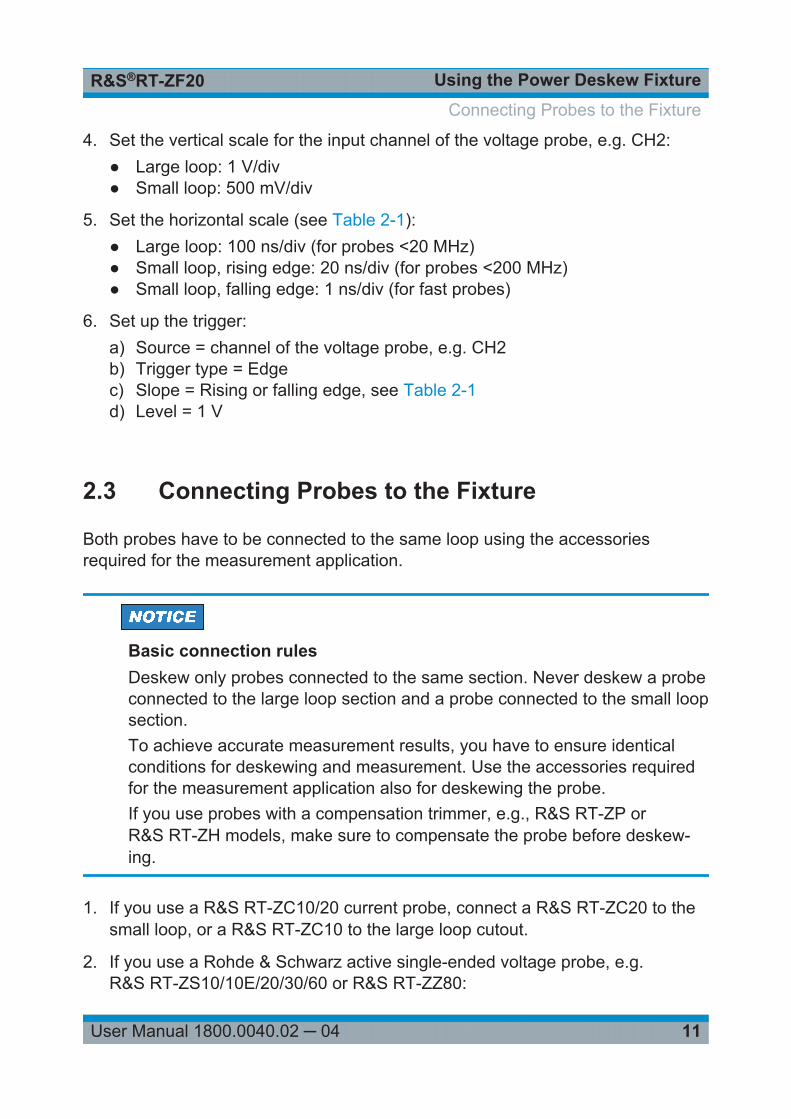
4. Set the vertical scale for the input channel of the voltage probe, e.g. CH2:● Large loop: 1 V/div● Small loop: 500 mV/div
5. Set the horizontal scale (see Table 2-1):● Large loop: 100 ns/div (for probes <20 MHz)● Small loop, rising edge: 20 ns/div (for probes <200 MHz)● Small loop, falling edge: 1 ns/div (for fast probes)
6. Set up the trigger:a) Source = channel of the voltage probe, e.g. CH2b) Trigger type = Edgec) Slope = Rising or falling edge, see Table 2-1d) Level = 1 V
2.3 Connecting Probes to the Fixture
Both probes have to be connected to the same loop using the accessoriesrequired for the measurement application.
Basic connection rulesDeskew only probes connected to the same section. Never deskew a probeconnected to the large loop section and a probe connected to the small loopsection.To achieve accurate measurement results, you have to ensure identicalconditions for deskewing and measurement. Use the accessories requiredfor the measurement application also for deskewing the probe.If you use probes with a compensation trimmer, e.g., R&S RT-ZP orR&S RT-ZH models, make sure to compensate the probe before deskew-ing.
1. If you use a R&S RT-ZC10/20 current probe, connect a R&S RT-ZC20 to thesmall loop, or a R&S RT-ZC10 to the large loop cutout.
2. If you use a Rohde & Schwarz active single-ended voltage probe, e.g.R&S RT-ZS10/10E/20/30/60 or R&S RT-ZZ80:
Connecting Probes to the Fixture

Using the Power Deskew FixtureR&S®RT-ZF20
12User Manual 1800.0040.02 ─ 04
a) Using the square pin adapter, connect the signal socket to the pulse pin.
b) Using the square pin adapter, connect the ground socket to the ground pin.
3. If you use a Rohde & Schwarz differential voltage probe, e.g. R&S RT-ZD20/30/40:a) Connect the positive socket to the pulse pin directly or using the square
pin adapter.b) Connect the negative socket to the ground pin directly or using the
square pin adapter.
Note: The R&S RT-ZD40 cannot be connected directly. Use the square pinadapter to connect this probe.
Connecting Probes to the Fixture

Using the Power Deskew FixtureR&S®RT-ZF20
13User Manual 1800.0040.02 ─ 04
4. If you use a high voltage probe, e.g. R&S RT-ZH10/11, R&S RT-ZD01, or apassive single ended probe, e.g. R&S RT-ZP10:a) Clamp the signal hook/positive hook to the red pulse clamp-on connector.b) Clamp the ground hook/negative hook to the black ground clamp-on con-
nector.
To deskew multiple current probes, use a voltage probe as reference andalign each current probe with the reference voltage probe.
Figure 2-1: R&S RT-ZC10 and R&S RT-ZD30 differential probe at large loop
Connecting Probes to the Fixture

Using the Power Deskew FixtureR&S®RT-ZF20
14User Manual 1800.0040.02 ─ 04
2.4 Deskewing Probes
Deskewing means to align the edges of two waveforms output by two differentprobes. Therefore, skew offset is set to one of the used input channels. Use thefollowing transition depending on the probe with the smallest bandwidth.
Table 2-1: Transition and probe dependencies
Probe Transition
R&S RT-ZC10Any other probe with bandwidth <20 MHzFaster probe with 20 MHz bandwidth filter
Large loopRising edge
R&S RT-ZC20 or R&S RT-ZD01Any other probe with bandwidth <200 MHzFaster probe with 200 MHz bandwidth filter
Small loopRising edge
Other probes Small loopFalling edge
Figure 2-2: Deskewing
Left = no skew offset, time delay between waveformsRight = skew offset set, aligned waveforms
Deskewing with R&S RTO
1. On the "Vertical" menu, tap "Probe Setup".
2. Tap the "Deskew" button.
3. Tap "Skew offset".
Deskewing Probes
Using the Power Deskew FixtureR&S®RT-ZF20
15User Manual 1800.0040.02 ─ 04
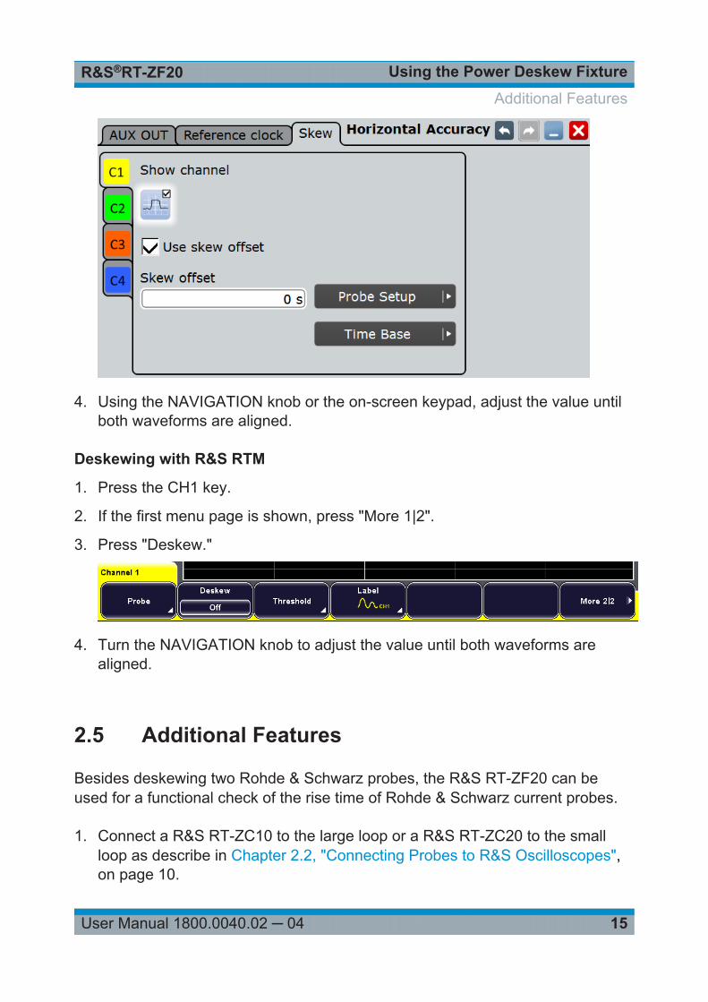
4. Using the NAVIGATION knob or the on-screen keypad, adjust the value untilboth waveforms are aligned.
Deskewing with R&S RTM
1. Press the CH1 key.
2. If the first menu page is shown, press "More 1|2".
3. Press "Deskew."
4. Turn the NAVIGATION knob to adjust the value until both waveforms arealigned.
2.5 Additional Features
Besides deskewing two Rohde & Schwarz probes, the R&S RT-ZF20 can beused for a functional check of the rise time of Rohde & Schwarz current probes.
1. Connect a R&S RT-ZC10 to the large loop or a R&S RT-ZC20 to the smallloop as describe in Chapter 2.2, "Connecting Probes to R&S Oscilloscopes",on page 10.
Additional Features

Using the Power Deskew FixtureR&S®RT-ZF20
16User Manual 1800.0040.02 ─ 04
2. Adjust the trigger to the falling edge.
3. Enable a fall time measurement for the channel connected to the currentprobe.
4. Set the relative reference levels to "20/50/80".
The measured fall time should be around 5 ns for R&S RT-ZC20 and around50 ns for R&S RT-ZC10.
Additional Features