R&S®ZNBT8 Vector Network Analyzer - Test … · Switching time between channels with a maximum of...
16
Test & Measurement Data Sheet | 02.00 R&S®ZNBT8 Vector Network Analyzer Specifications Advanced Test Equipment Rentals www.atecorp.com 800-404-ATEC (2832) ® E s t a blishe d 1 9 8 1
Transcript of R&S®ZNBT8 Vector Network Analyzer - Test … · Switching time between channels with a maximum of...
Te
st &
Mea
sure
men
t
Data
She
et |
02.0
0
R&S®ZNBT8Vector Network AnalyzerSpecifications
ZNBT8_dat-sw_en_3606-9727-22_v0200_cover.indd 1 20.05.2014 08:39:42
Advanced Test Equipment Rentalswww.atecorp.com 800-404-ATEC (2832)
®
Established 1981
Version 02.00, May 2014
2 Rohde & Schwarz R&S®ZNBT8 Vector Network Analyzer
CONTENTS Definitions ....................................................................................................................................................................... 3 Measurement range ........................................................................................................................................................ 4 Measurement speed........................................................................................................................................................ 5 Measurement accuracy .................................................................................................................................................. 7 Effective system data ..................................................................................................................................................... 8 Factory-calibrated system data ..................................................................................................................................... 8 Test port output .............................................................................................................................................................. 9 Test port input ............................................................................................................................................................... 10 Additional front panel connectors ............................................................................................................................... 10 Display ........................................................................................................................................................................... 10 Rear panel connectors ................................................................................................................................................. 10 Options .......................................................................................................................................................................... 12
R&S®ZNBT8-B4 .................................................................................................................................................................................... 12 R&S®ZNBT8-B10 .................................................................................................................................................................................. 12 R&S®ZNBT8-B12 .................................................................................................................................................................................. 12 R&S®ZNBT8-B21/-B22/-B23/-B24/-B25/-B26 ....................................................................................................................................... 12 R&S®ZNBT8-B361/-B362/-B363/-B364/-B365/-B366 ........................................................................................................................... 12 R&S®ZNBT8-B81 .................................................................................................................................................................................. 12
General data .................................................................................................................................................................. 13 Dimensions (in mm) ...................................................................................................................................................... 14 Ordering information .................................................................................................................................................... 15
Version 02.00, May 2014
Rohde & Schwarz R&S®ZNBT8 Vector Network Analyzer 3
Definitions General Product data applies under the following conditions:
• Three hours storage at ambient temperature followed by 60 minutes warm-up operation • Specified environmental conditions met • Recommended calibration interval adhered to • All internal automatic adjustments performed, if applicable • Unless stated otherwise, specifications apply to test ports and a nominal source power of –10 dBm
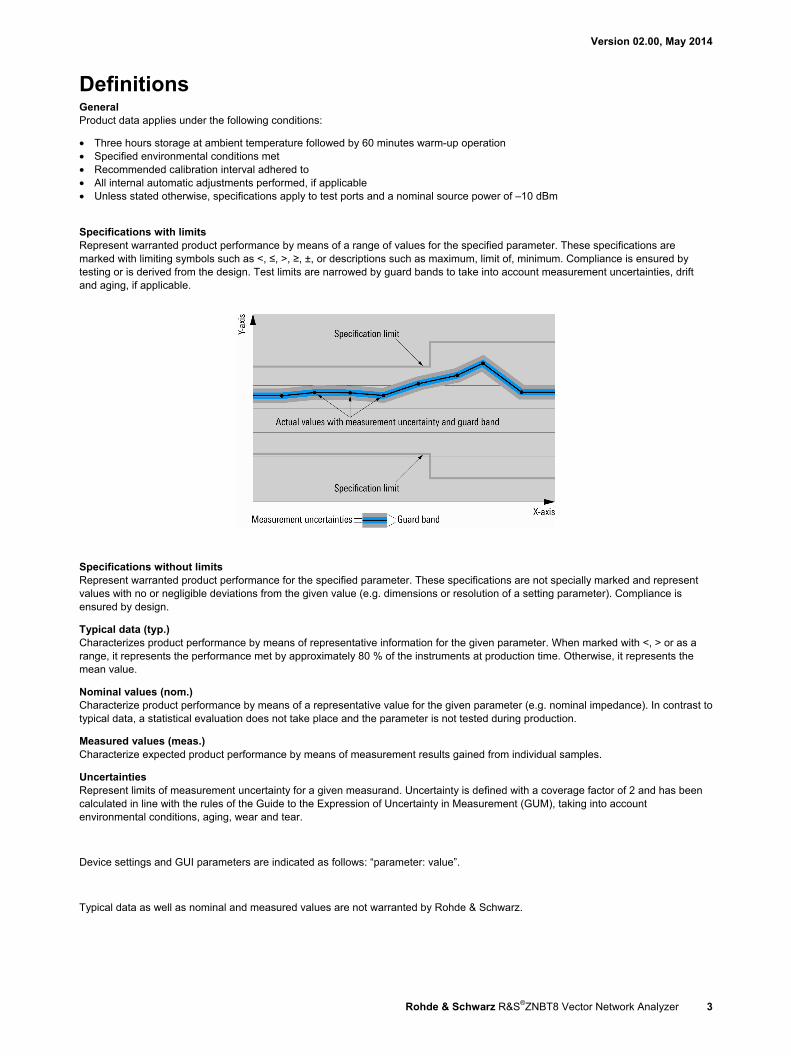
Specifications with limits Represent warranted product performance by means of a range of values for the specified parameter. These specifications are marked with limiting symbols such as <, ≤, >, ≥, ±, or descriptions such as maximum, limit of, minimum. Compliance is ensured by testing or is derived from the design. Test limits are narrowed by guard bands to take into account measurement uncertainties, drift and aging, if applicable.
Specifications without limits Represent warranted product performance for the specified parameter. These specifications are not specially marked and represent values with no or negligible deviations from the given value (e.g. dimensions or resolution of a setting parameter). Compliance is ensured by design.
Typical data (typ.) Characterizes product performance by means of representative information for the given parameter. When marked with <, > or as a range, it represents the performance met by approximately 80 % of the instruments at production time. Otherwise, it represents the mean value.
Nominal values (nom.) Characterize product performance by means of a representative value for the given parameter (e.g. nominal impedance). In contrast to typical data, a statistical evaluation does not take place and the parameter is not tested during production.
Measured values (meas.) Characterize expected product performance by means of measurement results gained from individual samples.
Uncertainties Represent limits of measurement uncertainty for a given measurand. Uncertainty is defined with a coverage factor of 2 and has been calculated in line with the rules of the Guide to the Expression of Uncertainty in Measurement (GUM), taking into account environmental conditions, aging, wear and tear.
Device settings and GUI parameters are indicated as follows: “parameter: value”.
Typical data as well as nominal and measured values are not warranted by Rohde & Schwarz.
Version 02.00, May 2014
4 Rohde & Schwarz R&S®ZNBT8 Vector Network Analyzer
Measurement range Impedance 50 Ω Test port connector N female Number of test ports (the R&S®ZNBT8 supports simultaneous data acquisition at all test ports)
base unit 4 with R&S®ZNBT8-B108 option (additional ports 5 to 8)
8
with R&S®ZNBT8-B112 option (additional ports 9 to 12)
12
with R&S®ZNBT8-B116 option (additional ports 13 to 16)
16
with R&S®ZNBT8-B120 option (additional ports 17 to 20)
20
with R&S®ZNBT8-B124 option (additional ports 21 to 24)
24
Frequency range 9 kHz to 8.5 GHz
Static frequency accuracy (time since last adjustment × aging rate) + temperature drift + calibration accuracy
Aging per year standard ±1 × 10⁻⁶ with R&S®ZNBT8-B4 precision frequency reference option
±1 × 10⁻⁷
Temperature drift (0 °C to +40 °C) standard ±1 × 10⁻⁶ with R&S®ZNBT8-B4 precision frequency reference option
±1 × 10⁻⁸
Achievable initial calibration accuracy standard ±5 × 10⁻⁷ with R&S®ZNB-B4 precision frequency reference option
±5 × 10⁻⁸
Frequency resolution 1 Hz Number of measurement points 1 per trace 2 to 100001 Measurement bandwidth 1/1.5/2/3/5/7 steps
without optional increased bandwidth 1 Hz to 1 MHz with optional increased bandwidth 1 Hz to 10 MHz
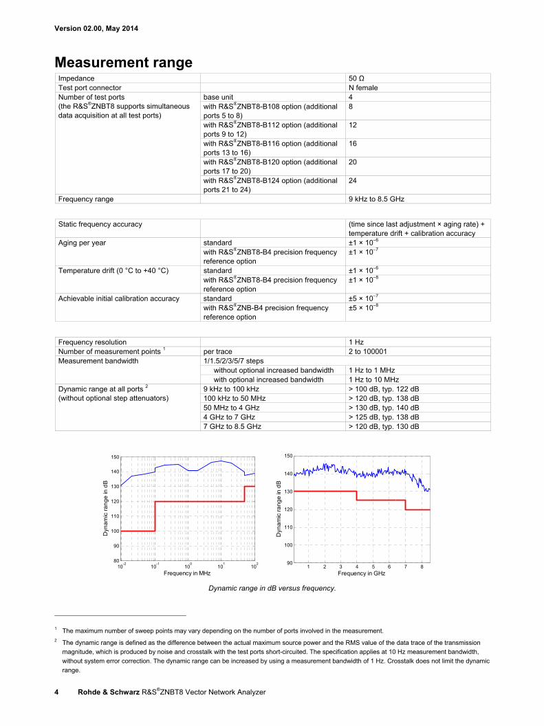
Dynamic range at all ports 2 (without optional step attenuators)
9 kHz to 100 kHz > 100 dB, typ. 122 dB 100 kHz to 50 MHz > 120 dB, typ. 138 dB 50 MHz to 4 GHz > 130 dB, typ. 140 dB 4 GHz to 7 GHz > 125 dB, typ. 138 dB 7 GHz to 8.5 GHz > 120 dB, typ. 130 dB
Dynamic range in dB versus frequency.
1 The maximum number of sweep points may vary depending on the number of ports involved in the measurement. 2 The dynamic range is defined as the difference between the actual maximum source power and the RMS value of the data trace of the transmission
magnitude, which is produced by noise and crosstalk with the test ports short-circuited. The specification applies at 10 Hz measurement bandwidth,
without system error correction. The dynamic range can be increased by using a measurement bandwidth of 1 Hz. Crosstalk does not limit the dynamic
range.
10-2
10-1
100
101
102
80
90
100
110
120
130
140
150
Frequency in MHz
Dyn
am
ic r
an
ge
in d
B
1 2 3 4 5 6 7 890
100
110
120
130
140
150
Frequency in GHz
Dyn
am
ic r
an
ge
in d
B
Version 02.00, May 2014
Rohde & Schwarz R&S®ZNBT8 Vector Network Analyzer 5
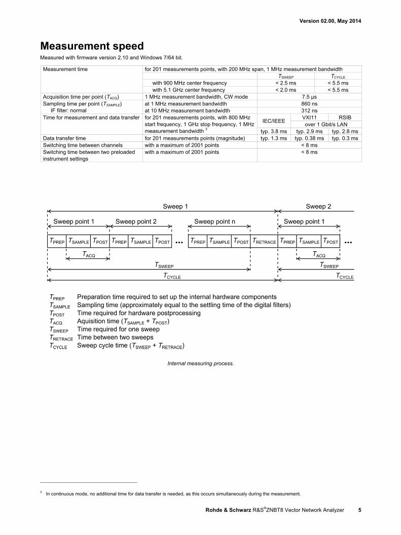
Measurement speed Measured with firmware version 2.10 and Windows 7/64 bit.
Measurement time for 201 measurements points, with 200 MHz span, 1 MHz measurement bandwidth TSWEEP TCYCLE
with 900 MHz center frequency < 2.5 ms < 5.5 ms with 5.1 GHz center frequency < 2.0 ms < 5.5 ms
Acquisition time per point (TACQ) 1 MHz measurement bandwidth, CW mode 7.5 µs Sampling time per point (TSAMPLE)
IF filter: normal at 1 MHz measurement bandwidth 860 ns at 10 MHz measurement bandwidth 312 ns
Time for measurement and data transfer for 201 measurements points, with 800 MHz start frequency, 1 GHz stop frequency, 1 MHz measurement bandwidth 3
IEC/IEEE VXI11 RSIB over 1 Gbit/s LAN
typ. 3.8 ms typ. 2.9 ms typ. 2.8 ms Data transfer time for 201 measurements points (magnitude) typ. 1.3 ms typ. 0.38 ms typ. 0.3 ms Switching time between channels with a maximum of 2001 points < 8 ms Switching time between two preloaded instrument settings
with a maximum of 2001 points < 8 ms
Internal measuring process.
3 In continuous mode, no additional time for data transfer is needed, as this occurs simultaneously during the measurement.
Version 02.00, May 2014
6 Rohde & Schwarz R&S®ZNBT8 Vector Network Analyzer
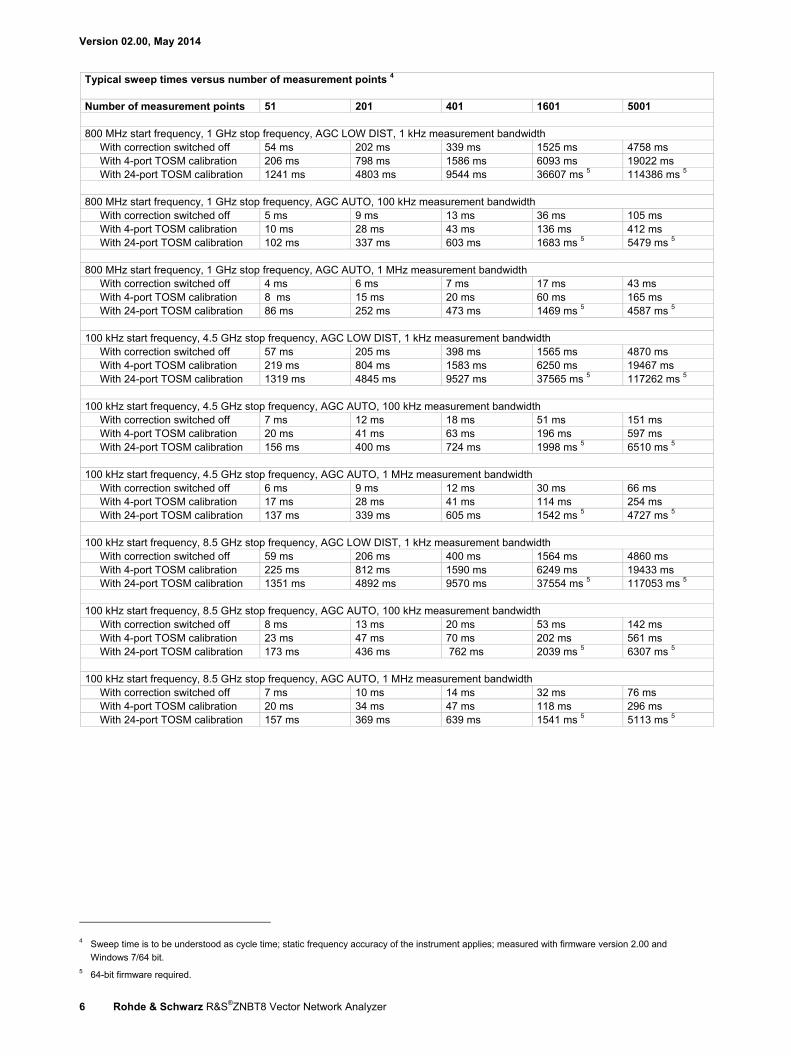
Typical sweep times versus number of measurement points 4 Number of measurement points 51 201 401 1601 5001 800 MHz start frequency, 1 GHz stop frequency, AGC LOW DIST, 1 kHz measurement bandwidth
With correction switched off 54 ms 202 ms 339 ms 1525 ms 4758 ms With 4-port TOSM calibration 206 ms 798 ms 1586 ms 6093 ms 19022 ms With 24-port TOSM calibration 1241 ms 4803 ms 9544 ms 36607 ms 5 114386 ms 5
800 MHz start frequency, 1 GHz stop frequency, AGC AUTO, 100 kHz measurement bandwidth With correction switched off 5 ms 9 ms 13 ms 36 ms 105 ms With 4-port TOSM calibration 10 ms 28 ms 43 ms 136 ms 412 ms With 24-port TOSM calibration 102 ms 337 ms 603 ms 1683 ms 5 5479 ms 5
800 MHz start frequency, 1 GHz stop frequency, AGC AUTO, 1 MHz measurement bandwidth With correction switched off 4 ms 6 ms 7 ms 17 ms 43 ms With 4-port TOSM calibration 8 ms 15 ms 20 ms 60 ms 165 ms With 24-port TOSM calibration 86 ms 252 ms 473 ms 1469 ms 5 4587 ms 5
100 kHz start frequency, 4.5 GHz stop frequency, AGC LOW DIST, 1 kHz measurement bandwidth With correction switched off 57 ms 205 ms 398 ms 1565 ms 4870 ms With 4-port TOSM calibration 219 ms 804 ms 1583 ms 6250 ms 19467 ms With 24-port TOSM calibration 1319 ms 4845 ms 9527 ms 37565 ms 5 117262 ms 5
100 kHz start frequency, 4.5 GHz stop frequency, AGC AUTO, 100 kHz measurement bandwidth With correction switched off 7 ms 12 ms 18 ms 51 ms 151 ms With 4-port TOSM calibration 20 ms 41 ms 63 ms 196 ms 597 ms With 24-port TOSM calibration 156 ms 400 ms 724 ms 1998 ms 5 6510 ms 5
100 kHz start frequency, 4.5 GHz stop frequency, AGC AUTO, 1 MHz measurement bandwidth With correction switched off 6 ms 9 ms 12 ms 30 ms 66 ms With 4-port TOSM calibration 17 ms 28 ms 41 ms 114 ms 254 ms With 24-port TOSM calibration 137 ms 339 ms 605 ms 1542 ms 5 4727 ms 5
100 kHz start frequency, 8.5 GHz stop frequency, AGC LOW DIST, 1 kHz measurement bandwidth With correction switched off 59 ms 206 ms 400 ms 1564 ms 4860 ms With 4-port TOSM calibration 225 ms 812 ms 1590 ms 6249 ms 19433 ms With 24-port TOSM calibration 1351 ms 4892 ms 9570 ms 37554 ms 5 117053 ms 5
100 kHz start frequency, 8.5 GHz stop frequency, AGC AUTO, 100 kHz measurement bandwidth With correction switched off 8 ms 13 ms 20 ms 53 ms 142 ms With 4-port TOSM calibration 23 ms 47 ms 70 ms 202 ms 561 ms With 24-port TOSM calibration 173 ms 436 ms 762 ms 2039 ms 5 6307 ms 5
100 kHz start frequency, 8.5 GHz stop frequency, AGC AUTO, 1 MHz measurement bandwidth With correction switched off 7 ms 10 ms 14 ms 32 ms 76 ms With 4-port TOSM calibration 20 ms 34 ms 47 ms 118 ms 296 ms With 24-port TOSM calibration 157 ms 369 ms 639 ms 1541 ms 5 5113 ms 5
4 Sweep time is to be understood as cycle time; static frequency accuracy of the instrument applies; measured with firmware version 2.00 and
Windows 7/64 bit. 5 64-bit firmware required.
Version 02.00, May 2014
Rohde & Schwarz R&S®ZNBT8 Vector Network Analyzer 7
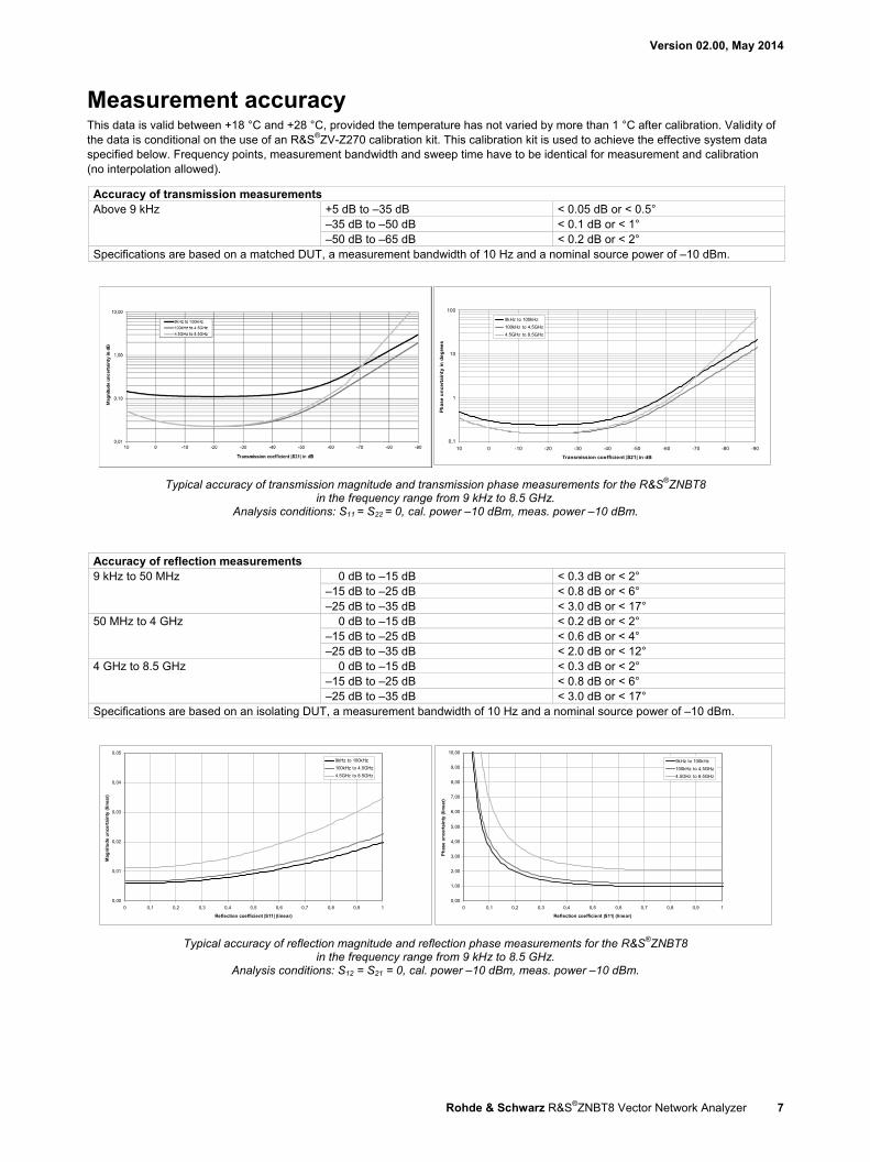
Measurement accuracy This data is valid between +18 °C and +28 °C, provided the temperature has not varied by more than 1 °C after calibration. Validity of the data is conditional on the use of an R&S®ZV-Z270 calibration kit. This calibration kit is used to achieve the effective system data specified below. Frequency points, measurement bandwidth and sweep time have to be identical for measurement and calibration (no interpolation allowed).
Accuracy of transmission measurements Above 9 kHz +5 dB to –35 dB < 0.05 dB or < 0.5°
–35 dB to –50 dB < 0.1 dB or < 1° –50 dB to –65 dB < 0.2 dB or < 2°
Specifications are based on a matched DUT, a measurement bandwidth of 10 Hz and a nominal source power of –10 dBm.
Typical accuracy of transmission magnitude and transmission phase measurements for the R&S®ZNBT8 in the frequency range from 9 kHz to 8.5 GHz.
Analysis conditions: S11 = S22 = 0, cal. power –10 dBm, meas. power –10 dBm.
Accuracy of reflection measurements 9 kHz to 50 MHz 0 dB to –15 dB < 0.3 dB or < 2°
–15 dB to –25 dB < 0.8 dB or < 6° –25 dB to –35 dB < 3.0 dB or < 17°
50 MHz to 4 GHz 0 dB to –15 dB < 0.2 dB or < 2° –15 dB to –25 dB < 0.6 dB or < 4° –25 dB to –35 dB < 2.0 dB or < 12°
4 GHz to 8.5 GHz 0 dB to –15 dB < 0.3 dB or < 2° –15 dB to –25 dB < 0.8 dB or < 6° –25 dB to –35 dB < 3.0 dB or < 17°
Specifications are based on an isolating DUT, a measurement bandwidth of 10 Hz and a nominal source power of –10 dBm.
Typical accuracy of reflection magnitude and reflection phase measurements for the R&S®ZNBT8 in the frequency range from 9 kHz to 8.5 GHz.
Analysis conditions: S12 = S21 = 0, cal. power –10 dBm, meas. power –10 dBm.
0,1
1
10
100
-90-80-70-60-50-40-30-20-10010
Transmission coefficient |S21| in dB
Ph
as
e u
nc
erta
inty
in
de
gre
es
9kHz to 100kHz
100kHz to 4.5GHz
4.5GHz to 8.5GHz
0,00
0,01
0,02
0,03
0,04
0,05
0 0,1 0,2 0,3 0,4 0,5 0,6 0,7 0,8 0,9 1
Reflection coefficient |S11| (linear)
Mag
nit
ud
e u
nce
rtai
nty
(li
nea
r)
9kHz to 100kHz
100kHz to 4.5GHz
4.5GHz to 8.5GHz
0,00
1,00
2,00
3,00
4,00
5,00
6,00
7,00
8,00
9,00
10,00
0 0,1 0,2 0,3 0,4 0,5 0,6 0,7 0,8 0,9 1
Reflection coefficient |S11| (linear)
Ph
ase
un
cert
ain
ty (
lin
ear)
9kHz to 100kHz
100kHz to 4.5GHz
4.5GHz to 8.5GHz
Version 02.00, May 2014
8 Rohde & Schwarz R&S®ZNBT8 Vector Network Analyzer
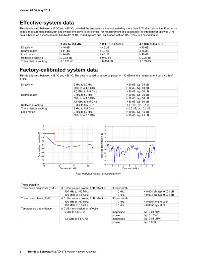
Effective system data This data is valid between +18 °C and +28 °C, provided the temperature has not varied by more than 1 °C after calibration. Frequency points, measurement bandwidth and sweep time have to be identical for measurement and calibration (no interpolation allowed).The data is based on a measurement bandwidth of 10 Hz and system error calibration with an R&S®ZV-Z270 calibration kit.
9 kHz to 100 kHz 100 kHz to 4.5 GHz 4.5 GHz to 8.5 GHz Directivity ≥ 46 dB ≥ 45 dB ≥ 40 dB Source match ≥ 41 dB ≥ 40 dB ≥ 36 dB Load match ≥ 44 dB ≥ 45 dB ≥ 40 dB Reflection tracking ≤ 0.02 dB ≤ 0.02 dB ≤ 0.05 dB Transmission tracking ≤ 0.028 dB ≤ 0.018 dB ≤ 0.09 dB
Factory-calibrated system data This data is valid between +18 °C and +28 °C. The data is based on a source power of –10 dBm and a measurement bandwidth of 1 kHz.
Directivity 9 kHz to 50 kHz > 20 dB, typ. 35 dB 50 kHz to 4.5 GHz > 30 dB, typ. 50 dB 4.5 GHz to 8.5 GHz > 30 dB, typ. 50 dB
Source match 9 kHz to 50 kHz > 20 dB, typ. 35 dB 50 kHz to 4.5 GHz > 30 dB, typ. 50 dB 4.5 GHz to 8.5 GHz > 30 dB, typ. 50 dB
Reflection tracking 9 kHz to 8.5 GHz < 0.5 dB, typ. 0.1 dB Transmission tracking 9 kHz to 8.5 GHz < 0.5 dB, typ. 0.1 dB Load match 9 kHz to 50 kHz > 10 dB, typ. 15 dB
50 kHz to 8.5 GHz > 20 dB, typ. 25 dB
Raw load port match versus frequency.
Trace stability Trace noise magnitude (RMS) at 0 dBm source power, 0 dB reflection IF bandwidth
100 kHz to 100 MHz 10 kHz < 0.004 dB, typ. 0.001 dB 100 MHz to 8.5 GHz 10 kHz < 0.004 dB, typ. 0.002 dB
Trace noise phase (RMS) at 0 dBm source power, 0 dB reflection IF bandwidth 100 kHz to 100 MHz 10 kHz < 0.035°, typ. 0.005° 100 MHz to 8.5 GHz 10 kHz < 0.035°, typ. 0.02°
Temperature dependence at 0 dB transmission or reflection 9 kHz to 4.5 GHz
magnitude typ. 0.01 dB/K phase typ. 0.15°/K
4.5 GHz to 8.5 GHz magnitude typ. 0.04 dB/K phase typ. 0.8°/K
10-2
10-1
100
101
-50
-45
-40
-35
-30
-25
-20
-15
-10
-5
0
Frequency in MHz
Ra
w lo
ad
po
rt m
atc
h in
dB
1 2 3 4 5 6 7 8-50
-45
-40
-35
-30
-25
-20
-15
-10
-5
0
Frequency in GHz
Ra
w lo
ad
po
rt m
atc
h in
dB
Version 02.00, May 2014
Rohde & Schwarz R&S®ZNBT8 Vector Network Analyzer 9
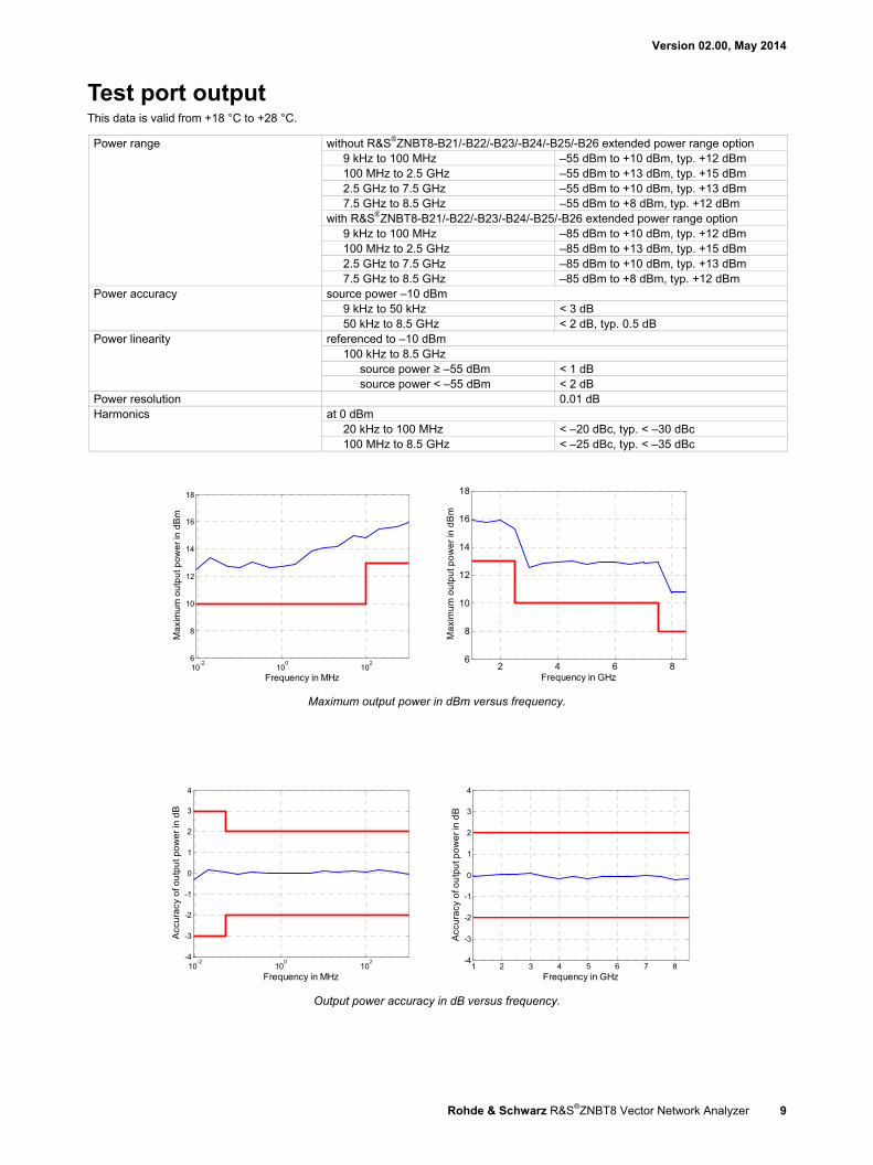
Test port output This data is valid from +18 °C to +28 °C.
Power range without R&S®ZNBT8-B21/-B22/-B23/-B24/-B25/-B26 extended power range option 9 kHz to 100 MHz –55 dBm to +10 dBm, typ. +12 dBm 100 MHz to 2.5 GHz –55 dBm to +13 dBm, typ. +15 dBm 2.5 GHz to 7.5 GHz –55 dBm to +10 dBm, typ. +13 dBm 7.5 GHz to 8.5 GHz –55 dBm to +8 dBm, typ. +12 dBm
with R&S®ZNBT8-B21/-B22/-B23/-B24/-B25/-B26 extended power range option 9 kHz to 100 MHz –85 dBm to +10 dBm, typ. +12 dBm 100 MHz to 2.5 GHz –85 dBm to +13 dBm, typ. +15 dBm 2.5 GHz to 7.5 GHz –85 dBm to +10 dBm, typ. +13 dBm 7.5 GHz to 8.5 GHz –85 dBm to +8 dBm, typ. +12 dBm
Power accuracy source power –10 dBm 9 kHz to 50 kHz < 3 dB 50 kHz to 8.5 GHz < 2 dB, typ. 0.5 dB
Power linearity referenced to –10 dBm 100 kHz to 8.5 GHz
source power ≥ –55 dBm < 1 dB source power < –55 dBm < 2 dB
Power resolution 0.01 dB Harmonics at 0 dBm
20 kHz to 100 MHz < –20 dBc, typ. < –30 dBc 100 MHz to 8.5 GHz < –25 dBc, typ. < –35 dBc
Maximum output power in dBm versus frequency.
Output power accuracy in dB versus frequency.
10-2
100
102
6
8
10
12
14
16
18
Frequency in MHz
Ma
xim
um
ou
tpu
t po
we
r in
dB
m
2 4 6 86
8
10
12
14
16
18
Frequency in GHz
Ma
xim
um
ou
tpu
t po
we
r in
dB
m
10-2
100
102
-4
-3
-2
-1
0
1
2
3
4
Frequency in MHz
Acc
ura
cy o
f ou
tpu
t po
we
r in
dB
1 2 3 4 5 6 7 8-4
-3
-2
-1
0
1
2
3
4
Frequency in GHz
Acc
ura
cy o
f ou
tpu
t po
we
r in
dB
Version 02.00, May 2014
10 Rohde & Schwarz R&S®ZNBT8 Vector Network Analyzer
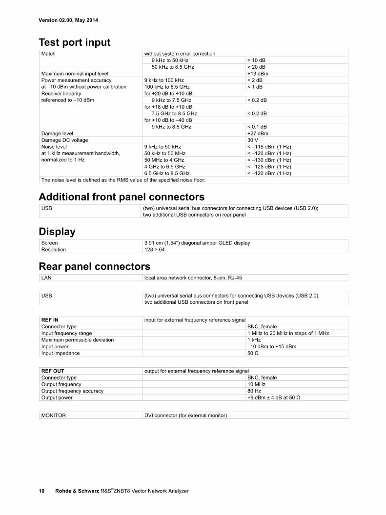
Test port input Match without system error correction
9 kHz to 50 kHz > 10 dB 50 kHz to 8.5 GHz > 20 dB
Maximum nominal input level +13 dBm Power measurement accuracy at –10 dBm without power calibration
9 kHz to 100 kHz < 2 dB 100 kHz to 8.5 GHz < 1 dB
Receiver linearity referenced to –10 dBm
for +20 dB to +10 dB 9 kHz to 7.5 GHz < 0.2 dB
for +18 dB to +10 dB 7.5 GHz to 8.5 GHz < 0.2 dB
for +10 dB to –40 dB 9 kHz to 8.5 GHz < 0.1 dB
Damage level +27 dBm Damage DC voltage 30 V Noise level at 1 kHz measurement bandwidth, normalized to 1 Hz
9 kHz to 50 kHz < –115 dBm (1 Hz) 50 kHz to 50 MHz < –120 dBm (1 Hz) 50 MHz to 4 GHz < –130 dBm (1 Hz) 4 GHz to 6.5 GHz < –125 dBm (1 Hz) 6.5 GHz to 8.5 GHz < –120 dBm (1 Hz)
The noise level is defined as the RMS value of the specified noise floor.
Additional front panel connectors USB (two) universal serial bus connectors for connecting USB devices (USB 2.0);
two additional USB connectors on rear panel
Display Screen 3.91 cm (1.54") diagonal amber OLED display Resolution 128 × 64
Rear panel connectors LAN local area network connector, 8-pin, RJ-45
USB (two) universal serial bus connectors for connecting USB devices (USB 2.0); two additional USB connectors on front panel
REF IN input for external frequency reference signal Connector type BNC, female Input frequency range 1 MHz to 20 MHz in steps of 1 MHz Maximum permissible deviation 1 kHz Input power –10 dBm to +15 dBm Input impedance 50 Ω
REF OUT output for external frequency reference signal Connector type BNC, female Output frequency 10 MHz Output frequency accuracy 80 Hz Output power +9 dBm ± 4 dB at 50 Ω
MONITOR DVI connector (for external monitor)
Version 02.00, May 2014
Rohde & Schwarz R&S®ZNBT8 Vector Network Analyzer 11
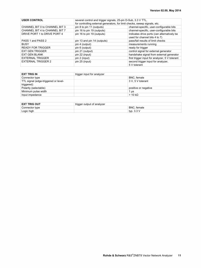
USER CONTROL several control and trigger signals, 25-pin D-Sub, 3.3 V TTL, for controlling external generators, for limit checks, sweep signals, etc.
CHANNEL BIT 0 to CHANNEL BIT 3 pin 8 to pin 11 (outputs) channel-specific, user-configurable bits CHANNEL BIT 4 to CHANNEL BIT 7 pin 16 to pin 19 (outputs) channel-specific, user-configurable bits DRIVE PORT 1 to DRIVE PORT 4 pin 16 to pin 19 (outputs) indicates drive ports (can alternatively be
used for channel bits 4 to 7) PASS 1 and PASS 2 pin 13 and pin 14 (outputs) pass/fail results of limit checks BUSY pin 4 (output) measurements running READY FOR TRIGGER pin 6 (output) ready for trigger EXT GEN TRIGGER pin 21 (output) control signal for external generator EXT GEN BLANK pin 22 (input) handshake signal from external generator EXTERNAL TRIGGER pin 2 (input) first trigger input for analyzer, 5 V tolerant EXTERNAL TRIGGER 2 pin 25 (input) second trigger input for analyzer,
5 V tolerant
EXT TRIG IN trigger input for analyzer Connector type BNC, female TTL signal (edge-triggered or level-triggered)
3 V, 5 V tolerant
Polarity (selectable) positive or negative Minimum pulse width 1 µs Input impedance > 10 kΩ
EXT TRIG OUT trigger output of analyzer Connector type BNC, female Logic high typ. 3.3 V
Version 02.00, May 2014
12 Rohde & Schwarz R&S®ZNBT8 Vector Network Analyzer
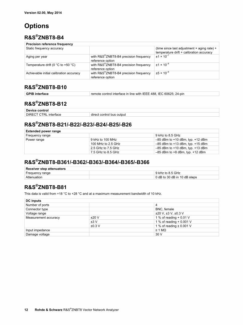
Options
R&S®ZNBT8-B4 Precision reference frequency Static frequency accuracy (time since last adjustment × aging rate) +
temperature drift + calibration accuracy Aging per year with R&S®ZNBT8-B4 precision frequency
reference option ±1 × 10⁻⁷
Temperature drift (0 °C to +50 °C) with R&S®ZNBT8-B4 precision frequency reference option
±1 × 10⁻⁸
Achievable initial calibration accuracy with R&S®ZNBT8-B4 precision frequency reference option
±5 × 10⁻⁸
R&S®ZNBT8-B10 GPIB interface remote control interface in line with IEEE 488, IEC 60625; 24-pin
R&S®ZNBT8-B12 Device control DIRECT CTRL interface direct control bus output
R&S®ZNBT8-B21/-B22/-B23/-B24/-B25/-B26 Extended power range Frequency range 9 kHz to 8.5 GHz Power range 9 kHz to 100 MHz –85 dBm to +10 dBm, typ. +12 dBm
100 MHz to 2.5 GHz –85 dBm to +13 dBm, typ. +15 dBm 2.5 GHz to 7.5 GHz –85 dBm to +10 dBm, typ. +13 dBm 7.5 GHz to 8.5 GHz –85 dBm to +8 dBm, typ. +12 dBm
R&S®ZNBT8-B361/-B362/-B363/-B364/-B365/-B366 Receiver step attenuators Frequency range 9 kHz to 8.5 GHz Attenuation 0 dB to 30 dB in 10 dB steps
R&S®ZNBT8-B81 This data is valid from +18 °C to +28 °C and at a maximum measurement bandwidth of 10 kHz.
DC inputs Number of ports 4 Connector type BNC, female Voltage range ±20 V, ±3 V, ±0.3 V Measurement accuracy ±20 V 1 % of reading + 0.01 V
±3 V 1 % of reading + 0.001 V ±0.3 V 1 % of reading ± 0.001 V
Input impedance ≥ 1 MΩ Damage voltage 30 V
Version 02.00, May 2014
Rohde & Schwarz R&S®ZNBT8 Vector Network Analyzer 13
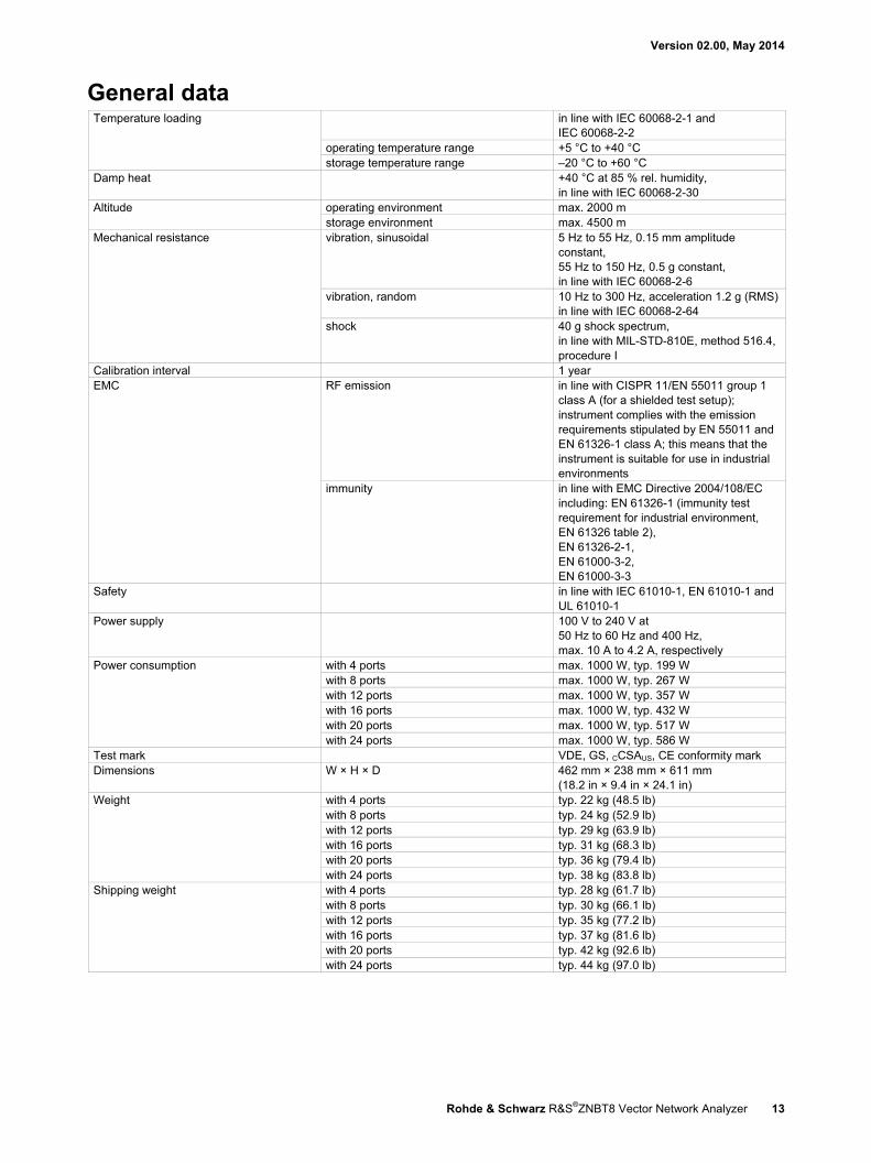
General data Temperature loading in line with IEC 60068-2-1 and
IEC 60068-2-2 operating temperature range +5 °C to +40 °C storage temperature range –20 °C to +60 °C
Damp heat +40 °C at 85 % rel. humidity, in line with IEC 60068-2-30
Altitude operating environment max. 2000 m storage environment max. 4500 m
Mechanical resistance vibration, sinusoidal 5 Hz to 55 Hz, 0.15 mm amplitude constant, 55 Hz to 150 Hz, 0.5 g constant, in line with IEC 60068-2-6
vibration, random 10 Hz to 300 Hz, acceleration 1.2 g (RMS) in line with IEC 60068-2-64
shock 40 g shock spectrum, in line with MIL-STD-810E, method 516.4, procedure I
Calibration interval 1 year EMC RF emission in line with CISPR 11/EN 55011 group 1
class A (for a shielded test setup); instrument complies with the emission requirements stipulated by EN 55011 and EN 61326-1 class A; this means that the instrument is suitable for use in industrial environments
immunity in line with EMC Directive 2004/108/EC including: EN 61326-1 (immunity test requirement for industrial environment, EN 61326 table 2), EN 61326-2-1, EN 61000-3-2, EN 61000-3-3
Safety in line with IEC 61010-1, EN 61010-1 and UL 61010-1
Power supply 100 V to 240 V at 50 Hz to 60 Hz and 400 Hz, max. 10 A to 4.2 A, respectively
Power consumption with 4 ports max. 1000 W, typ. 199 W with 8 ports max. 1000 W, typ. 267 W with 12 ports max. 1000 W, typ. 357 W with 16 ports max. 1000 W, typ. 432 W with 20 ports max. 1000 W, typ. 517 W with 24 ports max. 1000 W, typ. 586 W
Test mark VDE, GS, CCSAUS, CE conformity mark Dimensions W × H × D 462 mm × 238 mm × 611 mm
(18.2 in × 9.4 in × 24.1 in) Weight with 4 ports typ. 22 kg (48.5 lb)
with 8 ports typ. 24 kg (52.9 lb) with 12 ports typ. 29 kg (63.9 lb) with 16 ports typ. 31 kg (68.3 lb) with 20 ports typ. 36 kg (79.4 lb) with 24 ports typ. 38 kg (83.8 lb)
Shipping weight with 4 ports typ. 28 kg (61.7 lb) with 8 ports typ. 30 kg (66.1 lb) with 12 ports typ. 35 kg (77.2 lb) with 16 ports typ. 37 kg (81.6 lb) with 20 ports typ. 42 kg (92.6 lb) with 24 ports typ. 44 kg (97.0 lb)
Version 02.00, May 2014
14 Rohde & Schwarz R&S®ZNBT8 Vector Network Analyzer
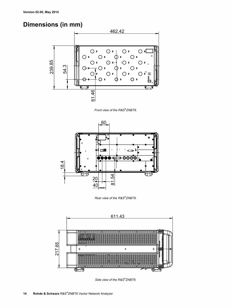
Dimensions (in mm)
Front view of the R&S®ZNBT8.
Rear view of the R&S®ZNBT8.
Side view of the R&S®ZNBT8.
Version 02.00, May 2014
Rohde & Schwarz R&S®ZNBT8 Vector Network Analyzer 15
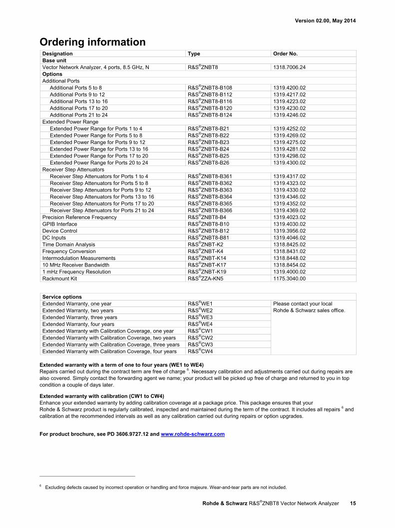
Ordering information Designation Type Order No. Base unit Vector Network Analyzer, 4 ports, 8.5 GHz, N R&S®ZNBT8 1318.7006.24 Options Additional Ports
Additional Ports 5 to 8 R&S®ZNBT8-B108 1319.4200.02 Additional Ports 9 to 12 R&S®ZNBT8-B112 1319.4217.02 Additional Ports 13 to 16 R&S®ZNBT8-B116 1319.4223.02 Additional Ports 17 to 20 R&S®ZNBT8-B120 1319.4230.02 Additional Ports 21 to 24 R&S®ZNBT8-B124 1319.4246.02
Extended Power Range Extended Power Range for Ports 1 to 4 R&S®ZNBT8-B21 1319.4252.02 Extended Power Range for Ports 5 to 8 R&S®ZNBT8-B22 1319.4269.02 Extended Power Range for Ports 9 to 12 R&S®ZNBT8-B23 1319.4275.02 Extended Power Range for Ports 13 to 16 R&S®ZNBT8-B24 1319.4281.02 Extended Power Range for Ports 17 to 20 R&S®ZNBT8-B25 1319.4298.02 Extended Power Range for Ports 20 to 24 R&S®ZNBT8-B26 1319.4300.02
Receiver Step Attenuators Receiver Step Attenuators for Ports 1 to 4 R&S®ZNBT8-B361 1319.4317.02 Receiver Step Attenuators for Ports 5 to 8 R&S®ZNBT8-B362 1319.4323.02 Receiver Step Attenuators for Ports 9 to 12 R&S®ZNBT8-B363 1319.4330.02 Receiver Step Attenuators for Ports 13 to 16 R&S®ZNBT8-B364 1319.4346.02 Receiver Step Attenuators for Ports 17 to 20 R&S®ZNBT8-B365 1319.4352.02 Receiver Step Attenuators for Ports 21 to 24 R&S®ZNBT8-B366 1319.4369.02
Precision Reference Frequency R&S®ZNBT8-B4 1319.4023.02 GPIB Interface R&S®ZNBT8-B10 1319.4030.02 Device Control R&S®ZNBT8-B12 1319.3956.02 DC Inputs R&S®ZNBT8-B81 1319.4046.02 Time Domain Analysis R&S®ZNBT-K2 1318.8425.02 Frequency Conversion R&S®ZNBT-K4 1318.8431.02 Intermodulation Measurements R&S®ZNBT-K14 1318.8448.02 10 MHz Receiver Bandwidth R&S®ZNBT-K17 1318.8454.02 1 mHz Frequency Resolution R&S®ZNBT-K19 1319.4000.02 Rackmount Kit R&S®ZZA-KN5 1175.3040.00
Service options Extended Warranty, one year R&S®WE1 Please contact your local
Rohde & Schwarz sales office.
Extended Warranty, two years R&S®WE2 Extended Warranty, three years R&S®WE3 Extended Warranty, four years R&S®WE4 Extended Warranty with Calibration Coverage, one year R&S®CW1 Extended Warranty with Calibration Coverage, two years R&S®CW2 Extended Warranty with Calibration Coverage, three years R&S®CW3 Extended Warranty with Calibration Coverage, four years R&S®CW4
Extended warranty with a term of one to four years (WE1 to WE4) Repairs carried out during the contract term are free of charge 6. Necessary calibration and adjustments carried out during repairs are also covered. Simply contact the forwarding agent we name; your product will be picked up free of charge and returned to you in top condition a couple of days later.
Extended warranty with calibration (CW1 to CW4) Enhance your extended warranty by adding calibration coverage at a package price. This package ensures that your Rohde & Schwarz product is regularly calibrated, inspected and maintained during the term of the contract. It includes all repairs 6 and calibration at the recommended intervals as well as any calibration carried out during repairs or option upgrades.
For product brochure, see PD 3606.9727.12 and www.rohde-schwarz.com
6 Excluding defects caused by incorrect operation or handling and force majeure. Wear-and-tear parts are not included.
Service that adds value Worldwide Local and personalized Customized and flexible Uncompromising quality Long-term dependability
About Rohde & SchwarzThe Rohde & Schwarz electronics group is a leading supplier of solutions in the fields of test and measurement, broadcasting, secure communications, and radiomonitoring and radiolocation. Founded more than 80 years ago, this independent global company has an extensive sales network and is present in more than 70 countries. The company is headquartered in Munich, Germany.
Regional contact Europe, Africa, Middle East | +49 89 4129 12345 customersupport@rohdeschwarz.com
North America | 1 888 TEST RSA (1 888 837 87 72) [email protected]schwarz.com
Latin America | +1 410 910 79 88 customersupport.la@rohdeschwarz.com
Asia/Pacific | +65 65 13 04 88 customersupport.asia@rohdeschwarz.com
China | +86 800 810 8228/+86 400 650 5896 customersupport.china@rohdeschwarz.com
Rohde & Schwarz GmbH & Co. KGwww.rohdeschwarz.com
Sustainable product design Environmental compatibility and ecofootprint Energy efficiency and low emissions Longevity and optimized total cost of ownership
Certified Environmental Management
ISO 14001Certified Quality Management
ISO 9001
R&S® is a registered trademark of Rohde & Schwarz GmbH & Co. KG
Trade names are trademarks of the owners
PD 3606.9727.22 | Version 02.00 | May 2014 (ch)
R&S®ZNBT8 Vector Network Analyzer
Data without tolerance limits is not binding | Subject to change
© 2014 Rohde & Schwarz GmbH & Co. KG | 81671 Munich, Germany 3606
.972
7.22
02.
00 P
DP
1 e
n
3606972722
ZNBT8_dat-sw_en_3606-9727-22_v0200_cover.indd 2 20.05.2014 08:39:42


![INDEX [housewares.blob.core.windows.net] · 1524-EMERALD-GREEN 1524-LIGHT-GREEN 1525-BERBER 1525-BLACK-BROWN 1525-BROWN 1525-BURGUNDY 1525-EMERALD-GREEN 1525-LIGHT-GREEN 1526-BROWN](https://static.fdocuments.net/doc/165x107/5f82d2e19f012e44495be61c/index-1524-emerald-green-1524-light-green-1525-berber-1525-black-brown-1525-brown.jpg)