
RSPile - Driven Theory Manual
16
RSPile - Driven Theory Manual Rocscience Inc. 2015
Transcript of RSPile - Driven Theory Manual

RSPile - Driven Theory Manual
Rocscience Inc. 2015
Bearing Capacity of Driven Piles 1
Table of Contents
1 Introduction ............................................................................................................................. 4
1.1 Calculated Capacities ....................................................................................................... 4
1.2 Special Design Considerations ......................................................................................... 4
1.2.1 Scour ......................................................................................................................... 4
1.2.2 Soft Compressible Soils / Negative Skin Friction .................................................... 4
1.3 Ultimate Vertical Load Capacity...................................................................................... 5
2 Capacity Calculations ............................................................................................................. 6
2.1 Sand Layers ...................................................................................................................... 6
2.1.1 Shaft Resistance ........................................................................................................ 6
2.1.1.1 𝜔, Pile Taper Angle ........................................................................................... 7
2.1.1.2 𝐾𝛿, Coefficient of Lateral Stress ....................................................................... 7
2.1.1.3 𝛿, Pile-Soil Interface Friction Angle ............................................................... 10
2.1.1.4 𝐶𝑓, Correction factor for 𝐾𝛿 ........................................................................... 10
2.1.2 End Bearing Capacity ............................................................................................. 11
2.1.2.1 𝛼, Modification Factor ..................................................................................... 11
2.1.2.2 𝑁𝑞′, Bearing Capacity Factor .......................................................................... 12
2.1.2.3 𝑞𝐿, Limiting Unit Pile Toe Resistance ............................................................ 12
2.2 Clay Layers .................................................................................................................... 13
2.2.1 Shaft Resistance ...................................................................................................... 13
2.2.1.1 𝑓𝑠, Unit Shaft Capacity for Cohesive Soils ..................................................... 13
2.2.2 End Bearing Capacity ............................................................................................. 14
2.3 Driving Capacity ............................................................................................................ 15
2.4 Plugging ......................................................................................................................... 15
Bearing Capacity of Driven Piles 2
Symbols
𝐾𝛿 coefficient of lateral earth pressure at depth 𝑧
𝐶𝑓 correction factor for 𝐾𝛿 when 𝛿 ≠ 0
𝑝𝑑 effective overburden pressure at midpoint of layer
𝛿 pile-soil interface friction angle
𝜔 pile taper angle
𝑑𝑡𝑜𝑝 diameter of the top of the pile
𝑑𝑏𝑜𝑡 diameter of the bottom of the pile
𝐿 length of pile taper
𝑑𝑈𝐵 diameter at the upper layer
𝑑𝐿𝐵 diameter of the lower part of the shaft-soil contact surface
𝑢 unit length of the pile
𝐴𝑝 cross-sectional area of the pile
𝑞𝑝 bearing capacity at pile tip
�̅� effective overburden pressure at pile toe
𝛼𝑡 coefficient based on pile geometry
𝑁𝑞′ bearing capacity factor
𝑓𝑠 unit shaft friction
𝐴𝑡 pile area at pile toe bearing
𝑐𝑎 adhesion value based on Tomlinson’s charts
𝛼 adhesion factor based on Tomlinson’s charts
𝑐𝑢 undrained shear strength
𝐴𝑡 pile area at pile toe bearing
𝑐𝑢 undrained shear strength
𝑁𝑐 dimensionless parameter (typically 𝑁𝑐 = 9)
𝑄𝑢,𝑑𝑟𝑖𝑣𝑖𝑛𝑔 driving total capacity
𝑄𝑠,𝑟𝑒𝑠𝑡𝑟𝑖𝑘𝑒 restrike shaft capacity
%𝐷𝐿 percent driving strength losses
𝑄𝑝 pile toe capacity
Bearing Capacity of Driven Piles 3
Figures
Figure 1: Design curves for evaluating Kδ for piles when ϕ = 25°
Figure 2: Design curves for evaluating Kδ for piles when ϕ = 30°
Figure 3: Design curves for evaluating Kδ for piles when ϕ = 35°
Figure 4: Design curves for evaluating Kδ for piles when ϕ = 40°
Figure 5: δ/ϕ relationship with pile type and volume
Figure 6: Correction factor for Kδ when δ ≠ 0
Figure 7: α coefficient for pile toe resistance
Figure 8: Bearing capacity factor for pile toe resistance
Figure 9: Limit factor on toe resistance
Figure 10: General Pile Shaft Adhesion Values
Figure 11: Special Shaft α Adhesion Factors

Bearing Capacity of Driven Piles 4
1 Introduction
The purpose of this manual is to describe in detail the FHWA method of axial pile capacity
calculation used by DRIVEN, which is implemented in the driven pile section of RSPile.
1.1 Calculated Capacities
The following capacities are calculated by the program:
Restrike – computes static skin and end bearing resistance for the entire soil profile. Restrike
computations do not consider the effects of soft soils or scour conditions.
Driving – The user may enter a loss of soil strength in the soil profile for each soil layer due to
the effects of driving. The driving computations are based upon the restrike calculations minus
the soil strength loss due to driving.
Ultimate – Ultimate capacity computations consider the effects of soft soil conditions or scour.
This is the ultimate capacity available to resist applied loads.
1.2 Special Design Considerations
The following design considerations are mutually exclusive. They cannot both be used at the
same time.
1.2.1 Scour
There are two types of scour that can be considered: long-term and short-term (local) scour. For
short-term scour, the shear stress is simply reduced to zero. This occurs due to erosion around the
pile. The effective overburden pressure 𝜎𝑣′ is not affected due to the presence of soil away from
the local pile area. No end bearing can be placed above this level.
For long-term scour, the effective overburden stress is reduced to zero until the scour
consideration depth. This is due to soil eroding over a large area, reducing the effective
overburden stress. DRIVEN stacks the effects of both scour types, where long-term scour is first
considered then local scour is applied below the long-term scour depth.
1.2.2 Soft Compressible Soils / Negative Skin Friction
A depth of soft compressible soil at the top of the soil profile can be specified. For ultimate
calculations, the shaft resistance from the soft soil layer can be considered as soft compressible
soil or as negative skin friction.
Bearing Capacity of Driven Piles 5
If the shaft resistance is considered to be soft soil, the skin friction for the layer is not included in
the ultimate skin friction capacity. If negative skin friction is considered, the skin friction from
the soft soil layer is considered to be negative and is subtracted from the total skin friction for
ultimate capacity computations.
1.3 Ultimate Vertical Load Capacity
The load-carrying capacity of a single pile comes from the frictional resistance of the soil around
the shaft and bearing capacity at the pile tip:
𝑄 = 𝑄𝑝 + 𝑄𝑠
where,
𝑄𝑝 = 𝐴𝑝 ∗ 𝑞𝑝
and
𝑄𝑠 = ∫ 𝑓𝑠𝐶𝑑𝑑𝑧𝐿
0
in which:
𝐴𝑝 = area of pile tip
𝑞𝑝 = bearing capacity at pile tip
𝑓𝑠 = ultimate skin resistance per unit area of shaft
𝐶𝑑 = effective perimeter of pile
𝐿 = length of pile in contact with soil
𝑧 = depth
The main requirement for design is to estimate the magnitude of 𝑓𝑠 with depth for friction piles
and 𝑞𝑝 for end bearing piles.

Bearing Capacity of Driven Piles 6
2 Capacity Calculations
2.1 Sand Layers
2.1.1 Shaft Resistance
Nordlund (1963,1979) suggests the following equation for calculating the ultimate skin
resistance per unit area:
𝑓𝑠 = 𝐾𝛿𝐶𝑓𝑝𝑑
sin(𝛿 + 𝜔)
cos 𝜔
where,
𝐾𝛿 = coefficient of lateral earth pressure at depth 𝑧
𝐶𝑓 = correction factor for 𝐾𝛿 when 𝛿 ≠ 0
𝑝𝑑 = effective overburden pressure at midpoint of layer
𝛿 = pile-soil interface friction angle
𝜔 = pile taper angle
Based on the Nordlund equation, the frictional resistance of the soil around the pile shaft is
calculated as:
𝑄𝑠 = ∫ 𝐾𝛿𝐶𝑓𝑝𝑑
sin(𝜔 + 𝛿)
cos(𝜔)𝐶𝑑𝑑𝑧
𝐿
0
= ∑ 𝐾𝛼𝑖𝐶𝑓𝑖𝑝𝑑𝑖
sin(𝜔 + 𝛿)
cos(𝜔)𝐶𝑑𝑖𝐷𝑖
𝑛
𝑖=1
where
𝐶𝑑 = effective pile perimeter.
Bearing Capacity of Driven Piles 7
2.1.1.1 𝜔, Pile Taper Angle
If the pile is not-tapered, 𝜔 = 0. For tapered piles, the pile taper angle is calculated as shown
below:
𝜔 = tan−1𝑑𝑡𝑜𝑝 − 𝑑𝑏𝑜𝑡
2𝐿
where,
𝑑𝑡𝑜𝑝 = diameter of the top of the pile
𝑑𝑏𝑜𝑡 = diameter of the bottom of the pile
𝐿 = length of pile taper
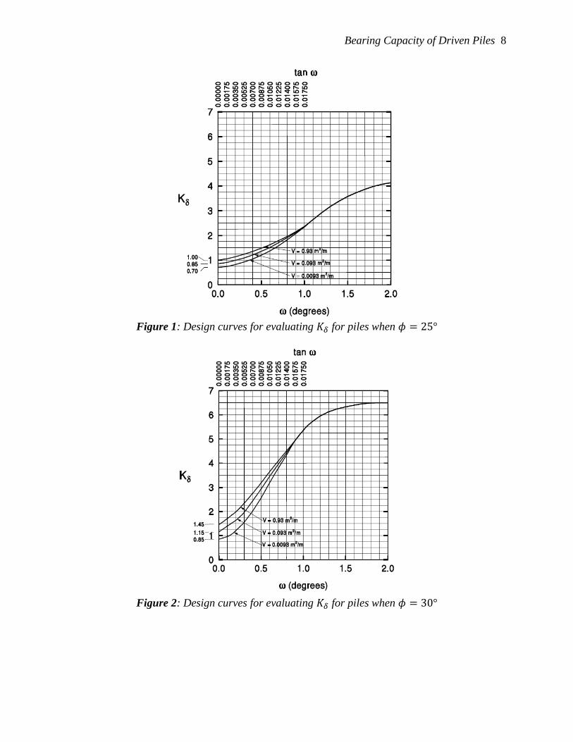
2.1.1.2 𝐾𝛿, Coefficient of Lateral Stress
The coefficient of lateral stress is calculated from the figures below.
The volume displacement rate is the volume of soil displaced per unit length of pile (e.g. m3/m).
For uniform piles:
𝑉 = 𝐴𝑝
where
𝐴𝑝 = cross-sectional area of the pile.
For circular tapered piles, the volume is determined from the average diameter within the layer in
question:
𝑉 = 𝜋 (
𝑑𝑈𝐵
2 +𝑑𝐿𝐵
22
)
2
𝑢
where
𝑑𝑈𝐵 = diameter at the upper layer
𝑑𝐿𝐵 = diameter of the lower part of the shaft-soil contact surface
𝑢 = unit length of the pile
Bearing Capacity of Driven Piles 8
Figure 1: Design curves for evaluating 𝐾𝛿 for piles when 𝜙 = 25°
Figure 2: Design curves for evaluating 𝐾𝛿 for piles when 𝜙 = 30°
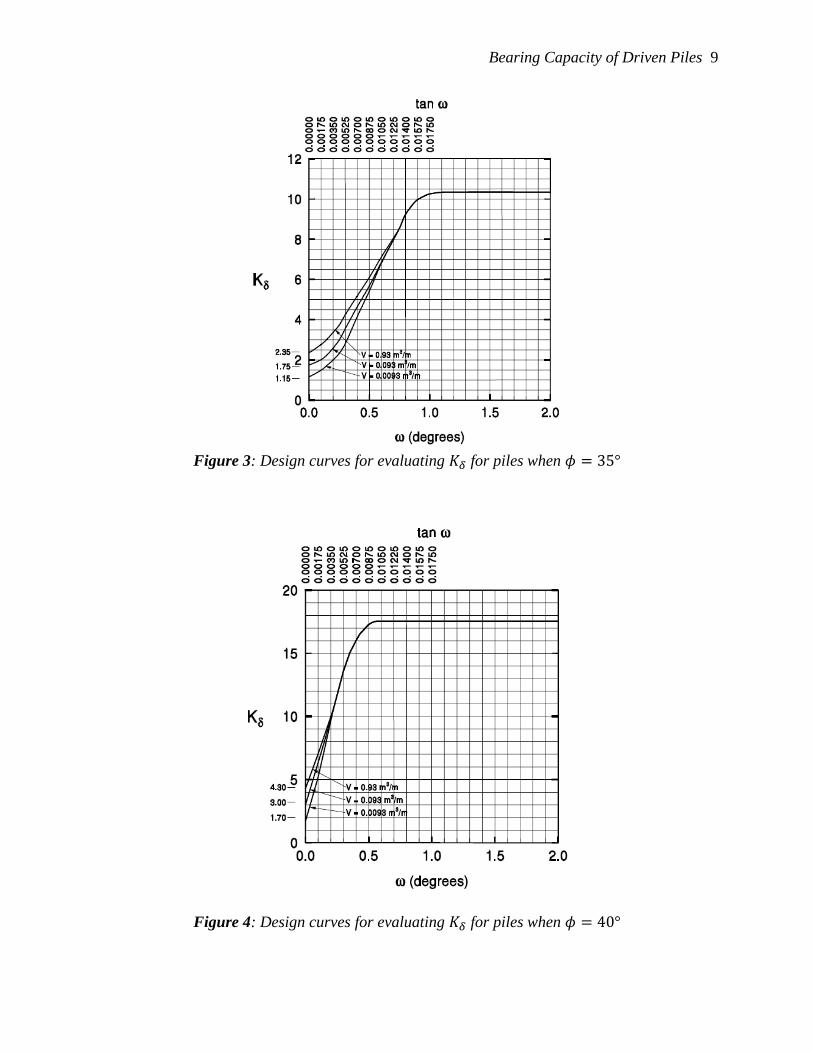
Bearing Capacity of Driven Piles 9
Figure 3: Design curves for evaluating 𝐾𝛿 for piles when 𝜙 = 35°
Figure 4: Design curves for evaluating 𝐾𝛿 for piles when 𝜙 = 40°

Bearing Capacity of Driven Piles 10
2.1.1.3 𝛿, Pile-Soil Interface Friction Angle
The pile-soil interface friction angle is determined using the figure below.
Figure 5: 𝛿/𝜙 relationship with pile type and volume
2.1.1.4 𝐶𝑓, Correction factor for 𝐾𝛿
Figure 6: Correction factor for 𝐾𝛿 when 𝛿 ≠ 0
Bearing Capacity of Driven Piles 11
2.1.2 End Bearing Capacity
The calculation of the end bearing capacity also requires obtaining values from graphs. A
limiting value for end bearing capacity is also obtained graphically.
𝑄𝑝 = 𝐴𝑝𝑞𝑝
where
𝐴𝑝 = area of pile tip for bearing
𝑞𝑝 = bearing capacity at pile tip
The bearing capacity at the pile tip is calculated as:
𝑞𝑝 = �̅�𝛼𝑡𝑁𝑞′ ≤ 𝑞𝐿
where
�̅� = effective overburden pressure at pile toe
𝛼𝑡 = coefficient based on pile geometry
𝑁𝑞′ = bearing capacity factor
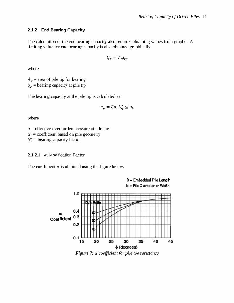
2.1.2.1 𝛼, Modification Factor
The coefficient 𝛼 is obtained using the figure below.
Figure 7: 𝛼 coefficient for pile toe resistance

Bearing Capacity of Driven Piles 12
2.1.2.2 𝑁𝑞′ , Bearing Capacity Factor
The bearing capacity factor for pile toe resistance is obtained using the figure below.
Figure 8: Bearing capacity factor for pile toe resistance
2.1.2.3 𝑞𝐿, Limiting Unit Pile Toe Resistance
The limiting toe resistance is obtained using the figure below.
Figure 9: Limit factor on toe resistance

Bearing Capacity of Driven Piles 13
2.2 Clay Layers
2.2.1 Shaft Resistance
The FHWA recommends the 𝛼 method for clays. To calculate 𝛼, a factor multiplied with
undrained shear strength, Tomlinson’s graphs are used. Tomlinson also supplies a general
adhesion value as a function of normalized pile depth and undrained shear strength.
The shaft capacity for cohesive soils is:
𝑄𝑠 = 𝑓𝑠𝐴𝑡
where
𝑓𝑠 = unit shaft friction
𝐴𝑡 = pile area at pile toe bearing.
2.2.1.1 𝑓𝑠, Unit Shaft Capacity for Cohesive Soils
The unit shaft capacity is calculated as:
𝑓𝑠 = 𝑐𝑎 = 𝛼𝑐𝑢
where
𝑐𝑎 = adhesion value based on Tomlinson’s charts
𝛼 = adhesion factor based on Tomlinson’s charts
𝑐𝑢 = undrained shear strength
The adhesion values, 𝑐𝑎, and adhesion factor, 𝑐𝑢, are determined from the two figures below.
Figure 10: General Pile Shaft Adhesion Values

Bearing Capacity of Driven Piles 14
Figure 11: Special Shaft α Adhesion Factors
2.2.2 End Bearing Capacity
The toe capacity for cohesive soils is
𝑄𝑝 = 𝐴𝑡𝑐𝑢𝑁𝑐
where
𝐴𝑡 = pile area at pile toe bearing
𝑐𝑢 = undrained shear strength
𝑁𝑐 = dimensionless parameter (typically 𝑁𝑐 = 9).
Bearing Capacity of Driven Piles 15
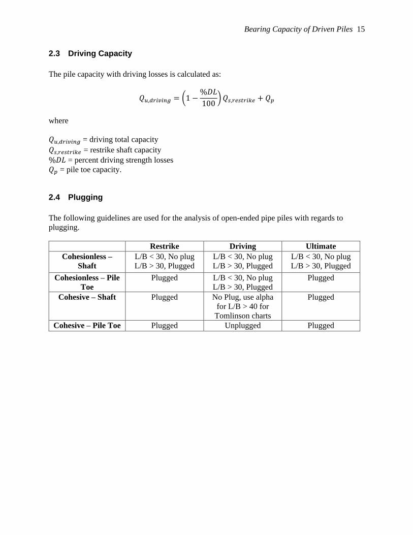
2.3 Driving Capacity
The pile capacity with driving losses is calculated as:
𝑄𝑢,𝑑𝑟𝑖𝑣𝑖𝑛𝑔 = (1 −%𝐷𝐿
100) 𝑄𝑠,𝑟𝑒𝑠𝑡𝑟𝑖𝑘𝑒 + 𝑄𝑝
where
𝑄𝑢,𝑑𝑟𝑖𝑣𝑖𝑛𝑔 = driving total capacity
𝑄𝑠,𝑟𝑒𝑠𝑡𝑟𝑖𝑘𝑒 = restrike shaft capacity
%𝐷𝐿 = percent driving strength losses
𝑄𝑝 = pile toe capacity.
2.4 Plugging
The following guidelines are used for the analysis of open-ended pipe piles with regards to
plugging.
Restrike Driving Ultimate
Cohesionless –
Shaft
L/B < 30, No plug
L/B > 30, Plugged
L/B < 30, No plug
L/B > 30, Plugged
L/B < 30, No plug
L/B > 30, Plugged
Cohesionless – Pile
Toe
Plugged L/B < 30, No plug
L/B > 30, Plugged
Plugged
Cohesive – Shaft Plugged No Plug, use alpha
for L/B > 40 for
Tomlinson charts
Plugged
Cohesive – Pile Toe Plugged Unplugged Plugged


![Data-Driven Decision Theory for Player Analysis in Pacman€¦ · Data-Driven Decision Theory for Player Analysis in Pacman ... and game studies researchers [Salen & Zimmerman 2003].](https://static.fdocuments.net/doc/165x107/5b0e72297f8b9af9688bfe18/data-driven-decision-theory-for-player-analysis-in-pacman-decision-theory-for-player.jpg)
