R&S CMW GSM User Manual - vogold.com.cn · This user manual describes the following R&S®CMW...
486
R&S ® CMW-KG2xx/-KM2xx/-KS2xx GSM Firmware Applications User Manual User Manual (;×îR2) 1173.9634.02 ─ 06 Test & Measurement
Transcript of R&S CMW GSM User Manual - vogold.com.cn · This user manual describes the following R&S®CMW...
R&S®CMW-KG2xx/-KM2xx/-KS2xxGSM Firmware ApplicationsUser Manual
User
Man
ual
(;×îR2)1173.9634.02 ─ 06
Test
& Me
asur
emen
t
This user manual describes the following R&S®CMW options:
● R&S®CMW-KG200 (GSM GPRS EDGE R6, generator, downlink)
● R&S®CMW-KM200 (GSM GPRS EDGE R6, TX measurement, uplink)
● R&S®CMW-KM201 (GSM R7 EGRPS2-A, TX measurement, uplink)
● R&S®CMW-KM012 (TX measurement, multi evaluation list mode for GSM)
● R&S®CMW-KS200 (GSM GPRS EDGE R6, basic signaling)
● R&S®CMW-KS201 (GSM R7 EDGEevo, basic signaling)
● R&S®CMW-KS203 (GSM R9 VAMOS, basic signaling)
● R&S®CMW-KS210 (GSM GPRS EDGE R6, advanced signaling)
● R&S®CMW-KE100 (Basic Fading support: AWGN generator)
● R&S®CMW-KE200 (GSM fading profiles TS 45.005, excerpts)
© 2012 Rohde & Schwarz GmbH & Co. KGMuehldorfstr. 15, 81671 Munich, GermanyPhone: +49 89 41 29 - 0Fax: +49 89 41 29 12 164E-mail: [email protected]: http://www.rohde-schwarz.comSubject to change – Data without tolerance limits is not binding.R&S® is a registered trademark of Rohde & Schwarz GmbH & Co. KG.Trade names are trademarks of the owners.
The following abbreviations are used throughout this manual: R&S®CMW is abbreviated as R&S CMW.
ContentsR&S®CMW-KG2xx/-KM2xx/-KS2xx
3User Manual 1173.9634.02 ─ 06
Contents1 Preface....................................................................................................7
1.1 How to Read Firmware Application Chapters............................................................7
1.1.1 General Description........................................................................................................7
1.1.2 Application Sheets..........................................................................................................7
1.1.3 GUI Reference................................................................................................................8
1.1.4 Programming Examples..................................................................................................8
1.1.5 Command Reference......................................................................................................8
2 GSM Generator.......................................................................................92.1 What's New in this Revision.........................................................................................9
2.2 General Description......................................................................................................9
2.2.1 GSM Signal Parameters...............................................................................................10
2.2.2 GSM Frequency Bands and Channels..........................................................................10
2.2.3 Burst Types...................................................................................................................11
2.2.4 Training Sequences......................................................................................................13
2.2.5 Power Control Levels....................................................................................................15
2.2.6 BCCH and TCH Bursts.................................................................................................16
2.2.7 Dynamic Aspects..........................................................................................................17
2.3 Application Sheets......................................................................................................18
2.3.1 Generating and Measuring a GSM Signal....................................................................18
2.3.2 GSM BER Tests on Real-Time Signals........................................................................22
2.4 GUI Reference.............................................................................................................24
2.4.1 Generator Control.........................................................................................................24
2.4.2 Signal Routing and RF Settings....................................................................................24
2.4.3 Slot Configuration..........................................................................................................26
2.5 Programming...............................................................................................................29
2.5.1 Key Features.................................................................................................................29
2.5.2 Specifying General and RF Settings.............................................................................29
2.5.3 Slot Configuration..........................................................................................................30
2.5.4 Switching on the Generator...........................................................................................30
2.6 Command Reference..................................................................................................31
2.6.1 Generator Control and States.......................................................................................32
ContentsR&S®CMW-KG2xx/-KM2xx/-KS2xx
4User Manual 1173.9634.02 ─ 06
2.6.2 Signal Routing...............................................................................................................32
2.6.3 RF Settings...................................................................................................................34
2.6.4 Slot Configuration..........................................................................................................36
2.7 List of Commands.......................................................................................................39
3 GSM Measurements.............................................................................403.1 What's New in this Revision.......................................................................................40
3.2 General Description....................................................................................................40
3.2.1 GSM TX Tests...............................................................................................................41
3.2.2 GSM RX Tests..............................................................................................................43
3.2.3 List Mode.......................................................................................................................44
3.2.4 GSM UL Signal Properties............................................................................................50
3.2.5 GSM Frequency Bands and Channels..........................................................................51
3.2.6 Burst Types...................................................................................................................52
3.2.7 Limit Settings and Conformance Requirements............................................................53
3.2.8 Measurement Results...................................................................................................65
3.3 Application Sheets......................................................................................................73
3.3.1 Detecting GSM Multislot Frames..................................................................................73
3.3.2 Capturing GSM Burst Sequences.................................................................................75
3.3.3 Using GSM List Mode...................................................................................................78
3.3.4 GSM BER Tests on ARB Signals..................................................................................80
3.4 GUI Reference.............................................................................................................82
3.4.1 Measurement Control....................................................................................................82
3.4.2 Parameters and Settings...............................................................................................83
3.4.3 Measurement Results.................................................................................................107
3.5 Programming.............................................................................................................110
3.5.1 General Examples.......................................................................................................110
3.5.2 GSM List Mode...........................................................................................................114
3.5.3 BER Measurement......................................................................................................118
3.5.4 I/Q Constellation Diagram...........................................................................................118
3.6 Command Reference................................................................................................119
3.6.1 Conventions and General Information........................................................................119
3.6.2 General Measurement Settings..................................................................................122
3.6.3 Multi Evaluation Measurement Commands................................................................128
ContentsR&S®CMW-KG2xx/-KM2xx/-KS2xx
5User Manual 1173.9634.02 ─ 06
3.7 List of Commands.....................................................................................................238
4 GSM Signaling....................................................................................2474.1 What's New in this Revision.....................................................................................247
4.2 General Description..................................................................................................248
4.2.1 Test Setups.................................................................................................................248
4.2.2 Initiating Signaling Tests.............................................................................................252
4.2.3 External Fading...........................................................................................................254
4.2.4 Internal Fading............................................................................................................255
4.2.5 End to End Packet Data Connections.........................................................................256
4.2.6 Connection States.......................................................................................................257
4.2.7 Handover.....................................................................................................................261
4.2.8 Trigger Signals............................................................................................................262
4.2.9 BER CS Measurement................................................................................................263
4.2.10 BER PS Measurement................................................................................................273
4.2.11 BLER Measurement....................................................................................................278
4.2.12 GSM Characteristics...................................................................................................282
4.3 Application Sheets....................................................................................................287
4.3.1 GSM Combined Signal Path Measurements..............................................................287
4.3.2 Handover from WCDMA to GSM................................................................................291
4.4 GUI Reference...........................................................................................................294
4.4.1 Signaling View.............................................................................................................295
4.4.2 Signaling and Connection Control...............................................................................308
4.4.3 General Settings.........................................................................................................311
4.4.4 I/Q Settings.................................................................................................................312
4.4.5 RF Settings.................................................................................................................314
4.4.6 Internal Fading............................................................................................................321
4.4.7 Network Parameters...................................................................................................324
4.4.8 Connection Parameters..............................................................................................332
4.4.9 Trigger Signal Settings................................................................................................343
4.4.10 Messaging (SMS) Parameters....................................................................................343
4.4.11 Measurement Connection Parameters.......................................................................344
4.4.12 Show Features at Inactive SW Licenses.....................................................................345
4.4.13 Using the Shortcut Softkeys........................................................................................345
ContentsR&S®CMW-KG2xx/-KM2xx/-KS2xx
6User Manual 1173.9634.02 ─ 06
4.4.14 BER CS Measurement................................................................................................346
4.4.15 BER PS Measurement................................................................................................350
4.4.16 BLER Measurement....................................................................................................354
4.5 Programming.............................................................................................................356
4.5.1 Signaling Application...................................................................................................356
4.5.2 BER CS Measurements..............................................................................................370
4.5.3 BER PS Measurement................................................................................................373
4.5.4 BLER Measurement....................................................................................................374
4.6 Command Reference................................................................................................374
4.6.1 Conventions and General Information........................................................................375
4.6.2 General Settings.........................................................................................................378
4.6.3 Connection Control and States...................................................................................378
4.6.4 Event Log....................................................................................................................382
4.6.5 Signaling Information..................................................................................................383
4.6.6 Slot Configuration and Resulting Throughput.............................................................399
4.6.7 Handover.....................................................................................................................404
4.6.8 Routing Settings..........................................................................................................409
4.6.9 Internal Fading............................................................................................................425
4.6.10 Network Settings.........................................................................................................430
4.6.11 Connection Settings....................................................................................................442
4.6.12 Trigger Signal Settings................................................................................................458
4.6.13 Messaging (SMS)........................................................................................................459
4.6.14 Measurement Slot Settings.........................................................................................461
4.6.15 BER CS Measurement................................................................................................461
4.6.16 BER PS Measurement................................................................................................468
4.6.17 BLER Measurement....................................................................................................473
4.7 List of Commands.....................................................................................................478
Index....................................................................................................484

PrefaceR&S®CMW-KG2xx/-KM2xx/-KS2xx
7User Manual 1173.9634.02 ─ 06
1 PrefaceThe operation of the R&S CMW is described in several user manuals:● The R&S CMW user manual describes the base software, common features of the
firmware applications and basic principles for manual operation and remote control.● Additional user manuals, like this document, describe the firmware applications.
Rohde & Schwarz provides registered users a "CMW Customer Web" section onGLORIS, the Global Rohde & Schwarz Information System: https://extranet.rohde-schwarz.com. From this resource you can download software updates, waveform libraryupdates and documentation updates, e.g. updates of this document.
1.1 How to Read Firmware Application Chapters
Each firmware application is described in a separate chapter. These chapters can beread independently of each other. However, they are all organized as follows:
1. General Description
2. Application Sheets (optional)
3. GUI Reference
4. Programming Examples
5. Command Reference
The chapters "System Overview" and "Remote Control" in the R&S CMW user manualprovide additional important information independent of the individual firmware applica-tions. The most important parts are referenced by the firmware application descriptions.
1.1.1 General Description
This section provides a general description of the firmware application, independent of aspecific operation mode (manual or remote control). It gives a high-level introduction tothe capabilities of the firmware application. Background information related to the networkstandard is given as far as it is directly related to administrable parameters. For mea-surement applications a detailed description of measurement results and a descriptionof configurable limits is given, including the relation to conformance requirements definedin network standard specifications.
1.1.2 Application Sheets
This optional section provides short application examples for select issues and relatedbackground information.
How to Read Firmware Application Chapters
PrefaceR&S®CMW-KG2xx/-KM2xx/-KS2xx
8User Manual 1173.9634.02 ─ 06
1.1.3 GUI Reference
The GUI reference describes the manual operation of the firmware application via theGraphical User Interface (GUI).
The description of a configuration dialog usually starts with a screenshot presenting thepreset values of the parameters (sometimes preset values are modified to enable hiddenparts of a dialog). Below the screenshot all shown parameters are described. For eachsingle parameter a link to the corresponding command description in the "CommandReference" is provided. Ranges for numeric parameters and reset values are given there.
For measurement results links to the corresponding command descriptions are provided(commands to retrieve the results). The measurement results are described in detail inthe "General Description".
1.1.4 Programming Examples
The programming examples show how to control and configure the firmware applicationvia a remote-control program and how to retrieve measurement results. The examplesconsist of comprehensive command sequences. You can check just a single commandof a sequence to get an example for the syntax of this single command. But you can alsoconsider an entire sequence showing the commands in the context of a command script,under consideration of dependencies and required orders of the commands.
The command sequences are written with the intention to list most commands of thefirmware application. They do not show the fastest way for a given configuration task.The fastest way would use many reset values and omit the corresponding commands.
The examples are referenced by the command descriptions of the "Command Refer-ence".
1.1.5 Command Reference
The command reference provides information on the remote commands of the firmwareapplication. The commands are grouped according to their function.
Each command description indicates the syntax of the command header and of theparameters. For input parameters the allowed ranges, reset values and default units arelisted, for returned values the expected ranges and default units. Most commands havea command form and a query form. Exceptions are marked by "Setting only", "Query only"or "Event". Furthermore a link to the "Programming Examples" is provided and the firstsoftware version supporting the command is indicated.
How to Read Firmware Application Chapters
GSM GeneratorR&S®CMW-KG2xx/-KM2xx/-KS2xx
9User Manual 1173.9634.02 ─ 06
2 GSM GeneratorThe GSM generator (option R&S CMW-KG200) provides a flexible GSM downlink testsignal. Refer to the following sections for a detailed description of the generator includingmanual and remote operation.
● What's New in this Revision......................................................................................9● General Description..................................................................................................9● Application Sheets..................................................................................................18● GUI Reference........................................................................................................24● Programming...........................................................................................................29● Command Reference..............................................................................................31● List of Commands...................................................................................................39
2.1 What's New in this Revision
This revision describes version 2.0.10 and later of the "GSM Generator" firmware appli-cation. Compared to previous software versions it provides the following new features:● RF Routing: command ROUTe:GSM:GEN<i>:RFSettings:CONNector no longer
supported; substituted by ROUTe: GSM: GEN<i>: SCENario: SALone on page 32.New command ROUTe: GSM: GEN<i>? .
Software VersionTo check your R&S CMW software version, open the "Setup" dialog and click "HW/SWEquipment". The initial software version for each remote control command is quoted inthe reference description.
2.2 General Description
The GSM generator provides a flexible GSM test signal at arbitrary RF carrier frequency(in-band or out of band) and selectable level. The signal is either frame-periodic or hasa GSM multiframe structure. Each of the 8 timeslots of the TDMA frame may contain aburst of a particular type.
The data fields of the configurable burst types can be filled with periodic or pseudo-ran-dom bit sequences. The data may be transmitted with or without channel coding. Withthese properties the GSM generator signal is well suited for layer 1 and RF tests and forBit Error Rate (BER) measurements.
The following sections provide more detailed information about the properties of the GSMsignal.
● GSM Signal Parameters.........................................................................................10● GSM Frequency Bands and Channels....................................................................10● Burst Types.............................................................................................................11
What's New in this Revision
GSM GeneratorR&S®CMW-KG2xx/-KM2xx/-KS2xx
10User Manual 1173.9634.02 ─ 06
● Training Sequences................................................................................................13● Power Control Levels..............................................................................................15● BCCH and TCH Bursts...........................................................................................16● Dynamic Aspects....................................................................................................17
2.2.1 GSM Signal Parameters
The GSM physical channel uses a combination of frequency and time division multiplex-ing and is defined as a sequence of radio frequency channels and timeslots. The basicsystem and physical channel parameters are listed below.
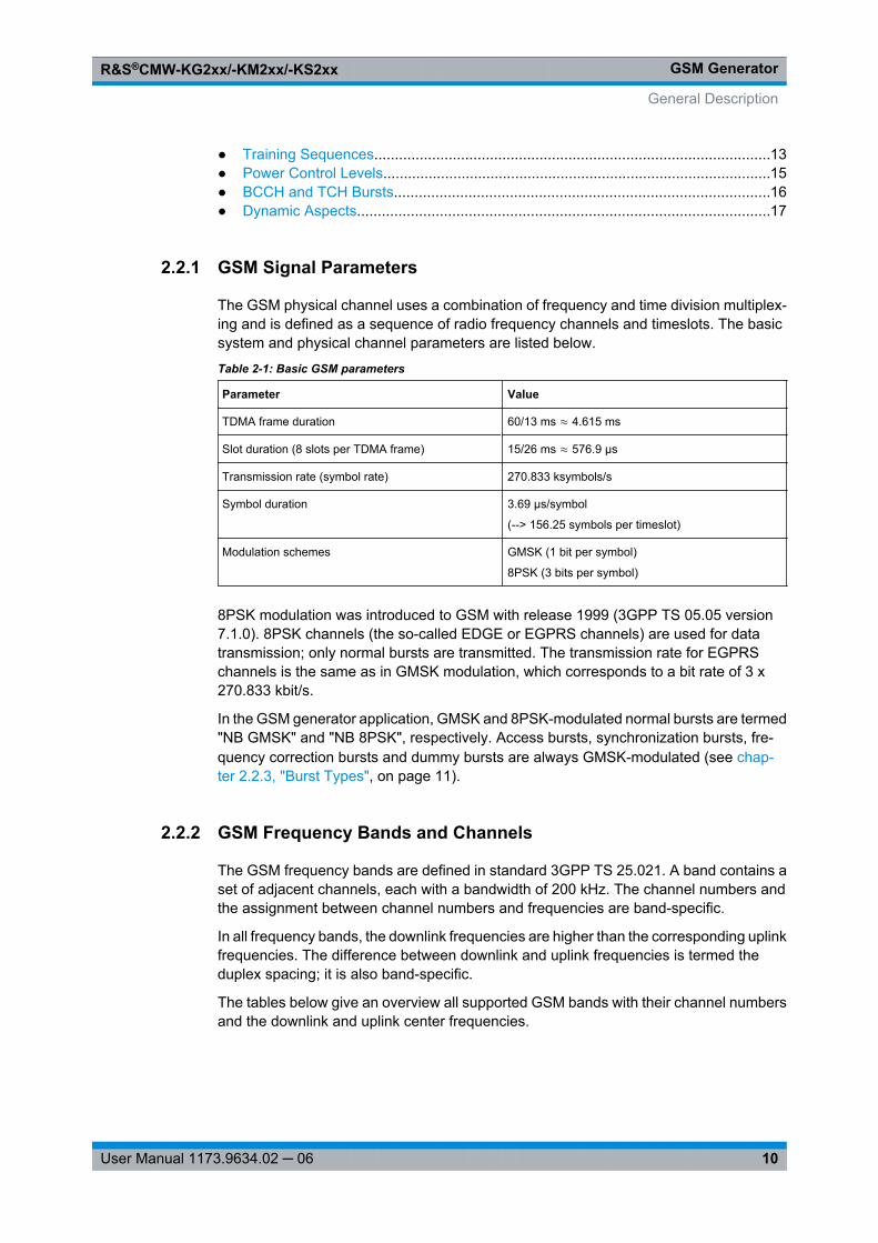
Table 2-1: Basic GSM parameters
Parameter Value
TDMA frame duration 60/13 ms ≈ 4.615 ms
Slot duration (8 slots per TDMA frame) 15/26 ms ≈ 576.9 μs
Transmission rate (symbol rate) 270.833 ksymbols/s
Symbol duration 3.69 μs/symbol
(--> 156.25 symbols per timeslot)
Modulation schemes GMSK (1 bit per symbol)
8PSK (3 bits per symbol)
8PSK modulation was introduced to GSM with release 1999 (3GPP TS 05.05 version7.1.0). 8PSK channels (the so-called EDGE or EGPRS channels) are used for datatransmission; only normal bursts are transmitted. The transmission rate for EGPRSchannels is the same as in GMSK modulation, which corresponds to a bit rate of 3 x270.833 kbit/s.
In the GSM generator application, GMSK and 8PSK-modulated normal bursts are termed"NB GMSK" and "NB 8PSK", respectively. Access bursts, synchronization bursts, fre-quency correction bursts and dummy bursts are always GMSK-modulated (see chap-ter 2.2.3, "Burst Types", on page 11).
2.2.2 GSM Frequency Bands and Channels
The GSM frequency bands are defined in standard 3GPP TS 25.021. A band contains aset of adjacent channels, each with a bandwidth of 200 kHz. The channel numbers andthe assignment between channel numbers and frequencies are band-specific.
In all frequency bands, the downlink frequencies are higher than the corresponding uplinkfrequencies. The difference between downlink and uplink frequencies is termed theduplex spacing; it is also band-specific.
The tables below give an overview all supported GSM bands with their channel numbersand the downlink and uplink center frequencies.
General Description
GSM GeneratorR&S®CMW-KG2xx/-KM2xx/-KS2xx
11User Manual 1173.9634.02 ─ 06
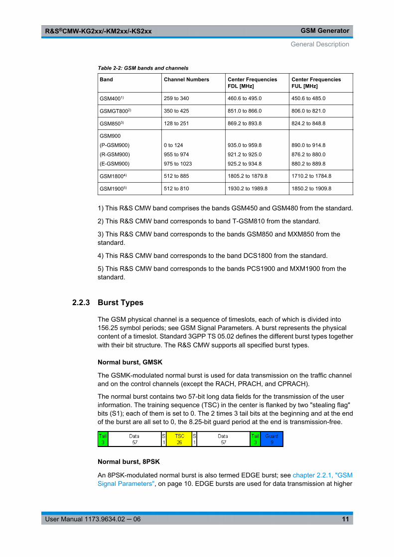
Table 2-2: GSM bands and channels
Band Channel Numbers Center FrequenciesFDL [MHz]
Center FrequenciesFUL [MHz]
GSM4001) 259 to 340 460.6 to 495.0 450.6 to 485.0
GSMGT8002) 350 to 425 851.0 to 866.0 806.0 to 821.0
GSM8503) 128 to 251 869.2 to 893.8 824.2 to 848.8
GSM900
(P-GSM900)
(R-GSM900)
(E-GSM900)
0 to 124
955 to 974
975 to 1023
935.0 to 959.8
921.2 to 925.0
925.2 to 934.8
890.0 to 914.8
876.2 to 880.0
880.2 to 889.8
GSM18004) 512 to 885 1805.2 to 1879.8 1710.2 to 1784.8
GSM19005) 512 to 810 1930.2 to 1989.8 1850.2 to 1909.8
1) This R&S CMW band comprises the bands GSM450 and GSM480 from the standard.
2) This R&S CMW band corresponds to band T-GSM810 from the standard.
3) This R&S CMW band corresponds to the bands GSM850 and MXM850 from thestandard.
4) This R&S CMW band corresponds to the band DCS1800 from the standard.
5) This R&S CMW band corresponds to the bands PCS1900 and MXM1900 from thestandard.
2.2.3 Burst Types
The GSM physical channel is a sequence of timeslots, each of which is divided into156.25 symbol periods; see GSM Signal Parameters. A burst represents the physicalcontent of a timeslot. Standard 3GPP TS 05.02 defines the different burst types togetherwith their bit structure. The R&S CMW supports all specified burst types.
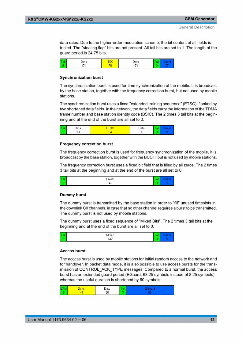
Normal burst, GMSK
The GSMK-modulated normal burst is used for data transmission on the traffic channeland on the control channels (except the RACH, PRACH, and CPRACH).
The normal burst contains two 57-bit long data fields for the transmission of the userinformation. The training sequence (TSC) in the center is flanked by two "stealing flag"bits (S1); each of them is set to 0. The 2 times 3 tail bits at the beginning and at the endof the burst are all set to 0, the 8.25-bit guard period at the end is transmission-free.
Normal burst, 8PSK
An 8PSK-modulated normal burst is also termed EDGE burst; see chapter 2.2.1, "GSMSignal Parameters", on page 10. EDGE bursts are used for data transmission at higher
General Description
GSM GeneratorR&S®CMW-KG2xx/-KM2xx/-KS2xx
12User Manual 1173.9634.02 ─ 06
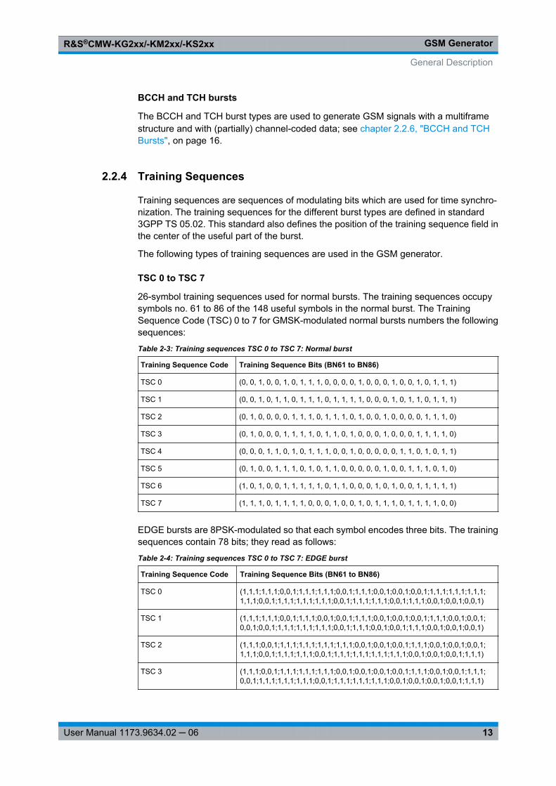
data rates. Due to the higher-order modulation scheme, the bit content of all fields istripled. The "stealing flag" bits are not present. All tail bits are set to 1. The length of theguard period is 24.75 bits.
Synchronization burst
The synchronization burst is used for time synchronization of the mobile. It is broadcastby the base station, together with the frequency correction burst, but not used by mobilestations.
The synchronization burst uses a fixed "extended training sequence" (ETSC), flanked bytwo shortened data fields. In the network, the data fields carry the information of the TDMAframe number and base station identity code (BSIC). The 2 times 3 tail bits at the begin-ning and at the end of the burst are all set to 0.
Frequency correction burst
The frequency correction burst is used for frequency synchronization of the mobile. It isbroadcast by the base station, together with the BCCH, but is not used by mobile stations.
The frequency correction burst uses a fixed bit field that is filled by all zeros. The 2 times3 tail bits at the beginning and at the end of the burst are all set to 0.
Dummy burst
The dummy burst is transmitted by the base station in order to "fill" unused timeslots inthe downlink C0 channels, in case that no other channel requires a burst to be transmitted.The dummy burst is not used by mobile stations.
The dummy burst uses a fixed sequence of "Mixed Bits". The 2 times 3 tail bits at thebeginning and at the end of the burst are all set to 0.
Access burst
The access burst is used by mobile stations for initial random access to the network andfor handover. In packet data mode, it is also possible to use access bursts for the trans-mission of CONTROL_ACK_TYPE messages. Compared to a normal burst, the accessburst has an extended guard period (EGuard, 68.25 symbols instead of 8.25 symbols)whereas the useful duration is shortened by 60 symbols.
General Description
GSM GeneratorR&S®CMW-KG2xx/-KM2xx/-KS2xx
13User Manual 1173.9634.02 ─ 06
BCCH and TCH bursts
The BCCH and TCH burst types are used to generate GSM signals with a multiframestructure and with (partially) channel-coded data; see chapter 2.2.6, "BCCH and TCHBursts", on page 16.
2.2.4 Training Sequences
Training sequences are sequences of modulating bits which are used for time synchro-nization. The training sequences for the different burst types are defined in standard3GPP TS 05.02. This standard also defines the position of the training sequence field inthe center of the useful part of the burst.
The following types of training sequences are used in the GSM generator.
TSC 0 to TSC 7
26-symbol training sequences used for normal bursts. The training sequences occupysymbols no. 61 to 86 of the 148 useful symbols in the normal burst. The TrainingSequence Code (TSC) 0 to 7 for GMSK-modulated normal bursts numbers the followingsequences:
Table 2-3: Training sequences TSC 0 to TSC 7: Normal burst
Training Sequence Code Training Sequence Bits (BN61 to BN86)
TSC 0 (0, 0, 1, 0, 0, 1, 0, 1, 1, 1, 0, 0, 0, 0, 1, 0, 0, 0, 1, 0, 0, 1, 0, 1, 1, 1)
TSC 1 (0, 0, 1, 0, 1, 1, 0, 1, 1, 1, 0, 1, 1, 1, 1, 0, 0, 0, 1, 0, 1, 1, 0, 1, 1, 1)
TSC 2 (0, 1, 0, 0, 0, 0, 1, 1, 1, 0, 1, 1, 1, 0, 1, 0, 0, 1, 0, 0, 0, 0, 1, 1, 1, 0)
TSC 3 (0, 1, 0, 0, 0, 1, 1, 1, 1, 0, 1, 1, 0, 1, 0, 0, 0, 1, 0, 0, 0, 1, 1, 1, 1, 0)
TSC 4 (0, 0, 0, 1, 1, 0, 1, 0, 1, 1, 1, 0, 0, 1, 0, 0, 0, 0, 0, 1, 1, 0, 1, 0, 1, 1)
TSC 5 (0, 1, 0, 0, 1, 1, 1, 0, 1, 0, 1, 1, 0, 0, 0, 0, 0, 1, 0, 0, 1, 1, 1, 0, 1, 0)
TSC 6 (1, 0, 1, 0, 0, 1, 1, 1, 1, 1, 0, 1, 1, 0, 0, 0, 1, 0, 1, 0, 0, 1, 1, 1, 1, 1)
TSC 7 (1, 1, 1, 0, 1, 1, 1, 1, 0, 0, 0, 1, 0, 0, 1, 0, 1, 1, 1, 0, 1, 1, 1, 1, 0, 0)
EDGE bursts are 8PSK-modulated so that each symbol encodes three bits. The trainingsequences contain 78 bits; they read as follows:
Table 2-4: Training sequences TSC 0 to TSC 7: EDGE burst
Training Sequence Code Training Sequence Bits (BN61 to BN86)
TSC 0 (1,1,1;1,1,1;0,0,1;1,1,1;1,1,1;0,0,1;1,1,1;0,0,1;0,0,1;0,0,1;1,1,1;1,1,1;1,1,1;1,1,1;0,0,1;1,1,1;1,1,1;1,1,1;0,0,1;1,1,1;1,1,1;0,0,1;1,1,1;0,0,1;0,0,1;0,0,1)
TSC 1 (1,1,1;1,1,1;0,0,1;1,1,1;0,0,1;0,0,1;1,1,1;0,0,1;0,0,1;0,0,1;1,1,1;0,0,1;0,0,1;0,0,1;0,0,1;1,1,1;1,1,1;1,1,1;0,0,1;1,1,1;0,0,1;0,0,1;1,1,1;0,0,1;0,0,1;0,0,1)
TSC 2 (1,1,1;0,0,1;1,1,1;1,1,1;1,1,1;1,1,1;0,0,1;0,0,1;0,0,1;1,1,1;0,0,1;0,0,1;0,0,1;1,1,1;0,0,1;1,1,1;1,1,1;0,0,1;1,1,1;1,1,1;1,1,1;1,1,1;0,0,1;0,0,1;0,0,1;1,1,1)
TSC 3 (1,1,1;0,0,1;1,1,1;1,1,1;1,1,1;0,0,1;0,0,1;0,0,1;0,0,1;1,1,1;0,0,1;0,0,1;1,1,1;0,0,1;1,1,1;1,1,1;1,1,1;0,0,1;1,1,1;1,1,1;1,1,1;0,0,1;0,0,1;0,0,1;0,0,1;1,1,1)
General Description
GSM GeneratorR&S®CMW-KG2xx/-KM2xx/-KS2xx
14User Manual 1173.9634.02 ─ 06
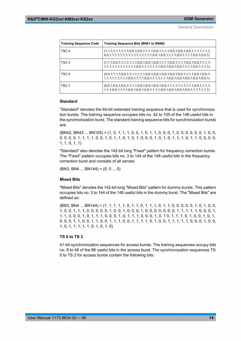
Training Sequence Code Training Sequence Bits (BN61 to BN86)
TSC 4 (1,1,1;1,1,1;1,1,1;0,0,1;0,0,1;1,1,1;0,0,1;1,1,1;0,0,1;0,0,1;0,0,1;1,1,1;1,1,1;0,0,1;1,1,1;1,1,1;1,1,1;1,1,1;1,1,1;0,0,1;0,0,1;1,1,1;0,0,1;1,1,1;0,0,1;0,0,1)
TSC 5 (1,1,1;0,0,1;1,1,1;1,1,1;0,0,1;0,0,1;0,0,1;1,1,1;0,0,1;1,1,1;0,0,1;0,0,1;1,1,1;1,1,1;1,1,1;1,1,1;1,1,1;0,0,1;1,1,1;1,1,1;0,0,1;0,0,1;0,0,1;1,1,1;0,0,1;1,1,1)
TSC 6 (0,0,1;1,1,1;0,0,1;1,1,1;1,1,1;0,0,1;0,0,1;0,0,1;0,0,1;0,0,1;1,1,1;0,0,1;0,0,1;1,1,1;1,1,1;1,1,1;0,0,1;1,1,1;0,0,1;1,1,1;1,1,1;0,0,1;0,0,1;0,0,1;0,0,1;0,0,1)
TSC 7 (0,0,1;0,0,1;0,0,1;1,1,1;0,0,1;0,0,1;0,0,1;0,0,1;1,1,1;1,1,1;1,1,1;0,0,1;1,1,1;1,1,1;0,0,1;1,1,1;0,0,1;0,0,1;0,0,1;1,1,1;0,0,1;0,0,1;0,0,1;0,0,1;1,1,1;1,1,1)
Standard
"Standard" denotes the 64-bit extended training sequence that is used for synchroniza-tion bursts. The training sequence occupies bits no. 42 to 105 of the 148 useful bits inthe synchronization burst. The standard training sequence bits for synchronization burstsare:
(BN42, BN43 ... BN105) = (1, 0, 1, 1, 1, 0, 0, 1, 0, 1, 1, 0, 0, 0, 1, 0, 0, 0, 0, 0, 0, 1, 0, 0,0, 0, 0, 0, 1, 1, 1, 1, 0, 0, 1, 0, 1, 1, 0, 1, 0, 1, 0, 0, 0, 1, 0, 1, 0, 1, 1, 1, 0, 1, 1, 0, 0, 0, 0,1, 1, 0, 1, 1)
"Standard" also denotes the 142-bit long "Fixed" pattern for frequency correction bursts.The "Fixed" pattern occupies bits no. 3 to 144 of the 148 useful bits in the frequencycorrection burst and consists of all zeroes:
(BN3, BN4 ... BN144) = (0, 0 ... 0)
Mixed Bits
"Mixed Bits" denotes the 142-bit long "Mixed Bits" pattern for dummy bursts. This patternoccupies bits no. 3 to 144 of the 148 useful bits in the dummy burst. The "Mixed Bits" aredefined as:
(BN3, BN4 ... BN144) = (1, 1, 1, 1, 1, 0, 1, 1, 0, 1, 1, 1, 0, 1, 1, 0, 0, 0, 0, 0, 1, 0, 1, 0, 0,1, 0, 0, 1, 1, 1, 0, 0, 0, 0, 0, 1, 0, 0, 1, 0, 0, 0, 1, 0, 0, 0, 0, 0, 0, 0, 1, 1, 1, 1, 1, 0, 0, 0, 1,1, 1, 0, 0, 0, 1, 0, 1, 1, 1, 0, 0, 0, 1, 0, 1, 1, 1, 0, 0, 0, 1, 0, 1 0, 1, 1, 1, 0, 1, 0, 0, 1, 0, 1,0, 0, 0, 1, 1, 0, 0, 1, 1, 0, 0, 1, 1, 1, 0, 0, 1, 1, 1, 1, 0, 1, 0, 0, 1, 1, 1, 1, 1, 0, 0, 0, 1, 0, 0,1, 0, 1, 1, 1, 1, 1, 0, 1, 0, 1, 0)
TS 0 to TS 2
41-bit synchronization sequences for access bursts. The training sequences occupy bitsno. 8 to 48 of the 88 useful bits in the access burst. The synchronization sequences TS0 to TS 2 for access bursts contain the following bits:
General Description

GSM GeneratorR&S®CMW-KG2xx/-KM2xx/-KS2xx
15User Manual 1173.9634.02 ─ 06
Table 2-5: Training sequences TS 0 to TS 2: Access burst
Training Sequence Code Training Sequence Bits (BN61 to BN86)
TS 0 0, 1, 0, 0, 1, 0, 1, 1, 0, 1, 1, 1, 1, 1, 1, 1, 1, 0, 0, 1, 1, 0, 0,1, 1, 0, 1, 0, 1, 0, 1,0, 0, 0, 1, 1, 1, 1, 0, 0, 0)
TS 1 (0, 1, 0, 1, 0, 1, 0, 0, 1, 1, 1, 1, 1, 0, 0, 0, 1, 0, 0, 0, 0, 1, 1, 0, 0, 0, 1, 0, 1, 1, 1,1, 0, 0, 1, 0, 0, 1, 1, 0, 1)
TS 2 (1, 1, 1, 0, 1, 1, 1, 1, 0, 0, 1, 0, 0, 1, 1, 1, 0, 1, 0, 1, 0, 1, 1, 0, 0, 0, 0, 0, 1, 1, 0,1, 1, 0, 1, 1, 1, 0, 1, 1, 1)
2.2.5 Power Control Levels
Power control levels (PCL) are used for dynamic control of the mobile power. The PCLrange depends on the GSM band as shown below (phase 2 specifications).
Power Control Level(PCL)
Pnom [dBm], GSM 400/GT 800/700/850/900
Pnom [dBm], GSM 1800 Pnom [dBm], GSM 1900
0
1
2
3
4
5
6
7
8
9
10
11
12
13
14
15
16
17
18
39
39
39
37
35
33
31
29
27
25
23
21
19
17
15
13
11
9
7
30
28
26
24
22
20
18
16
14
12
10
8
6
4
2
0
0
0
0
30
28
26
24
22
20
18
16
14
12
10
8
6
4
2
0
0
0
0
19 – 28 5 0 0
29
30
31
5
5
5
36
34
32
0
33
32
General Description
GSM GeneratorR&S®CMW-KG2xx/-KM2xx/-KS2xx
16User Manual 1173.9634.02 ─ 06
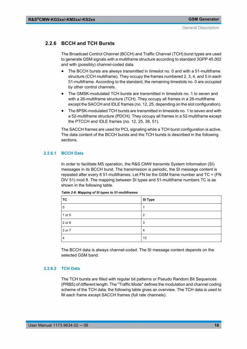
2.2.6 BCCH and TCH Bursts
The Broadcast Control Channel (BCCH) and Traffic Channel (TCH) burst types are usedto generate GSM signals with a multiframe structure according to standard 3GPP 45.002and with (possibly) channel-coded data.● The BCCH bursts are always transmitted in timeslot no. 0 and with a 51-multiframe
structure (CCH multiframe). They occupy the frames numbered 2, 3, 4, and 5 in each51-multiframe. According to the standard, the remaining timeslots no. 0 are occupiedby other control channels.
● The GMSK-modulated TCH bursts are transmitted in timeslots no. 1 to seven andwith a 26-multiframe structure (TCH). They occupy all frames in a 26-multiframeexcept the SACCH and IDLE frames (no. 12, 25, depending on the slot configuration).
● The 8PSK-modulated TCH bursts are transmitted in timeslots no. 1 to seven and witha 52-multiframe structure (PDCH). They occupy all frames in a 52-multiframe exceptthe PTCCH and IDLE frames (no. 12, 25, 38, 51).
The SACCH frames are used for PCL signaling while a TCH burst configuration is active.The data content of the BCCH bursts and the TCH bursts is described in the followingsections.
2.2.6.1 BCCH Data
In order to facilitate MS operation, the R&S CMW transmits System Information (SI)messages in its BCCH burst. The transmission is periodic, the SI message content isrepeated after every 8 51-multiframes. Let FN be the GSM frame number and TC = (FNDIV 51) mod 8. The mapping between SI types and 51-multiframe numbers TC is asshown in the following table.
Table 2-6: Mapping of SI types to 51-multiframes
TC SI Type
0 1
1 or 5 2
2 or 6 3
3 or 7 4
4 13
The BCCH data is always channel-coded. The SI message content depends on theselected GSM band.
2.2.6.2 TCH Data
The TCH bursts are filled with regular bit patterns or Pseudo Random Bit Sequences(PRBS) of different length. The "Traffic Mode" defines the modulation and channel codingscheme of the TCH data; the following table gives an overview. The TCH data is used tofill each frame except SACCH frames (full rate channels).
General Description
GSM GeneratorR&S®CMW-KG2xx/-KM2xx/-KS2xx
17User Manual 1173.9634.02 ─ 06
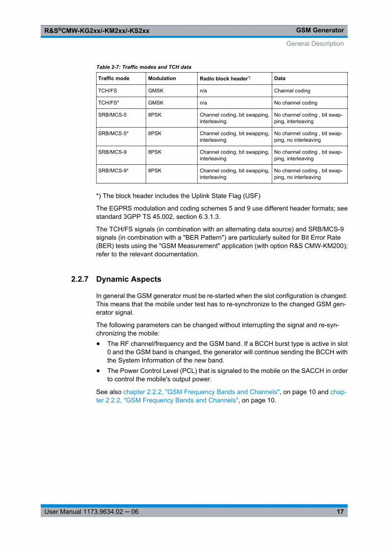
Table 2-7: Traffic modes and TCH data
Traffic mode Modulation Radio block header*) Data
TCH/FS GMSK n/a Channel coding
TCH/FS* GMSK n/a No channel coding
SRB/MCS-5 8PSK Channel coding, bit swapping,interleaving
No channel coding , bit swap-ping, interleaving
SRB/MCS-5* 8PSK Channel coding, bit swapping,interleaving
No channel coding , bit swap-ping, no interleaving
SRB/MCS-9 8PSK Channel coding, bit swapping,interleaving
No channel coding , bit swap-ping, interleaving
SRB/MCS-9* 8PSK Channel coding, bit swapping,interleaving
No channel coding , bit swap-ping, no interleaving
*) The block header includes the Uplink State Flag (USF)
The EGPRS modulation and coding schemes 5 and 9 use different header formats; seestandard 3GPP TS 45.002, section 6.3.1.3.
The TCH/FS signals (in combination with an alternating data source) and SRB/MCS-9signals (in combination with a "BER Pattern") are particularly suited for Bit Error Rate(BER) tests using the "GSM Measurement" application (with option R&S CMW-KM200);refer to the relevant documentation.
2.2.7 Dynamic Aspects
In general the GSM generator must be re-started when the slot configuration is changed.This means that the mobile under test has to re-synchronize to the changed GSM gen-erator signal.
The following parameters can be changed without interrupting the signal and re-syn-chronizing the mobile:● The RF channel/frequency and the GSM band. If a BCCH burst type is active in slot
0 and the GSM band is changed, the generator will continue sending the BCCH withthe System Information of the new band.
● The Power Control Level (PCL) that is signaled to the mobile on the SACCH in orderto control the mobile's output power.
See also chapter 2.2.2, "GSM Frequency Bands and Channels", on page 10 and chap-ter 2.2.2, "GSM Frequency Bands and Channels", on page 10.
General Description
GSM GeneratorR&S®CMW-KG2xx/-KM2xx/-KS2xx
18User Manual 1173.9634.02 ─ 06
2.3 Application Sheets
Application sheets describe short application examples for select issues and providerelated background information. The following application sheets are related to the "GSMGenerator" firmware application.
● Generating and Measuring a GSM Signal..............................................................18● GSM BER Tests on Real-Time Signals..................................................................22
2.3.1 Generating and Measuring a GSM Signal
This application sheet describes the generation and analysis of a GSM multislot signalcontaining different burst types and levels. The signal is generated by the real-time GSMgenerator; the GSM multi evaluation measurement is used to visualize the generatedsignal. Some basic measurement settings, in particular the trigger source and the accessburst search, must be adjusted to the signal properties.
2.3.1.1 Options and Equipment Required
Generation and analysis of real-time GSM signals requires an R&S CMW500 or R&SCMW280 tester which is equipped with the following options:● Option R&S CMW-KG200, "GSM Generator"● Option R&S CMW-KM200, "GSM TX Measurements"
2.3.1.2 General Procedure
The signal is generated and analyzed as follows:
1. Define the signal properties using the "GSM – Generator" dialog and turn on thegenerator.
2. Open the "GSM TX Measurement – Multi Evaluation" dialog and adjust the mea-surement settings.
3. Select the appropriate views to display the signal properties.
You can use different output and input connectors for the generated signal. In this caseyou have to connect both connectors using a coax cable. Alternatively (in particular, ifabsolute levels are not part of the analysis), you can even use the same bidirectional RFconnector for the generated and measured signal.
2.3.1.3 Generating the Signal
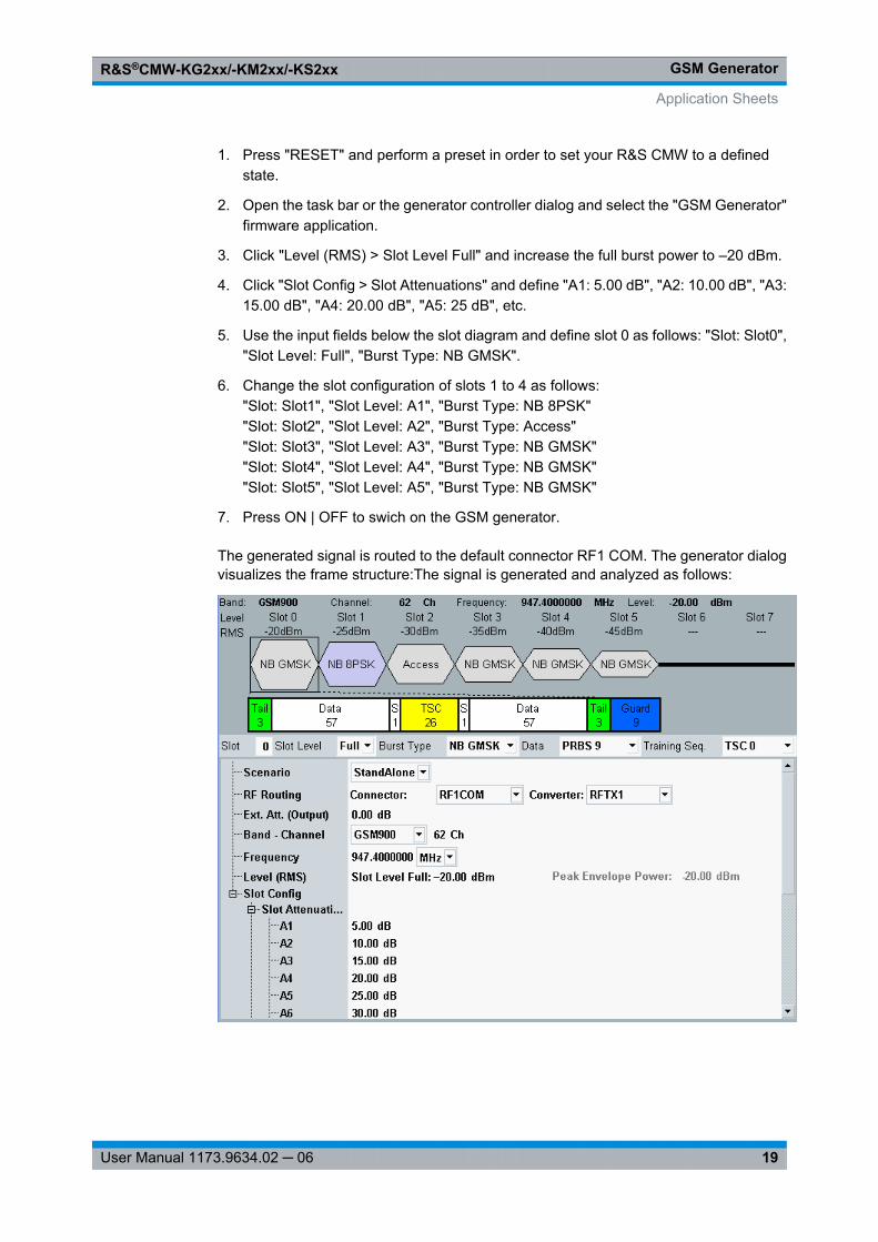
To generate a multislot GSM signal with the specific frame structure shown below, pro-ceed as follows:
Application Sheets
GSM GeneratorR&S®CMW-KG2xx/-KM2xx/-KS2xx
19User Manual 1173.9634.02 ─ 06
1. Press "RESET" and perform a preset in order to set your R&S CMW to a definedstate.
2. Open the task bar or the generator controller dialog and select the "GSM Generator"firmware application.
3. Click "Level (RMS) > Slot Level Full" and increase the full burst power to –20 dBm.
4. Click "Slot Config > Slot Attenuations" and define "A1: 5.00 dB", "A2: 10.00 dB", "A3:15.00 dB", "A4: 20.00 dB", "A5: 25 dB", etc.
5. Use the input fields below the slot diagram and define slot 0 as follows: "Slot: Slot0","Slot Level: Full", "Burst Type: NB GMSK".
6. Change the slot configuration of slots 1 to 4 as follows:"Slot: Slot1", "Slot Level: A1", "Burst Type: NB 8PSK""Slot: Slot2", "Slot Level: A2", "Burst Type: Access""Slot: Slot3", "Slot Level: A3", "Burst Type: NB GMSK""Slot: Slot4", "Slot Level: A4", "Burst Type: NB GMSK""Slot: Slot5", "Slot Level: A5", "Burst Type: NB GMSK"
7. Press ON | OFF to swich on the GSM generator.
The generated signal is routed to the default connector RF1 COM. The generator dialogvisualizes the frame structure:The signal is generated and analyzed as follows:
Application Sheets
GSM GeneratorR&S®CMW-KG2xx/-KM2xx/-KS2xx
20User Manual 1173.9634.02 ─ 06
2.3.1.4 Adjusting the Measurement Settings
To adjust the multi evaluation measurement to the properties of the signal, proceed asfollows:
1. Open the task bar or the generator controller dialog and select the "GSM Multi Eval."firmware application.
2. Press "ON | OFF" to switch on the measurement.
3. Click "RF Settings > Frequency / Channel" and set the analyzer to the RF carrierfrequency of 947.4 MHz. You may leave the remaining "RF Settings" unchanged.
4. Click "Trigger > Trigger Source: Acquisition", leaving the remaining "Trigger" settingsunchanged.
5. Click "Config." to open the "GSM Multi Evaluation Configuration" dialog.
6. In the configuration dialog, select "Measurement Control > Access Burst Search: On".
7. Close the configuration dialog and return to the measurement dialog.
The "Acquisition" trigger locates the 2-slot gap in timeslots 6 and 7 to determine thebeginning of the frame; the enabled access burst search is a prerequisite for the accessburst measurement.
2.3.1.5 Visualizing the Signal
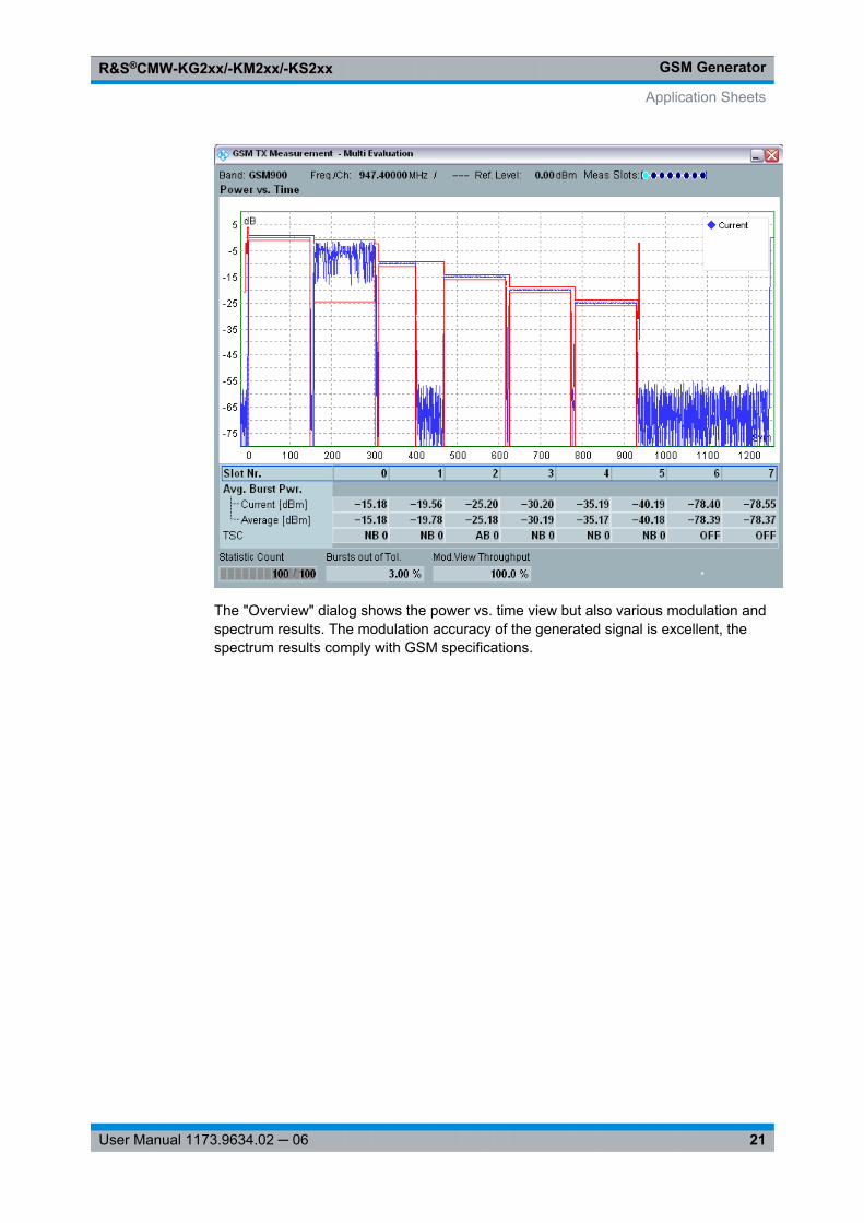
In the "GSM TX Measurement – Multi Evaluation" diagram, you can use the "Display"settings to select a view and optimize its appearance. Several of the "GSM TX Measure-ment – Multi Evaluation" views are well suited for the analysis of the generated multislotsignal.
The "Power vs. Time" view below shows the entire GSM frame with the six active andtwo inactive slots. Normal bursts use a constant-envelope (GMSK) modulation scheme,causing only small power variations on the useful part of the burst. The EDGE burst inslot no. 1 is clearly distinguished by its large power variations, due to 8PSK modulation.The access burst in slot no. 3 is shorter than the other burst types. The power stepsbetween the slots correspond to the selected attenuation values.
Application Sheets
GSM GeneratorR&S®CMW-KG2xx/-KM2xx/-KS2xx
21User Manual 1173.9634.02 ─ 06
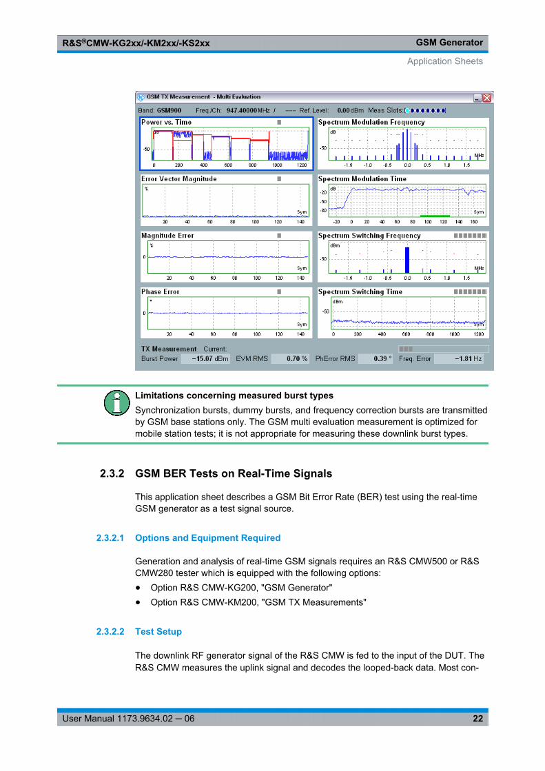
The "Overview" dialog shows the power vs. time view but also various modulation andspectrum results. The modulation accuracy of the generated signal is excellent, thespectrum results comply with GSM specifications.
Application Sheets
GSM GeneratorR&S®CMW-KG2xx/-KM2xx/-KS2xx
22User Manual 1173.9634.02 ─ 06
Limitations concerning measured burst typesSynchronization bursts, dummy bursts, and frequency correction bursts are transmittedby GSM base stations only. The GSM multi evaluation measurement is optimized formobile station tests; it is not appropriate for measuring these downlink burst types.
2.3.2 GSM BER Tests on Real-Time Signals
This application sheet describes a GSM Bit Error Rate (BER) test using the real-timeGSM generator as a test signal source.
2.3.2.1 Options and Equipment Required
Generation and analysis of real-time GSM signals requires an R&S CMW500 or R&SCMW280 tester which is equipped with the following options:● Option R&S CMW-KG200, "GSM Generator"● Option R&S CMW-KM200, "GSM TX Measurements"
2.3.2.2 Test Setup
The downlink RF generator signal of the R&S CMW is fed to the input of the DUT. TheR&S CMW measures the uplink signal and decodes the looped-back data. Most con-
Application Sheets
GSM GeneratorR&S®CMW-KG2xx/-KM2xx/-KS2xx
23User Manual 1173.9634.02 ─ 06
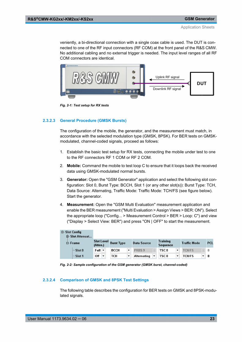
veniently, a bi-directional connection with a single coax cable is used. The DUT is con-nected to one of the RF input connectors (RF COM) at the front panel of the R&S CMW.No additional cabling and no external trigger is needed. The input level ranges of all RFCOM connectors are identical.
Fig. 2-1: Test setup for RX tests
2.3.2.3 General Procedure (GMSK Bursts)
The configuration of the mobile, the generator, and the measurement must match, inaccordance with the selected modulation type (GMSK, 8PSK). For BER tests on GMSK-modulated, channel-coded signals, proceed as follows:
1. Establish the basic test setup for RX tests, connecting the mobile under test to oneto the RF connectors RF 1 COM or RF 2 COM.
2. Mobile: Command the mobile to test loop C to ensure that it loops back the receiveddata using GMSK-modulated normal bursts.
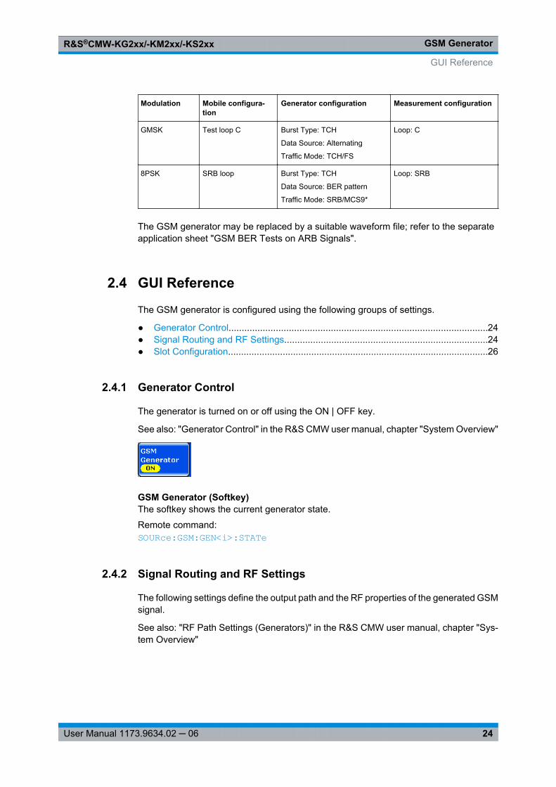
3. Generator: Open the "GSM Generator" application and select the following slot con-figuration: Slot 0, Burst Type: BCCH, Slot 1 (or any other slot(s)): Burst Type: TCH,Data Source: Alternating, Traffic Mode: Traffic Mode: TCH/FS (see figure below).Start the generator.
4. Measurement: Open the "GSM Multi Evaluation" measurement application andenable the BER measurement ("Multi Evaluation > Assign Views > BER: ON"). Selectthe appropriate loop ("Config... > Measurement Control > BER > Loop: C") and view("Display > Select View: BER") and press "ON | OFF" to start the measurement.
Fig. 2-2: Sample configuration of the GSM generator (GMSK burst, channel-coded)
2.3.2.4 Comparison of GMSK and 8PSK Test Settings
The following table describes the configuration for BER tests on GMSK and 8PSK-modu-lated signals.
Application Sheets
GSM GeneratorR&S®CMW-KG2xx/-KM2xx/-KS2xx
24User Manual 1173.9634.02 ─ 06
Modulation Mobile configura-tion
Generator configuration Measurement configuration
GMSK Test loop C Burst Type: TCH
Data Source: Alternating
Traffic Mode: TCH/FS
Loop: C
8PSK SRB loop Burst Type: TCH
Data Source: BER pattern
Traffic Mode: SRB/MCS9*
Loop: SRB
The GSM generator may be replaced by a suitable waveform file; refer to the separateapplication sheet "GSM BER Tests on ARB Signals".
2.4 GUI Reference
The GSM generator is configured using the following groups of settings.
● Generator Control...................................................................................................24● Signal Routing and RF Settings..............................................................................24● Slot Configuration....................................................................................................26
2.4.1 Generator Control
The generator is turned on or off using the ON | OFF key.
See also: "Generator Control" in the R&S CMW user manual, chapter "System Overview"
GSM Generator (Softkey)The softkey shows the current generator state.
Remote command: SOURce: GSM: GEN<i>: STATe
2.4.2 Signal Routing and RF Settings
The following settings define the output path and the RF properties of the generated GSMsignal.
See also: "RF Path Settings (Generators)" in the R&S CMW user manual, chapter "Sys-tem Overview"
GUI Reference
GSM GeneratorR&S®CMW-KG2xx/-KM2xx/-KS2xx
25User Manual 1173.9634.02 ─ 06
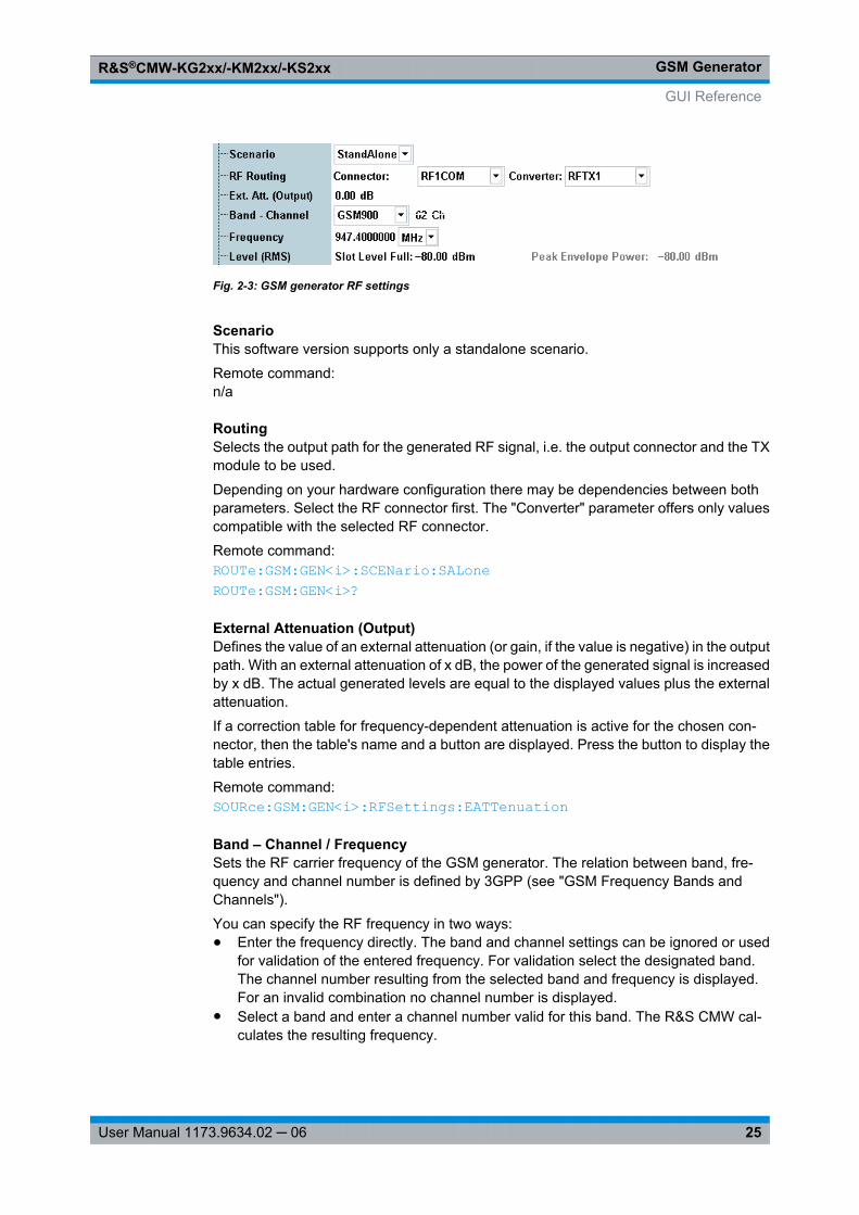
Fig. 2-3: GSM generator RF settings
ScenarioThis software version supports only a standalone scenario.
Remote command: n/a
RoutingSelects the output path for the generated RF signal, i.e. the output connector and the TXmodule to be used.
Depending on your hardware configuration there may be dependencies between bothparameters. Select the RF connector first. The "Converter" parameter offers only valuescompatible with the selected RF connector.
Remote command: ROUTe: GSM: GEN<i>: SCENario: SALone ROUTe: GSM: GEN<i>?
External Attenuation (Output)Defines the value of an external attenuation (or gain, if the value is negative) in the outputpath. With an external attenuation of x dB, the power of the generated signal is increasedby x dB. The actual generated levels are equal to the displayed values plus the externalattenuation.
If a correction table for frequency-dependent attenuation is active for the chosen con-nector, then the table's name and a button are displayed. Press the button to display thetable entries.
Remote command: SOURce: GSM: GEN<i>: RFSettings: EATTenuation
Band – Channel / FrequencySets the RF carrier frequency of the GSM generator. The relation between band, fre-quency and channel number is defined by 3GPP (see "GSM Frequency Bands andChannels").
You can specify the RF frequency in two ways:● Enter the frequency directly. The band and channel settings can be ignored or used
for validation of the entered frequency. For validation select the designated band.The channel number resulting from the selected band and frequency is displayed.For an invalid combination no channel number is displayed.
● Select a band and enter a channel number valid for this band. The R&S CMW cal-culates the resulting frequency.
GUI Reference
GSM GeneratorR&S®CMW-KG2xx/-KM2xx/-KS2xx
26User Manual 1173.9634.02 ─ 06
Note: Dynamic band and channel change . You can change the channel and even theGSM band while the GSM generator is running. There is no need to re-start the generatorand re-synchronize the mobile under test. If a BCCH burst type is active in slot 0 and theGSM band is changed, the generator will continue sending the BCCH with the SystemInformation of the new band.
Remote command: SOURce: GSM: GEN<i>: BAND SOURce: GSM: GEN<i>: RFSettings: FREQuency SOURce: GSM: GEN<i>: CHANnel
Level (RMS)Sets the base level of the generator ("Slot Level Full"). The individual slot levels aredefined relative to this base level.
The resulting actual Peak Envelope Power (PEP) is measured and displayed for infor-mation when the generator is turned on. The indicated PEP corresponds to the actualpeak output level at the output connector, assuming the External Attenuation (Output) iszero.
The signal at the output connector is limited to the maximum level stated in the data sheet.When the settings result in a signal exceeding this limit, the Level (RMS) is decreasedautomatically.
Remote command: SOURce: GSM: GEN<i>: RFSettings: LEVel: RMS SOURce: GSM: GEN<i>: RFSettings: LEVel: PEAK?
2.4.3 Slot Configuration
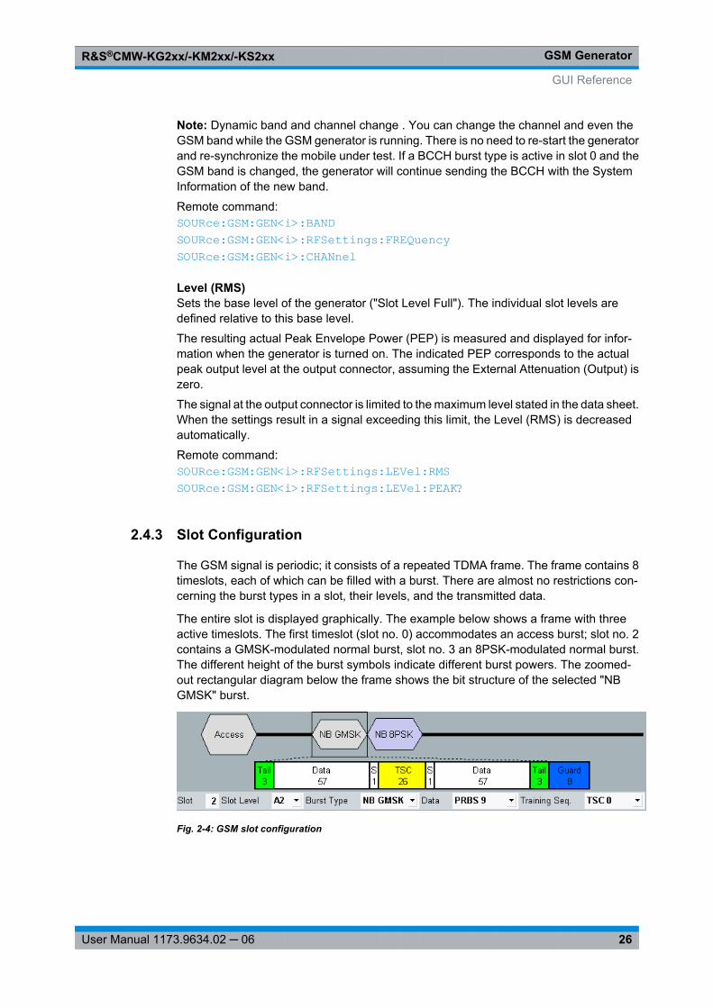
The GSM signal is periodic; it consists of a repeated TDMA frame. The frame contains 8timeslots, each of which can be filled with a burst. There are almost no restrictions con-cerning the burst types in a slot, their levels, and the transmitted data.
The entire slot is displayed graphically. The example below shows a frame with threeactive timeslots. The first timeslot (slot no. 0) accommodates an access burst; slot no. 2contains a GMSK-modulated normal burst, slot no. 3 an 8PSK-modulated normal burst.The different height of the burst symbols indicate different burst powers. The zoomed-out rectangular diagram below the frame shows the bit structure of the selected "NBGMSK" burst.
Fig. 2-4: GSM slot configuration
GUI Reference

GSM GeneratorR&S®CMW-KG2xx/-KM2xx/-KS2xx
27User Manual 1173.9634.02 ─ 06
The signal properties in each timeslot are defined below the diagrams. Alternatively, youcan access all slot settings in the settings tree below the diagram area via "Slot Config.> Frame".
SlotSelects the slot to be configured; see "GSM Signal Parameters" on page 3
Remote command: No explicit command. The parameters for all slots are defined with a single command;see below.
Slot LevelSelects the average burst power in the slot. "Off" turns off the slot power entirely: thetimeslot is inactive.
The average burst power is the average power in the useful part of the burst (see stand-ards 3GPP TS 05.05 and 3GPP TS 05.02), excluding the guard period where the mobiletransmission is attenuated (power-up and power-down ramps). For normal bursts theuseful part comprises 147 symbol periods; it is centered around the transition betweenbits 13/14 of the training sequence; see "Burst Types" on page 5.
Note: Absolute and relative slot levels . The maximum slot level to be set is the "Full" slotlevel. With this selection, the average burst power corresponds to the "Slot Level Full"setting in the tabular section of the generator dialog.To define lower slot levels, use one of the "Slot Attenuations" A1 to A7, which will reducethe burst power by a dB-factor relative to the full level. In this way you can set the levelin each slot independently.
Remote command: SOURce: GSM: GEN<i>: SCONfig: SLEVel
Burst TypeThe burst type defines the length, modulation and bit structure of the burst; see "BurstTypes" on page 5.
Broadcast Control Channel (BCCH) bursts are reserved for slot 0, while Traffic Channel(TCH) bursts are reserved for slots 1 to 7.
Remote command: SOURce: GSM: GEN<i>: SCONfig: BTYPe
Data SourceSelects the bit sequence to be transmitted in the data fields of the bursts.● All 0: Regular bit pattern 0000 ...● All 1: Regular bit pattern 1111 ...● Alternating: Regular bit pattern 010101 ... The "Alternating" pattern is suitable for
BER tests on GMSK-modulated signals using the "GSM Measurement" application(with option R&S CMW-KM200); see chapter 2.3.2, "GSM BER Tests on Real-TimeSignals", on page 22.
● PRBS9 ... PRBS23: Pseudo Random Bit Sequences of different length according toCCITT 0.153
● BER Pattern: PRBS sequence, to be used for a 8PSK-modulated signal with mod-ulation and coding scheme MCS-9 ("Traffic Mode: SRB MCS-9 or SRB MCS-9*").The "BER Pattern" is suitable for BER tests on EGPRS channels using the "GSM
GUI Reference
GSM GeneratorR&S®CMW-KG2xx/-KM2xx/-KS2xx
28User Manual 1173.9634.02 ─ 06
Measurement" application (with option R&S CMW-KM200); see chapter 2.3.2, "GSMBER Tests on Real-Time Signals", on page 22.
The data fields for frequency correction bursts, dummy bursts, and BCCH bursts are notconfigurable, so the selected "Data" is not valid for these burst types. The BCCH bursts(slot 0) carry System Information messages; see chapter 2.2.6, "BCCH and TCHBursts", on page 16.
Remote command: SOURce: GSM: GEN<i>: SCONfig: DSOurce
Training SequenceSets one of the specified GSM training sequences TSC 0 to TSC 7 for the burst; see"Training Sequences" on page 6 . For access bursts, only three training sequences TS0 to TS 2 are available. Synchronization, frequency correction, and dummy bursts usefixed or arbitrary ("Mixed") sequences, so no training sequence selection is possible.
Remote command: SOURce: GSM: GEN<i>: SCONfig: TSEQuence
Slot Config > Slot AttenuationsConfigures up to 7 relative slot levels, to be used for individual "Slot Level" settings. If the"Slot Level" is set to one of the A<n> values (<n> = 1 to 7), the burst level in the slot isreduced to:
Burst level = <Slot Level Full> — A<n>
Remote command: SOURce: GSM: GEN<i>: SCONfig: SATTenuation
Slot Config > FrameTabular overview of the burst settings in all 8 timeslots.
In addition to the settings described above, the "Frame" section provides the "TrafficMode" and "PCL" selection for traffic channels (TCH).
Slot Config > Frame > Traffic ModeSelects the modulation scheme and coding for the transfer of speech data or radio blocksvia traffic channels. The setting is valid for traffic channel burst types only (slots 1 to 7).Thetraffic mode for slot 0 is unavailable irrespective of the burst type setting.● TCH/FS: Traffic channel / full rate speech● TCH/FS*: Traffic channel / full rate speech uncoded● SRB MCS-5: EGPRS Switching Radio Blocks (8PSK modulation), modulation and
coding scheme MCS-5, channel-coded header and interleaved data● SRB MCS-5*: Like before, but non-interleaved data● SRB MCS-9 EGPRS Switching Radio Blocks (8PSK modulation), modulation and
coding scheme MCS-9, channel-coded header and interleaved data● SRB MCS-9*: Like before, but non-interleaved dataFor more detailed information refer to chapter 2.2.6.2, "TCH Data", on page 16.
Remote command: SOURce: GSM: GEN<i>: SCONfig: TMODe
GUI Reference
GSM GeneratorR&S®CMW-KG2xx/-KM2xx/-KS2xx
29User Manual 1173.9634.02 ─ 06
Slot Config > Frame > PCLXE "PCL (GSM Generator)" Selects the Power Control Level (PCL) that is signaled tothe mobile under test on the Slow Associated Control Channel (SACCH) in order to con-trol its output power. The setting is valid for traffic channel (TCH) burst types and speechchannels ("Traffic Mode: TCH/FS or TCH/FS*") only.
The PCL values for slots 1 to 7 control the output power of the mobile in the correspondingtimeslots 0 to 7. The PCL for slot 0 is ignored.
Note: Dynamic PCL change. You can change the PCL settings (and thus modify themobile output power) while the GSM generator is running. There is no need to re-startthe generator and re-synchronize the mobile under test.For more information refer to chapter 2.2.5, "Power Control Levels", on page 15.
Remote command: SOURce: GSM: GEN<i>: SCONfig: PCL
2.5 Programming
The following examples show how to control and configure the GSM generator via aremote-control program.
See also: "Remote Control" in the R&S CMW user manual
● Key Features...........................................................................................................29● Specifying General and RF Settings.......................................................................29● Slot Configuration....................................................................................................30● Switching on the Generator.....................................................................................30
2.5.1 Key Features
The GSM generator is programmed as follows:● The generator is controlled by SCPI commands with the following syn-
tax: ...:GSM:GEN:...● After a *RST, the generator must be switched on: SOURce:GSM:GEN:STATe ON.
*OPC? ensures that the RF generator signal is actually available at the selected RFoutput before the next command line is executed.
An RF signal is available at the selected RF output as soon as the RF generator hasreached the ON state. Use SOURce:GSM:GEN:STATe? to query the generator state.
2.5.2 Specifying General and RF Settings
FPRINT *************************************************************************FPRINT System-Reset FPRINT ************************************************************************* *RST; *OPC?*CLS; *OPC?
Programming
GSM GeneratorR&S®CMW-KG2xx/-KM2xx/-KS2xx
30User Manual 1173.9634.02 ─ 06
FPRINT *************************************************************************FPRINT Route output signal, define external attenuation.FPRINT ************************************************************************* ROUTe:GSM:GEN:SCENario:SALone RF1C, TX1 SOURce:GSM:GEN:RFSettings:EATTenuation 2.2
FPRINT ************************************************************************* FPRINT Set frequency and level.FPRINT ************************************************************************* SOURce:GSM:GEN:RFSettings:FREQuency 9.594E+008 SOURce:GSM:GEN:RFSettings:LEVel:RMS -70.0
FPRINT ************************************************************************* FPRINT Alternatively set the frequency indirectly via band and channelFPRINT (Channel 122 in GSM900 corresponds to 959.4 MHz).FPRINT ************************************************************************* SOURce:GSM:GEN:BAND G09 SOURce:GSM:GEN:CHANnel 122 SOURce:GSM:GEN:RFSettings:FREQuency?
WAITKEY >RF settings completed, press "OK" to configure slots<
2.5.3 Slot Configuration
FPRINT ************************************************************************* FPRINT Define multislot configuration in timeslots 0 to 7: FPRINT Define slot attenuations, define level, burst type, FPRINT data source, and training sequence for each slot. FPRINT ************************************************************************* SOURce:GSM:GEN:SCONfig:SATTenuation 5.000E00, 1.000E+01, 1.500E+01, 2.000E+01, 2.500E+01, 3.000E+01, 3.500E+01 SOURce:GSM:GEN:SCONfig:SLEVel FULL, A1, A2, A3, A4, OFF, OFF, OFF SOURce:GSM:GEN:SCONfig:BTYPe ACCess, GMSK, EPSK, DUMMy, SYNCh, FCOR, GMSK, GMSK SOURce:GSM:GEN:SCONfig:DSOurce PR9, PR9, PR9, PR9, PR9, PR9, PR9, PR9
WAITKEY >Slot configuration completed, press "OK" to turn the signal on<
2.5.4 Switching on the Generator
FPRINT ************************************************************************* FPRINT Switch on generator. With command synchronization, the queried FPRINT generator state is "ON". FPRINT ************************************************************************* SOURce:GSM:GEN:STATe ON; *OPC?SOURce:GSM:GEN:STATe?
FPRINT *************************************************************************
Programming
GSM GeneratorR&S®CMW-KG2xx/-KM2xx/-KS2xx
31User Manual 1173.9634.02 ─ 06
FPRINT Query the peak envelope power FPRINT ************************************************************************* SOURce:GSM:GEN:RFSettings:LEVel:PEAK?
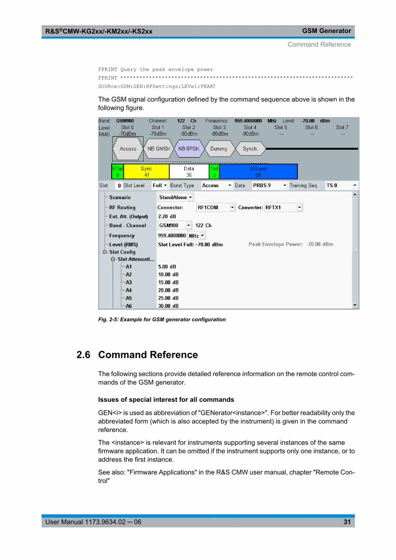
The GSM signal configuration defined by the command sequence above is shown in thefollowing figure.
Fig. 2-5: Example for GSM generator configuration
2.6 Command Reference
The following sections provide detailed reference information on the remote control com-mands of the GSM generator.
Issues of special interest for all commands
GEN<i> is used as abbreviation of "GENerator<instance>". For better readability only theabbreviated form (which is also accepted by the instrument) is given in the commandreference.
The <instance> is relevant for instruments supporting several instances of the samefirmware application. It can be omitted if the instrument supports only one instance, or toaddress the first instance.
See also: "Firmware Applications" in the R&S CMW user manual, chapter "Remote Con-trol"
Command Reference
GSM GeneratorR&S®CMW-KG2xx/-KM2xx/-KS2xx
32User Manual 1173.9634.02 ─ 06
Command groups
The commands of the GSM generator are divided into the groups listed below.
● Generator Control and States.................................................................................32● Signal Routing.........................................................................................................32● RF Settings.............................................................................................................34● Slot Configuration....................................................................................................36
2.6.1 Generator Control and States
The following command controls the generator and retrieves its state.
SOURce:GSM:GEN<i>:STATe <Control>
Turns the generator on or off.
See also: "Generator Control" in the R&S CMW user manual, chapter "Remote Control"
Setting parameters: <Control> ON | OFF
Switch generator ON or OFF*RST: OFF
Return values: <State> OFF | PENDing | ON
OFF: generator switched offPEND: generator switched on but no signal available yetON: generator switched on, signal available*RST: OFF
Example: See Switching on the Generator
Firmware/Software: V1.0.4.11
Manual operation: See "GSM Generator (Softkey)" on page 24
2.6.2 Signal Routing
The following commands select the connector for the generator and define an externalattenuation value.
ROUTe:GSM:GEN<i>:SCENario:SALone <TXConnector>, <RFConverter>
Activates the standalone scenario and selects the output path for the generated RF sig-nal, i.e. the RF connector and the TX module.
Depending on the installed hardware and the active sub-instrument or instance <i> onlya subset of the described parameter values is allowed. The *RST values and the mappingof virtual connector names to physical connectors also depend on the active sub-instru-ment or instance <i>.
Command Reference
GSM GeneratorR&S®CMW-KG2xx/-KM2xx/-KS2xx
33User Manual 1173.9634.02 ─ 06
All instruments are equipped with the RF 1 and RF 2 connectors and one RX and TXmodule. Additional RF connectors and RX/TX modules are optionally available for R&SCMW270 and R&S CMW500, but not for R&S CMW280.
See also: "Signal Path Settings" in the R&S CMW user manual, chapter "Remote Control"
Parameters:<TXConnector> RF1C | RF1O | RF2C | RF3C | RF3O | RF4C | RFAC | RFAO |
RFBCRF1C, RF2C, RF3C, RF4C, RF1O, RF3O:RF 1 COM to RF 4 COM and RF 1/3 OUT front panel connectorsRFAC, RFBC, RFAO:Virtual names for the RF COM and RF OUT connectors
<RFConverter> TX1 | TX2 | TX3 | TX4TX module for the output path
Example: See Specifying General and RF Settings
Firmware/Software: V2.0.10
Manual operation: See "Routing" on page 25
ROUTe:GSM:GEN<i>?
Queries the active test scenario and connector assignment.
Return values: <Scenario> SALone
standalone scenario (unique value)
<Controller> "CMWBase1"
<TXConnector> RF1C | RF1O | RF2C | RF3C | RF3O | RF4CRF 1 COM to RF 4 COM and RF 1/3 OUT front panel connectors
<RFConverter> TX1 | TX2 | TX3 | TX4TX module for the output path
Example: See Specifying General and RF Settings
Usage: Query only
Firmware/Software: V2.0.10
Manual operation: See "Routing" on page 25
SOURce:GSM:GEN<i>:RFSettings:EATTenuation <ExtRFOutAtt>
Defines an external attenuation (or gain, if the value is negative), to be applied to the RFoutput connector.
Command Reference
GSM GeneratorR&S®CMW-KG2xx/-KM2xx/-KS2xx
34User Manual 1173.9634.02 ─ 06
Parameters:<ExtRFOutAtt> Range: -50 dB to 90 dB
*RST: 0 dBDefault unit: dB
Example: See Specifying General and RF Settings
Firmware/Software: V1.0.4.11
Manual operation: See "External Attenuation (Output)" on page 25
2.6.3 RF Settings
The following commands configure general generator settings, e.g. frequency and baselevel.
SOURce:GSM:GEN<i>:RFSettings:FREQuency <Frequency>
Sets the RF carrier frequency of the GSM generator. Use SOURce: GSM: GEN<i>: CHANnel to specify the RF frequency as a GSM channel number.
Parameters:<Frequency> Range: 100 MHz to 6000 MHz (increment 0.1 Hz)
*RST: 947.4E+6 HzDefault unit: Hz
Example: See Specifying General and RF Settings
Firmware/Software: V1.0.4.11
Manual operation: See "Band – Channel / Frequency" on page 25
SOURce:GSM:GEN<i>:CHANnel <Channel>
Sets the RF carrier frequency as a GSM channel number.
If the channel number is valid for the current frequency band ( SOURce: GSM: GEN<i>: BAND ) the corresponding center frequency ( SOURce: GSM: GEN<i>: RFSettings: FREQuency ) is set.
If the channel number is queried while an out-of-band frequency is set, the response is"INV".
Parameters:<Channel> Range: Depending on the current frequency band
*RST: 62
Example: See Specifying General and RF Settings
Firmware/Software: V1.0.4.11
Manual operation: See "Band – Channel / Frequency" on page 25
Command Reference
GSM GeneratorR&S®CMW-KG2xx/-KM2xx/-KS2xx
35User Manual 1173.9634.02 ─ 06
SOURce:GSM:GEN<i>:BAND <Band>
Selects the frequency band of the generated GSM signal. The frequency band is relevantif channel numbers are used to specify the RF frequency ( SOURce: GSM: GEN<i>: CHANnel ).
Parameters:<Band> G04 | GG08 | G085 | G09 | G18 | G19
G04: GSM400GG08: GSMGT800G085: GSM850G09: GSM900G18: GSM1800G19: GSM1900*RST: G09
Example: See Specifying General and RF Settings
Firmware/Software: V1.0.4.11
Manual operation: See "Band – Channel / Frequency" on page 25
SOURce:GSM:GEN<i>:RFSettings:LEVel:RMS <RMS>
Sets the "Full-Slot Level" (RMS level) of the generator.
Parameters:<RMS> Range: –130 dBm to –5 dBm at RF 1 COM and RF 2 COM,
–122 dBm to +3 dBm at RF 1 OUT (increment 0.01dB); please also notice the ranges quoted in the datasheet.
*RST: -80 dBmDefault unit: dBm
Example: See Specifying General and RF Settings
Firmware/Software: V1.0.4.11
Manual operation: See "Level (RMS)" on page 26
SOURce:GSM:GEN<i>:RFSettings:LEVel:PEAK?
Queries the Peak Envelope Power (PEP) of the RF generator.
Return values: <PeakOutputPower> Range: : –130 dBm to –5 dBm at RF 1 COM and RF 2 COM,
–122 dBm to +3 dBm at RF 1 OUT (increment 0.01dB); please also notice the ranges quoted in the datasheet.
*RST: -80 dBmDefault unit: dBm
Example: See Switching on the Generator
Command Reference
GSM GeneratorR&S®CMW-KG2xx/-KM2xx/-KS2xx
36User Manual 1173.9634.02 ─ 06
Usage: Query only
Firmware/Software: V1.0.4.11
Manual operation: See "Level (RMS)" on page 26
2.6.4 Slot Configuration
The following commands configure the 8 timeslots of the generated GSM signal.
SOURce:GSM:GEN<i>:SCONfig:SLEVel <SlotLevel0>, <SlotLevel1>, <SlotLevel2>,<SlotLevel3>, <SlotLevel4>, <SlotLevel5>, <SlotLevel6>, <SlotLevel7>
Defines the average burst power in timeslots 0 to 7.
Parameters:<SlotLevel0> ...<SlotLevel8>
OFF | FULL | A1 | A2 | A3 | A4 | A5 | A6 | A7OFF: Level off (slot inactive)FULL: Full slot level; see SOURce: GSM: GEN<i>: RFSettings: LEVel: RMS A1 to A7: Full-slot level attenuated by values A1 ... A7; see SOURce: GSM: GEN<i>: SCONfig: SATTenuation *RST: FULL (slot 0), OFF (all other slots)
Example: See Slot Configuration
Firmware/Software: V1.0.4.11
Manual operation: See "Slot Level" on page 27
SOURce:GSM:GEN<i>:SCONfig:BTYPe <BurstType0>, <BurstType1>,<BurstType2>, <BurstType3>, <BurstType4>, <BurstType5>, <BurstType6>,<BurstType7>
Selects the bust type (defining the length, modulation type, and bit structure) of the burstsin timeslots 0 to 7.
Parameters:<BurstType0> ...<BurstType7>
GMSK | EPSK | SYNCh | FCOR | DUMMy | ACCess | BCCH |TCHGMSK: Normal, GMSK-modulated burstEPSK: Normal, 8PSK-modulated burstSYNCh: Synchronization burstFCOR: Frequency correction burstDUMMy: GSM-specific dummy burstACCess: Access burstBCCH: Broadcast control channel (for slot 0)TCH: Traffic channel (for slots 1 to 7)*RST: GMSK
Example: See Slot Configuration
Command Reference
GSM GeneratorR&S®CMW-KG2xx/-KM2xx/-KS2xx
37User Manual 1173.9634.02 ─ 06
Firmware/Software: V1.0.4.11
Manual operation: See "Burst Type" on page 27
SOURce:GSM:GEN<i>:SCONfig:DSOurce <DataSource0>, <DataSource1>,<DataSource2>, <DataSource3>, <DataSource4>, <DataSource5>,<DataSource6>, <DataSource7>
Selects the bit sequence to be transmitted in the data fields of the bursts in slot 0 to 7.The allowed settings depend on the burst type ( SOURce: GSM: GEN<i>: SCONfig: BTYPe ): The data fields for frequency correction bursts, dummy bursts are not configu-rable.
Parameters:<DataSource0> ...<DataSource7>
ALL0 | ALL1 | PR9 | PR11 | PR15 | PR16 | PR20 | PR21 | PR23 |ALTernating | BERPatternALL0, ALL1: Regular bit patterns All 0 or All 1PR9, PR11 ... PR23: Pseudo random bit sequences of differentlengthsALTernating: Aternating 0101... sequenceBERPattern: PRBS sequence for BER tests*RST: Depending on the burst type (PR9 for normal bursts)
Example: See Slot Configuration
Firmware/Software: V1.0.4.11V1.0.10.1 for ALTernating and BERPattern
Manual operation: See "Data Source" on page 27
SOURce:GSM:GEN<i>:SCONfig:TSEQuence <TrainingSeq0>, <TrainingSeq1>,<TrainingSeq2>, <TrainingSeq3>, <TrainingSeq4>, <TrainingSeq5>,<TrainingSeq6>, <TrainingSeq7>
Sets one of the specified GSM training sequences TSC 0 to TSC 7 for the burst in slot 0to 7. The allowed settings depend on the burst type SOURce: GSM: GEN<i>: SCONfig: BTYPe ().
Parameters:<TrainingSeq0> ...<TrainingSeq7>
TSC0 | TSC1 | TSC2 | TSC3 | TSC4 | TSC5 | TSC6 | TSC7 |STANdard | TS0 | TS1 | TS2TS0 to TS2: Standard GSM training sequences TS 0 to TS 2, foraccess burstsSTANdard: Standard sequence, for synchronization bursts andfrequency correction burstsTSC0 to TSC7: Standard GSM training sequences TSC 0 to TSC7, for all other burst types except the dummy burst*RST: Depending on the burst type (TSC 0 for normal
bursts)
Example: See Slot Configuration
Command Reference
GSM GeneratorR&S®CMW-KG2xx/-KM2xx/-KS2xx
38User Manual 1173.9634.02 ─ 06
Firmware/Software: V1.0.4.11
Manual operation: See "Training Sequence" on page 28
SOURce:GSM:GEN<i>:SCONfig:SATTenuation <Attenuation1>, <Attenuation2>,<Attenuation3>, <Attenuation4>, <Attenuation5>, <Attenuation6>,<Attenuation7>
Configures 7 relative slot levels, to be used for individual slot level settings ( SOURce: GSM: GEN<i>: SCONfig: SLEVel ).
Parameters:<Attenuation1> ...<Attenuation7>
Range: 0 dB to 40 dB*RST: 0 dBDefault unit: dB
Example: See Slot Configuration
Firmware/Software: V1.0.4.11
Manual operation: See "Slot Config > Slot Attenuations" on page 28
SOURce:GSM:GEN<i>:SCONfig:TMODe <TrafficMode0>, <TrafficMode1>,<TrafficMode2>, <TrafficMode3>, <TrafficMode4>, <TrafficMode5>,<TrafficMode6>, <TrafficMode7>
Selects the modulation scheme and coding for the transfer of speech data or radio blocksvia traffic channels. The setting is valid for traffic channel burst types only ( SOURce: GSM: GEN<i>: SCONfig: BTYPe TCH). Slot no. 0 must carry a BCCH channel with TCH/FS traffic mode, therefore the first entry (<Mode 0>) is ignored.
Parameters:<TrafficMode0> ...<TrafficMode7>
TFS | TFS2 | SM5 | SM52 | SM9 | SM92TFS: TCH/FSTFS2: TCH/FS*SM5: SRB/MCS-5SM52: SRB/MCS-5*SM9: SRB/MCS-9SM92: SRB/MCS-9**RST: TFS
Example: See Slot Configuration
Firmware/Software: V1.0.4.11
Manual operation: See "Slot Config > Frame > Traffic Mode" on page 28
Command Reference
GSM GeneratorR&S®CMW-KG2xx/-KM2xx/-KS2xx
39User Manual 1173.9634.02 ─ 06
SOURce:GSM:GEN<i>:SCONfig:PCL <PCL0>, <PCL1>, <PCL2>, <PCL3>, <PCL4>,<PCL5>, <PCL6>, <PCL7>
Selects the Power Control Level (PCL) that is signaled to the mobile under test. Thesetting is valid for traffic channel burst types only ( SOURce: GSM: GEN<i>: SCONfig: BTYPe TCH). The PCL values <PCL 1> to <PCL 7> control the output power of the mobilein slots 0 to 7; the first entry (<PCL 0>) is ignored.
Parameters:<PCL0> ... <PCL7> Range: 0 to 31
*RST: 0
Example: See Slot Configuration
Firmware/Software: V1.0.4.11
Manual operation: See "Slot Config > Frame > PCL" on page 29
2.7 List of Commands
ROUTe:GSM:GEN<i>:SCENario: SALone .......................................................................................................32ROUTe:GSM:GEN<i>? ....................................................................................................................................33SOURce: GSM:GEN<i>:BAND .........................................................................................................................35SOURce: GSM:GEN<i>:CHANnel ....................................................................................................................34SOURce: GSM:GEN<i>:RFSettings: EATTenuation .........................................................................................33SOURce: GSM:GEN<i>:RFSettings: FREQuency ............................................................................................34SOURce: GSM:GEN<i>:RFSettings: LEVel: PEAK? ..........................................................................................35SOURce: GSM:GEN<i>:RFSettings: LEVel: RMS .............................................................................................35SOURce: GSM:GEN<i>:SCONfig: BTYPe........................................................................................................36SOURce: GSM:GEN<i>:SCONfig: DSOurce .....................................................................................................37SOURce: GSM:GEN<i>:SCONfig: PCL .............................................................................................................39SOURce: GSM:GEN<i>:SCONfig: SATTenuation .............................................................................................38SOURce: GSM:GEN<i>:SCONfig: SLEVel ........................................................................................................36SOURce: GSM:GEN<i>:SCONfig: TMODe.......................................................................................................38SOURce: GSM:GEN<i>:SCONfig: TSEQuence ................................................................................................37SOURce: GSM:GEN<i>:STATe........................................................................................................................32
List of Commands
GSM MeasurementsR&S®CMW-KG2xx/-KM2xx/-KS2xx
40User Manual 1173.9634.02 ─ 06
3 GSM MeasurementsThe "GSM Multi Evaluation Measurement" (option R&S CMW-KM200) provides TX andRX tests on GSM uplink signals. The tests cover the following mobile transmitter prop-erties:● Transmitter output power over a wide range of timeslots● Modulation accuracy● Spectrum due to switching and due to modulation● Off-carrier emissions vs. time● I/Q constellation diagram● Bit Error Rate (BER) test
Many of the tests and conformance requirements are specified in 3GPP TS 51.010-1,Digital cellular telecommunications system (Phase 2+); Mobile Station (MS) conformancespecification.
With option R&S CMW-KM201, GPRS EDGE Evolution (EGPRS2-A, Uplink), theR&S CMW can also measure 16QAM-modulated bursts.
3.1 What's New in this Revision
This revision describes version 3.0.20 and later of the "GSM Measurements" firmwareapplication. Compared to version 3.0.10 it provides the following new features:
● New command for query of modulation view throughput:FETCh: GSM: MEAS<i>: MEValuation: MVTHroughput?
Software VersionTo check your R&S CMW software version, open the "Setup" dialog and click "HW/SWEquipment". The initial software version for each remote control command is quoted inthe reference description.
3.2 General Description
The GSM "Multi Evaluation" measurement (option R&S CMW-KM200) captures an uplink(UL) GSM signal and provides the TX measurement results over a series of consecutiveslots. With an additional ARB generator, it is also possible to perform Bit Error Ratemeasurements (RX tests).
The following sections describe how to perform and configure the measurement.
● GSM TX Tests.........................................................................................................41● GSM RX Tests........................................................................................................43● List Mode.................................................................................................................44● GSM UL Signal Properties......................................................................................50
What's New in this Revision
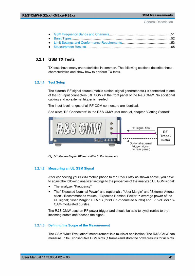
GSM MeasurementsR&S®CMW-KG2xx/-KM2xx/-KS2xx
41User Manual 1173.9634.02 ─ 06
● GSM Frequency Bands and Channels....................................................................51● Burst Types.............................................................................................................52● Limit Settings and Conformance Requirements......................................................53● Measurement Results.............................................................................................65
3.2.1 GSM TX Tests
TX tests have many characteristics in common. The following sections describe thesecharacteristics and show how to perform TX tests.
3.2.1.1 Test Setup
The external RF signal source (mobile station, signal generator etc.) is connected to oneof the RF input connectors (RF COM) at the front panel of the R&S CMW. No additionalcabling and no external trigger is needed.
The input level ranges of all RF COM connectors are identical.
See also: "RF Connectors" in the R&S CMW user manual, chapter "Getting Started"
Fig. 3-1: Connecting an RF transmitter to the instrument
3.2.1.2 Measuring an UL GSM Signal
After connecting your GSM mobile phone to the R&S CMW as shown above, you haveto adjust the following analyzer settings to the properties of the analyzed UL GSM signal:● The analyzer "Frequency"● The "Expected Nominal Power" and (optional) a "User Margin" and "External Attenu-
ation". Recommended values: "Expected Nominal Power" = average power of theUE signal; "User Margin" = + 5 dB (for 8PSK-modulated bursts) and +7.5 dB (for 16-QAM-modulated bursts).
The R&S CMW uses an RF power trigger and should be able to synchronize to theincoming bursts and decode the signal.
3.2.1.3 Defining the Scope of the Measurement
The GSM "Multi Evaluation" measurement is a multislot application: The R&S CMW canmeasure up to 8 consecutive GSM slots (1 frame) and store the power results for all slots.
General Description
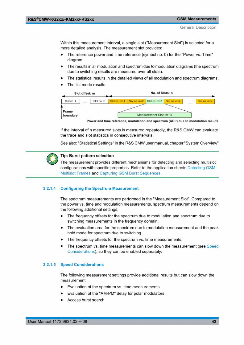
GSM MeasurementsR&S®CMW-KG2xx/-KM2xx/-KS2xx
42User Manual 1173.9634.02 ─ 06
Within this measurement interval, a single slot ("Measurement Slot") is selected for amore detailed analysis. The measurement slot provides:● The reference power and time reference (symbol no. 0) for the "Power vs. Time"
diagram.● The results in all modulation and spectrum due to modulation diagrams (the spectrum
due to switching results are measured over all slots).● The statistical results in the detailed views of all modulation and spectrum diagrams.● The list mode results.
If the interval of n measured slots is measured repeatedly, the R&S CMW can evaluatethe trace and slot statistics in consecutive intervals.
See also: "Statistical Settings" in the R&S CMW user manual, chapter "System Overview"
Tip: Burst pattern selectionThe measurement provides different mechanisms for detecting and selecting multislotconfigurations with specific properties. Refer to the application sheets Detecting GSMMultislot Frames and Capturing GSM Burst Sequences.
3.2.1.4 Configuring the Spectrum Measurement
The spectrum measurements are performed in the "Measurement Slot". Compared tothe power vs. time and modulation measurements, spectrum measurements depend onthe following additional settings:● The frequency offsets for the spectrum due to modulation and spectrum due to
switching measurements in the frequency domain.● The evaluation area for the spectrum due to modulation measurement and the peak
hold mode for spectrum due to switching.● The frequency offsets for the spectrum vs. time measurements.● The spectrum vs. time measurements can slow down the measurement (see Speed
Considerations), so they can be enabled separately.
3.2.1.5 Speed Considerations
The following measurement settings provide additional results but can slow down themeasurement:● Evaluation of the spectrum vs. time measurements● Evaluation of the "AM-PM" delay for polar modulators● Access burst search
General Description
GSM MeasurementsR&S®CMW-KG2xx/-KM2xx/-KS2xx
43User Manual 1173.9634.02 ─ 06
The following settings improve the accuracy of the results but require additional process-ing time:● Measurement of 8PSK or 16-QAM-modulated bursts in "Data Compensated" refer-
ence power mode.
3.2.1.6 Trigger Settings
The GSM multi evaluation measurement can be performed in "Free Run" (untriggered)mode, however, an internal trigger is suitable for most measurement tasks.
Note the following Trigger Source settings:● With a "Power" trigger, the measurement is triggered by the power ramp of the
received GSM bursts. Use this trigger source for single-slot measurements and forunique events such as the access burst transmitted during the connection setup.
● With an "Acquisition" trigger, the R&S CMW analyzes the RF input signal and derivesa frame trigger using information about the active slots. Use this trigger source formultislot measurements, in particular those with repeated burst patterns.
Refer also to the application sheet Detecting GSM Multislot Frames.
3.2.2 GSM RX Tests
RX tests can be carried out in parallel to the GSM TX Tests. This section describes theprinciple of the GSM Bit Error Rate (BER) measurement.
The R&S CMW uses either the ARB generator or the GSM real-time generator to senda bit pattern to the receiver of the mobile under test. The mobile must loop back thereceived bits. The "GSM Multi Evaluation" measurement can compare the looped-backbit pattern with the original pattern in order to calculate the BER.
The R&S CMW supports two different BER measurements for GMSK and 8PSK-modu-lated signals, respectively. For each measurement, the configuration of the mobile, theARB or real-time generator, and the measurement must match.
The two ARB files for GSM BER measurements provide signals with the following prop-erties:● File LoopC_1040.wv provides a GMSK-modulated, channel-coded full rate speech
TCH. The raw bit pattern is an alternating 010101... sequence, however, the signalis channel-coded so that the transferred bit sequence is approximately random.Channel coding means that the mobile can measure the channel quality, thereforeyou may compare the RxQual values with the BER measured by the R&S CMW. EachGMSK-modulated normal burst carries 114 data bits to be compared for the BERmeasurement.
● File SRB_8PSK_1040.wv provides an 8PSK-modulated signal. Only the header ischannel-coded, the transferred data bit sequence is approximately random. With thissignal, the R&S CMW can perform BER tests for modulation and coding schemesMCS7, MCS8, and MCS9.
General Description
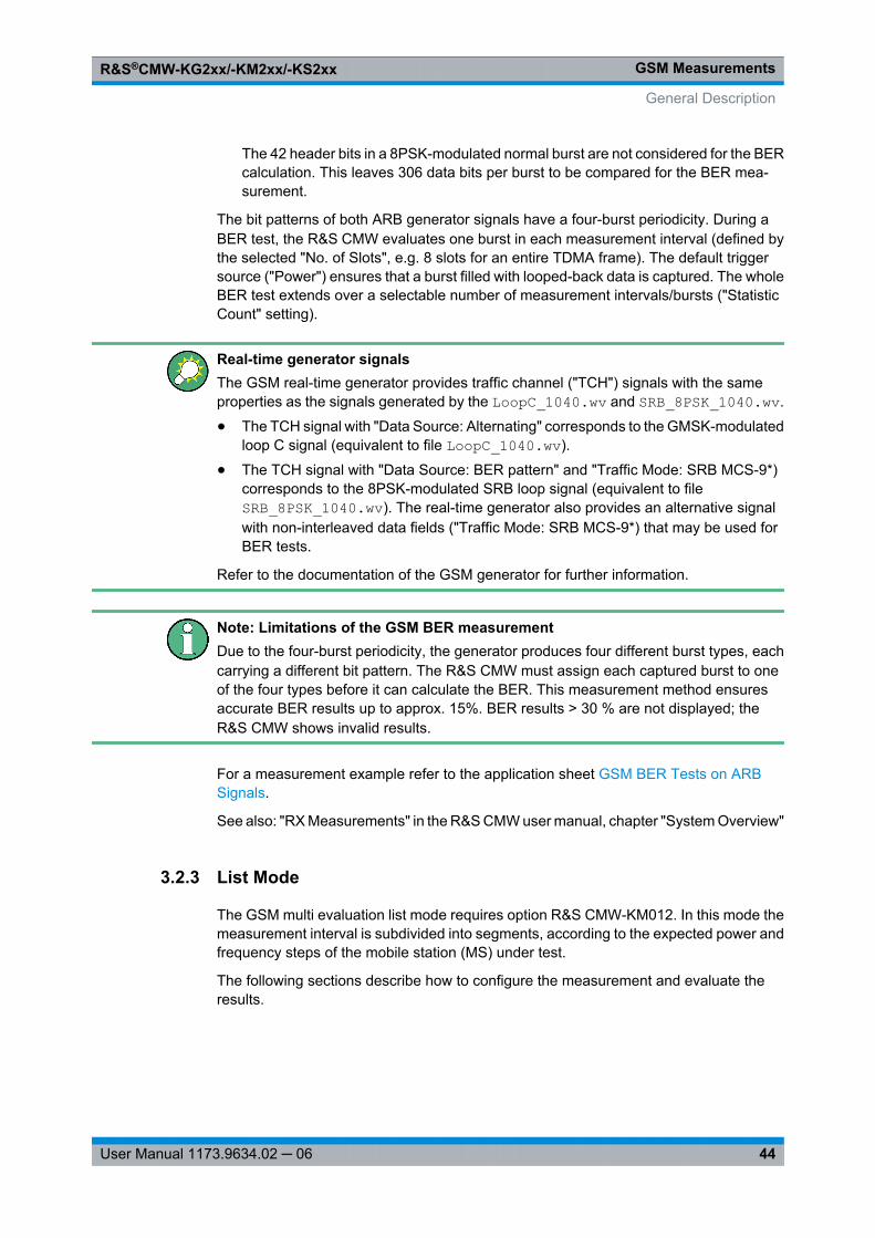
GSM MeasurementsR&S®CMW-KG2xx/-KM2xx/-KS2xx
44User Manual 1173.9634.02 ─ 06
The 42 header bits in a 8PSK-modulated normal burst are not considered for the BERcalculation. This leaves 306 data bits per burst to be compared for the BER mea-surement.
The bit patterns of both ARB generator signals have a four-burst periodicity. During aBER test, the R&S CMW evaluates one burst in each measurement interval (defined bythe selected "No. of Slots", e.g. 8 slots for an entire TDMA frame). The default triggersource ("Power") ensures that a burst filled with looped-back data is captured. The wholeBER test extends over a selectable number of measurement intervals/bursts ("StatisticCount" setting).
Real-time generator signalsThe GSM real-time generator provides traffic channel ("TCH") signals with the sameproperties as the signals generated by the LoopC_1040.wv and SRB_8PSK_1040.wv.
● The TCH signal with "Data Source: Alternating" corresponds to the GMSK-modulatedloop C signal (equivalent to file LoopC_1040.wv).
● The TCH signal with "Data Source: BER pattern" and "Traffic Mode: SRB MCS-9*)corresponds to the 8PSK-modulated SRB loop signal (equivalent to fileSRB_8PSK_1040.wv). The real-time generator also provides an alternative signalwith non-interleaved data fields ("Traffic Mode: SRB MCS-9*) that may be used forBER tests.
Refer to the documentation of the GSM generator for further information.
Note: Limitations of the GSM BER measurementDue to the four-burst periodicity, the generator produces four different burst types, eachcarrying a different bit pattern. The R&S CMW must assign each captured burst to oneof the four types before it can calculate the BER. This measurement method ensuresaccurate BER results up to approx. 15%. BER results > 30 % are not displayed; theR&S CMW shows invalid results.
For a measurement example refer to the application sheet GSM BER Tests on ARBSignals.
See also: "RX Measurements" in the R&S CMW user manual, chapter "System Overview"
3.2.3 List Mode
The GSM multi evaluation list mode requires option R&S CMW-KM012. In this mode themeasurement interval is subdivided into segments, according to the expected power andfrequency steps of the mobile station (MS) under test.
The following sections describe how to configure the measurement and evaluate theresults.
General Description

GSM MeasurementsR&S®CMW-KG2xx/-KM2xx/-KS2xx
45User Manual 1173.9634.02 ─ 06
● List Mode Configuration..........................................................................................45● Extension for Multislot Measurements....................................................................48● Conditions and Restrictions....................................................................................49● Offline Mode and Offline Segment..........................................................................49
3.2.3.1 List Mode Configuration
Each segment contains an integer number of timeslots and is measured at constantanalyzer settings (i.e. at constant expected nominal power and RF frequency). The figurebelow shows a series of four segments with different lengths. Orange bars depict mea-sured timeslots.
The standard application of the GSM list mode is to measure a range of equidistant time-slots separated by gaps. The distance between 2 measured timeslots ("step length") canvary between 1 and 8 timeslots (1 TDMA frame). The relationship between the steplength, measured steps per segment and segment length is shown below. The figureshows four measured, active slots (orange). The remaining slots may be active or inac-tive; they are not measured. With a step length of 4 slots, segment no. 1 contains 3measured steps and has a duration of 12 timeslots (1.5 TDMA frames).
An "evaluation offset" excludes an integer number of timeslots at the beginning of eachsegment from the measurement.
In list mode the R&S CMW can measure all power, modulation, spectrum due to modu-lation, and spectrum due to switching results. It is possible to enable or disable the mea-sured quantities individually for each segment. Moreover, it is possible to define a stat-istical length for the calculation of average, minimum, and maximum results.
General Description
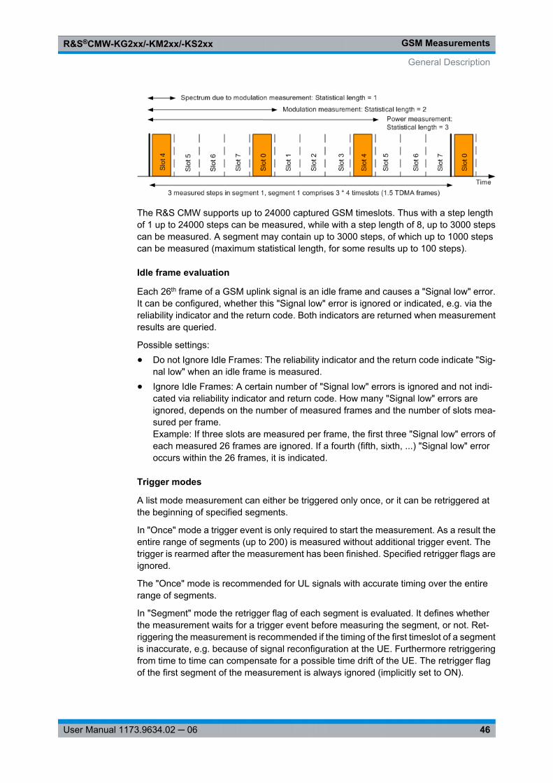
GSM MeasurementsR&S®CMW-KG2xx/-KM2xx/-KS2xx
46User Manual 1173.9634.02 ─ 06
The R&S CMW supports up to 24000 captured GSM timeslots. Thus with a step lengthof 1 up to 24000 steps can be measured, while with a step length of 8, up to 3000 stepscan be measured. A segment may contain up to 3000 steps, of which up to 1000 stepscan be measured (maximum statistical length, for some results up to 100 steps).
Idle frame evaluation
Each 26th frame of a GSM uplink signal is an idle frame and causes a "Signal low" error.It can be configured, whether this "Signal low" error is ignored or indicated, e.g. via thereliability indicator and the return code. Both indicators are returned when measurementresults are queried.
Possible settings:● Do not Ignore Idle Frames: The reliability indicator and the return code indicate "Sig-
nal low" when an idle frame is measured.● Ignore Idle Frames: A certain number of "Signal low" errors is ignored and not indi-
cated via reliability indicator and return code. How many "Signal low" errors areignored, depends on the number of measured frames and the number of slots mea-sured per frame.Example: If three slots are measured per frame, the first three "Signal low" errors ofeach measured 26 frames are ignored. If a fourth (fifth, sixth, ...) "Signal low" erroroccurs within the 26 frames, it is indicated.
Trigger modes
A list mode measurement can either be triggered only once, or it can be retriggered atthe beginning of specified segments.
In "Once" mode a trigger event is only required to start the measurement. As a result theentire range of segments (up to 200) is measured without additional trigger event. Thetrigger is rearmed after the measurement has been finished. Specified retrigger flags areignored.
The "Once" mode is recommended for UL signals with accurate timing over the entirerange of segments.
In "Segment" mode the retrigger flag of each segment is evaluated. It defines whetherthe measurement waits for a trigger event before measuring the segment, or not. Ret-riggering the measurement is recommended if the timing of the first timeslot of a segmentis inaccurate, e.g. because of signal reconfiguration at the UE. Furthermore retriggeringfrom time to time can compensate for a possible time drift of the UE. The retrigger flagof the first segment of the measurement is always ignored (implicitly set to ON).
General Description
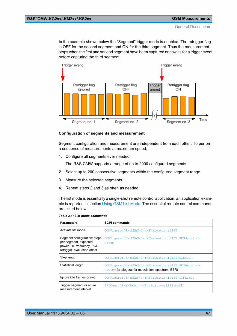
GSM MeasurementsR&S®CMW-KG2xx/-KM2xx/-KS2xx
47User Manual 1173.9634.02 ─ 06
In the example shown below the "Segment" trigger mode is enabled. The retrigger flagis OFF for the second segment and ON for the third segment. Thus the measurementstops when the first and second segment have been captured and waits for a trigger eventbefore capturing the third segment.
Configuration of segments and measurement
Segment configuration and measurement are independent from each other. To performa sequence of measurements at maximum speed,
1. Configure all segments ever needed.
The R&S CMW supports a range of up to 2000 configured segments.
2. Select up to 200 consecutive segments within the configured segment range.
3. Measure the selected segments.
4. Repeat steps 2 and 3 as often as needed.
The list mode is essentially a single-shot remote control application; an application exam-ple is reported in section Using GSM List Mode. The essential remote control commandsare listed below.
Table 3-1: List mode commands
Parameters SCPI commands
Activate list mode CONFigure: GSM: MEAS<i>: MEValuation: LIST
Segment configuration: stepsper segment, expectedpower, RF frequency, PCL,retrigger, evaluation offset
CONFigure: GSM: MEAS<i>: MEValuation: LIST: SEGMent<no>: SETup
Step length CONFigure: GSM: MEAS<i>: MEValuation: LIST: SLENgth
Statistical length CONFigure: GSM: MEAS<i>: MEValuation: LIST: SEGMent<no>: PVTime (analogous for modulation, spectrum, BER)
Ignore idle frames or not CONFigure: GSM: MEAS<i>: MEValuation: LIST: IIFRames
Trigger segment or entiremeasurement interval
TRIGger: GSM: MEAS<i>: MEValuation: LIST: MODE
General Description

GSM MeasurementsR&S®CMW-KG2xx/-KM2xx/-KS2xx
48User Manual 1173.9634.02 ─ 06
Parameters SCPI commands
Select range of measuredsegments
CONFigure: GSM: MEAS<i>: MEValuation: LIST: LRANge
Retrieve results FETCh:GSM:MEAS<i>:MEValuation:LIST:SEGMent<no>:...FETCh:GSM:MEAS<i>:MEValuation:LIST:...See chapter 3.6.3.30, "List Mode Results (One Segment)", on page 205, chapter 3.6.3.32, "List Mode Results (All Segments, Result Groups)",on page 228 and chapter 3.6.3.31, "List Mode Results (All Segments, OneResult)", on page 215.
Note that the segment number <no> for configure commands is an absolutenumber (1..2000) while the segment number <no> for result retrieval is arelative number within the range of measured segments (1..200).
Example: Segment 1 to 100 configured. Segment 50 to 59 measured. Forresult retrieval <no> = 1 refers to segment 50, <no> = 10 to segment 59.
Global and list mode parametersThe RF settings (expected power, RF frequency) and most of the "Measurement Control"settings (step length, steps per segment, averaging lengths, enable/disable results) arespecial list mode settings. The R&S CMW ignores the corresponding "multi evaluation"parameters. All other settings are taken from the multi evaluation measurement, e.g.:● Measure on Exception● Slot Offset, Number of Slots, Measurement Slot: always use the *RST values (0, 1,
0) for list mode measurements● Access Burst Search● Special "Power", "Modulation", "Spectrum Modulation", and "Spectrum Switching"
settings● All trigger settings (note that an "Acquisition" trigger cannot be used in list mode)● All limit settings
3.2.3.2 Extension for Multislot Measurements
In principle, the list mode is compatible with any MS signal configuration. For multislotconfigurations, a special "frame pattern" mode is available. In this mode, the R&S CMWcan measure an arbitrary number of (not necessarily equidistant) slots per 8-slot period.The first 8-slot period starts with the trigger event; it does not have to coincide with theTDMA frame boundary of the measured GSM signal.
General Description
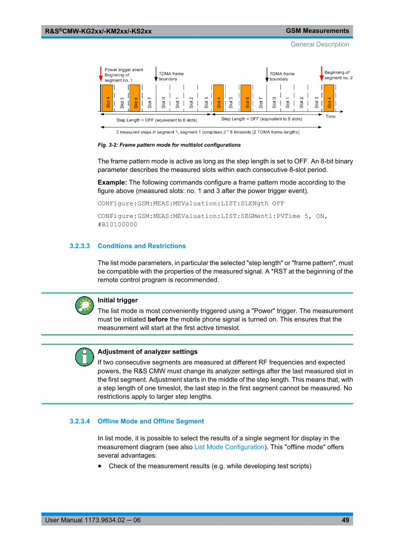
GSM MeasurementsR&S®CMW-KG2xx/-KM2xx/-KS2xx
49User Manual 1173.9634.02 ─ 06
Fig. 3-2: Frame pattern mode for multislot configurations
The frame pattern mode is active as long as the step length is set to OFF. An 8-bit binaryparameter describes the measured slots within each consecutive 8-slot period.
Example: The following commands configure a frame pattern mode according to thefigure above (measured slots: no. 1 and 3 after the power trigger event).
CONFigure:GSM:MEAS:MEValuation:LIST:SLENgth OFFCONFigure:GSM:MEAS:MEValuation:LIST:SEGMent1:PVTime 5, ON,#B10100000
3.2.3.3 Conditions and Restrictions
The list mode parameters, in particular the selected "step length" or "frame pattern", mustbe compatible with the properties of the measured signal. A *RST at the beginning of theremote control program is recommended.
Initial triggerThe list mode is most conveniently triggered using a "Power" trigger. The measurementmust be initiated before the mobile phone signal is turned on. This ensures that themeasurement will start at the first active timeslot.
Adjustment of analyzer settingsIf two consecutive segments are measured at different RF frequencies and expectedpowers, the R&S CMW must change its analyzer settings after the last measured slot inthe first segment. Adjustment starts in the middle of the step length. This means that, witha step length of one timeslot, the last step in the first segment cannot be measured. Norestrictions apply to larger step lengths.
3.2.3.4 Offline Mode and Offline Segment
In list mode, it is possible to select the results of a single segment for display in themeasurement diagram (see also List Mode Configuration). This "offline mode" offersseveral advantages:● Check of the measurement results (e.g. while developing test scripts)
General Description
GSM MeasurementsR&S®CMW-KG2xx/-KM2xx/-KS2xx
50User Manual 1173.9634.02 ─ 06
● Calculation and display of additional measurement results (traces). Use theFETCh:GSM:MEAS:MEValuation:TRACe:... commands to retrieve theseresults.
After a list mode measurement is completed, the measurement diagram shows the lastsegment measured. Calculation of the offline results in an arbitrary segment requires atwo-stage measurement:
1. Start a single-shot list mode measurement (INITiate:GSM:MEAS:MEValuation)to collect all measurement data.
2. Select the offline segment(CONFigure:GSM:MEAS:MEValuation:LIST:OSINdex <Segment>), then ini-tiate a second measurement (repeat INITiate:GSM:MEAS:MEValuation) and goto local in order to view the results.
The second measurement stage implies a calculation of all measurement results in theoffline segment from the existing raw data; no new measurement data is acquired. Byrepeating this second stage for different segments, you can obtain a complete set ofmeasurement results over the entire measurement length.
Reconfiguration of the measurement, exampleTo obtain consistent results in the second measurement stage, the raw data must stillcorrespond to the measurement settings. Avoid any reconfiguration that would require anew measurement (e.g. a change of the step length), if you wish to re-use your data inoffline mode.For a measurement example see Using GSM List Mode.
3.2.4 GSM UL Signal Properties
The GSM physical channel uses a combination of frequency and time division multiplex-ing and is defined as a sequence of radio frequency channels and timeslots. The basicsystem and physical channel parameters are listed below.
Table 3-2: Basic GSM parameters
Parameter Value
TDMA frame duration 60/13 ms ≈ 4.615 ms
Slot duration (8 slots per TDMA frame) 15/26 ms ≈ 576.9 μs
Symbol rate 270.833 ksymbols/s
Symbol duration 3.69 μs/symbol
(--> 156.25 symbols per timeslot)
Modulation schemes GMSK (1 bit per symbol)
8PSK (3 bits per symbol)
16QAM (4 bits per symbol)
General Description
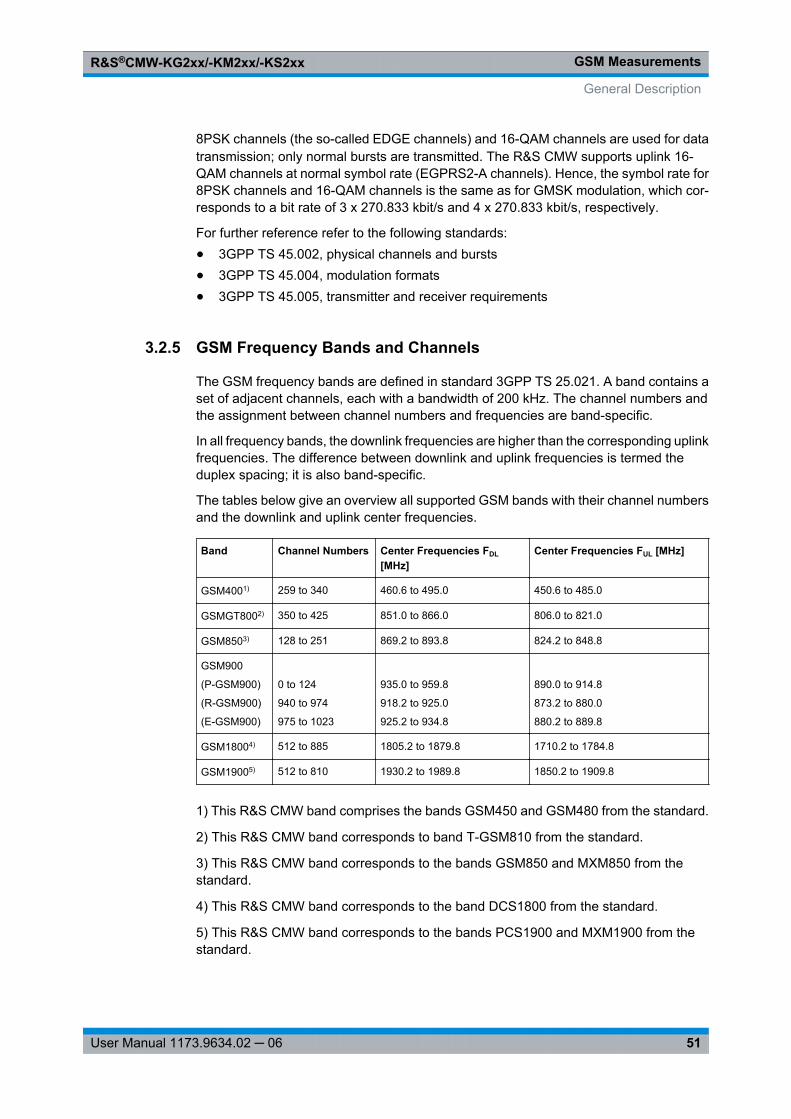
GSM MeasurementsR&S®CMW-KG2xx/-KM2xx/-KS2xx
51User Manual 1173.9634.02 ─ 06
8PSK channels (the so-called EDGE channels) and 16-QAM channels are used for datatransmission; only normal bursts are transmitted. The R&S CMW supports uplink 16-QAM channels at normal symbol rate (EGPRS2-A channels). Hence, the symbol rate for8PSK channels and 16-QAM channels is the same as for GMSK modulation, which cor-responds to a bit rate of 3 x 270.833 kbit/s and 4 x 270.833 kbit/s, respectively.
For further reference refer to the following standards:● 3GPP TS 45.002, physical channels and bursts● 3GPP TS 45.004, modulation formats● 3GPP TS 45.005, transmitter and receiver requirements
3.2.5 GSM Frequency Bands and Channels
The GSM frequency bands are defined in standard 3GPP TS 25.021. A band contains aset of adjacent channels, each with a bandwidth of 200 kHz. The channel numbers andthe assignment between channel numbers and frequencies are band-specific.
In all frequency bands, the downlink frequencies are higher than the corresponding uplinkfrequencies. The difference between downlink and uplink frequencies is termed theduplex spacing; it is also band-specific.
The tables below give an overview all supported GSM bands with their channel numbersand the downlink and uplink center frequencies.
Band Channel Numbers Center Frequencies FDL
[MHz]Center Frequencies FUL [MHz]
GSM4001) 259 to 340 460.6 to 495.0 450.6 to 485.0
GSMGT8002) 350 to 425 851.0 to 866.0 806.0 to 821.0
GSM8503) 128 to 251 869.2 to 893.8 824.2 to 848.8
GSM900
(P-GSM900)
(R-GSM900)
(E-GSM900)
0 to 124
940 to 974
975 to 1023
935.0 to 959.8
918.2 to 925.0
925.2 to 934.8
890.0 to 914.8
873.2 to 880.0
880.2 to 889.8
GSM18004) 512 to 885 1805.2 to 1879.8 1710.2 to 1784.8
GSM19005) 512 to 810 1930.2 to 1989.8 1850.2 to 1909.8
1) This R&S CMW band comprises the bands GSM450 and GSM480 from the standard.
2) This R&S CMW band corresponds to band T-GSM810 from the standard.
3) This R&S CMW band corresponds to the bands GSM850 and MXM850 from thestandard.
4) This R&S CMW band corresponds to the band DCS1800 from the standard.
5) This R&S CMW band corresponds to the bands PCS1900 and MXM1900 from thestandard.
General Description
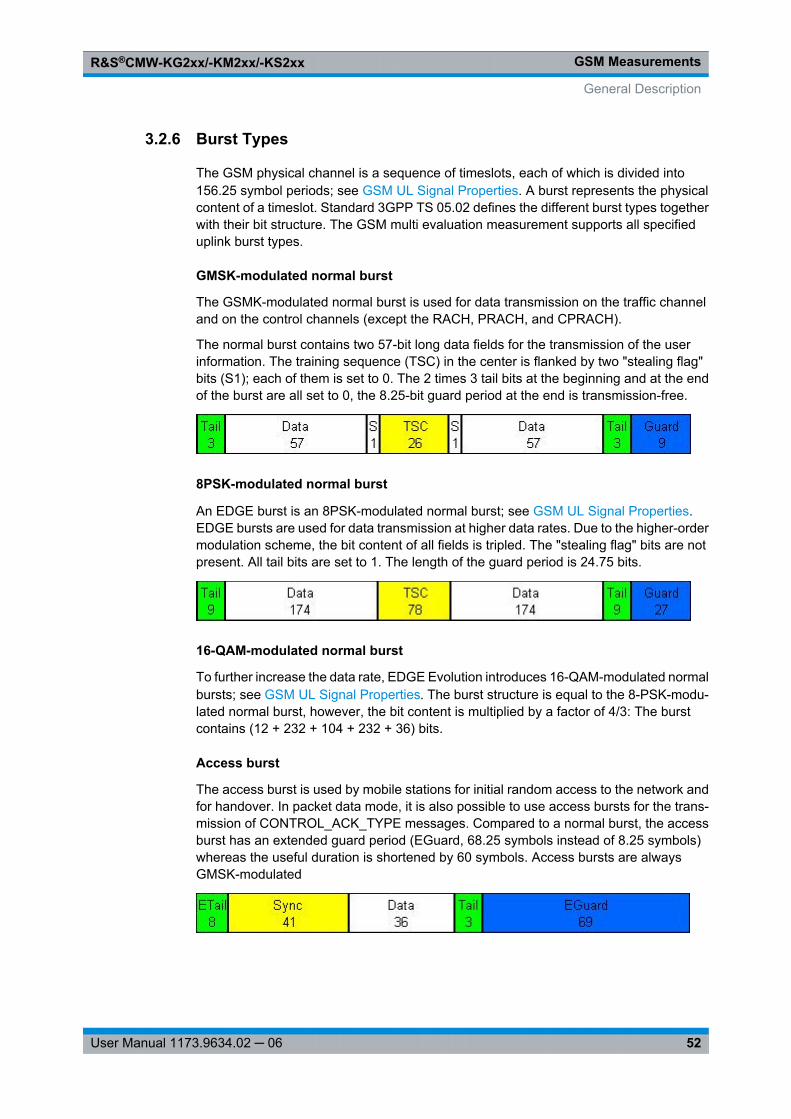
GSM MeasurementsR&S®CMW-KG2xx/-KM2xx/-KS2xx
52User Manual 1173.9634.02 ─ 06
3.2.6 Burst Types
The GSM physical channel is a sequence of timeslots, each of which is divided into156.25 symbol periods; see GSM UL Signal Properties. A burst represents the physicalcontent of a timeslot. Standard 3GPP TS 05.02 defines the different burst types togetherwith their bit structure. The GSM multi evaluation measurement supports all specifieduplink burst types.
GMSK-modulated normal burst
The GSMK-modulated normal burst is used for data transmission on the traffic channeland on the control channels (except the RACH, PRACH, and CPRACH).
The normal burst contains two 57-bit long data fields for the transmission of the userinformation. The training sequence (TSC) in the center is flanked by two "stealing flag"bits (S1); each of them is set to 0. The 2 times 3 tail bits at the beginning and at the endof the burst are all set to 0, the 8.25-bit guard period at the end is transmission-free.
8PSK-modulated normal burst
An EDGE burst is an 8PSK-modulated normal burst; see GSM UL Signal Properties.EDGE bursts are used for data transmission at higher data rates. Due to the higher-ordermodulation scheme, the bit content of all fields is tripled. The "stealing flag" bits are notpresent. All tail bits are set to 1. The length of the guard period is 24.75 bits.
16-QAM-modulated normal burst
To further increase the data rate, EDGE Evolution introduces 16-QAM-modulated normalbursts; see GSM UL Signal Properties. The burst structure is equal to the 8-PSK-modu-lated normal burst, however, the bit content is multiplied by a factor of 4/3: The burstcontains (12 + 232 + 104 + 232 + 36) bits.
Access burst
The access burst is used by mobile stations for initial random access to the network andfor handover. In packet data mode, it is also possible to use access bursts for the trans-mission of CONTROL_ACK_TYPE messages. Compared to a normal burst, the accessburst has an extended guard period (EGuard, 68.25 symbols instead of 8.25 symbols)whereas the useful duration is shortened by 60 symbols. Access bursts are alwaysGMSK-modulated
General Description
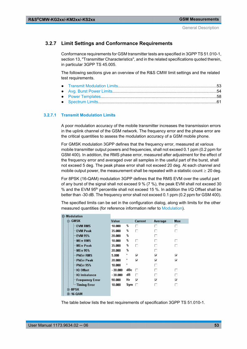
GSM MeasurementsR&S®CMW-KG2xx/-KM2xx/-KS2xx
53User Manual 1173.9634.02 ─ 06
3.2.7 Limit Settings and Conformance Requirements
Conformance requirements for GSM transmitter tests are specified in 3GPP TS 51.010-1,section 13, "Transmitter Characteristics", and in the related specifications quoted therein,in particular 3GPP TS 45.005.
The following sections give an overview of the R&S CMW limit settings and the relatedtest requirements.
● Transmit Modulation Limits.....................................................................................53● Avg. Burst Power Limits..........................................................................................54● Power Templates....................................................................................................58● Spectrum Limits......................................................................................................61
3.2.7.1 Transmit Modulation Limits
A poor modulation accuracy of the mobile transmitter increases the transmission errorsin the uplink channel of the GSM network. The frequency error and the phase error arethe critical quantities to assess the modulation accuracy of a GSM mobile phone.
For GMSK modulation 3GPP defines that the frequency error, measured at variousmobile transmitter output powers and frequencies, shall not exceed 0.1 ppm (0.2 ppm forGSM 400). In addition, the RMS phase error, measured after adjustment for the effect ofthe frequency error and averaged over all samples in the useful part of the burst, shallnot exceed 5 deg. The peak phase error shall not exceed 20 deg. At each channel andmobile output power, the measurement shall be repeated with a statistic count ≥ 20 deg.
For 8PSK (16-QAM) modulation 3GPP defines that the RMS EVM over the useful partof any burst of the signal shall not exceed 9 % (7 %), the peak EVM shall not exceed 30% and the EVM 95th percentile shall not exceed 15 %. In addition the I/Q Offset shall bebetter than -30 dB. The frequency error shall not exceed 0.1 ppm (0.2 ppm for GSM 400).
The specified limits can be set in the configuration dialog, along with limits for the othermeasured quantities (for reference information refer to Modulation).
The table below lists the test requirements of specification 3GPP TS 51.010-1.
General Description
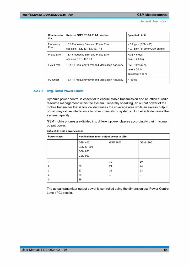
GSM MeasurementsR&S®CMW-KG2xx/-KM2xx/-KS2xx
54User Manual 1173.9634.02 ─ 06
Characteris-tics
Refer to 3GPP TS 51.010-1, section... Specified Limit
FrequencyError
13.1 Frequency Error and Phase Error
see also: 13.6, 13.16.1, 13.17.1
< 0.2 ppm (GSM 400)
< 0.1 ppm (all other GSM bands)
Phase Error 13.1 Frequency Error and Phase Error
see also: 13.6, 13.16.1
RMS < 5 deg
peak < 20 deg
EVM Error 13.17.1 Frequency Error and Modulation Accuracy RMS < 9 % (7 %)
peak < 30 %
percentile < 15 %
I/Q Offset 13.17.1 Frequency Error and Modulation Accuracy > -30 dB
3.2.7.2 Avg. Burst Power Limits
Dynamic power control is essential to ensure stable transmission and an efficient radioresource management within the system. Generally speaking, an output power of themobile transmitter that is too low decreases the coverage area while an excess outputpower may cause interference to other channels or systems. Both effects decrease thesystem capacity.
GSM mobile phones are divided into different power classes according to their maximumoutput power.
Table 3-3: GSM power classes
Power class Nominal maximum output power in dBm
GSM 400
GSM GT800
GSM 850
GSM 900
GSM 1800 GSM 1900
1
2
3
4
5
–
39
37
33
29
30
24
36
–
–
30
24
33
–
–
The actual transmitter output power is controlled using the dimensionless Power ControlLevel (PCL) scale.
General Description
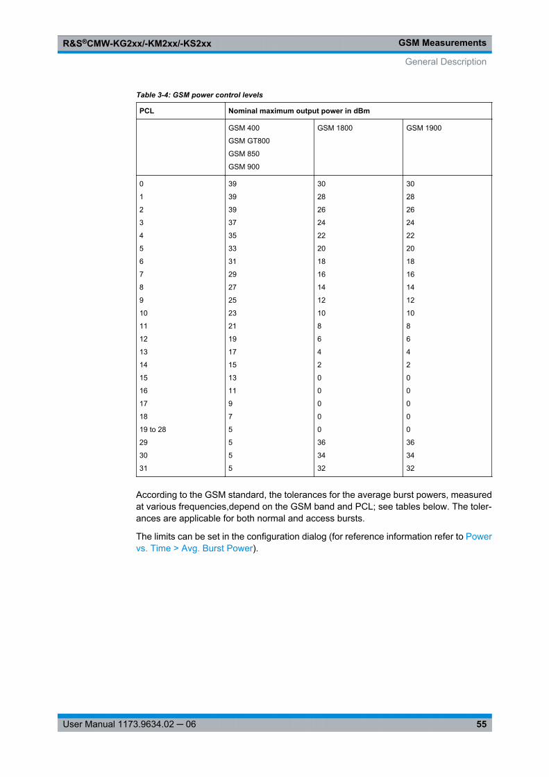
GSM MeasurementsR&S®CMW-KG2xx/-KM2xx/-KS2xx
55User Manual 1173.9634.02 ─ 06
Table 3-4: GSM power control levels
PCL Nominal maximum output power in dBm
GSM 400
GSM GT800
GSM 850
GSM 900
GSM 1800 GSM 1900
0
1
2
3
4
5
6
7
8
9
10
11
12
13
14
15
16
17
18
19 to 28
29
30
31
39
39
39
37
35
33
31
29
27
25
23
21
19
17
15
13
11
9
7
5
5
5
5
30
28
26
24
22
20
18
16
14
12
10
8
6
4
2
0
0
0
0
0
36
34
32
30
28
26
24
22
20
18
16
14
12
10
8
6
4
2
0
0
0
0
0
36
34
32
According to the GSM standard, the tolerances for the average burst powers, measuredat various frequencies,depend on the GSM band and PCL; see tables below. The toler-ances are applicable for both normal and access bursts.
The limits can be set in the configuration dialog (for reference information refer to Powervs. Time > Avg. Burst Power).
General Description
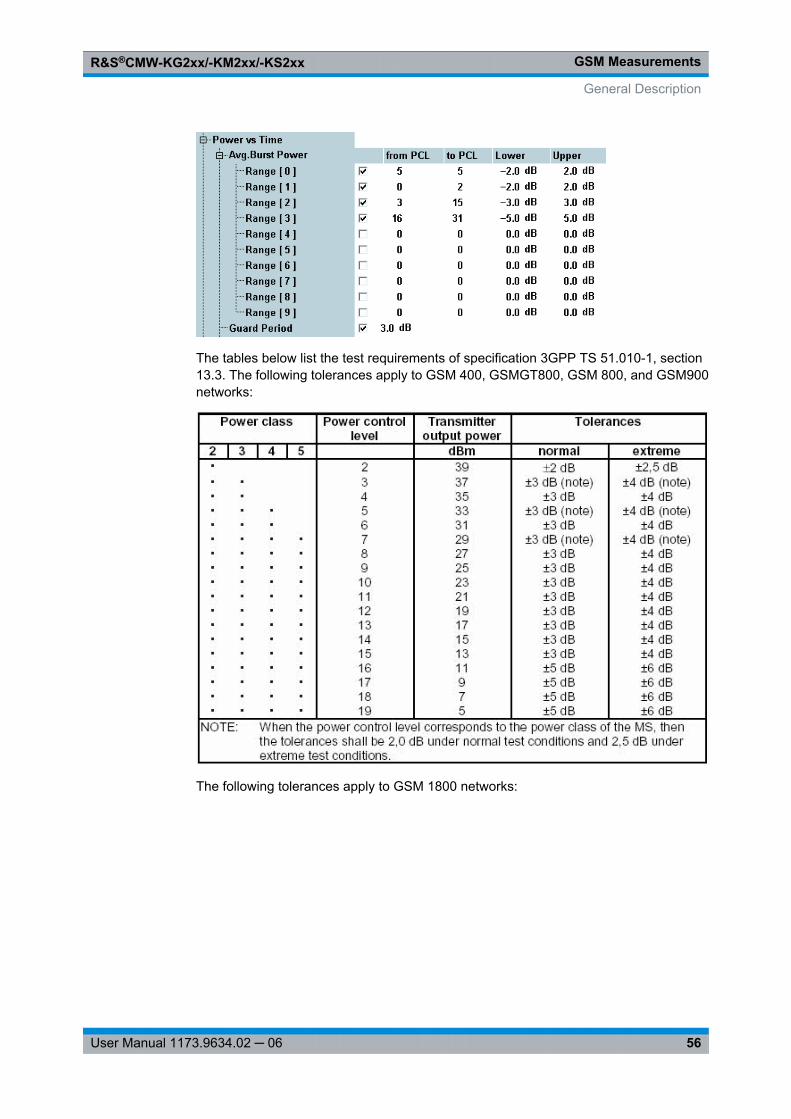
GSM MeasurementsR&S®CMW-KG2xx/-KM2xx/-KS2xx
56User Manual 1173.9634.02 ─ 06
The tables below list the test requirements of specification 3GPP TS 51.010-1, section13.3. The following tolerances apply to GSM 400, GSMGT800, GSM 800, and GSM900networks:
The following tolerances apply to GSM 1800 networks:
General Description
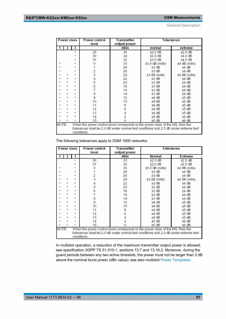
GSM MeasurementsR&S®CMW-KG2xx/-KM2xx/-KS2xx
57User Manual 1173.9634.02 ─ 06
The following tolerances apply to GSM 1900 networks:
In multislot operation, a reduction of the maximum transmitter output power is allowed;see specification 3GPP TS 51.010-1, sections 13.7 and 13.16.2. Moreover, during theguard periods between any two active timeslots, the power must not be larger than 3 dBabove the nominal burst power (dBc value); see also multislot Power Templates.
General Description
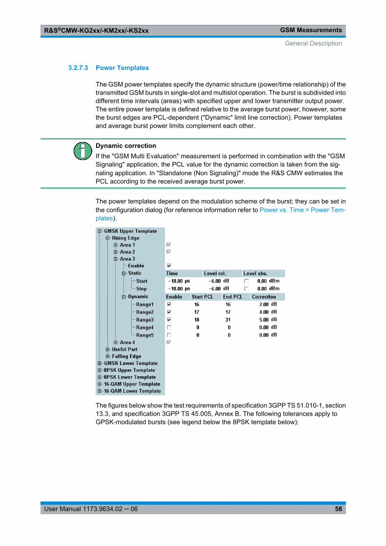
GSM MeasurementsR&S®CMW-KG2xx/-KM2xx/-KS2xx
58User Manual 1173.9634.02 ─ 06
3.2.7.3 Power Templates
The GSM power templates specify the dynamic structure (power/time relationship) of thetransmitted GSM bursts in single-slot and multislot operation. The burst is subdivided intodifferent time intervals (areas) with specified upper and lower transmitter output power.The entire power template is defined relative to the average burst power, however, somethe burst edges are PCL-dependent ("Dynamic" limit line correction). Power templatesand average burst power limits complement each other.
Dynamic correctionIf the "GSM Multi Evaluation" measurement is performed in combination with the "GSMSignaling" application, the PCL value for the dynamic correction is taken from the sig-naling application. In "Standalone (Non Signaling)" mode the R&S CMW estimates thePCL according to the received average burst power.
The power templates depend on the modulation scheme of the burst; they can be set inthe configuration dialog (for reference information refer to Power vs. Time > Power Tem-plates).
The figures below show the test requirements of specification 3GPP TS 51.010-1, section13.3, and specification 3GPP TS 45.005, Annex B. The following tolerances apply toGPSK-modulated bursts (see legend below the 8PSK template below):
General Description
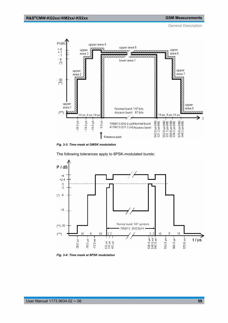
GSM MeasurementsR&S®CMW-KG2xx/-KM2xx/-KS2xx
59User Manual 1173.9634.02 ─ 06
Fig. 3-3: Time mask at GMSK modulation
The following tolerances apply to 8PSK-modulated bursts:
Fig. 3-4: Time mask at 8PSK modulation
General Description
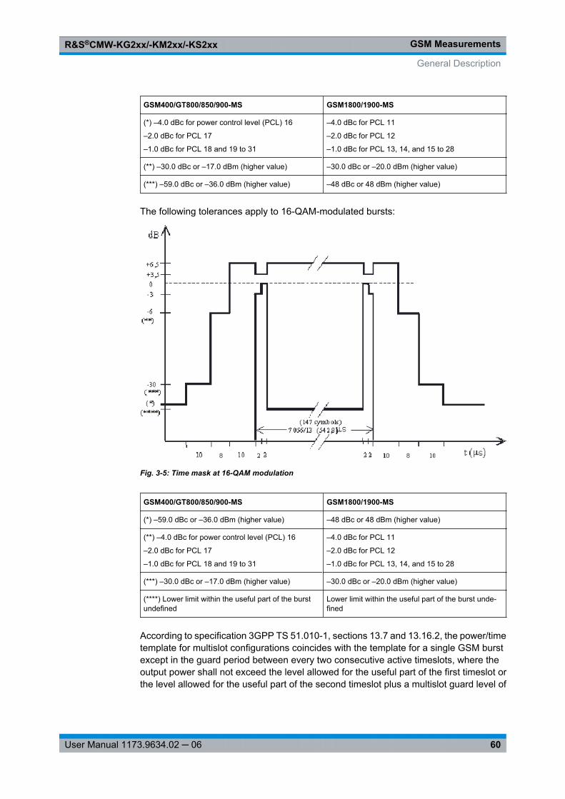
GSM MeasurementsR&S®CMW-KG2xx/-KM2xx/-KS2xx
60User Manual 1173.9634.02 ─ 06
GSM400/GT800/850/900-MS GSM1800/1900-MS
(*) –4.0 dBc for power control level (PCL) 16
–2.0 dBc for PCL 17
–1.0 dBc for PCL 18 and 19 to 31
–4.0 dBc for PCL 11
–2.0 dBc for PCL 12
–1.0 dBc for PCL 13, 14, and 15 to 28
(**) –30.0 dBc or –17.0 dBm (higher value) –30.0 dBc or –20.0 dBm (higher value)
(***) –59.0 dBc or –36.0 dBm (higher value) –48 dBc or 48 dBm (higher value)
The following tolerances apply to 16-QAM-modulated bursts:
Fig. 3-5: Time mask at 16-QAM modulation
GSM400/GT800/850/900-MS GSM1800/1900-MS
(*) –59.0 dBc or –36.0 dBm (higher value) –48 dBc or 48 dBm (higher value)
(**) –4.0 dBc for power control level (PCL) 16
–2.0 dBc for PCL 17
–1.0 dBc for PCL 18 and 19 to 31
–4.0 dBc for PCL 11
–2.0 dBc for PCL 12
–1.0 dBc for PCL 13, 14, and 15 to 28
(***) –30.0 dBc or –17.0 dBm (higher value) –30.0 dBc or –20.0 dBm (higher value)
(****) Lower limit within the useful part of the burstundefined
Lower limit within the useful part of the burst unde-fined
According to specification 3GPP TS 51.010-1, sections 13.7 and 13.16.2, the power/timetemplate for multislot configurations coincides with the template for a single GSM burstexcept in the guard period between every two consecutive active timeslots, where theoutput power shall not exceed the level allowed for the useful part of the first timeslot orthe level allowed for the useful part of the second timeslot plus a multislot guard level of
General Description
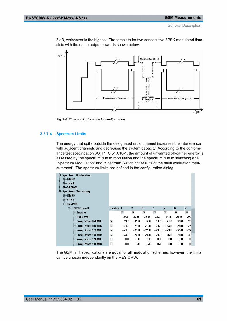
GSM MeasurementsR&S®CMW-KG2xx/-KM2xx/-KS2xx
61User Manual 1173.9634.02 ─ 06
3 dB, whichever is the highest. The template for two consecutive 8PSK modulated time-slots with the same output power is shown below.
Fig. 3-6: Time mask of a multislot configuration
3.2.7.4 Spectrum Limits
The energy that spills outside the designated radio channel increases the interferencewith adjacent channels and decreases the system capacity. According to the conform-ance test specification 3GPP TS 51.010-1, the amount of unwanted off-carrier energy isassessed by the spectrum due to modulation and the spectrum due to switching (the"Spectrum Modulation" and "Spectrum Switching" results of the multi evaluation mea-surement). The spectrum limits are defined in the configuration dialog.
The GSM limit specifications are equal for all modulation schemes, however, the limitscan be chosen independently on the R&S CMW.
General Description
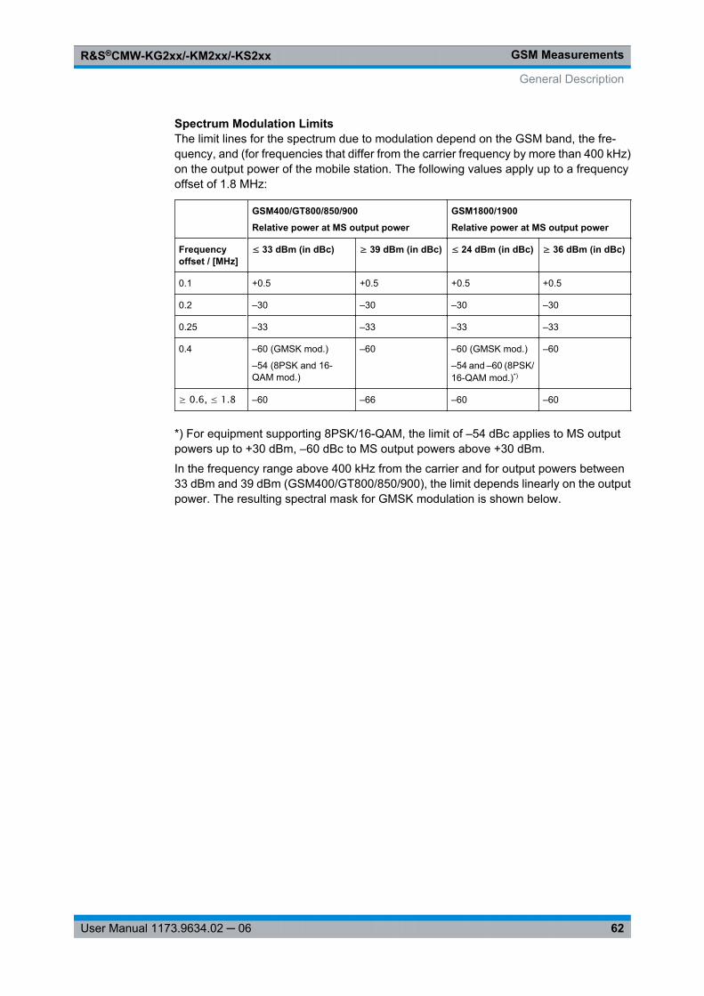
GSM MeasurementsR&S®CMW-KG2xx/-KM2xx/-KS2xx
62User Manual 1173.9634.02 ─ 06
Spectrum Modulation LimitsThe limit lines for the spectrum due to modulation depend on the GSM band, the fre-quency, and (for frequencies that differ from the carrier frequency by more than 400 kHz)on the output power of the mobile station. The following values apply up to a frequencyoffset of 1.8 MHz:
GSM400/GT800/850/900
Relative power at MS output power
GSM1800/1900
Relative power at MS output power
Frequencyoffset / [MHz]
≤ 33 dBm (in dBc) ≥ 39 dBm (in dBc) ≤ 24 dBm (in dBc) ≥ 36 dBm (in dBc)
0.1 +0.5 +0.5 +0.5 +0.5
0.2 –30 –30 –30 –30
0.25 –33 –33 –33 –33
0.4 –60 (GMSK mod.)
–54 (8PSK and 16-QAM mod.)
–60 –60 (GMSK mod.)
–54 and –60 (8PSK/16-QAM mod.)*)
–60
≥ 0.6, ≤ 1.8 –60 –66 –60 –60
*) For equipment supporting 8PSK/16-QAM, the limit of –54 dBc applies to MS outputpowers up to +30 dBm, –60 dBc to MS output powers above +30 dBm.
In the frequency range above 400 kHz from the carrier and for output powers between33 dBm and 39 dBm (GSM400/GT800/850/900), the limit depends linearly on the outputpower. The resulting spectral mask for GMSK modulation is shown below.
General Description
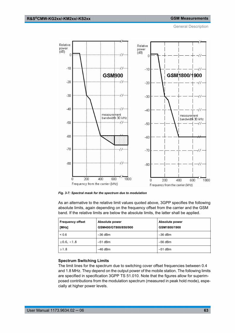
GSM MeasurementsR&S®CMW-KG2xx/-KM2xx/-KS2xx
63User Manual 1173.9634.02 ─ 06
Fig. 3-7: Spectral mask for the spectrum due to modulation
As an alternative to the relative limit values quoted above, 3GPP specifies the followingabsolute limits, again depending on the frequency offset from the carrier and the GSMband. If the relative limits are below the absolute limits, the latter shall be applied.
Frequency offset
[MHz]
Absolute power
GSM400/GT800/850/900
Absolute power
GSM1800/1900
< 0.6 –36 dBm –36 dBm
≥0.6, <1.8 –51 dBm –56 dBm
≥1.8 –46 dBm –51 dBm
Spectrum Switching LimitsThe limit lines for the spectrum due to switching cover offset frequencies between 0.4and 1.8 MHz. They depend on the output power of the mobile station. The following limitsare specified in specification 3GPP TS 51.010. Note that the figures allow for superim-posed contributions from the modulation spectrum (measured in peak hold mode), espe-cially at higher power levels.
General Description
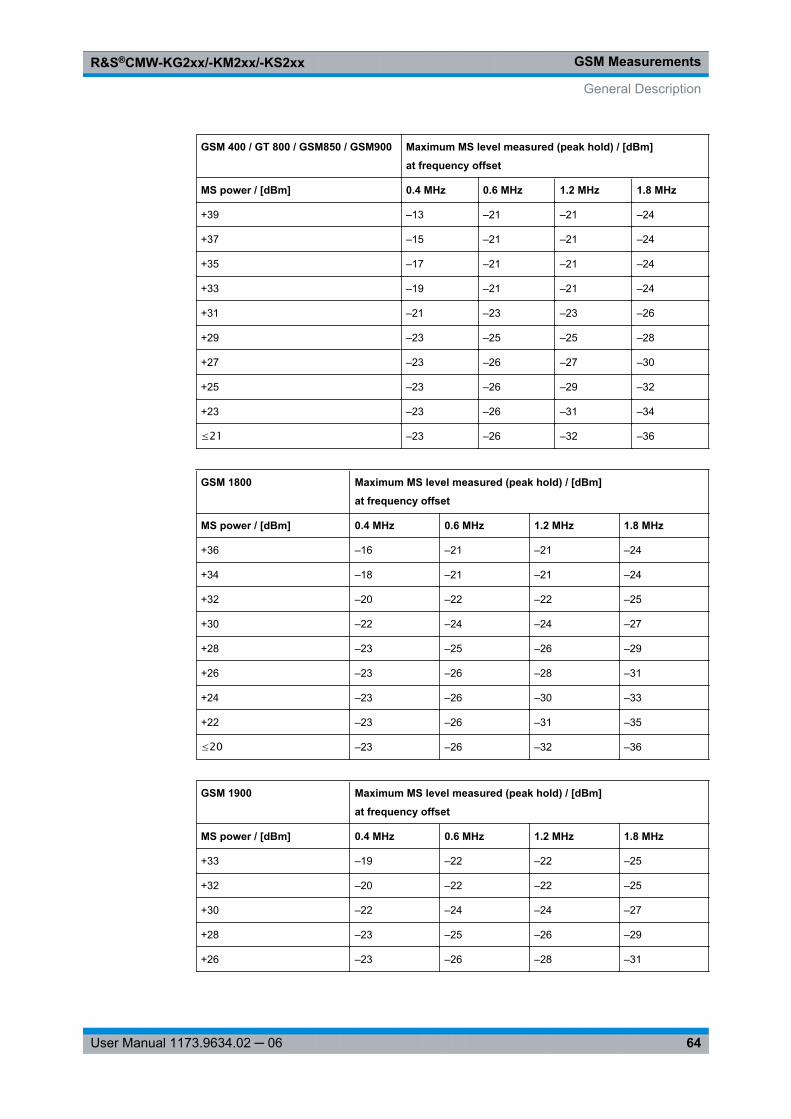
GSM MeasurementsR&S®CMW-KG2xx/-KM2xx/-KS2xx
64User Manual 1173.9634.02 ─ 06
GSM 400 / GT 800 / GSM850 / GSM900 Maximum MS level measured (peak hold) / [dBm]
at frequency offset
MS power / [dBm] 0.4 MHz 0.6 MHz 1.2 MHz 1.8 MHz
+39 –13 –21 –21 –24
+37 –15 –21 –21 –24
+35 –17 –21 –21 –24
+33 –19 –21 –21 –24
+31 –21 –23 –23 –26
+29 –23 –25 –25 –28
+27 –23 –26 –27 –30
+25 –23 –26 –29 –32
+23 –23 –26 –31 –34
≤21 –23 –26 –32 –36
GSM 1800 Maximum MS level measured (peak hold) / [dBm]
at frequency offset
MS power / [dBm] 0.4 MHz 0.6 MHz 1.2 MHz 1.8 MHz
+36 –16 –21 –21 –24
+34 –18 –21 –21 –24
+32 –20 –22 –22 –25
+30 –22 –24 –24 –27
+28 –23 –25 –26 –29
+26 –23 –26 –28 –31
+24 –23 –26 –30 –33
+22 –23 –26 –31 –35
≤20 –23 –26 –32 –36
GSM 1900 Maximum MS level measured (peak hold) / [dBm]
at frequency offset
MS power / [dBm] 0.4 MHz 0.6 MHz 1.2 MHz 1.8 MHz
+33 –19 –22 –22 –25
+32 –20 –22 –22 –25
+30 –22 –24 –24 –27
+28 –23 –25 –26 –29
+26 –23 –26 –28 –31
General Description
GSM MeasurementsR&S®CMW-KG2xx/-KM2xx/-KS2xx
65User Manual 1173.9634.02 ─ 06
GSM 1900 Maximum MS level measured (peak hold) / [dBm]
at frequency offset
MS power / [dBm] 0.4 MHz 0.6 MHz 1.2 MHz 1.8 MHz
+24 –23 –26 –30 –33
+22 –23 –26 –31 –35
≤20 –23 –26 –32 –36
3.2.8 Measurement Results
The results of the GSM multi evaluation measurement are displayed in several differentviews. Use the "Display" parameters to select the views and to change the appearanceand contents of the views. The views are described in the following sections.
● Overview.................................................................................................................65● Detailed Views: Modulation and Spectrum.............................................................66● Detailed Views: Power vs Time...............................................................................67● Detailed Views: IQ Constellation Diagram..............................................................69● Mod. Scalar and BER..............................................................................................70● Selecting and Modifying Views...............................................................................71● Using Markers.........................................................................................................72● Common View Elements.........................................................................................72
3.2.8.1 Overview
The overview dialog shows several or all of the detailed views in a single diagram.
General Description
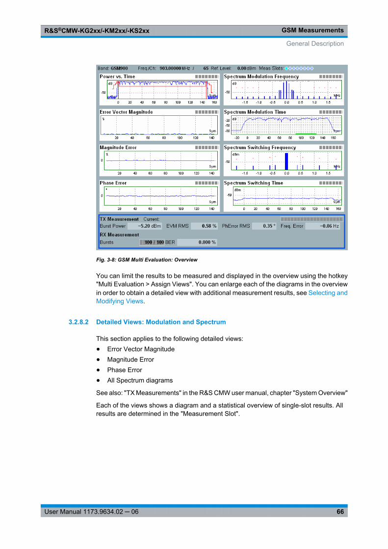
GSM MeasurementsR&S®CMW-KG2xx/-KM2xx/-KS2xx
66User Manual 1173.9634.02 ─ 06
Fig. 3-8: GSM Multi Evaluation: Overview
You can limit the results to be measured and displayed in the overview using the hotkey"Multi Evaluation > Assign Views". You can enlarge each of the diagrams in the overviewin order to obtain a detailed view with additional measurement results, see Selecting andModifying Views.
3.2.8.2 Detailed Views: Modulation and Spectrum
This section applies to the following detailed views:● Error Vector Magnitude● Magnitude Error● Phase Error● All Spectrum diagrams
See also: "TX Measurements" in the R&S CMW user manual, chapter "System Overview"
Each of the views shows a diagram and a statistical overview of single-slot results. Allresults are determined in the "Measurement Slot".
General Description
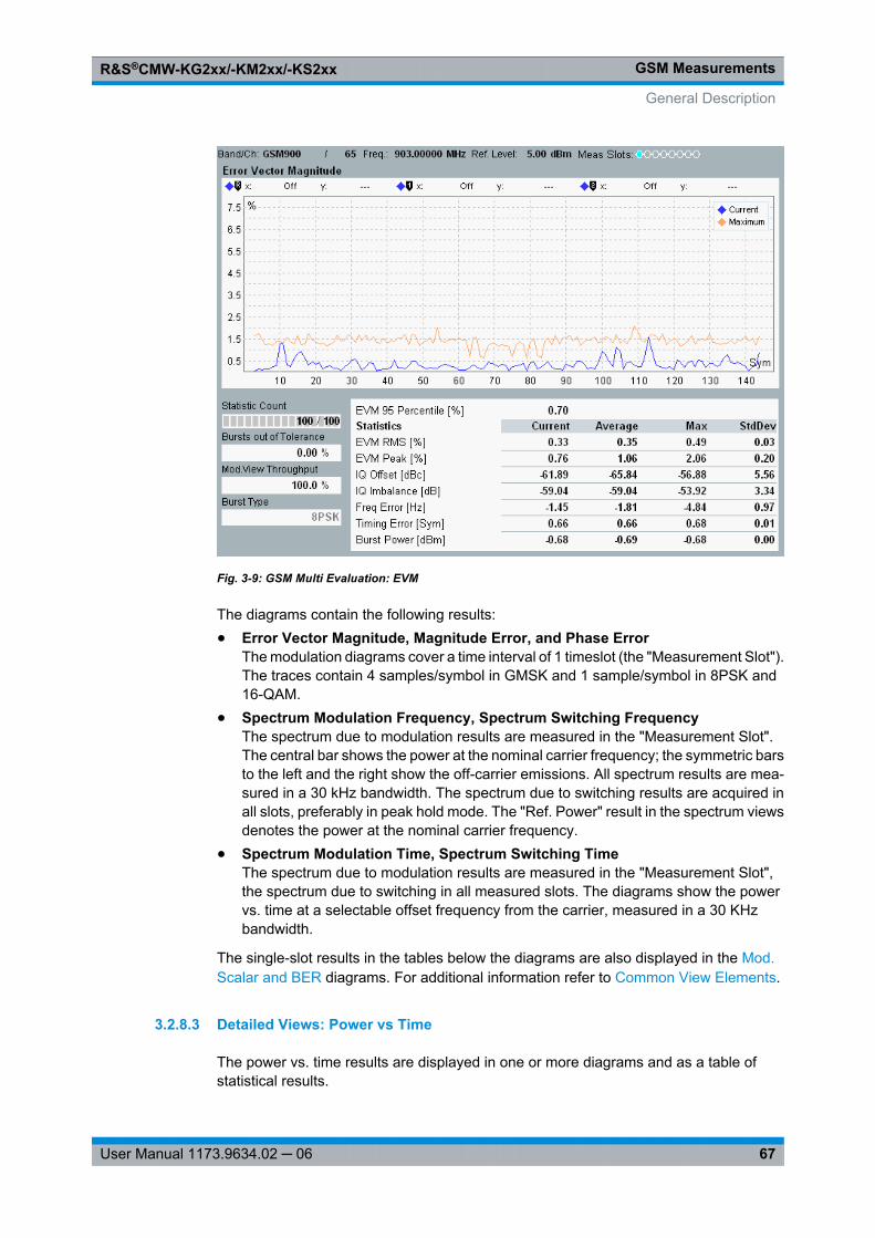
GSM MeasurementsR&S®CMW-KG2xx/-KM2xx/-KS2xx
67User Manual 1173.9634.02 ─ 06
Fig. 3-9: GSM Multi Evaluation: EVM
The diagrams contain the following results:● Error Vector Magnitude, Magnitude Error, and Phase Error
The modulation diagrams cover a time interval of 1 timeslot (the "Measurement Slot").The traces contain 4 samples/symbol in GMSK and 1 sample/symbol in 8PSK and16-QAM.
● Spectrum Modulation Frequency, Spectrum Switching FrequencyThe spectrum due to modulation results are measured in the "Measurement Slot".The central bar shows the power at the nominal carrier frequency; the symmetric barsto the left and the right show the off-carrier emissions. All spectrum results are mea-sured in a 30 kHz bandwidth. The spectrum due to switching results are acquired inall slots, preferably in peak hold mode. The "Ref. Power" result in the spectrum viewsdenotes the power at the nominal carrier frequency.
● Spectrum Modulation Time, Spectrum Switching TimeThe spectrum due to modulation results are measured in the "Measurement Slot",the spectrum due to switching in all measured slots. The diagrams show the powervs. time at a selectable offset frequency from the carrier, measured in a 30 KHzbandwidth.
The single-slot results in the tables below the diagrams are also displayed in the Mod.Scalar and BER diagrams. For additional information refer to Common View Elements.
3.2.8.3 Detailed Views: Power vs Time
The power vs. time results are displayed in one or more diagrams and as a table ofstatistical results.
General Description
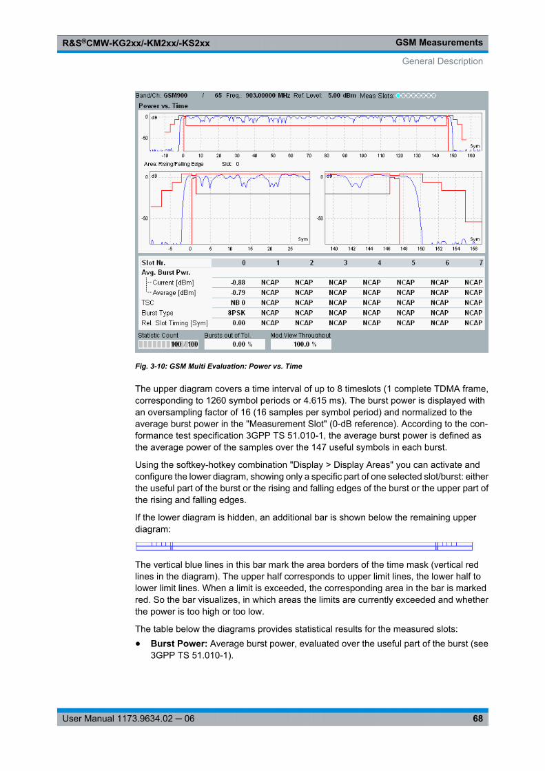
GSM MeasurementsR&S®CMW-KG2xx/-KM2xx/-KS2xx
68User Manual 1173.9634.02 ─ 06
Fig. 3-10: GSM Multi Evaluation: Power vs. Time
The upper diagram covers a time interval of up to 8 timeslots (1 complete TDMA frame,corresponding to 1260 symbol periods or 4.615 ms). The burst power is displayed withan oversampling factor of 16 (16 samples per symbol period) and normalized to theaverage burst power in the "Measurement Slot" (0-dB reference). According to the con-formance test specification 3GPP TS 51.010-1, the average burst power is defined asthe average power of the samples over the 147 useful symbols in each burst.
Using the softkey-hotkey combination "Display > Display Areas" you can activate andconfigure the lower diagram, showing only a specific part of one selected slot/burst: eitherthe useful part of the burst or the rising and falling edges of the burst or the upper part ofthe rising and falling edges.
If the lower diagram is hidden, an additional bar is shown below the remaining upperdiagram:
The vertical blue lines in this bar mark the area borders of the time mask (vertical redlines in the diagram). The upper half corresponds to upper limit lines, the lower half tolower limit lines. When a limit is exceeded, the corresponding area in the bar is markedred. So the bar visualizes, in which areas the limits are currently exceeded and whetherthe power is too high or too low.
The table below the diagrams provides statistical results for the measured slots:● Burst Power: Average burst power, evaluated over the useful part of the burst (see
3GPP TS 51.010-1).
General Description
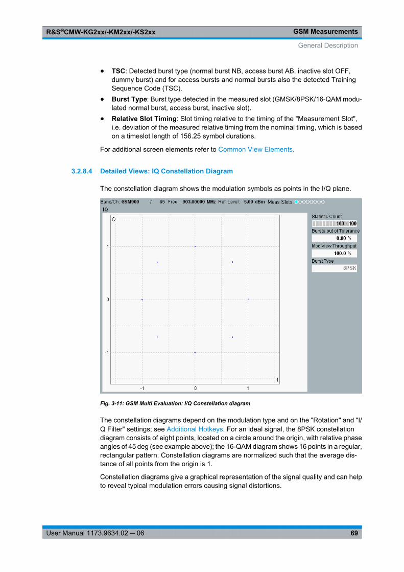
GSM MeasurementsR&S®CMW-KG2xx/-KM2xx/-KS2xx
69User Manual 1173.9634.02 ─ 06
● TSC: Detected burst type (normal burst NB, access burst AB, inactive slot OFF,dummy burst) and for access bursts and normal bursts also the detected TrainingSequence Code (TSC).
● Burst Type: Burst type detected in the measured slot (GMSK/8PSK/16-QAM modu-lated normal burst, access burst, inactive slot).
● Relative Slot Timing: Slot timing relative to the timing of the "Measurement Slot",i.e. deviation of the measured relative timing from the nominal timing, which is basedon a timeslot length of 156.25 symbol durations.
For additional screen elements refer to Common View Elements.
3.2.8.4 Detailed Views: IQ Constellation Diagram
The constellation diagram shows the modulation symbols as points in the I/Q plane.
Fig. 3-11: GSM Multi Evaluation: I/Q Constellation diagram
The constellation diagrams depend on the modulation type and on the "Rotation" and "I/Q Filter" settings; see Additional Hotkeys. For an ideal signal, the 8PSK constellationdiagram consists of eight points, located on a circle around the origin, with relative phaseangles of 45 deg (see example above); the 16-QAM diagram shows 16 points in a regular,rectangular pattern. Constellation diagrams are normalized such that the average dis-tance of all points from the origin is 1.
Constellation diagrams give a graphical representation of the signal quality and can helpto reveal typical modulation errors causing signal distortions.
General Description
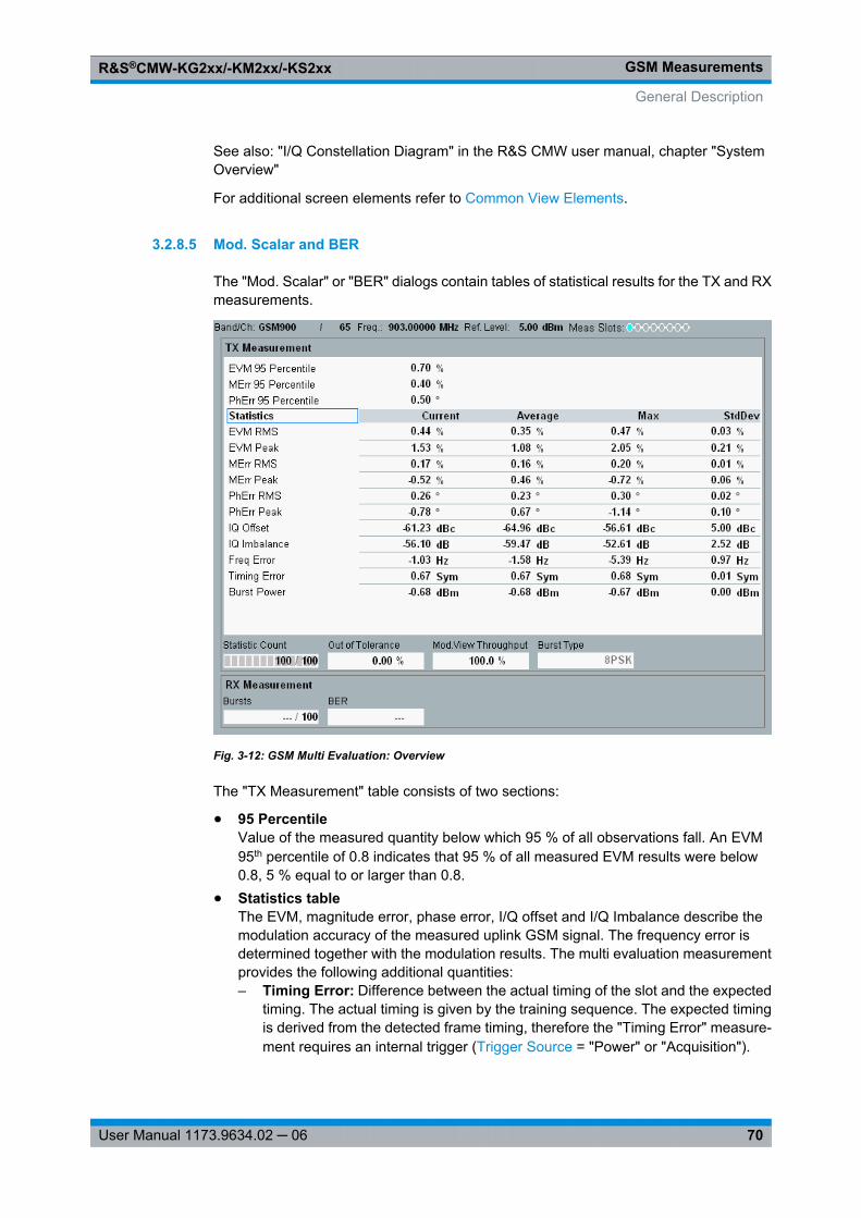
GSM MeasurementsR&S®CMW-KG2xx/-KM2xx/-KS2xx
70User Manual 1173.9634.02 ─ 06
See also: "I/Q Constellation Diagram" in the R&S CMW user manual, chapter "SystemOverview"
For additional screen elements refer to Common View Elements.
3.2.8.5 Mod. Scalar and BER
The "Mod. Scalar" or "BER" dialogs contain tables of statistical results for the TX and RXmeasurements.
Fig. 3-12: GSM Multi Evaluation: Overview
The "TX Measurement" table consists of two sections:
● 95 PercentileValue of the measured quantity below which 95 % of all observations fall. An EVM95th percentile of 0.8 indicates that 95 % of all measured EVM results were below0.8, 5 % equal to or larger than 0.8.
● Statistics tableThe EVM, magnitude error, phase error, I/Q offset and I/Q Imbalance describe themodulation accuracy of the measured uplink GSM signal. The frequency error isdetermined together with the modulation results. The multi evaluation measurementprovides the following additional quantities:– Timing Error: Difference between the actual timing of the slot and the expected
timing. The actual timing is given by the training sequence. The expected timingis derived from the detected frame timing, therefore the "Timing Error" measure-ment requires an internal trigger ( Trigger Source = "Power" or "Acquisition").
General Description
GSM MeasurementsR&S®CMW-KG2xx/-KM2xx/-KS2xx
71User Manual 1173.9634.02 ─ 06
– Burst Power: Average burst power, evaluated over the useful part of the burst(see 3GPP TS 51.010-1).
– AM PM Delay: Time delay of the amplitude vs. time trajectory of the basebandmodulation vector relative to the phase vs. time trajectory that is needed to min-imize the modulation errors (EVM). The AM PM delay is a characteristic quantityfor polar modulation schemes which make use of polar coordinates (amplitudeand phase) rather than Cartesian coordinates (I and Q amplitudes).
The "RX Measurement" panel displays the progress and result of the bit error ratetest, see GSM RX Tests.
● BurstsProgress bar of the measurement; see "Statistic Count" above.
● BERMeasured Bit Error Rate: The percentage of bits that the DUT received in error.
See also: "Modulation Accuracy" in the R&S CMW user manual, chapter "System Over-view"
For additional screen elements refer to Common View Elements.
3.2.8.6 Selecting and Modifying Views
Use the "Display" parameters to select the views and to change the appearance andcontents of the views. Depending on the selected view the following "Display" hotkeysare available:
Hotkey Description
"Select View ..." Switch to a certain detailed view or overview.
Alternatively select a diagram in the overview and press ENTER or the rotary knob.
"Select Trace ..." Select the trace types to be displayed in the view.
"X Scale... / YScale..."
Modify the ranges of the X-axis and the Y-axis.
"Display > TimeCurve"
In the "Spectrum Frequency" view: Change to the "Spectrum Time" diagram.
"Display > DemodBits"
In modulation views: Display a table with all demodulated bits of the "MeasurementSlot". The table contains one cell per symbol. An 8PSK (16-QAM) symbol correspondsto 3 (4) bits. The table can be used to analyze the correlation between modulation errorsand the transferred bit pattern.
"Display > DisplayAreas"
In the power vs time view: activate and configure an additional trace, showing a detailof the power vs time trace with enhanced resolution, e.g. the rising and falling edgesof one burst.
Additional options are available in the "Measurement Control" section of the configurationdialog.
General Description
GSM MeasurementsR&S®CMW-KG2xx/-KM2xx/-KS2xx
72User Manual 1173.9634.02 ─ 06
3.2.8.7 Using Markers
Use the "Marker" parameters to activate markers and to modify their position. The fol-lowing "Marker" hotkeys are available:
Hotkey Description
"Ref. Marker ..." Enable or disable the reference marker, select a trace and the marker position on thattrace
"Marker 1 /2 ..." Enable or disable marker 1 or 2 and define the marker position (absolute or relative tothe reference marker)
Depending on the trace mode, a trace can also be selected.
"Select TraceMode"
Define whether all markers are collectively set to the same trace or to individual traces
See also: "Markers" in the R&S CMW user manual, chapter "System Overview"
3.2.8.8 Common View Elements
Below the title bar, all views show the most important RF and analyzer settings as shownbelow.
For configuration see chapter 3.4.2.1, "Signal Routing and Analyzer Settings",on page 83.
Tables
The "Statistics" tables show a statistical evaluation in the measurement slot. They containfour columns. For each measurement result the values are calculated as follows:● Current: Value of the modulation result obtained in the last measurement interval.
For EVM, magnitude and phase error, a current RMS result (the average over allsamples in the "Measured Slot" except the guard period) and current peak value (thepeak of all samples the preselected slot except the guard period) is available.
● Average: Average of all "Current" values referenced to the last statistics cycle.● Max.: Largest or smallest "Current" value that the R&S CMW obtained since the start
of the measurement.● StdDev.: Standard deviation of all "Current" values since the start of the measure-
ment.
All statistical results (statistical tables and traces) are calculated according to the generalrules for statistical results.
See also: "Statistical Results" in the R&S CMW user manual, chapter "System Overview"
Statistic Count
Progress bar for the measurement. During the first single shot after the start of the mea-surement, the bar shows the current measurement interval relative to the "Statistic
General Description
GSM MeasurementsR&S®CMW-KG2xx/-KM2xx/-KS2xx
73User Manual 1173.9634.02 ─ 06
Count". A filled progress bar indicates that the first shot is complete and the statisticaldepth has been reached.
See also: "Statistical Settings" in the R&S CMW user manual, chapter "System Overview"
Out of Tolerance
Percentage of measurement intervals / bursts that were failed because they exceededthe limits in the diagram.
Mod. View Throughput
Percentage of measurement intervals where the detected burst pattern was found tocorrespond to the Modulation View settings. Only frames which contribute to the "Mod.View Throughput" are displayed, counted, and used for the statistical results; otherframes are rejected.
The "Mod. View Throughput" is evaluated in a moving window of 1000 frames. If a non-matching signal configuration is changed according to the "Modulation View" settings,the throughput increases linearly from 0 % to 100 %.
Burst Type
Burst type detected in the measured slot (GMSK/8PSK/16-QAM modulated normal burst,access burst, inactive slot).
3.3 Application Sheets
Application sheets describe short application examples for select issues and providerelated background information. The following application sheets are related to the "GSMMeasurements" firmware application.
● Detecting GSM Multislot Frames............................................................................73● Capturing GSM Burst Sequences...........................................................................75● Using GSM List Mode.............................................................................................78● GSM BER Tests on ARB Signals............................................................................80
3.3.1 Detecting GSM Multislot Frames
This application sheet describes the use of the R&S CMW trigger system for detectingand measuring GSM frames filled with a particular burst sequence. With appropriate trig-ger settings the R&S CMW can filter frames with the following properties:● Frames with several active timeslots but with 1 to 3 slot gap.● Frames with a particular pattern of inactive bursts and bursts of a definite modulation
scheme.
Application Sheets
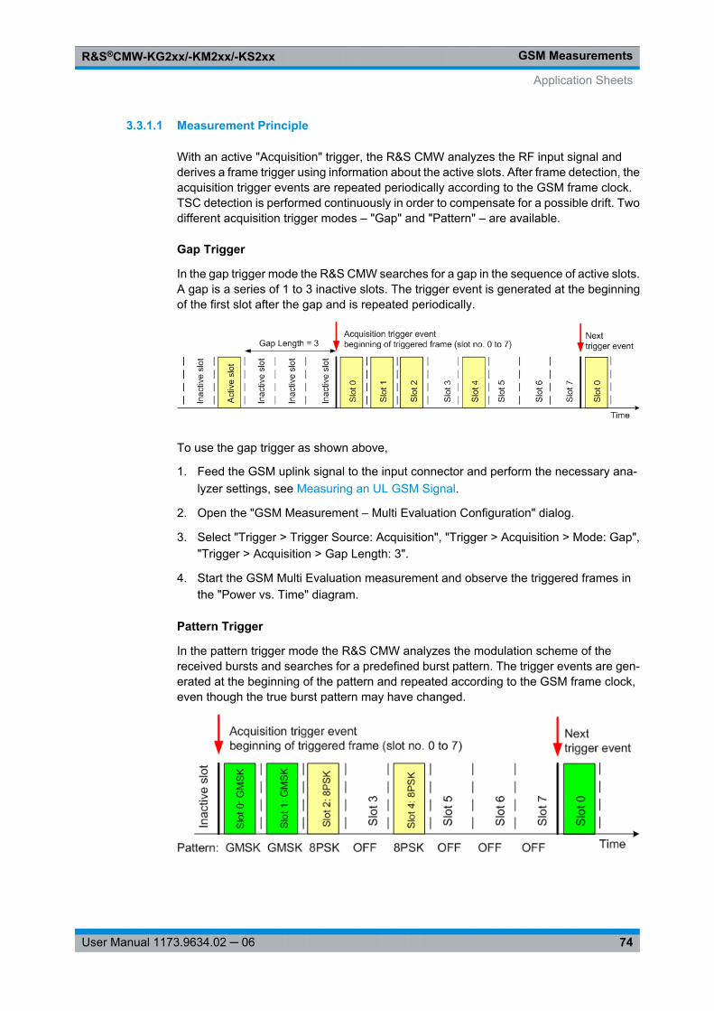
GSM MeasurementsR&S®CMW-KG2xx/-KM2xx/-KS2xx
74User Manual 1173.9634.02 ─ 06
3.3.1.1 Measurement Principle
With an active "Acquisition" trigger, the R&S CMW analyzes the RF input signal andderives a frame trigger using information about the active slots. After frame detection, theacquisition trigger events are repeated periodically according to the GSM frame clock.TSC detection is performed continuously in order to compensate for a possible drift. Twodifferent acquisition trigger modes – "Gap" and "Pattern" – are available.
Gap Trigger
In the gap trigger mode the R&S CMW searches for a gap in the sequence of active slots.A gap is a series of 1 to 3 inactive slots. The trigger event is generated at the beginningof the first slot after the gap and is repeated periodically.
To use the gap trigger as shown above,
1. Feed the GSM uplink signal to the input connector and perform the necessary ana-lyzer settings, see Measuring an UL GSM Signal.
2. Open the "GSM Measurement – Multi Evaluation Configuration" dialog.
3. Select "Trigger > Trigger Source: Acquisition", "Trigger > Acquisition > Mode: Gap","Trigger > Acquisition > Gap Length: 3".
4. Start the GSM Multi Evaluation measurement and observe the triggered frames inthe "Power vs. Time" diagram.
Pattern Trigger
In the pattern trigger mode the R&S CMW analyzes the modulation scheme of thereceived bursts and searches for a predefined burst pattern. The trigger events are gen-erated at the beginning of the pattern and repeated according to the GSM frame clock,even though the true burst pattern may have changed.
Application Sheets
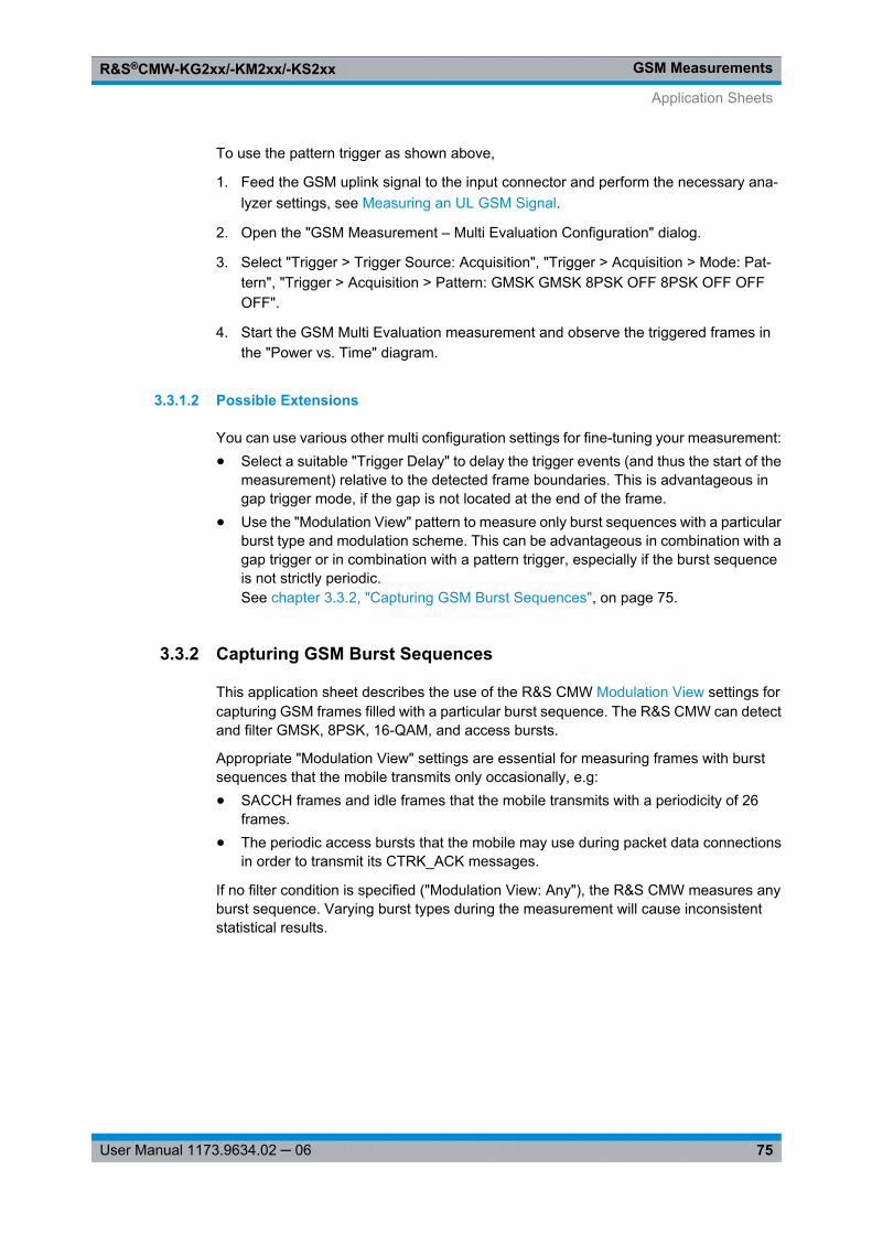
GSM MeasurementsR&S®CMW-KG2xx/-KM2xx/-KS2xx
75User Manual 1173.9634.02 ─ 06
To use the pattern trigger as shown above,
1. Feed the GSM uplink signal to the input connector and perform the necessary ana-lyzer settings, see Measuring an UL GSM Signal.
2. Open the "GSM Measurement – Multi Evaluation Configuration" dialog.
3. Select "Trigger > Trigger Source: Acquisition", "Trigger > Acquisition > Mode: Pat-tern", "Trigger > Acquisition > Pattern: GMSK GMSK 8PSK OFF 8PSK OFF OFFOFF".
4. Start the GSM Multi Evaluation measurement and observe the triggered frames inthe "Power vs. Time" diagram.
3.3.1.2 Possible Extensions
You can use various other multi configuration settings for fine-tuning your measurement:● Select a suitable "Trigger Delay" to delay the trigger events (and thus the start of the
measurement) relative to the detected frame boundaries. This is advantageous ingap trigger mode, if the gap is not located at the end of the frame.
● Use the "Modulation View" pattern to measure only burst sequences with a particularburst type and modulation scheme. This can be advantageous in combination with agap trigger or in combination with a pattern trigger, especially if the burst sequenceis not strictly periodic.See chapter 3.3.2, "Capturing GSM Burst Sequences", on page 75.
3.3.2 Capturing GSM Burst Sequences
This application sheet describes the use of the R&S CMW Modulation View settings forcapturing GSM frames filled with a particular burst sequence. The R&S CMW can detectand filter GMSK, 8PSK, 16-QAM, and access bursts.
Appropriate "Modulation View" settings are essential for measuring frames with burstsequences that the mobile transmits only occasionally, e.g:● SACCH frames and idle frames that the mobile transmits with a periodicity of 26
frames.● The periodic access bursts that the mobile may use during packet data connections
in order to transmit its CTRK_ACK messages.
If no filter condition is specified ("Modulation View: Any"), the R&S CMW measures anyburst sequence. Varying burst types during the measurement will cause inconsistentstatistical results.
Application Sheets
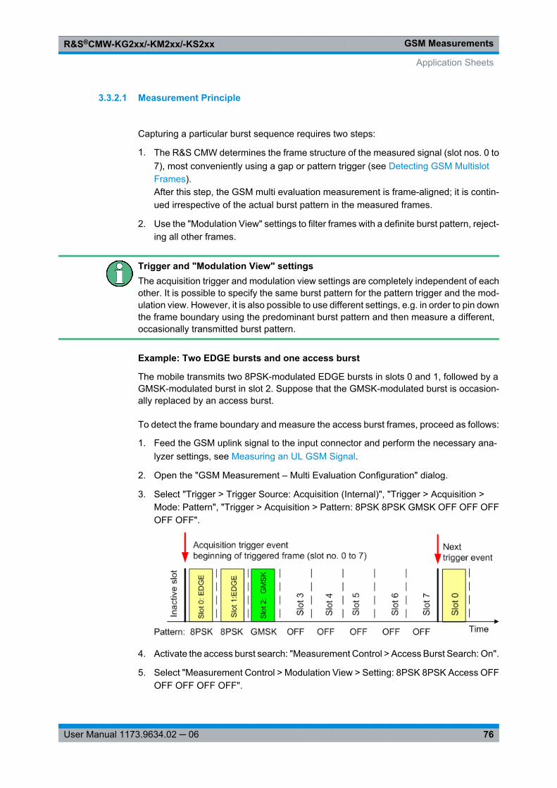
GSM MeasurementsR&S®CMW-KG2xx/-KM2xx/-KS2xx
76User Manual 1173.9634.02 ─ 06
3.3.2.1 Measurement Principle
Capturing a particular burst sequence requires two steps:
1. The R&S CMW determines the frame structure of the measured signal (slot nos. 0 to7), most conveniently using a gap or pattern trigger (see Detecting GSM MultislotFrames).After this step, the GSM multi evaluation measurement is frame-aligned; it is contin-ued irrespective of the actual burst pattern in the measured frames.
2. Use the "Modulation View" settings to filter frames with a definite burst pattern, reject-ing all other frames.
Trigger and "Modulation View" settingsThe acquisition trigger and modulation view settings are completely independent of eachother. It is possible to specify the same burst pattern for the pattern trigger and the mod-ulation view. However, it is also possible to use different settings, e.g. in order to pin downthe frame boundary using the predominant burst pattern and then measure a different,occasionally transmitted burst pattern.
Example: Two EDGE bursts and one access burst
The mobile transmits two 8PSK-modulated EDGE bursts in slots 0 and 1, followed by aGMSK-modulated burst in slot 2. Suppose that the GMSK-modulated burst is occasion-ally replaced by an access burst.
To detect the frame boundary and measure the access burst frames, proceed as follows:
1. Feed the GSM uplink signal to the input connector and perform the necessary ana-lyzer settings, see Measuring an UL GSM Signal.
2. Open the "GSM Measurement – Multi Evaluation Configuration" dialog.
3. Select "Trigger > Trigger Source: Acquisition (Internal)", "Trigger > Acquisition >Mode: Pattern", "Trigger > Acquisition > Pattern: 8PSK 8PSK GMSK OFF OFF OFFOFF OFF".
4. Activate the access burst search: "Measurement Control > Access Burst Search: On".
5. Select "Measurement Control > Modulation View > Setting: 8PSK 8PSK Access OFFOFF OFF OFF OFF".
Application Sheets
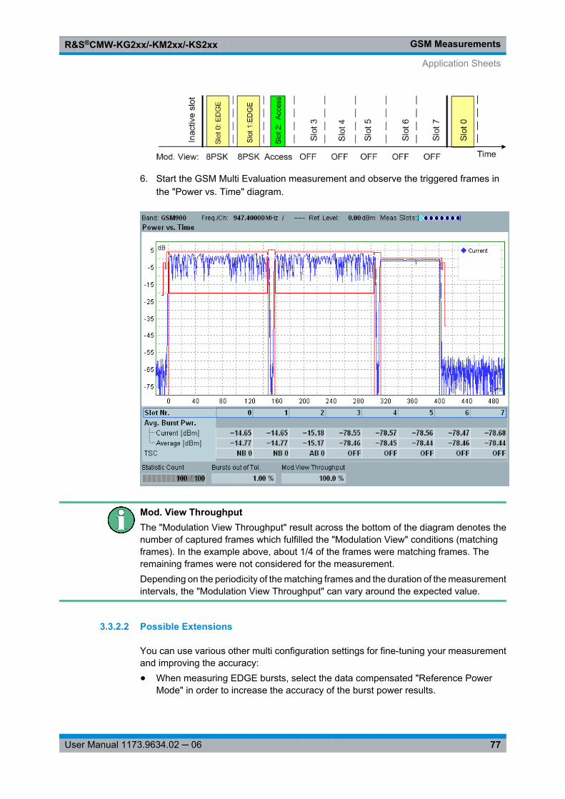
GSM MeasurementsR&S®CMW-KG2xx/-KM2xx/-KS2xx
77User Manual 1173.9634.02 ─ 06
6. Start the GSM Multi Evaluation measurement and observe the triggered frames inthe "Power vs. Time" diagram.
Mod. View ThroughputThe "Modulation View Throughput" result across the bottom of the diagram denotes thenumber of captured frames which fulfilled the "Modulation View" conditions (matchingframes). In the example above, about 1/4 of the frames were matching frames. Theremaining frames were not considered for the measurement.Depending on the periodicity of the matching frames and the duration of the measurementintervals, the "Modulation View Throughput" can vary around the expected value.
3.3.2.2 Possible Extensions
You can use various other multi configuration settings for fine-tuning your measurementand improving the accuracy:● When measuring EDGE bursts, select the data compensated "Reference Power
Mode" in order to increase the accuracy of the burst power results.
Application Sheets
GSM MeasurementsR&S®CMW-KG2xx/-KM2xx/-KS2xx
78User Manual 1173.9634.02 ─ 06
● Define an appropriate "Two Shot Assembly Level" to enhance the dynamic range.
3.3.3 Using GSM List Mode
This application sheet describes a GSM multi evaluation measurement in list mode,where the R&S CMW measures at a sequence of segments with individual analyzer set-tings. The measurement is essentially remote-controlled, however, you can switch tooffline mode in order to view results in a particular segment.
The measurement provides:● Average burst power, modulation, spectrum due to modulation, and spectrum due to
switching results in all segments. A BER measurement is supported in addition.● In addition, all measurement curves of the GSM multi evaluation measurement in any
of the measured segments (offline mode).
Initial triggerThe list mode is most conveniently triggered using a "Power" trigger. The measurementmust be initiated before the mobile phone signal is turned on. This ensures that themeasurement will start at the first active timeslot.
3.3.3.1 Options and Equipment Required
Analysis of an uplink GSM signal in multi evaluation list mode requires a R&S CMW testerwhich is equipped with the following options:● Option R&S CMW KM200, GSM TX Measurements● Option R&S CMW-KM012, Multi Evaluation List Mode
3.3.3.2 List Mode Configuration
In the following example an uplink GSM signal with the following properties is measured:● Measured Slot: Timeslot no. 0, timeslots 1 to 7 do not have to be analyzed● Burst type: Normal, 8PSK-modulated (EDGE burst)● Measurement duration: 120 slots (15 TDMA frames)● RF frequencies and powers, frames 1 to 5: 903.000 MHz, +5 dBm● RF frequencies and powers, frames 6 to 10: 947.000 MHz, +10 dBm● RF frequencies and powers, frames 11 to 15: 909.000 MHz, +15 dBm
1. According to the signal properties, configure a list mode with 3 segments using thefollowing command sequence:CONFigure:GSM:MEAS:MEValuation:LIST:SLENgth 8CONFigure:GSM:MEAS:MEValuation:LIST:SEGMent1:SETup 5, 10,9.03E+8, 19, ON, 0CONFigure:GSM:MEAS:MEValuation:LIST:SEGMent2:SETup 5, 15,9.47E+8, 17, OFF, 0
Application Sheets
GSM MeasurementsR&S®CMW-KG2xx/-KM2xx/-KS2xx
79User Manual 1173.9634.02 ─ 06
CONFigure:GSM:MEAS:MEValuation:LIST:SEGMent3:SETup 5, 20,9.09E+8, 14, OFF, 0
2. Enable the calculation of all power, modulation, spectrum due to modulation, andspectrum due to switching results in segment no. 1 and enable the list mode.CONFigure:GSM:MEAS:MEValuation:LIST:SEGMent1:PVTime 5, ON,#B10000000CONFigure:GSM:MEAS:MEValuation:LIST:SEGMent1:MODulation 5,ON, ON, ON, ON, #B10000000CONFigure:GSM:MEAS:MEValuation:LIST:SEGMent1:SMODulation 5,ON, #B10000000CONFigure:GSM:MEAS:MEValuation:LIST:SEGMent1:SSWitching 5,ON, #B10000000CONFigure:GSM:MEAS:MEValuation:LIST ON
3. Restrict the measurement to a subrange of the configured segments (segments 2and 3).CONFigure:GSM:MEAS:MEValuation:LIST:LRANge 2, 2
4. Initiate the measurement and retrieve average burst power result in segment no. 2.INIT:GSM:MEAS:MEValuation<Turn on your mobile phone under test, list mode will betriggered on the first active timeslot>FETCh:GSM:MEAS:MEValuation:LIST:SEGMent2:PVTime:CURRent?A possible response is: 0, 0, 100, EPSK, OFF, 0, –5.1(No general error, no error in segment, all bursts measured, 8PSK-modulated mea-sured, uniform burst type, no limits exceeded, average burst power result: –5.1 dBm).
3.3.3.3 Using Offline Mode
► Select segment no. 2 for a calculation of the complete measurement results, calculatethe results in segment no. 2, and go to local.CONFigure:GSM:MEAS:MEValuation:LIST:OSINdex 2INIT:GSM:MEAS:MEValuation>LThe results are displayed as follows:
Application Sheets
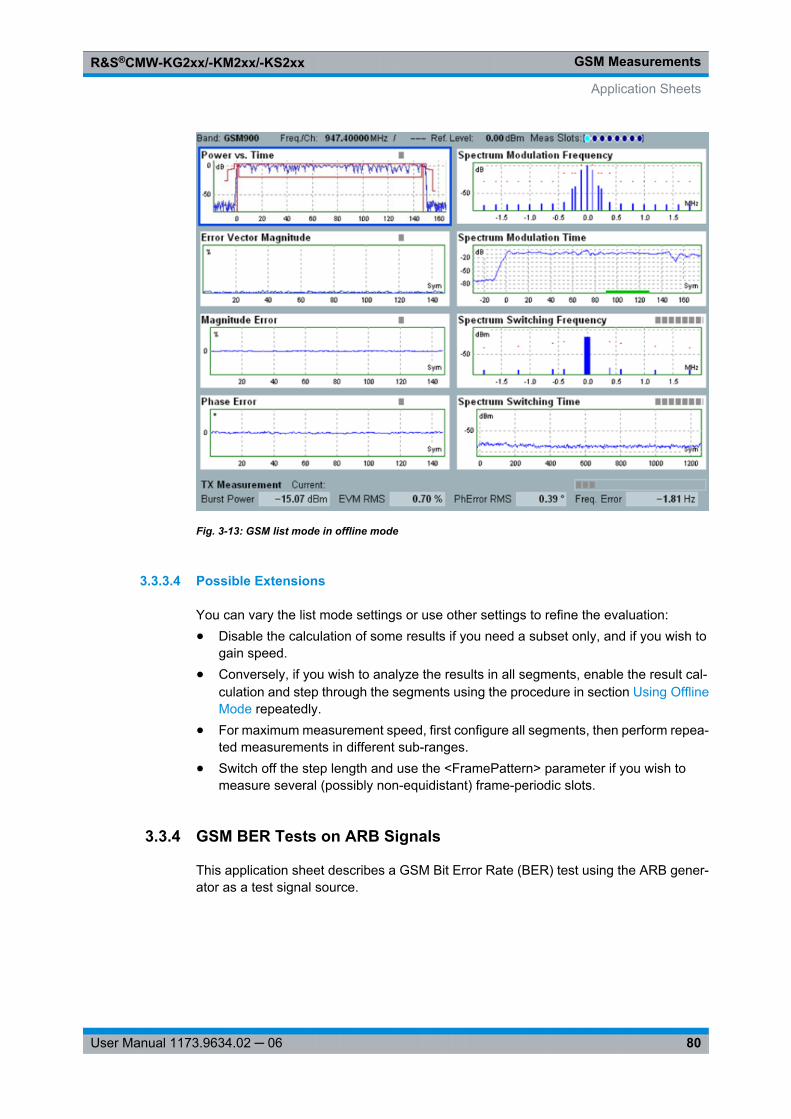
GSM MeasurementsR&S®CMW-KG2xx/-KM2xx/-KS2xx
80User Manual 1173.9634.02 ─ 06
Fig. 3-13: GSM list mode in offline mode
3.3.3.4 Possible Extensions
You can vary the list mode settings or use other settings to refine the evaluation:● Disable the calculation of some results if you need a subset only, and if you wish to
gain speed.● Conversely, if you wish to analyze the results in all segments, enable the result cal-
culation and step through the segments using the procedure in section Using OfflineMode repeatedly.
● For maximum measurement speed, first configure all segments, then perform repea-ted measurements in different sub-ranges.
● Switch off the step length and use the <FramePattern> parameter if you wish tomeasure several (possibly non-equidistant) frame-periodic slots.
3.3.4 GSM BER Tests on ARB Signals
This application sheet describes a GSM Bit Error Rate (BER) test using the ARB gener-ator as a test signal source.
Application Sheets
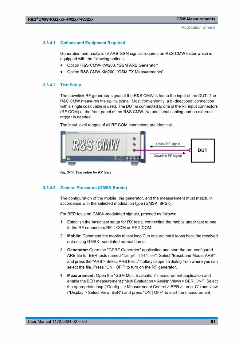
GSM MeasurementsR&S®CMW-KG2xx/-KM2xx/-KS2xx
81User Manual 1173.9634.02 ─ 06
3.3.4.1 Options and Equipment Required
Generation and analysis of ARB GSM signals requires an R&S CMW tester which isequipped with the following options:● Option R&S CMW-KW200, "GSM ARB Generator"● Option R&S CMW-KM200, "GSM TX Measurements"
3.3.4.2 Test Setup
The downlink RF generator signal of the R&S CMW is fed to the input of the DUT. TheR&S CMW measures the uplink signal. Most conveniently, a bi-directional connectionwith a single coax cable is used. The DUT is connected to one of the RF input connectors(RF COM) at the front panel of the R&S CMW. No additional cabling and no externaltrigger is needed.
The input level ranges of all RF COM connectors are identical.
Fig. 3-14: Test setup for RX tests
3.3.4.3 General Procedure (GMSK Bursts)
The configuration of the mobile, the generator, and the measurement must match, inaccordance with the selected modulation type (GMSK, 8PSK).
For BER tests on GMSK-modulated signals, proceed as follows:
1. Establish the basic test setup for RX tests, connecting the mobile under test to oneto the RF connectors RF 1 COM or RF 2 COM.
2. Mobile: Command the mobile to test loop C to ensure that it loops back the receiveddata using GMSK-modulated normal bursts.
3. Generator: Open the "GPRF Generator" application and start the pre-configuredARB file for BER tests named "LoopC_1040.wv": Select "Baseband Mode: ARB"and press the "ARB > Select ARB File..." hotkey to open a dialog from where you canselect the file. Press "ON | OFF" to turn on the RF generator.
4. Measurement: Open the "GSM Multi Evaluation" measurement application andenable the BER measurement ("Multi Evaluation > Assign Views > BER: ON"). Selectthe appropriate loop ("Config... > Measurement Control > BER > Loop: C") and view("Display > Select View: BER") and press "ON | OFF" to start the measurement.
Application Sheets
GSM MeasurementsR&S®CMW-KG2xx/-KM2xx/-KS2xx
82User Manual 1173.9634.02 ─ 06
3.3.4.4 Comparison of GMSK and 8PSK Test Settings
The following table describes the configuration for BER tests on GMSK and 8PSK-modu-lated signals.
Modulation Mobile configuration Generator configuration Measurement configuration
GMSK Test loop C LoopC_1040.wv Loop: C
8PSK SRB loop SRB_8PSK_1040.wv Loop: SRB
The ARB generator signal may be replaced by a real-time generator signal; refer to theseparate application sheet "GSM BER Tests on Real-Time Signals".
3.3.4.5 Additional Information
The properties of the ARB files are reported in section GSM RX Tests.
3.4 GUI Reference
The following sections provide detailed reference information on the Graphical UserInterface (GUI) and the parameters of the GSM multi evaluation measurement.
● Measurement Control..............................................................................................82● Parameters and Settings.........................................................................................83● Measurement Results...........................................................................................107
3.4.1 Measurement Control
The measurement is turned on or off using the ON | OFF or RESTART | STOP keys.
See also: "Measurement Control" in the R&S CMW user manual, chapter "System Over-view"
Multi Evaluation (Softkey)The softkey shows the current measurement state. Additional measurement substatesmay be retrieved via remote control.
Remote command: INITiate: GSM: MEAS<i>: MEValuation STOP: GSM: MEAS<i>: MEValuation ABORt: GSM: MEAS<i>: MEValuation FETCh: GSM: MEAS<i>: MEValuation: STATe? FETCh: GSM: MEAS<i>: MEValuation: STATe: ALL?
GUI Reference
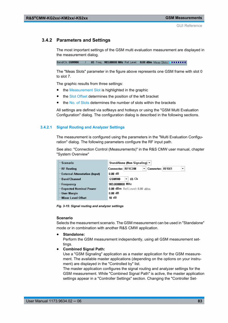
GSM MeasurementsR&S®CMW-KG2xx/-KM2xx/-KS2xx
83User Manual 1173.9634.02 ─ 06
3.4.2 Parameters and Settings
The most important settings of the GSM multi evaluation measurement are displayed inthe measurement dialog.
The "Meas Slots" parameter in the figure above represents one GSM frame with slot 0to slot 7.
The graphic results from three settings:● the Measurement Slot is highlighted in the graphic● the Slot Offset determines the position of the left bracket● the No. of Slots determines the number of slots within the brackets
All settings are defined via softkeys and hotkeys or using the "GSM Multi EvaluationConfiguration" dialog. The configuration dialog is described in the following sections.
3.4.2.1 Signal Routing and Analyzer Settings
The measurement is configured using the parameters in the "Multi Evaluation Configu-ration" dialog. The following parameters configure the RF input path.
See also: "Connection Control (Measurements)" in the R&S CMW user manual, chapter"System Overview"
Fig. 3-15: Signal routing and analyzer settings
ScenarioSelects the measurement scenario. The GSM measurement can be used in "Standalone"mode or in combination with another R&S CMW application.
● Standalone:Perform the GSM measurement independently, using all GSM measurement set-tings.
● Combined Signal Path:Use a "GSM Signaling" application as a master application for the GSM measure-ment. The available master applications (depending on the options on your instru-ment) are displayed in the "Controlled by" list.The master application configures the signal routing and analyzer settings for theGSM measurement. While "Combined Signal Path" is active, the master applicationsettings appear in a "Controller Settings" section. Changing the "Controller Set-
GUI Reference
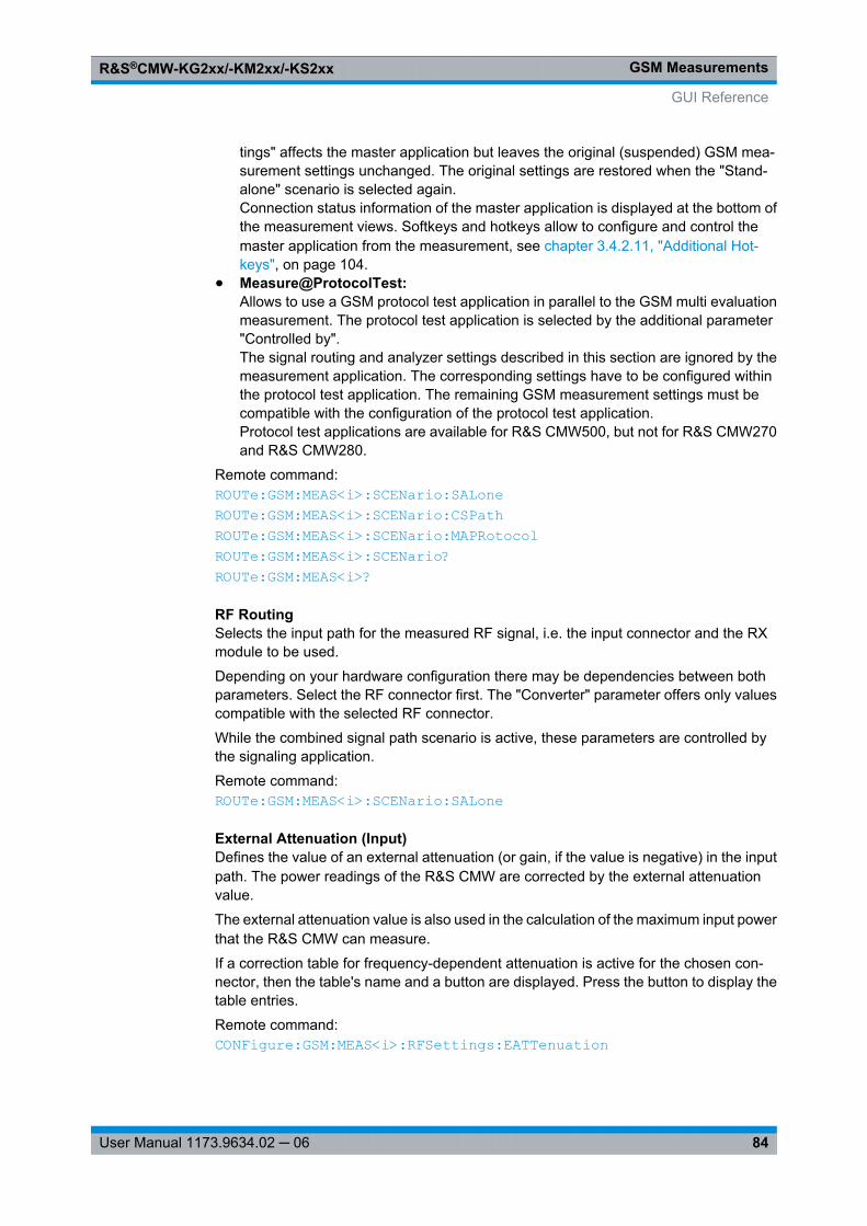
GSM MeasurementsR&S®CMW-KG2xx/-KM2xx/-KS2xx
84User Manual 1173.9634.02 ─ 06
tings" affects the master application but leaves the original (suspended) GSM mea-surement settings unchanged. The original settings are restored when the "Stand-alone" scenario is selected again.Connection status information of the master application is displayed at the bottom ofthe measurement views. Softkeys and hotkeys allow to configure and control themaster application from the measurement, see chapter 3.4.2.11, "Additional Hot-keys", on page 104.
● Measure@ProtocolTest:Allows to use a GSM protocol test application in parallel to the GSM multi evaluationmeasurement. The protocol test application is selected by the additional parameter"Controlled by".The signal routing and analyzer settings described in this section are ignored by themeasurement application. The corresponding settings have to be configured withinthe protocol test application. The remaining GSM measurement settings must becompatible with the configuration of the protocol test application.Protocol test applications are available for R&S CMW500, but not for R&S CMW270and R&S CMW280.
Remote command: ROUTe: GSM: MEAS<i>: SCENario: SALone ROUTe: GSM: MEAS<i>: SCENario: CSPath ROUTe: GSM: MEAS<i>: SCENario: MAPRotocol ROUTe: GSM: MEAS<i>: SCENario? ROUTe: GSM: MEAS<i>?
RF RoutingSelects the input path for the measured RF signal, i.e. the input connector and the RXmodule to be used.
Depending on your hardware configuration there may be dependencies between bothparameters. Select the RF connector first. The "Converter" parameter offers only valuescompatible with the selected RF connector.
While the combined signal path scenario is active, these parameters are controlled bythe signaling application.
Remote command: ROUTe: GSM: MEAS<i>: SCENario: SALone
External Attenuation (Input)Defines the value of an external attenuation (or gain, if the value is negative) in the inputpath. The power readings of the R&S CMW are corrected by the external attenuationvalue.
The external attenuation value is also used in the calculation of the maximum input powerthat the R&S CMW can measure.
If a correction table for frequency-dependent attenuation is active for the chosen con-nector, then the table's name and a button are displayed. Press the button to display thetable entries.
Remote command: CONFigure: GSM: MEAS<i>: RFSettings: EATTenuation
GUI Reference
GSM MeasurementsR&S®CMW-KG2xx/-KM2xx/-KS2xx
85User Manual 1173.9634.02 ─ 06
Band – Channel / FrequencyCenter frequency of the RF analyzer. Set this frequency to the frequency of the measuredRF signal to obtain a meaningful measurement result.
The relation between GSM band, RF frequency and channel number is defined by 3GPP(see GSM Frequency Bands and Channels).
You can specify the RF frequency in two ways:● Enter the frequency directly. The band and channel settings can be ignored or used
for validation of the entered frequency. For validation select the designated band.The channel number resulting from the selected band and frequency is displayed.For an invalid combination no channel number is displayed.
● Select a band and enter a channel number valid for this band. The R&S CMW cal-culates the resulting frequency.
In a combined signal path scenario, the measurement is restricted to valid GSM channels.
Remote command: CONFigure: GSM: MEAS<i>: RFSettings: FREQuency CONFigure: GSM: MEAS<i>: BAND CONFigure: GSM: MEAS<i>: CHANnel
Expected Nominal PowerSets the analyzer in accordance with the nominal power of the RF signal to be measured.The nominal power is the average output power at the DUT during the measurementintervals where the RF transmitter is on. The "Ref. Level" is calculated as the expectedpeak power at the output of the DUT:
Reference level = Expected Nominal Power + User Margin
Note: The actual input power at the connectors (i.e. the "Reference Level" minus the"External Attenuation (Input)" value, if all power settings are configured correctly) mustbe within the level range of the selected RF input connector; refer to the data sheet.
Remote command: CONFigure: GSM: MEAS<i>: RFSettings: ENPower
User MarginMargin that the R&S CMW adds to the "Expected Nominal Power" in order to determineits reference power ("Ref. Level"). The "User Margin" is typically used to account for theknown variations of the RF input signal power, e.g. the variations due to a specific channelconfiguration.
The appropriate values depend on the configuration of the UL GSM signal, e.g. on themodulation scheme. It is small for GMSK-modulated bursts because GMSK is a constant-envelope modulation scheme. For 8PSK (16-QAM)-modulated bursts, a user margin ofapprox. 5 dB (7.5 dB) is sufficient.
Remote command: CONFigure: GSM: MEAS<i>: RFSettings: UMARgin
Mixer Level OffsetVaries the input level of the mixer in the analyzer path. A negative offset reduces themixer input level, a positive offset increases it. Optimize the mixer input level accordingto the properties of the measured signal.
GUI Reference
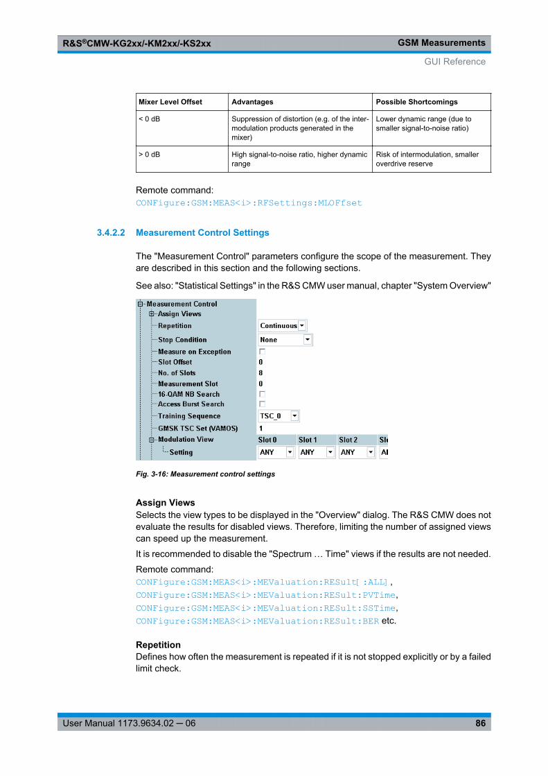
GSM MeasurementsR&S®CMW-KG2xx/-KM2xx/-KS2xx
86User Manual 1173.9634.02 ─ 06
Mixer Level Offset Advantages Possible Shortcomings
< 0 dB Suppression of distortion (e.g. of the inter-modulation products generated in themixer)
Lower dynamic range (due tosmaller signal-to-noise ratio)
> 0 dB High signal-to-noise ratio, higher dynamicrange
Risk of intermodulation, smalleroverdrive reserve
Remote command: CONFigure: GSM: MEAS<i>: RFSettings: MLOFfset
3.4.2.2 Measurement Control Settings
The "Measurement Control" parameters configure the scope of the measurement. Theyare described in this section and the following sections.
See also: "Statistical Settings" in the R&S CMW user manual, chapter "System Overview"
Fig. 3-16: Measurement control settings
Assign ViewsSelects the view types to be displayed in the "Overview" dialog. The R&S CMW does notevaluate the results for disabled views. Therefore, limiting the number of assigned viewscan speed up the measurement.
It is recommended to disable the "Spectrum … Time" views if the results are not needed.
Remote command: CONFigure: GSM: MEAS<i>: MEValuation: RESult[: ALL] ,CONFigure: GSM: MEAS<i>: MEValuation: RESult: PVTime ,CONFigure: GSM: MEAS<i>: MEValuation: RESult: SSTime ,CONFigure: GSM: MEAS<i>: MEValuation: RESult: BER etc.
RepetitionDefines how often the measurement is repeated if it is not stopped explicitly or by a failedlimit check.
GUI Reference
GSM MeasurementsR&S®CMW-KG2xx/-KM2xx/-KS2xx
87User Manual 1173.9634.02 ─ 06
● Continuous: The measurement is continued until it is explicitly terminated; theresults are periodically updated.
● Single-Shot: The measurement is stopped after one statistics cycle.Single-shot is preferable if only a single measurement result is required under fixed con-ditions, which is typical for remote-controlled measurements. Continuous mode is suita-ble for monitoring the evolution of the measurement results in time and observe how theydepend on the measurement configuration, which is typically done in manual control. Thereset/preset values therefore differ from each other.
Remote command: CONFigure: GSM: MEAS<i>: MEValuation: REPetition
Stop ConditionSpecifies the conditions for an early termination of the measurement:● None: The measurement is performed according to its "Repetition" mode and "Sta-
tistic Count", irrespective of the limit check results.● On Limit Failure: The measurement is stopped as soon as one of the limits is
exceeded, irrespective of the repetition mode set. If no limit failure occurs, it is per-formed according to its "Repetition" mode and "Statistic Count". Use this setting formeasurements that are essentially intended for checking limits, e.g. production tests.
Remote command: CONFigure: GSM: MEAS<i>: MEValuation: SCONdition
Measure on ExceptionSpecifies whether measurement results that the R&S CMW identifies as faulty or inac-curate are rejected. A faulty result occurs e.g. when an overload is detected. In remotecontrol, the cause of the error is indicated by the "reliability indicator".
● Off: Faulty results are rejected. The measurement is continued; the statistical coun-ters are not re-set. Use this mode to ensure that a single faulty result does not affectthe entire measurement.
● On: Results are never rejected. Use this mode e.g. for development purposes, if youwant to analyze the reason for occasional wrong transmissions.
Remote command: CONFigure: GSM: MEAS<i>: MEValuation: MOEXception
Slot OffsetSpecifies the start of the measurement interval (measured multislot range) relative to theGSM frame boundary, detected with an internal trigger ("Power" or "Acquisition"); see Defining the Scope of the Measurement.
Remote command: CONFigure: GSM: MEAS<i>: MEValuation: MSLots
No. of SlotsSpecifies the number of slots to be measured and displayed in the different power andmodulation views; see Defining the Scope of the Measurement. The R&S CMW canmeasure between 1 and 8 consecutive slots (1 GSM frame).
Remote command: CONFigure: GSM: MEAS<i>: MEValuation: MSLots
GUI Reference
GSM MeasurementsR&S®CMW-KG2xx/-KM2xx/-KS2xx
88User Manual 1173.9634.02 ─ 06
Measurement SlotSelects the slot to be used for the modulation and spectrum due to modulation measure-ment; see Defining the Scope of the Measurement. The measurement slot must be partof the measured multislot range, therefore:
Slot Offset ≤ Measurement Slot ≤ Slot Offset + No. of Slots – 1
The measurement slot should be active in multislot configurations, because it providesthe 0-dB reference in the "Power vs. Time" diagram.
Remote command: CONFigure: GSM: MEAS<i>: MEValuation: MSLots
16-QAM NB SearchEnables or disables the search for 16-QAM-modulated normal bursts (with optionR&S CMW-KM201). With enabled 16-QAM NB burst search, the R&S CMW can measure16-QAM-modulated normal bursts and other burst types in one multislot range.
The detection of 16-QAM busts is based on the π/4 rotation angle of the I/Q symbols (seealso Multi Evaluation > Rotation). With disabled 16-QAM NB search, the demodulationof 16-QAM bursts will fail. If only one slot is active, the R&S CMW will either detect a8PSK-modulated burst with a very large frequency error or encounter a synchronizationproblem.
Remote command: CONFigure: GSM: MEAS<i>: MEValuation: NBQSearch
Access Burst SearchEnables or disables the search for GMSK-modulated access bursts. With enabled accessburst search, the R&S CMW can measure normal and access bursts in one multislotrange.
The detection of access bursts is based on the three training sequences for access burstsspecified in the GSM standard. The "Training Sequence" setting has no impact on theaccess burst search. The transmission of access bursts is part of the connection setupprocedure. Moreover, a mobile in packet data mode can use periodic access bursts forthe transmission of CONTROL_ACK_TYPE messages.
The access burst search is time-consuming because the R&S CMW has to search forone out of three possible training sequences within a relatively wide time interval.
Remote command: CONFigure: GSM: MEAS<i>: MEValuation: ABSearch
Training SequenceSelects the training sequence of the analyzed bursts: With a specific training sequencesetting, the R&S CMW will analyze bursts with this training sequence only. The settinghas no impact on the access burst search.
● TSC 0 to TSC 7: One of the 8 26-bit training sequences defined in the GSM standard● Dummy: GSM-specific dummy burst● TSC Any: Search for any of the training sequences TSC 0 to TSC 7; use the detected
training sequence for synchronization.
GUI Reference
GSM MeasurementsR&S®CMW-KG2xx/-KM2xx/-KS2xx
89User Manual 1173.9634.02 ─ 06
● Off: Do not decode the training sequence, measure any burst. This mode is appro-priate for a rough analysis only because the R&S CMW cannot use the trainingsequence for synchronization and for compensation of a time drift.
Remote command: CONFigure: GSM: MEAS<i>: MEValuation: TSEQuence
GSM TSC Set (VAMOS)Specifies the expected VAMOS Training Sequence Code (TSC) set of the measuredGSM uplink signal. With a specific TSC set selection, the R&S CMW will analyze burstswith this TSC set only.
The two TSC sets 1 and 2 identify the uplink subchannel for a VAMOS user. All mobilesmust support TSC set 1, but only mobiles explicitly indicating support for VAMOS mustalso support TSC set 2. VAMOS stands for "Voice services over Adaptive Multi-userchannels on One Slot" and is defined in 3GPP TS 45.001. For a short introduction referto the documentation of the "GSM Signaling" application.
Remote command: CONFigure: GSM: MEAS<i>: MEValuation: VAMos: TSCSet
Modulation ViewDefines the expected modulation scheme and burst type in all measured timeslots andadjusts the Power Templates. The modulation view settings act as a filter for the triggeredGSM frames: To obtain a valid measurement result, the actual modulation scheme andburst type in all measured slots must be compatible with the "Modulation View" settings.Incompatible frames are rejected. For application examples see Detecting GSM MultislotFrames.
● GMSK: GMSK modulation and normal bursts expected; the GMSK template is used.● 8PSK: 8PSK modulation and normal bursts expected; the 8PSK template is used.● 16QAM: 16-QAM modulation and normal bursts expected; the 16QAM template is
used (with option R&S CMW-KM201).● Access: Access bursts expected; the template for access bursts is used. The access
burst search must be active for this setting.● Any: Arbitrary modulation scheme and burst type; the R&S CMW determines the
modulation of the measured burst and uses the appropriate template. Valid resultsare obtained with all supported modulation types.
● Off: No signal expected: timeslot must be inactive to obtain a valid result.Note: If the burst type or modulation scheme changes during the measurement, themodulation view setting "Any" can cause inconsistent statistical results. In general, acomparison or average of the results for different burst types does not make sense.Moreover, the R&S CMW has to adjust the evaluation areas and oversampling factors tothe burst type, which makes the different traces incompatible.The evaluation areas and oversampling factors for the different burst types are automat-ically selected in accordance with the GSM conformance test specification. The followingtable gives an overview.
GUI Reference
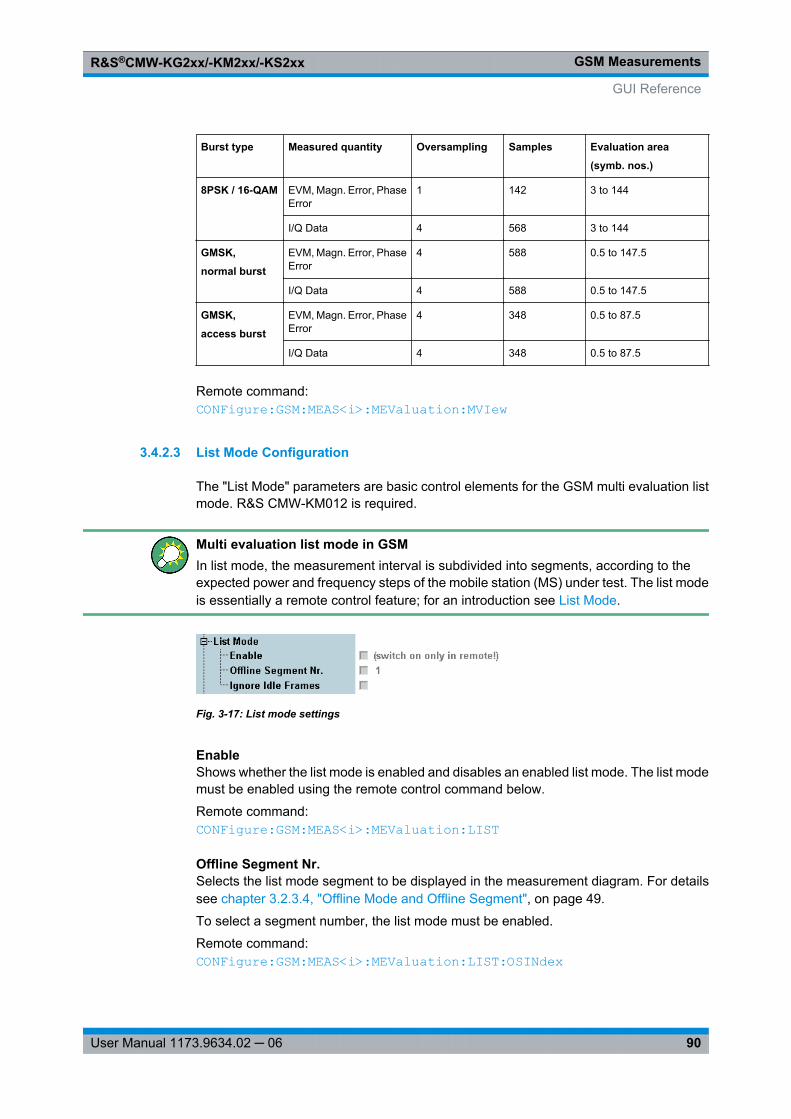
GSM MeasurementsR&S®CMW-KG2xx/-KM2xx/-KS2xx
90User Manual 1173.9634.02 ─ 06
Burst type Measured quantity Oversampling Samples Evaluation area
(symb. nos.)
8PSK / 16-QAM EVM, Magn. Error, PhaseError
1 142 3 to 144
I/Q Data 4 568 3 to 144
GMSK,
normal burst
EVM, Magn. Error, PhaseError
4 588 0.5 to 147.5
I/Q Data 4 588 0.5 to 147.5
GMSK,
access burst
EVM, Magn. Error, PhaseError
4 348 0.5 to 87.5
I/Q Data 4 348 0.5 to 87.5
Remote command: CONFigure: GSM: MEAS<i>: MEValuation: MVIew
3.4.2.3 List Mode Configuration
The "List Mode" parameters are basic control elements for the GSM multi evaluation listmode. R&S CMW-KM012 is required.
Multi evaluation list mode in GSMIn list mode, the measurement interval is subdivided into segments, according to theexpected power and frequency steps of the mobile station (MS) under test. The list modeis essentially a remote control feature; for an introduction see List Mode.
Fig. 3-17: List mode settings
EnableShows whether the list mode is enabled and disables an enabled list mode. The list modemust be enabled using the remote control command below.
Remote command: CONFigure: GSM: MEAS<i>: MEValuation: LIST
Offline Segment Nr.Selects the list mode segment to be displayed in the measurement diagram. For detailssee chapter 3.2.3.4, "Offline Mode and Offline Segment", on page 49.
To select a segment number, the list mode must be enabled.
Remote command: CONFigure: GSM: MEAS<i>: MEValuation: LIST: OSINdex
GUI Reference
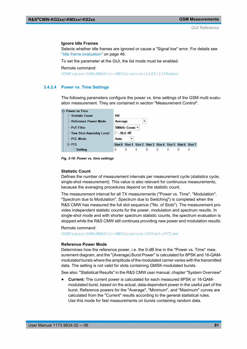
GSM MeasurementsR&S®CMW-KG2xx/-KM2xx/-KS2xx
91User Manual 1173.9634.02 ─ 06
Ignore Idle FramesSelects whether idle frames are ignored or cause a "Signal low" error. For details see "Idle frame evaluation" on page 46.
To set the parameter at the GUI, the list mode must be enabled.
Remote command: CONFigure: GSM: MEAS<i>: MEValuation: LIST: IIFRames
3.4.2.4 Power vs. Time Settings
The following parameters configure the power vs. time settings of the GSM multi evalu-ation measurement. They are contained in section "Measurement Control".
Fig. 3-18: Power vs. time settings
Statistic CountDefines the number of measurement intervals per measurement cycle (statistics cycle,single-shot measurement). This value is also relevant for continuous measurements,because the averaging procedures depend on the statistic count.
The measurement interval for all TX measurements ("Power vs. Time", "Modulation","Spectrum due to Modulation", Spectrum due to Switching") is completed when theR&S CMW has measured the full slot sequence ("No. of Slots"). The measurement pro-vides independent statistic counts for the power, modulation and spectrum results. Insingle-shot mode and with shorter spectrum statistic counts, the spectrum evaluation isstopped while the R&S CMW still continues providing new power and modulation results.
Remote command: CONFigure: GSM: MEAS<i>: MEValuation: SCOunt: PVTime
Reference Power ModeDetermines how the reference power, i.e. the 0-dB line in the "Power vs. Time" mea-surement diagram, and the "(Average) Burst Power" is calculated for 8PSK and 16-QAM-modulated bursts where the amplitude of the modulated carrier varies with the transmitteddata. The setting is not valid for slots containing GMSK-modulated bursts.
See also: "Statistical Results" in the R&S CMW user manual, chapter "System Overview"
● Current: The current power is calculated for each measured 8PSK or 16-QAM-modulated burst, based on the actual, data-dependent power in the useful part of theburst. Reference powers for the "Average", "Minimum", and "Maximum" curves arecalculated from the "Current" results according to the general statistical rules.Use this mode for fast measurements on bursts containing random data.
GUI Reference
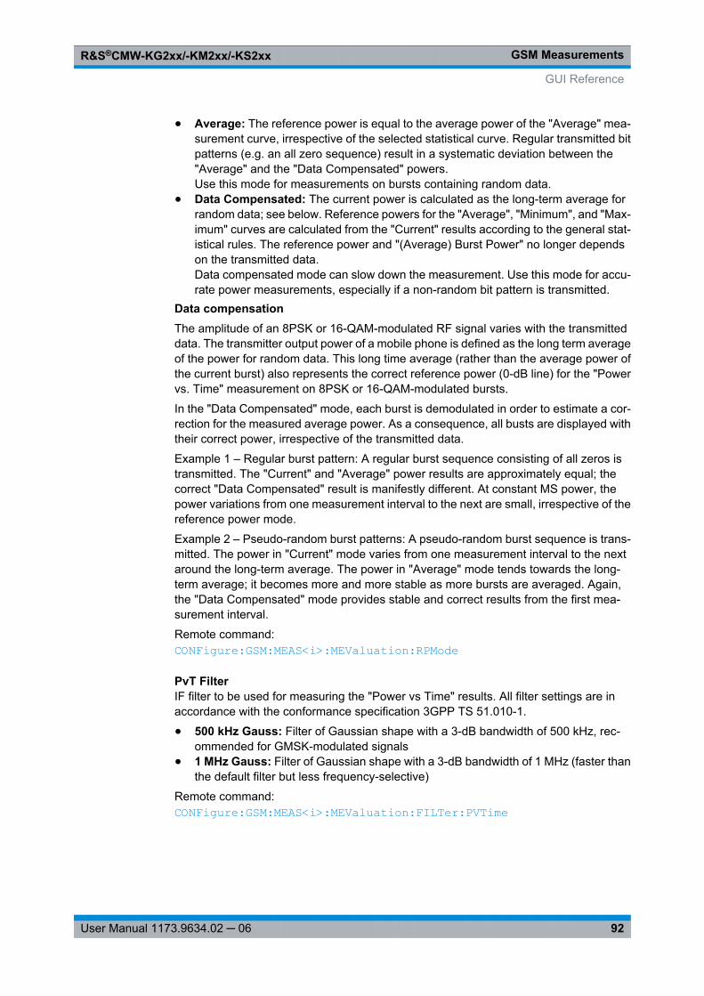
GSM MeasurementsR&S®CMW-KG2xx/-KM2xx/-KS2xx
92User Manual 1173.9634.02 ─ 06
● Average: The reference power is equal to the average power of the "Average" mea-surement curve, irrespective of the selected statistical curve. Regular transmitted bitpatterns (e.g. an all zero sequence) result in a systematic deviation between the"Average" and the "Data Compensated" powers.Use this mode for measurements on bursts containing random data.
● Data Compensated: The current power is calculated as the long-term average forrandom data; see below. Reference powers for the "Average", "Minimum", and "Max-imum" curves are calculated from the "Current" results according to the general stat-istical rules. The reference power and "(Average) Burst Power" no longer dependson the transmitted data.Data compensated mode can slow down the measurement. Use this mode for accu-rate power measurements, especially if a non-random bit pattern is transmitted.
Data compensationThe amplitude of an 8PSK or 16-QAM-modulated RF signal varies with the transmitteddata. The transmitter output power of a mobile phone is defined as the long term averageof the power for random data. This long time average (rather than the average power ofthe current burst) also represents the correct reference power (0-dB line) for the "Powervs. Time" measurement on 8PSK or 16-QAM-modulated bursts.
In the "Data Compensated" mode, each burst is demodulated in order to estimate a cor-rection for the measured average power. As a consequence, all busts are displayed withtheir correct power, irrespective of the transmitted data.
Example 1 – Regular burst pattern: A regular burst sequence consisting of all zeros istransmitted. The "Current" and "Average" power results are approximately equal; thecorrect "Data Compensated" result is manifestly different. At constant MS power, thepower variations from one measurement interval to the next are small, irrespective of thereference power mode.
Example 2 – Pseudo-random burst patterns: A pseudo-random burst sequence is trans-mitted. The power in "Current" mode varies from one measurement interval to the nextaround the long-term average. The power in "Average" mode tends towards the long-term average; it becomes more and more stable as more bursts are averaged. Again,the "Data Compensated" mode provides stable and correct results from the first mea-surement interval.
Remote command: CONFigure: GSM: MEAS<i>: MEValuation: RPMode
PvT FilterIF filter to be used for measuring the "Power vs Time" results. All filter settings are inaccordance with the conformance specification 3GPP TS 51.010-1.
● 500 kHz Gauss: Filter of Gaussian shape with a 3-dB bandwidth of 500 kHz, rec-ommended for GMSK-modulated signals
● 1 MHz Gauss: Filter of Gaussian shape with a 3-dB bandwidth of 1 MHz (faster thanthe default filter but less frequency-selective)
Remote command: CONFigure: GSM: MEAS<i>: MEValuation: FILTer: PVTime
GUI Reference
GSM MeasurementsR&S®CMW-KG2xx/-KM2xx/-KS2xx
93User Manual 1173.9634.02 ─ 06
Two Shot Assembly LevelEnables or disables the two-shot measurement mode for high dynamic range and definesan assembly level for the two consecutive measurement results.
In the two-shot measurement the multislot range is measured in two frames using twodifferent "Expected Nominal Power" settings. The results of the two stages are combinedand displayed together in the "Power vs. Time" diagram.
The two maximum levels differ by 30 dB, which means that – depending on the levelrange of the MS under test and the external test setup – a gain in dynamic range up to30 dB can be achieved. The two stage measurement ensures a sufficient dynamic rangefor arbitrary slot powers but increases the measurement time by a factor of 2.
The assembly level is the signal level relative to the reference level (the "Expected Nom-inal Power" plus the "User Margin") where the two results obtained in a two stage mea-surement are joined together: All trace points above the assembly level are obtained witha large "Expected Nominal Power", the ones below are measured with lower "ExpectedNominal Power".
The assembly level is ignored as long as the two-shot mode is disabled.
Remote command: CONFigure: GSM: MEAS<i>: MEValuation: HDALevel
PCL ModeDefines how the R&S CMW determines the PCL of the measured signal.● Auto: The R&S CMW estimates the PCL in each timeslot according to the measured
average burst power. The dynamic limit lines are calculated according to the estima-ted PCL values. The "PCL > Setting" values are ignored; no PCL setting is required.
● PCL: The R&S CMW expects an input signal in accordance with the "PCL > Set-ting" values. The specified values are also used for the dynamic limit lines. Incorrectsettings can cause wrong limit check results.
Remote command: CONFigure: GSM: MEAS<i>: MEValuation: PCLMode
PCL > SettingSets the expected PCL values in all timeslots, to be used in "PCL Mode: PCL". See "PCLMode" on page 93. The list mode provides segment-specific PCL settings.
Note: The PCL values are interpreted according to the current GSM band setting; see table 3-4.
Remote command: CONFigure: GSM: MEAS<i>: MEValuation: PCL
3.4.2.5 Modulation Settings
The following parameters configure the modulation settings of the GSM multi evaluationmeasurement. They are contained in section "Measurement Control".
GUI Reference
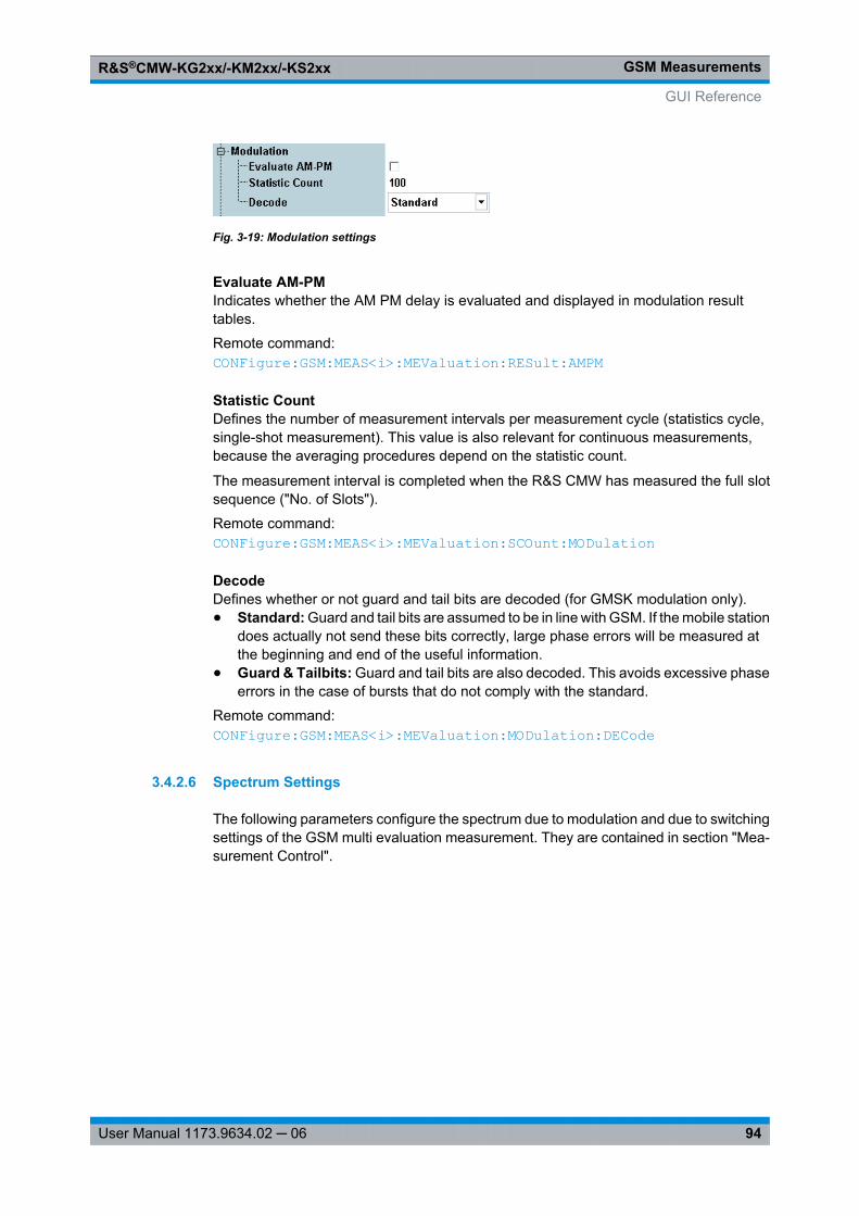
GSM MeasurementsR&S®CMW-KG2xx/-KM2xx/-KS2xx
94User Manual 1173.9634.02 ─ 06
Fig. 3-19: Modulation settings
Evaluate AM-PMIndicates whether the AM PM delay is evaluated and displayed in modulation resulttables.
Remote command: CONFigure: GSM: MEAS<i>: MEValuation: RESult: AMPM
Statistic CountDefines the number of measurement intervals per measurement cycle (statistics cycle,single-shot measurement). This value is also relevant for continuous measurements,because the averaging procedures depend on the statistic count.
The measurement interval is completed when the R&S CMW has measured the full slotsequence ("No. of Slots").
Remote command: CONFigure: GSM: MEAS<i>: MEValuation: SCOunt: MODulation
DecodeDefines whether or not guard and tail bits are decoded (for GMSK modulation only).● Standard: Guard and tail bits are assumed to be in line with GSM. If the mobile station
does actually not send these bits correctly, large phase errors will be measured atthe beginning and end of the useful information.
● Guard & Tailbits: Guard and tail bits are also decoded. This avoids excessive phaseerrors in the case of bursts that do not comply with the standard.
Remote command: CONFigure: GSM: MEAS<i>: MEValuation: MODulation: DECode
3.4.2.6 Spectrum Settings
The following parameters configure the spectrum due to modulation and due to switchingsettings of the GSM multi evaluation measurement. They are contained in section "Mea-surement Control".
GUI Reference
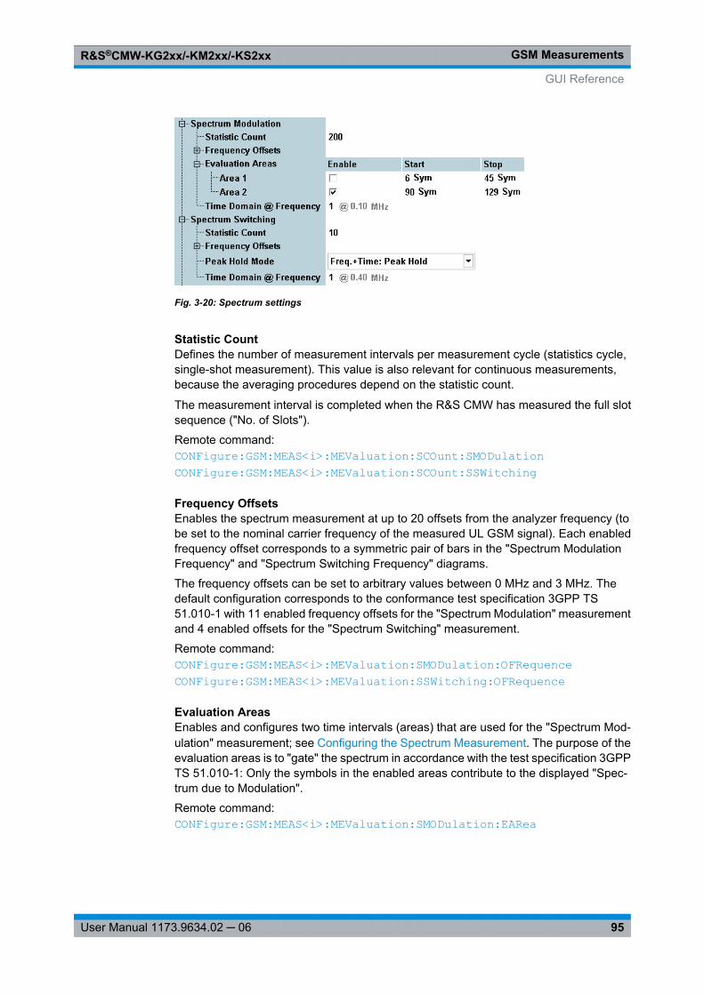
GSM MeasurementsR&S®CMW-KG2xx/-KM2xx/-KS2xx
95User Manual 1173.9634.02 ─ 06
Fig. 3-20: Spectrum settings
Statistic CountDefines the number of measurement intervals per measurement cycle (statistics cycle,single-shot measurement). This value is also relevant for continuous measurements,because the averaging procedures depend on the statistic count.
The measurement interval is completed when the R&S CMW has measured the full slotsequence ("No. of Slots").
Remote command: CONFigure: GSM: MEAS<i>: MEValuation: SCOunt: SMODulation CONFigure: GSM: MEAS<i>: MEValuation: SCOunt: SSWitching
Frequency OffsetsEnables the spectrum measurement at up to 20 offsets from the analyzer frequency (tobe set to the nominal carrier frequency of the measured UL GSM signal). Each enabledfrequency offset corresponds to a symmetric pair of bars in the "Spectrum ModulationFrequency" and "Spectrum Switching Frequency" diagrams.
The frequency offsets can be set to arbitrary values between 0 MHz and 3 MHz. Thedefault configuration corresponds to the conformance test specification 3GPP TS51.010-1 with 11 enabled frequency offsets for the "Spectrum Modulation" measurementand 4 enabled offsets for the "Spectrum Switching" measurement.
Remote command: CONFigure: GSM: MEAS<i>: MEValuation: SMODulation: OFRequence CONFigure: GSM: MEAS<i>: MEValuation: SSWitching: OFRequence
Evaluation AreasEnables and configures two time intervals (areas) that are used for the "Spectrum Mod-ulation" measurement; see Configuring the Spectrum Measurement. The purpose of theevaluation areas is to "gate" the spectrum in accordance with the test specification 3GPPTS 51.010-1: Only the symbols in the enabled areas contribute to the displayed "Spec-trum due to Modulation".
Remote command: CONFigure: GSM: MEAS<i>: MEValuation: SMODulation: EARea
GUI Reference
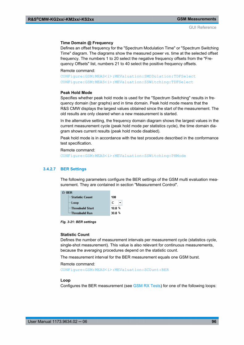
GSM MeasurementsR&S®CMW-KG2xx/-KM2xx/-KS2xx
96User Manual 1173.9634.02 ─ 06
Time Domain @ FrequencyDefines an offset frequency for the "Spectrum Modulation Time" or "Spectrum SwitchingTime" diagram. The diagrams show the measured power vs. time at the selected offsetfrequency. The numbers 1 to 20 select the negative frequency offsets from the "Fre-quency Offsets" list, numbers 21 to 40 select the positive frequency offsets.
Remote command: CONFigure: GSM: MEAS<i>: MEValuation: SMODulation: TDFSelect CONFigure: GSM: MEAS<i>: MEValuation: SSWitching: TDFSelect
Peak Hold ModeSpecifies whether peak hold mode is used for the "Spectrum Switching" results in fre-quency domain (bar graphs) and in time domain. Peak hold mode means that theR&S CMW displays the largest values obtained since the start of the measurement. Theold results are only cleared when a new measurement is started.
In the alternative setting, the frequency domain diagram shows the largest values in thecurrent measurement cycle (peak hold mode per statistics cycle), the time domain dia-gram shows current results (peak hold mode disabled).
Peak hold mode is in accordance with the test procedure described in the conformancetest specification.
Remote command: CONFigure: GSM: MEAS<i>: MEValuation: SSWitching: PHMode
3.4.2.7 BER Settings
The following parameters configure the BER settings of the GSM multi evaluation mea-surement. They are contained in section "Measurement Control".
Fig. 3-21: BER settings
Statistic CountDefines the number of measurement intervals per measurement cycle (statistics cycle,single-shot measurement). This value is also relevant for continuous measurements,because the averaging procedures depend on the statistic count.
The measurement interval for the BER measurement equals one GSM burst.
Remote command: CONFigure: GSM: MEAS<i>: MEValuation: SCOunt: BER
LoopConfigures the BER measurement (see GSM RX Tests) for one of the following loops:
GUI Reference
GSM MeasurementsR&S®CMW-KG2xx/-KM2xx/-KS2xx
97User Manual 1173.9634.02 ─ 06
"C" The R&S CMW assumes that a BER test on GMSK-modulated signalsis performed, i.e. that loop C is closed at the mobile under test, and oneof the following data sources is used:● The ARB generator uses the LoopC_1040.wv file.
● The GSM real-time generator provides an "Alternating" bit pattern.
"SRB" The R&S CMW assumes that a BER test on 8PSK-modulated signalsis performed, i.e. that an SRB loop is closed at the mobile under test,and one of the following data sources is used:● The ARB generator uses the SRB_8PSK_1040.wv file.
● The GSM real-time generator provides a "BER Test" bit pattern.
Remote command: CONFigure: GSM: MEAS<i>: MEValuation: BER: LOOP
Threshold StartDefines a maximum bit error rate for the first evaluated burst. The purpose of this param-eter is to avoid misleading BER results due to non-TCH bursts (e.g. SACCH bursts). TheBER measurement will start with the first triggered burst providing a BER below the"Threshold Start" value, which is likely to be a TCH burst.
To improve the accuracy of the BER measurement, you can set the "Threshold Start" toa value that is close to the expected BER.
Remote command: CONFigure: GSM: MEAS<i>: MEValuation: BER: TSTart
Threshold RunDefines a maximum bit error rate for the evaluated bursts following the first burst. Thepurpose of this parameter is to avoid misleading BER results due to non-TCH bursts (e.g.SACCH bursts). The BER measurement will be based on bursts with a bit error rate belowthe "Threshold Run" value only, which are likely to be TCH bursts.
For varying test conditions, the threshold should be well above the expected BER. Itshould also be well below the expected BER of non-TCH bursts (50 %). Note that theBER measurement does not display BER results above 30 %; see GSM RX Tests.
Remote command: CONFigure: GSM: MEAS<i>: MEValuation: BER: TRUN
3.4.2.8 Trigger Settings
The "Trigger" parameters configure the trigger system for the GSM multi evaluation mea-surement.
GUI Reference
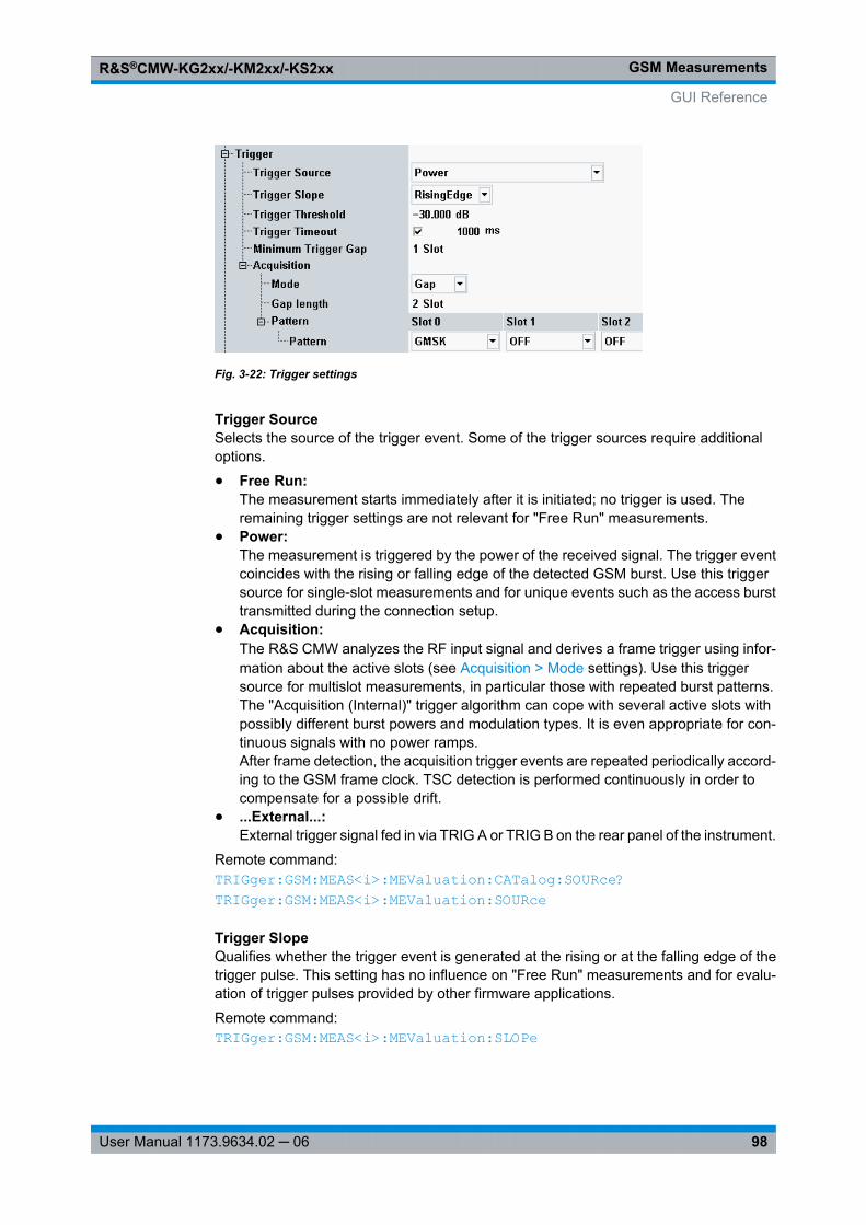
GSM MeasurementsR&S®CMW-KG2xx/-KM2xx/-KS2xx
98User Manual 1173.9634.02 ─ 06
Fig. 3-22: Trigger settings
Trigger SourceSelects the source of the trigger event. Some of the trigger sources require additionaloptions.
● Free Run:The measurement starts immediately after it is initiated; no trigger is used. Theremaining trigger settings are not relevant for "Free Run" measurements.
● Power:The measurement is triggered by the power of the received signal. The trigger eventcoincides with the rising or falling edge of the detected GSM burst. Use this triggersource for single-slot measurements and for unique events such as the access bursttransmitted during the connection setup.
● Acquisition:The R&S CMW analyzes the RF input signal and derives a frame trigger using infor-mation about the active slots (see Acquisition > Mode settings). Use this triggersource for multislot measurements, in particular those with repeated burst patterns.The "Acquisition (Internal)" trigger algorithm can cope with several active slots withpossibly different burst powers and modulation types. It is even appropriate for con-tinuous signals with no power ramps.After frame detection, the acquisition trigger events are repeated periodically accord-ing to the GSM frame clock. TSC detection is performed continuously in order tocompensate for a possible drift.
● ...External...:External trigger signal fed in via TRIG A or TRIG B on the rear panel of the instrument.
Remote command: TRIGger: GSM: MEAS<i>: MEValuation: CATalog: SOURce? TRIGger: GSM: MEAS<i>: MEValuation: SOURce
Trigger SlopeQualifies whether the trigger event is generated at the rising or at the falling edge of thetrigger pulse. This setting has no influence on "Free Run" measurements and for evalu-ation of trigger pulses provided by other firmware applications.
Remote command: TRIGger: GSM: MEAS<i>: MEValuation: SLOPe
GUI Reference
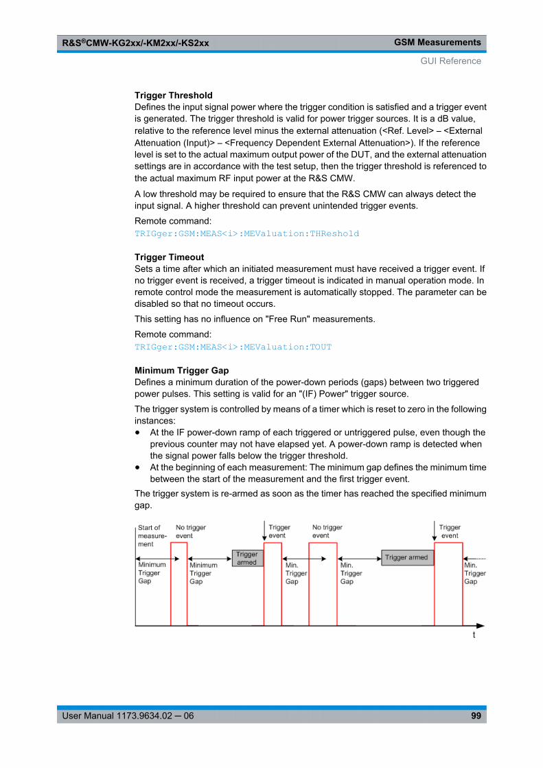
GSM MeasurementsR&S®CMW-KG2xx/-KM2xx/-KS2xx
99User Manual 1173.9634.02 ─ 06
Trigger ThresholdDefines the input signal power where the trigger condition is satisfied and a trigger eventis generated. The trigger threshold is valid for power trigger sources. It is a dB value,relative to the reference level minus the external attenuation (<Ref. Level> – <ExternalAttenuation (Input)> – <Frequency Dependent External Attenuation>). If the referencelevel is set to the actual maximum output power of the DUT, and the external attenuationsettings are in accordance with the test setup, then the trigger threshold is referenced tothe actual maximum RF input power at the R&S CMW.
A low threshold may be required to ensure that the R&S CMW can always detect theinput signal. A higher threshold can prevent unintended trigger events.
Remote command: TRIGger: GSM: MEAS<i>: MEValuation: THReshold
Trigger TimeoutSets a time after which an initiated measurement must have received a trigger event. Ifno trigger event is received, a trigger timeout is indicated in manual operation mode. Inremote control mode the measurement is automatically stopped. The parameter can bedisabled so that no timeout occurs.
This setting has no influence on "Free Run" measurements.
Remote command: TRIGger: GSM: MEAS<i>: MEValuation: TOUT
Minimum Trigger GapDefines a minimum duration of the power-down periods (gaps) between two triggeredpower pulses. This setting is valid for an "(IF) Power" trigger source.
The trigger system is controlled by means of a timer which is reset to zero in the followinginstances:● At the IF power-down ramp of each triggered or untriggered pulse, even though the
previous counter may not have elapsed yet. A power-down ramp is detected whenthe signal power falls below the trigger threshold.
● At the beginning of each measurement: The minimum gap defines the minimum timebetween the start of the measurement and the first trigger event.
The trigger system is re-armed as soon as the timer has reached the specified minimumgap.
GUI Reference
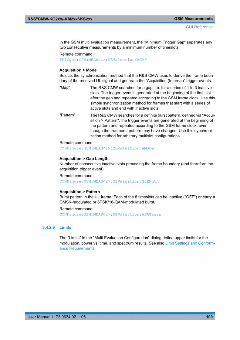
GSM MeasurementsR&S®CMW-KG2xx/-KM2xx/-KS2xx
100User Manual 1173.9634.02 ─ 06
In the GSM multi evaluation measurement, the "Minimum Trigger Gap" separates anytwo consecutive measurements by a minimum number of timeslots.
Remote command: TRIGger: GSM: MEAS<i>: MEValuation: MGAP
Acquisition > ModeSelects the synchronization method that the R&S CMW uses to derive the frame boun-dary of the received UL signal and generate the "Acquisition (Internal)" trigger events.
"Gap" The R&S CMW searches for a gap, i.e. for a series of 1 to 3 inactiveslots. The trigger event is generated at the beginning of the first slotafter the gap and repeated according to the GSM frame clock. Use thissimple synchronization method for frames that start with a series ofactive slots and end with inactive slots.
"Pattern" The R&S CMW searches for a definite burst pattern, defined via "Acqui-sition > Pattern".The trigger events are generated at the beginning ofthe pattern and repeated according to the GSM frame clock, eventhough the true burst pattern may have changed. Use this synchroni-zation method for arbitrary multislot configurations.
Remote command: CONFigure: GSM: MEAS<i>: MEValuation: AMODe
Acquisition > Gap LengthNumber of consecutive inactive slots preceding the frame boundary (and therefore theacquisition trigger event).
Remote command: CONFigure: GSM: MEAS<i>: MEValuation: GLENgth
Acquisition > PatternBurst pattern in the UL frame. Each of the 8 timeslots can be inactive ("OFF") or carry aGMSK-modulated or 8PSK/16-QAM-modulated burst.
Remote command: CONFigure: GSM: MEAS<i>: MEValuation: APATtern
3.4.2.9 Limits
The "Limits" in the "Multi Evaluation Configuration" dialog define upper limits for themodulation, power vs. time, and spectrum results. See also Limit Settings and Conform-ance Requirements.
GUI Reference
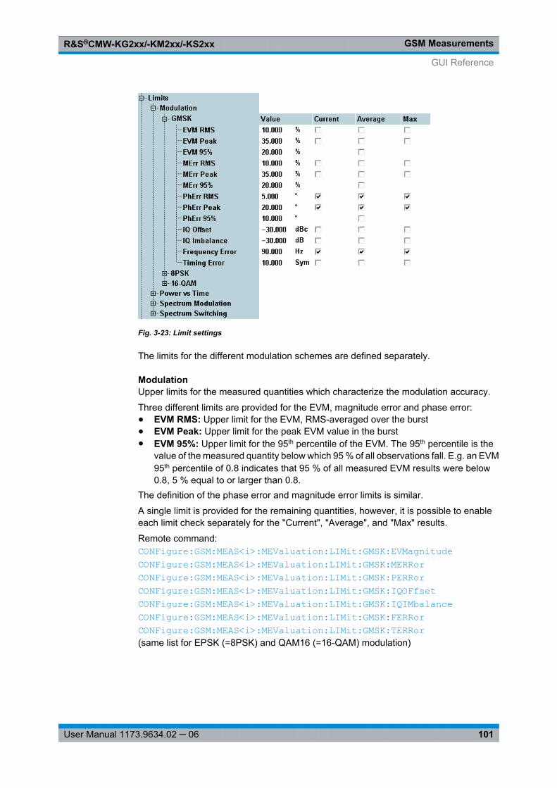
GSM MeasurementsR&S®CMW-KG2xx/-KM2xx/-KS2xx
101User Manual 1173.9634.02 ─ 06
Fig. 3-23: Limit settings
The limits for the different modulation schemes are defined separately.
ModulationUpper limits for the measured quantities which characterize the modulation accuracy.
Three different limits are provided for the EVM, magnitude error and phase error:● EVM RMS: Upper limit for the EVM, RMS-averaged over the burst● EVM Peak: Upper limit for the peak EVM value in the burst● EVM 95%: Upper limit for the 95th percentile of the EVM. The 95th percentile is the
value of the measured quantity below which 95 % of all observations fall. E.g. an EVM95th percentile of 0.8 indicates that 95 % of all measured EVM results were below0.8, 5 % equal to or larger than 0.8.
The definition of the phase error and magnitude error limits is similar.
A single limit is provided for the remaining quantities, however, it is possible to enableeach limit check separately for the "Current", "Average", and "Max" results.
Remote command: CONFigure: GSM: MEAS<i>: MEValuation: LIMit: GMSK: EVMagnitude CONFigure: GSM: MEAS<i>: MEValuation: LIMit: GMSK: MERRor CONFigure: GSM: MEAS<i>: MEValuation: LIMit: GMSK: PERRor CONFigure: GSM: MEAS<i>: MEValuation: LIMit: GMSK: IQOFfset CONFigure: GSM: MEAS<i>: MEValuation: LIMit: GMSK: IQIMbalance CONFigure: GSM: MEAS<i>: MEValuation: LIMit: GMSK: FERRor CONFigure: GSM: MEAS<i>: MEValuation: LIMit: GMSK: TERRor (same list for EPSK (=8PSK) and QAM16 (=16-QAM) modulation)
GUI Reference
GSM MeasurementsR&S®CMW-KG2xx/-KM2xx/-KS2xx
102User Manual 1173.9634.02 ─ 06
Power vs. Time > Avg. Burst PowerUpper and lower limits for the burst power, averaged over all symbols in the useful partof the burst. According to the conformance specification (see Avg. Burst Power Limits),the average burst power limits depend on the transmitter output power of the mobilephone, defined in terms of the Power Control Level (PCL). The limits are relative to thenominal output power of the mobile phone, corresponding to its PCL.
The R&S CMW can define and enable limits for 10 independent PCL ranges (from PCL ...to PCL). For greater flexibility, lower and upper limits may be asymmetric (i.e. not of thesame magnitude).
"Guard Period" is relevant for multislot configurations; this value specifies the maximumpower in the guard period between any two consecutive active slots; see Power Tem-plates. The multislot guard level is defined as a dB value relative to the average burstpower in the Measurement Slot.
Remote command: CONFigure: GSM: MEAS<i>: MEValuation: LIMit: PVTime: ABPower<no> CONFigure: GSM: MEAS<i>: MEValuation: LIMit: PVTime: GPLevel
Power vs. Time > Power TemplatesUpper and lower limit lines for the measured power vs. time. The limit lines for the differentmodulation schemes can be set independently; see Power Templates.
Both upper limit lines and lower limit lines consist of several areas. In each of these areas,it is possible to specify a relative limit (in dBc units) and an alternative absolute limit. If itis enabled, the absolute limit replaces the relative limit whenever it is above the relativelimit. These "Static" (i.e. power-independent) limit settings can be further modified byadding a "Dynamic" (i.e. PCL-dependent) correction.
The power templates of the R&S CMW are more flexible than necessary to define thetemplates specified in the conformance test specification.
Note: Dynamic correction. If the "GSM Multi Evaluation" measurement is performed incombination with the "GSM Signaling" application, the PCL value for the dynamic cor-
GUI Reference
GSM MeasurementsR&S®CMW-KG2xx/-KM2xx/-KS2xx
103User Manual 1173.9634.02 ─ 06
rection is taken from the signaling application. In "Standalone (Non Signaling)" mode theR&S CMW estimates the PCL according to the received average burst power.
Remote command: CONFigure: GSM: MEAS<i>: MEValuation: LIMit: GMSK: PVTime: UPPer: REDGe<no>: STATic CONFigure: GSM: MEAS<i>: MEValuation: LIMit: GMSK: PVTime: UPPer: UPARt<no>: STATic CONFigure: GSM: MEAS<i>: MEValuation: LIMit: GMSK: PVTime: UPPer: FEDGe<no>: STATic CONFigure: GSM: MEAS<i>: MEValuation: LIMit: GMSK: PVTime: LOWer: UPARt<no>: STATic CONFigure: GSM: MEAS<i>: MEValuation: LIMit: GMSK: PVTime: UPPer: REDGe<no>: DYNamic<Range> CONFigure: GSM: MEAS<i>: MEValuation: LIMit: GMSK: PVTime: UPPer: UPARt<no>: DYNamic<Range> CONFigure: GSM: MEAS<i>: MEValuation: LIMit: GMSK: PVTime: UPPer: FEDGe<no>: DYNamic<Range> CONFigure: GSM: MEAS<i>: MEValuation: LIMit: GMSK: PVTime: LOWer: UPARt<no>: DYNamic<Range> (same list for EPSK (=8PSK) and QAM16 (=16-QAM) modulation)
Spectrum Modulation and Spectrum SwitchingUpper limits for spectrum due to modulation and spectrum due to switching; see Spec-trum Limits. The limits for the different modulation schemes can be defined independ-ently, each at up to 20 different offsets from the nominal carrier frequency. The offsetfrequencies are taken from the "Measurement Control > Spectrum Modulation / SpectrumSwitching > Frequency Offsets" lists.
The "Ref. Power" range for the spectrum due to modulation ("Spectrum Modulation")defines the MS carrier output power range where the limit lines are to be determined bylinear interpolation (see table in section Spectrum Modulation Limits): Below the lower"Ref. Power", the lower limit line ("Low Pwr" values) applies, above the upper "Ref.Power", the upper limit line ("High Pwr" values) applies. The "Low Pwr" and "High Pwr"values are relative to the MS output power, measured in 30 kHz on the carrier. The "Abs"values define alternative absolute limits for the spectrum due to modulation. They areapplied whenever the relative limits are below the absolute values.
The limits for the spectrum due to switching ("Spectrum Switching") are defined at up to10 different "Ref. Levels" and in absolute (dBm) units. For measured average burst pow-ers between the "Ref. Levels", the limits are calculated by linear interpolation.
Remote command: CONFigure: GSM: MEAS<i>: MEValuation: LIMit: GMSK: SMODulation: RPOWer CONFigure: GSM: MEAS<i>: MEValuation: LIMit: GMSK: SMODulation: MPOint<no> CONFigure: GSM: MEAS<i>: MEValuation: LIMit: GMSK: SSWitching: PLEVel CONFigure: GSM: MEAS<i>: MEValuation: LIMit: GMSK: SSWitching: MPOint<no> (same list for EPSK (=8PSK) and QAM16 (=16-QAM) modulation)
GUI Reference
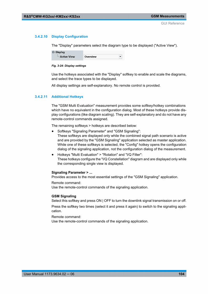
GSM MeasurementsR&S®CMW-KG2xx/-KM2xx/-KS2xx
104User Manual 1173.9634.02 ─ 06
3.4.2.10 Display Configuration
The "Display" parameters select the diagram type to be displayed ("Active View").
Fig. 3-24: Display settings
Use the hotkeys associated with the "Display" softkey to enable and scale the diagrams,and select the trace types to be displayed.
All display settings are self-explanatory. No remote control is provided.
3.4.2.11 Additional Hotkeys
The "GSM Multi Evaluation" measurement provides some softkey/hotkey combinationswhich have no equivalent in the configuration dialog. Most of these hotkeys provide dis-play configurations (like diagram scaling). They are self-explanatory and do not have anyremote-control commands assigned.
The remaining softkeys > hotkeys are described below:● Softkeys "Signaling Parameter" and "GSM Signaling":
These softkeys are displayed only while the combined signal path scenario is activeand are provided by the "GSM Signaling" application selected as master application.While one of these softkeys is selected, the "Config" hotkey opens the configurationdialog of the signaling application, not the configuration dialog of the measurement.
● Hotkeys "Multi Evaluation" > "Rotation" and "I/Q Filter":These hotkeys configure the "I/Q Constellation" diagram and are displayed only whilethe corresponding single view is displayed.
Signaling Parameter > ...Provides access to the most essential settings of the "GSM Signaling" application.
Remote command: Use the remote-control commands of the signaling application.
GSM SignalingSelect this softkey and press ON | OFF to turn the downlink signal transmission on or off.
Press the softkey two times (select it and press it again) to switch to the signaling appli-cation.
Remote command: Use the remote-control commands of the signaling application.
GUI Reference
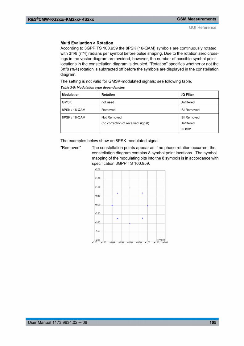
GSM MeasurementsR&S®CMW-KG2xx/-KM2xx/-KS2xx
105User Manual 1173.9634.02 ─ 06
Multi Evaluation > RotationAccording to 3GPP TS 100.959 the 8PSK (16-QAM) symbols are continuously rotatedwith 3π/8 (π/4) radians per symbol before pulse shaping. Due to the rotation zero cross-ings in the vector diagram are avoided, however, the number of possible symbol pointlocations in the constellation diagram is doubled. "Rotation" specifies whether or not the3π/8 (π/4) rotation is subtracted off before the symbols are displayed in the constellationdiagram.
The setting is not valid for GMSK-modulated signals; see following table.Table 3-5: Modulation type dependencies
Modulation Rotation I/Q Filter
GMSK not used Unfiltered
8PSK / 16-QAM Removed ISI Removed
8PSK / 16-QAM Not Removed
(no correction of received signal)
ISI Removed
Unfiltered
90 kHz
The examples below show an 8PSK-modulated signal.
"Removed" The constellation points appear as if no phase rotation occurred; theconstellation diagram contains 8 symbol point locations . The symbolmapping of the modulating bits into the 8 symbols is in accordance withspecification 3GPP TS 100.959.
GUI Reference
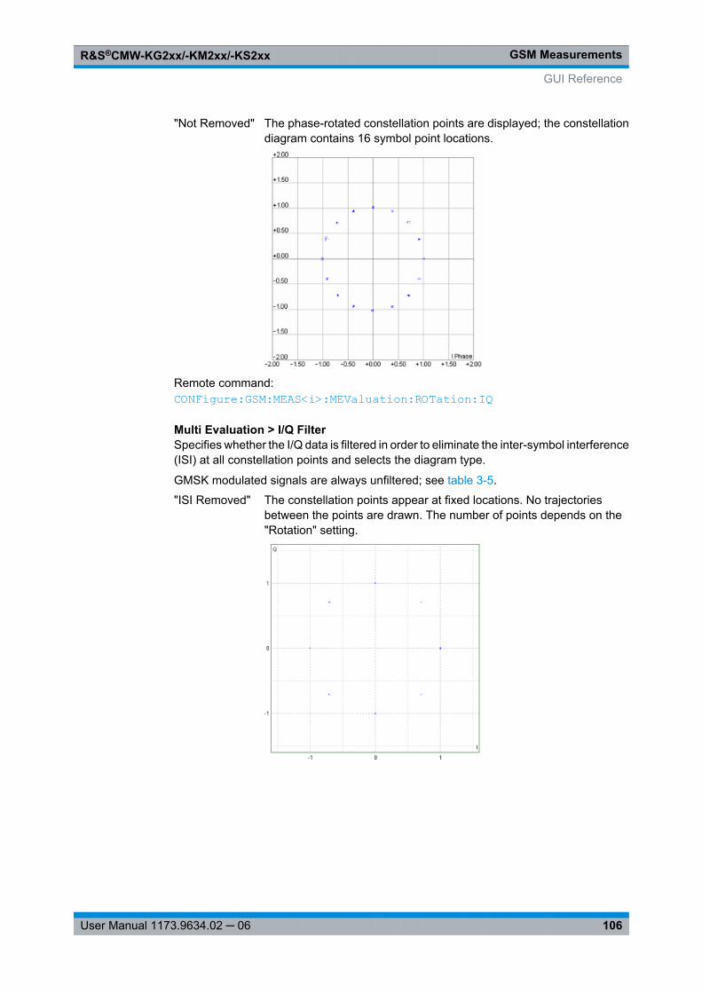
GSM MeasurementsR&S®CMW-KG2xx/-KM2xx/-KS2xx
106User Manual 1173.9634.02 ─ 06
"Not Removed" The phase-rotated constellation points are displayed; the constellationdiagram contains 16 symbol point locations.
Remote command: CONFigure: GSM: MEAS<i>: MEValuation: ROTation: IQ
Multi Evaluation > I/Q FilterSpecifies whether the I/Q data is filtered in order to eliminate the inter-symbol interference(ISI) at all constellation points and selects the diagram type.
GMSK modulated signals are always unfiltered; see table 3-5.
"ISI Removed" The constellation points appear at fixed locations. No trajectoriesbetween the points are drawn. The number of points depends on the"Rotation" setting.
GUI Reference
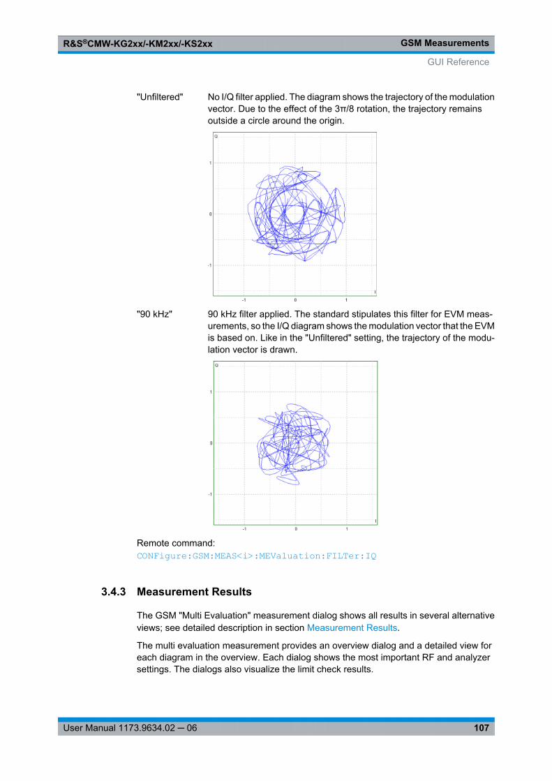
GSM MeasurementsR&S®CMW-KG2xx/-KM2xx/-KS2xx
107User Manual 1173.9634.02 ─ 06
"Unfiltered" No I/Q filter applied. The diagram shows the trajectory of the modulationvector. Due to the effect of the 3π/8 rotation, the trajectory remainsoutside a circle around the origin.
"90 kHz" 90 kHz filter applied. The standard stipulates this filter for EVM meas-urements, so the I/Q diagram shows the modulation vector that the EVMis based on. Like in the "Unfiltered" setting, the trajectory of the modu-lation vector is drawn.
Remote command: CONFigure: GSM: MEAS<i>: MEValuation: FILTer: IQ
3.4.3 Measurement Results
The GSM "Multi Evaluation" measurement dialog shows all results in several alternativeviews; see detailed description in section Measurement Results.
The multi evaluation measurement provides an overview dialog and a detailed view foreach diagram in the overview. Each dialog shows the most important RF and analyzersettings. The dialogs also visualize the limit check results.
GUI Reference
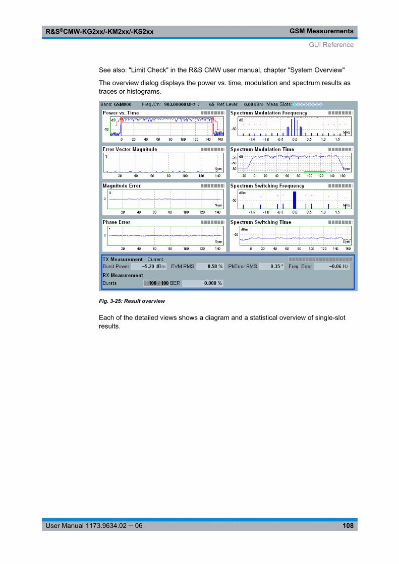
GSM MeasurementsR&S®CMW-KG2xx/-KM2xx/-KS2xx
108User Manual 1173.9634.02 ─ 06
See also: "Limit Check" in the R&S CMW user manual, chapter "System Overview"
The overview dialog displays the power vs. time, modulation and spectrum results astraces or histograms.
Fig. 3-25: Result overview
Each of the detailed views shows a diagram and a statistical overview of single-slotresults.
GUI Reference
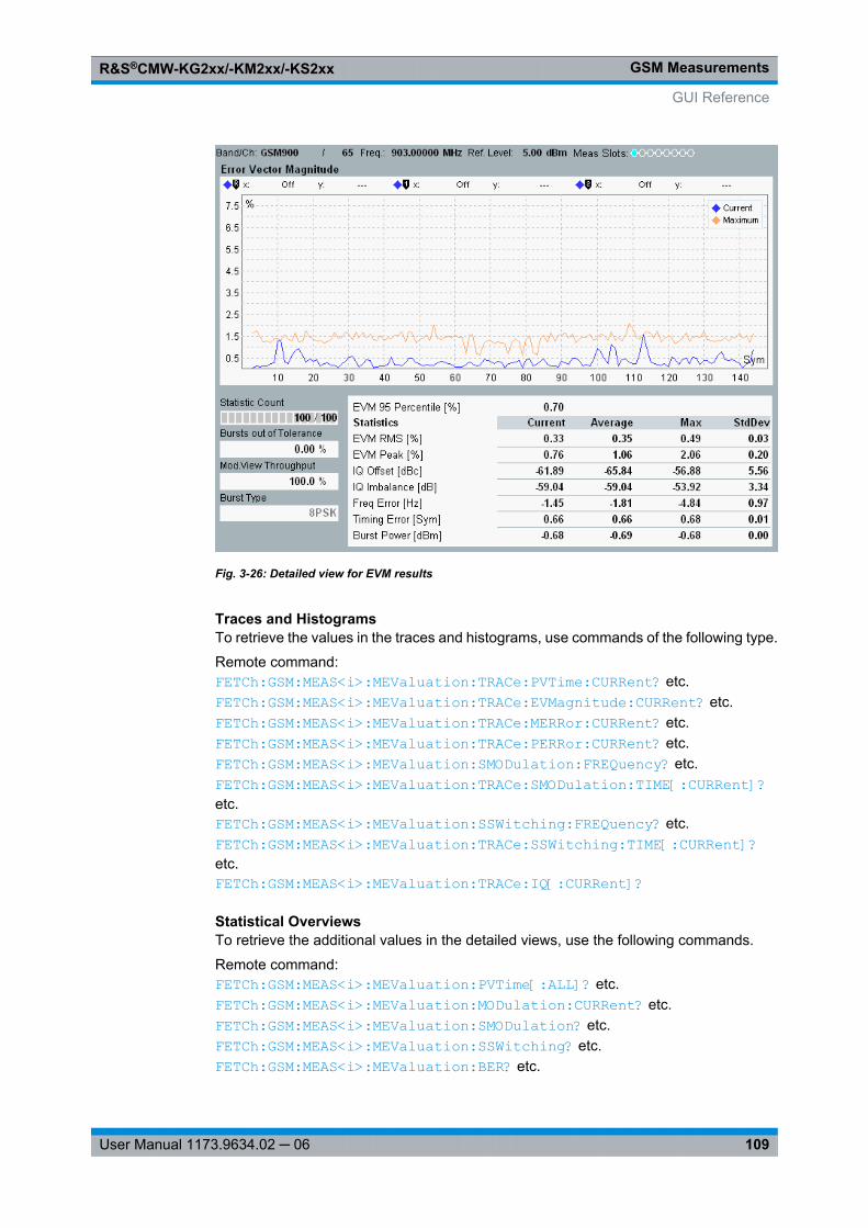
GSM MeasurementsR&S®CMW-KG2xx/-KM2xx/-KS2xx
109User Manual 1173.9634.02 ─ 06
Fig. 3-26: Detailed view for EVM results
Traces and HistogramsTo retrieve the values in the traces and histograms, use commands of the following type.
Remote command: FETCh: GSM: MEAS<i>: MEValuation: TRACe: PVTime: CURRent? etc.FETCh: GSM: MEAS<i>: MEValuation: TRACe: EVMagnitude: CURRent? etc.FETCh: GSM: MEAS<i>: MEValuation: TRACe: MERRor: CURRent? etc.FETCh: GSM: MEAS<i>: MEValuation: TRACe: PERRor: CURRent? etc.FETCh: GSM: MEAS<i>: MEValuation: SMODulation: FREQuency? etc.FETCh: GSM: MEAS<i>: MEValuation: TRACe: SMODulation: TIME[: CURRent]? etc.FETCh: GSM: MEAS<i>: MEValuation: SSWitching: FREQuency? etc.FETCh: GSM: MEAS<i>: MEValuation: TRACe: SSWitching: TIME[: CURRent]? etc.FETCh: GSM: MEAS<i>: MEValuation: TRACe: IQ[: CURRent]?
Statistical OverviewsTo retrieve the additional values in the detailed views, use the following commands.
Remote command: FETCh: GSM: MEAS<i>: MEValuation: PVTime[: ALL]? etc.FETCh: GSM: MEAS<i>: MEValuation: MODulation: CURRent? etc.FETCh: GSM: MEAS<i>: MEValuation: SMODulation? etc.FETCh: GSM: MEAS<i>: MEValuation: SSWitching? etc.FETCh: GSM: MEAS<i>: MEValuation: BER? etc.
GUI Reference
GSM MeasurementsR&S®CMW-KG2xx/-KM2xx/-KS2xx
110User Manual 1173.9634.02 ─ 06
3.5 Programming
The following sections provide programming examples for the GSM multi evaluationmeasurement.
The examples have been tested with the aid of a simple software tool.
See also: "Remote Control" in the R&S CMW user manual
● General Examples.................................................................................................110● GSM List Mode.....................................................................................................114● BER Measurement................................................................................................118● I/Q Constellation Diagram.....................................................................................118
3.5.1 General Examples
The GSM multi evaluation measurement is programmed as follows:● The measurement is controlled by SCPI commands with the following syn-
tax: ...GSM:MEAS:MEValuation...● Use general commands of the type ...:GSM:MEAS... (no :MEValuation mne-
monic) to define the signal routing and perform RF and analyzer settings.● After a *RST, the measurement is switched off. Use
READ:GSM:MEAS:MEValuation? to initiate a single-shot measurement andretrieve the results. You can also start the measurement usingINIT:GSM:MEAS:MEValuation and retrieve the results usingFETCh:GSM:MEAS:MEValuation...?.
Speed considerations
The following measurement settings provide additional results but can slow down themeasurement:● Evaluation of the spectrum vs. time measurements● Evaluation of the "AM-PM" delay for polar modulators● Access burst search
3.5.1.1 Specifying General Measurement Settings
// *************************************************************************// System-Reset// **************************************************************************RST; *OPC?*CLS; *OPC?
// *************************************************************************// Check signal routing options, perform RF and analyzer settings// for a GSM900 uplink signal (channel 1) with a// nominal power of 20 dBm and GMSK/8PSK modulation// *************************************************************************
Programming
GSM MeasurementsR&S®CMW-KG2xx/-KM2xx/-KS2xx
111User Manual 1173.9634.02 ─ 06
ROUTe:GSM:MEAS:SCENario:CSPath 'GSM Sig1'ROUTe:GSM:MEAS:SCENario:MAProtocolROUTe:GSM:MEAS:SCENario?ROUTe:GSM:MEAS?ROUTe:GSM:MEAS:SCENario:SALone RF1C, RX1
CONFigure:GSM:MEAS:RFSettings:EATTenuation 2CONFigure:GSM:MEAS:RFSettings:ENPower 20CONFigure:GSM:MEAS:RFSettings:UMARgin 5CONFigure:GSM:MEAS:RFSettings:FREQuency 890.2E+6
// *************************************************************************// Redefine the frequency entering frequency band and channel number.// *************************************************************************CONFigure:GSM:MEAS:BAND G04CONFigure:GSM:MEAS:CHANnel 300
3.5.1.2 Specifying Measurement-Specific Settings
// *************************************************************************// Select a 1.5 s timeout for the measurement.// Define statistic cycles and error handling// (no stop when tolerances are exceeded, measure on exception)// *************************************************************************CONFigure:GSM:MEAS:MEValuation:TOUT 1.5CONFigure:GSM:MEAS:MEValuation:SCOunt:PVTime 100CONFigure:GSM:MEAS:MEValuation:SCOunt:MODulation 10CONFigure:GSM:MEAS:MEValuation:SCOunt:SMODulation 10CONFigure:GSM:MEAS:MEValuation:SCOunt:SSWitching 10CONFigure:GSM:MEAS:MEValuation:SCONdition SLFailCONFigure:GSM:MEAS:MEValuation:MOEXception ON
// *************************************************************************// Specify the expected PCL values in all timeslots (for power measurements)// *************************************************************************CONFigure:GSM:MEAS:MEValuation:PCLMode PCLCONFigure:GSM:MEAS:MEValuation:PCL 5, 5, 5, 5, 5, 5, 5, 5
// *************************************************************************// Query all available trigger sources (for development)// Use a power trigger to start the measurement// Configure the instrument for a single-slot measurement in the active// timeslot detected by the trigger system, set a minimum duration// of two slots between two consecutive trigger events// *************************************************************************TRIGger:GSM:MEAS:MEValuation:CATalog:SOURce?TRIGger:GSM:MEAS:MEValuation:SOURce "POWer"TRIGger:GSM:MEAS:MEValuation:SLOPe REDGeTRIGger:GSM:MEAS:MEValuation:THReshold -2.5E+1
Programming
GSM MeasurementsR&S®CMW-KG2xx/-KM2xx/-KS2xx
112User Manual 1173.9634.02 ─ 06
TRIGger:GSM:MEAS:MEValuation:TOUT 1.0E+3CONFigure:GSM:MEAS:MEValuation:MSLots 0, 1, 0TRIGger:GSM:MEAS:MEValuation:MGAP 2
3.5.1.3 Performing Single-Shot Measurements
// *************************************************************************// Power vs. time and modulation configuration: change reference power mode// for 8PSK-modulated bursts, select a wider IF filter, decode guard and // tail bits. // Start a single-shot power vs. time measurement and return the average // burst power trace. Query the measurement status (should be "RDY" and // "RDY ,ADJ,ACT").// *************************************************************************CONFigure:GSM:MEAS:MEValuation:RPMode CURRentCONFigure:GSM:MEAS:MEValuation:FILTer:PVTime G10MCONFigure:GSM:MEAS:MEValuation:MODulation:DECode GTBitsREAD:GSM:MEAS:MEValuation:TRACe:PVTime:AVERage?
// *************************************************************************// Read the average error vector magnitude trace obtained in the// last measurement without re-starting the measurement// Query additional measurement results// *************************************************************************READ:GSM:MEAS:MEValuation:TRACe:EVMagnitude:AVERage?FETCh:GSM:MEAS:MEValuation:MVTHroughput?FETCh:GSM:MEAS:MEValuation:PVTime:BTYPe?FETCh:GSM:MEAS:MEValuation:PVTime:RSTiming?FETCh:GSM:MEAS:MEValuation:PVTime:TSC?
3.5.1.4 Single-Shot and Continuous Measurements
// *************************************************************************// Start single-shot measurement, return magnitude error trace.// Return maximum magnitude error trace and maximum phase// (without repeating the measurement. Query the measurement state// should be "RDY").// *************************************************************************INIT:GSM:MEAS:MEValuationFETCh:GSM:MEAS:MEValuation:TRACe:MERRor:MAXimum?FETCh:GSM:MEAS:MEValuation:TRACe:PERRor:MAXimum?FETCh:GSM:MEAS:MEValuation:STATe?
// *************************************************************************// Start continuous measurement; wait for 5 ms and return measurement// results of the last measured cycle.// Query measurement state and substates (should be "RUN,ADJ,ACT").// *************************************************************************CONFigure:GSM:MEAS:MEValuation:REPetition CONTinuous
Programming
GSM MeasurementsR&S®CMW-KG2xx/-KM2xx/-KS2xx
113User Manual 1173.9634.02 ─ 06
INIT:GSM:MEAS:MEValuationPause 5000FETCh:GSM:MEAS:MEValuation:MODulation:CURRent?CALCulate:GSM:MEAS:MEValuation:MODulation:CURRent?FETCh:GSM:MEAS:MEValuation:STATe:ALL?
3.5.1.5 Configuring a Spectrum Measurement
// *************************************************************************// Spectrum Modulation configuration: Define and enable five frequency// offsets, define evaluation areas// *************************************************************************CONF:GSM:MEAS:MEV:SMODulation:OFRequence 0.1e+6,0.2e+6,0.25e+6,0.4e+6, 0.6e+6,OFF,OFF,OFF,OFF,OFF,OFF,OFF,OFF,OFF,OFF,OFF,OFF,OFF,OFF,OFFCONFigure:GSM:MEAS:MEValuation:SMODulation:EARea OFF, 0, 1, ON, 90, 147
// *************************************************************************// Spectrum Switching configuration: Define and enable five offsets,// set peak hold mode for spectrum vs. frequency graphs only// *************************************************************************CONF:GSM:MEAS:MEV:SSWitching:OFRequence 0.1e+6,0.2e+6,0.25e+6,0.4e+6, 0.6e+6,OFF,OFF,OFF,OFF,OFF,OFF,OFF,OFF,OFF,OFF,OFF,OFF,OFF,OFF,OFFCONFigure:GSM:MEAS:MEValuation:SSWitching:PHMode SCO
// *************************************************************************// Re-start measurement and return spectrum results including limit check// *************************************************************************INIT:GSM:MEAS:MEValuationFETCh:GSM:MEAS:MEValuation:SMODulation:FREQuency?CALCulate:GSM:MEAS:MEValuation:SMODulation:FREQuency?FETCh:GSM:MEAS:MEValuation:SSWitching:FREQuency?CALCulate:GSM:MEAS:MEValuation:SSWitching:FREQuency?
// *************************************************************************// Enable spectrum vs. time measurements,query all enabled measurements,// define offset frequencies, retrieve measurement results// *************************************************************************CONFigure:GSM:MEAS:MEValuation:RESult:SMTime ONCONFigure:GSM:MEAS:MEValuation:RESult:SSTime ONCONFigure:GSM:MEAS:MEValuation:RESult:ALL? CONFigure:GSM:MEAS:MEValuation:SMODulation:TDFSelect 21CONFigure:GSM:MEAS:MEValuation:SSWitching:TDFSelect 22FETCh:GSM:MEAS:MEValuation:TRACe:SMODulation:TIME?FETCh:GSM:MEAS:MEValuation:TRACe:SSWitching:TIME?
3.5.1.6 Selecting Specific Burst Types
// *************************************************************************// Select only GMSK-modulated normal bursts with a definite
Programming
GSM MeasurementsR&S®CMW-KG2xx/-KM2xx/-KS2xx
114User Manual 1173.9634.02 ─ 06
// training sequence (TSC 1) and VAMOS TSC set 1. Start a single-shot// modulation measurement and return the statistical results// *************************************************************************CONFigure:GSM:MEAS:MEValuation:TSEQuence TSC1CONFigure:GSM:MEAS:MEV:MVIew GMSK, GMSK, GMSK, GMSK, GMSK, GMSK, GMSK, GMSKCONFigure:GSM:MEAS:MEValuation:VAMos:TSCSet 1READ:GSM:MEAS:MEValuation:MODulation:CURRent?CALCulate:GSM:MEAS:MEValuation:MODulation:CURRent?
// *************************************************************************// Perform a multi-slot measurement, use a frame trigger, knowing// that slots no. 5, 6, and 7 of the analyzed signal are inactive// *************************************************************************TRIGger:GSM:MEAS:MEValuation:SOURce "Acquisition"CONFigure:GSM:MEAS:MEValuation:AMODe GAPCONFigure:GSM:MEAS:MEValuation:GLENgth 3
// *************************************************************************// Perform a multi-slot measurement, use a frame trigger, knowing// that slots no. 2, 3, and 4 of the analyzed signal are 8PSK-modulated,// and that the remaining slots are inactive// *************************************************************************TRIGger:GSM:MEAS:MEValuation:SOURce "Acquisition"CONFigure:GSM:MEAS:MEValuation:AMODe PATTernCONFigure:GSM:MEAS:MEV:APATtern OFF, OFF, EPSK, EPSK, EPSK, OFF, OFF, OFF
3.5.2 GSM List Mode
The list mode for the GSM multi evaluation measurement is programmed as follows:● The measurement is controlled by SCPI commands with the following syn-
tax: ...GSM:MEAS:MEValuation:LIST...● Use general commands of the type ...:GSM:MEAS... (no :MEValuation mne-
monic) to define the signal routing and perform RF and analyzer settings.● After a *RST, the measurement is switched off and list mode is disabled. Use
CONFigure:GSM:MEAS:MEValuation:LIST ON to enable the list mode andINIT:GSM:MEAS:MEValuation to initiate a single-shot measurement.
● Use FETCh:GSM:MEAS:MEValuation:LIST:SEGMent<Seg>:...? commandsto retrieve the results.
Speed considerations
The following measurement settings have an impact on the measurement speed:● The number and size of the segments and the number of measured slots in each
segment● The number and type of results that the R&S CMW needs to calculate
Programming
GSM MeasurementsR&S®CMW-KG2xx/-KM2xx/-KS2xx
115User Manual 1173.9634.02 ─ 06
See also remarks about "Configuration of segments and measurement" in section ListMode Configuration.
3.5.2.1 Specifying General Measurement Settings
// *************************************************************************// System-Reset// **************************************************************************RST; *OPC?*CLS; *OPC?
// *************************************************************************// Define signal routing and external attenuation// (Note: The general RF frequency and expected power settings are// not used in list mode)// *************************************************************************ROUTe:GSM:MEAS:SCENario:SALone RF1C, RX1CONFigure:GSM:MEAS:RFSettings:EATTenuation 2
3.5.2.2 Specifying Measurement-Specific Settings
// *************************************************************************// Define segments, enable list mode with 2 segments and a step length// of 8 slots (one slot per TDMA frame measured).// *************************************************************************CONFigure:GSM:MEAS:MEValuation:LIST:SLENgth 8
// *************************************************************************// Define length of segments (one 52-multiframe each) and analyzer settings// *************************************************************************CONFigure:GSM:MEAS:MEValuation:PCLMode PCLCONFigure:GSM:MEAS:MEValuation:LIST:SEGMent1:SETup 52, 17, 9.04E+8, 14CONFigure:GSM:MEAS:MEValuation:LIST:SEGMent2:SETup 52, 15, 9.05E+8, 15
// *************************************************************************// Measure power in both segments, modulation and spectrum in segment 2// Select an averaging length of 52 (all measured slots in the segment)// Enable list mode// *************************************************************************CONFigure:GSM:MEAS:MEValuation:LIST:LRANge 1,2CONFigure:GSM:MEAS:MEValuation:LIST:SEGMent1:PVTime 52, ON, #B10000000CONFigure:GSM:MEAS:MEValuation:LIST:SEGMent2:PVTime 52, ON, #B10000000CONF:GSM:MEAS:MEValuation:LIST:SEGMent2:MOD 52, ON, ON, ON, ON, #B10000000CONFigure:GSM:MEAS:MEValuation:LIST:SEGMent2:SMODulation 52, ON, #B10000000CONFigure:GSM:MEAS:MEValuation:LIST:SEGMent2:SSWitching 52, ON, #B10000000CONFigure:GSM:MEAS:MEValuation:LIST ON
// *************************************************************************// Idle frames shall not cause "Signal low" errors
Programming
GSM MeasurementsR&S®CMW-KG2xx/-KM2xx/-KS2xx
116User Manual 1173.9634.02 ─ 06
// *************************************************************************CONFigure:GSM:MEAS:MEValuation:LIST:IIFRames ON
// *************************************************************************// Use a power trigger to start the measurement// *************************************************************************TRIGger:GSM:MEAS:MEValuation:SOURce 'Power'TRIGger:GSM:MEAS:MEValuation:SLOPe REDGeTRIGger:GSM:MEAS:MEValuation:THReshold -25TRIGger:GSM:MEAS:MEValuation:TOUT 1
3.5.2.3 Performing Single-Shot Measurements
// *************************************************************************// Start single-shot measurement, return current power results// (the average power in the last slot in segment 2).// Return average modulation results and spectrum results (without repeating// the measurement. Query the measurement state (should be "RDY").// *************************************************************************INIT:GSM:MEAS:MEValuationFETCh:GSM:MEAS:MEValuation:LIST:SEGMent2:PVTime:CURRent?FETCh:GSM:MEAS:MEValuation:LIST:SEGMent2:PVTime:CURRent:SVECtor? FETCh:GSM:MEAS:MEValuation:LIST:SEGMent2:MODulation:CURRent?FETCh:GSM:MEAS:MEValuation:LIST:SEGMent2:MODulation:PERCentile?FETCh:GSM:MEAS:MEValuation:LIST:SEGMent2:SMODulation?FETCh:GSM:MEAS:MEValuation:LIST:SEGMent2:SSWitching?FETCh:GSM:MEAS:MEValuation:LIST:SEGMent2:BER?FETCh:GSM:MEAS:MEValuation:STATe?
// *************************************************************************// Return list mode results in all segments// *************************************************************************FETCh:GSM:MEAS:MEValuation:LIST:PVTime:CURRent?FETCh:GSM:MEAS:MEValuation:LIST:PVTime:CURRent:SVECtor?FETCh:GSM:MEAS:MEValuation:LIST:MODulation:CURRent?FETCh:GSM:MEAS:MEValuation:LIST:MODulation:SDEViation?FETCh:GSM:MEAS:MEValuation:LIST:MODulation:PERCentile?FETCh:GSM:MEAS:MEValuation:LIST:BER?
// *************************************************************************// Return an overview of list mode results in all segments// *************************************************************************FETCh:GSM:MEAS:MEValuation:LIST:OVERview?
// *************************************************************************// Select segment no. 2 as the offline segment. Restart the measurement// to calculate all results in segment 2 and go to local to view results.// *************************************************************************CONFigure:GSM:MEAS:MEValuation:LIST:OSINdex 2
Programming
GSM MeasurementsR&S®CMW-KG2xx/-KM2xx/-KS2xx
117User Manual 1173.9634.02 ─ 06
INIT:GSM:MEAS:MEValuation>L
3.5.2.4 Retrieving Single Results for All Segments
// *************************************************************************// Return selected power vs time results// *************************************************************************FETCh:GSM:MEAS:MEValuation:LIST:PVTime:ABPower:AVERage?FETCh:GSM:MEAS:MEValuation:LIST:PVTime:SVECtor:UMAXimum:MAXimum?FETCh:GSM:MEAS:MEValuation:LIST:PVTime:SVECtor:UMINimum:AVERage?FETCh:GSM:MEAS:MEValuation:LIST:PVTime:SVECtor:SUBVector10:MINimum?
// *************************************************************************// Return selected modulation results// *************************************************************************FETCh:GSM:MEAS:MEValuation:LIST:MODulation:EVM:RMS:AVERage?FETCh:GSM:MEAS:MEValuation:LIST:MODulation:EVM:PEAK:CURRent?FETCh:GSM:MEAS:MEValuation:LIST:MODulation:EVM:PERCentile?FETCh:GSM:MEAS:MEValuation:LIST:MODulation:MERRor:RMS:AVERage?FETCh:GSM:MEAS:MEValuation:LIST:MODulation:MERRor:PEAK:AVERage?FETCh:GSM:MEAS:MEValuation:LIST:MODulation:MERRor:PERCentile?FETCh:GSM:MEAS:MEValuation:LIST:MODulation:PERRor:RMS:AVERage?FETCh:GSM:MEAS:MEValuation:LIST:MODulation:PERRor:PEAK:AVERage?FETCh:GSM:MEAS:MEValuation:LIST:MODulation:PERRor:PERCentile?FETCh:GSM:MEAS:MEValuation:LIST:MODulation:IQOFfset:AVERage?FETCh:GSM:MEAS:MEValuation:LIST:MODulation:IQIMbalance:MAXimum?FETCh:GSM:MEAS:MEValuation:LIST:MODulation:FERRor:SDEViation?FETCh:GSM:MEAS:MEValuation:LIST:MODulation:TERRor:MAXimum?FETCh:GSM:MEAS:MEValuation:LIST:MODulation:BPOWer:AVERage?FETCh:GSM:MEAS:MEValuation:LIST:MODulation:APDelay:AVERage?
// *************************************************************************// Return all BER results// *************************************************************************FETCh:GSM:MEAS:MEValuation:LIST:BER:BER?FETCh:GSM:MEAS:MEValuation:LIST:BER:ABSolute?FETCh:GSM:MEAS:MEValuation:LIST:BER:COUNt?
// *************************************************************************// Return selected spectrum due to modulation/switching results// *************************************************************************FETCh:GSM:MEAS:MEValuation:LIST:SMODulation:CPOWer?FETCh:GSM:MEAS:MEValuation:LIST:SSWitching:CPOWer?FETCh:GSM:MEAS:MEValuation:LIST:SMODulation:POFFset15?FETCh:GSM:MEAS:MEValuation:LIST:SSWitching:POFFset16?
// *************************************************************************// Return the individual segment reliability indicators
Programming

GSM MeasurementsR&S®CMW-KG2xx/-KM2xx/-KS2xx
118User Manual 1173.9634.02 ─ 06
// *************************************************************************FETCh:GSM:MEAS:MEValuation:LIST:SRELiability?
3.5.3 BER Measurement
This example focuses on the BER measurement commands. It assumes that the generalmeasurement settings have already been adjusted, see Specifying General Measure-ment Settings.
// *************************************************************************// Enable BER measurement and define a statistic count of 1000 bursts// Select a loop C measurement (for GMSK modulation), adjust thresholds// *************************************************************************CONFigure:GSM:MEAS:MEValuation:RESult:BER ONCONFigure:GSM:MEAS:MEValuation:SCOunt:BER 200CONFigure:GSM:MEAS:MEValuation:BER:LOOP CCONFigure:GSM:MEAS:MEValuation:BER:TSTart 5CONFigure:GSM:MEAS:MEValuation:BER:TRUN 30
// *************************************************************************// Start single-shot measurement, return BER results// Query the measurement state (should be "RDY").// *************************************************************************INIT:GSM:MEAS:MEValuationFETCh:GSM:MEAS:MEValuation:BER?FETCh:GSM:MEAS:MEValuation:STATe?
3.5.4 I/Q Constellation Diagram
This example focuses on the I/Q constellation diagram commands. It assumes that thegeneral measurement settings have already been adjusted, see Specifying GeneralMeasurement Settings.
// *************************************************************************// Switch on I/Q constellation diagram and define statistics cycle,// rotation and filter settings// *************************************************************************CONFigure:GSM:MEAS:MEValuation:RESult:IQ ONCONFigure:GSM:MEAS:MEValuation:SCOunt:MODulation 1CONFigure:GSM:MEAS:MEValuation:FILTer:IQ ISIRemovedCONFigure:GSM:MEAS:MEValuation:ROTation:IQ P38R
// *************************************************************************// Start single-shot measurement. Return IQ constellation results.// Query the measurement state (should be "RDY").// *************************************************************************INIT:GSM:MEAS:MEValuation
Programming
GSM MeasurementsR&S®CMW-KG2xx/-KM2xx/-KS2xx
119User Manual 1173.9634.02 ─ 06
FETCh:GSM:MEAS:MEValuation:TRACe:IQ?FETCh:GSM:MEAS:MEValuation:STATe?
3.6 Command Reference
The following sections provide detailed reference information on the remote control com-mands of the "GSM Measurements" application.
● Conventions and General Information..................................................................119● General Measurement Settings............................................................................122● Multi Evaluation Measurement Commands..........................................................128
3.6.1 Conventions and General Information
The following sections describe the most important conventions and general informationsconcerning the command reference.
3.6.1.1 MEAS<i>
MEAS<i> is used as abbreviation of "MEASurement<instance>". For better readabilityonly the abbreviated form (which is also accepted by the instrument) is given in the com-mand reference.
The <instance> is relevant for instruments supporting several instances of the samefirmware application. It can be omitted if the instrument supports only one instance, or toaddress the first instance.
See also: "Firmware Applications" in the R&S CMW user manual, chapter "Remote Con-trol"
3.6.1.2 FETCh, READ and CALCulate Commands
All commands are used to retrieve measurement results:● FETCh... returns the results of the current measurement cycle (single-shot mea-
surement) after they are valid. FETCh... must be used after the measurement hasbeen started (INITiate..., measurement states RUN or RDY).
● READ... starts a new single-shot measurement and returns the results.
● CALCulate... returns one limit check result per FETCh result:– OK: The FETCh result is located within the limits or no limit has been defined/
enabled for this result.– ULEU (User limit exceeded upper): An upper limit is violated. The FETCh result
is located above the limit.– ULEL (User limit exceeded lower): A lower limit is violated. The FETCh result is
located below the limit.
Command Reference
GSM MeasurementsR&S®CMW-KG2xx/-KM2xx/-KS2xx
120User Manual 1173.9634.02 ─ 06
See also: "Retrieving Measurement Results" in the R&S CMW user manual, chapter"Remote Control"
3.6.1.3 Current and Statistical Results
The R&S CMW repeats measurements according to the selected statistic count and rep-etition mode. Consecutive measurement values are stored and used to calculate statis-tical results, e.g. average, minimum, maximum and standard deviation.
See also: "Statistical Results" in the R&S CMW user manual, chapter "System Overview"
3.6.1.4 Reliability Indicator
The first value in the output arrays of FETCh...?, READ...? and CALCulate...?queries indicates the most severe error that has occurred during the measurement.
Example for an output array: 0, 10.22, 10.15, 10.01, 10.29, 100 (reliability = 0, followedby 5 numeric measurement values).
The reliability indicator has one of the following values:● 0 (OK):
Measurement values available, no error detected.● 1 (Measurement Timeout):
The measurement has been stopped after the (configurable) measurement timeout.Measurement results may be available, however, at least a part of the measurementprovides only INValid results or has not completed the full statistic count.
● 2 (Capture Buffer Overflow):The measurement configuration results in a capture length exceeding the availablememory.
● 3 (Overdriven) / 4 (Underdriven):The accuracy of measurement results may be impaired because the input signal levelwas too high / too low.
● 6 (Trigger Timeout):The measurement could not be started or continued because no trigger event wasdetected.
● 7 (Acquisition Error):The R&S CMW could not properly decode the RF input signal.
● 8 (Sync Error):The R&S CMW could not synchronize to the RF input signal.
● 9 (Uncal):Due to an inappropriate configuration of resolution bandwidth, video bandwidth orsweep time, the measurement results are not within the specified data sheet limits.
● 15 (Reference Frequency Error):The instrument has been configured to use an external reference signal but the ref-erence oscillator could not be phase locked to the external signal (e.g. signal leveltoo low, frequency out of range or reference signal not available at all).
● 16 (RF Not Available):
Command Reference
GSM MeasurementsR&S®CMW-KG2xx/-KM2xx/-KS2xx
121User Manual 1173.9634.02 ─ 06
The measurement could not be started because the configured RF input path wasnot active. This problem may occur e.g. when a measurement is started in combinedsignal path mode and the master application has not yet activated the input path. TheLEDs above the RF connectors indicate whether the input and output paths areactive.
● 17 (RF Level not Settled) / 18 (RF Frequency not Settled):The measurement could not be started because the R&S CMW was not yet ready todeliver stable results after a change of the input signal power / the input signal fre-quency.
● 19 (Call not Established):For measurements: The measurement could not be started because no signalingconnection to the DUT was established.For DAU IMS service: Establishing a voice over IMS call failed.
● 20 (Call Type not Usable):For measurements: The measurement could not be started because the establishedsignaling connection had wrong properties.For DAU IMS service: The voice over IMS settings could not be applied.
● 21 (Call Lost):For measurements: The measurement was interrupted because the signaling con-nection to the DUT was lost.For DAU IMS service: The voice over IMS call was lost.
● 23 (Missing Option):The ARB file can not be played by the GPRF generator due to a missing option.
● 26 (Resource Conflict):The application could not be started or has been stopped due to a conflicting hard-ware resource or software option that is allocated by another application.Please stop the application that has allocated the conflicting resources and try again.
● 27 (No Sensor Connected):The GPRF External Power Sensor measurement could not be started due to missingpower sensor.
● 40 (ARB File CRC Error):The ARB file CRC check failed. The ARB file is corrupt and not reliable.
● 42 (ARB Header Tag Invalid):The ARB file selected in the GPRF generator contains an invalid header tag.
● 43 (ARB Segment Overflow):The number of segments in the multi-segment ARB file is higher than the allowedmaximum.
● 44 (ARB File not Found):The selected ARB file could not be found.
● 50 (Startup Error):The Data Application Unit (DAU), a DAU service or a DAU measurement could notbe started. Please execute a DAU selftest.
● 51 (No Reply):The DAU has received no response, for example for a ping request.
● 52 (Connection Error):
Command Reference
GSM MeasurementsR&S®CMW-KG2xx/-KM2xx/-KS2xx
122User Manual 1173.9634.02 ─ 06
The DAU could not establish a connection to internal components. Please restart theinstrument.
● 53 (Configuration Error):The current DAU configuration by the user is incomplete or wrong and could not beapplied. Check especially the IP address configuration.
● 54 (Filesystem Error):The hard disk of the DAU is full or corrupt. Please execute a DAU selftest.
● 101 (Firmware Error):Indicates a firmware or software error. If you encounter this error for the first time,restart the instrument.If the error occurs again, consider the following hints:– Firmware errors can often be repaired by restoring the factory default settings.
To restore these settings, restart your instrument and press the "FactoryDefault" softkey during startup.
– If a software package (update) has not been properly installed this is often indi-cated in the "Setup" dialog, section "SW/HW-Equipment > Installed Software".
– A software update correcting the error may be available. Updates are e.g. provi-ded in the "CMW Customer Web" on GLORIS (registration required): https://extranet.rohde-schwarz.com.
If you get firmware errors even with the properly installed latest software version,please send a problem report including log files to Rohde & Schwarz.
● 102 (Unidentified Error):Indicates an error not covered by other reliability values. For troubleshooting pleasefollow the steps described for "101 (Firmware Error)".
● 103 (Parameter Error):Indicates that the measurement could not be performed due to internal conflictingparameter settings.A good approach to localize the conflicting settings is to start with a reset or presetor even restore the factory default settings. Then reconfigure the measurement stepby step and check when the error occurs for the first time.If you need assistance to localize the conflicting parameter settings please contactRohde & Schwarz (see http://www.service.rohde-schwarz.com).
3.6.2 General Measurement Settings
The commands valid for all GSM measurements are divided into the groups listed below.
● Signal Routing.......................................................................................................122● Analyzer Settings..................................................................................................125
3.6.2.1 Signal Routing
The following commands configure the scenario, select the connector and define anexternal attenuation value.
Command Reference
GSM MeasurementsR&S®CMW-KG2xx/-KM2xx/-KS2xx
123User Manual 1173.9634.02 ─ 06
ROUTe:GSM:MEAS<i>:SCENario: SALone .......................................................................123ROUTe:GSM:MEAS<i>:SCENario: CSPath .......................................................................123ROUTe:GSM:MEAS<i>:SCENario: MAPRotocol ................................................................124CONFigure: GSM:MEAS<i>:RFSettings: EATTenuation ......................................................124ROUTe:GSM:MEAS<i>:SCENario? .................................................................................124ROUTe:GSM:MEAS<i>? .................................................................................................125
ROUTe:GSM:MEAS<i>:SCENario:SALone <RXConnector>, <RFConverter>
Activates the standalone scenario and selects the RF input path for the measured RFsignal, i.e. the RF connector and the RX module.
Depending on the installed hardware and the active sub-instrument or instance <i> onlya subset of the described parameter values is allowed. The *RST values and the mappingof virtual connector names to physical connectors also depend on the active sub-instru-ment or instance <i>.
All instruments are equipped with the RF 1 and RF 2 connectors and one RX and TXmodule. Additional RF connectors and RX/TX modules are optionally available for R&SCMW270 and R&S CMW500, but not for R&S CMW280.
See also: "Signal Path Settings" in the R&S CMW user manual, chapter "Remote Control"
Parameters:<RXConnector> RF1C | RF2C | RF3C | RF4C | RFAC | RFBC
RF1C, RF2C, RF3C, RF4C:RF 1 COM to RF 4 COM front panel connectorsRFAC, RFBC:Virtual names for the RF COM connectors
<RFConverter> RX1 | RX2RX module for the input path
Example: See Specifying General Measurement Settings
Firmware/Software: V1.0.15.0V2.0.10: additional values RF3/4/A/B..., RX2
Manual operation: See "Scenario" on page 83
ROUTe:GSM:MEAS<i>:SCENario:CSPath <Master>
Activates the combined signal path scenario and selects a master firmware applicationfor the GSM measurements. The master controls the signal routing settings and analyzersettings while the combined signal path scenario is active.
Parameters:<Master> String parameter containing the master application, e.g.
"GSM Sig1" or "GSM Sig2"
Example: See Specifying General Measurement Settings
Firmware/Software: V1.0.15.0
Manual operation: See "Scenario" on page 83
Command Reference
GSM MeasurementsR&S®CMW-KG2xx/-KM2xx/-KS2xx
124User Manual 1173.9634.02 ─ 06
ROUTe:GSM:MEAS<i>:SCENario:MAPRotocol [<Controler>]
Activates the Measure@ProtocolTest scenario and optionally selects the controlling pro-tocol test application.
The signal routing and analyzer settings are ignored by the measurement application.The corresponding settings have to be configured within the protocol test application usedin parallel.
Setting parameters: <Controler> String parameter selecting the protocol test application
e.g. 'Protocol Test1'Example: See Specifying General Measurement Settings
Usage: Event
Firmware/Software: V1.0.15.20V2.1.60: added <Controler>
Manual operation: See "Scenario" on page 83
CONFigure:GSM:MEAS<i>:RFSettings:EATTenuation <ExternalAtt>
Defines an external attenuation (or gain, if the value is negative), to be applied to the RFinput connector.
Parameters:<ExternalAtt> Range: -50 dB to 90 dB
*RST: 0 dBDefault unit: dB
Example: See Specifying General Measurement Settings
Firmware/Software: V1.0.0.4
Manual operation: See "External Attenuation (Input)" on page 84
ROUTe:GSM:MEAS<i>:SCENario?
Queries the active scenario.
Return values: <Scenario> SALone | CSPath | MAPRotocol
Standalone, combined signal path, measure at protocol test (R&SCMW500 only)
Example: See Specifying General Measurement Settings
Usage: Query only
Firmware/Software: V2.0.10
Manual operation: See "Scenario" on page 83
Command Reference
GSM MeasurementsR&S®CMW-KG2xx/-KM2xx/-KS2xx
125User Manual 1173.9634.02 ─ 06
ROUTe:GSM:MEAS<i>?
Queries the active test scenario and connector assignment.
Return values: <Scenario> SALone | CSPath | MAPRotocol
Standalone, combined signal path, measure at protocol test (R&SCMW500 only)
<Controller> String variable containing the master application, e.g. "GSM Sig1"
<RXConnector> RF1C | RF2C | RF2I | RF3C | RF4C | RF4I | IQ1I | IQ3I | IQ5I |IQ7I | R11 | R12 | R13 | R14 | R15 | R16 | R17 | R18 | R21 | R22 |R23 | R24 | R25 | R26 | R27 | R28 | R31 | R32 | R33 | R34 | R35 |R36 | R37 | R38 | RFAC | RFBC | RFBI | RA1 | RA2 | RA3 | RA4 |RA5 | RA6 | RA7 | RA8 | RB1 | RB2 | RB3 | RB4RF 1 COM to RF 4 COM front panel connectors
<RFConverter> RX1 | RX2 | RX3 | RX4RX module for the input path
Example: See Specifying General Measurement Settings
Usage: Query only
Firmware/Software: V2.0.10
Manual operation: See "Scenario" on page 83
3.6.2.2 Analyzer Settings
The following commands configure the RF input path.
CONFigure: GSM:MEAS<i>:BAND ...................................................................................125CONFigure: GSM:MEAS<i>:CHANnel ...............................................................................126CONFigure: GSM:MEAS<i>:RFSettings: FREQuency ..........................................................126CONFigure: GSM:MEAS<i>:RFSettings: ENPower ..............................................................127CONFigure: GSM:MEAS<i>:RFSettings: UMARgin .............................................................127CONFigure: GSM:MEAS<i>:RFSettings: MLOFfset.............................................................127
CONFigure:GSM:MEAS<i>:BAND <Band>
Selects the GSM frequency band.
If the current center frequency ( CONFigure: GSM: MEAS<i>: RFSettings: FREQuency ) is valid for this frequency band, the corresponding channel number ( CONFigure: GSM: MEAS<i>: CHANnel ) is also calculated and set.
Command Reference
GSM MeasurementsR&S®CMW-KG2xx/-KM2xx/-KS2xx
126User Manual 1173.9634.02 ─ 06
Parameters:<Band> G04 | G085 | G09 | G18 | G19 | GG08
G04: GSM400G085: GSM850G09: GSM900G18: GSM1800G19: GSM1900GG08: GSMGT800*RST: G09
Example: See Specifying General Measurement Settings
Firmware/Software: V1.0.4.11
Manual operation: See "Band – Channel / Frequency" on page 85
CONFigure:GSM:MEAS<i>:CHANnel <Channel>
Selects the channel number. The channel number must be valid for the current frequencyband, for dependencies see GSM Frequency Bands and Channels.
The corresponding center frequency ( CONFigure: GSM: MEAS<i>: RFSettings: FREQuency ) is calculated and set.
Parameters:<Channel> GSM channel number
Range: depends on frequency band*RST: 65
Example: See Specifying General Measurement Settings
Firmware/Software: V1.0.4.11
Manual operation: See "Band – Channel / Frequency" on page 85
CONFigure:GSM:MEAS<i>:RFSettings:FREQuency <Frequency>
Selects the center frequency of the RF analyzer.
If the center frequency is valid for the current frequency band the corresponding channelnumber is also calculated and set.
See also:● GSM Frequency Bands and Channels● CONFigure: GSM: MEAS<i>: BAND ● CONFigure: GSM: MEAS<i>: CHANnel
Parameters:<Frequency> Range: 100E+6 Hz to 6E+9 Hz
*RST: 903E+6 HzDefault unit: Hz
Example: See Specifying General Measurement Settings
Command Reference
GSM MeasurementsR&S®CMW-KG2xx/-KM2xx/-KS2xx
127User Manual 1173.9634.02 ─ 06
Firmware/Software: V1.0.0.4
Manual operation: See "Band – Channel / Frequency" on page 85
CONFigure:GSM:MEAS<i>:RFSettings:ENPower <ExpNomPower>
Sets the expected nominal power of the measured RF signal.
Parameters:<ExpNomPower> The range of the expected nominal power can be calculated as
follows:Range (Expected Nominal Power) = Range (Input Power) + Exter-nal Attenuation - User MarginRange: –47 dBm to 55 dBm for the input power at the RF
COM connectors (please notice also the ranges quo-ted in the data sheet).
*RST: 0 dBmDefault unit: dBm
Example: See Specifying General Measurement Settings
Firmware/Software: V1.0.0.4V3.0.10: enhanced range
Manual operation: See "Expected Nominal Power" on page 85
CONFigure:GSM:MEAS<i>:RFSettings:UMARgin <UserMargin>
Sets the margin that the R&S CMW adds to the expected nominal power(CONFigure:...:MEAS<i>:RFSettings:ENPower) in order to determine its refer-ence power. The reference power minus the external input attenuation(CONFigure:...:MEAS<i>:RFSettings:EATTenuation) must be within the powerrange of the selected input connector; refer to the data sheet.
Parameters:<UserMargin> Range: 0 dB to (55 dB + External Attenuation - Expected
Nominal Power)*RST: 0 dBDefault unit: dB
Example: See Specifying General Measurement Settings
Firmware/Software: V1.0.0.4V3.0.10: enhanced range
Manual operation: See "User Margin" on page 85
CONFigure:GSM:MEAS<i>:RFSettings:MLOFfset <MixLevOffset>
Varies the input level of the mixer in the analyzer path.
Command Reference
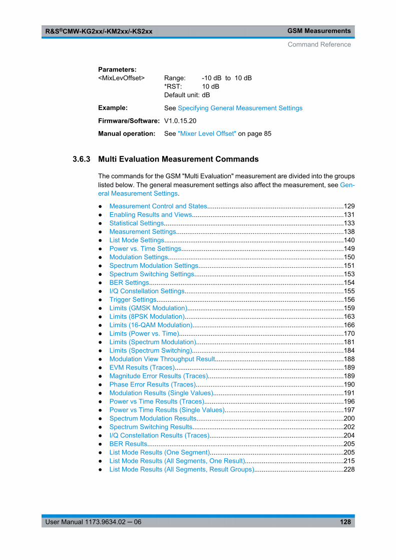
GSM MeasurementsR&S®CMW-KG2xx/-KM2xx/-KS2xx
128User Manual 1173.9634.02 ─ 06
Parameters:<MixLevOffset> Range: -10 dB to 10 dB
*RST: 10 dBDefault unit: dB
Example: See Specifying General Measurement Settings
Firmware/Software: V1.0.15.20
Manual operation: See "Mixer Level Offset" on page 85
3.6.3 Multi Evaluation Measurement Commands
The commands for the GSM "Multi Evaluation" measurement are divided into the groupslisted below. The general measurement settings also affect the measurement, see Gen-eral Measurement Settings.
● Measurement Control and States.........................................................................129● Enabling Results and Views..................................................................................131● Statistical Settings.................................................................................................133● Measurement Settings..........................................................................................138● List Mode Settings.................................................................................................140● Power vs. Time Settings.......................................................................................149● Modulation Settings...............................................................................................150● Spectrum Modulation Settings..............................................................................151● Spectrum Switching Settings................................................................................153● BER Settings.........................................................................................................154● I/Q Constellation Settings......................................................................................155● Trigger Settings.....................................................................................................156● Limits (GMSK Modulation)....................................................................................159● Limits (8PSK Modulation)......................................................................................163● Limits (16-QAM Modulation).................................................................................166● Limits (Power vs. Time).........................................................................................170● Limits (Spectrum Modulation)...............................................................................181● Limits (Spectrum Switching)..................................................................................184● Modulation View Throughput Result.....................................................................188● EVM Results (Traces)...........................................................................................189● Magnitude Error Results (Traces).........................................................................189● Phase Error Results (Traces)................................................................................190● Modulation Results (Single Values)......................................................................191● Power vs Time Results (Traces)...........................................................................196● Power vs Time Results (Single Values)................................................................197● Spectrum Modulation Results...............................................................................200● Spectrum Switching Results.................................................................................202● I/Q Constellation Results (Traces)........................................................................204● BER Results..........................................................................................................205● List Mode Results (One Segment)........................................................................205● List Mode Results (All Segments, One Result).....................................................215● List Mode Results (All Segments, Result Groups)................................................228
Command Reference
GSM MeasurementsR&S®CMW-KG2xx/-KM2xx/-KS2xx
129User Manual 1173.9634.02 ─ 06
3.6.3.1 Measurement Control and States
The following commands control the measurement and return the current measurementstate.
INITiate:GSM:MEAS<i>:MEValuation ...............................................................................129STOP:GSM:MEAS<i>:MEValuation .................................................................................129ABORt:GSM:MEAS<i>:MEValuation ................................................................................129FETCh:GSM:MEAS<i>:MEValuation: STATe?...................................................................129FETCh:GSM:MEAS<i>:MEValuation: STATe:ALL? ............................................................130
INITiate:GSM:MEAS<i>:MEValuationSTOP:GSM:MEAS<i>:MEValuationABORt:GSM:MEAS<i>:MEValuationStarts, stops, or aborts the measurement:● INITiate... starts or restarts the measurement; the R&S CMW enters the "RUN"
state.● STOP... causes a running measurement to stop after the current evaluation period
is terminated and valid results are available; the R&S CMW enters the "RDY" state.● ABORt... causes a running measurement to stop immediately; the R&S CMW
enters the "OFF" state.
Use FETCh...STATe? to query the current measurement state.
See also: "Measurement Control" in the R&S CMW user manual, chapter "Remote Con-trol"
Example: See Single-Shot and Continuous Measurements
Usage: Event
Firmware/Software: V1.0.0.4
Manual operation: See "Multi Evaluation (Softkey)" on page 82
FETCh:GSM:MEAS<i>:MEValuation:STATe?
Queries the main measurement state. Use FETCh:...:STATe:ALL? to query the mea-surement state including the substates. Use INITiate..., STOP..., ABORt...to change the measurement state.
See also: "Measurement Control" in the R&S CMW user manual, chapter "Remote Con-trol"
Command Reference
GSM MeasurementsR&S®CMW-KG2xx/-KM2xx/-KS2xx
130User Manual 1173.9634.02 ─ 06
Return values: <MeasStatus> OFF | RUN | RDY
OFF: measurement switched off, no resources allocated, noresults available (when entered after ABORt...)RUN: measurement running (after INITiate..., READ...),synchronization pending or adjusted, resources active or queuedRDY: measurement has been terminated, valid results may beavailable*RST: OFF
Example: See Single-Shot and Continuous Measurements
Usage: Query only
Firmware/Software: V1.0.0.4
Manual operation: See "Multi Evaluation (Softkey)" on page 82
FETCh:GSM:MEAS<i>:MEValuation:STATe:ALL?
Queries the main measurement state and the measurement substates. Both measure-ment substates are relevant for running measurements only. UseFETCh:...:STATe? to query the main measurement state only. Use INITiate...,STOP..., ABORt... to change the measurement state.
See also: "Measurement Control" in the R&S CMW user manual, chapter "Remote Con-trol"
Return values: <MainState> OFF | RDY | RUN
OFF: measurement switched off, no resources allocated, noresults available (when entered after STOP...)RDY: measurement has been terminated, valid results may beavailableRUN: measurement running (after INITiate..., READ...),synchronization pending or adjusted, resources active or queued*RST: OFF
<SyncState> PEND | ADJ | INVPEND: waiting for resource allocation, adjustment, hardwareswitching ("pending")ADJ: all necessary adjustments finished, measurement running("adjusted")INV: not applicable because <main_state>: OFF or RDY ("inva-lid")
Command Reference
GSM MeasurementsR&S®CMW-KG2xx/-KM2xx/-KS2xx
131User Manual 1173.9634.02 ─ 06
<ResourceState> QUE | ACT | INVQUE: measurement without resources, no results available("queued")ACT: resources allocated, acquisition of results in progress butnot complete ("active")INV: not applicable because <main_state>: OFF or RDY ("inva-lid")
Example: See Single-Shot and Continuous Measurements
Usage: Query only
Firmware/Software: V1.0.0.4
Manual operation: See "Multi Evaluation (Softkey)" on page 82
3.6.3.2 Enabling Results and Views
The following commands select the evaluated results and the displayed views.
CONFigure: GSM:MEAS<i>:MEValuation: RESult: PVTime ..................................................131CONFigure: GSM:MEAS<i>:MEValuation: RESult: EVMagnitude ..........................................131CONFigure: GSM:MEAS<i>:MEValuation: RESult: MERRor .................................................131CONFigure: GSM:MEAS<i>:MEValuation: RESult: PERRor ..................................................131CONFigure: GSM:MEAS<i>:MEValuation: RESult: IQ..........................................................131CONFigure: GSM:MEAS<i>:MEValuation: RESult: SMFRequency ........................................131CONFigure: GSM:MEAS<i>:MEValuation: RESult: SMTime ..................................................131CONFigure: GSM:MEAS<i>:MEValuation: RESult: SSFRequency .........................................131CONFigure: GSM:MEAS<i>:MEValuation: RESult: SSTime ..................................................131CONFigure: GSM:MEAS<i>:MEValuation: RESult: AMPM....................................................132CONFigure: GSM:MEAS<i>:MEValuation: RESult: MSCalar .................................................132CONFigure: GSM:MEAS<i>:MEValuation: RESult: BER .......................................................132CONFigure: GSM:MEAS<i>:MEValuation: RESult[:ALL] ......................................................132
CONFigure:GSM:MEAS<i>:MEValuation:RESult:PVTime <Enable>CONFigure:GSM:MEAS<i>:MEValuation:RESult:EVMagnitude <Enable>CONFigure:GSM:MEAS<i>:MEValuation:RESult:MERRor <Enable>CONFigure:GSM:MEAS<i>:MEValuation:RESult:PERRor <Enable>CONFigure:GSM:MEAS<i>:MEValuation:RESult:IQ <Enable>CONFigure:GSM:MEAS<i>:MEValuation:RESult:SMFRequency <Enable>CONFigure:GSM:MEAS<i>:MEValuation:RESult:SMTime <Enable>CONFigure:GSM:MEAS<i>:MEValuation:RESult:SSFRequency <Enable>CONFigure:GSM:MEAS<i>:MEValuation:RESult:SSTime <Enable>
Enables or disables the evaluation of results and shows or hides the views in the multievaluation measurement. The last mnemonic denotes the view type: Power vs. Time,Error Vector Magnitude, Magnitude Error, Phase Error, I/Q Constellation, Spectrum Mod-ulation Frequency, Spectrum Modulation Time, Spectrum Switching Frequency, Spec-trum Switching Time.
Use READ...? queries to retrieve results for disabled views.
Command Reference
GSM MeasurementsR&S®CMW-KG2xx/-KM2xx/-KS2xx
132User Manual 1173.9634.02 ─ 06
Parameters:<Enable> ON | OFF
ON: Evaluate results and show viewOFF: Do not evaluate results, hide view*RST: ON (all except MERRor, SMTime, SSTime, IQ)
Example: See Configuring a Spectrum Measurement
Firmware/Software: V1.0.0.4 (V1.0.5.3 for IQ)
Manual operation: See "Assign Views" on page 86
CONFigure:GSM:MEAS<i>:MEValuation:RESult:AMPM <Enable>CONFigure:GSM:MEAS<i>:MEValuation:RESult:MSCalar <Enable>CONFigure:GSM:MEAS<i>:MEValuation:RESult:BER <Enable>
Enables or disables the evaluation of the AM-PM results, the scalar modulation results,and the Bit Error Rate (BER).
Parameters:<Enable> ON | OFF
ON: Evaluate resultsOFF: Do not evaluate results*RST: OFF (all except MSCalar)
Example: See BER Measurement
Firmware/Software: V1.0.0.4 (V1.0.5.3 for BER)
Manual operation: See "Assign Views" on page 86
CONFigure:GSM:MEAS<i>:MEValuation:RESult[:ALL] <PvT>, <EVM>,<MagnitudeError>, <PhaseError>, <IQ>, <ACPModFrequency>,<ACPModTime>, <ACPSwitFreq>, <ACPSwitTime>, <ModScalar>, <BER>,<AMPM>
Enables or disables the evaluation of results and shows or hides the views in the multievaluation measurement. This command combines all otherCONFigure:GSM:MEAS<i>:MEValuation:RESult... commands.
Parameters:<PvT> OFF | ON
Power vs. TimeON: Evaluate results and show the viewOFF: Do not evaluate results, hide the view (if applicable)*RST: ON
<EVM> OFF | ONError Vector Magnitude*RST: ON
Command Reference
GSM MeasurementsR&S®CMW-KG2xx/-KM2xx/-KS2xx
133User Manual 1173.9634.02 ─ 06
<MagnitudeError> OFF | ONMagnitude Error*RST: OFF
<PhaseError> OFF | ONPhase Error*RST: ON
<IQ> OFF | ONI/Q Constellation*RST: OFF
<ACPModFrequency>OFF | ONACP Spectrum Modulation Frequency*RST: ON
<ACPModTime> OFF | ONACP Spectrum Modulation Time*RST: OFF
<ACPSwitFreq> OFF | ONACP Spectrum Switching Frequency*RST: ON
<ACPSwitTime> OFF | ONACP Spectrum Switching Time*RST: OFF
<ModScalar> OFF | ONScalar Modulation Results*RST: ON
<BER> OFF | ONBit Error Rate*RST: OFF
<AMPM> OFF | ONAM-PM*RST: OFF
Example: See Configuring a Spectrum Measurement
Firmware/Software: V1.0.10.1
Manual operation: See "Assign Views" on page 86
3.6.3.3 Statistical Settings
The following commands specify the scope of the measurement.
Command Reference
GSM MeasurementsR&S®CMW-KG2xx/-KM2xx/-KS2xx
134User Manual 1173.9634.02 ─ 06
CONFigure: GSM:MEAS<i>:MEValuation: TOUT................................................................134CONFigure: GSM:MEAS<i>:MEValuation: REPetition ..........................................................134CONFigure: GSM:MEAS<i>:MEValuation: SCOunt:PVTime .................................................135CONFigure: GSM:MEAS<i>:MEValuation: SCOunt:MODulation ...........................................135CONFigure: GSM:MEAS<i>:MEValuation: SCOunt:SMODulation .........................................135CONFigure: GSM:MEAS<i>:MEValuation: SCOunt:SSWitching ............................................136CONFigure: GSM:MEAS<i>:MEValuation: SCOunt:BER ......................................................136CONFigure: GSM:MEAS<i>:MEValuation: SCONdition ........................................................137CONFigure: GSM:MEAS<i>:MEValuation: MOEXception .....................................................137CONFigure: GSM:MEAS<i>:MEValuation: MSLots ..............................................................137
CONFigure:GSM:MEAS<i>:MEValuation:TOUT <Timeout>
Defines a timeout for the measurement. The timer is started when the measurement isinitiated via a READ or INIT command. It is not started if the measurement is initiatedmanually (ON/OFF key or RESTART/STOP key).
When the measurement has completed the first measurement cycle (first single shot),the statistical depth is reached and the timer is reset.
If the first measurement cycle has not been completed when the timer expires, the mea-surement is stopped. The measurement state changes to RDY and the reliability indicatoris set to 1, indicating that a measurement timeout occurred. Still running READ, FETChor CALCulate commands are completed, returning the available results. At least forsome results there are no values at all or the statistical depth has not been reached.
A timeout of 0 s corresponds to an infinite measurement timeout.
Parameters:<Timeout> Default unit: s
Example: See Specifying Measurement-Specific Settings
Firmware/Software: V2.0.10
CONFigure:GSM:MEAS<i>:MEValuation:REPetition <Repetition>
Specifies the repetition mode of the measurement. The repetition mode specifies whetherthe measurement is stopped after a single-shot or repeated continuously. UseCONFigure:..:MEAS<i>:...:SCOunt to determine the number of measurementintervals per single shot.
See also: "Statistical Settings" in the R&S CMW user manual, chapter "Remote Control"
Parameters:<Repetition> SINGleshot | CONTinuous
SINGleshot: Single-shot measurementCONTinuous: Continuous measurement*RST: SING
Example: See Single-Shot and Continuous Measurements
Firmware/Software: V1.0.0.4
Command Reference
GSM MeasurementsR&S®CMW-KG2xx/-KM2xx/-KS2xx
135User Manual 1173.9634.02 ─ 06
Manual operation: See "Repetition" on page 86
CONFigure:GSM:MEAS<i>:MEValuation:SCOunt:PVTime <StatisticCount>
Specifies the statistic count of the measurement. The statistic count is equal to the num-ber of measurement intervals per single shot. UseCONFigure:...:MEAS<i>:...:REPetition SINGleshot | CONTinuous toselect either single-shot or continuous measurements.
See also: "Statistical Settings" in the R&S CMW user manual, chapter "Remote Control"
Parameters:<StatisticCount> Number of measurement intervals for the "Power vs. Time" mea-
surementRange: 1 to 1000*RST: 10
Example: See Specifying Measurement-Specific Settings
Firmware/Software: V1.0.0.4
Manual operation: See "Statistic Count" on page 91
CONFigure:GSM:MEAS<i>:MEValuation:SCOunt:MODulation <StatisticCount>
Specifies the statistic count of the measurement. The statistic count is equal to the num-ber of measurement intervals per single shot. UseCONFigure:...:MEAS<i>:...:REPetition SINGleshot | CONTinuous toselect either single-shot or continuous measurements.
See also: "Statistical Settings" in the R&S CMW user manual, chapter "Remote Control"
Parameters:<StatisticCount> Number of measurement intervals for the "Modulation" measure-
mentRange: 1 to 1000*RST: 10
Example: See Specifying Measurement-Specific Settings
Firmware/Software: V1.0.0.4
Manual operation: See "Statistic Count" on page 94
CONFigure:GSM:MEAS<i>:MEValuation:SCOunt:SMODulation <StatisticCount>
Specifies the statistic count of the measurement. The statistic count is equal to the num-ber of measurement intervals per single shot. UseCONFigure:...:MEAS<i>:...:REPetition SINGleshot | CONTinuous toselect either single-shot or continuous measurements.
See also: "Statistical Settings" in the R&S CMW user manual, chapter "Remote Control"
Command Reference
GSM MeasurementsR&S®CMW-KG2xx/-KM2xx/-KS2xx
136User Manual 1173.9634.02 ─ 06
Parameters:<StatisticCount> Number of measurement intervals for the "Spectrum Modulation"
measurementRange: 1 to 1000*RST: 20
Example: See Specifying Measurement-Specific Settings
Firmware/Software: V1.0.0.4
Manual operation: See "Statistic Count" on page 95
CONFigure:GSM:MEAS<i>:MEValuation:SCOunt:SSWitching <StatisticCount>
Specifies the statistic count of the measurement. The statistic count is equal to the num-ber of measurement intervals per single shot. UseCONFigure:...:MEAS<i>:...:REPetition SINGleshot | CONTinuous toselect either single-shot or continuous measurements.
See also: "Statistical Settings" in the R&S CMW user manual, chapter "Remote Control"
Parameters:<StatisticCount> Number of measurement intervals for the "Spectrum Switching"
measurementRange: 1 to 100*RST: 10
Example: See Specifying Measurement-Specific Settings
Firmware/Software: V1.0.0.4
Manual operation: See "Statistic Count" on page 95
CONFigure:GSM:MEAS<i>:MEValuation:SCOunt:BER <StatisticCount>
Specifies the statistic count of the measurement. The statistic count is equal to the num-ber of measurement intervals per single shot. UseCONFigure:...:MEAS<i>:...:REPetition SINGleshot | CONTinuous toselect either single-shot or continuous measurements.
See also: "Statistical Settings" in the R&S CMW user manual, chapter "Remote Control"
Parameters:<StatisticCount> Number of measurement intervals (bursts) for the "BER" mea-
surementRange: 1 to 1000*RST: 10
Example: See BER Measurement
Firmware/Software: V1.0.5.3
Manual operation: See "Statistic Count" on page 96
Command Reference
GSM MeasurementsR&S®CMW-KG2xx/-KM2xx/-KS2xx
137User Manual 1173.9634.02 ─ 06
CONFigure:GSM:MEAS<i>:MEValuation:SCONdition <StopCondition>
Qualifies whether the measurement is stopped after a failed limit check or continued.SLFail means that the measurement is stopped and reaches the RDY state as soon asone of the results exceeds the limits.
Parameters:<StopCondition> NONE | SLFail
NONE: Continue measurement irrespective of the limit checkSLFail: Stop measurement on limit failure*RST: NONE
Example: See Specifying Measurement-Specific Settings
Firmware/Software: V1.0.0.4
Manual operation: See "Stop Condition" on page 87
CONFigure:GSM:MEAS<i>:MEValuation:MOEXception <MeasOnException>
Specifies whether measurement results that the R&S CMW identifies as faulty or inac-curate are rejected.
Parameters:<MeasOnException> ON | OFF
ON: Results are never rejectedOFF: Faulty results are rejected*RST: OFF
Example: See Specifying Measurement-Specific Settings
Firmware/Software: V1.0.0.4
Manual operation: See "Measure on Exception" on page 87
CONFigure:GSM:MEAS<i>:MEValuation:MSLots <SlotOffset>, <SlotCount>,<MeasSlot>
Defines settings for the measured slots.
Parameters:<SlotOffset> Start of the measurement interval relative to the GSM frame boun-
daryRange: 0 to 7*RST: 0
<SlotCount> Number of slots to be measuredRange: 1 to 8*RST: 1
<MeasSlot> Slot to be measured for one-slot measurementsRange: 0 to 7*RST: 0
Command Reference
GSM MeasurementsR&S®CMW-KG2xx/-KM2xx/-KS2xx
138User Manual 1173.9634.02 ─ 06
Example: See Specifying Measurement-Specific Settings
Firmware/Software: V1.0.0.4
Manual operation: See "Slot Offset" on page 87
3.6.3.4 Measurement Settings
The following commands provide general measurement settings.
CONFigure: GSM:MEAS<i>:MEValuation: FCRange ...........................................................138CONFigure: GSM:MEAS<i>:MEValuation: HDALevel ..........................................................138CONFigure: GSM:MEAS<i>:MEValuation: NBQSearch ........................................................138CONFigure: GSM:MEAS<i>:MEValuation: ABSearch ..........................................................139CONFigure: GSM:MEAS<i>:MEValuation: TSEQuence .......................................................139CONFigure: GSM:MEAS<i>:MEValuation: VAMos:TSCSet..................................................139CONFigure: GSM:MEAS<i>:MEValuation: MVIew ...............................................................140
CONFigure:GSM:MEAS<i>:MEValuation:FCRange <Mode>
Selects the width of the frequency range that the R&S CMW analyzes in order to establishtime-synchronization with the received signal.
Parameters:<Mode> NORMal | WIDE
NORMal: Normal frequency rangeWIDE: Wide frequency range*RST: NORM
Firmware/Software: V1.0.0.4
CONFigure:GSM:MEAS<i>:MEValuation:HDALevel <HighDynAssLevel>
Defines a signal level relative to the "Expected Nominal Power" ( CONFigure: GSM: MEAS<i>: RFSettings: ENPower ) where the two results obtained in a two stage mea-surement are joined together.
Parameters:<HighDynAssLevel> Range: -60 dB to -10 dB
*RST: -50 dBDefault unit: dBAdditional parameters: OFF | ON (disables | enables two-shotmeasurement)
Firmware/Software: V1.0.0.4
Manual operation: See "Two Shot Assembly Level" on page 93
CONFigure:GSM:MEAS<i>:MEValuation:NBQSearch <Enable>
Enables or disables the search for 16-QAM-modulated normal bursts.
Command Reference
GSM MeasurementsR&S®CMW-KG2xx/-KM2xx/-KS2xx
139User Manual 1173.9634.02 ─ 06
Parameters:<Enable> OFF | ON
ON: Enable 16-QAM NB searchOFF: Disable 16-QAM NB search*RST: OFF
Firmware/Software: V1.0.15.0
Options: R&S CMW-KM201
Manual operation: See "16-QAM NB Search" on page 88
CONFigure:GSM:MEAS<i>:MEValuation:ABSearch <Enable>
Enables or disables the access burst measurement.
Parameters:<Enable> OFF | ON
ON: Enable access burst searchOFF: Disable access burst search*RST: OFF
Firmware/Software: V1.0.0.4
Manual operation: See "Access Burst Search" on page 88
CONFigure:GSM:MEAS<i>:MEValuation:TSEQuence <TSC>
Selects the training sequence of the analyzed bursts.
Parameters:<TSC> OFF | TSC0 | TSC1 | TSC2 | TSC3 | TSC4 | TSC5 | TSC6 | TSC7 |
TSCA | DUMMOFF: Analyze all bursts, irrespective of their training sequenceTSC0 ... TSC7: Analyze bursts with a particular GSM trainingsequenceTSCA: Analyze bursts with any of the GSM training sequencesTSC0 to TSC7DUMMY: Analyze GSM-specific dummy bursts*RST: TSC0
Example: See Selecting Specific Burst Types
Firmware/Software: V1.0.0.4
Manual operation: See "Training Sequence" on page 88
CONFigure:GSM:MEAS<i>:MEValuation:VAMos:TSCSet <TSCset>
Specifies the expected VAMOS Training Sequence Code (TSC) set of the measuredGSM uplink signal. With a specific TSC set selection, the R&S CMW will analyze burstswith this TSC set only.
Command Reference
GSM MeasurementsR&S®CMW-KG2xx/-KM2xx/-KS2xx
140User Manual 1173.9634.02 ─ 06
Parameters:<TSCset> Range: 1 to 2
*RST: 1
Example: See Selecting Specific Burst Types
Firmware/Software: V2.0.10
Manual operation: See "GSM TSC Set (VAMOS)" on page 89
CONFigure:GSM:MEAS<i>:MEValuation:MVIew <Timeslot0>, ..., <Timeslot7>
Defines the expected modulation scheme and burst type in all timeslots and adjusts thepower/time template accordingly.
Parameters:<Timeslot0> ...<Timeslot7>
ANY | OFF | GMSK | EPSK | ACCess | Q16ANY: Any burst type can be analyzedOFF: No signal expectedGMSK: GMSK-modulated normal burstsEPSK: 8PSK-modulated normal burstsACCess: Access burstsQ16: 16-QAM-modulated normal bursts*RST: ANY
Example: See Selecting Specific Burst Types
Firmware/Software: V1.0.0.4 (Q16 in V1.0.15.0)
Options: for Q16: R&S CMW-KM201
Manual operation: See "Modulation View" on page 89
3.6.3.5 List Mode Settings
The following commands configure the list mode. For retrieving list mode results see chapter 3.6.3.30, "List Mode Results (One Segment)", on page 205, chapter 3.6.3.32,"List Mode Results (All Segments, Result Groups)", on page 228 and chapter 3.6.3.31,"List Mode Results (All Segments, One Result)", on page 215.
For a description of the list mode see chapter 3.2.3, "List Mode", on page 44.
The segment number <no> in the following commands refers to the complete range ofconfigured segments (1..2000).
CONFigure: GSM:MEAS<i>:MEValuation: LIST..................................................................141CONFigure: GSM:MEAS<i>:MEValuation: LIST:LRANge .....................................................141CONFigure: GSM:MEAS<i>:MEValuation: LIST:OSINdex ....................................................141TRIGger:GSM:MEAS<i>:MEValuation: LIST:MODE...........................................................142CONFigure: GSM:MEAS<i>:MEValuation: LIST:IIFRames...................................................142CONFigure: GSM:MEAS<i>:MEValuation: LIST:SLENgth ....................................................143CONFigure: GSM:MEAS<i>:MEValuation: LIST:SEGMent<no>: MODulation ..........................143CONFigure: GSM:MEAS<i>:MEValuation: LIST:SEGMent<no>: PVTime ...............................144CONFigure: GSM:MEAS<i>:MEValuation: LIST:SEGMent<no>: SMODulation ........................145
Command Reference
GSM MeasurementsR&S®CMW-KG2xx/-KM2xx/-KS2xx
141User Manual 1173.9634.02 ─ 06
CONFigure: GSM:MEAS<i>:MEValuation: LIST:SEGMent<no>: SSWitching ..........................146CONFigure: GSM:MEAS<i>:MEValuation: LIST:SEGMent<no>: BER ....................................146CONFigure: GSM:MEAS<i>:MEValuation: LIST:SEGMent<no>: SETup .................................147
CONFigure:GSM:MEAS<i>:MEValuation:LIST <Enable>
Enables or disables the list mode.
Parameters:<Enable> OFF | ON
ON: Enable list modeOFF: Disable list mode*RST: OFF
Example: See GSM List Mode
Firmware/Software: V1.0.4.11
Options: R&S CMW-KM012
Manual operation: See "Enable" on page 90
CONFigure:GSM:MEAS<i>:MEValuation:LIST:LRANge <StartIndex>,<NrSegments>
Select a range of measured segments. The segments must be configured using CONFigure: GSM: MEAS<i>: MEValuation: LIST: SEGMent<no>: SETup .
Parameters:<StartIndex> First measured segment in the range of configured segments
Range: 1 to 2000*RST: 1
<NrSegments> Number of measured segmentsRange: 1 to 200*RST: 10
Example: See GSM List Mode
Firmware/Software: V1.0.15.21
Options: R&S CMW-KM012
CONFigure:GSM:MEAS<i>:MEValuation:LIST:OSINdex <OfflineSegIndex>
Selects the number of the segment to be displayed in the measurement diagram. Theselected index must be within the range of measured segments ( CONFigure: GSM: MEAS<i>: MEValuation: LIST: LRANge ).
Setting a value also enables the offline mode.
Command Reference
GSM MeasurementsR&S®CMW-KG2xx/-KM2xx/-KS2xx
142User Manual 1173.9634.02 ─ 06
Parameters:<OfflineSegIndex> Range: 1 to 200
*RST: OFFAdditional parameters: OFF (disables offline mode)
Example: See GSM List Mode
Firmware/Software: V1.0.4.11
Options: R&S CMW-KM012
Manual operation: See "Offline Segment Nr." on page 90
TRIGger:GSM:MEAS<i>:MEValuation:LIST:MODE <Mode>
Specifies whether a trigger event will initiate a measurement of the entire measurementinterval (comprising the number of segments defined via CONFigure: GSM: MEAS<i>: MEValuation: LIST: LRANge ) or a measurement of single segment.
Parameters:<Mode> ONCE | SEGMent
ONCE: A trigger event is only required to start the measurement.The entire range of segments to be measured is captured withoutadditional trigger event. The retrigger flags of the segments areignored.SEGMent: The retrigger flag of each segment is evaluated. Itdefines whether the measurement waits for a trigger event beforecapturing the segment, or not.*RST: ONCE
Firmware/Software: V1.0.15.0 (retrigger mechanism changed in V2.0.10)
Options: R&S CMW-KM012
CONFigure:GSM:MEAS<i>:MEValuation:LIST:IIFRames <Ignore>
Selects whether idle frames are ignored or cause a "Signal low" error. For details see "Idle frame evaluation" on page 46.
Parameters:<Ignore> OFF | ON
*RST: OFF
Example: See GSM List Mode
Firmware/Software: V2.1.60
Manual operation: See "Ignore Idle Frames" on page 91
Command Reference
GSM MeasurementsR&S®CMW-KG2xx/-KM2xx/-KS2xx
143User Manual 1173.9634.02 ─ 06
CONFigure:GSM:MEAS<i>:MEValuation:LIST:SLENgth <StepLength>
Selects the step length, i.e. the time difference between two measured TDMA timeslots.A step length of 1 means that every slot is measured, a step length of 8 means that asingle timeslot per TDMA frame is measured.
If the step length is set to OFF, an arbitrary number of slots in each TDMA frame can bemeasured. The measured slots are defined by the <FramePattern> parameter of thefollowing commands:● CONFigure: GSM: MEAS<i>: MEValuation: LIST: SEGMent<no>: MODulation ● CONFigure: GSM: MEAS<i>: MEValuation: LIST: SEGMent<no>: PVTime ● CONFigure: GSM: MEAS<i>: MEValuation: LIST: SEGMent<no>:
SMODulation ● CONFigure: GSM: MEAS<i>: MEValuation: LIST: SEGMent<no>: SSWitching ● CONFigure: GSM: MEAS<i>: MEValuation: LIST: SEGMent<no>: BER
Parameters:<StepLength> Step length as number of TDMA slots
Range: 1 to 8*RST: 8Additional parameters: OFF (Use <FramePattern>)
Example: See GSM List Mode
Firmware/Software: V1.0.4.11 (parameter OFF: V1.0.10.1)
Options: R&S CMW-KM012
CONFigure:GSM:MEAS<i>:MEValuation:LIST:SEGMent<no>:MODulation<ModStatistics>, <EVMenable>, <MagErrorEnable>, <PhaseErrEnable>,<AMPMenable>[, <FramePattern>]
Defines the statistical length for the AVERage, MIN, and MAX calculation and enables thecalculation of the different modulation results in segment no. <no>; see List Mode.
Suffix: <no>
.1..2000Segment number
Parameters:<ModStatistics> The statistical length is defined in slots. It is limited by the number
of evaluated slots (defined via step length or frame pattern).Range: 1 to 1000*RST: 100
<EVMenable> OFF | ONON: Enable measurement of EVMOFF: Disable measurement of EVM*RST: OFF
Command Reference
GSM MeasurementsR&S®CMW-KG2xx/-KM2xx/-KS2xx
144User Manual 1173.9634.02 ─ 06
<MagErrorEnable> OFF | ONEnable or disable measurement of magnitude error*RST: OFF
<PhaseErrEnable> OFF | ONEnable or disable measurement of phase error*RST: OFF
<AMPMenable> OFF | ONEnable or disable measurement of AM PM delay*RST: OFF
<FramePattern> 8-digit binary value, defines the evaluated timeslots in each TDMAframe. Used only if no step length is configured (see CONFigure: GSM: MEAS<i>: MEValuation: LIST: SLENgth ).Range: #B00000000 to #B11111111 (no slots ... all slots
measured)*RST: #B10000000 (first slot in each frame measured)
Example: See GSM List Mode
Firmware/Software: V1.0.4.11 (parameter <FrameLength>: V1.0.10.1)
Options: R&S CMW-KM012
CONFigure:GSM:MEAS<i>:MEValuation:LIST:SEGMent<no>:PVTime <Statistic>,<Enable>[, <FramePattern>]
Defines the statistical length for averaging and enables the power vs. time measurementin segment no. <no>; see List Mode.
Suffix: <no>
.1..2000Segment number
Parameters:<Statistic> The statistical length is defined in slots. It is limited by the number
of evaluated slots (defined via step length or frame pattern).Range: 1 to 1000*RST: 1000
<Enable> OFF | ONON: Enable measurement of power vs. timeOFF: Disable measurement*RST: OFF
Command Reference
GSM MeasurementsR&S®CMW-KG2xx/-KM2xx/-KS2xx
145User Manual 1173.9634.02 ─ 06
<FramePattern> 8-digit binary value, defines the evaluated timeslots in each TDMAframe. Used only if no step length is configured (see CONFigure: GSM: MEAS<i>: MEValuation: LIST: SLENgth ).Range: #B00000000 to #B11111111 (no slots ... all slots
measured)*RST: #B10000000 (first slot in each frame measured)
Example: See GSM List Mode
Firmware/Software: V1.0.4.11 (parameter <FrameLength>: V1.0.10.1)
Options: R&S CMW-KM012
CONFigure:GSM:MEAS<i>:MEValuation:LIST:SEGMent<no>:SMODulation<Statistic>, <Enable>[, <FramePattern>]
Defines the statistical length for averaging and enables the spectrum due to modulationmeasurement in segment no. <no>; see List Mode.
Suffix: <no>
.1..2000Segment number
Parameters:<Statistic> The statistical length is defined in slots. It is limited by the number
of evaluated slots (defined via step length or frame pattern).Range: 1 to 1000*RST: 200
<Enable> OFF | ONON: Enable measurement of spectrum due to modulation results(including the "Spectrum Modulation Time" results in offline mode)OFF: Disable measurement*RST: OFF
<FramePattern> 8-digit binary value, defines the evaluated timeslots in each TDMAframe. Used only if no step length is configured (see CONFigure: GSM: MEAS<i>: MEValuation: LIST: SLENgth ).Range: #B00000000 to #B11111111 (no slots ... all slots
measured)*RST: #B10000000 (first slot in each frame measured)
Example: See GSM List Mode
Firmware/Software: V1.0.4.11 (parameter <FrameLength>: V1.0.10.1)
Options: R&S CMW-KM012
Command Reference
GSM MeasurementsR&S®CMW-KG2xx/-KM2xx/-KS2xx
146User Manual 1173.9634.02 ─ 06
CONFigure:GSM:MEAS<i>:MEValuation:LIST:SEGMent<no>:SSWitching<Statistic>, <Enable>[, <FramePattern>]
Defines the statistical length for the maximum calculation (peak hold mode) and enablesthe spectrum due to switching measurement in segment no. <no>; see List Mode.
Suffix: <no>
.1..2000Segment number
Parameters:<Statistic> The statistical length is defined in slots. It is limited by the number
of evaluated slots (defined via step length or frame pattern).Range: 1 to 100*RST: 10
<Enable> OFF | ONON: Enable measurement of spectrum due to switching (includingthe "Spectrum Switching Time" results in offline mode)OFF: Disable measurement*RST: OFF
<FramePattern> 8-digit binary value, defines the evaluated timeslots in each TDMAframe. Used only if no step length is configured (see CONFigure: GSM: MEAS<i>: MEValuation: LIST: SLENgth ).Range: #B00000000 to #B11111111 (no slots ... all slots
measured)*RST: #B10000000 (first slot in each frame measured)
Example: See GSM List Mode
Firmware/Software: V1.0.4.11 (parameter <FrameLength>: V1.0.10.1)
Options: R&S CMW-KM012
CONFigure:GSM:MEAS<i>:MEValuation:LIST:SEGMent<no>:BER <Statistic>,<Enable>, <Looptype>[, <FramePattern>]
Defines the statistical length for averaging and enables the BER measurement in seg-ment no. <no>; see List Mode.
Suffix: <no>
.1..2000Segment number
Parameters:<Statistic> The statistical length is defined in slots. It is limited by the number
of evaluated slots (defined via step length or frame pattern).Range: 1 to 100*RST: 10
Command Reference
GSM MeasurementsR&S®CMW-KG2xx/-KM2xx/-KS2xx
147User Manual 1173.9634.02 ─ 06
<Enable> OFF | ONON: Enable BER measurementOFF: Disable measurement*RST: OFF
<Looptype> C | SRBC: Loop CSRB: SRB Loop*RST: C
<FramePattern> 8-digit binary value, defines the evaluated timeslots in each TDMAframe. Used only if no step length is configured (see CONFigure: GSM: MEAS<i>: MEValuation: LIST: SLENgth ).Range: #B00000000 to #B11111111 (no slots ... all slots
measured)*RST: #B10000000 (first slot in each frame measured)
Example: See GSM List Mode
Firmware/Software: V1.0.10.1
Options: R&S CMW-KM012
CONFigure:GSM:MEAS<i>:MEValuation:LIST:SEGMent<no>:SETup<SegmentLength>, <Level>, <Frequency>[, <PCL>, <RetriggerFlag>,<EvaluatOffset>]
Defines the length, the analyzer settings, the expected PCL, retrigger setting and eval-uation offset of a selected segment. In general this command must be sent for all mea-sured segments ( CONFigure: GSM: MEAS<i>: MEValuation: LIST: LRANge ).
The PCL values are used if the global "PCL Mode: PCL" is set ( CONFigure: GSM: MEAS<i>: MEValuation: PCLMode PCL). They can affect the limit check results; see "PCL Mode" on page 93.
The current GSM band setting ( CONFigure: GSM: MEAS<i>: BAND ) specifies the exactmeaning of the PCL; see table 3-4.
Suffix: <no>
.1..2000Segment number
Command Reference
GSM MeasurementsR&S®CMW-KG2xx/-KM2xx/-KS2xx
148User Manual 1173.9634.02 ─ 06
Parameters:<SegmentLength> Number of steps or frames in the segment, depending on the con-
figured step length ( CONFigure: GSM: MEAS<i>: MEValuation: LIST: SLENgth ).If the step length is set to OFF, the segment length is defined inframes. So the number of slots in the segment equals 8 * <Seg-mentLength>.If a step length is defined (1 to 8), the segment length is definedin steps. So the number of slots in the segment equals <Step-Length> * <SegmentLength>.Range: 1 to 3000*RST: 1
<Level> Expected nominal power in the segment. The range of the expec-ted nominal power can be calculated as follows:Range (Expected Nominal Power) = Range (Input Power) + Exter-nal Attenuation - User MarginRange: -47 dBm to 55 dBm for the input power at the RF
COM connectors (please notice also the ranges quo-ted in the data sheet)
*RST: 0 dBmDefault unit: dBm
<Frequency> Range: 100E+6 Hz to 6E+9 Hz*RST: 903E+6 HzDefault unit: Hz
<PCL> Expected power control level for the segmentRange: 0 to 31*RST: 0
<RetriggerFlag> OFF | ONSpecifies whether a trigger event is required for the segment ornot. The setting is ignored for the first segment of a measurementand for trigger mode ONCE (see TRIGger: GSM: MEAS<i>: MEValuation: LIST: MODE ).OFF: measure the segment without retriggerON: wait for trigger event before measuring the segment*RST: ON
<EvaluatOffset> Number of steps at the beginning of the segment which are notmeasuredRange: 0 to 1000*RST: 0
Example: See GSM List Mode
Firmware/Software: V1.0.4.11 (parameters <PCL>, <Retrigger Flag>, <EvaluatOffset>added in V2.0.10)
Options: R&S CMW-KM012
Command Reference
GSM MeasurementsR&S®CMW-KG2xx/-KM2xx/-KS2xx
149User Manual 1173.9634.02 ─ 06
3.6.3.6 Power vs. Time Settings
The following commands configure the "Power vs. Time" measurement.
CONFigure: GSM:MEAS<i>:MEValuation: RPMode ............................................................149CONFigure: GSM:MEAS<i>:MEValuation: FILTer:PVTime ...................................................149CONFigure: GSM:MEAS<i>:MEValuation: PCLMode ..........................................................149CONFigure: GSM:MEAS<i>:MEValuation: PCL ...................................................................150
CONFigure:GSM:MEAS<i>:MEValuation:RPMode <RefPowerMode>
Defines how the reference power, i.e. the 0-dB line in the measurement diagram, is cal-culated.
Parameters:<RefPowerMode> CURRent | DCOMpensated | AVERage
DCOMpensated means "Data Compensated"*RST: AVER
Example: See Performing Single-Shot Measurements
Firmware/Software: V1.0.0.4
Manual operation: See "Reference Power Mode" on page 91
CONFigure:GSM:MEAS<i>:MEValuation:FILTer:PVTime <Filter>
Selects the bandwidth of the IF filter.
Parameters:<Filter> G05M | G10M
G05M: 500 kHz Gauss filterG10M: 1 MHz Gauss filter*RST: G05M
Example: See Performing Single-Shot Measurements
Firmware/Software: V1.0.0.4
Manual operation: See "PvT Filter" on page 92
CONFigure:GSM:MEAS<i>:MEValuation:PCLMode <PCLmode>
Defines how the R&S CMW determines the PCL of the measured signal.
Parameters:<PCLmode> AUTO | PCL
Estimated PCL (AUTO) or PCL defined via CONFigure: GSM: MEAS<i>: MEValuation: PCL *RST: AUTO
Example: See Specifying Measurement-Specific Settings
Command Reference
GSM MeasurementsR&S®CMW-KG2xx/-KM2xx/-KS2xx
150User Manual 1173.9634.02 ─ 06
Firmware/Software: V2.0.10
Manual operation: See "PCL Mode" on page 93
CONFigure:GSM:MEAS<i>:MEValuation:PCL <Slot0>, <Slot1>, <Slot2>, <Slot3>,<Slot4>, <Slot5>, <Slot6>, <Slot7>
Sets the expected PCL values in all timeslots, to be used in CONFigure: GSM: MEAS<i>: MEValuation: PCLMode on page 149 PCL. The PCL values are interpretedaccording to the current GSM band setting ( CONFigure: GSM: MEAS<i>: BAND ).
Parameters:<Slot0> Range: 0 to 31
*RST: 0
<Slot1> Range: 0 to 31*RST: 0
<Slot2> Range: 0 to 31*RST: 0
<Slot3> Range: 0 to 31*RST: 0
<Slot4> Range: 0 to 31*RST: 0
<Slot5> Range: 0 to 31*RST: 0
<Slot6> Range: 0 to 31*RST: 0
<Slot7> Range: 0 to 31*RST: 0
Example: See Specifying Measurement-Specific Settings
Firmware/Software: V2.0.10
Manual operation: See "PCL > Setting" on page 93
3.6.3.7 Modulation Settings
The following command configures the "Modulation" measurement.
CONFigure:GSM:MEAS<i>:MEValuation:MODulation:DECode <Decode>
Defines whether or not guard or tail bits are decoded.
Command Reference
GSM MeasurementsR&S®CMW-KG2xx/-KM2xx/-KS2xx
151User Manual 1173.9634.02 ─ 06
Parameters:<Decode> STANdard | GTBits
STANdard: Guard and tail bits are assumed to be in line with GSMand therefore not decoded.GTBits: Guard and tail bits are also decoded.*RST: STAN
Example: See Performing Single-Shot Measurements
Firmware/Software: V2.1.25
Manual operation: See "Decode" on page 94
3.6.3.8 Spectrum Modulation Settings
The following commands define settings for spectrum modulation frequency measure-ments.
CONFigure: GSM:MEAS<i>:MEValuation: SMODulation: OFRequence .................................151CONFigure: GSM:MEAS<i>:MEValuation: SMODulation: EARea ..........................................151CONFigure: GSM:MEAS<i>:MEValuation: SMODulation: TDFSelect .....................................152
CONFigure:GSM:MEAS<i>:MEValuation:SMODulation:OFRequence<FreqOffset0>, ..., <FreqOffset19>
Defines the frequency offsets to be used for spectrum modulation measurements. Theoffsets are defined relative to the analyzer frequency. Up to 20 offsets can be definedand enabled.
Parameters:<FreqOffset0> ...<FreqOffset19>
Set and enable frequency offset.Range: 0 Hz to 3E+6 Hz*RST: Offset 0 to 10 [MHz]: 0.1, 0.2, 0.25, 0.4, 0.6, 0.8, 1,
1.2, 1.4, 1.6, 1.8 (all ON); Offset 11 to 19: 1.9 MHz(all OFF)
Default unit: HzAdditional parameters: OFF | ON (disables offset | enables offsetusing the previous/default value)
Example: See Configuring a Spectrum Measurement
Firmware/Software: V1.0.4.11
Manual operation: See "Frequency Offsets" on page 95
CONFigure:GSM:MEAS<i>:MEValuation:SMODulation:EARea <Enable1>,<Start1>, <Stop1>, <Enable2>, <Start2>, <Stop2>
Defines the time intervals (evaluation areas) to be used for spectrum modulation meas-urements.
Command Reference
GSM MeasurementsR&S®CMW-KG2xx/-KM2xx/-KS2xx
152User Manual 1173.9634.02 ─ 06
Parameters:<Enable1> OFF | ON
ON: Enable area 1OFF: Disable area 1*RST: OFF
<Start1> Start of evaluation area 1Range: 0 Sym to 146 Sym*RST: 6 SymDefault unit: Sym
<Stop1> Stop of evaluation area 1Range: 1 Sym to 147 Sym*RST: 45 SymDefault unit: Sym
<Enable2> OFF | ONON: Enable area 2OFF: Disable area 2*RST: ON
<Start2> Start of evaluation area 2Range: 0 Sym to 146 Sym*RST: 90 SymDefault unit: Sym
<Stop2> Stop of evaluation area 2Range: 1 Sym to 147 Sym*RST: 129 SymDefault unit: Sym
Example: See Configuring a Spectrum Measurement
Firmware/Software: V1.0.0.4
Manual operation: See "Evaluation Areas" on page 95
CONFigure:GSM:MEAS<i>:MEValuation:SMODulation:TDFSelect <NrFreqOffset>
Defines the offset frequency for the "Spectrum Modulation Time" diagram. The diagramshows the measured power vs. time at the selected offset frequency.
The numbers 1 to 20 select the negative frequency offsets from the "Frequency Offsets"list, numbers 21 to 40 select the positive frequency offsets.
Parameters:<NrFreqOffset> Range: 0 to 40
*RST: 21
Example: See Configuring a Spectrum Measurement
Firmware/Software: V1.0.0.4
Manual operation: See "Time Domain @ Frequency" on page 96
Command Reference
GSM MeasurementsR&S®CMW-KG2xx/-KM2xx/-KS2xx
153User Manual 1173.9634.02 ─ 06
3.6.3.9 Spectrum Switching Settings
The following commands define settings for spectrum switching frequency measure-ments.
CONFigure: GSM:MEAS<i>:MEValuation: SSWitching: OFRequence ....................................153CONFigure: GSM:MEAS<i>:MEValuation: SSWitching: TDFSelect ........................................153CONFigure: GSM:MEAS<i>:MEValuation: SSWitching: PHMode ...........................................153
CONFigure:GSM:MEAS<i>:MEValuation:SSWitching:OFRequence<FreqOffset0>, ..., <FreqOffset19>
Defines the frequency offsets to be used for spectrum switching measurements. Theoffsets are defined relative to the analyzer frequency. Up to 20 offsets can be definedand enabled.
Parameters:<FreqOffset0> ...<FreqOffset19>
Set and enable frequency offset.Range: 0 Hz to 3E+6 Hz*RST: Offset 0 to 3 [MHz]: 0.4, 0.6, 1.2, 1.8 (all ON); Offset
4 to 19: 1.9 MHz (all OFF)Default unit: HzAdditional parameters: OFF | ON (disables offset | enables offsetusing the previous/default value)
Example: See Configuring a Spectrum Measurement
Firmware/Software: V1.0.4.11
Manual operation: See "Frequency Offsets" on page 95
CONFigure:GSM:MEAS<i>:MEValuation:SSWitching:TDFSelect <NrFreqOffset>
Defines the offset frequency for the "Spectrum Modulation Time" diagram. The diagramshows the measured power vs. time at the selected offset frequency.
The numbers 1 to 20 select the negative frequency offsets from the "Frequency Offsets"list, numbers 21 to 40 select the positive frequency offsets.
Parameters:<NrFreqOffset> Range: 0 to 40
*RST: 21
Example: See Configuring a Spectrum Measurement
Firmware/Software: V1.0.0.4
Manual operation: See "Time Domain @ Frequency" on page 96
CONFigure:GSM:MEAS<i>:MEValuation:SSWitching:PHMode <PeakHoldMode>
Specifies how the peak hold mode is used for the "Spectrum Switching" results in fre-quency domain (bar graphs) and in time domain.
Command Reference
GSM MeasurementsR&S®CMW-KG2xx/-KM2xx/-KS2xx
154User Manual 1173.9634.02 ─ 06
Parameters:<PeakHoldMode> PHOL | SCO
PHOL: Frequency and Time: Peak HoldSCO: Frequency: Stat. Count, Time: Current*RST: PHOL
Example: See Configuring a Spectrum Measurement
Firmware/Software: V1.0.0.4
Manual operation: See "Peak Hold Mode" on page 96
3.6.3.10 BER Settings
The following commands configure the "BER" measurement.
CONFigure: GSM:MEAS<i>:MEValuation: BER:LOOP........................................................154CONFigure: GSM:MEAS<i>:MEValuation: BER:TSTart.......................................................154CONFigure: GSM:MEAS<i>:MEValuation: BER:TRUN ........................................................155
CONFigure:GSM:MEAS<i>:MEValuation:BER:LOOP <Loop>
Selects the loop for BER tests.
Parameters:<Loop> C | SRB
C: Loop C (for GMSK signals, with channel coding)SRB: SRB loop (for 8PSK-modulated signals, MCS7 to MCS9)*RST: C
Example: See BER Measurement
Firmware/Software: V1.0.5.3
Manual operation: See "Loop" on page 96
CONFigure:GSM:MEAS<i>:MEValuation:BER:TSTart <ThresholdStart>
Selects the "Threshold Start" value for BER tests. This is the maximum bit error rate inthe first burst of the BER measurement.
Parameters:<ThresholdStart> Range: 0 % to 100 %
*RST: 10 %Default unit: %
Example: See BER Measurement
Firmware/Software: V1.0.10.1
Manual operation: See "Threshold Start" on page 97
Command Reference
GSM MeasurementsR&S®CMW-KG2xx/-KM2xx/-KS2xx
155User Manual 1173.9634.02 ─ 06
CONFigure:GSM:MEAS<i>:MEValuation:BER:TRUN <ThresholdRun>
Selects the "Threshold Run" value for BER tests. This is the maximum bit error rate inany burst considered for the BER measurement.
Parameters:<ThresholdRun> Range: 0 % to 100 %
*RST: 30 %Default unit: %
Example: See BER Measurement
Firmware/Software: V1.0.10.1
Manual operation: See "Threshold Run" on page 97
3.6.3.11 I/Q Constellation Settings
The following commands provide settings for the "IQ Constellation" diagram.
CONFigure: GSM:MEAS<i>:MEValuation: ROTation: IQ.......................................................155CONFigure: GSM:MEAS<i>:MEValuation: FILTer:IQ...........................................................155
CONFigure:GSM:MEAS<i>:MEValuation:ROTation:IQ <Rotation>
Specifies whether or not the rotation of the 8PSK and 16-QAM symbols is subtracted offbefore the symbols are displayed in the constellation diagram.
Parameters:<Rotation> P38 | P38R
P38: Rotation not removed, phase-rotated symbols displayedP38R: Rotation removed*RST: P38R
Example: See I/Q Constellation Diagram
Firmware/Software: V1.0.5.3
Manual operation: See "Multi Evaluation > Rotation" on page 105
CONFigure:GSM:MEAS<i>:MEValuation:FILTer:IQ <Filter>
Specifies whether the I/Q data is filtered in order to eliminate the inter-symbol interference(ISI) at all constellation points.
Parameters:<Filter> ISIRemoved | UNFiltered | F90Khz
ISIRemoved: ISI removedUNFiltered: Unfiltered dataF90Khz: 90 kHz filter*RST: ISIR
Example: See I/Q Constellation Diagram
Command Reference
GSM MeasurementsR&S®CMW-KG2xx/-KM2xx/-KS2xx
156User Manual 1173.9634.02 ─ 06
Firmware/Software: V1.0.5.3
Manual operation: See "Multi Evaluation > I/Q Filter" on page 106
3.6.3.12 Trigger Settings
The following commands define the trigger parameters.
TRIGger:GSM:MEAS<i>:MEValuation: CATalog: SOURce? .................................................156TRIGger:GSM:MEAS<i>:MEValuation: SOURce ................................................................156TRIGger:GSM:MEAS<i>:MEValuation: SLOPe ..................................................................157TRIGger:GSM:MEAS<i>:MEValuation: THReshold .............................................................157TRIGger:GSM:MEAS<i>:MEValuation: TOUT....................................................................157TRIGger:GSM:MEAS<i>:MEValuation: MGAP...................................................................158CONFigure: GSM:MEAS<i>:MEValuation: AMODe .............................................................158CONFigure: GSM:MEAS<i>:MEValuation: GLENgth ............................................................158CONFigure: GSM:MEAS<i>:MEValuation: APATtern...........................................................159
TRIGger:GSM:MEAS<i>:MEValuation:CATalog:SOURce?
Lists all trigger source values that can be set using TRIGger: GSM: MEAS<i>: MEValuation: SOURce .
Return values: <Sourcelist> Comma separated list of all supported values. Each value is rep-
resented as a string.
Example: See Specifying Measurement-Specific Settings
Usage: Query only
Firmware/Software: V1.0.4.11
Manual operation: See "Trigger Source" on page 98
TRIGger:GSM:MEAS<i>:MEValuation:SOURce <Source>
Selects the source of the trigger events. Some values are always available in this firm-ware application. They are listed below. Depending on the installed options additionalvalues may be available. A complete list of all supported values can be displayed usingTRIGger:...:CATalog:SOURce?.
Parameters:<Source> 'Power': Power trigger (received RF power)
'Acquisition': Frame trigger according to defined burst pattern'Free Run': Free Run (untriggered)'Base1: External TRIG A': External trigger fed in at TRIG A con-nector'Base1: External TRIG B': External trigger fed in at TRIG B con-nector*RST: 'Power'
Example: See Specifying Measurement-Specific Settings
Command Reference
GSM MeasurementsR&S®CMW-KG2xx/-KM2xx/-KS2xx
157User Manual 1173.9634.02 ─ 06
Firmware/Software: V1.0.4.11
Manual operation: See "Trigger Source" on page 98
TRIGger:GSM:MEAS<i>:MEValuation:SLOPe <Slope>
Qualifies whether the trigger event is generated at the rising or at the falling edge of thetrigger pulse (valid for external and power trigger sources).
Parameters:<Slope> REDGe | FEDGe
REDGe: Rising edgeFEDGe: Falling edge*RST: REDG
Example: See Specifying Measurement-Specific Settings
Firmware/Software: V1.0.4.11
Manual operation: See "Trigger Slope" on page 98
TRIGger:GSM:MEAS<i>:MEValuation:THReshold <Threshold>
Defines the trigger threshold for power trigger sources.
Parameters:<Threshold> Range: -50 dB to 0 dB
*RST: -30 dBDefault unit: dB (full scale, i.e. relative to reference level minus
external attenuation)
Example: See Specifying Measurement-Specific Settings
Firmware/Software: V1.0.4.11
Manual operation: See "Trigger Threshold" on page 99
TRIGger:GSM:MEAS<i>:MEValuation:TOUT <TriggerTimeOut>
Selects the maximum time that the R&S CMW will wait for a trigger event before it stopsthe measurement in remote control mode or indicates a trigger timeout in manual oper-ation mode. This setting has no influence on "Free Run" measurements.
Parameters:<TriggerTimeOut> Range: 0.01 s to 167.77215E+3 s
*RST: 0.1 sDefault unit: sAdditional parameters: OFF | ON (disables timeout | enables time-out using the previous/default values)
Example: See Specifying Measurement-Specific Settings
Firmware/Software: V1.0.4.11
Command Reference
GSM MeasurementsR&S®CMW-KG2xx/-KM2xx/-KS2xx
158User Manual 1173.9634.02 ─ 06
Manual operation: See "Trigger Timeout" on page 99
TRIGger:GSM:MEAS<i>:MEValuation:MGAP <MinTriggerGap>
Sets a minimum time during which the IF signal must be below the trigger threshold beforethe trigger is armed so that an IF power trigger event can be generated.
Parameters:<MinTriggerGap> Range: 1 slot to 7 slots
*RST: 1 slotDefault unit: slots
Example: See Specifying Measurement-Specific Settings
Firmware/Software: V1.0.5.3
Manual operation: See "Minimum Trigger Gap" on page 99
CONFigure:GSM:MEAS<i>:MEValuation:AMODe <AcquisitionMode>
Selects the method that the R&S CMW uses for frame synchronization.
Parameters:<AcquisitionMode> GAP | PATTern
GAP: GapPATTern: Pattern*RST: GAP
Example: See Selecting Specific Burst Types
Firmware/Software: V1.0.4.11
Manual operation: See "Acquisition > Mode" on page 100
CONFigure:GSM:MEAS<i>:MEValuation:GLENgth <GapLength>
Defines the gap length as an integer number of slots. The gap length is used for framesynchronization if the gap acquisition mode is active (see CONFigure: GSM: MEAS<i>: MEValuation: AMODe ).
Parameters:<GapLength> Range: 1 slot to 3 slots
*RST: 2 slotsDefault unit: slots
Example: See Selecting Specific Burst Types
Firmware/Software: V1.0.4.11
Manual operation: See "Acquisition > Gap Length" on page 100
Command Reference
GSM MeasurementsR&S®CMW-KG2xx/-KM2xx/-KS2xx
159User Manual 1173.9634.02 ─ 06
CONFigure:GSM:MEAS<i>:MEValuation:APATtern <Timeslot0>, ..., <Timeslot7>
Defines the burst pattern that the R&S CMW expects in the TDMA frames of the receivedGSM signal. The pattern is used for frame synchronization if the pattern acquisition modeis active (see CONFigure: GSM: MEAS<i>: MEValuation: AMODe ).
Parameters:<Timeslot0> ...<Timeslot7>
OFF | GMSK | EPSKPattern selection for corresponding timeslot (0 to 7)OFF: No signal expectedGMSK: GMSK-modulated normal burstsEPSK: 8PSK/16-QAM-modulated normal bursts*RST: GMSK (timeslot 0), OFF (timeslots 1 to 7)
Example: See Selecting Specific Burst Types
Firmware/Software: V1.0.4.11
Options: R&S CMW-KM201 (for 16-QAM modulation)
Manual operation: See "Acquisition > Pattern" on page 100
3.6.3.13 Limits (GMSK Modulation)
The following commands define limits for results which characterize the modulationaccuracy for the GMSK modulation scheme.
CONFigure: GSM:MEAS<i>:MEValuation: LIMit:GMSK:EVMagnitude ...................................159CONFigure: GSM:MEAS<i>:MEValuation: LIMit:GMSK:MERRor ..........................................160CONFigure: GSM:MEAS<i>:MEValuation: LIMit:GMSK:PERRor ...........................................161CONFigure: GSM:MEAS<i>:MEValuation: LIMit:GMSK:IQOFfset.........................................161CONFigure: GSM:MEAS<i>:MEValuation: LIMit:GMSK:IQIMbalance ....................................162CONFigure: GSM:MEAS<i>:MEValuation: LIMit:GMSK:TERRor ...........................................162CONFigure: GSM:MEAS<i>:MEValuation: LIMit:GMSK:FERRor ...........................................162
CONFigure:GSM:MEAS<i>:MEValuation:LIMit:GMSK:EVMagnitude <LimitRMS>,<LimitPeak>, <Limit95%>, <StatRMSCurrent>, <StatRMSAverage>,<StatRMSMax>, <StatPeakCurrent>, <StatPeakAverage>, <StatPeakMax>,<Stat95%>
Defines and activates upper limits for the RMS, peak and 95th percentile values of theerror vector magnitude (EVM).
Parameters:<LimitRMS> Range: 0 % to 50 %
*RST: 10 %Default unit: %
<LimitPeak> Range: 0 % to 50 %*RST: 35 %Default unit: %
Command Reference
GSM MeasurementsR&S®CMW-KG2xx/-KM2xx/-KS2xx
160User Manual 1173.9634.02 ─ 06
<Limit95%> Range: 0 % to 50 %*RST: 20 %Default unit: %
<StatRMSCurrent><StatRMSAverage><StatRMSMax><StatPeakCurrent><StatPeakAverage><StatPeakMax><Stat95%>
ON | OFFON: Apply limit to the Current, Average, Max, 95th percentile val-uesOFF: Do not apply limit*RST: OFF
Firmware/Software: V1.0.0.4
Manual operation: See "Modulation" on page 101
CONFigure:GSM:MEAS<i>:MEValuation:LIMit:GMSK:MERRor <LimitRMS>,<LimitPeak>, <Limit95%>, <StatRMSCurrent>, <StatRMSAverage>,<StatRMSMax>, <StatPeakCurrent>, <StatPeakAverage>, <StatPeakMax>,<Stat95%>
Defines and activates upper limits for the RMS, peak and 95th percentile values of themagnitude error.
Parameters:<LimitRMS> Range: 0 % to 100 %
*RST: 10 %Default unit: %
<LimitPeak> Range: 0 % to 100 %*RST: 35 %Default unit: %
<Limit95%> Range: 0 % to 100 %*RST: 20 %Default unit: %
<StatRMSCurrent><StatRMSAverage><StatRMSMax><StatPeakCurrent><StatPeakAverage><StatPeakMax><Stat95%>
ON | OFFON: Apply limit to the Current, Average, Max, 95th percentile val-uesOFF: Do not apply limit*RST: OFF
Firmware/Software: V1.0.0.4
Manual operation: See "Modulation" on page 101
Command Reference
GSM MeasurementsR&S®CMW-KG2xx/-KM2xx/-KS2xx
161User Manual 1173.9634.02 ─ 06
CONFigure:GSM:MEAS<i>:MEValuation:LIMit:GMSK:PERRor <LimitRMS>,<LimitPeak>, <Limit95%>, <StatRMSCurrent>, <StatRMSAverage>,<StatRMSMax>, <StatPeakCurrent>, <StatPeakAverage>, <StatPeakMax>,<Stat95%>
Defines and activates upper limits for the RMS, peak and 95th percentile values of thephase error.
Parameters:<LimitRMS> Range: 0 deg to 180 deg
*RST: 5 degDefault unit: deg
<LimitPeak> Range: 0 deg to 180 deg*RST: 20 degDefault unit: deg
<Limit95%> Range: 0 deg to 180 deg*RST: 10 degDefault unit: deg
<StatRMSCurrent><StatRMSAverage><StatRMSMax><StatPeakCurrent><StatPeakAverage><StatPeakMax><Stat95%>
ON | OFFON: Apply limit to the Current, Average, Max, 95th percentile val-uesOFF: Do not apply limit*RST: ON, (<Stat95%> OFF)
Firmware/Software: V1.0.0.4
Manual operation: See "Modulation" on page 101
CONFigure:GSM:MEAS<i>:MEValuation:LIMit:GMSK:IQOFfset <Limit>,<StatCurrent>, <StatAverage>, <StatMax>
Defines and activates upper limits for the I/Q origin offset values.
Parameters:<Limit> Range: -100 dB to 0 dB
*RST: -30 dBDefault unit: dB
<StatCurrent><StatAverage><StatMax>
ON | OFFON: Apply limit to the Current, Average, Max valuesOFF: Do not apply limit*RST: OFF
Firmware/Software: V1.0.0.4
Manual operation: See "Modulation" on page 101
Command Reference
GSM MeasurementsR&S®CMW-KG2xx/-KM2xx/-KS2xx
162User Manual 1173.9634.02 ─ 06
CONFigure:GSM:MEAS<i>:MEValuation:LIMit:GMSK:IQIMbalance <Limit>,<StatCurrent>, <StatAverage>, <StatMax>
Defines and activates upper limits for the I/Q imbalance values.
Parameters:<Limit> Range: -100 dB to 0 dB
*RST: -30 dBDefault unit: dB
<StatCurrent><StatAverage><StatMax>
ON | OFFON: Apply limit to the Current, Average, Max valuesOFF: Do not apply limit*RST: OFF
Firmware/Software: V1.0.0.4
Manual operation: See "Modulation" on page 101
CONFigure:GSM:MEAS<i>:MEValuation:LIMit:GMSK:TERRor <Limit>,<StatCurrent>, <StatAverage>, <StatMax>
Defines and activates upper limits for the timing error.
Parameters:<Limit> Range: -1000 Sym to 1000 Sym
*RST: 10 SymDefault unit: Sym
<StatCurrent><StatAverage><StatMax>
ON | OFFON: Apply limit to the Current, Average, Max valuesOFF: Do not apply limit*RST: OFF
Firmware/Software: V1.0.0.4
Manual operation: See "Modulation" on page 101
CONFigure:GSM:MEAS<i>:MEValuation:LIMit:GMSK:FERRor <Limit>,<StatCurrent>, <StatAverage>, <StatMax>
Defines and activates upper limits for the frequency error.
Parameters:<Limit> Range: 0 Hz to 1000 Hz
*RST: 90 HzDefault unit: Hz
<StatCurrent><StatAverage><StatMax>
ON | OFFON: Apply limit to the Current, Average, Max valuesOFF: Do not apply limit*RST: OFF
Command Reference
GSM MeasurementsR&S®CMW-KG2xx/-KM2xx/-KS2xx
163User Manual 1173.9634.02 ─ 06
Firmware/Software: V1.0.0.4
Manual operation: See "Modulation" on page 101
3.6.3.14 Limits (8PSK Modulation)
The following commands define limits for results which characterize the modulationaccuracy for the 8PSK modulation scheme.
CONFigure: GSM:MEAS<i>:MEValuation: LIMit:EPSK:EVMagnitude ....................................163CONFigure: GSM:MEAS<i>:MEValuation: LIMit:EPSK:MERRor ...........................................164CONFigure: GSM:MEAS<i>:MEValuation: LIMit:EPSK:PERRor ...........................................164CONFigure: GSM:MEAS<i>:MEValuation: LIMit:EPSK:IQOFfset..........................................165CONFigure: GSM:MEAS<i>:MEValuation: LIMit:EPSK:IQIMbalance .....................................165CONFigure: GSM:MEAS<i>:MEValuation: LIMit:EPSK:TERRor ............................................165CONFigure: GSM:MEAS<i>:MEValuation: LIMit:EPSK:FERRor ............................................166
CONFigure:GSM:MEAS<i>:MEValuation:LIMit:EPSK:EVMagnitude <LimitRMS>,<LimitPeak>, <Limit95%>, <StatRMSCurrent>, <StatRMSAverage>,<StatRMSMax>, <StatPeakCurrent>, <StatPeakAverage>, <StatPeakMax>,<Stat95%>
Defines and activates upper limits for the RMS, peak and 95th percentile values of theerror vector magnitude (EVM).
Parameters:<LimitRMS> Range: 0 % to 50 %
*RST: 9 %Default unit: %
<LimitPeak> Range: 0 % to 50 %*RST: 30 %Default unit: %
<Limit95%> Range: 0 % to 50 %*RST: 15 %Default unit: %
<StatRMSCurrent><StatRMSAverage><StatRMSMax><StatPeakCurrent><StatPeakAverage><StatPeakMax><Stat95%>
ON | OFFON: Apply limit to the Current, Average, Max, 95th percentile val-uesOFF: Do not apply limit*RST: ON
Firmware/Software: V1.0.0.4
Command Reference
GSM MeasurementsR&S®CMW-KG2xx/-KM2xx/-KS2xx
164User Manual 1173.9634.02 ─ 06
CONFigure:GSM:MEAS<i>:MEValuation:LIMit:EPSK:MERRor <LimitRMS>,<LimitPeak>, <Limit95%>, <StatRMSCurrent>, <StatRMSAverage>,<StatRMSMax>, <StatPeakCurrent>, <StatPeakAverage>, <StatPeakMax>,<Stat95%>
Defines and activates upper limits for the RMS, peak and 95th percentile values of themagnitude error.
Parameters:<LimitRMS> Range: 0 % to 100 %
*RST: 9 %Default unit: %
<LimitPeak> Range: 0 % to 100 %*RST: 30 %Default unit: %
<Limit95%> Range: 0 % to 100 %*RST: 15 %Default unit: %
<StatRMSCurrent><StatRMSAverage><StatRMSMax><StatPeakCurrent><StatPeakAverage><StatPeakMax><Stat95%>
ON | OFFON: Apply limit to the Current, Average, Max, 95th percentile val-uesOFF: Do not apply limit*RST: OFF
Firmware/Software: V1.0.0.4
CONFigure:GSM:MEAS<i>:MEValuation:LIMit:EPSK:PERRor <LimitRMS>,<LimitPeak>, <Limit95%>, <StatRMSCurrent>, <StatRMSAverage>,<StatRMSMax>, <StatPeakCurrent>, <StatPeakAverage>, <StatPeakMax>,<Stat95%>
Defines and activates upper limits for the RMS, peak and 95th percentile values of thephase error.
Parameters:<LimitRMS> Range: 0 deg to 180 deg
*RST: 5 degDefault unit: deg
<LimitPeak> Range: 0 deg to 180 deg*RST: 20 degDefault unit: deg
<Limit95%> Range: 0 deg to 180 deg*RST: 10 degDefault unit: deg
Command Reference
GSM MeasurementsR&S®CMW-KG2xx/-KM2xx/-KS2xx
165User Manual 1173.9634.02 ─ 06
<StatRMSCurrent><StatRMSAverage><StatRMSMax><StatPeakCurrent><StatPeakAverage><StatPeakMax><Stat95%>
ON | OFFON: Apply limit to the Current, Average, Max, 95th percentile val-uesOFF: Do not apply limit*RST: OFF
Firmware/Software: V1.0.0.4
CONFigure:GSM:MEAS<i>:MEValuation:LIMit:EPSK:IQOFfset <Limit>,<StatCurrent>, <StatAverage>, <StatMax>
Defines and activates upper limits for the I/Q origin offset values.
Parameters:<Limit> Range: -100 dB to 0 dB
*RST: -30 dBDefault unit: dB
<StatCurrent><StatAverage><StatMax>
ON | OFFON: Apply limit to the Current, Average, Max valuesOFF: Do not apply limit*RST: OFF (ON for Average)
Firmware/Software: V1.0.0.4
CONFigure:GSM:MEAS<i>:MEValuation:LIMit:EPSK:IQIMbalance <Limit>,<StatCurrent>, <StatAverage>, <StatMax>
Defines and activates upper limits for the I/Q imbalance values.
Parameters:<Limit> Range: -100 dB to 0 dB
*RST: -30 dBDefault unit: dB
<StatCurrent><StatAverage><StatMax>
ON | OFFON: Apply limit to the Current, Average, Max valuesOFF: Do not apply limit*RST: OFF (ON for Average)
Firmware/Software: V1.0.0.4
CONFigure:GSM:MEAS<i>:MEValuation:LIMit:EPSK:TERRor <Limit>,<StatCurrent>, <StatAverage>, <StatMax>
Defines and activates upper limits for the timing error.
Command Reference
GSM MeasurementsR&S®CMW-KG2xx/-KM2xx/-KS2xx
166User Manual 1173.9634.02 ─ 06
Parameters:<Limit> Range: -1000 Sym to 1000 Sym
*RST: 10 SymDefault unit: Sym
<StatCurrent><StatAverage><StatMax>
ON | OFFON: Apply limit to the Current, Average, Max valuesOFF: Do not apply limit*RST: OFF
Firmware/Software: V1.0.0.4
CONFigure:GSM:MEAS<i>:MEValuation:LIMit:EPSK:FERRor <Limit>,<StatCurrent>, <StatAverage>, <StatMax>
Defines and activates upper limits for the frequency error.
Parameters:<Limit> Range: 0 Hz to 1000 Hz
*RST: 90 HzDefault unit: Hz
<StatCurrent><StatAverage><StatMax>
ON | OFFON: Apply limit to the Current, Average, Max valuesOFF: Do not apply limit*RST: ON
Firmware/Software: V1.0.0.4
3.6.3.15 Limits (16-QAM Modulation)
The following commands define limits for results which characterize the modulationaccuracy for the 16-QAM modulation scheme.
CONFigure: GSM:MEAS<i>:MEValuation: LIMit:QAM<ModOrder>: EVMagnitude ...................166CONFigure: GSM:MEAS<i>:MEValuation: LIMit:QAM<ModOrder>: MERRor ..........................167CONFigure: GSM:MEAS<i>:MEValuation: LIMit:QAM<ModOrder>: PERRor ..........................168CONFigure: GSM:MEAS<i>:MEValuation: LIMit:QAM<ModOrder>: IQOFfset.........................168CONFigure: GSM:MEAS<i>:MEValuation: LIMit:QAM<ModOrder>: IQIMbalance ....................169CONFigure: GSM:MEAS<i>:MEValuation: LIMit:QAM<ModOrder>: TERRor ...........................169CONFigure: GSM:MEAS<i>:MEValuation: LIMit:QAM<ModOrder>: FERRor ...........................170
CONFigure:GSM:MEAS<i>:MEValuation:LIMit:QAM<ModOrder>:EVMagnitude<LimitRMS>, <LimitPeak>, <Limit95%>, <StatRMSCurrent>,<StatRMSAverage>, <StatRMSMax>, <StatPeakCurrent>, <StatPeakAverage>,<StatPeakMax>, <Stat95%>
Defines and activates upper limits for the RMS, peak and 95th percentile values of theerror vector magnitude (EVM).
Command Reference
GSM MeasurementsR&S®CMW-KG2xx/-KM2xx/-KS2xx
167User Manual 1173.9634.02 ─ 06
Suffix: <ModOrder>
.16Modulation order, at present fixed
Parameters:<LimitRMS> Range: 0 % to 50 %
*RST: 7 %Default unit: %
<LimitPeak> Range: 0 % to 50 %*RST: 30 %Default unit: %
<Limit95%> Range: 0 % to 50 %*RST: 15 %Default unit: %
<StatRMSCurrent><StatRMSAverage><StatRMSMax><StatPeakCurrent><StatPeakAverage><StatPeakMax><Stat95%>
ON | OFFON: Apply limit to the Current, Average, Max, 95th percentile val-uesOFF: Do not apply limit*RST: ON
Firmware/Software: V1.0.15.0
Options: R&S CMW-KM201 (for QAM16)
CONFigure:GSM:MEAS<i>:MEValuation:LIMit:QAM<ModOrder>:MERRor<LimitRMS>, <LimitPeak>, <Limit95%>, <StatRMSCurrent>,<StatRMSAverage>, <StatRMSMax>, <StatPeakCurrent>, <StatPeakAverage>,<StatPeakMax>, <Stat95%>
Defines and activates upper limits for the RMS, peak and 95th percentile values of themagnitude error.
Suffix: <ModOrder>
.16Modulation order, at present fixed
Parameters:<LimitRMS> Range: 0 % to 100 %
*RST: 7 %Default unit: %
<LimitPeak> Range: 0 % to 100 %*RST: 30 %Default unit: %
<Limit95%> Range: 0 % to 100 %*RST: 15 %Default unit: %
Command Reference
GSM MeasurementsR&S®CMW-KG2xx/-KM2xx/-KS2xx
168User Manual 1173.9634.02 ─ 06
<StatRMSCurrent><StatRMSAverage><StatRMSMax><StatPeakCurrent><StatPeakAverage><StatPeakMax><Stat95%>
ON | OFFON: Apply limit to the Current, Average, Max, 95th percentile val-uesOFF: Do not apply limit*RST: OFF
Firmware/Software: V1.0.15.0
Options: R&S CMW-KM201 (for QAM16)
CONFigure:GSM:MEAS<i>:MEValuation:LIMit:QAM<ModOrder>:PERRor<LimitRMS>, <LimitPeak>, <Limit95%>, <StatRMSCurrent>,<StatRMSAverage>, <StatRMSMax>, <StatPeakCurrent>, <StatPeakAverage>,<StatPeakMax>, <Stat95%>
Defines and activates upper limits for the RMS, peak and 95th percentile values of thephase error.
Suffix: <ModOrder>
.16Modulation order, at present fixed
Parameters:<LimitRMS> Range: 0 deg to 180 deg
*RST: 5 degDefault unit: deg
<LimitPeak> Range: 0 deg to 180 deg*RST: 20 degDefault unit: deg
<Limit95%> Range: 0 deg to 180 deg*RST: 10 degDefault unit: deg
<StatRMSCurrent><StatRMSAverage><StatRMSMax><StatPeakCurrent><StatPeakAverage><StatPeakMax><Stat95%>
ON | OFFON: Apply limit to the Current, Average, Max, 95th percentile val-uesOFF: Do not apply limit*RST: OFF
Firmware/Software: V1.0.15.0
Options: R&S CMW-KM201 (for QAM16)
CONFigure:GSM:MEAS<i>:MEValuation:LIMit:QAM<ModOrder>:IQOFfset <Limit>,<StatCurrent>, <StatAverage>, <StatMax>
Defines and activates upper limits for the I/Q origin offset values.
Command Reference
GSM MeasurementsR&S®CMW-KG2xx/-KM2xx/-KS2xx
169User Manual 1173.9634.02 ─ 06
Suffix: <ModOrder>
.16Modulation order, at present fixed
Parameters:<Limit> Range: -100 dB to 0 dB
*RST: -30 dBDefault unit: dB
<StatCurrent><StatAverage><StatMax>
ON | OFFON: Apply limit to the Current, Average, Max valuesOFF: Do not apply limit*RST: OFF (ON for Average)
Firmware/Software: V1.0.15.0
Options: R&S CMW-KM201 (for QAM16)
CONFigure:GSM:MEAS<i>:MEValuation:LIMit:QAM<ModOrder>:IQIMbalance<Limit>, <StatCurrent>, <StatAverage>, <StatMax>
Defines and activates upper limits for the I/Q imbalance values.
Suffix: <ModOrder>
.16Modulation order, at present fixed
Parameters:<Limit> Range: -100 dB to 0 dB
*RST: -30 dBDefault unit: dB
<StatCurrent><StatAverage><StatMax>
ON | OFFON: Apply limit to the Current, Average, Max valuesOFF: Do not apply limit*RST: OFF (ON for Average)
Firmware/Software: V1.0.15.0
Options: R&S CMW-KM201 (for QAM16)
CONFigure:GSM:MEAS<i>:MEValuation:LIMit:QAM<ModOrder>:TERRor <Limit>,<StatCurrent>, <StatAverage>, <StatMax>
Defines and activates upper limits for the timing error.
Suffix: <ModOrder>
.16Modulation order, at present fixed
Command Reference
GSM MeasurementsR&S®CMW-KG2xx/-KM2xx/-KS2xx
170User Manual 1173.9634.02 ─ 06
Parameters:<Limit> Range: -1000 Sym to 1000 Sym
*RST: 10 SymDefault unit: Sym
<StatCurrent><StatAverage><StatMax>
ON | OFFON: Apply limit to the Current, Average, Max valuesOFF: Do not apply limit*RST: OFF
Firmware/Software: V1.0.15.0
Options: R&S CMW-KM201 (for QAM16)
CONFigure:GSM:MEAS<i>:MEValuation:LIMit:QAM<ModOrder>:FERRor <Limit>,<StatCurrent>, <StatAverage>, <StatMax>
Defines and activates upper limits for the frequency error.
Suffix: <ModOrder>
.16Modulation order, at present fixed
Parameters:<Limit> Range: 0 Hz to 1000 Hz
*RST: 90 HzDefault unit: Hz
<StatCurrent><StatAverage><StatMax>
ON | OFFON: Apply limit to the Current, Average, Max valuesOFF: Do not apply limit*RST: ON
Firmware/Software: V1.0.15.0
Options: R&S CMW-KM201 (for QAM16)
3.6.3.16 Limits (Power vs. Time)
The following commands define limit lines for power vs. time measurements.
CONFigure: GSM:MEAS<i>:MEValuation: LIMit:PVTime:ABPower<no> ................................171CONFigure: GSM:MEAS<i>:MEValuation: LIMit:PVTime:GPLevel ........................................172CONFigure: GSM:MEAS<i>:MEValuation: LIMit:GMSK:PVTime:UPPer: REDGe<no>:
STATic...............................................................................................................173CONFigure: GSM:MEAS<i>:MEValuation: LIMit:GMSK:PVTime:UPPer: UPARt<no>:
STATic...............................................................................................................173CONFigure: GSM:MEAS<i>:MEValuation: LIMit:GMSK:PVTime:UPPer: FEDGe<no>:
STATic...............................................................................................................173CONFigure: GSM:MEAS<i>:MEValuation: LIMit:EPSK:PVTime:UPPer: REDGe<no>:
STATic...............................................................................................................173
Command Reference
GSM MeasurementsR&S®CMW-KG2xx/-KM2xx/-KS2xx
171User Manual 1173.9634.02 ─ 06
CONFigure: GSM:MEAS<i>:MEValuation: LIMit:EPSK:PVTime:UPPer: UPARt<no>: STATic...............................................................................................................173
CONFigure: GSM:MEAS<i>:MEValuation: LIMit:EPSK:PVTime:UPPer: FEDGe<no>: STATic...............................................................................................................173
CONFigure: GSM:MEAS<i>:MEValuation: LIMit:QAM<ModOrder>: PVTime:UPPer: REDGe<no>: STATic............................................................................................173
CONFigure: GSM:MEAS<i>:MEValuation: LIMit:QAM<ModOrder>: PVTime:UPPer: UPARt<no>: STATic.............................................................................................173
CONFigure: GSM:MEAS<i>:MEValuation: LIMit:QAM<ModOrder>: PVTime:UPPer: FEDGe<no>: STATic............................................................................................173
CONFigure: GSM:MEAS<i>:MEValuation: LIMit:GMSK:PVTime:LOWer:UPARt<no>: STATic...............................................................................................................176
CONFigure: GSM:MEAS<i>:MEValuation: LIMit:EPSK:PVTime:LOWer:UPARt<no>: STATic...............................................................................................................176
CONFigure: GSM:MEAS<i>:MEValuation: LIMit:QAM<ModOrder>: PVTime:LOWer:UPARt<no>: STATic.............................................................................................176
CONFigure: GSM:MEAS<i>:MEValuation: LIMit:GMSK:PVTime:UPPer: REDGe<no>: DYNamic<Range> ...............................................................................................178
CONFigure: GSM:MEAS<i>:MEValuation: LIMit:EPSK:PVTime:UPPer: REDGe<no>: DYNamic<Range> ...............................................................................................178
CONFigure: GSM:MEAS<i>:MEValuation: LIMit:QAM<ModOrder>: PVTime:UPPer: REDGe<no>: DYNamic<Range> ............................................................................178
CONFigure: GSM:MEAS<i>:MEValuation: LIMit:GMSK:PVTime:UPPer: UPARt<no>: DYNamic<Range> ...............................................................................................178
CONFigure: GSM:MEAS<i>:MEValuation: LIMit:EPSK:PVTime:UPPer: UPARt<no>: DYNamic<Range> ...............................................................................................178
CONFigure: GSM:MEAS<i>:MEValuation: LIMit:QAM<ModOrder>: PVTime:UPPer: UPARt<no>: DYNamic<Range> .............................................................................178
CONFigure: GSM:MEAS<i>:MEValuation: LIMit:GMSK:PVTime:UPPer: FEDGe<no>: DYNamic<Range> ...............................................................................................178
CONFigure: GSM:MEAS<i>:MEValuation: LIMit:EPSK:PVTime:UPPer: FEDGe<no>: DYNamic<Range> ...............................................................................................179
CONFigure: GSM:MEAS<i>:MEValuation: LIMit:QAM<ModOrder>: PVTime:UPPer: FEDGe<no>: DYNamic<Range> ............................................................................179
CONFigure: GSM:MEAS<i>:MEValuation: LIMit:GMSK:PVTime:LOWer:UPARt<no>: DYNamic<Range> ...............................................................................................180
CONFigure: GSM:MEAS<i>:MEValuation: LIMit:EPSK:PVTime:LOWer:UPARt<no>: DYNamic<Range> ...............................................................................................180
CONFigure: GSM:MEAS<i>:MEValuation: LIMit:QAM<ModOrder>: PVTime:LOWer:UPARt<no>: DYNamic<Range> .............................................................................180
CONFigure:GSM:MEAS<i>:MEValuation:LIMit:PVTime:ABPower<no> <StartPCL>,<EndPCL>, <LowerLimit>, <UpperLimit>, <Enable>
Defines and activates limits for the average burst power, i.e. tolerances for ranges oftemplate power control levels (TPCLs).
Suffix: <no>
.1..10Number of the group
Command Reference
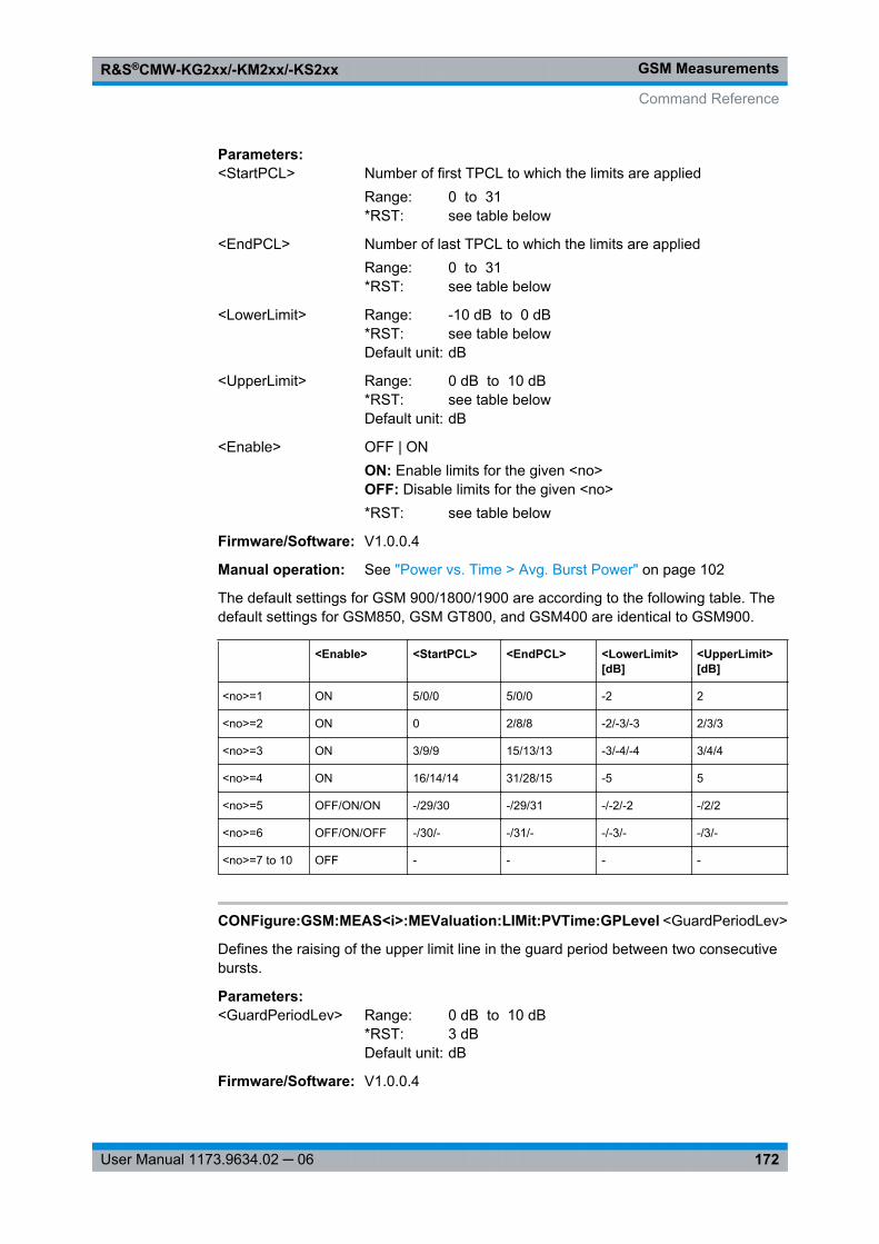
GSM MeasurementsR&S®CMW-KG2xx/-KM2xx/-KS2xx
172User Manual 1173.9634.02 ─ 06
Parameters:<StartPCL> Number of first TPCL to which the limits are applied
Range: 0 to 31*RST: see table below
<EndPCL> Number of last TPCL to which the limits are appliedRange: 0 to 31*RST: see table below
<LowerLimit> Range: -10 dB to 0 dB*RST: see table belowDefault unit: dB
<UpperLimit> Range: 0 dB to 10 dB*RST: see table belowDefault unit: dB
<Enable> OFF | ONON: Enable limits for the given <no>OFF: Disable limits for the given <no>*RST: see table below
Firmware/Software: V1.0.0.4
Manual operation: See "Power vs. Time > Avg. Burst Power" on page 102
The default settings for GSM 900/1800/1900 are according to the following table. Thedefault settings for GSM850, GSM GT800, and GSM400 are identical to GSM900.
<Enable> <StartPCL> <EndPCL> <LowerLimit>[dB]
<UpperLimit>[dB]
<no>=1 ON 5/0/0 5/0/0 -2 2
<no>=2 ON 0 2/8/8 -2/-3/-3 2/3/3
<no>=3 ON 3/9/9 15/13/13 -3/-4/-4 3/4/4
<no>=4 ON 16/14/14 31/28/15 -5 5
<no>=5 OFF/ON/ON -/29/30 -/29/31 -/-2/-2 -/2/2
<no>=6 OFF/ON/OFF -/30/- -/31/- -/-3/- -/3/-
<no>=7 to 10 OFF - - - -
CONFigure:GSM:MEAS<i>:MEValuation:LIMit:PVTime:GPLevel <GuardPeriodLev>
Defines the raising of the upper limit line in the guard period between two consecutivebursts.
Parameters:<GuardPeriodLev> Range: 0 dB to 10 dB
*RST: 3 dBDefault unit: dB
Firmware/Software: V1.0.0.4
Command Reference
GSM MeasurementsR&S®CMW-KG2xx/-KM2xx/-KS2xx
173User Manual 1173.9634.02 ─ 06
Manual operation: See "Power vs. Time > Avg. Burst Power" on page 102
CONFigure:GSM:MEAS<i>:MEValuation:LIMit:GMSK:PVTime:UPPer:REDGe<no>:STATic <TimeStart>, <TimeEnd>, <RelLevStart>, <RelLevEnd>,<AbsLevStart>, <AbsLevEnd>, <Enable>
CONFigure:GSM:MEAS<i>:MEValuation:LIMit:GMSK:PVTime:UPPer:UPARt<no>:STATic <TimeStart>, <TimeEnd>, <RelLevStart>, <RelLevEnd>, <AbsLevStart>,<AbsLevEnd>, <Enable>
CONFigure:GSM:MEAS<i>:MEValuation:LIMit:GMSK:PVTime:UPPer:FEDGe<no>:STATic <TimeStart>, <TimeEnd>, <RelLevStart>, <RelLevEnd>,<AbsLevStart>, <AbsLevEnd>, <Enable>
CONFigure:GSM:MEAS<i>:MEValuation:LIMit:EPSK:PVTime:UPPer:REDGe<no>:STATic <TimeStart>, <TimeEnd>, <RelLevStart>, <RelLevEnd>, <AbsLevStart>,<AbsLevEnd>, <Enable>
CONFigure:GSM:MEAS<i>:MEValuation:LIMit:EPSK:PVTime:UPPer:UPARt<no>:STATic <TimeStart>, <TimeEnd>, <RelLevStart>, <RelLevEnd>, <AbsLevStart>,<AbsLevEnd>, <Enable>
CONFigure:GSM:MEAS<i>:MEValuation:LIMit:EPSK:PVTime:UPPer:FEDGe<no>:STATic <TimeStart>, <TimeEnd>, <RelLevStart>, <RelLevEnd>, <AbsLevStart>,<AbsLevEnd>, <Enable>
CONFigure:GSM:MEAS<i>:MEValuation:LIMit:QAM<ModOrder>:PVTime:UPPer:REDGe<no>:STATic <TimeStart>, <TimeEnd>, <RelLevStart>, <RelLevEnd>,<AbsLevStart>, <AbsLevEnd>, <Enable>
CONFigure:GSM:MEAS<i>:MEValuation:LIMit:QAM<ModOrder>:PVTime:UPPer:UPARt<no>:STATic <TimeStart>, <TimeEnd>, <RelLevStart>, <RelLevEnd>,<AbsLevStart>, <AbsLevEnd>, <Enable>
CONFigure:GSM:MEAS<i>:MEValuation:LIMit:QAM<ModOrder>:PVTime:UPPer:FEDGe<no>:STATic <TimeStart>, <TimeEnd>, <RelLevStart>, <RelLevEnd>,<AbsLevStart>, <AbsLevEnd>, <Enable>
These commands define and activate upper limit lines for the measured power vs. time.The lines apply to the modulation schemes GMSK, 8PSK (EPSK) or 16-QAM (QAM16).Each line consists of three sections: rising edge (REDGe), useful part (UPARt) and fallingedge (FEDGe). Each section consists of several areas for which relative and absolutelimits can be defined (if both are defined the higher limit overrules the lower one).
Suffix: <ModOrder>
.16Modulation order, at present fixed
<no> 1..4 for rising/falling edge, 1..3 for useful partNumber of the area
Parameters:<TimeStart><TimeEnd>
Start and end time of the areaRange: -50 µs to 600 µs*RST: see tables belowDefault unit: s
Command Reference
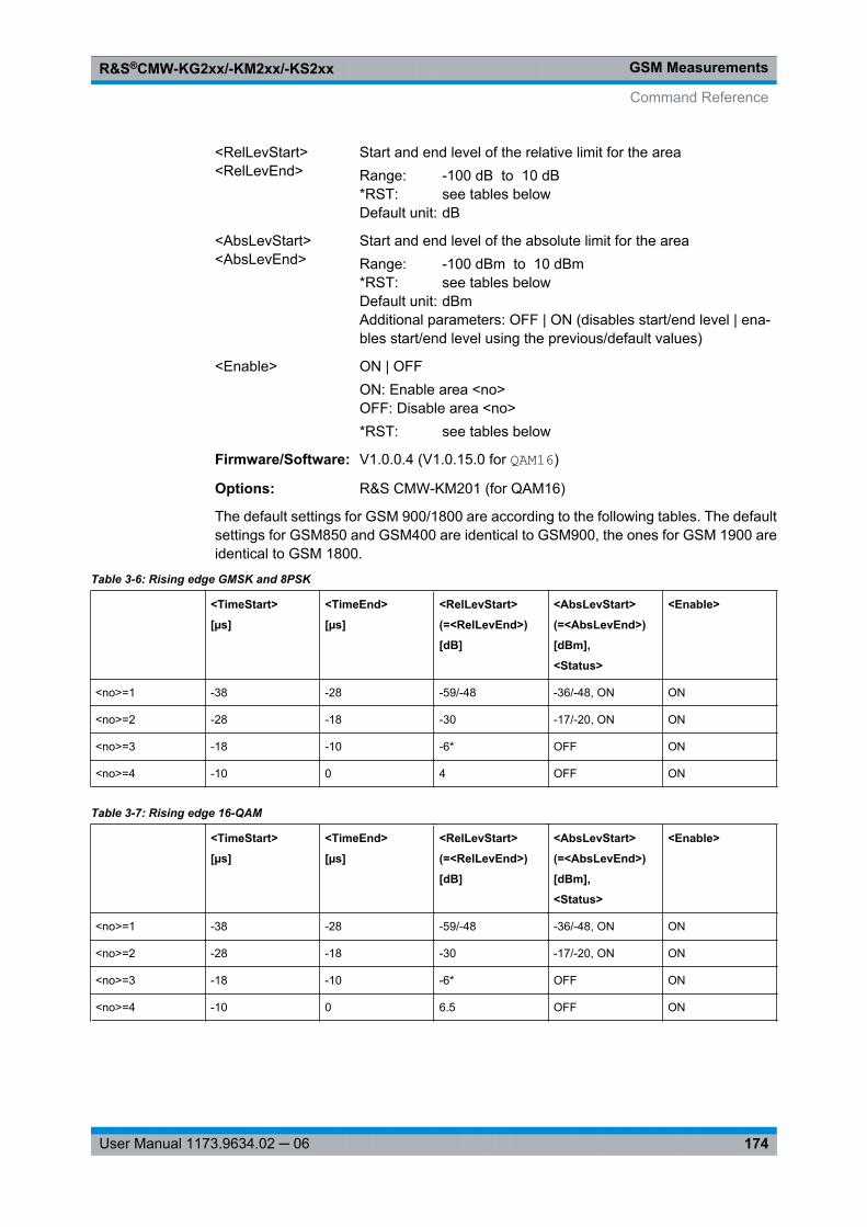
GSM MeasurementsR&S®CMW-KG2xx/-KM2xx/-KS2xx
174User Manual 1173.9634.02 ─ 06
<RelLevStart><RelLevEnd>
Start and end level of the relative limit for the areaRange: -100 dB to 10 dB*RST: see tables belowDefault unit: dB
<AbsLevStart><AbsLevEnd>
Start and end level of the absolute limit for the areaRange: -100 dBm to 10 dBm*RST: see tables belowDefault unit: dBmAdditional parameters: OFF | ON (disables start/end level | ena-bles start/end level using the previous/default values)
<Enable> ON | OFFON: Enable area <no>OFF: Disable area <no>*RST: see tables below
Firmware/Software: V1.0.0.4 (V1.0.15.0 for QAM16)
Options: R&S CMW-KM201 (for QAM16)
The default settings for GSM 900/1800 are according to the following tables. The defaultsettings for GSM850 and GSM400 are identical to GSM900, the ones for GSM 1900 areidentical to GSM 1800.
Table 3-6: Rising edge GMSK and 8PSK
<TimeStart>
[µs]
<TimeEnd>
[µs]
<RelLevStart>
(=<RelLevEnd>)
[dB]
<AbsLevStart>
(=<AbsLevEnd>)
[dBm],
<Status>
<Enable>
<no>=1 -38 -28 -59/-48 -36/-48, ON ON
<no>=2 -28 -18 -30 -17/-20, ON ON
<no>=3 -18 -10 -6* OFF ON
<no>=4 -10 0 4 OFF ON
Table 3-7: Rising edge 16-QAM
<TimeStart>
[µs]
<TimeEnd>
[µs]
<RelLevStart>
(=<RelLevEnd>)
[dB]
<AbsLevStart>
(=<AbsLevEnd>)
[dBm],
<Status>
<Enable>
<no>=1 -38 -28 -59/-48 -36/-48, ON ON
<no>=2 -28 -18 -30 -17/-20, ON ON
<no>=3 -18 -10 -6* OFF ON
<no>=4 -10 0 6.5 OFF ON
Command Reference
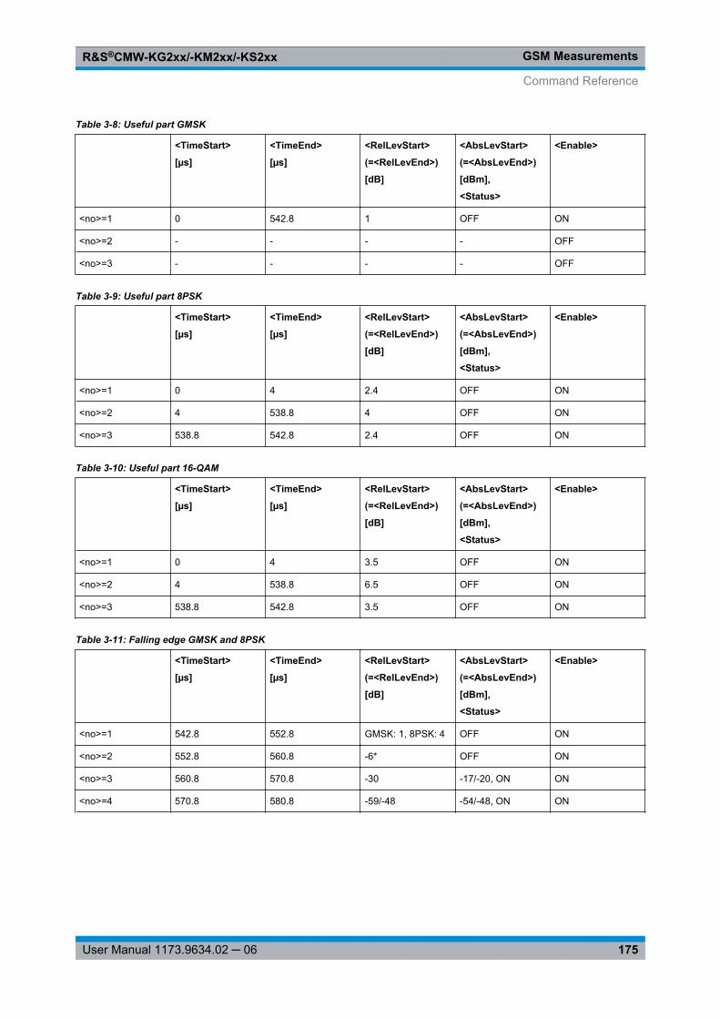
GSM MeasurementsR&S®CMW-KG2xx/-KM2xx/-KS2xx
175User Manual 1173.9634.02 ─ 06
Table 3-8: Useful part GMSK
<TimeStart>
[µs]
<TimeEnd>
[µs]
<RelLevStart>
(=<RelLevEnd>)
[dB]
<AbsLevStart>
(=<AbsLevEnd>)
[dBm],
<Status>
<Enable>
<no>=1 0 542.8 1 OFF ON
<no>=2 - - - - OFF
<no>=3 - - - - OFF
Table 3-9: Useful part 8PSK
<TimeStart>
[µs]
<TimeEnd>
[µs]
<RelLevStart>
(=<RelLevEnd>)
[dB]
<AbsLevStart>
(=<AbsLevEnd>)
[dBm],
<Status>
<Enable>
<no>=1 0 4 2.4 OFF ON
<no>=2 4 538.8 4 OFF ON
<no>=3 538.8 542.8 2.4 OFF ON
Table 3-10: Useful part 16-QAM
<TimeStart>
[µs]
<TimeEnd>
[µs]
<RelLevStart>
(=<RelLevEnd>)
[dB]
<AbsLevStart>
(=<AbsLevEnd>)
[dBm],
<Status>
<Enable>
<no>=1 0 4 3.5 OFF ON
<no>=2 4 538.8 6.5 OFF ON
<no>=3 538.8 542.8 3.5 OFF ON
Table 3-11: Falling edge GMSK and 8PSK
<TimeStart>
[µs]
<TimeEnd>
[µs]
<RelLevStart>
(=<RelLevEnd>)
[dB]
<AbsLevStart>
(=<AbsLevEnd>)
[dBm],
<Status>
<Enable>
<no>=1 542.8 552.8 GMSK: 1, 8PSK: 4 OFF ON
<no>=2 552.8 560.8 -6* OFF ON
<no>=3 560.8 570.8 -30 -17/-20, ON ON
<no>=4 570.8 580.8 -59/-48 -54/-48, ON ON
Command Reference
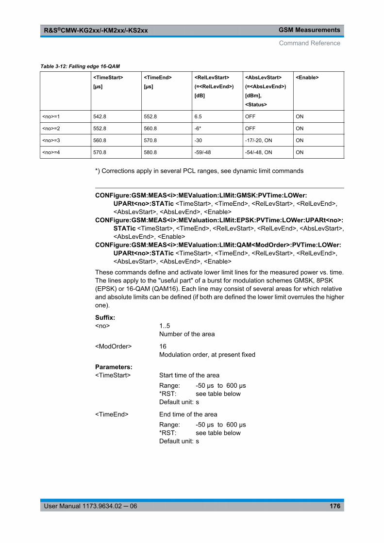
GSM MeasurementsR&S®CMW-KG2xx/-KM2xx/-KS2xx
176User Manual 1173.9634.02 ─ 06
Table 3-12: Falling edge 16-QAM
<TimeStart>
[µs]
<TimeEnd>
[µs]
<RelLevStart>
(=<RelLevEnd>)
[dB]
<AbsLevStart>
(=<AbsLevEnd>)
[dBm],
<Status>
<Enable>
<no>=1 542.8 552.8 6.5 OFF ON
<no>=2 552.8 560.8 -6* OFF ON
<no>=3 560.8 570.8 -30 -17/-20, ON ON
<no>=4 570.8 580.8 -59/-48 -54/-48, ON ON
*) Corrections apply in several PCL ranges, see dynamic limit commands
CONFigure:GSM:MEAS<i>:MEValuation:LIMit:GMSK:PVTime:LOWer:UPARt<no>:STATic <TimeStart>, <TimeEnd>, <RelLevStart>, <RelLevEnd>,<AbsLevStart>, <AbsLevEnd>, <Enable>
CONFigure:GSM:MEAS<i>:MEValuation:LIMit:EPSK:PVTime:LOWer:UPARt<no>:STATic <TimeStart>, <TimeEnd>, <RelLevStart>, <RelLevEnd>, <AbsLevStart>,<AbsLevEnd>, <Enable>
CONFigure:GSM:MEAS<i>:MEValuation:LIMit:QAM<ModOrder>:PVTime:LOWer:UPARt<no>:STATic <TimeStart>, <TimeEnd>, <RelLevStart>, <RelLevEnd>,<AbsLevStart>, <AbsLevEnd>, <Enable>
These commands define and activate lower limit lines for the measured power vs. time.The lines apply to the "useful part" of a burst for modulation schemes GMSK, 8PSK(EPSK) or 16-QAM (QAM16). Each line may consist of several areas for which relativeand absolute limits can be defined (if both are defined the lower limit overrules the higherone).
Suffix: <no>
.1..5Number of the area
<ModOrder> 16Modulation order, at present fixed
Parameters:<TimeStart> Start time of the area
Range: -50 µs to 600 µs*RST: see table belowDefault unit: s
<TimeEnd> End time of the areaRange: -50 µs to 600 µs*RST: see table belowDefault unit: s
Command Reference
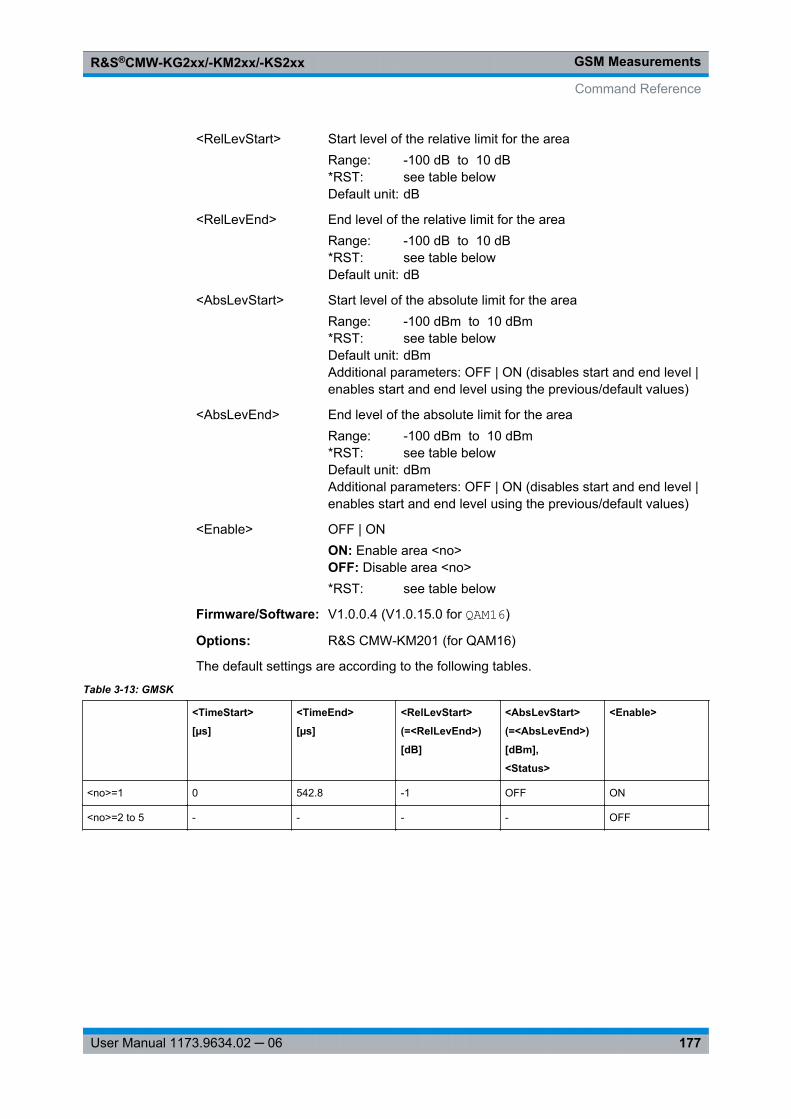
GSM MeasurementsR&S®CMW-KG2xx/-KM2xx/-KS2xx
177User Manual 1173.9634.02 ─ 06
<RelLevStart> Start level of the relative limit for the areaRange: -100 dB to 10 dB*RST: see table belowDefault unit: dB
<RelLevEnd> End level of the relative limit for the areaRange: -100 dB to 10 dB*RST: see table belowDefault unit: dB
<AbsLevStart> Start level of the absolute limit for the areaRange: -100 dBm to 10 dBm*RST: see table belowDefault unit: dBmAdditional parameters: OFF | ON (disables start and end level |enables start and end level using the previous/default values)
<AbsLevEnd> End level of the absolute limit for the areaRange: -100 dBm to 10 dBm*RST: see table belowDefault unit: dBmAdditional parameters: OFF | ON (disables start and end level |enables start and end level using the previous/default values)
<Enable> OFF | ONON: Enable area <no>OFF: Disable area <no>*RST: see table below
Firmware/Software: V1.0.0.4 (V1.0.15.0 for QAM16)
Options: R&S CMW-KM201 (for QAM16)
The default settings are according to the following tables.
Table 3-13: GMSK
<TimeStart>
[µs]
<TimeEnd>
[µs]
<RelLevStart>
(=<RelLevEnd>)
[dB]
<AbsLevStart>
(=<AbsLevEnd>)
[dBm],
<Status>
<Enable>
<no>=1 0 542.8 -1 OFF ON
<no>=2 to 5 - - - - OFF
Command Reference
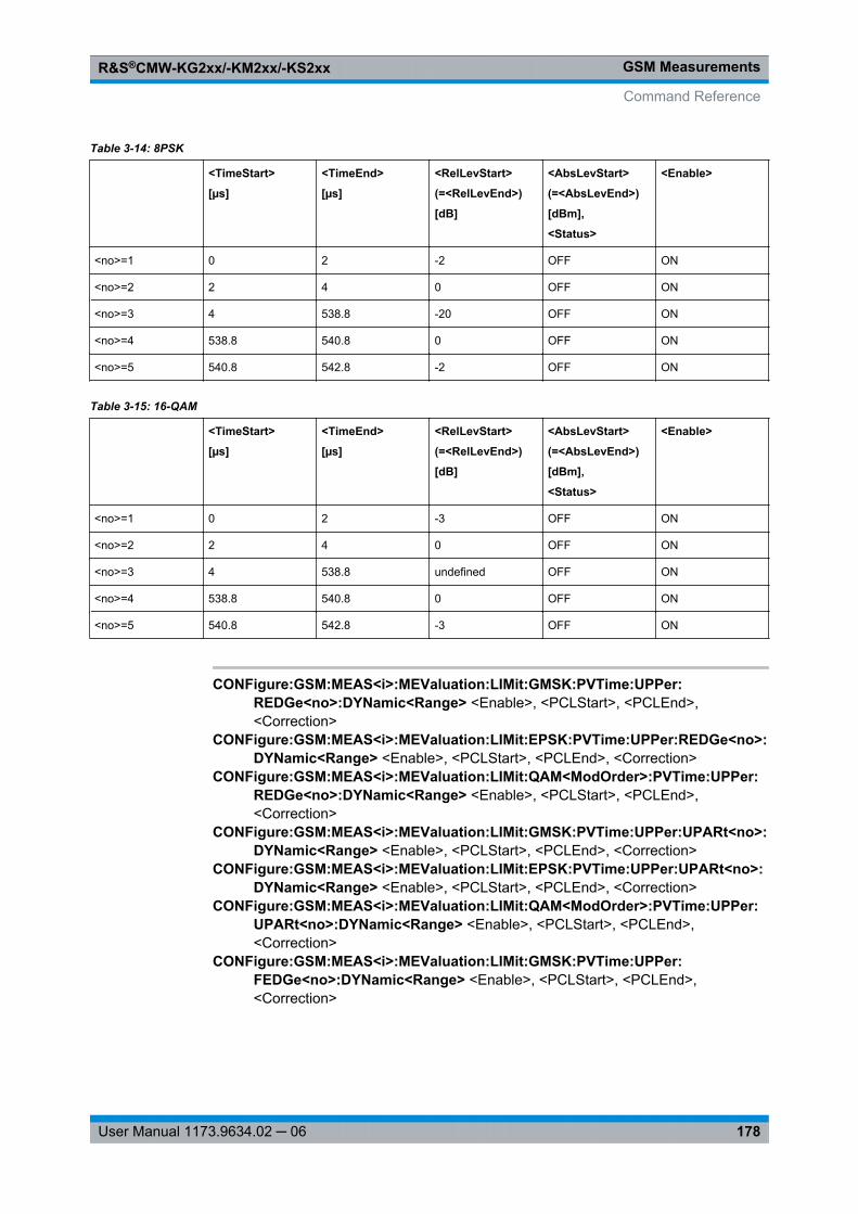
GSM MeasurementsR&S®CMW-KG2xx/-KM2xx/-KS2xx
178User Manual 1173.9634.02 ─ 06
Table 3-14: 8PSK
<TimeStart>
[µs]
<TimeEnd>
[µs]
<RelLevStart>
(=<RelLevEnd>)
[dB]
<AbsLevStart>
(=<AbsLevEnd>)
[dBm],
<Status>
<Enable>
<no>=1 0 2 -2 OFF ON
<no>=2 2 4 0 OFF ON
<no>=3 4 538.8 -20 OFF ON
<no>=4 538.8 540.8 0 OFF ON
<no>=5 540.8 542.8 -2 OFF ON
Table 3-15: 16-QAM
<TimeStart>
[µs]
<TimeEnd>
[µs]
<RelLevStart>
(=<RelLevEnd>)
[dB]
<AbsLevStart>
(=<AbsLevEnd>)
[dBm],
<Status>
<Enable>
<no>=1 0 2 -3 OFF ON
<no>=2 2 4 0 OFF ON
<no>=3 4 538.8 undefined OFF ON
<no>=4 538.8 540.8 0 OFF ON
<no>=5 540.8 542.8 -3 OFF ON
CONFigure:GSM:MEAS<i>:MEValuation:LIMit:GMSK:PVTime:UPPer:REDGe<no>:DYNamic<Range> <Enable>, <PCLStart>, <PCLEnd>,<Correction>
CONFigure:GSM:MEAS<i>:MEValuation:LIMit:EPSK:PVTime:UPPer:REDGe<no>:DYNamic<Range> <Enable>, <PCLStart>, <PCLEnd>, <Correction>
CONFigure:GSM:MEAS<i>:MEValuation:LIMit:QAM<ModOrder>:PVTime:UPPer:REDGe<no>:DYNamic<Range> <Enable>, <PCLStart>, <PCLEnd>,<Correction>
CONFigure:GSM:MEAS<i>:MEValuation:LIMit:GMSK:PVTime:UPPer:UPARt<no>:DYNamic<Range> <Enable>, <PCLStart>, <PCLEnd>, <Correction>
CONFigure:GSM:MEAS<i>:MEValuation:LIMit:EPSK:PVTime:UPPer:UPARt<no>:DYNamic<Range> <Enable>, <PCLStart>, <PCLEnd>, <Correction>
CONFigure:GSM:MEAS<i>:MEValuation:LIMit:QAM<ModOrder>:PVTime:UPPer:UPARt<no>:DYNamic<Range> <Enable>, <PCLStart>, <PCLEnd>,<Correction>
CONFigure:GSM:MEAS<i>:MEValuation:LIMit:GMSK:PVTime:UPPer:FEDGe<no>:DYNamic<Range> <Enable>, <PCLStart>, <PCLEnd>,<Correction>
Command Reference
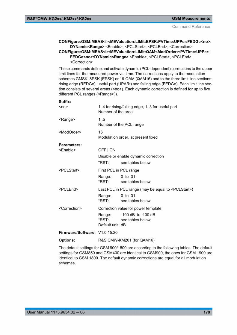
GSM MeasurementsR&S®CMW-KG2xx/-KM2xx/-KS2xx
179User Manual 1173.9634.02 ─ 06
CONFigure:GSM:MEAS<i>:MEValuation:LIMit:EPSK:PVTime:UPPer:FEDGe<no>:DYNamic<Range> <Enable>, <PCLStart>, <PCLEnd>, <Correction>
CONFigure:GSM:MEAS<i>:MEValuation:LIMit:QAM<ModOrder>:PVTime:UPPer:FEDGe<no>:DYNamic<Range> <Enable>, <PCLStart>, <PCLEnd>,<Correction>
These commands define and activate dynamic (PCL-dependent) corrections to the upperlimit lines for the measured power vs. time. The corrections apply to the modulationschemes GMSK, 8PSK (EPSK) or 16-QAM (QAM16) and to the three limit line sections:rising edge (REDGe), useful part (UPARt) and falling edge (FEDGe). Each limit line sec-tion consists of several areas (<no>). Each dynamic correction is defined for up to fivedifferent PCL ranges (<Range>)).
Suffix: <no>
.1..4 for rising/falling edge, 1..3 for useful partNumber of the area
<Range> 1..5Number of the PCL range
<ModOrder> 16Modulation order, at present fixed
Parameters:<Enable> OFF | ON
Disable or enable dynamic correction*RST: see tables below
<PCLStart> First PCL in PCL rangeRange: 0 to 31*RST: see tables below
<PCLEnd> Last PCL in PCL range (may be equal to <PCLStart>)Range: 0 to 31*RST: see tables below
<Correction> Correction value for power templateRange: -100 dB to 100 dB*RST: see tables belowDefault unit: dB
Firmware/Software: V1.0.15.20
Options: R&S CMW-KM201 (for QAM16)
The default settings for GSM 900/1800 are according to the following tables. The defaultsettings for GSM850 and GSM400 are identical to GSM900, the ones for GSM 1900 areidentical to GSM 1800. The default dynamic corrections are equal for all modulationschemes.
Command Reference
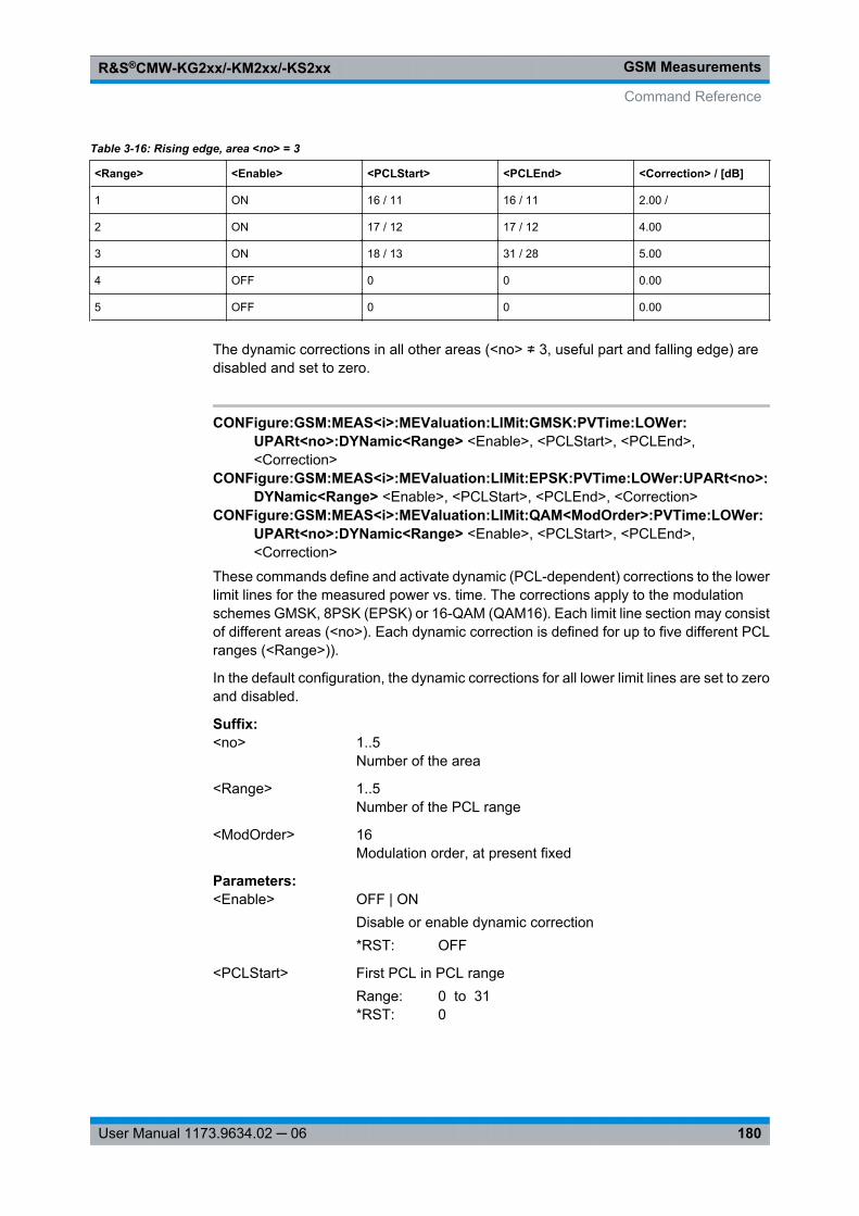
GSM MeasurementsR&S®CMW-KG2xx/-KM2xx/-KS2xx
180User Manual 1173.9634.02 ─ 06
Table 3-16: Rising edge, area <no> = 3
<Range> <Enable> <PCLStart> <PCLEnd> <Correction> / [dB]
1 ON 16 / 11 16 / 11 2.00 /
2 ON 17 / 12 17 / 12 4.00
3 ON 18 / 13 31 / 28 5.00
4 OFF 0 0 0.00
5 OFF 0 0 0.00
The dynamic corrections in all other areas (<no> ≠ 3, useful part and falling edge) aredisabled and set to zero.
CONFigure:GSM:MEAS<i>:MEValuation:LIMit:GMSK:PVTime:LOWer:UPARt<no>:DYNamic<Range> <Enable>, <PCLStart>, <PCLEnd>,<Correction>
CONFigure:GSM:MEAS<i>:MEValuation:LIMit:EPSK:PVTime:LOWer:UPARt<no>:DYNamic<Range> <Enable>, <PCLStart>, <PCLEnd>, <Correction>
CONFigure:GSM:MEAS<i>:MEValuation:LIMit:QAM<ModOrder>:PVTime:LOWer:UPARt<no>:DYNamic<Range> <Enable>, <PCLStart>, <PCLEnd>,<Correction>
These commands define and activate dynamic (PCL-dependent) corrections to the lowerlimit lines for the measured power vs. time. The corrections apply to the modulationschemes GMSK, 8PSK (EPSK) or 16-QAM (QAM16). Each limit line section may consistof different areas (<no>). Each dynamic correction is defined for up to five different PCLranges (<Range>)).
In the default configuration, the dynamic corrections for all lower limit lines are set to zeroand disabled.
Suffix: <no>
.1..5Number of the area
<Range> 1..5Number of the PCL range
<ModOrder> 16Modulation order, at present fixed
Parameters:<Enable> OFF | ON
Disable or enable dynamic correction*RST: OFF
<PCLStart> First PCL in PCL rangeRange: 0 to 31*RST: 0
Command Reference
GSM MeasurementsR&S®CMW-KG2xx/-KM2xx/-KS2xx
181User Manual 1173.9634.02 ─ 06
<PCLEnd> Last PCL in PCL range (may be equal to <PCLStart>)Range: 0 to 31*RST: 0
<Correction> Correction value for power templateRange: -100 dB to 100 dB*RST: 0 dBDefault unit: dB
Firmware/Software: V1.0.15.20
Options: R&S CMW-KM201 (for QAM16)
3.6.3.17 Limits (Spectrum Modulation)
The following commands define limit lines for spectrum due to modulation measure-ments.
CONFigure: GSM:MEAS<i>:MEValuation: LIMit:GMSK:SMODulation: RPOWer.....................181CONFigure: GSM:MEAS<i>:MEValuation: LIMit:GMSK:SMODulation: MPOint<no> ................182CONFigure: GSM:MEAS<i>:MEValuation: LIMit:EPSK:SMODulation: RPOWer......................183CONFigure: GSM:MEAS<i>:MEValuation: LIMit:QAM<ModOrder>: SMODulation: RPOWer.....183CONFigure: GSM:MEAS<i>:MEValuation: LIMit:EPSK:SMODulation: MPOint<no> .................183CONFigure: GSM:MEAS<i>:MEValuation: LIMit:QAM<ModOrder>: SMODulation:
MPOint<no> ........................................................................................................183
CONFigure:GSM:MEAS<i>:MEValuation:LIMit:GMSK:SMODulation:RPOWer<Minimum>, <Maximum>
Defines two reference power values for the modulation scheme GMSK. These values arerelevant in the context of CONFigure: GSM: MEAS<i>: MEValuation: LIMit: GMSK: SMODulation: MPOint<no> .
Parameters:<Minimum> Low reference power value
Range: 0 dBm to 43 dBm*RST: 33 dBmDefault unit: dBm
<Maximum> High reference power valueRange: 0 dBm to 43 dBm*RST: 39 dBmDefault unit: dBm
Firmware/Software: V1.0.0.4
Manual operation: See "Spectrum Modulation and Spectrum Switching"on page 103
Command Reference
GSM MeasurementsR&S®CMW-KG2xx/-KM2xx/-KS2xx
182User Manual 1173.9634.02 ─ 06
CONFigure:GSM:MEAS<i>:MEValuation:LIMit:GMSK:SMODulation:MPOint<no><MinPowLevelRel>, <MaxPowLevelRel>, <AbsPowerLevel>, <Enable>
Defines and activates a limit line for the modulation scheme GMSK for a certain frequencyoffset. The specified limits apply above the high power reference value and below thelow power reference value defined by CONFigure: GSM: MEAS<i>: MEValuation: LIMit: GMSK: SMODulation: RPOWer . Between the two reference power values thelimits are determined by linear interpolation.
Suffix: <no>
.1..20Number of the frequency offset value.The offsets are defined by the command CONFigure: GSM: MEAS<i>: MEValuation: SMODulation: OFRequence .
Parameters:<MinPowLevelRel> Relative power limit applicable below the low reference power
Range: -120 dB to 31.5 dB*RST: <no> = 1 to 3 [dB]: 0.5, -30, -33 / <no> = 4 to 20: -60
dBDefault unit: dB
<MaxPowLevelRel> Relative power limit applicable above the high reference powerRange: -120 dB to 31.5 dB*RST: <no> = 1 to 4 [dB]: 0.5, -30, -33, -60 / <no> = 5 to 20:
-66 dBDefault unit: dB
<AbsPowerLevel> Alternative absolute power limit. If the relative limits are tighterthan the absolute limit, the latter applies.Range: -120 dBm to 31.5 dBm*RST: <no> = 1 to 4: -36 dBm / <no> = 5 to 20: -51 dBmDefault unit: dBm
<Enable> OFF | ONON: Enable limits for the given <no>OFF: Disable limits for the given <no>*RST: <no> = 1 to 11: ON / <no> = 12 to 20: OFF
Firmware/Software: V1.0.0.4
Manual operation: See "Spectrum Modulation and Spectrum Switching"on page 103
Command Reference
GSM MeasurementsR&S®CMW-KG2xx/-KM2xx/-KS2xx
183User Manual 1173.9634.02 ─ 06
CONFigure:GSM:MEAS<i>:MEValuation:LIMit:EPSK:SMODulation:RPOWer<Minimum>, <Maximum>
CONFigure:GSM:MEAS<i>:MEValuation:LIMit:QAM<ModOrder>:SMODulation:RPOWer <Minimum>, <Maximum>
Define two reference power values for the modulation schemes 8PSK and 16-QAM.These values are relevant in the context of CONFigure: GSM: MEAS<i>: MEValuation: LIMit: EPSK: SMODulation: MPOint<no> and CONFigure: GSM: MEAS<i>: MEValuation: LIMit: QAM<ModOrder>: SMODulation: MPOint<no> .
Suffix: <ModOrder>
.16Modulation order, at present fixed
Parameters:<Minimum> Low reference power value
Range: 0 dBm to 43 dBm*RST: 33 dBmDefault unit: dBm
<Maximum> High reference power valueRange: 0 dBm to 43 dBm*RST: 34 dBmDefault unit: dBm
Firmware/Software: V1.0.0.4 (V1.0.15.0 for QAM16)
Options: R&S CMW-KM201 (for QAM16)
CONFigure:GSM:MEAS<i>:MEValuation:LIMit:EPSK:SMODulation:MPOint<no><MinPowLevelRel>, <MaxPowLevelRel>, <AbsPowerLevel>, <Enable>
CONFigure:GSM:MEAS<i>:MEValuation:LIMit:QAM<ModOrder>:SMODulation:MPOint<no> <MinPowLevelRel>, <MaxPowLevelRel>, <AbsPowerLevel>,<Enable>
Defines and activates a limit line for the modulation schemes 8PSK and 16-QAM and fora certain frequency offset. The specified limits apply above the high power referencevalue and below the low power reference value defined by CONFigure: GSM: MEAS<i>: MEValuation: LIMit: EPSK: SMODulation: RPOWer and CONFigure: GSM: MEAS<i>: MEValuation: LIMit: QAM<ModOrder>: SMODulation: RPOWer .Between the two reference power values the limits are determined by linear interpolation.
Suffix: <no>
.1..20Number of the frequency offset value.The offsets are defined by the command CONFigure: GSM: MEAS<i>: MEValuation: SMODulation: OFRequence .
<ModOrder> 16Modulation order, at present fixed
Command Reference
GSM MeasurementsR&S®CMW-KG2xx/-KM2xx/-KS2xx
184User Manual 1173.9634.02 ─ 06
Parameters:<MinPowLevelRel> Relative power limit applicable below the low reference power
Range: -120 dB to 31.5 dB*RST: <no> = 1 to 4 [dB]: 0.5, -30, -33, -54 / <no> = 5 to 20:
-60 dBDefault unit: dB
<MaxPowLevelRel> Relative power limit applicable above the high reference powerRange: -120 dB to 31.5 dB*RST: <no> = 1 to 4 [dB]: 0.5, -30, -33, -54 / <no> = 5 to 20:
-66 dBDefault unit: dB
<AbsPowerLevel> Alternative absolute power limit. If the relative limits are tighterthan the absolute limit, the latter applies.Range: -120 dBm to 31.5 dBm*RST: <no> = 1 to 4: -36 dBm / <no> = 5 to 20: -51 dBmDefault unit: dBm
<Enable> ON | OFFON: Enable limits for the given <no>OFF: Disable limits for the given <no>*RST: <no> = 1 to 11: ON / <no> = 12 to 20: OFF
Firmware/Software: V1.0.0.4 (V1.0.15.0 for QAM16)
Options: R&S CMW-KM201 (for QAM16)
3.6.3.18 Limits (Spectrum Switching)
The following commands define limit lines for spectrum due to switching measurements.
CONFigure: GSM:MEAS<i>:MEValuation: LIMit:GMSK:SSWitching: PLEVel ..........................184CONFigure: GSM:MEAS<i>:MEValuation: LIMit:GMSK:SSWitching: MPOint<no> ...................185CONFigure: GSM:MEAS<i>:MEValuation: LIMit:EPSK:SSWitching: PLEVel ...........................186CONFigure: GSM:MEAS<i>:MEValuation: LIMit:QAM<ModOrder>: SSWitching: PLEVel ..........186CONFigure: GSM:MEAS<i>:MEValuation: LIMit:EPSK:SSWitching: MPOint<no> ....................187CONFigure: GSM:MEAS<i>:MEValuation: LIMit:QAM<ModOrder>: SSWitching:
MPOint<no> ........................................................................................................187
CONFigure:GSM:MEAS<i>:MEValuation:LIMit:GMSK:SSWitching:PLEVel<Enable1>, ..., <Enable10>, <PowerLevel1>, ..., <PowerLevel10>
Defines and activates reference power values for the modulation scheme GMSK. Thesevalues are relevant in the context of CONFigure: GSM: MEAS<i>: MEValuation: LIMit: GMSK: SSWitching: MPOint<no> .
Command Reference
GSM MeasurementsR&S®CMW-KG2xx/-KM2xx/-KS2xx
185User Manual 1173.9634.02 ─ 06
Parameters:<Enable1> ...<Enable10>
ON | OFFON: Enable reference valueOFF: Disable reference value*RST: ON
<PowerLevel1> ...<PowerLevel10>
Reference power valueRange: 0 dBm to 39 dBm*RST: Level 1 to 10 [dBm]: 39, 37, 35, 33, 31, 29, 27, 25,
23, 21Default unit: dBm
Firmware/Software: V1.0.0.4
Manual operation: See "Spectrum Modulation and Spectrum Switching"on page 103
CONFigure:GSM:MEAS<i>:MEValuation:LIMit:GMSK:SSWitching:MPOint<no><PowerLimit1>, ..., <PowerLimit10>, <Enable>
Defines and activates a limit line for the modulation scheme GMSK for a certain frequencyoffset. The specified limits apply at the reference power values defined by CONFigure: GSM: MEAS<i>: MEValuation: LIMit: GMSK: SSWitching: PLEVel .Between the reference power values the limits are determined by linear interpolation.
Suffix: <no>
.1..20Number of the frequency offset value. The offsets are defined bythe command CONFigure: GSM: MEAS<i>: MEValuation: SSWitching: OFRequence
Parameters:<PowerLimit1> ...<PowerLimit10>
Relative power limit applicable at the corresponding referencepowerRange: -60 dB to 30 dB*RST: see table belowDefault unit: dB
<Enable> ON | OFFON: Enable limits for the given <no>OFF: Disable limits for the given <no>*RST: see table below
Firmware/Software: V1.0.0.4
Manual operation: See "Spectrum Modulation and Spectrum Switching"on page 103
The default settings for GSM 900/1800/1900 are according to the following tables. Thedefault settings for GSM850, GSM GT800, and GSM400 are identical to GSM900.
Command Reference
GSM MeasurementsR&S®CMW-KG2xx/-KM2xx/-KS2xx
186User Manual 1173.9634.02 ─ 06
Table 3-17: Default values GSM 900 for <Enable> (ON/OFF) and <PowerLimit> (values in dB) dependingon <no>
<no> Enable Limit1 Limit2 Limit3 Limit4 Limit5 Limit6 Limit7 Limit8 Limit9 Limit10
1 ON -13 -15 -17 -19 -21 -23 -23 -23 -23 -23
2 ON -21 -21 -21 -21 -23 -25 -26 -26 -26 -26
3 ON -21 -21 -21 -21 -23 -25 -27 -29 -31 -32
4 ON -24 -24 -24 -24 -26 -28 -30 -32 -34 -36
5 to 20 OFF 0 0 0 0 0 0 0 0 0 0
Table 3-18: Default values GSM 1800 for <Enable> (ON/OFF) and <PowerLimit> (values in dB) dependingon <no>
<no> Enable Limit1 Limit2 Limit3 Limit4 Limit5 Limit6 Limit7 Limit8 Limit9 Limit10
1 ON -16 -18 -20 -22 -23 -23 -23 -23 -23 OFF, 0
2 ON -21 -21 -22 -24 -25 -26 -26 -26 -26 OFF, 0
3 ON -21 -21 -22 -24 -26 -28 -30 -31 -32 OFF, 0
4 ON -24 -24 -25 -27 -29 -31 -33 -35 -36 OFF, 0
5 to 20 OFF 0 0 0 0 0 0 0 0 0 0
Table 3-19: Default values GSM 1900 for <Enable> (ON/OFF) and <PowerLimit> (values in dB) dependingon <no>
<no> Enable Limit1 Limit2 Limit3 Limit4 Limit5 Limit6 Limit7 Limit8 Limit9/10
1 ON -19 -20 -22 -23 -23 -23 -23 -23 OFF, 0
2 ON -22 -22 -24 -25 -26 -26 -26 -26 OFF, 0
3 ON -22 -22 -24 -26 -28 -30 -31 -32 OFF, 0
4 ON -25 -25 -27 -29 -31 -33 -35 -36 OFF, 0
5 to 20 OFF 0 0 0 0 0 0 0 0 0
CONFigure:GSM:MEAS<i>:MEValuation:LIMit:EPSK:SSWitching:PLEVel<Enable1>, ..., <Enable10>, <PowerLevel1>, ..., <PowerLevel10>
CONFigure:GSM:MEAS<i>:MEValuation:LIMit:QAM<ModOrder>:SSWitching:PLEVel <Enable1>, ..., <Enable10>, <PowerLevel1>, ..., <PowerLevel10>
Define and activate reference power values for the modulation schemes 8PSK and 16-QAM. These values are relevant in the context of CONFigure: GSM: MEAS<i>: MEValuation: LIMit: GMSK: SSWitching: MPOint<no> and CONFigure: GSM: MEAS<i>: MEValuation: LIMit: QAM<ModOrder>: SSWitching: MPOint<no> .
Suffix: <ModOrder>
.16Modulation order, at present fixed
Command Reference
GSM MeasurementsR&S®CMW-KG2xx/-KM2xx/-KS2xx
187User Manual 1173.9634.02 ─ 06
Parameters:<Enable1> ...<Enable10>
OFF | ONON: Enable reference valueOFF: Disable reference value*RST: ON
<PowerLevel1> ...<PowerLevel10>
Reference power valueRange: 0 dBm to 39 dBm*RST: Level 1 to 10 [dBm]: 39, 37, 35, 33, 31, 29, 27, 25,
23, 21Default unit: dBm
Firmware/Software: V1.0.0.4 (V1.0.15.0 for QAM16)
Options: R&S CMW-KM201 (for QAM16)
CONFigure:GSM:MEAS<i>:MEValuation:LIMit:EPSK:SSWitching:MPOint<no><PowerLimit1>, ..., <PowerLimit10>, <Enable>
CONFigure:GSM:MEAS<i>:MEValuation:LIMit:QAM<ModOrder>:SSWitching:MPOint<no> <PowerLimit1>, ..., <PowerLimit10>, <Enable>
Define and activate a limit line for the modulation schemes 8PSK and 16-QAM for acertain frequency offset. The specified limits apply at the reference power values definedby CONFigure: GSM: MEAS<i>: MEValuation: LIMit: EPSK: SSWitching: PLEVel and CONFigure: GSM: MEAS<i>: MEValuation: LIMit: QAM<ModOrder>: SSWitching: PLEVel . Between the reference power values the limits are determinedby linear interpolation.
Suffix: <no>
.1..20Number of the frequency offset value.The offsets are defined by the command CONFigure: GSM: MEAS<i>: MEValuation: SSWitching: OFRequence
<ModOrder> 16Modulation order, at present fixed
Parameters:<PowerLimit1> ...<PowerLimit10>
Relative power limit applicable at the corresponding referencepowerRange: -60 dB to 30 dB*RST: see table belowDefault unit: dB
<Enable> OFF | ONON: Enable limits for the given <no>OFF: Disable limits for the given <no>*RST: see table below
Firmware/Software: V1.0.0.4 (V1.0.15.0 for QAM16)
Options: R&S CMW-KM201 (for QAM16)
Command Reference
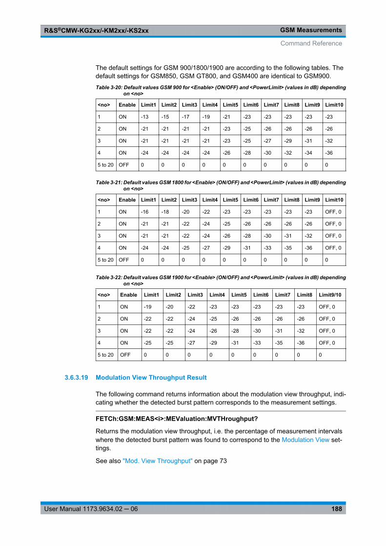
GSM MeasurementsR&S®CMW-KG2xx/-KM2xx/-KS2xx
188User Manual 1173.9634.02 ─ 06
The default settings for GSM 900/1800/1900 are according to the following tables. Thedefault settings for GSM850, GSM GT800, and GSM400 are identical to GSM900.
Table 3-20: Default values GSM 900 for <Enable> (ON/OFF) and <PowerLimit> (values in dB) dependingon <no>
<no> Enable Limit1 Limit2 Limit3 Limit4 Limit5 Limit6 Limit7 Limit8 Limit9 Limit10
1 ON -13 -15 -17 -19 -21 -23 -23 -23 -23 -23
2 ON -21 -21 -21 -21 -23 -25 -26 -26 -26 -26
3 ON -21 -21 -21 -21 -23 -25 -27 -29 -31 -32
4 ON -24 -24 -24 -24 -26 -28 -30 -32 -34 -36
5 to 20 OFF 0 0 0 0 0 0 0 0 0 0
Table 3-21: Default values GSM 1800 for <Enable> (ON/OFF) and <PowerLimit> (values in dB) dependingon <no>
<no> Enable Limit1 Limit2 Limit3 Limit4 Limit5 Limit6 Limit7 Limit8 Limit9 Limit10
1 ON -16 -18 -20 -22 -23 -23 -23 -23 -23 OFF, 0
2 ON -21 -21 -22 -24 -25 -26 -26 -26 -26 OFF, 0
3 ON -21 -21 -22 -24 -26 -28 -30 -31 -32 OFF, 0
4 ON -24 -24 -25 -27 -29 -31 -33 -35 -36 OFF, 0
5 to 20 OFF 0 0 0 0 0 0 0 0 0 0
Table 3-22: Default values GSM 1900 for <Enable> (ON/OFF) and <PowerLimit> (values in dB) dependingon <no>
<no> Enable Limit1 Limit2 Limit3 Limit4 Limit5 Limit6 Limit7 Limit8 Limit9/10
1 ON -19 -20 -22 -23 -23 -23 -23 -23 OFF, 0
2 ON -22 -22 -24 -25 -26 -26 -26 -26 OFF, 0
3 ON -22 -22 -24 -26 -28 -30 -31 -32 OFF, 0
4 ON -25 -25 -27 -29 -31 -33 -35 -36 OFF, 0
5 to 20 OFF 0 0 0 0 0 0 0 0 0
3.6.3.19 Modulation View Throughput Result
The following command returns information about the modulation view throughput, indi-cating whether the detected burst pattern corresponds to the measurement settings.
FETCh:GSM:MEAS<i>:MEValuation:MVTHroughput?
Returns the modulation view throughput, i.e. the percentage of measurement intervalswhere the detected burst pattern was found to correspond to the Modulation View set-tings.
See also "Mod. View Throughput" on page 73
Command Reference
GSM MeasurementsR&S®CMW-KG2xx/-KM2xx/-KS2xx
189User Manual 1173.9634.02 ─ 06
Return values: <Reliability> Reliability Indicator
<MVThroughput> Modulation view throughputRange: 0 % to 100 %Default unit: %
Example: See Performing Single-Shot Measurements
Usage: Query only
Firmware/Software: V3.0.20
3.6.3.20 EVM Results (Traces)
The following commands return the EVM trace results of the multi evaluation measure-ment for the "measured slot" ( CONFigure: GSM: MEAS<i>: MEValuation: MSLots ).
FETCh:GSM:MEAS<i>:MEValuation:TRACe:EVMagnitude:CURRent?FETCh:GSM:MEAS<i>:MEValuation:TRACe:EVMagnitude:AVERage?FETCh:GSM:MEAS<i>:MEValuation:TRACe:EVMagnitude:MAXimum?READ:GSM:MEAS<i>:MEValuation:TRACe:EVMagnitude:CURRent?READ:GSM:MEAS<i>:MEValuation:TRACe:EVMagnitude:AVERage?READ:GSM:MEAS<i>:MEValuation:TRACe:EVMagnitude:MAXimum?Returns the values of the EVM traces. The results of the current, average and maximumtraces can be retrieved.
Return values: <Reliability> Reliability Indicator
<Result_1> ...<Result_n>
n EVM results, depending on the burst and modulation type8PSK/16-QAM modulation: 142 values (one value per symbolperiod, symbol 3 to symbol 144)GMSK modulation: 588 values (four values per symbol period,symbol 0.5 to symbol 147.5)Access burst: 348 values (four values per symbol period, symbol0.5 to symbol 87.5)Range: 0 % to 100 %Default unit: %
Usage: Query only
Firmware/Software: V1.0.0.4
For additional information concerning syntax elements and returned values refer to Con-ventions and General Information.
3.6.3.21 Magnitude Error Results (Traces)
The following commands return the magnitude error trace results of the multi evaluationmeasurement for the "measured slot" ( CONFigure: GSM: MEAS<i>: MEValuation: MSLots ).
Command Reference
GSM MeasurementsR&S®CMW-KG2xx/-KM2xx/-KS2xx
190User Manual 1173.9634.02 ─ 06
FETCh:GSM:MEAS<i>:MEValuation:TRACe:MERRor:CURRent?FETCh:GSM:MEAS<i>:MEValuation:TRACe:MERRor:AVERage?FETCh:GSM:MEAS<i>:MEValuation:TRACe:MERRor:MAXimum?READ:GSM:MEAS<i>:MEValuation:TRACe:MERRor:CURRent?READ:GSM:MEAS<i>:MEValuation:TRACe:MERRor:AVERage?READ:GSM:MEAS<i>:MEValuation:TRACe:MERRor:MAXimum?Returns the values of the magnitude error traces. The results of the current, average andminimum/maximum traces can be retrieved.
Return values: <Reliability> Reliability Indicator
<Result_1> ...<Result_n>
n magnitude error results, depending on the type of modulation8PSK/16-QAM modulation: 142 values (one value per symbolperiod, symbol 3 to symbol 144)GMSK modulation: 588 values (four values per symbol period,symbol 0.5 to symbol 147.5)Access burst: 348 values (four values per symbol period, symbol0.5 to symbol 87.5)Range: -100 % to 100 %Default unit: %
Usage: Query only
Firmware/Software: V1.0.0.4
For additional information concerning syntax elements and returned values refer to Con-ventions and General Information.
3.6.3.22 Phase Error Results (Traces)
The following commands return the phase error trace results of the multi evaluation mea-surement for the "measured slot" ( CONFigure: GSM: MEAS<i>: MEValuation: MSLots ).
FETCh:GSM:MEAS<i>:MEValuation:TRACe:PERRor:CURRent?FETCh:GSM:MEAS<i>:MEValuation:TRACe:PERRor:AVERage?FETCh:GSM:MEAS<i>:MEValuation:TRACe:PERRor:MAXimum?READ:GSM:MEAS<i>:MEValuation:TRACe:PERRor:CURRent?READ:GSM:MEAS<i>:MEValuation:TRACe:PERRor:AVERage?READ:GSM:MEAS<i>:MEValuation:TRACe:PERRor:MAXimum?Returns the values of the phase error traces. The results of the current, average andminimum/maximum traces can be retrieved.
Return values: <Reliability> Reliability Indicator
Command Reference
GSM MeasurementsR&S®CMW-KG2xx/-KM2xx/-KS2xx
191User Manual 1173.9634.02 ─ 06
<Result_1> ...<Result_n>
n phase error results, depending on the type of modulation8PSK/16-QAM modulation: 142 values (one value per symbolperiod, symbol 3 to symbol 144)GMSK modulation: 588 values (four values per symbol period,symbol 0.5 to symbol 147.5)Access burst: 348 values (four values per symbol period, symbol0.5 to symbol 87.5)Range: -180 deg to 180 degDefault unit: deg
Usage: Query only
Firmware/Software: V1.0.0.4
For additional information concerning syntax elements and returned values refer to Con-ventions and General Information.
3.6.3.23 Modulation Results (Single Values)
The following commands return results of the multi evaluation measurement, measuredin the "Measured Slot" ( CONFigure: GSM: MEAS<i>: MEValuation: MSLots ).
FETCh:GSM:MEAS<i>:MEValuation: MODulation: CURRent? .............................................191FETCh:GSM:MEAS<i>:MEValuation: MODulation: MAXimum? ............................................191READ: GSM:MEAS<i>:MEValuation: MODulation: CURRent? ...............................................191READ: GSM:MEAS<i>:MEValuation: MODulation: MAXimum? .............................................191CALCulate: GSM:MEAS<i>:MEValuation: MODulation: CURRent? ........................................191CALCulate: GSM:MEAS<i>:MEValuation: MODulation: MAXimum? .......................................191FETCh:GSM:MEAS<i>:MEValuation: MODulation: AVERage? .............................................193READ: GSM:MEAS<i>:MEValuation: MODulation: AVERage? ..............................................193CALCulate: GSM:MEAS<i>:MEValuation: MODulation: AVERage? ........................................193READ: GSM:MEAS<i>:MEValuation: MODulation: SDEViation? ............................................194FETCh:GSM:MEAS<i>:MEValuation: MODulation: SDEViation? ...........................................194FETCh:GSM:MEAS<i>:MEValuation: MODulation: PERCentile? ..........................................195READ: GSM:MEAS<i>:MEValuation: MODulation: PERCentile? ............................................195CALCulate: GSM:MEAS<i>:MEValuation: MODulation: PERCentile? .....................................195FETCh:GSM:MEAS<i>:MEValuation: MODulation: DBITs?..................................................196
FETCh:GSM:MEAS<i>:MEValuation:MODulation:CURRent?FETCh:GSM:MEAS<i>:MEValuation:MODulation:MAXimum?READ:GSM:MEAS<i>:MEValuation:MODulation:CURRent?READ:GSM:MEAS<i>:MEValuation:MODulation:MAXimum?CALCulate:GSM:MEAS<i>:MEValuation:MODulation:CURRent?CALCulate:GSM:MEAS<i>:MEValuation:MODulation:MAXimum?Returns the current and minimum/maximum single slot modulation results of the multievaluation measurement.
The values described below are returned by FETCh and READ commands. CALCulatecommands return limit check results instead, one value for each result listed below.
Command Reference
GSM MeasurementsR&S®CMW-KG2xx/-KM2xx/-KS2xx
192User Manual 1173.9634.02 ─ 06
The number to the left of each result parameter is provided for easy identification of theparameter position within the result array.
Return values: <1_Reliability> Reliability Indicator
<2_OutOfTolerance> Percentage of measurement intervals / bursts of the statistic count( CONFigure: GSM: MEAS<i>: MEValuation: SCOunt: MODulation ) exceeding the specified modulation limits.
Range: 0 % to 100 %Default unit: %
<3_EVMRMS><4_EVMpeak>
Error vector magnitude RMS and peak valueRange: 0 % to 100 %Default unit: %
<5_MagErrorRMS> Magnitude error RMS valueRange: 0 % to 100 %Default unit: %
<6_MagErrorPeak> Magnitude error peak valueRange: -100 % to 100 %Default unit: %
<7_PhaseErrorRMS> Phase error RMS valueRange: 0 deg to 180 degDefault unit: deg
<8_PhaseErrorPeak> Phase error peak valueRange: -180 deg to 180 degDefault unit: deg
<9_IQoffset> I/Q origin offsetRange: -100 dB to 0 dBDefault unit: dB
<10_IQimbalance> I/Q imbalanceRange: -100 dB to 0 dBDefault unit: dB
<11_FrequencyError> Carrier frequency errorRange: -56000 Hz to 56000 HzDefault unit: Hz
<12_TimingError> Transmit time errorRange: -100 Sym to 100 SymDefault unit: Sym
<13_BurstPower> Burst PowerRange: -100 dBm to 55 dBmDefault unit: dBm
Command Reference
GSM MeasurementsR&S®CMW-KG2xx/-KM2xx/-KS2xx
193User Manual 1173.9634.02 ─ 06
<14_AMPMdelay> AM-PM delay (determined for 8PSK and 16-QAM modulation only- for GMSK zeros are returned)Range: -0.9225E-6 s to 0.9225E-6 sDefault unit: s
Example: See Single-Shot and Continuous Measurements
Usage: Query only
Firmware/Software: V1.0.0.4
For additional information concerning syntax elements and returned values refer to Con-ventions and General Information.
FETCh:GSM:MEAS<i>:MEValuation:MODulation:AVERage?READ:GSM:MEAS<i>:MEValuation:MODulation:AVERage?CALCulate:GSM:MEAS<i>:MEValuation:MODulation:AVERage?Returns the average single slot modulation results of the multi evaluation measurement.
The values described below are returned by FETCh and READ commands. CALCulatecommands return limit check results instead, one value for each result listed below.
The number to the left of each result parameter is provided for easy identification of theparameter position within the result array.
Return values: <1_Reliability> Reliability Indicator
<2_OutOfTolerance> Percentage of measurement intervals / bursts of the statistic count( CONFigure: GSM: MEAS<i>: MEValuation: SCOunt: MODulation ) exceeding the specified modulation limits.
Range: 0 % to 100 %Default unit: %
<3_EVMRMS><4_EVMpeak>
Error vector magnitude RMS and peak valueRange: 0 % to 100 %Default unit: %
<5_MagErrorRMS><6_MagErrorPeak>
Magnitude error RMS and peak valueRange: 0 % to 100 %Default unit: %
<7_PhaseErrorRMS><8_PhaseErrorPeak>
Phase error RMS and peak valueRange: 0 deg to 180 degDefault unit: deg
<9_IQoffset> I/Q origin offsetRange: -100 dB to 0 dBDefault unit: dB
<10_IQimbalance> I/Q imbalanceRange: -100 dB to 0 dBDefault unit: dB
Command Reference
GSM MeasurementsR&S®CMW-KG2xx/-KM2xx/-KS2xx
194User Manual 1173.9634.02 ─ 06
<11_FrequencyError> Carrier frequency errorRange: -56000 Hz to 56000 HzDefault unit: Hz
<12_TimingError> Transmit time errorRange: -100 Sym to 100 SymDefault unit: Sym
<13_BurstPower> Burst PowerRange: -100 dBm to 55 dBmDefault unit: dBm
<14_AMPMdelay> AMPM delay (determined for 8PSK and 16-QAM modulation only- for GMSK zeros are returned)Range: -0.9225E-6 s to 0.9225E-6 sDefault unit: s
Usage: Query only
Firmware/Software: V1.0.0.4
For additional information concerning syntax elements and returned values refer to Con-ventions and General Information.
READ:GSM:MEAS<i>:MEValuation:MODulation:SDEViation?FETCh:GSM:MEAS<i>:MEValuation:MODulation:SDEViation?Returns the standard deviation of the single slot modulation results of the multi evaluationmeasurement.
The number to the left of each result parameter is provided for easy identification of theparameter position within the result array.
Return values: <1_Reliability> Reliability Indicator
<2_OutOfTolerance> Percentage of measurement intervals / bursts of the statistic count( CONFigure: GSM: MEAS<i>: MEValuation: SCOunt: SMODulation ) exceeding the specified modulation limits.
Range: 0 % to 100 %Default unit: %
<3_EVMRMS><4_EVMpeak>
Error vector magnitude RMS and peak valueRange: 0 % to 50 %Default unit: %
<5_MagErrorRMS><6_MagErrorPeak>
Magnitude error RMS and peak valueRange: 0 % to 50 %Default unit: %
<7_PhaseErrorRMS><8_PhaseErrorPeak>
Phase error RMS and peak valueRange: 0 deg to 90 degDefault unit: deg
Command Reference
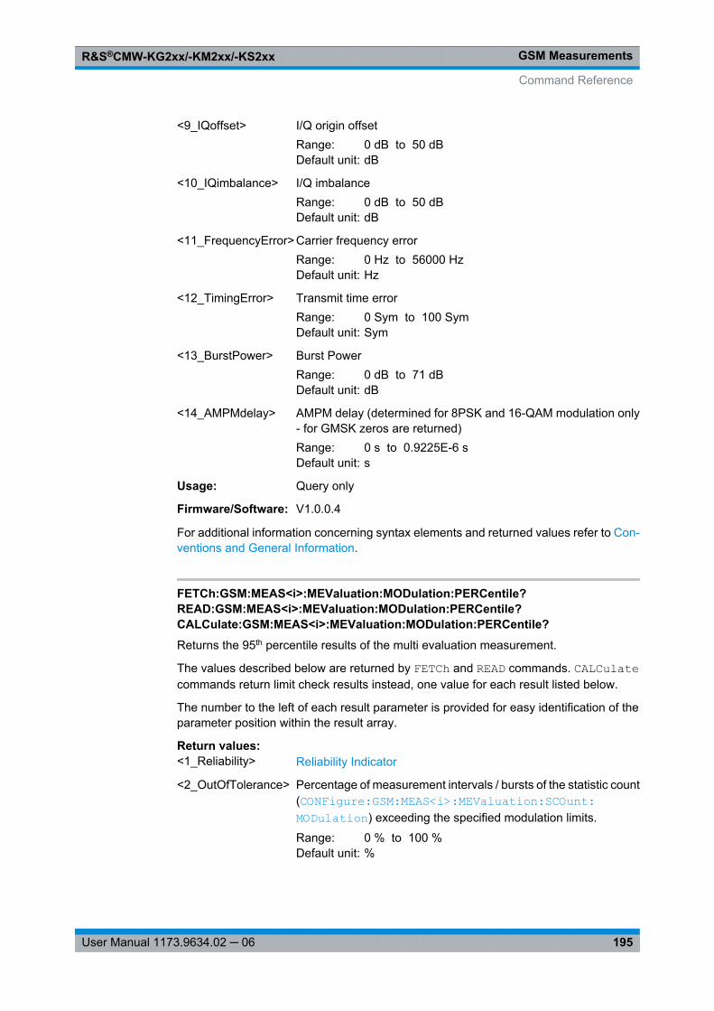
GSM MeasurementsR&S®CMW-KG2xx/-KM2xx/-KS2xx
195User Manual 1173.9634.02 ─ 06
<9_IQoffset> I/Q origin offsetRange: 0 dB to 50 dBDefault unit: dB
<10_IQimbalance> I/Q imbalanceRange: 0 dB to 50 dBDefault unit: dB
<11_FrequencyError> Carrier frequency errorRange: 0 Hz to 56000 HzDefault unit: Hz
<12_TimingError> Transmit time errorRange: 0 Sym to 100 SymDefault unit: Sym
<13_BurstPower> Burst PowerRange: 0 dB to 71 dBDefault unit: dB
<14_AMPMdelay> AMPM delay (determined for 8PSK and 16-QAM modulation only- for GMSK zeros are returned)Range: 0 s to 0.9225E-6 sDefault unit: s
Usage: Query only
Firmware/Software: V1.0.0.4
For additional information concerning syntax elements and returned values refer to Con-ventions and General Information.
FETCh:GSM:MEAS<i>:MEValuation:MODulation:PERCentile?READ:GSM:MEAS<i>:MEValuation:MODulation:PERCentile?CALCulate:GSM:MEAS<i>:MEValuation:MODulation:PERCentile?Returns the 95th percentile results of the multi evaluation measurement.
The values described below are returned by FETCh and READ commands. CALCulatecommands return limit check results instead, one value for each result listed below.
The number to the left of each result parameter is provided for easy identification of theparameter position within the result array.
Return values: <1_Reliability> Reliability Indicator
<2_OutOfTolerance> Percentage of measurement intervals / bursts of the statistic count( CONFigure: GSM: MEAS<i>: MEValuation: SCOunt: MODulation ) exceeding the specified modulation limits.
Range: 0 % to 100 %Default unit: %
Command Reference
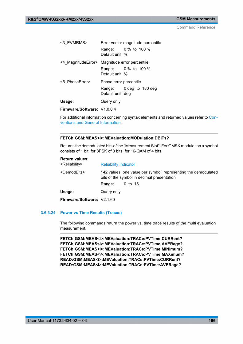
GSM MeasurementsR&S®CMW-KG2xx/-KM2xx/-KS2xx
196User Manual 1173.9634.02 ─ 06
<3_EVMRMS> Error vector magnitude percentileRange: 0 % to 100 %Default unit: %
<4_MagnitudeError> Magnitude error percentileRange: 0 % to 100 %Default unit: %
<5_PhaseError> Phase error percentileRange: 0 deg to 180 degDefault unit: deg
Usage: Query only
Firmware/Software: V1.0.0.4
For additional information concerning syntax elements and returned values refer to Con-ventions and General Information.
FETCh:GSM:MEAS<i>:MEValuation:MODulation:DBITs?
Returns the demodulated bits of the "Measurement Slot". For GMSK modulation a symbolconsists of 1 bit, for 8PSK of 3 bits, for 16-QAM of 4 bits.
Return values: <Reliability> Reliability Indicator
<DemodBits> 142 values, one value per symbol, representing the demodulatedbits of the symbol in decimal presentationRange: 0 to 15
Usage: Query only
Firmware/Software: V2.1.60
3.6.3.24 Power vs Time Results (Traces)
The following commands return the power vs. time trace results of the multi evaluationmeasurement.
FETCh:GSM:MEAS<i>:MEValuation:TRACe:PVTime:CURRent?FETCh:GSM:MEAS<i>:MEValuation:TRACe:PVTime:AVERage?FETCh:GSM:MEAS<i>:MEValuation:TRACe:PVTime:MINimum?FETCh:GSM:MEAS<i>:MEValuation:TRACe:PVTime:MAXimum?READ:GSM:MEAS<i>:MEValuation:TRACe:PVTime:CURRent?READ:GSM:MEAS<i>:MEValuation:TRACe:PVTime:AVERage?
Command Reference
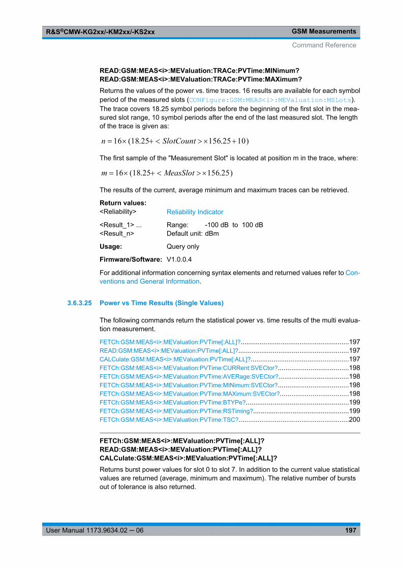
GSM MeasurementsR&S®CMW-KG2xx/-KM2xx/-KS2xx
197User Manual 1173.9634.02 ─ 06
READ:GSM:MEAS<i>:MEValuation:TRACe:PVTime:MINimum?READ:GSM:MEAS<i>:MEValuation:TRACe:PVTime:MAXimum?Returns the values of the power vs. time traces. 16 results are available for each symbolperiod of the measured slots ( CONFigure: GSM: MEAS<i>: MEValuation: MSLots ).The trace covers 18.25 symbol periods before the beginning of the first slot in the mea-sured slot range, 10 symbol periods after the end of the last measured slot. The lengthof the trace is given as:
)1025.15625.18(16 SlotCountn
The first sample of the "Measurement Slot" is located at position m in the trace, where:
)25.15625.18(16 MeasSlotm
The results of the current, average minimum and maximum traces can be retrieved.
Return values: <Reliability> Reliability Indicator
<Result_1> ...<Result_n>
Range: -100 dB to 100 dBDefault unit: dBm
Usage: Query only
Firmware/Software: V1.0.0.4
For additional information concerning syntax elements and returned values refer to Con-ventions and General Information.
3.6.3.25 Power vs Time Results (Single Values)
The following commands return the statistical power vs. time results of the multi evalua-tion measurement.
FETCh:GSM:MEAS<i>:MEValuation: PVTime[:ALL]? .........................................................197READ: GSM:MEAS<i>:MEValuation: PVTime[:ALL]? ..........................................................197CALCulate: GSM:MEAS<i>:MEValuation: PVTime[:ALL]? ....................................................197FETCh:GSM:MEAS<i>:MEValuation: PVTime:CURRent: SVECtor? .....................................198FETCh:GSM:MEAS<i>:MEValuation: PVTime:AVERage: SVECtor? .....................................198FETCh:GSM:MEAS<i>:MEValuation: PVTime:MINimum: SVECtor? .....................................198FETCh:GSM:MEAS<i>:MEValuation: PVTime:MAXimum: SVECtor? ....................................198FETCh:GSM:MEAS<i>:MEValuation: PVTime:BTYPe? ......................................................199FETCh:GSM:MEAS<i>:MEValuation: PVTime:RSTiming? ...................................................199FETCh:GSM:MEAS<i>:MEValuation: PVTime:TSC? ..........................................................200
FETCh:GSM:MEAS<i>:MEValuation:PVTime[:ALL]?READ:GSM:MEAS<i>:MEValuation:PVTime[:ALL]?CALCulate:GSM:MEAS<i>:MEValuation:PVTime[:ALL]?Returns burst power values for slot 0 to slot 7. In addition to the current value statisticalvalues are returned (average, minimum and maximum). The relative number of burstsout of tolerance is also returned.
Command Reference
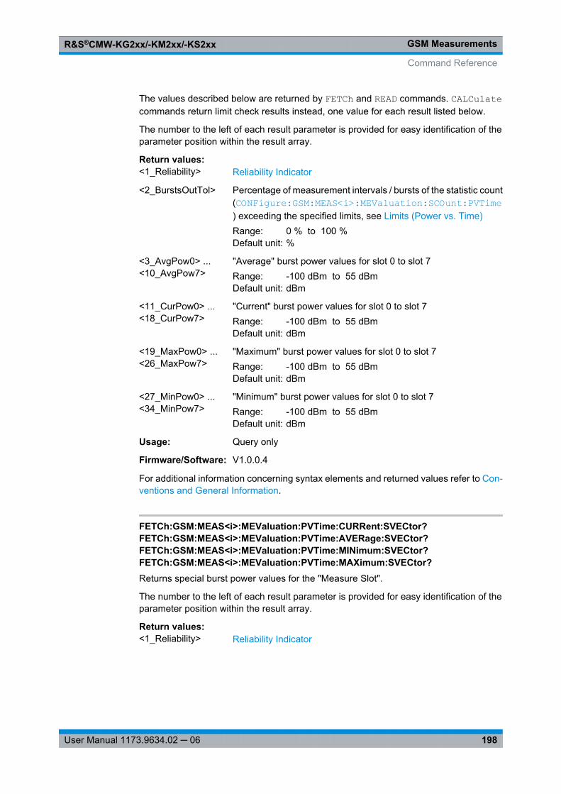
GSM MeasurementsR&S®CMW-KG2xx/-KM2xx/-KS2xx
198User Manual 1173.9634.02 ─ 06
The values described below are returned by FETCh and READ commands. CALCulatecommands return limit check results instead, one value for each result listed below.
The number to the left of each result parameter is provided for easy identification of theparameter position within the result array.
Return values: <1_Reliability> Reliability Indicator
<2_BurstsOutTol> Percentage of measurement intervals / bursts of the statistic count( CONFigure: GSM: MEAS<i>: MEValuation: SCOunt: PVTime ) exceeding the specified limits, see Limits (Power vs. Time)Range: 0 % to 100 %Default unit: %
<3_AvgPow0> ...<10_AvgPow7>
"Average" burst power values for slot 0 to slot 7Range: -100 dBm to 55 dBmDefault unit: dBm
<11_CurPow0> ...<18_CurPow7>
"Current" burst power values for slot 0 to slot 7Range: -100 dBm to 55 dBmDefault unit: dBm
<19_MaxPow0> ...<26_MaxPow7>
"Maximum" burst power values for slot 0 to slot 7Range: -100 dBm to 55 dBmDefault unit: dBm
<27_MinPow0> ...<34_MinPow7>
"Minimum" burst power values for slot 0 to slot 7Range: -100 dBm to 55 dBmDefault unit: dBm
Usage: Query only
Firmware/Software: V1.0.0.4
For additional information concerning syntax elements and returned values refer to Con-ventions and General Information.
FETCh:GSM:MEAS<i>:MEValuation:PVTime:CURRent:SVECtor?FETCh:GSM:MEAS<i>:MEValuation:PVTime:AVERage:SVECtor?FETCh:GSM:MEAS<i>:MEValuation:PVTime:MINimum:SVECtor?FETCh:GSM:MEAS<i>:MEValuation:PVTime:MAXimum:SVECtor?Returns special burst power values for the "Measure Slot".
The number to the left of each result parameter is provided for easy identification of theparameter position within the result array.
Return values: <1_Reliability> Reliability Indicator
Command Reference
GSM MeasurementsR&S®CMW-KG2xx/-KM2xx/-KS2xx
199User Manual 1173.9634.02 ─ 06
<2_UsefulPartMin><3_UsefulPartMax>
Minimum and maximum power across the useful part of the "Mea-sure Slot".Range: -100 dB to 100 dBDefault unit: dB
<4_Subvector1> ...<15_Subvector12>
Burst power at [μs]: –28 , –18, –10, 0, 2, 4, 538.2, 540.2, 542.8,552.8, 560.8, 570.8Range: -100 dB to 100 dBDefault unit: dB
Usage: Query only
Firmware/Software: V1.0.10.1
For additional information concerning syntax elements and returned values refer to Con-ventions and General Information.
FETCh:GSM:MEAS<i>:MEValuation:PVTime:BTYPe?
Returns the detected burst type for all measured timeslots. 8 values are returned, irre-spective of the "No. of Slots" measured ( CONFigure: GSM: MEAS<i>: MEValuation: MSLots ). If "No. of Slots" < 8, some of the returned values are NAN.
Return values: <Reliability> Reliability Indicator
<BurstType> OFF | GMSK | EPSK | ACCess | Q16Detected burst type (8 values):GMSK: Normal burst, GMSK-modulatedEPSK: Normal burst, 8PSK-modulatedACCess: Access burstQ16: Normal burst, 16-QAM-modulatedOFF: Inactive slot
Example: See Performing Single-Shot Measurements
Usage: Query only
Firmware/Software: V2.0.10
Options: R&S CMW-KM201 (for 16-QAM)
FETCh:GSM:MEAS<i>:MEValuation:PVTime:RSTiming?
Returns the slot timing for all measured timeslots, relative to the timing of the "Measure-ment Slot". The relative slot timing of the "Measurement Slot" is always zero. The relativeslot timing of the other timeslots is the deviation of the measured relative timing from thenominal timing, which is based on a timeslot length of 156.25 symbol durations.
The command returns 8 values, irrespective of the "No. of Slots" measured ( CONFigure: GSM: MEAS<i>: MEValuation: MSLots ). If "No. of Slots" < 8, some of thereturned values are NAN.
Command Reference
GSM MeasurementsR&S®CMW-KG2xx/-KM2xx/-KS2xx
200User Manual 1173.9634.02 ─ 06
Return values: <Reliability> Reliability Indicator
<RelSlotTiming> Range: -100 Sym to 100 SymDefault unit: symbols
Example: See Performing Single-Shot Measurements
Usage: Query only
Firmware/Software: V2.0.10
FETCh:GSM:MEAS<i>:MEValuation:PVTime:TSC?
Returns the detected Training Sequence Code (TSC) and burst type for all measuredtimeslots. 8 values are returned, irrespective of the "No. of Slots" measured ( CONFigure: GSM: MEAS<i>: MEValuation: MSLots ). If "No. of Slots" < 8, some of thereturned values are NAN.
Return values: <Reliability> Reliability Indicator
<TSC> OFF | NB0 | NB1 | NB2 | NB3 | NB4 | NB5 | NB6 | NB7 | DUMMy |AB0 | AB1 | AB2Detected TSC (8 values):OFF: Inactive slotNB0 ... NB7: Normal burst, training sequence TSC0 to TSC7DUMMY: Dummy burstAB0 ... AB2: Access burst, TSC 0 to TSC2
Example: See Performing Single-Shot Measurements
Usage: Query only
Firmware/Software: V2.0.10
3.6.3.26 Spectrum Modulation Results
The following commands return the spectrum modulation results of the multi evaluationmeasurement.
FETCh:GSM:MEAS<i>:MEValuation: SMODulation: FREQuency? .......................................201READ: GSM:MEAS<i>:MEValuation: SMODulation: FREQuency? .........................................201CALCulate: GSM:MEAS<i>:MEValuation: SMODulation: FREQuency? ..................................201FETCh:GSM:MEAS<i>:MEValuation: TRACe: SMODulation: TIME[:CURRent]? .....................201READ: GSM:MEAS<i>:MEValuation: TRACe: SMODulation: TIME[:CURRent]? ......................201READ: GSM:MEAS<i>:MEValuation: SMODulation? ...........................................................202FETCh:GSM:MEAS<i>:MEValuation: SMODulation? ..........................................................202
Command Reference
GSM MeasurementsR&S®CMW-KG2xx/-KM2xx/-KS2xx
201User Manual 1173.9634.02 ─ 06
FETCh:GSM:MEAS<i>:MEValuation:SMODulation:FREQuency?READ:GSM:MEAS<i>:MEValuation:SMODulation:FREQuency?CALCulate:GSM:MEAS<i>:MEValuation:SMODulation:FREQuency?Returns the average burst power measured at a series of frequencies. The frequenciesare determined by the offset values defined via the command CONFigure: GSM: MEAS<i>: MEValuation: SMODulation: OFRequence . All defined offset values areconsidered (irrespective of their activation status).
The values described below are returned by FETCh and READ commands. CALCulatecommands return limit check results instead, one value for each result listed below.
The number to the left of each result parameter is provided for easy identification of theparameter position within the result array.
Return values: <1_Reliability> Reliability Indicator
<2_PowOffsetM19>...<21_PowOffsetM0><22_PowCarrier><23_PowOffsetP0> ...<42_PowOffsetP19>
<PowOffsetM/P n> refers to the average burst power at the carrierfrequency minus/plus the frequency offset value number n.Range: -100 dB to 100 dBDefault unit: dB
Example: See Configuring a Spectrum Measurement
Usage: Query only
Firmware/Software: V1.0.0.4
For additional information concerning syntax elements and returned values refer to Con-ventions and General Information.
FETCh:GSM:MEAS<i>:MEValuation:TRACe:SMODulation:TIME[:CURRent]?READ:GSM:MEAS<i>:MEValuation:TRACe:SMODulation:TIME[:CURRent]?Returns the spectrum due to modulation trace values measured at a selected offset fre-quency ( CONFigure: GSM: MEAS<i>: MEValuation: SMODulation: TDFSelect ).
Return values: <Reliability> Reliability Indicator
<Result_1> ...<Result_n>
n power results, 4 for each symbol period of the "Measured Slot"Range: -100 dB to 100 dBDefault unit: dB
Example: See Configuring a Spectrum Measurement
Usage: Query only
Firmware/Software: V1.0.0.4
For additional information concerning syntax elements and returned values refer to Con-ventions and General Information.
Command Reference
GSM MeasurementsR&S®CMW-KG2xx/-KM2xx/-KS2xx
202User Manual 1173.9634.02 ─ 06
READ:GSM:MEAS<i>:MEValuation:SMODulation?FETCh:GSM:MEAS<i>:MEValuation:SMODulation?Returns general spectrum modulation results.
Return values: <Reliability> Reliability Indicator
<OutOfTolCount> Percentage of measurement intervals / bursts of the statistic count( CONFigure: GSM: MEAS<i>: MEValuation: SCOunt: SMODulation ) exceeding the specified limits (see Limits (Spec-trum Modulation)).Range: 0 % to 100 %Default unit: %
<CarrierPower> Measured carrier output power (reference power)Range: -100 dBm to 55 dBmDefault unit: dBm
Usage: Query only
Firmware/Software: V1.0.0.4
Manual operation: See "Statistical Overviews" on page 109
For additional information concerning syntax elements and returned values refer to Con-ventions and General Information.
3.6.3.27 Spectrum Switching Results
The following commands return the spectrum switching results of the multi evaluationmeasurement.
FETCh:GSM:MEAS<i>:MEValuation: SSWitching: FREQuency? ..........................................202READ: GSM:MEAS<i>:MEValuation: SSWitching: FREQuency? ...........................................202CALCulate: GSM:MEAS<i>:MEValuation: SSWitching: FREQuency? ....................................202FETCh:GSM:MEAS<i>:MEValuation: TRACe: SSWitching: TIME[:CURRent]? ........................203READ: GSM:MEAS<i>:MEValuation: TRACe: SSWitching: TIME[:CURRent]? .........................203READ: GSM:MEAS<i>:MEValuation: SSWitching? ..............................................................203FETCh:GSM:MEAS<i>:MEValuation: SSWitching? ............................................................203
FETCh:GSM:MEAS<i>:MEValuation:SSWitching:FREQuency?READ:GSM:MEAS<i>:MEValuation:SSWitching:FREQuency?CALCulate:GSM:MEAS<i>:MEValuation:SSWitching:FREQuency?Returns the maximum burst power measured at a series of frequencies. The frequenciesare determined by the offset values defined via the command CONFigure: GSM: MEAS<i>: MEValuation: SSWitching: OFRequence . All defined offset values areconsidered (irrespective of their activation status).
The values described below are returned by FETCh and READ commands. CALCulatecommands return limit check results instead, one value for each result listed below.
Command Reference
GSM MeasurementsR&S®CMW-KG2xx/-KM2xx/-KS2xx
203User Manual 1173.9634.02 ─ 06
The number to the left of each result parameter is provided for easy identification of theparameter position within the result array.
Return values: <1_Reliability> Reliability Indicator
<2_PowOffsetM19>...<21_PowOffsetM0><22_PowCarrier><23_PowOffsetP0> ...<42_PowOffsetP19>
<PowOffset M/P n> refers to the maximum burst power at the car-rier frequency minus/plus the frequency offset value number n.Range: -100 dBm to 55 dBmDefault unit: dBm
Example: See Configuring a Spectrum Measurement
Usage: Query only
Firmware/Software: V1.0.0.4
For additional information concerning syntax elements and returned values refer to Con-ventions and General Information.
FETCh:GSM:MEAS<i>:MEValuation:TRACe:SSWitching:TIME[:CURRent]?READ:GSM:MEAS<i>:MEValuation:TRACe:SSWitching:TIME[:CURRent]?Returns the spectrum due to switching trace values measured at a selected offset fre-quency ( CONFigure: GSM: MEAS<i>: MEValuation: SSWitching: TDFSelect ).
Return values: <Reliability> Reliability Indicator
<Result_1> ...<Result_n>
n power results, 4 for each symbol period of all measured slotsRange: -100 dBm to 55 dBmDefault unit: dBm
Example: See Configuring a Spectrum Measurement
Usage: Query only
Firmware/Software: V1.0.0.4
For additional information concerning syntax elements and returned values refer to Con-ventions and General Information.
READ:GSM:MEAS<i>:MEValuation:SSWitching?FETCh:GSM:MEAS<i>:MEValuation:SSWitching?Returns general spectrum switching results.
Return values: <Reliability> Reliability Indicator
Command Reference
GSM MeasurementsR&S®CMW-KG2xx/-KM2xx/-KS2xx
204User Manual 1173.9634.02 ─ 06
<OutOfTolCount> Percentage of measurement intervals / bursts of the statistic count( CONFigure: GSM: MEAS<i>: MEValuation: SCOunt: SSWitching ) exceeding the specified limits, see Limits (Spec-trum Switching)Range: 0 % to 100 %Default unit: %
<CarrierPower> Measured carrier output power (reference power)Range: -100 dBm to 55 dBmDefault unit: dBm
Usage: Query only
Firmware/Software: V1.0.0.4
Manual operation: See "Statistical Overviews" on page 109
For additional information concerning syntax elements and returned values refer to Con-ventions and General Information.
3.6.3.28 I/Q Constellation Results (Traces)
The following commands return the results in the I/Q constellation diagram.
FETCh:GSM:MEAS<i>:MEValuation:TRACe:IQ[:CURRent]?READ:GSM:MEAS<i>:MEValuation:TRACe:IQ[:CURRent]?Returns the results in the I/Q constellation diagram.
Return values: <Reliability> Reliability Indicator
<IPhase_1> ...<IPhase_n><QPhase_1> ...<QPhase_n>
n normalized I and Q amplitudes, depending on the burst andmodulation type8PSK/16-QAM modulation: 568 values (four values per symbolperiod, symbol 3 to symbol 144)GMSK modulation: 588 values (four values per symbol period,symbol 0.5 to symbol 147.5)Access burst: 348 values (four values per symbol period, symbol0.5 to symbol 87.5)Range: -2 to 2
Example: See I/Q Constellation Diagram
Usage: Query only
Firmware/Software: V1.0.5.3
For additional information concerning syntax elements and returned values refer to Con-ventions and General Information.
Command Reference
GSM MeasurementsR&S®CMW-KG2xx/-KM2xx/-KS2xx
205User Manual 1173.9634.02 ─ 06
3.6.3.29 BER Results
The following commands return the BER results of the multi evaluation measurement.
FETCh:GSM:MEAS<i>:MEValuation:BER?READ:GSM:MEAS<i>:MEValuation:BER?Returns the measured Bit Error Rate. The BER measurement must be enabled using CONFigure: GSM: MEAS<i>: MEValuation: RESult: BER .
Return values: <Reliability> Reliability Indicator
<BER> % Bit Error RateRange: 0 % to 100 %Default unit: %
<BERabsolute> Total number of detected bit errorsThe BER measurement evaluates 114 data bits per GMSK-modu-lated normal burst, 306 data bits per 8PSK-modulated burst.Range: 0 to <no. of measured bits>
<BERcount> Total number of evaluated bitsRange: 0 to <no. of measured bits>
Example: See BER Measurement
Usage: Query only
Firmware/Software: V1.0.5.3
For additional information concerning syntax elements and returned values refer to Con-ventions and General Information.
3.6.3.30 List Mode Results (One Segment)
The following commands return the list mode results for a selected segment.
To configure the list mode use the commands described in chapter 3.6.3.5, "List ModeSettings", on page 140.
For a description of the list mode see chapter 3.2.3, "List Mode", on page 44.
The segment number <no> in the following commands refers to the range of measuredsegments (1..200), see CONFigure: GSM: MEAS<i>: MEValuation: LIST: LRANge on page 141. It may differ from the absolute segment number used for segment config-uration.
FETCh:GSM:MEAS<i>:MEValuation: LIST:SEGMent<no>: PVTime:CURRent? .....................206FETCh:GSM:MEAS<i>:MEValuation: LIST:SEGMent<no>: PVTime:AVERage? ....................206CALCulate: GSM:MEAS<i>:MEValuation: LIST:SEGMent<no>: PVTime:CURRent? ...............20655 dBmCALCulate: GSM:MEAS<i>:MEValuation: LIST:SEGMent<no>: PVTime:
AVERage? ..........................................................................................................206FETCh:GSM:MEAS<i>:MEValuation: LIST:SEGMent<no>: PVTime:CURRent: SVECtor? .......207FETCh:GSM:MEAS<i>:MEValuation: LIST:SEGMent<no>: PVTime:AVERage: SVECtor? .......207
Command Reference
GSM MeasurementsR&S®CMW-KG2xx/-KM2xx/-KS2xx
206User Manual 1173.9634.02 ─ 06
FETCh:GSM:MEAS<i>:MEValuation: LIST:SEGMent<no>: PVTime:MINimum: SVECtor? .......207FETCh:GSM:MEAS<i>:MEValuation: LIST:SEGMent<no>: PVTime:MAXimum: SVECtor? ......207FETCh:GSM:MEAS<i>:MEValuation: LIST:SEGMent<no>: MODulation: CURRent? ...............208FETCh:GSM:MEAS<i>:MEValuation: LIST:SEGMent<no>: MODulation: AVERage? ...............208FETCh:GSM:MEAS<i>:MEValuation: LIST:SEGMent<no>: MODulation: MAXimum? ..............208FETCh:GSM:MEAS<i>:MEValuation: LIST:SEGMent<no>: MODulation: SDEViation? .............208CALCulate: GSM:MEAS<i>:MEValuation: LIST:SEGMent<no>: MODulation: CURRent? ..........208CALCulate: GSM:MEAS<i>:MEValuation: LIST:SEGMent<no>: MODulation: AVERage? .........208CALCulate: GSM:MEAS<i>:MEValuation: LIST:SEGMent<no>: MODulation: MAXimum? .........208FETCh:GSM:MEAS<i>:MEValuation: LIST:SEGMent<no>: MODulation: PERCentile? ............210CALCulate: GSM:MEAS<i>:MEValuation: LIST:SEGMent<no>: MODulation: PERCentile? .......210FETCh:GSM:MEAS<i>:MEValuation: LIST:SEGMent<no>: SMODulation? ............................212CALCulate: GSM:MEAS<i>:MEValuation: LIST:SEGMent<no>: SMODulation? ......................212FETCh:GSM:MEAS<i>:MEValuation: LIST:SEGMent<no>: SSWitching? ..............................213CALCulate: GSM:MEAS<i>:MEValuation: LIST:SEGMent<no>: SSWitching? .........................213FETCh:GSM:MEAS<i>:MEValuation: LIST:SEGMent<no>: BER? ........................................214
FETCh:GSM:MEAS<i>:MEValuation:LIST:SEGMent<no>:PVTime:CURRent?FETCh:GSM:MEAS<i>:MEValuation:LIST:SEGMent<no>:PVTime:AVERage?CALCulate:GSM:MEAS<i>:MEValuation:LIST:SEGMent<no>:PVTime:CURRent?55 dBmCALCulate:GSM:MEAS<i>:MEValuation:LIST:SEGMent<no>:PVTime:
AVERage?Returns power vs. time results for segment <no> in list mode.
The values described below are returned by FETCh commands. The first six values(Reliability to Out of Tolerance result) are also returned by CALCulate commands. Theremaining values returned by CALCulate commands are limit check results, one valuefor each result listed below.
Suffix: <no>
.1..200
Return values: <1_Reliability> Reliability Indicator
In list mode, a zero reliability indicator indicates that the results inall measured segments are valid. A non-zero value indicates thatan error occurred in at least one of the measured segments.
<2_SegReliability> Reliability indicator for the segment. The meaning of the returnedvalues is the same as for the common reliability indicator, seeprevious parameter.
<3_StatistExpired> Number of measured stepsRange: 0 to <Statistical Length> (integer value)
Command Reference

GSM MeasurementsR&S®CMW-KG2xx/-KM2xx/-KS2xx
207User Manual 1173.9634.02 ─ 06
<4_BurstType> GMSK | EPSK | ACCess | Q16 | OFFDetected burst type of the last measured burstGMSK: Normal burst, GMSK-modulatedEPSK: Normal burst, 8PSK-modulatedACCess: Access burstQ16: Normal burst, 16-QAM-modulatedOFF: Inactive slot
<5_SlotStatistic> ON | OFFON: Averaging over different burst typeOFF: Uniform burst type in the averaging range
<6_OutOfTolerance> Percentage of measured bursts with failed limit checkRange: 0 % to 100 %Default unit: %
<7_AverBurstPow> Range: -100 dBm to 55 dBmDefault unit: dBm
Example: See GSM List Mode
Usage: Query only
Firmware/Software: V1.0.4.11V2.0.20: CALCulate commands added.
Options: R&S CMW-KM012; R&S CMW-KM201 (for 16-QAM)
FETCh:GSM:MEAS<i>:MEValuation:LIST:SEGMent<no>:PVTime:CURRent:SVECtor?
FETCh:GSM:MEAS<i>:MEValuation:LIST:SEGMent<no>:PVTime:AVERage:SVECtor?
FETCh:GSM:MEAS<i>:MEValuation:LIST:SEGMent<no>:PVTime:MINimum:SVECtor?
FETCh:GSM:MEAS<i>:MEValuation:LIST:SEGMent<no>:PVTime:MAXimum:SVECtor?
Returns special burst power results for segment <no> in list mode.
Suffix: <no>
.1..200
Return values: <1_Reliability> Reliability Indicator
In list mode, a zero reliability indicator indicates that the results inall measured segments are valid. A non-zero value indicates thatan error occurred in at least one of the measured segments.
<2_SegReliability> Reliability indicator for the segment. The meaning of the returnedvalues is the same as for the common reliability indicator, seeprevious parameter.
<3_StatistExpired> Number of measured stepsRange: 0 to <Statistical Length> (integer value)
Command Reference
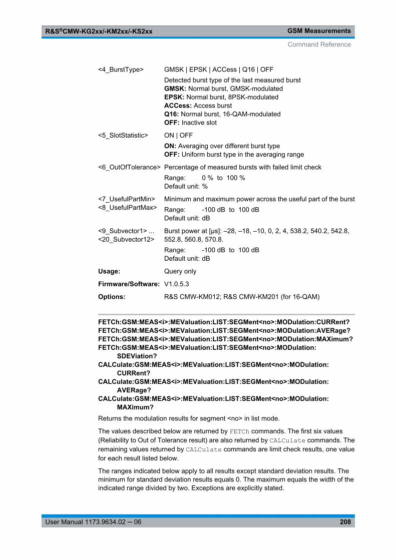
GSM MeasurementsR&S®CMW-KG2xx/-KM2xx/-KS2xx
208User Manual 1173.9634.02 ─ 06
<4_BurstType> GMSK | EPSK | ACCess | Q16 | OFFDetected burst type of the last measured burstGMSK: Normal burst, GMSK-modulatedEPSK: Normal burst, 8PSK-modulatedACCess: Access burstQ16: Normal burst, 16-QAM-modulatedOFF: Inactive slot
<5_SlotStatistic> ON | OFFON: Averaging over different burst typeOFF: Uniform burst type in the averaging range
<6_OutOfTolerance> Percentage of measured bursts with failed limit checkRange: 0 % to 100 %Default unit: %
<7_UsefulPartMin><8_UsefulPartMax>
Minimum and maximum power across the useful part of the burstRange: -100 dB to 100 dBDefault unit: dB
<9_Subvector1> ...<20_Subvector12>
Burst power at [μs]: –28, –18, –10, 0, 2, 4, 538.2, 540.2, 542.8,552.8, 560.8, 570.8.Range: -100 dB to 100 dBDefault unit: dB
Usage: Query only
Firmware/Software: V1.0.5.3
Options: R&S CMW-KM012; R&S CMW-KM201 (for 16-QAM)
FETCh:GSM:MEAS<i>:MEValuation:LIST:SEGMent<no>:MODulation:CURRent?FETCh:GSM:MEAS<i>:MEValuation:LIST:SEGMent<no>:MODulation:AVERage?FETCh:GSM:MEAS<i>:MEValuation:LIST:SEGMent<no>:MODulation:MAXimum?FETCh:GSM:MEAS<i>:MEValuation:LIST:SEGMent<no>:MODulation:
SDEViation?CALCulate:GSM:MEAS<i>:MEValuation:LIST:SEGMent<no>:MODulation:
CURRent?CALCulate:GSM:MEAS<i>:MEValuation:LIST:SEGMent<no>:MODulation:
AVERage?CALCulate:GSM:MEAS<i>:MEValuation:LIST:SEGMent<no>:MODulation:
MAXimum?Returns the modulation results for segment <no> in list mode.
The values described below are returned by FETCh commands. The first six values(Reliability to Out of Tolerance result) are also returned by CALCulate commands. Theremaining values returned by CALCulate commands are limit check results, one valuefor each result listed below.
The ranges indicated below apply to all results except standard deviation results. Theminimum for standard deviation results equals 0. The maximum equals the width of theindicated range divided by two. Exceptions are explicitly stated.
Command Reference
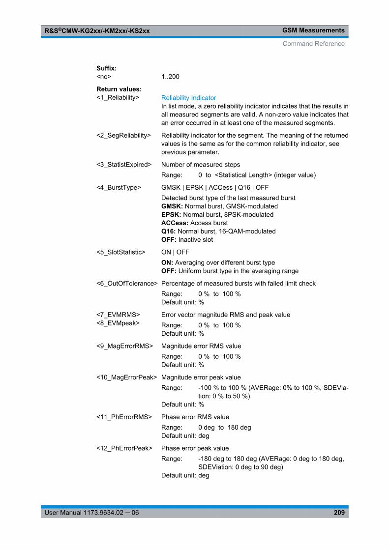
GSM MeasurementsR&S®CMW-KG2xx/-KM2xx/-KS2xx
209User Manual 1173.9634.02 ─ 06
Suffix: <no>
.1..200
Return values: <1_Reliability> Reliability Indicator
In list mode, a zero reliability indicator indicates that the results inall measured segments are valid. A non-zero value indicates thatan error occurred in at least one of the measured segments.
<2_SegReliability> Reliability indicator for the segment. The meaning of the returnedvalues is the same as for the common reliability indicator, seeprevious parameter.
<3_StatistExpired> Number of measured stepsRange: 0 to <Statistical Length> (integer value)
<4_BurstType> GMSK | EPSK | ACCess | Q16 | OFFDetected burst type of the last measured burstGMSK: Normal burst, GMSK-modulatedEPSK: Normal burst, 8PSK-modulatedACCess: Access burstQ16: Normal burst, 16-QAM-modulatedOFF: Inactive slot
<5_SlotStatistic> ON | OFFON: Averaging over different burst typeOFF: Uniform burst type in the averaging range
<6_OutOfTolerance> Percentage of measured bursts with failed limit checkRange: 0 % to 100 %Default unit: %
<7_EVMRMS><8_EVMpeak>
Error vector magnitude RMS and peak valueRange: 0 % to 100 %Default unit: %
<9_MagErrorRMS> Magnitude error RMS valueRange: 0 % to 100 %Default unit: %
<10_MagErrorPeak> Magnitude error peak valueRange: -100 % to 100 % (AVERage: 0% to 100 %, SDEVia-
tion: 0 % to 50 %)Default unit: %
<11_PhErrorRMS> Phase error RMS valueRange: 0 deg to 180 degDefault unit: deg
<12_PhErrorPeak> Phase error peak valueRange: -180 deg to 180 deg (AVERage: 0 deg to 180 deg,
SDEViation: 0 deg to 90 deg)Default unit: deg
Command Reference
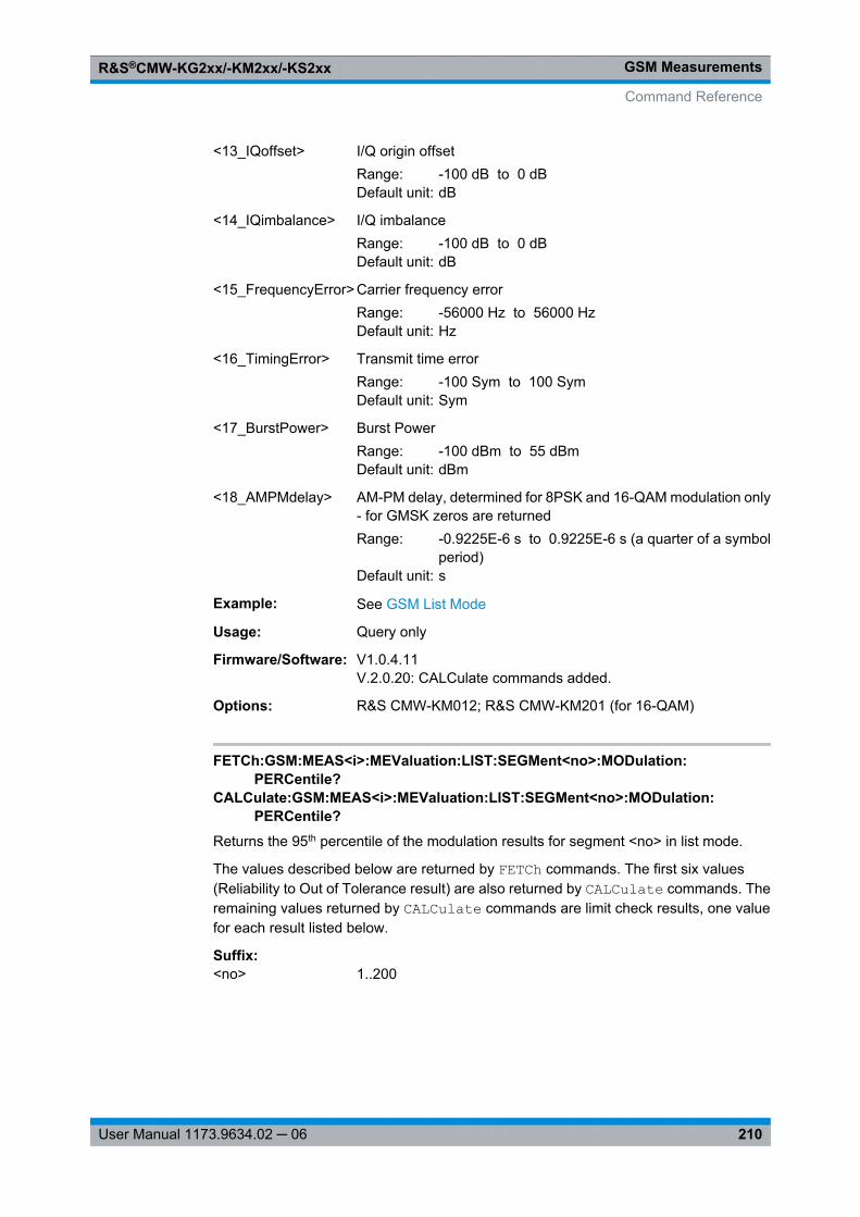
GSM MeasurementsR&S®CMW-KG2xx/-KM2xx/-KS2xx
210User Manual 1173.9634.02 ─ 06
<13_IQoffset> I/Q origin offsetRange: -100 dB to 0 dBDefault unit: dB
<14_IQimbalance> I/Q imbalanceRange: -100 dB to 0 dBDefault unit: dB
<15_FrequencyError> Carrier frequency errorRange: -56000 Hz to 56000 HzDefault unit: Hz
<16_TimingError> Transmit time errorRange: -100 Sym to 100 SymDefault unit: Sym
<17_BurstPower> Burst PowerRange: -100 dBm to 55 dBmDefault unit: dBm
<18_AMPMdelay> AM-PM delay, determined for 8PSK and 16-QAM modulation only- for GMSK zeros are returnedRange: -0.9225E-6 s to 0.9225E-6 s (a quarter of a symbol
period)Default unit: s
Example: See GSM List Mode
Usage: Query only
Firmware/Software: V1.0.4.11V.2.0.20: CALCulate commands added.
Options: R&S CMW-KM012; R&S CMW-KM201 (for 16-QAM)
FETCh:GSM:MEAS<i>:MEValuation:LIST:SEGMent<no>:MODulation:PERCentile?
CALCulate:GSM:MEAS<i>:MEValuation:LIST:SEGMent<no>:MODulation:PERCentile?
Returns the 95th percentile of the modulation results for segment <no> in list mode.
The values described below are returned by FETCh commands. The first six values(Reliability to Out of Tolerance result) are also returned by CALCulate commands. Theremaining values returned by CALCulate commands are limit check results, one valuefor each result listed below.
Suffix: <no>
.1..200
Command Reference
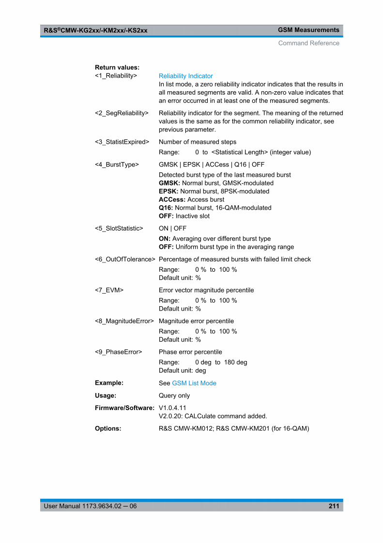
GSM MeasurementsR&S®CMW-KG2xx/-KM2xx/-KS2xx
211User Manual 1173.9634.02 ─ 06
Return values: <1_Reliability> Reliability Indicator
In list mode, a zero reliability indicator indicates that the results inall measured segments are valid. A non-zero value indicates thatan error occurred in at least one of the measured segments.
<2_SegReliability> Reliability indicator for the segment. The meaning of the returnedvalues is the same as for the common reliability indicator, seeprevious parameter.
<3_StatistExpired> Number of measured stepsRange: 0 to <Statistical Length> (integer value)
<4_BurstType> GMSK | EPSK | ACCess | Q16 | OFFDetected burst type of the last measured burstGMSK: Normal burst, GMSK-modulatedEPSK: Normal burst, 8PSK-modulatedACCess: Access burstQ16: Normal burst, 16-QAM-modulatedOFF: Inactive slot
<5_SlotStatistic> ON | OFFON: Averaging over different burst typeOFF: Uniform burst type in the averaging range
<6_OutOfTolerance> Percentage of measured bursts with failed limit checkRange: 0 % to 100 %Default unit: %
<7_EVM> Error vector magnitude percentileRange: 0 % to 100 %Default unit: %
<8_MagnitudeError> Magnitude error percentileRange: 0 % to 100 %Default unit: %
<9_PhaseError> Phase error percentileRange: 0 deg to 180 degDefault unit: deg
Example: See GSM List Mode
Usage: Query only
Firmware/Software: V1.0.4.11V2.0.20: CALCulate command added.
Options: R&S CMW-KM012; R&S CMW-KM201 (for 16-QAM)
Command Reference
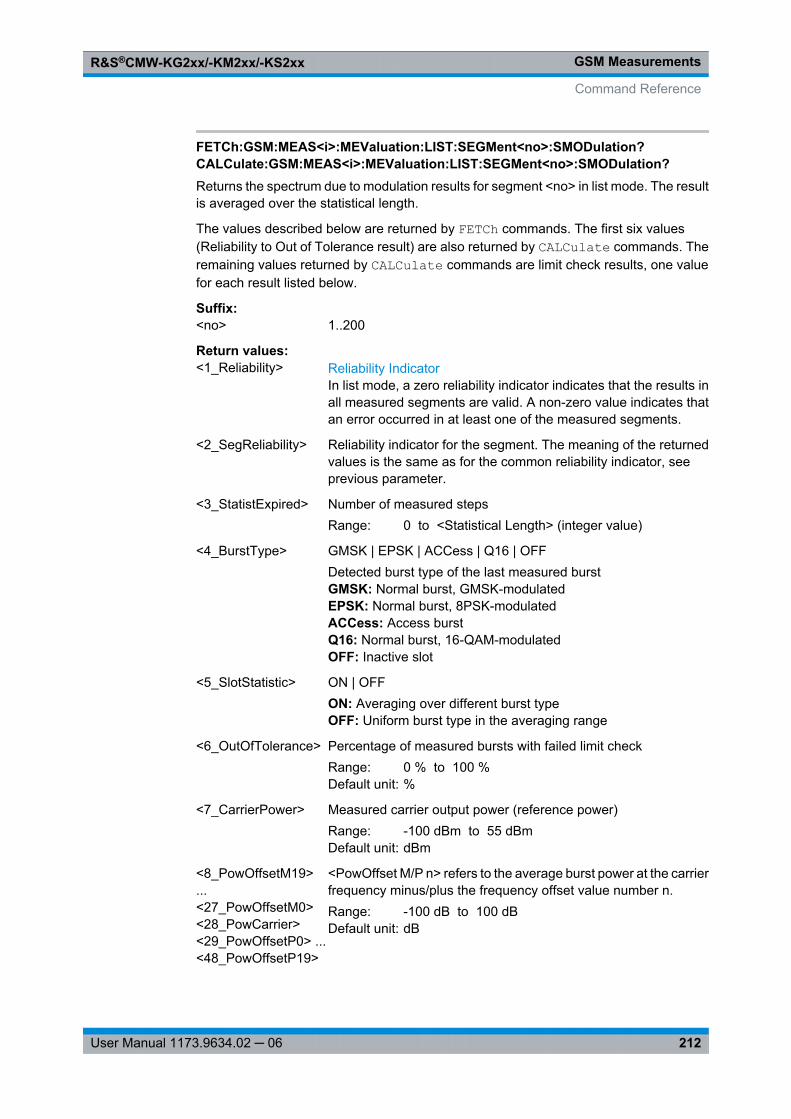
GSM MeasurementsR&S®CMW-KG2xx/-KM2xx/-KS2xx
212User Manual 1173.9634.02 ─ 06
FETCh:GSM:MEAS<i>:MEValuation:LIST:SEGMent<no>:SMODulation?CALCulate:GSM:MEAS<i>:MEValuation:LIST:SEGMent<no>:SMODulation?Returns the spectrum due to modulation results for segment <no> in list mode. The resultis averaged over the statistical length.
The values described below are returned by FETCh commands. The first six values(Reliability to Out of Tolerance result) are also returned by CALCulate commands. Theremaining values returned by CALCulate commands are limit check results, one valuefor each result listed below.
Suffix: <no>
.1..200
Return values: <1_Reliability> Reliability Indicator
In list mode, a zero reliability indicator indicates that the results inall measured segments are valid. A non-zero value indicates thatan error occurred in at least one of the measured segments.
<2_SegReliability> Reliability indicator for the segment. The meaning of the returnedvalues is the same as for the common reliability indicator, seeprevious parameter.
<3_StatistExpired> Number of measured stepsRange: 0 to <Statistical Length> (integer value)
<4_BurstType> GMSK | EPSK | ACCess | Q16 | OFFDetected burst type of the last measured burstGMSK: Normal burst, GMSK-modulatedEPSK: Normal burst, 8PSK-modulatedACCess: Access burstQ16: Normal burst, 16-QAM-modulatedOFF: Inactive slot
<5_SlotStatistic> ON | OFFON: Averaging over different burst typeOFF: Uniform burst type in the averaging range
<6_OutOfTolerance> Percentage of measured bursts with failed limit checkRange: 0 % to 100 %Default unit: %
<7_CarrierPower> Measured carrier output power (reference power)Range: -100 dBm to 55 dBmDefault unit: dBm
<8_PowOffsetM19>...<27_PowOffsetM0><28_PowCarrier><29_PowOffsetP0> ...<48_PowOffsetP19>
<PowOffset M/P n> refers to the average burst power at the carrierfrequency minus/plus the frequency offset value number n.Range: -100 dB to 100 dBDefault unit: dB
Command Reference
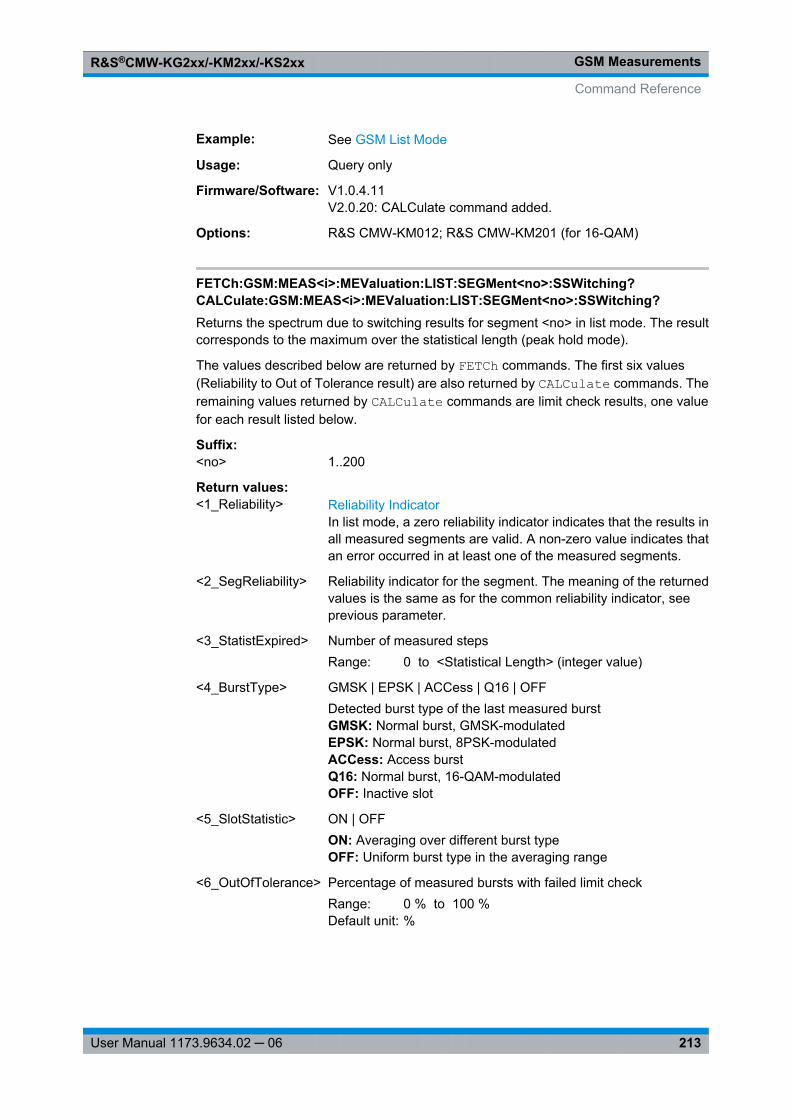
GSM MeasurementsR&S®CMW-KG2xx/-KM2xx/-KS2xx
213User Manual 1173.9634.02 ─ 06
Example: See GSM List Mode
Usage: Query only
Firmware/Software: V1.0.4.11V2.0.20: CALCulate command added.
Options: R&S CMW-KM012; R&S CMW-KM201 (for 16-QAM)
FETCh:GSM:MEAS<i>:MEValuation:LIST:SEGMent<no>:SSWitching?CALCulate:GSM:MEAS<i>:MEValuation:LIST:SEGMent<no>:SSWitching?Returns the spectrum due to switching results for segment <no> in list mode. The resultcorresponds to the maximum over the statistical length (peak hold mode).
The values described below are returned by FETCh commands. The first six values(Reliability to Out of Tolerance result) are also returned by CALCulate commands. Theremaining values returned by CALCulate commands are limit check results, one valuefor each result listed below.
Suffix: <no>
.1..200
Return values: <1_Reliability> Reliability Indicator
In list mode, a zero reliability indicator indicates that the results inall measured segments are valid. A non-zero value indicates thatan error occurred in at least one of the measured segments.
<2_SegReliability> Reliability indicator for the segment. The meaning of the returnedvalues is the same as for the common reliability indicator, seeprevious parameter.
<3_StatistExpired> Number of measured stepsRange: 0 to <Statistical Length> (integer value)
<4_BurstType> GMSK | EPSK | ACCess | Q16 | OFFDetected burst type of the last measured burstGMSK: Normal burst, GMSK-modulatedEPSK: Normal burst, 8PSK-modulatedACCess: Access burstQ16: Normal burst, 16-QAM-modulatedOFF: Inactive slot
<5_SlotStatistic> ON | OFFON: Averaging over different burst typeOFF: Uniform burst type in the averaging range
<6_OutOfTolerance> Percentage of measured bursts with failed limit checkRange: 0 % to 100 %Default unit: %
Command Reference
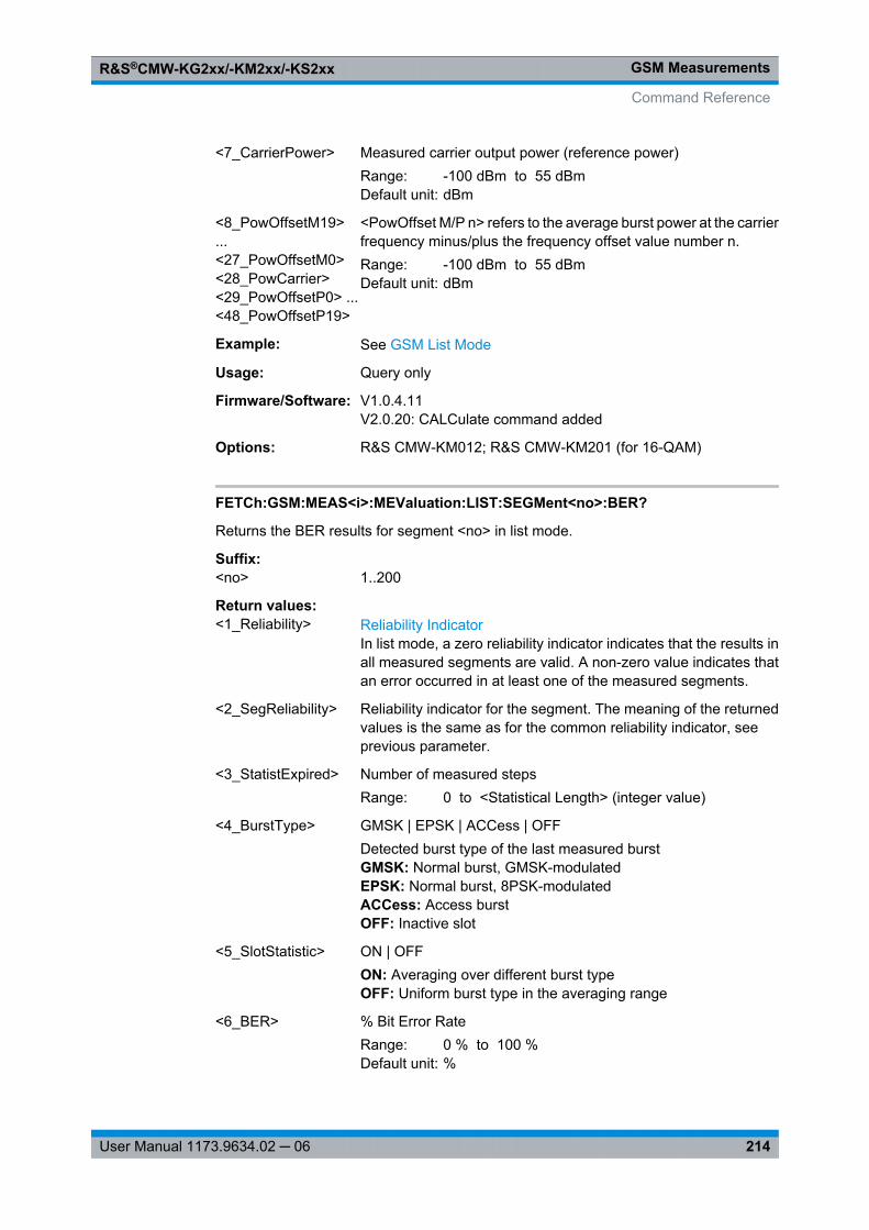
GSM MeasurementsR&S®CMW-KG2xx/-KM2xx/-KS2xx
214User Manual 1173.9634.02 ─ 06
<7_CarrierPower> Measured carrier output power (reference power)Range: -100 dBm to 55 dBmDefault unit: dBm
<8_PowOffsetM19>...<27_PowOffsetM0><28_PowCarrier><29_PowOffsetP0> ...<48_PowOffsetP19>
<PowOffset M/P n> refers to the average burst power at the carrierfrequency minus/plus the frequency offset value number n.Range: -100 dBm to 55 dBmDefault unit: dBm
Example: See GSM List Mode
Usage: Query only
Firmware/Software: V1.0.4.11V2.0.20: CALCulate command added
Options: R&S CMW-KM012; R&S CMW-KM201 (for 16-QAM)
FETCh:GSM:MEAS<i>:MEValuation:LIST:SEGMent<no>:BER?
Returns the BER results for segment <no> in list mode.
Suffix: <no>
.1..200
Return values: <1_Reliability> Reliability Indicator
In list mode, a zero reliability indicator indicates that the results inall measured segments are valid. A non-zero value indicates thatan error occurred in at least one of the measured segments.
<2_SegReliability> Reliability indicator for the segment. The meaning of the returnedvalues is the same as for the common reliability indicator, seeprevious parameter.
<3_StatistExpired> Number of measured stepsRange: 0 to <Statistical Length> (integer value)
<4_BurstType> GMSK | EPSK | ACCess | OFFDetected burst type of the last measured burstGMSK: Normal burst, GMSK-modulatedEPSK: Normal burst, 8PSK-modulatedACCess: Access burstOFF: Inactive slot
<5_SlotStatistic> ON | OFFON: Averaging over different burst typeOFF: Uniform burst type in the averaging range
<6_BER> % Bit Error RateRange: 0 % to 100 %Default unit: %
Command Reference
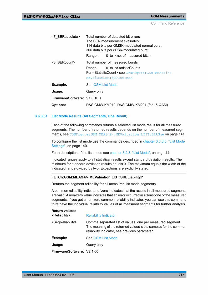
GSM MeasurementsR&S®CMW-KG2xx/-KM2xx/-KS2xx
215User Manual 1173.9634.02 ─ 06
<7_BERabsolute> Total number of detected bit errorsThe BER measurement evaluates:114 data bits per GMSK-modulated normal burst306 data bits per 8PSK-modulated burst.Range: 0 to <no. of measured bits>
<8_BERcount> Total number of measured burstsRange: 0 to <StatisticCount>For <StatisticCount> see CONFigure: GSM: MEAS<i>: MEValuation: SCOunt: BER
Example: See GSM List Mode
Usage: Query only
Firmware/Software: V1.0.10.1
Options: R&S CMW-KM012; R&S CMW-KM201 (for 16-QAM)
3.6.3.31 List Mode Results (All Segments, One Result)
Each of the following commands returns a selected list mode result for all measuredsegments. The number of returned results depends on the number of measured seg-ments, see CONFigure: GSM: MEAS<i>: MEValuation: LIST: LRANge on page 141.
To configure the list mode use the commands described in chapter 3.6.3.5, "List ModeSettings", on page 140.
For a description of the list mode see chapter 3.2.3, "List Mode", on page 44.
Indicated ranges apply to all statistical results except standard deviation results. Theminimum for standard deviation results equals 0. The maximum equals the width of theindicated range divided by two. Exceptions are explicitly stated.
FETCh:GSM:MEAS<i>:MEValuation:LIST:SRELiability?
Returns the segment reliability for all measured list mode segments.
A common reliability indicator of zero indicates that the results in all measured segmentsare valid. A non-zero value indicates that an error occurred in at least one of the measuredsegments. If you get a non-zero common reliability indicator, you can use this commandto retrieve the individual reliability values of all measured segments for further analysis.
Return values: <Reliability> Reliability Indicator
<SegReliability> Comma separated list of values, one per measured segmentThe meaning of the returned values is the same as for the commonreliability indicator, see previous parameter.
Example: See GSM List Mode
Usage: Query only
Firmware/Software: V2.1.60
Command Reference
GSM MeasurementsR&S®CMW-KG2xx/-KM2xx/-KS2xx
216User Manual 1173.9634.02 ─ 06
Options: R&S CMW-KM012
CALCulate:GSM:MEAS<i>:MEValuation:LIST:PVTime:ABPower:CURRent?CALCulate:GSM:MEAS<i>:MEValuation:LIST:PVTime:ABPower:AVERage?FETCh:GSM:MEAS<i>:MEValuation:LIST:PVTime:ABPower:CURRent?FETCh:GSM:MEAS<i>:MEValuation:LIST:PVTime:ABPower:AVERage?Return average burst power results for all measured list mode segments.
The values described below are returned by FETCh commands. CALCulate commandsreturn limit check results instead, one value for each result listed below.
Return values: <Reliability> Reliability Indicator
<AverageBurstPow> Comma separated list of values, one per measured segmentRange: -100 dBm to 55 dBmDefault unit: dBm
Example: See GSM List Mode
Usage: Query only
Firmware/Software: V2.1.60
Options: R&S CMW-KM012
FETCh:GSM:MEAS<i>:MEValuation:LIST:PVTime:SVECtor:UMAXimum:CURRent?
FETCh:GSM:MEAS<i>:MEValuation:LIST:PVTime:SVECtor:UMAXimum:AVERage?
FETCh:GSM:MEAS<i>:MEValuation:LIST:PVTime:SVECtor:UMAXimum:MINimum?
FETCh:GSM:MEAS<i>:MEValuation:LIST:PVTime:SVECtor:UMAXimum:MAXimum?
Return maximum power across the useful part of the burst for all measured list modesegments.
Return values: <Reliability> Reliability Indicator
<UsefullPartMax> Comma separated list of values, one per measured segmentRange: -100 dB to 100 dBDefault unit: dB
Example: See GSM List Mode
Usage: Query only
Firmware/Software: V2.1.60
Options: R&S CMW-KM012
Command Reference
GSM MeasurementsR&S®CMW-KG2xx/-KM2xx/-KS2xx
217User Manual 1173.9634.02 ─ 06
FETCh:GSM:MEAS<i>:MEValuation:LIST:PVTime:SVECtor:UMINimum:CURRent?
FETCh:GSM:MEAS<i>:MEValuation:LIST:PVTime:SVECtor:UMINimum:AVERage?
FETCh:GSM:MEAS<i>:MEValuation:LIST:PVTime:SVECtor:UMINimum:MINimum?
FETCh:GSM:MEAS<i>:MEValuation:LIST:PVTime:SVECtor:UMINimum:MAXimum?
Return minimum power across the useful part of the burst for all measured list modesegments.
Return values: <Reliability> Reliability Indicator
<UsefullPartMin> Comma separated list of values, one per measured segmentRange: -100 dB to 100 dBDefault unit: dB
Example: See GSM List Mode
Usage: Query only
Firmware/Software: V2.1.60
Options: R&S CMW-KM012
FETCh:GSM:MEAS<i>:MEValuation:LIST:PVTime:SVECtor:SUBVector<no>:CURRent?
FETCh:GSM:MEAS<i>:MEValuation:LIST:PVTime:SVECtor:SUBVector<no>:AVERage?
FETCh:GSM:MEAS<i>:MEValuation:LIST:PVTime:SVECtor:SUBVector<no>:MINimum?
FETCh:GSM:MEAS<i>:MEValuation:LIST:PVTime:SVECtor:SUBVector<no>:MAXimum?
Return burst power at a specific burst position for all measured list mode segments.
Suffix: <no>
.1..12Index selecting one of the following burst positions [µs]: –28, –18,–10, 0, 2, 4, 538.2, 540.2, 542.8, 552.8, 560.8, 570.8
Return values: <Reliability> Reliability Indicator
<Subvector> Comma separated list of values, one per measured segmentRange: -100 dB to 100 dBDefault unit: dB
Example: See GSM List Mode
Usage: Query only
Firmware/Software: V2.1.60
Command Reference
GSM MeasurementsR&S®CMW-KG2xx/-KM2xx/-KS2xx
218User Manual 1173.9634.02 ─ 06
Options: R&S CMW-KM012
CALCulate:GSM:MEAS<i>:MEValuation:LIST:MODulation:EVM:RMS:CURRent?CALCulate:GSM:MEAS<i>:MEValuation:LIST:MODulation:EVM:RMS:AVERage?CALCulate:GSM:MEAS<i>:MEValuation:LIST:MODulation:EVM:RMS:MAXimum?FETCh:GSM:MEAS<i>:MEValuation:LIST:MODulation:EVM:RMS:CURRent?FETCh:GSM:MEAS<i>:MEValuation:LIST:MODulation:EVM:RMS:AVERage?FETCh:GSM:MEAS<i>:MEValuation:LIST:MODulation:EVM:RMS:MAXimum?FETCh:GSM:MEAS<i>:MEValuation:LIST:MODulation:EVM:RMS:SDEViation?Return error vector magnitude RMS values for all measured list mode segments.
The values described below are returned by FETCh commands. CALCulate commandsreturn limit check results instead, one value for each result listed below.
Return values: <Reliability> Reliability Indicator
<EVM_RMS> Comma separated list of values, one per measured segmentRange: 0 % to 100 %Default unit: %
Example: See GSM List Mode
Usage: Query only
Firmware/Software: V2.1.60
Options: R&S CMW-KM012
CALCulate:GSM:MEAS<i>:MEValuation:LIST:MODulation:EVM:PEAK:CURRent?CALCulate:GSM:MEAS<i>:MEValuation:LIST:MODulation:EVM:PEAK:AVERage?CALCulate:GSM:MEAS<i>:MEValuation:LIST:MODulation:EVM:PEAK:
MAXimum?FETCh:GSM:MEAS<i>:MEValuation:LIST:MODulation:EVM:PEAK:CURRent?FETCh:GSM:MEAS<i>:MEValuation:LIST:MODulation:EVM:PEAK:AVERage?FETCh:GSM:MEAS<i>:MEValuation:LIST:MODulation:EVM:PEAK:MAXimum?FETCh:GSM:MEAS<i>:MEValuation:LIST:MODulation:EVM:PEAK:SDEViation?Return error vector magnitude peak values for all measured list mode segments.
The values described below are returned by FETCh commands. CALCulate commandsreturn limit check results instead, one value for each result listed below.
Return values: <Reliability> Reliability Indicator
<EVMpeak> Comma separated list of values, one per measured segmentRange: 0 % to 100 %Default unit: %
Example: See GSM List Mode
Usage: Query only
Command Reference
GSM MeasurementsR&S®CMW-KG2xx/-KM2xx/-KS2xx
219User Manual 1173.9634.02 ─ 06
Firmware/Software: V2.1.60
Options: R&S CMW-KM012
CALCulate:GSM:MEAS<i>:MEValuation:LIST:MODulation:EVM:PERCentile?FETCh:GSM:MEAS<i>:MEValuation:LIST:MODulation:EVM:PERCentile?Return error vector magnitude 95th percentile values for all measured list mode segments.
The values described below are returned by FETCh commands. CALCulate commandsreturn limit check results instead, one value for each result listed below.
Return values: <Reliability> Reliability Indicator
<EVM> Comma separated list of values, one per measured segmentRange: 0 % to 100 %Default unit: %
Example: See GSM List Mode
Usage: Query only
Firmware/Software: V2.1.60
Options: R&S CMW-KM012
CALCulate:GSM:MEAS<i>:MEValuation:LIST:MODulation:MERRor:RMS:CURRent?
CALCulate:GSM:MEAS<i>:MEValuation:LIST:MODulation:MERRor:RMS:AVERage?
CALCulate:GSM:MEAS<i>:MEValuation:LIST:MODulation:MERRor:RMS:MAXimum?
FETCh:GSM:MEAS<i>:MEValuation:LIST:MODulation:MERRor:RMS:CURRent?FETCh:GSM:MEAS<i>:MEValuation:LIST:MODulation:MERRor:RMS:AVERage?FETCh:GSM:MEAS<i>:MEValuation:LIST:MODulation:MERRor:RMS:MAXimum?FETCh:GSM:MEAS<i>:MEValuation:LIST:MODulation:MERRor:RMS:SDEViation?Return magnitude error RMS values for all measured list mode segments.
The values described below are returned by FETCh commands. CALCulate commandsreturn limit check results instead, one value for each result listed below.
Return values: <Reliability> Reliability Indicator
<MagErrorRMS> Comma separated list of values, one per measured segmentRange: 0 % to 100 %Default unit: %
Example: See GSM List Mode
Usage: Query only
Firmware/Software: V2.1.60
Command Reference
GSM MeasurementsR&S®CMW-KG2xx/-KM2xx/-KS2xx
220User Manual 1173.9634.02 ─ 06
Options: R&S CMW-KM012
CALCulate:GSM:MEAS<i>:MEValuation:LIST:MODulation:MERRor:PEAK:CURRent?
CALCulate:GSM:MEAS<i>:MEValuation:LIST:MODulation:MERRor:PEAK:AVERage?
CALCulate:GSM:MEAS<i>:MEValuation:LIST:MODulation:MERRor:PEAK:MAXimum?
FETCh:GSM:MEAS<i>:MEValuation:LIST:MODulation:MERRor:PEAK:CURRent?FETCh:GSM:MEAS<i>:MEValuation:LIST:MODulation:MERRor:PEAK:AVERage?FETCh:GSM:MEAS<i>:MEValuation:LIST:MODulation:MERRor:PEAK:MAXimum?FETCh:GSM:MEAS<i>:MEValuation:LIST:MODulation:MERRor:PEAK:
SDEViation?Return magnitude error peak values for all measured list mode segments.
The values described below are returned by FETCh commands. CALCulate commandsreturn limit check results instead, one value for each result listed below.
Return values: <Reliability> Reliability Indicator
<MagErrorPeak> Comma separated list of values, one per measured segmentRange: -100 % to 100 % (AVERage: 0 % to 100 %, SDEVi-
ation: 0 % to 50 %)Default unit: %
Example: See GSM List Mode
Usage: Query only
Firmware/Software: V2.1.60
Options: R&S CMW-KM012
CALCulate:GSM:MEAS<i>:MEValuation:LIST:MODulation:MERRor:PERCentile?FETCh:GSM:MEAS<i>:MEValuation:LIST:MODulation:MERRor:PERCentile?Return magnitude error 95th percentile values for all measured list mode segments.
The values described below are returned by FETCh commands. CALCulate commandsreturn limit check results instead, one value for each result listed below.
Return values: <Reliability> Reliability Indicator
<MagnitudeError> Comma separated list of values, one per measured segmentRange: 0 % to 100 %Default unit: %
Example: See GSM List Mode
Usage: Query only
Firmware/Software: V2.1.60
Command Reference
GSM MeasurementsR&S®CMW-KG2xx/-KM2xx/-KS2xx
221User Manual 1173.9634.02 ─ 06
Options: R&S CMW-KM012
CALCulate:GSM:MEAS<i>:MEValuation:LIST:MODulation:PERRor:RMS:CURRent?
CALCulate:GSM:MEAS<i>:MEValuation:LIST:MODulation:PERRor:RMS:AVERage?
CALCulate:GSM:MEAS<i>:MEValuation:LIST:MODulation:PERRor:RMS:MAXimum?
FETCh:GSM:MEAS<i>:MEValuation:LIST:MODulation:PERRor:RMS:CURRent?FETCh:GSM:MEAS<i>:MEValuation:LIST:MODulation:PERRor:RMS:AVERage?FETCh:GSM:MEAS<i>:MEValuation:LIST:MODulation:PERRor:RMS:MAXimum?FETCh:GSM:MEAS<i>:MEValuation:LIST:MODulation:PERRor:RMS:SDEViation?Return phase error RMS values for all measured list mode segments.
The values described below are returned by FETCh commands. CALCulate commandsreturn limit check results instead, one value for each result listed below.
Return values: <Reliability> Reliability Indicator
<PhaseErrorRMS> Comma separated list of values, one per measured segmentRange: 0 deg to 180 degDefault unit: deg
Example: See GSM List Mode
Usage: Query only
Firmware/Software: V2.1.60
Options: R&S CMW-KM012
CALCulate:GSM:MEAS<i>:MEValuation:LIST:MODulation:PERRor:PEAK:CURRent?
CALCulate:GSM:MEAS<i>:MEValuation:LIST:MODulation:PERRor:PEAK:AVERage?
CALCulate:GSM:MEAS<i>:MEValuation:LIST:MODulation:PERRor:PEAK:MAXimum?
FETCh:GSM:MEAS<i>:MEValuation:LIST:MODulation:PERRor:PEAK:CURRent?FETCh:GSM:MEAS<i>:MEValuation:LIST:MODulation:PERRor:PEAK:AVERage?FETCh:GSM:MEAS<i>:MEValuation:LIST:MODulation:PERRor:PEAK:MAXimum?FETCh:GSM:MEAS<i>:MEValuation:LIST:MODulation:PERRor:PEAK:
SDEViation?Return phase error peak values for all measured list mode segments.
The values described below are returned by FETCh commands. CALCulate commandsreturn limit check results instead, one value for each result listed below.
Return values: <Reliability> Reliability Indicator
Command Reference
GSM MeasurementsR&S®CMW-KG2xx/-KM2xx/-KS2xx
222User Manual 1173.9634.02 ─ 06
<PhaseErrorPeak> Comma separated list of values, one per measured segmentRange: -180 deg to 180 deg (AVERage: 0 deg to 180 deg,
SDEViation: 0 deg to 90 deg)Default unit: deg
Example: See GSM List Mode
Usage: Query only
Firmware/Software: V2.1.60
Options: R&S CMW-KM012
CALCulate:GSM:MEAS<i>:MEValuation:LIST:MODulation:PERRor:PERCentile?FETCh:GSM:MEAS<i>:MEValuation:LIST:MODulation:PERRor:PERCentile?Return phase error 95th percentile values for all measured list mode segments.
The values described below are returned by FETCh commands. CALCulate commandsreturn limit check results instead, one value for each result listed below.
Return values: <Reliability> Reliability Indicator
<PhaseError> Comma separated list of values, one per measured segmentRange: 0 deg to 180 degDefault unit: deg
Example: See GSM List Mode
Usage: Query only
Firmware/Software: V2.1.60
Options: R&S CMW-KM012
CALCulate:GSM:MEAS<i>:MEValuation:LIST:MODulation:IQOFfset:CURRent?CALCulate:GSM:MEAS<i>:MEValuation:LIST:MODulation:IQOFfset:AVERage?CALCulate:GSM:MEAS<i>:MEValuation:LIST:MODulation:IQOFfset:MAXimum?FETCh:GSM:MEAS<i>:MEValuation:LIST:MODulation:IQOFfset:CURRent?FETCh:GSM:MEAS<i>:MEValuation:LIST:MODulation:IQOFfset:AVERage?FETCh:GSM:MEAS<i>:MEValuation:LIST:MODulation:IQOFfset:MAXimum?FETCh:GSM:MEAS<i>:MEValuation:LIST:MODulation:IQOFfset:SDEViation?Return I/Q origin offset results for all measured list mode segments.
The values described below are returned by FETCh commands. CALCulate commandsreturn limit check results instead, one value for each result listed below.
Return values: <Reliability> Reliability Indicator
<IQoffset> Comma separated list of values, one per measured segmentRange: -100 dB to 0 dBDefault unit: dB
Command Reference
GSM MeasurementsR&S®CMW-KG2xx/-KM2xx/-KS2xx
223User Manual 1173.9634.02 ─ 06
Example: See GSM List Mode
Usage: Query only
Firmware/Software: V2.1.60
Options: R&S CMW-KM012
CALCulate:GSM:MEAS<i>:MEValuation:LIST:MODulation:IQIMbalance:CURRent?
CALCulate:GSM:MEAS<i>:MEValuation:LIST:MODulation:IQIMbalance:AVERage?
CALCulate:GSM:MEAS<i>:MEValuation:LIST:MODulation:IQIMbalance:MAXimum?
FETCh:GSM:MEAS<i>:MEValuation:LIST:MODulation:IQIMbalance:CURRent?FETCh:GSM:MEAS<i>:MEValuation:LIST:MODulation:IQIMbalance:AVERage?FETCh:GSM:MEAS<i>:MEValuation:LIST:MODulation:IQIMbalance:MAXimum?FETCh:GSM:MEAS<i>:MEValuation:LIST:MODulation:IQIMbalance:SDEViation?Return I/Q imbalance results for all measured list mode segments.
The values described below are returned by FETCh commands. CALCulate commandsreturn limit check results instead, one value for each result listed below.
Return values: <Reliability> Reliability Indicator
<IQimbalance> Comma separated list of values, one per measured segmentRange: -100 dB to 0 dBDefault unit: dB
Example: See GSM List Mode
Usage: Query only
Firmware/Software: V2.1.60
Options: R&S CMW-KM012
CALCulate:GSM:MEAS<i>:MEValuation:LIST:MODulation:FERRor:CURRent?CALCulate:GSM:MEAS<i>:MEValuation:LIST:MODulation:FERRor:AVERage?CALCulate:GSM:MEAS<i>:MEValuation:LIST:MODulation:FERRor:MAXimum?FETCh:GSM:MEAS<i>:MEValuation:LIST:MODulation:FERRor:CURRent?FETCh:GSM:MEAS<i>:MEValuation:LIST:MODulation:FERRor:AVERage?FETCh:GSM:MEAS<i>:MEValuation:LIST:MODulation:FERRor:MAXimum?FETCh:GSM:MEAS<i>:MEValuation:LIST:MODulation:FERRor:SDEViation?Return carrier frequency error results for all measured list mode segments.
The values described below are returned by FETCh commands. CALCulate commandsreturn limit check results instead, one value for each result listed below.
Return values: <Reliability> Reliability Indicator
Command Reference
GSM MeasurementsR&S®CMW-KG2xx/-KM2xx/-KS2xx
224User Manual 1173.9634.02 ─ 06
<FrequencyError> Comma separated list of values, one per measured segmentRange: -56000 Hz to 56000 HzDefault unit: Hz
Example: See GSM List Mode
Usage: Query only
Firmware/Software: V2.1.60
Options: R&S CMW-KM012
CALCulate:GSM:MEAS<i>:MEValuation:LIST:MODulation:TERRor:CURRent?CALCulate:GSM:MEAS<i>:MEValuation:LIST:MODulation:TERRor:AVERage?CALCulate:GSM:MEAS<i>:MEValuation:LIST:MODulation:TERRor:MAXimum?FETCh:GSM:MEAS<i>:MEValuation:LIST:MODulation:TERRor:CURRent?FETCh:GSM:MEAS<i>:MEValuation:LIST:MODulation:TERRor:AVERage?FETCh:GSM:MEAS<i>:MEValuation:LIST:MODulation:TERRor:MAXimum?FETCh:GSM:MEAS<i>:MEValuation:LIST:MODulation:TERRor:SDEViation?Return transmit time error values for all measured list mode segments.
The values described below are returned by FETCh commands. CALCulate commandsreturn limit check results instead, one value for each result listed below.
Return values: <Reliability> Reliability Indicator
<TimingError> Comma separated list of values, one per measured segmentRange: -100 Sym to 100 SymDefault unit: Sym
Example: See GSM List Mode
Usage: Query only
Firmware/Software: V2.1.60
Options: R&S CMW-KM012
CALCulate:GSM:MEAS<i>:MEValuation:LIST:MODulation:BPOWer:CURRent?CALCulate:GSM:MEAS<i>:MEValuation:LIST:MODulation:BPOWer:AVERage?CALCulate:GSM:MEAS<i>:MEValuation:LIST:MODulation:BPOWer:MAXimum?FETCh:GSM:MEAS<i>:MEValuation:LIST:MODulation:BPOWer:CURRent?FETCh:GSM:MEAS<i>:MEValuation:LIST:MODulation:BPOWer:AVERage?FETCh:GSM:MEAS<i>:MEValuation:LIST:MODulation:BPOWer:MAXimum?FETCh:GSM:MEAS<i>:MEValuation:LIST:MODulation:BPOWer:SDEViation?Return burst power values for all measured list mode segments.
The values described below are returned by FETCh commands. CALCulate commandsreturn limit check results instead, one value for each result listed below.
Return values: <Reliability> Reliability Indicator
Command Reference
GSM MeasurementsR&S®CMW-KG2xx/-KM2xx/-KS2xx
225User Manual 1173.9634.02 ─ 06
<BurstPower> Comma separated list of values, one per measured segmentRange: -100 dBm to 55 dBmDefault unit: dBm
Example: See GSM List Mode
Usage: Query only
Firmware/Software: V2.1.60
Options: R&S CMW-KM012
CALCulate:GSM:MEAS<i>:MEValuation:LIST:MODulation:APDelay:CURRent?CALCulate:GSM:MEAS<i>:MEValuation:LIST:MODulation:APDelay:AVERage?CALCulate:GSM:MEAS<i>:MEValuation:LIST:MODulation:APDelay:MAXimum?FETCh:GSM:MEAS<i>:MEValuation:LIST:MODulation:APDelay:CURRent?FETCh:GSM:MEAS<i>:MEValuation:LIST:MODulation:APDelay:AVERage?FETCh:GSM:MEAS<i>:MEValuation:LIST:MODulation:APDelay:MAXimum?FETCh:GSM:MEAS<i>:MEValuation:LIST:MODulation:APDelay:SDEViation?Return AM-PM delay results for all measured list mode segments.
The values described below are returned by FETCh commands. CALCulate commandsreturn limit check results instead, one value for each result listed below.
Return values: <Reliability> Reliability Indicator
<AMPMdelay> Comma separated list of values, one per measured segmentRange: -0.9225E-6 s to 0.9225E-6 sDefault unit: s
Example: See GSM List Mode
Usage: Query only
Firmware/Software: V2.1.60
Options: R&S CMW-KM012
FETCh:GSM:MEAS<i>:MEValuation:LIST:BER:BER?
Returns the bit error rate for each measured list mode segment.
Return values: <Reliability> Reliability Indicator
<BER> Comma separated list of values, one per measured segmentRange: 0 % to 100 %Default unit: %
Example: See GSM List Mode
Usage: Query only
Firmware/Software: V2.1.60
Command Reference
GSM MeasurementsR&S®CMW-KG2xx/-KM2xx/-KS2xx
226User Manual 1173.9634.02 ─ 06
Options: R&S CMW-KM012
FETCh:GSM:MEAS<i>:MEValuation:LIST:BER:ABSolute?
Returns the total number of detected bit errors for each measured list mode segment.
Return values: <Reliability> Reliability Indicator
<BERabsolute> Comma separated list of values, one per measured segmentRange: 0 to <no. of measured bits>
Example: See GSM List Mode
Usage: Query only
Firmware/Software: V2.1.60
Options: R&S CMW-KM012
FETCh:GSM:MEAS<i>:MEValuation:LIST:BER:COUNt?
Returns the number of measured bursts for each list mode segment.
Return values: <Reliability> Reliability Indicator
<BERcount> Comma separated list of values, one per measured segmentRange: 0 to <StatisticCount>
Example: See GSM List Mode
Usage: Query only
Firmware/Software: V2.1.60
Options: R&S CMW-KM012
CALCulate:GSM:MEAS<i>:MEValuation:LIST:SMODulation:CPOWer?FETCh:GSM:MEAS<i>:MEValuation:LIST:SMODulation:CPOWer?CALCulate:GSM:MEAS<i>:MEValuation:LIST:SSWitching:CPOWer?FETCh:GSM:MEAS<i>:MEValuation:LIST:SSWitching:CPOWer?Return carrier output power results for all measured list mode segments, for spectrumdue to modulation or spectrum due to switching measurement.
The values described below are returned by FETCh commands. CALCulate commandsreturn limit check results instead, one value for each result listed below.
Return values: <Reliability> Reliability Indicator
<CarrierPower> Comma separated list of values, one per measured segmentRange: -100 dBm to 55 dBmDefault unit: dBm
Command Reference
GSM MeasurementsR&S®CMW-KG2xx/-KM2xx/-KS2xx
227User Manual 1173.9634.02 ─ 06
Example: See GSM List Mode
Usage: Query only
Firmware/Software: V2.1.60
Options: R&S CMW-KM012
CALCulate:GSM:MEAS<i>:MEValuation:LIST:SMODulation:POFFset<no>?FETCh:GSM:MEAS<i>:MEValuation:LIST:SMODulation:POFFset<no>?Return the burst power at the carrier frequency minus/plus a selected frequency offset,for all measured list mode segments of the spectrum due to modulation measurement.
The values described below are returned by FETCh commands. CALCulate commandsreturn limit check results instead, one value for each result listed below.
Suffix: <no>
.1..41Index selecting one of the configured frequency offsets1..20 = minus offset 19 to minus offset 021 = carrier frequency, no offset22..41 = plus offset 0 to plus offset 19
Return values: <Reliability> Reliability Indicator
<Power> Comma separated list of values, one per measured segmentRange: -100 dB to 100 dBDefault unit: dB
Example: See GSM List Mode
Usage: Query only
Firmware/Software: V2.1.60
Options: R&S CMW-KM012
CALCulate:GSM:MEAS<i>:MEValuation:LIST:SSWitching:POFFset<no>?FETCh:GSM:MEAS<i>:MEValuation:LIST:SSWitching:POFFset<no>?Return the burst power at the carrier frequency minus/plus a selected frequency offset,for all measured list mode segments of the spectrum due to switching measurement.
The values described below are returned by FETCh commands. CALCulate commandsreturn limit check results instead, one value for each result listed below.
Suffix: <no>
.1..41Index selecting one of the configured frequency offsets1..20 = minus offset 19 to minus offset 021 = carrier frequency, no offset22..41 = plus offset 0 to plus offset 19
Command Reference
GSM MeasurementsR&S®CMW-KG2xx/-KM2xx/-KS2xx
228User Manual 1173.9634.02 ─ 06
Return values: <Reliability> Reliability Indicator
<Power> Comma separated list of values, one per measured segmentRange: -100 dBm to 55 dBmDefault unit: dBm
Example: See GSM List Mode
Usage: Query only
Firmware/Software: V2.1.60
Options: R&S CMW-KM012
3.6.3.32 List Mode Results (All Segments, Result Groups)
The following commands return groups of list mode results for all segments.
To configure the list mode use the commands described in chapter 3.6.3.5, "List ModeSettings", on page 140.
For a description of the list mode see chapter 3.2.3, "List Mode", on page 44.
FETCh:GSM:MEAS<i>:MEValuation: LIST:PVTime:CURRent? ...........................................228FETCh:GSM:MEAS<i>:MEValuation: LIST:PVTime:AVERage? ...........................................228CALCulate: GSM:MEAS<i>:MEValuation: LIST:PVTime:CURRent? ......................................228CALCulate: GSM:MEAS<i>:MEValuation: LIST:PVTime:AVERage? .....................................228FETCh:GSM:MEAS<i>:MEValuation: LIST:PVTime:CURRent: SVECtor? ..............................230FETCh:GSM:MEAS<i>:MEValuation: LIST:MODulation: CURRent? ......................................231FETCh:GSM:MEAS<i>:MEValuation: LIST:MODulation: AVERage? .....................................231FETCh:GSM:MEAS<i>:MEValuation: LIST:MODulation: MAXimum? ....................................231CALCulate: GSM:MEAS<i>:MEValuation: LIST:MODulation: CURRent? ................................231CALCulate: GSM:MEAS<i>:MEValuation: LIST:MODulation: AVERage? ................................231CALCulate: GSM:MEAS<i>:MEValuation: LIST:MODulation: MAXimum? ...............................231FETCh:GSM:MEAS<i>:MEValuation: LIST:MODulation: SDEViation? ...................................233FETCh:GSM:MEAS<i>:MEValuation: LIST:MODulation: PERCentile? ...................................234CALCulate: GSM:MEAS<i>:MEValuation: LIST:MODulation: PERCentile? .............................234FETCh:GSM:MEAS<i>:MEValuation: LIST:BER? ...............................................................235FETCh:GSM:MEAS<i>:MEValuation: LIST:OVERview? ......................................................236CALCulate: GSM:MEAS<i>:MEValuation: LIST:OVERview? ................................................236
FETCh:GSM:MEAS<i>:MEValuation:LIST:PVTime:CURRent? [<SegmentStart>,<SegmentCount>]
FETCh:GSM:MEAS<i>:MEValuation:LIST:PVTime:AVERage? [<SegmentStart>,<SegmentCount>]
CALCulate:GSM:MEAS<i>:MEValuation:LIST:PVTime:CURRent?[<SegmentStart>, <SegmentCount>]
CALCulate:GSM:MEAS<i>:MEValuation:LIST:PVTime:AVERage?[<SegmentStart>, <SegmentCount>]
Returns the power vs. time results in list mode. By default results are returned for allmeasured segments. Use the optional parameters to query only a subset.
Command Reference
GSM MeasurementsR&S®CMW-KG2xx/-KM2xx/-KS2xx
229User Manual 1173.9634.02 ─ 06
The values listed below in curly brackets {} are returned for each measured segment:{...}seg 1, {...}seg 2, ..., {...}seg n. The position of measured segments within the range ofconfigured segments and their number n is determined by CONFigure: GSM: MEAS<i>: MEValuation: LIST: LRANge .
The values described below are returned by FETCh commands. The first six values(Reliability to Out of Tolerance result) are also returned by CALCulate commands. Theremaining values returned by CALCulate commands are limit check results, one valuefor each result listed below.
Query parameters: <SegmentStart> First segment to be returned
<SegmentCount> Number of segments to be returned
Return values: <1_Reliability> Reliability Indicator
{<2_SegReliability> Reliability indicator for the segment. The meaning of the returnedvalues is the same as for the common reliability indicator, seeprevious parameter.
<3_StatistExpired> Number of measured stepsRange: 0 to <Statistical Length> (integer value)
<4_BurstType> GMSK | EPSK | ACCess | Q16 | OFFDetected burst type of the last measured burstGMSK: Normal burst, GMSK-modulatedEPSK: Normal burst, 8PSK-modulatedACCess: Access burstQ16: Normal burst, 16-QAM-modulatedOFF: Inactive slot
<5_SlotStatistic> ON | OFFON: Averaging over different burst typeOFF: Uniform burst type in the averaging range
<6_OutOfTolerance> Percentage of measured bursts with failed limit checkRange: 0 % to 100 %Default unit: %
<7_AverBurstPow>} Range: -100 dBm to 55 dBmDefault unit: dBm
Example: See GSM List Mode
Usage: Query only
Firmware/Software: V1.0.5.3V.2.0.20: CALCulate commands added.
Options: R&S CMW-KM012; R&S CMW-KM201 (for 16-QAM)
Command Reference
GSM MeasurementsR&S®CMW-KG2xx/-KM2xx/-KS2xx
230User Manual 1173.9634.02 ─ 06
FETCh:GSM:MEAS<i>:MEValuation:LIST:PVTime:CURRent:SVECtor?
Returns special burst power values in list mode.
The values listed below in curly brackets {} are returned for each measured segment:{...}seg 1, {...}seg 2, ..., {...}seg n. The position of measured segments within the range ofconfigured segments and their number n is determined by CONFigure: GSM: MEAS<i>: MEValuation: LIST: LRANge .
Return values: <1_Reliability> Reliability Indicator
In list mode, a zero reliability indicator indicates that the results inall measured segments are valid. A non-zero value indicates thatan error occurred in at least one of the measured segments.
{<2_SegReliability> Reliability indicator for the segment. The meaning of the returnedvalues is the same as for the common reliability indicator, seeprevious parameter.
<3_StatistExpired> Number of measured stepsRange: 0 to <Statistical Length> (integer value)
<4_BurstType> GMSK | EPSK | ACCess | Q16 | OFFDetected burst type of the last measured burstGMSK: Normal burst, GMSK-modulatedEPSK: Normal burst, 8PSK-modulatedACCess: Access burstQ16: Normal burst, 16-QAM-modulatedOFF: Inactive slot
<5_SlotStatistic> ON | OFFON: Averaging over different burst typeOFF: Uniform burst type in the averaging range
<6_OutOfTolerance> Percentage of measured bursts with failed limit checkRange: 0 % to 100 %Default unit: %
<7_UsefulPartMin><8_UsefulPartMax>
Minimum and maximum power across the useful part of the burstRange: -100 dB to 100 dBDefault unit: dB
<9_Subvector1> ...<20_Subvector12>}
Burst power at [μs]: –28, –18, –10, 0, 2, 4, 538.2, 540.2, 542.8,552.8, 560.8, 570.8Range: -100 dB to 100 dBDefault unit: dB
Example: See GSM List Mode
Usage: Query only
Firmware/Software: V1.0.10.1
Options: R&S CMW-KM012; R&S CMW-KM201 (for 16-QAM)
Command Reference
GSM MeasurementsR&S®CMW-KG2xx/-KM2xx/-KS2xx
231User Manual 1173.9634.02 ─ 06
FETCh:GSM:MEAS<i>:MEValuation:LIST:MODulation:CURRent?FETCh:GSM:MEAS<i>:MEValuation:LIST:MODulation:AVERage?FETCh:GSM:MEAS<i>:MEValuation:LIST:MODulation:MAXimum?CALCulate:GSM:MEAS<i>:MEValuation:LIST:MODulation:CURRent?CALCulate:GSM:MEAS<i>:MEValuation:LIST:MODulation:AVERage?CALCulate:GSM:MEAS<i>:MEValuation:LIST:MODulation:MAXimum?Returns the modulation results in list mode.
The values listed below in curly brackets {} are returned for each measured segment:{...}seg 1, {...}seg 2, ..., {...}seg n. The position of measured segments within the range ofconfigured segments and their number n is determined by CONFigure: GSM: MEAS<i>: MEValuation: LIST: LRANge .
The values described below are returned by FETCh commands. The first six values(Reliability to Out of Tolerance result) are also returned by CALCulate commands. Theremaining values returned by CALCulate commands are limit check results, one valuefor each result listed below.
Return values: <1_Reliability> Reliability Indicator
In list mode, a zero reliability indicator indicates that the results inall measured segments are valid. A non-zero value indicates thatan error occurred in at least one of the measured segments.
{<2_SegReliability> Reliability indicator for the segment. The meaning of the returnedvalues is the same as for the common reliability indicator, seeprevious parameter.
<3_StatistExpired> Number of measured stepsRange: 0 to <Statistical Length> (integer value)
<4_BurstType> GMSK | EPSK | ACCess | Q16 | OFFDetected burst type of the last measured burstGMSK: Normal burst, GMSK-modulatedEPSK: Normal burst, 8PSK-modulatedACCess: Access burstQ16: Normal burst, 16-QAM-modulatedOFF: Inactive slot
<5_SlotStatistic> ON | OFFON: Averaging over different burst typeOFF: Uniform burst type in the averaging range
<6_OutOfTolerance> Percentage of measured bursts with failed limit checkRange: 0 % to 100 %Default unit: %
<7_EVMRMS><8_EVMpeak>
Error vector magnitude RMS and peak valueRange: 0 % to 100 %Default unit: %
Command Reference
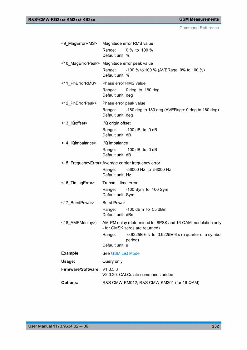
GSM MeasurementsR&S®CMW-KG2xx/-KM2xx/-KS2xx
232User Manual 1173.9634.02 ─ 06
<9_MagErrorRMS> Magnitude error RMS valueRange: 0 % to 100 %Default unit: %
<10_MagErrorPeak> Magnitude error peak valueRange: -100 % to 100 % (AVERage: 0% to 100 %)Default unit: %
<11_PhErrorRMS> Phase error RMS valueRange: 0 deg to 180 degDefault unit: deg
<12_PhErrorPeak> Phase error peak valueRange: -180 deg to 180 deg (AVERage: 0 deg to 180 deg)Default unit: deg
<13_IQoffset> I/Q origin offsetRange: -100 dB to 0 dBDefault unit: dB
<14_IQimbalance> I/Q imbalanceRange: -100 dB to 0 dBDefault unit: dB
<15_FrequencyError> Average carrier frequency errorRange: -56000 Hz to 56000 HzDefault unit: Hz
<16_TimingError> Transmit time errorRange: -100 Sym to 100 SymDefault unit: Sym
<17_BurstPower> Burst PowerRange: -100 dBm to 55 dBmDefault unit: dBm
<18_AMPMdelay>} AM-PM delay (determined for 8PSK and 16-QAM modulation only- for GMSK zeros are returned)Range: -0.9225E-6 s to 0.9225E-6 s (a quarter of a symbol
period)Default unit: s
Example: See GSM List Mode
Usage: Query only
Firmware/Software: V1.0.5.3V2.0.20: CALCulate commands added.
Options: R&S CMW-KM012; R&S CMW-KM201 (for 16-QAM)
Command Reference
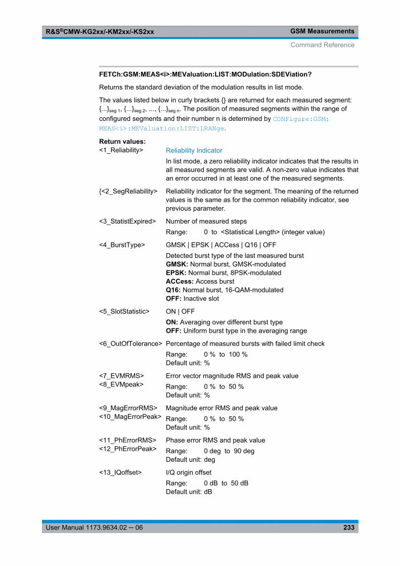
GSM MeasurementsR&S®CMW-KG2xx/-KM2xx/-KS2xx
233User Manual 1173.9634.02 ─ 06
FETCh:GSM:MEAS<i>:MEValuation:LIST:MODulation:SDEViation?
Returns the standard deviation of the modulation results in list mode.
The values listed below in curly brackets {} are returned for each measured segment:{...}seg 1, {...}seg 2, ..., {...}seg n. The position of measured segments within the range ofconfigured segments and their number n is determined by CONFigure: GSM: MEAS<i>: MEValuation: LIST: LRANge .
Return values: <1_Reliability> Reliability Indicator
In list mode, a zero reliability indicator indicates that the results inall measured segments are valid. A non-zero value indicates thatan error occurred in at least one of the measured segments.
{<2_SegReliability> Reliability indicator for the segment. The meaning of the returnedvalues is the same as for the common reliability indicator, seeprevious parameter.
<3_StatistExpired> Number of measured stepsRange: 0 to <Statistical Length> (integer value)
<4_BurstType> GMSK | EPSK | ACCess | Q16 | OFFDetected burst type of the last measured burstGMSK: Normal burst, GMSK-modulatedEPSK: Normal burst, 8PSK-modulatedACCess: Access burstQ16: Normal burst, 16-QAM-modulatedOFF: Inactive slot
<5_SlotStatistic> ON | OFFON: Averaging over different burst typeOFF: Uniform burst type in the averaging range
<6_OutOfTolerance> Percentage of measured bursts with failed limit checkRange: 0 % to 100 %Default unit: %
<7_EVMRMS><8_EVMpeak>
Error vector magnitude RMS and peak valueRange: 0 % to 50 %Default unit: %
<9_MagErrorRMS><10_MagErrorPeak>
Magnitude error RMS and peak valueRange: 0 % to 50 %Default unit: %
<11_PhErrorRMS><12_PhErrorPeak>
Phase error RMS and peak valueRange: 0 deg to 90 degDefault unit: deg
<13_IQoffset> I/Q origin offsetRange: 0 dB to 50 dBDefault unit: dB
Command Reference
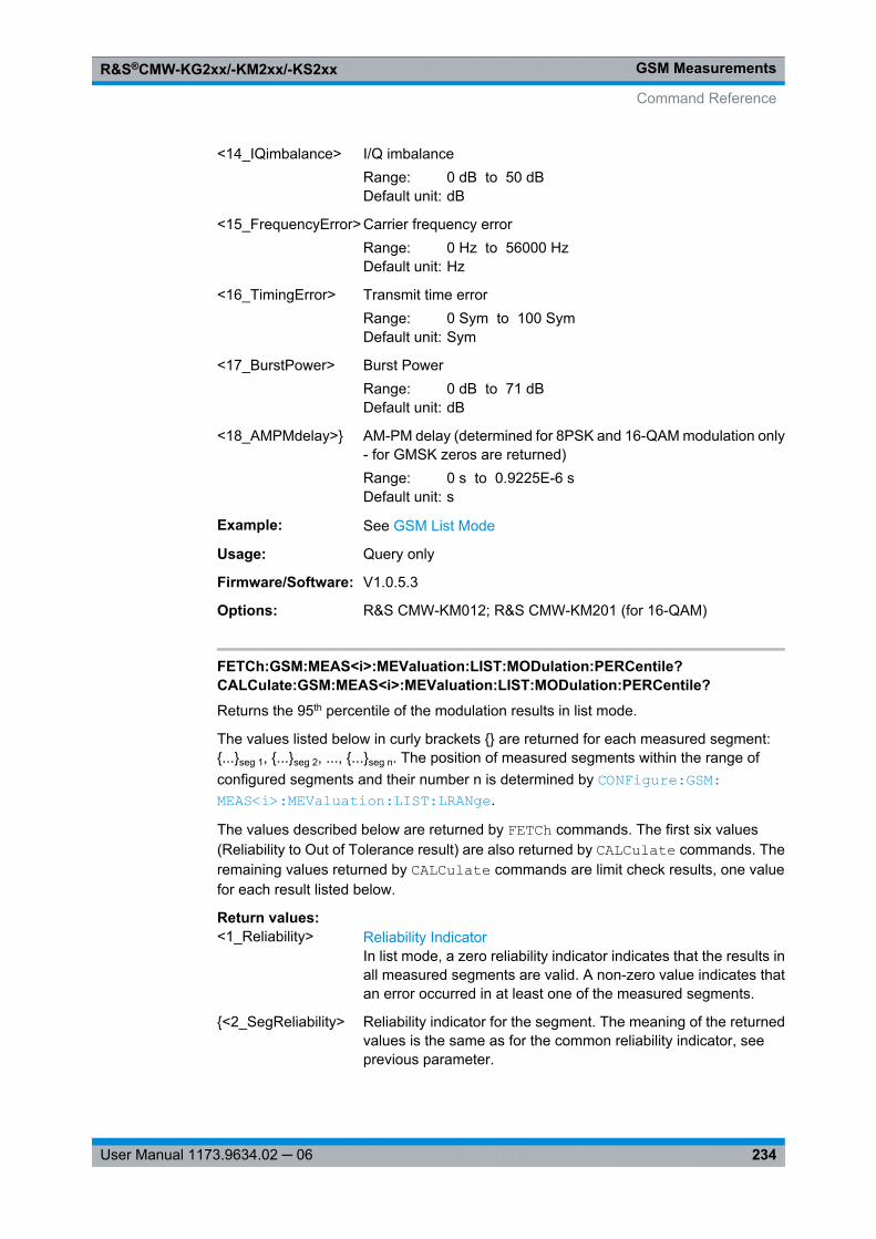
GSM MeasurementsR&S®CMW-KG2xx/-KM2xx/-KS2xx
234User Manual 1173.9634.02 ─ 06
<14_IQimbalance> I/Q imbalanceRange: 0 dB to 50 dBDefault unit: dB
<15_FrequencyError> Carrier frequency errorRange: 0 Hz to 56000 HzDefault unit: Hz
<16_TimingError> Transmit time errorRange: 0 Sym to 100 SymDefault unit: Sym
<17_BurstPower> Burst PowerRange: 0 dB to 71 dBDefault unit: dB
<18_AMPMdelay>} AM-PM delay (determined for 8PSK and 16-QAM modulation only- for GMSK zeros are returned)Range: 0 s to 0.9225E-6 sDefault unit: s
Example: See GSM List Mode
Usage: Query only
Firmware/Software: V1.0.5.3
Options: R&S CMW-KM012; R&S CMW-KM201 (for 16-QAM)
FETCh:GSM:MEAS<i>:MEValuation:LIST:MODulation:PERCentile?CALCulate:GSM:MEAS<i>:MEValuation:LIST:MODulation:PERCentile?Returns the 95th percentile of the modulation results in list mode.
The values listed below in curly brackets {} are returned for each measured segment:{...}seg 1, {...}seg 2, ..., {...}seg n. The position of measured segments within the range ofconfigured segments and their number n is determined by CONFigure: GSM: MEAS<i>: MEValuation: LIST: LRANge .
The values described below are returned by FETCh commands. The first six values(Reliability to Out of Tolerance result) are also returned by CALCulate commands. Theremaining values returned by CALCulate commands are limit check results, one valuefor each result listed below.
Return values: <1_Reliability> Reliability Indicator
In list mode, a zero reliability indicator indicates that the results inall measured segments are valid. A non-zero value indicates thatan error occurred in at least one of the measured segments.
{<2_SegReliability> Reliability indicator for the segment. The meaning of the returnedvalues is the same as for the common reliability indicator, seeprevious parameter.
Command Reference

GSM MeasurementsR&S®CMW-KG2xx/-KM2xx/-KS2xx
235User Manual 1173.9634.02 ─ 06
<3_StatistExpired> Number of measured stepsRange: 0 to <Statistical Length> (integer value)
<4_BurstType> GMSK | EPSK | ACCess | Q16 | OFFDetected burst type of the last measured burstGMSK: Normal burst, GMSK-modulatedEPSK: Normal burst, 8PSK-modulatedACCess: Access burstQ16: Normal burst, 16-QAM-modulatedOFF: Inactive slot
<5_SlotStatistic> ON | OFFON: Averaging over different burst typeOFF: Uniform burst type in the averaging range
<6_OutOfTolerance> Percentage of measured bursts with failed limit checkRange: 0 % to 100 %Default unit: %
<7_EVM> Error vector magnitude percentileRange: 0 % to 100 %Default unit: %
<8_MagnitudeError> Magnitude error percentileRange: 0 % to 100 %Default unit: %
<9_PhaseError>} Phase error percentileRange: 0 deg to 180 degDefault unit: deg
Example: See GSM List Mode
Usage: Query only
Firmware/Software: V1.0.5.3V2.0.20: CALCulate command added.
Options: R&S CMW-KM012; R&S CMW-KM201 (for 16-QAM)
FETCh:GSM:MEAS<i>:MEValuation:LIST:BER?
Returns the BER results in list mode.
The values listed below in curly brackets {} are returned for each measured segment:{...}seg 1, {...}seg 2, ..., {...}seg n. The position of measured segments within the range ofconfigured segments and their number n is determined by CONFigure: GSM: MEAS<i>: MEValuation: LIST: LRANge .
Command Reference
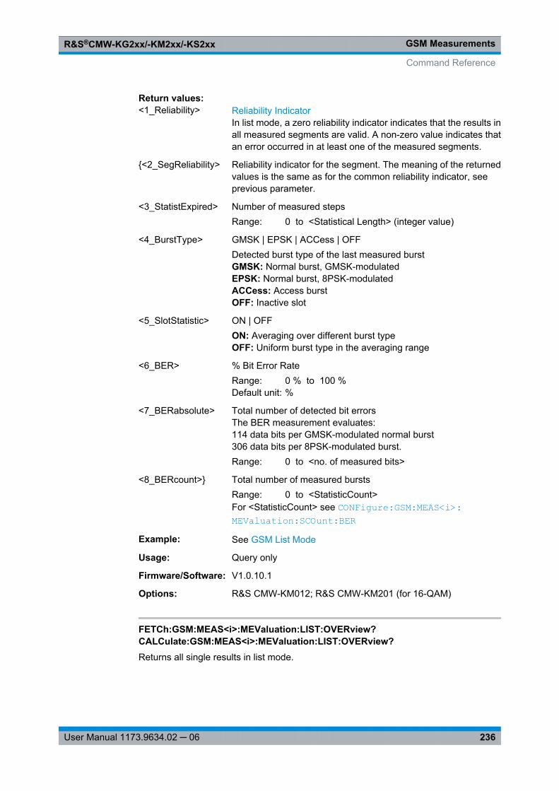
GSM MeasurementsR&S®CMW-KG2xx/-KM2xx/-KS2xx
236User Manual 1173.9634.02 ─ 06
Return values: <1_Reliability> Reliability Indicator
In list mode, a zero reliability indicator indicates that the results inall measured segments are valid. A non-zero value indicates thatan error occurred in at least one of the measured segments.
{<2_SegReliability> Reliability indicator for the segment. The meaning of the returnedvalues is the same as for the common reliability indicator, seeprevious parameter.
<3_StatistExpired> Number of measured stepsRange: 0 to <Statistical Length> (integer value)
<4_BurstType> GMSK | EPSK | ACCess | OFFDetected burst type of the last measured burstGMSK: Normal burst, GMSK-modulatedEPSK: Normal burst, 8PSK-modulatedACCess: Access burstOFF: Inactive slot
<5_SlotStatistic> ON | OFFON: Averaging over different burst typeOFF: Uniform burst type in the averaging range
<6_BER> % Bit Error RateRange: 0 % to 100 %Default unit: %
<7_BERabsolute> Total number of detected bit errorsThe BER measurement evaluates:114 data bits per GMSK-modulated normal burst306 data bits per 8PSK-modulated burst.Range: 0 to <no. of measured bits>
<8_BERcount>} Total number of measured burstsRange: 0 to <StatisticCount>For <StatisticCount> see CONFigure: GSM: MEAS<i>: MEValuation: SCOunt: BER
Example: See GSM List Mode
Usage: Query only
Firmware/Software: V1.0.10.1
Options: R&S CMW-KM012; R&S CMW-KM201 (for 16-QAM)
FETCh:GSM:MEAS<i>:MEValuation:LIST:OVERview?CALCulate:GSM:MEAS<i>:MEValuation:LIST:OVERview?Returns all single results in list mode.
Command Reference
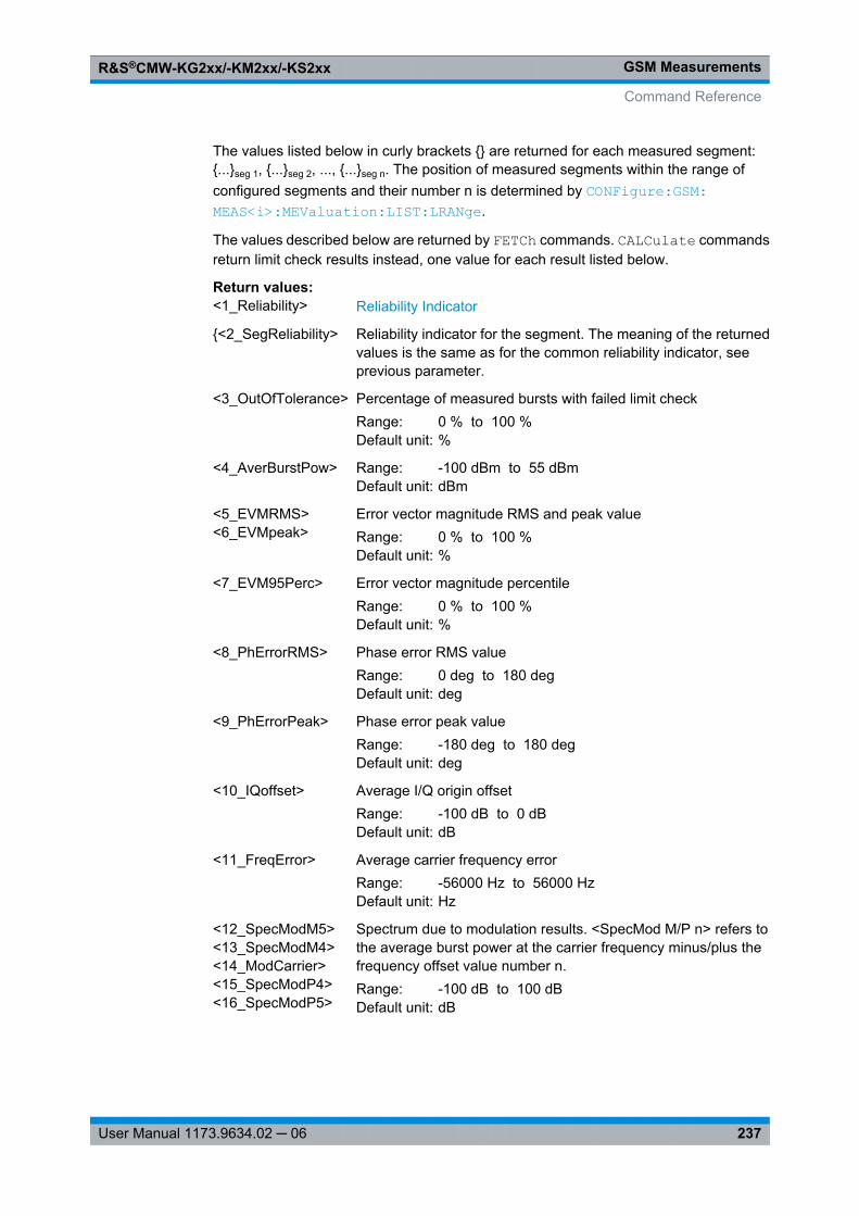
GSM MeasurementsR&S®CMW-KG2xx/-KM2xx/-KS2xx
237User Manual 1173.9634.02 ─ 06
The values listed below in curly brackets {} are returned for each measured segment:{...}seg 1, {...}seg 2, ..., {...}seg n. The position of measured segments within the range ofconfigured segments and their number n is determined by CONFigure: GSM: MEAS<i>: MEValuation: LIST: LRANge .
The values described below are returned by FETCh commands. CALCulate commandsreturn limit check results instead, one value for each result listed below.
Return values: <1_Reliability> Reliability Indicator
{<2_SegReliability> Reliability indicator for the segment. The meaning of the returnedvalues is the same as for the common reliability indicator, seeprevious parameter.
<3_OutOfTolerance> Percentage of measured bursts with failed limit checkRange: 0 % to 100 %Default unit: %
<4_AverBurstPow> Range: -100 dBm to 55 dBmDefault unit: dBm
<5_EVMRMS><6_EVMpeak>
Error vector magnitude RMS and peak valueRange: 0 % to 100 %Default unit: %
<7_EVM95Perc> Error vector magnitude percentileRange: 0 % to 100 %Default unit: %
<8_PhErrorRMS> Phase error RMS valueRange: 0 deg to 180 degDefault unit: deg
<9_PhErrorPeak> Phase error peak valueRange: -180 deg to 180 degDefault unit: deg
<10_IQoffset> Average I/Q origin offsetRange: -100 dB to 0 dBDefault unit: dB
<11_FreqError> Average carrier frequency errorRange: -56000 Hz to 56000 HzDefault unit: Hz
<12_SpecModM5><13_SpecModM4><14_ModCarrier><15_SpecModP4><16_SpecModP5>
Spectrum due to modulation results. <SpecMod M/P n> refers tothe average burst power at the carrier frequency minus/plus thefrequency offset value number n.Range: -100 dB to 100 dBDefault unit: dB
Command Reference
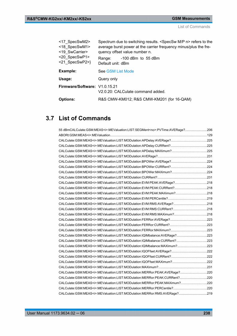
GSM MeasurementsR&S®CMW-KG2xx/-KM2xx/-KS2xx
238User Manual 1173.9634.02 ─ 06
<17_SpecSwM2><18_SpecSwM1><19_SwCarrier><20_SpecSwP1><21_SpecSwP2>}
Spectrum due to switching results. <SpecSw M/P n> refers to theaverage burst power at the carrier frequency minus/plus the fre-quency offset value number n.Range: -100 dBm to 55 dBmDefault unit: dBm
Example: See GSM List Mode
Usage: Query only
Firmware/Software: V1.0.15.21V2.0.20: CALCulate command added.
Options: R&S CMW-KM012; R&S CMW-KM201 (for 16-QAM)
3.7 List of Commands
55 dBmCALCulate: GSM:MEAS<i>:MEValuation: LIST:SEGMent<no>: PVTime:AVERage? ........................206ABORt:GSM:MEAS<i>:MEValuation .............................................................................................................129CALCulate: GSM:MEAS<i>:MEValuation: LIST:MODulation: APDelay: AVERage? ........................................225CALCulate: GSM:MEAS<i>:MEValuation: LIST:MODulation: APDelay: CURRent? .........................................225CALCulate: GSM:MEAS<i>:MEValuation: LIST:MODulation: APDelay: MAXimum? ........................................225CALCulate: GSM:MEAS<i>:MEValuation: LIST:MODulation: AVERage? .......................................................231CALCulate: GSM:MEAS<i>:MEValuation: LIST:MODulation: BPOWer:AVERage? ........................................224CALCulate: GSM:MEAS<i>:MEValuation: LIST:MODulation: BPOWer:CURRent? .........................................224CALCulate: GSM:MEAS<i>:MEValuation: LIST:MODulation: BPOWer:MAXimum? .......................................224CALCulate: GSM:MEAS<i>:MEValuation: LIST:MODulation: CURRent? ........................................................231CALCulate: GSM:MEAS<i>:MEValuation: LIST:MODulation: EVM:PEAK:AVERage? ....................................218CALCulate: GSM:MEAS<i>:MEValuation: LIST:MODulation: EVM:PEAK:CURRent? ....................................218CALCulate: GSM:MEAS<i>:MEValuation: LIST:MODulation: EVM:PEAK:MAXimum? ...................................218CALCulate: GSM:MEAS<i>:MEValuation: LIST:MODulation: EVM:PERCentile? ............................................219CALCulate: GSM:MEAS<i>:MEValuation: LIST:MODulation: EVM:RMS:AVERage? ......................................218CALCulate: GSM:MEAS<i>:MEValuation: LIST:MODulation: EVM:RMS:CURRent? ......................................218CALCulate: GSM:MEAS<i>:MEValuation: LIST:MODulation: EVM:RMS:MAXimum? .....................................218CALCulate: GSM:MEAS<i>:MEValuation: LIST:MODulation: FERRor: AVERage? .........................................223CALCulate: GSM:MEAS<i>:MEValuation: LIST:MODulation: FERRor: CURRent? ..........................................223CALCulate: GSM:MEAS<i>:MEValuation: LIST:MODulation: FERRor: MAXimum? .........................................223CALCulate: GSM:MEAS<i>:MEValuation: LIST:MODulation: IQIMbalance: AVERage? ..................................223CALCulate: GSM:MEAS<i>:MEValuation: LIST:MODulation: IQIMbalance: CURRent? ..................................223CALCulate: GSM:MEAS<i>:MEValuation: LIST:MODulation: IQIMbalance: MAXimum? .................................223CALCulate: GSM:MEAS<i>:MEValuation: LIST:MODulation: IQOFfset:AVERage? ........................................222CALCulate: GSM:MEAS<i>:MEValuation: LIST:MODulation: IQOFfset:CURRent? ........................................222CALCulate: GSM:MEAS<i>:MEValuation: LIST:MODulation: IQOFfset:MAXimum? .......................................222CALCulate: GSM:MEAS<i>:MEValuation: LIST:MODulation: MAXimum? .......................................................231CALCulate: GSM:MEAS<i>:MEValuation: LIST:MODulation: MERRor: PEAK:AVERage? ..............................220CALCulate: GSM:MEAS<i>:MEValuation: LIST:MODulation: MERRor: PEAK:CURRent? ..............................220CALCulate: GSM:MEAS<i>:MEValuation: LIST:MODulation: MERRor: PEAK:MAXimum? .............................220CALCulate: GSM:MEAS<i>:MEValuation: LIST:MODulation: MERRor: PERCentile? ......................................220CALCulate: GSM:MEAS<i>:MEValuation: LIST:MODulation: MERRor: RMS:AVERage? ................................219
List of Commands
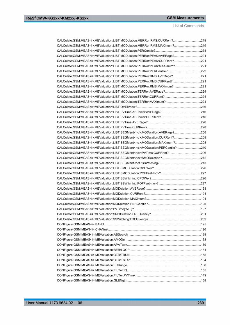
GSM MeasurementsR&S®CMW-KG2xx/-KM2xx/-KS2xx
239User Manual 1173.9634.02 ─ 06
CALCulate: GSM:MEAS<i>:MEValuation: LIST:MODulation: MERRor: RMS:CURRent? ................................219CALCulate: GSM:MEAS<i>:MEValuation: LIST:MODulation: MERRor: RMS:MAXimum? ...............................219CALCulate: GSM:MEAS<i>:MEValuation: LIST:MODulation: PERCentile? .....................................................234CALCulate: GSM:MEAS<i>:MEValuation: LIST:MODulation: PERRor: PEAK:AVERage? ...............................221CALCulate: GSM:MEAS<i>:MEValuation: LIST:MODulation: PERRor: PEAK:CURRent? ...............................221CALCulate: GSM:MEAS<i>:MEValuation: LIST:MODulation: PERRor: PEAK:MAXimum? ..............................221CALCulate: GSM:MEAS<i>:MEValuation: LIST:MODulation: PERRor: PERCentile? ......................................222CALCulate: GSM:MEAS<i>:MEValuation: LIST:MODulation: PERRor: RMS:AVERage? ................................221CALCulate: GSM:MEAS<i>:MEValuation: LIST:MODulation: PERRor: RMS:CURRent? .................................221CALCulate: GSM:MEAS<i>:MEValuation: LIST:MODulation: PERRor: RMS:MAXimum? ...............................221CALCulate: GSM:MEAS<i>:MEValuation: LIST:MODulation: TERRor: AVERage? .........................................224CALCulate: GSM:MEAS<i>:MEValuation: LIST:MODulation: TERRor: CURRent? ..........................................224CALCulate: GSM:MEAS<i>:MEValuation: LIST:MODulation: TERRor: MAXimum? .........................................224CALCulate: GSM:MEAS<i>:MEValuation: LIST:OVERview? ..........................................................................236CALCulate: GSM:MEAS<i>:MEValuation: LIST:PVTime:ABPower: AVERage? ..............................................216CALCulate: GSM:MEAS<i>:MEValuation: LIST:PVTime:ABPower: CURRent? ..............................................216CALCulate: GSM:MEAS<i>:MEValuation: LIST:PVTime:AVERage? ..............................................................228CALCulate: GSM:MEAS<i>:MEValuation: LIST:PVTime:CURRent? ..............................................................228CALCulate: GSM:MEAS<i>:MEValuation: LIST:SEGMent<no>: MODulation: AVERage? ...............................208CALCulate: GSM:MEAS<i>:MEValuation: LIST:SEGMent<no>: MODulation: CURRent? ...............................208CALCulate: GSM:MEAS<i>:MEValuation: LIST:SEGMent<no>: MODulation: MAXimum? ..............................208CALCulate: GSM:MEAS<i>:MEValuation: LIST:SEGMent<no>: MODulation: PERCentile? ............................210CALCulate: GSM:MEAS<i>:MEValuation: LIST:SEGMent<no>: PVTime:CURRent? .....................................206CALCulate: GSM:MEAS<i>:MEValuation: LIST:SEGMent<no>: SMODulation? .............................................212CALCulate: GSM:MEAS<i>:MEValuation: LIST:SEGMent<no>: SSWitching? ................................................213CALCulate: GSM:MEAS<i>:MEValuation: LIST:SMODulation: CPOWer? ......................................................226CALCulate: GSM:MEAS<i>:MEValuation: LIST:SMODulation: POFFset<no>?..............................................227CALCulate: GSM:MEAS<i>:MEValuation: LIST:SSWitching: CPOWer? .........................................................226CALCulate: GSM:MEAS<i>:MEValuation: LIST:SSWitching: POFFset<no>?.................................................227CALCulate: GSM:MEAS<i>:MEValuation: MODulation: AVERage? ................................................................193CALCulate: GSM:MEAS<i>:MEValuation: MODulation: CURRent? ................................................................191CALCulate: GSM:MEAS<i>:MEValuation: MODulation: MAXimum? ...............................................................191CALCulate: GSM:MEAS<i>:MEValuation: MODulation: PERCentile? .............................................................195CALCulate: GSM:MEAS<i>:MEValuation: PVTime[:ALL]? ..............................................................................197CALCulate: GSM:MEAS<i>:MEValuation: SMODulation: FREQuency? ..........................................................201CALCulate: GSM:MEAS<i>:MEValuation: SSWitching: FREQuency? .............................................................202CONFigure: GSM:MEAS<i>:BAND ................................................................................................................125CONFigure: GSM:MEAS<i>:CHANnel ...........................................................................................................126CONFigure: GSM:MEAS<i>:MEValuation: ABSearch .....................................................................................139CONFigure: GSM:MEAS<i>:MEValuation: AMODe ........................................................................................158CONFigure: GSM:MEAS<i>:MEValuation: APATtern.....................................................................................159CONFigure: GSM:MEAS<i>:MEValuation: BER:LOOP...................................................................................154CONFigure: GSM:MEAS<i>:MEValuation: BER:TRUN ...................................................................................155CONFigure: GSM:MEAS<i>:MEValuation: BER:TSTart..................................................................................154CONFigure: GSM:MEAS<i>:MEValuation: FCRange ......................................................................................138CONFigure: GSM:MEAS<i>:MEValuation: FILTer:IQ......................................................................................155CONFigure: GSM:MEAS<i>:MEValuation: FILTer:PVTime .............................................................................149CONFigure: GSM:MEAS<i>:MEValuation: GLENgth ......................................................................................158
List of Commands
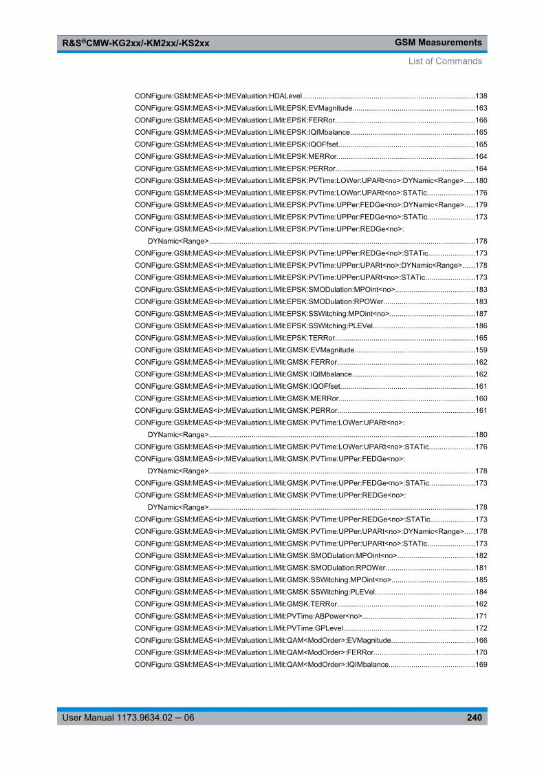
GSM MeasurementsR&S®CMW-KG2xx/-KM2xx/-KS2xx
240User Manual 1173.9634.02 ─ 06
CONFigure: GSM:MEAS<i>:MEValuation: HDALevel .....................................................................................138CONFigure: GSM:MEAS<i>:MEValuation: LIMit:EPSK:EVMagnitude ............................................................163CONFigure: GSM:MEAS<i>:MEValuation: LIMit:EPSK:FERRor .....................................................................166CONFigure: GSM:MEAS<i>:MEValuation: LIMit:EPSK:IQIMbalance .............................................................165CONFigure: GSM:MEAS<i>:MEValuation: LIMit:EPSK:IQOFfset...................................................................165CONFigure: GSM:MEAS<i>:MEValuation: LIMit:EPSK:MERRor ....................................................................164CONFigure: GSM:MEAS<i>:MEValuation: LIMit:EPSK:PERRor ....................................................................164CONFigure: GSM:MEAS<i>:MEValuation: LIMit:EPSK:PVTime:LOWer:UPARt<no>: DYNamic<Range> .....180CONFigure: GSM:MEAS<i>:MEValuation: LIMit:EPSK:PVTime:LOWer:UPARt<no>: STATic.......................176CONFigure: GSM:MEAS<i>:MEValuation: LIMit:EPSK:PVTime:UPPer: FEDGe<no>: DYNamic<Range> .....179CONFigure: GSM:MEAS<i>:MEValuation: LIMit:EPSK:PVTime:UPPer: FEDGe<no>: STATic.......................173CONFigure: GSM:MEAS<i>:MEValuation: LIMit:EPSK:PVTime:UPPer: REDGe<no>:
DYNamic<Range> ...................................................................................................................................178CONFigure: GSM:MEAS<i>:MEValuation: LIMit:EPSK:PVTime:UPPer: REDGe<no>: STATic.......................173CONFigure: GSM:MEAS<i>:MEValuation: LIMit:EPSK:PVTime:UPPer: UPARt<no>: DYNamic<Range> ......178CONFigure: GSM:MEAS<i>:MEValuation: LIMit:EPSK:PVTime:UPPer: UPARt<no>: STATic........................173CONFigure: GSM:MEAS<i>:MEValuation: LIMit:EPSK:SMODulation: MPOint<no> .......................................183CONFigure: GSM:MEAS<i>:MEValuation: LIMit:EPSK:SMODulation: RPOWer.............................................183CONFigure: GSM:MEAS<i>:MEValuation: LIMit:EPSK:SSWitching: MPOint<no> ..........................................187CONFigure: GSM:MEAS<i>:MEValuation: LIMit:EPSK:SSWitching: PLEVel ..................................................186CONFigure: GSM:MEAS<i>:MEValuation: LIMit:EPSK:TERRor .....................................................................165CONFigure: GSM:MEAS<i>:MEValuation: LIMit:GMSK:EVMagnitude ...........................................................159CONFigure: GSM:MEAS<i>:MEValuation: LIMit:GMSK:FERRor ....................................................................162CONFigure: GSM:MEAS<i>:MEValuation: LIMit:GMSK:IQIMbalance ............................................................162CONFigure: GSM:MEAS<i>:MEValuation: LIMit:GMSK:IQOFfset..................................................................161CONFigure: GSM:MEAS<i>:MEValuation: LIMit:GMSK:MERRor ...................................................................160CONFigure: GSM:MEAS<i>:MEValuation: LIMit:GMSK:PERRor ...................................................................161CONFigure: GSM:MEAS<i>:MEValuation: LIMit:GMSK:PVTime:LOWer:UPARt<no>:
DYNamic<Range> ...................................................................................................................................180CONFigure: GSM:MEAS<i>:MEValuation: LIMit:GMSK:PVTime:LOWer:UPARt<no>: STATic......................176CONFigure: GSM:MEAS<i>:MEValuation: LIMit:GMSK:PVTime:UPPer: FEDGe<no>:
DYNamic<Range> ...................................................................................................................................178CONFigure: GSM:MEAS<i>:MEValuation: LIMit:GMSK:PVTime:UPPer: FEDGe<no>: STATic......................173CONFigure: GSM:MEAS<i>:MEValuation: LIMit:GMSK:PVTime:UPPer: REDGe<no>:
DYNamic<Range> ...................................................................................................................................178CONFigure: GSM:MEAS<i>:MEValuation: LIMit:GMSK:PVTime:UPPer: REDGe<no>: STATic......................173CONFigure: GSM:MEAS<i>:MEValuation: LIMit:GMSK:PVTime:UPPer: UPARt<no>: DYNamic<Range> .....178CONFigure: GSM:MEAS<i>:MEValuation: LIMit:GMSK:PVTime:UPPer: UPARt<no>: STATic.......................173CONFigure: GSM:MEAS<i>:MEValuation: LIMit:GMSK:SMODulation: MPOint<no> ......................................182CONFigure: GSM:MEAS<i>:MEValuation: LIMit:GMSK:SMODulation: RPOWer............................................181CONFigure: GSM:MEAS<i>:MEValuation: LIMit:GMSK:SSWitching: MPOint<no> .........................................185CONFigure: GSM:MEAS<i>:MEValuation: LIMit:GMSK:SSWitching: PLEVel .................................................184CONFigure: GSM:MEAS<i>:MEValuation: LIMit:GMSK:TERRor ....................................................................162CONFigure: GSM:MEAS<i>:MEValuation: LIMit:PVTime:ABPower<no> .......................................................171CONFigure: GSM:MEAS<i>:MEValuation: LIMit:PVTime:GPLevel .................................................................172CONFigure: GSM:MEAS<i>:MEValuation: LIMit:QAM<ModOrder>: EVMagnitude .........................................166CONFigure: GSM:MEAS<i>:MEValuation: LIMit:QAM<ModOrder>: FERRor ..................................................170CONFigure: GSM:MEAS<i>:MEValuation: LIMit:QAM<ModOrder>: IQIMbalance ..........................................169
List of Commands
GSM MeasurementsR&S®CMW-KG2xx/-KM2xx/-KS2xx
241User Manual 1173.9634.02 ─ 06
CONFigure: GSM:MEAS<i>:MEValuation: LIMit:QAM<ModOrder>: IQOFfset................................................168CONFigure: GSM:MEAS<i>:MEValuation: LIMit:QAM<ModOrder>: MERRor .................................................167CONFigure: GSM:MEAS<i>:MEValuation: LIMit:QAM<ModOrder>: PERRor .................................................168CONFigure: GSM:MEAS<i>:MEValuation: LIMit:QAM<ModOrder>: PVTime:LOWer:UPARt<no>:
DYNamic<Range> ...................................................................................................................................180CONFigure: GSM:MEAS<i>:MEValuation: LIMit:QAM<ModOrder>: PVTime:LOWer:UPARt<no>:
STATic.....................................................................................................................................................176CONFigure: GSM:MEAS<i>:MEValuation: LIMit:QAM<ModOrder>: PVTime:UPPer: FEDGe<no>:
DYNamic<Range> ...................................................................................................................................179CONFigure: GSM:MEAS<i>:MEValuation: LIMit:QAM<ModOrder>: PVTime:UPPer: FEDGe<no>:
STATic.....................................................................................................................................................173CONFigure: GSM:MEAS<i>:MEValuation: LIMit:QAM<ModOrder>: PVTime:UPPer: REDGe<no>:
DYNamic<Range> ...................................................................................................................................178CONFigure: GSM:MEAS<i>:MEValuation: LIMit:QAM<ModOrder>: PVTime:UPPer: REDGe<no>:
STATic.....................................................................................................................................................173CONFigure: GSM:MEAS<i>:MEValuation: LIMit:QAM<ModOrder>: PVTime:UPPer: UPARt<no>:
DYNamic<Range> ...................................................................................................................................178CONFigure: GSM:MEAS<i>:MEValuation: LIMit:QAM<ModOrder>: PVTime:UPPer: UPARt<no>: STATic.....173CONFigure: GSM:MEAS<i>:MEValuation: LIMit:QAM<ModOrder>: SMODulation: MPOint<no> ....................183CONFigure: GSM:MEAS<i>:MEValuation: LIMit:QAM<ModOrder>: SMODulation: RPOWer..........................183CONFigure: GSM:MEAS<i>:MEValuation: LIMit:QAM<ModOrder>: SSWitching: MPOint<no> .......................187CONFigure: GSM:MEAS<i>:MEValuation: LIMit:QAM<ModOrder>: SSWitching: PLEVel ...............................186CONFigure: GSM:MEAS<i>:MEValuation: LIMit:QAM<ModOrder>: TERRor ..................................................169CONFigure: GSM:MEAS<i>:MEValuation: LIST.............................................................................................141CONFigure: GSM:MEAS<i>:MEValuation: LIST:IIFRames.............................................................................142CONFigure: GSM:MEAS<i>:MEValuation: LIST:LRANge ...............................................................................141CONFigure: GSM:MEAS<i>:MEValuation: LIST:OSINdex ..............................................................................141CONFigure: GSM:MEAS<i>:MEValuation: LIST:SEGMent<no>: BER ............................................................146CONFigure: GSM:MEAS<i>:MEValuation: LIST:SEGMent<no>: MODulation .................................................143CONFigure: GSM:MEAS<i>:MEValuation: LIST:SEGMent<no>: PVTime .......................................................144CONFigure: GSM:MEAS<i>:MEValuation: LIST:SEGMent<no>: SETup .........................................................147CONFigure: GSM:MEAS<i>:MEValuation: LIST:SEGMent<no>: SMODulation ..............................................145CONFigure: GSM:MEAS<i>:MEValuation: LIST:SEGMent<no>: SSWitching .................................................146CONFigure: GSM:MEAS<i>:MEValuation: LIST:SLENgth ..............................................................................143CONFigure: GSM:MEAS<i>:MEValuation: MODulation: DECode ...................................................................150CONFigure: GSM:MEAS<i>:MEValuation: MOEXception ...............................................................................137CONFigure: GSM:MEAS<i>:MEValuation: MSLots .........................................................................................137CONFigure: GSM:MEAS<i>:MEValuation: MVIew ..........................................................................................140CONFigure: GSM:MEAS<i>:MEValuation: NBQSearch ..................................................................................138CONFigure: GSM:MEAS<i>:MEValuation: PCL ..............................................................................................150CONFigure: GSM:MEAS<i>:MEValuation: PCLMode .....................................................................................149CONFigure: GSM:MEAS<i>:MEValuation: REPetition ....................................................................................134CONFigure: GSM:MEAS<i>:MEValuation: RESult: AMPM..............................................................................132CONFigure: GSM:MEAS<i>:MEValuation: RESult: BER .................................................................................132CONFigure: GSM:MEAS<i>:MEValuation: RESult: EVMagnitude ...................................................................131CONFigure: GSM:MEAS<i>:MEValuation: RESult: IQ.....................................................................................131CONFigure: GSM:MEAS<i>:MEValuation: RESult: MERRor ...........................................................................131CONFigure: GSM:MEAS<i>:MEValuation: RESult: MSCalar ...........................................................................132
List of Commands
GSM MeasurementsR&S®CMW-KG2xx/-KM2xx/-KS2xx
242User Manual 1173.9634.02 ─ 06
CONFigure: GSM:MEAS<i>:MEValuation: RESult: PERRor ............................................................................131CONFigure: GSM:MEAS<i>:MEValuation: RESult: PVTime ............................................................................131CONFigure: GSM:MEAS<i>:MEValuation: RESult: SMFRequency .................................................................131CONFigure: GSM:MEAS<i>:MEValuation: RESult: SMTime ...........................................................................131CONFigure: GSM:MEAS<i>:MEValuation: RESult: SSFRequency ..................................................................131CONFigure: GSM:MEAS<i>:MEValuation: RESult: SSTime ............................................................................131CONFigure: GSM:MEAS<i>:MEValuation: RESult[:ALL] ................................................................................132CONFigure: GSM:MEAS<i>:MEValuation: ROTation: IQ.................................................................................155CONFigure: GSM:MEAS<i>:MEValuation: RPMode .......................................................................................149CONFigure: GSM:MEAS<i>:MEValuation: SCONdition ..................................................................................137CONFigure: GSM:MEAS<i>:MEValuation: SCOunt:BER ................................................................................136CONFigure: GSM:MEAS<i>:MEValuation: SCOunt:MODulation ....................................................................135CONFigure: GSM:MEAS<i>:MEValuation: SCOunt:PVTime ..........................................................................135CONFigure: GSM:MEAS<i>:MEValuation: SCOunt:SMODulation ..................................................................135CONFigure: GSM:MEAS<i>:MEValuation: SCOunt:SSWitching .....................................................................136CONFigure: GSM:MEAS<i>:MEValuation: SMODulation: EARea ...................................................................151CONFigure: GSM:MEAS<i>:MEValuation: SMODulation: OFRequence .........................................................151CONFigure: GSM:MEAS<i>:MEValuation: SMODulation: TDFSelect ..............................................................152CONFigure: GSM:MEAS<i>:MEValuation: SSWitching: OFRequence ............................................................153CONFigure: GSM:MEAS<i>:MEValuation: SSWitching: PHMode ...................................................................153CONFigure: GSM:MEAS<i>:MEValuation: SSWitching: TDFSelect ................................................................153CONFigure: GSM:MEAS<i>:MEValuation: TOUT...........................................................................................134CONFigure: GSM:MEAS<i>:MEValuation: TSEQuence .................................................................................139CONFigure: GSM:MEAS<i>:MEValuation: VAMos:TSCSet............................................................................139CONFigure: GSM:MEAS<i>:RFSettings: EATTenuation .................................................................................124CONFigure: GSM:MEAS<i>:RFSettings: ENPower ........................................................................................127CONFigure: GSM:MEAS<i>:RFSettings: FREQuency ....................................................................................126CONFigure: GSM:MEAS<i>:RFSettings: MLOFfset........................................................................................127CONFigure: GSM:MEAS<i>:RFSettings: UMARgin ........................................................................................127FETCh:GSM:MEAS<i>:MEValuation: BER? ..................................................................................................205FETCh:GSM:MEAS<i>:MEValuation: LIST:BER:ABSolute? ..........................................................................226FETCh:GSM:MEAS<i>:MEValuation: LIST:BER:BER? .................................................................................225FETCh:GSM:MEAS<i>:MEValuation: LIST:BER:COUNt? .............................................................................226FETCh:GSM:MEAS<i>:MEValuation: LIST:BER? ..........................................................................................235FETCh:GSM:MEAS<i>:MEValuation: LIST:MODulation: APDelay: AVERage? ..............................................225FETCh:GSM:MEAS<i>:MEValuation: LIST:MODulation: APDelay: CURRent? ...............................................225FETCh:GSM:MEAS<i>:MEValuation: LIST:MODulation: APDelay: MAXimum? ..............................................225FETCh:GSM:MEAS<i>:MEValuation: LIST:MODulation: APDelay: SDEViation? ............................................225FETCh:GSM:MEAS<i>:MEValuation: LIST:MODulation: AVERage? .............................................................231FETCh:GSM:MEAS<i>:MEValuation: LIST:MODulation: BPOWer:AVERage? ..............................................224FETCh:GSM:MEAS<i>:MEValuation: LIST:MODulation: BPOWer:CURRent? ...............................................224FETCh:GSM:MEAS<i>:MEValuation: LIST:MODulation: BPOWer:MAXimum? .............................................224FETCh:GSM:MEAS<i>:MEValuation: LIST:MODulation: BPOWer:SDEViation? ............................................224FETCh:GSM:MEAS<i>:MEValuation: LIST:MODulation: CURRent? ..............................................................231FETCh:GSM:MEAS<i>:MEValuation: LIST:MODulation: EVM:PEAK:AVERage? ..........................................218FETCh:GSM:MEAS<i>:MEValuation: LIST:MODulation: EVM:PEAK:CURRent? ..........................................218FETCh:GSM:MEAS<i>:MEValuation: LIST:MODulation: EVM:PEAK:MAXimum? .........................................218FETCh:GSM:MEAS<i>:MEValuation: LIST:MODulation: EVM:PEAK:SDEViation? .......................................218
List of Commands
GSM MeasurementsR&S®CMW-KG2xx/-KM2xx/-KS2xx
243User Manual 1173.9634.02 ─ 06
FETCh:GSM:MEAS<i>:MEValuation: LIST:MODulation: EVM:PERCentile? ..................................................219FETCh:GSM:MEAS<i>:MEValuation: LIST:MODulation: EVM:RMS:AVERage? ............................................218FETCh:GSM:MEAS<i>:MEValuation: LIST:MODulation: EVM:RMS:CURRent? ............................................218FETCh:GSM:MEAS<i>:MEValuation: LIST:MODulation: EVM:RMS:MAXimum? ...........................................218FETCh:GSM:MEAS<i>:MEValuation: LIST:MODulation: EVM:RMS:SDEViation? .........................................218FETCh:GSM:MEAS<i>:MEValuation: LIST:MODulation: FERRor: AVERage? ...............................................223FETCh:GSM:MEAS<i>:MEValuation: LIST:MODulation: FERRor: CURRent? ................................................223FETCh:GSM:MEAS<i>:MEValuation: LIST:MODulation: FERRor: MAXimum? ...............................................223FETCh:GSM:MEAS<i>:MEValuation: LIST:MODulation: FERRor: SDEViation? .............................................223FETCh:GSM:MEAS<i>:MEValuation: LIST:MODulation: IQIMbalance: AVERage? ........................................223FETCh:GSM:MEAS<i>:MEValuation: LIST:MODulation: IQIMbalance: CURRent? ........................................223FETCh:GSM:MEAS<i>:MEValuation: LIST:MODulation: IQIMbalance: MAXimum? .......................................223FETCh:GSM:MEAS<i>:MEValuation: LIST:MODulation: IQIMbalance: SDEViation? .....................................223FETCh:GSM:MEAS<i>:MEValuation: LIST:MODulation: IQOFfset:AVERage? ..............................................222FETCh:GSM:MEAS<i>:MEValuation: LIST:MODulation: IQOFfset:CURRent? ..............................................222FETCh:GSM:MEAS<i>:MEValuation: LIST:MODulation: IQOFfset:MAXimum? .............................................222FETCh:GSM:MEAS<i>:MEValuation: LIST:MODulation: IQOFfset:SDEViation? ...........................................222FETCh:GSM:MEAS<i>:MEValuation: LIST:MODulation: MAXimum? .............................................................231FETCh:GSM:MEAS<i>:MEValuation: LIST:MODulation: MERRor: PEAK:AVERage? ....................................220FETCh:GSM:MEAS<i>:MEValuation: LIST:MODulation: MERRor: PEAK:CURRent? ....................................220FETCh:GSM:MEAS<i>:MEValuation: LIST:MODulation: MERRor: PEAK:MAXimum? ...................................220FETCh:GSM:MEAS<i>:MEValuation: LIST:MODulation: MERRor: PEAK:SDEViation? .................................220FETCh:GSM:MEAS<i>:MEValuation: LIST:MODulation: MERRor: PERCentile? ............................................220FETCh:GSM:MEAS<i>:MEValuation: LIST:MODulation: MERRor: RMS:AVERage? ......................................219FETCh:GSM:MEAS<i>:MEValuation: LIST:MODulation: MERRor: RMS:CURRent? ......................................219FETCh:GSM:MEAS<i>:MEValuation: LIST:MODulation: MERRor: RMS:MAXimum? .....................................219FETCh:GSM:MEAS<i>:MEValuation: LIST:MODulation: MERRor: RMS:SDEViation? ...................................219FETCh:GSM:MEAS<i>:MEValuation: LIST:MODulation: PERCentile? ...........................................................234FETCh:GSM:MEAS<i>:MEValuation: LIST:MODulation: PERRor: PEAK:AVERage? .....................................221FETCh:GSM:MEAS<i>:MEValuation: LIST:MODulation: PERRor: PEAK:CURRent? .....................................221FETCh:GSM:MEAS<i>:MEValuation: LIST:MODulation: PERRor: PEAK:MAXimum? ....................................221FETCh:GSM:MEAS<i>:MEValuation: LIST:MODulation: PERRor: PEAK:SDEViation? ..................................221FETCh:GSM:MEAS<i>:MEValuation: LIST:MODulation: PERRor: PERCentile? ............................................222FETCh:GSM:MEAS<i>:MEValuation: LIST:MODulation: PERRor: RMS:AVERage? ......................................221FETCh:GSM:MEAS<i>:MEValuation: LIST:MODulation: PERRor: RMS:CURRent? .......................................221FETCh:GSM:MEAS<i>:MEValuation: LIST:MODulation: PERRor: RMS:MAXimum? .....................................221FETCh:GSM:MEAS<i>:MEValuation: LIST:MODulation: PERRor: RMS:SDEViation? ....................................221FETCh:GSM:MEAS<i>:MEValuation: LIST:MODulation: SDEViation? ...........................................................233FETCh:GSM:MEAS<i>:MEValuation: LIST:MODulation: TERRor: AVERage? ...............................................224FETCh:GSM:MEAS<i>:MEValuation: LIST:MODulation: TERRor: CURRent? ................................................224FETCh:GSM:MEAS<i>:MEValuation: LIST:MODulation: TERRor: MAXimum? ...............................................224FETCh:GSM:MEAS<i>:MEValuation: LIST:MODulation: TERRor: SDEViation? .............................................224FETCh:GSM:MEAS<i>:MEValuation: LIST:OVERview? ................................................................................236FETCh:GSM:MEAS<i>:MEValuation: LIST:PVTime:ABPower: AVERage? ....................................................216FETCh:GSM:MEAS<i>:MEValuation: LIST:PVTime:ABPower: CURRent? ....................................................216FETCh:GSM:MEAS<i>:MEValuation: LIST:PVTime:AVERage? ....................................................................228FETCh:GSM:MEAS<i>:MEValuation: LIST:PVTime:CURRent: SVECtor? .....................................................230FETCh:GSM:MEAS<i>:MEValuation: LIST:PVTime:CURRent? ....................................................................228
List of Commands
GSM MeasurementsR&S®CMW-KG2xx/-KM2xx/-KS2xx
244User Manual 1173.9634.02 ─ 06
FETCh:GSM:MEAS<i>:MEValuation: LIST:PVTime:SVECtor:SUBVector<no>: AVERage? ..........................217FETCh:GSM:MEAS<i>:MEValuation: LIST:PVTime:SVECtor:SUBVector<no>: CURRent? ..........................217FETCh:GSM:MEAS<i>:MEValuation: LIST:PVTime:SVECtor:SUBVector<no>: MAXimum? .........................217FETCh:GSM:MEAS<i>:MEValuation: LIST:PVTime:SVECtor:SUBVector<no>: MINimum? ..........................217FETCh:GSM:MEAS<i>:MEValuation: LIST:PVTime:SVECtor:UMAXimum: AVERage? ................................216FETCh:GSM:MEAS<i>:MEValuation: LIST:PVTime:SVECtor:UMAXimum: CURRent? .................................216FETCh:GSM:MEAS<i>:MEValuation: LIST:PVTime:SVECtor:UMAXimum: MAXimum? ................................216FETCh:GSM:MEAS<i>:MEValuation: LIST:PVTime:SVECtor:UMAXimum: MINimum? .................................216FETCh:GSM:MEAS<i>:MEValuation: LIST:PVTime:SVECtor:UMINimum: AVERage? ..................................217FETCh:GSM:MEAS<i>:MEValuation: LIST:PVTime:SVECtor:UMINimum: CURRent? ..................................217FETCh:GSM:MEAS<i>:MEValuation: LIST:PVTime:SVECtor:UMINimum: MAXimum? .................................217FETCh:GSM:MEAS<i>:MEValuation: LIST:PVTime:SVECtor:UMINimum: MINimum? ..................................217FETCh:GSM:MEAS<i>:MEValuation: LIST:SEGMent<no>: BER? .................................................................214FETCh:GSM:MEAS<i>:MEValuation: LIST:SEGMent<no>: MODulation: AVERage? .....................................208FETCh:GSM:MEAS<i>:MEValuation: LIST:SEGMent<no>: MODulation: CURRent? .....................................208FETCh:GSM:MEAS<i>:MEValuation: LIST:SEGMent<no>: MODulation: MAXimum? ....................................208FETCh:GSM:MEAS<i>:MEValuation: LIST:SEGMent<no>: MODulation: PERCentile? ..................................210FETCh:GSM:MEAS<i>:MEValuation: LIST:SEGMent<no>: MODulation: SDEViation? ..................................208FETCh:GSM:MEAS<i>:MEValuation: LIST:SEGMent<no>: PVTime:AVERage: SVECtor? ............................207FETCh:GSM:MEAS<i>:MEValuation: LIST:SEGMent<no>: PVTime:AVERage? ...........................................206FETCh:GSM:MEAS<i>:MEValuation: LIST:SEGMent<no>: PVTime:CURRent: SVECtor? ............................207FETCh:GSM:MEAS<i>:MEValuation: LIST:SEGMent<no>: PVTime:CURRent? ...........................................206FETCh:GSM:MEAS<i>:MEValuation: LIST:SEGMent<no>: PVTime:MAXimum: SVECtor? ...........................207FETCh:GSM:MEAS<i>:MEValuation: LIST:SEGMent<no>: PVTime:MINimum: SVECtor? ............................207FETCh:GSM:MEAS<i>:MEValuation: LIST:SEGMent<no>: SMODulation? ...................................................212FETCh:GSM:MEAS<i>:MEValuation: LIST:SEGMent<no>: SSWitching? ......................................................213FETCh:GSM:MEAS<i>:MEValuation: LIST:SMODulation: CPOWer? ............................................................226FETCh:GSM:MEAS<i>:MEValuation: LIST:SMODulation: POFFset<no>?....................................................227FETCh:GSM:MEAS<i>:MEValuation: LIST:SRELiability? ..............................................................................215FETCh:GSM:MEAS<i>:MEValuation: LIST:SSWitching: CPOWer? ...............................................................226FETCh:GSM:MEAS<i>:MEValuation: LIST:SSWitching: POFFset<no>?.......................................................227FETCh:GSM:MEAS<i>:MEValuation: MODulation: AVERage? ......................................................................193FETCh:GSM:MEAS<i>:MEValuation: MODulation: CURRent? ......................................................................191FETCh:GSM:MEAS<i>:MEValuation: MODulation: DBITs?............................................................................196FETCh:GSM:MEAS<i>:MEValuation: MODulation: MAXimum? .....................................................................191FETCh:GSM:MEAS<i>:MEValuation: MODulation: PERCentile? ...................................................................195FETCh:GSM:MEAS<i>:MEValuation: MODulation: SDEViation? ...................................................................194FETCh:GSM:MEAS<i>:MEValuation: MVTHroughput? .................................................................................188FETCh:GSM:MEAS<i>:MEValuation: PVTime:AVERage: SVECtor? .............................................................198FETCh:GSM:MEAS<i>:MEValuation: PVTime:BTYPe? .................................................................................199FETCh:GSM:MEAS<i>:MEValuation: PVTime:CURRent: SVECtor? ..............................................................198FETCh:GSM:MEAS<i>:MEValuation: PVTime:MAXimum: SVECtor? ............................................................198FETCh:GSM:MEAS<i>:MEValuation: PVTime:MINimum: SVECtor? ..............................................................198FETCh:GSM:MEAS<i>:MEValuation: PVTime:RSTiming? ............................................................................199FETCh:GSM:MEAS<i>:MEValuation: PVTime:TSC? .....................................................................................200FETCh:GSM:MEAS<i>:MEValuation: PVTime[:ALL]? ....................................................................................197FETCh:GSM:MEAS<i>:MEValuation: SMODulation: FREQuency? ................................................................201FETCh:GSM:MEAS<i>:MEValuation: SMODulation? ....................................................................................202
List of Commands
GSM MeasurementsR&S®CMW-KG2xx/-KM2xx/-KS2xx
245User Manual 1173.9634.02 ─ 06
FETCh:GSM:MEAS<i>:MEValuation: SSWitching: FREQuency? ...................................................................202FETCh:GSM:MEAS<i>:MEValuation: SSWitching? .......................................................................................203FETCh:GSM:MEAS<i>:MEValuation: STATe:ALL? .......................................................................................130FETCh:GSM:MEAS<i>:MEValuation: STATe?...............................................................................................129FETCh:GSM:MEAS<i>:MEValuation: TRACe: EVMagnitude: AVERage? .......................................................189FETCh:GSM:MEAS<i>:MEValuation: TRACe: EVMagnitude: CURRent? .......................................................189FETCh:GSM:MEAS<i>:MEValuation: TRACe: EVMagnitude: MAXimum? ......................................................189FETCh:GSM:MEAS<i>:MEValuation: TRACe: IQ[:CURRent]? .......................................................................204FETCh:GSM:MEAS<i>:MEValuation: TRACe: MERRor: AVERage? ..............................................................190FETCh:GSM:MEAS<i>:MEValuation: TRACe: MERRor: CURRent? ...............................................................190FETCh:GSM:MEAS<i>:MEValuation: TRACe: MERRor: MAXimum? ..............................................................190FETCh:GSM:MEAS<i>:MEValuation: TRACe: PERRor: AVERage? ...............................................................190FETCh:GSM:MEAS<i>:MEValuation: TRACe: PERRor: CURRent? ...............................................................190FETCh:GSM:MEAS<i>:MEValuation: TRACe: PERRor: MAXimum? ..............................................................190FETCh:GSM:MEAS<i>:MEValuation: TRACe: PVTime:AVERage? ...............................................................196FETCh:GSM:MEAS<i>:MEValuation: TRACe: PVTime:CURRent? ................................................................196FETCh:GSM:MEAS<i>:MEValuation: TRACe: PVTime:MAXimum? ...............................................................196FETCh:GSM:MEAS<i>:MEValuation: TRACe: PVTime:MINimum? ................................................................196FETCh:GSM:MEAS<i>:MEValuation: TRACe: SMODulation: TIME[:CURRent]? ............................................201FETCh:GSM:MEAS<i>:MEValuation: TRACe: SSWitching: TIME[:CURRent]? ..............................................203INITiate:GSM:MEAS<i>:MEValuation ............................................................................................................129READ: GSM:MEAS<i>:MEValuation: BER? ....................................................................................................205READ: GSM:MEAS<i>:MEValuation: MODulation: AVERage? .......................................................................193READ: GSM:MEAS<i>:MEValuation: MODulation: CURRent? ........................................................................191READ: GSM:MEAS<i>:MEValuation: MODulation: MAXimum? .......................................................................191READ: GSM:MEAS<i>:MEValuation: MODulation: PERCentile? .....................................................................195READ: GSM:MEAS<i>:MEValuation: MODulation: SDEViation? .....................................................................194READ: GSM:MEAS<i>:MEValuation: PVTime[:ALL]? .....................................................................................197READ: GSM:MEAS<i>:MEValuation: SMODulation: FREQuency? .................................................................201READ: GSM:MEAS<i>:MEValuation: SMODulation? ......................................................................................202READ: GSM:MEAS<i>:MEValuation: SSWitching: FREQuency? ....................................................................202READ: GSM:MEAS<i>:MEValuation: SSWitching? .........................................................................................203READ: GSM:MEAS<i>:MEValuation: TRACe: EVMagnitude: AVERage? ........................................................189READ: GSM:MEAS<i>:MEValuation: TRACe: EVMagnitude: CURRent? ........................................................189READ: GSM:MEAS<i>:MEValuation: TRACe: EVMagnitude: MAXimum? .......................................................189READ: GSM:MEAS<i>:MEValuation: TRACe: IQ[:CURRent]? ........................................................................204READ: GSM:MEAS<i>:MEValuation: TRACe: MERRor: AVERage? ................................................................190READ: GSM:MEAS<i>:MEValuation: TRACe: MERRor: CURRent? ................................................................190READ: GSM:MEAS<i>:MEValuation: TRACe: MERRor: MAXimum? ...............................................................190READ: GSM:MEAS<i>:MEValuation: TRACe: PERRor: AVERage? ................................................................190READ: GSM:MEAS<i>:MEValuation: TRACe: PERRor: CURRent? .................................................................190READ: GSM:MEAS<i>:MEValuation: TRACe: PERRor: MAXimum? ................................................................190READ: GSM:MEAS<i>:MEValuation: TRACe: PVTime:AVERage? .................................................................196READ: GSM:MEAS<i>:MEValuation: TRACe: PVTime:CURRent? .................................................................196READ: GSM:MEAS<i>:MEValuation: TRACe: PVTime:MAXimum? ................................................................197READ: GSM:MEAS<i>:MEValuation: TRACe: PVTime:MINimum? .................................................................197READ: GSM:MEAS<i>:MEValuation: TRACe: SMODulation: TIME[:CURRent]? .............................................201READ: GSM:MEAS<i>:MEValuation: TRACe: SSWitching: TIME[:CURRent]? ................................................203
List of Commands
GSM MeasurementsR&S®CMW-KG2xx/-KM2xx/-KS2xx
246User Manual 1173.9634.02 ─ 06
ROUTe:GSM:MEAS<i>:SCENario: CSPath ...................................................................................................123ROUTe:GSM:MEAS<i>:SCENario: MAPRotocol ...........................................................................................124ROUTe:GSM:MEAS<i>:SCENario: SALone ...................................................................................................123ROUTe:GSM:MEAS<i>:SCENario? ..............................................................................................................124ROUTe:GSM:MEAS<i>? ...............................................................................................................................125STOP:GSM:MEAS<i>:MEValuation ..............................................................................................................129TRIGger:GSM:MEAS<i>:MEValuation: CATalog: SOURce? ..........................................................................156TRIGger:GSM:MEAS<i>:MEValuation: LIST:MODE......................................................................................142TRIGger:GSM:MEAS<i>:MEValuation: MGAP...............................................................................................158TRIGger:GSM:MEAS<i>:MEValuation: SLOPe ..............................................................................................157TRIGger:GSM:MEAS<i>:MEValuation: SOURce ...........................................................................................156TRIGger:GSM:MEAS<i>:MEValuation: THReshold .......................................................................................157TRIGger:GSM:MEAS<i>:MEValuation: TOUT................................................................................................157
List of Commands

GSM SignalingR&S®CMW-KG2xx/-KM2xx/-KS2xx
247User Manual 1173.9634.02 ─ 06
4 GSM SignalingWith the "GSM Signaling" application, the R&S CMW can emulate a GSM base station(BS) transmitting a GSM downlink signal to which the GSM mobile station (MS) undertest can synchronize. The R&S CMW also provides the necessary higher-layer protocolfunctions so that the MS can perform a location update in the Circuit Switched (CS)domain and an attach in the Packet Switched (PS) domain. A connection can be set upin one of the domains.
The basic GSM Release 6 signaling functionality provided by R&S CMW-KS200 can beenhanced by the following options:● R&S CMW-KS210 offers additional flexibility concerning advanced GSM Release 6
parameter settings and is required for fading.● R&S CMW-KS201 provides a basic GSM Release 7 signaling functionality.● R&S CMW-KS203 provides a basic GSM Release 9 signaling functionality (i.e. sup-
port of VAMOS).● R&S CMW-KE100 and R&S CMW-KE200 enable internal fading (R&S CMW-KS210
and fader I/Q board also required).
Most tests can be performed using the GSM "Multi Evaluation" measurement (optionR&S CMW-KM200). Data transfer tests can be performed using the Data Application Unit(DAU, option R&S CMW-B450A and R&S CMW-KM050).
Additionally the "GSM Signaling" application provides the following measurements:● BER CS Measurement● BER PS Measurement● BLER Measurement
4.1 What's New in this Revision
This revision describes version 3.0.20 and later of the "GSM Signaling" firmware appli-cation. Compared to version 3.0.10 it provides the following new features:
● Support of end to end packet data connections, using the Data Application Unit(DAU), see End to End Packet Data Connections
● Support of fading for standard cell scenarios– For internal fading see Internal Fading– For external fading see External Fading
● New BER CS measurement mode, see Mode "AMR Inband FER"CS loop mode I, see Test Loops
● The measured UL slot setting is corrected automatically during connection setup (ifrequired), see Measurement Slot UL
● Sending date and time information to the MS, see Time● Additional cell settings for PS:
– PC Meas Channel
What's New in this Revision
GSM SignalingR&S®CMW-KG2xx/-KM2xx/-KS2xx
248User Manual 1173.9634.02 ─ 06
– T avg_t/w– BEP Period
● Additional connection settings for PS:– Incremental Redundancy– Extended Dynamic Allocation
● Enhancement of MS capability information, see Extended Dynamic Allocation● Display of IP addresses assigned to the MS, see MS IPv4 Address / IPv6 Prefix● Information about established UL/DL TBF, see Connection Status● Information about maximum possible RLC throughput resulting from PS settings, see
Circuit Switched / Packet Switched● Support of authentication, see Security Settings
The command CONFigure:GSM:SIGN:CELL:AREQuest has been renamed toCONFigure:GSM:SIGN:CELL:SECurity:AUTHenticat (old command availa-ble as alias)
Software VersionTo check your R&S CMW software version, open the "Setup" dialog and click "HW/SWEquipment". The initial software version for each remote control command is quoted inthe reference description.
4.2 General Description
The following sections describe how to use the R&S CMW for "GSM Signaling" tests andprovide useful background information.
● Test Setups...........................................................................................................248● Initiating Signaling Tests.......................................................................................252● External Fading.....................................................................................................254● Internal Fading......................................................................................................255● End to End Packet Data Connections...................................................................256● Connection States.................................................................................................257● Handover...............................................................................................................261● Trigger Signals......................................................................................................262● BER CS Measurement..........................................................................................263● BER PS Measurement..........................................................................................273● BLER Measurement..............................................................................................278● GSM Characteristics.............................................................................................282
4.2.1 Test Setups
The following sections provide an overview of typical test setups for the individual sce-narios.
General Description
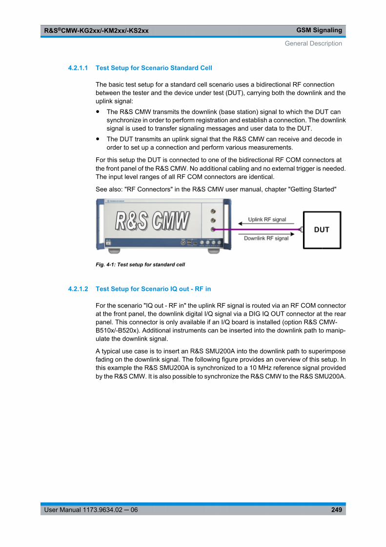
GSM SignalingR&S®CMW-KG2xx/-KM2xx/-KS2xx
249User Manual 1173.9634.02 ─ 06
4.2.1.1 Test Setup for Scenario Standard Cell
The basic test setup for a standard cell scenario uses a bidirectional RF connectionbetween the tester and the device under test (DUT), carrying both the downlink and theuplink signal:● The R&S CMW transmits the downlink (base station) signal to which the DUT can
synchronize in order to perform registration and establish a connection. The downlinksignal is used to transfer signaling messages and user data to the DUT.
● The DUT transmits an uplink signal that the R&S CMW can receive and decode inorder to set up a connection and perform various measurements.
For this setup the DUT is connected to one of the bidirectional RF COM connectors atthe front panel of the R&S CMW. No additional cabling and no external trigger is needed.The input level ranges of all RF COM connectors are identical.
See also: "RF Connectors" in the R&S CMW user manual, chapter "Getting Started"
Fig. 4-1: Test setup for standard cell
4.2.1.2 Test Setup for Scenario IQ out - RF in
For the scenario "IQ out - RF in" the uplink RF signal is routed via an RF COM connectorat the front panel, the downlink digital I/Q signal via a DIG IQ OUT connector at the rearpanel. This connector is only available if an I/Q board is installed (option R&S CMW-B510x/-B520x). Additional instruments can be inserted into the downlink path to manip-ulate the downlink signal.
A typical use case is to insert an R&S SMU200A into the downlink path to superimposefading on the downlink signal. The following figure provides an overview of this setup. Inthis example the R&S SMU200A is synchronized to a 10 MHz reference signal providedby the R&S CMW. It is also possible to synchronize the R&S CMW to the R&S SMU200A.
General Description
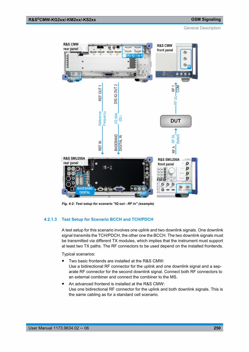
GSM SignalingR&S®CMW-KG2xx/-KM2xx/-KS2xx
250User Manual 1173.9634.02 ─ 06
Fig. 4-2: Test setup for scenario "IQ out - RF in" (example)
4.2.1.3 Test Setup for Scenario BCCH and TCH/PDCH
A test setup for this scenario involves one uplink and two downlink signals. One downlinksignal transmits the TCH/PDCH, the other one the BCCH. The two downlink signals mustbe transmitted via different TX modules, which implies that the instrument must supportat least two TX paths. The RF connectors to be used depend on the installed frontends.
Typical scenarios:● Two basic frontends are installed at the R&S CMW:
Use a bidirectional RF connector for the uplink and one downlink signal and a sep-arate RF connector for the second downlink signal. Connect both RF connectors toan external combiner and connect the combiner to the MS.
● An advanced frontend is installed at the R&S CMW:Use one bidirectional RF connector for the uplink and both downlink signals. This isthe same cabling as for a standard cell scenario.
General Description
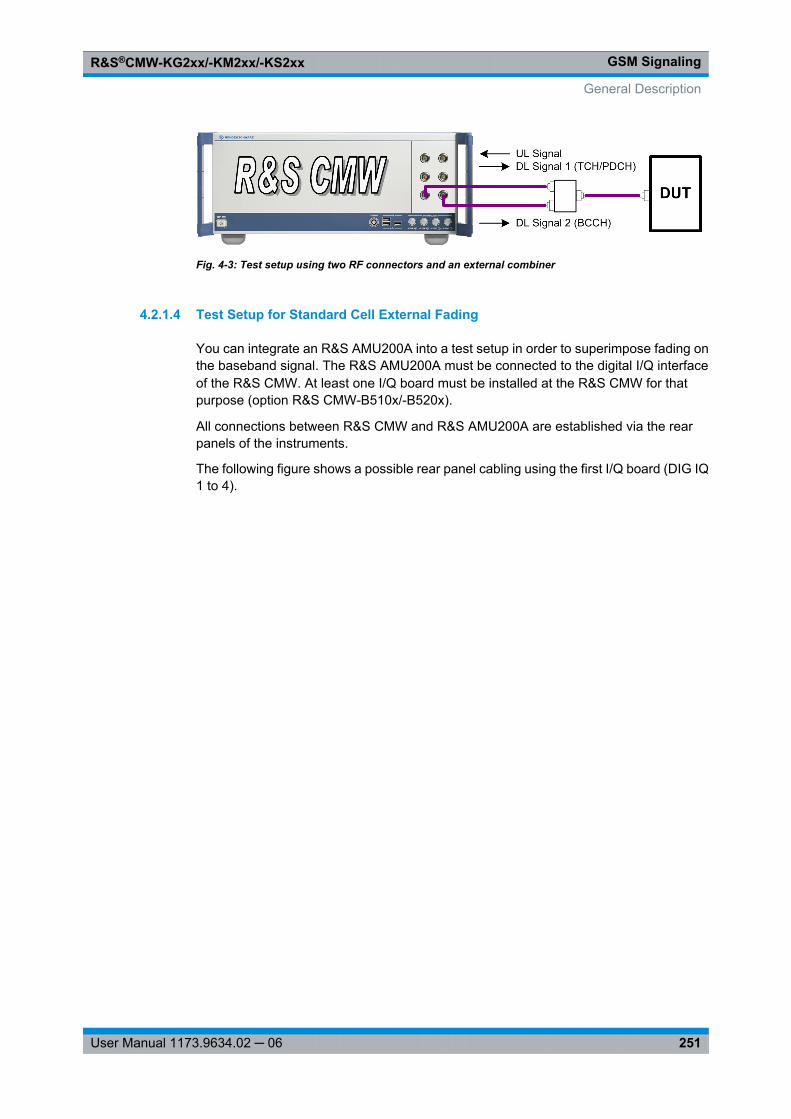
GSM SignalingR&S®CMW-KG2xx/-KM2xx/-KS2xx
251User Manual 1173.9634.02 ─ 06
Fig. 4-3: Test setup using two RF connectors and an external combiner
4.2.1.4 Test Setup for Standard Cell External Fading
You can integrate an R&S AMU200A into a test setup in order to superimpose fading onthe baseband signal. The R&S AMU200A must be connected to the digital I/Q interfaceof the R&S CMW. At least one I/Q board must be installed at the R&S CMW for thatpurpose (option R&S CMW-B510x/-B520x).
All connections between R&S CMW and R&S AMU200A are established via the rearpanels of the instruments.
The following figure shows a possible rear panel cabling using the first I/Q board (DIG IQ1 to 4).
General Description
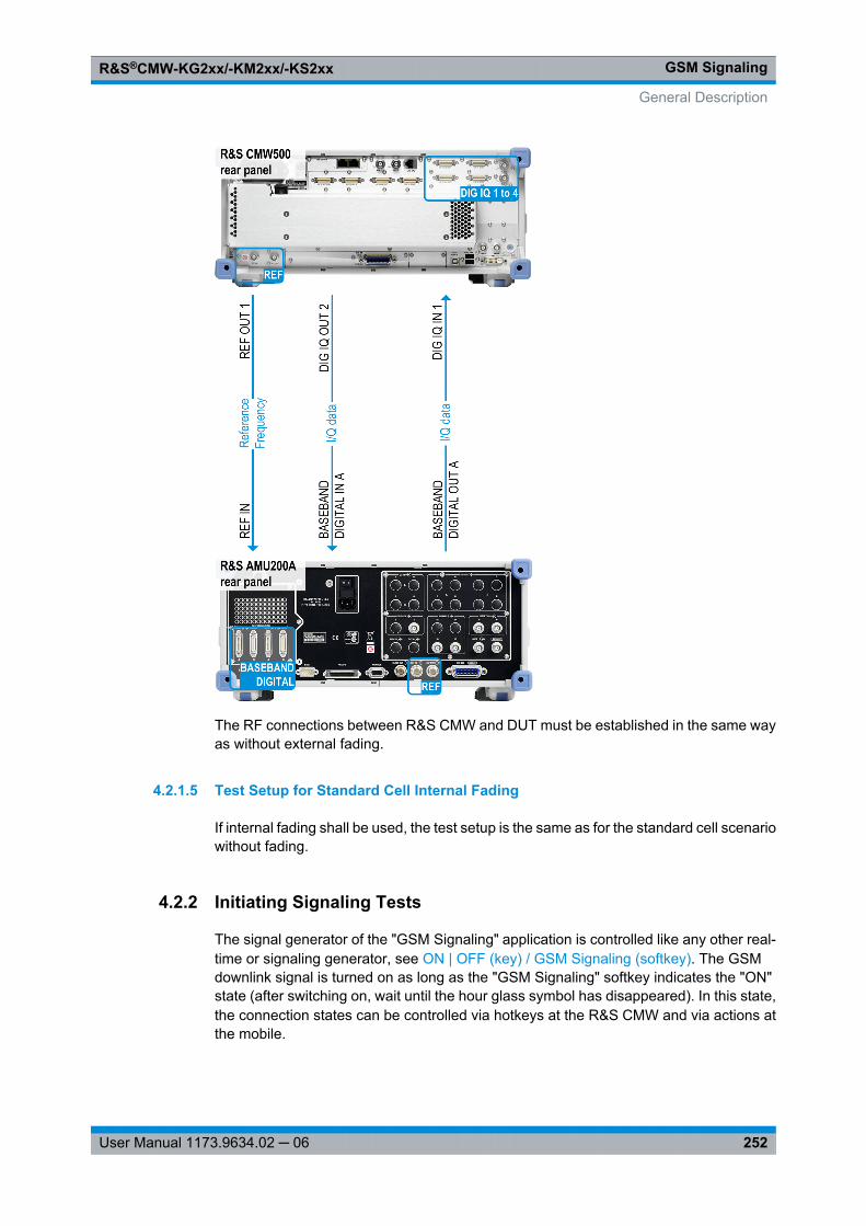
GSM SignalingR&S®CMW-KG2xx/-KM2xx/-KS2xx
252User Manual 1173.9634.02 ─ 06
The RF connections between R&S CMW and DUT must be established in the same wayas without external fading.
4.2.1.5 Test Setup for Standard Cell Internal Fading
If internal fading shall be used, the test setup is the same as for the standard cell scenariowithout fading.
4.2.2 Initiating Signaling Tests
The signal generator of the "GSM Signaling" application is controlled like any other real-time or signaling generator, see ON | OFF (key) / GSM Signaling (softkey). The GSMdownlink signal is turned on as long as the "GSM Signaling" softkey indicates the "ON"state (after switching on, wait until the hour glass symbol has disappeared). In this state,the connection states can be controlled via hotkeys at the R&S CMW and via actions atthe mobile.
General Description
GSM SignalingR&S®CMW-KG2xx/-KM2xx/-KS2xx
253User Manual 1173.9634.02 ─ 06
The default settings of the R&S CMW generally ensure a DL signal with suitable char-acteristics for connection setup. The most important settings can be modified directly inthe main view.
Checks in case of failed registration
If the registration of the mobile fails, check the following R&S CMW settings:● The mobile must support the selected GSM band.● The "DL Reference Level" must be sufficient so that the mobile under test can receive
the DL signal.● The external attenuation settings should be in accordance with characteristics of the
RF connection.● The security settings in the "Network" section of the configuration dialog must be in
accordance with the MS capabilities.Registration can fail if authentication is enabled but not supported by the MS or theSIM card type or secret key do not match.
Checks in case of failed connection setup
If the setup of a PS connection or a PDP context activation fails, check the followingR&S CMW settings:● The PS slot configuration must be compatible to the MS capabilities, especially to the
multislot class.Refer to 3GPP TS 45.002, Annex B for a table listing the individual classes. Themultislot class determines for example the maximum number of DL and UL timeslotsper TDMA frame, the maximum sum of DL+UL timeslots and the minimum distancebetween UL and DL slots.
Performing measurements
The required settings vary depending on the measurement to be performed. However,the general procedure outlined below is applicable to most measurements.
1. Connect your mobile to the R&S CMW (see chapter 4.2.1, "Test Setups",on page 248).
2. Open the "GSM Signaling" firmware application.
3. Configure the signaling application according to the test to be performed.
4. To turn on the DL signal, click/press ON | OFF and wait until the "GSM Signaling"softkey indicates the "ON" state and the hour glass symbol has disappeared.
5. Switch on the mobile phone.
The mobile synchronizes to the DL signal, performs a location update in the CSdomain and attaches to the PS domain (if it supports both domains). The R&S CMWenters the "Synchronized" CS state and the "Attached" PS state.
6. Set up a connection in the CS domain or the PS domain:
a) Click/press the "CS Connect" hotkey and wait until the R&S CMW has enteredthe "Call Established" CS state.
General Description
GSM SignalingR&S®CMW-KG2xx/-KM2xx/-KS2xx
254User Manual 1173.9634.02 ─ 06
b) Click/press the "PS Connect" hotkey and wait until the R&S CMW has enteredthe "TBF Established" PS state.
7. Use the "GSM RX Meas" or "GSM Multi Eval" softkey to switch to the measurementapplication. The GSM RX measurements are provided by the "GSM Signaling" firm-ware application. The GSM multi evaluation measurement is available as optionR&S CMW-KM200.
8. Configure and start the measurement.
Order of stepsThe measurements of the "GSM Signaling" application may be initiated before turning onthe DL signal. In that case the measurement starts as soon as the preconditions arefulfilled. A BER CS measurement for instance starts as soon as the CS connection hasbeen established.
4.2.3 External Fading
An external fading scenario allows to route the downlink baseband signal to anR&S AMU200A that superimposes fading on the signal and routes it back. Thus fadingcan be added to the downlink signal.
Configuring and activating fading
1. Connect the DUT and the R&S AMU200A to the R&S CMW (see chapter 4.2.1.4,"Test Setup for Standard Cell External Fading", on page 251).
2. Configure the signaling application according to the test to be performed, especiallyselect the "Standard Cell Fading" scenario with external fading and configure thedownlink settings.
3. At the signaling application, turn on the downlink signal and set up a connection.
4. In the configuration tree, section "IQ Settings > IQ Out", note the "Baseband PEP"and the "Crest Factor".
5. Configure the R&S AMU200A, especially the following settings:
Reference oscillator settings:
● Source = External● External Reference Frequency = 10 MHz
Baseband input settings for all used connectors:
● Sample Rate = User Defined, 100 MHz● Baseband Input Level: enter the crest factor and the PEP displayed in step 4.
Digital I/Q output settings for all used connectors:
● Sample Rate = User Defined, 100 MHz● Set Level Via = PEP● PEP = PEP value displayed in step 4
General Description
GSM SignalingR&S®CMW-KG2xx/-KM2xx/-KS2xx
255User Manual 1173.9634.02 ─ 06
6. In the R&S AMU200A, activate fading and note the signal level. If you add noise tothe signal, note the signal level without noise.
7. Configure the I/Q input of the R&S CMW:In the configuration tree, section "IQ Settings > IQ In > Baseband Level", enter thesignal level noted in the previous step.Alternatively it is also possible, to specify the signal output level of the R&S AMU200A,to note the resulting PEP and to enter this PEP value at the R&S CMW for "BasebandPEP". But this is not recommended.
8. Turn the downlink signal at the signaling application off and on again.
The configuration is now complete. Fading is active.Note that a reconfiguration of the settings at the R&S AMU200A during an activeconnection to the DUT may result in the loss of the connection or in erroneous mea-surement results.After a reconfiguration of the baseband input settings of the R&S AMU200A, you mustturn the downlink signal at the signaling application off and on again.
Please note that external fading might not work properly, if a frequency-dependentattenuation table is active in downlink direction. When using external fading, deactivatefrequency-dependent attenuation tables for the downlink direction of the used "RF Out-put" connector.
4.2.4 Internal Fading
Testing under realistic air interface conditions is important in order to verify the receiverperformance and the correct operation of the DUT's protocol stack implementation. Forexample bit error rates and throughput performance can be evaluated.
The internal fading module comes with a fading simulator and AWGN generator that canbe selectively enabled. It manipulates the generated downlink I/Q data stream to emulatetypical signal conditions at the DUT's receiver.
The following options are required to use the internal fading simulator in GSM:● one fader I/Q board R&S CMW-B510F or R&S CMW-B520F per signaling instance
using internal fading● one option R&S CMW-KS210 "GSM GPRS EDGE R6, advanced signaling" per sig-
naling instance using fading● a single option R&S CMW-KE100 "Basic Fading support: AWGN generator"● a single option R&S CMW-KE200 "GSM fading profiles TS 45.005, excerpts"
Please note that internal fading might not work properly, if a frequency-dependent attenu-ation table is active in downlink direction. When using internal fading, deactivate fre-quency-dependent attenuation tables for the downlink direction of the used "RF Out-put" connector.
General Description
GSM SignalingR&S®CMW-KG2xx/-KM2xx/-KS2xx
256User Manual 1173.9634.02 ─ 06
4.2.4.1 Fading Simulator
Multi-path fading is an effect which occurs in real world situations. A signal sent from thebase station may take different routes (direct line of sight and/or reflected) and reach thereceiving antenna at different times leading to a sum of phase shifted and, if the receiveris moving, frequency shifted signals.
The internal fading simulator supports multipath propagation conditions defined in AnnexC.3 of 3GPP TS 45.005.
A faded signal has a higher crest factor than an unfaded one. In order to avoid distortion,the baseband signal must be attenuated before entering the fading module, with thenecessary attenuation (insertion loss) depending on the selected fading profile.
In GSM signaling, the insertion loss at the baseband level can be calculated automaticallyor set manually. It is automatically compensated on the HF level, which implies a shift ofthe allowed DL power level range to the same extent, but in opposite direction.
4.2.4.2 AWGN Generator
Additional White Gaussian Noise (AWGN) may lead to a decrease of throughput. Thequality of the received signal is affected by the ratio of the signal power to the surroundingtraffic noise level (signal to noise ratio).
The internal fading module supports AWGN insertion with configurable bandwidth andsignal to noise ratio. Insertion loss at the baseband level is calculated and compensatedautomatically at the HF.
4.2.5 End to End Packet Data Connections
To set up a GSM packet data connection you need the Data Application Unit (DAU) inaddition to the "GSM signaling" application. The DAU itself is available as option R&SCMW-B450A and the DAU measurements as R&S CMW-KM050. For IPv4 option R&SCMW-KA100 is required, for IPv6 additionally option R&S CMW-KA150.
For configuration of the DAU, e.g. for initial configuration of the DAU IP settings, pleaserefer to the DAU documentation.
To set up an end to end packet data connection, proceed as follows:
1. Before switching on the cell signal, ensure that the usage of the DAU is enabled, see"Enable Data end to end" on page 312.
2. Configure any settings as desired.
3. Switch on the cell signal and attach the MS.
4. Initiate a mobile originated packet data connection at the MS.It is not possible to initiate a mobile terminated packet data connection at the instru-ment.
General Description
GSM SignalingR&S®CMW-KG2xx/-KM2xx/-KS2xx
257User Manual 1173.9634.02 ─ 06
When the packet data connection has been established, you can use the DAU to performIP-based data tests (see DAU documentation).
You can also perform "Multi Evaluation" measurements (option R&S CMW-KM200). TheRX measurements provided by the signaling application can not be performed with anend to end packet data connection.
Most measurements require the transmission of data. For a test mode connection thesignaling application takes care of data transmission. For an end to end packet dataconnection the signaling application does not transfer data. So you must generate IPtraffic by other means, e.g. using the DAU. You may for example initiate an IPerf mea-surement or an FTP data transfer. For details refer to the DAU documentation.
Some DAU measurements and applications require to enter the IP address(es) assignedto the MS. You can retrieve this information from the "MS Info" section, see chap-ter 4.4.1.5, "MS Info", on page 303.
4.2.6 Connection States
A GSM core network consists of two service domains, the Circuit Switched (CS) domainand the Packet Switched (PS) domain. The GSM cell emulated by the R&S CMW sup-ports CS services. The additional support of PS services is configurable.
A mobile that supports both CS and PS services can perform a location update in the CSdomain and an attach in the PS domain. The R&S CMW also supports combined attach.
Afterwards a connection can be set up in one domain. The current software version doesnot support simultaneous CS and PS connections (dual transfer mode).
4.2.6.1 CS Connection States
The main Circuit Switched (CS) connection states are described in the following table.
CS State Description
Off No GSM downlink signal transmission
On The R&S CMW emulates a GSM cell, transmitting a DL GSM signal to which the mobilecan synchronize.
MS may or may not be synchronized to the cell signal, but no location update or attach hasbeen performed.
Synchronized Synchronization and location update have been performed.
Alerting The R&S CMW is attempting a connection to the MS. The MS is responding (ringing) butthe connection is not yet established.
Call Established A call to/from the mobile has been established. The R&S CMW can vary connectionparameters, perform transmitter and receiver tests, or initiate a handover.
Control commands initiated by the R&S CMW or by the mobile switch between the CSstates. The following figure shows possible state transitions.
General Description
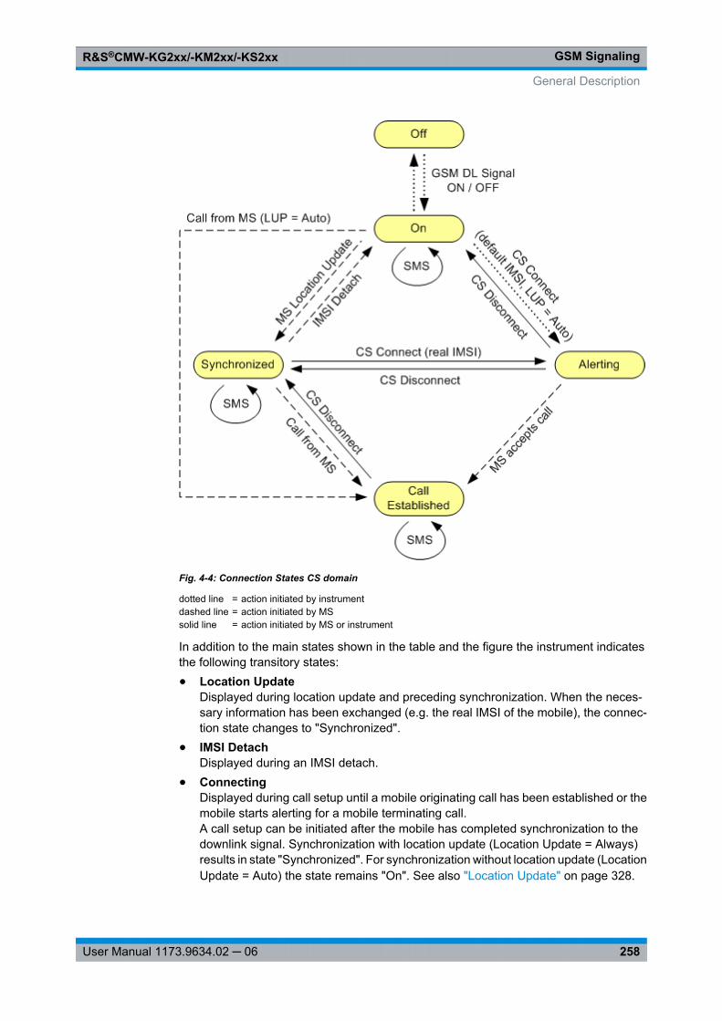
GSM SignalingR&S®CMW-KG2xx/-KM2xx/-KS2xx
258User Manual 1173.9634.02 ─ 06
Fig. 4-4: Connection States CS domain
dotted line = action initiated by instrumentdashed line = action initiated by MSsolid line = action initiated by MS or instrument
In addition to the main states shown in the table and the figure the instrument indicatesthe following transitory states:● Location Update
Displayed during location update and preceding synchronization. When the neces-sary information has been exchanged (e.g. the real IMSI of the mobile), the connec-tion state changes to "Synchronized".
● IMSI DetachDisplayed during an IMSI detach.
● ConnectingDisplayed during call setup until a mobile originating call has been established or themobile starts alerting for a mobile terminating call.A call setup can be initiated after the mobile has completed synchronization to thedownlink signal. Synchronization with location update (Location Update = Always)results in state "Synchronized". For synchronization without location update (LocationUpdate = Auto) the state remains "On". See also "Location Update" on page 328.
General Description
GSM SignalingR&S®CMW-KG2xx/-KM2xx/-KS2xx
259User Manual 1173.9634.02 ─ 06
● ReleasingThe call is being released.
● Sending MessageDisplayed while an SMS message is sent to the MS.
● Receiving MessageDisplayed while an SMS message is received from the MS. To check the receivedmessage see "Incoming > Message Text / Message Length" on page 344.
● Incoming Handover in ProgressDisplayed while an inter-RAT handover from another signaling application is per-formed.
● Outgoing Handover in ProgressDisplayed while an inter-RAT handover to another signaling application is performed.
Additional transitionsThe transitions in the figure above are not complete. The "Off" state can be reached fromany state by turning off the cell signal (ON | OFF). Moreover, incidents like an alertingtimeout or a loss of the radio link cause additional transitions.A GSM dual-band handover can be performed in the "Call Established" CS state. TheCS state does not change during the handover. See also chapter 4.2.7, "Handover",on page 261.
4.2.6.2 PS Connection States
The main Packet Switched (PS) connection states are described in the following table.
PS State Description
Off No signal transmission.
On (Idle) The R&S CMW emulates a GSM cell, transmitting a GSM control channel sig-nal. A GPRS mobile station can detect this signal, synchronize to its timing andfrequency and then read the system information. It learns that the instrument(representing the current cell in a real network) supports GPRS services andcan initiate a GPRS attach.
Attached The mobile station is GPRS-attached.
PDP Context Activated A Packet Data Protocol (PDP) context has been activated, triggered by a PDPcontext request from the MS. PDP is a network protocol used by an externalpacket data network interfacing to GPRS.
This state is for example displayed when a packet data end to end connectionhas been successfully set up.
TBF Established A TBF connection has been established.
This state is for example displayed when a test mode connection has beensuccessfully set up.
General Description
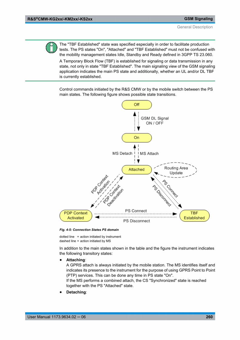
GSM SignalingR&S®CMW-KG2xx/-KM2xx/-KS2xx
260User Manual 1173.9634.02 ─ 06
The "TBF Established" state was specified especially in order to facilitate productiontests. The PS states "On", "Attached" and "TBF Established" must not be confused withthe mobility management states Idle, Standby and Ready defined in 3GPP TS 23.060.A Temporary Block Flow (TBF) is established for signaling or data transmission in anystate, not only in state "TBF Established". The main signaling view of the GSM signalingapplication indicates the main PS state and additionally, whether an UL and/or DL TBFis currently established.
Control commands initiated by the R&S CMW or by the mobile switch between the PSmain states. The following figure shows possible state transitions.
Fig. 4-5: Connection States PS domain
dotted line = action initiated by instrumentdashed line = action initiated by MS
In addition to the main states shown in the table and the figure the instrument indicatesthe following transitory states:● Attaching:
A GPRS attach is always initiated by the mobile station. The MS identifies itself andindicates its presence to the instrument for the purpose of using GPRS Point to Point(PTP) services. This can be done any time in PS state "On".If the MS performs a combined attach, the CS "Synchronized" state is reachedtogether with the PS "Attached" state.
● Detaching:
General Description
GSM SignalingR&S®CMW-KG2xx/-KM2xx/-KS2xx
261User Manual 1173.9634.02 ─ 06
A GPRS detach is always initiated by the mobile station.● Route Area Update:
The mobile performs a routing area update, either triggered by timer T3312 (periodicrouting area update) or because the Routing Area Code (RAC) has been changed.
● PDP Context Activation:A PDP context activation is always triggered by a PDP context request sent by theMS.
● PDP Context Deactivation:A PDP context deactivation is always triggered by the MS.
● Connecting:The R&S CMW attempts to access the "TBF Established" state. The TBF connectionmust be initiated by the instrument.
● ReleasingThe TBF connection is being released (from "TBF Established" to "Attached").
Additional transitions and handoverThe transitions in the figure above are not complete. The "Off" state can be reached fromany state by turning off the cell signal (ON | OFF). Moreover, incidents like a timeout ora loss of the radio link cause additional transitions.A GSM dual-band handover can be performed in the "TBF Established" PS state. ThePS state does not change during the handover. See also chapter 4.2.7, "Handover",on page 261.
4.2.7 Handover
A handover is the process of transferring an ongoing call from one network to another.The R&S CMW supports GSM dual-band handover of circuit switched (CS) or packetswitched (PS) connections between different GSM bands. The "Handover" hotkeyappears in the hotkey bar as soon as the R&S CMW enters the "Call Established" CSconnection state or the "TBF Established" PS connection state.
Handover includes:
1. Selection of the target GSM network ("Destination Selection")
2. Configuration of the essential RF and connection parameters in the destination band("Destination Parameters").
3. Start of the handover process.
After successful handover, the connection is continued in the new band, using the "Des-tination Parameters". The parameters are different for CS and PS connections; see sec-tion "Handover (hotkey)" on page 309.
The handover process can be monitored in the "Connection Status" panel of the "GSMSignaling" main view. "Handover: Dualband" indicates that the connection was handedover to a destination band different from the original GSM band, so that the BCCH andthe TCH are now in different GSM bands. The message disappears when a handover
General Description
GSM SignalingR&S®CMW-KG2xx/-KM2xx/-KS2xx
262User Manual 1173.9634.02 ─ 06
back to the original GSM band is performed and the TCH again uses the same band asthe BCCH.
When the same downlink path is used for BCCH and TCH (e.g. standard cell scenario),the BCCH is usually no longer available after the handover, because the frequencybandwidth supported by a single RF path is too small to cover both the BCCH band andthe TCH band. Using seperate paths for BCCH and TCH (scenario BCCH and TCH/PDCH) guarantees that the BCCH is still available after a dual-band handover.
4.2.8 Trigger Signals
The GSM signaling application provides trigger signals that can be used by otherR&S CMW applications to synchronize to the generated GSM downlink signal. This isespecially useful to trigger GSM TX measurements (option R&S CMW-KM200).
The available trigger signals are described below. All of them are high-pulse TTL signalswith the rising edge at the beginning of a timeslot and a length of exactly 1 symbol.
To address the trigger signals in remote commands, use the following strings, with <i>replaced by the instance number of the signaling application:● "GSM Sig<i>: FrameTrigger"● "GSM Sig<i>: HoppingTrigger"● "GSM Sig<i>: Control ACK"
Frame Trigger
The frame trigger signal is aligned to the beginning of uplink timeslot 0. You can configurewhether it is generated for each uplink frame, for each uplink frame except idle frames(single frame trigger) or for each 26th, 52nd or 104th uplink frame (multiframe trigger).
Multiframe trigger signals can be used to synchronize to the full GSM frame timing of theR&S CMW.
For configuration see chapter 4.4.9, "Trigger Signal Settings", on page 343.
Hopping Trigger
The hopping trigger signal is aligned to the beginning of downlink timeslot 0 of each TDMAframe (including the idle frames).
It is generated while the following two conditions are met:● A connection has been established (CS state "Call Established" or PS state "TBF
Established") and this state has been reached at least 30 TDMA frames ago.● Frequency hopping of the R&S CMW is enabled (see "TCH/PDCH > Carrier 1/2 >
Hopping > Enable" on page 319) and the R&S CMW has encountered the first chan-nel in the hopping list (entry number 0).
The R&S CMW performs frequency hopping according to 3GPP TS 45.002 using theconfigured hopping list. The frequency of the BS signal is changed after each TDMAframe. Depending on the Mobile Allocation Index Offset (MAIO), hopping does not nec-essarily start from the beginning of the sequence. The first hopping trigger pulse occurswhen the first channel in the hopping list (MAI = 0) is used for the first time.
General Description
GSM SignalingR&S®CMW-KG2xx/-KM2xx/-KS2xx
263User Manual 1173.9634.02 ─ 06
Control ACK Trigger
The Control ACK trigger event occurs with each EGPRS UL radio block carrying ControlACK information. As an EGPRS UL radio block consists of 4 TDMA frames, each triggerevent consists of 4 trigger signals. The Control ACK trigger signal is aligned to the begin-ning of uplink timeslot 0.
In contrast to the other EGPRS blocks, CTRL_ACK blocks are transferred on eitherGMSK-modulated normal bursts or on access bursts (see "Control Ack Type"on page 342). Thus the Control ACK trigger signal can be used to analyze access burstswith the "GSM Multi Evaluation" measurement.
4.2.9 BER CS Measurement
The Bit Error Rate (BER) measurement for Circuit Switched (CS) connections is installedtogether with the "GSM Signaling" application. It provides a separate measurement taband configuration dialog and can be enabled in the "Measurement Controller" dialog,entry "RX Measurement...".
The BER CS measurement provides several measurement modes, using different mea-surement principles.
Some measurement modes involve a test loop at the mobile. In these modes the mea-surement evaluates the data returned by the mobile under consideration of the sent datain order to test the performance of the mobile station receiver.
The detected errors are usually produced on the way from the instrument to the MS.Transmission errors produced on the way back (from the MS to the instrument) can usu-ally be neglected because a higher signal level is used in uplink direction. However, insome measurement modes the MS calculates a CRC value for the looped back data.Thus data destroyed on the way back can be detected in a cyclic redundancy check inthe R&S CMW and is ignored for the calculation of transmission errors.
The measurement modes and the related measurement results are described in the fol-lowing sections. You can configure the mode via a hotkey or via the configuration dialog,see "Measure Mode" on page 349.
The burst by burst mode is included in R&S CMW-KS200. The other modes require R&SCMW-KS210.
Test SIMMost mobiles require a test SIM in order to close a test loop. Rohde & Schwarz providesan appropriate test SIM card (R&S CMW-Z04, stock no. 1207.9901.02).
4.2.9.1 Test Procedure
For BER CS measurements a Circuit Switched (CS) connection is required.
The measurement involves the following stages:
1. Configure the "GSM Signaling" application.
General Description
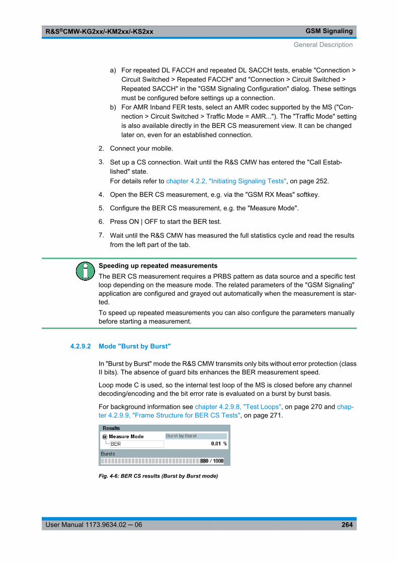
GSM SignalingR&S®CMW-KG2xx/-KM2xx/-KS2xx
264User Manual 1173.9634.02 ─ 06
a) For repeated DL FACCH and repeated DL SACCH tests, enable "Connection >Circuit Switched > Repeated FACCH" and "Connection > Circuit Switched >Repeated SACCH" in the "GSM Signaling Configuration" dialog. These settingsmust be configured before settings up a connection.
b) For AMR Inband FER tests, select an AMR codec supported by the MS ("Con-nection > Circuit Switched > Traffic Mode = AMR..."). The "Traffic Mode" settingis also available directly in the BER CS measurement view. It can be changedlater on, even for an established connection.
2. Connect your mobile.
3. Set up a CS connection. Wait until the R&S CMW has entered the "Call Estab-lished" state.For details refer to chapter 4.2.2, "Initiating Signaling Tests", on page 252.
4. Open the BER CS measurement, e.g. via the "GSM RX Meas" softkey.
5. Configure the BER CS measurement, e.g. the "Measure Mode".
6. Press ON | OFF to start the BER test.
7. Wait until the R&S CMW has measured the full statistics cycle and read the resultsfrom the left part of the tab.
Speeding up repeated measurementsThe BER CS measurement requires a PRBS pattern as data source and a specific testloop depending on the measure mode. The related parameters of the "GSM Signaling"application are configured and grayed out automatically when the measurement is star-ted.To speed up repeated measurements you can also configure the parameters manuallybefore starting a measurement.
4.2.9.2 Mode "Burst by Burst"
In "Burst by Burst" mode the R&S CMW transmits only bits without error protection (classII bits). The absence of guard bits enhances the BER measurement speed.
Loop mode C is used, so the internal test loop of the MS is closed before any channeldecoding/encoding and the bit error rate is evaluated on a burst by burst basis.
For background information see chapter 4.2.9.8, "Test Loops", on page 270 and chap-ter 4.2.9.9, "Frame Structure for BER CS Tests", on page 271.
Fig. 4-6: BER CS results (Burst by Burst mode)
General Description
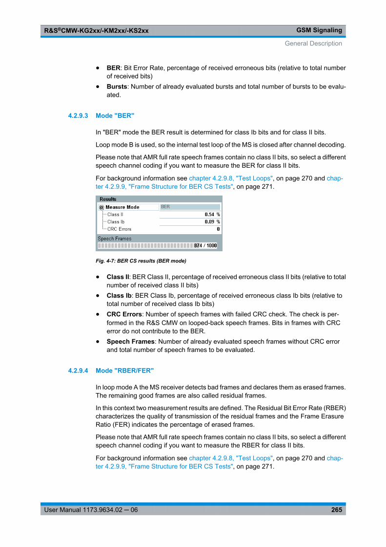
GSM SignalingR&S®CMW-KG2xx/-KM2xx/-KS2xx
265User Manual 1173.9634.02 ─ 06
● BER: Bit Error Rate, percentage of received erroneous bits (relative to total numberof received bits)
● Bursts: Number of already evaluated bursts and total number of bursts to be evalu-ated.
4.2.9.3 Mode "BER"
In "BER" mode the BER result is determined for class Ib bits and for class II bits.
Loop mode B is used, so the internal test loop of the MS is closed after channel decoding.
Please note that AMR full rate speech frames contain no class II bits, so select a differentspeech channel coding if you want to measure the BER for class II bits.
For background information see chapter 4.2.9.8, "Test Loops", on page 270 and chap-ter 4.2.9.9, "Frame Structure for BER CS Tests", on page 271.
Fig. 4-7: BER CS results (BER mode)
● Class II: BER Class II, percentage of received erroneous class II bits (relative to totalnumber of received class II bits)
● Class Ib: BER Class Ib, percentage of received erroneous class Ib bits (relative tototal number of received class Ib bits)
● CRC Errors: Number of speech frames with failed CRC check. The check is per-formed in the R&S CMW on looped-back speech frames. Bits in frames with CRCerror do not contribute to the BER.
● Speech Frames: Number of already evaluated speech frames without CRC errorand total number of speech frames to be evaluated.
4.2.9.4 Mode "RBER/FER"
In loop mode A the MS receiver detects bad frames and declares them as erased frames.The remaining good frames are also called residual frames.
In this context two measurement results are defined. The Residual Bit Error Rate (RBER)characterizes the quality of transmission of the residual frames and the Frame ErasureRatio (FER) indicates the percentage of erased frames.
Please note that AMR full rate speech frames contain no class II bits, so select a differentspeech channel coding if you want to measure the RBER for class II bits.
For background information see chapter 4.2.9.8, "Test Loops", on page 270 and chap-ter 4.2.9.9, "Frame Structure for BER CS Tests", on page 271.
General Description
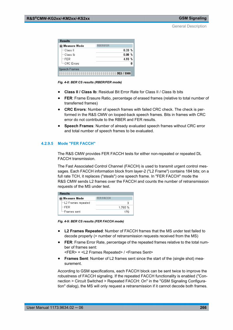
GSM SignalingR&S®CMW-KG2xx/-KM2xx/-KS2xx
266User Manual 1173.9634.02 ─ 06
Fig. 4-8: BER CS results (RBER/FER mode)
● Class II / Class Ib: Residual Bit Error Rate for Class II / Class Ib bits● FER: Frame Erasure Ratio, percentage of erased frames (relative to total number of
transferred frames)● CRC Errors: Number of speech frames with failed CRC check. The check is per-
formed in the R&S CMW on looped-back speech frames. Bits in frames with CRCerror do not contribute to the RBER and FER results.
● Speech Frames: Number of already evaluated speech frames without CRC errorand total number of speech frames to be evaluated.
4.2.9.5 Mode "FER FACCH"
The R&S CMW provides FER FACCH tests for either non-repeated or repeated DLFACCH transmission.
The Fast Associated Control Channel (FACCH) is used to transmit urgent control mes-sages. Each FACCH information block from layer-2 ("L2 Frame") contains 184 bits; on afull rate TCH, it replaces ("steals") one speech frame. In "FER FACCH" mode theR&S CMW sends L2 frames over the FACCH and counts the number of retransmissionrequests of the MS under test.
Fig. 4-9: BER CS results (FER FACCH mode)
● L2 Frames Repeated: Number of FACCH frames that the MS under test failed todecode properly (= number of retransmission requests received from the MS)
● FER: Frame Error Rate, percentage of the repeated frames relative to the total num-ber of frames sent:<FER> = <L2 Frames Repeated> / <Frames Sent>
● Frames Sent: Number of L2 frames sent since the start of the (single shot) mea-surement.
According to GSM specifications, each FACCH block can be sent twice to improve therobustness of FACCH signaling. If the repeated FACCH functionality is enabled ("Con-nection > Circuit Switched > Repeated FACCH: On" in the "GSM Signaling Configura-tion" dialog), the MS will only request a retransmission if it cannot decode both frames.
General Description
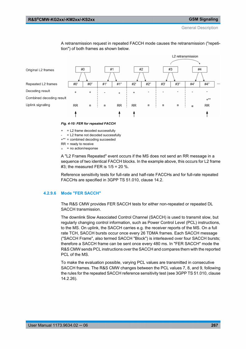
GSM SignalingR&S®CMW-KG2xx/-KM2xx/-KS2xx
267User Manual 1173.9634.02 ─ 06
A retransmission request in repeated FACCH mode causes the retransmission ("repeti-tion") of both frames as shown below.
Fig. 4-10: FER for repeated FACCH
+ = L2 frame decoded successfully- = L2 frame not decoded successfully+** = combined decoding succeededRR = ready to receive⌑ = no action/response
A "L2 Frames Repeated" event occurs if the MS does not send an RR message in asequence of two identical FACCH blocks. In the example above, this occurs for L2 frame#3; the measured FER is 1/5 = 20 %.
Reference sensitivity tests for full-rate and half-rate FACCHs and for full-rate repeatedFACCHs are specified in 3GPP TS 51.010, clause 14.2.
4.2.9.6 Mode "FER SACCH"
The R&S CMW provides FER SACCH tests for either non-repeated or repeated DLSACCH transmission.
The downlink Slow Associated Control Channel (SACCH) is used to transmit slow, butregularly changing control information, such as Power Control Level (PCL) instructions,to the MS. On uplink, the SACCH carries e.g. the receiver reports of the MS. On a fullrate TCH, SACCH bursts occur once every 26 TDMA frames. Each SACCH message("SACCH Frame", also termed SACCH "Block") is interleaved over four SACCH bursts;therefore a SACCH frame can be sent once every 480 ms. In "FER SACCH" mode theR&S CMW sends PCL instructions over the SACCH and compares them with the reportedPCL of the MS.
To make the evaluation possible, varying PCL values are transmitted in consecutiveSACCH frames. The R&S CMW changes between the PCL values 7, 8, and 9, followingthe rules for the repeated SACCH reference sensitivity test (see 3GPP TS 51.010, clause14.2.26).
General Description
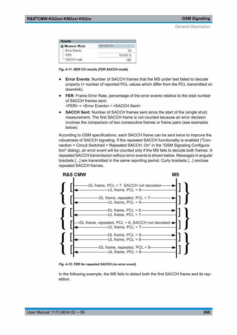
GSM SignalingR&S®CMW-KG2xx/-KM2xx/-KS2xx
268User Manual 1173.9634.02 ─ 06
Fig. 4-11: BER CS results (FER SACCH mode)
● Error Events: Number of SACCH frames that the MS under test failed to decodeproperly (= number of reported PCL values which differ from the PCL transmitted ondownlink).
● FER: Frame Error Rate, percentage of the error events relative to the total numberof SACCH frames sent:<FER> = <Error Events> / <SACCH Sent>
● SACCH Sent: Number of SACCH frames sent since the start of the (single shot)measurement. The first SACCH frame is not counted because an error decisioninvolves the comparison of two consecutive frames or frame pairs (see examplesbelow).
According to GSM specifications, each SACCH frame can be sent twice to improve therobustness of SACCH signaling. If the repeated SACCH functionality is enabled ("Con-nection > Circuit Switched > Repeated SACCH: On" in the "GSM Signaling Configura-tion" dialog), an error event will be counted only if the MS fails to decode both frames. Arepeated SACCH transmission without error events is shown below. Messages in angularbrackets [...] are transmitted in the same reporting period. Curly brackets {...} encloserepeated SACCH frames.
Fig. 4-12: FER for repeated SACCH (no error event)
In the following example, the MS fails to detect both the first SACCH frame and its rep-etition.
General Description
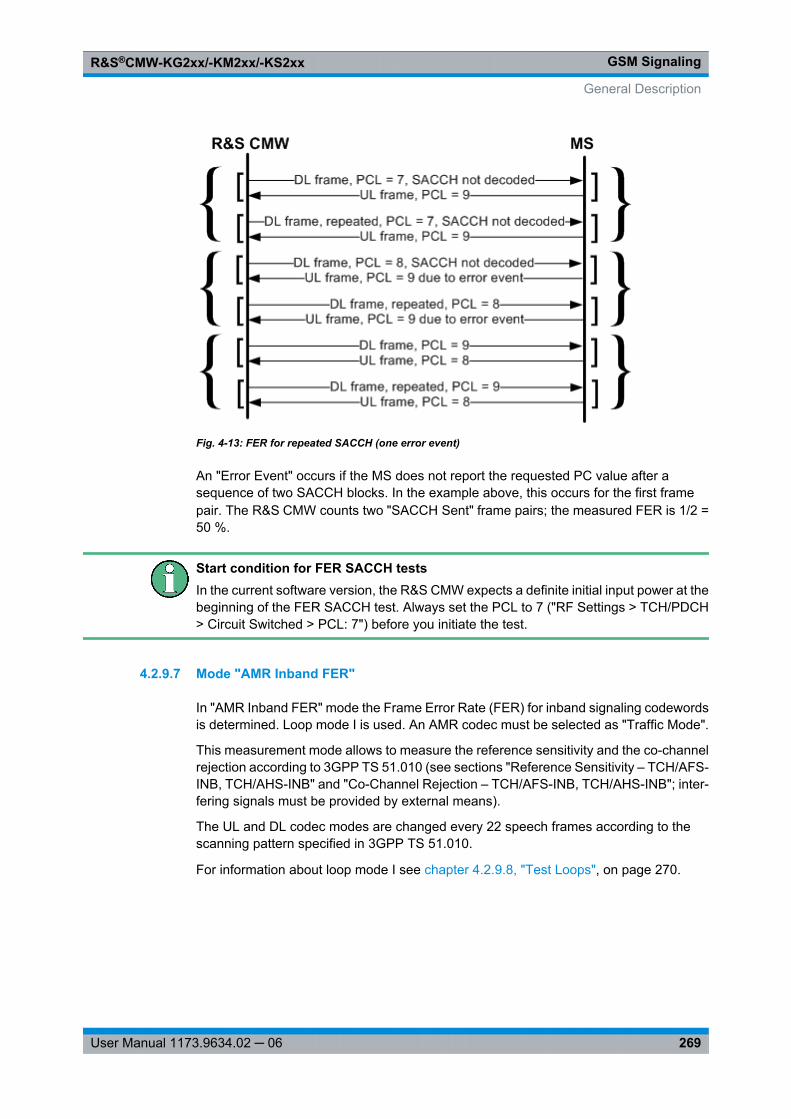
GSM SignalingR&S®CMW-KG2xx/-KM2xx/-KS2xx
269User Manual 1173.9634.02 ─ 06
Fig. 4-13: FER for repeated SACCH (one error event)
An "Error Event" occurs if the MS does not report the requested PC value after asequence of two SACCH blocks. In the example above, this occurs for the first framepair. The R&S CMW counts two "SACCH Sent" frame pairs; the measured FER is 1/2 =50 %.
Start condition for FER SACCH testsIn the current software version, the R&S CMW expects a definite initial input power at thebeginning of the FER SACCH test. Always set the PCL to 7 ("RF Settings > TCH/PDCH> Circuit Switched > PCL: 7") before you initiate the test.
4.2.9.7 Mode "AMR Inband FER"
In "AMR Inband FER" mode the Frame Error Rate (FER) for inband signaling codewordsis determined. Loop mode I is used. An AMR codec must be selected as "Traffic Mode".
This measurement mode allows to measure the reference sensitivity and the co-channelrejection according to 3GPP TS 51.010 (see sections "Reference Sensitivity – TCH/AFS-INB, TCH/AHS-INB" and "Co-Channel Rejection – TCH/AFS-INB, TCH/AHS-INB"; inter-fering signals must be provided by external means).
The UL and DL codec modes are changed every 22 speech frames according to thescanning pattern specified in 3GPP TS 51.010.
For information about loop mode I see chapter 4.2.9.8, "Test Loops", on page 270.
General Description
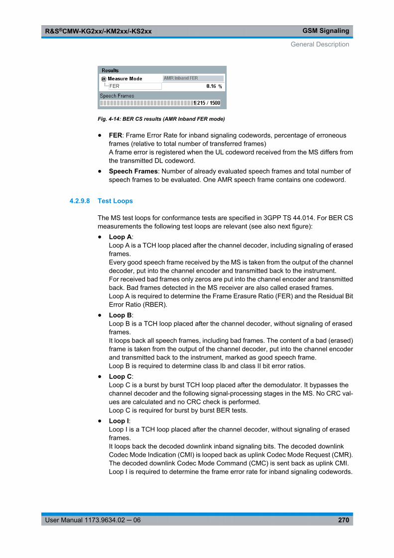
GSM SignalingR&S®CMW-KG2xx/-KM2xx/-KS2xx
270User Manual 1173.9634.02 ─ 06
Fig. 4-14: BER CS results (AMR Inband FER mode)
● FER: Frame Error Rate for inband signaling codewords, percentage of erroneousframes (relative to total number of transferred frames)A frame error is registered when the UL codeword received from the MS differs fromthe transmitted DL codeword.
● Speech Frames: Number of already evaluated speech frames and total number ofspeech frames to be evaluated. One AMR speech frame contains one codeword.
4.2.9.8 Test Loops
The MS test loops for conformance tests are specified in 3GPP TS 44.014. For BER CSmeasurements the following test loops are relevant (see also next figure):● Loop A:
Loop A is a TCH loop placed after the channel decoder, including signaling of erasedframes.Every good speech frame received by the MS is taken from the output of the channeldecoder, put into the channel encoder and transmitted back to the instrument.For received bad frames only zeros are put into the channel encoder and transmittedback. Bad frames detected in the MS receiver are also called erased frames.Loop A is required to determine the Frame Erasure Ratio (FER) and the Residual BitError Ratio (RBER).
● Loop B:Loop B is a TCH loop placed after the channel decoder, without signaling of erasedframes.It loops back all speech frames, including bad frames. The content of a bad (erased)frame is taken from the output of the channel decoder, put into the channel encoderand transmitted back to the instrument, marked as good speech frame.Loop B is required to determine class Ib and class II bit error ratios.
● Loop C:Loop C is a burst by burst TCH loop placed after the demodulator. It bypasses thechannel decoder and the following signal-processing stages in the MS. No CRC val-ues are calculated and no CRC check is performed.Loop C is required for burst by burst BER tests.
● Loop I:Loop I is a TCH loop placed after the channel decoder, without signaling of erasedframes.It loops back the decoded downlink inband signaling bits. The decoded downlinkCodec Mode Indication (CMI) is looped back as uplink Codec Mode Request (CMR).The decoded downlink Codec Mode Command (CMC) is sent back as uplink CMI.Loop I is required to determine the frame error rate for inband signaling codewords.
General Description
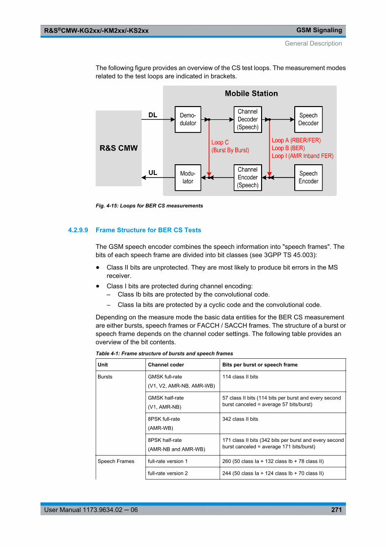
GSM SignalingR&S®CMW-KG2xx/-KM2xx/-KS2xx
271User Manual 1173.9634.02 ─ 06
The following figure provides an overview of the CS test loops. The measurement modesrelated to the test loops are indicated in brackets.
Fig. 4-15: Loops for BER CS measurements
4.2.9.9 Frame Structure for BER CS Tests
The GSM speech encoder combines the speech information into "speech frames". Thebits of each speech frame are divided into bit classes (see 3GPP TS 45.003):
● Class II bits are unprotected. They are most likely to produce bit errors in the MSreceiver.
● Class I bits are protected during channel encoding:– Class Ib bits are protected by the convolutional code.– Class Ia bits are protected by a cyclic code and the convolutional code.
Depending on the measure mode the basic data entities for the BER CS measurementare either bursts, speech frames or FACCH / SACCH frames. The structure of a burst orspeech frame depends on the channel coder settings. The following table provides anoverview of the bit contents.
Table 4-1: Frame structure of bursts and speech frames
Unit Channel coder Bits per burst or speech frame
Bursts GMSK full-rate
(V1, V2, AMR-NB, AMR-WB)
114 class II bits
GMSK half-rate
(V1, AMR-NB)
57 class II bits (114 bits per burst and every secondburst canceled = average 57 bits/burst)
8PSK full-rate
(AMR-WB)
342 class II bits
8PSK half-rate
(AMR-NB and AMR-WB)
171 class II bits (342 bits per burst and every secondburst canceled = average 171 bits/burst)
Speech Frames full-rate version 1 260 (50 class Ia + 132 class Ib + 78 class II)
full-rate version 2 244 (50 class Ia + 124 class Ib + 70 class II)
General Description
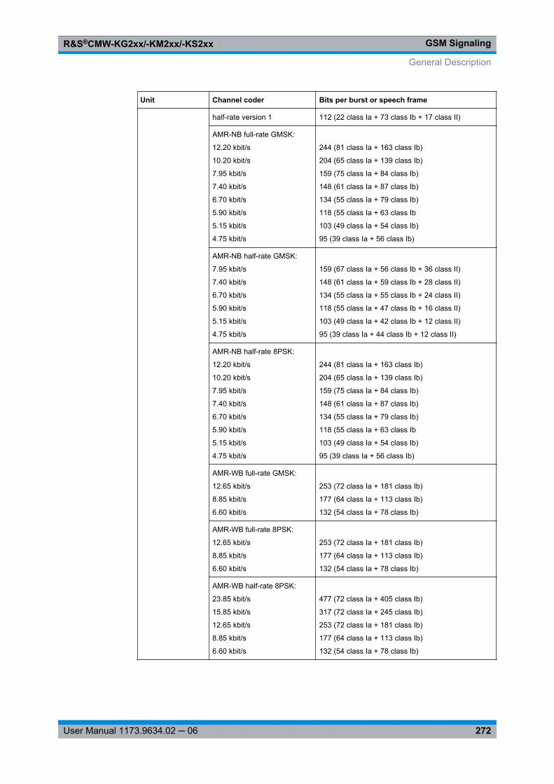
GSM SignalingR&S®CMW-KG2xx/-KM2xx/-KS2xx
272User Manual 1173.9634.02 ─ 06
Unit Channel coder Bits per burst or speech frame
half-rate version 1 112 (22 class Ia + 73 class Ib + 17 class II)
AMR-NB full-rate GMSK:
12.20 kbit/s
10.20 kbit/s
7.95 kbit/s
7.40 kbit/s
6.70 kbit/s
5.90 kbit/s
5.15 kbit/s
4.75 kbit/s
244 (81 class Ia + 163 class Ib)
204 (65 class Ia + 139 class Ib)
159 (75 class Ia + 84 class Ib)
148 (61 class Ia + 87 class Ib)
134 (55 class Ia + 79 class Ib)
118 (55 class Ia + 63 class Ib
103 (49 class Ia + 54 class Ib)
95 (39 class Ia + 56 class Ib)
AMR-NB half-rate GMSK:
7.95 kbit/s
7.40 kbit/s
6.70 kbit/s
5.90 kbit/s
5.15 kbit/s
4.75 kbit/s
159 (67 class Ia + 56 class Ib + 36 class II)
148 (61 class Ia + 59 class Ib + 28 class II)
134 (55 class Ia + 55 class Ib + 24 class II)
118 (55 class Ia + 47 class Ib + 16 class II)
103 (49 class Ia + 42 class Ib + 12 class II)
95 (39 class Ia + 44 class Ib + 12 class II)
AMR-NB half-rate 8PSK:
12.20 kbit/s
10.20 kbit/s
7.95 kbit/s
7.40 kbit/s
6.70 kbit/s
5.90 kbit/s
5.15 kbit/s
4.75 kbit/s
244 (81 class Ia + 163 class Ib)
204 (65 class Ia + 139 class Ib)
159 (75 class Ia + 84 class Ib)
148 (61 class Ia + 87 class Ib)
134 (55 class Ia + 79 class Ib)
118 (55 class Ia + 63 class Ib
103 (49 class Ia + 54 class Ib)
95 (39 class Ia + 56 class Ib)
AMR-WB full-rate GMSK:
12.65 kbit/s
8.85 kbit/s
6.60 kbit/s
253 (72 class Ia + 181 class Ib)
177 (64 class Ia + 113 class Ib)
132 (54 class Ia + 78 class Ib)
AMR-WB full-rate 8PSK:
12.65 kbit/s
8.85 kbit/s
6.60 kbit/s
253 (72 class Ia + 181 class Ib)
177 (64 class Ia + 113 class Ib)
132 (54 class Ia + 78 class Ib)
AMR-WB half-rate 8PSK:
23.85 kbit/s
15.85 kbit/s
12.65 kbit/s
8.85 kbit/s
6.60 kbit/s
477 (72 class Ia + 405 class Ib)
317 (72 class Ia + 245 class Ib)
253 (72 class Ia + 181 class Ib)
177 (64 class Ia + 113 class Ib)
132 (54 class Ia + 78 class Ib)
General Description
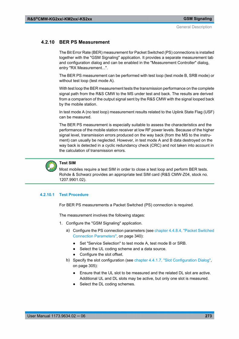
GSM SignalingR&S®CMW-KG2xx/-KM2xx/-KS2xx
273User Manual 1173.9634.02 ─ 06
4.2.10 BER PS Measurement
The Bit Error Rate (BER) measurement for Packet Switched (PS) connections is installedtogether with the "GSM Signaling" application. It provides a separate measurement taband configuration dialog and can be enabled in the "Measurement Controller" dialog,entry "RX Measurement...".
The BER PS measurement can be performed with test loop (test mode B, SRB mode) orwithout test loop (test mode A).
With test loop the BER measurement tests the transmission performance on the completesignal path from the R&S CMW to the MS under test and back. The results are derivedfrom a comparison of the output signal sent by the R&S CMW with the signal looped backby the mobile station.
In test mode A (no test loop) measurement results related to the Uplink State Flag (USF)can be measured.
The BER PS measurement is especially suitable to assess the characteristics and theperformance of the mobile station receiver at low RF power levels. Because of the highersignal level, transmission errors produced on the way back (from the MS to the instru-ment) can usually be neglected. However, in test mode A and B data destroyed on theway back is detected in a cyclic redundancy check (CRC) and not taken into account inthe calculation of transmission errors.
Test SIMMost mobiles require a test SIM in order to close a test loop and perform BER tests.Rohde & Schwarz provides an appropriate test SIM card (R&S CMW-Z04, stock no.1207.9901.02).
4.2.10.1 Test Procedure
For BER PS measurements a Packet Switched (PS) connection is required.
The measurement involves the following stages:
1. Configure the "GSM Signaling" application.
a) Configure the PS connection parameters (see chapter 4.4.8.4, "Packet SwitchedConnection Parameters", on page 340):
● Set "Service Selection" to test mode A, test mode B or SRB.● Select the UL coding scheme and a data source.● Configure the slot offset.
b) Specify the slot configuration (see chapter 4.4.1.7, "Slot Configuration Dialog",on page 305):
● Ensure that the UL slot to be measured and the related DL slot are active.Additional UL and DL slots may be active, but only one slot is measured.
● Select the DL coding schemes.
General Description
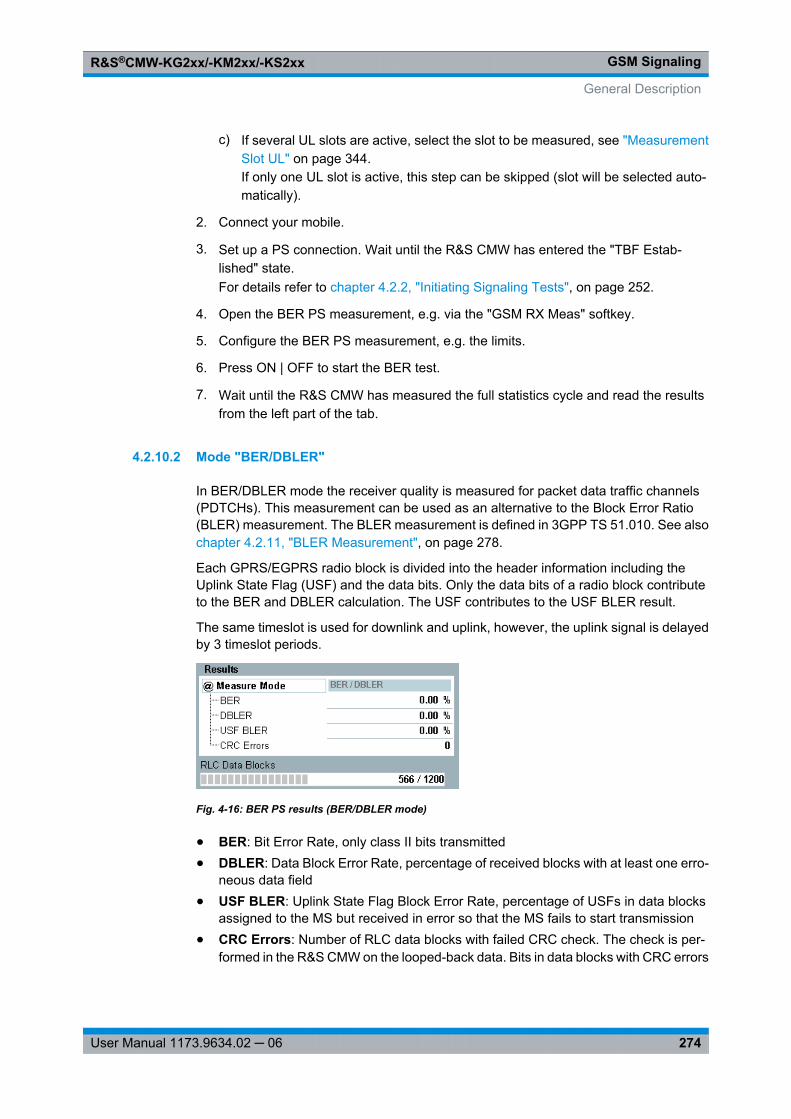
GSM SignalingR&S®CMW-KG2xx/-KM2xx/-KS2xx
274User Manual 1173.9634.02 ─ 06
c) If several UL slots are active, select the slot to be measured, see "MeasurementSlot UL" on page 344.If only one UL slot is active, this step can be skipped (slot will be selected auto-matically).
2. Connect your mobile.
3. Set up a PS connection. Wait until the R&S CMW has entered the "TBF Estab-lished" state.For details refer to chapter 4.2.2, "Initiating Signaling Tests", on page 252.
4. Open the BER PS measurement, e.g. via the "GSM RX Meas" softkey.
5. Configure the BER PS measurement, e.g. the limits.
6. Press ON | OFF to start the BER test.
7. Wait until the R&S CMW has measured the full statistics cycle and read the resultsfrom the left part of the tab.
4.2.10.2 Mode "BER/DBLER"
In BER/DBLER mode the receiver quality is measured for packet data traffic channels(PDTCHs). This measurement can be used as an alternative to the Block Error Ratio(BLER) measurement. The BLER measurement is defined in 3GPP TS 51.010. See alsochapter 4.2.11, "BLER Measurement", on page 278.
Each GPRS/EGPRS radio block is divided into the header information including theUplink State Flag (USF) and the data bits. Only the data bits of a radio block contributeto the BER and DBLER calculation. The USF contributes to the USF BLER result.
The same timeslot is used for downlink and uplink, however, the uplink signal is delayedby 3 timeslot periods.
Fig. 4-16: BER PS results (BER/DBLER mode)
● BER: Bit Error Rate, only class II bits transmitted● DBLER: Data Block Error Rate, percentage of received blocks with at least one erro-
neous data field● USF BLER: Uplink State Flag Block Error Rate, percentage of USFs in data blocks
assigned to the MS but received in error so that the MS fails to start transmission● CRC Errors: Number of RLC data blocks with failed CRC check. The check is per-
formed in the R&S CMW on the looped-back data. Bits in data blocks with CRC errors
General Description
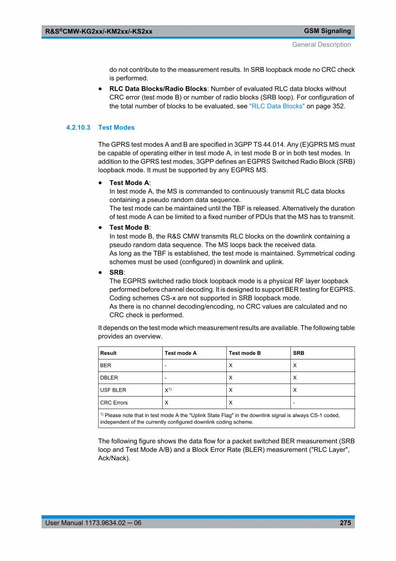
GSM SignalingR&S®CMW-KG2xx/-KM2xx/-KS2xx
275User Manual 1173.9634.02 ─ 06
do not contribute to the measurement results. In SRB loopback mode no CRC checkis performed.
● RLC Data Blocks/Radio Blocks: Number of evaluated RLC data blocks withoutCRC error (test mode B) or number of radio blocks (SRB loop). For configuration ofthe total number of blocks to be evaluated, see "RLC Data Blocks" on page 352.
4.2.10.3 Test Modes
The GPRS test modes A and B are specified in 3GPP TS 44.014. Any (E)GPRS MS mustbe capable of operating either in test mode A, in test mode B or in both test modes. Inaddition to the GPRS test modes, 3GPP defines an EGPRS Switched Radio Block (SRB)loopback mode. It must be supported by any EGPRS MS.
● Test Mode A:In test mode A, the MS is commanded to continuously transmit RLC data blockscontaining a pseudo random data sequence.The test mode can be maintained until the TBF is released. Alternatively the durationof test mode A can be limited to a fixed number of PDUs that the MS has to transmit.
● Test Mode B:In test mode B, the R&S CMW transmits RLC blocks on the downlink containing apseudo random data sequence. The MS loops back the received data.As long as the TBF is established, the test mode is maintained. Symmetrical codingschemes must be used (configured) in downlink and uplink.
● SRB:The EGPRS switched radio block loopback mode is a physical RF layer loopbackperformed before channel decoding. It is designed to support BER testing for EGPRS.Coding schemes CS-x are not supported in SRB loopback mode.As there is no channel decoding/encoding, no CRC values are calculated and noCRC check is performed.
It depends on the test mode which measurement results are available. The following tableprovides an overview.
Result Test mode A Test mode B SRB
BER - X X
DBLER - X X
USF BLER X1) X X
CRC Errors X X -
1) Please note that in test mode A the "Uplink State Flag" in the downlink signal is always CS-1 coded,independent of the currently configured downlink coding scheme.
The following figure shows the data flow for a packet switched BER measurement (SRBloop and Test Mode A/B) and a Block Error Rate (BLER) measurement ("RLC Layer",Ack/Nack).
General Description
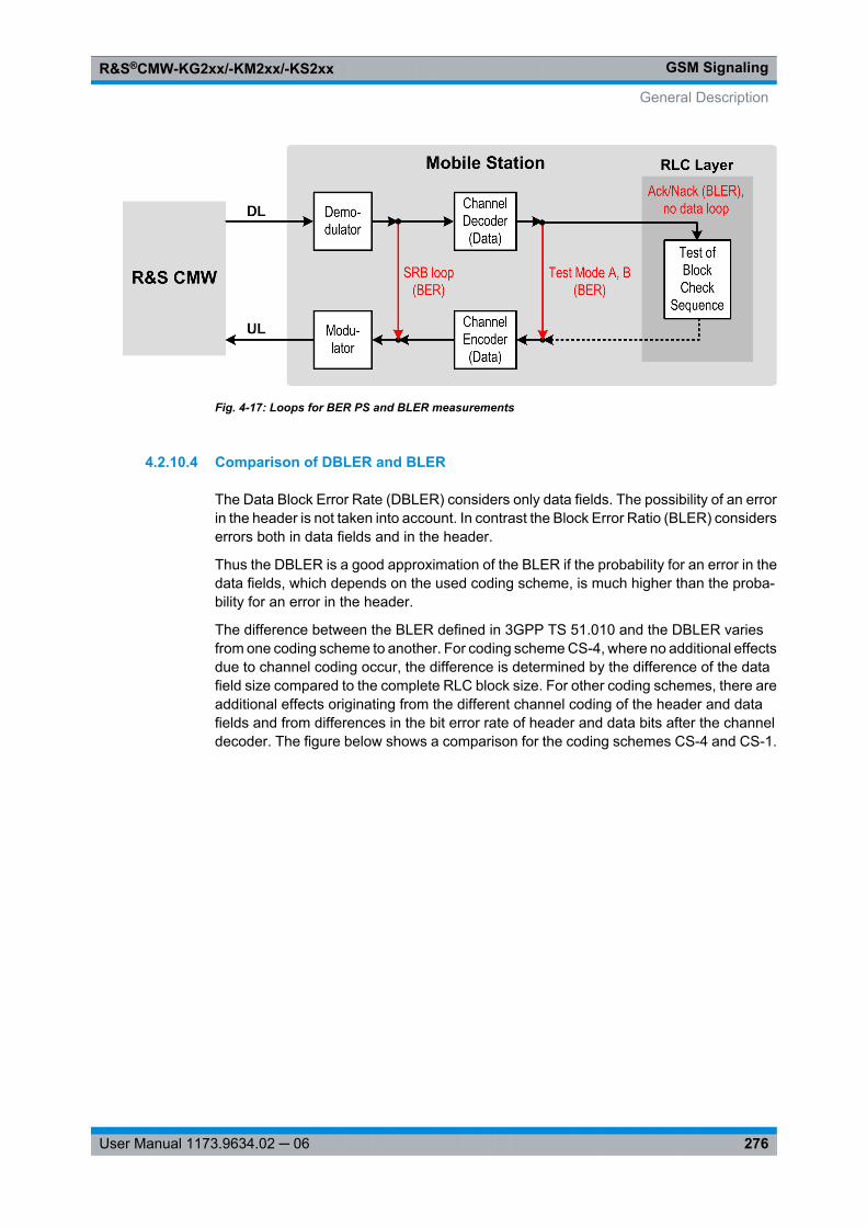
GSM SignalingR&S®CMW-KG2xx/-KM2xx/-KS2xx
276User Manual 1173.9634.02 ─ 06
Fig. 4-17: Loops for BER PS and BLER measurements
4.2.10.4 Comparison of DBLER and BLER
The Data Block Error Rate (DBLER) considers only data fields. The possibility of an errorin the header is not taken into account. In contrast the Block Error Ratio (BLER) considerserrors both in data fields and in the header.
Thus the DBLER is a good approximation of the BLER if the probability for an error in thedata fields, which depends on the used coding scheme, is much higher than the proba-bility for an error in the header.
The difference between the BLER defined in 3GPP TS 51.010 and the DBLER variesfrom one coding scheme to another. For coding scheme CS-4, where no additional effectsdue to channel coding occur, the difference is determined by the difference of the datafield size compared to the complete RLC block size. For other coding schemes, there areadditional effects originating from the different channel coding of the header and datafields and from differences in the bit error rate of header and data bits after the channeldecoder. The figure below shows a comparison for the coding schemes CS-4 and CS-1.
General Description
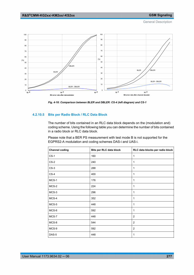
GSM SignalingR&S®CMW-KG2xx/-KM2xx/-KS2xx
277User Manual 1173.9634.02 ─ 06
10 -4 10 -3 10 -2 0
10
20
30
40
50
60
70
80
90
100
[%]
Bit error rate after demodulator
BLER
DBLER
BLER - DBLER
10 -3 10 -2 0
10
20
30
40
50
60
70
80
90
Bit error rate after channel decoder
BLER DBLER
BLER - DBLER
100
[%]
Fig. 4-18: Comparison between BLER and DBLER: CS-4 (left diagram) and CS-1
4.2.10.5 Bits per Radio Block / RLC Data Block
The number of bits contained in an RLC data block depends on the (modulation and)coding scheme. Using the following table you can determine the number of bits containedin a radio block or RLC data block.
Please note that a BER PS measurement with test mode B is not supported for theEGPRS2-A modulation and coding schemes DAS-i and UAS-i.
Channel coding Bits per RLC data block RLC data blocks per radio block
CS-1 160 1
CS-2 240 1
CS-3 288 1
CS-4 400 1
MCS-1 176 1
MCS-2 224 1
MCS-3 296 1
MCS-4 352 1
MCS-5 448 1
MCS-6 592 1
MCS-7 448 2
MCS-8 544 2
MCS-9 592 2
DAS-5 448 1
General Description
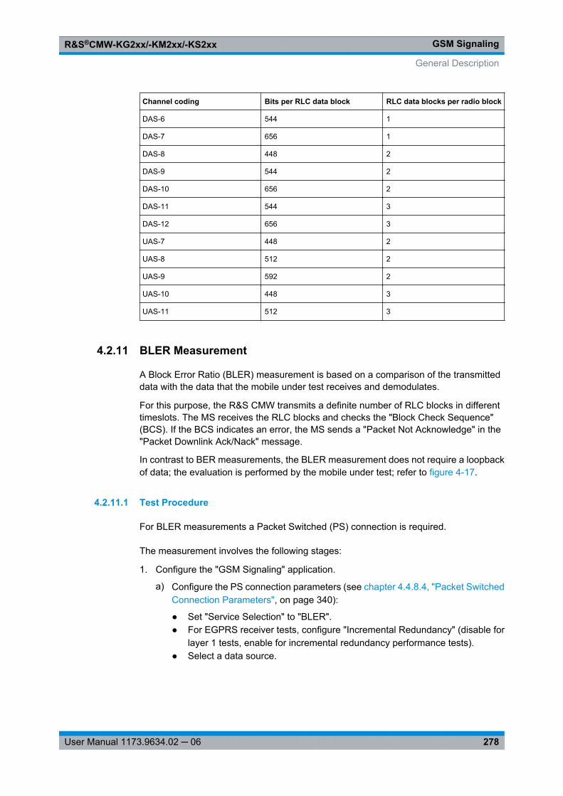
GSM SignalingR&S®CMW-KG2xx/-KM2xx/-KS2xx
278User Manual 1173.9634.02 ─ 06
Channel coding Bits per RLC data block RLC data blocks per radio block
DAS-6 544 1
DAS-7 656 1
DAS-8 448 2
DAS-9 544 2
DAS-10 656 2
DAS-11 544 3
DAS-12 656 3
UAS-7 448 2
UAS-8 512 2
UAS-9 592 2
UAS-10 448 3
UAS-11 512 3
4.2.11 BLER Measurement
A Block Error Ratio (BLER) measurement is based on a comparison of the transmitteddata with the data that the mobile under test receives and demodulates.
For this purpose, the R&S CMW transmits a definite number of RLC blocks in differenttimeslots. The MS receives the RLC blocks and checks the "Block Check Sequence"(BCS). If the BCS indicates an error, the MS sends a "Packet Not Acknowledge" in the"Packet Downlink Ack/Nack" message.
In contrast to BER measurements, the BLER measurement does not require a loopbackof data; the evaluation is performed by the mobile under test; refer to figure 4-17.
4.2.11.1 Test Procedure
For BLER measurements a Packet Switched (PS) connection is required.
The measurement involves the following stages:
1. Configure the "GSM Signaling" application.
a) Configure the PS connection parameters (see chapter 4.4.8.4, "Packet SwitchedConnection Parameters", on page 340):
● Set "Service Selection" to "BLER".● For EGPRS receiver tests, configure "Incremental Redundancy" (disable for
layer 1 tests, enable for incremental redundancy performance tests).● Select a data source.
General Description
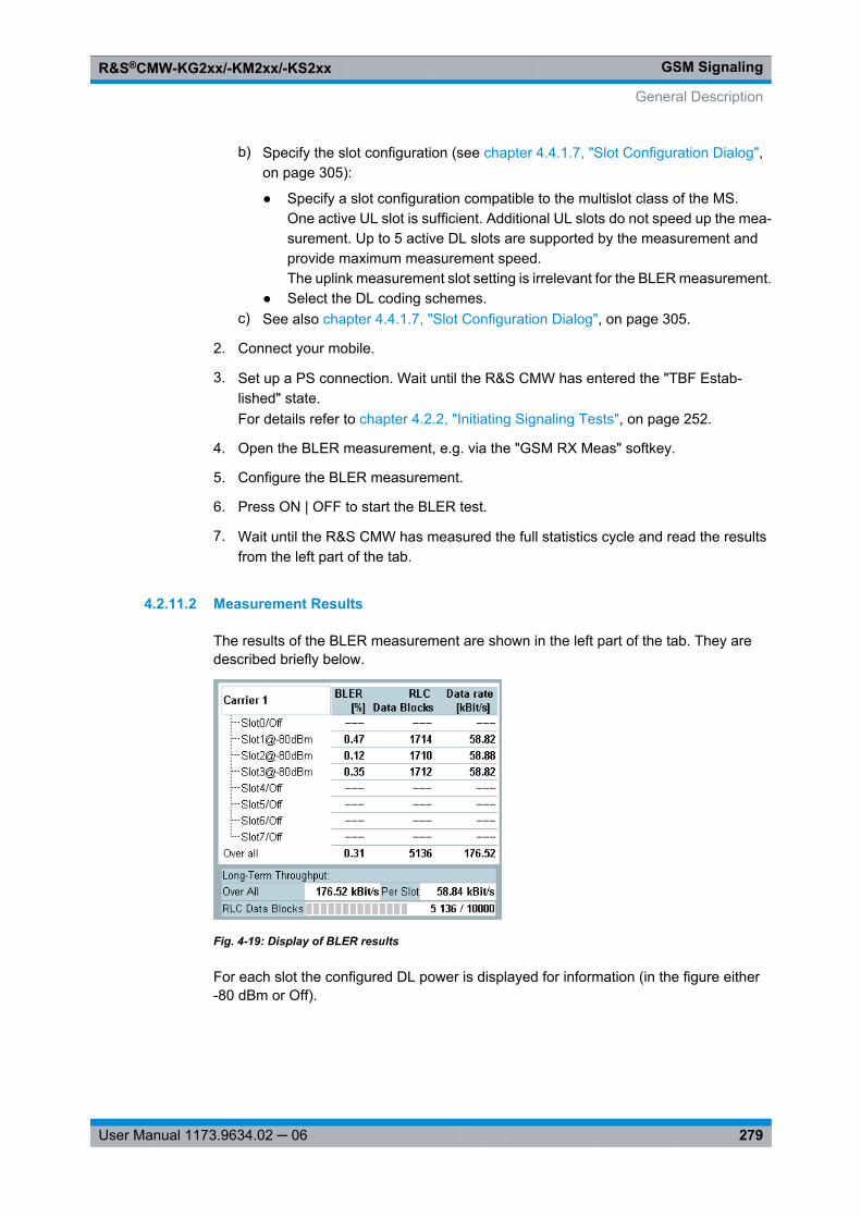
GSM SignalingR&S®CMW-KG2xx/-KM2xx/-KS2xx
279User Manual 1173.9634.02 ─ 06
b) Specify the slot configuration (see chapter 4.4.1.7, "Slot Configuration Dialog",on page 305):
● Specify a slot configuration compatible to the multislot class of the MS.One active UL slot is sufficient. Additional UL slots do not speed up the mea-surement. Up to 5 active DL slots are supported by the measurement andprovide maximum measurement speed.The uplink measurement slot setting is irrelevant for the BLER measurement.
● Select the DL coding schemes.c) See also chapter 4.4.1.7, "Slot Configuration Dialog", on page 305.
2. Connect your mobile.
3. Set up a PS connection. Wait until the R&S CMW has entered the "TBF Estab-lished" state.For details refer to chapter 4.2.2, "Initiating Signaling Tests", on page 252.
4. Open the BLER measurement, e.g. via the "GSM RX Meas" softkey.
5. Configure the BLER measurement.
6. Press ON | OFF to start the BLER test.
7. Wait until the R&S CMW has measured the full statistics cycle and read the resultsfrom the left part of the tab.
4.2.11.2 Measurement Results
The results of the BLER measurement are shown in the left part of the tab. They aredescribed briefly below.
Fig. 4-19: Display of BLER results
For each slot the configured DL power is displayed for information (in the figure either-80 dBm or Off).
General Description
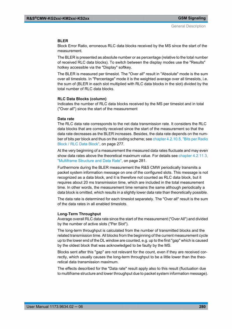
GSM SignalingR&S®CMW-KG2xx/-KM2xx/-KS2xx
280User Manual 1173.9634.02 ─ 06
BLERBlock Error Ratio, erroneous RLC data blocks received by the MS since the start of themeasurement.
The BLER is presented as absolute number or as percentage (relative to the total numberof received RLC data blocks). To switch between the display modes use the "Results"hotkey accessible via the "Display" softkey.
The BLER is measured per timeslot. The "Over all" result in "Absolute" mode is the sumover all timeslots. In "Percentage" mode it is the weighted average over all timeslots, i.e.the sum of (BLER in each slot multiplied with RLC data blocks in the slot) divided by thetotal number of RLC data blocks.
RLC Data Blocks (column)Indicates the number of RLC data blocks received by the MS per timeslot and in total("Over all") since the start of the measurement
Data rateThe RLC data rate corresponds to the net data transmission rate. It considers the RLCdata blocks that are correctly received since the start of the measurement so that thedata rate decreases as the BLER increases. Besides, the data rate depends on the num-ber of bits per block and thus on the coding scheme; see chapter 4.2.10.5, "Bits per RadioBlock / RLC Data Block", on page 277.
At the very beginning of a measurement the measured data rates fluctuate and may evenshow data rates above the theoretical maximum value. For details see chapter 4.2.11.3,"Multiframe Structure and Data Rate", on page 281.
Furthermore during the BLER measurement the R&S CMW periodically transmits apacket system information message on one of the configured slots. This message is notrecognized as a data block, and it is therefore not counted as RLC data block, but itrequires about 20 ms transmission time, which are included in the total measurementtime. In other words, the measurement time remains the same although periodically adata block is omitted, which results in a slightly lower data rate than theoretically possible.
The data rate is determined for each timeslot separately. The "Over all" result is the sumof the data rates in all enabled timeslots.
Long-Term ThroughputAverage overall RLC data rate since the start of the measurement ("Over All") and dividedby the number of active slots ("Per Slot").
The long-term throughput is calculated from the number of transmitted blocks and therelated transmission time. All blocks from the beginning of the current measurement cycleup to the lower end of the DL window are counted, e.g. up to the first "gap" which is causedby the oldest block that was acknowledged to be faulty by the MS.
Blocks sent after this "gap" are not relevant for the count, even if they are received cor-rectly, which usually causes the long-term throughput to be a little lower than the theo-retical data transmission maximum.
The effects described for the "Data rate" result apply also to this result (fluctuation dueto multiframe structure and lower throughput due to packet system information message).
General Description
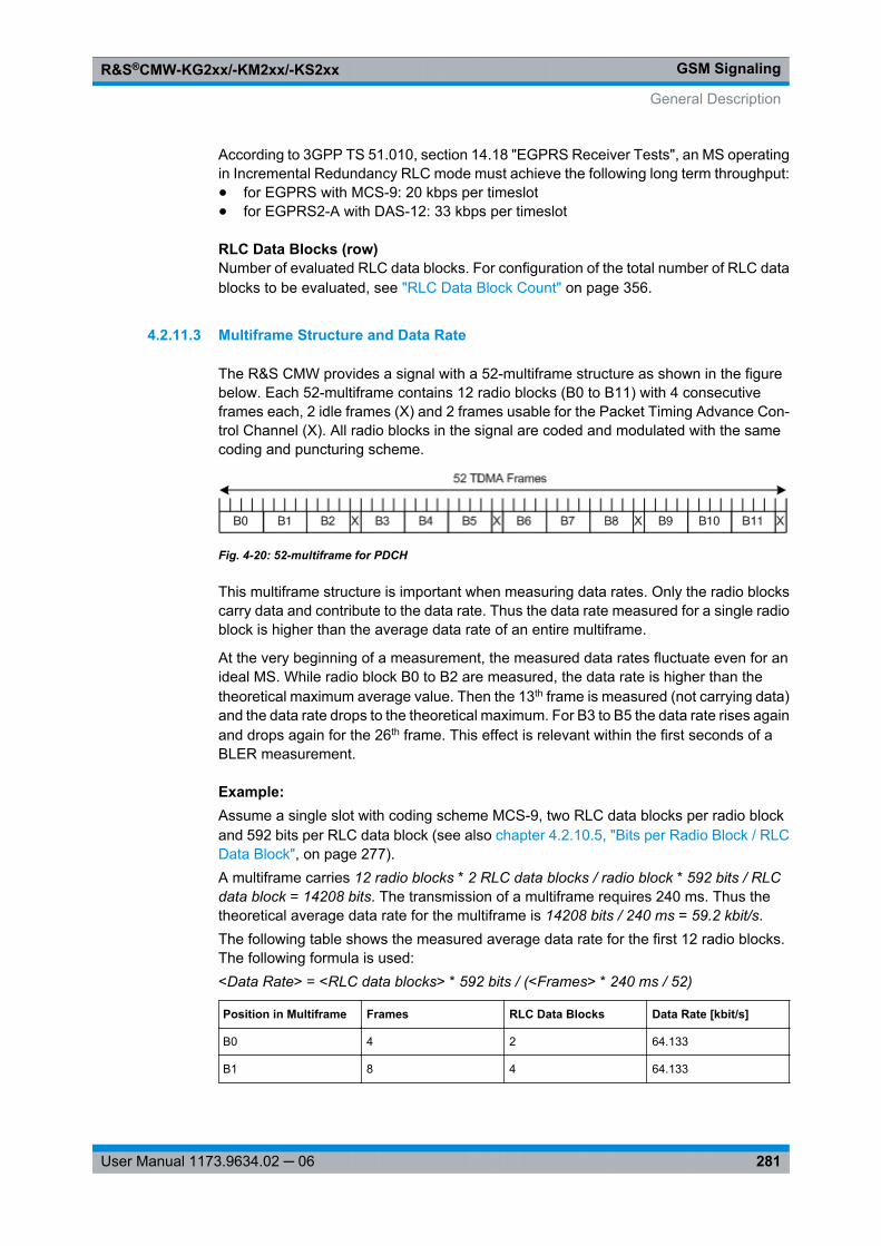
GSM SignalingR&S®CMW-KG2xx/-KM2xx/-KS2xx
281User Manual 1173.9634.02 ─ 06
According to 3GPP TS 51.010, section 14.18 "EGPRS Receiver Tests", an MS operatingin Incremental Redundancy RLC mode must achieve the following long term throughput:● for EGPRS with MCS-9: 20 kbps per timeslot● for EGPRS2-A with DAS-12: 33 kbps per timeslot
RLC Data Blocks (row)Number of evaluated RLC data blocks. For configuration of the total number of RLC datablocks to be evaluated, see "RLC Data Block Count" on page 356.
4.2.11.3 Multiframe Structure and Data Rate
The R&S CMW provides a signal with a 52-multiframe structure as shown in the figurebelow. Each 52-multiframe contains 12 radio blocks (B0 to B11) with 4 consecutiveframes each, 2 idle frames (X) and 2 frames usable for the Packet Timing Advance Con-trol Channel (X). All radio blocks in the signal are coded and modulated with the samecoding and puncturing scheme.
Fig. 4-20: 52-multiframe for PDCH
This multiframe structure is important when measuring data rates. Only the radio blockscarry data and contribute to the data rate. Thus the data rate measured for a single radioblock is higher than the average data rate of an entire multiframe.
At the very beginning of a measurement, the measured data rates fluctuate even for anideal MS. While radio block B0 to B2 are measured, the data rate is higher than thetheoretical maximum average value. Then the 13th frame is measured (not carrying data)and the data rate drops to the theoretical maximum. For B3 to B5 the data rate rises againand drops again for the 26th frame. This effect is relevant within the first seconds of aBLER measurement.
Example: Assume a single slot with coding scheme MCS-9, two RLC data blocks per radio blockand 592 bits per RLC data block (see also chapter 4.2.10.5, "Bits per Radio Block / RLCData Block", on page 277).A multiframe carries 12 radio blocks * 2 RLC data blocks / radio block * 592 bits / RLCdata block = 14208 bits. The transmission of a multiframe requires 240 ms. Thus thetheoretical average data rate for the multiframe is 14208 bits / 240 ms = 59.2 kbit/s.The following table shows the measured average data rate for the first 12 radio blocks.The following formula is used:<Data Rate> = <RLC data blocks> * 592 bits / (<Frames> * 240 ms / 52)
Position in Multiframe Frames RLC Data Blocks Data Rate [kbit/s]
B0 4 2 64.133
B1 8 4 64.133
General Description
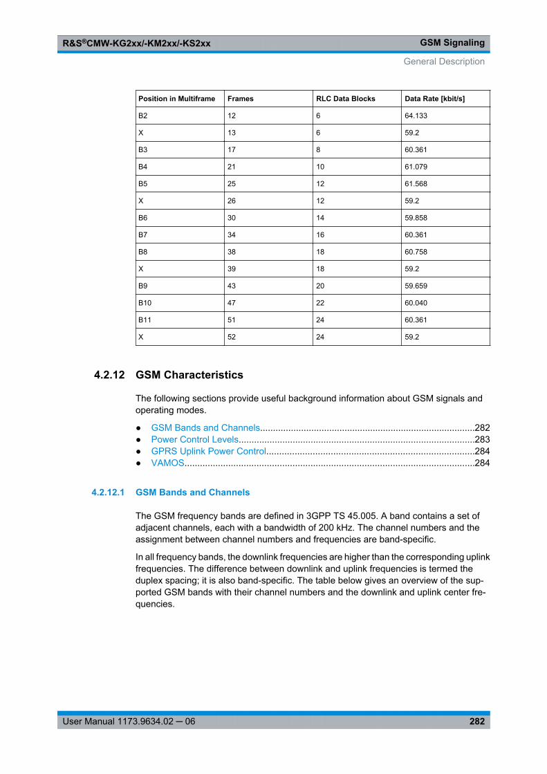
GSM SignalingR&S®CMW-KG2xx/-KM2xx/-KS2xx
282User Manual 1173.9634.02 ─ 06
Position in Multiframe Frames RLC Data Blocks Data Rate [kbit/s]
B2 12 6 64.133
X 13 6 59.2
B3 17 8 60.361
B4 21 10 61.079
B5 25 12 61.568
X 26 12 59.2
B6 30 14 59.858
B7 34 16 60.361
B8 38 18 60.758
X 39 18 59.2
B9 43 20 59.659
B10 47 22 60.040
B11 51 24 60.361
X 52 24 59.2
4.2.12 GSM Characteristics
The following sections provide useful background information about GSM signals andoperating modes.
● GSM Bands and Channels....................................................................................282● Power Control Levels............................................................................................283● GPRS Uplink Power Control.................................................................................284● VAMOS.................................................................................................................284
4.2.12.1 GSM Bands and Channels
The GSM frequency bands are defined in 3GPP TS 45.005. A band contains a set ofadjacent channels, each with a bandwidth of 200 kHz. The channel numbers and theassignment between channel numbers and frequencies are band-specific.
In all frequency bands, the downlink frequencies are higher than the corresponding uplinkfrequencies. The difference between downlink and uplink frequencies is termed theduplex spacing; it is also band-specific. The table below gives an overview of the sup-ported GSM bands with their channel numbers and the downlink and uplink center fre-quencies.
General Description
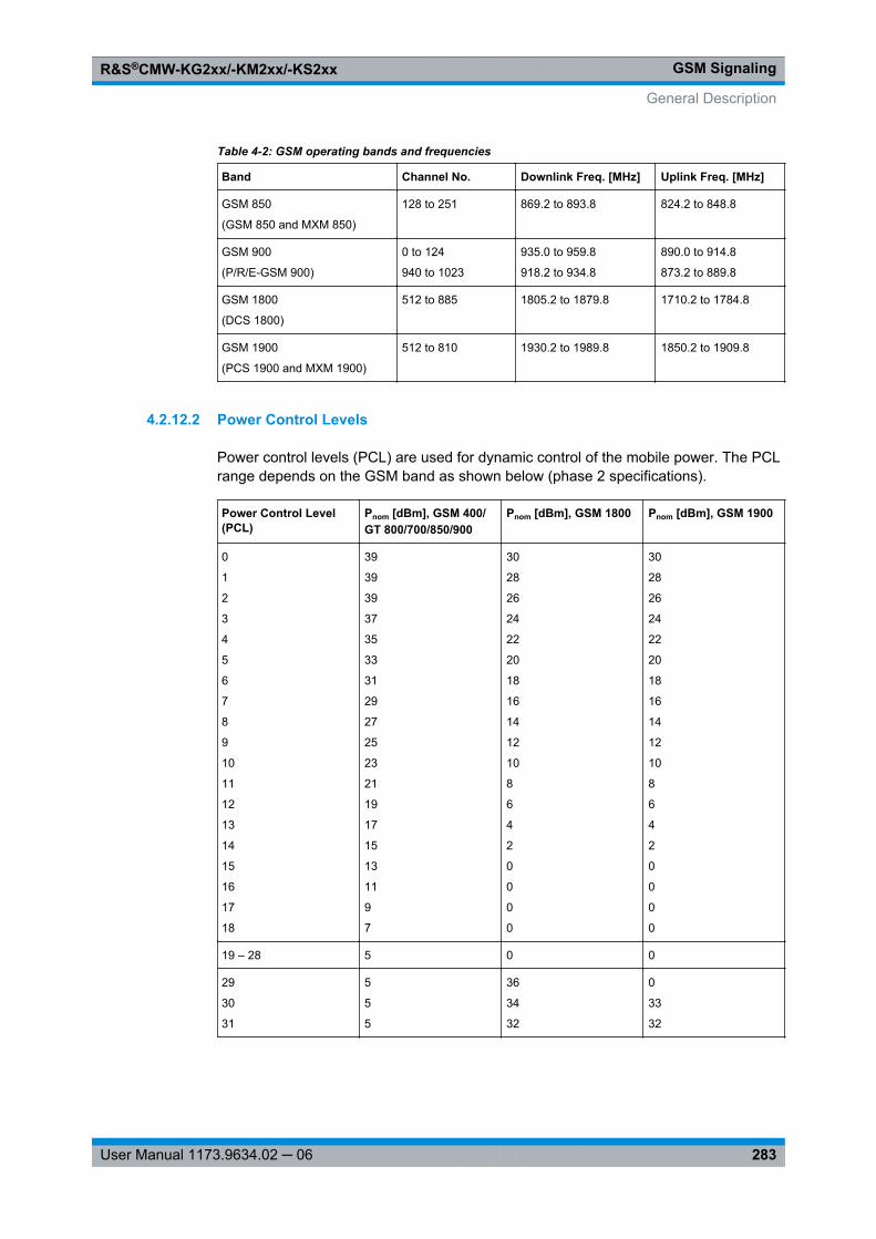
GSM SignalingR&S®CMW-KG2xx/-KM2xx/-KS2xx
283User Manual 1173.9634.02 ─ 06
Table 4-2: GSM operating bands and frequencies
Band Channel No. Downlink Freq. [MHz] Uplink Freq. [MHz]
GSM 850
(GSM 850 and MXM 850)
128 to 251 869.2 to 893.8 824.2 to 848.8
GSM 900
(P/R/E-GSM 900)
0 to 124
940 to 1023
935.0 to 959.8
918.2 to 934.8
890.0 to 914.8
873.2 to 889.8
GSM 1800
(DCS 1800)
512 to 885 1805.2 to 1879.8 1710.2 to 1784.8
GSM 1900
(PCS 1900 and MXM 1900)
512 to 810 1930.2 to 1989.8 1850.2 to 1909.8
4.2.12.2 Power Control Levels
Power control levels (PCL) are used for dynamic control of the mobile power. The PCLrange depends on the GSM band as shown below (phase 2 specifications).
Power Control Level(PCL)
Pnom [dBm], GSM 400/GT 800/700/850/900
Pnom [dBm], GSM 1800 Pnom [dBm], GSM 1900
0
1
2
3
4
5
6
7
8
9
10
11
12
13
14
15
16
17
18
39
39
39
37
35
33
31
29
27
25
23
21
19
17
15
13
11
9
7
30
28
26
24
22
20
18
16
14
12
10
8
6
4
2
0
0
0
0
30
28
26
24
22
20
18
16
14
12
10
8
6
4
2
0
0
0
0
19 – 28 5 0 0
29
30
31
5
5
5
36
34
32
0
33
32
General Description
GSM SignalingR&S®CMW-KG2xx/-KM2xx/-KS2xx
284User Manual 1173.9634.02 ─ 06
4.2.12.3 GPRS Uplink Power Control
Power control of the MS is important for spectral efficiency in the cellular system as wellas for the reduction of power consumption of the mobile station. In circuit switched mode,where a continuous two way connection between the BTS and the MS is maintained,closed loop power control is used: The BTS measures the received signal level from theMS and dynamically adapts the MS output power in 2-dB steps using a fixed scale ofPower Control Levels (PCL), see chapter 2.2.5, "Power Control Levels", on page 15.
In open loop power control, the path loss in downlink and in uplink is assumed to beidentical. If the MS detects a reduction of the received signal level C, it tries to compensatefor the changed propagation conditions by increasing its own output power PCH by thesame amount: The sum of PCH + C is always kept constant. This fast but inaccurate powercontrol mode is useful at the beginning of a packet transmission.
For a discontinuous, packet switched GPRS connection, a combination of open loop andclosed loop power control is used (see 3GPP TS 45.008, Annex B). The RF output powerPCH on each individual uplink PDCH shall be:
PCH = min (Γ0 - ΓCH - α(C+48), PMAX)
where:● Γ0 is a network-specific constant (39 dBm for GSM 400, GSM GT 800, GSM 850 and
GSM 900, 36 dBm for GSM 1800 and GSM 1900, i.e. the maximum nominal outputpower of an MS in the network)
● ΓCH is a power control parameter depending on the MS and channel (analogous tothe PCL in circuit switched mode). The values are in the range 0 to 31, correspondingto relative powers of 0 dB, 2 dB, ..., 62 dB.This parameter is individually configurable per uplink timeslot, see chapter 4.4.1.7,"Slot Configuration Dialog", on page 305.
● α represents a system parameter.A pure open loop power control is achieved by setting α = 1 and keeping ΓCH constant.A closed loop is achieved by setting α = 0. The "GSM Signaling" application alwayssets α = 0.
● PMAX is the maximum allowed output power in the cell. For configuration see "BCCH> PMax (PCL)" on page 317.
Example for PCH calculation
Assumptions: GSM 900 network (Γ0 = 39 dBm), ΓCH = 12, calculated PCH < PMAX
Calculation: PCH = (Γ0 - ΓCH) = 39 dBm - 24 dB = 15 dBm
4.2.12.4 VAMOS
Legacy GSM channel organization allows only one Mobile Station (MS) to use a physicalresource, i.e. a certain frequency channel and timeslot. With VAMOS it is possible toserve two MS simultaneously on the same physical resource. Thus the voice channelcapacity in the CS domain can be doubled. VAMOS stands for "Voice services overAdaptive Multi-user channels on One Slot" and is defined in 3GPP TS 45.001.
General Description
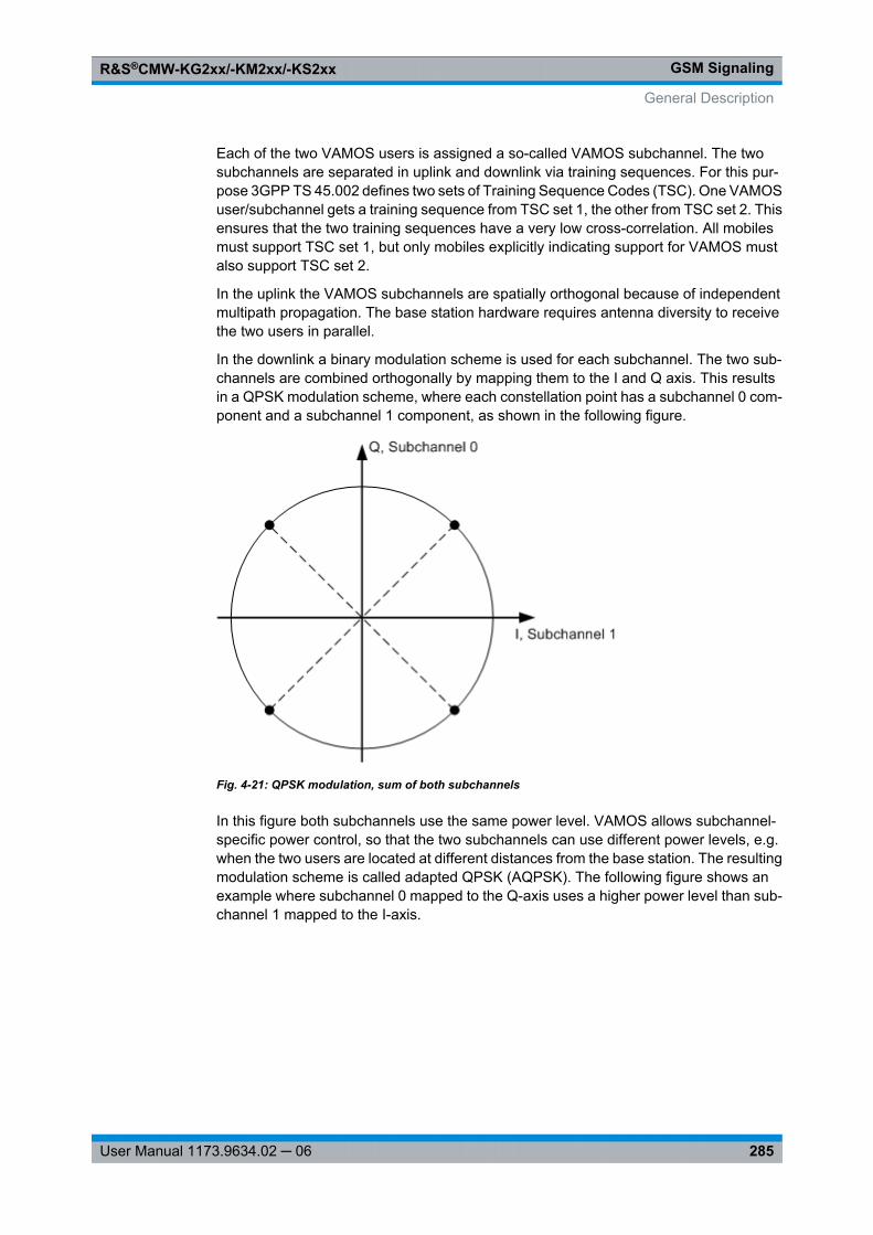
GSM SignalingR&S®CMW-KG2xx/-KM2xx/-KS2xx
285User Manual 1173.9634.02 ─ 06
Each of the two VAMOS users is assigned a so-called VAMOS subchannel. The twosubchannels are separated in uplink and downlink via training sequences. For this pur-pose 3GPP TS 45.002 defines two sets of Training Sequence Codes (TSC). One VAMOSuser/subchannel gets a training sequence from TSC set 1, the other from TSC set 2. Thisensures that the two training sequences have a very low cross-correlation. All mobilesmust support TSC set 1, but only mobiles explicitly indicating support for VAMOS mustalso support TSC set 2.
In the uplink the VAMOS subchannels are spatially orthogonal because of independentmultipath propagation. The base station hardware requires antenna diversity to receivethe two users in parallel.
In the downlink a binary modulation scheme is used for each subchannel. The two sub-channels are combined orthogonally by mapping them to the I and Q axis. This resultsin a QPSK modulation scheme, where each constellation point has a subchannel 0 com-ponent and a subchannel 1 component, as shown in the following figure.
Fig. 4-21: QPSK modulation, sum of both subchannels
In this figure both subchannels use the same power level. VAMOS allows subchannel-specific power control, so that the two subchannels can use different power levels, e.g.when the two users are located at different distances from the base station. The resultingmodulation scheme is called adapted QPSK (AQPSK). The following figure shows anexample where subchannel 0 mapped to the Q-axis uses a higher power level than sub-channel 1 mapped to the I-axis.
General Description
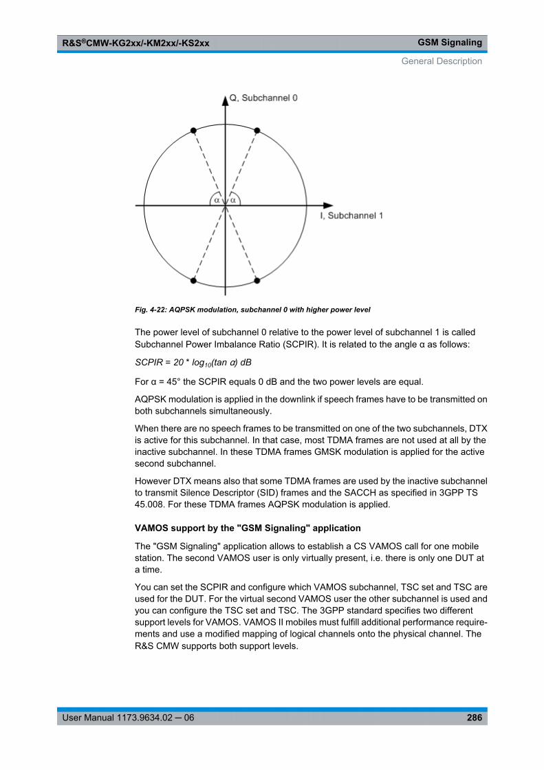
GSM SignalingR&S®CMW-KG2xx/-KM2xx/-KS2xx
286User Manual 1173.9634.02 ─ 06
Fig. 4-22: AQPSK modulation, subchannel 0 with higher power level
The power level of subchannel 0 relative to the power level of subchannel 1 is calledSubchannel Power Imbalance Ratio (SCPIR). It is related to the angle α as follows:
SCPIR = 20 * log10(tan α) dB
For α = 45° the SCPIR equals 0 dB and the two power levels are equal.
AQPSK modulation is applied in the downlink if speech frames have to be transmitted onboth subchannels simultaneously.
When there are no speech frames to be transmitted on one of the two subchannels, DTXis active for this subchannel. In that case, most TDMA frames are not used at all by theinactive subchannel. In these TDMA frames GMSK modulation is applied for the activesecond subchannel.
However DTX means also that some TDMA frames are used by the inactive subchannelto transmit Silence Descriptor (SID) frames and the SACCH as specified in 3GPP TS45.008. For these TDMA frames AQPSK modulation is applied.
VAMOS support by the "GSM Signaling" application
The "GSM Signaling" application allows to establish a CS VAMOS call for one mobilestation. The second VAMOS user is only virtually present, i.e. there is only one DUT ata time.
You can set the SCPIR and configure which VAMOS subchannel, TSC set and TSC areused for the DUT. For the virtual second VAMOS user the other subchannel is used andyou can configure the TSC set and TSC. The 3GPP standard specifies two differentsupport levels for VAMOS. VAMOS II mobiles must fulfill additional performance require-ments and use a modified mapping of logical channels onto the physical channel. TheR&S CMW supports both support levels.
General Description
GSM SignalingR&S®CMW-KG2xx/-KM2xx/-KS2xx
287User Manual 1173.9634.02 ─ 06
Other downlink properties depend on the selected profile. Three profiles are available:● Single User: There is no second VAMOS user at all. The downlink signal contains
speech frames and signaling data for the DUT only. GMSK modulation is used.The main difference to disabled VAMOS is that the VAMOS specific training sequen-ces can be applied (TSC set 2).
● Two users, both active: The downlink signal contains speech frames and signalingdata for both users. AQPSK modulation is applied.For the virtual user PRBS 2E9-1 is sent as data and no channel coding is applied.For the subchannel used by the DUT the same data source (e.g. Echo) as withoutVAMOS is selected. This applies to all profiles.
● Two users, only one active: The downlink signal contains speech frames for theDUT only. For the virtual user DTX is transmitted. Depending on the TDMA framenumber either GMSK modulation (virtual user transmits nothing) or AQPSK modula-tion (virtual user transmits SID or SACCH) is applied.
For configuration of VAMOS see chapter 4.4.8.1, "Circuit Switched General Parame-ters", on page 333.
4.3 Application Sheets
Application sheets describe short application examples for select issues and providerelated background information. The following application sheets are related to the "GSMSignaling" firmware application.
● GSM Combined Signal Path Measurements........................................................287● Handover from WCDMA to GSM..........................................................................291
4.3.1 GSM Combined Signal Path Measurements
This application sheet describes how to establish a Circuit Switched (CS) connection toa GSM Mobile Station (MS) and perform TX measurements on the received uplink signal.
Sequencer tool R&S CMWrunThe automated test capabilities of R&S CMWrun make many measurement tasks easier.Option R&S CMW-KT053 provides configurable GSM and WCDMA test modules andtest plans for R&S CMWrun.
4.3.1.1 Options and Equipment Required
A GSM combined signal path measurement requires the following equipment:● Wideband Radio Communication Tester R&S CMW500 or R&S CMW280 with soft-
ware version ≥ V1.0.15.20. The latest software version is recommended.● Option R&S CMW-KS200, "GSM Signaling" application (GSM R6 basic signaling)
Application Sheets
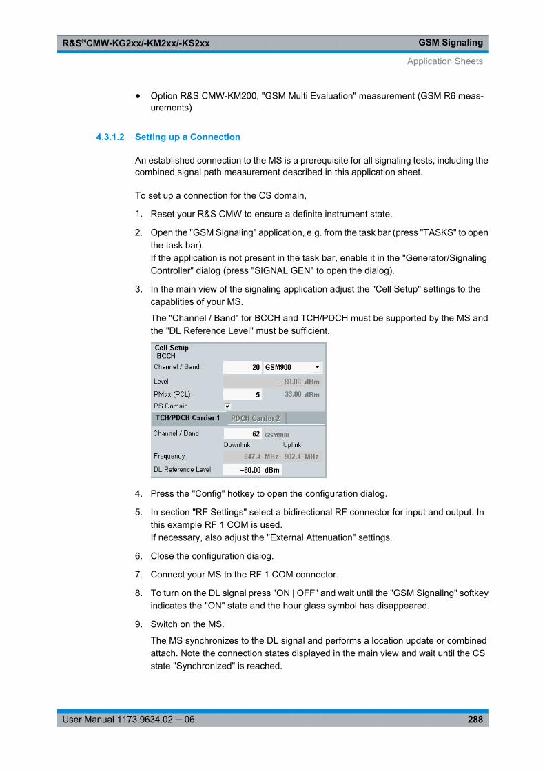
GSM SignalingR&S®CMW-KG2xx/-KM2xx/-KS2xx
288User Manual 1173.9634.02 ─ 06
● Option R&S CMW-KM200, "GSM Multi Evaluation" measurement (GSM R6 meas-urements)
4.3.1.2 Setting up a Connection
An established connection to the MS is a prerequisite for all signaling tests, including thecombined signal path measurement described in this application sheet.
To set up a connection for the CS domain,
1. Reset your R&S CMW to ensure a definite instrument state.
2. Open the "GSM Signaling" application, e.g. from the task bar (press "TASKS" to openthe task bar).If the application is not present in the task bar, enable it in the "Generator/SignalingController" dialog (press "SIGNAL GEN" to open the dialog).
3. In the main view of the signaling application adjust the "Cell Setup" settings to thecapablities of your MS.
The "Channel / Band" for BCCH and TCH/PDCH must be supported by the MS andthe "DL Reference Level" must be sufficient.
4. Press the "Config" hotkey to open the configuration dialog.
5. In section "RF Settings" select a bidirectional RF connector for input and output. Inthis example RF 1 COM is used.If necessary, also adjust the "External Attenuation" settings.
6. Close the configuration dialog.
7. Connect your MS to the RF 1 COM connector.
8. To turn on the DL signal press "ON | OFF" and wait until the "GSM Signaling" softkeyindicates the "ON" state and the hour glass symbol has disappeared.
9. Switch on the MS.
The MS synchronizes to the DL signal and performs a location update or combinedattach. Note the connection states displayed in the main view and wait until the CSstate "Synchronized" is reached.
Application Sheets
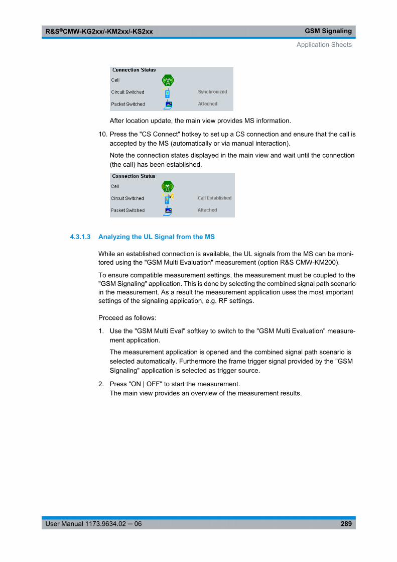
GSM SignalingR&S®CMW-KG2xx/-KM2xx/-KS2xx
289User Manual 1173.9634.02 ─ 06
After location update, the main view provides MS information.
10. Press the "CS Connect" hotkey to set up a CS connection and ensure that the call isaccepted by the MS (automatically or via manual interaction).
Note the connection states displayed in the main view and wait until the connection(the call) has been established.
4.3.1.3 Analyzing the UL Signal from the MS
While an established connection is available, the UL signals from the MS can be moni-tored using the "GSM Multi Evaluation" measurement (option R&S CMW-KM200).
To ensure compatible measurement settings, the measurement must be coupled to the"GSM Signaling" application. This is done by selecting the combined signal path scenarioin the measurement. As a result the measurement application uses the most importantsettings of the signaling application, e.g. RF settings.
Proceed as follows:
1. Use the "GSM Multi Eval" softkey to switch to the "GSM Multi Evaluation" measure-ment application.
The measurement application is opened and the combined signal path scenario isselected automatically. Furthermore the frame trigger signal provided by the "GSMSignaling" application is selected as trigger source.
2. Press "ON | OFF" to start the measurement.The main view provides an overview of the measurement results.
Application Sheets
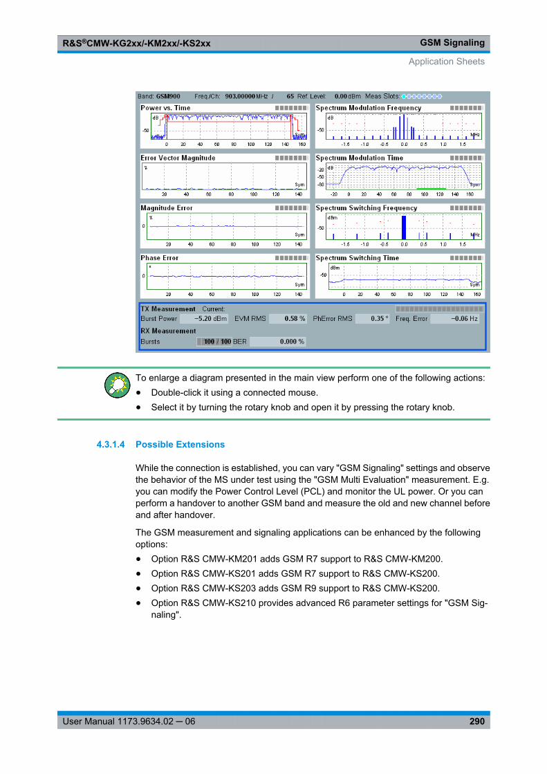
GSM SignalingR&S®CMW-KG2xx/-KM2xx/-KS2xx
290User Manual 1173.9634.02 ─ 06
To enlarge a diagram presented in the main view perform one of the following actions:● Double-click it using a connected mouse.● Select it by turning the rotary knob and open it by pressing the rotary knob.
4.3.1.4 Possible Extensions
While the connection is established, you can vary "GSM Signaling" settings and observethe behavior of the MS under test using the "GSM Multi Evaluation" measurement. E.g.you can modify the Power Control Level (PCL) and monitor the UL power. Or you canperform a handover to another GSM band and measure the old and new channel beforeand after handover.
The GSM measurement and signaling applications can be enhanced by the followingoptions:● Option R&S CMW-KM201 adds GSM R7 support to R&S CMW-KM200.● Option R&S CMW-KS201 adds GSM R7 support to R&S CMW-KS200.● Option R&S CMW-KS203 adds GSM R9 support to R&S CMW-KS200.● Option R&S CMW-KS210 provides advanced R6 parameter settings for "GSM Sig-
naling".
Application Sheets
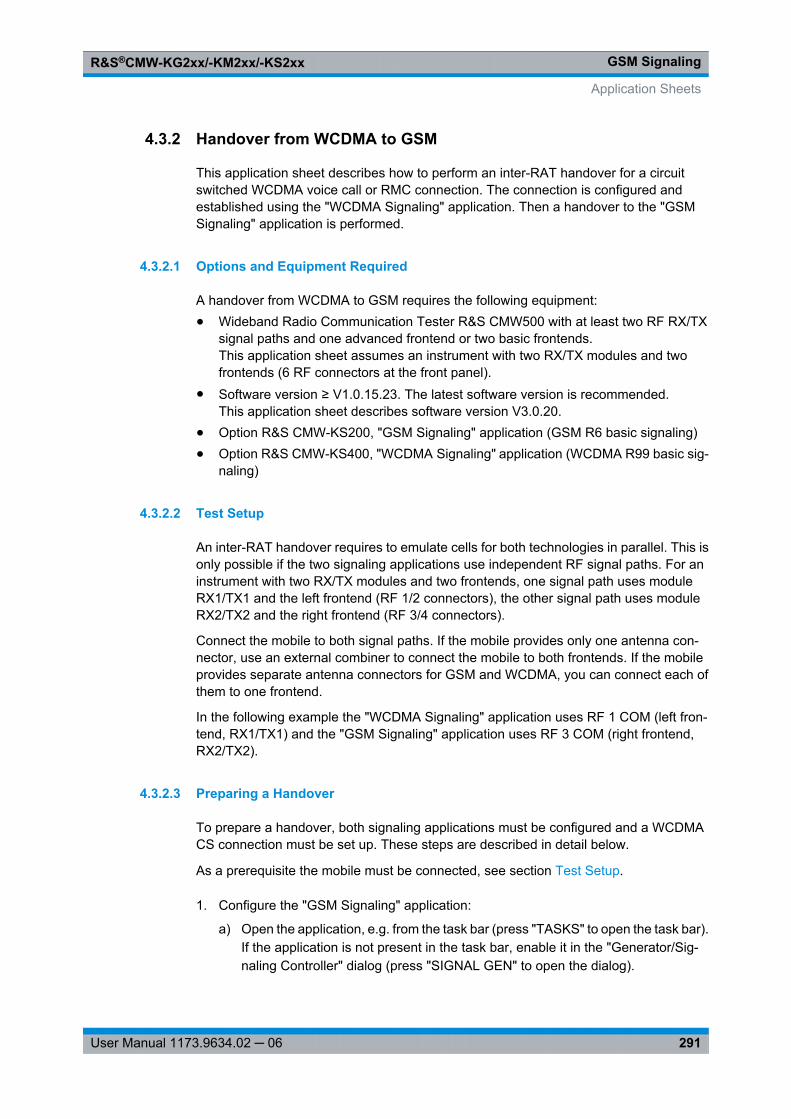
GSM SignalingR&S®CMW-KG2xx/-KM2xx/-KS2xx
291User Manual 1173.9634.02 ─ 06
4.3.2 Handover from WCDMA to GSM
This application sheet describes how to perform an inter-RAT handover for a circuitswitched WCDMA voice call or RMC connection. The connection is configured andestablished using the "WCDMA Signaling" application. Then a handover to the "GSMSignaling" application is performed.
4.3.2.1 Options and Equipment Required
A handover from WCDMA to GSM requires the following equipment:● Wideband Radio Communication Tester R&S CMW500 with at least two RF RX/TX
signal paths and one advanced frontend or two basic frontends.This application sheet assumes an instrument with two RX/TX modules and twofrontends (6 RF connectors at the front panel).
● Software version ≥ V1.0.15.23. The latest software version is recommended.This application sheet describes software version V3.0.20.
● Option R&S CMW-KS200, "GSM Signaling" application (GSM R6 basic signaling)● Option R&S CMW-KS400, "WCDMA Signaling" application (WCDMA R99 basic sig-
naling)
4.3.2.2 Test Setup
An inter-RAT handover requires to emulate cells for both technologies in parallel. This isonly possible if the two signaling applications use independent RF signal paths. For aninstrument with two RX/TX modules and two frontends, one signal path uses moduleRX1/TX1 and the left frontend (RF 1/2 connectors), the other signal path uses moduleRX2/TX2 and the right frontend (RF 3/4 connectors).
Connect the mobile to both signal paths. If the mobile provides only one antenna con-nector, use an external combiner to connect the mobile to both frontends. If the mobileprovides separate antenna connectors for GSM and WCDMA, you can connect each ofthem to one frontend.
In the following example the "WCDMA Signaling" application uses RF 1 COM (left fron-tend, RX1/TX1) and the "GSM Signaling" application uses RF 3 COM (right frontend,RX2/TX2).
4.3.2.3 Preparing a Handover
To prepare a handover, both signaling applications must be configured and a WCDMACS connection must be set up. These steps are described in detail below.
As a prerequisite the mobile must be connected, see section Test Setup.
1. Configure the "GSM Signaling" application:
a) Open the application, e.g. from the task bar (press "TASKS" to open the task bar).If the application is not present in the task bar, enable it in the "Generator/Sig-naling Controller" dialog (press "SIGNAL GEN" to open the dialog).
Application Sheets
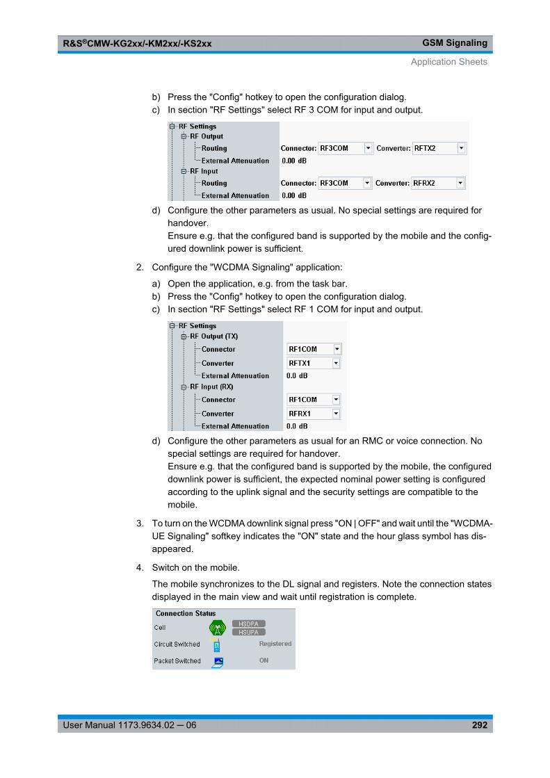
GSM SignalingR&S®CMW-KG2xx/-KM2xx/-KS2xx
292User Manual 1173.9634.02 ─ 06
b) Press the "Config" hotkey to open the configuration dialog.c) In section "RF Settings" select RF 3 COM for input and output.
d) Configure the other parameters as usual. No special settings are required forhandover.Ensure e.g. that the configured band is supported by the mobile and the config-ured downlink power is sufficient.
2. Configure the "WCDMA Signaling" application:
a) Open the application, e.g. from the task bar.b) Press the "Config" hotkey to open the configuration dialog.c) In section "RF Settings" select RF 1 COM for input and output.
d) Configure the other parameters as usual for an RMC or voice connection. Nospecial settings are required for handover.Ensure e.g. that the configured band is supported by the mobile, the configureddownlink power is sufficient, the expected nominal power setting is configuredaccording to the uplink signal and the security settings are compatible to themobile.
3. To turn on the WCDMA downlink signal press "ON | OFF" and wait until the "WCDMA-UE Signaling" softkey indicates the "ON" state and the hour glass symbol has dis-appeared.
4. Switch on the mobile.
The mobile synchronizes to the DL signal and registers. Note the connection statesdisplayed in the main view and wait until registration is complete.
Application Sheets
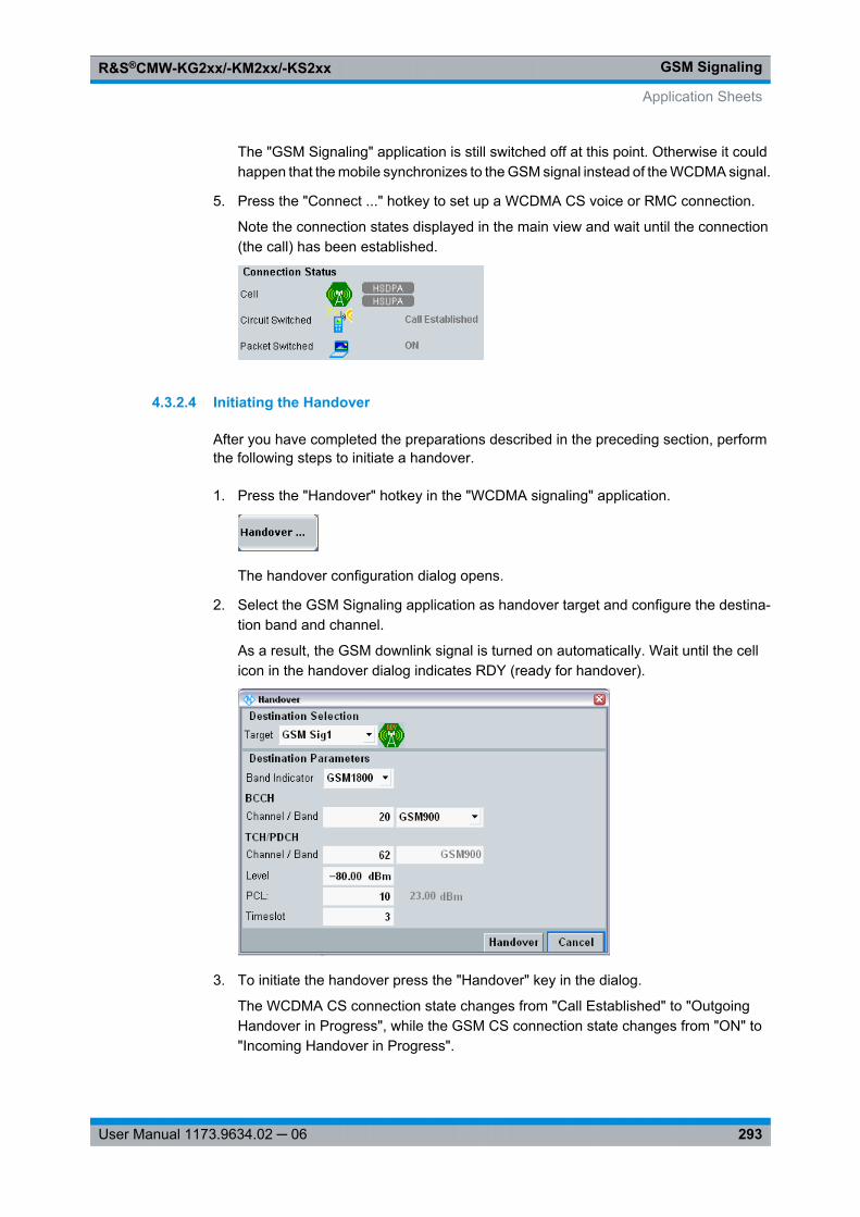
GSM SignalingR&S®CMW-KG2xx/-KM2xx/-KS2xx
293User Manual 1173.9634.02 ─ 06
The "GSM Signaling" application is still switched off at this point. Otherwise it couldhappen that the mobile synchronizes to the GSM signal instead of the WCDMA signal.
5. Press the "Connect ..." hotkey to set up a WCDMA CS voice or RMC connection.
Note the connection states displayed in the main view and wait until the connection(the call) has been established.
4.3.2.4 Initiating the Handover
After you have completed the preparations described in the preceding section, performthe following steps to initiate a handover.
1. Press the "Handover" hotkey in the "WCDMA signaling" application.
The handover configuration dialog opens.
2. Select the GSM Signaling application as handover target and configure the destina-tion band and channel.
As a result, the GSM downlink signal is turned on automatically. Wait until the cellicon in the handover dialog indicates RDY (ready for handover).
3. To initiate the handover press the "Handover" key in the dialog.
The WCDMA CS connection state changes from "Call Established" to "OutgoingHandover in Progress", while the GSM CS connection state changes from "ON" to"Incoming Handover in Progress".
Application Sheets
GSM SignalingR&S®CMW-KG2xx/-KM2xx/-KS2xx
294User Manual 1173.9634.02 ─ 06
When the handover has been completed, the WCDMA CS state changes to "ON",the GSM CS state to "Call Established" and the GSM cell state to "ON".
4.4 GUI Reference
The following sections provide detailed reference information on the parameters of theGSM signaling application (option R&S CMW-KS200). Most of the signaling parametersare arranged in the "GSM Signaling Configuration" dialog. Additional dialogs allow toconfigure the measurements included in the signaling application.
Many of the signaling parameters are available in a subset of connection states only (e.g.handover is only possible when a circuit switched connection is established). Temporarilyunavailable parameters are grayed out in the configuration dialogs; softkeys and hotkeysappear and disappear dynamically, depending on the connection state.
The screenshots in this chapter show the GUI with all available options installed. Depend-ing on the installed options some parameters may not be configurable (display the defaultvalue) or may be hidden completely. To show such hidden parameters see chap-ter 4.4.12, "Show Features at Inactive SW Licenses", on page 345.The following options are indicated in the parameter descriptions if they are required inaddition to R&S CMW-KS200:● R&S CMW-KS201, GSM Release 7 signaling basic functionality● R&S CMW-KS203, GSM Release 9 signaling basic functionality● R&S CMW-KS210, GSM Release 6 signaling advanced functionality
The "GSM Signaling" application is configured using the following groups of settings:
● Signaling View.......................................................................................................295● Signaling and Connection Control.........................................................................308● General Settings...................................................................................................311● I/Q Settings...........................................................................................................312● RF Settings...........................................................................................................314● Internal Fading......................................................................................................321● Network Parameters.............................................................................................324● Connection Parameters........................................................................................332● Trigger Signal Settings..........................................................................................343● Messaging (SMS) Parameters..............................................................................343● Measurement Connection Parameters.................................................................344● Show Features at Inactive SW Licenses...............................................................345● Using the Shortcut Softkeys..................................................................................345● BER CS Measurement..........................................................................................346● BER PS Measurement..........................................................................................350● BLER Measurement..............................................................................................354
GUI Reference
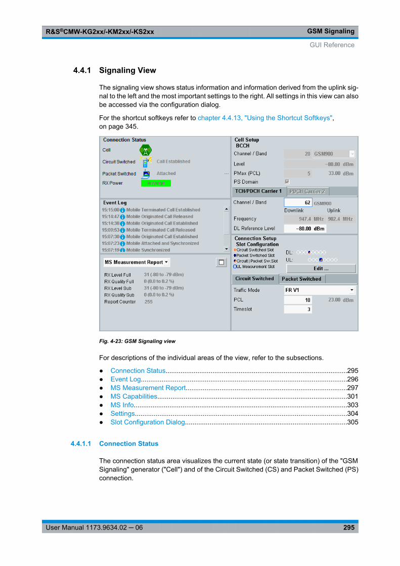
GSM SignalingR&S®CMW-KG2xx/-KM2xx/-KS2xx
295User Manual 1173.9634.02 ─ 06
4.4.1 Signaling View
The signaling view shows status information and information derived from the uplink sig-nal to the left and the most important settings to the right. All settings in this view can alsobe accessed via the configuration dialog.
For the shortcut softkeys refer to chapter 4.4.13, "Using the Shortcut Softkeys",on page 345.
Fig. 4-23: GSM Signaling view
For descriptions of the individual areas of the view, refer to the subsections.
● Connection Status.................................................................................................295● Event Log..............................................................................................................296● MS Measurement Report......................................................................................297● MS Capabilities.....................................................................................................301● MS Info..................................................................................................................303● Settings.................................................................................................................304● Slot Configuration Dialog......................................................................................305
4.4.1.1 Connection Status
The connection status area visualizes the current state (or state transition) of the "GSMSignaling" generator ("Cell") and of the Circuit Switched (CS) and Packet Switched (PS)connection.
GUI Reference
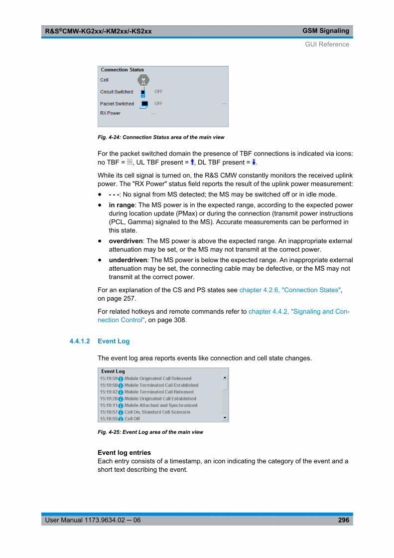
GSM SignalingR&S®CMW-KG2xx/-KM2xx/-KS2xx
296User Manual 1173.9634.02 ─ 06
Fig. 4-24: Connection Status area of the main view
For the packet switched domain the presence of TBF connections is indicated via icons:no TBF = , UL TBF present = , DL TBF present = .
While its cell signal is turned on, the R&S CMW constantly monitors the received uplinkpower. The "RX Power" status field reports the result of the uplink power measurement:● - - -: No signal from MS detected; the MS may be switched off or in idle mode.● in range: The MS power is in the expected range, according to the expected power
during location update (PMax) or during the connection (transmit power instructions(PCL, Gamma) signaled to the MS). Accurate measurements can be performed inthis state.
● overdriven: The MS power is above the expected range. An inappropriate externalattenuation may be set, or the MS may not transmit at the correct power.
● underdriven: The MS power is below the expected range. An inappropriate externalattenuation may be set, the connecting cable may be defective, or the MS may nottransmit at the correct power.
For an explanation of the CS and PS states see chapter 4.2.6, "Connection States",on page 257.
For related hotkeys and remote commands refer to chapter 4.4.2, "Signaling and Con-nection Control", on page 308.
4.4.1.2 Event Log
The event log area reports events like connection and cell state changes.
Fig. 4-25: Event Log area of the main view
Event log entriesEach entry consists of a timestamp, an icon indicating the category of the event and ashort text describing the event.
GUI Reference
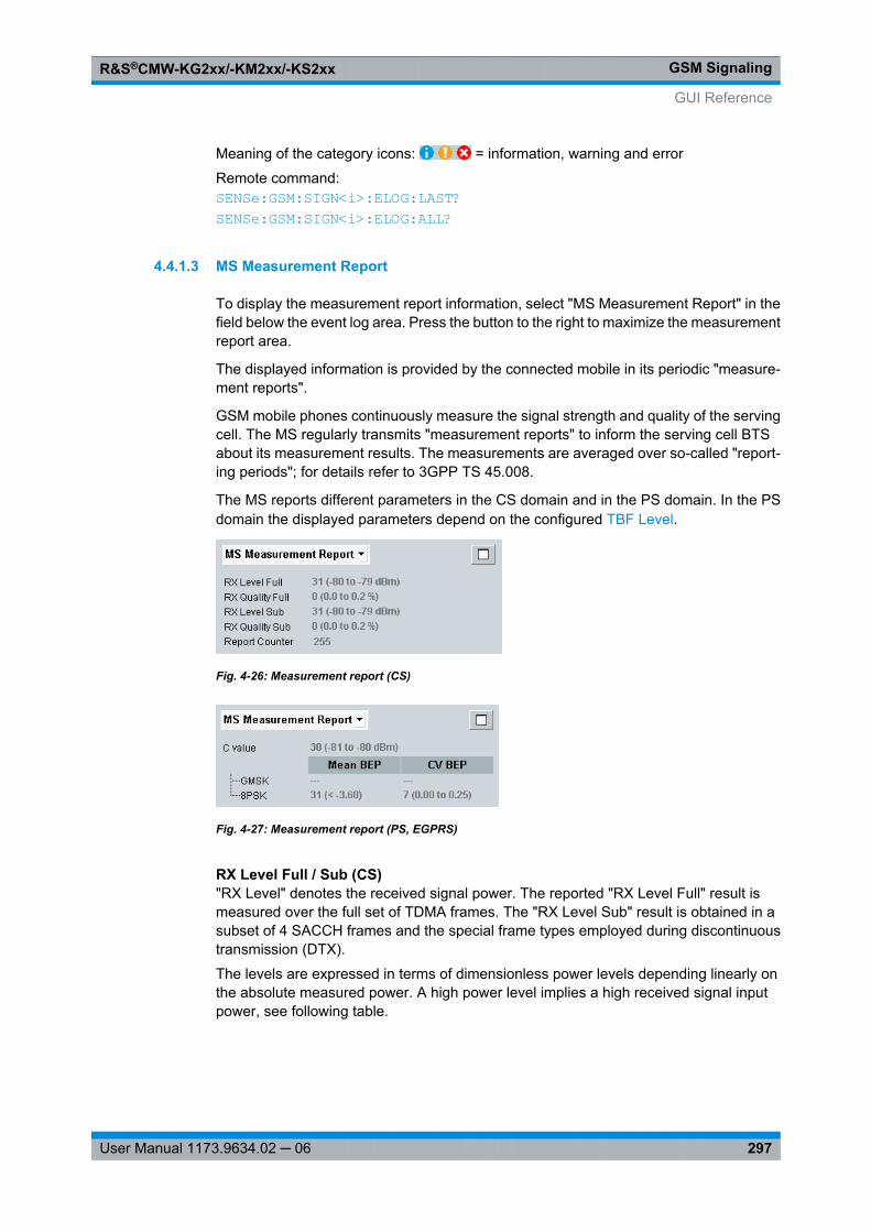
GSM SignalingR&S®CMW-KG2xx/-KM2xx/-KS2xx
297User Manual 1173.9634.02 ─ 06
Meaning of the category icons: = information, warning and error
Remote command: SENSe: GSM: SIGN<i>: ELOG: LAST? SENSe: GSM: SIGN<i>: ELOG: ALL?
4.4.1.3 MS Measurement Report
To display the measurement report information, select "MS Measurement Report" in thefield below the event log area. Press the button to the right to maximize the measurementreport area.
The displayed information is provided by the connected mobile in its periodic "measure-ment reports".
GSM mobile phones continuously measure the signal strength and quality of the servingcell. The MS regularly transmits "measurement reports" to inform the serving cell BTSabout its measurement results. The measurements are averaged over so-called "report-ing periods"; for details refer to 3GPP TS 45.008.
The MS reports different parameters in the CS domain and in the PS domain. In the PSdomain the displayed parameters depend on the configured TBF Level.
Fig. 4-26: Measurement report (CS)
Fig. 4-27: Measurement report (PS, EGPRS)
RX Level Full / Sub (CS)"RX Level" denotes the received signal power. The reported "RX Level Full" result ismeasured over the full set of TDMA frames. The "RX Level Sub" result is obtained in asubset of 4 SACCH frames and the special frame types employed during discontinuoustransmission (DTX).
The levels are expressed in terms of dimensionless power levels depending linearly onthe absolute measured power. A high power level implies a high received signal inputpower, see following table.
GUI Reference
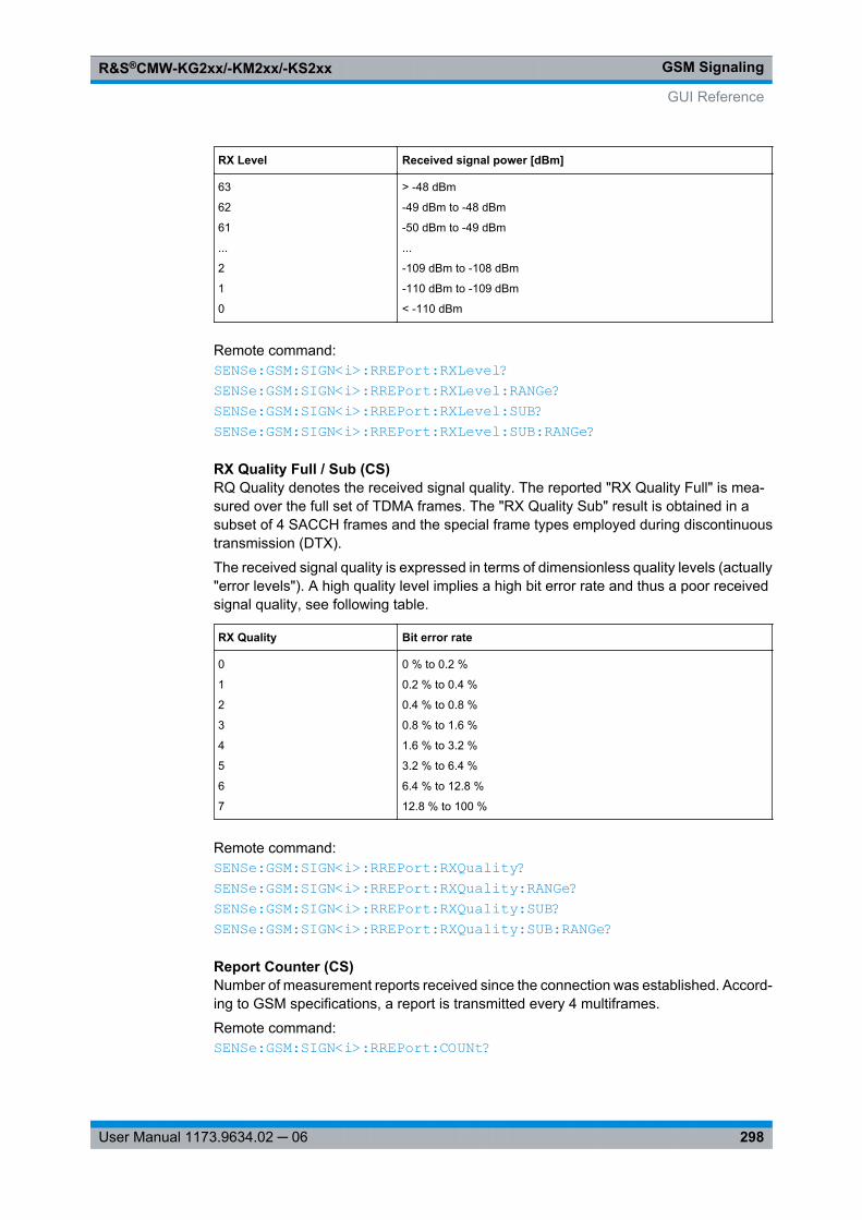
GSM SignalingR&S®CMW-KG2xx/-KM2xx/-KS2xx
298User Manual 1173.9634.02 ─ 06
RX Level Received signal power [dBm]
63
62
61
...
2
1
0
> -48 dBm
-49 dBm to -48 dBm
-50 dBm to -49 dBm
...
-109 dBm to -108 dBm
-110 dBm to -109 dBm
< -110 dBm
Remote command: SENSe: GSM: SIGN<i>: RREPort: RXLevel? SENSe: GSM: SIGN<i>: RREPort: RXLevel: RANGe? SENSe: GSM: SIGN<i>: RREPort: RXLevel: SUB? SENSe: GSM: SIGN<i>: RREPort: RXLevel: SUB: RANGe?
RX Quality Full / Sub (CS)RQ Quality denotes the received signal quality. The reported "RX Quality Full" is mea-sured over the full set of TDMA frames. The "RX Quality Sub" result is obtained in asubset of 4 SACCH frames and the special frame types employed during discontinuoustransmission (DTX).
The received signal quality is expressed in terms of dimensionless quality levels (actually"error levels"). A high quality level implies a high bit error rate and thus a poor receivedsignal quality, see following table.
RX Quality Bit error rate
0
1
2
3
4
5
6
7
0 % to 0.2 %
0.2 % to 0.4 %
0.4 % to 0.8 %
0.8 % to 1.6 %
1.6 % to 3.2 %
3.2 % to 6.4 %
6.4 % to 12.8 %
12.8 % to 100 %
Remote command: SENSe: GSM: SIGN<i>: RREPort: RXQuality? SENSe: GSM: SIGN<i>: RREPort: RXQuality: RANGe? SENSe: GSM: SIGN<i>: RREPort: RXQuality: SUB? SENSe: GSM: SIGN<i>: RREPort: RXQuality: SUB: RANGe?
Report Counter (CS)Number of measurement reports received since the connection was established. Accord-ing to GSM specifications, a report is transmitted every 4 multiframes.
Remote command: SENSe: GSM: SIGN<i>: RREPort: COUNt?
GUI Reference
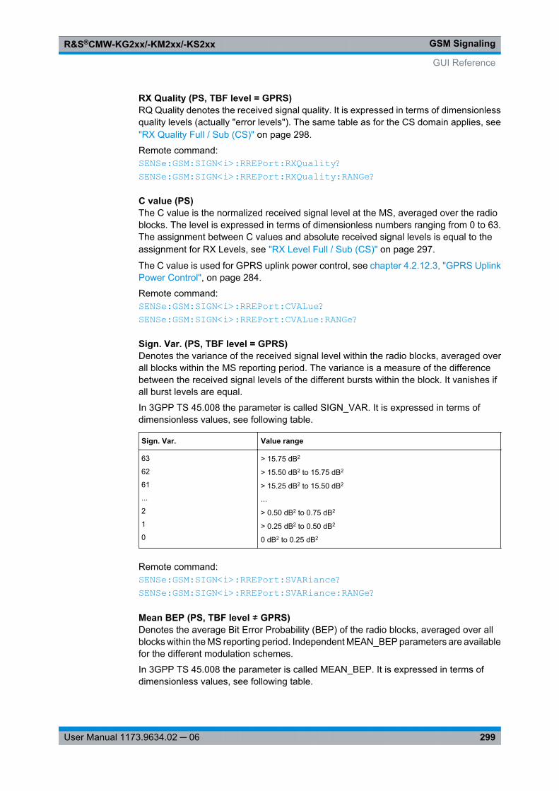
GSM SignalingR&S®CMW-KG2xx/-KM2xx/-KS2xx
299User Manual 1173.9634.02 ─ 06
RX Quality (PS, TBF level = GPRS)RQ Quality denotes the received signal quality. It is expressed in terms of dimensionlessquality levels (actually "error levels"). The same table as for the CS domain applies, see"RX Quality Full / Sub (CS)" on page 298.
Remote command: SENSe: GSM: SIGN<i>: RREPort: RXQuality? SENSe: GSM: SIGN<i>: RREPort: RXQuality: RANGe?
C value (PS)The C value is the normalized received signal level at the MS, averaged over the radioblocks. The level is expressed in terms of dimensionless numbers ranging from 0 to 63.The assignment between C values and absolute received signal levels is equal to theassignment for RX Levels, see "RX Level Full / Sub (CS)" on page 297.
The C value is used for GPRS uplink power control, see chapter 4.2.12.3, "GPRS UplinkPower Control", on page 284.
Remote command: SENSe: GSM: SIGN<i>: RREPort: CVALue? SENSe: GSM: SIGN<i>: RREPort: CVALue: RANGe?
Sign. Var. (PS, TBF level = GPRS)Denotes the variance of the received signal level within the radio blocks, averaged overall blocks within the MS reporting period. The variance is a measure of the differencebetween the received signal levels of the different bursts within the block. It vanishes ifall burst levels are equal.
In 3GPP TS 45.008 the parameter is called SIGN_VAR. It is expressed in terms ofdimensionless values, see following table.
Sign. Var. Value range
63
62
61
...
2
1
0
> 15.75 dB2
> 15.50 dB2 to 15.75 dB2
> 15.25 dB2 to 15.50 dB2
...
> 0.50 dB2 to 0.75 dB2
> 0.25 dB2 to 0.50 dB2
0 dB2 to 0.25 dB2
Remote command: SENSe: GSM: SIGN<i>: RREPort: SVARiance? SENSe: GSM: SIGN<i>: RREPort: SVARiance: RANGe?
Mean BEP (PS, TBF level ≠ GPRS)Denotes the average Bit Error Probability (BEP) of the radio blocks, averaged over allblocks within the MS reporting period. Independent MEAN_BEP parameters are availablefor the different modulation schemes.
In 3GPP TS 45.008 the parameter is called MEAN_BEP. It is expressed in terms ofdimensionless values, see following table.
GUI Reference
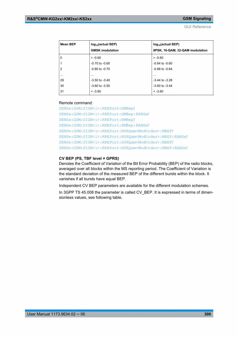
GSM SignalingR&S®CMW-KG2xx/-KM2xx/-KS2xx
300User Manual 1173.9634.02 ─ 06
Mean BEP log10(actual BEP)
GMSK modulation
log10(actual BEP)
8PSK, 16-QAM, 32-QAM modulation
0
1
2
...
29
30
31
> -0.60
-0.70 to -0.60
-0.80 to -0.70
...
-3.50 to -3.40
-3.60 to -3.50
< -3.60
> -0.60
-0.64 to -0.60
-0.68 to -0.64
...
-3.44 to -3.28
-3.60 to -3.44
< -3.60
Remote command: SENSe: GSM: SIGN<i>: RREPort: GMBep? SENSe: GSM: SIGN<i>: RREPort: GMBep: RANGe? SENSe: GSM: SIGN<i>: RREPort: EMBep? SENSe: GSM: SIGN<i>: RREPort: EMBep: RANGe? SENSe: GSM: SIGN<i>: RREPort: NSRQam<ModOrder>: MBEP? SENSe: GSM: SIGN<i>: RREPort: NSRQam<ModOrder>: MBEP: RANGe? SENSe: GSM: SIGN<i>: RREPort: HSRQam<ModOrder>: MBEP? SENSe: GSM: SIGN<i>: RREPort: HSRQam<ModOrder>: MBEP: RANGe?
CV BEP (PS, TBF level ≠ GPRS)Denotes the Coefficient of Variation of the Bit Error Probability (BEP) of the radio blocks,averaged over all blocks within the MS reporting period. The Coefficient of Variation isthe standard deviation of the measured BEP of the different bursts within the block. Itvanishes if all bursts have equal BEP.
Independent CV BEP parameters are available for the different modulation schemes.
In 3GPP TS 45.008 the parameter is called CV_BEP. It is expressed in terms of dimen-sionless values, see following table.
GUI Reference
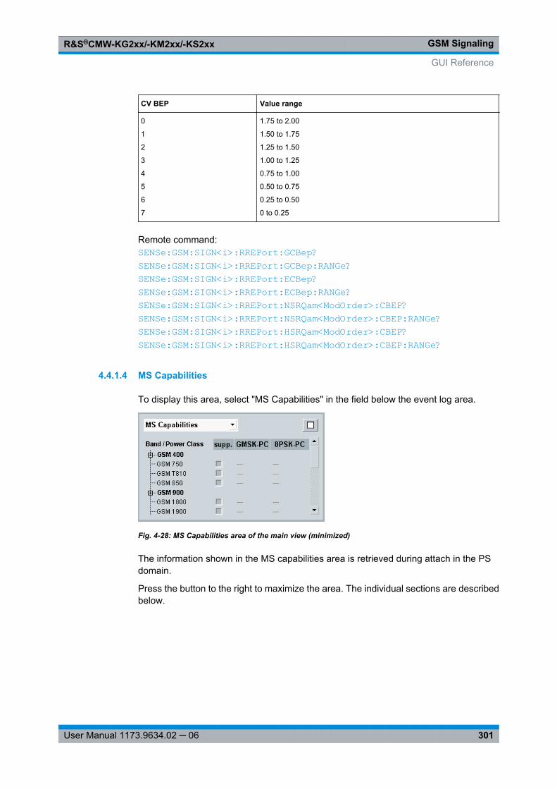
GSM SignalingR&S®CMW-KG2xx/-KM2xx/-KS2xx
301User Manual 1173.9634.02 ─ 06
CV BEP Value range
0
1
2
3
4
5
6
7
1.75 to 2.00
1.50 to 1.75
1.25 to 1.50
1.00 to 1.25
0.75 to 1.00
0.50 to 0.75
0.25 to 0.50
0 to 0.25
Remote command: SENSe: GSM: SIGN<i>: RREPort: GCBep? SENSe: GSM: SIGN<i>: RREPort: GCBep: RANGe? SENSe: GSM: SIGN<i>: RREPort: ECBep? SENSe: GSM: SIGN<i>: RREPort: ECBep: RANGe? SENSe: GSM: SIGN<i>: RREPort: NSRQam<ModOrder>: CBEP? SENSe: GSM: SIGN<i>: RREPort: NSRQam<ModOrder>: CBEP: RANGe? SENSe: GSM: SIGN<i>: RREPort: HSRQam<ModOrder>: CBEP? SENSe: GSM: SIGN<i>: RREPort: HSRQam<ModOrder>: CBEP: RANGe?
4.4.1.4 MS Capabilities
To display this area, select "MS Capabilities" in the field below the event log area.
Fig. 4-28: MS Capabilities area of the main view (minimized)
The information shown in the MS capabilities area is retrieved during attach in the PSdomain.
Press the button to the right to maximize the area. The individual sections are describedbelow.
GUI Reference
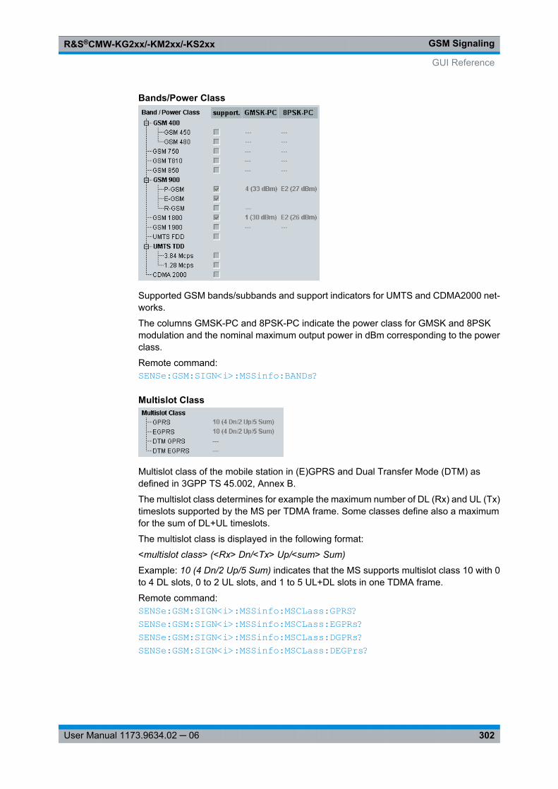
GSM SignalingR&S®CMW-KG2xx/-KM2xx/-KS2xx
302User Manual 1173.9634.02 ─ 06
Bands/Power Class
Supported GSM bands/subbands and support indicators for UMTS and CDMA2000 net-works.
The columns GMSK-PC and 8PSK-PC indicate the power class for GMSK and 8PSKmodulation and the nominal maximum output power in dBm corresponding to the powerclass.
Remote command: SENSe: GSM: SIGN<i>: MSSinfo: BANDs?
Multislot Class
Multislot class of the mobile station in (E)GPRS and Dual Transfer Mode (DTM) asdefined in 3GPP TS 45.002, Annex B.
The multislot class determines for example the maximum number of DL (Rx) and UL (Tx)timeslots supported by the MS per TDMA frame. Some classes define also a maximumfor the sum of DL+UL timeslots.
The multislot class is displayed in the following format:
<multislot class> (<Rx> Dn/<Tx> Up/<sum> Sum)
Example: 10 (4 Dn/2 Up/5 Sum) indicates that the MS supports multislot class 10 with 0to 4 DL slots, 0 to 2 UL slots, and 1 to 5 UL+DL slots in one TDMA frame.
Remote command: SENSe: GSM: SIGN<i>: MSSinfo: MSCLass: GPRS? SENSe: GSM: SIGN<i>: MSSinfo: MSCLass: EGPRs? SENSe: GSM: SIGN<i>: MSSinfo: MSCLass: DGPRs? SENSe: GSM: SIGN<i>: MSSinfo: MSCLass: DEGPrs?
GUI Reference
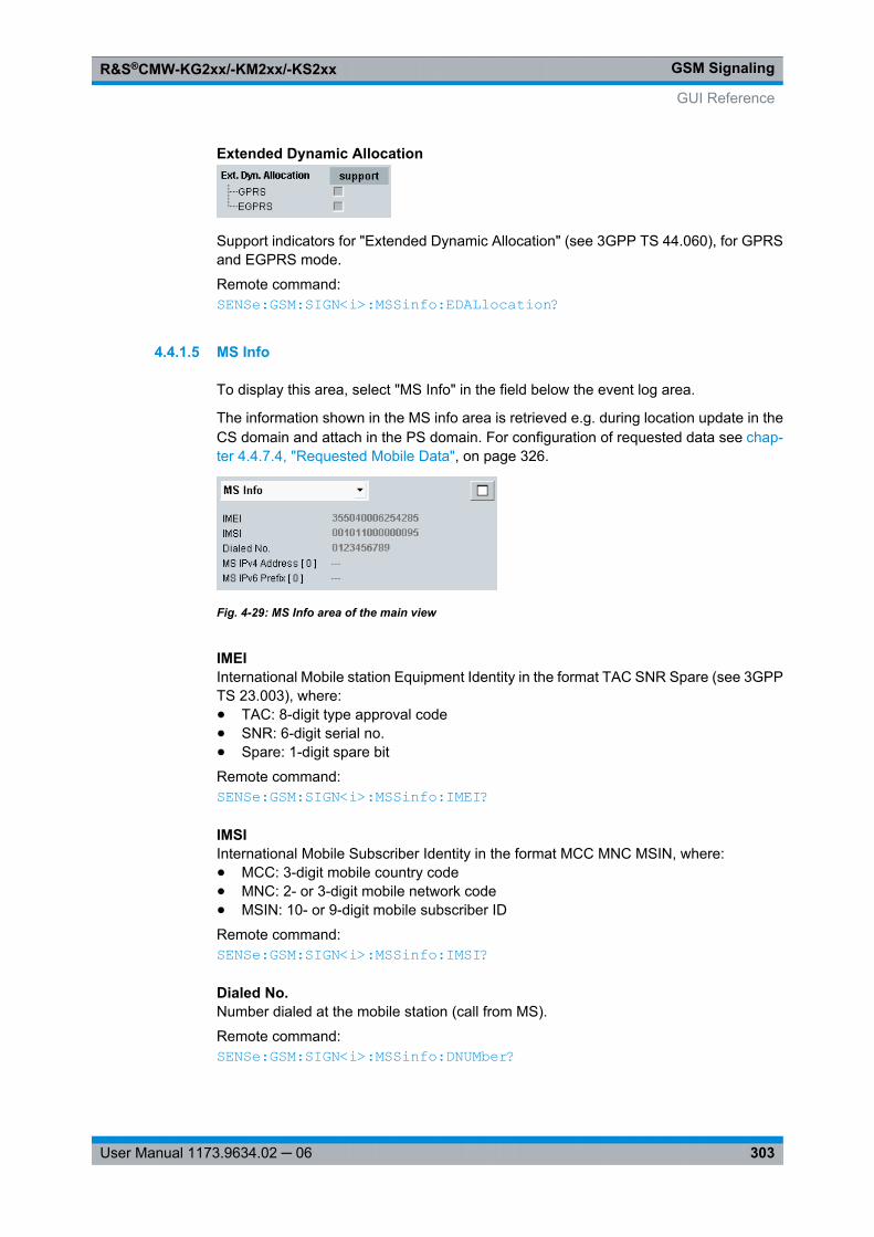
GSM SignalingR&S®CMW-KG2xx/-KM2xx/-KS2xx
303User Manual 1173.9634.02 ─ 06
Extended Dynamic Allocation
Support indicators for "Extended Dynamic Allocation" (see 3GPP TS 44.060), for GPRSand EGPRS mode.
Remote command: SENSe: GSM: SIGN<i>: MSSinfo: EDALlocation?
4.4.1.5 MS Info
To display this area, select "MS Info" in the field below the event log area.
The information shown in the MS info area is retrieved e.g. during location update in theCS domain and attach in the PS domain. For configuration of requested data see chap-ter 4.4.7.4, "Requested Mobile Data", on page 326.
Fig. 4-29: MS Info area of the main view
IMEIInternational Mobile station Equipment Identity in the format TAC SNR Spare (see 3GPPTS 23.003), where:● TAC: 8-digit type approval code● SNR: 6-digit serial no.● Spare: 1-digit spare bit
Remote command: SENSe: GSM: SIGN<i>: MSSinfo: IMEI?
IMSIInternational Mobile Subscriber Identity in the format MCC MNC MSIN, where:● MCC: 3-digit mobile country code● MNC: 2- or 3-digit mobile network code● MSIN: 10- or 9-digit mobile subscriber ID
Remote command: SENSe: GSM: SIGN<i>: MSSinfo: IMSI?
Dialed No.Number dialed at the mobile station (call from MS).
Remote command: SENSe: GSM: SIGN<i>: MSSinfo: DNUMber?
GUI Reference

GSM SignalingR&S®CMW-KG2xx/-KM2xx/-KS2xx
304User Manual 1173.9634.02 ─ 06
MS IPv4 Address / IPv6 PrefixDisplay the IPv4 address and/or the IPv6 prefix that have been assigned to the MS bythe R&S CMW.
The MS indicates whether it supports IPv4 only or IPv6 only or both. Depending on thisinformation the R&S CMW assigns either an IPv4 address or an IPv6 prefix or both anddisplays the assigned values.
Remote command: SENSe: GSM: SIGN<i>: MSSinfo: MSADdress: IPV<n>?
4.4.1.6 Settings
The main view provides the most important settings for fast access. Most parameters arealso available in the configuration dialog.
Fig. 4-30: Settings in the main view
Cell SetupThis section contains the most important BCCH and TCH/PDCH RF settings, see chap-ter 4.4.5, "RF Settings", on page 314. For the parameter "PS Domain" see "PacketSwitched Domain" on page 325.
Connection SetupDisplays a graphical presentation of the DL and UL slot configuration. Slots positioned inthe same row are time-aligned.
GUI Reference
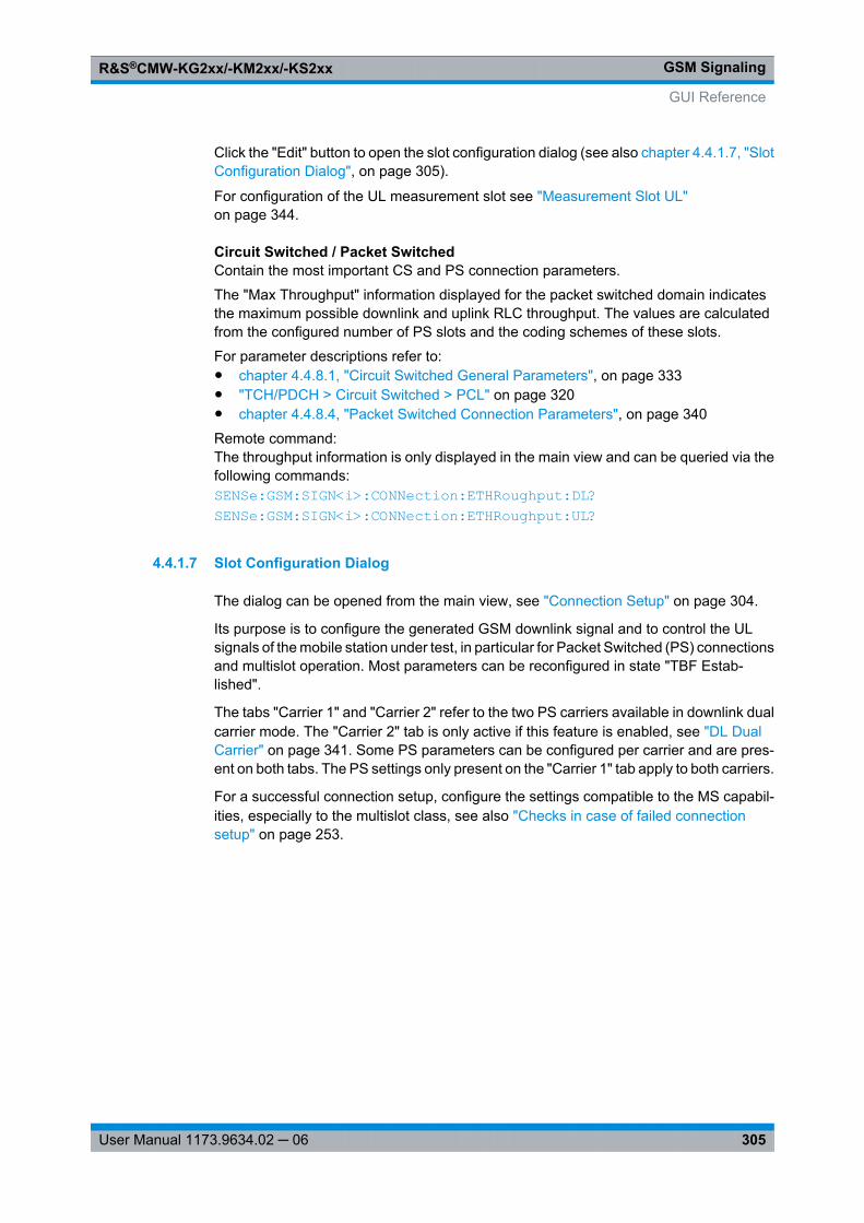
GSM SignalingR&S®CMW-KG2xx/-KM2xx/-KS2xx
305User Manual 1173.9634.02 ─ 06
Click the "Edit" button to open the slot configuration dialog (see also chapter 4.4.1.7, "SlotConfiguration Dialog", on page 305).
For configuration of the UL measurement slot see "Measurement Slot UL"on page 344.
Circuit Switched / Packet SwitchedContain the most important CS and PS connection parameters.
The "Max Throughput" information displayed for the packet switched domain indicatesthe maximum possible downlink and uplink RLC throughput. The values are calculatedfrom the configured number of PS slots and the coding schemes of these slots.
For parameter descriptions refer to:● chapter 4.4.8.1, "Circuit Switched General Parameters", on page 333● "TCH/PDCH > Circuit Switched > PCL" on page 320● chapter 4.4.8.4, "Packet Switched Connection Parameters", on page 340
Remote command: The throughput information is only displayed in the main view and can be queried via thefollowing commands:SENSe: GSM: SIGN<i>: CONNection: ETHRoughput: DL? SENSe: GSM: SIGN<i>: CONNection: ETHRoughput: UL?
4.4.1.7 Slot Configuration Dialog
The dialog can be opened from the main view, see "Connection Setup" on page 304.
Its purpose is to configure the generated GSM downlink signal and to control the ULsignals of the mobile station under test, in particular for Packet Switched (PS) connectionsand multislot operation. Most parameters can be reconfigured in state "TBF Estab-lished".
The tabs "Carrier 1" and "Carrier 2" refer to the two PS carriers available in downlink dualcarrier mode. The "Carrier 2" tab is only active if this feature is enabled, see "DL DualCarrier" on page 341. Some PS parameters can be configured per carrier and are pres-ent on both tabs. The PS settings only present on the "Carrier 1" tab apply to both carriers.
For a successful connection setup, configure the settings compatible to the MS capabil-ities, especially to the multislot class, see also "Checks in case of failed connectionsetup" on page 253.
GUI Reference
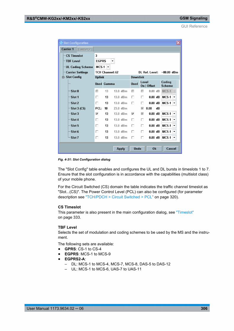
GSM SignalingR&S®CMW-KG2xx/-KM2xx/-KS2xx
306User Manual 1173.9634.02 ─ 06
Fig. 4-31: Slot Configuration dialog
The "Slot Config" table enables and configures the UL and DL bursts in timeslots 1 to 7.Ensure that the slot configuration is in accordance with the capabilities (multislot class)of your mobile phone.
For the Circuit Switched (CS) domain the table indicates the traffic channel timeslot as"Slot...(CS)". The Power Control Level (PCL) can also be configured (for parameterdescription see "TCH/PDCH > Circuit Switched > PCL" on page 320).
CS TimeslotThis parameter is also present in the main configuration dialog, see "Timeslot"on page 333.
TBF LevelSelects the set of modulation and coding schemes to be used by the MS and the instru-ment.
The following sets are available:● GPRS: CS-1 to CS-4● EGPRS: MCS-1 to MCS-9● EGPRS2-A:
– DL: MCS-1 to MCS-4, MCS-7, MCS-8, DAS-5 to DAS-12– UL: MCS-1 to MCS-6, UAS-7 to UAS-11
GUI Reference
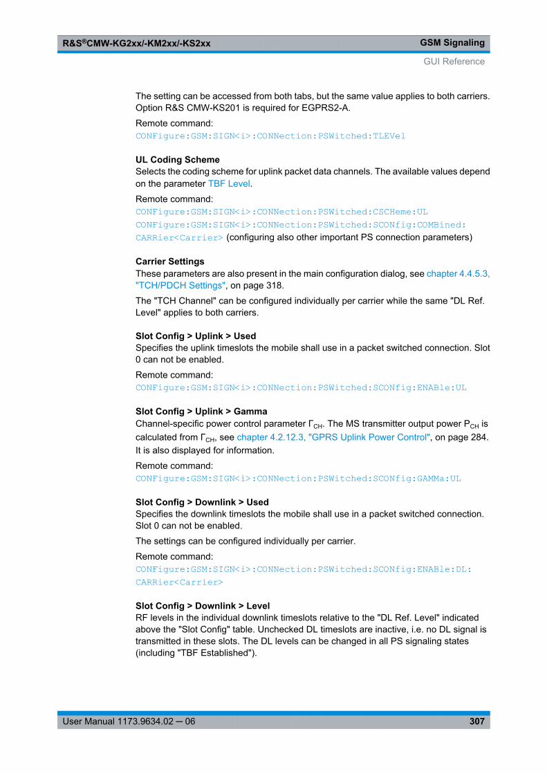
GSM SignalingR&S®CMW-KG2xx/-KM2xx/-KS2xx
307User Manual 1173.9634.02 ─ 06
The setting can be accessed from both tabs, but the same value applies to both carriers.Option R&S CMW-KS201 is required for EGPRS2-A.
Remote command: CONFigure: GSM: SIGN<i>: CONNection: PSWitched: TLEVel
UL Coding SchemeSelects the coding scheme for uplink packet data channels. The available values dependon the parameter TBF Level.
Remote command: CONFigure: GSM: SIGN<i>: CONNection: PSWitched: CSCHeme: UL CONFigure: GSM: SIGN<i>: CONNection: PSWitched: SCONfig: COMBined: CARRier<Carrier> (configuring also other important PS connection parameters)
Carrier SettingsThese parameters are also present in the main configuration dialog, see chapter 4.4.5.3,"TCH/PDCH Settings", on page 318.
The "TCH Channel" can be configured individually per carrier while the same "DL Ref.Level" applies to both carriers.
Slot Config > Uplink > UsedSpecifies the uplink timeslots the mobile shall use in a packet switched connection. Slot0 can not be enabled.
Remote command: CONFigure: GSM: SIGN<i>: CONNection: PSWitched: SCONfig: ENABle: UL
Slot Config > Uplink > GammaChannel-specific power control parameter ΓCH. The MS transmitter output power PCH iscalculated from ΓCH, see chapter 4.2.12.3, "GPRS Uplink Power Control", on page 284.It is also displayed for information.
Remote command: CONFigure: GSM: SIGN<i>: CONNection: PSWitched: SCONfig: GAMMa: UL
Slot Config > Downlink > UsedSpecifies the downlink timeslots the mobile shall use in a packet switched connection.Slot 0 can not be enabled.
The settings can be configured individually per carrier.
Remote command: CONFigure: GSM: SIGN<i>: CONNection: PSWitched: SCONfig: ENABle: DL: CARRier<Carrier>
Slot Config > Downlink > LevelRF levels in the individual downlink timeslots relative to the "DL Ref. Level" indicatedabove the "Slot Config" table. Unchecked DL timeslots are inactive, i.e. no DL signal istransmitted in these slots. The DL levels can be changed in all PS signaling states(including "TBF Established").
GUI Reference
GSM SignalingR&S®CMW-KG2xx/-KM2xx/-KS2xx
308User Manual 1173.9634.02 ─ 06
Option R&S CMW-KS210 is required for configuration.
Remote command: CONFigure: GSM: SIGN<i>: CONNection: PSWitched: SCONfig: LEVel: DL: CARRier<Carrier>
Slot Config > Downlink > Coding SchemeCoding schemes used for the individual downlink timeslots. The available values dependon the parameter TBF Level.
The setting can be accessed from both tabs, but the same value applies to both carriers.
Remote command: CONFigure: GSM: SIGN<i>: CONNection: PSWitched: SCONfig: CSCHeme: DL: CARRier<Carrier>
4.4.2 Signaling and Connection Control
The individual connection states are controlled via the ON | OFF key, via hotkeys and viathe MS.
The available hotkeys depend on the current connection state. Below all possible hotkeysare described.
For background information refer to chapter 4.2.6, "Connection States", on page 257.
ON | OFF (key) / GSM Signaling (softkey)The ON | OFF key is used to turn the DL signal transmission on or off. The current stateis shown by the softkey. The signal transmission can be switched off any time, inde-pendent of the current connection state. A yellow sandglass symbol indicates that thesignaling generator is currently turned on or off.
The state "RDY" means that the signaling application is ready to receive an inter-RAThandover from another signaling application (e.g. from WCDMA). This state is initiatedby the application acting as source of the handover.
Remote command: SOURce: GSM: SIGN<i>: CELL: STATe SOURce: GSM: SIGN<i>: CELL: STATe: ALL?
Connect / Disconnect / Send SMS (hotkeys)Any interaction with a mobile under test requires a GSM downlink signal (cell). As soonas the signal is available (state ON, no sandglass), connection control hotkeys appear inthe hotkey bar. The available hotkeys depend on the current connection state which isvisualized in the "Connection Status" panel of the "GSM Signaling" view.
Possible hotkeys are:
GUI Reference
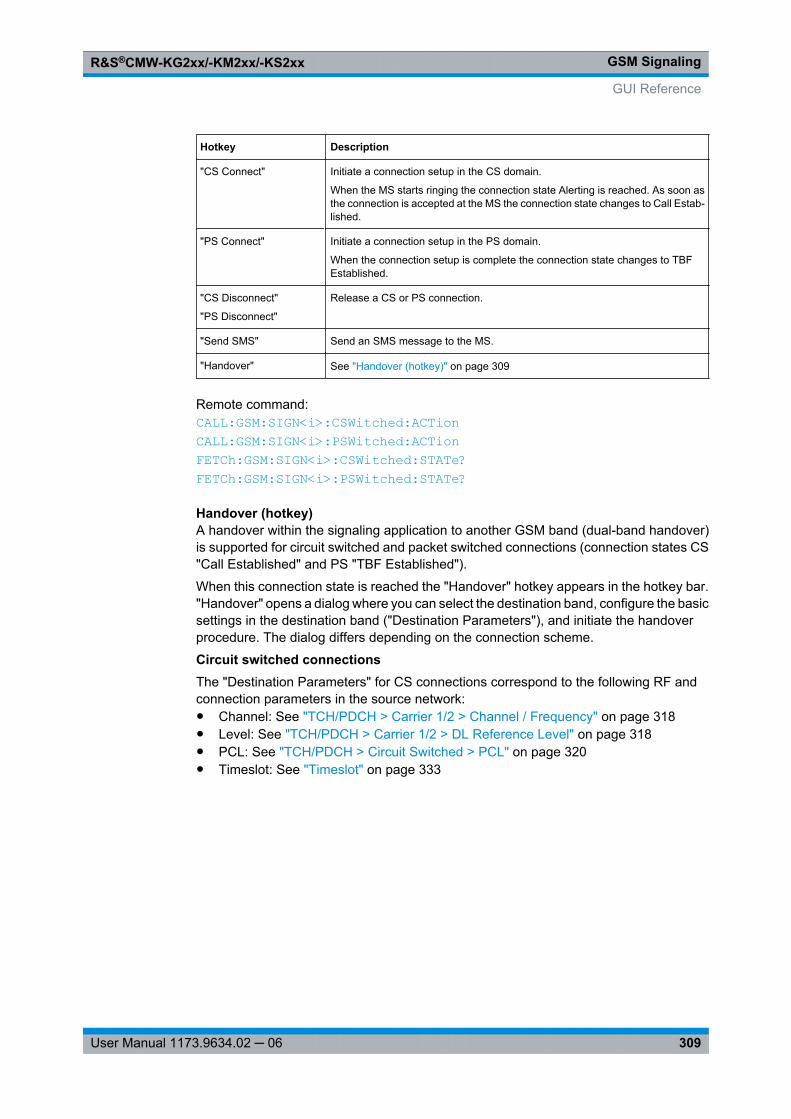
GSM SignalingR&S®CMW-KG2xx/-KM2xx/-KS2xx
309User Manual 1173.9634.02 ─ 06
Hotkey Description
"CS Connect" Initiate a connection setup in the CS domain.
When the MS starts ringing the connection state Alerting is reached. As soon asthe connection is accepted at the MS the connection state changes to Call Estab-lished.
"PS Connect" Initiate a connection setup in the PS domain.
When the connection setup is complete the connection state changes to TBFEstablished.
"CS Disconnect"
"PS Disconnect"
Release a CS or PS connection.
"Send SMS" Send an SMS message to the MS.
"Handover" See "Handover (hotkey)" on page 309
Remote command: CALL: GSM: SIGN<i>: CSWitched: ACTion CALL: GSM: SIGN<i>: PSWitched: ACTion FETCh: GSM: SIGN<i>: CSWitched: STATe? FETCh: GSM: SIGN<i>: PSWitched: STATe?
Handover (hotkey)A handover within the signaling application to another GSM band (dual-band handover)is supported for circuit switched and packet switched connections (connection states CS"Call Established" and PS "TBF Established").
When this connection state is reached the "Handover" hotkey appears in the hotkey bar."Handover" opens a dialog where you can select the destination band, configure the basicsettings in the destination band ("Destination Parameters"), and initiate the handoverprocedure. The dialog differs depending on the connection scheme.
Circuit switched connectionsThe "Destination Parameters" for CS connections correspond to the following RF andconnection parameters in the source network:● Channel: See "TCH/PDCH > Carrier 1/2 > Channel / Frequency" on page 318● Level: See "TCH/PDCH > Carrier 1/2 > DL Reference Level" on page 318● PCL: See "TCH/PDCH > Circuit Switched > PCL" on page 320● Timeslot: See "Timeslot" on page 333
GUI Reference
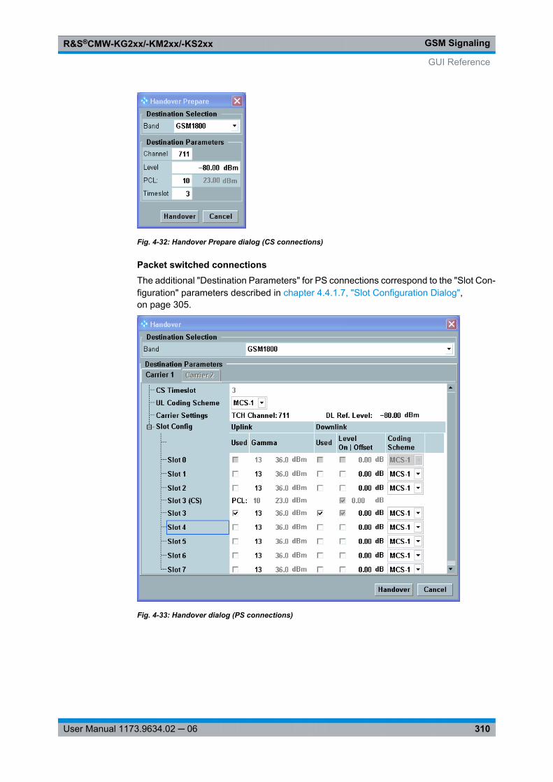
GSM SignalingR&S®CMW-KG2xx/-KM2xx/-KS2xx
310User Manual 1173.9634.02 ─ 06
Fig. 4-32: Handover Prepare dialog (CS connections)
Packet switched connectionsThe additional "Destination Parameters" for PS connections correspond to the "Slot Con-figuration" parameters described in chapter 4.4.1.7, "Slot Configuration Dialog",on page 305.
Fig. 4-33: Handover dialog (PS connections)
GUI Reference
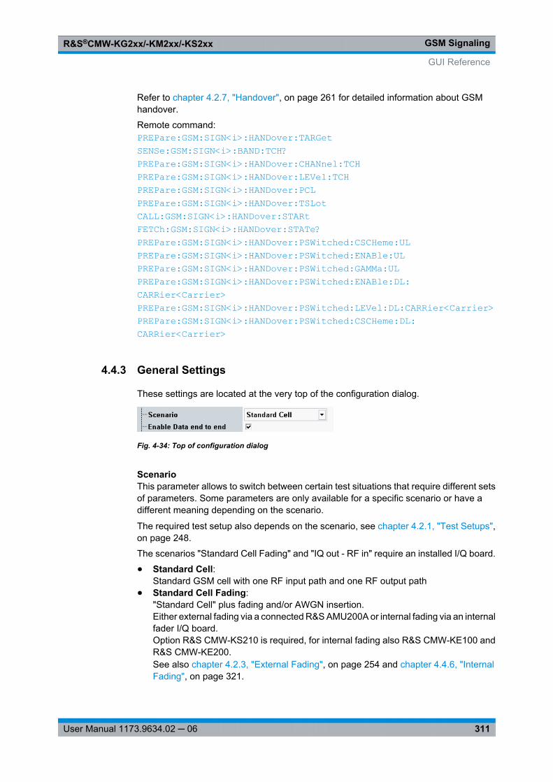
GSM SignalingR&S®CMW-KG2xx/-KM2xx/-KS2xx
311User Manual 1173.9634.02 ─ 06
Refer to chapter 4.2.7, "Handover", on page 261 for detailed information about GSMhandover.
Remote command: PREPare: GSM: SIGN<i>: HANDover: TARGet SENSe: GSM: SIGN<i>: BAND: TCH? PREPare: GSM: SIGN<i>: HANDover: CHANnel: TCH PREPare: GSM: SIGN<i>: HANDover: LEVel: TCH PREPare: GSM: SIGN<i>: HANDover: PCL PREPare: GSM: SIGN<i>: HANDover: TSLot CALL: GSM: SIGN<i>: HANDover: STARt FETCh: GSM: SIGN<i>: HANDover: STATe? PREPare: GSM: SIGN<i>: HANDover: PSWitched: CSCHeme: UL PREPare: GSM: SIGN<i>: HANDover: PSWitched: ENABle: UL PREPare: GSM: SIGN<i>: HANDover: PSWitched: GAMMa: UL PREPare: GSM: SIGN<i>: HANDover: PSWitched: ENABle: DL: CARRier<Carrier> PREPare: GSM: SIGN<i>: HANDover: PSWitched: LEVel: DL: CARRier<Carrier> PREPare: GSM: SIGN<i>: HANDover: PSWitched: CSCHeme: DL: CARRier<Carrier>
4.4.3 General Settings
These settings are located at the very top of the configuration dialog.
Fig. 4-34: Top of configuration dialog
ScenarioThis parameter allows to switch between certain test situations that require different setsof parameters. Some parameters are only available for a specific scenario or have adifferent meaning depending on the scenario.
The required test setup also depends on the scenario, see chapter 4.2.1, "Test Setups",on page 248.
The scenarios "Standard Cell Fading" and "IQ out - RF in" require an installed I/Q board.
● Standard Cell:Standard GSM cell with one RF input path and one RF output path
● Standard Cell Fading:"Standard Cell" plus fading and/or AWGN insertion.Either external fading via a connected R&S AMU200A or internal fading via an internalfader I/Q board.Option R&S CMW-KS210 is required, for internal fading also R&S CMW-KE100 andR&S CMW-KE200.See also chapter 4.2.3, "External Fading", on page 254 and chapter 4.4.6, "InternalFading", on page 321.
GUI Reference
GSM SignalingR&S®CMW-KG2xx/-KM2xx/-KS2xx
312User Manual 1173.9634.02 ─ 06
● IQ out - RF in:RF uplink as for "Standard Cell", baseband downlink via the I/Q board. Allows forexample to insert an R&S SMU200A into the downlink path.
● BCCH and TCH/PDCH:Provides separate downlink signals for the BCCH and the TCH/PDCH.This guarantees that the BCCH is still available after a dual-band handover, even ifthe BCCH band and the TCH band are wide apart and can not be covered by a singledownlink path.When this scenario is active, separate output paths can be configured for the BCCHand the TCH/PDCH (converter, connector and external attenuation). Furthermore,the BCCH level and the TCH/PDCH level can be configured independently.
Remote command: ROUTe: GSM: SIGN<i>: SCENario: SCELl ROUTe: GSM: SIGN<i>: SCENario: IORI ROUTe: GSM: SIGN<i>: SCENario: BATCh ROUTe: GSM: SIGN<i>: SCENario: SCFading[: EXTernal] ROUTe: GSM: SIGN<i>: SCENario: SCFading: INTernal: FFADer ROUTe: GSM: SIGN<i>: SCENario? ROUTe: GSM: SIGN<i>?
Enable Data end to endEnable this parameter if you want to perform IP-based data tests involving the DataApplication Unit (DAU). If this parameter is disabled, no connection is establishedbetween the signaling unit and the DAU.
Only one signaling application with this parameter enabled can be active at a time (cellon / downlink signal present). The parameter is only configurable while the downlink sig-nal is switched off.
The parameter is only displayed if a DAU and option R&S CMW-KA100 are available.
Remote command: CONFigure: GSM: SIGN<i>: ETOE
4.4.4 I/Q Settings
The parameters in this section configure the I/Q output path and/or the I/Q input path.This is relevant for external fading scenarios and for the "I/Q out - RF in" scenario. Onlyfor these scenarios the section is present.
Depending on the scenario the section configures only the I/Q output path or one inputand one output path. Typically an R&S AMU200A or an R&S SMU200A is connected.
When using the "I/Q out - RF in" scenario, it is recommended to specify also the externaldelay of the test setup in the setup dialog. This allows the "GSM Signaling" applicationto compensate a time delay in the output path, which results also in a delayed uplinksignal.
See also: "Digital IQ" in the R&S CMW user manual, chapter "Basic Instrument Functions"
GUI Reference
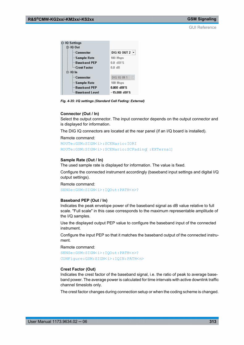
GSM SignalingR&S®CMW-KG2xx/-KM2xx/-KS2xx
313User Manual 1173.9634.02 ─ 06
Fig. 4-35: I/Q settings (Standard Cell Fading: External)
Connector (Out / In)Select the output connector. The input connector depends on the output connector andis displayed for information.
The DIG IQ connectors are located at the rear panel (if an I/Q board is installed).
Remote command: ROUTe: GSM: SIGN<i>: SCENario: IORI ROUTe: GSM: SIGN<i>: SCENario: SCFading[: EXTernal]
Sample Rate (Out / In)The used sample rate is displayed for information. The value is fixed.
Configure the connected instrument accordingly (baseband input settings and digital I/Qoutput settings).
Remote command: SENSe: GSM: SIGN<i>: IQOut: PATH<n>?
Baseband PEP (Out / In)Indicates the peak envelope power of the baseband signal as dB value relative to fullscale. "Full scale" in this case corresponds to the maximum representable amplitude ofthe I/Q samples.
Use the displayed output PEP value to configure the baseband input of the connectedinstrument.
Configure the input PEP so that it matches the baseband output of the connected instru-ment.
Remote command: SENSe: GSM: SIGN<i>: IQOut: PATH<n>? CONFigure: GSM: SIGN<i>: IQIN: PATH<n>
Crest Factor (Out)Indicates the crest factor of the baseband signal, i.e. the ratio of peak to average base-band power. The average power is calculated for time intervals with active downlink trafficchannel timeslots only.
The crest factor changes during connection setup or when the coding scheme is changed.
GUI Reference
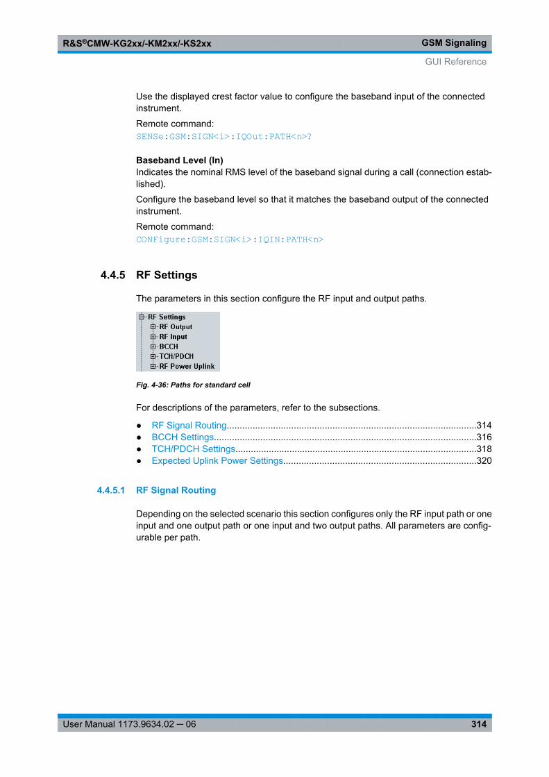
GSM SignalingR&S®CMW-KG2xx/-KM2xx/-KS2xx
314User Manual 1173.9634.02 ─ 06
Use the displayed crest factor value to configure the baseband input of the connectedinstrument.
Remote command: SENSe: GSM: SIGN<i>: IQOut: PATH<n>?
Baseband Level (In)Indicates the nominal RMS level of the baseband signal during a call (connection estab-lished).
Configure the baseband level so that it matches the baseband output of the connectedinstrument.
Remote command: CONFigure: GSM: SIGN<i>: IQIN: PATH<n>
4.4.5 RF Settings
The parameters in this section configure the RF input and output paths.
Fig. 4-36: Paths for standard cell
For descriptions of the parameters, refer to the subsections.
● RF Signal Routing.................................................................................................314● BCCH Settings......................................................................................................316● TCH/PDCH Settings..............................................................................................318● Expected Uplink Power Settings...........................................................................320
4.4.5.1 RF Signal Routing
Depending on the selected scenario this section configures only the RF input path or oneinput and one output path or one input and two output paths. All parameters are config-urable per path.
GUI Reference
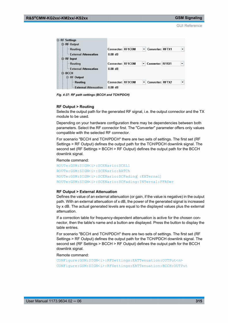
GSM SignalingR&S®CMW-KG2xx/-KM2xx/-KS2xx
315User Manual 1173.9634.02 ─ 06
Fig. 4-37: RF path settings (BCCH and TCH/PDCH)
RF Output > RoutingSelects the output path for the generated RF signal, i.e. the output connector and the TXmodule to be used.
Depending on your hardware configuration there may be dependencies between bothparameters. Select the RF connector first. The "Converter" parameter offers only valuescompatible with the selected RF connector.
For scenario "BCCH and TCH/PDCH" there are two sets of settings. The first set (RFSettings > RF Output) defines the output path for the TCH/PDCH downlink signal. Thesecond set (RF Settings > BCCH > RF Output) defines the output path for the BCCHdownlink signal.
Remote command: ROUTe: GSM: SIGN<i>: SCENario: SCELl ROUTe: GSM: SIGN<i>: SCENario: BATCh ROUTe: GSM: SIGN<i>: SCENario: SCFading[: EXTernal] ROUTe: GSM: SIGN<i>: SCENario: SCFading: INTernal: FFADer
RF Output > External AttenuationDefines the value of an external attenuation (or gain, if the value is negative) in the outputpath. With an external attenuation of x dB, the power of the generated signal is increasedby x dB. The actual generated levels are equal to the displayed values plus the externalattenuation.
If a correction table for frequency-dependent attenuation is active for the chosen con-nector, then the table's name and a button are displayed. Press the button to display thetable entries.
For scenario "BCCH and TCH/PDCH" there are two sets of settings. The first set (RFSettings > RF Output) defines the output path for the TCH/PDCH downlink signal. Thesecond set (RF Settings > BCCH > RF Output) defines the output path for the BCCHdownlink signal.
Remote command: CONFigure: GSM: SIGN<i>: RFSettings: EATTenuation: OUTPut<n> CONFigure: GSM: SIGN<i>: RFSettings: EATTenuation: BCCH: OUTPut
GUI Reference
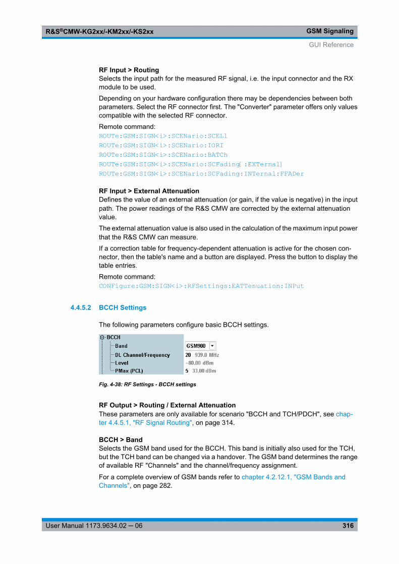
GSM SignalingR&S®CMW-KG2xx/-KM2xx/-KS2xx
316User Manual 1173.9634.02 ─ 06
RF Input > RoutingSelects the input path for the measured RF signal, i.e. the input connector and the RXmodule to be used.
Depending on your hardware configuration there may be dependencies between bothparameters. Select the RF connector first. The "Converter" parameter offers only valuescompatible with the selected RF connector.
Remote command: ROUTe: GSM: SIGN<i>: SCENario: SCELl ROUTe: GSM: SIGN<i>: SCENario: IORI ROUTe: GSM: SIGN<i>: SCENario: BATCh ROUTe: GSM: SIGN<i>: SCENario: SCFading[: EXTernal] ROUTe: GSM: SIGN<i>: SCENario: SCFading: INTernal: FFADer
RF Input > External AttenuationDefines the value of an external attenuation (or gain, if the value is negative) in the inputpath. The power readings of the R&S CMW are corrected by the external attenuationvalue.
The external attenuation value is also used in the calculation of the maximum input powerthat the R&S CMW can measure.
If a correction table for frequency-dependent attenuation is active for the chosen con-nector, then the table's name and a button are displayed. Press the button to display thetable entries.
Remote command: CONFigure: GSM: SIGN<i>: RFSettings: EATTenuation: INPut
4.4.5.2 BCCH Settings
The following parameters configure basic BCCH settings.
Fig. 4-38: RF Settings - BCCH settings
RF Output > Routing / External AttenuationThese parameters are only available for scenario "BCCH and TCH/PDCH", see chap-ter 4.4.5.1, "RF Signal Routing", on page 314.
BCCH > BandSelects the GSM band used for the BCCH. This band is initially also used for the TCH,but the TCH band can be changed via a handover. The GSM band determines the rangeof available RF "Channels" and the channel/frequency assignment.
For a complete overview of GSM bands refer to chapter 4.2.12.1, "GSM Bands andChannels", on page 282.
GUI Reference
GSM SignalingR&S®CMW-KG2xx/-KM2xx/-KS2xx
317User Manual 1173.9634.02 ─ 06
At present, the R&S CMW supports a subset of GSM bands.
Remote command: CONFigure: GSM: SIGN<i>: BAND: BCCH
BCCH > DL Channel/FrequencyGSM channel number for the Broadcast Control Channel (BCCH) that the R&S CMWgenerates in order to set up and maintain the connection to the mobile station under test.The BCCH is transmitted in timeslot no. 0 of the generated GSM downlink signal.
The carrier center frequency corresponding to the channel number is displayed for infor-mation.
The channel settings for the BCCH and the Traffic Channel (TCH) are independent fromeach other. The allowed channel range depends on the selected GSM band.
Remote command: CONFigure: GSM: SIGN<i>: RFSettings: CHANnel: BCCH
BCCH > LevelAbsolute level of the Broadcast Control Channel (BCCH) in dBm.
For scenarios using the same path for all downlink channels (e.g. standard cell), the levelis identical for all channels. In that case the BCCH level is only displayed for informationand is equal to the reference level for the TCH/PDCH channels, see "TCH/PDCH > Car-rier 1/2 > DL Reference Level" on page 318.
For scenarios using separate paths for BCCH and TCH (e.g. "BCCH and TCH/PDCH"scenario), the BCCH level can be configured independently of the reference level.
Remote command: CONFigure: GSM: SIGN<i>: RFSettings: LEVel: BCCH
BCCH > PMax (PCL)Maximum transmitter output level of the MS allowed in the cell. The value correspondsto the output power at which the mobile station performs a location update (access burstlevel).
The level PMax is defined as a Power Control Level (PCL) value in the range between 0and 31. The corresponding absolute level in dBm is displayed for information. The defi-nition of the PCL range depends on the GSM band; see chapter 2.2.5, "Power ControlLevels", on page 15.
Note: After a dual-band handover to another GSM band, PMax is also valid in the desti-nation network. Due to the band-specific PCL scales, the actual maximum MS outputpower changes if one of the bands GSM 1800/GSM 1900 and a lower-frequency bandis involved.Example: PMax = 5, handover from GSM 900 to GSM 1800.
In the original network, PCL 5 corresponds to a maximum output power of 33 dBm, in thedestination network, to 20 dBm. In order to reach the maximum output power of 30 dBmfor GSM 1800, PMax must be set to 0.
Remote command: CONFigure: GSM: SIGN<i>: RFSettings: PMAX: BCCH
GUI Reference
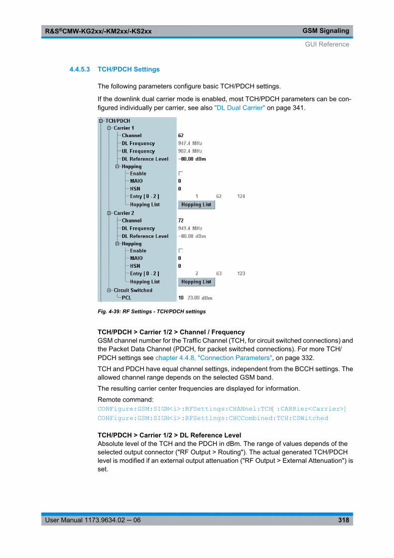
GSM SignalingR&S®CMW-KG2xx/-KM2xx/-KS2xx
318User Manual 1173.9634.02 ─ 06
4.4.5.3 TCH/PDCH Settings
The following parameters configure basic TCH/PDCH settings.
If the downlink dual carrier mode is enabled, most TCH/PDCH parameters can be con-figured individually per carrier, see also "DL Dual Carrier" on page 341.
Fig. 4-39: RF Settings - TCH/PDCH settings
TCH/PDCH > Carrier 1/2 > Channel / FrequencyGSM channel number for the Traffic Channel (TCH, for circuit switched connections) andthe Packet Data Channel (PDCH, for packet switched connections). For more TCH/PDCH settings see chapter 4.4.8, "Connection Parameters", on page 332.
TCH and PDCH have equal channel settings, independent from the BCCH settings. Theallowed channel range depends on the selected GSM band.
The resulting carrier center frequencies are displayed for information.
Remote command: CONFigure: GSM: SIGN<i>: RFSettings: CHANnel: TCH[: CARRier<Carrier>] CONFigure: GSM: SIGN<i>: RFSettings: CHCCombined: TCH: CSWitched
TCH/PDCH > Carrier 1/2 > DL Reference LevelAbsolute level of the TCH and the PDCH in dBm. The range of values depends of theselected output connector ("RF Output > Routing"). The actual generated TCH/PDCHlevel is modified if an external output attenuation ("RF Output > External Attenuation") isset.
GUI Reference
GSM SignalingR&S®CMW-KG2xx/-KM2xx/-KS2xx
319User Manual 1173.9634.02 ─ 06
The R&S CMW uses equal levels for the TCH and the PDCH. Depending on the scenario,the "Reference Level" is also used for the BCCH.
In dual carrier mode both carriers use the same setting.
Remote command: CONFigure: GSM: SIGN<i>: RFSettings: LEVel: TCH[: CARRier<Carrier>]
TCH/PDCH > Carrier 1/2 > Hopping > EnableEnable or disable frequency hopping in the downlink traffic channel.
In GSM networks, frequency hopping is primarily used for error protection in the radiotransmission path. It consists of periodically switching over the transmission channels(except BCCH) to other carrier frequencies. The frequency changes after each radioframe so that the dwell time on each carrier frequency is 4.615 ms ("slow" frequencyhopping).
Frequency hopping is controlled by the network. The BTS transfers a hopping list to themobile station. From this list, the mobile station calculates the radio frequency channelfor each TDMA frame number according to an algorithm described in GSM 45.002.
If hopping is enabled before a connection is established, the hopping information is sentto the MS in the TCH assignment message. At which time during call/connection setupthe traffic channel is assigned depends on the parameter "TCH Assignment"on page 336.
Option R&S CMW-KS210 required.
Remote command: CONFigure: GSM: SIGN<i>: RFSettings: HOPPing: ENABle: TCH[: CARRier<Carrier>]
TCH/PDCH > Carrier 1/2 > Hopping > MAIOThe Mobile Allocation Index Offset (MAIO) determines, together with the HoppingSequence Number (HSN), which entry of the hopping list is used as first value.
The hopping sequence generation is defined in 3GPP TS 45.002, section 6.2.3. For HSN= 0 the number of the list entry applied to frame number 0 equals MAIO modulo N, withN being the length of the hopping list.
Option R&S CMW-KS210 required.
Remote command: CONFigure: GSM: SIGN<i>: RFSettings: HOPPing: MAIO: TCH[: CARRier<Carrier>]
TCH/PDCH > Carrier 1/2 > Hopping > HSNDefines the Hopping Sequence Number (HSN) to be used. The HSN determines in whichorder the hopping list entries are to be used. HSN = 0 results in cyclic hopping (sequen-tially go through the hopping list and at the end go back to the start). All other valuesresult in a non-sequential usage of the hopping list.
Option R&S CMW-KS210 required.
Remote command: CONFigure: GSM: SIGN<i>: RFSettings: HOPPing: HSN: TCH[: CARRier<Carrier>]
GUI Reference
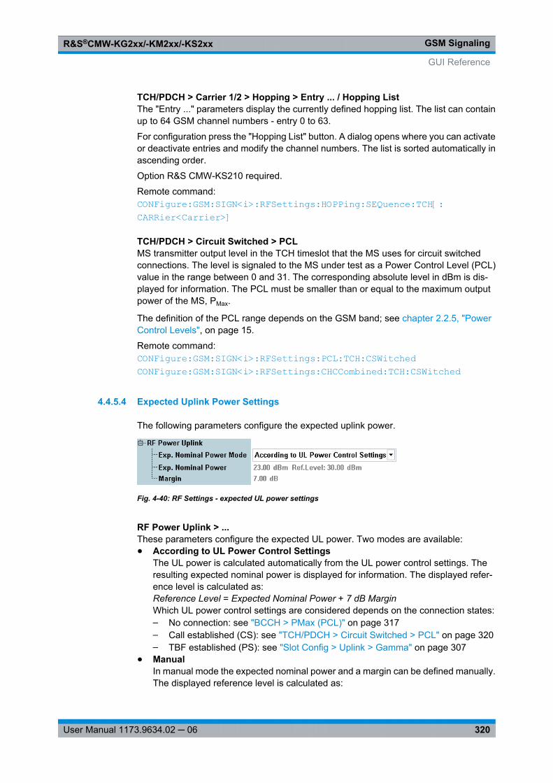
GSM SignalingR&S®CMW-KG2xx/-KM2xx/-KS2xx
320User Manual 1173.9634.02 ─ 06
TCH/PDCH > Carrier 1/2 > Hopping > Entry ... / Hopping ListThe "Entry ..." parameters display the currently defined hopping list. The list can containup to 64 GSM channel numbers - entry 0 to 63.
For configuration press the "Hopping List" button. A dialog opens where you can activateor deactivate entries and modify the channel numbers. The list is sorted automatically inascending order.
Option R&S CMW-KS210 required.
Remote command: CONFigure: GSM: SIGN<i>: RFSettings: HOPPing: SEQuence: TCH[: CARRier<Carrier>]
TCH/PDCH > Circuit Switched > PCLMS transmitter output level in the TCH timeslot that the MS uses for circuit switchedconnections. The level is signaled to the MS under test as a Power Control Level (PCL)value in the range between 0 and 31. The corresponding absolute level in dBm is dis-played for information. The PCL must be smaller than or equal to the maximum outputpower of the MS, PMax.
The definition of the PCL range depends on the GSM band; see chapter 2.2.5, "PowerControl Levels", on page 15.
Remote command: CONFigure: GSM: SIGN<i>: RFSettings: PCL: TCH: CSWitched CONFigure: GSM: SIGN<i>: RFSettings: CHCCombined: TCH: CSWitched
4.4.5.4 Expected Uplink Power Settings
The following parameters configure the expected uplink power.
Fig. 4-40: RF Settings - expected UL power settings
RF Power Uplink > ...These parameters configure the expected UL power. Two modes are available:● According to UL Power Control Settings
The UL power is calculated automatically from the UL power control settings. Theresulting expected nominal power is displayed for information. The displayed refer-ence level is calculated as:Reference Level = Expected Nominal Power + 7 dB MarginWhich UL power control settings are considered depends on the connection states:– No connection: see "BCCH > PMax (PCL)" on page 317– Call established (CS): see "TCH/PDCH > Circuit Switched > PCL" on page 320– TBF established (PS): see "Slot Config > Uplink > Gamma" on page 307
● ManualIn manual mode the expected nominal power and a margin can be defined manually.The displayed reference level is calculated as:
GUI Reference
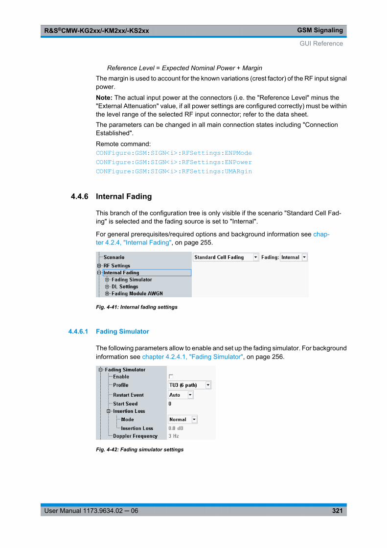
GSM SignalingR&S®CMW-KG2xx/-KM2xx/-KS2xx
321User Manual 1173.9634.02 ─ 06
Reference Level = Expected Nominal Power + MarginThe margin is used to account for the known variations (crest factor) of the RF input signalpower.
Note: The actual input power at the connectors (i.e. the "Reference Level" minus the"External Attenuation" value, if all power settings are configured correctly) must be withinthe level range of the selected RF input connector; refer to the data sheet.The parameters can be changed in all main connection states including "ConnectionEstablished".
Remote command: CONFigure: GSM: SIGN<i>: RFSettings: ENPMode CONFigure: GSM: SIGN<i>: RFSettings: ENPower CONFigure: GSM: SIGN<i>: RFSettings: UMARgin
4.4.6 Internal Fading
This branch of the configuration tree is only visible if the scenario "Standard Cell Fad-ing" is selected and the fading source is set to "Internal".
For general prerequisites/required options and background information see chap-ter 4.2.4, "Internal Fading", on page 255.
Fig. 4-41: Internal fading settings
4.4.6.1 Fading Simulator
The following parameters allow to enable and set up the fading simulator. For backgroundinformation see chapter 4.2.4.1, "Fading Simulator", on page 256.
Fig. 4-42: Fading simulator settings
GUI Reference

GSM SignalingR&S®CMW-KG2xx/-KM2xx/-KS2xx
322User Manual 1173.9634.02 ─ 06
EnableEnables/disables the fading simulator.
Remote command: CONFigure: GSM: SIGN<i>: FADing: FSIMulator: ENABle
ProfileSelects one of the multipath propagation condition profiles defined in Annex C.3 of 3GPPTS 45.005.
The following types of propagation models are supported: TU (urban area), HT (hillyterrain), RA (rural area), EQ (equalization test) and TI (very small cell).
All models involve a movement of the MS. The speed of movement in km/h is indicatedas part of the profile name. The number of propagation paths is also indicated.
Example: "TU3 (6 path)" means urban area, MS moving with 3 km/h, 6 propagation paths.
Remote command: CONFigure: GSM: SIGN<i>: FADing: FSIMulator: STANdard
Restart EventIn "Auto" mode, fading automatically starts with the downlink signal. In "Manual" mode,it is started and restarted manually.
Remote command: CONFigure: GSM: SIGN<i>: FADing: FSIMulator: RESTart: MODE CONFigure: GSM: SIGN<i>: FADing: FSIMulator: RESTart
Start SeedSets the start seed for the pseudo-random fading algorithm. This enables reproduciblefading conditions.
Remote command: CONFigure: GSM: SIGN<i>: FADing: FSIMulator: GLOBal: SEED
Insertion LossIn "Normal" mode, the insertion loss (i.e. the required attenuation at fader input) is cal-culated based on the currently selected Profile. In "Manual" mode it can be adjusted bythe user.
A lower insertion loss allows for a higher downlink power but may result in clipping.
Remote command: CONFigure: GSM: SIGN<i>: FADing: FSIMulator: ILOSs: MODE CONFigure: GSM: SIGN<i>: FADing: FSIMulator: ILOSs: LOSS
Doppler FrequencyDisplays the maximum Doppler frequency resulting from the selected fading profile.
4.4.6.2 DL Settings
This branch displays noise power values, calculated from the downlink power and theAWGN settings.
GUI Reference
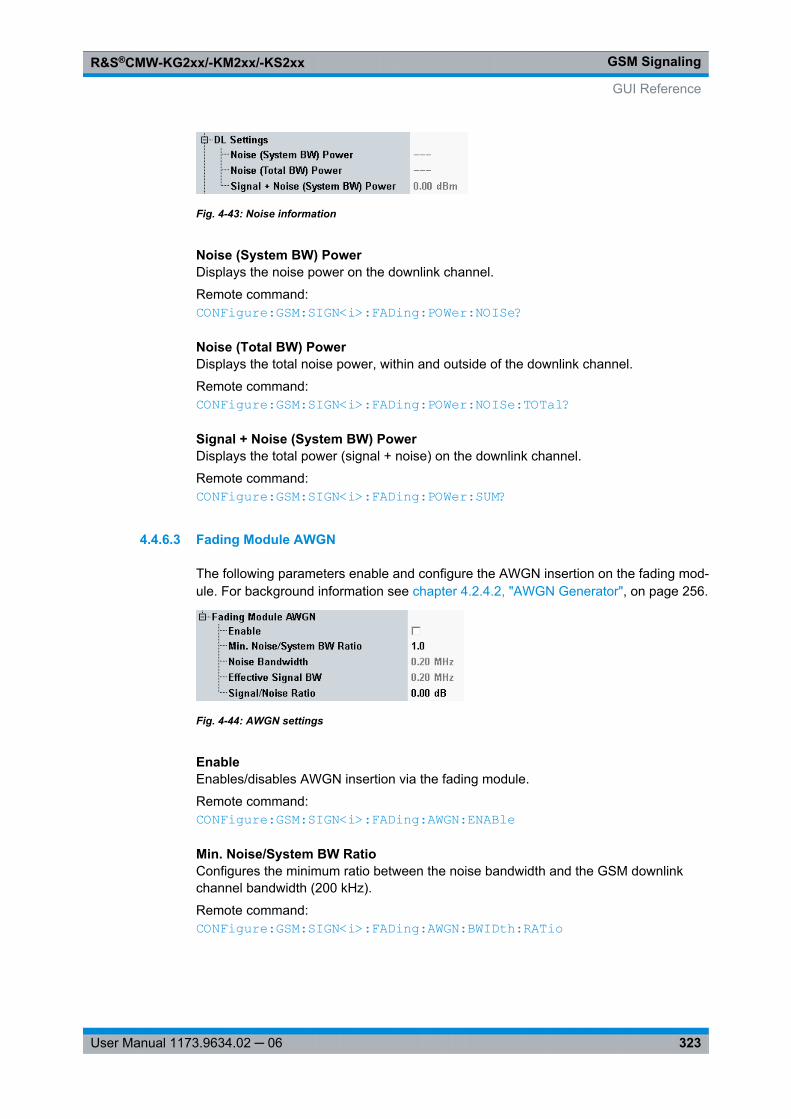
GSM SignalingR&S®CMW-KG2xx/-KM2xx/-KS2xx
323User Manual 1173.9634.02 ─ 06
Fig. 4-43: Noise information
Noise (System BW) PowerDisplays the noise power on the downlink channel.
Remote command: CONFigure: GSM: SIGN<i>: FADing: POWer: NOISe?
Noise (Total BW) PowerDisplays the total noise power, within and outside of the downlink channel.
Remote command: CONFigure: GSM: SIGN<i>: FADing: POWer: NOISe: TOTal?
Signal + Noise (System BW) PowerDisplays the total power (signal + noise) on the downlink channel.
Remote command: CONFigure: GSM: SIGN<i>: FADing: POWer: SUM?
4.4.6.3 Fading Module AWGN
The following parameters enable and configure the AWGN insertion on the fading mod-ule. For background information see chapter 4.2.4.2, "AWGN Generator", on page 256.
Fig. 4-44: AWGN settings
EnableEnables/disables AWGN insertion via the fading module.
Remote command: CONFigure: GSM: SIGN<i>: FADing: AWGN: ENABle
Min. Noise/System BW RatioConfigures the minimum ratio between the noise bandwidth and the GSM downlinkchannel bandwidth (200 kHz).
Remote command: CONFigure: GSM: SIGN<i>: FADing: AWGN: BWIDth: RATio
GUI Reference
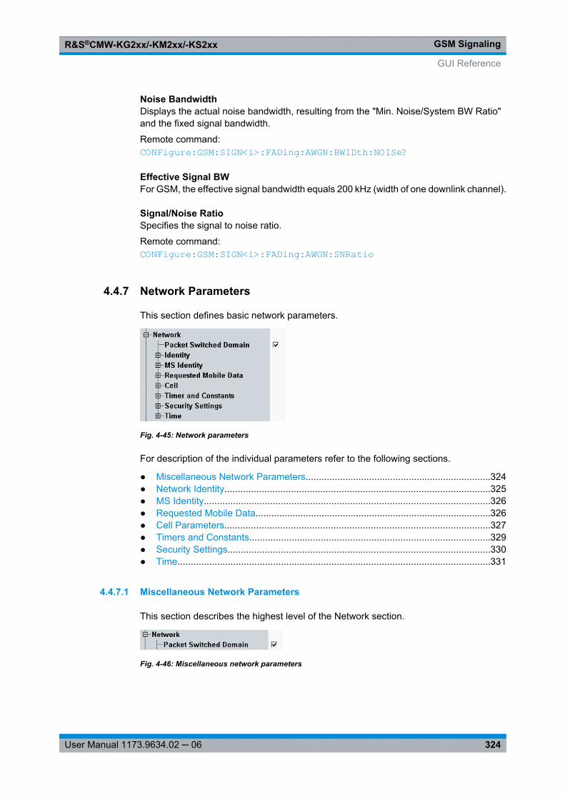
GSM SignalingR&S®CMW-KG2xx/-KM2xx/-KS2xx
324User Manual 1173.9634.02 ─ 06
Noise BandwidthDisplays the actual noise bandwidth, resulting from the "Min. Noise/System BW Ratio"and the fixed signal bandwidth.
Remote command: CONFigure: GSM: SIGN<i>: FADing: AWGN: BWIDth: NOISe?
Effective Signal BWFor GSM, the effective signal bandwidth equals 200 kHz (width of one downlink channel).
Signal/Noise RatioSpecifies the signal to noise ratio.
Remote command: CONFigure: GSM: SIGN<i>: FADing: AWGN: SNRatio
4.4.7 Network Parameters
This section defines basic network parameters.
Fig. 4-45: Network parameters
For description of the individual parameters refer to the following sections.
● Miscellaneous Network Parameters......................................................................324● Network Identity....................................................................................................325● MS Identity............................................................................................................326● Requested Mobile Data.........................................................................................326● Cell Parameters....................................................................................................327● Timers and Constants...........................................................................................329● Security Settings...................................................................................................330● Time......................................................................................................................331
4.4.7.1 Miscellaneous Network Parameters
This section describes the highest level of the Network section.
Fig. 4-46: Miscellaneous network parameters
GUI Reference
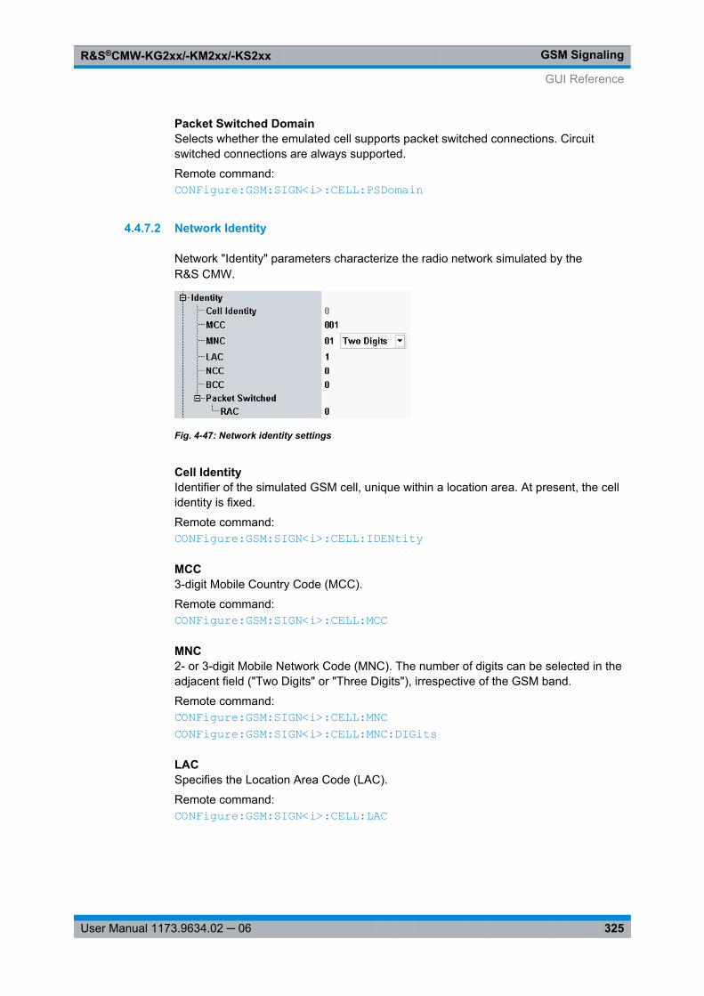
GSM SignalingR&S®CMW-KG2xx/-KM2xx/-KS2xx
325User Manual 1173.9634.02 ─ 06
Packet Switched DomainSelects whether the emulated cell supports packet switched connections. Circuitswitched connections are always supported.
Remote command: CONFigure: GSM: SIGN<i>: CELL: PSDomain
4.4.7.2 Network Identity
Network "Identity" parameters characterize the radio network simulated by theR&S CMW.
Fig. 4-47: Network identity settings
Cell IdentityIdentifier of the simulated GSM cell, unique within a location area. At present, the cellidentity is fixed.
Remote command: CONFigure: GSM: SIGN<i>: CELL: IDENtity
MCC3-digit Mobile Country Code (MCC).
Remote command: CONFigure: GSM: SIGN<i>: CELL: MCC
MNC2- or 3-digit Mobile Network Code (MNC). The number of digits can be selected in theadjacent field ("Two Digits" or "Three Digits"), irrespective of the GSM band.
Remote command: CONFigure: GSM: SIGN<i>: CELL: MNC CONFigure: GSM: SIGN<i>: CELL: MNC: DIGits
LACSpecifies the Location Area Code (LAC).
Remote command: CONFigure: GSM: SIGN<i>: CELL: LAC
GUI Reference
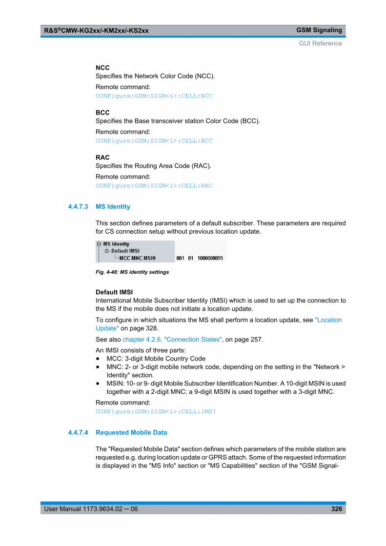
GSM SignalingR&S®CMW-KG2xx/-KM2xx/-KS2xx
326User Manual 1173.9634.02 ─ 06
NCCSpecifies the Network Color Code (NCC).
Remote command: CONFigure: GSM: SIGN<i>: CELL: NCC
BCCSpecifies the Base transceiver station Color Code (BCC).
Remote command: CONFigure: GSM: SIGN<i>: CELL: BCC
RACSpecifies the Routing Area Code (RAC).
Remote command: CONFigure: GSM: SIGN<i>: CELL: RAC
4.4.7.3 MS Identity
This section defines parameters of a default subscriber. These parameters are requiredfor CS connection setup without previous location update.
Fig. 4-48: MS identity settings
Default IMSIInternational Mobile Subscriber Identity (IMSI) which is used to set up the connection tothe MS if the mobile does not initiate a location update.
To configure in which situations the MS shall perform a location update, see "LocationUpdate" on page 328.
See also chapter 4.2.6, "Connection States", on page 257.
An IMSI consists of three parts:● MCC: 3-digit Mobile Country Code● MNC: 2- or 3-digit mobile network code, depending on the setting in the "Network >
Identity" section.● MSIN: 10- or 9- digit Mobile Subscriber Identification Number. A 10-digit MSIN is used
together with a 2-digit MNC; a 9-digit MSIN is used together with a 3-digit MNC.
Remote command: CONFigure: GSM: SIGN<i>: CELL: IMSI
4.4.7.4 Requested Mobile Data
The "Requested Mobile Data" section defines which parameters of the mobile station arerequested e.g. during location update or GPRS attach. Some of the requested informationis displayed in the "MS Info" section or "MS Capabilities" section of the "GSM Signal-
GUI Reference
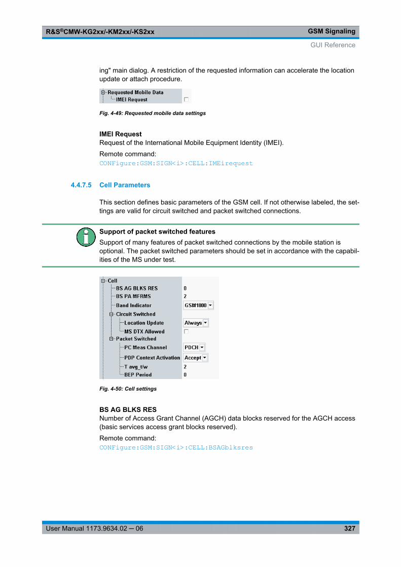
GSM SignalingR&S®CMW-KG2xx/-KM2xx/-KS2xx
327User Manual 1173.9634.02 ─ 06
ing" main dialog. A restriction of the requested information can accelerate the locationupdate or attach procedure.
Fig. 4-49: Requested mobile data settings
IMEI RequestRequest of the International Mobile Equipment Identity (IMEI).
Remote command: CONFigure: GSM: SIGN<i>: CELL: IMEirequest
4.4.7.5 Cell Parameters
This section defines basic parameters of the GSM cell. If not otherwise labeled, the set-tings are valid for circuit switched and packet switched connections.
Support of packet switched featuresSupport of many features of packet switched connections by the mobile station isoptional. The packet switched parameters should be set in accordance with the capabil-ities of the MS under test.
Fig. 4-50: Cell settings
BS AG BLKS RESNumber of Access Grant Channel (AGCH) data blocks reserved for the AGCH access(basic services access grant blocks reserved).
Remote command: CONFigure: GSM: SIGN<i>: CELL: BSAGblksres
GUI Reference
GSM SignalingR&S®CMW-KG2xx/-KM2xx/-KS2xx
328User Manual 1173.9634.02 ─ 06
BS PA MFRMSInterval between two paging requests of the R&S CMW in multiframes (basic servicepaging blocks available per multiframes).
Remote command: CONFigure: GSM: SIGN<i>: CELL: BSPamfrms
Band IndicatorIndication of the band GSM 1800 or GSM 1900 that the current BCCH and TCH/PDCHchannels belong to. The parameter is relevant for mobiles which can operate in theGSM1800 and in the GSM 1900 bands. The information on the band is important becausethe two bands partially use the same channel numbers for different frequencies.
Remote command: CONFigure: GSM: SIGN<i>: CELL: BINDicator
Circuit SwitchedThe following parameters configure the cell for CS connections.
Location Update ← Circuit SwitchedDefines in which instances the MS performs a location update and provides registrationinformation (e.g. the IMSI) so that the R&S CMW can enter the "Synchronized" connec-tion state.
See also chapter 4.2.6, "Connection States", on page 257.
"Always" Location update each time the mobile station is switched on.
"Auto" Location update only if the mobile detects that it is no longer registered,e.g. because the SIM card or the network IDs of the R&S CMW (e.g.the LAC) are changed. In "Auto" mode, it is possible to initiate a con-nection from the "CS On" state using the default IMSI. This can be fasterthan the ordinary connection scheme, provided that it is possible todetermine the time when the mobile is synchronized to the cell signal.
Remote command: CONFigure: GSM: SIGN<i>: CELL: LUPDate
MS DTX Allowed ← Circuit SwitchedSpecifies whether or not the mobile station may use the operating mode DTX (Discon-tinuous Transmission).
In discontinuous transmission mode the voice activity detection of the mobile stationanalyzes the language elements and the time intervals in-between in order to decidewhether a transmission is required. As a result of this analysis, only useful information istransferred; if nothing is spoken, the mobile station will not transmit anything. DTX modereduces radio interference and power consumption of the mobile stations.
Note: The DTX mode is disabled by default to ensure that TX measurements can beperformed at maximum speed.
Remote command: CONFigure: GSM: SIGN<i>: CELL: DTX
Packet SwitchedThe following parameters configure the cell for PS connections.
GUI Reference
GSM SignalingR&S®CMW-KG2xx/-KM2xx/-KS2xx
329User Manual 1173.9634.02 ─ 06
PC Meas Channel ← Packet SwitchedChannel type (BCCH or PDCH) that the mobile uses to determine the received signalstrength and quality. The parameter corresponds to the GPRS power control parameterPC_MEAS_CHAN in the system information 13 Rest Octets (3GPP TS 44.018) andpacket system information 13 (3GPP TS 44.060).
Option R&S CMW-KS210 is required.
Remote command: CONFigure: GSM: SIGN<i>: CELL: PSWitched: PCMChannel
PDP Context Activation ← Packet SwitchedDefines how the R&S CMW reacts to a PDP context activation initiated by the MS. PacketData Protocol (PDP) is a network protocol used by an external packet data network inter-facing to GPRS.
The R&S CMW can accept or reject an ACTIVATE PDP CONTEXT REQUEST from theMS (see 3GPP TS 24.008). The purpose of the setting is to prevent the MS from attempt-ing repeated PDP context requests. Which setting is suitable depends on the mobile type.
Remote command: CONFigure: GSM: SIGN<i>: CELL: PSWitched: PDPContext
T avg_t/w ← Packet SwitchedSpecifies the signal level filter period for power control in packet transfer mode (TAVG_T)and packet idle mode (TAVG_W) as defined in 3GPP TS 45.008. With an entered value k,the filter period is 2k/2/6 multiframes. This parameter defines the update rate of themobile's PS measurement reports (the larger k, the slower the measurement reports areupdated).
Option R&S CMW-KS210 is required.
Remote command: CONFigure: GSM: SIGN<i>: CELL: PSWitched: TAVGtw
BEP Period ← Packet SwitchedConfigures the BEP_PERIOD specified in 3GPP TS 45.008, section 10.2.3.2.1.
The BEP period is a filter constant for EGPRS channel quality measurements (measure-ment reports) that the MS uses for the calculation of the Mean BEP and the CV BEPvalues. BEP_PERIOD is broadcast in the system information.
Option R&S CMW-KS210 is required.
Remote command: CONFigure: GSM: SIGN<i>: CELL: PSWitched: BPERiod
4.4.7.6 Timers and Constants
The following parameters control the timing of the connection.
GUI Reference
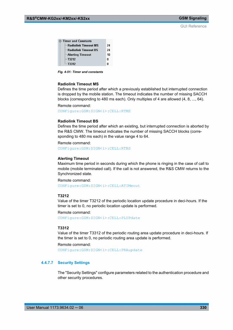
GSM SignalingR&S®CMW-KG2xx/-KM2xx/-KS2xx
330User Manual 1173.9634.02 ─ 06
Fig. 4-51: Timer and constants
Radiolink Timeout MSDefines the time period after which a previously established but interrupted connectionis dropped by the mobile station. The timeout indicates the number of missing SACCHblocks (corresponding to 480 ms each). Only multiples of 4 are allowed (4, 8, ..., 64).
Remote command: CONFigure: GSM: SIGN<i>: CELL: RTMS
Radiolink Timeout BSDefines the time period after which an existing, but interrupted connection is aborted bythe R&S CMW. The timeout indicates the number of missing SACCH blocks (corre-sponding to 480 ms each) in the value range 4 to 64.
Remote command: CONFigure: GSM: SIGN<i>: CELL: RTBS
Alerting TimeoutMaximum time period in seconds during which the phone is ringing in the case of call tomobile (mobile terminated call). If the call is not answered, the R&S CMW returns to theSynchronized state.
Remote command: CONFigure: GSM: SIGN<i>: CELL: ATIMeout
T3212Value of the timer T3212 of the periodic location update procedure in deci-hours. If thetimer is set to 0, no periodic location update is performed.
Remote command: CONFigure: GSM: SIGN<i>: CELL: PLUPdate
T3312Value of the timer T3312 of the periodic routing area update procedure in deci-hours. Ifthe timer is set to 0, no periodic routing area update is performed.
Remote command: CONFigure: GSM: SIGN<i>: CELL: PRAupdate
4.4.7.7 Security Settings
The "Security Settings" configure parameters related to the authentication procedure andother security procedures.
GUI Reference
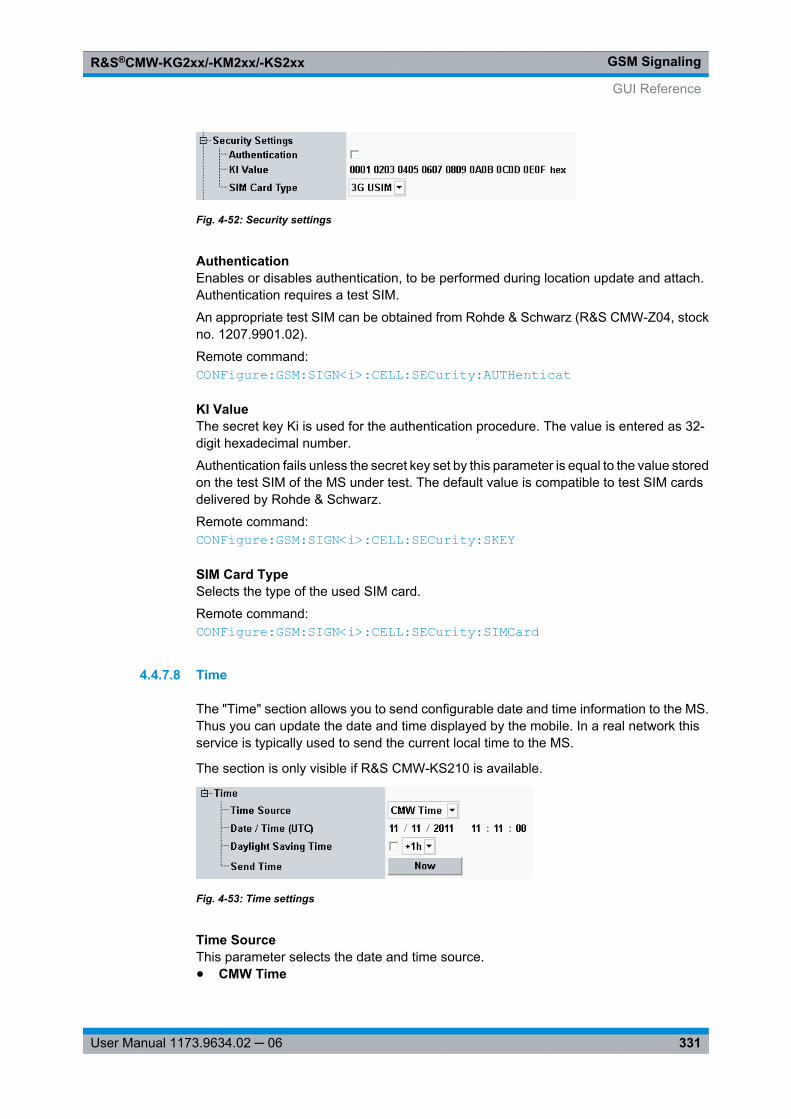
GSM SignalingR&S®CMW-KG2xx/-KM2xx/-KS2xx
331User Manual 1173.9634.02 ─ 06
Fig. 4-52: Security settings
AuthenticationEnables or disables authentication, to be performed during location update and attach.Authentication requires a test SIM.
An appropriate test SIM can be obtained from Rohde & Schwarz (R&S CMW-Z04, stockno. 1207.9901.02).
Remote command: CONFigure: GSM: SIGN<i>: CELL: SECurity: AUTHenticat
KI ValueThe secret key Ki is used for the authentication procedure. The value is entered as 32-digit hexadecimal number.
Authentication fails unless the secret key set by this parameter is equal to the value storedon the test SIM of the MS under test. The default value is compatible to test SIM cardsdelivered by Rohde & Schwarz.
Remote command: CONFigure: GSM: SIGN<i>: CELL: SECurity: SKEY
SIM Card TypeSelects the type of the used SIM card.
Remote command: CONFigure: GSM: SIGN<i>: CELL: SECurity: SIMCard
4.4.7.8 Time
The "Time" section allows you to send configurable date and time information to the MS.Thus you can update the date and time displayed by the mobile. In a real network thisservice is typically used to send the current local time to the MS.
The section is only visible if R&S CMW-KS210 is available.
Fig. 4-53: Time settings
Time SourceThis parameter selects the date and time source.● CMW Time
GUI Reference
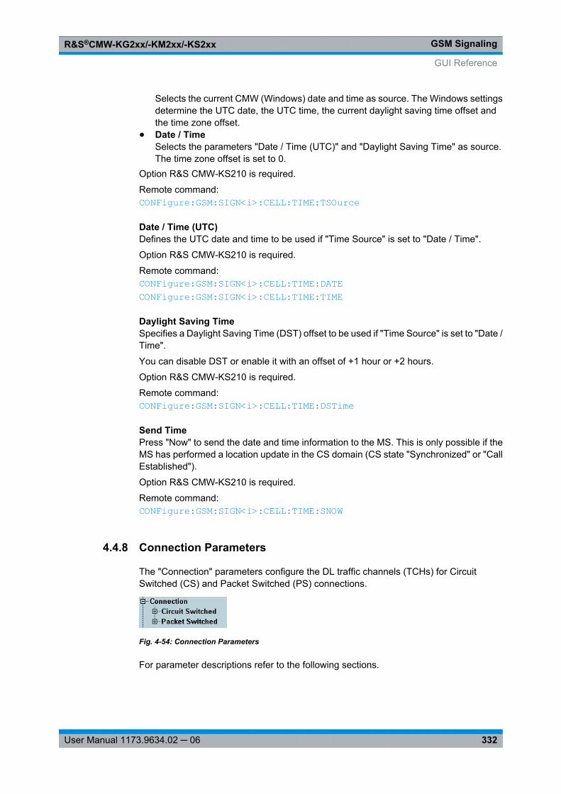
GSM SignalingR&S®CMW-KG2xx/-KM2xx/-KS2xx
332User Manual 1173.9634.02 ─ 06
Selects the current CMW (Windows) date and time as source. The Windows settingsdetermine the UTC date, the UTC time, the current daylight saving time offset andthe time zone offset.
● Date / TimeSelects the parameters "Date / Time (UTC)" and "Daylight Saving Time" as source.The time zone offset is set to 0.
Option R&S CMW-KS210 is required.
Remote command: CONFigure: GSM: SIGN<i>: CELL: TIME: TSOurce
Date / Time (UTC)Defines the UTC date and time to be used if "Time Source" is set to "Date / Time".
Option R&S CMW-KS210 is required.
Remote command: CONFigure: GSM: SIGN<i>: CELL: TIME: DATE CONFigure: GSM: SIGN<i>: CELL: TIME: TIME
Daylight Saving TimeSpecifies a Daylight Saving Time (DST) offset to be used if "Time Source" is set to "Date /Time".
You can disable DST or enable it with an offset of +1 hour or +2 hours.
Option R&S CMW-KS210 is required.
Remote command: CONFigure: GSM: SIGN<i>: CELL: TIME: DSTime
Send TimePress "Now" to send the date and time information to the MS. This is only possible if theMS has performed a location update in the CS domain (CS state "Synchronized" or "CallEstablished").
Option R&S CMW-KS210 is required.
Remote command: CONFigure: GSM: SIGN<i>: CELL: TIME: SNOW
4.4.8 Connection Parameters
The "Connection" parameters configure the DL traffic channels (TCHs) for CircuitSwitched (CS) and Packet Switched (PS) connections.
Fig. 4-54: Connection Parameters
For parameter descriptions refer to the following sections.
GUI Reference
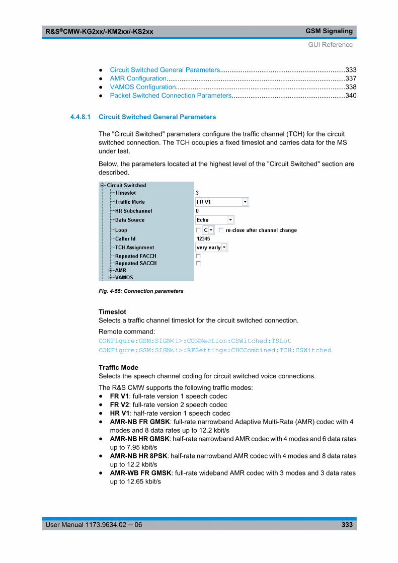
GSM SignalingR&S®CMW-KG2xx/-KM2xx/-KS2xx
333User Manual 1173.9634.02 ─ 06
● Circuit Switched General Parameters...................................................................333● AMR Configuration................................................................................................337● VAMOS Configuration...........................................................................................338● Packet Switched Connection Parameters.............................................................340
4.4.8.1 Circuit Switched General Parameters
The "Circuit Switched" parameters configure the traffic channel (TCH) for the circuitswitched connection. The TCH occupies a fixed timeslot and carries data for the MSunder test.
Below, the parameters located at the highest level of the "Circuit Switched" section aredescribed.
Fig. 4-55: Connection parameters
TimeslotSelects a traffic channel timeslot for the circuit switched connection.
Remote command: CONFigure: GSM: SIGN<i>: CONNection: CSWitched: TSLot CONFigure: GSM: SIGN<i>: RFSettings: CHCCombined: TCH: CSWitched
Traffic ModeSelects the speech channel coding for circuit switched voice connections.
The R&S CMW supports the following traffic modes:● FR V1: full-rate version 1 speech codec● FR V2: full-rate version 2 speech codec● HR V1: half-rate version 1 speech codec● AMR-NB FR GMSK: full-rate narrowband Adaptive Multi-Rate (AMR) codec with 4
modes and 8 data rates up to 12.2 kbit/s● AMR-NB HR GMSK: half-rate narrowband AMR codec with 4 modes and 6 data rates
up to 7.95 kbit/s● AMR-NB HR 8PSK: half-rate narrowband AMR codec with 4 modes and 8 data rates
up to 12.2 kbit/s● AMR-WB FR GMSK: full-rate wideband AMR codec with 3 modes and 3 data rates
up to 12.65 kbit/s
GUI Reference
GSM SignalingR&S®CMW-KG2xx/-KM2xx/-KS2xx
334User Manual 1173.9634.02 ─ 06
● AMR-WB FR 8PSK: full-rate wideband AMR codec with 4 modes and 5 data ratesup to 23.85 kbit/s
● AMR-WB HR 8PSK: half-rate wideband AMR codec with 3 modes and 3 data ratesup to 12.65 kbit/s
Option R&S CMW-KS210 required for all modes except "FR V1".
For configuration of the AMR modes see chapter 4.4.8.2, "AMR Configuration",on page 337.
Remote command: CONFigure: GSM: SIGN<i>: CONNection: CSWitched: TMODe
HR SubchannelSelects the subchannel to be used for half-rate coding. Only half of the TDMA frames areused for a connection with half-rate coding, so that two subchannels numbered 0 and 1are available.
Option R&S CMW-KS210 is required.
Remote command: CONFigure: GSM: SIGN<i>: CONNection: CSWitched: HRSubchannel
Data SourceSelects the data which the R&S CMW transmits on its DL traffic channel.
The "Echo" setting is appropriate for audio tests; the Pseudo Random Bit Sequences(PRBS) are appropriate for receiver quality measurements. The PRBS data are fullychannel coded (including bit swapping and interleaving).
Note: When a BER CS measurement is turned on, this parameter is configured auto-matically and grayed out. See also chapter 4.2.9, "BER CS Measurement",on page 263.● Echo:
Loop-back with delay: All UL speech data received from the mobile is sent back aftera fixed delay. If the R&S CMW does not receive speech data in this operating mode,it automatically transmits a specific bit pattern in order to produce "silence" in thereceiver of the mobile station.This mode is suitable for a simple test of the connection: A word spoken into themicrophone of the mobile should be returned after a short while.The mode is incompatible with an enabled test loop.
● PRBS 2E9-1, PRBS 2E11-1:PRBS transmission according to CCITT (ITU-T) O.153
● PRBS 2E15-1:PRBS transmission according to CCITT (ITU-T) O.151
● PRBS 2E16-1:Transmission of a pseudo random bit sequence defined by the polynomial: x16 + x5
+ x3 + x2 + 1
Remote command: CONFigure: GSM: SIGN<i>: CONNection: CSWitched: DSOurce
LoopActivates/deactivates a test loop and selects the loop type. All test loops are defined in3GPP TS 44.014. For an overview see also chapter 4.2.9.8, "Test Loops", on page 270.
GUI Reference
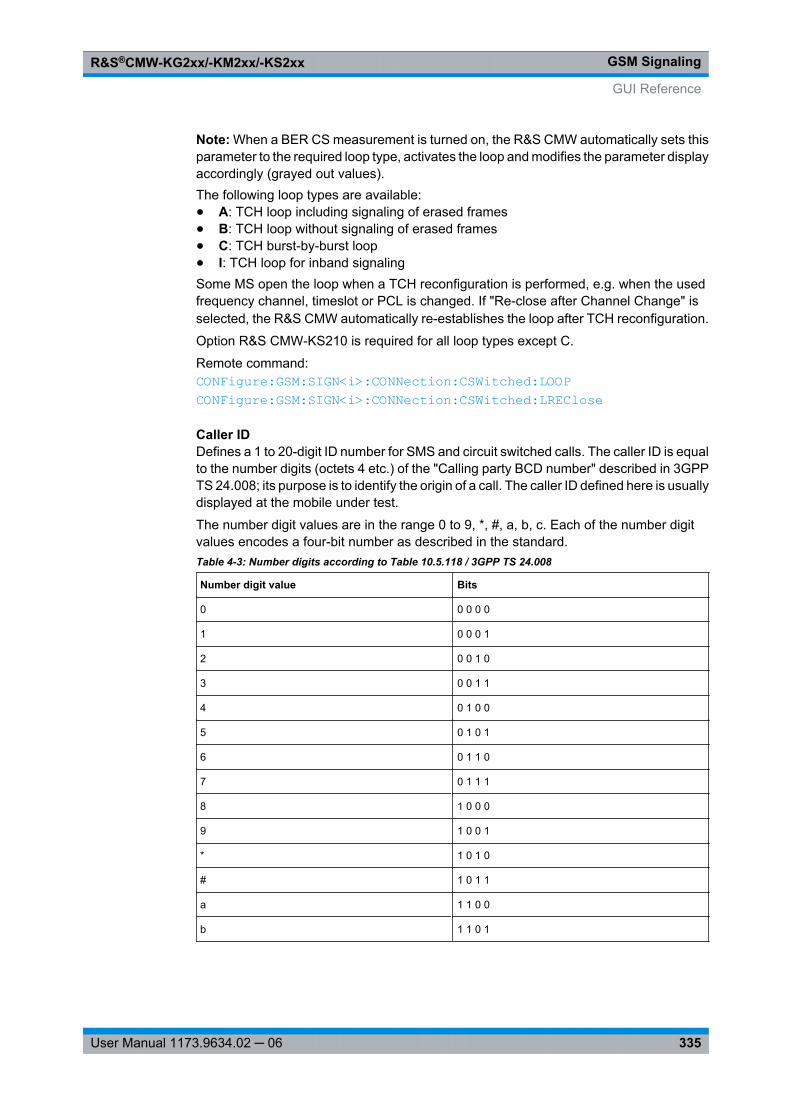
GSM SignalingR&S®CMW-KG2xx/-KM2xx/-KS2xx
335User Manual 1173.9634.02 ─ 06
Note: When a BER CS measurement is turned on, the R&S CMW automatically sets thisparameter to the required loop type, activates the loop and modifies the parameter displayaccordingly (grayed out values).The following loop types are available:● A: TCH loop including signaling of erased frames● B: TCH loop without signaling of erased frames● C: TCH burst-by-burst loop● I: TCH loop for inband signalingSome MS open the loop when a TCH reconfiguration is performed, e.g. when the usedfrequency channel, timeslot or PCL is changed. If "Re-close after Channel Change" isselected, the R&S CMW automatically re-establishes the loop after TCH reconfiguration.
Option R&S CMW-KS210 is required for all loop types except C.
Remote command: CONFigure: GSM: SIGN<i>: CONNection: CSWitched: LOOP CONFigure: GSM: SIGN<i>: CONNection: CSWitched: LREClose
Caller IDDefines a 1 to 20-digit ID number for SMS and circuit switched calls. The caller ID is equalto the number digits (octets 4 etc.) of the "Calling party BCD number" described in 3GPPTS 24.008; its purpose is to identify the origin of a call. The caller ID defined here is usuallydisplayed at the mobile under test.
The number digit values are in the range 0 to 9, *, #, a, b, c. Each of the number digitvalues encodes a four-bit number as described in the standard.Table 4-3: Number digits according to Table 10.5.118 / 3GPP TS 24.008
Number digit value Bits
0 0 0 0 0
1 0 0 0 1
2 0 0 1 0
3 0 0 1 1
4 0 1 0 0
5 0 1 0 1
6 0 1 1 0
7 0 1 1 1
8 1 0 0 0
9 1 0 0 1
* 1 0 1 0
# 1 0 1 1
a 1 1 0 0
b 1 1 0 1
GUI Reference
GSM SignalingR&S®CMW-KG2xx/-KM2xx/-KS2xx
336User Manual 1173.9634.02 ─ 06
Number digit value Bits
c 1 1 1 0
used as an endmark in the case of an odd number ofnumber digits
1 1 1 1
Remote command: CONFigure: GSM: SIGN<i>: CONNection: CSWitched: CID
TCH AssignmentSpecifies at which time during call/connection setup the traffic channel is assigned:● very early: The TCH is assigned very early. Signaling is done via the Fast Associated
Control Channel (FACCH).● early: The TCH is assigned early, which means that alerting takes place on the TCH.
For call setup to the traffic channel signaling is done via the Standalone DedicatedControl Channel (SDCCH).
● late: The traffic channel is assigned late, which means after alerting. For call setupto the traffic channel and alerting signaling is done via the SDCCH. This is also knownas Off-Air Call Setup (OACSU).
Remote command: CONFigure: GSM: SIGN<i>: CONNection: CSWitched: TCHassign
Repeated FACCHSpecifies how often each DL FACCH frame (L2 frame) is transmitted.● Off: Each L2 frame is transmitted once. The usual L2 protocol is applied.● On: Each L2 frame is transmitted twice. The purpose of repeated FACCH is to
improve the robustness of FACCH signaling; its main application on the R&S CMWis the repeated FACCH frame error rate test described in chapter 4.2.9.5, "Mode "FERFACCH"", on page 266.
Option R&S CMW-KS210 is required.
Remote command: CONFigure: GSM: SIGN<i>: CONNection: CSWitched: RFACch
Repeated SACCHSpecifies how often each DL SACCH frame is transmitted.● Off: Each SACCH frame is transmitted once.● On: Each L2 frame is transmitted twice. The purpose of repeated SACCH is to
improve the robustness of SACCH signaling; its main application on the R&S CMWis the repeated SACCH frame error rate test described in chapter 4.2.9.6, "Mode"FER SACCH"", on page 267.
Option R&S CMW-KS210 is required.
Remote command: CONFigure: GSM: SIGN<i>: CONNection: CSWitched: RSACch
GUI Reference
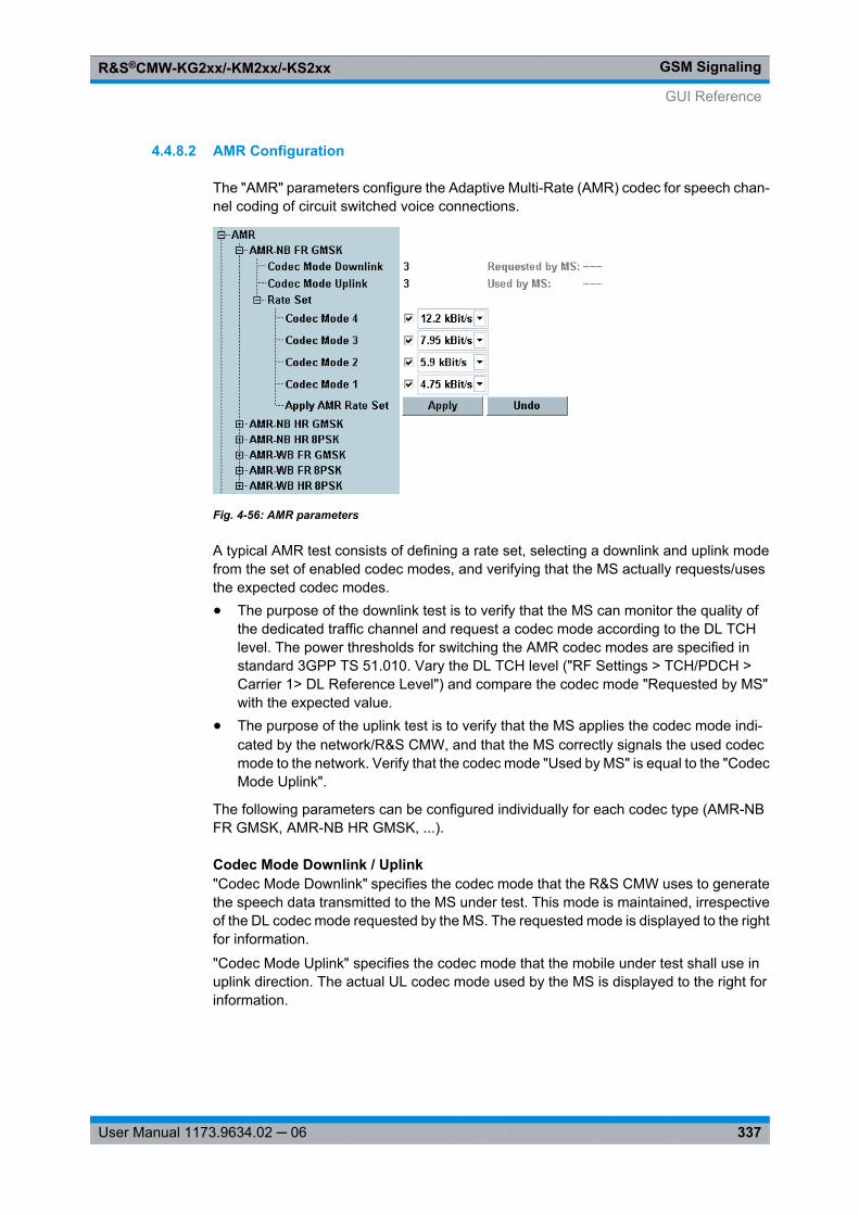
GSM SignalingR&S®CMW-KG2xx/-KM2xx/-KS2xx
337User Manual 1173.9634.02 ─ 06
4.4.8.2 AMR Configuration
The "AMR" parameters configure the Adaptive Multi-Rate (AMR) codec for speech chan-nel coding of circuit switched voice connections.
Fig. 4-56: AMR parameters
A typical AMR test consists of defining a rate set, selecting a downlink and uplink modefrom the set of enabled codec modes, and verifying that the MS actually requests/usesthe expected codec modes.● The purpose of the downlink test is to verify that the MS can monitor the quality of
the dedicated traffic channel and request a codec mode according to the DL TCHlevel. The power thresholds for switching the AMR codec modes are specified instandard 3GPP TS 51.010. Vary the DL TCH level ("RF Settings > TCH/PDCH >Carrier 1> DL Reference Level") and compare the codec mode "Requested by MS"with the expected value.
● The purpose of the uplink test is to verify that the MS applies the codec mode indi-cated by the network/R&S CMW, and that the MS correctly signals the used codecmode to the network. Verify that the codec mode "Used by MS" is equal to the "CodecMode Uplink".
The following parameters can be configured individually for each codec type (AMR-NBFR GMSK, AMR-NB HR GMSK, ...).
Codec Mode Downlink / Uplink"Codec Mode Downlink" specifies the codec mode that the R&S CMW uses to generatethe speech data transmitted to the MS under test. This mode is maintained, irrespectiveof the DL codec mode requested by the MS. The requested mode is displayed to the rightfor information.
"Codec Mode Uplink" specifies the codec mode that the mobile under test shall use inuplink direction. The actual UL codec mode used by the MS is displayed to the right forinformation.
GUI Reference
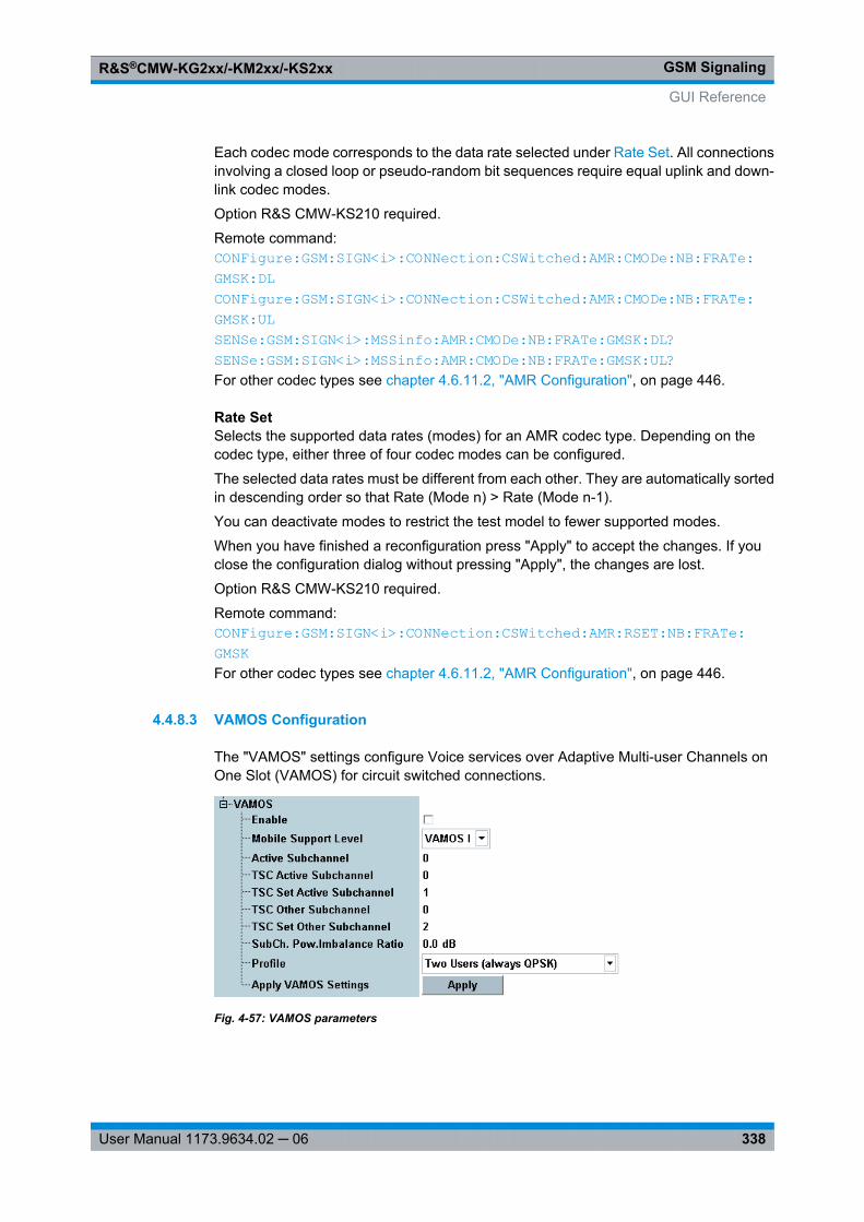
GSM SignalingR&S®CMW-KG2xx/-KM2xx/-KS2xx
338User Manual 1173.9634.02 ─ 06
Each codec mode corresponds to the data rate selected under Rate Set. All connectionsinvolving a closed loop or pseudo-random bit sequences require equal uplink and down-link codec modes.
Option R&S CMW-KS210 required.
Remote command: CONFigure: GSM: SIGN<i>: CONNection: CSWitched: AMR: CMODe: NB: FRATe: GMSK: DL CONFigure: GSM: SIGN<i>: CONNection: CSWitched: AMR: CMODe: NB: FRATe: GMSK: UL SENSe: GSM: SIGN<i>: MSSinfo: AMR: CMODe: NB: FRATe: GMSK: DL? SENSe: GSM: SIGN<i>: MSSinfo: AMR: CMODe: NB: FRATe: GMSK: UL? For other codec types see chapter 4.6.11.2, "AMR Configuration", on page 446.
Rate SetSelects the supported data rates (modes) for an AMR codec type. Depending on thecodec type, either three of four codec modes can be configured.
The selected data rates must be different from each other. They are automatically sortedin descending order so that Rate (Mode n) > Rate (Mode n-1).
You can deactivate modes to restrict the test model to fewer supported modes.
When you have finished a reconfiguration press "Apply" to accept the changes. If youclose the configuration dialog without pressing "Apply", the changes are lost.
Option R&S CMW-KS210 required.
Remote command: CONFigure: GSM: SIGN<i>: CONNection: CSWitched: AMR: RSET: NB: FRATe: GMSK For other codec types see chapter 4.6.11.2, "AMR Configuration", on page 446.
4.4.8.3 VAMOS Configuration
The "VAMOS" settings configure Voice services over Adaptive Multi-user Channels onOne Slot (VAMOS) for circuit switched connections.
Fig. 4-57: VAMOS parameters
GUI Reference
GSM SignalingR&S®CMW-KG2xx/-KM2xx/-KS2xx
339User Manual 1173.9634.02 ─ 06
VAMOS > EnableActivates/deactivates Voice services over Adaptive Multi-user Channels on One Slot(VAMOS).
For background information see chapter 4.2.12.4, "VAMOS", on page 284.
Option R&S CMW-KS203 required.
Remote command: CONFigure: GSM: SIGN<i>: CONNection: CSWitched: VAMos: ENABle
VAMOS > Mobile Support LevelSelects the VAMOS support level of the mobile. The support levels I and II are definedin standard 3GPP TS 45.001, clause 13.2. VAMOS II mobiles must fulfill additional per-formance requirements and use a modified mapping of logical channels onto the physicalchannel, as given in table 1a of 3GPP TS 45.002 (also referred to as "shifted SACCH").
Option R&S CMW-KS203 required.
Remote command: CONFigure: GSM: SIGN<i>: CONNection: CSWitched: VAMos: MSLevel
VAMOS > Active SubchannelSelects the VAMOS subchannel to be used for the DUT. The other subchannel is usedfor the virtual second VAMOS user.
Option R&S CMW-KS203 required.
Remote command: CONFigure: GSM: SIGN<i>: CONNection: CSWitched: VAMos
VAMOS > TSC Active Subchannel / TSC Set Active SubchannelSelect the training sequence to be used for the DUT. The training sequence is identifiedvia the Training Sequence Code (TSC) set and the TSC within this set.
Option R&S CMW-KS203 required.
Remote command: CONFigure: GSM: SIGN<i>: CONNection: CSWitched: VAMos
VAMOS > TSC Other Subchannel / TSC Set Other SubchannelSelect the training sequence to be used for the virtual second VAMOS user. The trainingsequence is identified via the TSC set and the TSC within this set. For a 3GPP compliantconfiguration, select different TSC sets for the DUT and the virtual user.
Option R&S CMW-KS203 required.
Remote command: CONFigure: GSM: SIGN<i>: CONNection: CSWitched: VAMos
VAMOS > SubCh. Pow. Imbalance RatioThe Subchannel Power Imbalance Ratio (SCPIR) defines the power of subchannel 0relative to the power of subchannel 1.
Option R&S CMW-KS203 required.
Remote command: CONFigure: GSM: SIGN<i>: CONNection: CSWitched: VAMos
GUI Reference
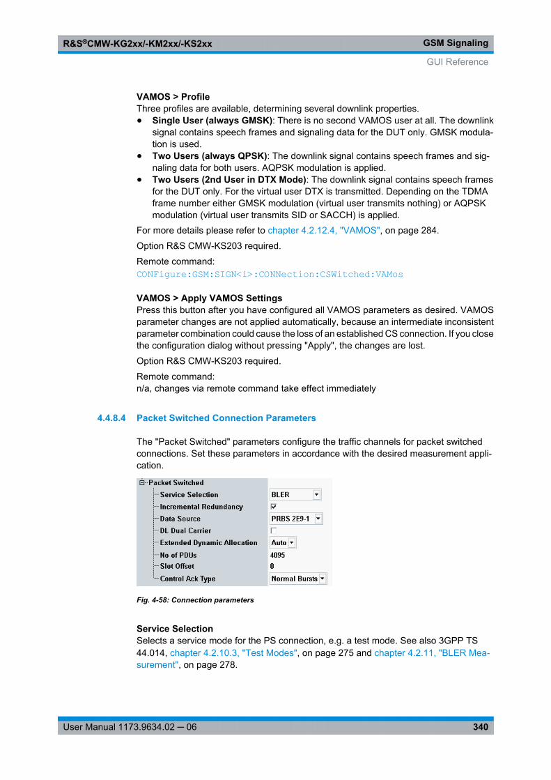
GSM SignalingR&S®CMW-KG2xx/-KM2xx/-KS2xx
340User Manual 1173.9634.02 ─ 06
VAMOS > ProfileThree profiles are available, determining several downlink properties.● Single User (always GMSK): There is no second VAMOS user at all. The downlink
signal contains speech frames and signaling data for the DUT only. GMSK modula-tion is used.
● Two Users (always QPSK): The downlink signal contains speech frames and sig-naling data for both users. AQPSK modulation is applied.
● Two Users (2nd User in DTX Mode): The downlink signal contains speech framesfor the DUT only. For the virtual user DTX is transmitted. Depending on the TDMAframe number either GMSK modulation (virtual user transmits nothing) or AQPSKmodulation (virtual user transmits SID or SACCH) is applied.
For more details please refer to chapter 4.2.12.4, "VAMOS", on page 284.
Option R&S CMW-KS203 required.
Remote command: CONFigure: GSM: SIGN<i>: CONNection: CSWitched: VAMos
VAMOS > Apply VAMOS SettingsPress this button after you have configured all VAMOS parameters as desired. VAMOSparameter changes are not applied automatically, because an intermediate inconsistentparameter combination could cause the loss of an established CS connection. If you closethe configuration dialog without pressing "Apply", the changes are lost.
Option R&S CMW-KS203 required.
Remote command: n/a, changes via remote command take effect immediately
4.4.8.4 Packet Switched Connection Parameters
The "Packet Switched" parameters configure the traffic channels for packet switchedconnections. Set these parameters in accordance with the desired measurement appli-cation.
Fig. 4-58: Connection parameters
Service SelectionSelects a service mode for the PS connection, e.g. a test mode. See also 3GPP TS44.014, chapter 4.2.10.3, "Test Modes", on page 275 and chapter 4.2.11, "BLER Mea-surement", on page 278.
GUI Reference
GSM SignalingR&S®CMW-KG2xx/-KM2xx/-KS2xx
341User Manual 1173.9634.02 ─ 06
"Test Mode A" The MS continuously transmits RLC data blocks containing a pseudorandom data sequence. Recommended for TX tests.
"Test Mode B" The R&S CMW transmits RLC blocks on the downlink containing apseudo random data sequence; the MS loops back the received data.Recommended for BER tests.
"BLER" Full signaling involving the RLC layer for Block Error Ratio (BLER)measurements.
"SRB" EGPRS switched radio block loopback mode for BER tests. The loop-back is performed before channel decoding.
Remote command: CONFigure: GSM: SIGN<i>: CONNection: PSWitched: SERVice
Incremental RedundancyEnables or disables the incremental redundancy RLC mode for the downlink. This modeis used on EGPRS channels to minimize the number of data blocks that have to betransferred repeatedly (retransmitted) until they can be successfully decoded.
With enabled incremental redundancy, the R&S CMW cyclically changes the puncturingscheme if data blocks must be retransmitted. This setting corresponds to normal opera-tion of the BTS in the network and is suitable for incremental redundancy performancetests specified in 3GPP TS 51.010.
With disabled incremental redundancy, the puncturing scheme is fixed. This setting issuitable for layer 1 receiver tests.
Option R&S CMW-KS210 is required.
Remote command: CONFigure: GSM: SIGN<i>: CONNection: PSWitched: IREDundancy
Data SourceSelects the data which the R&S CMW transmits on its DL Packet Data Traffic Channels(PDTCHs).
● PRBS 2E9-1, PRBS 2E11-1:PRBS transmission according to CCITT (ITU-T) O.153
● PRBS 2E15-1:PRBS transmission according to CCITT (ITU-T) O.151
● PRBS 2E16-1:Transmission of a pseudo random bit sequence defined by the polynomial: x16 + x5
+ x3 + x2 + 1Option R&S CMW-KS210 is required.
Remote command: CONFigure: GSM: SIGN<i>: CONNection: PSWitched: DSOurce
DL Dual CarrierEnables or disables the downlink dual carrier mode. In this mode, the R&S CMW usestwo radio frequency channels to assign resources to the mobile station; see 3GPP TS44.060.
GUI Reference
GSM SignalingR&S®CMW-KG2xx/-KM2xx/-KS2xx
342User Manual 1173.9634.02 ─ 06
Some parameters can be configured individually per carrier. For these parameters thereis a "Carrier 1" and a "Carrier 2" setting, see for example "TCH/PDCH > Carrier 1/2 >Channel / Frequency" on page 318 and chapter 4.4.1.7, "Slot Configuration Dialog",on page 305.
Option R&S CMW-KS201 required.
Remote command: CONFigure: GSM: SIGN<i>: CONNection: PSWitched: DLDCarrier: ENABle
Extended Dynamic AllocationExtended dynamic allocation is an optional medium access mode of the mobile (see3GPP TS 44.060). It can be enabled, disabled or automatically enabled if supported bythe mobile. In the latter case the R&S CMW evaluates the GPRS Extended DynamicAllocation message received during GPRS Attach to determine whether the mobile sup-ports extended dynamic allocation or not.
Remote command: CONFigure: GSM: SIGN<i>: CONNection: PSWitched: EDALlocation
No of PDUsNumber of Protocol Data Units (PDU) that the MS is to transmit in the uplink during GPRStest mode A.
If supported by the mobile, a value of 0 can be used to request an "infinite" test modethat is not terminated by the mobile after a certain number of PDUs.
Remote command: CONFigure: GSM: SIGN<i>: CONNection: PSWitched: NOPDus
Slot OffsetTimeslot that is to be taken as the first DL timeslot when the MS is in multislot operation(downlink timeslot offset parameter in the GPRS_TEST_MODE_CMD).
When the mobile loops back data, the slot offset determines which DL slot is looped towhich UL slot. An offset of 0 indicates that a DL slot shall be looped to the UL slot withthe same slot number.
Remote command: CONFigure: GSM: SIGN<i>: CONNection: PSWitched: SOFFset
Control Ack TypeSpecifies whether a mobile sends the PACKET CONTROL ACKNOWLEDGEMENT(3GPP TS 44.060) as four access bursts or as an RLC/MAC Packet Control Acknowl-edgement Control message with four normal bursts.
The "Access Bursts" setting can be used to analyze access bursts while a packet dataconnection is active. The bursts can be analyzed using the "GSM Multi Evaluation" mea-surement (option R&S CMW-KM200).
Remote command: CONFigure: GSM: SIGN<i>: CONNection: PSWitched: CATYpe
GUI Reference
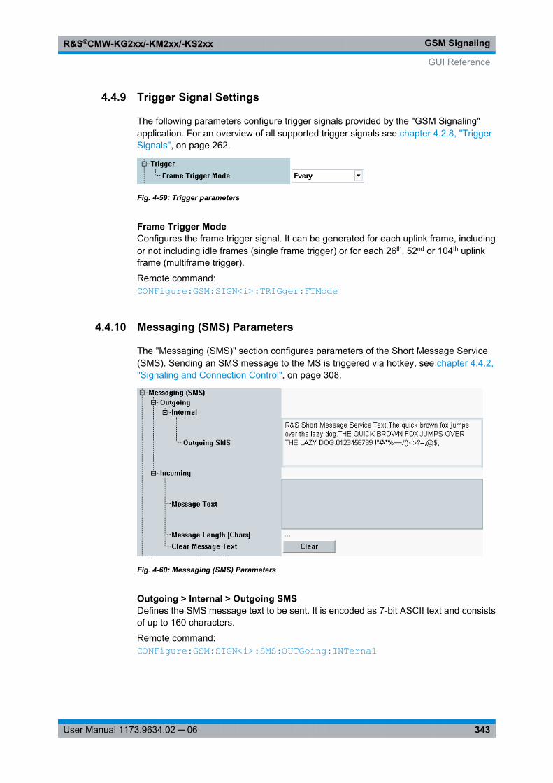
GSM SignalingR&S®CMW-KG2xx/-KM2xx/-KS2xx
343User Manual 1173.9634.02 ─ 06
4.4.9 Trigger Signal Settings
The following parameters configure trigger signals provided by the "GSM Signaling"application. For an overview of all supported trigger signals see chapter 4.2.8, "TriggerSignals", on page 262.
Fig. 4-59: Trigger parameters
Frame Trigger ModeConfigures the frame trigger signal. It can be generated for each uplink frame, includingor not including idle frames (single frame trigger) or for each 26th, 52nd or 104th uplinkframe (multiframe trigger).
Remote command: CONFigure: GSM: SIGN<i>: TRIGger: FTMode
4.4.10 Messaging (SMS) Parameters
The "Messaging (SMS)" section configures parameters of the Short Message Service(SMS). Sending an SMS message to the MS is triggered via hotkey, see chapter 4.4.2,"Signaling and Connection Control", on page 308.
Fig. 4-60: Messaging (SMS) Parameters
Outgoing > Internal > Outgoing SMSDefines the SMS message text to be sent. It is encoded as 7-bit ASCII text and consistsof up to 160 characters.
Remote command: CONFigure: GSM: SIGN<i>: SMS: OUTGoing: INTernal
GUI Reference
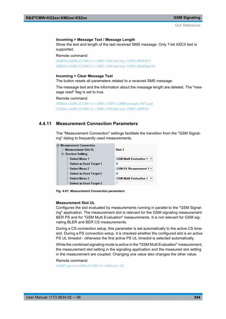
GSM SignalingR&S®CMW-KG2xx/-KM2xx/-KS2xx
344User Manual 1173.9634.02 ─ 06
Incoming > Message Text / Message LengthShow the text and length of the last received SMS message. Only 7-bit ASCII text issupported.
Remote command: SENSe: GSM: SIGN<i>: SMS: INComing: INFO: MTEXt? SENSe: GSM: SIGN<i>: SMS: INComing: INFO: MLENgth?
Incoming > Clear Message TextThe button resets all parameters related to a received SMS message.
The message text and the information about the message length are deleted. The "mes-sage read" flag is set to true.
Remote command: SENSe: GSM: SIGN<i>: SMS: INFO: LRMessage: RFLag? CLEan: GSM: SIGN<i>: SMS: INComing: INFO: MTEXt
4.4.11 Measurement Connection Parameters
The "Measurement Connection" settings facilitate the transition from the "GSM Signal-ing" dialog to frequently used measurements.
Fig. 4-61: Measurement Connection parameters
Measurement Slot ULConfigures the slot evaluated by measurements running in parallel to the "GSM Signal-ing" application. The measurement slot is relevant for the GSM signaling measurementBER PS and for "GSM Multi Evaluation" measurements. It is not relevant for GSM sig-naling BLER and BER CS measurements.
During a CS connection setup, this parameter is set automatically to the active CS time-slot. During a PS connection setup, it is checked whether the configured slot is an activePS UL timeslot - otherwise the first active PS UL timeslot is selected automatically.
While the combined signaling mode is active in the "GSM Multi Evaluation" measurement,the measurement slot setting in the signaling application and the measured slot settingin the measurement are coupled. Changing one value also changes the other value.
Remote command: CONFigure: GSM: SIGN<i>: MSLot: UL
GUI Reference
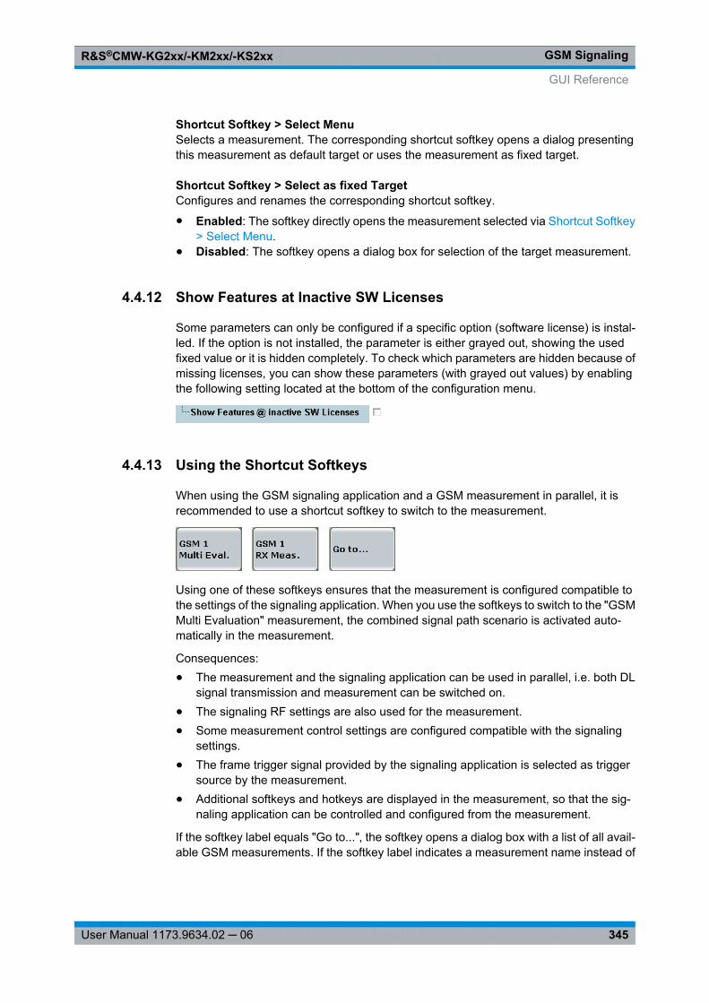
GSM SignalingR&S®CMW-KG2xx/-KM2xx/-KS2xx
345User Manual 1173.9634.02 ─ 06
Shortcut Softkey > Select MenuSelects a measurement. The corresponding shortcut softkey opens a dialog presentingthis measurement as default target or uses the measurement as fixed target.
Shortcut Softkey > Select as fixed TargetConfigures and renames the corresponding shortcut softkey.
● Enabled: The softkey directly opens the measurement selected via Shortcut Softkey> Select Menu.
● Disabled: The softkey opens a dialog box for selection of the target measurement.
4.4.12 Show Features at Inactive SW Licenses
Some parameters can only be configured if a specific option (software license) is instal-led. If the option is not installed, the parameter is either grayed out, showing the usedfixed value or it is hidden completely. To check which parameters are hidden because ofmissing licenses, you can show these parameters (with grayed out values) by enablingthe following setting located at the bottom of the configuration menu.
4.4.13 Using the Shortcut Softkeys
When using the GSM signaling application and a GSM measurement in parallel, it isrecommended to use a shortcut softkey to switch to the measurement.
Using one of these softkeys ensures that the measurement is configured compatible tothe settings of the signaling application. When you use the softkeys to switch to the "GSMMulti Evaluation" measurement, the combined signal path scenario is activated auto-matically in the measurement.
Consequences:● The measurement and the signaling application can be used in parallel, i.e. both DL
signal transmission and measurement can be switched on.● The signaling RF settings are also used for the measurement.● Some measurement control settings are configured compatible with the signaling
settings.● The frame trigger signal provided by the signaling application is selected as trigger
source by the measurement.● Additional softkeys and hotkeys are displayed in the measurement, so that the sig-
naling application can be controlled and configured from the measurement.
If the softkey label equals "Go to...", the softkey opens a dialog box with a list of all avail-able GSM measurements. If the softkey label indicates a measurement name instead of
GUI Reference
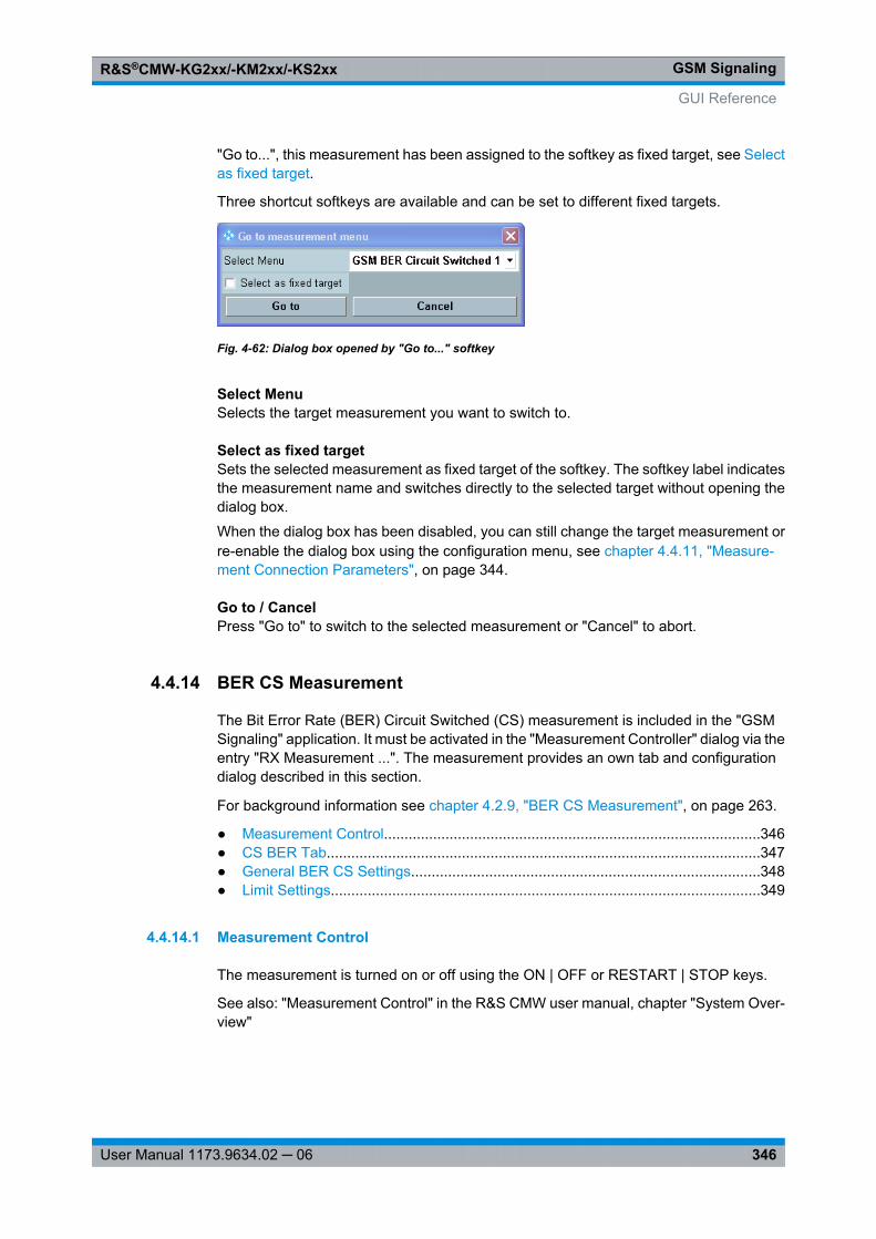
GSM SignalingR&S®CMW-KG2xx/-KM2xx/-KS2xx
346User Manual 1173.9634.02 ─ 06
"Go to...", this measurement has been assigned to the softkey as fixed target, see Selectas fixed target.
Three shortcut softkeys are available and can be set to different fixed targets.
Fig. 4-62: Dialog box opened by "Go to..." softkey
Select MenuSelects the target measurement you want to switch to.
Select as fixed targetSets the selected measurement as fixed target of the softkey. The softkey label indicatesthe measurement name and switches directly to the selected target without opening thedialog box.
When the dialog box has been disabled, you can still change the target measurement orre-enable the dialog box using the configuration menu, see chapter 4.4.11, "Measure-ment Connection Parameters", on page 344.
Go to / CancelPress "Go to" to switch to the selected measurement or "Cancel" to abort.
4.4.14 BER CS Measurement
The Bit Error Rate (BER) Circuit Switched (CS) measurement is included in the "GSMSignaling" application. It must be activated in the "Measurement Controller" dialog via theentry "RX Measurement ...". The measurement provides an own tab and configurationdialog described in this section.
For background information see chapter 4.2.9, "BER CS Measurement", on page 263.
● Measurement Control............................................................................................346● CS BER Tab..........................................................................................................347● General BER CS Settings.....................................................................................348● Limit Settings.........................................................................................................349
4.4.14.1 Measurement Control
The measurement is turned on or off using the ON | OFF or RESTART | STOP keys.
See also: "Measurement Control" in the R&S CMW user manual, chapter "System Over-view"
GUI Reference
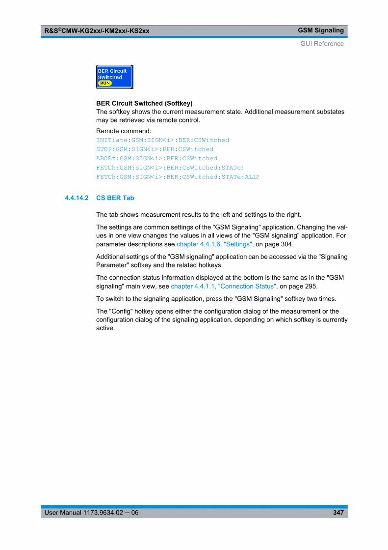
GSM SignalingR&S®CMW-KG2xx/-KM2xx/-KS2xx
347User Manual 1173.9634.02 ─ 06
BER Circuit Switched (Softkey)The softkey shows the current measurement state. Additional measurement substatesmay be retrieved via remote control.
Remote command: INITiate: GSM: SIGN<i>: BER: CSWitched STOP: GSM: SIGN<i>: BER: CSWitched ABORt: GSM: SIGN<i>: BER: CSWitched FETCh: GSM: SIGN<i>: BER: CSWitched: STATe? FETCh: GSM: SIGN<i>: BER: CSWitched: STATe: ALL?
4.4.14.2 CS BER Tab
The tab shows measurement results to the left and settings to the right.
The settings are common settings of the "GSM Signaling" application. Changing the val-ues in one view changes the values in all views of the "GSM signaling" application. Forparameter descriptions see chapter 4.4.1.6, "Settings", on page 304.
Additional settings of the "GSM signaling" application can be accessed via the "SignalingParameter" softkey and the related hotkeys.
The connection status information displayed at the bottom is the same as in the "GSMsignaling" main view, see chapter 4.4.1.1, "Connection Status", on page 295.
To switch to the signaling application, press the "GSM Signaling" softkey two times.
The "Config" hotkey opens either the configuration dialog of the measurement or theconfiguration dialog of the signaling application, depending on which softkey is currentlyactive.
GUI Reference
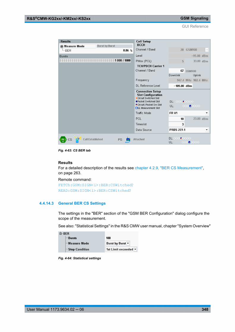
GSM SignalingR&S®CMW-KG2xx/-KM2xx/-KS2xx
348User Manual 1173.9634.02 ─ 06
Fig. 4-63: CS BER tab
ResultsFor a detailed description of the results see chapter 4.2.9, "BER CS Measurement",on page 263.
Remote command: FETCh: GSM: SIGN<i>: BER: CSWitched? READ: GSM: SIGN<i>: BER: CSWitched?
4.4.14.3 General BER CS Settings
The settings in the "BER" section of the "GSM BER Configuration" dialog configure thescope of the measurement.
See also: "Statistical Settings" in the R&S CMW user manual, chapter "System Overview"
Fig. 4-64: Statistical settings
GUI Reference
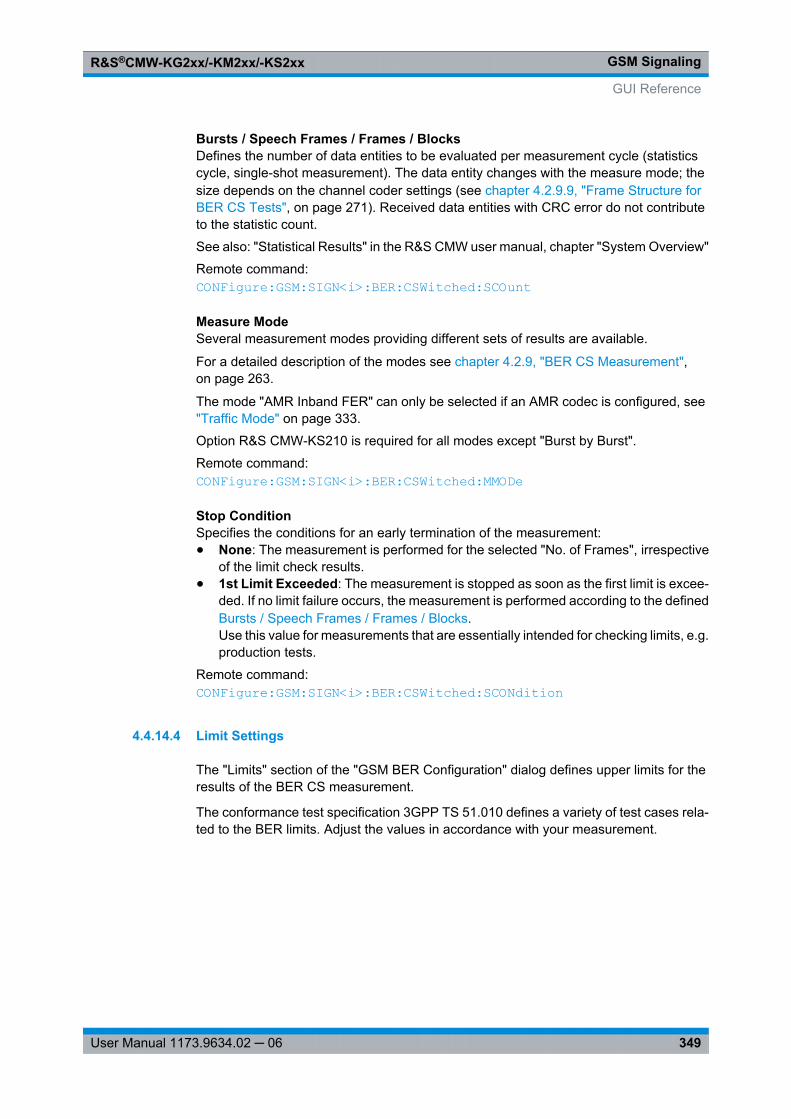
GSM SignalingR&S®CMW-KG2xx/-KM2xx/-KS2xx
349User Manual 1173.9634.02 ─ 06
Bursts / Speech Frames / Frames / BlocksDefines the number of data entities to be evaluated per measurement cycle (statisticscycle, single-shot measurement). The data entity changes with the measure mode; thesize depends on the channel coder settings (see chapter 4.2.9.9, "Frame Structure forBER CS Tests", on page 271). Received data entities with CRC error do not contributeto the statistic count.
See also: "Statistical Results" in the R&S CMW user manual, chapter "System Overview"
Remote command: CONFigure: GSM: SIGN<i>: BER: CSWitched: SCOunt
Measure ModeSeveral measurement modes providing different sets of results are available.
For a detailed description of the modes see chapter 4.2.9, "BER CS Measurement",on page 263.
The mode "AMR Inband FER" can only be selected if an AMR codec is configured, see "Traffic Mode" on page 333.
Option R&S CMW-KS210 is required for all modes except "Burst by Burst".
Remote command: CONFigure: GSM: SIGN<i>: BER: CSWitched: MMODe
Stop ConditionSpecifies the conditions for an early termination of the measurement:● None: The measurement is performed for the selected "No. of Frames", irrespective
of the limit check results.● 1st Limit Exceeded: The measurement is stopped as soon as the first limit is excee-
ded. If no limit failure occurs, the measurement is performed according to the definedBursts / Speech Frames / Frames / Blocks.Use this value for measurements that are essentially intended for checking limits, e.g.production tests.
Remote command: CONFigure: GSM: SIGN<i>: BER: CSWitched: SCONdition
4.4.14.4 Limit Settings
The "Limits" section of the "GSM BER Configuration" dialog defines upper limits for theresults of the BER CS measurement.
The conformance test specification 3GPP TS 51.010 defines a variety of test cases rela-ted to the BER limits. Adjust the values in accordance with your measurement.
GUI Reference
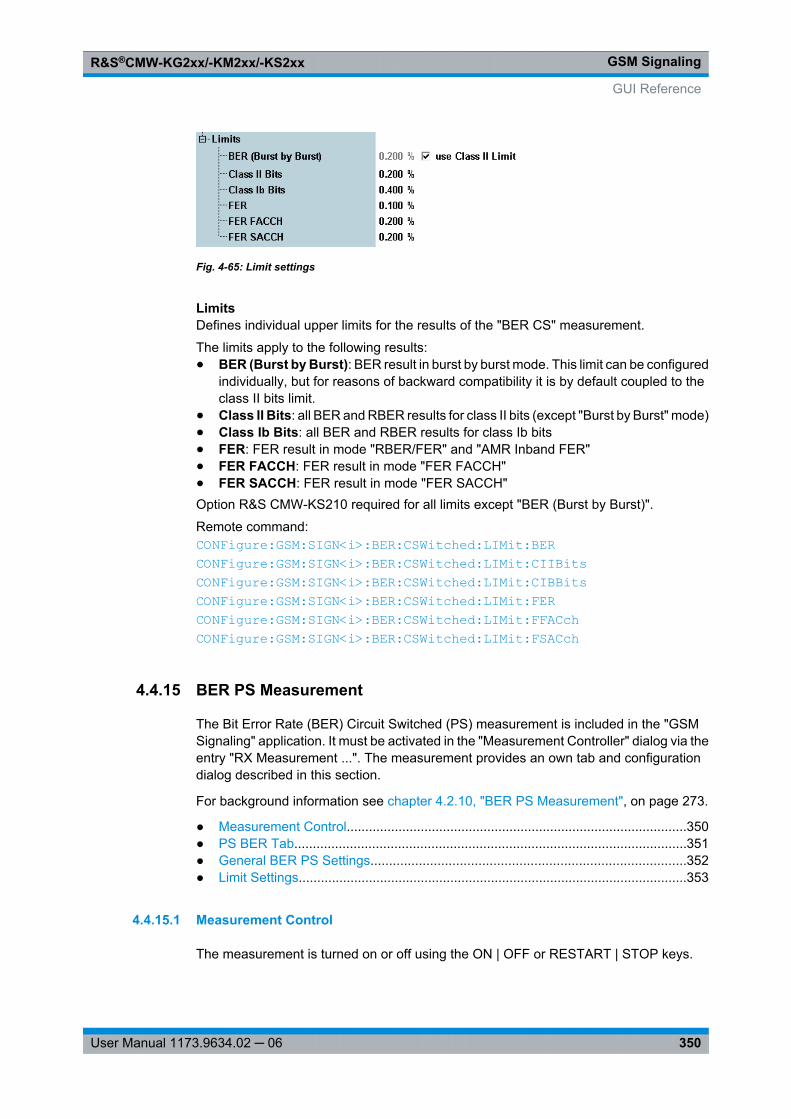
GSM SignalingR&S®CMW-KG2xx/-KM2xx/-KS2xx
350User Manual 1173.9634.02 ─ 06
Fig. 4-65: Limit settings
LimitsDefines individual upper limits for the results of the "BER CS" measurement.
The limits apply to the following results:● BER (Burst by Burst): BER result in burst by burst mode. This limit can be configured
individually, but for reasons of backward compatibility it is by default coupled to theclass II bits limit.
● Class II Bits: all BER and RBER results for class II bits (except "Burst by Burst" mode)● Class Ib Bits: all BER and RBER results for class Ib bits● FER: FER result in mode "RBER/FER" and "AMR Inband FER"● FER FACCH: FER result in mode "FER FACCH"● FER SACCH: FER result in mode "FER SACCH"Option R&S CMW-KS210 required for all limits except "BER (Burst by Burst)".
Remote command: CONFigure: GSM: SIGN<i>: BER: CSWitched: LIMit: BER CONFigure: GSM: SIGN<i>: BER: CSWitched: LIMit: CIIBits CONFigure: GSM: SIGN<i>: BER: CSWitched: LIMit: CIBBits CONFigure: GSM: SIGN<i>: BER: CSWitched: LIMit: FER CONFigure: GSM: SIGN<i>: BER: CSWitched: LIMit: FFACch CONFigure: GSM: SIGN<i>: BER: CSWitched: LIMit: FSACch
4.4.15 BER PS Measurement
The Bit Error Rate (BER) Circuit Switched (PS) measurement is included in the "GSMSignaling" application. It must be activated in the "Measurement Controller" dialog via theentry "RX Measurement ...". The measurement provides an own tab and configurationdialog described in this section.
For background information see chapter 4.2.10, "BER PS Measurement", on page 273.
● Measurement Control............................................................................................350● PS BER Tab..........................................................................................................351● General BER PS Settings.....................................................................................352● Limit Settings.........................................................................................................353
4.4.15.1 Measurement Control
The measurement is turned on or off using the ON | OFF or RESTART | STOP keys.
GUI Reference
GSM SignalingR&S®CMW-KG2xx/-KM2xx/-KS2xx
351User Manual 1173.9634.02 ─ 06
See also: "Measurement Control" in the R&S CMW user manual, chapter "System Over-view"
BER Packet Switched (Softkey)The softkey shows the current measurement state. Additional measurement substatesmay be retrieved via remote control.
Remote command: INITiate: GSM: SIGN<i>: BER: PSWitched STOP: GSM: SIGN<i>: BER: PSWitched ABORt: GSM: SIGN<i>: BER: PSWitched FETCh: GSM: SIGN<i>: BER: PSWitched: STATe? FETCh: GSM: SIGN<i>: BER: PSWitched: STATe: ALL?
4.4.15.2 PS BER Tab
The tab shows measurement results to the left and settings to the right.
The settings are common settings of the "GSM Signaling" application. Changing the val-ues in one view changes the values in all views of the "GSM signaling" application. Forparameter descriptions see chapter 4.4.1.6, "Settings", on page 304.
Additional settings of the "GSM signaling" application can be accessed via the "SignalingParameter" softkey and the related hotkeys.
The connection status information displayed at the bottom is the same as in the "GSMsignaling" main view, see chapter 4.4.1.1, "Connection Status", on page 295.
To switch to the signaling application, press the "GSM Signaling" softkey two times.
The "Config" hotkey opens either the configuration dialog of the measurement or theconfiguration dialog of the signaling application, depending on which softkey is currentlyactive.
GUI Reference
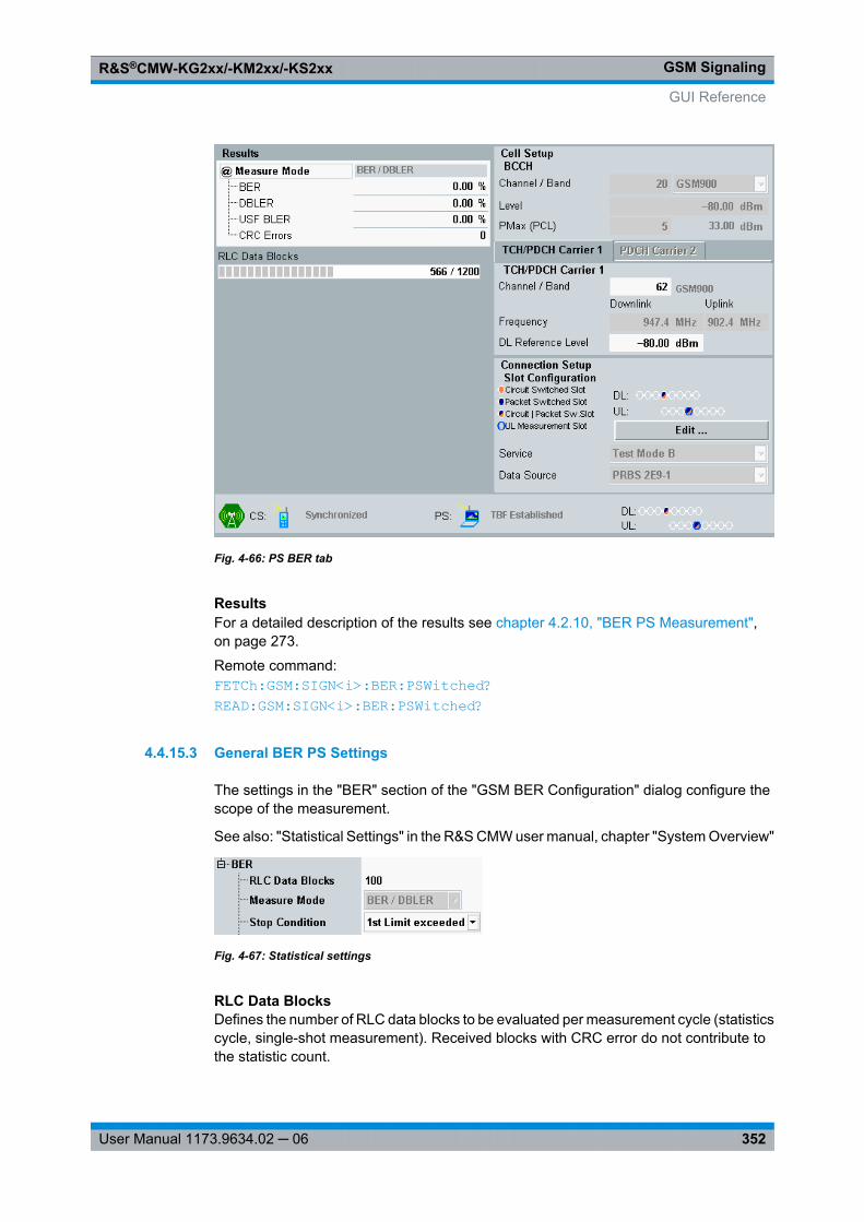
GSM SignalingR&S®CMW-KG2xx/-KM2xx/-KS2xx
352User Manual 1173.9634.02 ─ 06
Fig. 4-66: PS BER tab
ResultsFor a detailed description of the results see chapter 4.2.10, "BER PS Measurement",on page 273.
Remote command: FETCh: GSM: SIGN<i>: BER: PSWitched? READ: GSM: SIGN<i>: BER: PSWitched?
4.4.15.3 General BER PS Settings
The settings in the "BER" section of the "GSM BER Configuration" dialog configure thescope of the measurement.
See also: "Statistical Settings" in the R&S CMW user manual, chapter "System Overview"
Fig. 4-67: Statistical settings
RLC Data BlocksDefines the number of RLC data blocks to be evaluated per measurement cycle (statisticscycle, single-shot measurement). Received blocks with CRC error do not contribute tothe statistic count.
GUI Reference
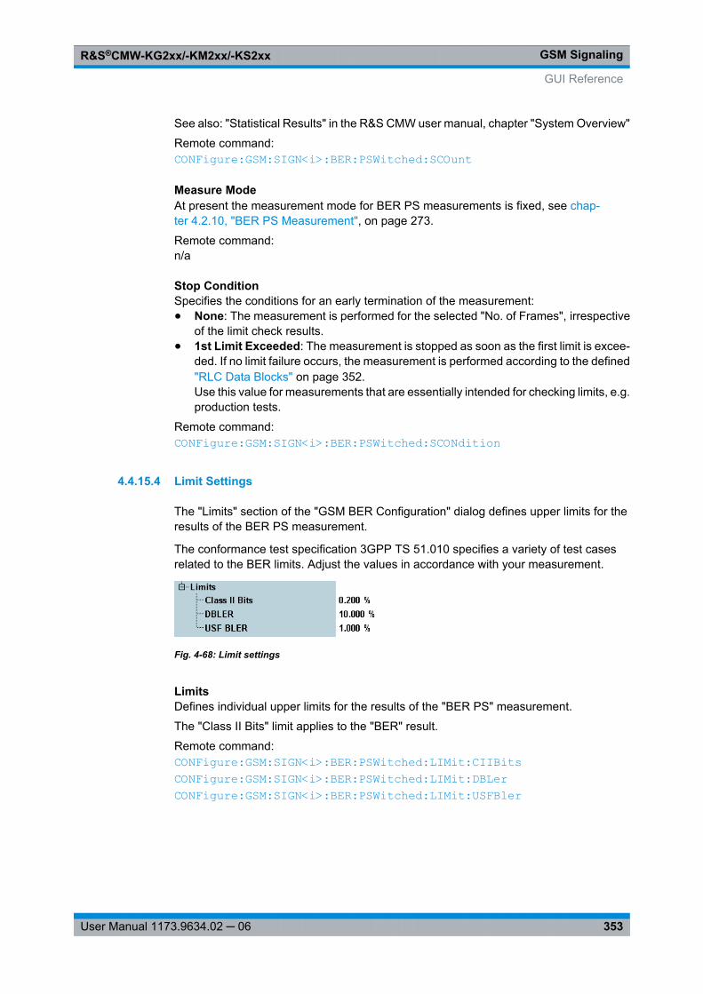
GSM SignalingR&S®CMW-KG2xx/-KM2xx/-KS2xx
353User Manual 1173.9634.02 ─ 06
See also: "Statistical Results" in the R&S CMW user manual, chapter "System Overview"
Remote command: CONFigure: GSM: SIGN<i>: BER: PSWitched: SCOunt
Measure ModeAt present the measurement mode for BER PS measurements is fixed, see chap-ter 4.2.10, "BER PS Measurement", on page 273.
Remote command: n/a
Stop ConditionSpecifies the conditions for an early termination of the measurement:● None: The measurement is performed for the selected "No. of Frames", irrespective
of the limit check results.● 1st Limit Exceeded: The measurement is stopped as soon as the first limit is excee-
ded. If no limit failure occurs, the measurement is performed according to the defined"RLC Data Blocks" on page 352.Use this value for measurements that are essentially intended for checking limits, e.g.production tests.
Remote command: CONFigure: GSM: SIGN<i>: BER: PSWitched: SCONdition
4.4.15.4 Limit Settings
The "Limits" section of the "GSM BER Configuration" dialog defines upper limits for theresults of the BER PS measurement.
The conformance test specification 3GPP TS 51.010 specifies a variety of test casesrelated to the BER limits. Adjust the values in accordance with your measurement.
Fig. 4-68: Limit settings
LimitsDefines individual upper limits for the results of the "BER PS" measurement.
The "Class II Bits" limit applies to the "BER" result.
Remote command: CONFigure: GSM: SIGN<i>: BER: PSWitched: LIMit: CIIBits CONFigure: GSM: SIGN<i>: BER: PSWitched: LIMit: DBLer CONFigure: GSM: SIGN<i>: BER: PSWitched: LIMit: USFBler
GUI Reference
GSM SignalingR&S®CMW-KG2xx/-KM2xx/-KS2xx
354User Manual 1173.9634.02 ─ 06
4.4.16 BLER Measurement
The Block Error Rate (BLER) measurement is included in the "GSM Signaling" applica-tion. It must be activated in the "Measurement Controller" dialog via the entry "RX Mea-surement ...". The measurement provides an own tab and configuration dialog describedin this section.
For background information see chapter 4.2.11, "BLER Measurement", on page 278.
● Measurement Control............................................................................................354● PS BLER Tab........................................................................................................354● Statistical Settings.................................................................................................355
4.4.16.1 Measurement Control
The measurement is turned on or off using the ON | OFF or RESTART | STOP keys.
See also: "Measurement Control" in the R&S CMW user manual, chapter "System Over-view"
BLER (Softkey)The softkey shows the current measurement state. Additional measurement substatesmay be retrieved via remote control.
Remote command: INITiate: GSM: SIGN<i>: BLER STOP: GSM: SIGN<i>: BLER ABORt: GSM: SIGN<i>: BLER FETCh: GSM: SIGN<i>: BLER: STATe? FETCh: GSM: SIGN<i>: BLER: STATe: ALL?
4.4.16.2 PS BLER Tab
The tab shows measurement results to the left and settings to the right.
The settings are common settings of the "GSM Signaling" application. Changing the val-ues in one view changes the values in all views of the "GSM signaling" application. Forparameter descriptions see chapter 4.4.1.6, "Settings", on page 304.
Additional settings of the "GSM signaling" application can be accessed via the "SignalingParameter" softkey and the related hotkeys.
The connection status information displayed at the bottom is the same as in the "GSMsignaling" main view, see chapter 4.4.1.1, "Connection Status", on page 295.
To switch to the signaling application, press the "GSM Signaling" softkey two times.
GUI Reference
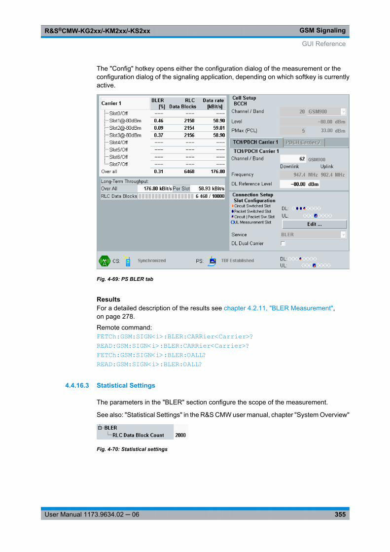
GSM SignalingR&S®CMW-KG2xx/-KM2xx/-KS2xx
355User Manual 1173.9634.02 ─ 06
The "Config" hotkey opens either the configuration dialog of the measurement or theconfiguration dialog of the signaling application, depending on which softkey is currentlyactive.
Fig. 4-69: PS BLER tab
ResultsFor a detailed description of the results see chapter 4.2.11, "BLER Measurement",on page 278.
Remote command: FETCh: GSM: SIGN<i>: BLER: CARRier<Carrier>? READ: GSM: SIGN<i>: BLER: CARRier<Carrier>? FETCh: GSM: SIGN<i>: BLER: OALL? READ: GSM: SIGN<i>: BLER: OALL?
4.4.16.3 Statistical Settings
The parameters in the "BLER" section configure the scope of the measurement.
See also: "Statistical Settings" in the R&S CMW user manual, chapter "System Overview"
Fig. 4-70: Statistical settings
GUI Reference
GSM SignalingR&S®CMW-KG2xx/-KM2xx/-KS2xx
356User Manual 1173.9634.02 ─ 06
RLC Data Block CountDefines the number of RLC data blocks to be evaluated per measurement cycle (statisticscycle, single-shot measurement). The number of blocks sent can be larger than thespecified value because blocks may be lost on the way to the mobile.
Remote command: CONFigure: GSM: SIGN<i>: BLER: SCOunt
4.5 Programming
The following sections provide programming examples for the GSM signaling application.
The examples contain SCPI commands supported by the R&S CMW and the followingsymbolic scripting commands:● // <comment>:
A <comment> ignored by the used programming tool● WHILE <query> <> <value>:
Waits until the <query> returns a certain <value>, e.g. a specific state is reached.● WAITKEY <message>:
Displays a dialog box with a <message> and waits until the box is closed by the user.
See also: "Remote Control" in the R&S CMW user manual
● Signaling Application.............................................................................................356● BER CS Measurements........................................................................................370● BER PS Measurement..........................................................................................373● BLER Measurement..............................................................................................374
4.5.1 Signaling Application
The GSM signaling application is programmed as follows:● The application is controlled by SCPI commands with the following syn-
tax: ...:GSM:SIGN:...● After a *RST, the DL signal is switched off.
To activate the DL signal use SOURce:GSM:SIGN:CELL:STATe ON.Query the cell state using SOURce:GSM:SIGN:CELL:STATe:ALL?. The resultON,ADJ indicates that the DL signal is available.
● To initiate a connection setup in the CS domain useCALL:GSM:SIGN:CSWitched:ACTion CONNect.To initiate a connection setup in the PS domain, useCALL:GSM:SIGN:PSWitched:ACTion CONNect.To query the connection states use FETCh:GSM:SIGN:CSWitched:STATe? andFETCh:GSM:SIGN:PSWitched:STATe?.
The following sections describe how to configure the signaling application.
Programming
GSM SignalingR&S®CMW-KG2xx/-KM2xx/-KS2xx
357User Manual 1173.9634.02 ─ 06
The subsequent sections describe how to switch on the cell signal and the MS and howto set up a CS or PS connection. Some examples for actions possible after connectionsetup are also given.
● Specifying General Settings..................................................................................357● Configuring BCCH, TCH and PDCH.....................................................................358● Configuring Internal Fading...................................................................................359● Configuring Network and MS Identities.................................................................359● Configuring Requested Mobile Data.....................................................................360● Configuring Cell Parameters.................................................................................360● Setting Timers and Constants...............................................................................361● Configuring Security Settings................................................................................361● Configuring General CS Connection Settings.......................................................361● Configuring AMR Settings.....................................................................................362● Configuring VAMOS Support................................................................................363● Configuring PS Connection Settings.....................................................................364● Configuring Trigger Signals...................................................................................365● Switching on the Cell Signal and the MS..............................................................365● Configuring the I/Q Settings..................................................................................365● Querying MS Info..................................................................................................365● Querying MS Capabilities......................................................................................366● Setting up a CS Connection..................................................................................366● Retrieving CS Receiver Reports...........................................................................366● Sending / Receiving an SMS................................................................................367● Sending Date and Time Information to the MS.....................................................367● Performing an Intra-GSM CS Handover...............................................................368● Setting up a PS Connection..................................................................................368● Retrieving PS Receiver Reports...........................................................................368● Performing an Intra-GSM PS Handover................................................................369
4.5.1.1 Specifying General Settings
// *****************************************************************************// System-Reset// ******************************************************************************RST; *OPC?*CLS; *OPC?
// *****************************************************************************// Enable a connection to the DAU.// *****************************************************************************CONFigure:GSM:SIGN:ETOE ON
// *****************************************************************************// Define paths for a standard cell with or without external fading,// including signal routing and external attenuation.// ROUTe commands also activate the scenario. Send only one of the two commands.// *****************************************************************************ROUTe:GSM:SIGN:SCENario:SCELl RF2C,RX1,RF2C,TX1ROUTe:GSM:SIGN:SCENario:SCFading RF2C,RX1,RF2C,TX1,IQ2O
Programming
GSM SignalingR&S®CMW-KG2xx/-KM2xx/-KS2xx
358User Manual 1173.9634.02 ─ 06
CONFigure:GSM:SIGN:RFSettings:EATTenuation:OUTPut 2CONFigure:GSM:SIGN:RFSettings:EATTenuation:INPut 2
// *****************************************************************************// Define input and output paths for the "BCCH and TCH/PDCH" scenario.// *****************************************************************************ROUTe:GSM:SIGN:SCENario:BATCh RF1C,RX1,RF1C,TX1,RF3C,TX2CONFigure:GSM:SIGN:RFSettings:EATTenuation:INPut 2CONFigure:GSM:SIGN:RFSettings:EATTenuation:OUTPut1 2CONFigure:GSM:SIGN:RFSettings:EATTenuation:BCCH:OUTPut 2
// *****************************************************************************// Statically configure the expected uplink power:// - choose manual expected nominal power mode// - set the expected nominal power to 23 dBm and apply a margin of 7 dB // *****************************************************************************CONFigure:GSM:SIGN:RFSettings:ENPMode MANualCONFigure:GSM:SIGN:RFSettings:ENPower 23CONFigure:GSM:SIGN:RFSettings:UMARgin 7
4.5.1.2 Configuring BCCH, TCH and PDCH
// *****************************************************************************// Define the cell's BCCH:// - GSM 900 band, channel 20// - maximum allowed MS output power 33 dBm (PCL 5)// - level -80 dBm// *****************************************************************************CONFigure:GSM:SIGN:BAND:BCCH G09CONFigure:GSM:SIGN:RFSettings:CHANnel:BCCH 20CONFigure:GSM:SIGN:RFSettings:PMAX:BCCH 5CONFigure:GSM:SIGN:RFSettings:LEVel:BCCH -80
// *****************************************************************************// Set the traffic channel no to 62 and the DL reference level to -80 dBm.// *****************************************************************************CONFigure:GSM:SIGN:RFSettings:CHANnel:TCH 62CONFigure:GSM:SIGN:RFSettings:LEVel:TCH -80
// *****************************************************************************// Set the power control level for the uplink to 10, which corresponds to// an absolute level of -23 dBm in the GSM 900 band.// *****************************************************************************CONFigure:GSM:SIGN:RFSettings:PCL:TCH:CSWitched 10
// *****************************************************************************// Configure frequency hopping: specify the hopping sequence, // the Mobile Allocation Index Offset (MAIO)// and the Hopping Sequence Number (HSN); enable frequency hopping.
Programming
GSM SignalingR&S®CMW-KG2xx/-KM2xx/-KS2xx
359User Manual 1173.9634.02 ─ 06
// *****************************************************************************CONFigure:GSM:SIGN:RFSettings:HOPPing:SEQuence:TCH 1,62,124CONFigure:GSM:SIGN:RFSettings:HOPPing:MAIO:TCH 0CONFigure:GSM:SIGN:RFSettings:HOPPing:HSN:TCH 0CONFigure:GSM:SIGN:RFSettings:HOPPing:ENABle:TCH
4.5.1.3 Configuring Internal Fading
// *****************************************************************************// Select a standard cell scenario with internal fading.// *****************************************************************************ROUTe:GSM:SIGN:SCENario:SCFading:INTernal:FFADer RF2C,RX1,RF2C,TX1
// *****************************************************************************// Configure the fading simulator:// Enable it, select a fading profile, start fading automatically,// set start seed and calculate insertion loss automatically.// *****************************************************************************CONFigure:GSM:SIGN:FADing:FSIMulator:ENABle ONCONFigure:GSM:SIGN:FADing:FSIMulator:STANdard T3CONFigure:GSM:SIGN:FADing:FSIMulator:RESTart:MODE AUTOCONFigure:GSM:SIGN:FADing:FSIMulator:GLOBal:SEED 0CONFigure:GSM:SIGN:FADing:FSIMulator:ILOSs:MODE NORMal
// *****************************************************************************// Configure AWGN insertion:// Enable AWGN, set min noise/system BW ratio, set signal to noise ratio// and query calculated noise power.// *****************************************************************************CONFigure:GSM:SIGN:FADing:AWGN:ENABle ONCONFigure:GSM:SIGN:FADing:AWGN:BWIDth:RATio 1CONFigure:GSM:SIGN:FADing:AWGN:SNRatio 1CONFigure:GSM:SIGN:FADing:POWer:NOISe?
4.5.1.4 Configuring Network and MS Identities
// *****************************************************************************// Query the cell identity.// *****************************************************************************CONFigure:GSM:SIGN:CELL:IDENtity?
// *****************************************************************************// Identify the cell's PLMN:// - set the mobile country code to 1// - set the mobile network code length to 2 and the value to 1// *****************************************************************************CONFigure:GSM:SIGN:CELL:MCC 1CONFigure:GSM:SIGN:CELL:MNC:DIGits TWOCONFigure:GSM:SIGN:CELL:MNC 1
Programming
GSM SignalingR&S®CMW-KG2xx/-KM2xx/-KS2xx
360User Manual 1173.9634.02 ─ 06
// *****************************************************************************// Identify the cell's area within the PLMN:// - set the location area code to 1// - set the routing area code to 0// *****************************************************************************CONFigure:GSM:SIGN:CELL:LAC 1CONFigure:GSM:SIGN:CELL:RAC 0
// *****************************************************************************// Configure the Base Station Identity Code (BSIC):// - set the network color code to 0// - set the BS colour code to 0// *****************************************************************************CONFigure:GSM:SIGN:CELL:NCC 0CONFigure:GSM:SIGN:CELL:BCC 0
// *****************************************************************************// Configure the default IMSI.// *****************************************************************************CONFigure:GSM:SIGN:CELL:IMSI 1,1,1000000095
4.5.1.5 Configuring Requested Mobile Data
// *****************************************************************************// Tell the MS to send its IMEI during location / routing area updates.// *****************************************************************************CONFigure:GSM:SIGN:CELL:IMEirequest ON
4.5.1.6 Configuring Cell Parameters
// *****************************************************************************// General settings: Define number of AGCH data blocks reserved for AGCH access,// set interval between two paging requests, tell mobile to determine channel// numbers in the GSM 1800 band.// *****************************************************************************CONFigure:GSM:SIGN:CELL:BSAGblksres 0CONFigure:GSM:SIGN:CELL:BSPamfrms 2CONFigure:GSM:SIGN:CELL:BINDicator G18
// *****************************************************************************// CS settings: Tell mobile to perform a location update whenever it is// switched on, don't allow DTX.// *****************************************************************************CONFigure:GSM:SIGN:CELL:LUPDate ALWaysCONFigure:GSM:SIGN:CELL:DTX OFF
// *****************************************************************************// PS settings: Select channel type used by mobile to determine received signal
Programming
GSM SignalingR&S®CMW-KG2xx/-KM2xx/-KS2xx
361User Manual 1173.9634.02 ─ 06
// strength and quality, accept PDP context activation attempts from the MS,// specify signal level filter period for power control and BEP period.// *****************************************************************************CONFigure:GSM:SIGN:CELL:PSWitched:PCMChannel BCCHCONFigure:GSM:SIGN:CELL:PSWitched:PDPContext ACCeptCONFigure:GSM:SIGN:CELL:PSWitched:TAVGtw 3CONFigure:GSM:SIGN:CELL:PSWitched:BPERiod 1
4.5.1.7 Setting Timers and Constants
// *****************************************************************************// Set the radio link timeout on the MS and BS // to 24 missing SACCH blocks (~11.5 s).// *****************************************************************************CONFigure:GSM:SIGN:CELL:RTMS 24CONFigure:GSM:SIGN:CELL:RTBS 24
// *****************************************************************************// Specify the timeout for unanswered mobile-terminating calls.// *****************************************************************************CONFigure:GSM:SIGN:CELL:ATIMeout
// *****************************************************************************// Tell the mobile // - to perform a periodic location update every 6 minutes (Timer T3212) // - not to perform periodic routing area updates (Timer T3312)// *****************************************************************************CONFigure:GSM:SIGN:CELL:PLUPdate 1CONFigure:GSM:SIGN:CELL:PRAupdate 0
4.5.1.8 Configuring Security Settings
// *****************************************************************************// Enable authentication, define secret key and select SIM card type.// *****************************************************************************CONFigure:GSM:SIGN:CELL:SECurity:AUTHenticat ONCONFigure:GSM:SIGN:CELL:SECurity:SKEY #H000102030405060708090A0B0C0D0E0FCONFigure:GSM:SIGN:CELL:SECurity:SIMCard C2G
4.5.1.9 Configuring General CS Connection Settings
// *****************************************************************************// Set the timeslot for circuit switched calls;// (optionally) set the uplink slot for GSM measurement applications.// *****************************************************************************CONFigure:GSM:SIGN:CONNection:CSWitched:TSLot 3CONFigure:GSM:SIGN:MSLot:UL 3
Programming
GSM SignalingR&S®CMW-KG2xx/-KM2xx/-KS2xx
362User Manual 1173.9634.02 ─ 06
// *****************************************************************************// Select the AMR narrowband half-rate GMSK codec for voice calls and use// subchannel 1.// *****************************************************************************CONFigure:GSM:SIGN:CONNection:CSWitched:TMODe ANHGCONFigure:GSM:SIGN:CONNection:CSWitched:HRSubchannel 1
// *****************************************************************************// Select PRBS 2E9-1 as data source.// *****************************************************************************CONFigure:GSM:SIGN:CONNection:CSWitched:DSOurce PR9
// *****************************************************************************// Enable a TCH burst-by-burst loop that is re-closed after channel change.// *****************************************************************************CONFigure:GSM:SIGN:CONNection:CSWitched:LOOP CCONFigure:GSM:SIGN:CONNection:CSWitched:LREClose ON
// *****************************************************************************// Set the caller Id.// *****************************************************************************CONFigure:GSM:SIGN:CONNection:CSWitched:CID 00498941290
// *****************************************************************************// Configure late traffic channel assignment (off-air call setup).// *****************************************************************************CONFigure:GSM:SIGN:CONNection:CSWitched:TCHassign LATE
4.5.1.10 Configuring AMR Settings
// *****************************************************************************// Configure rate sets for different AMR types.// *****************************************************************************CONF:GSM:SIGN:CONN:CSWitched:AMR:RSET:NB:FRATe:GMSK C1220,C0795,C0590,C0475CONF:GSM:SIGN:CONN:CSWitched:AMR:RSET:NB:HRATe:GMSK OFF,OFF,C0795,C0515CONF:GSM:SIGN:CONN:CSWitched:AMR:RSET:NB:HRATe:EPSK OFF,C1220,C0795,C0590CONF:GSM:SIGN:CONN:CSWitched:AMR:RSET:WB:FRATe:GMSK OFF,C0885,C0660CONF:GSM:SIGN:CONN:CSWitched:AMR:RSET:WB:FRATe:EPSK OFF,C2385,C1585,C1265CONF:GSM:SIGN:CONN:CSWitched:AMR:RSET:WB:HRATe:EPSK OFF,C1265,C0885
// *****************************************************************************// Specify the initial codec modes.// *****************************************************************************CONFigure:GSM:SIGN:CONNection:CSWitched:AMR:CMODe:NB:FRATe:GMSK:DL 3CONFigure:GSM:SIGN:CONNection:CSWitched:AMR:CMODe:NB:FRATe:GMSK:UL 3CONFigure:GSM:SIGN:CONNection:CSWitched:AMR:CMODe:NB:HRATe:GMSK:DL 2CONFigure:GSM:SIGN:CONNection:CSWitched:AMR:CMODe:NB:HRATe:GMSK:UL 2CONFigure:GSM:SIGN:CONNection:CSWitched:AMR:CMODe:NB:HRATe:EPSK:DL 3CONFigure:GSM:SIGN:CONNection:CSWitched:AMR:CMODe:NB:HRATe:EPSK:UL 3
Programming
GSM SignalingR&S®CMW-KG2xx/-KM2xx/-KS2xx
363User Manual 1173.9634.02 ─ 06
CONFigure:GSM:SIGN:CONNection:CSWitched:AMR:CMODe:WB:FRATe:GMSK:DL 2CONFigure:GSM:SIGN:CONNection:CSWitched:AMR:CMODe:WB:FRATe:GMSK:UL 2CONFigure:GSM:SIGN:CONNection:CSWitched:AMR:CMODe:WB:FRATe:EPSK:DL 2CONFigure:GSM:SIGN:CONNection:CSWitched:AMR:CMODe:WB:FRATe:EPSK:UL 2CONFigure:GSM:SIGN:CONNection:CSWitched:AMR:CMODe:WB:HRATe:EPSK:DL 2CONFigure:GSM:SIGN:CONNection:CSWitched:AMR:CMODe:WB:HRATe:EPSK:UL 2
// *****************************************************************************// Query the DL codec modes requested by the MS (DL) and the actual codec modes // used by the MS (UL).// *****************************************************************************SENSe:GSM:SIGN:MSSinfo:AMR:CMODe:NB:FRATe:GMSK:DL?SENSe:GSM:SIGN:MSSinfo:AMR:CMODe:NB:FRATe:GMSK:UL?SENSe:GSM:SIGN:MSSinfo:AMR:CMODe:NB:HRATe:GMSK:DL?SENSe:GSM:SIGN:MSSinfo:AMR:CMODe:NB:HRATe:GMSK:UL?SENSe:GSM:SIGN:MSSinfo:AMR:CMODe:NB:HRATe:EPSK:DL?SENSe:GSM:SIGN:MSSinfo:AMR:CMODe:NB:HRATe:EPSK:UL?SENSe:GSM:SIGN:MSSinfo:AMR:CMODe:WB:FRATe:GMSK:DL?SENSe:GSM:SIGN:MSSinfo:AMR:CMODe:WB:FRATe:GMSK:UL?SENSe:GSM:SIGN:MSSinfo:AMR:CMODe:WB:FRATe:EPSK:DL?SENSe:GSM:SIGN:MSSinfo:AMR:CMODe:WB:FRATe:EPSK:UL?SENSe:GSM:SIGN:MSSinfo:AMR:CMODe:WB:HRATe:EPSK:DL?SENSe:GSM:SIGN:MSSinfo:AMR:CMODe:WB:HRATe:EPSK:UL?
4.5.1.11 Configuring VAMOS Support
// *****************************************************************************// Set the VAMOS support level that is required from the mobile.// *****************************************************************************CONFigure:GSM:SIGN:CONNection:CSWitched:VAMos:MSLevel VAM1
// *****************************************************************************// Perform all VAMOS settings:// - VAMOS subchannel = 0// - TSC for active subchannel = 0// - TSC set for active subchannel = 1// - TSC for other (virtual) subchannel = 0// - TSC set for other (virtual) subchannel = 2// - Subchannel power imbalance ratio = 0 dB// - VAMOS profile = "Two active VAMOS users"// *****************************************************************************CONFigure:GSM:SIGN:CONNection:CSWitched:VAMos 0,0,1,0,2,0,TUS
// *****************************************************************************// Enable VAMOS.// *****************************************************************************CONFigure:GSM:SIGN:CONNection:CSWitched:VAMos:ENABle ON
Programming
GSM SignalingR&S®CMW-KG2xx/-KM2xx/-KS2xx
364User Manual 1173.9634.02 ─ 06
4.5.1.12 Configuring PS Connection Settings
// *****************************************************************************// Enable the "Packet Switched Domain" and disable dual carrier mode.// *****************************************************************************CONFigure:GSM:SIGN:CELL:PSDomain ONCONFigure:GSM:SIGN:CONNection:PSWitched:DLDCarrier:ENABle OFF
// *****************************************************************************// Select "Test Mode B" (PRBS test data looped back at MS) as service mode,// enable incremental redundancy, select a pseudo-random bit sequence,// no extended dynamic allocation, the number of PDUs,// the slot offset for the loopback data and the burst type for CTRL_ACK// messages.// *****************************************************************************CONFigure:GSM:SIGN:CONNection:PSWitched:SERVice TMBCONFigure:GSM:SIGN:CONNection:PSWitched:IREDundancy ONCONFigure:GSM:SIGN:CONNection:PSWitched:DSOurce PR9CONFigure:GSM:SIGN:CONNection:PSWitched:EDALlocation OFFCONFigure:GSM:SIGN:CONNection:PSWitched:NOPDus 4095CONFigure:GSM:SIGN:CONNection:PSWitched:SOFFset 0CONFigure:GSM:SIGN:CONNection:PSWitched:CATYpe NBURsts
// *****************************************************************************// Select EGPRS as transmission scheme.// *****************************************************************************CONFigure:GSM:SIGN:CONNection:PSWitched:TLEVel EGPRS
// *****************************************************************************// Select MCS-1 as UL coding scheme.// *****************************************************************************CONFigure:GSM:SIGN:CONNection:PSWitched:CSCHeme:UL MC1
// *****************************************************************************// Use slots 1 and 2 for the uplink and slots 4, 5, 6 and 7 for the downlink.// *****************************************************************************CONF:GSM:SIGN:CONN:PSWitched:SCONfig:ENABle:UL OFF,ON,ON,OFF,OFF,OFF,OFF,OFFCONF:GSM:SIGN:CONN:PSWitched:SCONfig:ENABle:DL:CARR OFF,OFF,OFF,OFF,ON,ON,ON,ON
// *****************************************************************************// Configure the power in all uplink and downlink slots.// *****************************************************************************CONF:GSM:SIGN:CONN:PSWitched:SCONfig:GAMMa:UL 13,13,13,13,13,13,13,13CONF:GSM:SIGN:CONN:PSWitched:SCONfig:LEVel:DL:CARRier -5,-5,-5,-5,-5,-5,-5,-5
// *****************************************************************************// Configure the coding schemes on the downlink.// *****************************************************************************CONF:GSM:SIGN:CONN:PSW:SCON:CSCHeme:DL:CARRier MC1,MC1,MC1,MC1,MC1,MC1,MC1,MC1
Programming
GSM SignalingR&S®CMW-KG2xx/-KM2xx/-KS2xx
365User Manual 1173.9634.02 ─ 06
// *****************************************************************************// Query the resulting maximum RLC throughput.// *****************************************************************************SENSe:GSM:SIGN:CONNection:ETHRoughput:DL?SENSe:GSM:SIGN:CONNection:ETHRoughput:UL?
4.5.1.13 Configuring Trigger Signals
// *****************************************************************************// Configure the frame trigger signal so that a trigger pulse is generated// at the start of every frame.// *****************************************************************************CONFigure:GSM:SIGN:TRIGger:FTMode EVERy
4.5.1.14 Switching on the Cell Signal and the MS
// *****************************************************************************// Physically connect the MS (switched off), then switch on the DL signal. // Query the cell state until it equals ON,ADJ // (i.e. the DL signal is available at the RF connector).// ***************************************************************************** WAITKEY >Ensure that the MS is connected to the instrument and switched off<SOURce:GSM:SIGN:CELL:STATe ONWHILE SOURce:GSM:SIGN:CELL:STATe:ALL? <> "ON,ADJ"
// ***************************************************************************** // Switch on the MS and wait until it is synchronized and attached.// Make sure that the PS domain is enabled at all.// ***************************************************************************** WAITKEY >Switch on the MS<WHILE FETCh:GSM:SIGN:CSWitched:STATe? <> "SYNC"WHILE FETCh:GSM:SIGN:PSWitched:STATe? <> "ATT"
4.5.1.15 Configuring the I/Q Settings
// ***************************************************************************** // Query the properties of the outgoing baseband signal, required to configure// the baseband input of the connected instrument. Configure the baseband input// according to the baseband output of the connected instrument.// ***************************************************************************** SENSe:GSM:SIGN:IQOut:PATH?CONFigure:GSM:SIGN:IQIN:PATH -30, -20
4.5.1.16 Querying MS Info
// ***************************************************************************** // Ask for the IMEI and IMSI of the MS.// *****************************************************************************
Programming
GSM SignalingR&S®CMW-KG2xx/-KM2xx/-KS2xx
366User Manual 1173.9634.02 ─ 06
SENSe:GSM:SIGN:MSSinfo:IMEI?SENSe:GSM:SIGN:MSSinfo:IMSI?
// ***************************************************************************** // Ask for the dialed number.// ***************************************************************************** WAITKEY >Initiate a mobile originating call at the UE<SENSe:GSM:SIGN:MSSinfo:DNUMber?
4.5.1.17 Querying MS Capabilities
// ***************************************************************************** // Ask for the bands supported by the MS.// ***************************************************************************** SENSe:GSM:SIGN:MSSinfo:BANDs?
// ***************************************************************************** // Ask for the supported GPRS/EGPRS multislot classes // in single and dual transfer mode.// ***************************************************************************** SENSe:GSM:SIGN:MSSinfo:MSCLass:GPRS?SENSe:GSM:SIGN:MSSinfo:MSCLass:EGPRs?SENSe:GSM:SIGN:MSSinfo:MSCLass:DGPRs?SENSe:GSM:SIGN:MSSinfo:MSCLass:DEGPrs?
// ***************************************************************************** // Query support of extended dynamic allocation.// ***************************************************************************** SENSe:GSM:SIGN:MSSinfo:EDALlocation?
4.5.1.18 Setting up a CS Connection
// ***************************************************************************** // Set up a mobile terminating connection.// Query the connection state until it equals CEST (call established).// ***************************************************************************** CALL:GSM:SIGN:CSWitched:ACTion CONNectWHILE FETCh:GSM:SIGN:CSWitched:STATe? <> "CEST"
4.5.1.19 Retrieving CS Receiver Reports
// ***************************************************************************** // Retrieve RX level measurement reports: index values and corresponding ranges.// ***************************************************************************** SENSe:GSM:SIGN:RREPort:RXLevel?SENSe:GSM:SIGN:RREPort:RXLevel:RANGe?SENSe:GSM:SIGN:RREPort:RXLevel:SUB?SENSe:GSM:SIGN:RREPort:RXLevel:SUB:RANGe?
Programming
GSM SignalingR&S®CMW-KG2xx/-KM2xx/-KS2xx
367User Manual 1173.9634.02 ─ 06
// ***************************************************************************** // Retrieve quality measurement reports: index values and corresponding ranges.// *****************************************************************************SENSe:GSM:SIGN:RREPort:RXQuality?SENSe:GSM:SIGN:RREPort:RXQuality:RANGe?SENSe:GSM:SIGN:RREPort:RXQuality:SUB?SENSe:GSM:SIGN:RREPort:RXQuality:SUB:RANGe?
// ***************************************************************************** // Query the number of received reports.// *****************************************************************************SENSe:GSM:SIGN:RREPort:COUNt?
4.5.1.20 Sending / Receiving an SMS
// *****************************************************************************// Prepare an outgoing SMS and send the message.// *****************************************************************************CONFigure:GSM:SIGN:SMS:OUTGoing:INTernal "Hello world!"CALL:GSM:SIGN:CSWitched:ACTion SMS
// *****************************************************************************// Query the state of the "message read" flag.// *****************************************************************************SENSe:GSM:SIGN:SMS:INFO:LRMessage:RFLag?
// *****************************************************************************// If the query returns OFF, there is an unread message. In this case ask // for the message's length and text (for further processing).// *****************************************************************************SENSe:GSM:SIGN:SMS:INComing:INFO:MLENgth?SENSe:GSM:SIGN:SMS:INComing:INFO:MTEXt?
// *****************************************************************************// Clean the incoming message buffer (and reset the "message read" flag).// *****************************************************************************CLEan:GSM:SIGN:SMS:INComing:INFO:MTEXt
4.5.1.21 Sending Date and Time Information to the MS
// ***************************************************************************** // Select a time source and configure date, time and DST +1h.// Send the information to the MS.// ***************************************************************************** CONFigure:GSM:SIGN:CELL:TIME:TSOurce DATECONFigure:GSM:SIGN:CELL:TIME:DATE 24,10,2012CONFigure:GSM:SIGN:CELL:TIME:TIME 12,40,30
Programming
GSM SignalingR&S®CMW-KG2xx/-KM2xx/-KS2xx
368User Manual 1173.9634.02 ─ 06
CONFigure:GSM:SIGN:CELL:TIME:DSTime P1HCONFigure:GSM:SIGN:CELL:TIME:SNOW
4.5.1.22 Performing an Intra-GSM CS Handover
// *****************************************************************************// For the target cell configure:// - GSM 1800 band, channel 711// - a level of -80 dBm// - a power control level index of 10 (corresponds to 10 dBm) // *****************************************************************************PREPare:GSM:SIGN:HANDover:TARGet G18PREPare:GSM:SIGN:HANDover:CHANnel:TCH 711PREPare:GSM:SIGN:HANDover:LEVel:TCH -80PREPare:GSM:SIGN:HANDover:PCL 10PREPare:GSM:SIGN:HANDover:TSLot 3
// *****************************************************************************// Initiate the handover.// *****************************************************************************CALL:GSM:SIGN:HANDover:STARt
// *****************************************************************************// Check whether the handover has been performed successfully:// result must be CEST, otherwise the handover has failed// *****************************************************************************FETCh:GSM:SIGN:CSWitched:STATe?
4.5.1.23 Setting up a PS Connection
// ***************************************************************************** // Set up a PS connection.// Query the connection state until the connection has been established.// Query the IPv4 address assigned to the MS.// ***************************************************************************** CALL:GSM:SIGN:PSWitched:ACTion CONNectWHILE FETCh:GSM:SIGN:PSWitched:STATe? <> TBFSENSe:GSM:SIGN:MSSinfo:MSADdress:IPV4?
4.5.1.24 Retrieving PS Receiver Reports
// ***************************************************************************** // Retrieve the "C value" (i.e. the measured average carrier level) and the // signal variance: query for index values and corresponding ranges.// ***************************************************************************** SENSe:GSM:SIGN:RREPort:CVALue?SENSe:GSM:SIGN:RREPort:CVALue:RANGe?SENSe:GSM:SIGN:RREPort:SVARiance?
Programming
GSM SignalingR&S®CMW-KG2xx/-KM2xx/-KS2xx
369User Manual 1173.9634.02 ─ 06
SENSe:GSM:SIGN:RREPort:SVARiance:RANGe?
// ***************************************************************************** // Retrieve the mean bit error probability (MEAN_BEP) and the coefficient of// variation of the bit error probability (CV_BEP) for the individual// modulation types:// GMSK, 8PSK, 16-QAM/32-QAM with normal and higher symbol rate// ***************************************************************************** SENSe:GSM:SIGN:RREPort:GMBep?SENSe:GSM:SIGN:RREPort:GMBep:RANGe?SENSe:GSM:SIGN:RREPort:GCBep?SENSe:GSM:SIGN:RREPort:GCBep:RANGe?
SENSe:GSM:SIGN:RREPort:EMBep?SENSe:GSM:SIGN:RREPort:EMBep:RANGe?SENSe:GSM:SIGN:RREPort:ECBep?SENSe:GSM:SIGN:RREPort:ECBep:RANGe?
SENSe:GSM:SIGN:RREPort:NSRQam16:MBEP?SENSe:GSM:SIGN:RREPort:NSRQam16:MBEP:RANGe?SENSe:GSM:SIGN:RREPort:NSRQam16:CBEP?SENSe:GSM:SIGN:RREPort:NSRQam16:CBEP:RANGe?SENSe:GSM:SIGN:RREPort:NSRQam32:MBEP?SENSe:GSM:SIGN:RREPort:NSRQam32:MBEP:RANGe?SENSe:GSM:SIGN:RREPort:NSRQam32:CBEP?SENSe:GSM:SIGN:RREPort:NSRQam32:CBEP:RANGe?
SENSe:GSM:SIGN:RREPort:HSRQam16:MBEP?SENSe:GSM:SIGN:RREPort:HSRQam16:MBEP:RANGe?SENSe:GSM:SIGN:RREPort:HSRQam16:CBEP?SENSe:GSM:SIGN:RREPort:HSRQam16:CBEP:RANGe?SENSe:GSM:SIGN:RREPort:HSRQam32:MBEP?SENSe:GSM:SIGN:RREPort:HSRQam32:MBEP:RANGe?SENSe:GSM:SIGN:RREPort:HSRQam32:CBEP?SENSe:GSM:SIGN:RREPort:HSRQam32:CBEP:RANGe?
4.5.1.25 Performing an Intra-GSM PS Handover
// *****************************************************************************// For the target cell configure:// - GSM 1800 band, channel 711// - MCS-2 as UL coding scheme// - a DL reference level of -80 dBm// *****************************************************************************PREPare:GSM:SIGN:HANDover:TARGet G18PREPare:GSM:SIGN:HANDover:CHANnel:TCH 711PREPare:GSM:SIGN:HAND:PSW:CSCHeme:UL MC2PREPare:GSM:SIGN:HANDover:LEVel:TCH -80
Programming
GSM SignalingR&S®CMW-KG2xx/-KM2xx/-KS2xx
370User Manual 1173.9634.02 ─ 06
// *****************************************************************************// Specify the slot configuration for the target cell (single carrier).// *****************************************************************************PREPare:GSM:SIGN:HANDover:PSWitched:ENABle:UL OFF,OFF,ON,OFF,OFF,OFF,OFF,OFFPREPare:GSM:SIGN:HANDover:PSWitched:GAMMa:UL 13,13,13,13,13,13,13,13PREPare:GSM:SIGN:HAND:PSW:ENABle:DL:CARRier OFF,OFF,ON,OFF,OFF,OFF,OFF,OFFPREPare:GSM:SIGN:HANDover:PSWitched:LEVel:DL:CARRier -5,-5,-5,-5,-5,-5,-5,-5PREPare:GSM:SIGN:HAND:PSW:CSCHeme:DL:CARRier MC2,MC2,MC2,MC2,MC2,MC2,MC2,MC2
// *****************************************************************************// Initiate the handover.// *****************************************************************************CALL:GSM:SIGN:HANDover:STARt
// *****************************************************************************// Check whether the handover has been performed successfully:// result must be TBF, otherwise the handover has failed// *****************************************************************************FETCh:GSM:SIGN:PSWitched:STATe?
4.5.2 BER CS Measurements
BER measurements for circuit switched connections are performed usingthe ...GSM:SIGN:BER:CSWitched... commands. The required test loops for BERCS measurements are set implicitly by the measurement mode.
4.5.2.1 Measuring in Burst by Burst Mode
Before proceeding, configure the signaling application (band, channel, power levels,slots ...) and set up a circuit switched connection.
// *****************************************************************************// Set the number of bursts to be measured to 100 and the measurement mode to// "Burst by Burst".// *****************************************************************************CONFigure:GSM:SIGN:BER:CSWitched:MMODe BBBCONFigure:GSM:SIGN:BER:CSWitched:SCOunt 100
// *****************************************************************************// Tell the BER measurement to stop if the BER limit (the only limit for this // measurement mode) is exceeded; set this limit to 0.2%.// *****************************************************************************CONFigure:GSM:SIGN:BER:CSWitched:SCONdition FLIMCONFigure:GSM:SIGN:BER:CSWitched:LIMit:BER 0.2
// *****************************************************************************// Initiate the measurement and retrieve the results.
Programming
GSM SignalingR&S®CMW-KG2xx/-KM2xx/-KS2xx
371User Manual 1173.9634.02 ─ 06
// *****************************************************************************READ:GSM:SIGN:BER:CSWitched?
4.5.2.2 Measuring in BER Mode
Before proceeding, configure the signaling application and set up a circuit switched con-nection.
// *****************************************************************************// Set the number of speech frames to be measured to 100 and the// measurement mode to BER.// *****************************************************************************CONFigure:GSM:SIGN:BER:CSWitched:MMODe BERCONFigure:GSM:SIGN:BER:CSWitched:SCOunt 100
// *****************************************************************************// Set the error rate limits for Class II and Class Ib bits to 0.2% and 0.4%.// Tell the BER Measurement to stop if one of these limits is exceeded. // *****************************************************************************CONFigure:GSM:SIGN:BER:CSWitched:LIMit:CIIBits 0.2CONFigure:GSM:SIGN:BER:CSWitched:LIMit:CIBBits 0.4CONFigure:GSM:SIGN:BER:CSWitched:SCONdition FLIM
// *****************************************************************************// Initiate the measurement and retrieve the results.// *****************************************************************************READ:GSM:SIGN:BER:CSWitched?
4.5.2.3 Measuring in RBER/FER Mode
Before proceeding, configure the signaling application and set up a circuit switched con-nection.
// *****************************************************************************// Set number of speech frames to 100 and measurement mode to "RBER/FER".// *****************************************************************************CONFigure:GSM:SIGN:BER:CSWitched:MMODe RFERCONFigure:GSM:SIGN:BER:CSWitched:SCOunt 100
// *****************************************************************************// Set the residual bit error rate limits for Class II and Class Ib bits to 0.2% // and 0.4%, respectively; set the Frame Erasure Ratio (FER) limit to 0.1%. // Tell the BER measurement not to stop when a limit is exceeded.// *****************************************************************************CONFigure:GSM:SIGN:BER:CSWitched:LIMit:CIIBits 0.2CONFigure:GSM:SIGN:BER:CSWitched:LIMit:CIBBits 0.4CONFigure:GSM:SIGN:BER:CSWitched:LIMit:FER 0.1CONFigure:GSM:SIGN:BER:CSWitched:SCONdition NONE
// *****************************************************************************
Programming
GSM SignalingR&S®CMW-KG2xx/-KM2xx/-KS2xx
372User Manual 1173.9634.02 ─ 06
// Initiate the measurement and retrieve the results.// *****************************************************************************READ:GSM:SIGN:BER:CSWitched?
4.5.2.4 Measuring in FER FACCH and FER SACCH Mode
// *****************************************************************************// Re-configure the DL generator for repeated FACCH and repeated SACCH // transmission. A previous CS connection must be closed, e.g. by means of an // instrument reset. // Set PCL = 7 to ensure an appropriate initial power for the FER SCCCH test.// ******************************************************************************RST...CONFigure:GSM:SIGN:CONNection:CSWitched:RFACch ONCONFigure:GSM:SIGN:CONNection:CSWitched:RSACch ONCONFigure:GSM:SIGN:RFSettings:PCL:TCH:CSWitched 7
WAITKEY >Set up a CS connection via the signaling application<
// *****************************************************************************// Set the Frame Error Rate (FER) limits to 0.1%. // Tell the BER Measurement not to stop when a limit is exceeded.// *****************************************************************************CONFigure:GSM:SIGN:BER:CSWitched:LIMit:FFACch 0.1CONFigure:GSM:SIGN:BER:CSWitched:LIMit:FSACch 0.1CONFigure:GSM:SIGN:BER:CSWitched:SCONdition NONE
// *****************************************************************************// Set the measurement mode to "FER FACCH" and the number of repeated L2 frames // to 100. Initiate the measurement and retrieve the results.// *****************************************************************************CONFigure:GSM:SIGN:BER:CSWitched:MMODe FFACchCONFigure:GSM:SIGN:BER:CSWitched:SCOunt 100READ:GSM:SIGN:BER:CSWitched?
// *****************************************************************************// Set the measurement mode to "FER SACCH" and the number of repeated SACCH // frames to 200. Initiate the measurement and retrieve the results. // *****************************************************************************CONFigure:GSM:SIGN:BER:CSWitched:MMODe FSACchCONFigure:GSM:SIGN:BER:CSWitched:SCOunt 100READ:GSM:SIGN:BER:CSWitched?
4.5.2.5 Measuring in AMR Inband FER Mode
Before proceeding, configure the signaling application and set up a circuit switched con-nection.
Programming
GSM SignalingR&S®CMW-KG2xx/-KM2xx/-KS2xx
373User Manual 1173.9634.02 ─ 06
// *****************************************************************************// Select an AMR codec (e.g. AMR narrowband half-rate GMSK).// *****************************************************************************CONFigure:GSM:SIGN:CONNection:CSWitched:TMODe ANHG
// *****************************************************************************// Set number of speech frames to 100 and measurement mode to "AMR Inband FER".// *****************************************************************************CONFigure:GSM:SIGN:BER:CSWitched:MMODe AIFerCONFigure:GSM:SIGN:BER:CSWitched:SCOunt 100
// *****************************************************************************// Set the FER limit to 0.5%.// Tell the BER measurement not to stop when a limit is exceeded.// *****************************************************************************CONFigure:GSM:SIGN:BER:CSWitched:LIMit:FER 0.5CONFigure:GSM:SIGN:BER:CSWitched:SCONdition NONE
// *****************************************************************************// Initiate the measurement and retrieve the results.// *****************************************************************************READ:GSM:SIGN:BER:CSWitched?
4.5.3 BER PS Measurement
// *****************************************************************************// Configure the signaling application (band, channel, power levels, slots ...).// Select service "Test Mode B" to obtain the full set of measurement results.// *****************************************************************************...CONFigure:GSM:SIGN:CONNection:PSWitched:SERVice TMB
// *****************************************************************************// Set coding scheme for UL and downlink to MCS-1.// *****************************************************************************CONFigure:GSM:SIGN:CONNection:PSWitched:CSCHeme:UL MC1CONF:GSM:SIGN:CONN:PSW:SCON:CSCHeme:DL:CARRier MC1,MC1,MC1,MC1,MC1,MC1,MC1,MC1
// *****************************************************************************// Set the number of bursts to be measured to 100.// *****************************************************************************CONFigure:GSM:SIGN:BER:PSWitched:SCOunt 100
// *****************************************************************************// Set the error rate limit for Class II bits to 0.2%, // the Data Block Error Rate (DBLER) limit to 10% and // the Uplink State Flag Block Error Rate (USF BLER) to 1%.// Tell the BER measurement to stop if one of these limits is exceeded. // *****************************************************************************
Programming
GSM SignalingR&S®CMW-KG2xx/-KM2xx/-KS2xx
374User Manual 1173.9634.02 ─ 06
CONFigure:GSM:SIGN:BER:PSWitched:LIMit:CIIBits 0.2CONFigure:GSM:SIGN:BER:PSWitched:LIMit:DBLer 10CONFigure:GSM:SIGN:BER:PSWitched:LIMit:USFBler 1CONFigure:GSM:SIGN:BER:PSWitched:SCONdition FLIM
// *****************************************************************************// Set up a packet switched connection.// Initiate the measurement and retrieve the results.// *****************************************************************************WAITKEY >Set up a PS connection via the signaling application<READ:GSM:SIGN:BER:PSWitched?
4.5.4 BLER Measurement
// *****************************************************************************// Configure the signaling application (band, channel, power levels, slots ...).// Service "BLER" is required for this measurement.// *****************************************************************************...CONFigure:GSM:SIGN:CONNection:PSWitched:SERVice BLER
// *****************************************************************************// Set the number of blocks to be measured to 2000.// *****************************************************************************CONFigure:GSM:SIGN:BLER:SCOunt 2000
// *****************************************************************************// Set up a packet switched connection.// Initiate the measurement and retrieve overall and slot-specific results.// *****************************************************************************WAITKEY >Set up a PS connection via the signaling application<READ:GSM:SIGN:BLER:OALL?READ:GSM:SIGN:BLER:CARRier?
4.6 Command Reference
The following sections provide detailed reference information on the remote control com-mands of the "GSM Signaling" application.
● Conventions and General Information..................................................................375● General Settings...................................................................................................378● Connection Control and States.............................................................................378● Event Log..............................................................................................................382● Signaling Information............................................................................................383● Slot Configuration and Resulting Throughput.......................................................399● Handover...............................................................................................................404● Routing Settings....................................................................................................409
Command Reference
GSM SignalingR&S®CMW-KG2xx/-KM2xx/-KS2xx
375User Manual 1173.9634.02 ─ 06
● Internal Fading......................................................................................................425● Network Settings...................................................................................................430● Connection Settings..............................................................................................442● Trigger Signal Settings..........................................................................................458● Messaging (SMS)..................................................................................................459● Measurement Slot Settings...................................................................................461● BER CS Measurement..........................................................................................461● BER PS Measurement..........................................................................................468● BLER Measurement..............................................................................................473
4.6.1 Conventions and General Information
The following sections describe the most important conventions and general informationsconcerning the command reference.
4.6.1.1 SIGN<i>
SIGN<i> is used as abbreviation of "SIGNaling<instance>". For better readability onlythe abbreviated form (which is also accepted by the instrument) is given in the commandreference.
The <instance> is relevant for instruments supporting several instances of the samefirmware application. It can be omitted if the instrument supports only one instance, or toaddress the first instance.
See also: "Firmware Applications" in the R&S CMW user manual, chapter "Remote Con-trol"
4.6.1.2 FETCh and READ Commands
All commands are used to retrieve measurement results:● FETCh... returns the results of the current measurement cycle (single-shot mea-
surement) after they are valid. FETCh... must be used after the measurement hasbeen started (INITiate..., measurement states RUN or RDY).
● READ... starts a new single-shot measurement and returns the results.
See also: "Retrieving Measurement Results" in the R&S CMW user manual, chapter"Remote Control"
4.6.1.3 Reliability Indicator
The first value in the output arrays of FETCh...?, READ...? and CALCulate...?queries indicates the most severe error that has occurred during the measurement.
Example for an output array: 0, 10.22, 10.15, 10.01, 10.29, 100 (reliability = 0, followedby 5 numeric measurement values).
The reliability indicator has one of the following values:● 0 (OK):
Command Reference
GSM SignalingR&S®CMW-KG2xx/-KM2xx/-KS2xx
376User Manual 1173.9634.02 ─ 06
Measurement values available, no error detected.● 1 (Measurement Timeout):
The measurement has been stopped after the (configurable) measurement timeout.Measurement results may be available, however, at least a part of the measurementprovides only INValid results or has not completed the full statistic count.
● 2 (Capture Buffer Overflow):The measurement configuration results in a capture length exceeding the availablememory.
● 3 (Overdriven) / 4 (Underdriven):The accuracy of measurement results may be impaired because the input signal levelwas too high / too low.
● 6 (Trigger Timeout):The measurement could not be started or continued because no trigger event wasdetected.
● 7 (Acquisition Error):The R&S CMW could not properly decode the RF input signal.
● 8 (Sync Error):The R&S CMW could not synchronize to the RF input signal.
● 9 (Uncal):Due to an inappropriate configuration of resolution bandwidth, video bandwidth orsweep time, the measurement results are not within the specified data sheet limits.
● 15 (Reference Frequency Error):The instrument has been configured to use an external reference signal but the ref-erence oscillator could not be phase locked to the external signal (e.g. signal leveltoo low, frequency out of range or reference signal not available at all).
● 16 (RF Not Available):The measurement could not be started because the configured RF input path wasnot active. This problem may occur e.g. when a measurement is started in combinedsignal path mode and the master application has not yet activated the input path. TheLEDs above the RF connectors indicate whether the input and output paths areactive.
● 17 (RF Level not Settled) / 18 (RF Frequency not Settled):The measurement could not be started because the R&S CMW was not yet ready todeliver stable results after a change of the input signal power / the input signal fre-quency.
● 19 (Call not Established):For measurements: The measurement could not be started because no signalingconnection to the DUT was established.For DAU IMS service: Establishing a voice over IMS call failed.
● 20 (Call Type not Usable):For measurements: The measurement could not be started because the establishedsignaling connection had wrong properties.For DAU IMS service: The voice over IMS settings could not be applied.
● 21 (Call Lost):For measurements: The measurement was interrupted because the signaling con-nection to the DUT was lost.For DAU IMS service: The voice over IMS call was lost.
Command Reference
GSM SignalingR&S®CMW-KG2xx/-KM2xx/-KS2xx
377User Manual 1173.9634.02 ─ 06
● 23 (Missing Option):The ARB file can not be played by the GPRF generator due to a missing option.
● 26 (Resource Conflict):The application could not be started or has been stopped due to a conflicting hard-ware resource or software option that is allocated by another application.Please stop the application that has allocated the conflicting resources and try again.
● 27 (No Sensor Connected):The GPRF External Power Sensor measurement could not be started due to missingpower sensor.
● 40 (ARB File CRC Error):The ARB file CRC check failed. The ARB file is corrupt and not reliable.
● 42 (ARB Header Tag Invalid):The ARB file selected in the GPRF generator contains an invalid header tag.
● 43 (ARB Segment Overflow):The number of segments in the multi-segment ARB file is higher than the allowedmaximum.
● 44 (ARB File not Found):The selected ARB file could not be found.
● 50 (Startup Error):The Data Application Unit (DAU), a DAU service or a DAU measurement could notbe started. Please execute a DAU selftest.
● 51 (No Reply):The DAU has received no response, for example for a ping request.
● 52 (Connection Error):The DAU could not establish a connection to internal components. Please restart theinstrument.
● 53 (Configuration Error):The current DAU configuration by the user is incomplete or wrong and could not beapplied. Check especially the IP address configuration.
● 54 (Filesystem Error):The hard disk of the DAU is full or corrupt. Please execute a DAU selftest.
● 101 (Firmware Error):Indicates a firmware or software error. If you encounter this error for the first time,restart the instrument.If the error occurs again, consider the following hints:– Firmware errors can often be repaired by restoring the factory default settings.
To restore these settings, restart your instrument and press the "FactoryDefault" softkey during startup.
– If a software package (update) has not been properly installed this is often indi-cated in the "Setup" dialog, section "SW/HW-Equipment > Installed Software".
– A software update correcting the error may be available. Updates are e.g. provi-ded in the "CMW Customer Web" on GLORIS (registration required): https://extranet.rohde-schwarz.com.
If you get firmware errors even with the properly installed latest software version,please send a problem report including log files to Rohde & Schwarz.
● 102 (Unidentified Error):
Command Reference
GSM SignalingR&S®CMW-KG2xx/-KM2xx/-KS2xx
378User Manual 1173.9634.02 ─ 06
Indicates an error not covered by other reliability values. For troubleshooting pleasefollow the steps described for "101 (Firmware Error)".
● 103 (Parameter Error):Indicates that the measurement could not be performed due to internal conflictingparameter settings.A good approach to localize the conflicting settings is to start with a reset or presetor even restore the factory default settings. Then reconfigure the measurement stepby step and check when the error occurs for the first time.If you need assistance to localize the conflicting parameter settings please contactRohde & Schwarz (see http://www.service.rohde-schwarz.com).
4.6.2 General Settings
The following command enables a connection to the DAU.
CONFigure:GSM:SIGN<i>:ETOE <EndToEndEnable>
Enables the setup of a connection between the signaling unit and the Data ApplicationUnit (DAU), required for IP-based data tests involving the DAU.
Only one signaling application with this parameter enabled can be active at a time (cellon / downlink signal present).
Parameters:<EndToEndEnable> OFF | ON
*RST: OFF
Example: See Specifying General Settings
Firmware/Software: V3.0.20
Manual operation: See "Enable Data end to end" on page 312
4.6.3 Connection Control and States
The following commands control the connection to the mobile under test.
SOURce: GSM:SIGN<i>:CELL: STATe..............................................................................378SOURce: GSM:SIGN<i>:CELL: STATe:ALL? .....................................................................379CALL: GSM:SIGN<i>:CSWitched: ACTion ..........................................................................379CALL: GSM:SIGN<i>:PSWitched: ACTion ..........................................................................380FETCh:GSM:SIGN<i>:CSWitched: STATe?.......................................................................380FETCh:GSM:SIGN<i>:PSWitched: STATe?.......................................................................381
SOURce:GSM:SIGN<i>:CELL:STATe <Control>
Turns the GSM Signaling generator (DL GSM signal) off or on.
Command Reference
GSM SignalingR&S®CMW-KG2xx/-KM2xx/-KS2xx
379User Manual 1173.9634.02 ─ 06
Setting parameters: <Control> ON | OFF
Switch generator ON or OFF*RST: OFF
Return values: <GeneratorState> OFF | PENDing | ON | RFHandover
OFF: generator switched offPEND: generator switched on but no signal available yetON: generator switched on, signal availableRFHandover: ready to receive a handover from another signalingapplication*RST: OFF
Example: See Switching on the Cell Signal and the MS
Firmware/Software: V1.0.15.0V3.0.10: RFHandover added
Manual operation: See "ON | OFF (key) / GSM Signaling (softkey)" on page 308
SOURce:GSM:SIGN<i>:CELL:STATe:ALL?
Returns detailed information about the "GSM Signaling" generator state.
Return values: <MainState> OFF | ON | RFHandover
OFF: generator switched offON: generator has been turned onRFHandover: ready to receive a handover from another signalingapplication
<SyncState> PENDing | ADJustedPENDing: the generator has been turned on (off) but the signal isnot yet (still) availableADJusted: the physical output signal corresponds to the maingenerator state
Example: See Switching on the Cell Signal and the MS
Usage: Query only
Firmware/Software: V1.0.15.0V3.0.10: RFHandover added
Manual operation: See "ON | OFF (key) / GSM Signaling (softkey)" on page 308
CALL:GSM:SIGN<i>:CSWitched:ACTion <CSAction>
Controls the setup and release of a circuit switched GSM connection or sends a shortmessage to the MS.
Command Reference
GSM SignalingR&S®CMW-KG2xx/-KM2xx/-KS2xx
380User Manual 1173.9634.02 ─ 06
To query the current CS connection state see FETCh: GSM: SIGN<i>: CSWitched: STATe? .
For background information concerning the state model see chapter 4.2.6, "ConnectionStates", on page 257.
Setting parameters: <CSAction> CONNect | DISConnect | SMS
Example: See Setting up a CS Connection
Usage: Event
Firmware/Software: V1.0.15.0V2.0.10: SMS added
Manual operation: See "Connect / Disconnect / Send SMS (hotkeys)" on page 308
CALL:GSM:SIGN<i>:PSWitched:ACTion <PSAction>
Controls the setup and release of a packet switched GSM connection. The commandinitiates a transition between different connection states; to be queried via FETCh: GSM: SIGN<i>: PSWitched: STATe? . For details refer to chapter 4.2.6, "ConnectionStates", on page 257.
Setting parameters: <PSAction> CONNect | DISConnect
Example: See Setting up a PS Connection
Usage: Event
Firmware/Software: V2.0.20
Manual operation: See "Connect / Disconnect / Send SMS (hotkeys)" on page 308
FETCh:GSM:SIGN<i>:CSWitched:STATe?
Returns the CS connection state. Use CALL: GSM: SIGN<i>: CSWitched: ACTion toinitiate a transition between different connection states.
The CS state changes to ON as soon as the signaling generator is started (see SOURce: GSM: SIGN<i>: CELL: STATe ).
To make sure that a GSM cell signal is actually available, query the cell state. It must beON, ADJ (see SOURce: GSM: SIGN<i>: CELL: STATe: ALL? ).
Command Reference
GSM SignalingR&S®CMW-KG2xx/-KM2xx/-KS2xx
381User Manual 1173.9634.02 ─ 06
Return values: <CS State> OFF | ON | SYNC | ALER | CEST | LUPD | CONN | REL | IMS |
SMESsage | RMESsage | IHANdover | OHANdoverFor a description of the states refer to chapter 4.2.6, "ConnectionStates", on page 257.The values indicate the following states:SYNC = SynchronizedALER = AlertingCEST = Call EstablishedLUPD = Location UpdateCONN = ConnectingREL = ReleasingIMS = IMSI DetachSMESsage = Sending MessageRMESsage = Receiving MessageIHANdover = Incoming Handover in ProgressOHANdover = Outgoing Handover in Progress
Example: See Switching on the Cell Signal and the MS
Usage: Query only
Firmware/Software: V1.0.15.0V1.0.15.23: added RRHV2.0.10: added SMESsage, RMESsageV3.0.10: removed RRH, added IHANdover, OHANdover
Manual operation: See "Connect / Disconnect / Send SMS (hotkeys)" on page 308
FETCh:GSM:SIGN<i>:PSWitched:STATe?
Returns the PS connection state. Use CALL: GSM: SIGN<i>: PSWitched: ACTion toinitiate a transition between different connection states.
The PS state changes to ON as soon as the signaling generator is started (see SOURce: GSM: SIGN<i>: CELL: STATe ).
To make sure that a GSM cell signal is actually available, query the cell state. It must beON, ADJ (see SOURce: GSM: SIGN<i>: CELL: STATe: ALL? ).
Command Reference
GSM SignalingR&S®CMW-KG2xx/-KM2xx/-KS2xx
382User Manual 1173.9634.02 ─ 06
Return values: <PS State> OFF | ON | ATT | TBF | PDP | AIPR | RAUP | PAIP | CTIP | REL |
PDIP | DIPRFor a description of the states refer to chapter 4.2.6, "ConnectionStates", on page 257.The values indicate the following states:ATT = AttachedTBF = TBF EstablishedPDP = PDP Context ActivatedAIPR = Attaching (attach in progress)RAUP = Route Area UpdatePAIP = PDP Context Activation (PDP context activation in pro-gress)CTIP = Connecting (Connecting TBF in progress)REL = ReleasingPDIP = PDP Context Deactivation (PDP context deactivation inprogress)DIPR = Detaching (detach in progress)
Example: See Setting up a PS Connection
Usage: Query only
Firmware/Software: V2.0.20
Manual operation: See "Connect / Disconnect / Send SMS (hotkeys)" on page 308
4.6.4 Event Log
The following commands retrieve event log entries.
SENSe: GSM:SIGN<i>:ELOG:LAST? ...............................................................................382SENSe: GSM:SIGN<i>:ELOG:ALL? ..................................................................................383
SENSe:GSM:SIGN<i>:ELOG:LAST?
Queries the latest entry of the event log.
Return values: <Timestamp> Timestamp of the entry as string in the format "hh:mm:ss"
<Category> INFO | WARNing | ERRor | CONTinueCategory of the entry, as indicated in the main view by an icon
<Event> Text string describing the event
Usage: Query only
Firmware/Software: V3.0.10
Manual operation: See "Event log entries" on page 296
Command Reference
GSM SignalingR&S®CMW-KG2xx/-KM2xx/-KS2xx
383User Manual 1173.9634.02 ─ 06
SENSe:GSM:SIGN<i>:ELOG:ALL?
Queries all entries of the event log.
For each entry three parameters are returned, from oldest to latest entry: {<Timestamp>,<Category>, <Event>}entry 1, {<Timestamp>, <Category>, <Event>}entry 2, ...
Return values: <Timestamp> Timestamp of the entry as string in the format "hh:mm:ss"
<Category> INFO | WARNing | ERRor | CONTinueCategory of the entry, as indicated in the main view by an icon
<Event> Text string describing the event
Usage: Query only
Firmware/Software: V3.0.10
Manual operation: See "Event log entries" on page 296
4.6.5 Signaling Information
The following queries retrieve information from/about the connected mobile.
● CS Measurement Reports.....................................................................................383● PS Measurement Reports.....................................................................................386● MS Capabilities.....................................................................................................393● MS Info..................................................................................................................397
4.6.5.1 CS Measurement Reports
The following queries retrieve information that the connected mobile provides in its peri-odic "measurement reports" in the CS domain.
SENSe: GSM:SIGN<i>:RREPort: RXLevel? .......................................................................383SENSe: GSM:SIGN<i>:RREPort: RXLevel: RANGe? ...........................................................384SENSe: GSM:SIGN<i>:RREPort: RXLevel: SUB? ................................................................384SENSe: GSM:SIGN<i>:RREPort: RXLevel: SUB:RANGe? ....................................................384SENSe: GSM:SIGN<i>:RREPort: RXQuality? .....................................................................385SENSe: GSM:SIGN<i>:RREPort: RXQuality: RANGe? .........................................................385SENSe: GSM:SIGN<i>:RREPort: RXQuality: SUB? ..............................................................385SENSe: GSM:SIGN<i>:RREPort: RXQuality: SUB:RANGe? .................................................386SENSe: GSM:SIGN<i>:RREPort: COUNt? .........................................................................386
SENSe:GSM:SIGN<i>:RREPort:RXLevel?
Returns the "RX Level Full" reported by the MS as dimensionless index.
Return values: <RXLev> Range: 0 to 63
Example: See Retrieving CS Receiver Reports
Command Reference
GSM SignalingR&S®CMW-KG2xx/-KM2xx/-KS2xx
384User Manual 1173.9634.02 ─ 06
Usage: Query only
Firmware/Software: V1.0.15.0
Manual operation: See "RX Level Full / Sub (CS)" on page 297
SENSe:GSM:SIGN<i>:RREPort:RXLevel:RANGe?
Returns the power level range, corresponding to the "RX Level Full" index reported bythe MS.
Return values: <Lower> Range: -110 dBm to -48 dBm
Default unit: dBm
<Upper> Range: -110 dBm to -48 dBmDefault unit: dBm
Example: See Retrieving CS Receiver Reports
Usage: Query only
Firmware/Software: V2.0.10
Manual operation: See "RX Level Full / Sub (CS)" on page 297
SENSe:GSM:SIGN<i>:RREPort:RXLevel:SUB?
Returns the "RX Level Sub" reported by the MS as dimensionless power level.
Return values: <RXLev> Range: 0 to 63
Example: See Retrieving CS Receiver Reports
Usage: Query only
Firmware/Software: V2.0.10
Manual operation: See "RX Level Full / Sub (CS)" on page 297
SENSe:GSM:SIGN<i>:RREPort:RXLevel:SUB:RANGe?
Returns the power level range, corresponding to the "RX Level Sub" index reported bythe MS.
Return values: <Lower> Range: -110 dBm to -48 dBm
Default unit: dBm
<Upper> Range: -110 dBm to -48 dBmDefault unit: dBm
Example: See Retrieving CS Receiver Reports
Usage: Query only
Command Reference
GSM SignalingR&S®CMW-KG2xx/-KM2xx/-KS2xx
385User Manual 1173.9634.02 ─ 06
Firmware/Software: V2.0.10
Manual operation: See "RX Level Full / Sub (CS)" on page 297
SENSe:GSM:SIGN<i>:RREPort:RXQuality?
Returns the "RX Quality Full" reported by the MS as dimensionless index.
Return values: <RXQual> Range: 0 to 7
Example: See Retrieving CS Receiver Reports
Usage: Query only
Firmware/Software: V1.0.15.0
Manual operation: See "RX Quality Full / Sub (CS)" on page 298
SENSe:GSM:SIGN<i>:RREPort:RXQuality:RANGe?
Returns the bit error rate range, corresponding to the "RX Quality Full" index reported bythe MS.
Return values: <Lower> Range: 0 % to 12.8 %
Default unit: %
<Upper> Range: 0.2 % to 100 %Default unit: %
Example: See Retrieving CS Receiver Reports
Usage: Query only
Firmware/Software: V2.0.10
Manual operation: See "RX Quality Full / Sub (CS)" on page 298
SENSe:GSM:SIGN<i>:RREPort:RXQuality:SUB?
Returns the "RX Quality Sub" reported by the MS as dimensionless index.
Return values: <RXQual> Range: 0 to 7
Example: See Retrieving CS Receiver Reports
Usage: Query only
Firmware/Software: V2.0.10
Manual operation: See "RX Quality Full / Sub (CS)" on page 298
Command Reference
GSM SignalingR&S®CMW-KG2xx/-KM2xx/-KS2xx
386User Manual 1173.9634.02 ─ 06
SENSe:GSM:SIGN<i>:RREPort:RXQuality:SUB:RANGe?
Returns the bit error rate range, corresponding to the "RX Quality Sub" index reportedby the MS.
Return values: <Lower> Range: 0 % to 12.8 %
Default unit: %
<Upper> Range: 0.2 % to 100 %Default unit: %
Example: See Retrieving CS Receiver Reports
Usage: Query only
Firmware/Software: V2.0.10
Manual operation: See "RX Quality Full / Sub (CS)" on page 298
SENSe:GSM:SIGN<i>:RREPort:COUNt?
Returns the number of measurement reports received since the connection was estab-lished.
Return values: <Count> Range: 0 to n
Example: See Retrieving CS Receiver Reports
Usage: Query only
Firmware/Software: V2.0.10
Manual operation: See "Report Counter (CS)" on page 298
4.6.5.2 PS Measurement Reports
The following queries retrieve information that the connected mobile provides in its peri-odic "measurement reports" in the PS domain.
SENSe: GSM:SIGN<i>:RREPort: CVALue? ........................................................................387SENSe: GSM:SIGN<i>:RREPort: CVALue: RANGe? ............................................................387SENSe: GSM:SIGN<i>:RREPort: SVARiance? ...................................................................387SENSe: GSM:SIGN<i>:RREPort: SVARiance: RANGe? .......................................................388SENSe: GSM:SIGN<i>:RREPort: GMBep? .........................................................................388SENSe: GSM:SIGN<i>:RREPort: GMBep:RANGe? .............................................................388SENSe: GSM:SIGN<i>:RREPort: EMBep? .........................................................................389SENSe: GSM:SIGN<i>:RREPort: EMBep: RANGe? .............................................................389SENSe: GSM:SIGN<i>:RREPort: NSRQam<ModOrder>: MBEP? .........................................389SENSe: GSM:SIGN<i>:RREPort: NSRQam<ModOrder>: MBEP:RANGe? .............................390SENSe: GSM:SIGN<i>:RREPort: HSRQam<ModOrder>: MBEP? .........................................390SENSe: GSM:SIGN<i>:RREPort: HSRQam<ModOrder>: MBEP:RANGe? .............................390SENSe: GSM:SIGN<i>:RREPort: GCBep? .........................................................................391SENSe: GSM:SIGN<i>:RREPort: GCBep: RANGe? .............................................................391
Command Reference
GSM SignalingR&S®CMW-KG2xx/-KM2xx/-KS2xx
387User Manual 1173.9634.02 ─ 06
SENSe: GSM:SIGN<i>:RREPort: ECBep? .........................................................................391SENSe: GSM:SIGN<i>:RREPort: ECBep: RANGe? .............................................................392SENSe: GSM:SIGN<i>:RREPort: NSRQam<ModOrder>: CBEP? ..........................................392SENSe: GSM:SIGN<i>:RREPort: NSRQam<ModOrder>: CBEP:RANGe? ..............................392SENSe: GSM:SIGN<i>:RREPort: HSRQam<ModOrder>: CBEP? ..........................................393SENSe: GSM:SIGN<i>:RREPort: HSRQam<ModOrder>: CBEP:RANGe? ..............................393
SENSe:GSM:SIGN<i>:RREPort:CVALue?
Returns the "C value" reported by the MS as dimensionless index.
Return values: <CValue> Range: 0 to 63
Example: See Retrieving PS Receiver Reports
Usage: Query only
Firmware/Software: V2.0.20
Manual operation: See "C value (PS)" on page 299
SENSe:GSM:SIGN<i>:RREPort:CVALue:RANGe?
Returns the signal level range, corresponding to the "C value" index reported by the MS.
Return values: <Lower> Range: -110 dBm to -48 dBm
Default unit: dBm
<Upper> Range: -110 dBm to -48 dBmDefault unit: dBm
Example: See Retrieving PS Receiver Reports
Usage: Query only
Firmware/Software: V2.0.20
Manual operation: See "C value (PS)" on page 299
SENSe:GSM:SIGN<i>:RREPort:SVARiance?
Returns the "Signal Variance" reported by the MS as dimensionless index.
Return values: <SignalVariance> Range: 0 to 63
Example: See Retrieving PS Receiver Reports
Usage: Query only
Firmware/Software: V2.0.20
Manual operation: See "Sign. Var. (PS, TBF level = GPRS)" on page 299
Command Reference
GSM SignalingR&S®CMW-KG2xx/-KM2xx/-KS2xx
388User Manual 1173.9634.02 ─ 06
SENSe:GSM:SIGN<i>:RREPort:SVARiance:RANGe?
Returns the signal variance range, corresponding to the "Signal Variance" index reportedby the MS.
Return values: <Lower> Range: 0 dB² to 15.75 dB²
Default unit: dB²
<Upper> Range: 0.25 dB² to 15.75 dB²Default unit: dB²
Example: See Retrieving PS Receiver Reports
Usage: Query only
Firmware/Software: V2.0.20
Manual operation: See "Sign. Var. (PS, TBF level = GPRS)" on page 299
SENSe:GSM:SIGN<i>:RREPort:GMBep?
Returns the "Mean BEP", reported by the MS as dimensionless index for a GMSK modu-lated DL signal.
Return values: <MeanBEP_GMSK> Range: 0 to 31
Example: See Retrieving PS Receiver Reports
Usage: Query only
Firmware/Software: V2.0.20
Manual operation: See "Mean BEP (PS, TBF level ≠ GPRS)" on page 299
SENSe:GSM:SIGN<i>:RREPort:GMBep:RANGe?
Returns the Bit Error Probability (BEP) range, corresponding to the "Mean BEP" indexreported by the MS for a GMSK modulated DL signal.
Return values: <Lower> log10(lower end of BEP range)
Range: -3.6 to -0.6
<Upper> log10(upper end of BEP range)
Range: -3.6 to -0.6
Example: See Retrieving PS Receiver Reports
Usage: Query only
Firmware/Software: V2.0.20
Manual operation: See "Mean BEP (PS, TBF level ≠ GPRS)" on page 299
Command Reference
GSM SignalingR&S®CMW-KG2xx/-KM2xx/-KS2xx
389User Manual 1173.9634.02 ─ 06
SENSe:GSM:SIGN<i>:RREPort:EMBep?
Returns the "Mean BEP", reported by the MS as dimensionless index for an 8PSK modu-lated DL signal.
Return values: <MeanBEP_8PSK> Range: 0 to 31
Example: See Retrieving PS Receiver Reports
Usage: Query only
Firmware/Software: V2.0.20
Manual operation: See "Mean BEP (PS, TBF level ≠ GPRS)" on page 299
SENSe:GSM:SIGN<i>:RREPort:EMBep:RANGe?
Returns the Bit Error Probability (BEP) range, corresponding to the "Mean BEP" indexreported by the MS for an 8PSK modulated DL signal.
Return values: <Lower> log10(lower end of BEP range)
Range: -3.6 to -0.6
<Upper> log10(upper end of BEP range)
Range: -3.6 to -0.6
Example: See Retrieving PS Receiver Reports
Usage: Query only
Firmware/Software: V2.0.20
Manual operation: See "Mean BEP (PS, TBF level ≠ GPRS)" on page 299
SENSe:GSM:SIGN<i>:RREPort:NSRQam<ModOrder>:MBEP?
Returns the "Mean BEP", reported by the MS as dimensionless index for a 16-QAM or32-QAM modulated DL signal with normal symbol rate (NSR).
Suffix: <ModOrder>
.16,32Selects the modulation scheme: 16-QAM or 32-QAM
Return values: <MeanBEP> Range: 0 to 31
Example: See Retrieving PS Receiver Reports
Usage: Query only
Firmware/Software: V2.0.20
Manual operation: See "Mean BEP (PS, TBF level ≠ GPRS)" on page 299
Command Reference
GSM SignalingR&S®CMW-KG2xx/-KM2xx/-KS2xx
390User Manual 1173.9634.02 ─ 06
SENSe:GSM:SIGN<i>:RREPort:NSRQam<ModOrder>:MBEP:RANGe?
Returns the Bit Error Probability (BEP) range, corresponding to the "Mean BEP" indexreported by the MS for a 16-QAM or 32-QAM modulated DL signal with normal symbolrate (NSR).
Suffix: <ModOrder>
.16,32Selects the modulation scheme: 16-QAM or 32-QAM
Return values: <Lower> Range: -3.6 to -0.6
<Upper> Range: -3.6 to -0.6
Example: See Retrieving PS Receiver Reports
Usage: Query only
Firmware/Software: V2.0.20
Manual operation: See "Mean BEP (PS, TBF level ≠ GPRS)" on page 299
SENSe:GSM:SIGN<i>:RREPort:HSRQam<ModOrder>:MBEP?
Returns the "Mean BEP", reported by the MS as dimensionless index for a 16-QAM or32-QAM modulated DL signal with higher symbol rate (HSR).
Suffix: <ModOrder>
.16,32Selects the modulation scheme: 16-QAM or 32-QAM
Return values: <MeanBEP> Range: 0 to 31
Example: See Retrieving PS Receiver Reports
Usage: Query only
Firmware/Software: V2.0.20
Manual operation: See "Mean BEP (PS, TBF level ≠ GPRS)" on page 299
SENSe:GSM:SIGN<i>:RREPort:HSRQam<ModOrder>:MBEP:RANGe?
Returns the Bit Error Probability (BEP) range, corresponding to the "Mean BEP" indexreported by the MS for a 16-QAM or 32-QAM modulated DL signal with higher symbolrate (HSR).
Suffix: <ModOrder>
.16,32Selects the modulation scheme: 16-QAM or 32-QAM
Return values: <Lower> Range: -3.6 to -0.6
<Upper> Range: -3.6 to -0.6
Command Reference
GSM SignalingR&S®CMW-KG2xx/-KM2xx/-KS2xx
391User Manual 1173.9634.02 ─ 06
Example: See Retrieving PS Receiver Reports
Usage: Query only
Firmware/Software: V2.0.20
Manual operation: See "Mean BEP (PS, TBF level ≠ GPRS)" on page 299
SENSe:GSM:SIGN<i>:RREPort:GCBep?
Returns the "CV BEP", reported by the MS as dimensionless index for a GMSK modulatedDL signal.
Return values: <CV_BEP_GMSK> Range: 0 to 7
Example: See Retrieving PS Receiver Reports
Usage: Query only
Firmware/Software: V2.0.20
Manual operation: See "CV BEP (PS, TBF level ≠ GPRS)" on page 300
SENSe:GSM:SIGN<i>:RREPort:GCBep:RANGe?
Returns the CV BEP range, corresponding to the "CV BEP" index reported by the MS fora GMSK modulated DL signal.
Return values: <Lower> Range: 0 to 1.75
<Upper> Range: 0.25 to 2
Example: See Retrieving PS Receiver Reports
Usage: Query only
Firmware/Software: V2.0.20
Manual operation: See "CV BEP (PS, TBF level ≠ GPRS)" on page 300
SENSe:GSM:SIGN<i>:RREPort:ECBep?
Returns the "CV BEP", reported by the MS as dimensionless index for an 8PSK modu-lated DL signal.
Return values: <CV_BEP_8PSK> Range: 0 to 7
Example: See Retrieving PS Receiver Reports
Usage: Query only
Firmware/Software: V2.0.20
Manual operation: See "CV BEP (PS, TBF level ≠ GPRS)" on page 300
Command Reference
GSM SignalingR&S®CMW-KG2xx/-KM2xx/-KS2xx
392User Manual 1173.9634.02 ─ 06
SENSe:GSM:SIGN<i>:RREPort:ECBep:RANGe?
Returns the CV BEP range, corresponding to the "CV BEP" index reported by the MS foran 8PSK modulated DL signal.
Return values: <Lower> Range: 0 to 1.75
<Upper> Range: 0.25 to 2
Example: See Retrieving PS Receiver Reports
Usage: Query only
Firmware/Software: V2.0.20
Manual operation: See "CV BEP (PS, TBF level ≠ GPRS)" on page 300
SENSe:GSM:SIGN<i>:RREPort:NSRQam<ModOrder>:CBEP?
Returns the "CV BEP", reported by the MS as dimensionless index for a 16-QAM or 32-QAM modulated DL signal with normal symbol rate (NSR).
Suffix: <ModOrder>
.16,32Selects the modulation scheme: 16-QAM or 32-QAM
Return values: <CV_BEP> Range: 0 to 7
Example: See Retrieving PS Receiver Reports
Usage: Query only
Firmware/Software: V2.0.20
Manual operation: See "CV BEP (PS, TBF level ≠ GPRS)" on page 300
SENSe:GSM:SIGN<i>:RREPort:NSRQam<ModOrder>:CBEP:RANGe?
Returns the CV BEP range, corresponding to the "CV BEP" index reported by the MS fora 16-QAM or 32-QAM modulated DL signal with normal symbol rate (NSR).
Suffix: <ModOrder>
.16,32Selects the modulation scheme: 16-QAM or 32-QAM
Return values: <Lower> Range: 0 to 1.75
<Upper> Range: 0.25 to 2
Example: See Retrieving PS Receiver Reports
Usage: Query only
Firmware/Software: V2.0.20
Command Reference
GSM SignalingR&S®CMW-KG2xx/-KM2xx/-KS2xx
393User Manual 1173.9634.02 ─ 06
Manual operation: See "CV BEP (PS, TBF level ≠ GPRS)" on page 300
SENSe:GSM:SIGN<i>:RREPort:HSRQam<ModOrder>:CBEP?
Returns the "CV BEP", reported by the MS as dimensionless index for a 16-QAM or 32-QAM modulated DL signal with higher symbol rate (HSR).
Suffix: <ModOrder>
.16,32Selects the modulation scheme: 16-QAM or 32-QAM
Return values: <CV_BEP> Range: 0 to 7
Example: See Retrieving PS Receiver Reports
Usage: Query only
Firmware/Software: V2.0.20
Manual operation: See "CV BEP (PS, TBF level ≠ GPRS)" on page 300
SENSe:GSM:SIGN<i>:RREPort:HSRQam<ModOrder>:CBEP:RANGe?
Returns the CV BEP range, corresponding to the "CV BEP" index reported by the MS fora 16-QAM or 32-QAM modulated DL signal with higher symbol rate (HSR).
Suffix: <ModOrder>
.16,32Selects the modulation scheme: 16-QAM or 32-QAM
Return values: <Lower> Range: 0 to 1.75
<Upper> Range: 0.25 to 2
Example: See Retrieving PS Receiver Reports
Usage: Query only
Firmware/Software: V2.0.20
Manual operation: See "CV BEP (PS, TBF level ≠ GPRS)" on page 300
4.6.5.3 MS Capabilities
The following queries retrieve information about the connected mobile as shown in the"MS Capabilities" section of the main view.
SENSe: GSM:SIGN<i>:MSSinfo: BANDs? ..........................................................................394SENSe: GSM:SIGN<i>:MSSinfo: MSCLass: GPRS? ............................................................396SENSe: GSM:SIGN<i>:MSSinfo: MSCLass: EGPRs? ..........................................................396SENSe: GSM:SIGN<i>:MSSinfo: MSCLass: DGPRs? ..........................................................396SENSe: GSM:SIGN<i>:MSSinfo: MSCLass: DEGPrs? .........................................................396SENSe: GSM:SIGN<i>:MSSinfo: EDALlocation? .................................................................397
Command Reference
GSM SignalingR&S®CMW-KG2xx/-KM2xx/-KS2xx
394User Manual 1173.9634.02 ─ 06
SENSe:GSM:SIGN<i>:MSSinfo:BANDs?
Returns the supported GSM band(s), support indicators for UMTS and CDMA2000 andthe power class.
The number to the left of each result parameter is provided for easy identification of theparameter position within the result array.
Return values: <1_G450> OFF | ON
Support of GSM 450 band
<2_G450_GMSK> Power class for GMSK modulation in the GSM 450 bandRange: 1 to 5
<3_G450_8PSK> U | E1 | E2 | E3Power class for 8PSK modulation in the GSM 450 band
<4_G480> OFF | ONSupport of GSM 480 band
<5_G480_GMSK> Power class for GMSK modulation in the GSM 480 bandRange: 1 to 5
<6_G480_8PSK> U | E1 | E2 | E3Power class for 8PSK modulation in the GSM 480 band
<7_G750> OFF | ONSupport of GSM 750 band
<8_G750_GMSK> Power class for GMSK modulation in the GSM 750 bandRange: 1 to 5
<9_G750_8PSK> U | E1 | E2 | E3Power class for 8PSK modulation in the GSM 750 band
<10_GT810> OFF | ONSupport of GSM T 810 band
<11_GT810_GMSK> Power class for GMSK modulation in the GSM T 810 bandRange: 1 to 5
<12_GT810_8PSK> U | E1 | E2 | E3Power class for 8PSK modulation in the GSM T 810 band
<13_G850> OFF | ONSupport of GSM 850 band
<14_G850_GMSK> Power class for GMSK modulation in the GSM 850 bandRange: 1 to 5
<15_G850_8PSK> U | E1 | E2 | E3Power class for 8PSK modulation in the GSM 850 band
Command Reference
GSM SignalingR&S®CMW-KG2xx/-KM2xx/-KS2xx
395User Manual 1173.9634.02 ─ 06
<16_G900P> OFF | ONSupport of P-GSM 900 band
<17_G900P_GMSK> Power class for GMSK modulation in the P-GSM 900 bandRange: 1 to 5
<18_G900P_8PSK> U | E1 | E2 | E3Power class for 8PSK modulation in the P-GSM 900 band
<19_G900E> OFF | ONSupport of E-GSM 900 band
<20_G900R> OFF | ONSupport of R-GSM 900 band
<21_G900R_GMSK> Power class for GMSK modulation in the R-GSM 900 bandRange: 1 to 5
<22_G1800> OFF | ONSupport of GSM 1800 band
<23_G1800_GMSK> Power class for GMSK modulation in the GSM 1800 bandRange: 1 to 5
<24_G1800_8PSK> U | E1 | E2 | E3Power class for 8PSK modulation in the GSM 1800 band
<25_G1900> OFF | ONSupport of GSM 1900 band
<26_G1900_GMSK> Power class for GMSK modulation in the GSM 1900 bandRange: 1 to 5
<27_G1900_8PSK> U | E1 | E2 | E3Power class for 8PSK modulation in the GSM 1900 band
<28_U_FDD> OFF | ONSupport of UMTS FDD
<29_U_TDD384> OFF | ONSupport of UMTS TDD 3.84 Mcps
<30_U_TDD128> OFF | ONSupport of UMTS TDD 1.28 Mcps
<31_CDMA2000> OFF | ONSupport of CDMA2000
Example: See Querying MS Capabilities
Usage: Query only
Firmware/Software: V2.0.10
Manual operation: See "Bands/Power Class" on page 302
Command Reference
GSM SignalingR&S®CMW-KG2xx/-KM2xx/-KS2xx
396User Manual 1173.9634.02 ─ 06
SENSe:GSM:SIGN<i>:MSSinfo:MSCLass:GPRS?
Returns the multislot class of the mobile station in GPRS mode.
Return values: <GPRS> Range: 1 to 45
Example: See Querying MS Capabilities
Usage: Query only
Firmware/Software: V2.0.10
Manual operation: See "Multislot Class" on page 302
SENSe:GSM:SIGN<i>:MSSinfo:MSCLass:EGPRs?
Returns the multislot class of the mobile station in EGPRS mode.
Return values: <EGPRS> Range: 1 to 45
Example: See Querying MS Capabilities
Usage: Query only
Firmware/Software: V2.0.10
Manual operation: See "Multislot Class" on page 302
SENSe:GSM:SIGN<i>:MSSinfo:MSCLass:DGPRs?
Returns the multislot class of the mobile station in GPRS DTM mode.
Return values: <DTM_GPRS> Range: 1 to 45
Example: See Querying MS Capabilities
Usage: Query only
Firmware/Software: V2.0.10
Manual operation: See "Multislot Class" on page 302
SENSe:GSM:SIGN<i>:MSSinfo:MSCLass:DEGPrs?
Returns the multislot class of the mobile station in EGPRS DTM mode.
Return values: <DTM_EGPRS> Range: 1 to 45
Example: See Querying MS Capabilities
Usage: Query only
Firmware/Software: V2.0.10
Command Reference
GSM SignalingR&S®CMW-KG2xx/-KM2xx/-KS2xx
397User Manual 1173.9634.02 ─ 06
Manual operation: See "Multislot Class" on page 302
SENSe:GSM:SIGN<i>:MSSinfo:EDALlocation?
Returns support indicators for extended dynamic allocation.
Return values: <GPRS> OFF | ON
Support of extended dynamic allocation in GPRS mode
<EGPRS> OFF | ONSupport of extended dynamic allocation in EGPRS mode
Example: See Querying MS Capabilities
Usage: Query only
Firmware/Software: V3.0.20
Manual operation: See "Extended Dynamic Allocation" on page 303
4.6.5.4 MS Info
The following queries retrieve information about the connected mobile as shown in the"MS Info" section of the main view.
SENSe: GSM:SIGN<i>:MSSinfo: IMEI?..............................................................................397SENSe: GSM:SIGN<i>:MSSinfo: IMSI?..............................................................................398SENSe: GSM:SIGN<i>:MSSinfo: DNUMber? ......................................................................398SENSe: GSM:SIGN<i>:MSSinfo: MSADdress: IPV<n>? .......................................................398
SENSe:GSM:SIGN<i>:MSSinfo:IMEI?
Returns the International Mobile station Equipment Identity (IMEI) of the mobile undertest.
The IMEI consists of four parts● TAC: 8-digit type approval code● SNR: 6-digit serial no.● Spare: 1-digit spare bit
Return values: <IMEI> 'TAC SNR Spare' (string variable)
Example: See Querying MS Info
Usage: Query only
Firmware/Software: V1.0.15.0
Manual operation: See "IMEI" on page 303
Command Reference
GSM SignalingR&S®CMW-KG2xx/-KM2xx/-KS2xx
398User Manual 1173.9634.02 ─ 06
SENSe:GSM:SIGN<i>:MSSinfo:IMSI?
Returns the International Mobile Subscriber Identity (IMSI) of the mobile under test.
The IMSI consists of three parts● MCC: 3-digit mobile country code● MNC: 2- or 3-digit mobile network code● MSIN: 10- or 9-digit mobile subscriber ID
Return values: <IMSI> 'MCC MNC MSIN' (string variable)
Example: See Querying MS Info
Usage: Query only
Firmware/Software: V1.0.15.0
Manual operation: See "IMSI" on page 303
SENSe:GSM:SIGN<i>:MSSinfo:DNUMber?
Returns the number dialed at the mobile under test (call from MS).
Return values: <Number> 'max. 20 digits' (string variable)
Example: See Querying MS Info
Usage: Query only
Firmware/Software: V1.0.15.0
Manual operation: See "Dialed No." on page 303
SENSe:GSM:SIGN<i>:MSSinfo:MSADdress:IPV<n>?
Returns the IPv4 address (<n> = 4) or the IPv6 prefix (<n> = 6) assigned to the MS bythe R&S CMW.
Suffix: <n>
.4,6
Return values: <IPAddresses> IP address/prefix as string
Example: See Setting up a PS Connection
Usage: Query only
Firmware/Software: V3.0.20
Manual operation: See "MS IPv4 Address / IPv6 Prefix" on page 304
Command Reference
GSM SignalingR&S®CMW-KG2xx/-KM2xx/-KS2xx
399User Manual 1173.9634.02 ─ 06
4.6.6 Slot Configuration and Resulting Throughput
The following commands configure the generated GSM downlink signal and control theUL signals of the mobile station under test, in particular for packet switched connectionsand multislot operation. The resulting PS RLC throughput can be queried.
CONFigure: GSM:SIGN<i>:CONNection: PSWitched: SCONfig: ENABle: UL ...........................399CONFigure: GSM:SIGN<i>:CONNection: PSWitched: SCONfig: GAMMa:UL ...........................399CONFigure: GSM:SIGN<i>:CONNection: PSWitched: SCONfig: ENABle: DL:
CARRier<Carrier> ................................................................................................400CONFigure: GSM:SIGN<i>:CONNection: PSWitched: SCONfig: LEVel: DL:
CARRier<Carrier> ................................................................................................400CONFigure: GSM:SIGN<i>:CONNection: PSWitched: SCONfig: CSCHeme: DL:
CARRier<Carrier> ................................................................................................401CONFigure: GSM:SIGN<i>:CONNection: PSWitched: SCONfig: COMBined:
CARRier<Carrier> ................................................................................................401SENSe: GSM:SIGN<i>:CONNection: ETHRoughput: DL? .....................................................403SENSe: GSM:SIGN<i>:CONNection: ETHRoughput: UL? .....................................................404
CONFigure:GSM:SIGN<i>:CONNection:PSWitched:SCONfig:ENABle:UL<Enable>(8)
Specifies the uplink timeslots the mobile shall use in a packet switched connection.
Timeslot 0 can not be enabled (always OFF).
Parameters:<Enable> OFF | ON
List of 8 values for timeslot 0 to 7*RST: OFF,OFF,OFF,ON,OFF,OFF,OFF,OFF
Example: See Configuring PS Connection Settings
Firmware/Software: V2.0.20
Manual operation: See "Slot Config > Uplink > Used" on page 307
CONFigure:GSM:SIGN<i>:CONNection:PSWitched:SCONfig:GAMMa:UL<Gamma>(8)
Specifies the power control parameter ΓCH per UL timeslot.
Parameters:<Gamma> List of 8 gamma values for slot 0 to 7
Range: 0 to 31*RST: 13
Example: See Configuring PS Connection Settings
Firmware/Software: V2.0.20
Manual operation: See "Slot Config > Uplink > Gamma" on page 307
Command Reference
GSM SignalingR&S®CMW-KG2xx/-KM2xx/-KS2xx
400User Manual 1173.9634.02 ─ 06
CONFigure:GSM:SIGN<i>:CONNection:PSWitched:SCONfig:ENABle:DL:CARRier<Carrier> <Enable>(8)
Specifies the downlink timeslots the mobile shall use in a packet switched connection.
Timeslot 0 can not be enabled (always OFF).
Suffix: <Carrier>
.1..2Selects the carrier in dual carrier mode. For disabled dual carriermode the suffix must be omitted or set to 1.
Parameters:<Enable> OFF | ON
List of 8 values for timeslot 0 to 7*RST: OFF,OFF,OFF,ON,OFF,OFF,OFF,OFF
Example: See Configuring PS Connection Settings
Firmware/Software: V2.0.20
Options: R&S CMW-KS201 for carrier 2
Manual operation: See "Slot Config > Downlink > Used" on page 307
CONFigure:GSM:SIGN<i>:CONNection:PSWitched:SCONfig:LEVel:DL:CARRier<Carrier> <Level>(8)
Defines the DL signal level in all timeslots relative to the reference level (see CONFigure: GSM: SIGN<i>: RFSettings: LEVel: TCH[: CARRier<Carrier>] .The DL timeslot level can also be set to off level (no signal transmission).
Suffix: <Carrier>
.1..2Selects the carrier to be configured - only relevant in dual carriermode
Parameters:<Level> List of 8 signal levels for slot 0 to 7
Range: -40 dB to 0 dB*RST: OFF, OFF, OFF, 0 dB, OFF, OFF, OFF, OFFDefault unit: dBAdditional parameters: OFF | ON (disables | enables DL signaltransmission)
Example: See Configuring PS Connection Settings
Firmware/Software: V2.0.20
Options: R&S CMW-KS210R&S CMW-KS201 for carrier 2
Manual operation: See "Slot Config > Downlink > Level" on page 307
Command Reference
GSM SignalingR&S®CMW-KG2xx/-KM2xx/-KS2xx
401User Manual 1173.9634.02 ─ 06
CONFigure:GSM:SIGN<i>:CONNection:PSWitched:SCONfig:CSCHeme:DL:CARRier<Carrier> <CScheme>(8)
Selects the coding schemes for all downlink timeslots in the packet switched domain.
The selected values must be compatible to the configured set of modulation and codingschemes, see CONFigure: GSM: SIGN<i>: CONNection: PSWitched: TLEVel on page 455.
In the current software version the same value applies to all downlink slots and to bothcarriers. You can not set different values.
Suffix: <Carrier>
.1..2Selects the carrier in dual carrier mode. For disabled dual carriermode the suffix must be omitted or set to 1.
Parameters:<CScheme> C1 | C2 | C3 | C4 | MC1 | MC2 | MC3 | MC4 | MC5 | MC6 | MC7 |
MC8 | MC9 | DA5 | DA6 | DA7 | DA8 | DA9 | DA10 | DA11 |DA12List of 8 coding schemes for slot 0 to 7. All 8 values must be iden-tical.C1 to C4: CS-1 to CS-4MC1 to MC9: MCS-1 to MCS-9DA5 to DA12: DAS-5 to DAS-12*RST: MC1
Example: See Configuring PS Connection Settings
Firmware/Software: V2.0.20
Options: R&S CMW-KS201 for DAS-i and for carrier 2
Manual operation: See "Slot Config > Downlink > Coding Scheme" on page 308
CONFigure:GSM:SIGN<i>:CONNection:PSWitched:SCONfig:COMBined:CARRier<Carrier> <EnableDL>(8), <LevelDL>(8), <CodingSchemeDL>(8),<EnableUL>(8), <GammaUL>(8), <CodingSchemeUL>, <Channel>
Specifies most slot configuration parameters and some other important packet switchedconnection parameters.
This command is especially useful for consistent and efficient reconfiguration in state"TBF Established". It combines several alternative commands into a single command.
Suffix: <Carrier>
.1..2Selects the carrier in dual carrier mode. For disabled dual carriermode the suffix must be omitted or set to 1.
Command Reference
GSM SignalingR&S®CMW-KG2xx/-KM2xx/-KS2xx
402User Manual 1173.9634.02 ─ 06
Parameters:<EnableDL> OFF | ON
List of 8 values for downlink slot 0 to 7, specifying for each slotwhether the MS shall listen to a signal in the slot or notTimeslot 0 can not be enabled (always OFF).*RST: OFF,OFF,OFF,ON,OFF,OFF,OFF,OFF
<LevelDL> List of 8 signal levels for downlink slot 0 to 7, defining the downlinksignal level relative to the reference levelOption R&S CMW-KS210 is required to modify this setting. With-out the option only KEEP is allowed.Range: -40 dB to 0 dB*RST: OFF, OFF, OFF, 0 dB, OFF, OFF, OFF, OFFDefault unit: dBAdditional parameters: OFF | ON (disables | enables DL signaltransmission using the previous/default power values)
<CodingSchemeDL> C1 | C2 | C3 | C4 | MC1 | MC2 | MC3 | MC4 | MC5 | MC6 | MC7 |MC8 | MC9 | DA5 | DA6 | DA7 | DA8 | DA9 | DA10 | DA11 |DA12List of 8 coding schemes for downlink slot 0 to 7. All 8 values mustbe identical. In the current software version the same value appliesto all downlink slots and to both carriers.The value must be compatible to the configured TBF level, see CONFigure: GSM: SIGN<i>: CONNection: PSWitched: TLEVel on page 455.C1 to C4: CS-1 to CS-4MC1 to MC9: MCS-1 to MCS-9DA5 to DA12: DAS-5 to DAS-12*RST: MC1
<EnableUL> OFF | ONList of 8 values enabling/disabling uplink slot 0 to 7Timeslot 0 can not be enabled (always OFF).*RST: OFF,OFF,OFF,ON,OFF,OFF,OFF,OFF
<GammaUL> List of 8 gamma values for uplink slot 0 to 7, specifying the powercontrol parameter ΓCH
Range: 0 to 31*RST: 13
Command Reference
GSM SignalingR&S®CMW-KG2xx/-KM2xx/-KS2xx
403User Manual 1173.9634.02 ─ 06
<CodingSchemeUL> C1 | C2 | C3 | C4 | MC1 | MC2 | MC3 | MC4 | MC5 | MC6 | MC7 |MC8 | MC9 | UA7 | UA8 | UA9 | UA10 | UA11Coding scheme for uplink packet data channels. The value mustbe compatible to the configured TBF level, see CONFigure: GSM: SIGN<i>: CONNection: PSWitched: TLEVel on page 455.C1 to C4: CS-1 to CS-4MC1 to MC9: MCS-1 to MCS-9UA7 to UA11: UAS-7 to UAS-11*RST: MC1
<Channel> GSM channel number for TCH and PDCH. The range of valuesdepends on the selected band; for an overview see chap-ter 4.2.12.1, "GSM Bands and Channels", on page 282. The val-ues below are for GSM 900.Range: 1 to 124, 955 to 1023*RST: 62 for carrier 1, 72 for carrier 2
Example: The following example assumes that R&S CMW-KS210 is notavailable. In that case KEEP must be sent for the downlink levels.CONF:GSM:SIGN:CONN:PSW:SCON:COMB:CARROFF,OFF,OFF,ON,OFF,OFF,OFF,OFF,KEEP,KEEP,KEEP,KEEP,KEEP,KEEP,KEEP,KEEP,MC1,MC1,MC1,MC1,MC1,MC1,MC1,MC1,OFF,OFF,OFF,ON,OFF,OFF,OFF,OFF,13,13,13,13,13,13,13,13,MC1,62
Firmware/Software: V2.1.60
Options: R&S CMW-KS201 for carrier 2 and for coding schemes DAS-i andUAS-iR&S CMW-KS210 for modification of <LevelDL>
Manual operation: See "UL Coding Scheme" on page 307
SENSe:GSM:SIGN<i>:CONNection:ETHRoughput:DL?
Queries the maximum possible RLC throughput in the downlink, resulting from the down-link PS slot configuration.
Return values: <Throughput> Range: 0 bit/s to 1E+6 bit/s
Default unit: bit/s
Example: See Configuring PS Connection Settings
Usage: Query only
Firmware/Software: V3.0.20
Manual operation: See "Circuit Switched / Packet Switched" on page 305
Command Reference
GSM SignalingR&S®CMW-KG2xx/-KM2xx/-KS2xx
404User Manual 1173.9634.02 ─ 06
SENSe:GSM:SIGN<i>:CONNection:ETHRoughput:UL?
Queries the maximum possible RLC throughput in the uplink, resulting from the uplinkPS slot configuration.
Return values: <Throughput> Range: 0 bit/s to 100E+3 bit/s
Default unit: bit/s
Example: See Configuring PS Connection Settings
Usage: Query only
Firmware/Software: V3.0.20
Manual operation: See "Circuit Switched / Packet Switched" on page 305
4.6.7 Handover
The following commands configure and control a dual-band handover to another GSMband.
PREPare: GSM:SIGN<i>:HANDover: TARGet....................................................................404SENSe: GSM:SIGN<i>:BAND: TCH? .................................................................................405PREPare: GSM:SIGN<i>:HANDover: CHANnel: TCH ...........................................................405PREPare: GSM:SIGN<i>:HANDover: LEVel: TCH ................................................................405PREPare: GSM:SIGN<i>:HANDover: PCL ..........................................................................405PREPare: GSM:SIGN<i>:HANDover: TSLot.......................................................................406CALL: GSM:SIGN<i>:HANDover: STARt............................................................................406FETCh:GSM:SIGN<i>:HANDover: STATe?.......................................................................406PREPare: GSM:SIGN<i>:HANDover: PSWitched: CSCHeme: UL ..........................................407PREPare: GSM:SIGN<i>:HANDover: PSWitched: ENABle: UL ...............................................407PREPare: GSM:SIGN<i>:HANDover: PSWitched: GAMMa:UL ..............................................407PREPare: GSM:SIGN<i>:HANDover: PSWitched: ENABle: DL: CARRier<Carrier> ...................408PREPare: GSM:SIGN<i>:HANDover: PSWitched: LEVel: DL: CARRier<Carrier> ......................408PREPare: GSM:SIGN<i>:HANDover: PSWitched: CSCHeme: DL: CARRier<Carrier> ...............409
PREPare:GSM:SIGN<i>:HANDover:TARGet <Band>
Selects a handover destination band/network; see chapter 4.2.12.1, "GSM Bands andChannels", on page 282.
Parameters:<Band> G085 | G09 | G18 | G19
GSM 850, GSM 900, GSM 1800, GSM 1900*RST: G18
Example: See Performing an Intra-GSM CS Handover
Firmware/Software: V2.0.10
Manual operation: See "Handover (hotkey)" on page 309
Command Reference
GSM SignalingR&S®CMW-KG2xx/-KM2xx/-KS2xx
405User Manual 1173.9634.02 ─ 06
SENSe:GSM:SIGN<i>:BAND:TCH?
Returns the current GSM band used for the traffic channel. After a handover this bandmay differ from the BCCH band configured via CONFigure: GSM: SIGN<i>: BAND: BCCH .
Return values: <Band> G085 | G09 | G18 | G19
GSM 850, GSM 900, GSM 1800, GSM 1900*RST: G09
Usage: Query only
Firmware/Software: V2.0.10
Manual operation: See "Handover (hotkey)" on page 309
PREPare:GSM:SIGN<i>:HANDover:CHANnel:TCH <Channel>
Selects the TCH/PDCH channel in the destination GSM band. The range of valuesdepends on the selected band ( PREPare: GSM: SIGN<i>: HANDover: TARGet ); for anoverview see chapter 4.2.12.1, "GSM Bands and Channels", on page 282. The valuesbelow are for GSM 900.
Parameters:<Channel> Range: 0 to 124, 955 to 1023
*RST: 711
Example: See Performing an Intra-GSM CS Handover
Firmware/Software: V2.0.10
Manual operation: See "Handover (hotkey)" on page 309
PREPare:GSM:SIGN<i>:HANDover:LEVel:TCH <Level>
Defines the absolute TCH/PDCH level in the destination GSM band.
Parameters:<Level> Range: Depending on RF connector (-130 dBm to -5 dBm for
COM connectors)Increment: 0.01 dB*RST: -80 dBmDefault unit: dBm
Example: See Performing an Intra-GSM CS Handover
Firmware/Software: V2.0.10
Manual operation: See "Handover (hotkey)" on page 309
PREPare:GSM:SIGN<i>:HANDover:PCL <PCL>
Selects the PCL of the mobile in the destination GSM band.
Command Reference
GSM SignalingR&S®CMW-KG2xx/-KM2xx/-KS2xx
406User Manual 1173.9634.02 ─ 06
Parameters:<PCL> Range: 0 to 31
*RST: 10
Example: See Performing an Intra-GSM CS Handover
Firmware/Software: V2.0.10
Manual operation: See "Handover (hotkey)" on page 309
PREPare:GSM:SIGN<i>:HANDover:TSLot <Slot>
Selects the timeslot for the circuit switched connection in the target GSM band.
Parameters:<Slot> Range: 1 to 7
*RST: 3
Example: See Performing an Intra-GSM CS Handover
Firmware/Software: V2.0.10
Manual operation: See "Handover (hotkey)" on page 309
CALL:GSM:SIGN<i>:HANDover:STARt
Initiates a handover to a network selected via PREPare: GSM: SIGN<i>: HANDover: TARGet .
Example: See Performing an Intra-GSM CS Handover
Usage: Event
Firmware/Software: V1.0.15.0
Manual operation: See "Handover (hotkey)" on page 309
FETCh:GSM:SIGN<i>:HANDover:STATe?
Returns whether or not the BCCH and the TCH are in different GSM bands. Initially bothchannels use the same band, but the band used by the TCH can be changed via a dual-band handover. A disconnect resets the parameter.
Return values: <HandoverState> OFF | DUALband
OFF: BCCH channel and TCH channel are in the same GSM band- either because no handover at all has been performed or the lasthandover target was the original bandDUALband: Dual-band handover to another GSM band has beenperformed successfully; BCCH and TCH are in different GSMbands
Usage: Query only
Firmware/Software: V2.0.10
Command Reference
GSM SignalingR&S®CMW-KG2xx/-KM2xx/-KS2xx
407User Manual 1173.9634.02 ─ 06
Manual operation: See "Handover (hotkey)" on page 309
PREPare:GSM:SIGN<i>:HANDover:PSWitched:CSCHeme:UL <CodingScheme>
Specifies the coding scheme for all uplink timeslots in the destination GSM band (packetswitched domain, one value).
The selected values must be compatible to the configured TBF level, see CONFigure: GSM: SIGN<i>: CONNection: PSWitched: TLEVel on page 455.
Parameters:<CodingScheme> C1 | C2 | C3 | C4 | MC1 | MC2 | MC3 | MC4 | MC5 | MC6 | MC7 |
MC8 | MC9 | UA7 | UA8 | UA9 | UA10 | UA11Coding scheme for all UL slotsC1 to C4: CS-1 to CS-4MC1 to MC9: MCS-1 to MCS-9UA7 to UA11: UAS-7 to UAS-9*RST: MC1
Example: See Performing an Intra-GSM PS Handover
Firmware/Software: V2.1.25
Options: R&S CMW-KS201 for UAS-i
Manual operation: See "Handover (hotkey)" on page 309
PREPare:GSM:SIGN<i>:HANDover:PSWitched:ENABle:UL <Enable>(8)
Specifies the uplink timeslots the mobile shall use in a packet switched connection in thedestination GSM band.
Timeslot 0 can not be enabled (always OFF).
Parameters:<Enable> OFF | ON
List of 8 values for timeslot 0 to 7*RST: OFF,OFF,OFF,ON,OFF,OFF,OFF,OFF
Example: See Performing an Intra-GSM PS Handover
Firmware/Software: V3.0.10
Manual operation: See "Handover (hotkey)" on page 309
PREPare:GSM:SIGN<i>:HANDover:PSWitched:GAMMa:UL <Gamma>(8)
Specifies the power control parameter ΓCH per UL timeslot in the destination GSM band.
Parameters:<Gamma> Range: 0 to 31
*RST: 13
Command Reference
GSM SignalingR&S®CMW-KG2xx/-KM2xx/-KS2xx
408User Manual 1173.9634.02 ─ 06
Example: See Performing an Intra-GSM PS Handover
Firmware/Software: V2.0.20
Manual operation: See "Handover (hotkey)" on page 309
PREPare:GSM:SIGN<i>:HANDover:PSWitched:ENABle:DL:CARRier<Carrier><Enable>(8)
Specifies the downlink timeslots the mobile shall use in a packet switched connection inthe destination GSM band.
Timeslot 0 can not be enabled (always OFF).
Suffix: <Carrier>
.1..2Selects the carrier in dual carrier mode. For disabled dual carriermode the suffix must be omitted or set to 1.
Parameters:<Enable> OFF | ON
List of 8 values for timeslot 0 to 7*RST: OFF,OFF,OFF,ON,OFF,OFF,OFF,OFF
Example: See Performing an Intra-GSM PS Handover
Firmware/Software: V3.0.10
Options: R&S CMW-KS201 for carrier 2
Manual operation: See "Handover (hotkey)" on page 309
PREPare:GSM:SIGN<i>:HANDover:PSWitched:LEVel:DL:CARRier<Carrier><Level>(8)
Defines the DL signal level in the destination GSM band in all timeslots relative to thereference level (see CONFigure: GSM: SIGN<i>: RFSettings: LEVel: TCH[: CARRier<Carrier>] . The DL timeslot level can also be set to off level (no signaltransmission).
Suffix: <Carrier>
.1..2Selects the carrier to be configured - only relevant in dual carriermode
Parameters:<Level> List of 8 signal levels for slot 0 to 7
Range: -40 dB to 0 dB*RST: OFF, OFF, OFF, 0 dB, OFF, OFF, OFF, OFFDefault unit: dBAdditional parameters: OFF | ON (disables | enables DL signaltransmission)
Example: See Performing an Intra-GSM PS Handover
Command Reference
GSM SignalingR&S®CMW-KG2xx/-KM2xx/-KS2xx
409User Manual 1173.9634.02 ─ 06
Firmware/Software: V2.0.20
Options: R&S CMW-KS210R&S CMW-KS201 for carrier 2
Manual operation: See "Handover (hotkey)" on page 309
PREPare:GSM:SIGN<i>:HANDover:PSWitched:CSCHeme:DL:CARRier<Carrier><CodingScheme>(8)
Selects the coding schemes for all downlink timeslots in the destination GSM band(packet switched domain).
The selected values must be compatible to the configured TBF level, see CONFigure: GSM: SIGN<i>: CONNection: PSWitched: TLEVel on page 455.
In the current software version the same value applies to all downlink slots and to bothcarriers. You can not set different values.
Suffix: <Carrier>
.1..2Selects the carrier in dual carrier mode. For disabled dual carriermode the suffix must be omitted or set to 1.
Parameters:<CodingScheme> C1 | C2 | C3 | C4 | MC1 | MC2 | MC3 | MC4 | MC5 | MC6 | MC7 |
MC8 | MC9 | DA5 | DA6 | DA7 | DA8 | DA9 | DA10 | DA11 |DA12List of 8 coding schemes for slot 0 to 7. All 8 values must be iden-tical.C1 to C4: CS-1 to CS-4MC1 to MC9: MCS-1 to MCS-9DA5 to DA12: DAS-5 to DAS-12*RST: MC1
Example: See Performing an Intra-GSM PS Handover
Firmware/Software: V2.1.10
Options: R&S CMW-KS201 for DAS-i and for carrier 2
Manual operation: See "Handover (hotkey)" on page 309
4.6.8 Routing Settings
The following commands configure the signal input and output paths.
● Signal Routing.......................................................................................................410● Signal Settings......................................................................................................417
Command Reference
GSM SignalingR&S®CMW-KG2xx/-KM2xx/-KS2xx
410User Manual 1173.9634.02 ─ 06
4.6.8.1 Signal Routing
The following commands configure the scenario, select the paths for the generatedBS signal (output) and the analyzed signal (input) and define external attenuation values.
ROUTe:GSM:SIGN<i>:SCENario: SCELl ..........................................................................410ROUTe:GSM:SIGN<i>:SCENario: IORI.............................................................................411ROUTe:GSM:SIGN<i>:SCENario: BATCh .........................................................................412ROUTe:GSM:SIGN<i>:SCENario: SCFading[: EXTernal] .....................................................413ROUTe:GSM:SIGN<i>:SCENario: SCFading: INTernal: FFADer ............................................414ROUTe:GSM:SIGN<i>:SCENario? ...................................................................................414ROUTe:GSM:SIGN<i>? ..................................................................................................415CONFigure: GSM:SIGN<i>:RFSettings: EATTenuation: INPut...............................................416CONFigure: GSM:SIGN<i>:RFSettings: EATTenuation: OUTPut<n>......................................416CONFigure: GSM:SIGN<i>:RFSettings: EATTenuation: BCCH: OUTPut.................................417
ROUTe:GSM:SIGN<i>:SCENario:SCELl <RXConnector>, <RXConverter>,<TXConnector>, <TXConverter>
Activates the "Standard Cell" scenario and selects the RF input (RX) and output (TX)path, i.e. RF connectors and RX/TX modules. To query the active scenario, use ROUTe: GSM: SIGN<i>: SCENario? .
Depending on the installed hardware and the active sub-instrument or instance <i> onlya subset of the described parameter values is allowed. The *RST values and the mappingof virtual connector names to physical connectors also depend on the active sub-instru-ment or instance <i>.
All instruments are equipped with the RF 1 and RF 2 connectors and one RX and TXmodule. Additional RF connectors and RX/TX modules are optionally available for R&SCMW270 and R&S CMW500, but not for R&S CMW280.
See also: "Signal Path Settings" in the R&S CMW user manual, chapter "Remote Control"
Connector names:● RF1C | RF2C | RF3C | RF4C | = RF 1 COM to RF 4 COM, front panel● RFAC | RFBC = virtual names for the RF COM connectors● RF1O | RF3O = RF 1 OUT | RF 3 OUT, front panel● RFAO = virtual name for the RF OUT connectors
Parameters:<RXConnector> RF1C | RF2C | RF3C | RF4C | RFAC | RFBC
RF connector for the input path
<RXConverter> RX1 | RX2 | RX3 | RX4RX module for the input path
<TXConnector> RF1C | RF1O | RF2C | RF3C | RF3O | RF4C | RFAC | RFAO |RFBCRF connector for the output path
Command Reference
GSM SignalingR&S®CMW-KG2xx/-KM2xx/-KS2xx
411User Manual 1173.9634.02 ─ 06
<TXConverter> TX1 | TX2 | TX3 | TX4TX module for the output path
Example: See Specifying General Settings
Firmware/Software: V1.0.15.0V2.0.10: additional RF, RX and TX values
Manual operation: See "Scenario" on page 311
ROUTe:GSM:SIGN<i>:SCENario:IORI <RXConnector>, <RXConverter>,<TXConnector>, <TXConverter>
Activates the "IQ out - RF in" scenario and selects the RF input (RX) and baseband output(TX) path, i.e. connectors and converters. To query the active scenario, use ROUTe: GSM: SIGN<i>: SCENario? .
Depending on the installed hardware and the active sub-instrument or instance <i> onlya subset of the described parameter values is allowed. The *RST values and the mappingof virtual connector names to physical connectors also depend on the active sub-instru-ment or instance <i>.
All instruments are equipped with the RF 1 and RF 2 connectors and one RX and TXmodule. Additional RF connectors and RX/TX modules are optionally available for R&SCMW270 and R&S CMW500, but not for R&S CMW280.
See also: "Signal Path Settings" in the R&S CMW user manual, chapter "Remote Control"
Connector names:● RF1C | RF2C | RF3C | RF4C = RF 1 COM to RF 4 COM, front panel● RFAC | RFBC = virtual names for the RF COM connectors● IQ2O | IQ4O | IQ6O | IQ8O = DIG IQ OUT 2 to 8, rear panel
Parameters:<RXConnector> RF1C | RF2C | RF3C | RF4C | RFAC | RFBC
RF connector for the input path
<RXConverter> RX1 | RX2 | RX3 | RX4RX module for the input path
<TXConnector> IQ2O | IQ4O | IQ6O | IQ8ODIG IQ OUT rear panel connector for the output path
<TXConverter> ITX1 | ITX2For future use. In this software version it is recommended toalways send KEEP to ensure compatible settings.
Firmware/Software: V2.0.10
Manual operation: See "Scenario" on page 311
Command Reference
GSM SignalingR&S®CMW-KG2xx/-KM2xx/-KS2xx
412User Manual 1173.9634.02 ─ 06
ROUTe:GSM:SIGN<i>:SCENario:BATCh <RXConnector>, <RXConverter>,<TXConnector>, <TXConverter>, <TX2Connector>, <TX2Converter>
Activates the scenario "BCCH and TCH/PDCH", using two RF output (TX) paths and oneRF input (RX) path. Selects the RF connectors and RX/TX modules to be used. To querythe active scenario, use ROUTe: GSM: SIGN<i>: SCENario? .
Depending on the installed hardware and the active sub-instrument or instance <i> onlya subset of the described parameter values is allowed. The *RST values and the mappingof virtual connector names to physical connectors also depend on the active sub-instru-ment or instance <i>.
All instruments are equipped with the RF 1 and RF 2 connectors and one RX and TXmodule. Additional RF connectors and RX/TX modules are optionally available for R&SCMW270 and R&S CMW500, but not for R&S CMW280.
See also: "Signal Path Settings" in the R&S CMW user manual, chapter "Remote Control"
Connector names:● RF1C | RF2C | RF3C | RF4C = RF 1 COM to RF 4 COM, front panel● RFAC | RFBC = virtual names for the RF COM connectors● RF1O | RF3O = RF 1 OUT | RF 3 OUT, front panel● RFAO = virtual name for the RF OUT connectors
Parameters:<RXConnector> RF1C | RF2C | RF3C | RF4C | RFAC | RFBC
RF connector for the input path
<RXConverter> RX1 | RX2 | RX3 | RX4RX module for the input path
<TXConnector> RF1C | RF1O | RF2C | RF3C | RF3O | RF4C | RFAC | RFAO |RFBCRF connector for the first output path, used for TCH/PDCH
<TXConverter> TX1 | TX2 | TX3 | TX4TX module for the first output path. Select different modules forthe two paths.
<TX2Connector> RF1C | RF1O | RF2C | RF3C | RF3O | RF4C | RFAC | RFAO |RFBCRF connector for the second output path, used for BCCH
<TX2Converter> TX1 | TX2 | TX3 | TX4TX module for the second output path. Select different modulesfor the two paths.
Example: See Specifying General Settings
Firmware/Software: V3.0.10
Manual operation: See "Scenario" on page 311
Command Reference
GSM SignalingR&S®CMW-KG2xx/-KM2xx/-KS2xx
413User Manual 1173.9634.02 ─ 06
ROUTe:GSM:SIGN<i>:SCENario:SCFading[:EXTernal] <RXConnector>,<RXConverter>, <TXConnector>, <TXConverter>, <IQConnector>
Activates the "Standard Cell Fading: External" scenario and selects the RF connectors,RX/TX modules and digital I/Q output connector to be used. To query the active scenario,use ROUTe: GSM: SIGN<i>: SCENario? .
Depending on the installed hardware and the active sub-instrument or instance <i> onlya subset of the described parameter values is allowed. The *RST values and the mappingof virtual connector names to physical connectors also depend on the active sub-instru-ment or instance <i>.
All instruments are equipped with the RF 1 and RF 2 connectors and one RX and TXmodule. Additional RF connectors and RX/TX modules are optionally available for R&SCMW270 and R&S CMW500, but not for R&S CMW280.
See also: "Signal Path Settings" in the R&S CMW user manual, chapter "Remote Control"
Connector names:● RF1C | RF2C | RF3C | RF4C | = RF 1 COM to RF 4 COM, front panel● RFAC | RFBC = virtual names for the RF COM connectors● RF1O | RF3O = RF 1 OUT | RF 3 OUT, front panel● RFAO = virtual name for the RF OUT connectors● IQ2O | IQ4O | IQ6O | IQ8O = DIG IQ OUT 2 to 8, rear panel
Parameters:<RXConnector> RF1C | RF2C | RF3C | RF4C | RFAC | RFBC
RF connector for the input path
<RXConverter> RX1 | RX2 | RX3 | RX4RX module for the input path
<TXConnector> RF1C | RF1O | RF2C | RF3C | RF3O | RF4C | RFAC | RFAO |RFBCRF connector for the output path
<TXConverter> TX1 | TX2 | TX3 | TX4TX module for the output path
<IQConnector> IQ2O | IQ4O | IQ6O | IQ8ODIG IQ OUT connector for external fading of the output path
Example: See Specifying General Settings
Firmware/Software: V3.0.20
Options: R&S CMW-KS210
Manual operation: See "Scenario" on page 311
Command Reference
GSM SignalingR&S®CMW-KG2xx/-KM2xx/-KS2xx
414User Manual 1173.9634.02 ─ 06
ROUTe:GSM:SIGN<i>:SCENario:SCFading:INTernal:FFADer <RXConnector>,<RXConverter>, <TXConnector>, <TXConverter>
Activates the "Standard Cell Fading: Internal" scenario and selects the RF input (RX) andoutput (TX) path, i.e. RF connectors and RX/TX modules. To query the active scenario,use ROUTe: GSM: SIGN<i>: SCENario? .
Depending on the installed hardware and the active sub-instrument or instance <i> onlya subset of the described parameter values is allowed. The *RST values and the mappingof virtual connector names to physical connectors also depend on the active sub-instru-ment or instance <i>.
All instruments are equipped with the RF 1 and RF 2 connectors and one RX and TXmodule. Additional RF connectors and RX/TX modules are optionally available for R&SCMW270 and R&S CMW500, but not for R&S CMW280.
See also: "Signal Path Settings" in the R&S CMW user manual, chapter "Remote Control"
Connector names:● RF1C | RF2C | RF3C | RF4C | = RF 1 COM to RF 4 COM, front panel● RFAC | RFBC = virtual names for the RF COM connectors● RF1O | RF3O = RF 1 OUT | RF 3 OUT, front panel● RFAO = virtual name for the RF OUT connectors
Parameters:<RXConnector> RF1C | RF2C | RF3C | RF4C | RFAC | RFBC
RF connector for the input path
<RXConverter> RX1 | RX2 | RX3 | RX4RX module for the input path
<TXConnector> RF1C | RF1O | RF2C | RF3C | RF3O | RF4C | RFAC | RFAO |RFBCRF connector for the output path
<TXConverter> TX1 | TX2 | TX3 | TX4TX module for the output path
Example: See Configuring Internal Fading
Firmware/Software: V3.0.20
Options: R&S CMW-KS210, R&S CMW-KE100 and R&S CMW-KE200
Manual operation: See "Scenario" on page 311
ROUTe:GSM:SIGN<i>:SCENario?
Returns the active scenario.
Command Reference
GSM SignalingR&S®CMW-KG2xx/-KM2xx/-KS2xx
415User Manual 1173.9634.02 ─ 06
Return values: <Scenario> SCEL | IORI | BATC | SCF
SCEL: Standard CellIORI: IQ out - RF inBATC: BCCH and TCH/PDCHSCF: Standard Cell Fading
<Fader> EXTernal | INTernalOnly returned for fading scenario SCFIndicates whether internal or external fading is active.
Usage: Query only
Firmware/Software: V2.0.10V3.0.10: BATC addedV3.0.20: added <Fader> and SCF
Manual operation: See "Scenario" on page 311
ROUTe:GSM:SIGN<i>?
Returns the configured routing settings. The number of returned values depends on theactive scenario (6 to 8 values).
Connector names:● RF1C | RF2C | RF3C | RF4C = RF 1 COM to RF 4 COM, front panel● RF1O | RF3O = RF 1 OUT | RF 3 OUT, front panel● IQ2O | IQ4O | IQ6O | IQ8O = DIG IQ OUT 2 to 8, rear panel
Return values: <Scenario> SCEL | IORI | BATC | SCF
SCEL: Standard CellIORI: IQ out - RF inBATC: BCCH and TCH/PDCHSCF: Standard Cell Fading
<Controller> For future use - returned value not relevant
<RXConnector> RF1C | RF2C | RF3C | RF4CRF connector for the input path
<RXConverter> RX1 | RX2 | RX3 | RX4RX module for the input path
<TXConnector1> RF1C | RF1O | RF2C | RF3C | RF3O | RF4C | IQ2O | IQ4O | IQ6O |IQ8OConnector for output path 1
<TXConverter1> TX1 | TX2 | ITX1 | ITX2TX module for output path 1
Command Reference
GSM SignalingR&S®CMW-KG2xx/-KM2xx/-KS2xx
416User Manual 1173.9634.02 ─ 06
<TXConnector2> RF1C | RF1O | RF2C | RF3C | RF3O | RF4CRF connector for output path 2, only returned for scenarios withtwo RF output paths
<TXConverter2> TX1 | TX2 | TX3 | TX4TX module for output path 2, only returned for scenarios with twoRF output paths
<IQConnector> IQ2O | IQ4O | IQ6O | IQ8ODIG IQ OUT connector for the first output path, only returned forscenarios with external fading
Usage: Query only
Firmware/Software: V2.0.10V3.0.10: scenario BATC addedV3.0.20: <IQConnector> and scenario SCF added
Manual operation: See "Scenario" on page 311
CONFigure:GSM:SIGN<i>:RFSettings:EATTenuation:INPut <ExtRFInAtt>
Defines an external attenuation (or gain, if the value is negative), to be applied to the RFinput connector.
Parameters:<ExtRFInAtt> Range: -50 dB to 90 dB
Increment: 0.01 dB*RST: 0 dBDefault unit: dB
Example: See Specifying General Settings
Firmware/Software: V1.0.15.0
Manual operation: See "RF Input > External Attenuation" on page 316
CONFigure:GSM:SIGN<i>:RFSettings:EATTenuation:OUTPut<n> <ExtRFOutAtt>
Defines an external attenuation (or gain, if the value is negative), to be applied to the RFoutput connector. Depending on the scenario several RF output paths are used and theattenuation can be configured per output path.
Suffix: <n>
.1..2Selects the output path - can be omitted for scenarios using onlyone output path
Parameters:<ExtRFOutAtt> Range: -50 dB to 90 dB
*RST: 0 dBDefault unit: dB
Example: See Specifying General Settings
Command Reference
GSM SignalingR&S®CMW-KG2xx/-KM2xx/-KS2xx
417User Manual 1173.9634.02 ─ 06
Firmware/Software: V1.0.15.0V3.0.10: <n> added for path selection
Manual operation: See "RF Output > External Attenuation" on page 315
CONFigure:GSM:SIGN<i>:RFSettings:EATTenuation:BCCH:OUTPut<ExtRFOutAtt>
Defines an external attenuation (or gain, if the value is negative), to be applied to the RFoutput connector for the BCCH path. This is only relevant for scenario "BCCH and TCH/PDCH".
Parameters:<ExtRFOutAtt> Range: -50 dB to 90 dB
*RST: 0 dBDefault unit: dB
Example: See Specifying General Settings
Firmware/Software: V3.0.10
Manual operation: See "RF Output > External Attenuation" on page 315
4.6.8.2 Signal Settings
The following commands provide settings for the GSM downlink and uplink signals.
SENSe: GSM:SIGN<i>:IQOut:PATH<n>? ..........................................................................417CONFigure: GSM:SIGN<i>:IQIN:PATH<n> ........................................................................418CONFigure: GSM:SIGN<i>:BAND: BCCH ..........................................................................419CONFigure: GSM:SIGN<i>:RFSettings: CHANnel: BCCH .....................................................419CONFigure: GSM:SIGN<i>:RFSettings: LEVel: BCCH ..........................................................419CONFigure: GSM:SIGN<i>:RFSettings: PMAX:BCCH .........................................................420CONFigure: GSM:SIGN<i>:RFSettings: CHANnel: TCH[:CARRier<Carrier>] ..........................420CONFigure: GSM:SIGN<i>:RFSettings: LEVel: TCH[:CARRier<Carrier>] ...............................420CONFigure: GSM:SIGN<i>:RFSettings: HOPPing: ENABle: TCH[:CARRier<Carrier>] ..............421CONFigure: GSM:SIGN<i>:RFSettings: HOPPing: MAIO:TCH[:CARRier<Carrier>] .................422CONFigure: GSM:SIGN<i>:RFSettings: HOPPing: HSN: TCH[:CARRier<Carrier>] ..................422CONFigure: GSM:SIGN<i>:RFSettings: HOPPing: SEQuence: TCH[:CARRier<Carrier>] ..........422CONFigure: GSM:SIGN<i>:RFSettings: PCL: TCH: CSWitched .............................................423CONFigure: GSM:SIGN<i>:RFSettings: CHCCombined: TCH: CSWitched ..............................423CONFigure: GSM:SIGN<i>:RFSettings: ENPMode ..............................................................424CONFigure: GSM:SIGN<i>:RFSettings: ENPower ...............................................................424CONFigure: GSM:SIGN<i>:RFSettings: UMARgin ...............................................................425
SENSe:GSM:SIGN<i>:IQOut:PATH<n>?
Queries properties of the baseband signal at the I/Q output.
Command Reference
GSM SignalingR&S®CMW-KG2xx/-KM2xx/-KS2xx
418User Manual 1173.9634.02 ─ 06
Suffix: <n>
.1..2Selects the path to be queried - only path 1 is relevant in the currentsoftware version
Return values: <SampleRate> M100
Fixed value, indicating a sample rate of 100 Msps (100 MHz)
<PEP> Peak envelope power of the baseband signalRange: -60 dBFS to 0 dBFSDefault unit: dBFS
<CrestFactor> Crest factor of the baseband signalRange: 0 dB to 60 dBDefault unit: dB
Example: See Configuring the I/Q Settings
Usage: Query only
Firmware/Software: V3.0.20
Manual operation: See "Sample Rate (Out / In)" on page 313
CONFigure:GSM:SIGN<i>:IQIN:PATH<n> <PEP>, <Level>
Specifies properties of the baseband signal at the I/Q input.
Suffix: <n>
.1..2Selects the path to be configured - only path 1 is relevant in thecurrent software version
Parameters:<PEP> Peak envelope power of the incoming baseband signal
Range: -60 dBFS to 0 dBFSDefault unit: dBFS
<Level> Average level of the incoming baseband signal (without noise)Range: depends on crest factor and level of outgoing base-
band signalDefault unit: dBFS
Example: See Configuring the I/Q Settings
Firmware/Software: V3.0.20
Manual operation: See "Baseband PEP (Out / In)" on page 313
Command Reference
GSM SignalingR&S®CMW-KG2xx/-KM2xx/-KS2xx
419User Manual 1173.9634.02 ─ 06
CONFigure:GSM:SIGN<i>:BAND:BCCH <Band>
Selects the GSM band used for the BCCH and initially also for the TCH. The TCH bandcan be changed via a handover. To check the current TCH band see SENSe: GSM: SIGN<i>: BAND: TCH? on page 405.
Parameters:<Band> G085 | G09 | G18 | G19
GSM 850, GSM 900, GSM 1800, GSM 1900 bands*RST: G09
Example: See Configuring BCCH, TCH and PDCH
Firmware/Software: V2.0.10
Manual operation: See "BCCH > Band" on page 316
CONFigure:GSM:SIGN<i>:RFSettings:CHANnel:BCCH <Channel>
Sets the GSM channel number for the Broadcast Control Channel (BCCH). The range ofvalues depends on the selected band (CONFigure: GSM: SIGN<i>: BAND: BCCH ); for anoverview see chapter 4.2.12.1, "GSM Bands and Channels", on page 282. The valuesbelow are for GSM 900.
Parameters:<Channel> Range: 0 to 124, 955 to 1023
*RST: 20
Example: See Configuring BCCH, TCH and PDCH
Firmware/Software: V1.0.15.0
Manual operation: See "BCCH > DL Channel/Frequency" on page 317
CONFigure:GSM:SIGN<i>:RFSettings:LEVel:BCCH <Level>
Defines the absolute level of the Broadcast Control Channel (BCCH). Setting the BCCHlevel is only allowed for scenario "BCCH and TCH/PDCH". For other scenarios, the BCCHlevel equals the reference level configured for the TCH/PDCH.
The allowed value range can be calculated as follows:
Range (Level) = Range (Output Power) - External Attenuation - Insertion Loss + (Base-band Level + 15 dB)
Range (Output Power) = -130 dBm to -11 dBm (RFx Com) or -122 dBm to 2 dBm (RFxOut); please also notice the ranges quoted in the data sheet.
Insertion Loss is only relevant for internal fading, (Baseband Level + 15 dB) only forexternal fading.
Parameters:<Level> Range: see above
*RST: -80 dBmDefault unit: dBm
Command Reference
GSM SignalingR&S®CMW-KG2xx/-KM2xx/-KS2xx
420User Manual 1173.9634.02 ─ 06
Example: See Configuring BCCH, TCH and PDCH
Firmware/Software: V3.0.10
Manual operation: See "BCCH > Level" on page 317
CONFigure:GSM:SIGN<i>:RFSettings:PMAX:BCCH <PCL>
Defines the maximum transmitter output level of the MS in any uplink (UL) timeslots. Thelevel PMax is signaled to the MS under test as a Power Control Level (PCL) value.
Parameters:<PCL> Range: 0 to 31
*RST: 5
Example: See Configuring BCCH, TCH and PDCH
Firmware/Software: V1.0.15.0
Manual operation: See "BCCH > PMax (PCL)" on page 317
CONFigure:GSM:SIGN<i>:RFSettings:CHANnel:TCH[:CARRier<Carrier>]<Channel>
Sets the GSM channel number for the Traffic Channel (TCH, for circuit switched con-nections) and the PDCH (Packet Data Channel, for packet switched connections). Therange of values depends on the selected band ( CONFigure: GSM: SIGN<i>: BAND: BCCH ); for an overview see chapter 4.2.12.1, "GSM Bands and Channels",on page 282. The values below are for GSM 900.
Suffix: <Carrier>
.1..2Selects the carrier to be configured - only relevant in dual carriermode
Parameters:<Channel> Range: 1 to 124, 955 to 1023
*RST: 62 for carrier 1, 72 for carrier 2
Example: See Configuring BCCH, TCH and PDCH
Firmware/Software: V1.0.15.0
Options: R&S CMW-KS201 for carrier 2
Manual operation: See "TCH/PDCH > Carrier 1/2 > Channel / Frequency"on page 318
CONFigure:GSM:SIGN<i>:RFSettings:LEVel:TCH[:CARRier<Carrier>] <Level>
Defines the absolute level of the Traffic Channel (TCH) and the PDCH (Packet DataChannel).
The allowed value range can be calculated as follows:
Command Reference
GSM SignalingR&S®CMW-KG2xx/-KM2xx/-KS2xx
421User Manual 1173.9634.02 ─ 06
Range (Level) = Range (Output Power) - External Attenuation - Insertion Loss + (Base-band Level + 15 dB)
Range (Output Power) = -130 dBm to -11 dBm (RFx Com) or -122 dBm to 2 dBm (RFxOut); please also notice the ranges quoted in the data sheet.
Insertion Loss is only relevant for internal fading, (Baseband Level + 15 dB) only forexternal fading.
Suffix: <Carrier>
.1..2Selects the carrier - only relevant in dual carrier mode. In this soft-ware version both carriers use the setting of carrier 1. Carrier 2can only be queried.
Parameters:<Level> Range: see above
Increment: 0.01 dB*RST: -80 dBmDefault unit: dBm
Example: See Configuring BCCH, TCH and PDCH
Firmware/Software: V1.0.15.0
Options: R&S CMW-KS201 for carrier 2
Manual operation: See "TCH/PDCH > Carrier 1/2 > DL Reference Level"on page 318
CONFigure:GSM:SIGN<i>:RFSettings:HOPPing:ENABle:TCH[:CARRier<Carrier>]<Enable>
Enable or disable frequency hopping in the downlink traffic channel.
Suffix: <Carrier>
.1..2Selects the carrier to be configured - only relevant in dual carriermode
Parameters:<Enable> OFF | ON
*RST: OFF
Example: See Configuring BCCH, TCH and PDCH
Firmware/Software: V2.0.10
Options: R&S CMW-KS210R&S CMW-KS201 for carrier 2
Manual operation: See "TCH/PDCH > Carrier 1/2 > Hopping > Enable"on page 319
Command Reference
GSM SignalingR&S®CMW-KG2xx/-KM2xx/-KS2xx
422User Manual 1173.9634.02 ─ 06
CONFigure:GSM:SIGN<i>:RFSettings:HOPPing:MAIO:TCH[:CARRier<Carrier>]<MAIO>
Specifies the Mobile Allocation Index Offset (MAIO).
Suffix: <Carrier>
.1..2Selects the carrier to be configured - only relevant in dual carriermode
Parameters:<MAIO> Range: 0 to 63
*RST: 0
Example: See Configuring BCCH, TCH and PDCH
Firmware/Software: V2.0.10
Options: R&S CMW-KS210R&S CMW-KS201 for carrier 2
Manual operation: See "TCH/PDCH > Carrier 1/2 > Hopping > MAIO" on page 319
CONFigure:GSM:SIGN<i>:RFSettings:HOPPing:HSN:TCH[:CARRier<Carrier>]<HSN>
Specifies the Hopping Sequence Number (HSN) to be used.
Suffix: <Carrier>
.1..2Selects the carrier to be configured - only relevant in dual carriermode
Parameters:<HSN> Range: 0 to 63
*RST: 0
Example: See Configuring BCCH, TCH and PDCH
Firmware/Software: V2.0.10
Options: R&S CMW-KS210R&S CMW-KS201 for carrier 2
Manual operation: See "TCH/PDCH > Carrier 1/2 > Hopping > HSN" on page 319
CONFigure:GSM:SIGN<i>:RFSettings:HOPPing:SEQuence:TCH[:CARRier<Carrier>] <Number>(64)
Defines the hopping list. Each entry equals a channel number.
You can specify the 64 entries in any order. The list is sorted automatically from lowestchannel number to highest channel number followed by eventual OFF entries.
Command Reference
GSM SignalingR&S®CMW-KG2xx/-KM2xx/-KS2xx
423User Manual 1173.9634.02 ─ 06
The range of values depends on the selected band ( CONFigure: GSM: SIGN<i>: BAND: BCCH ); for an overview see chapter 4.2.12.1, "GSM Bands and Channels",on page 282. The values below are for GSM 900.
Suffix: <Carrier>
.1..2Selects the carrier to be configured - only relevant in dual carriermode
Parameters:<Number> Comma separated list of 64 list entries (channel numbers)
Range: 1 to 124, 955 to 1023*RST: carrier 1: 1, 62, 124; carrier 2: 2, 63, 123; remaining
entries OFFAdditional parameters: OFF | ON (disables | enables the list entryusing the previous/default value)
Example: See Configuring BCCH, TCH and PDCH
Firmware/Software: V2.0.10
Options: R&S CMW-KS210R&S CMW-KS201 for carrier 2
Manual operation: See "TCH/PDCH > Carrier 1/2 > Hopping > Entry ... / Hopping List" on page 320
CONFigure:GSM:SIGN<i>:RFSettings:PCL:TCH:CSWitched <PCL>
Defines the MS transmitter output level in the TCH timeslot that the MS uses for circuitswitched connections. The level is signaled to the MS under test as a Power Control Level(PCL) value.
Parameters:<PCL> Range: 0 to 31
*RST: 10
Example: See Configuring BCCH, TCH and PDCH
Firmware/Software: V1.0.15.0
Manual operation: See "TCH/PDCH > Circuit Switched > PCL" on page 320
CONFigure:GSM:SIGN<i>:RFSettings:CHCCombined:TCH:CSWitched <Channel>,<Timeslot>, <PCL>
Sets/changes the GSM channel number, timeslot, and PCL. All parameters can bechanged during a connection.
This command combines the following three commands:● CONFigure: GSM: SIGN<i>: RFSettings: CHANnel: TCH[:
CARRier<Carrier>] for carrier 1
● CONFigure: GSM: SIGN<i>: CONNection: CSWitched: TSLot
Command Reference
GSM SignalingR&S®CMW-KG2xx/-KM2xx/-KS2xx
424User Manual 1173.9634.02 ─ 06
● CONFigure: GSM: SIGN<i>: RFSettings: PCL: TCH: CSWitched
The range of channel numbers depends on the selected band ( CONFigure: GSM: SIGN<i>: BAND: BCCH ); for an overview see chapter 4.2.12.1, "GSM Bands and Chan-nels", on page 282. The values below are for GSM 900.
Parameters:<Channel> Range: 0 to 124, 955 to 1023
*RST: 62
<Timeslot> Range: 1 to 7*RST: 3
<PCL> Range: 0 to 31*RST: 10
Firmware/Software: V1.0.15.0V2.0.10: timeslot range extended (1 and 7 added)
Manual operation: See "TCH/PDCH > Carrier 1/2 > Channel / Frequency"on page 318
CONFigure:GSM:SIGN<i>:RFSettings:ENPMode <Mode>
Selects the expected nominal power mode. The expected nominal power of the UL signalcan be defined manually or calculated automatically, according to the UL power controlsettings.
For manual configuration see:● CONFigure: GSM: SIGN<i>: RFSettings: ENPower on page 424
● CONFigure: GSM: SIGN<i>: RFSettings: UMARgin on page 425
Parameters:<Mode> MANual | ULPC
MANual: The expected nominal power and margin are specifiedmanually.ULPC: The expected nominal power is calculated according to theUL power control settings. For the margin 7 dB are applied.*RST: ULPC
Example: See Specifying General Settings
Firmware/Software: V2.0.10
Manual operation: See "RF Power Uplink > ..." on page 320
CONFigure:GSM:SIGN<i>:RFSettings:ENPower <ExpectedPower>
Sets the expected nominal power of the UL signal in manual mode or queries the resultif the expected nominal power is calculated automatically according to the UL powercontrol settings.
Command Reference
GSM SignalingR&S®CMW-KG2xx/-KM2xx/-KS2xx
425User Manual 1173.9634.02 ─ 06
To configure the expected nominal power mode see CONFigure: GSM: SIGN<i>: RFSettings: ENPMode on page 424.
Parameters:<ExpectedPower> In manual mode the range of the expected nominal power can be
calculated as follows:Range (Expected Nominal Power) = Range (Input Power) + Exter-nal Attenuation - MarginRange: -47.0 dBm to 55.0 dBm for the input power at the RF
COM connectors (please notice also the ranges quo-ted in the data sheet)
*RST: 23 dBmDefault unit: dBm
Example: See Specifying General Settings
Firmware/Software: V2.0.10
Manual operation: See "RF Power Uplink > ..." on page 320
CONFigure:GSM:SIGN<i>:RFSettings:UMARgin <Margin>
Sets the margin that the R&S CMW adds to the expected nominal power in order todetermine the reference level in manual mode. If the expected nominal power is calcu-lated automatically according to the UL power control settings, a fix margin of 7 dB isused instead.
The reference level minus the external input attenuation must be within the power rangeof the selected input connector; refer to the data sheet.
Refer also to the following commands:● CONFigure: GSM: SIGN<i>: RFSettings: ENPMode on page 424
● CONFigure: GSM: SIGN<i>: RFSettings: ENPower on page 424
● CONFigure: GSM: SIGN<i>: RFSettings: EATTenuation: INPut on page 416
Parameters:<Margin> Range: 0 dB to (55 dB + External Attenuation - Expected
Nominal Power)*RST: 7 dBDefault unit: dB
Example: See Specifying General Settings
Firmware/Software: V2.0.10
Manual operation: See "RF Power Uplink > ..." on page 320
4.6.9 Internal Fading
The following commands configure the internal fader of the R&S CMW.
Command Reference
GSM SignalingR&S®CMW-KG2xx/-KM2xx/-KS2xx
426User Manual 1173.9634.02 ─ 06
4.6.9.1 Fading Simulator
The following commands configure the fading simulator of the internal fader.
CONFigure: GSM:SIGN<i>:FADing: FSIMulator:ENABle ......................................................426CONFigure: GSM:SIGN<i>:FADing: FSIMulator:STANdard ..................................................426CONFigure: GSM:SIGN<i>:FADing: FSIMulator:RESTart:MODE..........................................427CONFigure: GSM:SIGN<i>:FADing: FSIMulator:RESTart.....................................................427CONFigure: GSM:SIGN<i>:FADing: FSIMulator:GLOBal:SEED ............................................427CONFigure: GSM:SIGN<i>:FADing: FSIMulator:ILOSs:MODE.............................................427CONFigure: GSM:SIGN<i>:FADing: FSIMulator:ILOSs:LOSS..............................................428
CONFigure:GSM:SIGN<i>:FADing:FSIMulator:ENABle <Enable>
Enables or disables the fading simulator.
Parameters:<Enable> OFF | ON
*RST: OFF
Example: See Configuring Internal Fading
Firmware/Software: V3.0.20
Options: R&S CMW-KS210, R&S CMW-KE100 and R&S CMW-KE200
Manual operation: See "Enable" on page 322
CONFigure:GSM:SIGN<i>:FADing:FSIMulator:STANdard <Standard>
Selects one of the multipath propagation condition profiles defined in Annex C.3 of 3GPPTS 45.005.
Parameters:<Standard> T3 | T50 | T6 | T100 | T3P6 | T60 | T1P5 | H100 | H200 | H120 |
R250 | R500 | R300 | R130 | E50 | E100 | E60 | TI5The letter indicates the type of the model as follows:T: TUx (6 path)H: HTx (6 path)R: RAx (6 path)E: EQx (6 path)TI: TI (2 path)The number indicates the speed of the mobile in km/h.Example: T100 means 100 km/h, T1P5 means 1.5 km/h.*RST: T3
Example: See Configuring Internal Fading
Firmware/Software: V3.0.20
Options: R&S CMW-KS210, R&S CMW-KE100 and R&S CMW-KE200
Manual operation: See "Profile" on page 322
Command Reference
GSM SignalingR&S®CMW-KG2xx/-KM2xx/-KS2xx
427User Manual 1173.9634.02 ─ 06
CONFigure:GSM:SIGN<i>:FADing:FSIMulator:RESTart:MODE <RestartMode>
Sets the restart mode of the fading simulator.
Parameters:<RestartMode> AUTO | MANual
AUTO: fading automatically starts with the DL signalMANual: fading is started and restarted manually (see CONFigure: GSM: SIGN<i>: FADing: FSIMulator: RESTart )*RST: AUTO
Example: See Configuring Internal Fading
Firmware/Software: V3.0.20
Options: R&S CMW-KS210, R&S CMW-KE100 and R&S CMW-KE200
Manual operation: See "Restart Event" on page 322
CONFigure:GSM:SIGN<i>:FADing:FSIMulator:RESTart
Restarts the fading process in MANual mode (see CONFigure: GSM: SIGN<i>: FADing: FSIMulator: RESTart: MODE ).
Usage: Event
Firmware/Software: V3.0.20
Options: R&S CMW-KS210, R&S CMW-KE100 and R&S CMW-KE200
Manual operation: See "Restart Event" on page 322
CONFigure:GSM:SIGN<i>:FADing:FSIMulator:GLOBal:SEED <Seed>
Sets the start seed for the pseudo-random fading algorithm.
Parameters:<Seed> Range: 0 to 9
*RST: 0
Example: See Configuring Internal Fading
Firmware/Software: V3.0.20
Options: R&S CMW-KS210, R&S CMW-KE100 and R&S CMW-KE200
Manual operation: See "Start Seed" on page 322
CONFigure:GSM:SIGN<i>:FADing:FSIMulator:ILOSs:MODE <InsertLossMode>
Sets the insertion loss mode.
Command Reference
GSM SignalingR&S®CMW-KG2xx/-KM2xx/-KS2xx
428User Manual 1173.9634.02 ─ 06
Parameters:<InsertLossMode> NORMal | USER
NORMal: the insertion loss is determined by the fading profileUSER: the insertion loss can be adjusted by the user*RST: NORM
Example: See Configuring Internal Fading
Firmware/Software: V3.0.20
Options: R&S CMW-KS210, R&S CMW-KE100 and R&S CMW-KE200
Manual operation: See "Insertion Loss" on page 322
CONFigure:GSM:SIGN<i>:FADing:FSIMulator:ILOSs:LOSS <InsertionLoss>
Sets the insertion loss for the fading simulator.
A setting is only allowed in MANual mode (see CONFigure: GSM: SIGN<i>: FADing: FSIMulator: ILOSs: MODE ).
Parameters:<InsertionLoss> Range: 0 dB to 18 dB
*RST: 0 dBDefault unit: dB
Firmware/Software: V3.0.20
Options: R&S CMW-KS210, R&S CMW-KE100 and R&S CMW-KE200
Manual operation: See "Insertion Loss" on page 322
4.6.9.2 DL Settings
The following commands query noise power information.
CONFigure: GSM:SIGN<i>:FADing: POWer:NOISe? ...........................................................428CONFigure: GSM:SIGN<i>:FADing: POWer:NOISe:TOTal?.................................................429CONFigure: GSM:SIGN<i>:FADing: POWer:SUM? .............................................................429
CONFigure:GSM:SIGN<i>:FADing:POWer:NOISe?
Queries the calculated noise power on the downlink channel.
Return values: <NoisePower> Default unit: dBm
Example: See Configuring Internal Fading
Usage: Query only
Firmware/Software: V3.0.20
Options: R&S CMW-KS210, R&S CMW-KE100 and R&S CMW-KE200
Manual operation: See "Noise (System BW) Power" on page 323
Command Reference
GSM SignalingR&S®CMW-KG2xx/-KM2xx/-KS2xx
429User Manual 1173.9634.02 ─ 06
CONFigure:GSM:SIGN<i>:FADing:POWer:NOISe:TOTal?
Queries the total noise power.
Return values: <NoisePower> Default unit: dBm
Usage: Query only
Firmware/Software: V3.0.20
Options: R&S CMW-KS210, R&S CMW-KE100 and R&S CMW-KE200
Manual operation: See "Noise (Total BW) Power" on page 323
CONFigure:GSM:SIGN<i>:FADing:POWer:SUM?
Queries the calculated total power (signal + noise) on the downlink channel.
Return values: <Power> Default unit: dBm
Usage: Query only
Firmware/Software: V3.0.20
Options: R&S CMW-KS210, R&S CMW-KE100 and R&S CMW-KE200
Manual operation: See "Signal + Noise (System BW) Power" on page 323
4.6.9.3 Fading Module AWGN
The following commands configure the AWGN generator of the internal fader.
CONFigure: GSM:SIGN<i>:FADing: AWGN:ENABle ...........................................................429CONFigure: GSM:SIGN<i>:FADing: AWGN:BWIDth:RATio ..................................................430CONFigure: GSM:SIGN<i>:FADing: AWGN:BWIDth:NOISe? ...............................................430CONFigure: GSM:SIGN<i>:FADing: AWGN:SNRatio ...........................................................430
CONFigure:GSM:SIGN<i>:FADing:AWGN:ENABle <Enable>
Enables or disables AWGN insertion via the fading module.
Parameters:<Enable> OFF | ON
*RST: OFF
Example: See Configuring Internal Fading
Firmware/Software: V3.0.20
Options: R&S CMW-KS210, R&S CMW-KE100 and R&S CMW-KE200
Manual operation: See "Enable" on page 323
Command Reference
GSM SignalingR&S®CMW-KG2xx/-KM2xx/-KS2xx
430User Manual 1173.9634.02 ─ 06
CONFigure:GSM:SIGN<i>:FADing:AWGN:BWIDth:RATio <Ratio>
Specifies the minimum ratio between noise bandwidth and channel bandwidth.
Parameters:<Ratio> Range: 1 to 250
*RST: 1
Example: See Configuring Internal Fading
Firmware/Software: V3.0.20
Options: R&S CMW-KS210, R&S CMW-KE100 and R&S CMW-KE200
Manual operation: See "Min. Noise/System BW Ratio" on page 323
CONFigure:GSM:SIGN<i>:FADing:AWGN:BWIDth:NOISe?
Queries the noise bandwidth.
Return values: <NoiseBandwidth> Range: 0 Hz to 80E+6 Hz
Default unit: Hz
Usage: Query only
Firmware/Software: V3.0.20
Options: R&S CMW-KS210, R&S CMW-KE100 and R&S CMW-KE200
Manual operation: See "Noise Bandwidth" on page 324
CONFigure:GSM:SIGN<i>:FADing:AWGN:SNRatio <Ratio>
Specifies the signal to noise ratio for the AWGN inserted on the internal fading module.
Parameters:<Ratio> Range: -50 dB to 30 dB
*RST: 0 dBDefault unit: dB
Example: See Configuring Internal Fading
Firmware/Software: V3.0.20
Options: R&S CMW-KS210, R&S CMW-KE100 and R&S CMW-KE200
Manual operation: See "Signal/Noise Ratio" on page 324
4.6.10 Network Settings
The following commands define how the R&S CMW, simulating the GSM base stationand GSM network, sets up and maintains the connection to the mobile under test.
Command Reference
GSM SignalingR&S®CMW-KG2xx/-KM2xx/-KS2xx
431User Manual 1173.9634.02 ─ 06
● Miscellaneous.......................................................................................................431● Identity...................................................................................................................431● MS Identity............................................................................................................433● Requested Mobile Data.........................................................................................434● Cell........................................................................................................................434● Timer and Constants.............................................................................................437● Security Settings...................................................................................................439● Time......................................................................................................................440
4.6.10.1 Miscellaneous
The following command defines whether the emulated cell supports packet switchedconnections.
CONFigure:GSM:SIGN<i>:CELL:PSDomain <Enable>
Enables or disables the support of packet switched connections by the emulated cell.
Parameters:<Enable> OFF | ON
*RST: ON
Example: See Configuring PS Connection Settings
Firmware/Software: V2.0.20
Manual operation: See "Packet Switched Domain" on page 325
4.6.10.2 Identity
The following commands define identities of the radio network simulated by theR&S CMW.
CONFigure: GSM:SIGN<i>:CELL: IDENtity........................................................................431CONFigure: GSM:SIGN<i>:CELL: MCC .............................................................................432CONFigure: GSM:SIGN<i>:CELL: MNC .............................................................................432CONFigure: GSM:SIGN<i>:CELL: MNC: DIGits...................................................................432CONFigure: GSM:SIGN<i>:CELL: LAC ..............................................................................432CONFigure: GSM:SIGN<i>:CELL: NCC .............................................................................433CONFigure: GSM:SIGN<i>:CELL: BCC ..............................................................................433CONFigure: GSM:SIGN<i>:CELL: RAC ..............................................................................433
CONFigure:GSM:SIGN<i>:CELL:IDENtity <Identity>
Queries the Cell Identity of the simulated cell (currently fixed to zero).
Parameters:<Identity> Range: 0 to 2^16 - 1 (65535)
*RST: 0
Example: See Configuring Network and MS Identities
Firmware/Software: V1.0.15.0
Command Reference
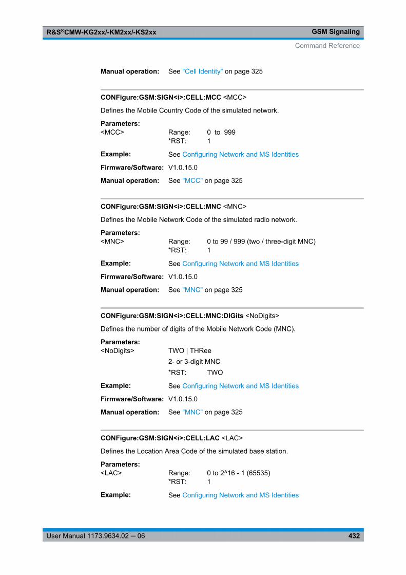
GSM SignalingR&S®CMW-KG2xx/-KM2xx/-KS2xx
432User Manual 1173.9634.02 ─ 06
Manual operation: See "Cell Identity" on page 325
CONFigure:GSM:SIGN<i>:CELL:MCC <MCC>
Defines the Mobile Country Code of the simulated network.
Parameters:<MCC> Range: 0 to 999
*RST: 1
Example: See Configuring Network and MS Identities
Firmware/Software: V1.0.15.0
Manual operation: See "MCC" on page 325
CONFigure:GSM:SIGN<i>:CELL:MNC <MNC>
Defines the Mobile Network Code of the simulated radio network.
Parameters:<MNC> Range: 0 to 99 / 999 (two / three-digit MNC)
*RST: 1
Example: See Configuring Network and MS Identities
Firmware/Software: V1.0.15.0
Manual operation: See "MNC" on page 325
CONFigure:GSM:SIGN<i>:CELL:MNC:DIGits <NoDigits>
Defines the number of digits of the Mobile Network Code (MNC).
Parameters:<NoDigits> TWO | THRee
2- or 3-digit MNC*RST: TWO
Example: See Configuring Network and MS Identities
Firmware/Software: V1.0.15.0
Manual operation: See "MNC" on page 325
CONFigure:GSM:SIGN<i>:CELL:LAC <LAC>
Defines the Location Area Code of the simulated base station.
Parameters:<LAC> Range: 0 to 2^16 - 1 (65535)
*RST: 1
Example: See Configuring Network and MS Identities
Command Reference
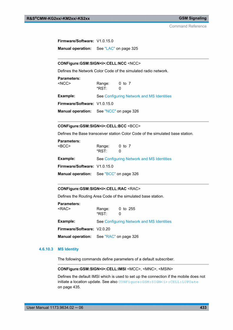
GSM SignalingR&S®CMW-KG2xx/-KM2xx/-KS2xx
433User Manual 1173.9634.02 ─ 06
Firmware/Software: V1.0.15.0
Manual operation: See "LAC" on page 325
CONFigure:GSM:SIGN<i>:CELL:NCC <NCC>
Defines the Network Color Code of the simulated radio network.
Parameters:<NCC> Range: 0 to 7
*RST: 0
Example: See Configuring Network and MS Identities
Firmware/Software: V1.0.15.0
Manual operation: See "NCC" on page 326
CONFigure:GSM:SIGN<i>:CELL:BCC <BCC>
Defines the Base transceiver station Color Code of the simulated base station.
Parameters:<BCC> Range: 0 to 7
*RST: 0
Example: See Configuring Network and MS Identities
Firmware/Software: V1.0.15.0
Manual operation: See "BCC" on page 326
CONFigure:GSM:SIGN<i>:CELL:RAC <RAC>
Defines the Routing Area Code of the simulated base station.
Parameters:<RAC> Range: 0 to 255
*RST: 0
Example: See Configuring Network and MS Identities
Firmware/Software: V2.0.20
Manual operation: See "RAC" on page 326
4.6.10.3 MS Identity
The following commands define parameters of a default subscriber.
CONFigure:GSM:SIGN<i>:CELL:IMSI <MCC>, <MNC>, <MSIN>
Defines the default IMSI which is used to set up the connection if the mobile does notinitiate a location update. See also CONFigure: GSM: SIGN<i>: CELL: LUPDate on page 435.
Command Reference
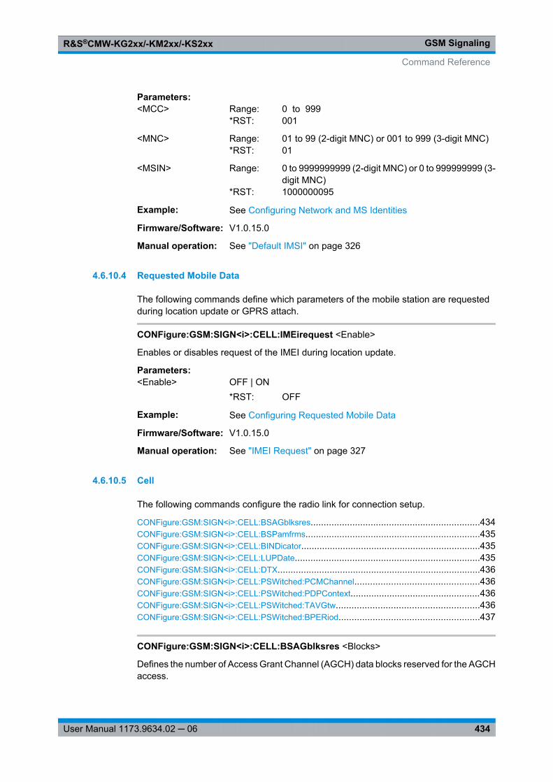
GSM SignalingR&S®CMW-KG2xx/-KM2xx/-KS2xx
434User Manual 1173.9634.02 ─ 06
Parameters:<MCC> Range: 0 to 999
*RST: 001
<MNC> Range: 01 to 99 (2-digit MNC) or 001 to 999 (3-digit MNC)*RST: 01
<MSIN> Range: 0 to 9999999999 (2-digit MNC) or 0 to 999999999 (3-digit MNC)
*RST: 1000000095
Example: See Configuring Network and MS Identities
Firmware/Software: V1.0.15.0
Manual operation: See "Default IMSI" on page 326
4.6.10.4 Requested Mobile Data
The following commands define which parameters of the mobile station are requestedduring location update or GPRS attach.
CONFigure:GSM:SIGN<i>:CELL:IMEirequest <Enable>
Enables or disables request of the IMEI during location update.
Parameters:<Enable> OFF | ON
*RST: OFF
Example: See Configuring Requested Mobile Data
Firmware/Software: V1.0.15.0
Manual operation: See "IMEI Request" on page 327
4.6.10.5 Cell
The following commands configure the radio link for connection setup.
CONFigure: GSM:SIGN<i>:CELL: BSAGblksres .................................................................434CONFigure: GSM:SIGN<i>:CELL: BSPamfrms...................................................................435CONFigure: GSM:SIGN<i>:CELL: BINDicator .....................................................................435CONFigure: GSM:SIGN<i>:CELL: LUPDate .......................................................................435CONFigure: GSM:SIGN<i>:CELL: DTX..............................................................................436CONFigure: GSM:SIGN<i>:CELL: PSWitched: PCMChannel ................................................436CONFigure: GSM:SIGN<i>:CELL: PSWitched: PDPContext ..................................................436CONFigure: GSM:SIGN<i>:CELL: PSWitched: TAVGtw.......................................................436CONFigure: GSM:SIGN<i>:CELL: PSWitched: BPERiod ......................................................437
CONFigure:GSM:SIGN<i>:CELL:BSAGblksres <Blocks>
Defines the number of Access Grant Channel (AGCH) data blocks reserved for the AGCHaccess.
Command Reference
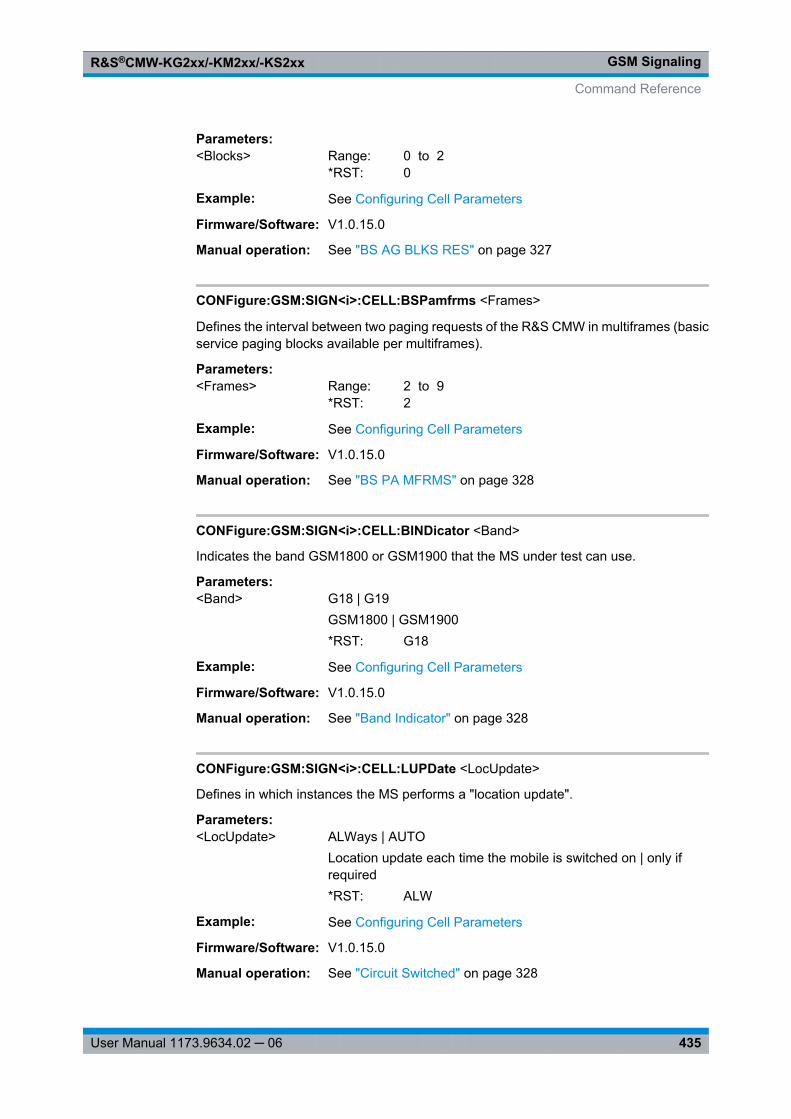
GSM SignalingR&S®CMW-KG2xx/-KM2xx/-KS2xx
435User Manual 1173.9634.02 ─ 06
Parameters:<Blocks> Range: 0 to 2
*RST: 0
Example: See Configuring Cell Parameters
Firmware/Software: V1.0.15.0
Manual operation: See "BS AG BLKS RES" on page 327
CONFigure:GSM:SIGN<i>:CELL:BSPamfrms <Frames>
Defines the interval between two paging requests of the R&S CMW in multiframes (basicservice paging blocks available per multiframes).
Parameters:<Frames> Range: 2 to 9
*RST: 2
Example: See Configuring Cell Parameters
Firmware/Software: V1.0.15.0
Manual operation: See "BS PA MFRMS" on page 328
CONFigure:GSM:SIGN<i>:CELL:BINDicator <Band>
Indicates the band GSM1800 or GSM1900 that the MS under test can use.
Parameters:<Band> G18 | G19
GSM1800 | GSM1900*RST: G18
Example: See Configuring Cell Parameters
Firmware/Software: V1.0.15.0
Manual operation: See "Band Indicator" on page 328
CONFigure:GSM:SIGN<i>:CELL:LUPDate <LocUpdate>
Defines in which instances the MS performs a "location update".
Parameters:<LocUpdate> ALWays | AUTO
Location update each time the mobile is switched on | only ifrequired*RST: ALW
Example: See Configuring Cell Parameters
Firmware/Software: V1.0.15.0
Manual operation: See "Circuit Switched" on page 328
Command Reference
GSM SignalingR&S®CMW-KG2xx/-KM2xx/-KS2xx
436User Manual 1173.9634.02 ─ 06
CONFigure:GSM:SIGN<i>:CELL:DTX <Mode>
Specifies whether or not the mobile station may use the operating mode DTX (Discon-tinuous Transmission).
Parameters:<Mode> OFF | ON
Enable | disable DTX mode*RST: OFF
Example: See Configuring Cell Parameters
Firmware/Software: V1.0.15.0
Manual operation: See "Circuit Switched" on page 328
CONFigure:GSM:SIGN<i>:CELL:PSWitched:PCMChannel <Channel>
Selects the channel type that the mobile uses to determine the received signal strengthand quality.
Parameters:<Channel> BCCH | PDCH
*RST: PDCH
Example: See Configuring Cell Parameters
Firmware/Software: V3.0.20
Options: R&S CMW-KS210
Manual operation: See "Packet Switched" on page 328
CONFigure:GSM:SIGN<i>:CELL:PSWitched:PDPContext <Mode>
Defines how the R&S CMW reacts to an ACTIVATE PDP CONTEXT REQUEST sent bythe MS.
Parameters:<Mode> REJect | ACCept
*RST: ACC
Example: See Configuring Cell Parameters
Firmware/Software: V2.0.20
Manual operation: See "Packet Switched" on page 328
CONFigure:GSM:SIGN<i>:CELL:PSWitched:TAVGtw <Value>
Specifies the signal level filter period for power control. The same value is used forTAVG_T and TAVG_W.
Command Reference
GSM SignalingR&S®CMW-KG2xx/-KM2xx/-KS2xx
437User Manual 1173.9634.02 ─ 06
Parameters:<Value> Range: 0 to 25
*RST: 2
Example: See Configuring Cell Parameters
Firmware/Software: V3.0.20
Options: R&S CMW-KS210
Manual operation: See "Packet Switched" on page 328
CONFigure:GSM:SIGN<i>:CELL:PSWitched:BPERiod <Value>
Specifies the BEP_PERIOD defined in 3GPP TS 45.008.
Parameters:<Value> Range: 0 to 10
*RST: 0
Example: See Configuring Cell Parameters
Firmware/Software: V3.0.20
Options: R&S CMW-KS210
Manual operation: See "Packet Switched" on page 328
4.6.10.6 Timer and Constants
The following commands control the timing of the connection.
CONFigure: GSM:SIGN<i>:CELL: RTMS ...........................................................................437CONFigure: GSM:SIGN<i>:CELL: RTBS............................................................................438CONFigure: GSM:SIGN<i>:CELL: ATIMeout......................................................................438CONFigure: GSM:SIGN<i>:CELL: PLUPdate ......................................................................438CONFigure: GSM:SIGN<i>:CELL: PRAupdate ....................................................................438
CONFigure:GSM:SIGN<i>:CELL:RTMS <Time>
Defines the time period after which a previously established but interrupted connectionis dropped by the mobile station (Radiolink Timeout MS).
Parameters:<Time> Number of missing SACCH blocks, only multiples of 4 are allowed
(rounded automatically)Range: 4 to 64Increment: 4*RST: 24
Example: See Setting Timers and Constants
Firmware/Software: V1.0.15.0
Manual operation: See "Radiolink Timeout MS" on page 330
Command Reference
GSM SignalingR&S®CMW-KG2xx/-KM2xx/-KS2xx
438User Manual 1173.9634.02 ─ 06
CONFigure:GSM:SIGN<i>:CELL:RTBS <Time>
Defines the time period after which an existing, but interrupted connection is aborted bythe R&S CMW ("Radiolink Timeout BS").
Parameters:<Time> Number of missing SACCH blocks
Range: 4 to 64Increment: 1*RST: 24
Example: See Setting Timers and Constants
Firmware/Software: V1.0.15.0
Manual operation: See "Radiolink Timeout BS" on page 330
CONFigure:GSM:SIGN<i>:CELL:ATIMeout <Time>
Defines the maximum time period in seconds during which the phone is ringing in thecase of call to mobile (mobile terminated call). If the call is not answered, the R&S CMWreturns to the Synchronized state.
Parameters:<Time> Range: 1 s to 120 s
*RST: 10 sDefault unit: s
Example: See Setting Timers and Constants
Firmware/Software: V2.0.10
Manual operation: See "Alerting Timeout" on page 330
CONFigure:GSM:SIGN<i>:CELL:PLUPdate <Value>
Defines the value of the timer T3212 of the periodic location updating procedure.
Parameters:<Value> Range: 0 to 255
*RST: 0Default unit: deci-hours
Example: See Setting Timers and Constants
Firmware/Software: V1.0.15.0
Manual operation: See "T3212" on page 330
CONFigure:GSM:SIGN<i>:CELL:PRAupdate <Value>
Defines the value of the timer T3312 of the periodic routing area updating procedure.
Command Reference
GSM SignalingR&S®CMW-KG2xx/-KM2xx/-KS2xx
439User Manual 1173.9634.02 ─ 06
Parameters:<Value> Range: 0 to 31
*RST: 0Default unit: deci-hours
Example: See Setting Timers and Constants
Firmware/Software: V1.0.15.0
Manual operation: See "T3312" on page 330
4.6.10.7 Security Settings
The following commands configure parameters related to the authentication procedureand other security procedures.
CONFigure:GSM:SIGN<i>:CELL:SECurity:AUTHenticat <Enable>
Enables or disables authentication, to be performed during location update or attach.
Parameters:<Enable> OFF | ON
*RST: OFF
Example: See Configuring Security Settings
Firmware/Software: V3.0.20
Manual operation: See "Authentication" on page 331
CONFigure:GSM:SIGN<i>:CELL:SECurity:SKEY <SecretKey>
Defines the secret key Ki as 32-digit hexadecimal number. Leading zeros may be omitted.
Parameters:<SecretKey> Range: #H0 to
#HFFFFFFFFFFFFFFFFFFFFFFFFFFFFFFFF*RST: #H000102030405060708090A0B0C0D0E0F
Example: See Configuring Security Settings
Firmware/Software: V3.0.20
Manual operation: See "KI Value" on page 331
CONFigure:GSM:SIGN<i>:CELL:SECurity:SIMCard <SIMcardType>
Selects the type of the used SIM card.
Parameters:<SIMcardType> C3G | C2G
C3G: 3G USIMC2G: 2G SIM*RST: C3G
Command Reference
GSM SignalingR&S®CMW-KG2xx/-KM2xx/-KS2xx
440User Manual 1173.9634.02 ─ 06
Example: See Configuring Security Settings
Firmware/Software: V3.0.20
Manual operation: See "SIM Card Type" on page 331
4.6.10.8 Time
The commands in this section configure and send date and time information to the MS.
CONFigure: GSM:SIGN<i>:CELL: TIME:TSOurce...............................................................440CONFigure: GSM:SIGN<i>:CELL: TIME:DATE...................................................................440CONFigure: GSM:SIGN<i>:CELL: TIME:TIME....................................................................441CONFigure: GSM:SIGN<i>:CELL: TIME:DSTime ................................................................441CONFigure: GSM:SIGN<i>:CELL: TIME:SNOW..................................................................441
CONFigure:GSM:SIGN<i>:CELL:TIME:TSOurce <SourceTime>
Selects the date and time source.
The time source DATE is configured via the following commands:● CONFigure: GSM: SIGN<i>: CELL: TIME: DATE ● CONFigure: GSM: SIGN<i>: CELL: TIME: TIME ● CONFigure: GSM: SIGN<i>: CELL: TIME: DSTime
Parameters:<SourceTime> CMWTime | DATE
CMWTime: Windows date and timeDATE: Date and time specified via remote commands*RST: CMWT
Example: See Sending Date and Time Information to the MS
Firmware/Software: V3.0.20
Options: R&S CMW-KS210
Manual operation: See "Time Source" on page 331
CONFigure:GSM:SIGN<i>:CELL:TIME:DATE <Day>, <Month>, <Year>
Specifies the UTC date for the time source DATE (see CONFigure: GSM: SIGN<i>: CELL: TIME: TSOurce on page 440).
Parameters:<Day> Range: 1 to 31
*RST: 11
<Month> Range: 1 to 12*RST: 11
<Year> Range: 2011 to 9999*RST: 2011
Command Reference
GSM SignalingR&S®CMW-KG2xx/-KM2xx/-KS2xx
441User Manual 1173.9634.02 ─ 06
Example: See Sending Date and Time Information to the MS
Firmware/Software: V3.0.20
Options: R&S CMW-KS210
Manual operation: See "Date / Time (UTC)" on page 332
CONFigure:GSM:SIGN<i>:CELL:TIME:TIME <Hour>, <Minute>, <Second>
Specifies the UTC time for the time source DATE (see CONFigure: GSM: SIGN<i>: CELL: TIME: TSOurce on page 440).
Parameters:<Hour> Range: 0 to 23
*RST: 11
<Minute> Range: 0 to 59*RST: 11
<Second> Range: 0 to 59*RST: 0
Example: See Sending Date and Time Information to the MS
Firmware/Software: V3.0.20
Options: R&S CMW-KS210
Manual operation: See "Date / Time (UTC)" on page 332
CONFigure:GSM:SIGN<i>:CELL:TIME:DSTime <Enable>
Specifies a Daylight Saving Time (DST) offset for the time source DATE (see CONFigure: GSM: SIGN<i>: CELL: TIME: TSOurce on page 440).
Parameters:<Enable> P1H | P2H
P1H: +1h offset if DST is ONP2H: +2h offset if DST is ON*RST: OFF (P1H)Additional parameters: OFF | ON (disables | enables DST)
Example: See Sending Date and Time Information to the MS
Firmware/Software: V3.0.20
Options: R&S CMW-KS210
Manual operation: See "Daylight Saving Time" on page 332
CONFigure:GSM:SIGN<i>:CELL:TIME:SNOW
Triggers the transfer of the date and time information to the MS.
Command Reference
GSM SignalingR&S®CMW-KG2xx/-KM2xx/-KS2xx
442User Manual 1173.9634.02 ─ 06
Example: See Sending Date and Time Information to the MS
Usage: Event
Firmware/Software: V3.0.20
Options: R&S CMW-KS210
Manual operation: See "Send Time" on page 332
4.6.11 Connection Settings
The following commands configure settings for circuit switched or packet switched con-nections.
● CS Connections (General Parameters)................................................................442● AMR Configuration................................................................................................446● VAMOS Configuration...........................................................................................453● PS Connections....................................................................................................454
4.6.11.1 CS Connections (General Parameters)
The following commands configure the DL traffic channel (TCH) and other settings forcircuit switched connections.
CONFigure: GSM:SIGN<i>:CONNection: CSWitched: TSLot.................................................442CONFigure: GSM:SIGN<i>:CONNection: CSWitched: TMODe ..............................................443CONFigure: GSM:SIGN<i>:CONNection: CSWitched: HRSubchannel ...................................443CONFigure: GSM:SIGN<i>:CONNection: CSWitched: DSOurce ............................................443CONFigure: GSM:SIGN<i>:CONNection: CSWitched: LOOP................................................444CONFigure: GSM:SIGN<i>:CONNection: CSWitched: LREClose ...........................................444CONFigure: GSM:SIGN<i>:CONNection: CSWitched: CID ....................................................445CONFigure: GSM:SIGN<i>:CONNection: CSWitched: TCHassign .........................................445CONFigure: GSM:SIGN<i>:CONNection: CSWitched: RFACch .............................................445CONFigure: GSM:SIGN<i>:CONNection: CSWitched: RSACch .............................................445
CONFigure:GSM:SIGN<i>:CONNection:CSWitched:TSLot <Slot>
Selects a traffic channel timeslot for the circuit switched connection.
Parameters:<Slot> Range: 1 to 7
*RST: 3
Example: See Configuring General CS Connection Settings
Firmware/Software: V1.0.15.0V2.0.10: range extended (1 and 7 added)
Manual operation: See "Timeslot" on page 333
Command Reference
GSM SignalingR&S®CMW-KG2xx/-KM2xx/-KS2xx
443User Manual 1173.9634.02 ─ 06
CONFigure:GSM:SIGN<i>:CONNection:CSWitched:TMODe <Mode>
Selects the speech channel coding for circuit switched connections.
Parameters:<Mode> FV1 | FV2 | HV1 | ANFG | ANHG | ANH8 | AWFG | AWF8 |
AWH8FV1: full-rate version 1 speech codecFV2: full-rate version 2 speech codecHV1: half-rate version 1 speech codecANFG: AMR narrowband full-rate GMSK codecANHG: AMR narrowband half-rate GMSK codecANH8: AMR narrowband half-rate 8PSK codecAWFG: AMR wideband full-rate GMSK codecAWF8: AMR wideband full-rate 8PSK codecAWH8: AMR wideband half-rate 8PSK codec*RST: FV1
Example: See Configuring General CS Connection Settings
Firmware/Software: V1.0.15.0V2.0.10: added values FV2, HV1, ANFG, ANHGV2.1.25 added value AWFGV2.1.60: added values ANH8, AWF8, AWH8
Options: R&S CMW-KS210 for all modes except FV1
Manual operation: See "Traffic Mode" on page 333
CONFigure:GSM:SIGN<i>:CONNection:CSWitched:HRSubchannel <Channel>
Selects the subchannel to be used for half-rate coding.
Parameters:<Channel> Range: 0 to 1
*RST: 0
Example: See Configuring General CS Connection Settings
Firmware/Software: V2.1.60
Options: R&S CMW-KS210
Manual operation: See "HR Subchannel" on page 334
CONFigure:GSM:SIGN<i>:CONNection:CSWitched:DSOurce <Mode>
Selects the data which the R&S CMW transmits on its CS DL traffic channel.
ECHO is incompatible with an enabled test loop (see CONFigure: GSM: SIGN<i>: CONNection: CSWitched: LOOP ).
Command Reference
GSM SignalingR&S®CMW-KG2xx/-KM2xx/-KS2xx
444User Manual 1173.9634.02 ─ 06
Parameters:<Mode> ECHO | PR9 | PR11 | PR15 | PR16
ECHO: loop-back of UL speech data after a fixed delayPR9: PRBS 2E9-1PR11: PRBS 2E11-1PR15: PRBS 2E15-1PR16: PRBS 2E16-1*RST: ECHO
Example: See Configuring General CS Connection Settings
Firmware/Software: V2.1.60
Manual operation: See "Data Source" on page 334
CONFigure:GSM:SIGN<i>:CONNection:CSWitched:LOOP <Loop>
Selects a test loop type and activates/deactivates the test loop (i.e. whether the MS iscommanded to establish the test loop).
Parameters:<Loop> A | B | C | I
A: TCH loop including signaling of erased framesB: TCH loop without signaling of erased framesC: TCH burst-by-burst loopI: TCH loop for inband signaling*RST: C, OFFAdditional parameters: OFF | ON (disables | enables the loop)
Example: See Configuring General CS Connection Settings
Firmware/Software: V1.0.15.0V2.0.10: added values A, BV3.0.20: added value I
Options: R&S CMW-KS210 for all loop types except C
Manual operation: See "Loop" on page 334
CONFigure:GSM:SIGN<i>:CONNection:CSWitched:LREClose <RecloseLoop>
Enables or disables automatic re-establishing a test loop after TCH reconfiguration. Re-establishing the test loop is required for MS that open an established test loop when aTCH reconfiguration is performed.
Parameters:<RecloseLoop> OFF | ON
*RST: OFF
Example: See Configuring General CS Connection Settings
Firmware/Software: V2.0.10
Manual operation: See "Loop" on page 334
Command Reference
GSM SignalingR&S®CMW-KG2xx/-KM2xx/-KS2xx
445User Manual 1173.9634.02 ─ 06
CONFigure:GSM:SIGN<i>:CONNection:CSWitched:CID <ID>
Defines a 1 to 20-digit ID number for SMS and circuit switched calls, to be displayed atthe mobile under test. Values are entered as number digits according to table 4-3.
Parameters:<ID> Range: '0' to 'cccccccccccccccccccc' (string)
*RST: '12345'
Example: See Configuring General CS Connection Settings
Firmware/Software: V1.0.15.0
Manual operation: See "Caller ID" on page 335
CONFigure:GSM:SIGN<i>:CONNection:CSWitched:TCHassign <TCHassignment>
Specifies at which time during call/connection setup the traffic channel is assigned.
Parameters:<TCHassignment> VEARly | EARLy | LATE
VEARly: The TCH is assigned very early. Signaling is done viathe Fast Associated Control Channel (FACCH).EARLy: The TCH is assigned early, which means that alertingtakes place on the TCH. For call setup to the traffic channel sig-naling is done via the Standalone Dedicated Control Channel(SDCCH).LATE: The traffic channel is assigned late, which means afteralerting. For call setup to the traffic channel and alerting signalingis done via the SDCCH.*RST: VEAR
Example: See Configuring General CS Connection Settings
Firmware/Software: V2.0.10
Manual operation: See "TCH Assignment" on page 336
CONFigure:GSM:SIGN<i>:CONNection:CSWitched:RFACch <Enable>CONFigure:GSM:SIGN<i>:CONNection:CSWitched:RSACch <Enable>
Enables/disables repeated FACCH and repeated SACCH transmission in the DL GSMsignal.
Parameters:<Enable> OFF | ON
*RST: OFF
Example: See Measuring in FER FACCH and FER SACCH Mode
Firmware/Software: V2.1.25
Options: R&S CMW-KS210
Manual operation: See "Repeated SACCH" on page 336
Command Reference
GSM SignalingR&S®CMW-KG2xx/-KM2xx/-KS2xx
446User Manual 1173.9634.02 ─ 06
4.6.11.2 AMR Configuration
The following commands configure the Adaptive Multi-Rate (AMR) codec for speechchannel coding of circuit switched voice connections.
CONFigure: GSM:SIGN<i>:CONNection: CSWitched: AMR:RSET:NB:FRATe:GMSK.............446CONFigure: GSM:SIGN<i>:CONNection: CSWitched: AMR:RSET:NB:HRATe: GMSK.............447CONFigure: GSM:SIGN<i>:CONNection: CSWitched: AMR:RSET:NB:HRATe: EPSK..............447CONFigure: GSM:SIGN<i>:CONNection: CSWitched: AMR:RSET:WB:FRATe:GMSK.............448CONFigure: GSM:SIGN<i>:CONNection: CSWitched: AMR:RSET:WB:FRATe:EPSK..............448CONFigure: GSM:SIGN<i>:CONNection: CSWitched: AMR:RSET:WB:HRATe: EPSK.............449CONFigure: GSM:SIGN<i>:CONNection: CSWitched: AMR:CMODe: NB:FRATe:GMSK:DL .....449CONFigure: GSM:SIGN<i>:CONNection: CSWitched: AMR:CMODe: NB:FRATe:GMSK:UL .....449CONFigure: GSM:SIGN<i>:CONNection: CSWitched: AMR:CMODe: NB:HRATe: GMSK:DL .....450CONFigure: GSM:SIGN<i>:CONNection: CSWitched: AMR:CMODe: NB:HRATe: GMSK:UL .....450CONFigure: GSM:SIGN<i>:CONNection: CSWitched: AMR:CMODe: NB:HRATe: EPSK:DL ......450CONFigure: GSM:SIGN<i>:CONNection: CSWitched: AMR:CMODe: NB:HRATe: EPSK:UL ......450CONFigure: GSM:SIGN<i>:CONNection: CSWitched: AMR:CMODe: WB:FRATe:GMSK:
DL ......................................................................................................................451CONFigure: GSM:SIGN<i>:CONNection: CSWitched: AMR:CMODe: WB:FRATe:GMSK:
UL ......................................................................................................................451CONFigure: GSM:SIGN<i>:CONNection: CSWitched: AMR:CMODe: WB:FRATe:EPSK:DL ......451CONFigure: GSM:SIGN<i>:CONNection: CSWitched: AMR:CMODe: WB:FRATe:EPSK:UL ......451CONFigure: GSM:SIGN<i>:CONNection: CSWitched: AMR:CMODe: WB:HRATe: EPSK:DL .....451CONFigure: GSM:SIGN<i>:CONNection: CSWitched: AMR:CMODe: WB:HRATe: EPSK:UL .....451SENSe: GSM:SIGN<i>:MSSinfo: AMR:CMODe: NB:HRATe: EPSK:DL? .................................452SENSe: GSM:SIGN<i>:MSSinfo: AMR:CMODe: NB:HRATe: EPSK:UL? .................................452SENSe: GSM:SIGN<i>:MSSinfo: AMR:CMODe: WB:FRATe:EPSK:DL? .................................452SENSe: GSM:SIGN<i>:MSSinfo: AMR:CMODe: WB:FRATe:EPSK:UL? .................................452SENSe: GSM:SIGN<i>:MSSinfo: AMR:CMODe: WB:HRATe: EPSK:DL? ................................452SENSe: GSM:SIGN<i>:MSSinfo: AMR:CMODe: WB:HRATe: EPSK:UL? ................................452SENSe: GSM:SIGN<i>:MSSinfo: AMR:CMODe: NB:FRATe:GMSK:DL? ................................452SENSe: GSM:SIGN<i>:MSSinfo: AMR:CMODe: NB:FRATe:GMSK:UL? ................................452SENSe: GSM:SIGN<i>:MSSinfo: AMR:CMODe: NB:HRATe: GMSK:DL? ................................452SENSe: GSM:SIGN<i>:MSSinfo: AMR:CMODe: NB:HRATe: GMSK:UL? ................................452SENSe: GSM:SIGN<i>:MSSinfo: AMR:CMODe: WB:FRATe:GMSK:DL? ................................452SENSe: GSM:SIGN<i>:MSSinfo: AMR:CMODe: WB:FRATe:GMSK:UL? ................................452
CONFigure:GSM:SIGN<i>:CONNection:CSWitched:AMR:RSET:NB:FRATe:GMSK<CodecMode>(4)
Configures up to four supported modes for the full-rate narrowband AMR codec (GMSKmodulation), i.e. assigns data rates to the modes.
The four data rates must be different from each other. They are automatically sorted indescending order so that Rate (Mode 4) > Rate (Mode 3) > Rate (Mode 2) > Rate (Mode1). You can deactivate modes (OFF) to restrict the test model to less than 4 supportedmodes.
Command Reference
GSM SignalingR&S®CMW-KG2xx/-KM2xx/-KS2xx
447User Manual 1173.9634.02 ─ 06
Parameters:<CodecMode> C0475 | C0515 | C0590 | C0670 | C0740 | C0795 | C1020 |
C1220Comma separated list of 4 values: data rates for mode 4 to 1C0475 to C1220: 4.75 kBit/s to 12.2 kBit/sAdditional parameters: OFF | ON (disables | enables the mode)*RST: C1220, C0795, C0590, C0475
Example: See Configuring AMR Settings
Firmware/Software: V2.0.10
Options: R&S CMW-KS210
Manual operation: See "Rate Set" on page 338
CONFigure:GSM:SIGN<i>:CONNection:CSWitched:AMR:RSET:NB:HRATe:GMSK<CodecMode>(4)
Configures up to four supported modes for the half-rate narrowband AMR codec (GMSKmodulation), i.e. assigns data rates to the modes.
The selected data rates must be different. They are automatically sorted so that Rate(Mode 4) > Rate (Mode 3) > Rate (Mode 2) > Rate (Mode 1). You can deactivate modes(OFF) to restrict the test model to less than 4 supported modes.
Parameters:<CodecMode> C0475 | C0515 | C0590 | C0670 | C0740 | C0795
Comma separated list of 4 values: data rates for mode 4 to 1C0475 to C0795: 4.75 kBit/s to 7.95 kBit/sAdditional parameters: OFF | ON (disables | enables the mode)*RST: C0795, C0670, C0590, C0515
Example: See Configuring AMR Settings
Firmware/Software: V2.0.10
Options: R&S CMW-KS210
CONFigure:GSM:SIGN<i>:CONNection:CSWitched:AMR:RSET:NB:HRATe:EPSK<CodecMode>(4)
Configures up to four supported modes for the half-rate narrowband AMR codec (8PSKmodulation), i.e. assigns data rates to the modes.
The four data rates must be different from each other. They are automatically sorted indescending order so that Rate (Mode 4) > Rate (Mode 3) > Rate (Mode 2) > Rate (Mode1). You can deactivate modes (OFF) to restrict the test model to less than 4 supportedmodes.
Command Reference
GSM SignalingR&S®CMW-KG2xx/-KM2xx/-KS2xx
448User Manual 1173.9634.02 ─ 06
Parameters:<CodecMode> C0475 | C0515 | C0590 | C0670 | C0740 | C0795 | C1020 |
C1220Comma separated list of 4 values: data rates for mode 4 to 1C0475 to C1220: 4.75 kBit/s to 12.2 kBit/sAdditional parameters: OFF | ON (disables | enables the mode)*RST: C1220, C0795, C0590, C0475
Example: See Configuring AMR Settings
Firmware/Software: V2.1.60
Options: R&S CMW-KS210
CONFigure:GSM:SIGN<i>:CONNection:CSWitched:AMR:RSET:WB:FRATe:GMSK<CodecMode>(3)
Configures up to three supported modes for the half-rate narrowband AMR codec (GMSKmodulation), i.e. assigns data rates to the modes.
The selected data rates must be different. They are automatically sorted so that Rate(Mode 3) > Rate (Mode 2) > Rate (Mode 1). You can deactivate modes (OFF) to restrictthe test model to less than 3 supported modes.
Parameters:<CodecMode> C0660 | C0885 | C1265
Comma separated list of 3 values: data rates for mode 3 to 1C0660 to C1265: 6.60 kBit/s to 12.65 kBit/sAdditional parameters: OFF | ON (disables | enables the mode)*RST: C1265, C0885, C0660
Example: See Configuring AMR Settings
Firmware/Software: V2.1.25
Options: R&S CMW-KS210
CONFigure:GSM:SIGN<i>:CONNection:CSWitched:AMR:RSET:WB:FRATe:EPSK<CodecMode>(4)
Configures up to four supported modes for the full-rate wideband AMR codec (8PSKmodulation), i.e. assigns data rates to the modes.
The four data rates must be different from each other. They are automatically sorted indescending order so that Rate (Mode 4) > Rate (Mode 3) > Rate (Mode 2) > Rate (Mode1). You can deactivate modes (OFF) to restrict the test model to less than 4 supportedmodes.
Command Reference
GSM SignalingR&S®CMW-KG2xx/-KM2xx/-KS2xx
449User Manual 1173.9634.02 ─ 06
Parameters:<CodecMode> C0660 | C0885 | C1265 | C1585 | C2385
Comma separated list of 4 values: data rates for mode 4 to 1C0660 to C2385: 6.6 kBit/s to 23.85 kBit/sAdditional parameters: OFF | ON (disables | enables the mode)*RST: C2385, C1585, C1265, C0660
Example: See Configuring AMR Settings
Firmware/Software: V2.1.60
Options: R&S CMW-KS210
CONFigure:GSM:SIGN<i>:CONNection:CSWitched:AMR:RSET:WB:HRATe:EPSK<CodecMode>(3)
Configures up to three supported modes for the half-rate wideband AMR codec (8PSKmodulation), i.e. assigns data rates to the modes.
The three data rates must be different from each other. They are automatically sorted indescending order so that Rate (Mode 3) > Rate (Mode 2) > Rate (Mode 1). You candeactivate modes (OFF) to restrict the test model to less than 3 supported modes.
Parameters:<CodecMode> C0660 | C0885 | C1265
Comma separated list of 3 values: data rates for mode 3 to 1C0660 to C1265: 6.6 kBit/s to 12.65 kBit/sAdditional parameters: OFF | ON (disables | enables the mode)*RST: C1265, C0885, C0660
Example: See Configuring AMR Settings
Firmware/Software: V2.1.60
Options: R&S CMW-KS210
CONFigure:GSM:SIGN<i>:CONNection:CSWitched:AMR:CMODe:NB:FRATe:GMSK:DL <CodecMode>
CONFigure:GSM:SIGN<i>:CONNection:CSWitched:AMR:CMODe:NB:FRATe:GMSK:UL <CodecMode>
Select the codec modes to be used by the R&S CMW (downlink) and the MS (uplink) forthe full-rate narrowband AMR codec (GMSK modulation).
Only active codec modes can be selected. For configuration and activation/deactivationof the codec modes see CONFigure: GSM: SIGN<i>: CONNection: CSWitched: AMR: RSET: NB: FRATe: GMSK on page 446.
Parameters:<CodecMode> Range: 1 to 4 (if all codec modes are active, otherwise less)
*RST: 3
Example: See Configuring AMR Settings
Command Reference
GSM SignalingR&S®CMW-KG2xx/-KM2xx/-KS2xx
450User Manual 1173.9634.02 ─ 06
Firmware/Software: V2.0.10
Options: R&S CMW-KS210
Manual operation: See "Codec Mode Downlink / Uplink" on page 337
CONFigure:GSM:SIGN<i>:CONNection:CSWitched:AMR:CMODe:NB:HRATe:GMSK:DL <CodecMode>
CONFigure:GSM:SIGN<i>:CONNection:CSWitched:AMR:CMODe:NB:HRATe:GMSK:UL <CodecMode>
Select the codec modes to be used by the R&S CMW (downlink) and the MS (uplink) forthe half-rate narrowband AMR codec (GMSK modulation).
Only active codec modes can be selected. For configuration and activation/deactivationof the codec modes see CONFigure: GSM: SIGN<i>: CONNection: CSWitched: AMR: RSET: NB: HRATe: GMSK on page 447.
Parameters:<CodecMode> Range: 1 to 4 (if all codec modes are active, otherwise less)
*RST: 3
Example: See Configuring AMR Settings
Firmware/Software: V2.0.10
Options: R&S CMW-KS210
CONFigure:GSM:SIGN<i>:CONNection:CSWitched:AMR:CMODe:NB:HRATe:EPSK:DL <CodecMode>
CONFigure:GSM:SIGN<i>:CONNection:CSWitched:AMR:CMODe:NB:HRATe:EPSK:UL <CodecMode>
Select the codec modes to be used by the R&S CMW (downlink) and the MS (uplink) forthe half-rate narrowband AMR codec (8PSK modulation).
Only active codec modes can be selected. For configuration and activation/deactivationof the codec modes see CONFigure: GSM: SIGN<i>: CONNection: CSWitched: AMR: RSET: NB: HRATe: EPSK on page 447.
Parameters:<CodecMode> Range: 1 to 4 (if all codec modes are active, otherwise less)
*RST: 3
Example: See Configuring AMR Settings
Firmware/Software: V2.1.60
Options: R&S CMW-KS210
Command Reference
GSM SignalingR&S®CMW-KG2xx/-KM2xx/-KS2xx
451User Manual 1173.9634.02 ─ 06
CONFigure:GSM:SIGN<i>:CONNection:CSWitched:AMR:CMODe:WB:FRATe:GMSK:DL <CodecMode>
CONFigure:GSM:SIGN<i>:CONNection:CSWitched:AMR:CMODe:WB:FRATe:GMSK:UL <CodecMode>
Select the codec modes to be used by the R&S CMW (downlink) and the MS (uplink) forthe full-rate wideband AMR codec (GMSK modulation).
Only active codec modes can be selected. For configuration and activation/deactivationof the codec modes see CONFigure: GSM: SIGN<i>: CONNection: CSWitched: AMR: RSET: WB: FRATe: GMSK .
Parameters:<CodecMode> Range: 1 to 3 (if all codec modes are active, otherwise less)
*RST: 3
Example: See Configuring AMR Settings
Firmware/Software: V2.1.25
Options: R&S CMW-KS210
CONFigure:GSM:SIGN<i>:CONNection:CSWitched:AMR:CMODe:WB:FRATe:EPSK:DL <CodecMode>
CONFigure:GSM:SIGN<i>:CONNection:CSWitched:AMR:CMODe:WB:FRATe:EPSK:UL <CodecMode>
Select the codec modes to be used by the R&S CMW (downlink) and the MS (uplink) forthe full-rate wideband AMR codec (8PSK modulation).
Only active codec modes can be selected. For configuration and activation/deactivationof the codec modes see CONFigure: GSM: SIGN<i>: CONNection: CSWitched: AMR: RSET: WB: FRATe: EPSK on page 448.
Parameters:<CodecMode> Range: 1 to 4 (if all codec modes are active, otherwise less)
*RST: 3
Example: See Configuring AMR Settings
Firmware/Software: V2.1.60
Options: R&S CMW-KS210
CONFigure:GSM:SIGN<i>:CONNection:CSWitched:AMR:CMODe:WB:HRATe:EPSK:DL <CodecMode>
CONFigure:GSM:SIGN<i>:CONNection:CSWitched:AMR:CMODe:WB:HRATe:EPSK:UL <CodecMode>
Select the codec modes to be used by the R&S CMW (downlink) and the MS (uplink) forthe half-rate wideband AMR codec (8PSK modulation).
Command Reference
GSM SignalingR&S®CMW-KG2xx/-KM2xx/-KS2xx
452User Manual 1173.9634.02 ─ 06
Only active codec modes can be selected. For configuration and activation/deactivationof the codec modes see CONFigure: GSM: SIGN<i>: CONNection: CSWitched: AMR: RSET: WB: HRATe: EPSK on page 449.
Parameters:<CodecMode> Range: 1 to 3 (if all codec modes are active, otherwise less)
*RST: 3
Example: See Configuring AMR Settings
Firmware/Software: V2.1.60
Options: R&S CMW-KS210
SENSe:GSM:SIGN<i>:MSSinfo:AMR:CMODe:NB:HRATe:EPSK:DL?SENSe:GSM:SIGN<i>:MSSinfo:AMR:CMODe:NB:HRATe:EPSK:UL?SENSe:GSM:SIGN<i>:MSSinfo:AMR:CMODe:WB:FRATe:EPSK:DL?SENSe:GSM:SIGN<i>:MSSinfo:AMR:CMODe:WB:FRATe:EPSK:UL?SENSe:GSM:SIGN<i>:MSSinfo:AMR:CMODe:WB:HRATe:EPSK:DL?SENSe:GSM:SIGN<i>:MSSinfo:AMR:CMODe:WB:HRATe:EPSK:UL?SENSe:GSM:SIGN<i>:MSSinfo:AMR:CMODe:NB:FRATe:GMSK:DL?SENSe:GSM:SIGN<i>:MSSinfo:AMR:CMODe:NB:FRATe:GMSK:UL?SENSe:GSM:SIGN<i>:MSSinfo:AMR:CMODe:NB:HRATe:GMSK:DL?SENSe:GSM:SIGN<i>:MSSinfo:AMR:CMODe:NB:HRATe:GMSK:UL?SENSe:GSM:SIGN<i>:MSSinfo:AMR:CMODe:WB:FRATe:GMSK:DL?SENSe:GSM:SIGN<i>:MSSinfo:AMR:CMODe:WB:FRATe:GMSK:UL?Query the DL AMR codec mode requested by the MS (:DL) and the actual UL codecmode used by the MS (:UL). Separate commands are available for the half-rate (HRATe)and full-rate (FRATe) narrowband (NB) and wideband (WB) AMR codecs, for GMSK and8PSK modulation.
For the modes really used in downlink and requested for uplink, refer to theCONFigure:GSM:SIGN<i>:CONNection:CSWitched:AMR:CMODe:... com-mands.
Return values: <CodecMode> Range: 1 to 4 (1 to 3 for WB:FRATe:GMSK and
WB:HRATe:EPSK)
Example: See Configuring AMR Settings
Usage: Query only
Firmware/Software: V2.0.10V2.1.25: AMR-WB codec commands addedV2.1.60: EPSK commands added
Options: R&S CMW-KS210
Command Reference
GSM SignalingR&S®CMW-KG2xx/-KM2xx/-KS2xx
453User Manual 1173.9634.02 ─ 06
4.6.11.3 VAMOS Configuration
The following commands configure Voice services over Adaptive Multi-user Channels onOne Slot (VAMOS) for circuit switched connections.
CONFigure: GSM:SIGN<i>:CONNection: CSWitched: VAMos:ENABle ...................................453CONFigure: GSM:SIGN<i>:CONNection: CSWitched: VAMos:MSLevel .................................453CONFigure: GSM:SIGN<i>:CONNection: CSWitched: VAMos ...............................................453
CONFigure:GSM:SIGN<i>:CONNection:CSWitched:VAMos:ENABle <Enable>
Activates or deactivates Voice services over Adaptive Multi-user Channels on One Slot(VAMOS).
Parameters:<Enable> OFF | ON
*RST: OFF
Example: See Configuring VAMOS Support
Firmware/Software: V2.0.10
Options: R&S CMW-KS203
Manual operation: See "VAMOS > Enable" on page 339
CONFigure:GSM:SIGN<i>:CONNection:CSWitched:VAMos:MSLevel <Mode>
Selects the VAMOS support level of the mobile.
Parameters:<Mode> VAM1 | VAM2
VAMOS support levels I or II*RST: VAM1
Example: See Configuring VAMOS Support
Firmware/Software: V2.0.20
Options: R&S CMW-KS203
Manual operation: See "VAMOS > Mobile Support Level" on page 339
CONFigure:GSM:SIGN<i>:CONNection:CSWitched:VAMos <Subchannel>,<TSCactiveSubch>, <TSCsetActSubch>, <TSCotherSubch>,<TSCsetOthSubch>, <SubchPowImbRat>, <Proflie>
Configures VAMOS. For background information see chapter 4.2.12.4, "VAMOS",on page 284.
Parameters:<Subchannel> VAMOS subchannel to be used for the DUT (active subchannel)
Range: 0 to 1*RST: 0
Command Reference
GSM SignalingR&S®CMW-KG2xx/-KM2xx/-KS2xx
454User Manual 1173.9634.02 ─ 06
<TSCactiveSubch> TSC to be used for the DUT (active subchannel)Range: 0 to 7*RST: 0
<TSCsetActSubch> TSC set to be used for the DUT (active subchannel)Range: 1 to 2*RST: 1
<TSCotherSubch> TSC to be used for the virtual second VAMOS user (other sub-channel)Range: 0 to 7*RST: 0
<TSCsetOthSubch> TSC set to be used for the virtual second VAMOS user (othersubchannel)Range: 1 to 2*RST: 2
<SubchPowImbRat> Subchannel power imbalance ratio, i.e. power of VAMOS sub-channel 0 relative to VAMOS subchannel 1Range: -15 dB to 15 dB*RST: 0 dBDefault unit: dB
<Proflie> SUSer | TUSer | TUDTxVAMOS profile, determines that the DL signal is generated for:SUSer: Single VAMOS user. There is no second VAMOS user (noteven in DTX mode).TUSer: Two active VAMOS users. The downlink signal containsspeech frames and signaling data for both users.TUDTx: Two VAMOS users, DUT active, second user in DTXmode. The downlink signal contains speech frames for the DUTonly. For the virtual user DTX is transmitted.*RST: TUS
Example: See Configuring VAMOS Support
Firmware/Software: V2.0.10
Options: R&S CMW-KS203
Manual operation: See "VAMOS > Active Subchannel" on page 339
4.6.11.4 PS Connections
The following commands configure settings for packet switched connections. For addi-tional settings see also chapter 4.6.6, "Slot Configuration and Resulting Throughput",on page 399.
CONFigure: GSM:SIGN<i>:CONNection: PSWitched: SERVice ............................................455CONFigure: GSM:SIGN<i>:CONNection: PSWitched: TLEVel ...............................................455CONFigure: GSM:SIGN<i>:CONNection: PSWitched: CSCHeme: UL .....................................455CONFigure: GSM:SIGN<i>:CONNection: PSWitched: IREDundancy .....................................456
Command Reference

GSM SignalingR&S®CMW-KG2xx/-KM2xx/-KS2xx
455User Manual 1173.9634.02 ─ 06
CONFigure: GSM:SIGN<i>:CONNection: PSWitched: DSOurce ............................................456CONFigure: GSM:SIGN<i>:CONNection: PSWitched: DLDCarrier: ENABle .............................457CONFigure: GSM:SIGN<i>:CONNection: PSWitched: EDALlocation ......................................457CONFigure: GSM:SIGN<i>:CONNection: PSWitched: NOPDus .............................................457CONFigure: GSM:SIGN<i>:CONNection: PSWitched: SOFFset............................................458CONFigure: GSM:SIGN<i>:CONNection: PSWitched: CATYpe .............................................458
CONFigure:GSM:SIGN<i>:CONNection:PSWitched:SERVice <Service>
Selects a service mode for the PS connection.
Parameters:<Service> TMA | TMB | BLER | SRB
TMA: test mode ATMB: test mode BBLER: BLER modeSRB: EGPRS switched radio block loopback mode*RST: BLER
Example: See Configuring PS Connection Settings
Firmware/Software: V2.0.20V2.1.60: SRB added
Manual operation: See "Service Selection" on page 340
CONFigure:GSM:SIGN<i>:CONNection:PSWitched:TLEVel <TBFlevel>
Selects the set of modulation and coding schemes to be used.
Parameters:<TBFlevel> GPRS | EGPRs | EG2A
GPRSCS-1 to CS-4EGPRsMCS-1 to MCS-9EG2ADL: MCS-1 to MCS-4, MCS-7, MCS-8, DAS-5 to DAS-12UL: MCS-1 to MCS-6, UAS-7 to UAS-11*RST: EGPR
Example: See Configuring PS Connection Settings
Firmware/Software: V2.0.20
Options: R&S CMW-KS201 for EG2A
Manual operation: See "TBF Level" on page 306
CONFigure:GSM:SIGN<i>:CONNection:PSWitched:CSCHeme:UL <CScheme>
Selects the coding scheme for uplink packet data channels.
Command Reference
GSM SignalingR&S®CMW-KG2xx/-KM2xx/-KS2xx
456User Manual 1173.9634.02 ─ 06
The selected value must be compatible to the configured set of modulation and codingschemes, see CONFigure: GSM: SIGN<i>: CONNection: PSWitched: TLEVel on page 455.
Parameters:<CScheme> C1 | C2 | C3 | C4 | MC1 | MC2 | MC3 | MC4 | MC5 | MC6 | MC7 |
MC8 | MC9 | UA7 | UA8 | UA9 | UA10 | UA11C1 to C4: CS-1 to CS-4MC1 to MC9: MCS-1 to MCS-9UA7 to UA11: UAS-7 to UAS-11*RST: MC1
Example: See Configuring PS Connection Settings
Firmware/Software: V2.0.20
Options: R&S CMW-KS201 for UAS-i
Manual operation: See "UL Coding Scheme" on page 307
CONFigure:GSM:SIGN<i>:CONNection:PSWitched:IREDundancy <Enable>
Enables or disables the incremental redundancy RLC mode for the downlink.
Parameters:<Enable> OFF | ON
*RST: ON
Example: See Configuring PS Connection Settings
Firmware/Software: V3.0.20
Options: R&S CMW-KS210
Manual operation: See "Incremental Redundancy" on page 341
CONFigure:GSM:SIGN<i>:CONNection:PSWitched:DSOurce <Mode>
Selects the data which the R&S CMW transmits on its DL traffic channel for PS connec-tions.
Parameters:<Mode> PR9 | PR11 | PR15 | PR16
PR9: PRBS 2E9-1PR11: PRBS 2E11-1PR15: PRBS 2E15-1PR16: PRBS 2E16-1*RST: PR9
Example: See Configuring PS Connection Settings
Firmware/Software: V2.0.20
Options: R&S CMW-KS210
Command Reference
GSM SignalingR&S®CMW-KG2xx/-KM2xx/-KS2xx
457User Manual 1173.9634.02 ─ 06
Manual operation: See "Data Source" on page 341
CONFigure:GSM:SIGN<i>:CONNection:PSWitched:DLDCarrier:ENABle <Enable>
Enables or disables the downlink dual carrier mode. In this mode, the R&S CMW usestwo radio frequency channels to assign resources to the mobile station; see 3GPP TS44.060.
Some settings can be configured individually per carrier. The related commands distin-guish the two carriers via the mnemonics CARRier1 and CARRier2. See e.g. CONFigure: GSM: SIGN<i>: RFSettings: CHANnel: TCH[: CARRier<Carrier>] on page 420.
Parameters:<Enable> OFF | ON
*RST: OFF
Example: See Configuring PS Connection Settings
Firmware/Software: V2.0.20
Options: R&S CMW-KS201
Manual operation: See "DL Dual Carrier" on page 341
CONFigure:GSM:SIGN<i>:CONNection:PSWitched:EDALlocation <Mode>
Enables or disables the optional medium access mode "extended dynamic allocation".
Parameters:<Mode> OFF | ON | AUTO
OFF: disabledON: enabledAUTO: enabled if supported by the mobile, otherwise disabled*RST: AUTO
Example: See Configuring PS Connection Settings
Firmware/Software: V3.0.20
Manual operation: See "Extended Dynamic Allocation" on page 342
CONFigure:GSM:SIGN<i>:CONNection:PSWitched:NOPDus <Number>
Number of PDUs that the MS is to transmit in the uplink during GPRS test mode A. Ifsupported by the mobile, a value of 0 can be used to request an "infinite" test mode thatis not terminated by the mobile after a certain number of PDUs.
Parameters:<Number> Range: 0 to 4095
*RST: 4095
Example: See Configuring PS Connection Settings
Command Reference
GSM SignalingR&S®CMW-KG2xx/-KM2xx/-KS2xx
458User Manual 1173.9634.02 ─ 06
Firmware/Software: V2.0.20
Manual operation: See "No of PDUs" on page 342
CONFigure:GSM:SIGN<i>:CONNection:PSWitched:SOFFset <Offset>
Timeslot that is to be taken as the first DL timeslot when the MS is in multislot operation(downlink timeslot offset parameter in the GPRS_TEST_MODE_CMD).
Parameters:<Offset> Range: 0 to 7
*RST: 0
Example: See Configuring PS Connection Settings
Firmware/Software: V2.0.20
Manual operation: See "Slot Offset" on page 342
CONFigure:GSM:SIGN<i>:CONNection:PSWitched:CATYpe <Mode>
Selects the burst type to be used by a mobile for sending a PACKET CONTROLACKNOWLEDGEMENT.
Parameters:<Mode> NBURsts | ABURsts
NBURsts: normal burstsABURsts: access bursts*RST: NBUR
Example: See Configuring PS Connection Settings
Firmware/Software: V2.1.60
Manual operation: See "Control Ack Type" on page 342
4.6.12 Trigger Signal Settings
The following command configures trigger signals provided by the "GSM Signaling"application. For an overview of all supported trigger signals see chapter 4.2.8, "TriggerSignals", on page 262.
CONFigure:GSM:SIGN<i>:TRIGger:FTMode <FrameTriggerMod>
Configures the frame trigger signal.
Command Reference
GSM SignalingR&S®CMW-KG2xx/-KM2xx/-KS2xx
459User Manual 1173.9634.02 ─ 06
Parameters:<FrameTriggerMod> EVERy | EWIDle | M26 | M52 | M104
EVERy: The frame trigger signal is generated for each uplinkframe (single frame trigger).EWIDle: The frame trigger signal is generated for each uplinkframe except for idle frames (single frame trigger).M26 | M52 | M104: The frame trigger signal is generated for each26th, 52nd or 104th uplink frame (multiframe trigger).*RST: EVER
Example: See Configuring Trigger Signals
Firmware/Software: V2.0.10
Manual operation: See "Frame Trigger Mode" on page 343
4.6.13 Messaging (SMS)
The following commands configure parameters of the Short Message Service (SMS) andreturn information about received short messages.
CONFigure: GSM:SIGN<i>:SMS:OUTGoing: INTernal .........................................................459SENSe: GSM:SIGN<i>:SMS:INComing: INFO:MTEXt?........................................................459SENSe: GSM:SIGN<i>:SMS:INComing: INFO:MLENgth? ....................................................460CLEan: GSM:SIGN<i>:SMS:INComing: INFO:MTEXt..........................................................460SENSe: GSM:SIGN<i>:SMS:INFO:LRMessage: RFLag? .....................................................460
CONFigure:GSM:SIGN<i>:SMS:OUTGoing:INTernal <SMSInternal>
Defines the message text for SMS messages to be sent to the MS. It is encoded as 7-bitASCII text.
Parameters:<SMSInternal> String with up to 160 characters
*RST: "R&S Short Message Service Text. The quick brownfox jumps over the lazy dog.THE QUICK BROWNFOX JUMPS OVER THE LAZY DOG.0123456789 !"#\*%+-/()<>?=;@$,"
Example: See Sending / Receiving an SMS
Firmware/Software: V2.0.10
Manual operation: See "Outgoing > Internal > Outgoing SMS" on page 343
SENSe:GSM:SIGN<i>:SMS:INComing:INFO:MTEXt?
Returns the text of the last SMS message received from the MS. Only 7-bit ASCII text issupported.
Return values: <MessageText> Message text as string
Command Reference
GSM SignalingR&S®CMW-KG2xx/-KM2xx/-KS2xx
460User Manual 1173.9634.02 ─ 06
Example: See Sending / Receiving an SMS
Usage: Query only
Firmware/Software: V2.0.10
Manual operation: See "Incoming > Message Text / Message Length" on page 344
SENSe:GSM:SIGN<i>:SMS:INComing:INFO:MLENgth?
Returns the length of the last SMS message received from the MS.
Return values: <MessageLength> Number of characters of the message
Range: 0 to 160
Example: See Sending / Receiving an SMS
Usage: Query only
Firmware/Software: V2.0.10
Manual operation: See "Incoming > Message Text / Message Length" on page 344
CLEan:GSM:SIGN<i>:SMS:INComing:INFO:MTEXt
Resets all parameters related to a received SMS message. The message text and theinformation about the message length are deleted. The "message read" flag is set to true.
Example: See Sending / Receiving an SMS
Usage: Event
Firmware/Software: V2.0.10
Manual operation: See "Incoming > Clear Message Text" on page 344
SENSe:GSM:SIGN<i>:SMS:INFO:LRMessage:RFLag?
Queries the "message read" flag for the last received message.
The flag is true (ON) in the following cases:● No SMS message has been received.● The last received SMS message has been read, see SENSe: GSM: SIGN<i>: SMS:
INComing: INFO: MTEXt? on page 459.
● The last received SMS message has been deleted, see CLEan: GSM: SIGN<i>: SMS: INComing: INFO: MTEXt on page 460.
Return values: <LastRecMessRead> OFF | ON
OFF: unread message availableON: no unread message available*RST: ON
Command Reference
GSM SignalingR&S®CMW-KG2xx/-KM2xx/-KS2xx
461User Manual 1173.9634.02 ─ 06
Example: See Sending / Receiving an SMS
Usage: Query only
Firmware/Software: V2.0.10
Manual operation: See "Incoming > Clear Message Text" on page 344
4.6.14 Measurement Slot Settings
The following command configures the UL measurement slot.
CONFigure:GSM:SIGN<i>:MSLot:UL <Slot>
Specifies the uplink measurement slot, i.e. the slot evaluated by measurements runningin parallel to the "GSM Signaling" application.
Parameters:<Slot> Range: 0 to 7
*RST: 3
Example: See Configuring General CS Connection Settings
Firmware/Software: V2.0.10
Manual operation: See "Measurement Slot UL" on page 344
4.6.15 BER CS Measurement
The following commands control the BER CS measurement and retrieve the results.
General "GSM Signaling" parametersThe BER measurement uses the RF settings and the basic downlink and uplink signalconfiguration of the "GSM Signaling" application. The additional commands specific forthe BER CS measurement are described below.
● Measurement Control and States.........................................................................461● General BER CS Settings.....................................................................................463● Limit Settings.........................................................................................................465● Measurement Results...........................................................................................467
4.6.15.1 Measurement Control and States
The following commands control the measurement and return the current measurementstate.
INITiate:GSM:SIGN<i>:BER:CSWitched ...........................................................................462STOP:GSM:SIGN<i>:BER:CSWitched .............................................................................462ABORt:GSM:SIGN<i>:BER:CSWitched ............................................................................462FETCh:GSM:SIGN<i>:BER:CSWitched: STATe?...............................................................462FETCh:GSM:SIGN<i>:BER:CSWitched: STATe:ALL? ........................................................463
Command Reference

GSM SignalingR&S®CMW-KG2xx/-KM2xx/-KS2xx
462User Manual 1173.9634.02 ─ 06
INITiate:GSM:SIGN<i>:BER:CSWitchedSTOP:GSM:SIGN<i>:BER:CSWitchedABORt:GSM:SIGN<i>:BER:CSWitchedStarts, stops, or aborts the measurement:● INITiate... starts or restarts the measurement; the R&S CMW enters the "RUN"
state.● STOP... causes a running measurement to stop after the current evaluation period
is terminated and valid results are available; the R&S CMW enters the "RDY" state.● ABORt... causes a running measurement to stop immediately; the R&S CMW
enters the "OFF" state.
Use FETCh...STATe? to query the current measurement state.
See also: "Measurement Control" in the R&S CMW user manual, chapter "Remote Con-trol"
Usage: Event
Firmware/Software: V1.0.15.0
Manual operation: See "BER Circuit Switched (Softkey)" on page 347
FETCh:GSM:SIGN<i>:BER:CSWitched:STATe?
Queries the main measurement state. Use FETCh:...:STATe:ALL? to query the mea-surement state including the substates. Use INITiate..., STOP..., ABORt...to change the measurement state.
See also: "Measurement Control" in the R&S CMW user manual, chapter "Remote Con-trol"
Return values: <MeasStatus> OFF | RDY | RUN
OFF: measurement switched off, no resources allocated, noresults available (when entered after ABORt...)RDY: measurement has been terminated, valid results may beavailableRUN: measurement running (after INITiate..., READ...),synchronization pending or adjusted, resources active or queued
Usage: Query only
Firmware/Software: V1.0.15.0
Manual operation: See "BER Circuit Switched (Softkey)" on page 347
Command Reference
GSM SignalingR&S®CMW-KG2xx/-KM2xx/-KS2xx
463User Manual 1173.9634.02 ─ 06
FETCh:GSM:SIGN<i>:BER:CSWitched:STATe:ALL?
Queries the main measurement state and the measurement substates. Both measure-ment substates are relevant for running measurements only. UseFETCh:...:STATe? to query the main measurement state only. Use INITiate...,STOP..., ABORt... to change the measurement state.
See also: "Measurement Control" in the R&S CMW user manual, chapter "Remote Con-trol"
Return values: <MainState> OFF | RDY | RUN
OFF: measurement switched off, no resources allocated, noresults available (when entered after STOP...)RDY: measurement has been terminated, valid results may beavailableRUN: measurement running (after INITiate..., READ...),synchronization pending or adjusted, resources active or queued
<SyncState> PEND | ADJ | INVPEND: waiting for resource allocation, adjustment, hardwareswitching ("pending")ADJ: all necessary adjustments finished, measurement running("adjusted")INV: not applicable because <main_state>: OFF or RDY ("inva-lid")
<ResourceState> QUE | ACT | INVQUE: measurement without resources, no results available("queued")ACT: resources allocated, acquisition of results in progress butnot complete ("active")INV: not applicable because <main_state>: OFF or RDY ("inva-lid")
Usage: Query only
Firmware/Software: V1.0.15.0
Manual operation: See "BER Circuit Switched (Softkey)" on page 347
4.6.15.2 General BER CS Settings
The following commands specify the scope of the measurement.
CONFigure: GSM:SIGN<i>:BER:CSWitched: TOUT............................................................464CONFigure: GSM:SIGN<i>:BER:CSWitched: SCOunt .........................................................464CONFigure: GSM:SIGN<i>:BER:CSWitched: MMODe .........................................................464CONFigure: GSM:SIGN<i>:BER:CSWitched: SCONdition ....................................................465
Command Reference
GSM SignalingR&S®CMW-KG2xx/-KM2xx/-KS2xx
464User Manual 1173.9634.02 ─ 06
CONFigure:GSM:SIGN<i>:BER:CSWitched:TOUT <Timeout>
Defines a timeout for the measurement. The timer is started when the measurement isinitiated via a READ or INIT command. It is not started if the measurement is initiatedmanually (ON/OFF key or RESTART/STOP key).
When the measurement has completed the first measurement cycle (first single shot),the statistical depth is reached and the timer is reset.
If the first measurement cycle has not been completed when the timer expires, the mea-surement is stopped. The measurement state changes to RDY and the reliability indicatoris set to 1, indicating that a measurement timeout occurred. Still running READ, FETChor CALCulate commands are completed, returning the available results. At least forsome results there are no values at all or the statistical depth has not been reached.
A timeout of 0 s corresponds to an infinite measurement timeout.
Parameters:<Timeout> Default unit: s
Firmware/Software: V2.0.10
CONFigure:GSM:SIGN<i>:BER:CSWitched:SCOunt <Frames>
Defines the number of bursts or speech frames to be transmitted per measurement cycle(statistics cycle).
Parameters:<Frames> Range: 1 to 200E+3
*RST: 100
Example: See Measuring in Burst by Burst Mode
Firmware/Software: V1.0.15.0
Manual operation: See "Bursts / Speech Frames / Frames / Blocks" on page 349
CONFigure:GSM:SIGN<i>:BER:CSWitched:MMODe <Mode>
Selects the measurement mode of the BER CS measurement. For a detailed descriptionof the modes see chapter 4.2.9, "BER CS Measurement", on page 263.
Parameters:<Mode> BBBurst | BER | RFER | FFACch | FSACch | AIFer
BBBurst: "Burst by Burst" modeBER: "BER" modeRFER: "RBER/FER" modeFFACch: "FER FACCH" modeFSACch: "FER SACCH" modeAIFer: "AMR Inband FER" mode*RST: BBB
Example: See Measuring in Burst by Burst Mode
Command Reference
GSM SignalingR&S®CMW-KG2xx/-KM2xx/-KS2xx
465User Manual 1173.9634.02 ─ 06
Firmware/Software: V2.0.10V2.1.25: added FFACch and FSACchV3.0.20: added AIFer
Options: R&S CMW-KS210 for all modes except BBBurst
Manual operation: See "Measure Mode" on page 349
CONFigure:GSM:SIGN<i>:BER:CSWitched:SCONdition <Condition>
Qualifies whether the measurement is stopped after a failed limit check or continued.When the measurement is stopped it reaches the RDY state.
Parameters:<Condition> NONE | FLIMit
NONE: Continue measurement irrespective of the limit checkFLIMit: Stop measurement on first limit failure*RST: FLIM
Example: See Measuring in Burst by Burst Mode
Firmware/Software: V1.0.15.0
Manual operation: See "Stop Condition" on page 349
4.6.15.3 Limit Settings
The following commands define upper limits for the BER CS measurement.
CONFigure: GSM:SIGN<i>:BER:CSWitched: LIMit:BER ......................................................465CONFigure: GSM:SIGN<i>:BER:CSWitched: LIMit:CIIBits...................................................466CONFigure: GSM:SIGN<i>:BER:CSWitched: LIMit:CIBBits..................................................466CONFigure: GSM:SIGN<i>:BER:CSWitched: LIMit:FER......................................................466CONFigure: GSM:SIGN<i>:BER:CSWitched: LIMit:FFACch.................................................467CONFigure: GSM:SIGN<i>:BER:CSWitched: LIMit:FSACch .................................................467
CONFigure:GSM:SIGN<i>:BER:CSWitched:LIMit:BER <Limit>
Specifies an upper limit for the BER results of the BER CS measurement in burst by burstmode. If you set the limit via this command, a coupling to the class II bits limit is removed.The coupling can only be enabled via the GUI.
Parameters:<Limit> Range: 0 % to 100 %
*RST: 0.2 %Default unit: %
Example: See Measuring in Burst by Burst Mode
Firmware/Software: V2.0.10
Manual operation: See "Limits" on page 350
Command Reference
GSM SignalingR&S®CMW-KG2xx/-KM2xx/-KS2xx
466User Manual 1173.9634.02 ─ 06
CONFigure:GSM:SIGN<i>:BER:CSWitched:LIMit:CIIBits <ClassIIBits>
Specifies upper limits for the BER and RBER class II bit results of the BER CS mea-surement. A limit for the burst by burst mode can be set separately, see CONFigure: GSM: SIGN<i>: BER: CSWitched: LIMit: BER on page 465.
Parameters:<ClassIIBits> Range: 0 % to 100 %
*RST: 0.2 %Default unit: %
Example: See Measuring in BER Mode
Firmware/Software: V2.0.10
Options: R&S CMW-KS210
Manual operation: See "Limits" on page 350
CONFigure:GSM:SIGN<i>:BER:CSWitched:LIMit:CIBBits <ClassIbBits>
Specifies upper limits for the BER and RBER class Ib bit results of the BER CS mea-surement.
Parameters:<ClassIbBits> Range: 0 % to 100 %
*RST: 0.4 %Default unit: %
Example: See Measuring in BER Mode
Firmware/Software: V2.0.10
Options: R&S CMW-KS210
Manual operation: See "Limits" on page 350
CONFigure:GSM:SIGN<i>:BER:CSWitched:LIMit:FER <FER>
Specifies an upper limit for the FER results of the BER CS measurement in mode "RBER/FER" and "AMR Inband FER".
Parameters:<FER> Range: 0 % to 100 %
*RST: 0.1 %Default unit: %
Example: See Measuring in RBER/FER Mode
Firmware/Software: V2.0.10
Options: R&S CMW-KS210
Manual operation: See "Limits" on page 350
Command Reference

GSM SignalingR&S®CMW-KG2xx/-KM2xx/-KS2xx
467User Manual 1173.9634.02 ─ 06
CONFigure:GSM:SIGN<i>:BER:CSWitched:LIMit:FFACch <FERFACCH>CONFigure:GSM:SIGN<i>:BER:CSWitched:LIMit:FSACch <FERSACCH>
Specifies an upper limit for the Frame Error Rate (FER) results of the BER CS measure-ment in the measurement modes FER FACCH and FER SACCH.
Parameters:<FERSACCH> Range: 0 % to 100 %
*RST: 0.2 %Default unit: %
Example: See Measuring in FER FACCH and FER SACCH Mode
Firmware/Software: V2.1.25
Options: R&S CMW-KS210
Manual operation: See "Limits" on page 350
4.6.15.4 Measurement Results
The following commands return the results of the BER CS measurement.
FETCh:GSM:SIGN<i>:BER:CSWitched?READ:GSM:SIGN<i>:BER:CSWitched?Returns the results of the BER CS measurement. As indicated in the parameter descrip-tions below, each measure mode provides valid results for a subset of the parametersonly. For the other parameters NCAP is returned.
For details concerning measure modes and results see chapter 4.2.9, "BER CS Mea-surement", on page 263.
Return values: <Reliability> see Reliability Indicator
<Frames> Number of already transmitted bursts or speech framesRange: 0 to 200E+3
<BER> BER result (burst-by-burst mode)Range: 0 % to 100 %Default unit: %
<CRC_Errors> Number of failed CRC checks (BER and RBER/FER mode)Range: 0 to 200E+3
<ClassII> BER result for class II bits (BER mode)RBER result for class II bits (RBER/FER mode)Range: 0 % to 100 %Default unit: %
<ClassIb> BER result for class Ib bits (BER mode)RBER result for class Ib bits (RBER/FER mode)Range: 0 % to 100 %Default unit: %
Command Reference
GSM SignalingR&S®CMW-KG2xx/-KM2xx/-KS2xx
468User Manual 1173.9634.02 ─ 06
<FER> FER result (modes: RBER/FER, FER FACCH, FER SACCH, AMRInband FER)Range: 0 % to 100 %Default unit: %
<L2FramesRep> Number of repeated L2 frames (FER FACCH mode)Range: 0 to 200E+3
<ErrorEvents> Number of error events (FER SACCH mode)Range: 0 to 200E+3
Example: See Measuring in Burst by Burst Mode
Usage: Query only
Firmware/Software: V1.0.15.0V2.0.10: Added results Class II, Class Ib, FERV2.1.25: Added results L2 Frames Rep, Error Events
Manual operation: See "Results" on page 348
4.6.16 BER PS Measurement
The following commands control the BER PS measurement and retrieve the results.
General "GSM Signaling" parametersThe BER measurement uses the RF settings and the basic downlink and uplink signalconfiguration of the "GSM Signaling" application. The additional commands specific forthe BER PS measurement are described below.
● Measurement Control and States.........................................................................468● Statistical Settings.................................................................................................470● Limit Settings.........................................................................................................472● Measurement Results...........................................................................................473
4.6.16.1 Measurement Control and States
The following commands control the measurement and return the current measurementstate.
INITiate:GSM:SIGN<i>:BER:PSWitched ...........................................................................469STOP:GSM:SIGN<i>:BER:PSWitched .............................................................................469ABORt:GSM:SIGN<i>:BER:PSWitched ............................................................................469FETCh:GSM:SIGN<i>:BER:PSWitched: STATe?...............................................................469FETCh:GSM:SIGN<i>:BER:PSWitched: STATe:ALL? ........................................................470
Command Reference
GSM SignalingR&S®CMW-KG2xx/-KM2xx/-KS2xx
469User Manual 1173.9634.02 ─ 06
INITiate:GSM:SIGN<i>:BER:PSWitchedSTOP:GSM:SIGN<i>:BER:PSWitchedABORt:GSM:SIGN<i>:BER:PSWitchedStarts, stops, or aborts the measurement:● INITiate... starts or restarts the measurement; the R&S CMW enters the "RUN"
state.● STOP... causes a running measurement to stop after the current evaluation period
is terminated and valid results are available; the R&S CMW enters the "RDY" state.● ABORt... causes a running measurement to stop immediately; the R&S CMW
enters the "OFF" state.
Use FETCh...STATe? to query the current measurement state.
See also: "Measurement Control" in the R&S CMW user manual, chapter "Remote Con-trol"
Usage: Event
Firmware/Software: V2.0.20
Manual operation: See "BER Packet Switched (Softkey)" on page 351
FETCh:GSM:SIGN<i>:BER:PSWitched:STATe?
Queries the main measurement state. Use FETCh:...:STATe:ALL? to query the mea-surement state including the substates. Use INITiate..., STOP..., ABORt...to change the measurement state.
See also: "Measurement Control" in the R&S CMW user manual, chapter "Remote Con-trol"
Return values: <MeasStatus> OFF | RDY | RUN
OFF: measurement switched off, no resources allocated, noresults available (when entered after ABORt...)RDY: measurement has been terminated, valid results may beavailableRUN: measurement running (after INITiate..., READ...),synchronization pending or adjusted, resources active or queued
Usage: Query only
Firmware/Software: V2.0.20
Manual operation: See "BER Packet Switched (Softkey)" on page 351
Command Reference
GSM SignalingR&S®CMW-KG2xx/-KM2xx/-KS2xx
470User Manual 1173.9634.02 ─ 06
FETCh:GSM:SIGN<i>:BER:PSWitched:STATe:ALL?
Queries the main measurement state and the measurement substates. Both measure-ment substates are relevant for running measurements only. UseFETCh:...:STATe? to query the main measurement state only. Use INITiate...,STOP..., ABORt... to change the measurement state.
See also: "Measurement Control" in the R&S CMW user manual, chapter "Remote Con-trol"
Return values: <MainState> OFF | RDY | RUN
OFF: measurement switched off, no resources allocated, noresults available (when entered after STOP...)RDY: measurement has been terminated, valid results may beavailableRUN: measurement running (after INITiate..., READ...),synchronization pending or adjusted, resources active or queued
<SyncState> PEND | ADJ | INVPEND: waiting for resource allocation, adjustment, hardwareswitching ("pending")ADJ: all necessary adjustments finished, measurement running("adjusted")INV: not applicable because <main_state>: OFF or RDY ("inva-lid")
<ResourceState> QUE | ACT | INVQUE: measurement without resources, no results available("queued")ACT: resources allocated, acquisition of results in progress butnot complete ("active")INV: not applicable because <main_state>: OFF or RDY ("inva-lid")
Usage: Query only
Firmware/Software: V2.0.20
Manual operation: See "BER Packet Switched (Softkey)" on page 351
4.6.16.2 Statistical Settings
The following commands specify the scope of the measurement.
CONFigure: GSM:SIGN<i>:BER:PSWitched: TOUT............................................................471CONFigure: GSM:SIGN<i>:BER:PSWitched: SCOunt .........................................................471CONFigure: GSM:SIGN<i>:BER:PSWitched: SCONdition ....................................................471
Command Reference
GSM SignalingR&S®CMW-KG2xx/-KM2xx/-KS2xx
471User Manual 1173.9634.02 ─ 06
CONFigure:GSM:SIGN<i>:BER:PSWitched:TOUT <Timeout>
Defines a timeout for the measurement. The timer is started when the measurement isinitiated via a READ or INIT command. It is not started if the measurement is initiatedmanually (ON/OFF key or RESTART/STOP key).
When the measurement has completed the first measurement cycle (first single shot),the statistical depth is reached and the timer is reset.
If the first measurement cycle has not been completed when the timer expires, the mea-surement is stopped. The measurement state changes to RDY and the reliability indicatoris set to 1, indicating that a measurement timeout occurred. Still running READ, FETChor CALCulate commands are completed, returning the available results. At least forsome results there are no values at all or the statistical depth has not been reached.
A timeout of 0 s corresponds to an infinite measurement timeout.
Parameters:<Timeout> Default unit: s
Firmware/Software: V2.0.20
CONFigure:GSM:SIGN<i>:BER:PSWitched:SCOunt <Frames>
Defines the number of RLC data blocks or radio blocks to be transmitted per measure-ment cycle (statistics cycle).
Parameters:<Frames> Range: 1 to 200E+3
*RST: 100
Example: See BER PS Measurement
Firmware/Software: V2.0.20
Manual operation: See "RLC Data Blocks" on page 352
CONFigure:GSM:SIGN<i>:BER:PSWitched:SCONdition <Condition>
Qualifies whether the measurement is stopped after a failed limit check or continued.When the measurement is stopped it reaches the RDY state.
Parameters:<Condition> NONE | FLIMit
NONE: Continue measurement irrespective of the limit checkFLIMit: Stop measurement on first limit failure*RST: ALIM
Example: See BER PS Measurement
Firmware/Software: V2.0.20
Manual operation: See "Stop Condition" on page 353
Command Reference
GSM SignalingR&S®CMW-KG2xx/-KM2xx/-KS2xx
472User Manual 1173.9634.02 ─ 06
4.6.16.3 Limit Settings
The following commands define upper limits for the BER PS measurement.
CONFigure: GSM:SIGN<i>:BER:PSWitched: LIMit:CIIBits...................................................472CONFigure: GSM:SIGN<i>:BER:PSWitched: LIMit:DBLer ....................................................472CONFigure: GSM:SIGN<i>:BER:PSWitched: LIMit:USFBler .................................................472
CONFigure:GSM:SIGN<i>:BER:PSWitched:LIMit:CIIBits <ClassIIBits>
Specifies upper limits for the BER class II bit results of the BER PS measurement.
Parameters:<ClassIIBits> Range: 0 % to 100 %
*RST: 0.2 %Default unit: %
Example: See BER PS Measurement
Firmware/Software: V2.0.20
Manual operation: See "Limits" on page 353
CONFigure:GSM:SIGN<i>:BER:PSWitched:LIMit:DBLer <DBLER>
Specifies upper limits for the DBLER results of the BER PS measurement.
Parameters:<DBLER> Range: 0 % to 100 %
*RST: 10 %Default unit: %
Example: See BER PS Measurement
Firmware/Software: V2.0.20
Manual operation: See "Limits" on page 353
CONFigure:GSM:SIGN<i>:BER:PSWitched:LIMit:USFBler <USFBLER>
Specifies upper limits for the USF BLER results of the BER PS measurement.
Parameters:<USFBLER> Range: 0 % to 100 %
*RST: 1 %Default unit: %
Example: See BER PS Measurement
Firmware/Software: V2.0.20
Manual operation: See "Limits" on page 353
Command Reference
GSM SignalingR&S®CMW-KG2xx/-KM2xx/-KS2xx
473User Manual 1173.9634.02 ─ 06
4.6.16.4 Measurement Results
The following commands return the results of the BER PS measurement.
FETCh:GSM:SIGN<i>:BER:PSWitched?READ:GSM:SIGN<i>:BER:PSWitched?Returns the results of the BER PS measurement.
For details concerning the results see chapter 4.2.10, "BER PS Measurement",on page 273.
Return values: <Reliability> see Reliability Indicator
<Frames> Number of already transmitted blocksRange: 0 to 200E+3
<BER> Range: 0 % to 100 %Default unit: %
<DBLER> Range: 0 % to 100 %Default unit: %
<USFBLER> Range: 0 % to 100 %Default unit: %
<FalseUSFDetect> Range: 0 % to 100 %Default unit: %
<CRC_Errors> Range: 0 to 200E+3
Example: See BER PS Measurement
Usage: Query only
Firmware/Software: V2.0.20
Manual operation: See "Results" on page 352
4.6.17 BLER Measurement
The following commands control the BLER measurement and retrieve the results.
General "GSM Signaling" parametersThe BLER measurement uses the RF settings and the basic downlink and uplink signalconfiguration of the "GSM Signaling" application. The additional commands specific forthe BLER measurement are described below.
● Measurement Control and States.........................................................................474● Statistical Settings.................................................................................................475● Measurement Results...........................................................................................476
Command Reference
GSM SignalingR&S®CMW-KG2xx/-KM2xx/-KS2xx
474User Manual 1173.9634.02 ─ 06
4.6.17.1 Measurement Control and States
The following commands control the measurement and return the current measurementstate.
INITiate:GSM:SIGN<i>:BLER ..........................................................................................474STOP:GSM:SIGN<i>:BLER ............................................................................................474ABORt:GSM:SIGN<i>:BLER ...........................................................................................474FETCh:GSM:SIGN<i>:BLER: STATe?..............................................................................474FETCh:GSM:SIGN<i>:BLER: STATe:ALL? ........................................................................475
INITiate:GSM:SIGN<i>:BLERSTOP:GSM:SIGN<i>:BLERABORt:GSM:SIGN<i>:BLERStarts, stops, or aborts the measurement:● INITiate... starts or restarts the measurement; the R&S CMW enters the "RUN"
state.● STOP... causes a running measurement to stop after the current evaluation period
is terminated and valid results are available; the R&S CMW enters the "RDY" state.● ABORt... causes a running measurement to stop immediately; the R&S CMW
enters the "OFF" state.
Use FETCh...STATe? to query the current measurement state.
See also: "Measurement Control" in the R&S CMW user manual, chapter "Remote Con-trol"
Usage: Event
Firmware/Software: V2.0.20
Manual operation: See "BLER (Softkey)" on page 354
FETCh:GSM:SIGN<i>:BLER:STATe?
Queries the main measurement state. Use FETCh:...:STATe:ALL? to query the mea-surement state including the substates. Use INITiate..., STOP..., ABORt...to change the measurement state.
See also: "Measurement Control" in the R&S CMW user manual, chapter "Remote Con-trol"
Return values: <MeasStatus> OFF | RDY | RUN
OFF: measurement switched off, no resources allocated, noresults available (when entered after ABORt...)RDY: measurement has been terminated, valid results may beavailableRUN: measurement running (after INITiate..., READ...),synchronization pending or adjusted, resources active or queued
Usage: Query only
Command Reference
GSM SignalingR&S®CMW-KG2xx/-KM2xx/-KS2xx
475User Manual 1173.9634.02 ─ 06
Firmware/Software: V2.0.20
Manual operation: See "BLER (Softkey)" on page 354
FETCh:GSM:SIGN<i>:BLER:STATe:ALL?
Queries the main measurement state and the measurement substates. Both measure-ment substates are relevant for running measurements only. UseFETCh:...:STATe? to query the main measurement state only. Use INITiate...,STOP..., ABORt... to change the measurement state.
See also: "Measurement Control" in the R&S CMW user manual, chapter "Remote Con-trol"
Return values: <MainState> OFF | RDY | RUN
OFF: measurement switched off, no resources allocated, noresults available (when entered after STOP...)RDY: measurement has been terminated, valid results may beavailableRUN: measurement running (after INITiate..., READ...),synchronization pending or adjusted, resources active or queued
<SyncState> PEND | ADJ | INVPEND: waiting for resource allocation, adjustment, hardwareswitching ("pending")ADJ: all necessary adjustments finished, measurement running("adjusted")INV: not applicable because <main_state>: OFF or RDY ("inva-lid")
<ResourceState> QUE | ACT | INVQUE: measurement without resources, no results available("queued")ACT: resources allocated, acquisition of results in progress butnot complete ("active")INV: not applicable because <main_state>: OFF or RDY ("inva-lid")
Usage: Query only
Firmware/Software: V2.0.20
Manual operation: See "BLER (Softkey)" on page 354
4.6.17.2 Statistical Settings
The following commands specify the scope of the measurement.
CONFigure: GSM:SIGN<i>:BLER: TOUT...........................................................................476CONFigure: GSM:SIGN<i>:BLER: SCOunt ........................................................................476
Command Reference
GSM SignalingR&S®CMW-KG2xx/-KM2xx/-KS2xx
476User Manual 1173.9634.02 ─ 06
CONFigure:GSM:SIGN<i>:BLER:TOUT <Timeout>
Defines a timeout for the measurement. The timer is started when the measurement isinitiated via a READ or INIT command. It is not started if the measurement is initiatedmanually (ON/OFF key or RESTART/STOP key).
When the measurement has completed the first measurement cycle (first single shot),the statistical depth is reached and the timer is reset.
If the first measurement cycle has not been completed when the timer expires, the mea-surement is stopped. The measurement state changes to RDY and the reliability indicatoris set to 1, indicating that a measurement timeout occurred. Still running READ, FETChor CALCulate commands are completed, returning the available results. At least forsome results there are no values at all or the statistical depth has not been reached.
A timeout of 0 s corresponds to an infinite measurement timeout.
Parameters:<Timeout> Default unit: s
Firmware/Software: V2.0.20
CONFigure:GSM:SIGN<i>:BLER:SCOunt <RLCBlockCount>
Defines the number of RLC data blocks to be transmitted per measurement cycle (sta-tistics cycle).
Parameters:<RLCBlockCount> Range: 1 to 10E+6
*RST: 2000
Example: See BLER Measurement
Firmware/Software: V2.0.20
Manual operation: See "RLC Data Block Count" on page 356
4.6.17.3 Measurement Results
The following commands return the results of the BLER measurement.
FETCh:GSM:SIGN<i>:BLER: CARRier<Carrier>? ..............................................................476READ: GSM:SIGN<i>:BLER: CARRier<Carrier>? ...............................................................476FETCh:GSM:SIGN<i>:BLER: OALL? ................................................................................477READ: GSM:SIGN<i>:BLER: OALL? .................................................................................477
FETCh:GSM:SIGN<i>:BLER:CARRier<Carrier>?READ:GSM:SIGN<i>:BLER:CARRier<Carrier>?Returns the results of the BLER measurement for the individual timeslots. For details seechapter 4.2.11, "BLER Measurement", on page 278.
The number to the left of each result parameter is provided for easy identification of theparameter position within the result array.
Command Reference
GSM SignalingR&S®CMW-KG2xx/-KM2xx/-KS2xx
477User Manual 1173.9634.02 ─ 06
Suffix: <Carrier>
.1..2Selects the carrier for which the results shall be queried - onlyrelevant in dual carrier mode
Return values: <1_Reliability> see Reliability Indicator
<2_BLER_TS0> ...<9_BLER_TS7>
BLER results for timeslot 0 to 7Range: 0 % to 100 %Default unit: %
<10_BLERAll> BLER result as weighted average over all timeslotsRange: 0 % to 100 %Default unit: %
<11_Blocks_TS0> ...<18_Blocks_TS7>
Number of RLC data blocks received by the MS in timeslot 0 to 7Range: 0 to 10E+7
<19_BlocksAll> Total number of RLC data blocks received by the MSRange: 0 to 10E+7
<20_Rate_TS0> ...<27_Rate_TS7>
Data rates for timeslot 0 to 7Range: 0 kbit/s to 130 kbit/sDefault unit: kbit/s
<28_RateAll> Total data rate in all timeslotsRange: 0 kbit/s to 130 kbit/s times the no. of slotsDefault unit: kbit/s
Example: See BLER Measurement
Usage: Query only
Firmware/Software: V2.0.20
Options: R&S CMW-KS201 for carrier 2
Manual operation: See "Results" on page 355
FETCh:GSM:SIGN<i>:BLER:OALL?READ:GSM:SIGN<i>:BLER:OALL?Returns the overall results of the BLER measurement.
For details see chapter 4.2.11, "BLER Measurement", on page 278.
Return values: <Reliability> see Reliability Indicator
<BLER> BLER as weighted average over all timeslotsRange: 0 % to 100 %Default unit: %
Command Reference
GSM SignalingR&S®CMW-KG2xx/-KM2xx/-KS2xx
478User Manual 1173.9634.02 ─ 06
<RLCBlocks> Total number of RLC data blocks received by the MSRange: 0 to 10E+7
<RLCDataRate> Total data rate in all timeslotsRange: 0 kbit/s to 130 kbit/s times the no. of slotsDefault unit: kbit/s
<Throughput> Overall long term throughputRange: 0 kbit/s to 130 kbit/s times the no. of slotsDefault unit: kbit/s
<ThroughputSlot> Long term throughput per slotRange: 0 kbit/s to 130 kbit/sDefault unit: kbit/s
Example: See BLER Measurement
Usage: Query only
Firmware/Software: V2.0.20
Manual operation: See "Results" on page 355
4.7 List of Commands
ABORt:GSM:SIGN<i>:BER:CSWitched ........................................................................................................462ABORt:GSM:SIGN<i>:BER:PSWitched .........................................................................................................469ABORt:GSM:SIGN<i>:BLER .........................................................................................................................474CALL: GSM:SIGN<i>:CSWitched: ACTion ......................................................................................................379CALL: GSM:SIGN<i>:HANDover: STARt........................................................................................................406CALL: GSM:SIGN<i>:PSWitched: ACTion ......................................................................................................380CLEan: GSM:SIGN<i>:SMS:INComing: INFO:MTEXt.....................................................................................460CONFigure: GSM:SIGN<i>:BAND: BCCH .......................................................................................................419CONFigure: GSM:SIGN<i>:BER:CSWitched: LIMit:BER ................................................................................465CONFigure: GSM:SIGN<i>:BER:CSWitched: LIMit:CIBBits............................................................................466CONFigure: GSM:SIGN<i>:BER:CSWitched: LIMit:CIIBits.............................................................................466CONFigure: GSM:SIGN<i>:BER:CSWitched: LIMit:FER................................................................................466CONFigure: GSM:SIGN<i>:BER:CSWitched: LIMit:FFACch..........................................................................467CONFigure: GSM:SIGN<i>:BER:CSWitched: LIMit:FSACch ..........................................................................467CONFigure: GSM:SIGN<i>:BER:CSWitched: MMODe ...................................................................................464CONFigure: GSM:SIGN<i>:BER:CSWitched: SCONdition .............................................................................465CONFigure: GSM:SIGN<i>:BER:CSWitched: SCOunt ....................................................................................464CONFigure: GSM:SIGN<i>:BER:CSWitched: TOUT.......................................................................................464CONFigure: GSM:SIGN<i>:BER:PSWitched: LIMit:CIIBits.............................................................................472CONFigure: GSM:SIGN<i>:BER:PSWitched: LIMit:DBLer ..............................................................................472CONFigure: GSM:SIGN<i>:BER:PSWitched: LIMit:USFBler ..........................................................................472CONFigure: GSM:SIGN<i>:BER:PSWitched: SCONdition ..............................................................................471CONFigure: GSM:SIGN<i>:BER:PSWitched: SCOunt ....................................................................................471CONFigure: GSM:SIGN<i>:BER:PSWitched: TOUT.......................................................................................471CONFigure: GSM:SIGN<i>:BLER: SCOunt .....................................................................................................476
List of Commands
GSM SignalingR&S®CMW-KG2xx/-KM2xx/-KS2xx
479User Manual 1173.9634.02 ─ 06
CONFigure: GSM:SIGN<i>:BLER: TOUT........................................................................................................476CONFigure: GSM:SIGN<i>:CELL: ATIMeout..................................................................................................438CONFigure: GSM:SIGN<i>:CELL: BCC ..........................................................................................................433CONFigure: GSM:SIGN<i>:CELL: BINDicator ................................................................................................435CONFigure: GSM:SIGN<i>:CELL: BSAGblksres ............................................................................................434CONFigure: GSM:SIGN<i>:CELL: BSPamfrms...............................................................................................435CONFigure: GSM:SIGN<i>:CELL: DTX...........................................................................................................436CONFigure: GSM:SIGN<i>:CELL: IDENtity.....................................................................................................431CONFigure: GSM:SIGN<i>:CELL: IMEirequest ...............................................................................................434CONFigure: GSM:SIGN<i>:CELL: IMSI..........................................................................................................433CONFigure: GSM:SIGN<i>:CELL: LAC ...........................................................................................................432CONFigure: GSM:SIGN<i>:CELL: LUPDate ...................................................................................................435CONFigure: GSM:SIGN<i>:CELL: MCC ..........................................................................................................432CONFigure: GSM:SIGN<i>:CELL: MNC ..........................................................................................................432CONFigure: GSM:SIGN<i>:CELL: MNC: DIGits...............................................................................................432CONFigure: GSM:SIGN<i>:CELL: NCC ..........................................................................................................433CONFigure: GSM:SIGN<i>:CELL: PLUPdate .................................................................................................438CONFigure: GSM:SIGN<i>:CELL: PRAupdate ...............................................................................................438CONFigure: GSM:SIGN<i>:CELL: PSDomain .................................................................................................431CONFigure: GSM:SIGN<i>:CELL: PSWitched: BPERiod ................................................................................437CONFigure: GSM:SIGN<i>:CELL: PSWitched: PCMChannel ..........................................................................436CONFigure: GSM:SIGN<i>:CELL: PSWitched: PDPContext ...........................................................................436CONFigure: GSM:SIGN<i>:CELL: PSWitched: TAVGtw..................................................................................436CONFigure: GSM:SIGN<i>:CELL: RAC ..........................................................................................................433CONFigure: GSM:SIGN<i>:CELL: RTBS........................................................................................................438CONFigure: GSM:SIGN<i>:CELL: RTMS ........................................................................................................437CONFigure: GSM:SIGN<i>:CELL: SECurity: AUTHenticat ..............................................................................439CONFigure: GSM:SIGN<i>:CELL: SECurity: SIMCard ....................................................................................439CONFigure: GSM:SIGN<i>:CELL: SECurity: SKEY.........................................................................................439CONFigure: GSM:SIGN<i>:CELL: TIME:DATE...............................................................................................440CONFigure: GSM:SIGN<i>:CELL: TIME:DSTime ...........................................................................................441CONFigure: GSM:SIGN<i>:CELL: TIME:SNOW.............................................................................................441CONFigure: GSM:SIGN<i>:CELL: TIME:TIME................................................................................................441CONFigure: GSM:SIGN<i>:CELL: TIME:TSOurce..........................................................................................440CONFigure: GSM:SIGN<i>:CONNection: CSWitched: AMR:CMODe: NB:FRATe:GMSK:DL ..........................449CONFigure: GSM:SIGN<i>:CONNection: CSWitched: AMR:CMODe: NB:FRATe:GMSK:UL ..........................449CONFigure: GSM:SIGN<i>:CONNection: CSWitched: AMR:CMODe: NB:HRATe: EPSK:DL ...........................450CONFigure: GSM:SIGN<i>:CONNection: CSWitched: AMR:CMODe: NB:HRATe: EPSK:UL ...........................450CONFigure: GSM:SIGN<i>:CONNection: CSWitched: AMR:CMODe: NB:HRATe: GMSK:DL ..........................450CONFigure: GSM:SIGN<i>:CONNection: CSWitched: AMR:CMODe: NB:HRATe: GMSK:UL ..........................450CONFigure: GSM:SIGN<i>:CONNection: CSWitched: AMR:CMODe: WB:FRATe:EPSK:DL ..........................451CONFigure: GSM:SIGN<i>:CONNection: CSWitched: AMR:CMODe: WB:FRATe:EPSK:UL ..........................451CONFigure: GSM:SIGN<i>:CONNection: CSWitched: AMR:CMODe: WB:FRATe:GMSK:DL .........................451CONFigure: GSM:SIGN<i>:CONNection: CSWitched: AMR:CMODe: WB:FRATe:GMSK:UL .........................451CONFigure: GSM:SIGN<i>:CONNection: CSWitched: AMR:CMODe: WB:HRATe: EPSK:DL ..........................451CONFigure: GSM:SIGN<i>:CONNection: CSWitched: AMR:CMODe: WB:HRATe: EPSK:UL ..........................451CONFigure: GSM:SIGN<i>:CONNection: CSWitched: AMR:RSET:NB:FRATe:GMSK...................................446CONFigure: GSM:SIGN<i>:CONNection: CSWitched: AMR:RSET:NB:HRATe: EPSK....................................447
List of Commands
GSM SignalingR&S®CMW-KG2xx/-KM2xx/-KS2xx
480User Manual 1173.9634.02 ─ 06
CONFigure: GSM:SIGN<i>:CONNection: CSWitched: AMR:RSET:NB:HRATe: GMSK...................................447CONFigure: GSM:SIGN<i>:CONNection: CSWitched: AMR:RSET:WB:FRATe:EPSK...................................448CONFigure: GSM:SIGN<i>:CONNection: CSWitched: AMR:RSET:WB:FRATe:GMSK..................................448CONFigure: GSM:SIGN<i>:CONNection: CSWitched: AMR:RSET:WB:HRATe: EPSK...................................449CONFigure: GSM:SIGN<i>:CONNection: CSWitched: CID .............................................................................445CONFigure: GSM:SIGN<i>:CONNection: CSWitched: DSOurce .....................................................................443CONFigure: GSM:SIGN<i>:CONNection: CSWitched: HRSubchannel ...........................................................443CONFigure: GSM:SIGN<i>:CONNection: CSWitched: LOOP..........................................................................444CONFigure: GSM:SIGN<i>:CONNection: CSWitched: LREClose ...................................................................444CONFigure: GSM:SIGN<i>:CONNection: CSWitched: RFACch ......................................................................445CONFigure: GSM:SIGN<i>:CONNection: CSWitched: RSACch ......................................................................445CONFigure: GSM:SIGN<i>:CONNection: CSWitched: TCHassign ..................................................................445CONFigure: GSM:SIGN<i>:CONNection: CSWitched: TMODe.......................................................................443CONFigure: GSM:SIGN<i>:CONNection: CSWitched: TSLot..........................................................................442CONFigure: GSM:SIGN<i>:CONNection: CSWitched: VAMos ........................................................................453CONFigure: GSM:SIGN<i>:CONNection: CSWitched: VAMos:ENABle ..........................................................453CONFigure: GSM:SIGN<i>:CONNection: CSWitched: VAMos:MSLevel .........................................................453CONFigure: GSM:SIGN<i>:CONNection: PSWitched: CATYpe ......................................................................458CONFigure: GSM:SIGN<i>:CONNection: PSWitched: CSCHeme: UL .............................................................455CONFigure: GSM:SIGN<i>:CONNection: PSWitched: DLDCarrier: ENABle ....................................................457CONFigure: GSM:SIGN<i>:CONNection: PSWitched: DSOurce .....................................................................456CONFigure: GSM:SIGN<i>:CONNection: PSWitched: EDALlocation ..............................................................457CONFigure: GSM:SIGN<i>:CONNection: PSWitched: IREDundancy ..............................................................456CONFigure: GSM:SIGN<i>:CONNection: PSWitched: NOPDus ......................................................................457CONFigure: GSM:SIGN<i>:CONNection: PSWitched: SCONfig: COMBined: CARRier<Carrier> .....................401CONFigure: GSM:SIGN<i>:CONNection: PSWitched: SCONfig: CSCHeme: DL: CARRier<Carrier> ...............401CONFigure: GSM:SIGN<i>:CONNection: PSWitched: SCONfig: ENABle: DL: CARRier<Carrier> ....................400CONFigure: GSM:SIGN<i>:CONNection: PSWitched: SCONfig: ENABle: UL ..................................................399CONFigure: GSM:SIGN<i>:CONNection: PSWitched: SCONfig: GAMMa:UL ..................................................399CONFigure: GSM:SIGN<i>:CONNection: PSWitched: SCONfig: LEVel: DL: CARRier<Carrier> .......................400CONFigure: GSM:SIGN<i>:CONNection: PSWitched: SERVice .....................................................................455CONFigure: GSM:SIGN<i>:CONNection: PSWitched: SOFFset.....................................................................458CONFigure: GSM:SIGN<i>:CONNection: PSWitched: TLEVel ........................................................................455CONFigure: GSM:SIGN<i>:ETOE..................................................................................................................378CONFigure: GSM:SIGN<i>:FADing: AWGN:BWIDth:NOISe? ........................................................................430CONFigure: GSM:SIGN<i>:FADing: AWGN:BWIDth:RATio ...........................................................................430CONFigure: GSM:SIGN<i>:FADing: AWGN:ENABle ......................................................................................429CONFigure: GSM:SIGN<i>:FADing: AWGN:SNRatio .....................................................................................430CONFigure: GSM:SIGN<i>:FADing: FSIMulator:ENABle ................................................................................426CONFigure: GSM:SIGN<i>:FADing: FSIMulator:GLOBal:SEED .....................................................................427CONFigure: GSM:SIGN<i>:FADing: FSIMulator:ILOSs:LOSS........................................................................428CONFigure: GSM:SIGN<i>:FADing: FSIMulator:ILOSs:MODE......................................................................427CONFigure: GSM:SIGN<i>:FADing: FSIMulator:RESTart..............................................................................427CONFigure: GSM:SIGN<i>:FADing: FSIMulator:RESTart:MODE...................................................................427CONFigure: GSM:SIGN<i>:FADing: FSIMulator:STANdard ...........................................................................426CONFigure: GSM:SIGN<i>:FADing: POWer:NOISe:TOTal?..........................................................................429CONFigure: GSM:SIGN<i>:FADing: POWer:NOISe? .....................................................................................428CONFigure: GSM:SIGN<i>:FADing: POWer:SUM? ........................................................................................429
List of Commands
GSM SignalingR&S®CMW-KG2xx/-KM2xx/-KS2xx
481User Manual 1173.9634.02 ─ 06
CONFigure: GSM:SIGN<i>:IQIN:PATH<n> ....................................................................................................418CONFigure: GSM:SIGN<i>:MSLot:UL ............................................................................................................461CONFigure: GSM:SIGN<i>:RFSettings: CHANnel: BCCH ...............................................................................419CONFigure: GSM:SIGN<i>:RFSettings: CHANnel: TCH[:CARRier<Carrier>] .................................................420CONFigure: GSM:SIGN<i>:RFSettings: CHCCombined: TCH: CSWitched .....................................................423CONFigure: GSM:SIGN<i>:RFSettings: EATTenuation: BCCH: OUTPut.........................................................417CONFigure: GSM:SIGN<i>:RFSettings: EATTenuation: INPut........................................................................416CONFigure: GSM:SIGN<i>:RFSettings: EATTenuation: OUTPut<n>..............................................................416CONFigure: GSM:SIGN<i>:RFSettings: ENPMode .........................................................................................424CONFigure: GSM:SIGN<i>:RFSettings: ENPower ..........................................................................................424CONFigure: GSM:SIGN<i>:RFSettings: HOPPing: ENABle: TCH[:CARRier<Carrier>] ....................................421CONFigure: GSM:SIGN<i>:RFSettings: HOPPing: HSN: TCH[:CARRier<Carrier>] .........................................422CONFigure: GSM:SIGN<i>:RFSettings: HOPPing: MAIO:TCH[:CARRier<Carrier>] .......................................422CONFigure: GSM:SIGN<i>:RFSettings: HOPPing: SEQuence: TCH[:CARRier<Carrier>] ...............................422CONFigure: GSM:SIGN<i>:RFSettings: LEVel: BCCH ....................................................................................419CONFigure: GSM:SIGN<i>:RFSettings: LEVel: TCH[:CARRier<Carrier>] .......................................................420CONFigure: GSM:SIGN<i>:RFSettings: PCL: TCH: CSWitched .......................................................................423CONFigure: GSM:SIGN<i>:RFSettings: PMAX:BCCH ....................................................................................420CONFigure: GSM:SIGN<i>:RFSettings: UMARgin ..........................................................................................425CONFigure: GSM:SIGN<i>:SMS:OUTGoing: INTernal ...................................................................................459CONFigure: GSM:SIGN<i>:TRIGger:FTMode ................................................................................................458FETCh:GSM:SIGN<i>:BER:CSWitched: STATe:ALL? ...................................................................................463FETCh:GSM:SIGN<i>:BER:CSWitched: STATe?..........................................................................................462FETCh:GSM:SIGN<i>:BER:CSWitched? ......................................................................................................467FETCh:GSM:SIGN<i>:BER:PSWitched: STATe:ALL? ...................................................................................470FETCh:GSM:SIGN<i>:BER:PSWitched: STATe?..........................................................................................469FETCh:GSM:SIGN<i>:BER:PSWitched? ......................................................................................................473FETCh:GSM:SIGN<i>:BLER: CARRier<Carrier>? .........................................................................................476FETCh:GSM:SIGN<i>:BLER: OALL? .............................................................................................................477FETCh:GSM:SIGN<i>:BLER: STATe:ALL? ....................................................................................................475FETCh:GSM:SIGN<i>:BLER: STATe?...........................................................................................................474FETCh:GSM:SIGN<i>:CSWitched: STATe?..................................................................................................380FETCh:GSM:SIGN<i>:HANDover: STATe?...................................................................................................406FETCh:GSM:SIGN<i>:PSWitched: STATe?...................................................................................................381INITiate:GSM:SIGN<i>:BER:CSWitched .......................................................................................................462INITiate:GSM:SIGN<i>:BER:PSWitched .......................................................................................................469INITiate:GSM:SIGN<i>:BLER ........................................................................................................................474PREPare: GSM:SIGN<i>:HANDover: CHANnel: TCH .....................................................................................405PREPare: GSM:SIGN<i>:HANDover: LEVel: TCH ...........................................................................................405PREPare: GSM:SIGN<i>:HANDover: PCL ......................................................................................................405PREPare: GSM:SIGN<i>:HANDover: PSWitched: CSCHeme: DL: CARRier<Carrier> .....................................409PREPare: GSM:SIGN<i>:HANDover: PSWitched: CSCHeme: UL ...................................................................407PREPare: GSM:SIGN<i>:HANDover: PSWitched: ENABle: DL: CARRier<Carrier> .........................................408PREPare: GSM:SIGN<i>:HANDover: PSWitched: ENABle: UL ........................................................................407PREPare: GSM:SIGN<i>:HANDover: PSWitched: GAMMa:UL .......................................................................407PREPare: GSM:SIGN<i>:HANDover: PSWitched: LEVel: DL: CARRier<Carrier> ............................................408PREPare: GSM:SIGN<i>:HANDover: TARGet................................................................................................404PREPare: GSM:SIGN<i>:HANDover: TSLot...................................................................................................406
List of Commands
GSM SignalingR&S®CMW-KG2xx/-KM2xx/-KS2xx
482User Manual 1173.9634.02 ─ 06
READ: GSM:SIGN<i>:BER:CSWitched? ........................................................................................................467READ: GSM:SIGN<i>:BER:PSWitched? ........................................................................................................473READ: GSM:SIGN<i>:BLER: CARRier<Carrier>? ..........................................................................................476READ: GSM:SIGN<i>:BLER: OALL? ..............................................................................................................477ROUTe:GSM:SIGN<i>:SCENario: BATCh .....................................................................................................412ROUTe:GSM:SIGN<i>:SCENario: IORI.........................................................................................................411ROUTe:GSM:SIGN<i>:SCENario: SCELl .......................................................................................................410ROUTe:GSM:SIGN<i>:SCENario: SCFading: INTernal: FFADer....................................................................414ROUTe:GSM:SIGN<i>:SCENario: SCFading[: EXTernal] ...............................................................................413ROUTe:GSM:SIGN<i>:SCENario? ................................................................................................................414ROUTe:GSM:SIGN<i>? .................................................................................................................................415SENSe: GSM:SIGN<i>:BAND: TCH? ..............................................................................................................405SENSe: GSM:SIGN<i>:CONNection: ETHRoughput: DL? ...............................................................................403SENSe: GSM:SIGN<i>:CONNection: ETHRoughput: UL? ...............................................................................404SENSe: GSM:SIGN<i>:ELOG:ALL? ...............................................................................................................383SENSe: GSM:SIGN<i>:ELOG:LAST? ............................................................................................................382SENSe: GSM:SIGN<i>:IQOut:PATH<n>? ......................................................................................................417SENSe: GSM:SIGN<i>:MSSinfo: AMR:CMODe: NB:FRATe:GMSK:DL? ........................................................452SENSe: GSM:SIGN<i>:MSSinfo: AMR:CMODe: NB:FRATe:GMSK:UL? ........................................................452SENSe: GSM:SIGN<i>:MSSinfo: AMR:CMODe: NB:HRATe: EPSK:DL? .........................................................452SENSe: GSM:SIGN<i>:MSSinfo: AMR:CMODe: NB:HRATe: EPSK:UL? .........................................................452SENSe: GSM:SIGN<i>:MSSinfo: AMR:CMODe: NB:HRATe: GMSK:DL? ........................................................452SENSe: GSM:SIGN<i>:MSSinfo: AMR:CMODe: NB:HRATe: GMSK:UL? ........................................................452SENSe: GSM:SIGN<i>:MSSinfo: AMR:CMODe: WB:FRATe:EPSK:DL? ........................................................452SENSe: GSM:SIGN<i>:MSSinfo: AMR:CMODe: WB:FRATe:EPSK:UL? ........................................................452SENSe: GSM:SIGN<i>:MSSinfo: AMR:CMODe: WB:FRATe:GMSK:DL? .......................................................452SENSe: GSM:SIGN<i>:MSSinfo: AMR:CMODe: WB:FRATe:GMSK:UL? .......................................................452SENSe: GSM:SIGN<i>:MSSinfo: AMR:CMODe: WB:HRATe: EPSK:DL? ........................................................452SENSe: GSM:SIGN<i>:MSSinfo: AMR:CMODe: WB:HRATe: EPSK:UL? ........................................................452SENSe: GSM:SIGN<i>:MSSinfo: BANDs? ......................................................................................................394SENSe: GSM:SIGN<i>:MSSinfo: DNUMber? ..................................................................................................398SENSe: GSM:SIGN<i>:MSSinfo: EDALlocation? ............................................................................................397SENSe: GSM:SIGN<i>:MSSinfo: IMEI?..........................................................................................................397SENSe: GSM:SIGN<i>:MSSinfo: IMSI?..........................................................................................................398SENSe: GSM:SIGN<i>:MSSinfo: MSADdress: IPV<n>? .................................................................................398SENSe: GSM:SIGN<i>:MSSinfo: MSCLass: DEGPrs? ....................................................................................396SENSe: GSM:SIGN<i>:MSSinfo: MSCLass: DGPRs? .....................................................................................396SENSe: GSM:SIGN<i>:MSSinfo: MSCLass: EGPRs? .....................................................................................396SENSe: GSM:SIGN<i>:MSSinfo: MSCLass: GPRS? .......................................................................................396SENSe: GSM:SIGN<i>:RREPort: COUNt? .....................................................................................................386SENSe: GSM:SIGN<i>:RREPort: CVALue: RANGe? ......................................................................................387SENSe: GSM:SIGN<i>:RREPort: CVALue? ....................................................................................................387SENSe: GSM:SIGN<i>:RREPort: ECBep: RANGe? ........................................................................................392SENSe: GSM:SIGN<i>:RREPort: ECBep? ......................................................................................................391SENSe: GSM:SIGN<i>:RREPort: EMBep: RANGe? ........................................................................................389SENSe: GSM:SIGN<i>:RREPort: EMBep? .....................................................................................................389SENSe: GSM:SIGN<i>:RREPort: GCBep: RANGe? ........................................................................................391SENSe: GSM:SIGN<i>:RREPort: GCBep? .....................................................................................................391
List of Commands
GSM SignalingR&S®CMW-KG2xx/-KM2xx/-KS2xx
483User Manual 1173.9634.02 ─ 06
SENSe: GSM:SIGN<i>:RREPort: GMBep:RANGe? .......................................................................................388SENSe: GSM:SIGN<i>:RREPort: GMBep? .....................................................................................................388SENSe: GSM:SIGN<i>:RREPort: HSRQam<ModOrder>: CBEP:RANGe? .....................................................393SENSe: GSM:SIGN<i>:RREPort: HSRQam<ModOrder>: CBEP? ..................................................................393SENSe: GSM:SIGN<i>:RREPort: HSRQam<ModOrder>: MBEP:RANGe? .....................................................390SENSe: GSM:SIGN<i>:RREPort: HSRQam<ModOrder>: MBEP? ..................................................................390SENSe: GSM:SIGN<i>:RREPort: NSRQam<ModOrder>: CBEP:RANGe? .....................................................392SENSe: GSM:SIGN<i>:RREPort: NSRQam<ModOrder>: CBEP? ..................................................................392SENSe: GSM:SIGN<i>:RREPort: NSRQam<ModOrder>: MBEP:RANGe? .....................................................390SENSe: GSM:SIGN<i>:RREPort: NSRQam<ModOrder>: MBEP? ..................................................................389SENSe: GSM:SIGN<i>:RREPort: RXLevel: RANGe? ......................................................................................384SENSe: GSM:SIGN<i>:RREPort: RXLevel: SUB:RANGe? ..............................................................................384SENSe: GSM:SIGN<i>:RREPort: RXLevel: SUB? ...........................................................................................384SENSe: GSM:SIGN<i>:RREPort: RXLevel? ...................................................................................................383SENSe: GSM:SIGN<i>:RREPort: RXQuality: RANGe? ...................................................................................385SENSe: GSM:SIGN<i>:RREPort: RXQuality: SUB:RANGe? ...........................................................................386SENSe: GSM:SIGN<i>:RREPort: RXQuality: SUB? ........................................................................................385SENSe: GSM:SIGN<i>:RREPort: RXQuality? .................................................................................................385SENSe: GSM:SIGN<i>:RREPort: SVARiance: RANGe? .................................................................................388SENSe: GSM:SIGN<i>:RREPort: SVARiance? ...............................................................................................387SENSe: GSM:SIGN<i>:SMS:INComing: INFO:MLENgth? ..............................................................................460SENSe: GSM:SIGN<i>:SMS:INComing: INFO:MTEXt?..................................................................................459SENSe: GSM:SIGN<i>:SMS:INFO:LRMessage: RFLag? ...............................................................................460SOURce: GSM:SIGN<i>:CELL: STATe...........................................................................................................378SOURce: GSM:SIGN<i>:CELL: STATe:ALL? .................................................................................................379STOP:GSM:SIGN<i>:BER:CSWitched ..........................................................................................................462STOP:GSM:SIGN<i>:BER:PSWitched ..........................................................................................................469STOP:GSM:SIGN<i>:BLER ...........................................................................................................................474
List of Commands
IndexR&S®CMW-KG2xx/-KM2xx/-KS2xx
484User Manual 1173.9634.02 ─ 06
Index
Symbols
16-QAM burst .................................................................. 5216-QAM NB Search ........................................................ 88
A
Access burst .............................................................. 12, 52Access Burst Search ........................................................ 88Acquisition Mode ............................................................ 100Acquisition Pattern ........................................................ 100Alerting .......................................................................... 258Alerting Timeout ............................................................ 330AM PM Delay .................................................................. 70AMR Inband FER .......................................................... 269Application Sheet
capturing GSM burst sequences .............................. 75detecting GSM multislot frames ................................ 73Generating and Measuring a GSM Signal ................ 18GSM BER Tests on ARB Signals .............................. 80GSM BER Tests on Real-Time Signals .................... 22GSM combined signal path measurement .............. 287Handover from WCDMA to GSM ............................ 291using GSM list mode ................................................ 78
Assign ViewsGSM measurements .................................................. 86
AuthenticationGSM signaling ........................................................ 331
AWGN fading moduleGSM Signaling ........................................................ 323
B
BandGSM measurements .................................................. 85GSM Signaling ........................................................ 316
Band - Channel ................................................................ 25Band Indicator ................................................................ 328BCC .............................................................................. 326BCCH ............................................................................ 317BCCH burst ...................................................................... 16BCCH data ...................................................................... 16BEP Period .................................................................... 329BER ........................................................................ 263, 273
measurement mode ................................................ 265BER Circuit Switched
softkey, GSM .......................................................... 347BER CS
GUI, GSM ................................................................ 346BER Packet Switched
softkey, GSM .......................................................... 351BER PS
GUI, GSM ................................................................ 350Bit Error Rate ........................................................ 263, 273BLER .............................................................................. 279
GUI, GSM ................................................................ 354softkey, GSM .......................................................... 354
Block Error Rate ............................................................ 279BS AG BLKS RES ........................................................ 327BS PA MFRMS .............................................................. 328Burst by Burst ................................................................ 264Burst Power
GSM .......................................................................... 70
Burst Type ........................................................................ 27Burst types
GSM .......................................................................... 11Burst types (GSM) .................................................... 16, 52
C
Caller ID ........................................................................ 335Call Established
GSM ........................................................................ 257Cell (GSM) .................................................................... 327Cell Identity .................................................................... 325Channel
GSM measurements .................................................. 85Class Ia / Ib bits ............................................................ 271Class II bits .................................................................... 271Clear
GSM signaling ........................................................ 344Connecting .................................................................... 258Connection
GSM Signaling ........................................................ 332Connection control keys
GSM Signaling ........................................................ 308Connection states
GSM signaling ........................................................ 257Connection Status .......................................................... 295Control Ack Type .......................................................... 342
D
Data Compensated (8PSK ref. power) ............................ 91Data Source .................................................... 27, 334, 341Decode ............................................................................ 94Default IMSI .................................................................. 326Display
GSM Multi Evaluation .............................................. 104DL Coding Scheme ........................................................ 308DL Dual Carrier .............................................................. 341DL Level ........................................................................ 307Doppler Frequency
GSM Signaling ........................................................ 322Dummy burst .................................................................... 12Dynamic aspects .............................................................. 17
E
EDGE burst ...................................................................... 52EDGE Evolution burst ...................................................... 52Effective Signal BW
GSM Signaling ........................................................ 324Enable Data end to end
GSM signaling ........................................................ 312Evaluation Areas .............................................................. 95Expected Nominal Power ................................................ 85Extended Dynamic Allocation ........................................ 342External Attenuation
input .......................................................................... 84External Attenuation (Output) .......................................... 25External fading .............................................................. 254
F
Fading ............................................................................ 254

IndexR&S®CMW-KG2xx/-KM2xx/-KS2xx
485User Manual 1173.9634.02 ─ 06
Fading ProfileGSM Signaling ........................................................ 322
Fading SimulatorGSM Signaling ........................................................ 321
FER FACCH .................................................................. 266FER SACCH .................................................................. 267Frame (slot config.) .......................................................... 28Frequency ........................................................................ 25
GSM measurements .................................................. 85Frequency bands (GSM) .................................................. 51Frequency bands and channels
GSM .......................................................................... 10Frequency correction burst .............................................. 12Frequency Offset
GSM measurements .................................................. 95
G
Gap Length .................................................................... 100Generating and Measuring a GSM Signal ...................... 18Generator Control
GSM .......................................................................... 24Go to
GSM signaling ........................................................ 346GSM
measurements .......................................................... 40GSM bands and channels .............................................. 282GSM BER Tests on Real-Time Signals .......................... 22GSM generator
general description ...................................................... 9GSM Generator
application sheets ...................................................... 18command reference .................................................. 31GUI reference ............................................................ 24programming ............................................................ 29
GSM measurementscommand reference ................................................ 119conformance requirements ........................................ 53GUI reference ............................................................ 82measurement description .......................................... 40programming .......................................................... 110results ........................................................................ 65
GSM properties .............................................................. 282GSM signaling
programming .......................................................... 356GSM Signaling
command reference ................................................ 374general description .................................................. 248GUI reference .......................................................... 294softkey .................................................................... 308
GSM signal parameters .................................................. 10GSM TSC Set (VAMOS) .................................................. 89GSM uplink signal ............................................................ 50
H
Handover ...................................................................... 261Handover Prepare .......................................................... 309HR Subchannel .............................................................. 334
I
I/Q Filter (GSM) .............................................................. 106Identity (GSM network) .................................................. 325IMEI Request ................................................................ 327IMSI ................................................................................ 326
Insertion LossGSM Signaling ........................................................ 322
K
KI ValueGSM signaling ........................................................ 331
L
LAC ................................................................................ 325Level (RMS) .................................................................... 26Limits
GSM BER CS .......................................................... 349GSM BER PS .......................................................... 353GSM Multi Evaluation ........................................ 53, 100
Limits (GSM) .................................................................... 53avg. burst power ........................................................ 54dynamic correction .................................................... 58modulation ................................................................ 53power vs. time .......................................................... 58spectrum .................................................................... 61
List mode (GSM Multi Evaluation) .................................. 44Location Update .................................................... 258, 328Loop ...................................................................... 270, 334Loop (GSM, BER) ............................................................ 96
M
MarkerGSM Multi Evaluation ................................................ 72
MCC ...................................................................... 325, 326Measurement Connection .............................................. 344Measurement Reports .................................................. 297Measurement Slot ............................................................ 88Measurement Slot UL .................................................... 344Measure Mode
GSM BER CS .......................................................... 349GSM BER PS .......................................................... 353
Measure on ExceptionGSM measurements .................................................. 87
Message LengthGSM signaling ........................................................ 344
Message TextGSM signaling ........................................................ 344
Min. Noise/System BW RatioGSM Signaling ........................................................ 323
Minimum Trigger Gap ...................................................... 99Mixed bits ........................................................................ 14Mixer Level Offset ............................................................ 85MNC ...................................................................... 325, 326Mobile Support Level (VAMOS) .................................... 339Mod. Scalar (GSM) .......................................................... 70Modulation View .............................................................. 89MS DTX Allowed ............................................................ 328MS Identity .................................................................... 326MSIN .............................................................................. 326
N
NCC .............................................................................. 326Network parameters ...................................................... 324Noise
GSM Signaling ........................................................ 323Noise Bandwidth
GSM Signaling ........................................................ 324No of PDUs .................................................................... 342
IndexR&S®CMW-KG2xx/-KM2xx/-KS2xx
486User Manual 1173.9634.02 ─ 06
No of Slots ...................................................................... 87Normal burst .................................................................... 52Normal burst, 8PSK ........................................................ 11Normal burst, GMSK ...................................................... 11
O
Offline segment (GSM list mode) .................................... 49Outgoing SMS
GSM signaling ........................................................ 343Overview
GSM .......................................................................... 65
P
PCL .......................................................................... 54, 320slot config., generator ................................................ 29
PCL Mode ........................................................................ 93PCL Setting ...................................................................... 93PC Meas Channel .......................................................... 329PDP Context Activation .................................................. 329Peak Hold Mode .............................................................. 96PRBS ............................................................................ 334Programming
GSM measurements ................................................ 110GSM signaling ........................................................ 356
PvT Filter .......................................................................... 92
R
RAC .............................................................................. 326Radiolink Timeout BS .................................................... 330Radiolink Timeout MS .................................................... 330RBER/FER .................................................................... 265Reference Power Mode .................................................. 91Releasing ...................................................................... 258Repeated FACCH .......................................................... 336Repeated SACCH .......................................................... 336Repetition
GSM measurements .................................................. 86Requested Mobile Data ................................................ 326Restart Event
GSM Signaling ........................................................ 322Results
GSM BER CS .......................................................... 348GSM BER PS .......................................................... 352GSM BLER .............................................................. 355
Results (GSM Multi Eval.) ................................................ 65RF Routing ...................................................................... 84RF Settings
GSM Signaling ........................................................ 314Rotation .......................................................................... 105Routing ............................................................................ 25RX Level ........................................................................ 297RX Power ...................................................................... 295RX Quality ...................................................................... 298
S
ScenarioGSM .......................................................................... 83GSM signaling ........................................................ 311
Select as fixed TargetGSM signaling ........................................................ 346
Select MenuGSM signaling ........................................................ 346
Service Selection .......................................................... 340
Shortcut Softkey ............................................................ 345Signal/Noise Ratio
GSM Signaling ........................................................ 324SIM ........................................................................ 263, 273SIM Card Type
GSM signaling ........................................................ 331Slot Attenuations .............................................................. 28Slot Configuration .................................................... 26, 305Slot Level ........................................................................ 27Slot Offset ...................................................................... 342
GSM measurements .................................................. 87Speech frame ................................................................ 271Speed
GSM Multi Evaluation ................................................ 42Sslot ................................................................................ 27Standard training sequence ............................................ 14Start Seed
GSM Signaling ........................................................ 322Statistic Count
GSM measurements .................................................. 91Statistics
GSM BER CS .......................................................... 348GSM BER PS .......................................................... 352GSM BLER .............................................................. 355
Stop ConditionGSM BER CS .......................................................... 349GSM BER PS .......................................................... 353GSM measurements .................................................. 87
Synchronization burst ...................................................... 12Synchronized
GSM ........................................................................ 257
T
T3212 ............................................................................ 330T3312 ............................................................................ 330T avg_t/w ...................................................................... 329TCH/PDCH .................................................................... 318TCH burst ........................................................................ 16TCH data .......................................................................... 16Test setups
GSM signaling ........................................................ 248Test SIM ................................................................ 263, 273Threshold Run ................................................................ 97Threshold Start ................................................................ 97Time Domain @ Frequency ............................................ 96Timeslot ........................................................................ 333Timing Error .................................................................... 70Traffic Mode ............................................................ 28, 333Training sequence .......................................................... 13Training Sequence .................................................... 28, 88Trigger mode (GPRF Power) .......................................... 43Trigger Settings
GSM measurements .................................................. 97TS 0 ... TS 2 .................................................................... 14TSC 0 ... TSC 7 ................................................................ 13Two Shot Assembly Level ................................................ 93
U
UL Coding Scheme ........................................................ 307UL Gamma .................................................................... 307User Margin .................................................................... 85
V
VAMOS ............................................................................ 89