RRH Testing Case study
29
REMOTE RADIO HEAD DESIGN TESTING CASE STUDY Contact Name: T Y JOSE Telephone:+91-484 -2731265/2732924 Mob:+91 -9952967626/9496276116 Email:[email protected]/[email protected]
Transcript of RRH Testing Case study

REMOTE RADIO HEAD DESIGN TESTING
CASE STUDY
Contact Name: T Y JOSE Telephone:+91-484 -2731265/2732924 Mob:+91 -9952967626/9496276116 Email:[email protected]/[email protected]

2
Contents
1.0. INTRODUCTION ................................................................. 4
1.1. Purpose .................................................................................... 4
1.2. References ................................................................................ 4
1.3. Definitions, Acronyms and Abbreviations ............................................ 4
1.4. Overview .................................................................................. 4
1.5. Assumptions............................................................................... 5
2.0. TEST DESIGN – TEST CASES ..................................................... 6
2.1. DC Tests ................................................................................... 6
2.2. Firmware download...................................................................... 6
2.3. CPRI Interfaces ........................................................................... 6
2.4. Micro Radio Calibration ................................................................. 6 2.4.1. Tx Calibration ............................................................................... 6 2.4.2. Rx Calibration ............................................................................... 7
2.5. Tx Tests ................................................................................... 8 2.5.1. Burst timing (IPDL) ......................................................................... 8 2.5.2. Short test .................................................................................... 8 2.5.3. Open test .................................................................................... 8 2.5.4. RF Output channel power at different gain points .................................... 9 2.5.5. RF output EVM at different gain points/ different modulations ..................... 9 2.5.6. RF power dynamic range .................................................................. 9 2.5.7. Tx frequency error ......................................................................... 9 2.5.8. Spectrum emission mask .................................................................. 9 2.5.9. Inter Modulation Distortion IMD .......................................................... 9 2.5.10. Adjacent channel leakage ratio ....................................................... 9 2.5.11. Spurious emissions ...................................................................... 10 2.5.12. Tx Rx interference ..................................................................... 10 2.5.13. Tx occupied band width ............................................................... 10 2.5.14. Tx time alignment error ............................................................... 10 2.5.15. Peak code domain error ............................................................... 10 2.5.16. Relative code domain error ........................................................... 10 2.5.17. Output return loss ...................................................................... 10
2.6. RX Tests ................................................................................. 11 2.6.1. Maximum input power .................................................................... 12 2.6.2. RX delay .................................................................................... 12 2.6.3. Noise figure ................................................................................ 12 2.6.4. EVM .......................................................................................... 12 2.6.5. Inter Modulation Distortion IMD ......................................................... 12 2.6.6. Rx -Rx isolation ............................................................................ 12 2.6.7. Rx blocking characteristics .............................................................. 12 2.6.8. Rx dynamic range ......................................................................... 12

3
2.6.9. Adj. channel selectivity .................................................................. 13 2.6.10. Time alignment error .................................................................. 13 2.6.11. Return loss ............................................................................... 13
2.7. ALARM Tests ............................................................................ 14 2.7.1. Hardware Alarms .......................................................................... 14 2.7.2. Software Alarms ........................................................................... 15
2.8. List of equipments (Draft) ............................................................ 15
2.9. RF Switch and Multiplexer design ................................................... 15
3.0. TEST SOFTWARE DESIGN ...................................................... 16
3.1. Objective ................................................................................ 16
3.2. Software & GUI Requirement Specification ........................................ 16 3.2.1. Task Description ........................................................................... 16 3.2.2. Objective ................................................................................... 16 3.2.3. Software Requirements .................................................................. 17 3.2.4. Functional Requirements ................................................................. 17 3.2.5. User Interface Requirements ............................................................ 23
3.3. Design Requirements .................................................................. 25
3.4. Testing Requirements ................................................................. 25
3.5. Deliverables ............................................................................. 25
3.6. Test Organization ...................................................................... 26
3.7. RF Equipment Requirements ......................................................... 26
3.8. Power Supply Requirements .......................................................... 26
3.9. Test Fixture Requirements ........................................................... 26
3.10. Test Computer Requirements...................................................... 26
3.11. Serial No. Scanning, Label Printing ............................................... 26
3.12. Cable Loss Calibration .............................................................. 26
3.13. Automated Testing .................................................................. 27
3.14. Documentation ....................................................................... 27
4.0. DIAGNOSTIC REQUIREMENTS ................................................... 28
5.0. TRACEABILITY ................................................................ 29
4
1.0. Introduction
1.1. Purpose This document defines the requirements for the development of a functional test set up for unit level testing and verification for Micro radio module 900 MHz. This document will highlight the Test performance requirements, test conditions and diagnostic requirements to verify the proper functional operation of the Device under Test (DUT). The set up is intended to handle only a single unit at a time. This design should ensure that the set up can handle software downloading, calibration and performance verification. This document will be referred to for the preparation of the test plan, test procedures and for finalizing the individual equipment specifications.
1.2. References
S. No. Document Version Date Author(s)
1 System Requirement Specification for
2
3
4
1.3. Definitions, Acronyms and Abbreviations
DUT Device Under Test
Tx Transmitter
Rx Receiver
1.4. Overview This document details the test design requirements for the Micro Radio Module 900MHz. The hardware, software and test requirement details are present in the document. The test cases are indicative and will be updated at the different product development stages with the design engineers.

5
1.5. REMOTE RADIO HEAD 900 MHz ARCHITECTURE
1.6. Assumptions
The solution is intended for manufacturing testing. This document covers the test requirement of the RF test station. This document describes a first level solution and does not make any
commitment on testing time and false failures. The test solution will be developed in the LabVIEW platform. The equipment, modules, options and hardware specified in this document are
approximate. They need to be reviewed with the design engineers for finalization , prior to evolving a test plan.

6
2.0. Test Design – Test Cases
2.1. DC Tests
The unit is powered from a 48 VDC source, current consumption is measured. Status of the LED is observed.
Over voltage, under voltage conditions are simulated using the power supply. Resettable fuse functionality is verified using the short circuit provision on the
DUT. DUT design should support this functionality. Sequencing of the test cases shall be designed such that overall test time is minimized.
2.2. Firmware download Firmware is downloaded using serial port or JTAG if available (TBD). If the
firmware is download is done through Serial port, the Ethernet port is tested during subsequent test mode communication. (Alternately, boot loading can be done with the serial interface and application firmware can be downloaded using the Ethernet interface via an ftp server or equivalent)
Reset button is tested by attempting a reboot. Test sequence and positioning of reset button test will be arrived by taking into consideration booting time and arriving test sequence.
LED status will be verified with simulating different conditions using test firmware.
2.3. CPRI Interfaces Test plan , equipments and configuration need to work out the CPRI interface testing based on trial testing with equipments. Initial testing of ports can be avoided if the ports are used in subsequent RF test cases.
2.4. Micro Radio Calibration
2.4.1. Tx Calibration
Initial settings for DUT performing calibration to be defined. Tx Gain/Phase calibration will be done using the test software. Offset values will be transferred to the IRU for individual channels. Frequency and gain points and modulation formats for measurements to be decided

7
DIGITAL
CONTROLLER
DIGITAL
MICRO RADIO
1
DIGITAL
MICRO RADIO
2
DIGITAL
MICRO RADIO
N
CPRI/OBSAI
Protocol
Converter
EX- IQ with
CPRI interface.
BB Generator & AWG
R&S SMBV 100A with
Options
VSA
R&S FSQ with
options
RF
PC WITH TEST SOFTWAREGPIB GPIB
LAN/SERIAL
Figure 1: Block diagram for Tx calibration set up
2.4.2. Rx Calibration
Initial settings for DUT performing calibration to be defined. Rx Gain/Phase calibration will be done using the loop back mode in the test firmware. Offset values will be transferred to the IRU for individual channels. Frequency and gain points and modulation formats for measurements to be decided.
DIGITAL
CONTROLLER
DIGITAL
MICRO RADIO
1
DIGITAL
MICRO RADIO
2
DIGITAL
MICRO RADIO
N
VSG AWG
R&S SMBV
100A with
Options
VSA
R&S FSQ with
options
RF
PC WITH TEST SOFTWARE GPIB
LAN/SERIAL
RF
Figure 2: Block diagram for Rx calibration set up

8
2.5. Tx Tests Transmit path verification is done for the following parameters. Frequency and gain points for individual measurement will be defined.
DIGITAL
CONTROLLER
DIGITAL
MICRO
RADIO
1
DIGITAL
MICRO
RADIO
2
DIGITAL
MICRO
RADIO
N
CPRI/OBSAI
Protocol
Converter
EX- IQ with
CPRI interface.
BB Generator &
AWG
R&S SMBV 100A
with Options
VSA
R&S FSQ with
options
PC WITH TEST
SOFTWAREGPIB GPIB
LAN/SERIAL
RF switch/MUX
with short open RF
RF
RF
GPIB/LAN /D I/O
Figure 3: Test set up for Tx measurement
2.5.1. Burst timing (IPDL)
The measurement is done in VSA. The base band generator settings with respect to test mode features TBD.
2.5.2. Short test
The output RF connectors will be terminated with ideal Short termination. Duration of the test, Tx gain frequency settings for this test TBD. Also the test should be sequenced in an effective manner, being a destructive test verification of the Tx port is important. Possibility for automating the same with RF multiplexer will be investigated.
2.5.3. Open test
The output RF connectors will be terminated with ideal Open termination. Duration of the test, Tx gain frequency settings for this test TBD. Also the test should be sequenced in an effective manner, being a destructive test verification of the Tx port is important. Possibility for automating the same with RF multiplexer will be investigated.

9
2.5.4. RF Output channel power at different gain points
RF output power is measured in VSA, at different gain points and frequency. The dynamic range and power variation is calculated against specification. Trigger set up and demodulating characteristics of VSA need to arrived with equipment vendor for each modulation formats.
2.5.5. RF output EVM at different gain points/ different modulations
EVM is measured ant different gain points and frequency using VSA. . Trigger set up and demodulating characteristics and VSA settings need to arrived with equipment vendor for each modulation formats.
2.5.6. RF power dynamic range
Tx power dynamic range can be arrived from the individual channel power measurements at different gain and frequency points.
2.5.7. Tx frequency error
Tx frequency error can be arrived from VSA measurement by switching OFF modulation in DUT for individual Tx channels.
2.5.8. Spectrum emission mask
Spectrum emission mask will be plotted in VSA for individual Tx channels, test software will verify with corresponding standard and pass fail situation will be decided.
2.5.9. Inter Modulation Distortion IMD
Inter modulation Distortion will be measured in spectrum analyzer. In test mode side tones will be generated within the DUT. Test software will verify the test values against specific values as per the standards.
2.5.10. Adjacent channel leakage ratio
Adjacent Channel leakage will be read from the spectral plot in VSA for individual Tx channels. Test software will verify with values specified in standards.

10
2.5.11. Spurious emissions
Spurious spectrum will be plotted in spectrum analyzer, the whole frequency band will be divided in to sub bands and peak value will be recorded in each band. Measurement done for individual Tx channels. To protect the analyzer input and for accurate measurement suitable blocking filter need to be provided in the path to block Tx carrier. Measurement method to be discussed.
2.5.12. Tx Rx interference
Tx/RX interference will be measured by applying specified signal in Antenna connector and measuring the receive level in Rx channel.
2.5.13. Tx occupied band width
Tx occupied bandwidth will be read from the spectral plot in VSA for individual Tx channels. Test software will verify with values specified in standards.
2.5.14. Tx time alignment error
Phase measurement need to be discussed.
2.5.15. Peak code domain error
Peak code domain error can be measured from analyzer with WCDMA option, measured for individual TX channels. Test software will verify with values specified in standards.
2.5.16. Relative code domain error
Relative code domain error can be measured from analyzer with WCDMA option, measured for individual Tx channels. Test software will verify with values specified in standards.
2.5.17. Output return loss
Output return loss is measured directly from analyzer using a reflection bridge connected to DUT.

11
VSG VSA
RF bridge DUTRF
RF
RF
Figure 4: Test set up for return loss measurement
2.6. RX Tests Receive path verification is done for the test cases listed below. Test mode firmware is having a loop back feature, Rx channel is routed through test Tx path for measurements. Part of the Rx values measured from FPGA register. Frequency and gain points for measurement need to be worked.
DIGITAL
CONTROLLE
R
DIGITAL
MICRO
RADIO
1
DIGITAL
MICRO
RADIO
2
DIGITAL
MICRO
RADIO
N
VSG AWG
R&S SMBV
100A with
Options
VSA
R&S FSQ with
options
RF
PC WITH TEST
SOFTWAREGPIB
LAN/SERIAL
RF
RF switch/MUX
with short open
RF
RF
GPIB/LAN /D I/O
Figure 5: Test set up for Rx measurement

12
2.6.1. Maximum input power
Maximum input RF power as in the specification will be applied to the receiver channel; will confirm that the Rx path is alive in subsequent tests. Being a destructive kind of testing, this test case should be positioned to decrease total test time.
2.6.2. RX delay
This measurement is done using VSA; need to confirm if measurement is done with antenna.
2.6.3. Noise figure
Noise figure measurement is done using VSA with noise figure measurement personality. Need to work out the frequency point and DUT settings
2.6.4. EVM
EVM is measured ant different gain points and frequency using VSA. Trigger set up and demodulating characteristics and VSA settings need to be arrived with equipment vendor for each modulation formats(as in 3 GPP standards).
2.6.5. Inter Modulation Distortion IMD
Inter modulation Distortion will be measured in spectrum analyzer, in test mode side tones will be generated within the DUT. Test software will verify the test values against specific values as per the standards.
2.6.6. Rx -Rx isolation
Isolation is measured in VSA by applying signal to array1 input and measuring the leakage at array2 output.
2.6.7. Rx blocking characteristics
The blocking characteristics are measured using a second signal source; it will be done for multiple bands as specified in the specification. Set up arrangement is shown below.
2.6.8. Rx dynamic range
The dynamic range is measured using second signal source; it will be done for the frequency point as specified in the specification. Set up arrangement is shown below.

13
2.6.9. Adj. channel selectivity
The Adj channel selectivity is measured using a second signal source; it will be done for the frequency point as specified in the specification. Set up arrangement is shown below.
DIGITAL
CONTROLLE
R
DIGITAL
MICRO
RADIO
1
DIGITAL
MICRO
RADIO
2
DIGITAL
MICRO
RADIO
N
VSG AWG
R&S SMBV
100A with
Options
VSA
R&S FSQ with
options
RF
PC WITH TEST
SOFTWARE
GPIB
LAN/SERIAL
RF
RF switch/MUX
with short open
RF
RF
GPIB/LAN /D I/O
VSG
For adj Channel
selectivity
RF
Figure 6: Test set up for measuring Blocking characteristics, Adj channel selectivity and dynamic range.
2.6.10. Time alignment error
Phase measurement test setup need to be discussed.
2.6.11. Return loss
Return loss is measured directly from the VSA using a reflection bridge connected to DUT.

14
VSG VSA
RF bridge DUTRF
RF
RF
Figure 7: Test set up for return loss measurement
2.7. ALARM Tests
2.7.1. Hardware Alarms
Alarm conditions will be generated through test mode firmware like failed radio situations. The Alarm output status of micro radio is monitored using DAQ or DI/Q modules using test software. Different alarm conditions will be listed for configuring the test station.
DIGITAL
CONTROLLER
DIGITAL
MICRO RADIO
1
DIGITAL
MICRO RADIO
2
DIGITAL
MICRO RADIO
N
PC WITH TEST
SOFTWARE
LAN/SERIAL
D I/O
Figure 8: Test set up to read hardware alarms

15
2.7.2. Software Alarms
Alarm conditions will be generated through test mode firmware. Test software will read the alarm status from radio module IRU. Different alarm conditions will be listed for configuring the test software.
2.8. List of equipments (Draft)
VSA with Options. (R&S,Agilent) -1 No VSG with Options. (R&S,Agilent) – 2 Nos CPRI Interface to baseband of VSG/VSA R&S EX-I/Q with signalion interface in the road map Agilent N5341A need to be tested Tektronix K2 air probe need to find out the suitability Industrial PC with add on cards. RF switch/ multiplexer design and configuration to be one with test plan. USB barcode scanner RF cables and accessories. Test software for Automation.
2.9. RF Switch and Multiplexer design The RF switch and multiplexer unit has to be designed and configured for the test plan and test cases. The following steps can be followed for finalizing the design.
List out the test cases Finalize the configuration required for individual test cases. Configure a trial block diagram for combined fully automated tests Retest the individual test cases considering the path loss and components
involved in the RF Multiplexer. Compare the test results and evaluate the configurations Evolve the final configuration.

16
3.0. Test Software Design
3.1. Objective The objective of this section is to describe the Functional requirements for the MICRO RADIO Test Tool. This section discusses the requirements of the software for testing a single MICRO RADIO unit. The Software for Testing the MICRO RADIO unit will be hereafter referred as MICRO RADIO TESTER.
3.2. Software & GUI Requirement Specification
3.2.1. Task Description
The task is to develop a software solution for 900 MHz micro Radio module for manufacturing testing.
3.2.2. Objective
The objective of this document is to describe the Functional requirements for the MICRO RADIO TESTER software Test Tool. This Document discusses on the Requirements of the software for testing a single Micro Radio Board. The Software for Testing the MICRO RADIO will be hereafter referred as MICRO RADIO TESTER. The following are the basic features required in MICRO RADIO TESTER Software.
User Login & Authentication MICRO RADIO board detection in case multiple models Auto Loading of Parameter and Limit File RF Setting Download MICRO RADIO Board Calibration Tx Measurements Rx Measurements LED Testing Firmware / Application software download optional Interface for Control of RF multiplexer, DC power supply. Interface for Control and monitoring of Signal Generator. Interface for Control and monitoring of Vector Signal Analyzers.

17
Displaying Pass/Fail result to the User. Test Report Generation Troubleshoot Mode for Micro Radio Parameter File Entry and Edit option.
3.2.3. Software Requirements
3.2.3.1 Operational Requirements
Target environment: Hardware:
Micro Radio Board/Unit USB-GPIB / PCI GPIB Card Ethernet LAN , Serial and Optical interface for Micro Radio Optional LAN interface for Signal Generator or Analyzer. I/Q to CPRI converter
Software:
LabVIEW Professional Development Software, Version 8.5 or Higher Assumptions and Dependencies:
The MICRO RADIO TEST Software will be used for testing a Single MICRO RADIO board at any point of Time. However, Parallel Testing of two MICRO RADIO board will be attempted based on the feasibility study.
Conducting Parallel Test on a single MICRO RADIO will be implemented based on the feasibility.
MICRO RADIO has LAN, SERIAL and Optical interfaces. Signal Generator & Analyzers communicates to MICRO RADIO TESTER SOFTWARE
through SCPI Commands via GPIB/LAN.
3.2.4. Functional Requirements
The following are the functional requirement of MICRO RADIO TESTER Software.
3.2.4.1 Authentication
The MICRO RADIO TESTER software should have a provision for entering the User ID and Password. Option for setting privileges for different user levels should be provided to restrict certain core functionalities to the guest users. (Log in levels: Operator, Technician, Engineer, access levels to be fixed.)

18
Option to change the username / password and to create different users with security level should be available. The user will be allowed to continue only after authenticity of the user is verified. The user is allowed three attempts to successfully login. After the third failed attempt the MICRO RADIO TESTER Software should be stopped. The application has to be launched again.
Figure 9
3.2.4.2 Initialization
The MICRO RADIO TESTER software should have a module for initializing the MICRO RADIO Board and other testing hardware. After startup of MICRO RADIO TESTER:
The MICRO RADIO TESTER software should have the provision to connect to DUT with LAN interface
On successfully connecting to the MICRO RADIO board, the basic information of the MICRO RADIO board should be displayed on the GUI.
This information should be used for loading the appropriate settings and parameter file.
3.2.4.3 Un-initialization
The MICRO RADIO TESTER software should have the option to release all remote interface connections to respective devices. This module should perform the following functionalities.
Un initialize the connected DUT Return all remote connections to devices.

19
3.2.4.4 RF Setting Download
The MICRO RADIO TESTER software should be able to set different RF parameter settings defined in the parameter file (set up window) to MICRO RADIO board.
3.2.4.5 MICRO RADIO Board Calibration
The MICRO RADIO TESTER software should have the option to set calibration parameters to Micro radio and should confirm the parameters from the status of the DUT.
3.2.4.6 Tx Measurements
The MICRO RADIO TESTER software should have the provision for performing Tx Measurements. The software should provide an option to set the frequency & gain and should be able to request the MICRO RADIO to transmit the RF signal. The software should also trigger the Signal Analyzer to measure the signal. Parameters from the analyzer must be verified against the test limits in parameter file to declare PASS/FAIL for the Tx measurement Test. The software should communicate to the analyzer through GPIB or LAN interface using the SCPI command.
3.2.4.7 Rx Measurements
The MICRO RADIO TESTER software should have the capability to perform Rx Measurements. The software should command the Signal generator to send the RF Signal at different frequency and gain settings. The software should also trigger the DUT to detect the signal at the Same Frequency. The PARAMETER values measured should be used for declaring the PASS/FAIL condition.
3.2.4.8 LED Test
The MICRO RADIO TESTER software should have a provision for performing the LED test for MICRO RADIO MODULE. This test is conducted to determine the functionality of the inbuilt LEDs in the MICRO RADIO board. User Input is required to check the state of the LED and declare a PASS/FAIL condition for the test.
3.2.4.9 DC Tests
The MICRO RADIO TESTER software should have a provision for DC current measurements, under specified conditions in the test list. PASS/FAIL of these conditions is declared to the user.

20
3.2.4.10 Alarm Conditions Verification
The test software will initiate possible alarm conditions with test software, verifying these with firmware reports. (Details to be worked out)
3.2.4.11 Firmware / Application software Force download
The MICRO RADIO TESTER software should be able to force the downloading of firmware and application software using the various test points. The sequence for downloading test firmware/ application firmware needs to be specified.
3.2.4.12 Interface for Control of Test Fixtures
The MICRO RADIO TESTER software should be able to control the test fixture either directly using a digital I/O Card or via an external PLC. The commands from the software should be compatible with the interface supported by the hardware used in the test fixture.
3.2.4.13 Interface for Control and monitoring of Signal Generator
The MICRO RADIO TESTER software should have interfaces for external equipments like signal generators and analyzer. SCPI commands can be used to communicate to the equipment via GPIB/LAN interface. The software should have the provision for setting the frequency and amplitude in instrument and also signal it to be ON/OFF.
3.2.4.14 Interface for Control and monitoring of Vector Signal Analyzers
The MICRO RADIO TESTER software should be able to control the Vector Signal Analyzer equipment directly through SCPI commands. Setting the center frequency & gain and retrieving the EVM & Channel power should be possible through the software.
3.2.4.15 Interface for Controlling of RF Mux. and accessory equipments
The MICRO RADIO TESTER software should have the provision to vary the resistive load for the analog line of the MICRO RADIO MODULE.
3.2.4.16 Displaying Pass/Fail result to the User
The MICRO RADIO TESTER software should display and log the Pass/Fail value to the user in addition to logging the relevant data in the log files. The MICRO RADIO MODULE Pass/Fail is declared by the status of each DUT under test.
3.2.4.17 Test Report Generation
The MICRO RADIO TESTER software should provide calibration cum test-report software for each Module. The report should contain all the relevant data for each test. Error logging should be done in a separate file.
All Serial Number data in Excel format for static analysis.

21
All Serial Numbers Sample Result for Statistical analysis Cpk
Date Time PN SN Connection
DC Voltage
Result 1 50dBm
Result2 50dBm
Result3 70dBm
Result 4
4/10/2009 11:00:28 6DS16413ADAA01 C6650090822 PASS 0 -49 39.68 -69
4/10/2009 11:07:55 6DS16413ADAA01 C6650091006 PASS 0 -51.6 36.44 -67.5
4/10/2009 11:12:15 6DS16413ADAA01 C6650091006 PASS 0 -47.5 39.98 -67.7
4/10/2009 11:15:07 6DS16413ADAA01 C6650091006 PASS 0 -47.5 38.66 -67.8
4/10/2009 11:18:16 6DS16413ADAA01 C6650091006 PASS 0 -47.5 38.44 -67.8
4/10/2009 17:17:42 6DS16413ADAA01 C6650090875 PASS 0 -49.4 38.86 -69.4
4/10/2009 17:21:50 3DS16413ADAA01 C6650090875 PASS 0 -49.4 38.15 -69.7
Individual DUT log for Micro radio failure analysis.
Sample Test Result for Individual Unit
Test Sequence; RX 3.5G; Date;03-12-2009;
Operator;XX;
Product Partnum;6DS16423X;
SN;6DS16413ADAA01;
Connection with PC; OK; Consumption on 12V after Boot in mA;0.00;
Limit Min;0.00; Limit Max;150.00; **** Power On - Appli Download - Consumption ****;PASS;
Val. RSSI at Bot Freq (Input = -50 dBm) in dBm ;-50.30; Limit Min;-52.00;
22
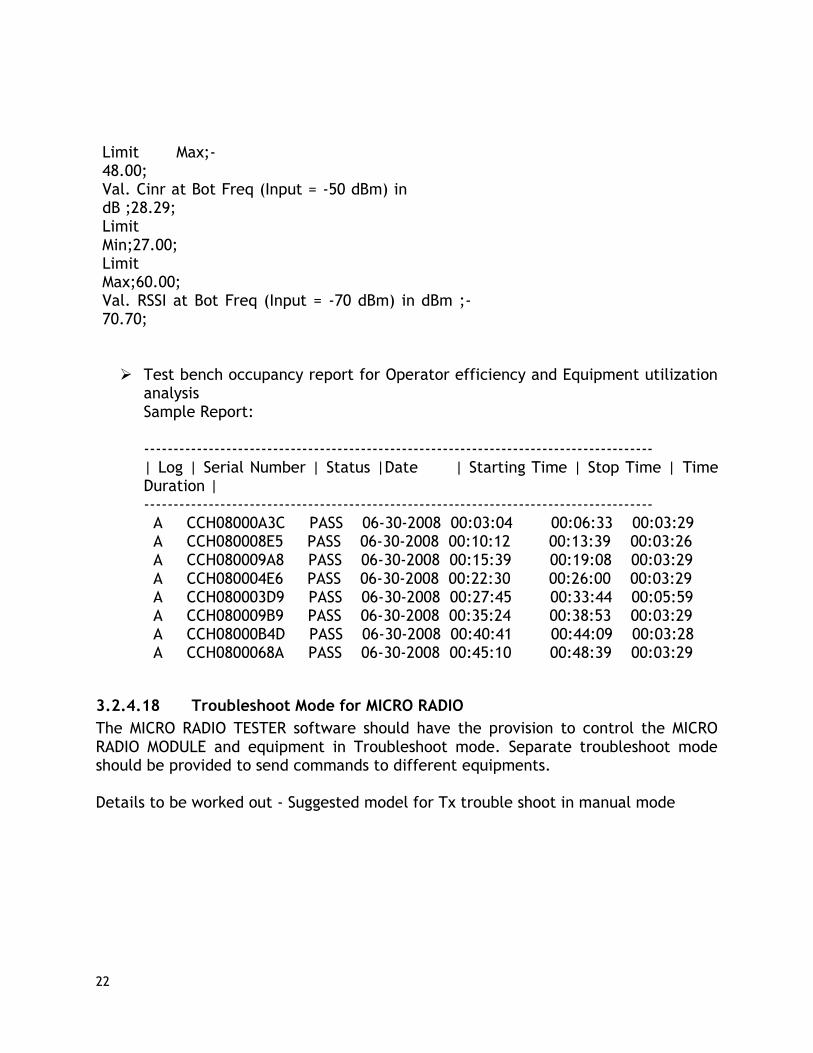
Limit Max;-48.00; Val. Cinr at Bot Freq (Input = -50 dBm) in dB ;28.29; Limit Min;27.00; Limit Max;60.00; Val. RSSI at Bot Freq (Input = -70 dBm) in dBm ;-70.70;
Test bench occupancy report for Operator efficiency and Equipment utilization analysis Sample Report: --------------------------------------------------------------------------------------- | Log | Serial Number | Status |Date | Starting Time | Stop Time | Time Duration | --------------------------------------------------------------------------------------- A CCH08000A3C PASS 06-30-2008 00:03:04 00:06:33 00:03:29 A CCH080008E5 PASS 06-30-2008 00:10:12 00:13:39 00:03:26 A CCH080009A8 PASS 06-30-2008 00:15:39 00:19:08 00:03:29 A CCH080004E6 PASS 06-30-2008 00:22:30 00:26:00 00:03:29 A CCH080003D9 PASS 06-30-2008 00:27:45 00:33:44 00:05:59 A CCH080009B9 PASS 06-30-2008 00:35:24 00:38:53 00:03:29 A CCH08000B4D PASS 06-30-2008 00:40:41 00:44:09 00:03:28 A CCH0800068A PASS 06-30-2008 00:45:10 00:48:39 00:03:29
3.2.4.18 Troubleshoot Mode for MICRO RADIO
The MICRO RADIO TESTER software should have the provision to control the MICRO RADIO MODULE and equipment in Troubleshoot mode. Separate troubleshoot mode should be provided to send commands to different equipments. Details to be worked out - Suggested model for Tx trouble shoot in manual mode

23
Figure 10: Tx Gain Selector option
is to enable TX gain value.
Figure 11: Tx test Execute option is to
execute the MICRO RADIO Transmit test.
3.2.4.19 Parameter File Entry and Edit option
The MICRO RADIO TESTER software should be able to access and modify the parameter file. The parameter file should be stored in encrypted format. Based on user’s security level, the above functionality can be enabled or disabled.
3.2.4.20 Error Handling
Errors displayed in the MICRO RADIO TESTER software are handled as follows: For any violation of the MICRO RADIO TESTER functionality described in this
document, errors are displayed at the ‘error out’ cluster Errors displayed in error-out cluster will have an error code, error status and a
description associated with the error Error code can be system defined or user defined. No pop up message/dialog box is displayed to report errors.
3.2.5. User Interface Requirements
Set up window – In case of multiple types of devices Test limit entry Test selection entry Equipment selection – to be discussed Debug mode Path calibration Equipment internal alignment init.

24
Figure 12

25
Figure 13
3.3. Design Requirements The software does not use any existing software or design component.
3.4. Testing Requirements The unit & integration testing of MICRO RADIO TESTER software will be done in a specified environment. Any special testing requirement that is needed will be listed out subsequently. Lab VIEW provides error-out cluster which is used to find out the operational abnormalities.
3.5. Deliverables The Lab view Development environment will be used to develop the MICRO RADIO TESTER software. The final delivery of the software will be an executable version and requires no development license.

26
3.6. Test Organization RF equipment and Power supply with required specifications will be configured to measure all parameters. RF cables and accessories will be configured having board specification to enable smooth measurement of RF parameters.
3.7. RF Equipment Requirements To be worked out in detail with options.
3.8. Power Supply Requirements 48 VDC, 5A programmable power supply with low ripple and noise will be required for powering the board and unit under test. Four wire connections will be used for compensating cable losses. Voltage settings and current measurements will be done from test software during automated testing.
3.9. Test Fixture Requirements Currently not considered.
3.10. Test Computer Requirements The industrial computer used in test system will have maximum processor speed, sufficient memory to handle the testing in an automated environment with maximum speed. It should have several PCI slots to handle existing requirements and should be scalable for future expansion. Interface requirements include two LAN, Serial, GPIB and NI DAQ.
3.11. Serial No. Scanning, Label Printing In the automated environment, USB barcode scanners with individual test benches will be required to record the identification of each unit prior to testing.
3.12. Cable Loss Calibration

27
The RF path loss in Tx and Rx modes will be measured and accounted for during each measurement. The calibration process is repeated with a comfortable interval of three months (TBD).
3.13. Automated Testing The whole test process will run as automated sequences. The test sequences need to be grouped to better utilize equipment and optimize test timings. Different hardware platforms for grouping test cases will be designed during test development. Automated testing provides operator independent measurements and faster test timings. This in turn enables better equipment utilization.
3.14. Documentation Documents need to be generated at every stage of test design. These include a test requirements document with a list of tests, Test architecture document with specification of individual building blocks, test software specifications document and Test limit files with final values.

28
4.0. Diagnostic Requirements
The test set up should have a diagnostic menu for fault finding of Test hardware. We should be able to call different debug routines such as audio, RF and fixture for fault finding of individual hardware blocks associated with the test system. Also it is required to simulate some static conditions for debugging. The test system must support the debugging of failed Micro radio modules. The test solution should be able to simulate all required conditions to probe and identify those sections and components of the board/unit that need replacement or rectification.

29
5.0. Traceability
Traceability from the test requirement document to subsystem level specification has to be ensured. Similarly, the subsystem level specification should connect to the reference documents which it refers.