RRD-GAS-02 SINKHOLE WATER QUALITY DEPTH PROFILE SAMPLING · RRD-GAS-02 SINKHOLE WATER QUALITY DEPTH...
27
RRD No. RRD-GAS-02 BRCTaskID GAS-04 Version Draft 1 PcSaty Date of Revision 6/27/ 2013 RRD-GAS-02 SINKHOLE WATER QUALITY DEPTH PROFILE SAMPLING SEVENTH AMEND. EMERGENCY DEC. EXHIBIT ‘A” This Recommended Requirements Document (RRD) is intended to define the minimum technical requirements for conducting the subject work tasks. This is not a work plan for conducting the work.
Transcript of RRD-GAS-02 SINKHOLE WATER QUALITY DEPTH PROFILE SAMPLING · RRD-GAS-02 SINKHOLE WATER QUALITY DEPTH...

RRD No. RRD-GAS-02BRCTaskID GAS-04Version Draft 1
PcSaty Date of Revision 6/27/2013
RRD-GAS-02
SINKHOLE WATER QUALITY DEPTH PROFILE SAMPLING
SEVENTH AMEND. EMERGENCY DEC.EXHIBIT ‘A”
This Recommended Requirements Document (RRD) is intended to define the minimum technical requirements for conducting the subjectwork tasks. This is not a work plan for conducting the work.

Blue RibbonRRD No. RRD-GAS-02
Commission BRC Task ID GAS-04OflBJCfle
Version Draft 1dd SayouPttcSaty
Date of Revision 6/27/2013Page lof3
RECOMMENDED REQUIREMENTS DOCUMENT
Subject: Sinkhole Water Quality Depth Profile Sampling
1.0 Background
The Blue Ribbon Commission (BRC) Gas Group recommends that reducing and maintaining methane gasformation pressures in the Mississippi River Alluvial Aquifer (MRAA) to equal to hydrostatic pressureacross the Bayou Come gas area as one metric necessary in order to lift the mandatory evacuationorder. This Recommended Requirements Document (RRD) defines the technical requirements forobtaining sinkhole depth profile water quality data needed to address this overall objective. The intentof this RRD is to provide recommended requirements for use by the appropriate state agencies whendirecting the development of a comprehensive work plan for addressing the RRD objective.
This RRD for collecting sinkhole water quality depth profile data has been prepared with considerationof the following site conditions and data requirements:
• Since the formation of the sinkhole, natural gas and crude oil have been percolating up fromdepth and into the sinkhole waters. During periodic sinkhole “burps” where the amount of gasmigration to the surface appears to increase, trees and other debris float to the surface for ashort period of time, and the amount of crude oil on the surface of the sinkhole also typicallyincreases.
• The available water quality data from the sinkhole illustrate that there is a substantialdegradation of water quality from the surface to the 100-foot water depth in the sinkhole withtotal dissolved solids concentration increasing from approximately 5,000 mg/L at the surface toover 50,000 mg/L at a depth of 100 feet (Hecox and Saxton, 2013).
• Establishing a more complete chemical profile of the sinkhole water quality including dissolvedgas concentration will provide a more defined picture of the water column in the sinkhole andwill help to determine if the water column contains distinct layers or if there is a chemicalgradient throughout the water column.
• The potential exists that reducing conditions in the bottom of the sinkhole are conducive tomicrobial degradation of sulfate in the presence of methane is producing hydrogen sulfide in thedeeper portions of the sinkhole. This sampling will determine if this is occurring and quantifyhydrogen sulfide concentrations, if any.
• Data collected from monthly sampling will be used to monitor changes in the sinkhole waterquality and how sinkhole events, such as the periodic “burps” or subsidence events, affect thechemical composition of the sinkhole waters.
This RRD has been prepared as part of the overall GAS-04 BRC task. This BRC task addresses the needfor chemical constituent concentration data in the sinkhole water for use in quantitative evaluations of
This Recommended Requirements Document (RRD) is intended to define the minimum technical requirements for conducting the subjectwork tasks. This is not a work plan for conducting the work.

RRDNo. RRD-GAS-02BRC Task ID GAS-04Version Draft 1
Safety Date of Revision 6/27/2013Page 2of3
gas migration and mitigation. The quantitative evaluation requirements are addressed in other RRDs.This RRD establishes the procedures and equipment required to collect these data.
2.0 Objective and Requirements
The objective of this RRD is to quantify and monitor the inorganic and organic chemical constituents andconcentrations in the sinkhole for the entire water column from the water surface to the bottom of thesinkhole. The specific laboratory and testing programs shall be specified in the work plan addressingthis RRD.
3.0 Requirements
The requirements of this RRD for sinkhole water quality depth profile data are:
1. Conduct monthly sinkhole depth-profile water and dissolved gas sampling of the water columnfrom the surface to the bottom of the sinkhole. Due to ongoing changes in the sinkholeconfiguration, the location of the deepest portion may change over time. As such, the locationof the deepest portion for a given sampling event will be determined by the results of the mostcurrent bottom survey conducted prior to each sampling event.
2. Field water quality parameters shall be measured and include pressure, specific conductance,temperature, pH, dissolved oxygen (DO), turbidity, and oxidation-reduction potential (ORP).
3. Water samples shall be collected at the water surface and at 25-foot depth intervals down tothe bottom of the sinkhole.
4. Water and dissolved gas samples should be analyzed for parameters in Table 1. As data areobtained, this parameter list can be adjusted. Both total and dissolved (0.45 t filter) metals shallbe analyzed.
This Recommended Requirements Document (RRD) is intended to define the minimum technical requirements for conducting the subjectwork tasks. This is not a work plan for conducting the work.

iuen
RRD No. RRD-GAS-02Commission BRC Task ID GAS-04onBayouCome
Version Draft 1ai Grad B5ouPflc Safety Date of Revision 6/27/2013
Page 3of3
Table 1. Sinkhole Water Quality Laboratory Analyte List
Major Ions andOrganicGas Analysis Trace Metals General ParametersCompounds
Total Alkalinity (as Total PetroleumArgon AluminumCaCO3) Hydrocarbons, GRO
Alkalinity, Bicarbonate Total PetroleumButane Antimony(as CaCO3) Hydrocarbons, DRO
Alkalinity, CarbonateCarbon Dioxide Arsenic Aliphatic C6-C8(as CaCO3)del 13C1 Barium Calcium Aliphatic >C8-C1Odel 13C2 Beryllium Chloride Aliphatic >C1O-C12del 13C3 Boron Magnesium Aliphatic >C12-C16del 131C4 Bromide Potassium Aliphatic >C16-C35del 13NC4 Cadmium Sodium Aromatic >C8-C1Odel Dcl Chromium, Total Sulfate (as 504) Aromatic >ClO-C12
Total Dissolved SolidsEthane Cobalt Aromatic >C12-C16(Residue, Filterable)Ethene Copper Total Suspended Solids Aromatic >C16-C21Helium Iron Water Density Aromatic >C21-C35Hexanes + heavier Lead BenzerieHydrogen Lithium Ethylbenzenehydrogen Sulfide Manganese TolueneIsobutane Mercury Xylene, totallsopentane NickelMethane SeleniumNitrogen SilverOxygen StrontiumPentane ThalliumPropane VanadiumPropene Zinc
Specific Gravity
Appendix 1 presents suggested procedures for data collection to meet the above objective andrequirements. These procedures can be modified or replaced as appropriate to meet the objectives andrequirements.
This Recommended Requirements Document (RRD) is intended to define the minimum technical requirements for conducting the subjectwork tasks. This is not a work plan for conducting the work.

RRD No. RRD-GAS-02lue Ribbon
BRC Task ID GAS-04
Version Draft 1PC SSfSty
Date of Revision 6/27/2013
APPENDIX 1
SUGGESTED PROCEDURES
This Recommended Requirements Document (RRD) is intended to define the minimum technical requirements for conducting the subjectwork tasks. This is not a work plan for conducting the work.

RRD No. RRD-GAS-02BlueRibbon BRC Task ID GAS-04Commissionon Bayou Cne Version Draft 1
Date of Revision 6/27/2013Page lof7
1.0 Introduction
This appendix is intended for use as a procedural reference for obtaining the data required in the RRD.The procedures in this section have been used by one or more Blue Ribbon Commissioners to obtain orgenerate the data specified in Section 3.0 of the RRD. In preparing the work plan to address this RRD,other procedures can be used provided the objectives and data requirements in Sections 2 and 3 aremet.
2.0 Contract Services
2.1 Isotech Laboratories, Inc.Water samples submitted for compositional gas analysis and isotopes should be submitted to IsotechLaboratories, Inc. in Champaign, Illinois or an equivalent laboratory specializing in analysis of dissolvedgases.
2.2 Louisiana Accredited Analytical LaboratoryWith the exception of samples submitted for compositional gas analysis and isotopes, all other samplessubmitted for laboratory analysis should be analyzed by a laboratory accredited under the LouisianaDepartment of Environmental Quality’s (LDEQ) Louisiana Environmental Laboratory AccreditationProgram (LELAP).
3.0 Specialized Field Equipment
3.1 Boat Equipped with a Sample Winch/Depth MeterThe sampling boat shall be equipped with a manual or electric sample winch with the cable marked infeet or an attached depth counter. The winch should have a minimum of 300 feet of cable. A secondsupply boat is recommended for handling decontamination activities and storage of sample coolers,sample containers, and sampling supplies.
3.2 TagLineA tag line, with a minimum of 500 feet of line weighted at the end and marked in feet and tenths of feetor equivalent, should be provided for depth measurements.
3.3 In-Situ TrolI 9500 and Rugged Reade,The In-Situ Troll® 9500 with cable-coupled RDO dissolved oxygen sensor (http://www.insitu.com/products/water-guality/troll-9500-sensors/rdo-sensors-for-the-troll-9500) and 9500 magneticstirrer, is a water quality instrument that can measure up to nine (9) water quality parameters which canbe recorded and saved on the Rugged Reader®. At a minimum the following water quality parametersshould be measured in the sinkhole: pressure, pH, temperature, conductance, DO, ORP, and turbidity.The Troll is programmed and data recorded with a Rugged Reader or smarTROLL iPhone app.
This Recommended Requirements Document (RRD) is intended to define the minimum technical requirements for conducting the subjectwork tasks. This is not a work plan for conducting the work.

RRD No. RRD-GAS-02Blue Ribbon BRC Task ID GAS-04Commissionon Bayou Cmie Version Draft 1
Date of Revision 6/27/2013
Page Zof7
3.4 Van Dorn SamplersVan Dorn-style samplers are recommended to collect samples at various depths of the water column tomaintain integrity of the dissolved gases in the water sample. The sampler should have a minimum of4.2 liter capacity although the 6.2 liter sampler may reduce field time if a properly configured winch isused. A vertical Van Dorn sampler is recommended as this allows for easier dissolved gas sampleretrieval. Two Van Dorn samplers are recommended to allow for one to be decontaminated while theother one is being used to collect a sample.
3.5 Sample Filtering EquipmentPeristaltic pump and 0.45 micron high-capacity filters and tubing should be provided in sufficientquantity for the number of anticipated samples.
3.6 Sampling SuppliesAppropriate sample containers (sufficient quantity for the number of anticipated samples), coolers,labels, chain-of-custody forms, nitrile or latex gloves, and miscellaneous sampling supplies should beprovided.
3.7 Decontamination SuppliesAppropriate tubs, brushes, decon fluids (distilled or deionized water, Alconox soap or equivalent),brushes, paper towels, and foil should be provided. It is recommended that a decon station be set up ona second boat for this sampling.
3.8 GPS UnitA portable global positioning system (GPS) unit with sub-meter accuracy and real-time trackingcapability is recommended.
This Recommended Requirements Document (RRD) is intended to define the minimum technical requirements for conducting the subjectwork tasks. This is not a work plan for conducting the work.

RRD No.BRC Task IDVersion
Date of Revision
Page
RRD-GAS-02GAS-04Draft 1
6/27/2013
3 of 7
The following definitions are applicable to this appendix:• Van Dorn Sampler—specialized sampling device capable of collecting dissolved gas and water
samples at a specific depth.
Figure 1. Vertical Van Dorn sampler
• LELAP— Louisiana Environmental Laboratory Accreditation Program. Laboratory data generatedby commercial environmental laboratories that are not accredited under these regulations willnot be accepted by the department in accordance with LAC 33:l.4501.A.2. Whenever samplesare subcontracted to another environmental testing laboratory, the original laboratory shallmaintain a verifiable copy the results with a chain of custody. The procedure may not be used tocircumvent proper accreditation or any state requirements. The original laboratory isresponsible for ensuring that the secondary laboratory used is properly accredited for the scopeof testing performed in accordance with LAC 33:l.5307.D.
5.0 Procedure
The following procedures are recommended for the collection of depth-profile water quality samplesfrom the sinkhole. These procedures are based on previous experience with sampling surface water andwater at depth along the Louisiana Gulf Coast. The sampling should be conducted using a primarysample boat with a second supply boat for handling decontamination, sample coolers, ice, and bottles.
5.1 Sinkhole Access/Seismic ClearanceBefore launching the boats, meet with the site seismic monitoring authority to obtain the currentSeismic Activity Level Code which will indicate if personnel can enter and perform work on the sinkhole.The depth-profile sampling can only be conducted during periods when the Seismic Activity Level Codeis at Level 1/Green. A competent and knowledgeable person should monitor the seismic helicorderswhen personnel are working on the sinkhole. Cell-phone or QEP radio communications will be usedduring the sampling.
Blue RibbonCommissionon Bayou Coned Orand Bayou
PiOC Saty
4.0 Definitions
This Recommended Requirements Document (RRD) is intended to define the minimum technical requirements for conducting the subjectwork tasks. This is not a work plan for conducting the work.

RRD No. RRD-GAS-02Blue Rbboii
BRC Task ID GAS-04Commissionon Beyou Come Version Draft 1
Date of Revision 6/27/2013Page 4of7
5.2 Route and Sample Location TrackingUpon leaving the boat launch, turn on the GPS unit in tracking mode and allow it to record the track ofthe entire sample event. Place the unit in the location where it has a clear signal from the sky, awayfrom any other electronic or magnetic equipment that could cause interference, but is out of the wayfor sampling. Turn the unit off only after sampling is complete and the boats are back at the dock.
53 Boat Positioning/Sample LocationPosition the sampling boat over the deepest depth location in the sinkhole, based on the most recentdepth profiles. Since it may not possible to anchor the boats, procedures for maintaining proper locationover the deepest part of the sinkhole should be coordinated with the boat operators.
5.4 Depth GaugingOnce the boat has been positioned over the deepest part of the sinkhole, sound the bottom of thesinkhole using the tag line. Record the depth of the sinkhole at this location.
5.5 Water Quality MeasurementsWith the In-Situ, Inc. Trolls 9500, measure pressure, pH, specific conductance, temperature, DO,turbidity, and ORP at 10-foot depth intervals from the water surface down to just above the bottom ofthe sinkhole. Attach the tag line to the Troll® sensor for measuring the depth—it is not possible to usepressure to determine depth because of the variable density water in the sinkhole. Use the Troll®logging function (In-Situ, Inc. Rugged Reader® required) to continuously record the data and write downthe final values at each 10-foot depth interval on the sample collection log. It may take several minutesfor the DO and ORP readings to stabilize at a given depth; the magnetic stirrer facilitates stabilization.
5.6 Surface Water Sample CollectionUsing a peristaltic pump and new, clean Teflon tubing, collect water and dissolved gas samples atapproximately 1-foot below the water surface. Place the proper aliquots in the labeled sample bottles.Filter the sample that will be submitted for dissolved metals analysis. Use the Isobag and peristalticpump for collecting the dissolved gas samples.
5.7 Depth Profile Water Sample CollectionUsing the Van Dorn sampler (Lane et al., 2003), collect depth profile water samples at depths of 10 feet,25 feet, 50 feet, and every 25 feet thereafter to the bottom of the sinkhole. The last sample should beapproximately 5 feet above the bottom of the sinkhole. As a guide for the final sample, if the bottom ofthe sinkhole is at 160 feet, it is not necessary to collect a sample at 155 feet and the 150-foot sample willbe the bottom sample. If the bottom of the sinkhole is at 165 feet, then the bottom sample will becollected at the 160-foot depth.
This Recommended Requirements Document (RRD) is intended to define the minimum technical requirements for conducting the subjectwork tasks. This is not a work plan for conducting the work.

RRD No. RRD-GAS-02Blue Ribbon
BRC Task ID GAS-04Commissionon Bayou Ccxne Version Draft 1
Date of Revision 6/27/2013Page 5of7
It is important that the boat location be maintained close to the deepest portion of the sinkhole duringall sampling. It is recommended that the GPS unit be operated in tracking mode to document anychanges in boat location during the sampling events.
A water sample at the selected depths should be collected as follows using a Van Dorn sampler whichhas been properly decontaminated. Any sampling personnel that will come into contact with thesampling device and/or sampling containers shall wear a new, clean pair of nitrile or latex gloves duringall sampling activities. The gloves should all be changed in between each sample. Below are the generalsampling procedures that are recommended:
1. Confirm that the winch cable is securely attached to the sampling device. Check that thesample valves (located on the sampler end caps) on the Van Dorn sampler are both closed. Setthe end cap trigger mechanism as per manufacturer instructions.
2. Using the winch with depth meter on the boat, lower the Van Dorn sampler to the targetdepth. Make sure that the rope attached to the sampler is free of knots and kinks so that themessenger (weighted cylinder) can reach the sampling device.
3. Upon reaching the desired depth, release the messenger (weighted cylinder) to trigger theclosing of the sampler end caps.
4. Retrieve the Van Dorn sampler into the boat using the winch.
5. Hold the sampling device in the vertical position then open the top sample port. The samplerwill be under pressure and so caution must be used when opening the valves.
6. Open the bottom valve and using the attached sample port and Teflon tubing, fill thedissolved gas Isobag first followed by the VOC vials. As pressure is relieved in the Van Dornsampler, open the top sample port to allow for water flow out of the bottom port.
7. New Teflon tubing will be used for each new sample depth.
8. After these samples are collected, fill the appropriate bottles including the filtered dissolvedmetals container. For dissolved metals, it is preferable to connect tubing to the bottomsample port and pump directly from that port, through the filter into the sample bottle.
9. Properly label each sample at the time of collection. At a minimum, the label should containthe following information: Sample l.D., Depth, Date and Time collected, Sampler’s name,requested analysis.
10. Except for the Isobags, samples will be placed on ice in coolers immediately following samplecollection.
11. The sampler will hold approximately 4 or 6 liters of water. Make repeated trips to the sampledepth as necessary to fill all sample bottles.
12. Decontaminate the sampler on the decon boat using the proper materials and procedures.Because there will likely be oil film on the sampler, a mild (phosphate-free) detergent may benecessary for thorough decontamination. Two samplers are recommended so one can bedecontaminated while the second on is being used for sampling.
This Recommended Requirements Document (RRD) is intended to define the minimum technical requirements for conducting the subjectwork tasks. This is not a work plan for conducting the work.

RRD No. RRD-GAS-02BlueRibbonBRC Task ID GAS-04Commission
on sayou Cc*ne Version Draft 1Date of Revision 6/27/2013Page Gof7
5.8 Sample Handling and ShipmentUpon returning to the dock, pack the samples for shipping to the appropriate laboratory. Add ice ifnecessary/required. Complete the Chain-of-Custody forms. Transport the samples to the laboratory,laboratory courier, or shipper (i.e. Fed-Ex or UPS).
5.9 Sample AnalysisThe water samples from each sample depth will be submitted to the appropriate laboratories, followingproper chain-of-custody procedures, for analyses. The following analyses will be requested:
5.9.1 Isotech LaboratoriesThe Isobags should be submitted to Isotech Laboratories in Champaign, Illinois or equivalent dissolvedgas laboratory for analysis of:
• Compositional Gas (see Table 1 for list of components)
• Compound-specific isotope Ratios (see Table 1 for list of isotopes)
5.9.2 LELAP LaboratoryThe remaining samples from each depth should be submitted to the selected LELAP laboratory for thefollowing analyses:
• Alkalinity by Method 2320 or equivalent
• Benzene, Toluene, Ethylbenzene, Xylene (BTEX) by U.S. Environmental Protection Agency (EPA)Method 8260 or equivalent
• Chloride by Method SM4500 or Method 9056 or equivalent
• Inorganic Anions by Method 9056 or equivalent
• Metals (dissolved and total) — EPA Method 6010 or equivalent (see Table 1 for metals list)
• Specific Conductance by Method SM2S1O or equivalent
• Total Dissolved Solids by Method SM2540 or equivalent
• Total Petroleum Hydrocarbons — Gasoline Range Organics/Diesel Range Organics/Oil RangeOrganics by EPA Method 8015 or equivalent
• Total Petroleum Hydrocarbon fractions (aliphatics >C6—C35, and aromatics >C8—C35) byMassachusetts TPH Method
• Total suspended solids by Method 160.2 or equivalent
• Water density by hydrometer or equivalent
5.10 Equipment DecontaminationAt the conclusion of the sampling event, all sampling equipment should be thoroughly decontaminatedand placed in proper storage pending future sampling. All disposable equipment shall be properlydisposed.
This Recommended Requirements Document (RRD) is intended to define the minimum technical requirements for conducting the subjectwork tasks. This is not a work plan for conducting the work.

RRD No. RRD-GAS-02BliieRibbon BRC Task ID GAS-04Commissionon Bayou Cc*ne Version Draft 1
Date of Revision 6/27/2013Page 7of7
5.11 Submittal of DataAll field activities should be documented and reported to LDNR in an electronic format and reasonabletime frame. Upon receipt, analytical results shall also be submitted to LDNR in PDF and Excel or similarelectronic data transfer format.
6.0 Attachments
• Attachment 1—Isobag fill procedures
7.0 Forms
• Daily Field Activity Log
• Chain-of-Custody Document
• Sample Collection Log
8.0 References
Hecox, G. A., and Saxton, D. C., 2013, Bayou Come Sinkhole Status Report to Blue Ribbon Commission,Baton Rouge, LA, CB&I, 121 plus appendices p.:
Lane, S. L., Flanagan, S., and Wilde, F. D., 2003, Chapter A2, Book 9, Selection of Equipment For WaterSampling, Handbooks for Water-Resources Investigations, National Field Manual for theCollection of Water-Quality Data, Reston, VA, U.S. Geological Survey, v. A2, 123 p.:
This Recommended Requirements Dotument (RRD) is intended to define the minimum technical requirements for conducting the subjectwork tasks. This is not a work plan for conducting the work.

RRD No. RRD-GAS-02BlueRibbon BRC Task ID GAS-04CommissionoayouCcme Version Draft 1
Date of Revision 6/27/2013
ATTACHMENT 1
ISOBAG FILL PROCEDURES
This Recommended Requirements Document (RRD) is intended to define the minimum technical requirements for conducting the subjectwork tasks. This is not a work plan for conducting the work.
1lQgcjiISOTECH LABORATORIES INC
1308 PjikInd (curt Chafl )mcjn, IL 61821 877 362-419(1 cj’.;v.isotecI,ibscom
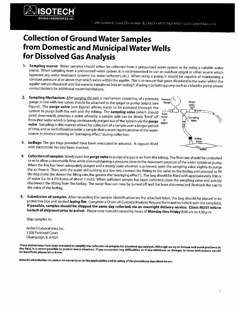
Collection of Ground Water Samplesfrom Domestic and Municipal Water Wells.for Dissolved Gas Analysis1. Sampling source: Water samples should either be collected from a pressurized water system or by using a suitable water
pump. When sampling from a pressurized water system, it is recommended to use an outdoor spigot or other source whichbypasses any water treatment systems (i.e. water softeners, etc.). When using a pump, it should be capable of maintaining aconstant pressure at or above that which exists within the aquifer. This is to ensure that gases dissolved in the water within theaquifer remain dissolved until the water is transferred into an IsoBag®. If using a pulsating pump such as a bladder pump, pleasecontact lsotech for additional recommendations.
2. Sampling Mechanism: After purging the well, a mechanism consisting of a pressuregauge in line with two valves should be attached to the spigot or pump output (seefigure). The purge valve (see figure) allows water to be pumped through thesystem to purge both the well and the tubing. The sampling valve (which should Frompoint downward), provides a point whereby a sample split can be slowly “bled” off I’unpfrom that water which is being continuously purged out of the system via the purgevalve. Sampling in this manner allows for collection of a sample over a longer periodof time,and as such should provide a sample that is more representative of the watersource, in essence creating ari”averaging effect”during collection.
3. IsoBags: The gas bags provided have been evacuated in advance. A capsule filledwith bactericide has also been inserted.
4. Collection of samples: Slowly open the purge valve to purge any gas or air from the tubing. The flow rate should be controlledso as to allow a reasonable flow,while also maintaining a pressure close to the maximum pressure of the water system or pump.When the line has been adequately purged and a steady state situation is achieved, open the sampling valve slightly to purgethe air from it. Then, with the water still running at a low rate, connect the fitting to the valve on the lsoBag and proceed to fillthe bag (note: the slower the filling rate, the greater the “averaging effect”). The bag should be filled with approximately 500 ccof water (i.e.to a thickness of about 1 inch). When sufficient sample has been collected, close the sampling valve and quicklydisconnect the fitting from the lsoBag. The water flow can now be turned off and the hose disconnected. Reattach the cap tothe valve of the lsoBag.
5. Submission of samples. After recording the sample identification on the attached label, the bag should be placed in itsprotective box and packed laying flat. Complete a Chain-of-Custody/Analysis Request form and include it with the sample(s).If possible, samples should be shipped the same day collected, via an overnight delivery service. Client MUST informIsotech of shipment prior to arrival. Please note Isotech’s receiving hours of Monday thru Friday 8:00 am to 4:30 p.m.
Ship samples to:
Isotech Laboratories, Inc.1308 Parkland CourtChampaign, IL 61821
These instructions have been provided to simplify the collection of samples for dissolved gas analysis. Although we try to foresee and avoid problems inthe field, it is never possible to predict every situation. If you encounter any difficulties, or if any additions or changes in these instructions wouldbe beneficial, please let us know.
PressureGauge
lsotech Laboratories, Inc. makes no warranty as to the applicability and/or safety of the procedures described herein.

From: Michael TaylorSent: Tuesday, July 02, 2013 8:04:38 AM (UTC-06:00) Central Time (US & Canada)To: conservationorder; Gary Snellgrove; Gary Hecox; deborah.saxtonshawaro.com; John Boudreaux; Travis Williams;[email protected]: Bruce Martin; Mark Cartwright; Troy CharpentierSubject: Fw: Comments on BRC RRD-GAS-002 Sinkhole Water Quality Depth Profile Sampling
Team,
I inadvertently left you off of this email.
Thanks,
mt
Michael Taylor, P.C.; P.E.A.Grand Bayou Response Manager901 -482-2500
Forwarded by Michael Taylor/UNITED on 07/02/2013 08:03 AM
From Michael Taylor/UNITEDTo Donald Haydel” <DonaId.HaydeI(LAGOV>,Cc Bruce Martin1UNITED@UNITED, Mark CartwrightlUNlTED@UNITED, Dave Angle’ <danQlec.mDisanicom>, pritchiemoisani.com, MauriceValentine/UNITED, Stella Williams/IJNITED@UNITEDDate 07/02/2013 08:02 AMS:bject Comments on BRC RRD-GAS-002 Sinkhole Water Quality Depth Profile Sampling
Don,
I have attached our consultants (Pisani) comments and questions on the BRC RRD 002 for distribution to the BRC.
After review of the Blue Ribbon Commission (BRC) Recommended Requirements Document pertaining to the sinkholeprofiling we provide the following comments.
The scope of work outlined in the BRC document will require MP&A and other field personnel (i.e. air boat, CB&I, etc.) tobe located on the sinkhole for a longer period of time, likely an entire day versus approximately 2-3 hours during ourcurrent sampling program. To date, we have attempted to minimize the time anyone is on the sinkhole for safetypurposes. The BRC proposed monthly sampling can be done but the sampling schedule will still be subject to theAssumption Parish Emergency Response Status Code (i.e. no sampling would be conducted when the Status Code is a 2or 3).
SEVENTH AMEND. EMERGENCY DEC.EXHIBIT “B”

We have also noted the following items, some of which will increase the time and number of personnel it will take tocomplete each sampling event, that will need to be worked out:
1.) Additional equipment will need to be purchased and/or rented (i.e. 500’ tag line, Troll 9500 and Rugged Reader, 2Van Darn Samplers, Teflon tubing, sub meter accuracy GPS unit)
2.) Who will be the site seismic monitoring authority? Dr. Hecox and/or John Boudreaux, or is Texas Brine’s Contractorresponsible for this function?
3.) TBC will have Miller Engineering locate the deepest location, either through marking the location with a buoy or asuspended line over the sinkhole with appropriate markers. This would limit the amount of time needed by the samplingteam to be located on the sinkhole and provide an anchor/location point for the airboats.
4.) In order to complete the required tasks outlined, it appears that the sampling boat will require at least 2 individualsand the support boat will require 1 individual for decontamination.
5.) It appears that the requested sampling methodology will take a greater amount of time due to the increasedparameter list (i.e. more sample bottles required) and decontamination of the sampler.
6.) The attached BRC constituent list has been highlighted to indicate which constituents we are currently analyzing. Asthis highlighted version demonstrates there are many additional constituents that the BRC is requesting.
7.) Finally, the BRC is requesting monthly profiling events; however, the August, October, and November 2012 andApril 2013 sinkhole profiling data we have gathered to date indicate generally similar results (i.e. higher concentrations ofchloride and other constituents with depth); therefore, it seems like quarterly data could suffice.
In summary, the extensive BRC sampling program is more suited for a quarterly schedule to limit the amount of time fieldpersonnel are located over the sinkhole. However, in consideration of the BRC’s monthly sampling request, we proposeto conduct two monthly events during Status Code No. 1 time periods and compare the monthly data to the data sets thathave been gathered to date. If this data evaluation indicates generally consistent results then we propose to conductquarterly sampling going forward into the future. We are not certain that collection of monthly data, regardless of whatthe data would ultimately indicate, would lead to a different long term containment/control response.
We are available to conduct the first monthly profiling event during the end of the week of July 8th, 2013.
Thanks,
mt
Michael Taylor, P.G.; P.E.A.Grand Bayou Response Manager901 -482-2500
This e-mail and any attached files may contain CB&I (or its affiliates) confidential and privileged information.This information is protected by law and/or agreements between CB&I (or its affiliates) and either you, youremployer or any contract provider with which you or your employer are associated. If you are not an intendedrecipient, please contact the sender by reply e-mail and delete all copies of this e-mail; further, you are notified
2

that disclosing, copying, distributing or taking any action in reliance on the contents of this information isstrictly prohibited.
3

Blue Ribbo RRD No. RRD-GAS-008Commission BRC Task ID GAS-iCon Sayon Cc%ne
and Grand Baron Version Draft 3PjO,c SaIty
Date of Revision 6/4/2013
Page 1
RRD-GAS-008A
EXTENT OF GAS
SUBSLAB PRESSURE MONITORING
SEVENTH AMEND. EMERGENCY DEC.EXHIBIT C”
This Recommended Requirements Document (RRD) is intended to define the minimum technical requirements for conducting the subjectwork tasks. This is not a work plan for conducting the work.

Ribbo RRD No. RRD-GAS-008Commission BRC Task ID GAS-bon bayou Come
end O’nnd Bacu Version Draft 3PL4’C saret7Date of Revision 6/4/2013
Page bofi
RECOMMENDED REQUIREMENTS DOCUMENT
Subject: Subsiab Differential Pressure Monitoring
1.0 BACKGROUND
The Blue Ribbon Commission Gas Group has agreed to recommend that reducing and maintainingmethane gas formation pressures in the Mississippi River Alluvial Aquifer (MRAA) to equal to or less thanhydrostatic pressure across the Bayou Come gas area is necessary in order to lift the mandatoryevacuation order. This Recommended Requirements Document (RRD) defines the technicalrequirements for obtaining ORW operational data to address this overall objective. The intent of this RRDis to provide recommended requirements for use by the appropriate state agencies when directing thedevelopment of a comprehensive work plan for addressing the RRD objective.
This RRD for collecting subslab pressure monitoring data has been prepared with consideration of thefollowing site conditions:
• There is methane gas bubbling to the surface in the community.
• Shallow well NSDMW15 in the Bayou Come community consistently has gas pressure sufficientto lift the water out of the well when the wellhead valve is opened.
• The gas in the community has been evaluated and determined to be either thermogenic or amix of thermogenic and biogenic gas.
• The gas pressure in the MRAA below the community at is at least 58 pounds per square inch(psi).
• Methane has been detected below floor slabs at two locations.
This RRD has been prepared as part of the overall GAS-08 BRC task. This BRC task addresses the extentof the gas in the MRAA and overlying aquitard and the monitoring of the gas for changes overtime. ThisRRD establishes the procedures and equipment required to determine if there is currently gas pressurebelow the floor slabs in the communities that may require long-term monitoring.
2.0 Objective and Scope
The technical objective of this RRD is to monitor differential pressures between underneath the floorslabs and the occupied spaces of homes or structures.
The geographic scope of this RRD is the slab-on-grad homes and structures in the Grand Bayou andBayou Come communities, Assumption Parish, LA. The pressure recording period should be at least oneweek to allow for a range of barometric changes to be monitored. The number of ports and locations tobe monitored must be representative of the overall site conditions in the community.
This Recommended Requirements Document (RRD) is intended to define the minimum technical requirements for conducting the subjectwork tasks. This is not a work plan for conducting the work.

RRD No. RRD-GAS-005
BRC Task ID GAS-07
Version Draft 1p Date of Revision 6/4/2013
APPENDIX 1
SUGGESTED PROCEDURES
This Recommended Requirements Document (RRD) is intended to define the minimum technical requirements for conducting the subjectwork tasks. This is not a work plan for conducting the work.

RRD No. RRD-GAS-005luc Ribbon BRC Task ID GAS-07
Version Draft 1p saet,’ Date of Revision 6/4/2013
Page lof3
1.0 Introduction
This appendix is intended for use as a procedural reference for obtaining the data required in the RRD.In preparing the work plan to address this RRD, procedures can be modified as applicable to obtain thedata necessary to address the objectives and scope in Section 2.0. Because of anticipated lowdifferential pressures, key elements to meeting the objective are the installation of sealed sample portsand the recording micromanometer.
2.0 Specialized Equipment
2.1 Sealed slab sample portsFor accurate differential pressure measurement between below the floor slab and the overlyingoccupied space, a correctly installed sealed sample port installed in the floor slab is required. It isrecommended that after the hole is drilled through the floor slab using a rota-hammer, the sample portshould be sealed into the concrete using the appropriate epoxy or similar permanent sealant.
If instrumentation-style shut-off (i.e. valved) quick connects are used, it may be advantageous topermanently install and seal a small diameter female pipe coupling into the concrete slightly below thetop of the slab. Either the male or female side of the quick connect can then be threaded into thisfemale into this coupling. Examples of instrumentation shut-off quick connects can be found atSwagelok (http://www.swagelok.com/products/quick-connects.aspx) and other specialty valve andtubing manufacturers.
If an instrumentation shut-off quick connect is not used, then a ball shut-off valve should be installed onthe top if the sample port to maintain the integrity of the system for pressure monitoring. This valveshould remain closed at all times that the sample port is not being used.
2.2 Micromanometer and recorderThe Micromanometer needs to be able to meet the pressure and data logging requirements outlined inthe definitions. Attachment 1 contains the specification sheets of two example micromanometers thatmeet the pressure requirements. One instrument has an internal data logging capabilities and the otherrequires connection to a computer to record data. The manometer should be calibrated and checkedbefore each use using a standardized pressure gauge capable of reading low pressures. The range of theinstrument should be ±1,000 Pascal (±4 inches of water column) or less with a resolution of 0.1 Pascal(0.0004 inches of water). The instrument should be capable of recording differential pressures for up toseven days at 15-minute intervals (“P700 data points). The micromanometer should be capablemeasuring and recording both positive and negative pressures.
2.3 Barometric Pressure RecorderBarometric pressure changes can affect the flow of vapor between the underside of the floor slab andthe occupied space. Therefore it is important that barometric pressure be recorded at or near the site
This Recommended Requirements Document (RRD) is intended to define the minimum technical requirements for conducting the subjectwork tasks. This is not a work plan for conducting the work.

RRD No. RRD-GAS-0O5too BRC Task ID GAS-07
Version Draft 1Pubk Saftj Date of Revision 6/4/2013
Page 2of3
throughout the monitoring period. Barometric pressure should be recorded using a standardbarometric pressure transducer and recording device. These are commonly available fromenvironmental instrument suppliers (e.g. http://www.microdaq.com/tanddltr7u/three channel data Iogger.php)
3.0 Definitions
• Micromanometer—An electronic instrument capable of measuring and recording differentialpressures down to 0.1 Pascal (0.0004 inches of water).
. Differential pressure—Differential pressure is the difference in absolute pressure between twomonitoring points. In the context of this RRD, differential pressure is the difference in theabsolute pressure between below the floor slab and the overlying occupied space.
4.0 Procedure
The steps below can be used to monitor the differential pressure between the bottom of a floor slaband the occupied space.
4.1 Step 1—Install floor probeInstall the floor sample port in the selected location in the floor slab. Care must be taken topermanently seal the port into the concrete of the slab. Epoxy of similar sealant is recommended. If aninstrument shut-in quick connect is to be used, then, depending on the quick connect being used, thefemale or male side of the quick connect is screwed into the port fitting using Teflon tape to seal thepipe threads. If a valve port is to be used, the ball or similar shut in valve should be installed on the portusing a similar connection.
4.2 Step 2—Check port for leaksAfter the port is installed, if possible it should be checked for leaks. However it is acknowledged that thefloor slab configuration might limit or prevent leak checking of the port. If it is possible to leak check theport, the applied pressure should be one inch of water column.
4.3 Step 3—Connect and configure micromanometerInstall the micromanometer on the sample port using appropriate connection tubing.
Set up the micromanometer and recording system to record and store pressures according to themanufacturer’s setup procedures. Set up the system to record on a 15-minute or less time interval.Check that the clock is set to record at local time. If
Turn the recording system on to start the monitoring period.
Check the instrument readout positive and negative pressure direction by applying very low pressure onthe end of the sample port tube. Low pressure can be done by gently blowing across the end of thesample port tube while monitoring the pressure readout. When pressure is applied to the sample port
This Recommended Requirements Document (RRD) is intended to define the minimum technical requirements for conducting the subjectwork tasks. This is not a work plan for conducting the work.

RRD No. RRD-GAS-005Blue RibbonBRC Task ID GAS-07Version Draft 1
PLhC 5tyDate of Revision 6/4/20 13Page 3of3
tube, the readout should read positive pressure. This will mean if a positive pressure is measured duringthe monitoring period, the pressure on the underside of the floor slab is higher than in the occupiedspace. This pressure check should be recorded by the recording system so that the check data areavailable in the data file.
4.4 Step 4—Check system operationAfter the system has been operational for several hours or overnight, it is important to download thedata recorder to make sure the instrument is recording data properly. If it is working properly, it can beleft unattended for the remainder of the monitoring period. If it is not working properly, then themicromanometer system must be repaired or adjusted to record the proper data.
4.5 Step 5—Download recorder and check dataAt the end of the recording period, download the data to a field computer. The data file should bechecked for completeness and integrity immediately upon downloading. The checks should include butare not limited to
• Completeness of the data record. Did the system record for the entire monitoringperiod and are the correct dates and times recorded correctly?
• Range of differential pressure values recorded. Are the differential pressures recordedin the ranges of expected values or are there outliers?
5.0 Attachments
5.1 Attachment 1There are various micromanometers with the applicable pressure ranges with recording capabilities thatcan be used for collecting the subsiab differential pressure data. Two examples of micromanometersthat can be used to measure and record the differential pressures to the precision and accuracyrequired are included in Attachment 1.
• The FCO51O (http://www.furnesscontrols.com/difpres2.htm), is an industrialmicromanometer that requires and external power supply.
• The DG-500 (http://www.energvconservatorv.com/proclucts/digftal-pressure-gauges), isa battery powered field instrument that requires a computer for data logging.
60 FORMS
None but it is suggested that a data collection form be developed to record the installation, setup, andoperation of the system.
This Recommended Requirements Document (RRD) is intended to define the minimum technical requirements for conducting the subjectwork tasks. This is not a work plan for conducting the work.

DG-500 Digital Pressure Gauge
Today’s building performance test procedures require diagnostic toolsthat are versatile, accurate and easy to use. The Energy Conservatory’snew DG-500 Digital Pressure Gauge combines all these qualitiesinto a sophisticated hand-held gauge that sets a new standard forperformance testing equipment. The DG-500’s advanced design givesyou the power and flexibility needed to handle all types of buildingperformance investigations.
The DG-500 Digital Pressure Gauge is a high resolution differentialpressure gauge with 2 independent measurement channels. The DG500’s dual pressure channels and air velocity measurement featuresmake it ideally suited for a wide range of building performance testingapplications.
• Building pressurization and depressurization mapping - Accuratelymeasure pressure imbalances from one room to another such asisolation suites or manufacturing clean rooms.
• Combustion safety testing - With 2 independent channels you candetermine the effect of exhaust fans on both the combustion flueand the appliance room.
• Air handler and duct pressure measurements - Measure totalexternal static pressure at the air handler, duct work static pressuresand air velocity to help diagnose airflow performance problems.
Quality Features• Simultaneous display of 2 independent differential pressure channels, A and B.
• Accurate pressure measurements, ± 1% of reading from —1,250 to + 1,250 Pascals, or -5 to +5 in. H20.• Auto-zeroing of both measurement channels adjusts for position and temperature during operation.• Choice of 4 time-averaging options, 1, 5, 10 second average and Long-Term or continuous average.• Choice of velocity units on Channel B, fpm or m/s.
• A HOLD button temporarily freezes the most recent displayreadings.
• The DG-500 can be used along with a computer andTECLOG for Windows® software to conduct data loggingof pressure measurements from both channels.
TECLOG is free data logging software that will record andgraphically display pressure measurements from the DG-500.TECLOG is also capable of data logging from two DG-500Gauges providing you with 4 channels of precision pressuremeasurement at a fraction of the cost of most pressure dataloggers.
The DG-500’s versatility and advanced features make it a “musthave” tool for all performance testing contractors.Diagnostic tools from The Energy Conservatory are
_______
the cornerstones to more efficient, affordable, and
________
healthy buildings and HVAC systems.
Call us for more information!
___
The ENERGYCONSERVATORYDIAGNOSTIC TOOLS TO MEASURE BUILDING PERFORMANCE

specificationsNumber of Independent Pressure Channels: 2Pressure Range: —1,250 to + 1,250 Pascals (-5 to +5 in. H20)Display Resolution: 0. 1 Pa (0.0001 in H20)Accuracy: I % of pressure reading or . 1 5 Pa, whichever is greater.Units of Measure: Channel A — Pascals, in. H20
Channel B - Pascals, in. H20, fpm, rn/sAuto-Zero: On start up and then once every 1 0 secondsTime Averaging: 1, 5, I 0 seconds and Long-Term (continuous update)Operating Temperature Range: 32° F to I 20° F (0° C to 48° C)Storage Temperature Range: -4° F to 1 60° F (-2 0° C to 7 10 C)LCD Display: 3.193 x 1.16 in. (8.11 x 2.946 cm)Display Backlight: Manually operated, timed off after 1 0 minutes.Power: 6 - ,AA alkaline batteries, supplied. AC power adapter optional.Battery Life (Alkaline): Over 100 hours continuous use.Auto-Off: After 2 hours from last keyed entry unless disabled by user.Weight: 16.5 oz. (0.468 kg)
Dimensions: 7.5 in. x4 in. x 1.25 in. (19.5 cmx 10.16 cmx3.175 cm)ModesPressure/Pressure and PressureNelocity
Data LoggingData logging of pressure measurements from both channels requires TECLOG for Windows®, available free atwww.energyconservatory.com, and a serial cable to connect the DG-500 to a computer.Digital Gauge Kit include:DG-500 Digital Pressure Gauge, protective carrying case, static pressure probe, 1 0 ft (3 rn) red hose, 1 5 ft (5 m)green hose, instruction manual, 2 year warranty.
Other building diagnostic products available from The Energy Conservatory
The Minneapolis Duct Blaster®measures the airtightness ofduct work.
The IR-lnsightTM Infrared Cameradetects hidden air leakage paths inbuilding cavities and components.
The TrL , ,G Air Handler FlowMeter measures the total amount ofair moving through an air handler
To Order, or for more information contact: The Energy Conservatory2801 2l5tAvenue South, Suite 160Minneapolis, Minnesota 55407Specifications subject to change.phone: 612—827—111 7Minneapolis Blower Door is a trademark of The Energy Conservatory.
Minneapolis Duct Blaster® and TrueFlow® are registered trademarks of The fax: 612—827—1051Energy Conservatory. Windows is a registerd trademark of Microsoft. e—mail: info®energyconservatory. corn© The Energy Conservatory Inc. 2004
website: www.energyconservatory.com

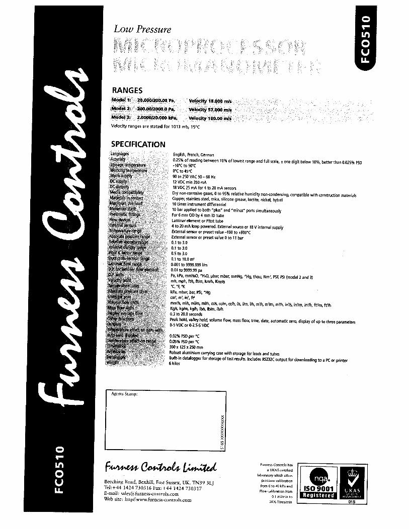
English, French, German0.25% of reading between 10% of lowest range and full scale, ± one digit below 10%, better than 0.025% FSD—lOt to 50’CO’Cto45’C90 to 250 VAC 50-60Hz12 VDC mm 350 mA18 VDC 25 mA for 4 to 20 mA sensorsDry non-corrosive gases, 0 to 95% relative humidity non-condensing, compatible with construction materialsCopper, stainless steel, mica, silicone grease, loctite, nickel, hytrel10 times instrument differential10 bar applied to both plus’ and minus ports simultaneouslyFor 6 mm GD by 4 mm ID tubeLaminar element or Pitot tube4to 20 mA loop powered. External source or 18 V internal supplyExternal sensor or preset value —100 to +800’CExternal sereoror preset valueoto 11 bar0.1 to 3.00.1 to 3.00.5 to 3.00.1 to 10.0 ma0.001 to 9999.999 lIm0.01 to 9999.99 paPa, kpa, mmHO, HaO, pbar, mbar, mmHg, uHg, thou, Nmr, PSF, PSI (model 2 and 3)mis, mph, ftfl, ftlm, krnfti, Knots‘C ‘F, ‘KkPa, mbar, bar, PSI, Hgcm’, m’, in’. ft’mmtis mIs, mum, mlib, cc/s. cc/rn, cc/h, (is, I/rn, Ifs, m’/s, mr/rn, m’/h, in’S, ic/fm, ic//h, ft’/m, ft’ThKgS, kg/rn, kg/h, Ibs, lb/is, lb/h0.3 to 20.0 secondsPeak hold, valley hold, volume flow, mast flow, time, date, automatic zero, display of up to three parameters0-5 VDC or 0-2.5-S VDC
0.02% PSI) per ‘C0.05% FSD pert300x 125x 250mmRobust aluminium carrying case with storage for leads and tubesBuilt-in datalogger for storage of test results. Includes RS232C output for downloading to a PC or printer6 kilos
Fumess Controls has
a IJI<AS certifiedlaboratory which offers
pressure calibrationfrom 05040 kpa and
Flow calibration from
0 I mllmin to
__________
2000 litres/win
Low Pressure
RANGESModel 1: 20.0001200.00 Pa. Velocity 18.000 ni/s
Model 2: 200.0012000.0 Pa. Velocity 57.000 mis
Model 3: 2.0000120.000 kPa. Velocity 180.00 m/s
Velocity ranges are stated for 1013 mb, 1St
SPECIFICATION
xxx
11
Beeching Road, Bexhill, East SUSSeX, UK. TN39 3LJTel:+44 1424 730316 Fax:+44 1424 730317E-mail: sales@ furness-controls.comWeb site: http/Iwwucfurrsess-conrrolscom
Registered