RR-727 - Crash Tests of R4 Retrofit and Open Parapet ...
46
TE 228 C73 1992 CRASH TESTS OF R4 RETROFIT AND OPEN PARAPET BRIDGE RAILS
Transcript of RR-727 - Crash Tests of R4 Retrofit and Open Parapet ...

TE 228 C73 1992
CRASH TESTS OF R4 RETROFIT AND OPEN PARAPET BRIDGE RAILS

ATE-91-04
MICHIGAN DEPARTMENT OF TRANSPORTATION CONTRACT 88-0815-DAB
CRASH TESTS OF R4 RETROFIT AND OPEN PARAPET BRIDGE RAILS
FINAL REPORT
Prepared for:
MICHIGAN DEPARTMENT OF TRANSPORTATION PO Box 30049
Lansing, MI 48909
February 1992
Prepared by:
ENSCO, Inc. Applied Technology and Engineering Division
5400 Port Royal Road Springfield, VA 22151

Technical Report Documentation Page
1. Report No. 2. Government Accession No. 3. Recipient's Coto!og No.
FHWA-MI-RD-92-01 4. Title and Subtitle 5. Report Dale
Februarv 1992 CRASH TESTS OF R4 RETROFIT AND OPEN PARAPET 6. Performing Organization Code
BRIDGE RAILS- FINAL REPORT 8. Performing Organization Report No.
7. Authorls)
ENSCO, Inc. 9. Performing Organization Nome and Address 10. Work Unit No. (TRAIS)
ENSCO, Inc. 5400 Port Royal Road Springfield, VA 22151 11. Contract or Grant No.
HPR 0010 (14) 13. Type of Report and Period Covered
12, Sponsoring Agency Nome cmd Address FINAL REPORT
Michigan Department of Transportation Lansing, Michigan 48909 14. Sponsoring Agency Code
PUmA
15. Supplementary Notes
This study was conducted in cooperation with the U. S. Department of Transportation, Federal Highway Administration.
16· Ab'''"'' Full scale crash testing was performed on two different bridge rail systems. The first was a proposed thrie-beam retrofit for the Michigan Department of Transportatio's (MDOT) R4 railing system. The second rail was MDOT's open parapet rail system. Although neither system is currently specified, there are 148,000 ft of R4 bridge railing, and 281,000 ft of open parapet railing in use on Michigan's trunkline system. All testing followed the requirements set out in NCHRP 230 and the AASHTO Guideline Specifications for Bridge Railings. Both systems were tested with an 1,800-lb car, a 5,400-lb pickup truck, and an 18,000-lb straight truck. The success of these tests on the proposed R4 retrofit bridge rail indicate that it meets all of the required criteria of the AASHTO Guide Specifications for Bridge Railings, performance level 2, as well as all pertinent criteria of N CHRP 230. On the open parapet rail system, the 5,400-lb pickup truck test was a failure due to an intrusion into the passenger compartment. The 18,000-lb truck test was a failure due to the detachment of the aluminum tube rail and the potential for that rail to create a hazard to other traffic. The open parapet rail was modified by removing the aluminum tube rail, and retested with a 5,400-lb pickup truck. This test was a failure since the integrity of the passenger compartment was not maintained.
17. l<ey Words 18. Distribution Statement
bridge rail, crash testing, thrie-beam rail, No restrictions. This document is available open parapet rail, retrofit. to the public through the National Technical
Information Service, Springfield, Virginia 22161.
19. Security Clossif. (of this report) 20. Security Clossif. (of this page) 21. No. of Pages 22. Pric:e
Unclassified Unclassified 89
Form DOT I' 1700.7 (8-721 Reproduction of completed page authorized

TABLE OF CONTENTS
section
INTRODUCTION .............•................................
TASK A- FULL-SCALE TESTS OF THE R4 RETROFIT BRIDGE RAIL ..
1.
2.
R4 RETROFIT BRIDGE RAIL •....•...•...............
a. b. c.
Test 1952-1-89 .....•..............•........ Test 1952-2-89 ..•........••................ Test 1952-3-89 ............................ .
CONCLUSIONS ..•..................•...............
1
2
2
3 16 28
31
TASK B - FULL-SCALE TESTS OF THE OPEN PARAPET BRIDGE RAIL. 39
1.
2.
3.
OPEN PARAPET BRIDGE RAIL ..•.....................
a. b. c.
Test 1952-4-90 ............•...•............ Test 1952-5-90 .•...••...••....•...•.....•.. Test 1952-6-90 .•...........•...............
MODIFIED OPEN PARAPET BRIDGE RAIL .............. .
a. Test 1952-7-91 •...•.............•..........
CONCLUSIONS •...........•...•........•...........
a. b.
Open Parapet Bridge Rail ....••...•......... Modified Open Parapet Bridge Rail ..•...•...
39
40 52 64
75
75
87
87 88
REFERENCES .... ........ ., .............................. ., .. .. .. .. .. .. .. .. .. .. .. .. .. .. .. .. .. .. .. .. .. .. .. .. .. 89
i
LIST OF FIGURES
Figure
MDOT R4 retrofit bridge rail .....•......•......... 7
2. Simulated support structure and bridge rail cantilever .. ...................... ., ......................................... .. 8
3 • Test site layout, test 1952-1-89 ................. . 9
4. Pretest photographs of bridge rail system, test 1952-1-89 ..•...•............................. 10
5. Pretest photographs of test vehicle, test 1952-1-89 ................................... . 11
6. Test summary, test 1952-1-89 ..................... . 12
7. Vehicle acceleration, test 1952-1-89 ............. . 13
8. Posttest photographs of test vehicle, test 1952-1-89 ....•............................... 14
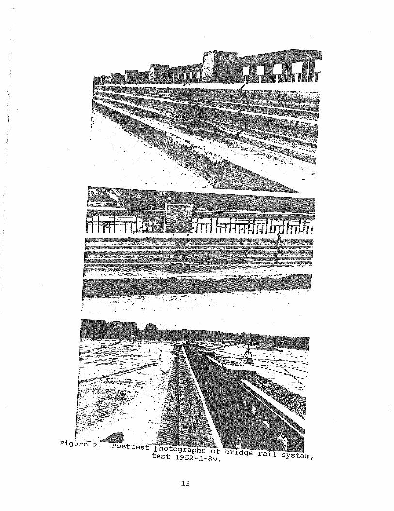
9. Posttest photographs of bridge rail system, test 1952-1-89 .•.••.•.•.•..•..............•....... 15
10. Test site layout, test 1952-2-89 ..•..•.....•..•..• 20
11. Pretest photographs of bridge rail system, test 1952-2-89 ...•..•.....•......•..•..•..•....... 21
12. Pretest photographs of test vehicle, test 1952-2-89 .................................................................... .. 22
13. Test summary, test 1952-2-89 .•..............•....• 23
14. Vehicle acceleration, test 1952-2-89 .•.....••.•... 24
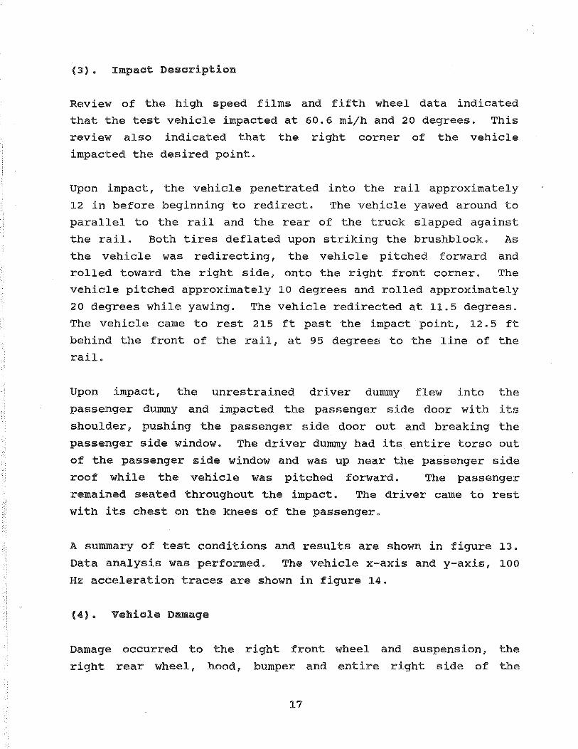
15. Posttest photographs of test vehicle, test 1952-2-89 ..•..•...•..•..•..•.•.•.....•....... 25
16. Posttest photographs of bridge rail system, test 1952-2 .... 89 .. .................................................................... .. 26
17. Test site layout, test 1952-3-89 ................. . 32
18. Pretest photographs of bridge rail system, test 1952-3-89 ..•...•...•..........•..•..•........ 33
ii
LIST OF FIGURES (continued)
Figure
19. Pretest photographs of test vehicle, test 1952-3-89 .....•........•...•................. 34
20. Test summary, test 1952-3-89 ..................... . 35
21. Vehicle acceleration, test 1952-3-89 ............. . 36
22. Posttest photographs of test vehicle, test 1952-3-89 .•.........•........................ 37
23. Posttest photographs of bridge rail system, test 1952-3-89 .•...•....•......................... 38
24. MDOT Open Parapet bridge rail .................... . 44
25. Simulated support structure and bridge rail cantilever .. .......... ~ ...................................................... .. 45
26. Test site layout, test 1952-4-90 ....•.......•..... 46
27. Pretest photographs of bridge rail system, test 1952-4-90 .....•.....••....................... 47
28. Pretest photographs of test vehicle, test 1952-4-90 •..•..........• • ..•...•............• 48
29. Test summary, test 1952-4-90 •........•.•..•...•... 49
30. Posttest photographs of test vehicle, test 1952-4-90 •..•...•..••..•.......•............. 50
31. Posttest photographs of bridge rail system, test 1952-4-90 .. ............ ., ...... ., .............................................. .. 51
32. Test site layout, test 1952-5-90 ................. . 56
33. Pretest photographs of bridge rail system, test 1952-5-90 •...•...••.•••...•...•...••...•..... 57
34. Pretest photographs of test vehicle, test 1952-5-90 ...•..•••...•...•........•......••.. 58
35. Test summary, test 1952-5-90 .••.•••••.•..•..•..... 59
36. Vehicle acceleration, test 1952-5-90 ..•...•..•..•• 60
iii

LIST OF FIGURES (continued)
Figure
37. Posttest photographs of test vehicle, test 1952-5-90 ..........•....•.................... 61
38. Posttest photographs of bridge rail system, test 1952-5-90 ......•............................. 63
39. Test site layout, test 1952-6-90 ................. . 68
40. Pretest photographs of bridge rail system, test 1952-6-90 ................................... . 69
41. Pretest photographs of test vehicle, test 1952-6-90 ...........•........................ 70
42. Test summary, test 1952-6-90 ..................... . 71
43. Vehicle acceleration, test 1952-6-90 ............. . 72
44. Posttest photographs of test vehicle, test 1952-6-90 ..........•...•..................... 73
45. Posttest photographs of bridge rail system, test 1952-6-90 ...•......•.•..•.................... 74
46. Test site layout, test 1952-7-91 ...•....•......... 79
47. Pretest photographs of bridge rail system, test 1952-7-91 ...•.......••........•...•.......... 80
48. Pretest photographs of test vehicle, test 1952-7-91 .. ............... 0 ...... ., ......................................... .. 81
49. Test summary, test 1952-7-91 .........•............ 82
50. Vehicle acceleration, test 1952-7-91 ............. . 83
51. Posttest photographs of test vehicle, test 1952-7-91 •.•....••....•.........•......•..... 84
52. Posttest photographs of bridge rail system, test 1952-7-91 .••...•.....•.....•...............•. 86
iv
LIST OF TABLES
Table Page
1. Vehicle parameters, test 1952-1-89 ..••.••..••...•• 4
2. Vehicle parameters, test 1952-2-89 .•.••..••..••.•. 16
3. Vehicle parameters, test 1952-3-89 •.•......••..... 29
4. Vehicle parameters, test 1952-4-90 .•..•••.•...••.. 40
5. Vehicle parameters, test 1952-5-90 •.••.•••..•....• 52
6. Vehicle parameters, test 1952-6-90 .•.........•.•.. 64
7. Vehicle parameters, test 1952-7-91 ..••.••..••...•• 76
v
:INTRODUCTION
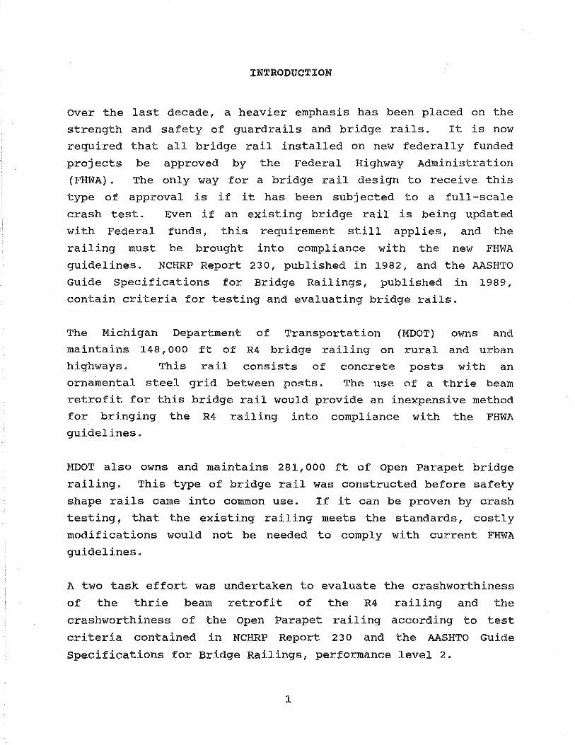
Over the last decade, a heavier emphasis has been placed on the
strength and safety of guardrails and bridge rails. It is now
required that all bridge rail installed on new federally funded
projects be approved by the Federal Highway Administration
(FHWA). The only way for a bridge rail design to receive this
type of approval is if it has been subjected to a full-scale
crash test. Even if an existing bridge rail is being updated
with Federal funds, this requirement still applies, and the
railing must be brought into compliance with the new FHWA
guidelines. NCHRP Report 230, published in 1982, and the AASHTO
Guide Specifications for Bridge Railings, published in 1989,
contain criteria for testing and evaluating bridge rails.
The Michigan Department of Transportation (MDOT) owns and
maintains 148,000 ft of R4 bridge railing on rural and urban
highways. This rail consists of concrete posts with an
ornamental steel grid between posts. The use of a thrie beam
retrofit for this bridge rail would provide an inexpensive method
for bringing the R4 railing into compliance with the FHWA
guidelines.
MDOT also owns and maintains 281, ooo ft of Open Parapet bridge
railing. This type of bridge rail was constructed before safety
shape rails came into common use. If it can be proven by crash
testing, that the existing railing meets the standards, costly
modifications would not be needed to comply with current FHWA
guidelines.
A two task effort was undertaken to evaluate the crashworthiness
of the thrie beam retrofit of the R4 railing and the
crashworthiness of the Open Parapet railing according to test
criteria contained in NCHRP Report 230 and the AASHTO Guide
Specifications for Bridge Railings, performance level 2.
1

TASK A - FULL-SCALE TESTS OF THE R4 RETROFIT BRIDGE RAIL
1. R4 RETROFIT BRIDGE RAIL
The test device was the MDOT R4 Retrofit Bridge Rail. This
bridge rail featured a 68-ft deck, 10-in by 32. 5-in brushblock
the entire length of the rail, seven 12-in by 16-in by 40-in
posts with nominal 6-in by B-in wood blackouts. Six 11-ft, 7.75-
in lengths of 10 gauge thrie beam spanned the area between posts.
This rail was manufactured. No flame cutting of the section or
the holes is allowed. Two 0.875-in bolts connect the thrie beam
through the blocks to the posts. Standard 0. 875-in round flat
washers are used between the rail and the bolt head and special
0.25-in by 3-in square washers are used between the nut and the
post.
posts,
The standard MDOT steel R4
was not removed. The top
railing, mounted between the
of the thrie beam was 34 in
above the deck and the top of the posts were 50 in above the
deck. The entire system was 68 ft long.
This bridge rail system was attached to a rigid, simulated
support structure in order to simulate the effects of a bridge
deck fascia cantilever. A pit was excavated and the bottom
filled with crusher run type soil and compacted to provide a firm
base. A slab was poured on this base as a footer for the
support. An upright wall and an undercut were poured to tie the
support into the previously existing concrete deck. The lateral
deck bars extended from the undercut. The rebar details were
taken from MDOT plans and 40 grade rebar was used throughout the
R4 Retrofit Bridge Rail.
The concrete used was specially formulated to have cured to the
desired strength window (3000 lb/in2 plus 15 percent, minus 0
percent) in 28 days. The deck, brushblock and posts were poured
on July 11, 1989, July 25, 1989 and July 26, 1989, respectively.
The average 28-day breaking strengths were 3335, 3060 and 3418
2

lbjin2 , respectively.
standard cylinders.
brushblock and post
Hammer in situ.
The deck strength was evaluated using
Due to a cylinder quality problem, the
strengths were evaluated using a Schmidt
Figure 1 shows the bridge rail dimensions. Figure 2 shows the
simulated support structure and the bridge rail cantilever.
a. Test 1952-1-89
(1). Test Device
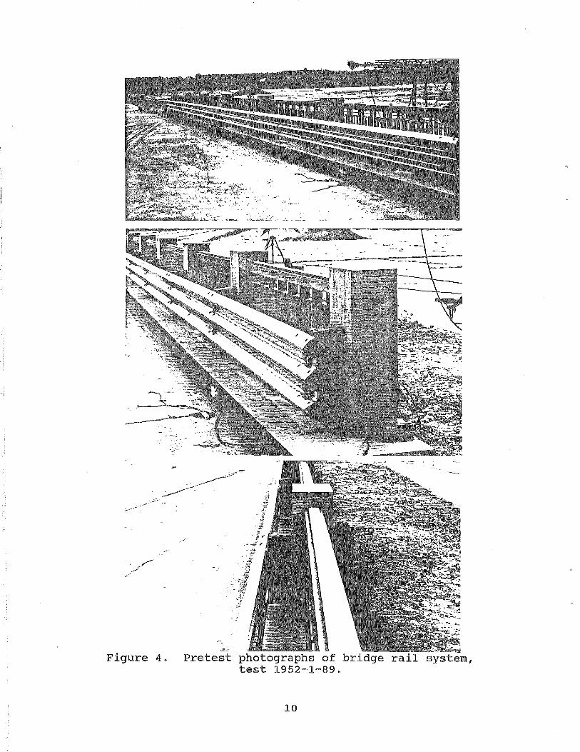
The test device was the MDOT R4 Retrofit Bridge Rail. Figure 3
shows the test site layout.
of the bridge rail system.
(2). Test Vehicle
Figure 4 shows pretest photographs
The test vehicle was a 1982 Honda Civic. The target inertial
vehicle weight was 1800 lb. The vehicle weighed approximately
1750 lb empty. With the instrumentation (no ballast was
required) the inertial weight of the vehicle was 1829 lb. The
target gross vehicle weight was 1950 lb. The gross vehicle
weight was 1972 lb. The inertial weight consists of all weight
items rigidly attached to the vehicle. The gross weight includes
non-attached weight, such as the dummy.
X-, y- and z-axis accelerometers were mounted in the car along
with roll and yaw rate gyros. One uninstrumented dummy was
placed in the vehicle in the driver seat and was unrestrained.
Pretest photographs of the test vehicle are shown in figure 5.
Table 1 lists important parameters of the test vehicle, comparing
the actual parameters with the AASHTO Guide Specifications for
Bridge Railings requirements.
3
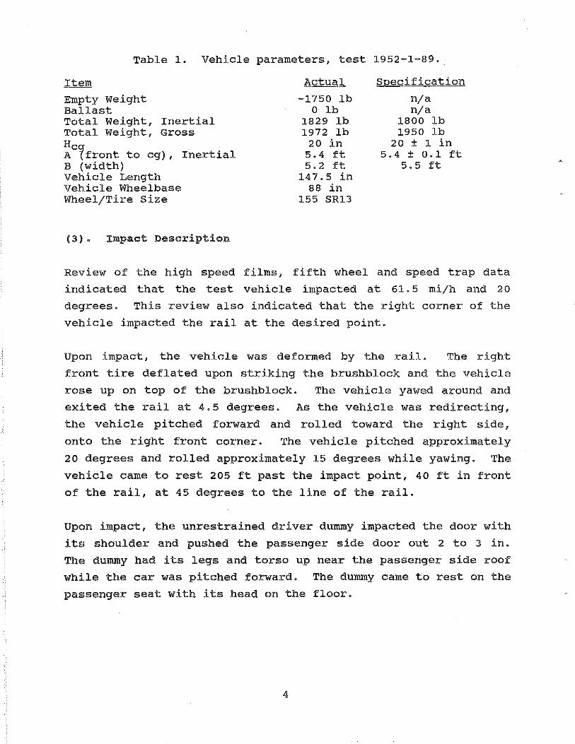
Table 1. Vehicle parameters, test 1952-1-89.
Item
Empty Weight Ballast Total Weight, Inertial Total Weight, Gross Hcg A (front to cg), Inertial B (width) Vehicle Length Vehicle Wheelbase Wheel/Tire Size
(3). Impact Description
Actual
-1750 lb 0 lb
1829 lb 1972 lb
20 in 5.4 ft 5. 2 ft
147.5 in 88 in
155 SR13
Specification
nja nja
1800 lb 1950 lb
20 ± 1 in 5.4 ± 0.1 ft
5.5 ft
Review of the high speed films, fifth wheel and speed trap data
indicated that the test vehicle impacted at 61.5 mijh and 20
degrees. This review also indicated that the right corner of the
vehicle impacted the rail at the desired point.
Upon impact, the vehicle was deformed by the rail. The right
front tire deflated upon striking the brushblock and the vehicle
rose up on top of the brushblock. The vehicle yawed around and
exited the rail at 4.5 degrees. As the vehicle was redirecting,
the vehicle pitched forward and rolled toward the right side,
onto the right front corner. The vehicle pitched approximately
20 degrees and rolled approximately 15 degrees while yawing. The
vehicle came to rest 205 ft past the impact point, 40 ft in front
of the rail, at 45 degrees to the line of the rail.
Upon impact, the unrestrained driver dummy impacted the door with
its shoulder and pushed the passenger side door out 2 to 3 in.
The dummy had its legs and torso up near the passenger side roof
while the car was pitched forward. The dummy came to rest on the
passenger seat with its head on the floor.
4
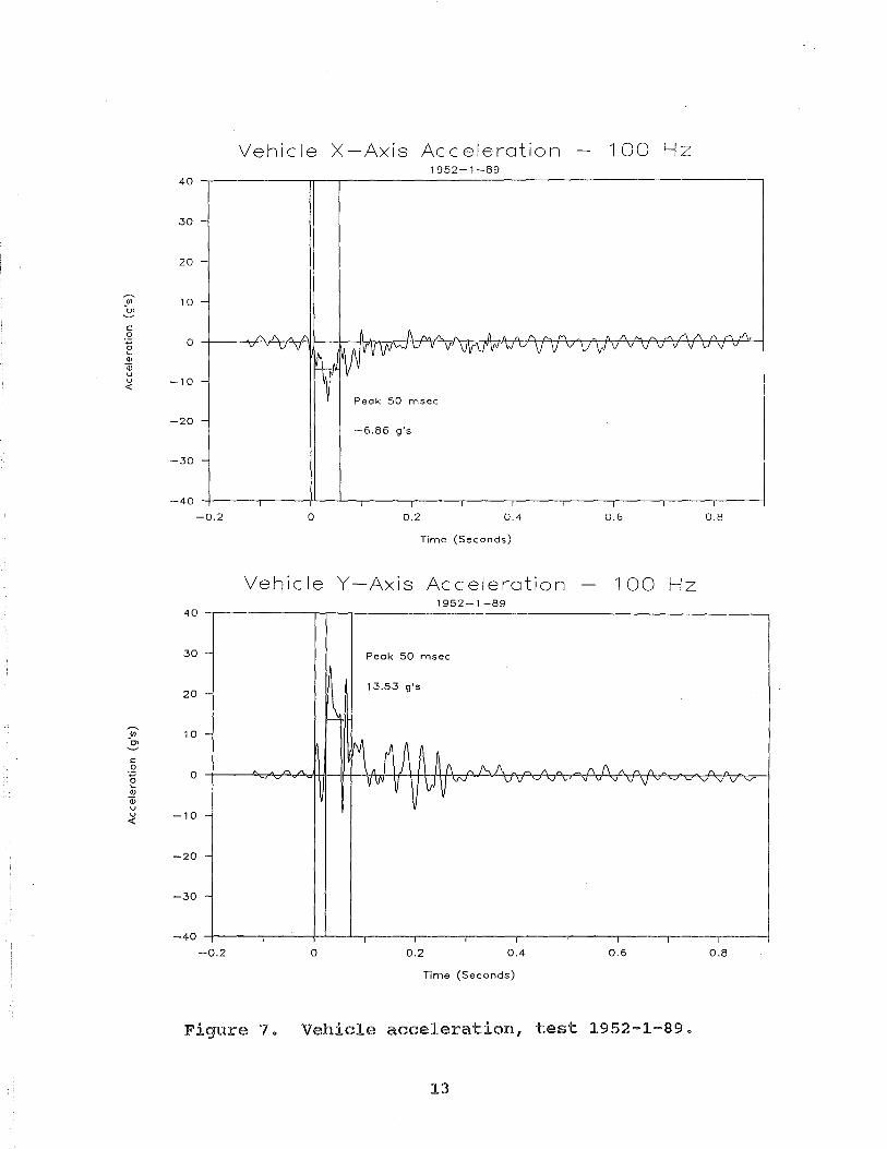
A summary of test conditions and results are shown in figure 6.
Data analysis was performed. The vehicle x-axis and y-axis, 100
Hz acceleration traces are shown in figure 7.
(4). Vehicle Damage
Damage occurred to the right front wheel and suspension, the
right rear wheel, hood, bumper and entire right side of the
vehicle. The passenger side door window was broken and the door
was wedged out 2 to 3 in by the dummy impact. Posttest
photographs of the vehicle are shown in figure 8.
(5). Bridge Rail Damage
The bridge rail suffered very little damage. There were tire
marks on the thrie beam for 101 in starting 5 in past the target
impact line (see subsection c). There was tire scuff on the
brushblock for 161 in starting 13 in prior to the target impact
line. Minor spalling of the brushblock occurred for 106 in
starting 6 in prior to the target impact line. There was no
measurable deflection of the rail.
bridge rail are shown in figure 9.
Posttest photographs of the
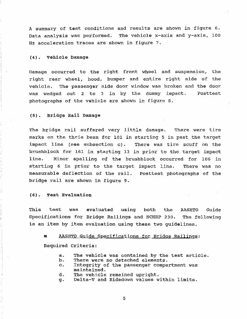
(6). Test Evaluation
This test was AASHTO Guide
Specifications for
is an item by item
evaluated using both the
Bridge Railings and NCHRP 230. The following
evaluation using these two guidelines.
• AASHTO Guide Specifications for Bridge Railings:
Required criteria:
a. The vehicle was contained by the test article. b. There were no detached elements. c. Integrity of the passenger compartment was
maintained. d. The vehicle remained upright. g. Delta-V and Ridedown values within limits.
5
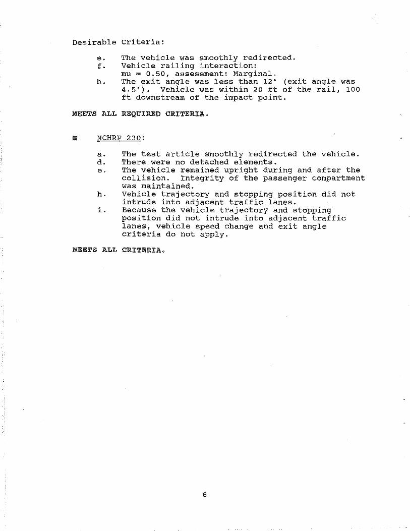
Desirable criteria:
e. The vehicle was smoothly redirected. f. Vehicle railing interaction:
mu = 0.50, assessment: Marginal. h. The exit angle was less than 12" (exit angle was
4.5"). Vehicle was within 20ft of the rail, 100 ft downstream of the impact point.
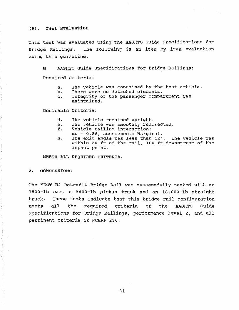
MEETS ALL REQUIRED CRITERIA.
NCHRP 230:
a. The test article smoothly redirected the vehicle. d. There were no detached elements. e. The vehicle remained upright during and after the
collision. Integrity of the passenger compartment was maintained.
h. Vehicle trajectory and stopping position did not intrude into adjacent traffic lanes.
i. Because the vehicle trajectory and stopping position did not intrude into adjacent traffic lanes, vehicle speed change and exit angle criteria do not apply.
MEETS ALL CRITERIA.
6

Overall Length: 68 ft 16 in wide by 12 in
deep post I"' 10ft,7.75in<typ) "'I
=(dt----------lQ.r----------IQ= Plan View
1 0 guage thrie beam Steel R4 Railing
Elevation
Figure 1. MDOT R4 Retrofit bridge rail.
6 in by 8 in wood block (nominal)
6.75 in
Side View

00
Existing Concrete Deck 6-in thickness
ENSCO Simulated Support Structure
MOOT R4 Retrofit Bridge Rail
Figure 2. Simulated support structure and bridge rail cantilever.
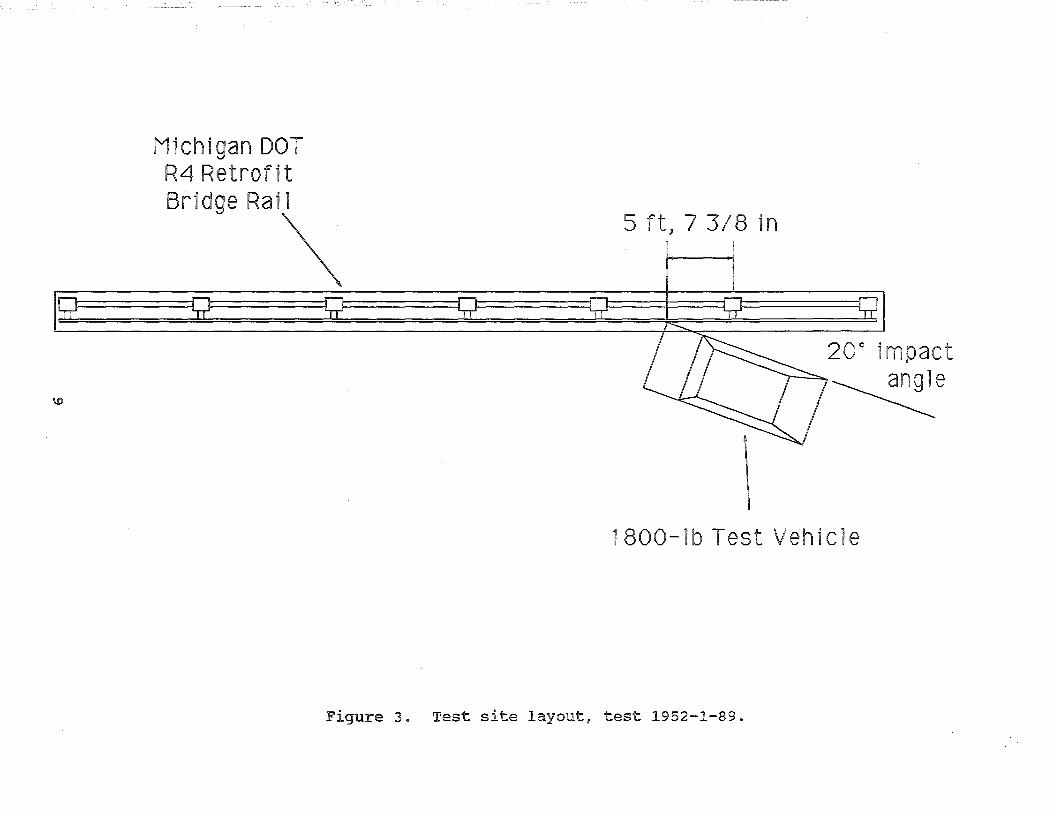
Michigan DOT R4 Retrofit
Bridge Rai\ 5 ft) 7 3/8 in
20° impact
~e
1800-lb Test Vehicle
Figure 3. Test site layout, test 1952-1-89.
. / ... .f
~-
Figure 4. Pretest photographs of bridge rail system, test 1952-1-89.
10
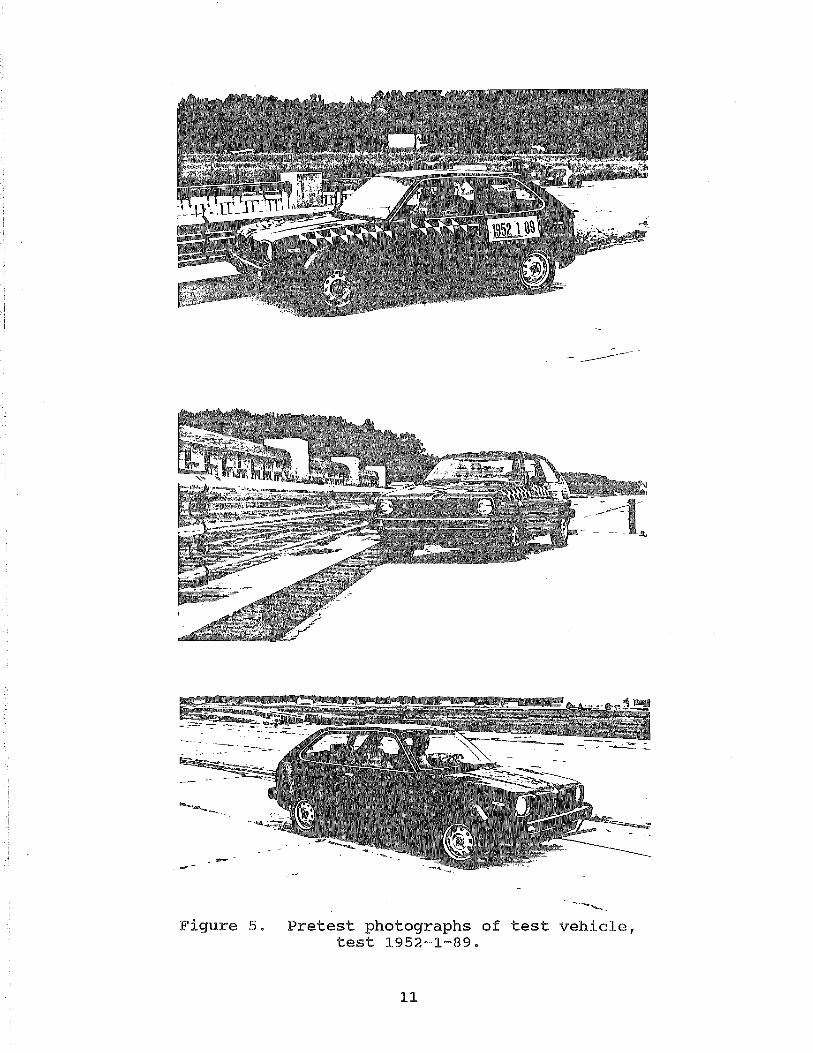
Figure 5. Pretest photographs of test vehicle, test 1952-1-89.
11

I I
40ft
Date: Weather:
Test Vehicle:
Device Configuration:
Vehicle Weight: Planned, Inertial: Actual, Inertial: Planned, Gross: Actual, Gross:
2. Number of Occupants:
3. Occupant Model:
4. Occupant Location:
3. Impact: ~
24 September 1989 Clear, so· F
1982 Honda Civic
Michigan DOT R4 Retrofit Bridge Rail, 68-ft deck, 10-in by 32.5-in brushblock, 12-in by 16-in by 40-in posts, 6-in by S-in wood blockouts, 10 gauge thrie beam, thrie beam 34 in height, posts 50 in height (above deck)
1800 ± 50 lb 1829 lb 1950 ± 50 lb 1972 lb
One
Part 572, 50th percentile male, uninstrumented
Driver Seat, Unrestrained
Planned: 60.0 mi/h Angle lal
20" 20"
Location Midspan posts 2 and 3 Midspan posts 2 and 3 Actual: 61.5 mi;h
Tolerances: Speed: -1.0, +2.5 mijh Angle: -1.0, +2.5 degrees
6. Redirection Angle: 4.5 degrees
7. Redirection Speed: 48.8 mi/h (71.6 ftjs)
e. Total Speed Change: 12.7 mi/h (18.6 ftjs)
9. Total Momentum Change: 1139 lb:...sec
10. Vehicle Damage Index: 01RFEW2 (SAE J224a)
205ft
11. NCHRP 230 Test Number: AASHTO Test Type:
12. NCHRP 230 Impact Severity:
miV sin al2 2
S13 PL2
27.0 kip-ft (Spec: 23 to 29 kip-ft)
NCHRP 230 Design; AASHTO
13. Vehicle Analysis: Observed Limit Values ~
Longitudinal:
Delta-v at 2 ft: -20 Ridedown Acceleration: -3
Lateral:
Delta-v at 1 ft: 25 Ridedown Acceleration: 7
~:
Peak 50 ms acceleration: Longitudinal: Lateral:
ftjs 30/40 ftjs g's 15/20 g's
ftjs 20/30 ftjs g's 15/20 g's
-6.9 g's 13.5 g's
30 ftjs 15 g's
25 ftjs 15 g's
14. Vehicle-Railing Interaction Coefficient of Friction:
mu - Cos theta - VpLY Sin theta
Vp 47.3 mi/h (69.4 !tjs)
15. Test Results Conclusion:
AASHTO Guide Specifications for Bridge Railings:
NCHRP 230:
l!!Y 0.50
assessment Marginal
MEETS ALL REQUIRED CRITERIA.
MEETS ALL CRITERIA.
Figure 6. Test summary, test 1952-1-89.
Vehicle X-Axis Acceleration 100 Hz 1952-1-89
40 -,-----------rr--.-------------------------------------------------~
30
20
10
-10
Peak 50 msec
-20 -5.85 g's
-30
-40 ,_-----,----~--~-------.-----.-----.-----.-----r-----r-----r----~ -0.2 0 0.2 0.4 0.5 0.8
Time (Seconds)
Vehicle Y-Axis Acceleration 100 Hz 1952-1-89
40 ~r----------IT--r---------~----~--------------------------~
30 Peak 50 msec
20 13.53 g's
-10
-20
-30
-40 -r-----.--~-r~~-------.-----.-----.-----.----~----~----~----~ -0.2 0 0.2 0.4 0.5 0.8
Time (Seconds)
Figure 7. Vehicle acceleration, test 1952-1-89.
13
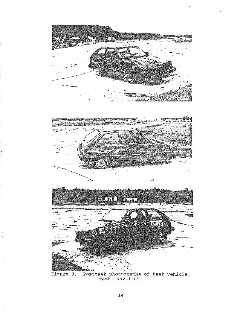
Figure 8. Posttest photographs of test vehicle, test 1952-1-89.
14
test
15

b. Test 1952-2-89
(1). Test Device
The test device was the MDOT R4 Retrofit Bridge Rail. Figure 10
shows the test site layout. Figure 11 shows pretest photographs
of the bridge rail system.
(2). Test Vehicle
The test vehicle was a 1983
inertial vehicle weight was
approximately 4000 lb empty.
Ford F150 pickup. The target
5400 lb. The vehicle weighed
Approximately 1400 lb of ballast
were added. The ballasted inertial weight of the truck was 5411
lb. The gross vehicle weight was 5724 lb.
Two dummies were placed in the vehicle. The driver was
unrestrained while the passenger was restrained. X-, y- and z-
axis accelerometers were mounted in the cab of the truck along
with roll and yaw rate gyros. Pretest photographs of the test
vehicle are shown in figure 12. Table 2 lists important
parameters of the test truck, comparing the actual parameters
with the AASHTO Guide Specifications for Bridge Railings
requirements.
Table 2. Vehicle parameters, test 1952-2-89.
Item
Empty Weight Ballast Total Weight, Inertial Total Weight, Gross Hcg A (front to cg), Inertial B (width) Truck Length Truck Wheelbase Wheel/Tire Size
Actual
-4000 lb -1400 lb 5411 lb 5724 lb
27 in 8.50 ft 6.42 ft 214 in
Truck Box Size 8 ft long by
132.5 in 235 85R15 1.5 ft high
27 in Ground to box floor
16
Specification
nja nja
5400 lb nja
27 ± 1 in 8.5 ± 0.1 ft
6.5 ft
by 5.5 ft wide
(3). Impact Description
Review of the high speed films and fifth wheel data indicated
that the test vehicle impacted at 60.6 mi/h and 20 degrees. This
review also indicated that the right corner of the vehicle
impacted the desired point.
Upon impact, the vehicle penetrated into the rail approximately
12 in before beginning to redirect. The vehicle yawed around to
parallel to the rail and the rear of the truck slapped against
the rail. Both tires deflated upon striking the brushblock. As
the vehicle was redirecting, the vehicle pitched forward and
rolled toward the right side, onto the right front corner. The
vehicle pitched approximately 10 degrees and rolled approximately
20 degrees while yawing. The vehicle redirected at 11.5 degrees.
The vehicle came to rest 215 ft past the impact point, 12.5 ft
behind the front of the rail, at 95 degrees to the line of the
rail.
Upon impact, the unrestrained driver dummy flew into the
passenger dummy and impacted the passenger side door with its
shoulder, pushing the passenger side door out and breaking the
passenger side window. The driver dummy had its entire torso out
of the passenger side window and was up near the passenger side
roof while the vehicle was pitched forward. The passenger
remained seated throughout the impact. The driver came to rest
with its chest on the knees of the passenger.
A summary of test conditions and results are shown in figure 13.
Data analysis was performed. The vehicle x-axis and y-axis, 100
Hz acceleration traces are shown in figure 14.
(4). Vehicle Damage
Damage occurred to the right front wheel and suspension, the
right rear wheel, hood, bumper and entire right side of the
17

vehicle. The passenger side door window
was wedged out by the dummy impact.
vehicle to bend toward the driver side.
was broken and the door
The impact caused the
The front of the truck
was pushed 17 in out of line. Posttest photographs of the truck
are shown in figure 15.
(5). Bridge Rail Damage
The bridge rail suffered major structural damage during this
impact. Posts 3 and 4 were pushed back approximately 8 and 4 in,
respectively, at the top of the post. Damage to the brushblock
and deck occurred at post 3 and damage occurred to the brushblock
at post 4. In both cases, the damage pattern was semicircular
around the post.
The damage at post 3 consisted of cracking in the brushblock and
deck. The brushblock was damaged 30 in before and 35 in past the
post. The deck suffered damage 30 in before and 6 in after the
post. The deck was cracked for 6 in back under the edge.
The damage at post 4 was less severe and only occurred in the
brushblock and the post. The brushblock was damaged 18 in before
and after the post.
of the post to 32
brushblock.
Another crack ran from the upstream corner
in before the post on the edge of the
Spalling occurred to the top portions of posts 3 and 4 above the
top of the guardrail. The maximum permanent guardrail deflection
occurred 8 ft past post 2 and was 7.5 in.
This damage was repaired in preparation for the next test. When
the damaged areas were removed, it was discovered that post 2
also had hairline cracks near the base of the post and was also
removed.
Posttest photographs of the bridge rail are shown in figure 16.
18

(6). Test Evaluation
This test was evaluated
Bridge Railings. The
using this guideline.
using the AASHTO Guide Specifications for
following is an item by item evaluation
~ AASHTO Guide Specifications for Bridge Railings:
Required criteria:
a. The vehicle was contained by the test article. b. There were no detached elements. c. Integrity of the passenger compartment was
maintained. d. The vehicle remained upright.
Desirable Criteria:
e. The vehicle was smoothly redirected. f. Vehicle railing interaction:
mu = 0.73, assessment: Marginal. g. Delta-v and Ridedown values within limits. h. The exit angle was less than 12·. The vehicle was
within 20 ft of the rail, 100 ft downstream of the impact point.
MEETS ALL REQUIRED CRITERIA.
19

N 0
Michigan DOT R4 Retrofit
Bridge Rai\ 5ft,73/8in
5400-lb Test Vehicle
Figure 10. Test site layout, test 1952-2-89.
20° impact angle
-------

Figure 11. Pretest photographs of bridge rail system, test 1952-2-89.
21

- ..
Figure 12. Pretest photographs of test vehicle, test 1952-2-89.
22

N w
r---------------------------zlsrt--------------------------------~
12.5 ft
Date: Weather:
Test Vehicle:
Device Configuration:
1. Vehicle Weight: Planned, Inertial: Actual, Inertial: Actual, Gross:
'· Number of Occupants:
'· Occupant Model:
•• Occupant Locations:
'· I111pact: """-"'!
24 September 1989 Clear, 80' F
1983 Ford FlSO Pickup
Michigan DOT R4 Retrofit Bridge Rail, 68-!t deck, 10-in by 32.5-in brushblock, 12-in by 16-in by 40-in posts, 6-in by a-in wood blackouts, 10 gauge thr!e beam, thrie beam 34 in height, posts 50 in height (above deck)
5400 lb 5411 lb 5724 lb
Two
Part 572, so percentile male
Driver Seat, Unrestrained Passenger Seat, Restrained
Planned: 60.0 mi;h l\m!lo_
20' 20.
Loolli2n Midspan poets 2 and 3 Midspan posts 2 and 3 Actual: 60.6 mi/h
Tolerances: Speed: Angle:
6. Redirection Angle:
7. Redirection Speed:
•• Total Speed Change:
9. Total Momentum Change:
10. Vehicle Damage Index: (SAE J224a)
-1.0, +2.5 mijh -1.0, +2.5.degrees
11.5 degrees
39.1 mi;h (57.4 ftja)
21.5 mi/h (31.5 ft/s)
5600 lb..:..sec
OlRFEW2
I Ill
11. AASHTO Test Type:
12. Vehicle Analysis:
NCHRP 230:
Longitudinal:
Delta-V at 2 ft: Ridedown Acceleration:
Lateral:
Delta-v at 1 ft: Ridedown Acceleration:
Peak 50 me acceleration: Longitudinal: Lateral:
PL2
-23 ft;s -10 g's
19 ft/s 12 g's
-7.7 g's 11.1 g's
AASHTO Limlli
30 ft/s 15 g•s
25 ft;s 15 g's
13. Vehicle-Railing Interaction Coefficient of Friction:
mu cos theta - VpLY Sin theta
Vp = 41.9 mi/h {61.4 ftjs)
14. Test Results Conclusion:
AASHTO Guide Specifications for Bridge Railings:
"" 0.73 assessment
Marginal
MEETS ~LL REQUIRED CRITERIA,
Figure 13. Test summary, test 1952-2-89.

Vehicle X-Axis Acceleration 100 Hz 1952-2-89
50
40
30
20 ~
m :,_,; c 10 I ~ 2 ID 0 o; u u <(
-10
A A IL " A
.~ A JIJVVVV v v v
vv
-
Peak 50 msec
-20 -' -7.67 g's
-30 _j
-40 -, ' -0.2 0 0.2 0.4 0.6 0.8
T1me (Seconds)
Vehicle Y-Axis Acceleration 100 Hz 1952-2-89
50
40
30 Peak 50 msec
20 ~
11.11 g's m
:,_,; c 10 0
"' 2 • 0 o; u
-
~/LA lA 1\ ""
lrl 'f \f/'VJ ~
u <(
-10 -
-20 -
-30 -
-40 ' -0.2 0 0.2 0.4 0.6 0.8
Time (Seconds)
Figure 14. Vehicle acceleration, test 1952-2-89.
24
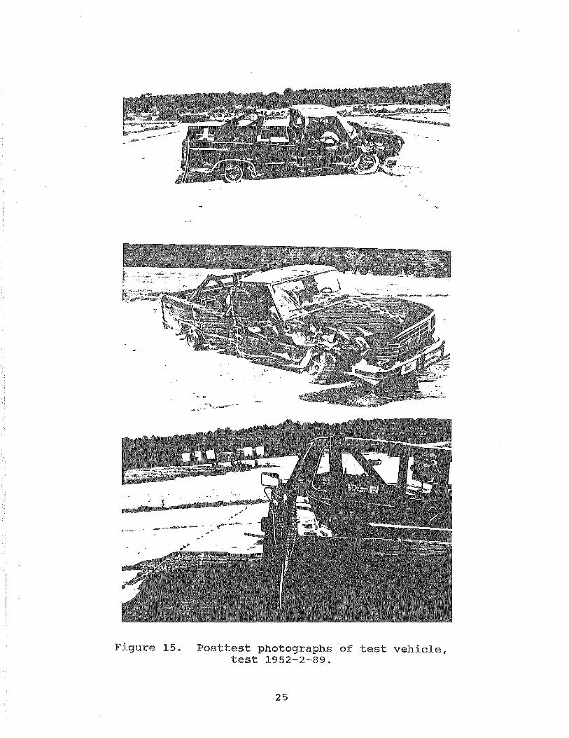
Figure 15. Posttest photographs of test vehicle, test 1952-2-89.
25

Figure 16. Posttest photographs of bridge rail system, test 1952-2-89.
26
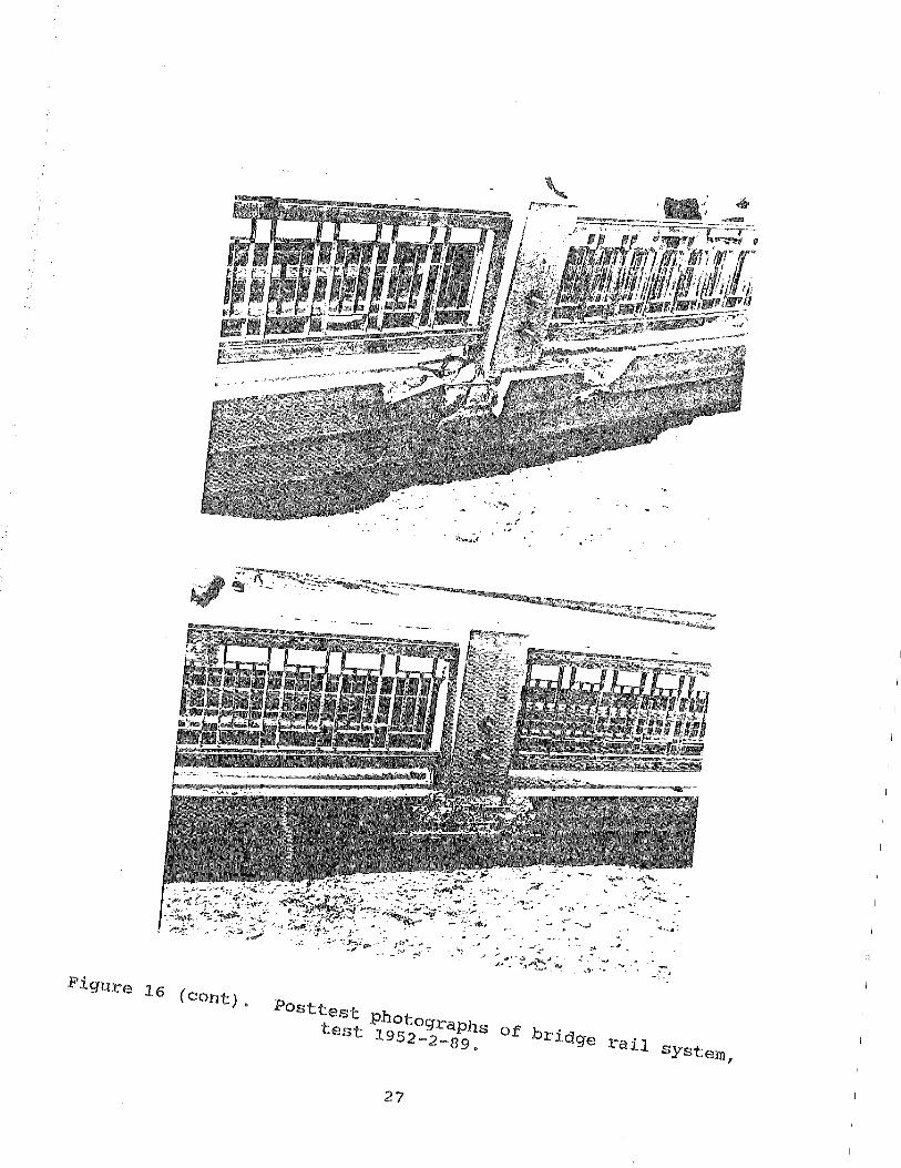
Figure 16 (cont).
Posttest Photographs of bridge rail system, test 1952-2-89.
27

c. Test 1952-3-89 '
(1). Test Device
The test device was the MOOT R4 Retrofit Bridge Rail.
This bridge rail was also used in tests 1952-1-89 and 1952-2-89.
There was considerable damage to the bridge rail after test 2.
Posts 2, 3 and 4 were removed and replaced. A 6-ft length and a
5-ft length of the brushblock were removed and .repaired around
posts 3 and 4, respectively. A 3-ft and a 1-ft length of deck
were removed and repaired around posts 3 and 4, respectively.
The concrete repair work took place in September 1989. The deck,
brushblock and posts were poured on September 12, September 12
and September 13, respectively. Because the post strength in
this design is critical to transmit almost all of the impact load
to the deck, the test was conducted when the post strength was
within the required window (3000 lbjin2 plus 15 percent, minus o percent). On the test date, the cylinder breaking strength for
the posts was 3104 lbjin2 . The cylinder breaking strength for
the deck and brushblock was 4014 lbjin2 .
Figure 17 shows the test site layout.
photographs of the bridge rail,system.
(2). Test Vehicle
Figure 18 shows pretest
The test vehicle was a 1973 International Loadstar 1600. The
target vehicle weight was
approximately 11300 lb empty.
18000 lb. The vehicle weighed
Approximately 6700 lb of straw and
sand ballast were added.
18000 lb.
The ballasted weight of the truck was
X-, y- and z-axis accelerometers were mounted in the cab of the
truck along with roll and yaw rate gyros. Pretest photographs of
the test vehicle are shown in figure 19. Table 3 lists important
28

parameters of the
with the AASHTO
requirements.
test truck, comparing the
Guide Specifications for
actual parameters
Bridge Railings
Table 3. Vehicle parameters, test 1952-3-89.
Item
Empty Weight Ballast Total Weight Hcg A (front to cg) B (width) Truck Length Truck Wheelbase Wheel/Tire Size Truck Box Size 20 ft long Ground to top of box
(3). Impact Description
Actual
-11300 lb -6700 lb 18000 lb 49.2 in 12.8 ft 7.5 ft
29 ft, 6 in 18 ft, 1 in
11R22.5
Specification
nja nja
18000 lb 49 ± 1 in
12.8 ± 0.2 ft 7.5 ft
by 8 ft high by 11 ft, 11 in
7.5 ft wide
Review of the high speed films and speed trap data indicated that
the test vehicle impacted at a speed of 49.0 mijh and an angle of
15 degrees. This review also indicated that the right corner of
the vehicle impacted the rail 6 in downstream of the desired
impact point.
Upon impact, the vehicle penetrated into the rail approximately 5
in. The truck rolled toward the rail approximately 20 degrees
and pitched forward approximately 20 degrees. The rear wheels
left the ground while the truck was pitching. The vehicle rolled
back to upright and was redirected at 3 degrees. The vehicle
came to rest 165 ft downstream of impact, in line with the rail.
Debris was found between the rail and the steel fence from the
point impact
damaged.
torn open
to the end of the rail. Four blackouts were
Also the passenger side, bottom corner of the box was
from the contact with the rail. From this, it is
possible to suppose that the box of the truck was locked under
the back side of the top of the thrie beam. The passenger side,
29

bottom corner of the box impacted post 4, which also caused some
of the damage.
A summary of test conditions and results are shown in figure 20.
Data analysis was performed. The vehicle x-axis and y-axis, 100
Hz acceleration traces are shown in figure 21.
(4). Vehicle Damage
The chassis at the front of the truck was damaged and twisted.
The hood came open and the front axle was torn from the frame and
pushed under the truck. However, the occupant compartment was
not intruded. The rail side of the vehicle was damaged from
impacting the rail, posts and blackouts during the impact event.
A 4-ft by 4-ft hole was torn in the impact side corner of the box
of the truck. Minor truck parts, ballast and debris were wedged
between the posts, blackouts and rail. All tires on the impact
side were deflated from contact with the brushblock and the
wheels were damaged. Posttest photographs of the truck are shown
in figure 22.
(5). Bridge Rail Damage
The bridge rail was damaged from the impact point downstream 45
ft. Four blackouts were damaged from impacts with the truck box.
Posts 3 and 4 were damaged and showed cracks. Post 3 was cracked
around the bottom and in a cone extending to the back of the
brushblock. Post 4 was cracked around the bottom and through the
post in two
brushblock.
other places. The cracks did not extend into the
Post 4 also was spalled at the top from the impact
with the truck box. The deck was not damaged. The maximum
permanent thrie beam rail deflection was 3 in. Posttest
photographs of the bridge rail are shown in figure 23.
30
(6). Test Evaluation
This test was evaluated
Bridge Railings. The
using this guideline.
using the AASHTO Guide Specifications for
following is an item by item evaluation
m AASHTO Guide Specifications for Bridge Railings:
Required criteria:
a. The vehicle was contained by the test article. b. There were no detached elements. c. Integrity of the passenger compartment was
maintained.
Desirable Criteria:
d. The vehicle remained upright. e. The vehicle was smoothly redirected. f. Vehicle railing interaction:
mu = 0.86, assessment: Marginal. h. The exit angle was less than 12·. The vehicle was
within 20 ft of the rail, 100 ft downstream of the impact point.
MEETS ALL REQUIRED CRITERIA.
::! • CONCLUSIONS
The MDOT R4 Retrofit Bridge Rail was successfully tested with an
1800-lb car, a 5400-lb pickup truck and an 18, 000-lb straight
truck. These tests indicate that this bridge rail configuration
meets all the required criteria of the AASHTO Guide
Specifications for Bridge Railings, performance level 2, and all
pertinent criteria of NCHRP 230.
31
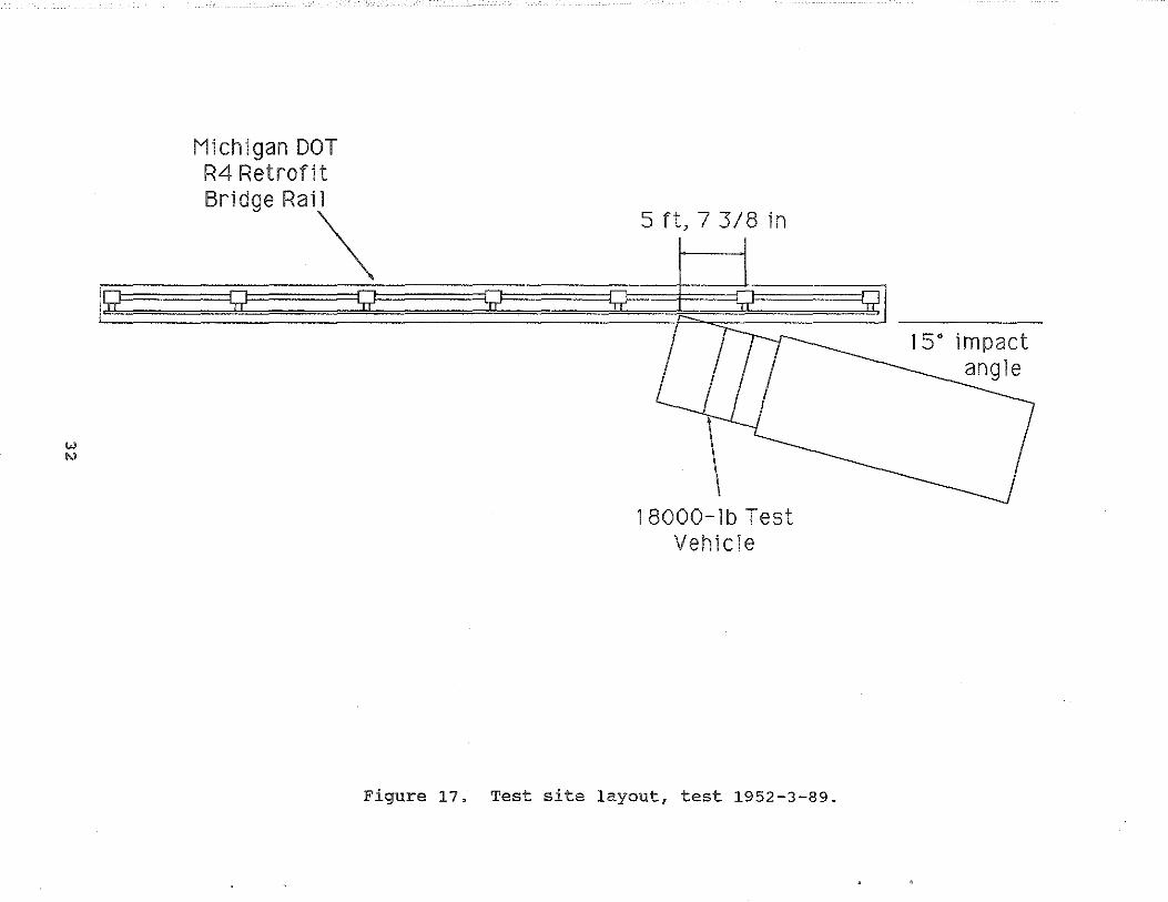
Michigan DOT R4 Retrofit
Bridge Rai\ 5 ft, 7 3/8 in
18000-lb Test Vehicle
Figure 17. Test site layout, test 1952-3-89.

Figure 18. Pretest photographs of bridge rail system, test 1952-3-89.
33

~---~--~=~- ~~ Figure 19. Pretest photographs of test vehicle,
test 1952-3-89.
34

165ft
Date: Weather:
Teat Vehicle:
Device Configuration:
1.
'· '. '·
Vehicle Weight: Planned, Inertial: Actual, Inertial:
Number of Occupants:
Occupant Model:
Occupant Locations:
11 October 1989 Clear, 60" F
1973 International Loadstar 1600
Michigan DOT R4 Retrofit Bridge Rail, 68-ft deck, lO-in by 32.5-in brushblock, 12-in by 16-in by 40-in posts, 6-in by a-in wood blackouts, 10 gauge thrie beam, thrie beam 34 in height, posts 50 in height (above deck)
18,000 lb 18,000 lb
None
n;a
nja
s. Impact: Planned: Actual:
~ 50.0 mi/h 49.0 mi;h
~ 15" 15"
Location Midspan posts 2 and Midspan posts 2 and
•• 7.
•• 9.
Tolerances: Speed: Angle:
Redirection Angle:
Redirection Speed:
Total Speed Change:
Total Momentum Change:
10. Vehicle Damage Index: (SAE J224a)
-1.0, +2.5 mi/h -1.0, +2.5 degrees
3 degrees
23.4 mi/h (J4.4 i'tjs)
25.6 mi/h (J7.5 ft/s)
20,963 lb-sec
n;a
11. AASHTO Test Type:
12. Vehicle Analysis:
NCHRP 230:
Longitudinal:
Delta-v at 2 ft: Ridedown Acceleration:
Lateral:
Oelta-v at 1 ft: Ridedown Acceleration:
Peak 50 ~s acceleration: Longitudinal: Lateral:
PL2
-16 ft;s -7 g's
13 ft/s 3 g's
-9.8 g's 3.8 g's
AASHTO Limits
30 ft/s 15 g's
25 ftjs 15 g•s
13. Vehicle-Railing Interaction Coefficient of Friction:
Vp a 36.4 mi/h (53.4 ftjs)
14. Test Results Conclusion:
AASHTO Guide Specifications for Bridge Railings:
"" 0.86
MEETS ALL REQUIRED CRITERIA.
Figure 20. Test summary, test 1952-3-89.

Vehicle X-Axis Ace eleration 100 Hz 1952-3-89
40
30 I 20 - w 10
w :s 0
c 0
"' -10
(\ fl. A A ~
\) v 'rJVVyv ~ "'V\r\f v -vv- v~
-2 • Peak 50 msec o;
-20 u u
-9.77 g's <{
-30
-40
-50 -
-50
-0.2 0 0.2 0.4 0.6 0.8
Time (Seconds)
Vehicle Y-Axis Acceleration 100 Hz 1952-3-89
40
30
20
Peak 50 msec 10
~
w :s 0 r1\ ~ 3.77 g's
1\/1. ~. "' ~ ~
' ~ w c 0
" -10 2
-• o;
-20 u -u <{
-30
-40 -
-50 -
-50
-0.2 0 0.2 0.4 0.6 0.8
Time (Seconds)
Figure 21. Vehicle acceleration, test 1952-3-89.
36

Figure 22.
It- •. ~-·
Posttest photographs of test vehicle, test 1952-3-89.
37

I Figure 23.
... . . '
Posttest photographs of bridge rail system, test 1952-3-89.
38