RP Watkins “OneLedge” connector Allowable downward loads ... · For applications on projects...
24
Technical Report Technical Report Technical Report Technical Report 415-329-6100 maffei-structure.com San Francisco :: Oakland RP Watkins “OneLedge” connector Allowable downward loads from experimental testing To: Michael Summers, RP Watkins Prepared by: Karl Telleen and Joe Maffei, Maffei Structural Engineering 9 February 2018 Scope This report provides allowable loads for vertical (downward) load bearing capacity of the RP Watkins OneLedge connector in accordance with the experimental testing standard ASTM D7147-11 “Standard Specification for Testing and Establishing Allowable Loads for Joist Hangers,” which is referenced by the 2015 International Building Code. Maffei Structural Engineering provided recommendations for testing in a report dated 14 July 2017. RP Watkins fabricated test specimens. Applied Materials Engineering (AME) carried out testing as described in the testing report dated 6 February 2018 (attached herein as Appendix 1). Description of the OneLedge connector The OneLedge connector by RP Watkins, is a product for attaching a wooden ledger board to an Insulated Concrete Form (ICF) structural wall. The ledger board runs parallel to the length of the wall. Joists then attach to the ledger board perpendicularly, using a separate connection. The OneLedge consists of a single piece of cold-formed galvanized steel. It comes in a range of widths to accommodate the width of the ledger board. Before the wall concrete is placed, the vertical tabs of the OneLedge are inserted through cut slits in the ICF form such that they penetrate through the insulation and into the concrete. One reinforcing bar is placed horizontally through the holes in the tabs, and one bar is placed vertically, between the tabs. After the concrete wall is cast and cured, the ledger board is installed, bearing on the OneLedge connector’s seat. The ledger board is fastened to the OneLedge using screws that penetrate through the front face of the OneLedge, through the ledger board, and through the back face of the OneLedge, such that the tips of the screws are in the wall ICF form.
Transcript of RP Watkins “OneLedge” connector Allowable downward loads ... · For applications on projects...

Technical ReportTechnical ReportTechnical ReportTechnical Report
415-329-6100
maffei-structure.com
San Francisco :: Oakland
RP Watkins “OneLedge” connector
Allowable downward loads from experimental testing
To: Michael Summers, RP Watkins
Prepared by: Karl Telleen and Joe Maffei, Maffei Structural Engineering
9 February 2018
Scope
This report provides allowable loads for vertical (downward) load bearing capacity of the RP
Watkins OneLedge connector in accordance with the experimental testing standard ASTM
D7147-11 “Standard Specification for Testing and Establishing Allowable Loads for Joist Hangers,”
which is referenced by the 2015 International Building Code.
Maffei Structural Engineering provided recommendations for testing in a report dated 14 July 2017.
RP Watkins fabricated test specimens. Applied Materials Engineering (AME) carried out testing as
described in the testing report dated 6 February 2018 (attached herein as Appendix 1).
Description of the OneLedge connector
The OneLedge connector by RP Watkins, is a product for attaching a wooden ledger board to an
Insulated Concrete Form (ICF) structural wall. The ledger board runs parallel to the length of the
wall. Joists then attach to the ledger board perpendicularly, using a separate connection.
The OneLedge consists of a single piece of cold-formed galvanized steel. It comes in a range of
widths to accommodate the width of the ledger board.
Before the wall concrete is placed, the vertical tabs of the OneLedge are inserted through cut slits in
the ICF form such that they penetrate through the insulation and into the concrete. One reinforcing
bar is placed horizontally through the holes in the tabs, and one bar is placed vertically, between
the tabs. After the concrete wall is cast and cured, the ledger board is installed, bearing on the
OneLedge connector’s seat. The ledger board is fastened to the OneLedge using screws that
penetrate through the front face of the OneLedge, through the ledger board, and through the back
face of the OneLedge, such that the tips of the screws are in the wall ICF form.

RP Watkins OneLedge connector Allowable downward loads from experimental testing
9 February 2018
Summary of test results and allowable load
Table 1 summarizes key results from experimental testing and the resulting allowable load for
design. This summary is based on the detailed test results shown in Appendix 1.
In accordance with ASTM D7147-11 Section 13, the allowable downward load is calculated as the
lesser of:
(a) The lowest ultimate load per OneLedge connector divided by 3.
(b) The average, over each OneLedge connector in each specimen, load that produces a vertical
deflection of 0.125 inches at the bottom of the OneLedge connector with respect to the wall.
The ultimate load measured in the test was limited by the strength of the wood joists.
Table 1 Summary of test results and allowable load
specimen ultimate load
per OneLedge (lbs)
load per OneLedge at 0.125” deflection (lbs) allowable load per
OneLedge (lbs) OneLedge 1 OneLedge 2
1 8191 2991 3292
2 8990 4083 4274
3 8675 4256 3975
Minimum / 3 = 2730 Average = 3812 Allowable = 2730
Applicability of allowable load
Figure 1, Figure 2, and Figure 3 show the configuration and dimensions of the tested specimens.
The allowable load specified above is applicable to OneLedge connectors having the configuration
shown in Figure 2. Project parameters are permitted to vary within the ranges stated in Table 2.
Adjustments to allowable load
For applications on projects where the project specified concrete strength (f’c, specified) for the ICF
wall is less than 91% of the tested concrete strength (f’c, tested) stated in Table 2, the allowable load
stated above shall be reduced in accordance with ASTM D7147-11 Section 13.5.9 by multiplying by:
√(f’c, specified/ f’c, tested) ≤ 1.0
For applications on projects where the project specified thickness (tspec) and/or tensile strength
(Fu_spec) for the OneLedge sheet metal material is less than the tested OneLedge sheet metal
thickness (ttested) and/or tensile strength (Fu_tested) stated in Table 2, the allowable load stated above
shall be reduced in accordance with ASTM D7147-11 Section 13.5.7 by multiplying by:
(3.0/2.5)(Fu_spec/Fu_tested) (tspec/ttested) ≤ 1.0
RP Watkins OneLedge connector Allowable downward loads from experimental testing
9 February 2018
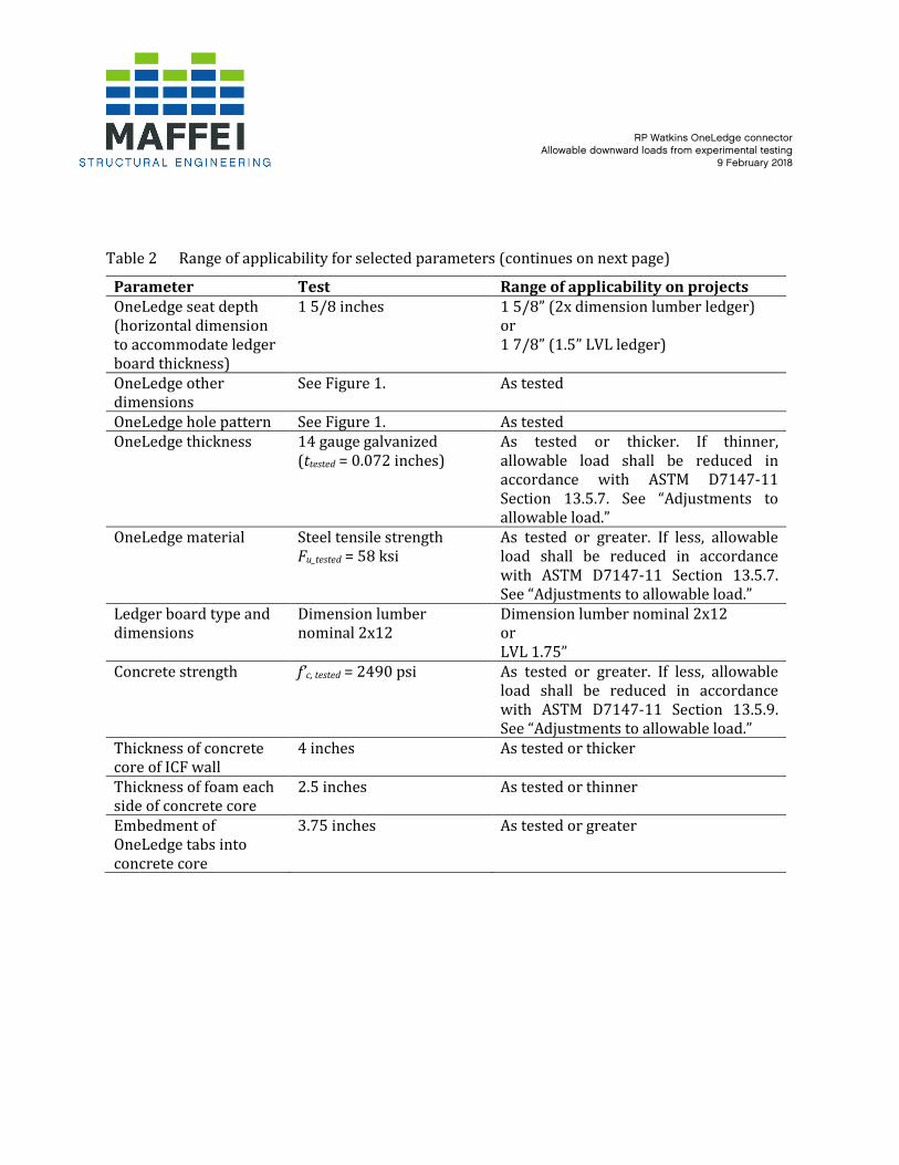
Table 2 Range of applicability for selected parameters (continues on next page)
Parameter Test Range of applicability on projects
OneLedge seat depth
(horizontal dimension
to accommodate ledger
board thickness)
1 5/8 inches 1 5/8” (2x dimension lumber ledger)
or
1 7/8” (1.5” LVL ledger)
OneLedge other
dimensions
See Figure 1. As tested
OneLedge hole pattern See Figure 1. As tested
OneLedge thickness 14 gauge galvanized
(ttested = 0.072 inches)
As tested or thicker. If thinner,
allowable load shall be reduced in
accordance with ASTM D7147-11
Section 13.5.7. See “Adjustments to
allowable load.”
OneLedge material Steel tensile strength
Fu_tested = 58 ksi
As tested or greater. If less, allowable
load shall be reduced in accordance
with ASTM D7147-11 Section 13.5.7.
See “Adjustments to allowable load.”
Ledger board type and
dimensions
Dimension lumber
nominal 2x12
Dimension lumber nominal 2x12
or
LVL 1.75”
Concrete strength f’c, tested = 2490 psi As tested or greater. If less, allowable
load shall be reduced in accordance
with ASTM D7147-11 Section 13.5.9.
See “Adjustments to allowable load.”
Thickness of concrete
core of ICF wall
4 inches As tested or thicker
Thickness of foam each
side of concrete core
2.5 inches As tested or thinner
Embedment of
OneLedge tabs into
concrete core
3.75 inches As tested or greater

RP Watkins OneLedge connector Allowable downward loads from experimental testing
9 February 2018
Parameter Test Range of applicability on projects
Steel reinforcing bars
added in concrete wall
at OneLedge (in
addition to typical wall
reinforcement)
1 bar horizontal.
#3 18 inches long.
1 bar vertical.
#3 18 inches long.
As tested or greater.
Horizontal bar must be placed in holes
in OneLedge as shown in Figure 2.
Bar must be centered on OneLedge.
Vertical bar must pass between
OneLedge tabs and must be adjacent to
the horizontal bar, between the
horizontal bar and the OneLedge.
Horizontal edge
distance
10 inches As tested or greater (from centerline of
OneLedge to end of ICF concrete wall or
opening)
Fasteners of OneLedge
to ledger board
6 screws, #12 diameter,
2 1/2” long:
ITW Buildex “Teks 3 HWH
CL 12-14 x 2-1/2”
As tested or greater
Figure 1 OneLedge connector dimensions. Dimensions are not shown here for (a) horizontal
length of tabs and for (b) depth of seat (horizontal dimension to accommodate ledger
board thickness) because these dimensions vary for different versions of the product.
See Table 2 for ranges of applicability of testing. (Image from www.watkinshanger.com)

RP Watkins OneLedge connector Allowable downward loads from experimental testing
9 February 2018
Figure 2 Tested specimen dimensions (drawing by RP Watkins).

RP Watkins OneLedge connector Allowable downward loads from experimental testing
9 February 2018
Figure 3 Test setup. Joist length is 24 inches.

RP Watkins OneLedge connector Allowable downward loads from experimental testing
9 February 2018
Appendix 1: Testing report

Page 1 of 17
February 6, 2018
Mr. Michael Summers Project Number 1170972C
RP Watkins LLC
13401 S 226th Street
Gretna, NE 68028
Subject: RP Watkins OneLedge Load Testing
Dear Mr. Summers:
As requested, Applied Materials & Engineering, Inc. (AME) has completed load testing the RP Watkins
OneLedge. The intent of the testing was to determine the vertical downward load capacity of the RP
Watkins OneLedge attached to mockup ICF walls.
SAMPLE DESCRIPTION
Three mockup samples were received on November 13, 2017. Mockup configuration consisted of two
20"x24"x9" thick ICF walls. Two wood I-joists spanning 24" in length were fastened with joist hangers
to a single wooden ledger board at each end of the joists. The ledger board was seated in and fastened
with screws to the RP Watkins OneLedge, which had been cast into the ICF walls. Specimen details are
based on the test protocol from Maffei Structural Engineering dated July 14, 2017. Material test results
for the materials used to construct the specimens are provided in Appendix A.
TEST PROCEDURE
Three samples were tested on November 27 and 28, 2017 using a calibrated universal testing machine.
Samples were tested in general accordance with applicable procedures outlined in ASTM D7147-11,
“Standard Specifications for Testing and Establishing Allowable Loads of Joist Hangers”, ASTM
International. Samples were tested when (ICF) concrete reached an average compressive strength of
2490 psi (see Appendix B). A vertical compressive load was applied to the center of the web stiffened I-
joist via a steel load transfer block at a constant rate of axial deformation of 0.1 in. /min. without shock
until the specimen could not support any further loading and load-deflection curve showed that the
vertical load resistance was no longer increasing with increased deflection.
A pre-load of 1000 lbf was applied before uniform loading began. Deflection of each OneLedge was
continuously using a calibrated LVDT. Test setup is provided in Appendix C.


Page 3 of 17
TABLE I
ASTM D7147-11
RP WATKINS ONELEDGE LOAD TESTING
PROJECT NUMER 1170972C
Test # 1 2 3 Average of 3
Tests
Load at 0.125" Deflection of
Right Hanger, lbf 5982 8166 8512 ..
Load at 0.125” Deflection of
Left Hanger, lbf 6584 8547 7950 ..
Average Hanger Load at
0.125" Deflection, lbf 6283 8357 8231 7624
Maximum Load at Failure,
lbf 16382 17979 17350 17237
Specific Gravity of Right
Ledger 0.398 0.328 .369 ..
Specific Gravity of Left
Ledger 0.354 0.362 .387 ..
Moisture Content of Right
Ledger Board, % 10.1 10.0 10.6 ..
Moisture Content of Left
Ledger Board, % 10.3 9.8 9.9 ..

Page 4 of 17
FIGURE 1
ASTM D7147
RP WATKINS ONELEDGE LOAD TESTING – TEST #1
PROJECT NUMER 1170972C

Page 5 of 17
FIGURE 2
ASTM D7147
RP WATKINS ONELEDGE LOAD TESTING – TEST #2
PROJECT NUMER 1170972C

Page 6 of 17
FIGURE 3
ASTM D7147
RP WATKINS ONELEDGE LOAD TESTING – TEST #3
PROJECT NUMER 1170972C

Page 7 of 17
APPENDIX A
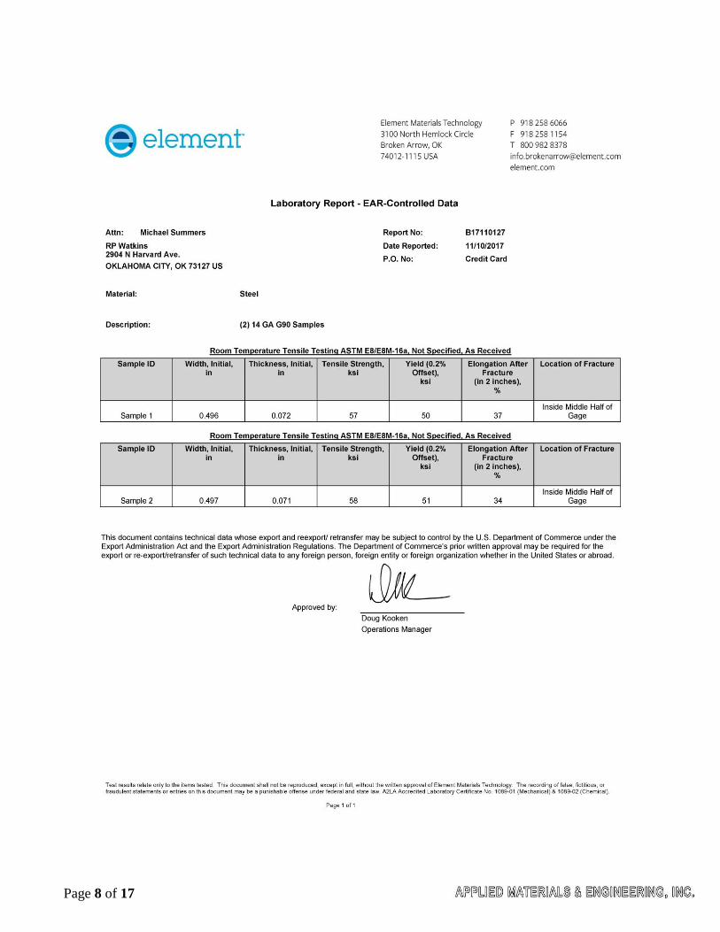
Page 8 of 17

Page 9 of 17

Page 10 of 17

Page 11 of 17
APPENDIX B

Page 12 of 17

Page 13 of 17
APPENDIX C

Page 14 of 17
Figure 1. Test Setup Figure 2. Test Setup Top View

Page 15 of 17
Figure 3. Test Setup- Right Joist Hanger
Figure 4. Test Setup- Left Joist Hanger

Page 16 of 17
APPENDIX D

Page 17 of 17
Figure 1. Typical failure mode of specimen at ultimate load
Figure 2. Typical failure mode of specimen at ultimate load.