Appendices Appendix D2 General Biological Assessment (MBA ...
Upload
nguyencongCategory
view
219download
3
- 1 -
ROW Maintenance Policy Appendices
Appendix 1 – Specification .............................................................................................. 2 Signs ..................................................................................................................... 2 Waymarking .......................................................................................................... 2 Furniture – (gates, stiles and bollards) ................................................................... 3 Structures .............................................................................................................. 4 Culverts ................................................................................................................. 4 Bridges .................................................................................................................. 4 Surfacing ............................................................................................................... 5
Typical blinded road arisings specification ......................................................... 5 Typical Specification of Dense Asphalt Concrete (formally Dense Bitumen Macadam) ......................................................................................................... 5 Routine Maintenance of Dense Asphalt Concrete.............................................. 5 Typical no-dig permeable surfacing ................................................................... 6
Appendix 2 - Working Practices ...................................................................................... 7 Waymarking .......................................................................................................... 7 Procurement .......................................................................................................... 7
Procurement sequence...................................................................................... 7 Inspections of Structures ....................................................................................... 8
Structures Inspection Form ................................................................................ 9 Avoidance of Underground Plant Procedure ........................................................ 10 Working with Volunteers ...................................................................................... 12
Appendix 3 - Outline of legislative framework for Maintenance ...................................... 15 Appendix 4 - Application to 3rd Parties to alter the Surface of a Public Right of Way Work Form .................................................................................................................... 16

- 2 -
Appendix 1 - Specifications
Signs New CBC signs have no brackets and are held by two stainless steel grub screws. However we also refurbish older designs and reinstall. Removed signs are either stored for reuse or shot blasted, repainted and then stored. Cast sign arms were developed in conjunction with Wilstead Patterns and Castings of Arlesey. There are specific castings for the inter-county promoted routes, The Icknield Way Trail and Greensand Ridge Walk. However the Icknield Way walkers route is indicated with flat plate aluminium (not cast) signs many of which have faded and which do not have text to indicate the status of the path and so are usually supplemented by another sign. Once the route has been reviewed it would be an option to replace the two signs with a single cast sign which would be consistent with the other signs in the Authority. Adding distances to signs Paragraph 14.5 of the Traffic Signs Manual Chapter 7 Design of Traffic Signs, "Metric distances are not permitted by the regulations and must not be used." Distances less than 3 miles may use fractions of a mile to the nearest 1/4 mile. Distances less than 1/2 a mile may be in yards. When a sign has more than one distance and at least one of the distances is in yards, then any distance in miles may have the abbreviation "m" for miles.
For most signs where there is only one distance or where all the distances are in miles, the "m" is omitted.
Waymarking Waymark Posts
Sawn redwood timber, tantalised to BS EN 335-1 class 4
2.1m x 100mm x 100mm four-way weathered and 450mm yellow painted top
Top painted with undercoat and 2 coats of non-drip gloss yellow paint.
To be installed 600mm into the ground. Waymark Discs Size: 85mm diameter Material: 3mm thick 80% recycled rigid pvc. Production: direct screen printed in two colours Colours: background, flood coated in bs 08 e 51. all text and arrow head black Fixing holes: 3 holes 3mm diameter equidistant on the perimeter

- 3 -
Furniture – (gates, stiles and bollards) All stiles on the Rights of Way Network are to be to the BS5709:2006. The supplier of galvanised gates was chosen by a procurement process carried out by CBC but included adjoining authorities Hertfordshire, Buckinghamshire, Cambridgeshire, Bedford Borough and Milton Keynes in 2011. Table of galvanised steel gate specifications as procurement process October 2011
Item Specification
All Gates to be all steel and galvanised to ENIS 1461
All nuts/bolts galvanised to ENIS 1461 or be Stainless Steel
Gates [except the Pedestrian Kissing Gate] to comply with BS5709:2006
Heights stated are approximate and taken from Ground Level.
Installation to the manufacturers instructions
Hand Gate
Gate within integral frame.
Height 1m. Opening of gate to 1m width.
Weld mesh panels across openings to height of approx. 750mm
Gate to be self-closing by an offset hinge.
The gate to latch to the frame when closed.
Pedestrian Kissing
Gate
Gate within integral frame.
Height 1m. Opening of gate to 1m width.
Weld mesh panels across openings to height of approx. 750mm
Gate to be self-closing by an offset hinge.
The gate to latch to the frame when closed.
Galvanised steel enclosure with weld mesh panels. Radius approx. 550mm
Large Pedestrian
Kissing Gate
Gate within integral frame.
Height 1m. Opening of gate to 1.2m width.
Weld mesh panels across openings to height of approx. 750mm
Gate to be self-closing by an offset hinge.
The gate to latch to the frame when closed.
Galvanised steel enclosure with weld mesh panels. Radius approx. 800mm
Radar Kissing Gate Gate within integral frame. Height 1m. Opening of gate to 1.2m width.
Gate to open in 1 direction (into the hoop enclosure) when locked or to open
away from the enclosure when unlocked. Lock to be of the National Key
Scheme (Radar) type. Gate to be Self-closing by offset hinges from either
direction.
Galvanised steel enclosure with weld mesh panels. Radius approx. 800mm
Two Way Bridlegate
With an opening 1.5m wide. Height of gate approx. 1.2m.
Galvanised steel gate with weld mesh panels.
Self-closing by offset hinges from either direction and with a tall handled
latch mechanism
Timber gates if and when used must be to BS5709:2006.

- 4 -
Structures Bridge or Culvert The decision about whether to install a free standing bridge or a culvert is dependent on the location and consent from the Internal Drainage Board or the Environment Agency. At smaller sizes, the difficulty of specifying bridleway bridges means that structures on bridleways are more likely than those on footpaths to be culverts.
Culverts For vehicular culverts of 0.9m and below in length the specification would be for Twin wall Ridgidrain pipe installed with ¼ of the diameter below bed level and with at least 0.9m of cover from the crown of the pipe to the finished surface. The headwalls will usually be pinned concrete sandbags. For non-vehicular culverts the cover might be reduced down to minimum of 450mm for bridleways and 300mm for footpaths.
Bridges Technical Approval shall be obtained for all new vehicular bridges and other bridges over 10m in length as specified in the Design Manual for Roads and Bridges, Volume 1 Highways structures: Approval procedures and general design. http://www.dft.gov.uk/ha/standards/dmrb/vol1/section1/bd205.pdf For non vehicular bridges, between 5 and 10m in length, the usual procedure will be to specify;
Supply & Install bridge with a galvanised steel beam and treated softwood timber deck with non-slip surface and two timber parapets to Eurocode 3 , Part 2-1 , BS EN 1993-2 (replaces BS 5400) including designing and building suitable concrete bank seats.
The steel beams of bridges should rest on suitable rubber bridge bearings. 1.2m is to be available width for footpaths and 1.5 – 2.0m for bridle and cycle bridges according to the level of usage.
For footbridges below 5m in length, designs will usually be a development of the Sawn Timber Footbridge from Footbridges in the Countryside Design and Construction 2nd Ed. (1989) Countryside Commission for Scotland. For bridle bridges below 5m, the options are to use the supply and install specification as above for non-vehicular bridges between 5-10m or to use the design for Sawn Timber Bridge from Path Bridges planning, design, construction and maintenance (2006) Produced by the Paths for All Partnership with support from Scottish Natural Heritage and Forestry Civil Engineering. Non-slip options include routed deckboards, encapsulated plywood panels with non-slip surface, routed deckboards with resin inserts and application of other proprietary coatings with containing aggregate or rubber.

- 5 -
Surfacing
Typical blinded road arisings specification
When improving an unsurfaced path it is likely that the existing natural surface should be excavated. The most common option is to remove half the total depth and put to each side, to be pulled back at the end, levelled and seeded. Alternatively if there is not enough width, the total depth may be excavated and removed from site. Optional Treated softwood edging - Install 150mm treated softwood edging with pegs 50 x 50 x 450mm
Install Terram 1000 or equivalent
Sub base of 100mm of crushed concrete/brick that is free from timber, glass, metal or any sharp material and organic matter. (Sub-base can be up to 200mm depending on softness of underlying ground and the topography).
Lay and roll 100mm depth of 32mm screened road risings with fall to side. The base layer may be as thin as 75mm and as deep as 150mm depending on the level and type of use).
Blind with granite or limestone (6mm to dust), to 10mm nominal depth [Optional]
Typical Specification of Dense Asphalt Concrete (formally Dense Bitumen Macadam)
For Vehicular Highways (Byways and other shared use Rights of Way)
Install Terram 1000 or equivalent
Install a sub base of MOT type 1 or screened road arisings (depth 100-200mm) dependent of ground conditions.
Lay a Base Course 60mm depth AC20 Dense Bin 100/50 (dense macadam binder course 0/20 size, 60mm thick).
Lay a 40mm AC 10 close surf 100/150.
For Footpaths
Install Terram 1000 or equivalent
Install a sub base of MOT type 1 or Screened road arisings (Depth ~100mm) dependent of ground conditions.
Lay a Base Course 40mm depth AC20 Dense Bin 100/50 (Dense macadam binder course 0/20 size, 60mm thick).
Lay a 25mm AC 10 close surf 100/150.
Routine Maintenance of Dense Asphalt Concrete
Routine surface defects shall be repaired by cutting back to solid construction, square and backfill with hot bituminous material. A cold lay material may be used as a temporary measure, if permanent patch repair or resurfacing work is then planned.

- 6 -
Typical no-dig permeable surfacing
Lay Treetex T300 geotextile Install 75mm deep Cellweb tree protection system pined with fixing pins as manufacturers instructions. Install 105mm depth of no fines angular fill 4-20mm within the open cells. That is overfilling by 30mm

- 7 -
Appendix 2 - Working Practices
Waymarking 1. All new locations and designs to be approved by area Rights of Way Officer. 2. No discs to be attached to trees 3. No duplicate discs to be added to existing locations – a single disc or existing
disc plus plaque should carry all the information necessary: status, direction, route identifier etc.
4. Waymarks visible from direction of approach and point along the path 5. Posts should be visible, away from farm machinery and protected from
livestock 6. In sensitive areas such as SSSI’s and Ancient Monuments, consent will be
required from the appropriate authority.
Procurement The CBC procurement procedures are to be followed. To ensure compliance the requisition sheets are completed and signed by the budget manager before the works are procured. More complicated works may require that a Method Statement and Risk assessments are provided.
Procurement sequence
1. Issue is to completed on CAMS as soon as identified. 2. Jobsheet to be completed including writing specification of works. 3. Worksheet to be produced including risk assessment form for each job 4. The appropriate Procurement procedure should be according to the expected
total value of the works. Up to £2000, two quotes such be obtained wherever possible. From £2000 to £20,000, a minimum of 3 written quotes. From £20,000 to £60,000, the PT38 Invitation to provide quotation lite form on the In-Tend corporate process. Above £60,000 with Intend (see the Procurement Section).
5. The lowest quote which is for the work as specified is always to be chosen except when using the PT38 form or Intend and explicitly stating the quality criteria on which the quote/tender is to be judged. Requisition form to be completed. All quotes are to be retained, and copies attached to the requisition form.
6. Budget Manager to sign requisition 7. Order to be written by procurer which includes worksheet number and send to
contractor. Order number is to be added to Requisition form which is filed with a copy of the order and all of the quotes, both successful and unsuccessful
8. The contractor can only start work when he has order. 9. Contractor is to report back to Contracts Officer and to send in invoice as soon
as work is completed 10. Row Officer or the Contracts Officer may inspect the works before confirming
that works have been completed. 11. ROW Officer to update CAMS in issue, job and worksheet. 12. Contracts Officer is to confirm that invoice can be paid or dispute invoice in
writing within 28 days.

- 8 -
Inspections of Structures Structures are classified as being surveyed by either an engineer or member of Rights of Way team according to their size and the users of the highway. For this purpose, it is all the legal users of the structure including private use. Table of classification and body to undertake surveys
Category Use Type Span
Surveyed by ROW Team
or Bedfordshire
Highways
A1 Pedestrian and/or Bridleway Pipe any ROW Officer
A2 Pedestrian and/or Bridleway Brick/Stone Arch <1.5m ROW Officer
A3 Pedestrian and/or Bridleway Structural Beam Timber (inc Kit) <5m ROW Officer
A4 Pedestrian and/or Bridleway Sleeper <5m ROW Officer
A5 Pedestrian and/or Bridleway Crash Barrier <5m ROW Officer
A6 Pedestrian and/or Bridleway Structural Beam Steel <5m ROW Officer
A7 Pedestrian and/or Bridleway Structural Beam Concrete <5m ROW Officer
A8 Pedestrian and/or Bridleway Concrete Slab (inc Box) <5m ROW Officer
A9 Vehicular Pipe <0.9m ROW Officer
A10 Vehicular Brick/Stone Arch <0.9m ROW Officer
A11 Vehicular Concrete Slab (inc Box) <0.9m ROW Officer
B1 Pedestrian and/or Bridleway Brick/Stone Arch 1.5m + Engineer
B2 Pedestrian and/or Bridleway Structural Beam Timber (inc Kit) 5m + Engineer
B3 Pedestrian and/or Bridleway Structural Beam Steel 5m + Engineer
B4 Pedestrian and/or Bridleway Structural Beam Concrete 5m + Engineer
B5 Pedestrian and/or Bridleway Concrete Slab (inc Box) 5m + Engineer
B6 Vehicular Pipe 0.9m + Engineer
B7 Vehicular Brick/Stone Arch 0.9m + Engineer
B8 Vehicular Structural Beam Steel 0.9m + Engineer
B9 Vehicular Structural Beam Concrete 0.9m + Engineer
B10 Vehicular Concrete Slab (inc Box) 0.9m + Engineer
D1 Retaining wall any <2m height ROW Officer
D2 Retaining wall any 2m + Engineer
D3 Cattle Grid Any Engineer
When structures are surveyed by an engineer, the engineer will provide the form to be used. For the bridges to be surveyed by a member of the ROW Officer, the Structures Inspection form (next page) will be used.

- 9 -
Structures Inspection Form
Number of:
CAMs Updated: Yes / No Contracts Officer Notified: Yes / No
Date: Date:
Instructions overleaf
Category Use Type Span
A1 Pedestrian and/or Bridleway Pipe any
A2 Pedestrian and/or Bridleway Brick/Stone Arch <1.5m
A3 Pedestrian and/or Bridleway Structural Beam Timber (inc Kit) <5m
A4 Pedestrian and/or Bridleway Sleeper <5m
A5 Pedestrian and/or Bridleway Crash Barrier <5m
A6 Pedestrian and/or Bridleway Structural Beam Steel <5m
A7 Pedestrian and/or Bridleway Structural Beam Concrete <5m
A8 Pedestrian and/or Bridleway Concrete Slab (inc Box) <5m
A9 Vehicular Pipe ≤0.9m
A10 Vehicular Brick/Stone Arch ≤0.9m
A11 Vehicular Concrete Slab (inc Box) ≤0.9m
B1 Pedestrian and/or Bridleway Brick/Stone Arch 1.5m +
B2 Pedestrian and/or Bridleway Structural Beam Timber (inc Kit) 5m +
B3 Pedestrian and/or Bridleway Structural Beam Steel 5m +
B4 Pedestrian and/or Bridleway Structural Beam Concrete 5m +
B5 Pedestrian and/or Bridleway Concrete Slab (inc Box) 5m +
B6 Vehicular Pipe >0.9m
B7 Vehicular Brick/Stone Arch >0.9m
B8 Vehicular Structural Beam Steel >0.9m
B9 Vehicular Structural Beam Concrete >0.9m
B10 Vehicular Concrete Slab (inc Box) >0.9m
D1 Retaining wall any <2m
D2 Retaining wall any 2m +
Total WidthGenerally the width of the deck, including the
parapet width. Contacts if needed:
Maximum Deck/Surface to Bed heightMeasurement from the top of the deck to the water
course bed.
ApproachThis is the lead up to the structure; including the
surroundings.
Parapet The handrails or safety guard Duty Officer No. 0300 300 8085
Beams The things the deck sit's on. Flytipping: 0300 300 8631/8632
Foundation This is the thing the beams sit on top of. Highways Helpline: 0300 300 8049
DPMThis is a plastic membrane used to stop the beams
rotting.
Wooden / Routed / Safety panel / Concrete / Aggregate / Other
Absent / Sleeper bearer / Concrete / Gabion / Brick
Deck
To Be Completed In The Office
Damp Proof Membrane (DPM): Y / N
Foundation Condition:
Condition:
Culvert pipe material: Plastic [twin wall Y / N] / Concrete / Brick /
ClayCulvert Surface:
Aggregate / Earth / Grass / Concrete / Asphalt / Other
Culvert width (m): Length (m):
Culvert pipe internal dia (m):
David Leverington Rights of Way Team Leader 0300 300 6107
or 07802 560642
Work Required
Contracts Officer: Date:
Chris Nicol Senior Rights of Way Officer - Contracts 0300 300
6230 or 07802 518984
Action/Work Ordered?
Signed when respective involvement complete:
Officer: Date:

- 10 -
Avoidance of Underground Plant Procedure This applies to works managed by the ROW elements of CBC Highways whether by Contractors, Volunteers or CBC Officers.

- 11 -
Avoidance of Underground Services Procedure
Objective To keep all excavations on Public ROW safe from underground services. To maintain compliance to legislation and HSE Guidance.
Input Works order procedure, HSE Guidance (HSG 47)
Output Excavations are controlled and risks are managed
Utility service plans to be provided by contractor
Locations are to be scanned for services and marked
Procedure Owner Contracts Officer/Designer
Steps in procedure
1. Decision Has an up to date underground service information been provided to cover the works area?
If Yes go to Step 3
If No go to Step 2.
2. Activity Request advice from Highways Assets
Suspend work and seek further information and clarity from the originator to ensure that Service information is provided.
3. Decision Looking at the Utility Service information provided, is Utility guidance needed?
If Yes go to step 4
if No go to step 5
----------------------------
At this stage it may also be necessary to contact the Service provider to take additional guidance e.g. BT – Dial B4U Dig, Electricity (High Voltage), Gas (High Pressure) and Water. If utilities are within 3m of the area to be excavated, then the Utility provider is to be contacted. For Gas and electricity this is by email [email protected]
4. Hold Point Is a redesign required ?
5. Procurement process
The specification of any works involving excavation must include Service search results. If these reveal that a Service is close to the works then the response of the utility company must also be included.
6. Activities Designer to Use ‘Cable Avoidance Tools’ to locate underground services (being a trained Operator) and mark then on the ground.
Depending on results of scanning, contact utility provider for guidance and risk assessment.
Photograph site showing marks.
Service providers such as British Telecom, Electrical or Gas companies should be contacted in the following circumstances.
• Additional guidance or site assistance is suggested in the search results. • Service shown on plan is not located. • Service within 3m of the dig area • Service identified as shallower than on the plan • Service embedded in the surround • Any damage to a service is discovered • For gas pipes, piling or vertical boring within 15m • Excavation with 10m of any above ground gas installation.

- 12 -
Working with Volunteers Work may be undertaken by volunteers on tasks organised by CBC. In these cases, CBC Officers should ensure that a Risk Assessment is undertaken and that the volunteers are appropriately briefed as to the task to be done and the equipment provided. Welfare A First Aid Kit of the appropriate capacity for the number of people on the task must be on site. Strimmers/brushcutters should only be used by appropriately LANTRA trained people. Further Guidance can be found on the Leisure Section. http://www.centralbedfordshire.gov.uk/leisure/countryside/volunteers/risk.aspx A example of a suitable Risk Assessment is shown on the next page.

- 13 -
���� ��Risk assessment
RISK ASSESSMENT FOR:
Volunteers working on Public Rights of Way
What are you risk assessing? Put in brief outline of the task/activity.
Volunteer task with an undetermined number of volunteers, cutting back a hedgerow to widen the usable width of the
Public Footpath.
Establishment:
Public Rights of Way Team, Highways
Assessment by:
Richard Thompson
Date:
Risk assessment number/ref:
HR/10/RA-17/11/2016
Manager Approval:
David Leverington
Date:
15.11.16
Location of Nearest Accident and Emergency
Dept.
Milton Keynes Hospital H8 Standing Way, Eaglestone, Milton
Keynes MK6 5LD
Grid Reference (if remote site):
SP9318 2891
Emergency Service Access:
From the A5 along Woburn Road to Overend Green Lane

- 14 -
Use this form to record the significant findings of your risk assessment and detail any action required to reduce risk further, where existing actions (control measures) are insufficient.
dd / mm / 20yy] (usually
What are the
hazards?
Who might be harmed
and how?
What are you already doing?
What further action is
necessary?
Action by
who?
Action by
when?
Done
Slips, trips and
falls
Volunteers may be injured if they
trip over objects or slip on wet
grass.
Cuts and abrasions, other
physical and major injuries.
Spills / trip hazards immediately identified and then
dealt with first
Appropriate footwear worn by all attendants.
Make everyone aware of the existing ground
conditions prior to arrival.
Ensure all trip hazards are removed
before leaving site
R Thompson 16th
November
(day before)
Weather
Cold wet weather – chill risk; torn/pulled muscles. Cold affecting dexterity and grip When using hand tools.
Appropriate clothing worn by all attendants, including
gloves
Make volunteers aware of the weather forecast
Provision of warm drinks & spare
gloves
Continuous monitoring of weather
conditions
R Thompson 16th
November
(day before)
Use of hand /
power tools
Volunteers may be injured if they
mishandle the equipment.
Cuts and minor injuries.
Ensure everyone knows how to use each tool
correctly and which tool to use for the task and
continuously monitor. Tools & Safety talk.
Only those trained to use power tools (hedge cutters
& strimmers) are able to do so.
Check training qualifications for
power tools.
R Thompson 17th
November
Bending and lifting
Volunteers may be injured
through carrying too much and
incorrect lifting technique.
Remind volunteers how to bend safely and to stretch
regularly. Also not to move heavy loads.
Provide a wheel barrow to help
move hedge cuttings
R Thompson 17th
November
Diseases Volunteers may come into contact
with dog mess.
Warn volunteers to be careful while working and to
ensure they use gloves when working.
17th
November
Other people
Volunteers working in close
proximity to each other and
members of the Public walking
through the task area.
Cuts and abrasions, other
physical and major injuries.
Ensure volunteers are aware of the dangers of close
working and the potential of members of the public
using the footpath during the task.
Stop work while members of the public pass.
Ensure ‘Men at Work’ warning signs
at the entrance to the Footpath are
in place before work commences.
Provide Hi Vis waist coats for
volunteers
R Thompson 17th
November

- 15 -
Appendix 3 - Outline of legislative framework for Maintenance Highway maintenance is currently mainly covered by the following legislation:
Countryside Act 1968 s 27; our Duty to maintain signs http://www.legislation.gov.uk/ukpga/1968/41/section/27 Highways Act 1980 [subsequently amended by the Rights of Way 1990 and Countryside and Rights of Way Act 2000] http://www.legislation.gov.uk/ukpga/1980/66
section 41; our duty to maintain highways maintainable at public expense
section 51; removal of common law obligation to maintain a highway by reason of enclosure - consent to enclosure received from highway authority
section 130; our duty to assert and protect rights of the public “(1) It is the duty of the highway authority to assert and protect the rights of the public to the use and enjoyment of any highway for which they are the highway authority, including any roadside waste which forms part of it.”
section 131A; response to unlawful disturbance[s] of the surface
section 134; dealing with the ploughing of footpaths or bridleways
section 135; authorisation of other works that disturb the surface
section 137A; dealing with interference by crops
section 143; power to remove structures
section 145; powers as to gates and their width
section 146; our duty to maintain [stiles and] gates
section 147; power to authorise erection of [stiles and] gates
section 149; removal of deposits from considered a nuisance
section 153 prohibiting doors, gates or bars opening onto the highway.
Schedule 12a; powers in relation to interference with highways

- 16 -
Appendix 4 - Application to 3rd
Parties to alter the Surface of a Public Right of Way Work Form
- 17 -
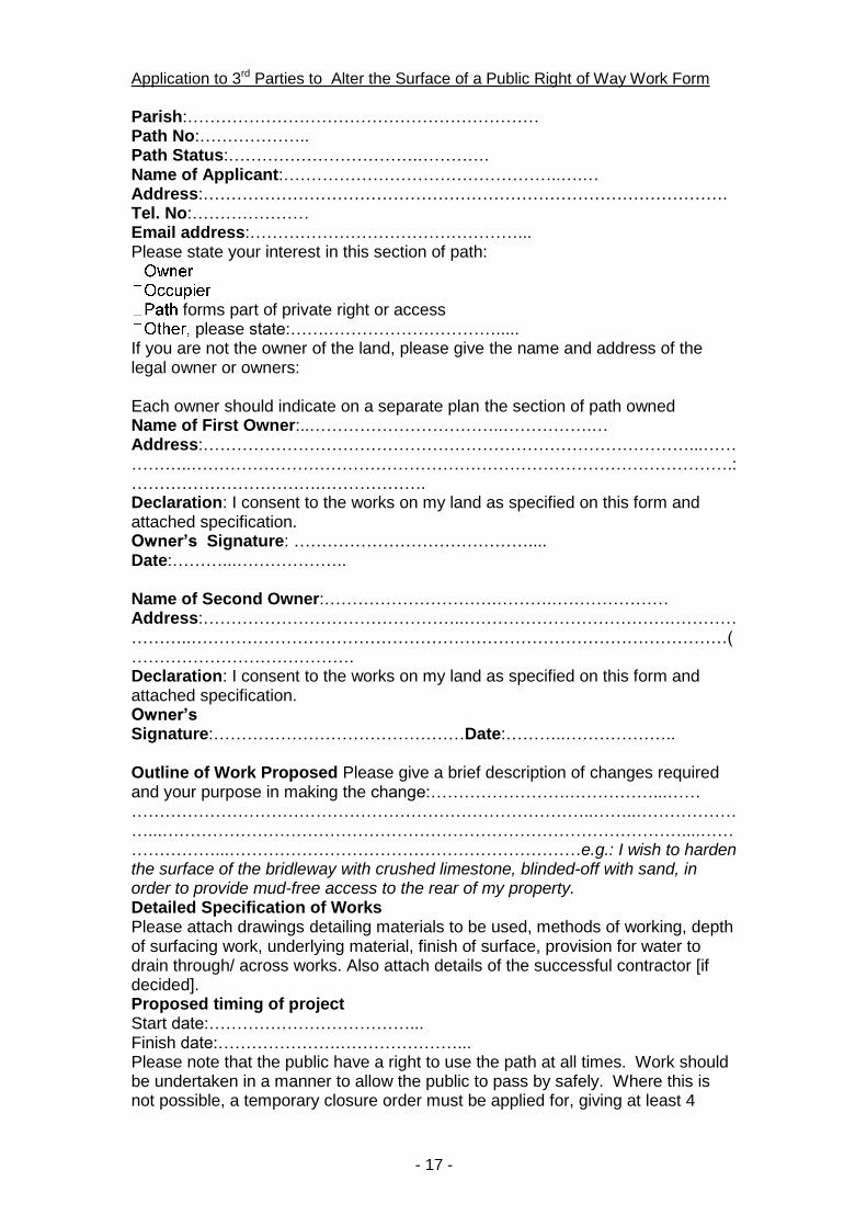
Application to 3rd Parties to Alter the Surface of a Public Right of Way Work Form
Parish:……………………………………………………… Path No:……………….. Path Status:…………………………….…………. Name of Applicant:…………………………………………..….… Address:………………………………………………………………………………….Tel. No:………………… Email address:…………………………………………... Please state your interest in this section of path:
forms part of private right or access please state:…….………………………….....
If you are not the owner of the land, please give the name and address of the legal owner or owners: Each owner should indicate on a separate plan the section of path owned Name of First Owner:..……………………………..…………….… Address:……………………………………………………………………………...……………..…………………………………………………………………………………….: …………………………….………………. Declaration: I consent to the works on my land as specified on this form and attached specification. Owner’s Signature: …………………………………….... Date:………...……………….. Name of Second Owner:………………………….……….………………… Address:………………………………………..……………………………….…………………..……………………………………………………………………………………( …………………………………. Declaration: I consent to the works on my land as specified on this form and attached specification. Owner’s Signature:………………………………………Date:………..……………….. Outline of Work Proposed Please give a brief description of changes required and your purpose in making the change:…………………….……………...…… ………………………………………………………………………..……..…………………...…………………………………………………………………………………....…………………...………………………………………………………e.g.: I wish to harden the surface of the bridleway with crushed limestone, blinded-off with sand, in order to provide mud-free access to the rear of my property. Detailed Specification of Works Please attach drawings detailing materials to be used, methods of working, depth of surfacing work, underlying material, finish of surface, provision for water to drain through/ across works. Also attach details of the successful contractor [if decided]. Proposed timing of project Start date:………………………………... Finish date:………………….…………………... Please note that the public have a right to use the path at all times. Work should be undertaken in a manner to allow the public to pass by safely. Where this is not possible, a temporary closure order must be applied for, giving at least 4

- 18 -
weeks notice. This will be charged for. The costs are available on our website. These costs cover administration fee as well as advertising in a local paper. Permission given by the Highways Authority for work on the right of way does not imply planning permission. You are advised to contact our Planning Department [03003008000] to ensure that planning permission for the works is not required. Applicant’s Declaration I hereby apply for permission to carry out the works detailed in this application. I confirm that the works will be carried out in accordance with current Health and Safety Regulations, the Environmental Protection Act 1990, Waste Regulations and the Detailed Specification of Works given in this application. Applicant’s Signature…………………………...…Date:…….………………… Checklist
1. This Form 2. Plan showing the extent of the works 3. Specification of Works 4. Landownership maps if the applicant is not the owner. 5. Timing of Project
Signed by applicant Completed applications should be sent to: Highways, Priory House, First Floor - East, Monks Walk, Chicksands, SG17 5TQ