
Rover C - woodmercator.com · The Biesse Rover C series machining centres are specifically designed...
30
Rover C Numerical control machining centres Centres d'usinage à contrôle numérique CNC-gesteuerte Bearbeitungszentren
Transcript of Rover C - woodmercator.com · The Biesse Rover C series machining centres are specifically designed...

Rover CNumerical control machining centresCentres d'usinage à contrôle numériqueCNC-gesteuerte Bearbeitungszentren

2
Rover CVesatile, powerful and easy to useEclectique et simple à utiliserVielseitig, stark und benutzerfreundlich

3
The Biesse Rover C series machining centres are specifically designed to be used in highly demanding environments, asmillwork, where extra large tools and aggregates are required. Rover C introduces innovative technological solutions and rigiddesign that guarantees high quality finish and great reliability under any working conditions. The Biesse operating unit with 5interpolating axes allows to perform complex machinings ensuring quality and precision.
Les centres d'usinage Biesse de la série Rover C ont été spécialement conçus pour les usinages lourds exigeant de grands outils etagrégats. Des solutions technologiques innovatrices comme les groupes opérateurs configurables et des caractéristiques constructivesparticulières assurent une excellente qualité de finition et une grande fiabilité. L’unité opératrice à 5 axes interpolants Biesse permet desusinages complexes en garantissant qualité et précision.
Die Bearbeitungszentren Rover C wurden speziell für schwere Bearbeitungsbedingungen entwickelt, die den Einsatz von großenWerkzeugen und Aggregaten erfordern. Innovative technologische Lösungen, weitgehend konfigurierbare Arbeits-gruppen undextrem solide Bauweise sichern eine hohe Fertigungsqualität und große Zuverlässigkeit unter jeder Arbeitsbedingung. Der 5-Achs-Kopf von Biesse ermöglicht die Ausführung von komplexen Formen und Bögen höchster Qualität und Präzision.
4
Rover C Higher standards on any applicationUsinages réalisés dans les règles de l'artZahlreiche Bearbeitungen mit höchstem Standard
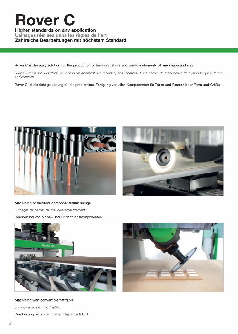
Rover C is the easy solution for the production of furniture, stairs and window elements of any shape and size.
Rover C est la solution idéale pour produire aisément des meubles, des escaliers et des parties de menuiseries de n'importe quelle formeet dimension.
Rover C ist die richtige Lösung für die problemlose Fertigung von allen Komponenten für Türen und Fenster jeder Form und Größe.
Machining with convertible flat table.
Usinage avec plan modulable.
Bearbeitung mit abnehmbaren Rastertisch CFT.
Machining of furniture components/furnishings.
Usinages de parties de meubles/ameublement.
Bearbeitung von Möbel- und Einrichtungskomponenten.

5
Machining of frames withirregular shapes.
Usinage de portes et fenêtres de forme irrégulière.
Bearbeitung auch von nichtrechteckigen Türen undFenstern.
Machining of arched windows.
Usinage de fenêtres cintrées.
Bearbeitung von bogenförmigenFenstern.

6
Rover CHigher standards on any applicationUsinages réalisés dans les règles de l'artZahlreiche Bearbeitungen mit höchstem Standard
Machining of stairelements.
Usinage de partiesd'escaliers.
Bearbeitung vonTreppen.
Machining of shutters.
Usinage de persiennes.
Bearbeitung vonFensterläden.

7
Machining of core panel doors.
Usinage de portes à âme alvéolaire.
Bearbeitung von Furniertüren.
Machining of solid wood doors and gates.
Usinage de portes en bois massif.
Bearbeitung von Türen aus Massivholz.

8
Rover CVarious versatile configurationsDiverses configurations éclectiquesVerschiedene Konfigurationen für vielseitige Anwendungen
5 operating units grant the utmost flexibility and maximum productivity.
La flexibilité extrême et la grande productivité sont garanties par 5 groupes opérateurs.
Bis zu 5 Bearbeitungseinheiten ermöglichen hohe Flexibilität und maximale Produktivität.

9
P3
A B-CE- B*-NCE- C MAXmm/inch mm/inch mm/inch mm/inch mm/inch
Rover C 6.40/9.40 3390/133.5 995(1580**)/39.1(62.2**) 1580/62.2 1535-1935/60.4-76.1 1550-1950/61-76.71Rover C 6.50/9.50 4600/181.1 1600(2185**)/62.9(86**) 2185/86 1535-1935/60.4-76.1 1550-1950/61-76.71Rover C 6.65/9.65 6200/244.1 2400(2985**)/94.4(117.5**) 2985/117.5 1535-1935/60.4-76.1 1550-1950/61-76.71
P1 P2
A1 A3A2
Each front configuration (A1, A2, A3) can be combined with any of the rear configurations (P1, P2, P3).
Les configurations avant (A1, A2, A3) peuvent se combiner avec n'importe quelle configuration arrière (P1, P2, P3).
Jede vordere Konfiguration (A1, A2, A3) kann mit jeder hinteren Konfiguration kombiniert werden (P1, P2, P3).
*Maximum dimensions of the loadable panel on side and central stops for non CE machines.*Dimensions maximum de la pièce à charger contre les butées latérales et centrales en cas de machine non CE.*Max. Plattenabmessungen an den Seiten und Mittelanschlägen für Nicht CE Maschinen.
**Maximum dimensions of the loadable panel on side stops for CE machines.**Dimensions maximum de la pièce à charger contre les butées latérales en cas de machine CE.**Max. Plattenabmessungen an den Seitenanschlägen für CE Maschinen.
Working fieldsChamps d'usinageArbeitsbereich

10
Rover CVarious versatile configurationsDiverses configurations éclectiquesVerschiedene Konfigurationen für vielseitige Anwendungen
The 5-axes operating unit, compact but technologically advanced, allows the machining of panels with high thickness and complexshapes.
L’unité opératrice à 5 axes, compacte et puissante, permet d'usiner des pièces très épaisses et de formes complexes.
Der kompakte aber fortschrittliche 5-Achskopf ermöglicht die Bearbeitung von großen Werkstückstärken und komplexen Geometrien.

A1
P1P1
P2 P2
A1A1
5 AXES 11 kW – HSK F63 / BH42 L5 AXES 11 kW – HSK F63 / BH42 L5 ACHS 11 kW – HSK F63 / BH42 LCE.
5 AXES 10.5 kW – HSK F63 / BH225 AXES 10.5 kW – HSK F63 / BH225 ACHS 10.5 kW – HSK F63 / BH22
5 AXES 11 kW – HSK F63 / BH315 AXES 11 kW – HSK F63 / BH315 ACHS 11 kW – HSK F63 / BH31
5 AXES 11 kW – HSK F63 / BH9 5 AXES 11 kW – HSK F63 / BH95 ACHS 11 kW – HSK F63 / BH9
Operating unit configurationConfiguration groupe opérateurKonfiguration der Arbeitseinheit

12
A B-CE- B*-NCE- C MAXmm/inch mm/inch mm/inch mm/inch mm/inch
Rover C 6.40/9.40 3390/133.5 995(1580**)/39.1(62.2**) 1580/62.2 1535-1935/60.4-76.1 1550-1950/61-76.71Rover C 6.50/9.50 4600/181.1 1600(2185**)/62.9(86**) 2185/86 1535-1935/60.4-76.1 1550-1950/61-76.71Rover C 6.65/9.65 6200/244.1 2400(2985**)/94.4(117.5**) 2985/117.5 1535-1935/60.4-76.1 1550-1950/61-76.71
5 AXES 10.5 kW – HSK F63 / BH315 AXES 10.5 kW – HSK F63 / BH31
5 ACHS 10.5 kW – HSK F63 / BH31
*Maximum dimensions of the loadable panel on side and centralstops for non CE machines.*Dimensions maximum de la pièce à charger contre les butées latérales etcentrales en cas de machine non CE.*Max. Plattenabmessungen an den Seiten und Mittelanschlägen fürNicht CE Maschinen.
**Maximum dimensions of the loadable panel on side stops for CEmachines.**Dimensions maximum de la pièce à charger contre les butées latéralesen cas de machine CE.**Max. Plattenabmessungen an den Seitenanschlägen für CEMaschinen.
Working fieldsChamps d'usinageArbeitsbereich

Many machinings performed with no imperfectionsTous les usinages sont exécutés dans les règles de l'artVielfältige Bearbeitungen fachgerecht ausgeführt

14
ISO30HSK F63
HSK F63
HSK F63ISO30HSK F63
ISO30HSK F63
ISO30HSK F63
ISO30HSK F63
ISO30HSK F63
ISO30HSK F63
ISO30HSK F63
Rover CResponding to every needLa réponse à toutes vos exigencesDie Antwort für jede Anforderung
15
Better finish, higher productivity and tooling speedFinition optimale, productivité et vitesse d'outillage supérieuresHöhere Produktivität, besseres Endergebnis bei geringere Rüstzeit
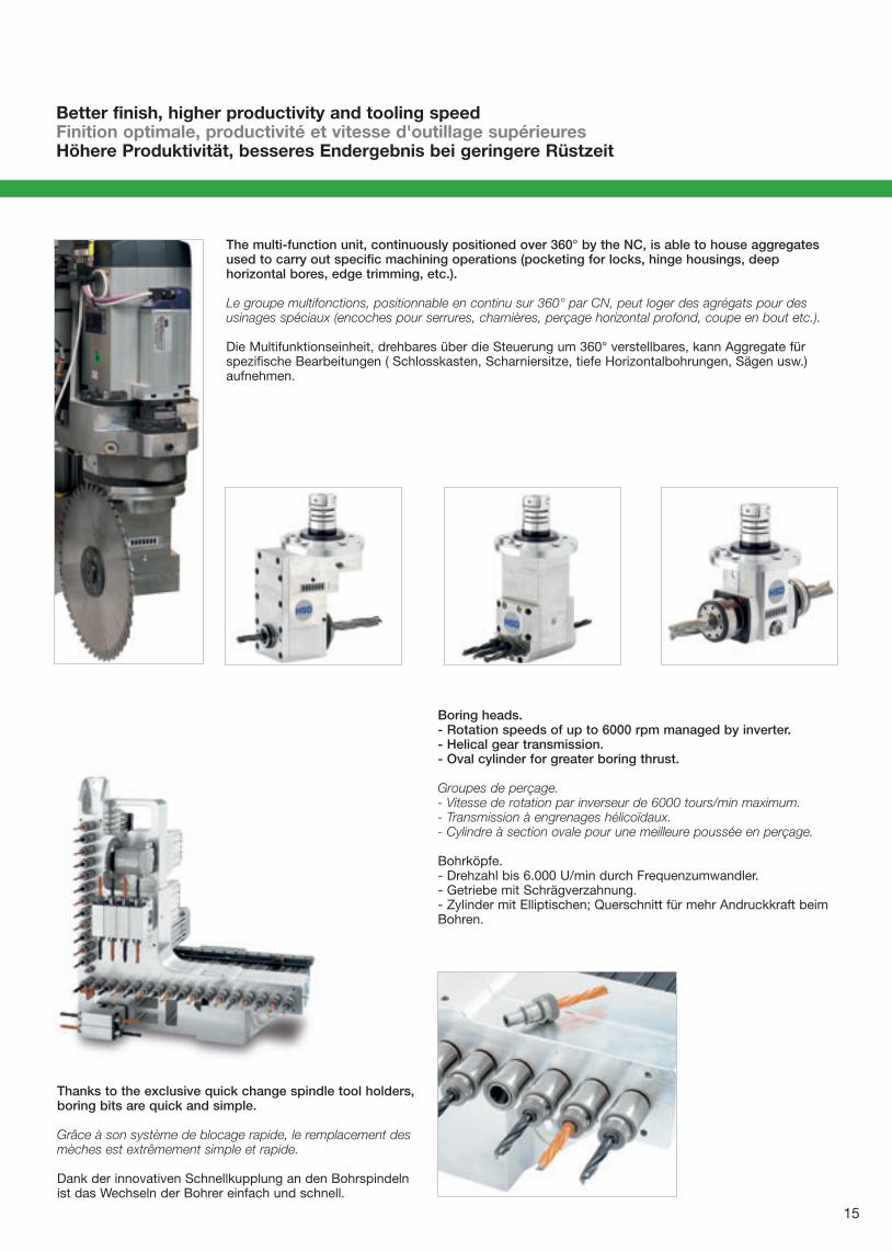
Boring heads.- Rotation speeds of up to 6000 rpm managed by inverter.- Helical gear transmission.- Oval cylinder for greater boring thrust.
Groupes de perçage.- Vitesse de rotation par inverseur de 6000 tours/min maximum.- Transmission à engrenages hélicoïdaux.- Cylindre à section ovale pour une meilleure poussée en perçage.
Bohrköpfe.- Drehzahl bis 6.000 U/min durch Frequenzumwandler.- Getriebe mit Schrägverzahnung.- Zylinder mit Elliptischen; Querschnitt für mehr Andruckkraft beimBohren.
Thanks to the exclusive quick change spindle tool holders,boring bits are quick and simple.
Grâce à son système de blocage rapide, le remplacement desmèches est extrêmement simple et rapide.
Dank der innovativen Schnellkupplung an den Bohrspindelnist das Wechseln der Bohrer einfach und schnell.
The multi-function unit, continuously positioned over 360° by the NC, is able to house aggregatesused to carry out specific machining operations (pocketing for locks, hinge housings, deephorizontal bores, edge trimming, etc.).
Le groupe multifonctions, positionnable en continu sur 360° par CN, peut loger des agrégats pour desusinages spéciaux (encoches pour serrures, charnières, perçage horizontal profond, coupe en bout etc.).
Die Multifunktionseinheit, drehbares über die Steuerung um 360° verstellbares, kann Aggregate fürspezifische Bearbeitungen ( Schlosskasten, Scharniersitze, tiefe Horizontalbohrungen, Sägen usw.)aufnehmen.

16
Rover CTool changersMagasins outilsWerkzeugwechsler
The chain tool change magazine can house large tools and aggregates. It enables simultaneous changing of two tools, thushalving tool change time and increasing productivity.
Le magasin outils à chaîne peut loger des outils et des agrégats de grande taille. Il permet de remplacer simultanément deux outils enréduisant de moitié le temps de changement d'outil et en augmentant d'autant la productivité.
Der Kettenwerkzeugwechsler kann große Werkzeuge und Aggregate aufnehmen und ermöglicht den gleichzeitigen Wechsel von zweiWerkzeugen, wodurch die Zeit für den Wechsel halbiert und die Produktionsleistung gesteigert wird.
The revolver type tool change magazine, mounted on an independent Z carriage, allows tools to be changed while the machineis carrying out other operations.
Le dispositif de changement d'outil à revolver, monté sur le chariot Z, permet de remplacer outils et agrégats tandis que la machineexécute d'autres usinages, en réduisant ainsi les temps d'usinage.
Der auf dem Z-Achsenträger montierte Revolverwerkzeugwechsler ermöglicht das Wechseln von Werkzeugen und Aggregaten,während die Maschine andere Operationen ausführt, wodurch die Bearbeitungszeiten verringert werden.

17
Chip reading system integrated in the tool holder, forautomatic tool recognition.
Système de lecture de la puce intégrée dans le porte-outil, pourreconnaître automatiquement les outils.
Chiplesesystem des in der Werkzeugaufnahme integriertenChips zur automatischen Erkennung der Werkzeugdaten.
Belt tool changer with 15 places for 5 axes unit.
Magasin outils à chaîne de 15 places pour unité de façonnageà 5 axes.
Kettenwerkzeugwechselmagazin mit 15 Plätzen für 5-Achs-Kopf.
New Flexstore C with 44 positions.
Nouveau magasin outils Flexstore C à 44 positions.
Neue Flexstore C mit 44 Plätzen erhältlich.
State-of-the-art technologyTechnologie d’avant-gardeModernste Technologie

18
Modules for vacuum locking system.
Etaux pour système de blocage à vide.
Vakuummodule.
Uniclamp modules for pneumatic system.
Etaux Uniclamp pour système pneumatique.
Pneumatische Spannelemente UNICLAMP.
Rover CThe most flexible work tablePlan de travail répondant à toutes les exigencesDer Arbeitstisch für jede Anforderung
The innovative ATS (Advanced Table setting-System) is the mostadvanced table design in the industry. ATS has a universal designfor great flexibility and fast setup. ATS work table is covered byexclusive patents allowing for rapid locking of pieces of anyshape and size, with a drastic reduction in setup time. The quickchange coupling system guarantees fast, simple replacement ofthe vacuum units and Uniclamps used to lock narrow andparticularly thick pieces.
Le plan de travail innovateur ATS (Advanced Table setting-System) estun brevet exclusif Biesse. Il permet de bloquer rapidement des piècesde n'importe quelle forme et taille et de réduire drastiquement lestemps d'outillage. Le système de prise rapide permet une substitutionsimple des modules à vide avec les étaux pour bloquer aussi bien despièces étroites et que des pièces épaisses.
Der innovative Arbeitstisch ATS (Advanced Table setting-System) istein exklusives Biesse-Patent und ermöglicht ein schnelles Spannender Werkstücke jeder Form und Größe, dadurch werden dieRüstzeiten drastisch reduziert. Das Kupplungssystem garantiertden problemlosen und schnellen Austausch der Vakuummodulegegen die Spannvorrichtungen für schmale und dicke Werkstücke.

19
EPS (Electronic Positioning System) is the Biesse system thatis widely used for panel machining and for the production ofdoors, windows and stairs. EPS (X- Y) version allows the entireworking area to be reconfigured automatically in less than 30seconds. It positions the panel supports and carriages usingindependent drives, and therefore without using the operatingsection. Positioning of panel supports and carriages within anarea is carried out in masked time, while the machine isworking in the opposite area. It is also possible to carry outpendular machining operations on different elements. EPS (X)version is also available for the automatic positioning of thework tables.
EPS (Electronic Positioning System): c'est la solution Biesse pour laproduction de portes, fenêtres et escaliers. La version EPS (X-Y)permet de reconfigurer automatiquement toute la zone d'usinageen moins de 30 secondes. Place les plans et les chariots grâce àdes motorisations indépendantes, sans utiliser l'unité d'usinage. Lepositionnement des plans et des chariots d'une zone a lieu entemps masqué pendant que la machine usine sur la zone opposée.Il est possible d'usiner, en pendulaire, des éléments différents entreeux. La version EPS (X) est à présent disponible pour unpositionnement automatique des plans d’usinage.
EPS (Electronic Positioning System) ist die Biesse-Lösung, diesowohl für die Plattenbearbeitung als auch für die Herstellungvon Türen, Fenstern und Treppen eingesetzt wird. Dabei wird dergesamte Arbeitsbereich in weniger als 30 Sekunden neugerüstet. Das System positioniert die Werkstückauflagen undSauger mittels unabhängiger Motoren, das heißt, dieBearbeitungseinheit wird für diesen Vorgang nicht benötigt oderbeeinträchtigt. Die Positionierung von Werkstückauflagen undSaugern eines Bereichs erfolgt, während die Maschine auf deranderen Seite arbeitet. Es können auch Pendelbearbeitungenvon mehreren Elementen durchgeführt werden.
The Biesse switching system of locking modules (automatic with EPS, manual with ATS) allows the machining all the four sidesof the panel.
Le système de changement d'étaux Biesse (automatique avec EPS, manuel avec ATS) permet l'usinage des quatre côtés des éléments.
Das Umspannen der Biesse Spannelemente (automatisch mit EPS, manuell mit ATS-Tisch) erlaubt die Fertigbearbeitung aller vierWerkstückflächen.
Hyperclamp modules for rigid and precise lockings.
Etaux Hyperclamp pour blocages rigides et précis.
Hyperclamp-Module für stabiles und präzises Spannen.
Guaranteed reliability Fiabilité Garantierte Zuverlässigkeit

20
Rover CLocking of various componentsBlocage de divers composantsAufspannen verschiedener Werkstücke
The multi-positioning system allows locking of the elements to be processed, thus optimising machining operations,minimizing the number of tool changes and reducing overall production times.
Grâce au système de positionnement multiple l'on peut bloquer les éléments à usiner tout en optimisant les usinages, et enréduisant le temps total de production.
Dank dem System der Mehrfachbelegung können die zu bearbeitenden Werkstücke aufgespannt werden, wodurch dieBearbeitungen pro Zyklus optimiert und die Gesamtproduktionszeit verringert wird.

21
Main controls always within reachLes commandes principales sont toujours à portée de mainDie Hauptfunktionen sind stets griffbereit
Key pad to manage the main machine functions during the working area, and tool setup.
Tableau à poussoirs de contrôle pour gérer les fonctions principales de préparation de la zone d'usinage et d'outillage des groupesopérateurs et des magasins porte-outils.
Die Fernbedienung ermöglicht alle Hauptfunktionen für das Rüsten des Arbeitsbereiches sowie das Bestücken derBearbeitungseinheit und der Werkzeugwechsler.
Biesse has always been careful to comply with international regulations on dust emissions in the air. In developing this project,all attempts have been made to reduce the emission of dust into the air to a minimum.
Biesse a toujours respecté les normes internationales relatives aux poussières fibreuses. Lors du développement du projet, la réductionde l'émission de poussières a été sa priorité absolue.
Biesse legt schon immer größten Wert auf die Einhaltung der internationalen Normen z.B. die Grenzwerte für Luftstäube. Bei derAusarbeitung eines Maschinenprojekts wird nach Lösungen gesucht, um die Emission von Stäuben in die Luft auf ein Minimum zubegrenzen.
Numerically controlled chip deflector.
Transporteur de copeaux géré par contrôle numérique.
Spänetransportband.
Driven conveyors for removal of chips and waste material.
Tapis motorisés pour l'élimination des copeaux et des déchets.
Motorisierte Förderbänder zur Abführung von Spänen undBearbeitungsabfällen.

22
Rover CHardwareMatérielHardware
Rover C has a powerful numerical control. The exclusive Mechatrolink digital technology for the axes control is immune toenvironmental interference and guarantees precision and reliability.
Rover C a un puissant contrôle numérique. Le système Mechatrolink exclusif de commande numérique assure précision et fiabilité, touten éliminant les interférences typiques des systèmes analogiques.
Rover C ist mit einer leistungsstarken CNC-Steuerung. Das digitale Mechatrolink- System der Achsen verhindert die bei AnalogenSystemen typischen Interferenzen wodurch Präzision und Zuverlässigkeit gewährleistet werden.
PC-based BH660 Numerical Control:- Microsoft Windows operating system
controlling the machine and the user interface;
- axes real-time control;- input/outputs management;- real-time execution of machine logic;- bar code reader ready;- optional connection of a laser profile
projector;- specific machine function enable
buttons.
Système de contrôle BH660 sur base PC:- PC avec système opératif Windows
temps-réel pour le contrôle de la machine et de l'interface utilisateur;
- contrôle axes interpolés en temps réel;- gestion des signaux d'entrée/sortie;- exécution, en temps réel, de la logique
machine;- gestion du lecteur de codes barres;- possibilité de raccorder un projecteur laser
de profils;- touches spéciales pour activer certaines
fonctions de la machine.
Steuerung BH660 auf PC-Basis:- PC mit Windows-Betriebssystem für die
Steuerung der Maschine und der Benutzerschnittstelle;
- Kontrolle der interpolierten Achsen in Echtzeit;
- Verwaltung der Input/Output-Signale;- Ausführung der Maschinenlogik in
Echtzeit;- Anschluß eines Barcode-Lesegeräts;- Anschlußmöglichkeit eines
Projektionslasers;- Aktivierung von speziellen
Maschinenfunktionen über Softkey Tasten.

23
Maximum operator safetySécurité de l'opérateur maximumMaximale Sicherheit des Bedieners
All-round protection of the working unit:- ample front opening to facilitate access during tooling
operations;- maximum visibility for safe operation.
Protection intégrale du groupe opérateur:- large ouverture arrière pour faciliter l'accès aux opérations
d'outillage;- visibilité maximale pour travailler en toute sécurité.
Integraler Schutz der Arbeitsgruppe:- agroße vordere Öffnung gestattet dem Bediener ein einfaches
Bestücken des Bearbeitungkopfes;- perfekte Sicht beim Arbeiten bei maximaler Sicherheit.
Pneumatically controlled mobile curtain guard system tofacilitate piece loading operations and checking of the toolpath during simulation.
Système de bandes mobiles à commande pneumatique pourfaciliter les opérations de chargement de la pièce et de contrôledu parcours de l'outil en simulation.
System von beweglichen Schutzbändern mit pneumatischemHub zur Vereinfachung der Werkstückbeladung und derKontrolle des Werkzeugwegs in der Simulation.
Safety devices to protect againstaccidental impact:- contact mats;- perimeter guards with entrance
door and safety device.
Safety devices to protect against flyingelements:- 22 layers of side curtain guards
protecting the working unit;- transparent, shatterproof
polycarbonate panel protecting theworking unit;
- shatterproof polycarbonate panels onthe rear side of the perimeter guard.
Dispositifs de sécurité contre les chocsaccidentels:- tapis de détection;- protections périmétrales avec
porte et dispositif de sécurité.
Dispositifs de sécurité contre lesprojections:- 22 couches superposées de bandes
latérales de protection du groupeopérateur;
- panneau transparent en polycarbonate armé de protection du groupe opérateur;
- panneaux en polycarbonate armé sur le côté arrière de la protection périmétrale.
Sicherheitsvorrichtungen zum Schutz gegen Kollision:- Trittmatten;- Schutzgitter mit Tür und
Sicherheitsvorrichtung.
Sicherheitsvorrichtungen zum Schutzgegen umherfliegende Teile:- 22 übereinander liegende Schichten von
Schutzbändern zum Schutz der Arbeitsgruppe;
- transparenter bruchsicherer Kunststoffplatte aus Polykarbonat vorder Bearbeitungseinheit;
- Kunststoffpaneele aus Polycarbonat an der Rückseite des Schutzgitters.

24
BiesseCabinet is the software solution for designing office and domestic cabinets.BiesseCabinet integrates perfectly with BiesseWorks and lets you generateprograms and work lists directly.
BiesseCabinet est le logiciel de projection d’armoires de bureau et d’ameublement. Ilest intégré à BiesseWorks et permet de générer directement des programmes et deslistes d’usinage.
BiesseCabinet ist eine Software zum Konstruieren von Büro- und Wohnmöbeln.BiesseCabinet ist komplett in BiesseWorks integrierbar und kann Programme undArbeitslisten direkt erstellen.
Rover CSoftwareLogicielSoftware
The BiesseWorks graphic interface makes full use of the operating methodstypical of the Windows operating system:- assisted graphic editor used to program machining operations;- parametric programming and guided creation of parametric macros;- import of CAD and other external software files in DXF and CID3 format.
L'interface graphique à fenêtres BiesseWorks utilise les modes opératifs typiques du système opératif Windows:- éditeur graphique assisté pour la programmation des usinages;- programmation paramétrique et création guidée de macros paramétriques;- importation de fichiers de la CAO et d’autres logiciels externes en format DXF et CID3.
Die Grafische Bedienerschnittstelle ist voll Windows kompatibel undbeinhaltet:- geführter Grafik-Editor für die Programmierung der Bearbeitungen;- parametrische Programmierung und Menügeführte Erstellung von
parametrischen Makros;- Import von Dateien von CAD und anderen externen Software im Format
DXF und CID3.

25
BiesseDoor is the perfect solution for the parametric design of standard andspecial routed doors or door elements. This easy to use system provides anentrylevel solution for designing and manufacturing doors on Biesse machiningcentres.
BiesseDoor est la solution idéale pour la projection paramétrique de portes standard oufraisées. Simple à utiliser, c’est la solution de base pour la projection et production deportes avec les centres d’usinage Biesse.
BiesseDoor ist die ideale Lösung für das parametrische Konstruieren von Blatt- oderRahmentüren, nicht nur im Standardbereich sondern auch für Spezialtüren. Dasbenutzerfreundliche System bietet eine Einstiegslösung für das Erstellen undBearbeiten von Rahmen- oder Blatttüren auf Biesse Bearbeitungszentren.
BiesseWin is the perfect solution for the parametric design of windows and doors.This easy to use system provides an entry-level solution for designing andmanufacturing windows on Biesse machining centres.
BiesseWin est la solution idéale pour la projection paramétrique de portes et fenêtres.Simple à utiliser, c’est la solution de base pour la projection et production de portes etfenêtres avec les centres d’usinage Biesse.
BiesseWin ist die ideale Lösung für die parametrische Gestaltung von Fenstern undTüren. Das benutzerfreundliche System bietet eine Einstiegslösung für das Erstellenund Bearbeiten von Rahmenteilen auf Biesse Bearbeitungszentren.
SoftwareLogicielSoftwareе

26
The transversal carriage (Y axis) and the vertical carriage (Zaxis)are made of lightweight aluminium alloy, stabilised andthen machined in one operation.
Les chariots transversal (axe Y) et vertical (axe Z) sont en alliaged'aluminium, sont stabilisés et usinés en machine en un seulpassage.
Der Bewegung der Bearbeitungseinheit in Querrichtung (Y-Achse) und Vertikalrichtung (Z-Achse), erfolgt auf Grund desrelativ kurzen Verfahrweges mittels Kugelumlaufspindeln mitvorgespannter Spindelmutter, um Umkehrspiel zu beseitigenund hohe Positionier- und Wiederholgenauigkeit zu garantieren.
The base comprises a single component in extra-thick,electrowelded steel plate, with suitable strengthening at thepoints subject to greatest stress.
Le bâti est un monobloc en charpente électrosoudée en tôlesd'acier épaisses, renforcé aux points les plus sollicités.
Das Maschinenbett besteht aus einer elektrogeschweißtenStahlkonstruktion, die an den meistbelasteten Punktenentsprechend verstärkt ist.
The quality of Biesse products starts at the design phase, where aCAD package is used for solid modelling, capable of simulatingthe dynamic stress generated during machining and ofhighlighting areas that require strengthening. High levels ofreliability are guaranteed by the choice of materials, the quality ofcomponents and the numerous in-house tests that machinesundergo before being delivered to the end user.
La qualité des produits Biesse commence dès leur conception où estutilisé un progiciel CAO pour modelage solide simulant les sollicitationsdynamiques crées par les usinages et mettant en évidence les zonesexigeant d'être renforcées. L'extrême fiabilité est garantie par le choixdes matériaux, la qualité des composants et les nombreux testsinternes subis par les machines avant leur livraison.
Die Qualität der Biesse-Produkte beginnt bereits während derProjektausarbeitung. Für die Konstruktion wurde ein CAD Paket fürsolide Fertigung verwendet, das Verformungen der Struktur durchstatische und dynamische Belastungen, anzeigt. Bei Simulation derArbeitsbedingungen werden die am meisten belasteten Teile derStruktur angezeigt. Hohe Zuverlässigkeit erhält man durch die Wahlder Materialien, der Qualität der Komponenten und der zahlreicheninternen Tests, denen die Maschinen vor der Auslieferung an denEndkunden unterzogen werden.
Rover CStructure of the machineLa structure de la machineDie Maschine Struktur

27
To move the working unit in the transversal direction (Y axis)and in the vertical direction (Z axis), in which the stroke isrelatively restricted, BIESSE uses ball screws and pre-charged lead nuts to eliminate play and guarantee precise,repeatable positioning.
Pour les déplacements du groupe opérateur dans les directionstransversales (axe Y) et verticales (axe Z), où les courses sontrelativement limitées, BIESSE adopte la solution à vis à billes etlimaçon pré chargé afin d’éliminer les jeux et garantir une précisionde positionnement répétitive.
Der Bewegung der Bearbeitungseinheit in Querrichtung (Y-Achse) und Vertikalrichtung (Z-Achse), erfolgt auf Grund desrelativ kurzen Verfahrweges mittels Kugelumlaufspindeln mitvorgespannter Spindelmutter, um Umkehrspiel zu beseitigenund hohe Positionier- und Wiederholgenauigkeit zu garantieren.
The X axis mobile upright is made of a electrowelded steelelement. For the X axis drive, for twenty years BIESSE has beenusing the rack-and-pinion system, which has higher accelerationand transfer speed parameters than those possible using a ballscrew: this means a reduction in machining time, in particular inboring operations.
Le montant, mobile le long de l'axe X, est un composant uniqueréalisé en tôles électrosoudées. Pour la transmission le long de l'axeX, Biesse a choisi, depuis près de vingt ans, la solution dite pignon-crémaillère, autorisant des paramètres d'accélération et de vitesse dedéplacement supérieurs à ceux obtenus par une vis à billes: l'ongagne ainsi du temps en cours de perçage
Der in in X verfahrbare Ausleger besteht aus einer einteiligengeschweißten Struktur bei der alle darauf folgenden mechanischenBearbeitungen in einer einzigen Aufspannung auf einerWerkzeugmaschine durchgeführt werden, so dass eine sehr hohePräzision erreicht wird. Der Antrieb des Auslegers entlang der X-Achse erfolgt mittels Zahnstangenantrieb, der bei BIESSE seit mehrals 20 Jahren zum Einsatz kommt und sich durch höhereBeschleunigungsund Geschwindigkeitswerte gegenüber einerKugelumlaufspindel auszeichnet: dies bedeutet Reduzierung derBearbeitungszeiten speziell im Bereich Bohren.
All moving elements are automatically lubricated using an NCcontrolled pump. This increases the reliability of mechanicalcomponents and decreases the need for maintenance by theoperator.
Tous les éléments en déplacement sont lubrifiés automatiquementpar une pompe contrôlée par CN. La fiabilité des composantsmécaniques augmente et les interventions d'entretien de la part del'opérateur se réduisent.
Alle beweglichen Elemente werden automatisch geschmiert übereine CNC-gesteuerte Pumpe. Die Zuverlässigkeit dermechanischen Komponenten wird so erhöht, undWartungsarbeiten seitens des Bedieners stark verringert.
Rigidity, precision and speedRigidité, précision et vitesse d'exécutionRobust, Präzise und schne

28
A B C D E Hmm/inch mm/inch mm/inch mm/inch mm/inch mm/inch
Rover C 6.40/9.40 6710/265 4699/185 5760/226 3262/128.4 920/37 2000/79Rover C 6.50/9.50 8013/315 4699/185 6957/273.8 3262/128.4 978/39 2000/79Rover C 6.65/9.65 9616/378 4699/185 8583/338 3262/128.4 958/38 2000/79
Rover CTechnical specificationsDonnées techniquesTechnische Daten
Installed power kVA min.22-max 62Puissance électrique installéeInstallierte StromleistungConsumption of compressed air Nl/1' 400Consommation air compriméDruckluftverbrauchWorking air pressure bar 7-7.5Pression air d'exerciceBetriebsluftdruckCompressed air connection Ø 3/8’’Raccord air compriméDruckluftanschlussAir consumption for dust extraction conf. 2 - conf.3 m3/h 5300/7632 CFM 3119.5/4492Consommation pour aspiration conf. 2 - conf.3
Luftverbrauch Absaugung конф. 2 – конф.3
Air speed to the main collector m/s 30 ft/s 98.4Vitesse air à la goulotte princ.Luftgeschwindigkeit am HauptanschlußSocket for chip suction conf. 2 - conf.3 mm Ø 250-300 inch Ø 9.8-11.8Raccord aspiration conf. 2 - conf.3
Absauganschluss конф. 2 – конф.3
Machine weight with electrical cabinet Poids machine avec armoire électrique Maschinengewicht mit Elektrischer SchrankRover C 6.40/9.40 Kg 5100/5350Rover C 6.50/9.50 Kg 6100/6350Rover C 6.65/9.65 Kg 7200/7450Loadable piece conf. 2 - conf.3 mm 250-275 inch 9.8-10.8Passage pièce conf. 2 - conf.3
Werkstückdurchlass конф. 2 – конф.3
Z axis stroke conf. 2 - conf.3 mm 350-663 inch 13.7-26.1Course axe Z conf. 2 - conf.3
Hub Achse Z конф. 2 – конф.3
Axes speed X/Y/Z m/min100/100/30 feet/min 328/328/98Vitesse axes X/Y/ZAxes speed X/Y/ZVector velocity (X-Y) m/min 140 feet/min 459Vitesse vectorielle (X-Y) Vektorielle Geschwindigkeit (X-Y)
Tests were carried out in accordance with Regulations BS EN 848-3:2007, BS EN ISO 3746: 2009 (sound pressure)and BS EN ISO 11202: 2009 (sound pressure in the operator's working position) with run of panels. The noise levelsgiven here are emission levels and do not necessarily represent safe working levels. Although there is a relationshipbetween output levels and exposure levels, the output levels cannot be reliably used to determine whether additionalprecautions are necessary or not. The factors determining the noise levels to which the operative personnel isexposed, include the length of exposure, the characteristics of the work area, as well as other sources of dust andnoise (i.e. the number of machines and processes concurrently operating in the vicinity), etc. In any case, theinformation supplied will help the user of the machine to better assess the danger and the risks involved.
Le relevé a été effectué dans le respect des normes NF EN 848-3:2007, NF EN ISO 3746:2009 (puissance sonore) etNF EN ISO 11202:2009 (pression sonore position opérateur) avec le passage des panneaux. Les valeurs sonoresindiquées sont des niveaux d’émission et elles ne représentent pas forcément des niveaux de travail sûrs. ll existetoutefois une relation entre les niveaux d’émission et les niveaux d’exposition: elle ne peut cependant être utilisée demanière fiable pour décider s’il faut ou non prendre des précautions supplémentaires. Les facteurs qui déterminent leniveau d’exposition auquel est soumis le personnel opérant sur cette machine comprennent la durée de l’exposition,les caractéristiques du lieu de travail, d’autres sources de poussières et de bruit etc., c’est-à-dire le nombre demachines et les autres processus adjacents. Dans tous les cas, ces informations permettront à l’utilisateur de lamachine d’effectuer une meilleure évaluation du danger ainsi que des risques encourus.
Die Messung erfolgte unter Einhaltung der Normen DIN EN 848-3:2007, DIN EN ISO 3746:2009 (Schalleistungspegel)und DIN EN ISO 11202:2009 (Schalldruckpegel am Platz des Bedieners) mit Bearbeitung eines Werkstückes.Die angegebenen Schallwertspegel sind Emissionswerte und stellen deshalb keine sichere Arbeitsbedingung dar.Trotz des bestehenden Zusammenhangs zwischen Emissionswerten und Aussetzungswerten ist er nicht zuverläßig,
Surface sound pressure level during machining in A (LpA) on machine with rotary vanes vacuum pumpNiveau de pression sonore pondéré A (LpA) en usinage à la place Lpa=79dB(A)de l'opérateur sur une machine montant des pompes à palettes Lwa=96dB(A)Schalldruckpegel während der Bearbeitung in A (LpA) bei Maschinen mit DrehschiebervakuumpumpenSurface sound pressure level during machining in A (LpA) and sound power level during machining in A (LwA) on machine with rotary claw vacuum pump Lpa=83dB(A)Niveau de pression sonore pondéré A (LpA) en usinage à la place de l'opérateur Lwa=100dB(A)et niveau de puissance sonore (LwA) en usinage sur une machine montant des pompes à camesSchalldruckpegel während der Bearbeitung in A (LpA) und Schallleistungspegel während der Bearbeitung in A (LwA) bei Maschinen mit DrehklauenvakuumpumpenMeasurement uncertainty KIncertitude de mesure K dB(A) 4Messunsicherheit K
um festzustellen, ob weitere Schutzmaßnahmen notwendig sind oder nicht. Die der Aussetzung der Belegschaftbestimmenden Faktoren umfassen die Aussetzungsdauer, die Eigenschaften des Arbeitsbereiches, weitere Staub- undLärmquellen, usw., d.h. die Anzahl von laufenden Maschinen und Prozessen. Auf jeden Fall ermöglichen vorliegendeDaten dem Maschinenbediener, die Gefahr und das Risiko besser zu einzuschätzen.

29
The Biesse GroupLe groupe BiesseDie Biesse-Group
The Biesse Group operates in theproduction of machinery and systemsfor the wood, glass and stone workingindustries. Starting right from its formation in 1969,the Biesse Group has stood out in worldmarkets for its rapid growth and strongwill to become a global partner forthose companies belonging to its linesof business. As a multinational company, the BiesseGroup distributes its products through anetwork of 30 directly controlledsubsidiaries and no fewer than 300dealers and agents located in strategicmarkets enabling Biesse to cover morethan 100 countries. They guarantee specialized after-salesassistance to clients whilst at the sametime carrying out market research inorder to develop new products. The constant drive for technologicalimprovement, innovation and researchhas let Biesse develop modularsolutions capable of meeting all theproduction requirements of its clients:from the design of turnkey plant forlarge industrials to single automatedmachines and work centres for smalland medium enterprises and even downto the design and sale of single highlytechnological components. The Biesse Group has over 2,300employees and has production facilitiesin Italy and India with a total surfacearea of over 115.000 square metres. The Biesse Group is made up of threedivisions, each of which includes aproductive unit concentrating on singleproduct lines. The Wood Division designs andproduces woodworking machinery forcompanies processing furniture, doorsand windows, and offers a wide rangeof solutions for the entire industrialproduction cycle of wood and its by-products. The Glass and Stone Division producesmachines for companies processingglass, stone and, more generallyspeaking, for different industries suchas interior decoration, building and theautomobile industry. The Mechatronic Division designs andproduces highly technologicalcomponents both for the Group and forthe world market.
Le Groupe Biesse est le leader du marchédes machines à bois, des machines àtravailler le verre, le marbre et la pierre. Dès sa création, en 1969, le GroupeBiesse s’est caractérisé, sur le marchémondial, par une croissance rapide et parsa volonté de devenir le partenaire globaldes entreprises. En tant que multinationale, le GroupeBiesse commercialise ses produits par unréseau formé de 30 filiales et de 300revendeurs agréés, sur les principauxmarchés, couvrant ainsi plus de 100 pays. Biesse assure un SAV spécialisé à sesclients tout en continuant de développerde nouveaux produits. Sa recherche constante de nouvellestechnologies a permis à Biesse dedévelopper des solutions modulaires afinde répondre à toutes les exigences deproduction allant de la projection
d’installations clefs en main aux machinesplus simples pour les pme et à laprojection et vente de pièces à la pointe dela technologie. Biesse a plus de 2300 collaborateurs etune surface de production de plus de115.000 mètres carrés, en Italie et en Inde. Le Groupe Biesse est divisé en plusieursunités de production, chacune dédiée àdes lignes de produits spécialisées. La Division Bois développe et produit desmachines pour l’industrie du meuble etdes menuiseries et propose toute unegamme de solutions pour tout le cycled’usinage du bois et de ses dérivés. La Division Verre et Marbre réalise desmachines pour travailler le verre, le marbreet les pierres naturelles, pourl’ameublement, la construction et lesecteur automobile. La Division Mécatronique projette etproduit des composants technologiquesde pointe et de précision, aussi bien pourle groupe que pour le marché externe.
Die Biesse Gruppe ist Hersteller vonMaschinen und Anlagen für die Holz-, Glas-und Steinverarbeitende Industrie.Bereits seit ihrer Gründung im Jahre 1969hat sich die Biesse- Gruppe auf demWeltmarkt durch ihr starkes Wachstumausgezeichnet und hat ihren festen Willenbezeugt, zu einem globalen Partner für dieUnternehmen ihrer Branche zu werden. Als Multinationales Unternehmen, vertreibtdie Biesse-Gruppe ihre Produkte über einweltweites Netzwerk von 30 direktenNiederlassungen und nicht weniger als 300Händlern und Vermittlern, die sich instrategisch wichtigen Märkten befinden,somit ist Biesse in mehr als 100 Ländernpräsent. Sie garantieren leistungsfähigenAftersales-Service für Kunden, beigleichzeitiger Durchführung vonMarktforschung, um neue Produkte zuentwickeln.Die Biesse-Gruppe zählt über 2.300Mitarbeiter und verfügt überProduktionsanlagen in Italien und Indienmit einer Gesamtfläche von über 115.000Quadratmeter.Durch ihr Hauptaugenmerk auf Forschungund Innovation, entwickelt Biesse modulareProdukte und Lösungen, die in der Lagesind, auf eine Vielzahl vonKundenanforderungen zu reagieren.Die Biesse-Gruppe ist in dreiABTEILUNGEN gegliedert, von denen jedein Produktionswerke unterteilt ist, die deneinzelnen Produktlinien gewidmet sind. Die HOLZ- ABTEILUNG entwickelt undproduziert Holzbearbeitungsmaschinen fürdie Möbelindustrie sowie für Fenster-undTürenhersteller und bietet eine Reihe vonLösungen für den gesamten industriellenBearbeitungs-prozess von Holz undHolzersatzstoffen.Die GLAS- UND STEINABTEILUNG fertigtMaschinen für Unternehmen, die Glas,Marmor und Naturstein bearbeiten, ganzallgemein gesprochen, fürunterschiedlichste Branchen wieInnenausstattung, Bau- und dieAutomobilindustrie.Die ABTEILUNG MECHATRONIK plant undproduziert technologischePräzisionskomponenten, die sowohlinnerhalb der Firmengruppe, als auch aufdem freien Markt Verwendung finden.
BIESSE BRIANZASeregno (Monza Brianza)
Tel. +39 0362 27531_Fax +39 0362 [email protected] - www.biesse.com
BIESSE TRIVENETOCodogné (Treviso)
Tel. +39 0438 793711_Fax +39 0438 [email protected] - www.biesse.com
BIESSE DEUTSCHLAND GMBHElchingen
Tel. +49 (0)7308 96060_Fax +49 (0)7308 960666Loehne
Tel. +49 (0)5731 744870_Fax +49 (0)5731 744 [email protected] - www.biesse.de
BIESSE FRANCEBrignais
Tèl. +33 (0)4 78 96 73 29_Fax +33 (0)4 78 96 73 [email protected] - www.biessefrance.fr
BIESSE IBERICA WOODWORKING MACHINERY SL L’Hospitalet de Llobregat, Barcelona
Tel. +34 (0)93 2631000_Fax +34 (0)93 [email protected] - www.biesse.es
BIESSE GROUP UK LTD.Daventry, Northants
Tel. +44 1327 300366_Fax +44 1327 [email protected] - www.biesse.co.uk
BIESSE SCANDINAVIARepresentative Office of Biesse S.p.A.
Jönköping, SwedenTel. +46 (0)36 150380_Fax +46 (0)36 150380
Tel. +46 (0)471 25170_Fax +46 (0)471 [email protected]
BIESSE AMERICA Charlotte, North Carolina
Tel. +1 877 8 BIESSEFax +1 704 357 3130
BIESSE ASIA PTE. LTD.Singapore
Tel. +65 6368 2632_Fax +65 6368 [email protected]
BIESSE CANADAHeadquarters & Showroom: Mirabel, QCSales Office & Showroom: Toronto, ON
Showroom: Vancouver, BCTel. +1 800 598 3202Fax +1 450 477 0484
BIESSE INDONESIARepresentative office of Biesse Asia Pte. Ltd.
JakartaTel. +62 21 53150568_Fax +62 21 53150572
BIESSE MALAYSIARepresentative office of Biesse Asia Pte. Ltd.
SelangorTel. +60 3 61401556_Fax +60 3 61402556
BIESSE TRADING (SHANGHAI) CO. LTD.Subsidiary Office of Biesse Asia Pte. Ltd.
Shanghai, China Tel. +86 21 5767 0387_Fax +86 21 5767 0391
BIESSE RUSSIARepresentative Office of Biesse S.p.A.
MoscowTel. +7 495 9565661_Fax +7 495 6623662
[email protected] - www.biesse.ru
BIESSE GROUP AUSTRALIA PTY LTD.Head OfficeSydney, New South Wales Tel. +61 (0)2 9609 5355_Fax +61 (0)2 9609 4291nsw@biesseaustralia.com.auwww.biesseaustralia.com.auMelbourne, VictoriaTel. +61 (0)3 9314 8411_Fax +61 (0)3 9314 [email protected], Queensland Tel. +61 (0)7 3622 4111_Fax +61 (0)7 3622 [email protected], South AustraliaTel. +61 (0)8 8297 3622_Fax +61 (0)8 8297 [email protected], Western Australia Tel. +61 (0)8 9303 4611_Fax +61 (0)8 9303 [email protected]
BIESSE SCHWEIZ GMBHKriensTel. +41 (0)41 3990909_Fax +41 (0)41 399 09 [email protected] - www.biesse.ch
BIESSE MIDDLE EASTJebel Ali,Dubai, UAETel. +971 48137840 _ Fax +971 [email protected] www.biesse.com
BIESSE GROUP NEW ZEALAND PTY LTD.AucklandTel. +64 9 278 1870Fax +64 9 278 [email protected]
BIESSE PORTUGAL WMP SintraTel. +351 255094027_Fax +351 [email protected] - www.biesse.com
BIESSE MANUFACTURING COMPANY PVT LTD.Head officeBangalore, IndiaTel. +91 80 22189801/2/3_Fax +91 80 [email protected], IndiaTel. +91 22 28702622_Fax +91 22 28701417 Noida, Uttar Pradesh, IndiaTel. + 91 120 428 0661/2_Fax +91 120 428 0663 Hyderabad, IndiaTel. +91 9980566759Chennai, IndiaTel. +91 9611196938
Biesse S.p.A.Via della Meccanica, 16 61122 Pesaro - Italy
Tel. +39.0721.439100_Fax [email protected]
www.biesse.com
Biesse in the World
Prin
ted
on F
SC c
ertif
ied
pape
rC
atal
ogo
Rov
er C
E-F
-D
58
08
A0
52
3
Gra
pho
5
Mag
. 1
1
The proposed images and technical data are onlyindicative. The illustrated machines may be equippedwith optional devices. Biesse Spa reserves the right tocarry out modifications to its products anddocumentation without prior notice.
Les données techniques et les illustrations n’engagentpas la responsabilité de Biesse Spa.Certaines photos peuvent montrer des machines avecoptions. Biesse Spa se réserve le droit de les modifiersans avis préalable.
Die Abbildungen sind nicht verbindlich. Einige Fotoskönnen Maschinen komplett mit Optionen zeigen.Biesse behält sich das Recht vor, Änderungen an denProdukten und Unterlagen ohne Ankündigungvorzunehmen.


