Routing Operations in Cisco IOS Routers - … · Routing Operations in Cisco IOS Routers Rick Burts...
115
© 2010 Cisco and/or its affiliates. All rights reserved. Cisco Public BRKARC-2350 1 Routing Operations in Cisco IOS Routers Rick Burts January 24, 2012 CMUG
Transcript of Routing Operations in Cisco IOS Routers - … · Routing Operations in Cisco IOS Routers Rick Burts...

© 2010 Cisco and/or its affiliates. All rights reserved. Cisco Public BRKARC-2350 1
Routing Operations in Cisco IOS Routers
Rick Burts January 24, 2012
CMUG

Rick Burts
Senior Consultant with Chesapeake NetCraftsmen
CCIE 4615 more than 10 years as a CCIE
CCSI 94069
Cisco Support Community Hall of Fame member
Cisco Support Community VIP for 2010 and for 2011
• www.netcraftsmen.net

• https://supportforums.cisco.com/index.jspa
• This is an excellent forum with participation by Cisco users and by Cisco engineers.
• It is a good place to ask questions and get answers.
• It is an excellent place to share what you know with other members of the community.
Cisco Support Community

• The Routing Table (RIB)
• Overriding the Routing Table
• Load Sharing
• Routing Segmentation and Separation
• Routing and Router Resources
Routing Operation in Cisco IOS Routers Topics Covered:

© 2011 Cisco and/or its affiliates. All rights reserved. Cisco Confidential 5
The Routing Table

• Basic Structure
• Route Selection
• Interface Down Events
• Backup Routes
• Static Routes
• Discard Routes
The Routing Table
© 2010 Cisco and/or its affiliates. All rights reserved. Cisco Public BRKARC-2350 7 © 2011 Cisco and/or its affiliates. All rights reserved. Cisco Confidential 7
The Routing Table Basic Structure

• The Routing Information Base or RIB
• Routing Protocols Install routes into the RIB
• Interfaces Install routes into the RIB
• Other Sources Install routes into the RIB
-Performance Routing (PFR)
-Reverse-Route Injection (RRI)
-PPP IPCP
-DHCP
RIB
Routing Protocols
Interfaces
Other Sources

• Routing Protocols Pull routes from the RIB for redistribution
• Cisco Express Forwarding (CEF) CEF maintains the FIB, Forwarding Information Base, and the Adjacency tables
A copy of the RIB is sent down to the FIB
A copy of the RIB is sent down to the hardware forwarding component
Basic Structure
RIB
Routing Protocols
Interfaces
Other Sources
FIB
Hardware Forwarding
Tables
Adj

router#show ip route
10.0.0.0/8 is variably subnetted, 2 subnets, 2 masks C 10.1.20.0/25 is directly connected, Ethernet1/0 L 10.1.20.1/32 is directly connected, Ethernet1/0 C 172.0.0.0/8 is directly connected, Ethernet0/0 172.16.0.0/16 is variably subnetted, 2 subnets, 2 masks L 172.16.13.1/32 is directly connected, Ethernet0/0 D 172.16.24.0/24 [90/307200] via 10.1.20.2, 00:23:36, Ethernet1/0 192.168.10.0/24 is variably subnetted, 2 subnets, 2 masks C 192.168.10.0/24 is directly connected, Serial2/0 L 192.168.10.1/32 is directly connected, Serial2/0 S 200.15.0.0/16 is directly connected, Null0
Codes: L - local, C - connected, S - static, R - RIP, M - mobile, B - BGP D - EIGRP, EX - EIGRP external, O - OSPF, IA - OSPF inter area N1 - OSPF NSSA external type 1, N2 - OSPF NSSA external type 2 E1 - OSPF external type 1, E2 - OSPF external type 2 i - IS-IS, su - IS-IS summary, L1 - IS-IS level-1, L2 - IS-IS level-2 ia - IS-IS inter area, * - candidate default, U - per-user static route o - ODR, P - periodic downloaded static route, + - replicated route
Basic Structure

router#show ip route 10.0.0.0/8 is variably subnetted, 2 subnets, 2 masks C 10.1.20.0/25 is directly connected, Ethernet1/0 L 10.1.20.1/32 is directly connected, Ethernet1/0 C 172.0.0.0/8 is directly connected, Ethernet0/0 172.16.0.0/16 is variably subnetted, 2 subnets, 2 masks L 172.16.13.1/32 is directly connected, Ethernet0/0 D 172.16.24.0/24 [90/307200] via 10.1.20.2, 00:23:36, Ethernet1/0 192.168.10.0/24 is variably subnetted, 2 subnets, 2 masks C 192.168.10.0/24 is directly connected, Serial2/0 L 192.168.10.1/32 is directly connected, Serial2/0 S 200.15.0.0/16 is directly connected, Null0
Network
Basic Structure

router#show ip route 10.0.0.0/8 is variably subnetted, 2 subnets, 2 masks C 10.1.20.0/25 is directly connected, Ethernet1/0 L 10.1.20.1/32 is directly connected, Ethernet1/0 C 172.0.0.0/8 is directly connected, Ethernet0/0 172.16.0.0/16 is variably subnetted, 2 subnets, 2 masks L 172.16.13.1/32 is directly connected, Ethernet0/0 D 172.16.24.0/24 [90/307200] via 10.1.20.2, 00:23:36, Ethernet1/0 192.168.10.0/24 is variably subnetted, 2 subnets, 2 masks C 192.168.10.0/24 is directly connected, Serial2/0 L 192.168.10.1/32 is directly connected, Serial2/0 S 200.15.0.0/16 is directly connected, Null0
Route
Basic Structure

router#show ip route 10.0.0.0/8 is variably subnetted, 2 subnets, 2 masks C 10.1.20.0/25 is directly connected, Ethernet1/0 L 10.1.20.1/32 is directly connected, Ethernet1/0 C 172.0.0.0/8 is directly connected, Ethernet0/0 172.16.0.0/16 is variably subnetted, 2 subnets, 2 masks L 172.16.13.1/32 is directly connected, Ethernet0/0 D 172.16.24.0/24 [90/307200] via 10.1.20.2, 00:23:36, Ethernet1/0 192.168.10.0/24 is variably subnetted, 2 subnets, 2 masks C 192.168.10.0/24 is directly connected, Serial2/0 L 192.168.10.1/32 is directly connected, Serial2/0 S 200.15.0.0/16 is directly connected, Null0
Network + Route
Basic Structure

router#show ip route C 172.0.0.0/8 is directly connected, Ethernet0/0 172.16.0.0/16 is variably subnetted, 2 subnets, 2 masks L 172.16.13.1/32 is directly connected, Ethernet0/0 D 172.16.24.0/24 [90/307200] via 10.1.20.2, 00:23:36, Ethernet1/0 192.168.10.0/24 is variably subnetted, 2 subnets, 2 masks C 192.168.10.0/24 is directly connected, Serial2/0 L 192.168.10.1/32 is directly connected, Serial2/0 S 200.15.0.0/16 is directly connected, Null0 S 200.15.100.0/24 is directly connected, Null0
Major networks with subnets show up under a single network with multiple routes
Native mask routes and supernets show up as separate networks
Basic Structure

• The administrative distance is locally significant • The metric is a protocol specific measure • The time shown is the amount of time since the route
was last touched EIGRP recalculation of any type, including losing an alternate path, resets this timer OSPF SPF run resets this timer IS-IS SPF run resets this timer
Basic Structure
D EX 192.168.254.0/24 [170/3072256] via 208.0.246.10, 00:58:45, Serial3/0
Administrative distance Metric Last Modification Time

Route Source Default Distance Values
Connected interface 0
Static route 1
Enhanced Interior Gateway Routing Protocol (EIGRP) summary route 5
External Border Gateway Protocol (BGP) 20
Internal EIGRP 90
IGRP 100
OSPF 110
Intermediate System-to-Intermediate System (IS-IS) 115
Routing Information Protocol (RIP) 120
Exterior Gateway Protocol (EGP) 140
On Demand Routing (ODR) 160
External EIGRP 170
Internal BGP 200
Unknown (infinity) 255
Admin Distance

© 2011 Cisco and/or its affiliates. All rights reserved. Cisco Confidential 17
Routing Table: Route Selection

How does the RIB decide which route is best among various sources?
Route Selection
D EX 192.168.254.0/24 ....
OSPF 2
(a) EIGRP 1 installs a
route into the RIB
(b) OSPF 2 attempts to
install the same route in
the RIB
EIGRP 1 (c) The RIB sends the new route to EIGRP 1
(d) EIGRP decides if the new route should replace the existing one
(e) The RIB notifies OSPF
2 if the route was installed
or not
Actually, it doesn’t.

• Each route is marked with the installing routing process
• When another process attempts to install an overlapping route in the RIB, the RIB allows the owner of the current route to decide if it should be installed or not
• Generally, this decision is made using the administrative distance of the two routing processes
Route Selection

Route Selection
RT: closer admin distance for 192.168.254.0, flushing 1 routes EIGRP-IPv4(1):Callback: lostroute 192.168.254.0/24 RT: add 192.168.254.0/24 via 208.0.245.11, ospf metric [110/65]
The RIB receives OSPF’s new route, calls into EIGRP, and EIGRP determines if the OSPF route should be installed
The RIB receives the EIGRP reply and flushes the EIGRP route
EIGRP receives a callback stating the RIB has removed one of its routes
The RIB installs OSPF’s route
The RIB notifies OSPF its route has been installed
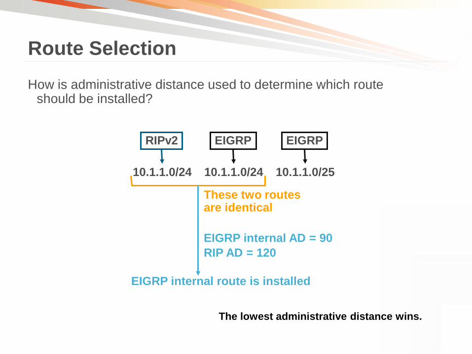
How is administrative distance used to determine which route should be installed?
Route Selection
10.1.1.0/24 10.1.1.0/25 10.1.1.0/24
EIGRP EIGRP RIPv2
These two routes are identical
EIGRP internal route is installed
EIGRP internal AD = 90 RIP AD = 120
The lowest administrative distance wins.

• Only identical routes are compared
• Identical prefixes with different prefix lengths are not the same route
• The route from the protocol with the lower administrative distance is installed
Route Selection

• What happens if the administrative distance of the two routes are equal?
• It depends on the routing protocol
Route Selection
10.1.1.0/24 10.1.1.0/25 10.1.1.0/24
EIGRP EIGRP RIPv2
These two routes are identical
EIGRP internal = 90 RIPv2 = Configured to 90
It depends. Usually the route with the default AD is installed into the RIB

OSPF and IS-IS
Route Selection
10.1.1.0/24 10.1.1.0/24
OSPF 2 AD=110
OSPF 1 AD=110
IS-IS default AD 115 OSPF default AD 110 OSPF wins
10.1.1.0/24
IS-IS AD=115
Default AD is the same between the two OSPF processes
The older route remains in the RIB

EIGRP
Route Selection
10.1.1.0/24 10.1.1.0/24
EIGRP 2 AD=90
Metric=500
EIGRP 1 AD=90
Metric=1000
EIGRP def. AD is 90 OSPF def. AD is 110 EIGRP wins
10.1.1.0/24
OSPF AD=110
EIGRP 2 route metric is lower than EIGRP 1
EIGRP 2 route is installed in the RIB
Tie breaker is the lowest AS number

Route Selection
• What happens if the same routing process has multiple identical routes with the same metric?
10.1.1.0/24 10.1.1.0/24
EIGRP 1 AD=90
Metric=500
EIGRP 1 AD=90
Metric=500
EIGRP def. AD is 90 OSPF def. AD is 110 EIGRP wins
Both routes have the same metric and the same AS number
BOTH routes are installed in the RIB
10.1.1.0/24
OSPF AD=110
When multiple paths exist within the same routing process with equal cost, both are presented to the RIB for equal cost load-sharing

© 2010 Cisco and/or its affiliates. All rights reserved. Cisco Public BRKARC-2350 29 © 2011 Cisco and/or its affiliates. All rights reserved. Cisco Confidential 29
The Routing Table: Interface Down Events
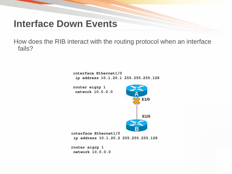
How does the RIB interact with the routing protocol when an interface fails?
Interface Down Events
interface Ethernet1/0 ip address 10.1.20.1 255.255.255.128 router eigrp 1 network 10.0.0.0
interface Ethernet1/0 ip address 10.1.20.2 255.255.255.128 router eigrp 1 network 10.0.0.0
A
B
E1/0
E1/0
Interface Down Events
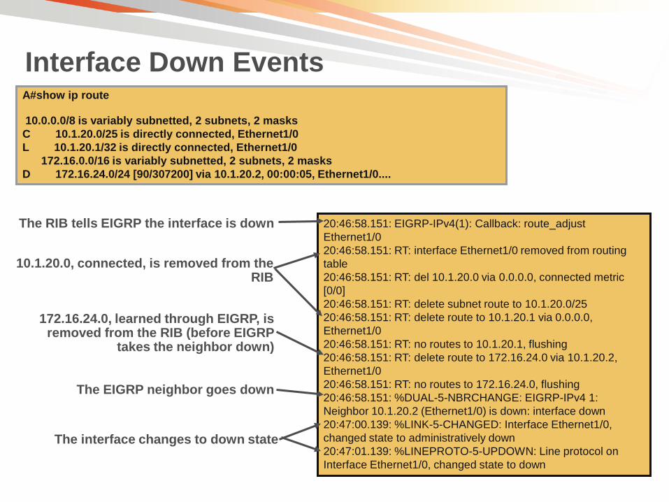
20:46:58.151: EIGRP-IPv4(1): Callback: route_adjust Ethernet1/0 20:46:58.151: RT: interface Ethernet1/0 removed from routing table 20:46:58.151: RT: del 10.1.20.0 via 0.0.0.0, connected metric [0/0] 20:46:58.151: RT: delete subnet route to 10.1.20.0/25 20:46:58.151: RT: delete route to 10.1.20.1 via 0.0.0.0, Ethernet1/0 20:46:58.151: RT: no routes to 10.1.20.1, flushing 20:46:58.151: RT: delete route to 172.16.24.0 via 10.1.20.2, Ethernet1/0 20:46:58.151: RT: no routes to 172.16.24.0, flushing 20:46:58.151: %DUAL-5-NBRCHANGE: EIGRP-IPv4 1: Neighbor 10.1.20.2 (Ethernet1/0) is down: interface down 20:47:00.139: %LINK-5-CHANGED: Interface Ethernet1/0, changed state to administratively down 20:47:01.139: %LINEPROTO-5-UPDOWN: Line protocol on Interface Ethernet1/0, changed state to down
The RIB tells EIGRP the interface is down
10.1.20.0, connected, is removed from the RIB
172.16.24.0, learned through EIGRP, is removed from the RIB (before EIGRP
takes the neighbor down)
The EIGRP neighbor goes down
The interface changes to down state
A#show ip route 10.0.0.0/8 is variably subnetted, 2 subnets, 2 masks C 10.1.20.0/25 is directly connected, Ethernet1/0 L 10.1.20.1/32 is directly connected, Ethernet1/0 172.16.0.0/16 is variably subnetted, 2 subnets, 2 masks D 172.16.24.0/24 [90/307200] via 10.1.20.2, 00:00:05, Ethernet1/0....

© 2010 Cisco and/or its affiliates. All rights reserved. Cisco Public BRKARC-2350 32 © 2011 Cisco and/or its affiliates. All rights reserved. Cisco Confidential 32
The Routing Table: Backup, Static, and Discard Routes

© 2010 Cisco and/or its affiliates. All rights reserved. Cisco Public BRKARC-2350 33 © 2011 Cisco and/or its affiliates. All rights reserved. Cisco Confidential 33
Backup Routes

Backup Routes
10.1.1.0/24 10.1.1.0/25 10.1.1.0/24
EIGRP EIGRP RIPv2
These two routes are identical
EIGRP internal installed
EIGRP internal AD = 90 RIP AD = 120
RIP route installed
RIB calls backups

• If a route with a low administrative distance fails…
• The routing table calls each routing process asking for backup routes
• Each routing process attempts to install its matching routes
• The route with the lowest administrative distance wins
Backup Routes

Backup Routes
router-b#show ip route Codes: D - EIGRP, EX - EIGRP external, O – OSPF.... .... O 10.0.16.0/24 [110/1064] via 10.0.12.10, Serial0/3
router-b#show ip eigrp topo IP-EIGRP Topology Table for AS(100)/ID(208.0.17.11) .... P 10.0.16.0/24, 0 successors, FD is Inaccessible
router-b#debug ip routing router-b#debug ip eigrp notifications .... RT: delete route to 10.0.16.0/24
IP-EIGRP: Callback: callbackup_routes 10.0.16.0/24
IP-EIGRP: Callback: reload_iptable
RT: add 10.0.16.0/24 via 10.0.12.10, eigrp metric [170/3072256]
router-b#show ip route Codes: D - EIGRP, EX - EIGRP external, O – OSPF.... .... D EX 10.0.16.0/24 [170/3072256] via 10.0.12.10, Serial0/3 ....
The route is installed by OSPF
EIGRP has the same route in its topology table, but it’s not installed because it has a higher AD (170)
The OSPF route fails…
EIGRP gets a callback for 10.0.16.0/24, which is the OSPF route that failed
EIGRP installs the existing 10.0.16.0/24 route from its topology table
The route is now installed by EIGRP

© 2011 Cisco and/or its affiliates. All rights reserved. Cisco Confidential 37
Static Routes
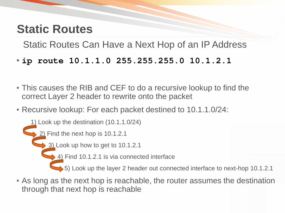
• ip route 10.1.1.0 255.255.255.0 10.1.2.1
• This causes the RIB and CEF to do a recursive lookup to find the correct Layer 2 header to rewrite onto the packet
• Recursive lookup: For each packet destined to 10.1.1.0/24: 1) Look up the destination (10.1.1.0/24)
2) Find the next hop is 10.1.2.1
3) Look up how to get to 10.1.2.1
4) Find 10.1.2.1 is via connected interface
5) Look up the layer 2 header out connected interface to next-hop 10.1.2.1
• As long as the next hop is reachable, the router assumes the destination through that next hop is reachable
Static Routes Static Routes Can Have a Next Hop of an IP Address

• ip route 10.1.1.0 255.255.255.0 serial0
• The RIB and forwarding tables point the route directly out the point-to-point interface
- No need to do a recursive lookup
• For each packet destined to 10.1.1.0/24, the Layer 2 rewrite header is set up to reach the other end of the point-to-point link
• Faster, less complicated lookup
• As long as the interface is up, the router assumes the destination is reachable through that interface
Static Routes Static Routes Can Have a Next Hop of a Point-to-Point Serial interface

• ip route 10.1.0.0 255.255.0.0 fa0/0
• The RIB and CEF will point this route directly to the broadcast
interface
router#show ip route .... 10.0.0.0/16 is subnetted, 1 subnets S 10.1.0.0 is directly connected, FastEthernet0/0
Static Routes Static Routes Can Have a Next Hop of a broadcast interface

Static Routes
ip route 0.0.0.0 0.0.0.0 FastEthernet 0/0
10.2.1.0/24 via internetwork
Packet to 10.2.1.25
Best route is through broadcast
interface FE0/0
ARP for 10.2.1.25
Route to 10.2.1.25 through
internetwork
ARP reply 10.2.1.25 via B
Send packets to 10.2.1.25 via B’s
MAC address
10.2.1.25
This happens for each destination in which host A does not have a route
Proxy ARP must be enabled
A B
Note: Proxy ARP disabled by default
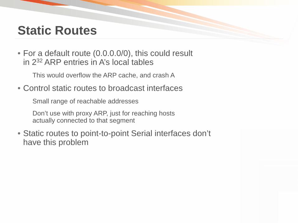
• For a default route (0.0.0.0/0), this could result in 232 ARP entries in A’s local tables
This would overflow the ARP cache, and crash A
• Control static routes to broadcast interfaces Small range of reachable addresses
Don’t use with proxy ARP, just for reaching hosts actually connected to that segment
• Static routes to point-to-point Serial interfaces don’t have this problem
Static Routes

• For a static route to an interface, the destination network is shown in the routing table as connected:
router(config)#ip route 10.1.0.0 255.255.0.0 fa 0/1
router#show ip route .... 10.0.0.0/16 is subnetted, 1 subnets S 10.1.0.0 is directly connected, FastEthernet0/1
• Static routes to interfaces will be included if you configure redistribute connected
• How do routing protocols handle this in relation to the network statement?
Static Routes

• OSPF: Static routes to interfaces are not advertised as a result of a network statement
• IS-IS: IS-IS doesn’t use network statements, so static routes to interfaces are not advertised without redistribution
• EIGRP: Static routes to interfaces are considered connected routes They will be picked up and advertised if they are contained within a network statement
• BGP: Static routes to interfaces are installed in the routing table They will be picked up and advertised if they match a network statement
Static Routes
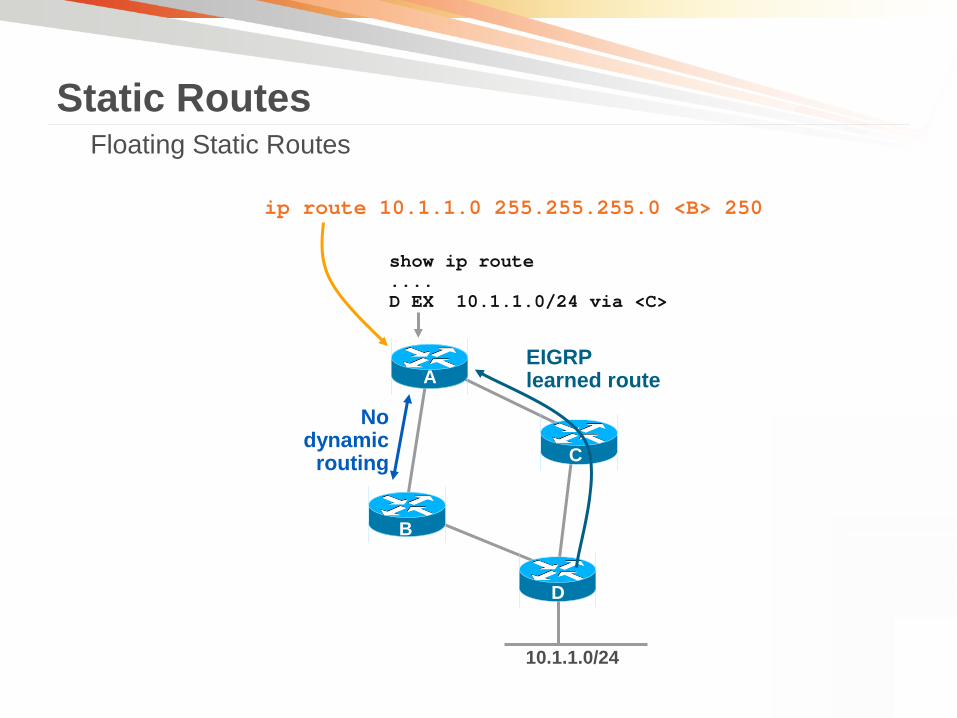
Floating Static Routes Static Routes
10.1.1.0/24
A
C
D
B
EIGRP learned route
No dynamic
routing
show ip route .... D EX 10.1.1.0/24 via <C>
ip route 10.1.1.0 255.255.255.0 <B> 250

• The concepts of administrative distance and backup routes are used to create floating static routes
• Configuring a static route with a very high administrative distance ensures it won’t be installed as long as there is a dynamically learned route installed in the RIB using the default AD
• 255 = unreachable
Static Routes

Static Routes
10.1.1.0/24
A
C
D
B
EIGRP learned route
No dynamic
routing
ip route 10.1.1.0 255.255.255.0 <B> 250
show ip ip route .... 10.1.1.0 via <C>
show ip route .... S 10.1.1.0 via <B>
Floating Static Routes

• When the dynamically learned route fails, the RIB calls the processes looking for a backup route
• Since no other processes have routes to install, the static route with an administrative distance of 250 wins
• This assumes that the primary route will be removed from the table in a failure event. If a failure event will not remove the primary route from the RIB then the floating static backup will not be installed.
Static Routes

How can we get dynamic failover with no dynamic routing?
Static Routing with Object Tracking
10.1.1.0/24
A
C
D
B
172.16.13.0/24
ip route 10.1.1.0 255.255.255.0 <B> 10
show ip route .... 10.1.1.0 via <C>
172.16.12.0/24
ip route 10.1.1.0 255.255.255.0 <C>
172.16.24.0/24
.2
.3

Static Routing with Object Tracking
02:34:12.106: ICMP: echo reply rcvd, src 172.16.24.2, dst 172.16.12.1, topology BASE, dscp 0 topoid 0 02:34:17.114: ICMP: dst (172.16.12.1) host unreachable rcv from 172.16.12.2 02:34:17.306: Track: 1 Change #9 ip sla 1, reachability Up->Down 02:34:17.306: %TRACKING-5-STATE: 1 ip sla 1 reachability Up->Down 02:34:17.306: RT: del 10.1.1.0 via 172.16.12.2, static metric [1/0] 02:34:17.306: RT: delete subnet route to 10.1.1.0/24 02:34:17.306: RT: updating static 10.1.1.0/24 (0x0) via 172.16.13.3 02:34:17.306: RT: add 10.1.1.0/24 via 172.16.13.3, static metric [10/0] 02:34:17.310: RT: updating static 10.1.1.0/24 (0x0) via 172.16.13.3 02:34:22.114: ICMP: dst (172.16.12.1) host unreachable rcv from 172.16.12.2
The track object goes down when reachability fails
Probes are still sent to determine when this path is available again
ip route 10.1.1.0 255.255.255.0 172.16.12.2 track 1 ip route 10.1.1.0 255.255.255.0 172.16.13.3 10 track 1 ip sla 1 reachability ip sla 1 icmp-echo 172.16.24.2 source-interface Ethernet1/0 frequency 5 ip sla schedule 1 life forever start-time now
Probes are being sent to 172.16.24.2
The routing table is updated to remove the route to the destination through the
tracked path
The floating static route is installed into the routing table

10.1.1.0/24
A
C
B
D
Connectivity is unstable. Any helpful tools?
We can use Embedded Event Manager (EEM) to notify us of the issue
event manager applet static_tracking event syslog pattern "%TRACKING-5-STATE: 1 ip sla 1 reachability Up->Down" action 1 wait 3 action 2 cli command "enable" action 3 cli command "term len 0" action 4 cli command "term exec prompt timestamp" action 5 cli command "show log | append flash:log_output" action 6 mail server "<mail_server_ip>" to "<email_address>" from "<sender>" subject “Link C-D is down." end
- Use EEM Object Tracking Tip
www.cisco.com/web/go/eem

• BFD – Bidirectional Forwarding Detection BFD builds its own neighbor relationship with adjacent routers to provide fast peer failure detection independent of media type, encapsulation, or routing protocols
• Static routing has no method of peer discovery Can use BFD to track the reachability of the peer
• Static route only installed in RIB if BFD session is up allowing us to consider the Gateway reachable
Static Routing with BFD
Interface GigabitEthernet0 ip address 2.2.2.1 255.255.255.252 bfd interval 500 min_rx 500 multiplier 5 ip route static bfd GigabitEthernet0 2.2.2.2 ip route 192.168.1.1 255.255.255.255 GigabitEthernet0 2.2.2.2
© 2011 Cisco and/or its affiliates. All rights reserved. Cisco Confidential 53
Discard Routes

•Discard routes are created when a router aggregates routing information
(EIGRP) ip summary-address eigrp 100 10.1.0.0 255.255.0.0 5
(OSPF) area 1 range 10.1.0.0 255.255.0.0
(IS-IS) summary-address 10.1.0.0 255.255.0.0 level-2
....
Router_A#show ip route
....
D 10.1.0.0/16 is a summary, 00:04:03, Null0
•A discard route has an administrative distance of five by default
Discard Routes

Why is this discard route created?
• Suppose A is advertising a default route to B B is advertising the summary 10.1.0.0/16 to A B is not building a discard route for this summary
Discard Routes
10.1.1.0/24
10.1
.3.0
/24 0.0.0.0/0
10.1.0.0/16 A
B
interface eth 0/0 ip summary-address eigrp 100 10.1.0.0 255.255.0.0 … ip route 0.0.0.0 0.0.0.0 <A>

A receives a packet for 10.1.3.1
Discard Routes
10.1.3.1 via 10.1.0.0/16
10.1.3.1 via 0.0.0.0/0
10.1.1.0/24
10.1
.3.0
/24
0.0.0.0/0
10.1.0.0/16 A
B
We have a permanent routing loop. Routing Loop avoided if B had a discard route for 10.1.0.0/16
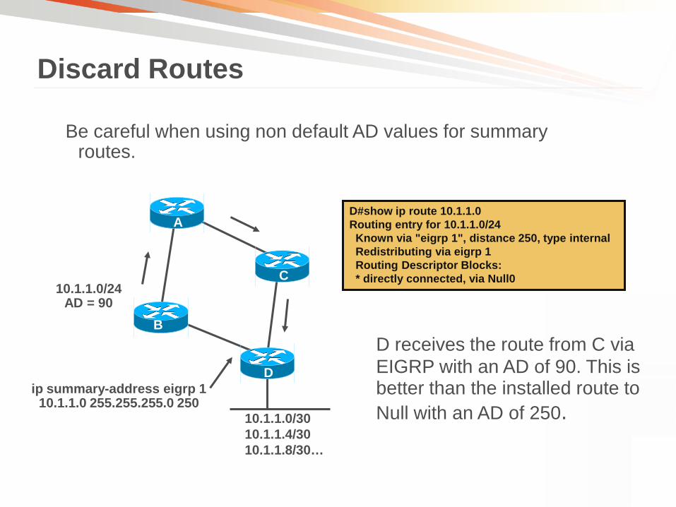
Be careful when using non default AD values for summary routes.
Discard Routes
10.1.1.0/30 10.1.1.4/30 10.1.1.8/30…
D
A
C
B
10.1.1.0/24 AD = 90
ip summary-address eigrp 1 10.1.1.0 255.255.255.0 250
D#show ip route 10.1.1.0 Routing entry for 10.1.1.0/24 Known via "eigrp 1", distance 250, type internal Redistributing via eigrp 1 Routing Descriptor Blocks: * directly connected, via Null0
D receives the route from C via EIGRP with an AD of 90. This is better than the installed route to Null with an AD of 250.

© 2010 Cisco and/or its affiliates. All rights reserved. Cisco Public BRKARC-2350 60 © 2011 Cisco and/or its affiliates. All rights reserved. Cisco Confidential 60
Overriding the Routing Table

What if I do not want to route my traffic based only on destination?
• Policy-Based Routing (PBR) Route-map
• Performance Routing (PfR) Source IP
ToS
Application
Link Utilization
Overriding the Routing Table

© 2010 Cisco and/or its affiliates. All rights reserved. Cisco Public BRKARC-2350 62 © 2011 Cisco and/or its affiliates. All rights reserved. Cisco Confidential 62
Overriding the Routing Table: Policy Based Routing

• Route maps allow you to: Combine more than one type of filter into a single phrase
Use some rudimentary forms of logical “AND” and “OR” to filter routes
Set some route attributes, rather than just permitting or denying routes
• Route maps can be used to: Set IP next-hop
Filter BGP updates
Filter EIGRP updates
Filter routes being redistributed between two protocols
Etc.
Route Maps

Route Maps
route-map CMUG permit 10 match ip address 10 route-map CMUG permit 20 match ip address 20 set ip next-hop 10.1.1.1 route-map CMUG permit 30 set ip next-hop 10.2.2.2
Type of phrase (permit or deny) Phrase sequence
Phrase 1
Phrase 2
Phrase 3
One of the two results of a route map is whether the route is permitted or denied
through the filter
If this match succeeds, the route map exits with permit
If not, the route map continues with the next phrase
If this match succeeds, set next-hop is executed, and the route map exits with permit
If not, the route map continues with the next phrase
If the route map makes it to this phrase, set next-hop is executed, and the route map exits with permit

Route Maps
Phrase type
Match result
Route map result
Permit Permit Set statements within the phrase are executed and the route map exits with permit
Deny Permit Set statements within the phrase are not executed and the route map exits with deny
Permit/ Deny
Deny Set statements within the phrase are not executed and route map continues with the next phrase If there is no next phrase, route map exits with deny

• PBR proceeds through the route map until a match is found. If no match is found in the route map, the packet will be forwarded according to normal destination-based routing
• If the route-map statement is marked as a deny, the packets meeting the match criteria are forwarded according to normal destination-based routing
• If the statement is marked as permit and the packets do not meet the match criteria, the packets are forwarded according to normal destination- based routing
• If the route-map statement is marked as permit and the packets meet the match criteria, the set clauses are applied and policy routing is performed
Route Maps

Route Maps Match Description
metric Metric of the route In BGP’s case, this is the MED Must match exactly!
route-type OSPF or EIGRP route type Internal, External OSPF external type 1 or 2
tag Route tag
ip address Standard or extended access list Applied against the prefix Numbered or named
ip address prefix-list Prefix list Applied against the prefix and prefix length
ip next-hop Standard or extended access list Applied against the next hop (via in the routing table) Numbered or named
length Packet length
ip route-source Standard or extended access list Applied against the neighbor this route was learned from (from in the routing table) Numbered or named

• Not all set statements work with all protocols or in all situations
• It is recommended to test what you want to do before you try to use it
Route Maps
Set Description ip next-hop Set the next hop in the routing table or transmitted route ip next-hop recursive Set the next hop to a subnet which is not directly connected ip next-hop verify Set the next hop and verify availability using tracking interface Set the output interface metric Set the metric of the redistributed or transmitted route metric-type Set the type of external route
External type 1 or type 2 for OSPF tag Sets the route tag

Route Map Logic (AND)
route-map CMUG permit 10 match ip address 10 match tag 1000 set ip next-hop 10.1.1.1
Must match BOTH ‘match’ conditions to successfully match route-map phrase
Logical AND
Some types of matches cannot co-exist in the same route map phrase, such as an access list and a prefix list

Route Map Logic (OR)
route-map CMUG permit 10 match ip address 10 20 set ip next-hop 10.1.1.1
Can match any ACL in the ACL list under the single ‘match’ statement
Logical OR

Route Map Logic (NOT)
route-map CMUG permit 10 match ip address 10 route-map CMUG permit 20 match ip address 20 route-map CMUG permit 30 set ip next-hop 10.1.1.1
If we match either ACL in phrase 10 or phrase 20 then we exit the route-map and don’t fall to catch-all phrase 30. Therefore we must NOT match either ACL 10 nor 20 in order for the ‘set’ to apply
Logical NOT
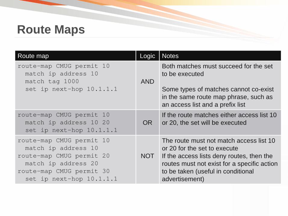
Route Maps
Route map Logic Notes route-map CMUG permit 10 match ip address 10 match tag 1000 set ip next-hop 10.1.1.1
AND
Both matches must succeed for the set to be executed Some types of matches cannot co-exist in the same route map phrase, such as an access list and a prefix list
route-map CMUG permit 10 match ip address 10 20 set ip next-hop 10.1.1.1
OR
If the route matches either access list 10 or 20, the set will be executed
route-map CMUG permit 10 match ip address 10 route-map CMUG permit 20 match ip address 20 route-map CMUG permit 30 set ip next-hop 10.1.1.1
NOT
The route must not match access list 10 or 20 for the set to execute If the access lists deny routes, then the routes must not exist for a specific action to be taken (useful in conditional advertisement)

• In normal processing, if all matches fail, the route map falls through to the next phrase
• Route map continue allows you to continue to another phrase if the matches succeed
• Sets are executed before the continue is followed
• Use for: Gathering policy (matches and sets) into a single phrase
More complex logical constructions
Route Maps

Route Maps
route-map CMUG permit 10 match ip address 10 set ip next-hop 10.1.1.1 continue 30 route-map CMUG permit 20 match ip address 20 set ip next-hop 10.1.2.1 continue 30 route-map CMUG permit 30 set ip precedence critical set ip df 0
If this match succeeds
Execute this set
Continue to 30
Execute this set If this match succeeds
Execute this set
Continue to 30
Execute this set
Gathering Policy with Continue

Policy Based Routing
10.1.3.0/24
B
D
E
C
Router_B#show ip route .... D 10.1.3.0/24 via <E> Router_B#show run interface Ethernet1/0 ip policy route-map CMUG access-list 10 permit 1.1.1.0 0.0.0.255 access-list 20 permit 1.1.2.0 0.0.0.255 route-map CMUG permit 10 match ip address 10 route-map CMUG permit 20 match ip address 20 set ip next-hop 10.1.1.2 route-map CMUG permit 30 set ip next-hop 10.2.2.2
A
1.1.1.0/24
1.1.2.0/24
10.1.1.0/24
10.2.2.0/24
E1/0
.2
.1 .2
.1

• PBR applied to an interface only affects traffic that comes in that interface
• Can configure a PBR policy local to the router
• Local PBR policy only affects traffic generated from the router itself
Policy Based Routing
Router#show run ip local policy route-map CMUG access-list 101 permit ip any 1.1.1.0 0.0.0.255 route-map CMUG permit 10 match ip address 101 set ip next-hop 10.1.1.2

• Can PBR be Dynamic? You can use Object Tracking with PBR to track the availability of the next-hop
Policy Based Routing
track 1 ip sla 1 reachability track 2 ip sla 2 reachability ip sla 1 icmp-echo 10.10.10.2 source-interface Ethernet1/0 ip sla 2 icmp-echo 10.10.10.3 source-interface Ethernet1/0 ip sla schedule 1 life forever start-time now ip sla schedule 2 life forever start-time now route-map CMUG permit 10 match ip address 101 set ip next-hop verify-availability 10.10.10.2 1 track 1 set ip next-hop verify-availability 10.10.10.3 2 track 2
Sequence number determines priority of next-hops
•Tracking object tied to IP SLA object
•Route-map ties next-hop to tracking object so next-hop is only valid if the tracking object is UP
•If both tracking objects are DOWN, normal routing is used

• Load sharing—Supplemental to dynamic load-sharing capabilities offered by Cisco IOS, PBR allows traffic to be administratively distributed among multiple paths based on the traffic characteristics
• Quality of Service (QoS)—Using IP Precedence or type of service (ToS) values to prioritize differentiated traffic
• Source-sensitive routing—Route traffic originating from different users through different paths
• Cost—Route traffic across low-bandwidth, low-cost permanent paths or high-bandwidth, high-cost, switched paths
• Security—Route certain types of traffic (like http) to firewall/IPS/content filtering device and allow other traffic to follow normal routing
Policy Based Routing

© 2011 Cisco and/or its affiliates. All rights reserved. Cisco Confidential 81
Overriding the Routing Table: Performance Routing

• Traditional routing based on destination of packet
• Policy-based routing allows routing based on more information about the packet
Source IP, Protocol, Ports Used, QoS markings, etc
• Performance Routing (PFR) allows for routed path decisions to be made on path characteristics (like reachability, delay, packet loss, jitter, Mean opinion Score) so application traffic can be given the optimum path given it’s path requirements
Performance Routing
www.cisco.com/go/pfr

Performance Routing Learn traffic and applications
Discovers traffic going through network via Netflow
Measure traffic and application performance Tracks characteristics like loss/delay/jitter about paths either
passively (via netflow) or actively (via IP SLA probes)
Apply policies to the traffic based on measurements Allows definitions of policies so certain applications or traffic classes
given required network service
Reroute traffic Dynamically alters path of application traffic if current service not in
line with specified policy to sustain performance
www.cisco.com/go/pfr

Performance Routing
Enterprise
MC
BR
BR
ISP1
ISP2
Border Routers collect traffic information and pass the information to a central router (called a Master Controller)
Master Controller receives information about flows and determine if they are within configured policy for traffic class
If measurements of traffic class is out of policy or less-optimum, Master controller can send commands to the borders to re-route traffic
Information
Information
Command
Voice
Apps
Internet
www.cisco.com/go/pfr

© 2010 Cisco and/or its affiliates. All rights reserved. Cisco Public BRKARC-2350 85 © 2011 Cisco and/or its affiliates. All rights reserved. Cisco Confidential 85
Load Sharing

• Assume the same routing process attempts to install two routes for the same destination in the RIB
• The routing process may allow the second route to be installed based on its own rules
Load Sharing
OSPF IS-IS EIGRP Route cost Must be equal to
installed route Must be equal to installed route
Must be less than or equal to the lowest cost route times the variance
Maximum Paths Must be less than or equal to the maximum-paths configured under the routing process

• Per-session (Per-destination)
• Per-packet
Load Sharing Load sharing performed in the CEF (Cisco Express Forwarding) path CEF has 2 forms of load sharing
Flow 1 - Flow 2 -
Eth1 – Eth2 –
Eth1 – Eth2 –

• Often referred to as per-destination load sharing, even within Cisco IOS
• This method is the default behavior and does not require any additional configuration
• A session is a flow that shares the same source and destination. Traffic with different source to destination pairs tend to take different paths
• This method ensures that traffic for a given session arrive in order
• Has the potential for traffic polarization and is more effective as the number of source to destination pairs increase
Load Sharing Per-Session Load Sharing

• To utilize this method, configure “ip cef load-sharing per-packet” in interface configuration mode. Each outgoing interface must have this command configured
• Uses a round-robin method to determine which path each packet takes to the destination without consideration of source to destination sessions
• Ensures traffic is more evenly distributed over multiple paths
• Packets for a given source to destination session may take different paths, introducing a greater potential for packets to arrive out of sequence. Not advisable for all types of traffic
• Method used when process-switching
Load Sharing Per-Packet Load Sharing

Load Sharing
router#show ip route 192.168.239.0 Routing entry for 192.168.239.0/24 Known via "eigrp 100", distance 170, metric 3072256, type external Redistributing via eigrp 100 Last update from 192.168.245.11 on Serial3/1, 00:18:17 ago Routing Descriptor Blocks: * 192.168.246.10, from 192.168.246.10, 00:18:17 ago, via Serial3/0 Route metric is 3072256, traffic share count is 1 .... 192.168.245.11, from 192.168.245.11, 00:18:17 ago, via Serial3/1 Route metric is 3072256, traffic share count is 1 ....
The traffic share count is critical to understanding the actual load sharing of packets using these two routes
How is this calculated?

Load Sharing
router#show ip route 192.168.239.0 Routing entry for 192.168.239.0/24 Known via "eigrp 100", distance 170, metric 3072256, type external Redistributing via eigrp 100 Last update from 192.168.245.11 on Serial3/1, 00:18:17 ago Routing Descriptor Blocks: * 192.168.246.10, from 192.168.246.10, 00:18:17 ago, via Serial3/0 Route metric is 3072256, traffic share count is 1 .... 192.168.245.11, from 192.168.245.11, 00:18:17 ago, via Serial3/1 Route metric is 3072256, traffic share count is 1 ....
The metric of each route is divided into the highest metric among the available metrics
3072256/3072256 == 1
The resulting number is the traffic share count

Load Sharing
router#show ip route 192.168.239.0 Routing entry for 192.168.239.0/24 Known via "eigrp 100", distance 170, metric 3072256, type external Redistributing via eigrp 100 Last update from 192.168.245.11 on Serial3/1, 00:18:17 ago Routing Descriptor Blocks: * 192.168.246.10, from 192.168.246.10, 00:18:17 ago, via Serial3/0 Route metric is 1536128, traffic share count is 2 .... 192.168.245.11, from 192.168.245.11, 00:18:17 ago, via Serial3/1 Route metric is 3072256, traffic share count is 1 ....
If one metric is less than another metric, the traffic share count will be something other than 1 (only for EIGRP and requires variance to be configured) 3072256/3072256 == 1
The resulting number is the traffic share count 3072256/1536128 == 2

Load Sharing
router#show ip route 192.168.239.0 Routing entry for 192.168.239.0/24 Known via "eigrp 100", distance 170, metric 3072256, type external Redistributing via eigrp 100 Last update from 192.168.245.11 on Serial3/1, 00:18:17 ago Routing Descriptor Blocks: * 192.168.246.10, from 192.168.246.10, 00:18:17 ago, via Serial3/0 Route metric is 3072256, traffic share count is 1 .... 192.168.245.11, from 192.168.245.11, 00:18:17 ago, via Serial3/1 Route metric is 3072256, traffic share count is 1 ....
When process switching, traffic share count packets is sent down one path, and then the process moves to the next available path
The route with the * beside it is the current in use path for process-switching

Load Sharing
CEF uses 16 hash buckets and assigns hash buckets to each next-hop
Router#sh ip cef 1.1.1.3 internal
[snip]
1.1.1.3/32, epoch 0, RIB[I], refcount 5, per-destination sharing
Ethernet1/0(7): 10.3.3.1, 10.3.3.2
nexthop 10.3.3.1 Ethernet1/0, adjacency IP adj out of Ethernet1/0, addr 10.3.3.1
nexthop 10.3.3.2 Ethernet1/0, adjacency IP adj out of Ethernet1/0, addr 10.3.3.2
flags: Per-session, for-rx-IPv4
16 hash buckets
< 0 > IP adj out of Ethernet1/0, addr 10.3.3.1 044C4608
< 1 > IP adj out of Ethernet1/0, addr 10.3.3.2 044C44E8
< 2 > IP adj out of Ethernet1/0, addr 10.3.3.1 044C4608
< 3 > IP adj out of Ethernet1/0, addr 10.3.3.2 044C44E8
< 4 > IP adj out of Ethernet1/0, addr 10.3.3.1 044C4608
< 5 > IP adj out of Ethernet1/0, addr 10.3.3.2 044C44E8
< 6 > IP adj out of Ethernet1/0, addr 10.3.3.1 044C4608
< 7 > IP adj out of Ethernet1/0, addr 10.3.3.2 044C44E8
< 8 > IP adj out of Ethernet1/0, addr 10.3.3.1 044C4608
< 9 > IP adj out of Ethernet1/0, addr 10.3.3.2 044C44E8
<10 > IP adj out of Ethernet1/0, addr 10.3.3.1 044C4608
<11 > IP adj out of Ethernet1/0, addr 10.3.3.2 044C44E8
<12 > IP adj out of Ethernet1/0, addr 10.3.3.1 044C4608
<13 > IP adj out of Ethernet1/0, addr 10.3.3.2 044C44E8
<14 > IP adj out of Ethernet1/0, addr 10.3.3.1 044C4608
<15 > IP adj out of Ethernet1/0, addr 10.3.3.2 044C44E8
Router#sh ip route 1.1.1.3
Routing entry for 1.1.1.3/32
Known via "ospf 10", distance 110, metric 20, type extern 2, forward metric 30
Last update from 10.3.3.2 on Ethernet1/0, 00:01:04 ago
Routing Descriptor Blocks:
10.3.3.2, from 70.70.70.70, 00:01:04 ago, via Ethernet1/0
Route metric is 20, traffic share count is 1
* 10.3.3.1, from 70.70.70.70, 00:01:24 ago, via Ethernet1/0
Route metric is 20, traffic share count is 1
Each packet that comes in gets measured against the HASH, and the HASH result determines which hash bucket the packet uses
Each next-hop has 8 hash buckets The result is a 50/50 chance of getting each next-hop 1:1 load-sharing

Load Sharing
Per-destination Load-sharing takes a set of inputs, runs those inputs into the hash algorithm, and the result of the algorithm determines which load-sharing Hash bucket that packet will use Per-destination load-sharing algorithm used will determine which inputs are put into the hash
Hash
. 6 5 4 3 2 1
via Serial3/0
via Serial3/1 Hash Result
Hash Inputs

Load Sharing
CEF hashes the source and destination addresses, and chooses a bucket from the load share table
Source 10.1.1.1 Destination 192.168.239.1 Hash
. 6 5 4 3 2 1
The load share table points to an adjacency corresponding to one of the next hops in the routing table
via Serial3/0
via Serial3/1
= 5 Hash Result

Load Sharing
router#show ip cef exact-route 10.1.1.1 192.168.239.1 10.1.1.1 -> 192.168.239.1 : Serial3/0 (next hop 192.168.246.10)
• How do I tell which next-hop a particular packet will take?
•‘exact-route’ command in CEF takes hash inputs (source/destination IP) and puts them through the hash to result the egress interface
•Useful in tracing path of packet during troubleshooting

Load Sharing
If the hash for packet 1 always results in path 1 And if the hash for packet 2 always results in path 2
If the same input into the hash algorithm produces the same result, then what if there are many routers using the same algorithm?
A
B
C
D
E
F
Packet 1 = src 1.1.1.1 dst 2.2.2.2 Packet 2 = src 1.1.1.1 dst 3.3.3.3
G
1 2
1
1
2
2
Then all routers will make the same path decision and as a result the links between B=>E and C=>F will never be used!
Polarization

Load Sharing
We can fix this if we change the inputs on each router by looking at something else besides just the src/dst IP
-But this extra input would need to be unique per router, otherwise every router will pick the same path again
A
B
C
D
E
F
G
1 2
1
1
2
2
Universal Algorithm Each router adds a unique random number to the hash algorithm resulting in the possibility that the hash result on each hop may be different
Polarization

Load Sharing
GW2
ISP1
Internet
ISP2
In addition to load sharing traffic based on application policies, PfR can also load share or load balance traffic based on link utilization.
Voice
Apps
Performance Routing
60%
Enterprise
Routing Updates
Routing Updates
GW1
20%
CORE
www.cisco.com/go/pfr

Load Sharing
Enterprise
MC
BR
BR
ISP1
Internet
ISP2
CE2 link was 60% utilized and CE1 only 20%. PfR can identify this and move traffic to better balance out the egress link utilizations. Done by configuring a policy to keep link utilization within a % of
each other, so one link isn’t utilized more than the other
Information
Information
Command
Voice
Apps
Performance Routing
39%
41%
www.cisco.com/go/pfr

© 2011 Cisco and/or its affiliates. All rights reserved. Cisco Confidential 103
Routing Segmentation and Separation

• When would you want to separate routing operations? Prevent any potential exchange of data or routing information.
• Why not use ACLs or other security features? Helpful but limited
• A VRF can help prevent the exchange of routes as well as data and does not have to be constantly updated.
Routing Segmentation and Separation

What is a VRF?
• A VPN Routing and Forwarding (VRF) is an IOS routing instance. All tables (routing/cef) maintained in routing instance (vrf)
All protocols/features run independently in each VRF instance
Allows for logical separation at Layer-3
• Originally designed for MPLS VPN so multiple MPLS customers can use overlapping IP space and be logically separated from each other
This presentation will be referring to VRF outside of an MPLS VPN context. Also known as VRF-Lite.
Routing Segmentation and Separation

Routing Segmentation and Separation
Router_A
Router_A#show run vrf blue ip vrf blue ! ! interface Ethernet0/1 ip vrf forwarding blue ip address 172.16.12.1 255.255.255.0 ! interface Loopback1 ip vrf forwarding blue ip address 1.1.1.1 255.255.255.255 ! router eigrp 1 ! address-family ipv4 vrf blue network 172.16.12.0 0.0.0.255 no auto-summary autonomous-system 1 exit-address-family !
Router_A#show run vrf red ip vrf red ! ! interface Ethernet0/2 ip vrf forwarding red ip address 172.16.12.1 255.255.255.0 ! interface Loopback2 ip vrf forwarding red ip address 2.2.2.2 255.255.255.255 ! router eigrp 1 ! address-family ipv4 vrf red network 172.16.12.0 0.0.0.255 no auto-summary autonomous-system 1 exit-address-family !

Routing Segmentation and Separation How to configure and identify a VRF
Router#show ip vrf Name Default RD Interfaces blue <not set> Et0/1 Lo1 red <not set> Et0/2 Lo2 Router#show ip vrf int Interface IP-Address VRF Protocol Et0/1 172.16.12.1 blue up Lo1 1.1.1.1 blue up Et0/2 172.16.12.1 red up Lo2 2.2.2.2 red up Router#show ip route vrf blue Routing Table: blue 1.0.0.0/32 is subnetted, 1 subnets C 1.1.1.1 is directly connected, Loopback1 172.16.0.0/16 is variably subnetted, 2 subnets, 2 masks C 172.16.12.0/24 is directly connected, Ethernet0/1 L 172.16.12.1/32 is directly connected, Ethernet0/1

• Routing principles are the same within a VRF as in the global routing table.
• All routes and prefixes are unique to a given VRF unless route leaking is configured.
• Features that affect forwarding (like Routing Protocols/static routes/NAT/PBR) need to be configured on a per-VRF basis
• Interface-level features that affect traffic (like ACLs/QoS/uRPF) do not need to be configured to be VRF aware because they inherit the VRF of the interface on which they are configured
Routing Segmentation and Separation

© 2011 Cisco and/or its affiliates. All rights reserved. Cisco Confidential 109
Routing and Router Resources: CPU

• Central Processing Unit responsible for carrying out instructions.
• IOS uses a priority run-to-completion model for executing processes.
• The task scheduler is responsible for scheduling and executing kernel processes on the CPU
• Process Priorities: Critical High Medium Low
• There is no preemption but higher priority processes have more opportunity to access the CPU.
CPU

•What uses CPU resources? Router processes Packet switching
IP Input – Process switched packets
Interrupts – CEF switched packets
CPU
CPU utilization for five seconds: 5%/2%; one minute: 3%; five minutes: 2% PID Runtime (ms) Invoked uSecs 5Sec 1Min 5Min TTY Process [snip] 2 68 585 116 1.00% 1.00% 0% 0 IP Input 17 88 4232 20 0.20% 1.00% 0% 0 BGP Router 18 152 14650 10 0% 0% 0% 0 BGP Scanner

How does routing information affect CPU resources?
• BGP router calculates the best BGP path and processes any route "churn". It also sends and receives routes, establishes peers, and interacts with the routing information base (RIB).
• Does a large amount of work during initial convergence where large amount of prefixes are exchanged.
• The larger the tables that are being exchanged, the more time BGP router will have to use the CPU.
CPU

Monitoring CPU usage
• Show commands: show process cpu sorted
show process cpu history
• CPU threshold monitoring/logging process cpu threshold type {total | process | interrupt} rising percentage
interval seconds [falling percentage interval seconds]
CPU
18:41:20.934: %SYS-1-CPURISINGTHRESHOLD: Threshold: Total CPU Utilization(Total/Intr): 72%/0%, Top 3 processes(Pid/Util): 79/64%, 140/6%, 75/1%

• Reporting CPU events via EEM
CPU
event manager applet highcpu event snmp oid 1.3.6.1.4.1.9.9.109.1.1.1.1.3.1 get-type exact entry-op ge entry-val 90 poll-interval 10 action 1.0 cli command "enable" action 2.0 cli command "show proc cpu sorted | redirect flash:highcpu.txt“ action 3.0 syslog msg “High CPU DETECTED "show process cpu sort" written to > flash:highcpu.txt “ action 4.0 mail server "<mail_server_ip>" to "<email_address>" from "<sender>" subject “CPU exceeded 90%."
Event manager applet monitoring SNMP OID for CPU utilization percentage every 10 seconds Actual OID will depend on platform/code
If CPU OID value exceeds value 90 (90%), script will trigger the specified actions
www.cisco.com/web/go/eem

© 2011 Cisco and/or its affiliates. All rights reserved. Cisco Confidential 116
Routing and Router Resources: Memory

• Managed in 2 pools: Processor and I/O
• The processor memory pool is the general memory pool common to all IOS systems including storage for routing information.
• The I/O pool or packet memory manages memory for interface packet buffers.
Memory

How does routing information affect memory resources?
• Most common example of where we see this is the storing of BGP prefixes.
• BGP generally carries the largest number of prefixes as well as the potential to store multiple tables.
Memory

• How much memory do I need to store my routing information? Full BGP table
Multiple feeds
Route filtering
Soft reconfiguration inbound
Default route
Memory
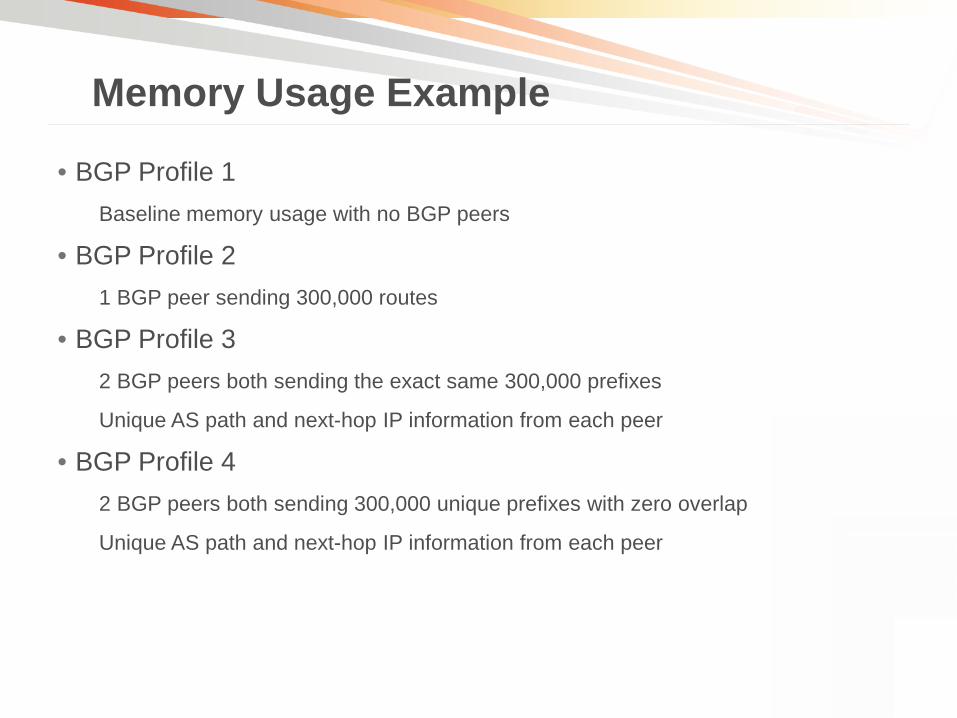
• BGP Profile 1 Baseline memory usage with no BGP peers
• BGP Profile 2 1 BGP peer sending 300,000 routes
• BGP Profile 3 2 BGP peers both sending the exact same 300,000 prefixes
Unique AS path and next-hop IP information from each peer
• BGP Profile 4 2 BGP peers both sending 300,000 unique prefixes with zero overlap
Unique AS path and next-hop IP information from each peer
Memory Usage Example

Memory Usage Example
#Peers #Routes Memory
1 0 0 27.5MB
2 1 300,000 221.2MB
3 2 600,000 245.1MB
4 2 600,000 416.1MB
BGP Routes vs. Memory Consumption
No Routes 300000 Routes
600000Routes
600000Routes
0
100000000
200000000
300000000
400000000
500000000
600000000
700000000
800000000
900000000
1000000000
1 2 3 4
BGP Profile
Tota
l Mem
ory
(Byt
es)
Free
Used
The amount of memory used to store prefixes also depends on the amount of overlap between peers.
BG
P P
rofil
e

Monitoring memory availability
• Show commands show process memory sorted
show memory statistics history
• Memory Threshold Notifications memory free low-watermark {processor threshold | io threshold}
memory reserve critical kilobytes
Memory
22:31:19.559: %SYS-4-FREEMEMLOW: Free Memory has dropped below 2000k Pool: Processor Free: 66814056 freemem_lwm: 204800000

© 2011 Cisco and/or its affiliates. All rights reserved. Cisco Confidential 123
Q & A