round Bale Wrapper Rb 580 - White's Inc · 1 For safe and proper functioning please: 1. Read the...
76
#404611-2 Round Bale Wrapper RB 580 Operator’s Manual 2011
Transcript of round Bale Wrapper Rb 580 - White's Inc · 1 For safe and proper functioning please: 1. Read the...

#404611-2
Round Bale Wrapper RB 580
Operator’s Manual2011


1
For safe and proper functioning please:
1. Read the manual. 2. Follow the safety instructions. 3. Follow the start-up steps given on the last page
of your manual.
4. In case of sale or transfer, give this manual to the new owner.
The illustrations in this manual are presented for your reference according to the latest information available at the moment of printing. ANDERSON EQUIPMENT reserves the right to modify its machines without advance notice.
2
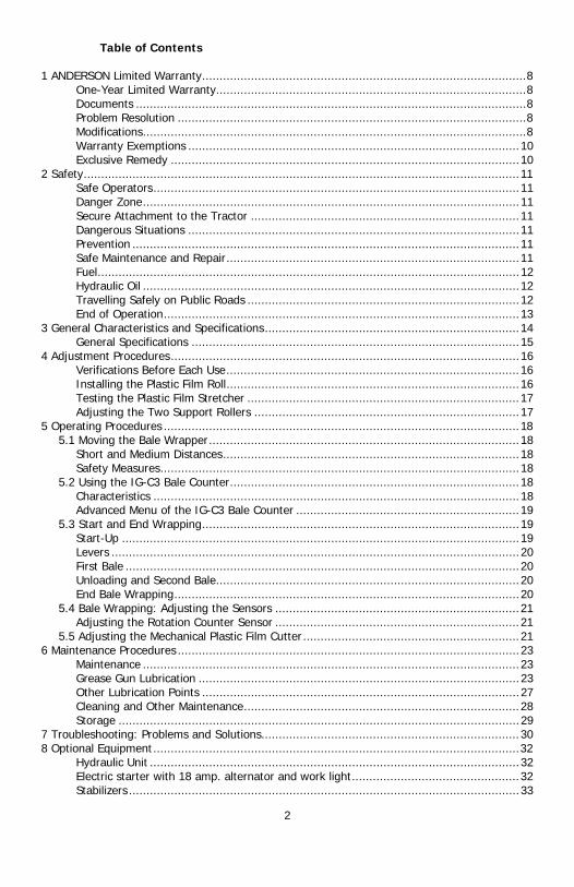
Table of Contents
1 ANDERSON Limited Warranty ............................................................................................. 8 One-Year Limited Warranty ......................................................................................... 8 Documents ................................................................................................................ 8 Problem Resolution .................................................................................................... 8 Modifications .............................................................................................................. 8 Warranty Exemptions ............................................................................................... 10 Exclusive Remedy .................................................................................................... 10
2 Safety ............................................................................................................................. 11 Safe Operators ......................................................................................................... 11 Danger Zone ............................................................................................................ 11 Secure Attachment to the Tractor ............................................................................. 11 Dangerous Situations ............................................................................................... 11 Prevention ............................................................................................................... 11 Safe Maintenance and Repair .................................................................................... 11 Fuel ......................................................................................................................... 12 Hydraulic Oil ............................................................................................................ 12 Travelling Safely on Public Roads .............................................................................. 12 End of Operation ...................................................................................................... 13
3 General Characteristics and Specifications ......................................................................... 14 General Specifications .............................................................................................. 15
4 Adjustment Procedures .................................................................................................... 16 Verifications Before Each Use .................................................................................... 16 Installing the Plastic Film Roll .................................................................................... 16 Testing the Plastic Film Stretcher .............................................................................. 17 Adjusting the Two Support Rollers ............................................................................ 17
5 Operating Procedures ...................................................................................................... 18 5.1 Moving the Bale Wrapper ......................................................................................... 18
Short and Medium Distances ..................................................................................... 18 Safety Measures ....................................................................................................... 18
5.2 Using the IG-C3 Bale Counter ................................................................................... 18 Characteristics ......................................................................................................... 18 Advanced Menu of the IG-C3 Bale Counter ................................................................ 19
5.3 Start and End Wrapping ........................................................................................... 19 Start-Up .................................................................................................................. 19 Levers ..................................................................................................................... 20 First Bale ................................................................................................................. 20 Unloading and Second Bale ....................................................................................... 20 End Bale Wrapping ................................................................................................... 20
5.4 Bale Wrapping: Adjusting the Sensors ...................................................................... 21 Adjusting the Rotation Counter Sensor ...................................................................... 21
5.5 Adjusting the Mechanical Plastic Film Cutter .............................................................. 21 6 Maintenance Procedures .................................................................................................. 23
Maintenance ............................................................................................................ 23 Grease Gun Lubrication ............................................................................................ 23 Other Lubrication Points ........................................................................................... 27 Cleaning and Other Maintenance ............................................................................... 28 Storage ................................................................................................................... 29
7 Troubleshooting: Problems and Solutions .......................................................................... 30 8 Optional Equipment ......................................................................................................... 32
Hydraulic Unit .......................................................................................................... 32 Electric starter with 18 amp. alternator and work light ................................................ 32 Stabilizers ................................................................................................................ 33

3
Modifying Gears to Reduce Stretch Ratio ................................................................... 33 Bale Loading Arm and Film Roll Support .................................................................... 33 Bale Unloading Platform (D)...................................................................................... 34 Unloading Platform (D3) ........................................................................................... 35 Double Roll Plastic Unit ............................................................................................. 39
9 Start-Up Procedures ........................................................................................................ 40
List of Illustrations
Figure 2.1 Lock of the turntable ........................................................................................ 12 Figure 2.2 Closing the fuel valve ....................................................................................... 13 Figure 3.1 Components of the wrapper .............................................................................. 14 Figure 3.2 Exterior dimensions for the base model ............................................................. 15 Figure 3.3 Exterior dimensions for model with optional ....................................................... 15 Figure 4.1 Installing the film roll ........................................................................................ 16 Figure 4.2 Direction of film unwinding ............................................................................... 17 Figure 4.3 Adjusting the support rollers ............................................................................. 17 Figure 5.1 Bale counter screen .......................................................................................... 18 Figure 5.2 580 Levers ....................................................................................................... 20 Figure 5.3 Rotation counter sensor .................................................................................... 21 Figure 5.4 Plastic film cutter blade..................................................................................... 21 Figure 5.5 Stopper spring and adjustment bolt ................................................................... 22 Figure 5.6 Adjusting the plastic film cutter blade (at rest) ................................................... 22 Figure 6.1 Grease gun lubrication ...................................................................................... 23 Figure 6.2 Lubricating the plastic film stretcher .................................................................. 27 Figure 6.3 Lubricating the chain (through the hole in the guard) ......................................... 27 Figure 6.4 Lubricating the plastic film cutter 1 .................................................................... 28 Figure 6.5 Lubricating the plastic film cutter 2 .................................................................... 28 Figure 7.1 Starter fuse ...................................................................................................... 31 Figure 8.1 Hydraulic unit and work light ............................................................................ 32 Figure 8.2 Stabilizers ........................................................................................................ 33 Figure 8.3 Bale loading arm .............................................................................................. 34 Figure 8.4 Bale unloading platform D ................................................................................ 34 Figure 8.5 Bale unloading platform D3 ............................................................................... 35 Figure 8.6 Accumulator of the unloading arm ..................................................................... 39 Figure 8.7 Double roll unit ................................................................................................ 39

4
How to Reach Us When you contact us, always provide us with the following information:
- Your name, address, and telephone number;
- Product model and serial number;
- Purchase date and invoice number;
- Dealer name, address, and telephone number and salesperson name;
- Precise and detailed description of your problem.
Address: ANDERSON EQUIPMENT 5125 de la Plaisance Chesterville (Québec) CANADA G0P 1J0
Email Service: [email protected]
Fax Service: 1-819-382-2218
Website: www.anderson-equipment.com

5
ANDERSON LIMITED WARRANTY
Warranty form must be completed and returned. Please fill in this form with information about your new machine. Please return this form to us in the 15 days following the date of delivery to validate your warranty. Details of the warranty provided can be found in the operator’s manual. Warranty Validation (to be mailed or faxed within 15 days)
Type of Machine:
Model:
Options:
Serial Number:
Date of Sale to Customer:
Customer Name:
Customer Address:
Customer Telephone
Number:
Dealer Name:
Salesperson Name:
Dealer Address:
Salesperson signature:
Customer signature:
FAX: 1-819-382-2218

6

7
For your personal records, we recommend that you fill in this form with information about your machine.
Type of Machine:
Model:
Options:
Serial Number:
Date of Sale to Customer:
Customer Name:
Customer Address:
Customer Telephone
Number:
Dealer Name:
Salesperson Name:
Dealer Address:
Salesperson Signature:
Customer Signature:

8
1 ANDERSON Limited Warranty
One-Year Limited Warranty
In the year following the purchase of a new machine, if your ANDERSON equipment fails to operate properly due to defective materials, manufacturing, or assembly, our company will furnish replacement parts and repair your machine free of charge.
Documents
Keep your original invoice or a photocopy. Please refer to your invoice or to the information on the preceding page whenever you order parts, for any questions about the operating procedures of your machine or for any questions you might have concerning your warranty.
Problem Resolution
Your satisfaction is a priority for your dealer and for us. Normally, all problems concerning our products are taken care of by the dealer’s service department. Please follow the following steps if you are not satisfied after consulting your dealer:
- First, let it be understood that our warranty is void if your equipment has been modified without our express authorization. Let it also be understood that we alone will determine the cause of the problem or how the machine was broken. Please note that all repairs must be authorized before any work is performed to ensure that your machine remains covered by the warranty.
- If your problem has already been dealt with by your dealer’s service department but you are not completely satisfied, please contact one of the managers of the dealership that sold you the Anderson machine. In most cases, your problem can be solved at this level.
- If your problem still has not been resolved to your satisfaction after this step, please contact us directly.
When you contact us, always provide us with the following information:
- Your name, address, and telephone number; - Product model and serial number; - Purchase date and invoice number; - Dealer name, address, and telephone number and salesperson name; - Precise and detailed description of your problem.
- 1.3.4 After reviewing all aspects of the problem, we will rapidly communicate our decision to you and, if applicable, the steps taken to resolve the situation. It is nonetheless likely that your problem will be solved by your dealer using his team and specialized equipment. We therefore strongly suggest that if you need any kind of help, your first contact should be made directly with your dealer.
Modifications
Given that our desire is to always improve our products, our company reserves the right to modify its machines, their characteristics, and their parts at any time without advance notice or obligation. Thank you for placing your confidence in us Dany Poisson, President Anderson Equipment

9
ANDERSON EQUIPMENT
LIMITED WARRANTY
The one-year warranty period will begin on the date the new equipment is sold to the customer. However, if your equipment is used for commercial or rental purposes, this warranty will only be valid for a period of 90 days or a maximum of 3500 bales for in-line bale wrappers and 2500 bales for individual bale wrappers beginning on the date of purchase.
1. During the year following the purchase of a new machine, if your ANDERSON equipment fails to function properly due to defective design, materials, manufacturing, or assembly, our company will repair your equipment free of charge.
2. Replacement or repair of equipment parts will be performed by the dealer or by our technician. This includes parts and labour only if preauthorized by our customer service department.
3. However, the customer will be responsible for transporting the equipment to/from the authorized dealer’s head office.
4. The dealer will describe the terms of this warranty to the customer before the retail sale and will record the date of purchase, the serial number, and the equipment description. The dealer will fax the duly completed warranty form in the 15 days following the transaction to the following number: 1-819-382-2218 to validate the warranty.
5. To have equipment repaired under the warranty, the customer must advise his dealer as soon as possible of the problem and request that the repairs be made according to the terms of the applicable warranty.
6. For all repair requests made to an Anderson dealer, you must furnish the date of sale, the serial number, the type of equipment and options, and the owner’s contact information.
7. Anderson equipment reserves the rights to modify the warranty policy at any time without advance notice.
8. Notwithstanding the foregoing.

10
Warranty Exemptions
1. Certain parts, such as the tires, the battery, and the Honda engine, are covered under warranties from their respective manufacturers. Please contact the appropriate manufacturer.
2. If the equipment has been subjected to bad treatment or negligence, has been used inappropriately, has not received necessary maintenance, has not been appropriately protected during storage, has been damaged by vandalism, bad weather, natural elements, collision, or accident.
3. Let it be understood that our warranty is void if your equipment has been modified without our express authorization.
4. This warranty does not cover normal maintenance services (such as adjustments, oil changes, normal wear and tear, etc.)
5. The customer will be responsible for service calls and/or transporting the equipment to/from the authorized dealer’s head office. The warranty does not cover towing expenses.
6. If parts or accessories other than those manufactured or sold by Anderson Equipment have been used the authorization of the customer service department, and if we decide that their use negatively impacts the performance, stability, or reliability of the equipment.
Exclusive Remedy
To the extent permitted by law, the purchaser’s exclusive remedy in connection with the breach or performance of any warranty on the equipment are those set forth in this warranty.
In no event will Anderson Equipment be liable for any incidental or consequential damages or injuries, including but not limited to loss of profits, rental of substitute equipment, or other commercial or personal loss or damages arising as a result of a fundamental breach or breach of a fundamental term.
No Dealer Warranty
Except for conditions or warranties which may not be excluded by law, the selling dealer makes no warranty of its own on any item warranted by Anderson Equipment unless it delivers to the purchaser a separate written warranty document specifically warranting the item. The selling dealer has no authority to make any representation or promise on behalf of Anderson Equipment or to modify the terms or limitations of this warranty in any way.
Right of Modification
Given that our desire is to always improve our products, our company reserves the right to modify its machines, their characteristics, and their parts at any time without advance notice or obligation.
ANDERSON EQUIPMENT 5125 de la Plaisance Chesterville (Québec) CANADA G0P 1J0 Email Service: [email protected] Fax Service: (819) 382-2218

11
2 Safety Your ANDERSON bale wrapper was designed to reduce to a minimum the risks to the operator. However, it must be used only for the work it was designed for. Additionally, since it includes a powerful hydraulic system, moving metal parts, and a gasoline engine (optional) and all these elements can cause serious injury to humans or animals, it is strongly recommended to read and to closely adhere to the following guidelines.
Safe Operators
Be familiar with operating procedures before using your ANDERSON bale wrapper. Also insist that these directions be followed by all who use your bale wrapper. Make sure that your operators know the emergency telephone numbers and the location of your first aid kit. Only allow the bale wrapper to be used by responsible people who have been fully trained in its safe operation.
Danger Zone
Do not allow yourself to be disturbed during the installation or the operation of the machine. As an operator, you must be the only person to move about the machine within a security zone of 5 metres (16 feet) diameter. Keep all other people, especially children, away from the site, as well as domestic animals.
Secure Attachment to the Tractor
The machine must be properly attached to the fixed drawbar of the tractor so that the bale wrapper is positioned as high as possible. To increase the stability of the bale wrapper, choose a flat and level ground and use the stabilizers, if you have that option.
Dangerous Situations
Pay attention to the stickers and the warning labels that appear on your machine. Know how to make an emergency stop. Before starting the engine, make sure that all controls are in neutral position. It is always dangerous to stand on the machine. Keep fingers, hands, and feet away from moving parts: chains, gears, etc. Recall that all parts are potentially dangerous because certain parts can be activated suddenly. Be especially cautious around the plastic film cutter, which contains sharp parts under tension.
Prevention
The clothes that you wear as an operator must be safe. Avoid wide sleeves and pants, scarves, and shirt or coat sleeves that could become stuck in the moving parts of the machine. Additionally, wear adequate hearing protection to reduce the danger of hearing loss due to continued exposure to the noise of the bale wrapper. Also use an approved mask in dusty conditions. If you work in the evening or at night, make sure that you have sufficient lighting to work safely. Have a working fire extinguisher within arm’s reach. Keep the protective shields and other security devices in place and never use your bale wrapper if they have been removed or damaged.
Safe Maintenance and Repair
Stop the engine and remove the switch key (from the tractor and/or from the hydraulic unit) before performing maintenance, adjustments, or repairs. Release the oil pressure before moving beneath certain hydraulically lifted parts and be aware of the blade of the plastic film cutter. Replace all defective or worn out parts. We recommend you use original or approved parts in order to protect your warranty and to obtain optimal performance from your machine.

12
Fuel
Gasoline is a very flammable substance which must be handled with care in an approved container when you fill the engine tank of your hydraulic unit. Put back in place and firmly tighten the tank cap and wipe away any spilled fuel. Never add gasoline when the engine is hot or operating. Have a working fire extinguisher within arm’s reach near the baling site.
Hydraulic Oil
Any leak of pressurized oil can cause serious injuries. Do not use your hands to locate a leak, but rather an object such as a piece of cardboard. Stop the engine and release the pressure before disconnecting or reconnecting the lines. Firmly tighten all connections before restarting the engine or reapplying hydraulic pressure.
WARNING !
Any hydraulic fluid that makes contact on or underneath the skin must be removed within hours by a doctor familiar with this type of injury. Without intervention, very serious problems may result.
Travelling Safely on Public Roads
If you travel on public roads, you are responsible for respecting the identification and lighting regulations of your region. We recommend that you always attach a security chain to the hitch point between the machine and your tractor and that you lock the coupling link with a pin. Attach the turntable’s (Figure 2.1) L-shaped lock (1). Rotate the table as needed so that the latch faces the notch (2) at the front of the frame. Remove the latch pin. Slide the latch toward the notch and insert the latch shaft. Place the pin in the hole of the notch.
Figure 2.1 Lock of the turntable
1
2

13
End of Operation
If you will not use the bale wrapper again for a long period of time, do not forget to close the engine fuel valve (1), located beneath the choke on the right side of the engine (Figure 2.2).
Figure 2.2 Closing the fuel valve
1
14
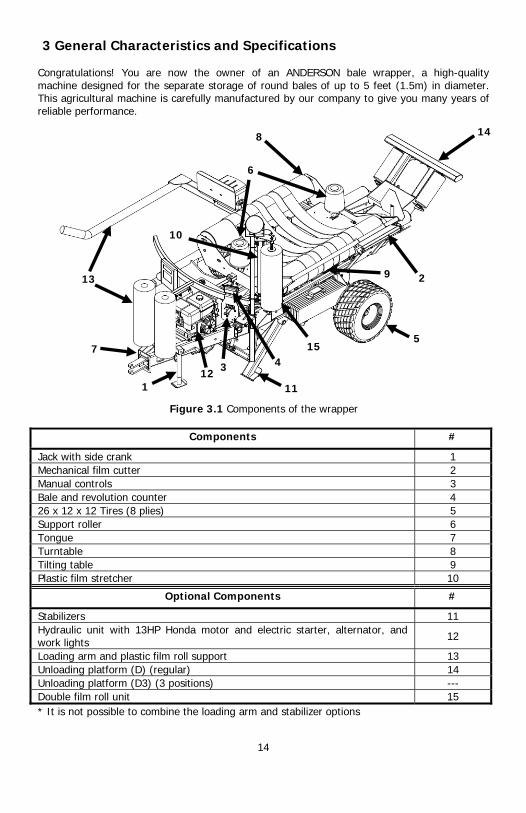
3 General Characteristics and Specifications Congratulations! You are now the owner of an ANDERSON bale wrapper, a high-quality machine designed for the separate storage of round bales of up to 5 feet (1.5m) in diameter. This agricultural machine is carefully manufactured by our company to give you many years of reliable performance.
Figure 3.1 Components of the wrapper
Components #
Jack with side crank 1 Mechanical film cutter 2 Manual controls 3 Bale and revolution counter 4 26 x 12 x 12 Tires (8 plies) 5 Support roller 6 Tongue 7 Turntable 8 Tilting table 9 Plastic film stretcher 10
Optional Components #
Stabilizers 11 Hydraulic unit with 13HP Honda motor and electric starter, alternator, and work lights 12
Loading arm and plastic film roll support 13 Unloading platform (D) (regular) 14 Unloading platform (D3) (3 positions) --- Double film roll unit 15 * It is not possible to combine the loading arm and stabilizer options
1
2
3 4
5
11 12
13
14
10
15 7
8
9
6

15
General Specifications
Figure 3.2 Exterior dimensions for the base model
Figure 3.3 Exterior dimensions for model with optional
Dimensions and Weight
for base model Dimensions and Weight for model with optional
Length (A) 140 po (3,55m) Length (D) 187,50 po (4,77m)
Width (B) 89 po (2,26m) Width (E) 100,75 po (2,56m)
Height (C) 99 po (2,51m) Height (F) 118,50 po (3,01m)
Total weight* 1896 lbs (860 kg) Weight of stabilizers 250 lbs (113 kg)
* Without hydraulic unit or optional components.
Weight of hydraulic unit 386 lbs (175 kg)
Weight of loading arm Arm: 465 lbs (210 kg) Weight:550 lbs (249 kg)
Poids support de rouleaux plastiques 20 lbs (9 kg) Weight of unloading platform D 420 lbs (190 kg) Weight of unloading platform D3 550 lbs (250 kg)
Weight of double film roll unit 55 lbs (25 kg)

16
4 Adjustment Procedures
Verifications Before Each Use
Check the hydraulic oil level in the tank of your unit if your bale wrapper is equipped with this option. Check the oil level in the Honda engine, if applicable, as well as the need for fuel. Open the fuel valve and check the engine air filter. If necessary, lubricate the machine well after each day of use. Every day, check the cleanliness of the plastic film stretcher rollers. Clean them as necessary with penetrating oil, rubbing alcohol, or paint thinner. At start-up, your bale wrapper must be placed in the most horizontal position possible. Detach the turntable’s L-shaped latch (Figure 2.1). If you have the stabilizer option, start the machine and pull the 2 levers of the control to put them in place (Figure 5.2). If the film roll is in place, check if the edge of the plastic is properly held by the clamp of the film cutter. If not, you can attach the plastic directly onto the bale ties.
Installing the Plastic Film Roll
When the film roll is empty, remove the spool by pushing it upward to compress the retaining spring of the upper support (Figure 4.1). Install the new roll in the same manner.
Figure 4.1 Installing the film roll
Follow the diagram (Figure 4.2) to unroll the start of the film between the rubber roller and an aluminium roller, then around the other aluminium roller. The edge of the plastic must be attached onto the ties or the net of the first bale.

17
Figure 4.2 Direction of film unwinding
WARNING !
Avoid leaving the plastic film rolls in the sun for a long period of time before using them. Prolonged sun exposure can cause the film to break or deteriorate during wrapping.
Testing the Plastic Film Stretcher
To check the effectiveness of your system, draw a 10-inch (25 cm) horizontal line on your plastic film roll with a felt-tip pen. Turn the table about one revolution and stop. Once the line has passed the aluminum rollers, measure it on the bale. If it has stretched up to a length of approximately 16.5 inches (41 cm), this means that your film stretcher is working properly. If the film does not stretch properly, check the gears of the film stretcher, and if the plastic film roll and the free roller turn freely, clean the aluminum rollers.
Adjusting the Two Support Rollers
These two conically shaped support rollers are made of rigid plastic and are placed on each end of the table between the feed rollers to hold your bale in place. In the factory, they are placed 48 inches (1.2 m) apart to hold bales of 48 inches (1.2 m) in width. Move them together or apart as necessary according to the average width of your bales by removing the pins beneath the table and changing their position. The support rollers can hold bales up to 60 inches (1.5 m) in width (Figure 4.3).
Figure 4.3 Adjusting the support rollers

18
5 Operating Procedures
5.1 Moving the Bale Wrapper
Short and Medium Distances
Your machine can be moved short and medium distances behind a tractor. Fasten the turntable latch (Figure 2.1). Attach the machine and attach a security chain to the ring provided for this purpose on the draw bar. On public roads, follow the traffic regulations of your region for agricultural machines, including those concerning the use of agricultural machines by minors.
Safety Measures
WARNING !
Regardless of method, during transportation, do not stand on and do not let anyone else stand on the machine.
WARNING !
Close the fuel valve if it is necessary, because the gasoline could leak into the engine base.
5.2 Using the IG-C3 Bale Counter
Characteristics
The IG-C3 bale counter is powered by a rechargeable battery. Use the provided AC/DC charger as needed. The module consists of a 2-line screen with 4 buttons beneath it. Start up the counter by touching the ON/OFF button on the left. This opens the first Anderson window. Five seconds later, the screen will look as follows: - In the upper left corner of this window, rev: 00 will count each wrapping as you operate
the bale wrapper. - On the second line of the window, Bales (D): 000 shows the total bales wrapped in the
day.- In the upper right corner, MAX: 18 shows the maximum number of revolutions
programmed for each bale. When your number of revolutions approaches this number, the screen will begin to blink. You will hear three warning beeps, but the machine will not stop automatically. Bales/total will increase by 1, and after 15 seconds, the number of revolutions will return to 0.
Figure 5.1 Bale counter screen

19
Operation Menu of the IG-C3 Bale Counter
- If you press the ER. COUNT. DAY. button, the screen will ask you to confirm NO -. or YES + whether you really want to erase the daily counter.
- Similarly, the .ER. COUNT. REV. button allows you to reset the revolution counter to zero during a test or during a missed cycle. You must confirm the operation.
- The ON / OFF. button on the right allows you to turn on or off the illumination of the screen during operation. The internal battery consumes 10 times less energy when the screen is turned off. The illumination of the screen automatically turns off after 20 seconds if the counter is not being used.
- To shut down the module and close the operation MENU, press the .ON/OFF button on the left. The data will be saved. When not being used, the bale counter will go into energy saver mode after 5 minutes.
Advanced Menu of the IG-C3 Bale Counter
To reach this menu, hold down the .ADJUST.SELECT. button for 3 seconds.
- Program 1: The 1st program allows you to: Enter the number of revolutions, MAX: 00 per bale by pushing the .- / +. buttons. The minimum number is 2 and the maximum is 80. Holding down one of the .- / +. buttons for 3 seconds will cause the number to change faster. We recommend 18 revolutions with 30-inch plastic rolls so as to obtain 4 layers on all surfaces of the bale. Certain users will want more layers or fewer layers.
- Program 2: Pushing the ADJUST. SELECT button again will take you to program 2, which allows you to modify # bales Day: 000 (in the same manner as for program 1). If you press the .- / + buttons simultaneously, the number will be reset to zero.
- Program 3: Pushing the ADJUST.SELECT button a third time will take you to program 3, which allows you to: modify # bales Year: 0000 .
- Program 4: Choose your language with the .- / + buttons: French or English.
You have finished programming the bale counter and the ADJUST.SELECT menu will bring you back to the operation menu.
5.3 Start and End Wrapping
Start-Up
WARNING !
If you do not use the optional hydraulic unit, adjust your tractor at a flow rate of 8 GPM at 2000 PSI. Make sure your bale counter has been properly programmed.
20
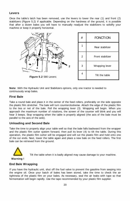
Levers
Once the table’s latch has been removed, use the levers to lower the rear (1) and front (2) stabilizers (Figure 5.2) if applicable. Depending on the hardness of the ground, it is possible that after a dozen bales you will have to manually readjust the stabilizers to solidify your machine or keep it properly horizontal.
Figure 5.2 580 Levers
# FONCTION
1 Rear stabilizer
2 Front stabilizer
3 Wrapping lever
4 Tilt the table
Note: With the Hydraulic Unit and Stabilizers options, only one tractor is needed to continuously wrap bales.
First Bale
Take a round bale and place it in the center of the feed rollers, preferably on the side opposite the plastic film stretcher. The bale will turn counterclockwise. Attach the edge of the plastic film to the ties or net of the bale. Pull the wrapping lever (3). Wrapping will begin. When you approach the maximum number of rotations, the screen of the counter will blink and you will hear 3 beeps. Stop wrapping when the table is properly aligned (the axis of the bale must be parallel to the axis of the axle).
Unloading and Second Bale
Take the time to properly align your table well so that the bale falls backward from the wrapper and the plastic film cutter system forward, then pull its lever (4) to tilt the table. During this operation, the plastic film cutter will be engaged and will cut the plastic film and hold onto one of the cut ends. Next, lower the table again and place a new bale on the feed rollers. The first bale can be retrieved from the ground.
Warning !
Tilt the table when it is badly aligned may cause damage to your machine.
End Bale Wrapping
If you have the hydraulic unit, shut off the fuel valve to prevent the gasoline from seeping into the engine oil. Once your batch of bales has been stored, take the time to check the air tightness of the plastic film on your bales. As necessary, seal the air leaks with tape so that fermentation will begin rapidly. Use the tape recommended by your plastic film supplier.
1
2 4
3
21
5.4 Bale Wrapping: Adjusting the Sensors
Adjusting the Rotation Counter Sensor
Place the 2 parts of the sensor at position 1 so that they face each other, turning the table by pulling the control valve lever, and adjust the distance between them to 1/8 inch (2.5 mm)(Figure 5.3)
Figure 5.3 Rotation counter sensor
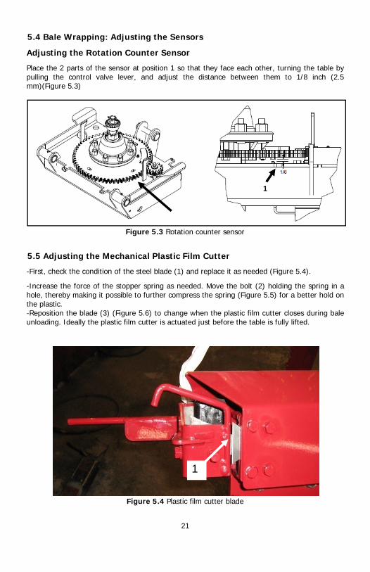
5.5 Adjusting the Mechanical Plastic Film Cutter
-First, check the condition of the steel blade (1) and replace it as needed (Figure 5.4).
-Increase the force of the stopper spring as needed. Move the bolt (2) holding the spring in a hole, thereby making it possible to further compress the spring (Figure 5.5) for a better hold on the plastic. -Reposition the blade (3) (Figure 5.6) to change when the plastic film cutter closes during bale unloading. Ideally the plastic film cutter is actuated just before the table is fully lifted.
Figure 5.4 Plastic film cutter blade
1
1

Figure 5.
Figure 5.6 Adj
2
22
.5 Stopper spring and
justing the plastic film
3
2
d adjustment bolt
m cutter blade (at rest
t)

6 Mainte
Maintenan
Warning !
Grease Gu
Your ANDERSthe sticker (F
Note: The us
Frequency
Every 200
Every 500
Every 100
* Optional eq
f
enance Procedu
nce
Before performing you are following trepair section: stopreceiver, release h
un Lubrication
SON bale wrapper muFigure 6.1).
Fig
se of synthetic grease
y Greas
0 bales
Pivot CentrPivotsAxles Axles Pivot Axles Pivot
0 bales Front
00 bales Bearintotal o
quipment
Pivot of plastic film roll support
(1)
23
ures
any maintenance opethe security precautiop the engine (of the tydraulic pressure, etc
ust be lubricated with
gure 6.1 Grease gun
e is highly recommend
Greasing Freque
sing (number of greas
of plastic film roll supral axle of turntable (1s of tilting table (2) of the tilting cylinderof the unloading platof the unloading armof the unloading armof the unloading plat
and rear stabilizers (
ngs of the two feed roof 4)
erations on your macons laid out in the safetractor or the unit), tuc.
h a grease gun in the
lubrication
ded
ency
se cups)
pport (1) 1 on the top)
r (2) tform cylinder (2)*
m (2)* m cylinder (2)* tform (4)*
(4)*
ollers of the belts (1 o
chine, ensure that e maintenance and urn off the
e places indicated by
on each end,

24
Central axle of turntable (1 on
the top)
Pivots of tilting table (2)*
Axles of the tilting cylinder
(2)

25
Axles of the unloading
platform cylinder (2)*
Pivot of the unloading arm
(2)*
Axles of the unloading arm cylinder (2)*

Bt
Pivot of the unloading
platform (4)*
Front
and rear stabilizers (2 grease cups each) and
cylinder axles (2each)*
Bearings of the two feed rollers of the belts (1 on each end,
total of 4)
26

27
Other Lubrication Points
The power transmission chains and other moving parts of the machine must be oiled or greased regularly or every 50 hours. This also applies to the 2 toothed wheels of the plastic film stretcher.
Figure 6.2 Lubricating the plastic film stretcher
Figure 6.3 Lubricating the chain (through the hole in the guard)
The film cutter must be lubricated daily (approximately 100 balls) where indicated in the following figures:
IMPORTANT !
Use a antifriction lubricant to lubricate the film cutter system. Do not use grease because it causes the accumulation of dust that affect the lubricating.

28
Figure 6.4 Lubricating the plastic film cutter 1
Figure 6.5 Lubricating the plastic film cutter 2
The film cutter must be lubricated daily (approximately 100 balls) where indicated in the following figures:
IMPORTANT !
Use a antifriction lubricant to lubricate the film cutter system. Do not use grease.
Cleaning and Other Maintenance
Pay particular attention to the cleanliness of the plastic film cutter system. An accumulation of debris (hay, dust, string, etc.) can reduce its functionality. Regularly check the cutting condition of the blade. Always keep the rollers and the gears of the plastic film stretcher free of all residues to prevent these parts from jamming, breaking, or tearing the plastic film. As necessary, wash the aluminum rollers with rubbing alcohol, penetrating oil, or paint thinner.

29
Also remove the hay that can get stuck in the axles and gears of the machine to not place needless strain on the hydraulic motor. For the maintenance of the hydraulic unit, we recommend that you follow the Honda instruction manual for the maintenance of your engine. Check the oil level of the HONDA engine on each day of operation. The engine air filter must be checked each time you begin wrapping and cleaned as needed. As for changing the hydraulic oil, filter, and strainer, we recommend that you perform this maintenance every 5000 wrapped bales. It is a good idea to free the area around the gasoline engine of all flammable material.
Storage
To unhitch the machine, follow these steps:
Warning !
During unhitching operations, the operator is the only person authorized to be near the machine. Before lowering the tractor to remove the hydraulic connections, and the electric cables, the operator must ensure that the machine is fully on the ground and stable. S/he must also engage the hand brake, turn off the tractor, and remove the key from the ignition switch.
- Secure the machine in a stable location. - Use chocks to prevent the machine from moving while being unhitched from the tractor. - Disconnect the hydraulic connections from the tractor. - Disconnect the power cables. - Remove the fixing pin and the security chain to rotate the jack. - Replace the fixing pin and the security chain. - Lift the pole with the jack. - Remove the fixing pin and the security chain.
Warning !
Ensure that you have released the hydraulic pressure from the tractor’s system to make disconnection and future reconnection easier.
- Remove the bale counter and store in a dry place.
It is preferable to keep the machine in a dry, covered place so that it will be in good condition when it is used again.

30
7 Troubleshooting: Problems and Solutions Before calling a technician, examine your machine and consult the table below to find a solution. If you are still not able to solve the problem yourself, ask for help from the customer service department of your agricultural dealer.
Troubleshooting Table
Problems Possible Causes Solutions 1. The IG-C3 counter does not turn on. Lack of power. Install the provided AC/DC charger
or the charge wire on the module. 2. The IG-C3 turns on but does not count revolutions.
Defective sensor or problem with wiring or connections.
Check the wiring and connections, replace the sensor if necessary.
3. The engine of the hydraulic unit does not start.
The fuel valve is closed. Open the fuel valve and start again.
The gas tank is empty. Put fuel in the tank and start again.
The low engine oil sensor is activated.
Add oil to the engine and start again.
The spark plug is clogged or defective Clean the spark plug or change it.
The engine is flooded because the fuel valve was not closed the previous day or during transportation.
Remove the spark plug, dry it out, dry out the cylinder by activating the starter crank. Put back the spark plug and start again.
The fuse in the HONDA switch key box is burned out Replace the fuse (Figure 7.1)
4. The turntable does not turn or turns slowly.
The level of hydraulic oil or the flow rate of the hydraulic unit or the tractor is too low
Check for oil leaks and breaks. Retighten or repair as necessary. Add hydraulic oil to the tank. Check the tractor’s flow rate (8 GPM).
The HONDA motor turns too slowly. The motor must be adjusted to 3600 revolutions/min.
5. The plastic film wrapping is unsatisfactory.
The plastic film breaks, develops holes, or tears during wrapping.
Check if the roll installed was damaged to begin with and replace it if necessary. Check if hay or something else is inhibiting or blocking the plastic film stretcher. Remove the object and clean the film stretcher. Check if all the rollers are turning freely. The film is too soft because is has been in the sun for too long before being used. Install a cooler roll.
The plastic film is not tight enough on the bale.
Check if the plastic film roll is properly installed. Check if the parts of the plastic film stretcher are in good condition and turn freely. Repair as needed.
6. The plastic film cutter does not work well.
The plastic film cutter clamp does not hold onto the end of the plastic film.
The rubber stopper moves back too far on its adjustment bolt. Adjust the bolt. The stopper spring needs to be more tense (Figure 5.5).

31
Figure 7.1 Starter fuse
Fuse

32
8 Optional Equipment
Hydraulic Unit
The 580 bale wrapper can function with your tractor’s hydraulic system or with an optional independent hydraulic unit which includes:
- A 13 horsepower Honda gasoline engine;
- A pump adapter and a hydraulic pump;
- A hydraulic oil tank with oil filter and strainer.
IMPORTANT !
We recommend that you follow the Honda instruction manual for the proper maintenance of your engine. The engine air filter must be checked at the start of each wrapping session and cleaned as needed
We recommend that you change the hydraulic oil, the filter, and the strainer every 5000 wrapped bales.
Electric starter with 18 amp. alternator and work light
These 2 options complement the Honda engine of the hydraulic unit. The work light (1) is installed on top of the plastic film stretcher (Figure 8.1).
Figure 8.1 Hydraulic unit and work light
1

33
Stabilizers
Activated by hydraulic cylinders and controlled by manual controls at the front of the machine, these two pieces of equipment improve the stability of the bale wrapper. They are equipped with security valves (lock valves) to prevent inadvertent movement of stabilizers or the feet from collapsing, whether the machine is turned on or not. The stabilizer option and the hydraulic unit option make it possible to completely detach the bale wrapper and to function independently, one tractor is required to handle bales.
Figure 8.2 Stabilizers
Modifying Gears to Reduce Stretch Ratio
It is possible to modify the standard stretch ratio (65%) by changing the gears of the plastic film stretcher and thereby obtain a ratio of approximately 55%. Contact your dealer to obtain this accessory.
Bale Loading Arm and Plastic Film Roll Support
As an option, a loading arm can be installed on the bale wrapper only at Anderson manufacture. This arm makes it possible to load bales directly onto the bale wrapper without using a frontal loader.
1. The loading arm option is always sent with extension cables to control the wrapper from the tractor seat and a rack to carry two extra rolls of plastic.
2. For loading the bale, the turntable must be parallel to the loading arm.
3. The loading arm is equipped with a safety device to prevent collisions with the turntable and error operations. The loading arm must be dropped halfway between the turntable and the ground so that the table can rotate and wrap.
4. Ajustment of the loading arm : Fork outer arm adjusts to different bale diameter. An adjustable backstop allows you to charge balls of 4 or 5 feet (1.2 m or 1.5m) wide and filed on the center of the turntable.
5. Transport

34
WARNING !
To transport the wrapper equipped with a loading arm, install the safety pin (1) that keeps the loading arm upright.
Figure 8.3 Bale loading arm
Bale Unloading Platform (D)
Figure 8.4 Bale unloading platform D
This unloading ramp makes it possible to gently discharge wrapped bales behind the bale wrapper. This system is composed of a rigid platform, a hydraulic cylinder, and a maintenance-free nitrogen cylinder.
1

35
Unloading Platform (D3)
Figure 8.5 Bale unloading platform D3
This optional equipment makes it possible to bring the bales to a vertical position and set them down on the flat side. Additionally, this unloading platform makes it possible to turn bales on one side or the other according to the preference of the user. To make this change, the operator need only place the barrier (6) on top of the platform, the foot (4), the support roller (1), and the retaining bar (5) on the other side of the unloading platform. The same attachment points are situated on each side of the platform to facilitate the change.
WARNING !
For transport, it is necessary to manually retract the retaining bar (2) (Figure 8.5).
With the D3 option, it is possible to gently discharge bales on the cylindrical side (without rotation). The operator need only raise the foot, remove the support roller (1), and ensure that the 2 platform barriers are installed to limit movement. Installation of the three position unloading platform (D3) Here are the steps to install the unloading platform D3 from the unloading platform D :
5
4
2
1
3

36
Installation of the foot
Sand the shaft.
Slide the foot on the shaft and lock in place with the linchpin.
(1).
Attaching the retaining arm on the support
Install the support of the arm.
1

37
Place the support on the dumping unit and bolt into
place. Holes on the dumper are predrilled from the factory.
Installation of the retaining arm
Insert the fixed part of the arm into
the support.
You can now attach the ‘’L’’ shaped bar to the straight bar.
(4 bolts)

38
Installation of the cone shaped roller
Remove the deflector at the end of the dumper to reveal the placement holes for the
cone shaped roller.
Place the cone shaped roller on the same side as the foot as you will be bumping the bale to the opposite side.
This procedure is for if you are dropping the bale to the left side. The same procedure is used when dumping to the right side but the foot and cone roller will be placed on the other side of the machine. Also the ‘’L ‘’ shaped retaining arm must be inserted opposite to the procedure. Charging the accumulator When the unloading platform does not go back to its position, you must correct the pressure in the accumulator to a pressure ranging from 1000 to 1200 lbs. A too low pressure will not lift the unloading platform to its position and a too high pressure will not allow the bale to dump from the unloading platform.
1. Remove the handle (1) 2. Turn the lock washer (2) to enable the handle to turn and open the ball valve (4). 3. Replace the handle (1). 4. Connect a hydraulic pump at the male quick connect (3). 5. Open the ball vale (4). The unloading platform will go down. 6. Put hydraulic oil to achieve a pressure of 1000 lbs. Press on the unloading platform
for to verify if he goes back to its position and adjust the pressure as required.
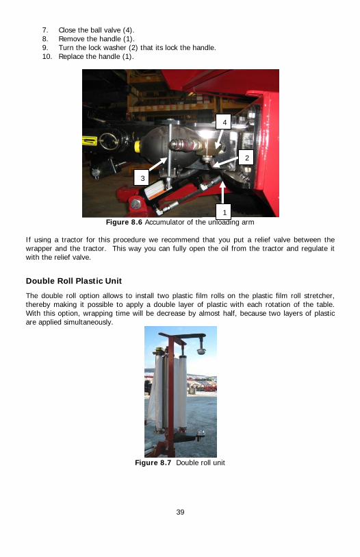
7. Clo8. Re9. Tu10. Re
If using a trawrapper and with the relie
Double Ro
The double rthereby makWith this optare applied s
ose the ball valve (4).move the handle (1).rn the lock washer (2place the handle (1).
Figure 8
actor for this procedthe tractor. This wa
ef valve.
oll Plastic Unit
roll option allows to ing it possible to apption, wrapping time wimultaneously.
39
2) that its lock the han
8.6 Accumulator of th
ure we recommend ay you can fully open
install two plastic filmply a double layer ofwill be decrease by a
Figure 8.7 Double r
3
ndle.
e unloading arm
that you put a reliefn the oil from the tra
m rolls on the plastif plastic with each ro
almost half, because t
roll unit
1
2
4
f valve between the actor and regulate it
c film roll stretcher, otation of the table. two layers of plastic

40
9 Start-Up Procedures When you receive your new ANDERSON equipment: Stationary mode:
1. Attach the bale wrapper to the tractor or stabilize the machine with the stabilizers and
start the engine HONDA. 2. Remove the table lock on the bale wrapper (Figure 2.1). 3. Install a plastic film roll (Figure 4.1). 4. Enable the tractor hydraulic system or start the Honda engine. 5. Place a bale on the table, centered between the support rollers. 6. Attach the edge of the plastic film to the ties of the bale. 7. Pull the lever to begin wrapping (Figure 5.2). 8. Adjust the revolution of the engine to the wrapping speed desired.
Field mode: 1. Remove the table barrier on the bale wrapper (Figure 2.1). 2. Install a plastic film roll (Figure 4.1). 3. Enable the tractor hydraulic system or start the HONDA engine. 4. Place a bale on the table with the loading arm. 5. Only for the first bale, attach the end of the plastic wrap on the rope or bale net. 6. Pull the lever to begin wrapping (Figure 5.2). 7. Adjust the revolution of the engine to the wrapping speed desired.

Parts manual
ROUND BALE WRAPPER RB580
ALWAYS KEEP THIS MANUAL WITH THE WRAPPER


Content
1 – Main Frame P. 2
2 – Plastic Roller Frame, Coupling Hand and Tongue P. 3
3 – Axle P. 4
4 – Stretcher Support Arm P. 5
5 – Stretcher Support P. 6
6 – Stretcher P. 7
7 – Dumping Table P. 8-10
8 – Shield P. 11
9 – Rotary Table and Cut and Hold P. 12-16
10 – Power Unit (option) P. 17
11 – Loading Arm P. 18-21
12 – Drop Off (option) P. 22-24
13 – Stabilizer (option) P. 25
14 – Hydraulic Diagram P. 26-32
For any parts order, please use the parts manual to find the item(s) you need and contact your dealer to order it or contact us directly at :
ANDERSON GROUP 5125 de la Plaisance Chesterville (Québec) CANADA G0P 1J0
Fax : (819) 382-2643 Email : [email protected]
Visit our website www.grpanderson.com
1

Anderson Group, 5125 de la Plaisance Chesterville (Québec) G0P 1J0Email : [email protected]
PARTS LIST
ITEM QTY PART DESCRIPTION1 1 222000-1 FRAME2 7 500444 CARRIAGE BOLT3 5 223001 HOSE ATTACHMENT4 1 466000 CUSHION VALVE5 10 501030 NYLON NUT6 4 500014 BOLT7 1 223003 PIVOT AXLE8 4 500443 CARRIAGE BOLT9 4 501022 FLANGE NUT10 2 465063 VALVE11 1 501031 NYLON NUT12 1 500334 BOLT13 1 222001 VALVE SUPPORT14 9 501032 NYLON NUT15 2 500084 BOLT16 6 500016 BOLT17 1 500044 BOLT
PARTS LIST
ITEM QTY PART DESCRIPTION18 1 501037 NYLON NUT19 5 451172 HYDRAULIC FITTING20 2 451355 HYDRAULIC FITTING21 2 466989 VALVE22 6 451260 HYDRAULIC FITTING23 2 451171 HYDRAULIC FITTING24 1 450972 HYDRAULIC FITTING25 2 322299 GREASE FITTING26 1 222042 TRIGGER ARM TIP27 1 222041 TRIGGER ARM28 1 500173 BOLT29 2 500570 SHOULDER SCREW30 1 502048 LOCK WASHER31 1 222044 TRIGGER ARM ADJUSTMENT32 1 222043 DUMPING TABLE AXIS33 1 502006 FLAT WASHER34 2 451261 HYDRAULIC FITTING
1 - MAIN FRAME
22
23
21
22
236
22
22
2222
2119
4
19
24196
20
17
11
34
1634
10
2
3
14
8
7
925
15
18
14
13
526
30
28
27
2929
33 31
328
1
12
20
16
5
1019
19
2

DETAIL A
Anderson Group, 5125 de la Plaisance Chesterville (Québec) G0P 1J0Email : [email protected]
A
PARTS LISTDESCRIPTIONPARTQTYITEM
PLASTIC ROLLER SUPPORT224082-121FLANGE NUT50102222CARRIAGE BOLT50044223
PARTS LISTDESCRIPTIONPARTQTYITEM
TONGUE22200211NYLON NUT50103222JACK32245013HOSE ATTACHMENT22300124CARRIAGE BOLT50044425WELD NUT507011223
PARTS LISTDESCRIPTIONPARTQTYITEM
COUPLING HAND22307612BOLT50017743FLANGE NUT50102446
2 - PLASTIC ROLLER SUPPORT, COUPLING HAND AND TONGUE
1
23
2
3
1
3
4
5
2
COUPLING HAND
ROLLER SUPPORT
TONGUE
3

Anderson Group, 5125 de la Plaisance Chesterville (Québec) G0P 1J0Email : [email protected]
PARTS LISTDESCRIPTIONPARTQTYITEM
DOMPING TABLE LOCK22308411BOLT50008812FLANGE NUT50102253CARRIAGE BOLT50044344HUB48140025.1COTTER PIN32000225.2CASTLE NUT50107625.3FLANGE NUT501024136BOLT50017597CARRIAGE BOLT50050148COMPLETE RIGHT AXLE223080-119COMPLETE LEFT AXLE223081-1110TIRE AND RIM481604211
PARTS LISTDESCRIPTIONPARTQTYITEM
HUB48140011BEARING30303512BEARING30303613ROLLING BEARING CAGE30303714BEARING30303415SEAL30307716DUST CAP48100017WHEEL BOLT50701058
3 - AXLES
5.1
5.2
5.3
10 67
3
46
8
1
3
2
8
6911
7
23
8
14
5
6
4

Anderson Group, 5125 de la Plaisance Chesterville (Québec) G0P 1J0Email : [email protected]
PARTS LISTDESCRIPTIONPARTQTYITEM
ARM22306711CARRIAGE BOLT50050262REINFORCEMENT22306813CARRIAGE BOLT50044224LOCK32002116NYLON NUT50103237FLANGE NUT50102468BOLT500099123
4 - STRETCHER SUPPORT ARM
1
62
8
4
3
47
5

Anderson Group, 5125 de la Plaisance Chesterville (Québec) G0P 1J0Email : [email protected]
PARTS LISTITEM QTY PART DESCRIPTION
1 1 224076 STRETCHER'S POST2 2 303012 BEARING3 1 224077 SHAFT4 1 322299 GREASE FITTING5 1 320039 HITCH PIN6 1 224078 SPRING HOLDER7 1 224079 ROD8 1 224080 SPRING HOLDER9 1 500084 BOLT
10 1 224081 TEFLON BREAK11 1 502001 FLAT WASHER12 1 501036 NYLON NUT13 2 224082 ROLLER SUPPORT14 1 319880 WORK LIGHT
PARTS LISTITEM QTY PART DESCRIPTION
15 2 306018 AXLE16 1 224084 RUBBER ROLLER17 1 304007 SPRING18 1 304008 SPRING19 2 502004 FLAT WASHER20 2 500104 BOLT21 3 501032 NYLON NUT22 1 304023 SPRING23 1 304009 SPRING24 1 320002 PIN25 1 507036 ALLEN SET SCREW26 1 500289 BOLT27 1 500004 BOLT28 1 501030 NYLON NUT
5 - STRETCHER SUPPORT
7
28
27
13
2
26
2
24
1125
1
20
17
6
19
21
20
19
18
8
21
21
9
14
22
10
12
3
13
23
4
5
15
16
15
6

Anderson Group, 5125 de la Plaisance Chesterville (Québec) G0P 1J0Email : [email protected]
PARTS LISTDESCRIPTIONPARTQTYITEM
BEARING CUP22406721GEAR27910212GEAR27910013SPACER22406824BOLT50001725ALUMINUM ROLLER27900426LOWER BRACKET22406517UPPER BRACKET22406618ROD22407019BOLT500004510BEARING CUP224067211SHIELD224071112NYLON NUT501030813BOLT500006414PLASTIC SHIELD224075115KEY320022216FLANGE NUT501020217GREASE FITTING322299118BEARING303018419FLANGE NUT501022220GEAR279103121GEAR279104122
6- STRETCHER
12
2
16
17
10
20
14
713
11
19
9
15
20
19
1
13
14
138
3
4
18
5
22
21
6
7

Anderson Group, 5125 de la Plaisance Chesterville (Québec) G0P 1J0Email : [email protected]
7- DUMPING TABLE
1314
10
18
15
8
637
4
9 1
11
4
20
12
16
17
2
5
19
23
24
22
21
1
25
8

Anderson Group, 5125 de la Plaisance Chesterville (Québec) G0P 1J0Email : [email protected]
PARTS LIST
DESCRIPTIONPARTQTYITEMHYDRAULIC FITTING45071221DOMP. TABLE CYLINDER46702912GREASE FITTING32229523
PARTS LIST
DESCRIPTIONPARTQTYITEMPLASTIC NUT31500741GREASE FITTING32229912NYLON NUT50103423BOLT50000424GEAR30051315HYDRAULIC FITTING45117326HYDRAULIC MOTOR46914717TABLE22200518WIRED SENSOR31500419SPRING PIN320074 110CAP223018111NYLON NUT501030112HITCH PIN CLIP320010113FRONT GUARD222045114REAR GUARD222046115WASHER210629116LOCK WASHER502046117BOLT500001118BOLT500179219NYLON NUT501037120BOLT500006121SHUTTER222053122LOCK WASHER502045223BOLT500084224BOLT500333125
7 - DUMPING TABLE
21
1
9

Anderson Group, 5125 de la Plaisance Chesterville (Québec) G0P 1J0Email : [email protected]
PARTS LIST
DESCRIPTIONPARTQTYITEMKEY22403511COTTER PIN32001712BOLT50021183CASTLE NUT50107614CONIC GEAR30050915CASTLE NUT501120 16GEAR223022-217SENSOR31500418PLASTIC NUT31500729HUB481404110COTTER PIN320002111BEARING CUP303493112WHEEL NUT501902113BEARING CUP303492114BEARING303491115DUST CAP303490116BEARING303494117
7 - DUMPING TABLE
11
4
1
2
5
6
17
12
13
10
14
15
16
7
8
9
3
10

Anderson Group, 5125 de la Plaisance Chesterville (Québec) G0P 1J0Email : [email protected]
PARTS LIST
DESCRIPTIONPARTQTYITEM
SELF-DRILLING SCREW50700631
OPERATOR'S MANUAL BOX325109-112
CYLINDER BOX32512013
COUNPTER31500614
FLAT WASHER50201445
NYLON NUT50103126
BOLT50005927
VALVE46601518
HYDRAULIC FITTING45126529
HYDRAULIC FITTING451227410
BOLT500084411
SHIELD222003112
CARRIAGE BOLT500442213
FLANGE NUT501022214
LOCK WASHER502045415
8- SHIELD
11
2
1
3
5
6
4
8
9
9
10
5
7
12
10
10
10
15
13
14
11

Anderson Group, 5125 de la Plaisance Chesterville (Québec) G0P 1J0Email : [email protected]
9 - ROTARY TABLE
39
12
11
6
9
7
9
5
23
35
40
36
47
10
22
2
21
4
38
19
3
4
20
13
14
29
31
33
32
15
37
34
17
8
8
1
28
16
2618
4125
3044
45
43
46
25
24
17
42
4951
54
50
53
4852
27
15
12

Anderson Group, 5125 de la Plaisance Chesterville (Québec) G0P 1J0Email : [email protected]
PARTS LIST
DESCRIPTIONPARTQTYITEMTAB22318211ROTATING ROLL'S SHAFT22204012GEAR300511M113ALLEN SET SCREW507005144ROLLER SUPPORT STAND SHAFT22302625PLASTIC HOLE PLUG32510726PLASTIC ROLLER32511227BEARING30304548SNAP RING32000649PIN320039210DRIVING ROLLER223039111DRIVED ROLLER223040312ROD230041213BOLT500084214FLANGE NUT501022515SPROCKET301101116NYLON NUT501035817ADJUSTMENT WASHER485548118BEARING303989119KEY222015220KEY224014121SPROCKET223035122CHAIN GARD ON PIV.TABLE223042123BOLT500060224NYLON NUT501031425BOLT500249126LOCK SUPPORT222038227BUTTON HEAD SCREW507065628BOLT500246429STOPPER485576130LOCK222039131CARRIAGE BOLT500444232CARRIAGE BOLT500442133GREASE FITTING322299434ALLEN SET SCREW507003235SPROCKET301050136BEARING303024437GEAR300511138BELT322603439FLANGE BEARING303050240BEARING303000141BOLT500245442FLANGE NUT501025143BOLT500050244FLAT WASHER502014245GREASE FITTING322295146CARRIAGE BOLT500360347MOUNTING SUPPORT210758148BOLT500004249NYLON NUT501030250SECURITY TRIANGLE325145151NYLON NUT501032252CARRIAGE BOLT500440253TRIANGLE SUPPORT222055154
9 - ROTARY TABLE
13

Anderson Group, 5125 de la Plaisance Chesterville (Québec) G0P 1J0Email : [email protected]
PARTS LIST
DESCRIPTIONPARTQTYITEM
CUT AND HOLD UPPER SECTION22200611
CUT AND HOLD BOTTOM SECTION22200712
HOLDING ROLLER22304923
ROTARY TABLE22200814
9 - ROTARY TABLE AND CUT AND HOLD
2
3
4
1
14

Anderson Group, 5125 de la Plaisance Chesterville (Québec) G0P 1J0Email : [email protected]
PARTS LIST
DESCRIPTIONPARTQTYITEM
ATTECHEMENT PLATE 11
HAMMER SHAFT22202312
CARRIAGE BOLT50050083
FLANGE NUT50102484
HOOK22202525
HAMMER AND BUFFER SUPPORT22203716
BUFFER SUPPORT22202617
HAMMER SUPPORT22202718
BLADE HOLDING PLATE22202819
BLADE MOUNTING PLATE222029110
COVER222030111
BOLT500084112
HAMMER'S PLATE222031113
SPRING304010114
SPRING'S PLATE222033215
RUBBER BUFFER222034116
CARRIAGE BOLT5004421417
FLANGE NUT5010221618
BOLT500042319
BOLT500044220
LOCK WASHER502065221
SPRING304012122
HAMMER'S ROLL222035123
PLASTIC CUT SUPPORT238009124
BOLT500096125
LOCK WASHER502045126
BLADE325108127
SPRING PIN320050228
NYLON NUT501030329
FLANGE NUT501020130
BOLT500006131
BOLT500004232
FLANGE NUT501021133
9 - CUT AND HOLD
1
25
18
18
22
24
5
3
17
8
19
17
33
6
7
17
16
15
12
26
31
30
23
13
14
29
2
32
3
4
3
18
17
4
18
18
9
10
27
28
19
11
21
20
15

Anderson Group, 5125 de la Plaisance Chesterville (Québec) G0P 1J0Email : [email protected]
PARTS LIST
DESCRIPTIONPARTQTYITEM
RACK AND PINION23800811
SPACER22201012
SPACER22201123
RACK AND PINION HOLDING PLATE22201214
CAME22201315
CAM SHAFT22201416
GEAR30051117
ALLEN SET SCREW50700528
KEY22201529
BEARING MOUNTING PLATE222016210
BEARING303028211
ACTIVATION PLATE222017112
SPRING304030113
TRANSFER PLATE222018114
TRANSFER BRACKET222019115
SHOULDER SCREW500570216
FLANGE NUT501022717
RACK AND PINION PLATE222020118
RACK AND PINION HOOK222021219
FLANGE NUT501024620
FLANGE NUT501021221
CARRIAGE BOLT500403222
CARRIAGE BOLT500503423
CAM FINGER222022124
BEARING303021-1125
FLAT WASHER502004126
BOLT500082127
CARRIAGE BOLT500444228
CARRIAGE BOLT500442129
ALLEN SET SCREW507003430
GREASE FITTING322299431
CARRIAGE BOLT500501232
BOLT500092133
RETAINING RING320060134
8
7
13
9
9
6
30
20
31
30
11
10
23
5
17
20
16
12
24
25
26
27
28
4
3
20
2
21
16
1
19
32
18
17
33
17
17
14
29
17
22
15
9 - CUT AND HOLD
34
16

Anderson Group, 5125 de la Plaisance Chesterville (Québec) G0P 1J0Email : [email protected]
PARTS LISTDESCRIPTIONPARTQTYITEM
LOCK PIN22305811SPRING30401012GREASE FITTING32229913OUTER FORK22305914FLAT WASHER50200425BOLT50008846NYLON NUT50103247GREASE FITTING32229928CAM223087-119LOCK223055110BALE STOPPER223056111CARRIAGE BOLT500501312FLANGE NUT501024313LOADING ARM FRAME223057-1114BUSHING303051115
11 - LOADING ARM
2
15
75
6
6
8
14
3
12
13
7
10
6
11
41
8
5
79
17

Anderson Group, 5125 de la Plaisance Chesterville (Québec) G0P 1J0Email : [email protected]
PARTS LISTDESCRIPTIONPARTQTYITEM
ENGINE60500611PUMP468495-46800212HYDRAULIC FITTING45117913FLAT WASHER50200444BOLT50008825NYLON NUT50103246VOLTAGE REGULATOR60500917NYLON NUT50103048LOCK WASHER50204549BOLT500084410INSERT322020111COUPLING322050112COUPLING322042113BOLT500114214BATTERY HOLDER224110115BATTERY470113116TANK CAP470112117BOLT500006218HYDRAULIC FITTING451190119TANK224108120STRAINER470990121DRAIN PLUG470117122HYDRAULIC FITTING450725123HYDRAULIC FITTING450717124BOLT500092425FLANGE NUT501022426FLANGE NUT501020227BOLT500004228PUMP ADAPTER322008129
10 - POWER UNIT
5
22
3
2321
7
18
16
17
6
15
19
24
2
6
9
10
1311
12
4
1
OPTION
20
25
26
14
8
28
27
29
18

Anderson Group, 5125 de la Plaisance Chesterville (Québec) G0P 1J0Email : [email protected]
PARTS LISTDESCRIPTIONPARTQTYITEM
FLANGE NUT50102421CARRIAGE BOLT50050122BOLT50017323LOCK WASHER50204824COUNTERWEIGHT22308315SUPPORT22308216
PARTS LISTDESCRIPTIONPARTQTYITEM
HYDRAULIC FITTING45071211HYDRAULIC CYLINDER46715212GREASE FITTING32229923CYLINDER AXLE22309824SNAP RING320005-125WASHER22309926HYDRAULIC FITTING450712M17
11 - LOADING ARM
4
11
3
4
23
5
2
1
5335
6
4
8
6
4
6
19

Anderson Group, 5125 de la Plaisance Chesterville (Québec) G0P 1J0Email : [email protected]
PARTS LISTDESCRIPTIONPARTQTYITEM
REAR ATTACHMENT22306011FLANGE NUT50102412CARRIAGE BOLT50050124PIN22306115LOCK32001016FLANGE NUT50102477NYLON NUT50103218BOLT50009619CARRIAGE BOLT500504515
PARTS LISTDESCRIPTIONPARTQTYITEM
FRONT ATTACMENT22306311PIN22306612CARRIAGE BOLT50050263FLAT WASHER50200414LEVER22306515SPACER22306416FLANGE NUT50102467BOLT50009618NYLON NUT50103239BOLT500088210
11 - LOADING ARM
14
15
2
9
8
5
6
7
5
10
4
69
37
2
89
1
7
20

Anderson Group, 5125 de la Plaisance Chesterville (Québec) G0P 1J0Email : [email protected]
PARTS LISTDESCRIPTIONPARTQTYITEM
CABLE CONTROL46549431CONTROL CABLE ATTACHMENT22204812CONTROL PLATE22204913PLATE ATTACHMENT22205024ASSEMBLY SUPPORT21075815CARRIAGE BOLT50040326LOCK WASHER50206547NUT50100128BUTTON HEAD SCREW50706469NYLON NUT501049610BOLT501077-1611BOLT500044212FLAT WASHER502014413COMPLET CONTROL KIT 222051114
PARTS LISTDESCRIPTIONPARTQTYITEM
HYDRAULIC FITTING45122911HYDRAULIC FITTING45123012HYDRAULIC VALVE46591813HYDRAULIC FITTING45122664VALVE PIECE CABLE46549235CABLE465490 16
11 - LOADING ARM
7
13
4 12
4
65 10
7
83
11
9
2
9
1
6 5
24
4
4
4
4
4
1
3
14
21

And
erso
n Gr
oup,
512
5 de
la
Plaisa
nce
Ches
terv
ille
(Qué
bec)
G0P
1J0
E
mail :
serv
ice@
grpa
nder
son.
com
12 -
DR
OP
OFF
1016
237
7
19
3129
26
28
24
25
27
30
58
1112
911
1914
1
4
9
11
11
20
22
13
2
36
1715
15
21
18
22

PA
RTS
LIS
TD
ESC
RIP
TIO
NP
AR
TQ
TYIT
EMD
RO
P O
FF A
XLE
2230
941
1B
US
HIN
G22
4092
82
RO
LLE
R21
0523
43
HYD
RA
ULI
C F
ITTI
NG
4709
931
4S
UP
POR
T22
3008
15
RO
LLE
R L
OC
K21
0521
46
CAR
RIA
GE
BO
LT50
0455
27
NYL
ON
NU
T50
1032
28
CYL
IND
ER
PIN
4675
00
29
FLA
NG
E N
UT
5010
2417
10C
YLIN
DE
R C
LIP
PIN
4675
014
11N
YLO
N N
UT
5010
311
12H
ITC
H P
IN32
0039
413
GR
EA
SE
FIT
TIN
G32
2299
414
BO
LT50
0082
215
BO
LT50
0177
916
SE
LF-D
RIL
LIN
G S
CR
EW
5070
39-1
417
HYD
RA
ULI
C C
YLI
ND
ER
4670
981
18H
YDR
AU
LIC
FIT
TIN
G45
0711
219
DR
OP
OFF
PLA
TE22
3089
-11
20TA
BLE
2230
90-1
121
TAB
LE A
XLE
2230
91-1
222
DR
OP
OFF
ATT
AC
HM
EN
T22
3088
-11
23A
CC
UM
ULA
TOR
4701
081
24H
YDR
AU
LIC
VAL
VE
4669
99-1
125
HYD
RA
ULI
C F
ITTI
NG
4501
321
26H
YDR
AU
LIC
FIT
TIN
G45
0007
127
HYD
RA
ULI
C F
ITTI
NG
4510
941
28H
YDR
AU
LIC
FIT
TIN
G45
0262
129
HYD
RA
ULI
C F
ITTI
NG
4520
001
30D
OU
BLE
RE
LIE
F VA
LVE
4650
511
31
And
erso
n Gr
oup,
512
5 de
la
Plaisa
nce
Ches
terv
ille
(Qué
bec)
G0P
1J0
E
mail :
serv
ice@
grpa
nder
son.
com
12 -
DR
OP
OFF
23

DETAIL A
Groupe Anderson, 5125 de la Plaisance Chesterville (Québec) G0P 1J0Email : [email protected]
A
PARTS LISTDESCRIPTIONPARTQTYITEM
ARM SUPPORT22309311ARM LOCK22318512SPRING PIN32007313SPRING30403414TOP LINK22417515FLANGE NUT501024176CARRIAGE BOLT50050187LINCHPIN32000718HITCH PIN32003949TOP LINK PIN320082210GREASE FITTING322299411FIXED PART OF ARM223183112REMOVABLE PART OF ARM223184113OUTRIGGER223186-1214ROLLER SUPPORT AXLE223187115CAP325107116ROLLER SUPPORT325112117BEARING303045218RETAINING RING320006219
12 - DROP-OFF
9
105
911
810 14
12
1
6
7
6 7
13
15
19
18
17
18
19
16
2
3
4
24

Anderson Group, 5125 de la Plaisance Chesterville (Québec) G0P 1J0Email : [email protected]
PARTS LISTDESCRIPTIONPARTQTYITEM
BOLT50033451REAR STABILIZER22317022BOLT50033313HALF NYLON NUT50105774GREASE FITTING32229945FRONT STABILIZER22317126REAR STABILIZER SUPPORT22317217FLANGE NUT501024148CARRIAGE BOLT500500 149CYLINDER467026210BOLT500330111HYDRAULIC FITTING450712412GREASE FITTING322295413STABILIZER SUPPORT223173-1214ATTACHMENT223304115COTTER PIN320043116
13 - STABILIZER
4
1
8
4
1112
10
12
4
32
7 9
5
6
14
14 10
12
134
4
9
8
1
15
13
16
5
1
25

Grou
pe A
nder
son
/ And
erso
n Gr
oup,
512
5 de
la
Plaisa
nce
Ches
terv
ille
(Qué
bec)
G0P
1J0
Em
ail :
ser
vic
e@an
der
so
n-e
qu
ipm
ent.
com
54
05
-6-8
2X
53
15
-6-1
0
57
06
-61
70
0 P
SI
2X
53
15
-6-8
53
15
-6-8
RE
NIF
LA
RD
V
EN
T
54
05
-6-8
2X R
AC
CO
RD
RA
PID
E M
ÂLE
1/2
2X M
AL
E Q
UIC
K
CO
UP
LER
1/2
SO
RT
IE D
U T
RA
CT
EU
R
OU
T-T
RA
CT
OR
EN
TR
ÉE
DU
TR
AC
TE
UR
IN
-TR
AC
TO
R
MO
TE
UR
DE
TA
BL
E P
IVO
TA
NT
E
R
OT
AR
Y T
AB
LE
MO
TO
R
LIM
ITE
UR
DE
PR
ES
SIO
N
R
EL
IEF
VA
LV
E
CY
LIN
DR
E D
U D
OM
PE
UR
D
RO
P-O
FF
CY
LIN
DE
R
VA
LV
E 2
SE
CT
ION
S2
SE
CT
ION
S V
AL
VE
CY
LN
DR
E D
E T
AB
LE
BA
SC
UL
AN
TE
DU
MP
ING
TA
BL
E C
YL
IND
ER
14
- D
IAG
RA
MM
E H
YD
RA
UL
IQU
E 5
80
/ 5
80 D
580
M /
58
0 M
D H
YD
RA
UL
IC D
IAG
RA
M
09
-42
09
-41
09
-45
09
-08
09
-09
09
-32
09
-29
09
-30
4X
53
65
-6-8
55
15
-8-8
55
15
-8-8
AC
CU
MU
LAT
EU
RA
CC
UM
ULA
TO
R3
36
9-6
-6
VA
LV
E À
BIL
LE
B
ALL
VA
LV
E
30
69
-8-6
RA
CC
OR
D R
AP
IDE
MÂ
LE 1
/2 M
AL
E Q
UIC
K C
OU
PLE
R 1
/2
09
-32
-1
PA
B7
23
8-8
53
15
-6-8
VA
LV
E D
ÉV
IA.
TA
BL
E B
AS
CU
LE
NT
E D
IVE
RT
ER
VA
LV
E T
ILT
ING
TA
BL
E
CV
T-0
4 P
ER
CÉ
/HO
LE
5/
64
3529
-8-8
5205
-6-8
09
-31
551
5-6-
8
54
05
-6-8
37
59
-6-6
32
49
-8-6
VA
LVE
VO
NB
ER
G
# 22
08
5
26

Grou
pe A
nder
son
/ And
erso
n Gr
oup,
512
5 de
la
Plaisa
nce
Ches
terv
ille
(Qué
bec)
G0P
1J0
Em
ail :
ser
vic
e@an
der
so
n-e
qu
ipm
ent.
com
54
05
-6-8
2X
53
15
-6-1
0
57
06
-61
70
0 P
SI
2X
53
15
-6-8
53
15
-6-8
RE
NIF
LA
RD
VE
NT
54
05
-6-8
2X
RA
CC
OR
D R
AP
IDE
MÂ
LE 1
/22
X M
ALE
QU
ICK
CO
UP
LER
1/2
SO
RT
IE D
U T
RA
CT
EU
R
OU
T-
TR
AC
TO
R
EN
TR
ÉE
DU
TR
AC
TE
UR
IN
- T
RA
CT
OR
MO
TE
UR
DE
TA
BL
E P
IVO
TA
NT
E
R
OT
AR
Y T
AB
LE
MO
TO
R
LIM
ITE
UR
DE
PR
ES
SIO
N
R
EL
IEF
VA
LV
E
CY
LIN
DR
E D
U D
OM
PE
UR
D
RO
P-O
FF
CY
LIN
DE
R
VA
LV
E 4
SE
CT
ION
S4
SE
CT
ION
S V
AL
VE
CY
LN
DR
E D
E T
AB
LE
BA
SC
UL
AN
TE
DU
MP
ING
TA
BL
E C
YL
IND
ER
14 -
DIA
GR
AM
ME
HY
DR
AU
LIQ
UE
580
ML
/ 58
0 M
LD
580
L /
580
LD
HY
DR
AU
LIC
DIA
GR
AM
09
-41
09
-42
09
-45
09
-08
09
-09
09
-33
09
-32
09-
29
09
-30
54
05
-6-8
72
38
-8
CY
LIN
DR
E D
U B
RA
S D
E C
HA
RG
EM
EN
T
LO
AD
ING
AR
M C
YL
IND
ER
09
-34
09
-37
09
-02
B
P
A
LA
VA
LV
E E
ST
PL
AC
ÉE
DE
CO
TÉ
ET
LE
S M
AN
ET
TE
S V
ER
S L
'INT
ÉR
IEU
RD
E L
A M
AC
HIN
E
TH
E V
AL
VE
IS
MO
UN
TE
D O
NT
HE
SID
E A
ND
TH
E L
EV
ER
S T
OW
AR
DS
TH
E I
NS
IDE
55
15
-6-8
55
15
-6-8
53
65
-8-8
6 x
53
65
-6-6
53
65
-8-1
0
AC
CU
MU
LAT
EU
RA
CC
UM
ULA
TO
R
VA
LV
E
VO
NB
ER
G#
22
08
5
33
69
-6-6
VA
LVE
À B
ILLE
BA
LL
VA
LVE
30
69
-8-6
RA
CC
OR
D R
AP
IDE
MÂ
LE 1
/2 M
AL
E Q
UIC
K C
OU
PLE
R 1
/2
72
38
-85
31
5-6
-8
VA
LV
E D
ÉV
IA.
TA
BL
E B
AS
CU
LE
NT
E D
IVE
RT
ER
VA
LV
E T
ILT
ING
TA
BL
E
VA
LV
E D
ÉV
IA. B
RA
S D
E C
HA
RG
. D
IVE
RT
ER
VA
LV
E L
OA
DIN
G A
RM
PAB
CV
T-0
4 P
ER
CÉ
/HO
LE
5/
64
3529
-8-8
5205
-6-8
540
5-6
-83
169
-06
PE
RC
É/H
OLE
3/
32
09
-32
-1
5515
-6-8
54
05
-6-8
32
49
-8-6
37
59
-6-6
27

Grou
pe A
nder
son
/ And
erso
n Gr
oup,
512
5 de
la
Plaisa
nce
Ches
terv
ille
(Qué
bec)
G0P
1J0
Em
ail :
ser
vic
e@an
der
so
n-e
qu
ipm
ent.
com
54
05
-6-8
2X
53
15
-6-1
0
57
06
-61
70
0 P
SI
2X
53
15
-6-8
53
15
-6-8
2X
RA
CC
OR
D R
AP
IDE
MÂ
LE 1
/22
X M
AL
E Q
UIC
K
CO
UP
LER
1/2
SO
RT
IE D
U T
RA
CT
EU
R
OU
T-T
RA
CT
OR
EN
TR
ÉE
DU
TR
AC
TE
UR
IN
-TR
AC
TO
R
MO
TE
UR
DE
TA
BL
E P
IVO
TA
NT
E
R
OT
AR
Y T
AB
LE
MO
TO
R
LIM
ITE
UR
DE
PR
ES
SIO
N
R
EL
IEF
VA
LV
E
VA
LV
E 2
SE
CT
ION
S2
SE
CT
ION
S V
AL
VE
VA
LV
E 2
SE
CT
ION
S2
SE
CT
ION
S V
AL
VE
CY
LN
DR
E D
E T
AB
LE
BA
SC
UL
AN
TE
DU
MP
ING
TA
BL
E C
YL
IND
ER
14 -
DIA
GR
AM
ME
HY
DR
AU
LIQ
UE
580
M /
580
MD
AV
EC
PA
TT
ES
58
0 /
58
0 D
WIT
H O
UT
RIG
GE
RS
HY
DR
AU
LIC
DIA
GR
AM
CY
LIN
DR
E D
ES
PA
TT
ES
AR
RIÈ
RE
RE
AR
OU
TR
IGG
ER
CY
LIN
DE
RC
YL
IND
RE
DE
S P
AT
TE
S A
VA
NT
FR
ON
T O
UT
RIG
GE
R C
YL
IND
ER
09
-25
09
-25
09
-28
09
-27
09
-24
09
-24
09
-26
09
-26
09
-42
09
-41
09-4
0
09
-08
09
-09
09
-32
09
-29
09-3
0
VA
LV
E D
'AR
RÊ
T
LO
CK
VA
LV
E
VA
LV
E D
'AR
RÊ
T
LO
CK
VA
LV
E5
51
5-6
-6
2X
55
15
-6-6
55
15
-6-6
2X
54
05
-6-8
54
05
-6-8
55
15
-6-6
55
15
-6-6
2X
53
15
-6-6
20
00
PS
I
54
05
-6-8
RE
NIF
LAR
D
V
EN
T
CY
LIN
DR
E D
U D
OM
PE
UR
D
RO
P-O
FF
CY
LIN
DE
R
09
-45
4X
53
15
-6-8
IN
53
15
-8-1
0
DÉ
VIA
TE
UR
DE
PR
ES
SIO
N
PO
WE
R B
EY
ON
D
55
15-8
-8
55
15
-8-8
55
15
-8-8
4X
55
15-
6-8
AC
CU
MU
LAT
EU
RA
CC
UM
ULA
TO
R
VA
LV
EV
ON
BE
RG
#2
20
85
33
69
-6-6
VA
LVE
À B
ILLE
BA
LL
VA
LVE
30
69
-8-6
RA
CC
OR
D R
AP
IDE
MÂ
LE 1
/2 M
AL
E Q
UIC
K C
OU
PLE
R 1
/2
09
-31
PAB
53
15
-6-8
72
38
-8
VA
LV
E D
ÉV
IA.
TA
BL
E B
AS
CU
LE
NT
E D
IVE
RT
ER
VA
LV
E T
ILT
ING
TA
BL
E
CV
T-0
4 P
ER
CÉ
/HO
LE
5/6
4
35
29
-8-8
52
05
-6-8
09
-32
-1
55
15
-6-8
54
05
-6-8
32
49
-8-6
37
59
-6-6
28

Grou
pe A
nder
son
/ And
erso
n Gr
oup,
512
5 de
la
Plaisa
nce
Ches
terv
ille
(Qué
bec)
G0P
1J0
Em
ail :
ser
vic
e@an
der
so
n-e
qu
ipm
ent.
com
54
05
-6-8
2X
53
15
-6-1
0
57
06
-61
700
PS
I
2X
53
15
-6-8
53
15-6
-8
RE
NIF
LA
RD
VE
NT
54
05
-6-8
MO
TE
UR
DE
TA
BL
E P
IVO
TA
NT
E
R
OT
AR
Y T
AB
LE
MO
TO
R
LIM
ITE
UR
DE
PR
ES
SIO
N
R
EL
IEF
VA
LV
E
CY
LIN
DR
E D
U D
OM
PE
UR
D
RO
P-O
FF
CY
LIN
DE
R
VA
LV
E 2
SE
CT
ION
S2
SE
CT
ION
S V
AL
VE
CY
LN
DR
E D
E T
AB
LE
BA
SC
UL
AN
TE
DU
MP
ING
TA
BL
E C
YL
IND
ER
14 -
DIA
GR
AM
ME
HY
DR
AU
LIQ
UE
580
M /
580
MD
AV
EC
UN
ITÉ
DE
PU
ISS
AN
CE
58
0 /
58
0 D
WIT
H P
OW
ER
UN
IT H
YD
RA
UL
IC D
IAG
RA
M
09
-14
09
-12
09
-45
09
-08
09
-09
09
-32
-10
9-3
2
09
-29
09
-30
54
05
-8-1
2
CR
ÉP
INE
/ S
TR
AIN
ER
54
05
-12
-16
MA
NO
ME
TR
EM
AN
OM
ET
ER
31
09
-8-4
54
05
-8-8
37
09
-83
06
9-8
-83
26
9-1
2-8
53
15
-12
-12
53
15
-8-1
0
09
-13
09
-16
RÉ
SE
RV
OIR
TA
NK
FIL
TR
EU
R
FIL
TE
R
PO
MP
E P
UM
P
55
15
-8-1
2
55
15
-8-8
55
15
-8-8
4X
53
65
-6-8
AC
CU
MU
LAT
EU
RA
CC
UM
ULA
TO
R
VA
LV
EV
ON
BE
RG
#2
20
85
33
69
-6-6
VA
LVE
À B
ILLE
BA
LL
VA
LVE30
69-8
-6
RA
CC
OR
D R
AP
IDE
MÂ
LE 1
/2 M
AL
E Q
UIC
K C
OU
PLE
R 1
/2
09
-31
AB
P
53
15
-6-8
72
38
-8
VA
LV
E D
ÉV
IA.
TA
BL
E B
AS
CU
LE
NT
E D
IVE
RT
ER
VA
LV
E T
ILT
ING
TA
BL
E
CV
T-0
4 P
ER
CÉ
/HO
LE
5
/64
35
29
-8-8
52
05
-6-8
551
5-6
-8
54
05
-6-8
32
49
-8-6
375
9-6
-6
29

Grou
pe A
nder
son
/ And
erso
n Gr
oup,
512
5 de
la
Plaisa
nce
Ches
terv
ille
(Qué
bec)
G0P
1J0
Em
ail :
ser
vic
e@an
der
so
n-e
qu
ipm
ent.
com
54
05
-6-8
2X
53
15
-6-1
0
57
06
-61
70
0 P
SI
2X
53
15
-6-8
53
15
-6-8
RE
NIF
LA
RD
VE
NT
54
05
-6-8
MO
TE
UR
DE
TA
BL
E P
IVO
TA
NT
E
R
OT
AR
Y T
AB
LE
MO
TO
R
LIM
ITE
UR
DE
PR
ES
SIO
N
R
EL
IEF
VA
LV
E
CY
LIN
DR
E D
U D
OM
PE
UR
D
RO
P-O
FF
CY
LIN
DE
R
VA
LV
E 4
SE
CT
ION
S4
SE
CT
ION
S V
AL
VE
CY
LN
DR
E D
E T
AB
LE
BA
SC
UL
AN
TE
DU
MP
ING
TA
BL
E C
YL
IND
ER
14
- D
IAG
RA
MM
E H
YD
RA
UL
IQU
E 5
80
ML
/ 5
80 M
LD
AV
EC
UN
ITÉ
DE
PU
ISS
AN
CE
5
80 L
/ 5
80 L
D W
ITH
PO
WE
R U
NIT
HY
DR
AU
LIC
DIA
GR
AM
09
-13
09
-12
09
-45
09
-08
09
-09
09
-33
09
-32
09
-29
09
-30
54
05
-6-8
72
38
-8
CY
LIN
DR
E D
U B
RA
S D
E C
HA
RG
EM
EN
T
LO
AD
ING
AR
M C
YL
IND
ER
VA
LV
E D
ÉV
IA.
BR
AS
DE
CH
AR
G.
DIV
ER
TE
R V
AL
VE
LO
AD
ING
AR
M
09
-34
09
-37
09
-02
09
-14
RÉ
SE
RV
OIR
TA
NK
FIL
TR
EU
R
FIL
TE
R
PO
MP
E P
UM
P
53
15
-8-1
0
53
15
-12
-12
CR
ÉP
INE
/ S
TR
AIN
ER
54
05
-12
-16
54
05
-8-1
2
32
69
-12
-83
06
9-8
-83
70
9-8
54
05
-8-8
31
09
-8-4
MA
NO
ME
TR
EM
AN
OM
ET
ER
09
-16
55
15
-8-1
2
P
BA
55
15
-6-8
55
15
-6-8
6 x
53
65
-6-6
53
65
-8-1
0
53
65
-8-8
AC
CU
MU
LAT
EU
RA
CC
UM
ULA
TO
R
VA
LV
EV
ON
BE
RG
#2
20
85
33
69
-6-6
VA
LVE
À B
ILLE
BA
LL
VA
LVE
30
69
-8-6
RA
CC
OR
D R
AP
IDE
MÂ
LE 1
/2 M
AL
E Q
UIC
K C
OU
PLE
R 1
/2
53
15
-6-8
72
38
-8 VA
LV
E D
ÉV
IA.
TA
BL
E B
AS
CU
LE
NT
E D
IVE
RT
ER
VA
LV
E T
ILT
ING
TA
BL
E
AB
P0
9-3
2-1
CV
T-0
4 P
ER
CÉ
/HO
LE
5
/64
35
29
-8-8
52
05
-6-8
54
05
-6-8
31
69
-06
PE
RC
É/H
OLE
3
/32
55
15
-6-8
54
05
-6-8
324
9-8
-6
37
59
-6-6
30

Grou
pe A
nder
son
/ And
erso
n Gr
oup,
512
5 de
la
Plaisa
nce
Ches
terv
ille
(Qué
bec)
G0P
1J0
Em
ail :
ser
vic
e@an
der
so
n-e
qu
ipm
ent.
com
54
05
-6-8
2X
53
15
-6-1
0
57
06
-61
70
0 P
SI
2X
53
15
-6-8
53
15
-6-8
RE
NIF
LAR
D
V
EN
T
54
05
-6-8
MO
TE
UR
DE
TA
BL
E P
IVO
TA
NT
E
R
OT
AR
Y T
AB
LE
MO
TO
R
LIM
ITE
UR
DE
PR
ES
SIO
N
R
EL
IEF
VA
LV
E
CY
LIN
DR
E D
U D
OM
PE
UR
D
RO
P-O
FF
CY
LIN
DE
R
VA
LV
E 2
SE
CT
ION
S2
SE
CT
ION
S V
AL
VE
VA
LV
E 2
SE
CT
ION
S S
EC
TIO
NS
VA
LV
E
CY
LN
DR
E D
E T
AB
LE
BA
SC
UL
AN
TE
DU
MP
ING
TA
BL
E C
YL
IND
ER
14 -
DIA
GR
AM
ME
HY
DR
AU
LIQ
UE
580
M /
580
MD
AV
EC
PA
TT
ES
ET
UN
ITÉ
DE
PU
ISS
AN
CE
58
0 /
58
0 D
WIT
H O
UT
RIG
GE
RS
AN
D P
OW
ER
UN
IT H
YD
RA
UL
IC D
IAG
RA
M
CY
LIN
DR
E D
ES
PA
TT
ES
AR
RIÈ
RE
RE
AR
OU
TR
IGG
ER
CY
LIN
DE
RC
YL
IND
RE
DE
S P
AT
TE
S A
VA
NT
FR
ON
T O
UT
RIG
GE
R C
YL
IND
ER
09
-14
09
-12
09
-45
09
-40
09
-08
09
-09
09
-31
09
-32
09
-29
09
-30
2X
54
05
-6-8
20
00
PS
I
54
05
-8-1
2
CR
ÉP
INE
/ S
TR
AIN
ER
540
5-12
-16
MA
NO
ME
TR
EM
AN
OM
ET
ER
31
09
-8-4
54
05
-8-8
37
09
-83
06
9-8
-83
26
9-1
2-8
53
15
-12
-12
53
15
-8-1
0
09
-13
09
-16
RÉ
SE
RV
OIR
TA
NK
FIL
TR
EU
R
FIL
TE
R
PO
MP
E P
UM
P
54
05
-6-8
55
15
-6-6
2X
55
15
-6-655
15
-6-6
55
15
-6-6
55
15
-6-6
2X
53
15
-6-6
VA
LV
E D
'AR
RÊ
T
LO
CK
VA
LV
E0
9-2
50
9-2
5
09
-26
09
-26
09
-24
VA
LV
E D
'AR
RÊ
T
LO
CK
VA
LV
E
09
-24 09
-28
09
-27
DÉ
VIA
TE
UR
DE
PR
ES
SIO
N
PO
WE
R B
EY
ON
D
551
5-8
-8
IN
53
15
-8-1
0
55
15
-8-1
2
55
15
-8-8
55
15
-8-8
4X
53
65
-6-8
AC
CU
MU
LAT
EU
RA
CC
UM
ULA
TO
R
VA
LVE
VO
NB
ER
G#2
208
5
3369
-6-6
VA
LVE
À B
ILLE
BA
LL
VA
LVE30
69-8
-6
RA
CC
OR
D R
AP
IDE
MÂ
LE 1
/2 M
AL
E Q
UIC
K C
OU
PLE
R 1
/2
09
-32
-1
AB
P
53
15
-6-8
72
38
-8
VA
LV
E D
ÉV
IA.
TA
BL
E B
AS
CU
LE
NT
E D
IVE
RT
ER
VA
LV
E T
ILT
ING
TA
BL
E
CV
T-0
4 P
ER
CÉ
/HO
LE
5
/64
35
29
-8-8
52
05
-6-8
55
15
-6-8
54
05
-6-8
32
49
-8-6
37
59
-6-6
31

Grou
pe A
nder
son
/ And
erso
n Gr
oup,
512
5 de
la
Plaisa
nce
Ches
terv
ille
(Qué
bec)
G0P
1J0
Em
ail :
ser
vic
e@an
der
so
n-e
qu
ipm
ent.
com
14
- L
IST
E D
E B
OY
AU
X /
HO
SE
LIS
T
LIS
TE
DE
BO
YA
UX
/ H
OS
E L
IST
DE
SC
RIP
TIO
NN
UM
ÉR
O /
NU
MB
ER
09-0
22
231
02-1
09-0
82
231
08-1
09-0
92
231
09-1
09-1
22
231
58-1
09-1
322
3113
09-1
422
3159
09-1
622
3116
09-2
42
231
24-1
09-2
522
3125
09-2
62
231
26-1
09-2
72
231
27-1
09-2
82
231
28-1
09-2
92
231
29-1
09-3
02
231
30-1
09-3
122
3131
09-3
222
3132
09-3
2-1
22
3132
-109
-33
2231
3309
-34
2231
3409
-37
22
3137
-109
-40
2231
4009
-41
22
3141
-109
-42
22
3142
-109
-45
22
3178
-1
32