
Rotor Dynamic Considerations in Refurbishing Turbo...
7
Abstract— Smooth functioning of power plant equipment is very important for uninterrupted power supply. The vibration signatures generated by the machinery is the most important consideration to understand the dynamic behavior of rotating machine for its smooth operation. To meet the existing demand for power, several machines of different design and integration of equipment is taking place both new ones as well as used machines. These turbo machines are available for 60 Hz and 50 Hz application. The 60 Hz machine needs to be converted into 50 Hz for application in our country. The process involves clear understanding blade dynamics, rotor dynamics, electrical aspects of generators and control systems. This paper describes rotor dynamic aspects of the system like Proper rotor dynamic analysis of turbine configuration, bearings, couplings, gear boxes, generators and supporting structure. This work is reviewed to study the theoretical aspects and software available and various aspects of design and condition monitoring of the above set. A case study of a typical refurbished 5O MW, 60Hz Turbo Generator system set to 50 MW, 50Hz is presented. Keywords—Transverse analysis, Torsional Analysis, Vibrations, mode shapes, Critical Speeds. I. INTRODUCTION UE to rapid industrialization there is a huge growing demand for power in the country. Though new power generating equipments are produced by Indian industries and imports are also made, it is impossible to meet the demand in a stipulated time. To meet the ever growing demand, it is also important to import used machinery from world over various equipment and integrate them properly from various aspects to generate trouble free power. This involves, importing 60 Hz direct drive machinery, turbines from one location, generators from some other make, gear boxes can be new or old along with coupling. Here rotor dynamics [1] plays vital role to make them smoothly free from vibrations and noise and also avoid catastrophe. The rotor dynamic investigations involves complete Transverse [2]and Torsional analysis [3] of the rotating system, study of previous vibration data like vibration condition monitoring , type of bearings used, structural Narisimha Murthy 1 is with the Adama Science and Technology University, Adama, Ethiopia. Perumalla Janaki Ramulu 2 is with the Adama Science and Technology University, Adama, Ethiopia. Tariku Desta 3 is with the Adama Science and Technology University, Adama, Ethiopia. NRR Anbusagar 4 is with the Adama Science and Technology University, Adama, Ethiopia. integrity quality of balancing adopted, blade Campbell diagrams [4], Torsional oscillations and short circuit analysis. The main objective of this research is that due to severe shortage of power, countries like India is buying old sets of 30years usage with 60HZ operation to generate power at a shorter time. The adaptability of the 60HZ to 50HZ power, rotor dynamic challenges like the excitation and resonances are explained when a gear box is presented. 1. Procedure for Analysis In this research, the procedure consists of two analysis such as Transverse analysis and Torsional analysis respectively. In this work the authors described about the best bearing that can be suited along with a case study of 50MW Turbo generator set. 1.1 Transverse Analysis The transverse analysis is very important auditing for Turbine, Generator as well. Higher power ratings operating at 3600 rpm are normally connected directly. Once if the generator need to be operated at 3000 rpm, it is essential to have a gear box with speed reduction from 3600 rpm to 3000 rpm with a idler in-between and two couplings of flexible nature are to be connected. Here the turbine operates at 3600 rpm; hence it does not need any modification from bending point of view. Whereas the generator need to be checked for transverse analysis. The transverse analysis involves critical speed calculations [5, 6], undamped mode shapes, and damped mode shapes unbalance response as per API 612 or any other acceptable international standards. The independent stability analysis [7] needs to be carried out. Sufficient care need to be taken while fixing up coupling design and it need to be worked out jointly with coupling manufacturer. For the Transverse analysis it can be done by Transfer Matrix Methods [8] and many other techniques are developed. For Transverse analysis here we deals with such systems having a continuous element which is incorporated into transfer matrix methods. The solution is limited to steady state whirl orbits for unbalance response. Case study on a 50MW turbine set in Fig.1 is presented. Rotor Dynamic Considerations in Refurbishing Turbo Machinery T. Narisimha Murthy 1 , P. Janaki Ramulu 2 , Tariku Desta 3 , and NRR Anbusagar 4 D 7th International Conference on Latest Trends in Engineering & Technology (ICLTET'2015) Nov. 26-27, 2015 Irene, Pretoria (South Africa) http://dx.doi.org/10.15242/IIE.E1115049 159
Transcript of Rotor Dynamic Considerations in Refurbishing Turbo...

Abstract— Smooth functioning of power plant equipment is very
important for uninterrupted power supply. The vibration signatures
generated by the machinery is the most important consideration to
understand the dynamic behavior of rotating machine for its smooth
operation. To meet the existing demand for power, several machines
of different design and integration of equipment is taking place both
new ones as well as used machines. These turbo machines are
available for 60 Hz and 50 Hz application. The 60 Hz machine needs
to be converted into 50 Hz for application in our country.
The process involves clear understanding blade dynamics, rotor
dynamics, electrical aspects of generators and control systems. This
paper describes rotor dynamic aspects of the system like Proper
rotor dynamic analysis of turbine configuration, bearings, couplings,
gear boxes, generators and supporting structure. This work is
reviewed to study the theoretical aspects and software available and
various aspects of design and condition monitoring of the above set.
A case study of a typical refurbished 5O MW, 60Hz Turbo
Generator system set to 50 MW, 50Hz is presented.
Keywords—Transverse analysis, Torsional Analysis, Vibrations,
mode shapes, Critical Speeds.
I. INTRODUCTION
UE to rapid industrialization there is a huge growing
demand for power in the country. Though new power
generating equipments are produced by Indian industries
and imports are also made, it is impossible to meet the demand
in a stipulated time. To meet the ever growing demand, it is
also important to import used machinery from world over
various equipment and integrate them properly from various
aspects to generate trouble free power. This involves,
importing 60 Hz direct drive machinery, turbines from one
location, generators from some other make, gear boxes can be
new or old along with coupling. Here rotor dynamics [1] plays
vital role to make them smoothly free from vibrations and
noise and also avoid catastrophe.
The rotor dynamic investigations involves complete
Transverse [2]and Torsional analysis [3] of the rotating
system, study of previous vibration data like vibration
condition monitoring , type of bearings used, structural
Narisimha Murthy1 is with the Adama Science and Technology University,
Adama, Ethiopia. Perumalla Janaki Ramulu2 is with the Adama Science and Technology
University, Adama, Ethiopia.
Tariku Desta3 is with the Adama Science and Technology University, Adama, Ethiopia.
NRR Anbusagar4 is with the Adama Science and Technology University,
Adama, Ethiopia.
integrity quality of balancing adopted, blade Campbell
diagrams [4], Torsional oscillations and short circuit analysis.
The main objective of this research is that due to severe
shortage of power, countries like India is buying old sets of
30years usage with 60HZ operation to generate power at a
shorter time. The adaptability of the 60HZ to 50HZ power,
rotor dynamic challenges like the excitation and resonances
are explained when a gear box is presented.
1. Procedure for Analysis
In this research, the procedure consists of two analysis such
as Transverse analysis and Torsional analysis respectively. In
this work the authors described about the best bearing that can
be suited along with a case study of 50MW Turbo generator
set.
1.1 Transverse Analysis
The transverse analysis is very important auditing for
Turbine, Generator as well. Higher power ratings operating at
3600 rpm are normally connected directly. Once if the
generator need to be operated at 3000 rpm, it is essential to
have a gear box with speed reduction from 3600 rpm to 3000
rpm with a idler in-between and two couplings of flexible
nature are to be connected. Here the turbine operates at 3600
rpm; hence it does not need any modification from bending
point of view. Whereas the generator need to be checked for
transverse analysis. The transverse analysis involves critical
speed calculations [5, 6], undamped mode shapes, and damped
mode shapes unbalance response as per API 612 or any other
acceptable international standards. The independent stability
analysis [7] needs to be carried out. Sufficient care need to be
taken while fixing up coupling design and it need to be
worked out jointly with coupling manufacturer.
For the Transverse analysis it can be done by Transfer
Matrix Methods [8] and many other techniques are developed.
For Transverse analysis here we deals with such systems
having a continuous element which is incorporated into
transfer matrix methods. The solution is limited to steady state
whirl orbits for unbalance response. Case study on a 50MW
turbine set in Fig.1 is presented.
Rotor Dynamic Considerations in Refurbishing
Turbo Machinery
T. Narisimha Murthy1, P. Janaki Ramulu
2, Tariku Desta
3, and NRR Anbusagar
4
D
7th International Conference on Latest Trends in Engineering & Technology (ICLTET'2015) Nov. 26-27, 2015 Irene, Pretoria (South Africa)
http://dx.doi.org/10.15242/IIE.E1115049 159
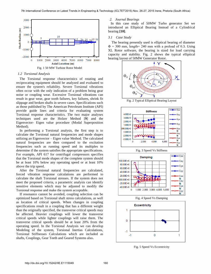
Fig. 1 50 MW Turbine Rotor Model
1.2 Torsional Analysis
The Torsional response characteristics of rotating and
reciprocating equipment should be analyzed and evaluated to
ensure the system's reliability. Severe Torsional vibrations
often occur with the only indication of a problem being gear
noise or coupling wear. Excessive Torsional vibrations can
result in gear wear, gear tooth failures, key failures, shrink fit
slippage and broken shafts in severe cases. Specifications such
as those published by The American Petroleum Institute (API)
provide guide lines and criteria for evaluating system
Torsional response characteristics. The two major analyses
techniques used are the Holzer Method [9] and the
Eigenvector- Eigen value procedure (Modal Superposition
Method).
In performing a Torsional analysis, the first step is to
calculate the Torsional natural frequencies and mode shapes
utilizing an Eigenvector – Eigen value Method. The calculated
natural frequencies are then compared to the excitation
frequencies such as running speed and its multiples to
determine if the system satisfies the appropriate specifications.
For example, API 617 for centrifugal compressors specifies
that the Torsional mode shapes of the complete system should
be at least 10% below any operating speed or at least 10%
above the trip speed.
After the Torsional natural frequencies are calculated,
forced vibration response calculations are performed to
calculate the shaft Torsional stresses. If the system does not
meet the proposed criteria, a parametric analysis can identify
sensitive elements which may be adjusted to modify the
Torsional response and make the system acceptable.
If resonance cannot be avoided, coupling selection can be
optimized based on Torsional shaft stress calculations, as well
as location of critical speeds. When changes in coupling
specifications result in a coupling that has a different weight
than the originally specified, the transverse critical speeds may
be affected. Heavier couplings will lower the transverse
critical speeds while lighter couplings will raise them. The
transverse critical speeds should be at least 20% from the
operating speed. In the Torsional Analysis we can develop
Modeling of the system, Torsional Inertias Calculations,
Torsional Stiffnesses Calculations which are included as
shafts, Couplings, Gear Teeth and Geared Systems also.
2. Journal Bearings
In this case study of 50MW Turbo generator Set we
introduced an Elliptical Bearing Instead of a Cylindrical
bearing [10].
3.1 Case Study
The bearing presently used is elliptical bearing of diameter
Φ = 300 mm, length= 240 mm with a preload of 0.3. Using
XL Rotor software, the bearing is sized for load carrying
capacity and stability. Fig. 2 shows the typical elliptical
bearing layout of 50MW Generator Rotor.
Fig. 2 Typical Elliptical Bearing Layout
Fig. 3 Speed Vs Stiffness
Fig. 4 Speed Vs Damping
Fig. 5 Speed Vs Eccentricity
7th International Conference on Latest Trends in Engineering & Technology (ICLTET'2015) Nov. 26-27, 2015 Irene, Pretoria (South Africa)
http://dx.doi.org/10.15242/IIE.E1115049 160

Table 1 shows the bearing pad parameters.
Table 2 shows the Lubricant properties, bearing length,
diameter, oil holes etc.,
Table 3 shows Speed Vs Eccentricities and load carrying
capacity values.
Table 4 shows Speed Vs Stability, power losses in bearings,
temperature rise in bearings.
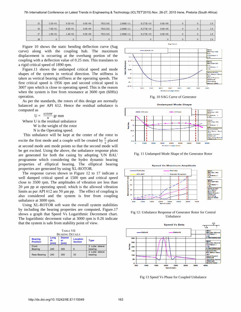
Table 5 shows Speed Vs Bearing dynamic properties for rotor
dynamic calculations and two charts i.e., Speed Vs Stiffness
shown in Fig.3 and Speed Vs Damping in Fig. 4 and
eccentricities plot are shown in Fig. 5.
TABLE I
BEARING PAD PARAMETERS
TABLE II
PROPERTIES OF A LUBRICANT
XLPocket Spreadsheet for Fixed Lobe Bearing Coefficients
Title: Conmec IR MGGB-633 OEM Pressure Dam Bearing **pdb.xls**
jcn/rmt 30August2005
Click on Cell then
Output File Names
TGSAT
Viscosity Option
0
Press Alt-F1 for Help
Selected Lubricant
Operating Film T 65.6
oC
Operating Viscosity 16.74
cp
Lubricant Ref Ta 40.0 oC Operating Density 0.85 gm/cm
3
Lubricant Ref Tb 100.0 oC Number of Visc Iter 2 --
Lubricant Ref Va 204.0 SSU Number of Holes 2 --
Lubricant Ref Vb 47.0 SSU Inlet Hole Type
0.00E+00
Lubricant Ref SGa 0.859 -- Inlet Hole Length 12.7 mm
Lubricant Ref SGb 0.826 -- Inlet Hole Width 6.35 mm Lubricant API Grav 30.6 -- Inlet Hole Diameter 2.54 mm
Journal Diameter 300.00 mm Weep Hole Type
1.00E+00
Bearing Length 240.00 mm Weep Hole Depth 0.762 mm
Diametral Clearance 0.3500 mm
Weep Hole Chamfer 45
degrees
Gravity Load 90,742 N Weep Hole Radius 0 mm First Critical Speed 1862 rpm Oil Inlet T
48.9
oC
Ecc X Initial Guess 0 -- Supply Pressure 0.138 MPa
Ecc Y Initial Guess 0 -- Horz or Vert Flag
0
Hot Oil Carry Over 60
percent
Hot Shaft T
0
oC
Pressure Field Flag
0
Brg Housing P 0 MPa
K and C File Format 1
TABLE III
SPEED & LOAD CARRYING CAPACITIES VALUES
Speed Somm
Ecc X Ecc Y
Epp Psi W Resultant W Res
Angle Loading P Max
P Max
Angle
rpm -- -- -- -- degrees Newtons degrees MPa MPa Degrees
4,000 0.185 0.3160039 0.0392684 0.31843441 97.0835794 90742 270 1.26029884 4.00565441 268.4
3,500 0.182 0.3292312 0.0346524 0.3310498 96.0084008 90742 270 1.26029884 3.92016368 270
3,000 0.1757 0.3444204 0.0282091 0.34557368 94.6822512 90742 270 1.26029884 3.84501457 271.6
2,000 0.1519 0.3830 0.0057 0.38301789 90.8454106 90742 270 1.26029884 3.74504557 278
1,000 0.1049 0.4329 -0.0604 0.43710028 82.057802 90742 270 1.26029884 3.92154256 281.2
500 0.06573 0.4443 -0.1587 0.47178104 70.3397197 90742 270 1.26029884 4.46620125 281.2
TABLE IV
BEARING STABILITY VALUES
Speed Stab Thres Stable? SurfaceV PwrLoss Drain Flow T Max Min H Min H Angle
rpm rpm -- m/s kW lpm oC mm Degrees
4,000 3816.8 0 62.81928 67.9671569 4.11E+01 128.88889 0.077216 303.51
3,500 3848.1 0 54.98592 53.3148845 3.77E+01 121.66667 0.075184 306.7
3,000 3906.1 0 47.12208 40.5267688 3.39E+01 114.44444 0.072898 306.7
2,000 4086 0 31.42488 20.2596561 26.9148265 100 0.065532 306.7
1,000 4100.6 0 15.6972 6.5245488 17.5646688 83.333333 0.051054 306.7
500 3612.5 0 7.86384 2.17733514 11.8864353 72.777778 0.036068 303.51
7th International Conference on Latest Trends in Engineering & Technology (ICLTET'2015) Nov. 26-27, 2015 Irene, Pretoria (South Africa)
http://dx.doi.org/10.15242/IIE.E1115049 161
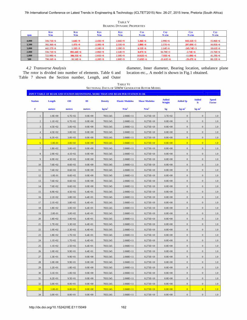
TABLE V
BEARING DYNAMIC PROPERTIES
Kxx Kxy Kyx Kyy Cxx Cxy Cyx Cyy
rpm N/m N/m N/m N/m N-s/m N-s/m N-s/m N-s/m
4,000 316.71E+6 1.64E+9 -2.43E+9 2.66E+9 5.46E+6 2.99E+6 843.32E+3 15.86E+6
3,500 392.36E+6 1.47E+9 -2.30E+9 2.51E+9 5.80E+6 2.57E+6 297.89E+3 16.85E+6
3,000 442.37E+6 1.33E+9 -2.24E+9 2.39E+9 6.53E+6 2.14E+6 -245.74E+3 18.61E+6
2,000 556.71E+6 892.44E+6 -2.06E+9 2.14E+9 8.07E+6 56.70E+3 -2.74E+6 23.76E+6
1,000 722.98E+6 306.35E+6 -2.01E+9 2.10E+9 10.82E+6 -7.93E+6 -11.89E+6 41.29E+6
500 798.16E+6 -30.34E+6 -2.20E+9 2.80E+9 15.05E+6 -21.61E+6 -29.47E+6 88.22E+6
4.2 Transverse Analysis
The rotor is divided into number of elements. Table 6 and
Table 7 shown the Section number, Length, and Outer
diameter, Inner diameter, Bearing location, unbalance plane
location etc.,. A model is shown in Fig.1 obtained.
TABLE VI SECTIONAL DATA OF 50MW GENERATOR ROTOR MODEL
INPUT TABLE OF BEAM AND STATION DEFINITIONS, MORE THAN ONE BEAM PER STATION IS OK
Station Length OD ID Density Elastic Modulus Shear Modulus Added
Weight Added Ip
Added
It
Speed
Factor
# meters meters meters kg/m3 N/m2 N/m2 kg kg-m2 kg-m2
1 1.0E+00 6.7E+02 0.0E+00 7833.545 2.068E+11 8.273E+10 3.7E+02 0 0 1.0
2 1.1E+02 6.7E+02 0.0E+00 7833.545 2.068E+11 8.273E+10 0.0E+00 0 0 1.0
3 4.5E+02 3.0E+02 0.0E+00 7833.545 2.068E+11 8.273E+10 0.0E+00 0 0 1.0
4 4.5E+02 3.0E+02 0.0E+00 7833.545 2.068E+11 8.273E+10 0.0E+00 0 0 1.0
5 6.2E+01 3.0E+02 0.0E+00 7833.545 2.068E+11 8.273E+10 0.0E+00 0 0 1.0
6 1.0E-01 3.0E+02 0.0E+00 7833.545 2.068E+11 8.273E+10 0.0E+00 0 0 1.0
7 1.8E+02 3.0E+02 0.0E+00 7833.545 2.068E+11 8.273E+10 0.0E+00 0 0 1.0
8 2.9E+02 4.1E+02 0.0E+00 7833.545 2.068E+11 8.273E+10 0.0E+00 0 0 1.0
9 6.9E+02 4.5E+02 0.0E+00 7833.545 2.068E+11 8.273E+10 0.0E+00 0 0 1.0
10 7.6E+02 8.6E+02 0.0E+00 7833.545 2.068E+11 8.273E+10 0.0E+00 0 0 1.0
11 7.6E+02 8.6E+02 0.0E+00 7833.545 2.068E+11 8.273E+10 0.0E+00 0 0 1.0
12 1.0E-01 8.6E+02 0.0E+00 7833.545 2.068E+11 8.273E+10 0.0E+00 0 0 1.0
13 7.6E+02 8.6E+02 0.0E+00 7833.545 2.068E+11 8.273E+10 0.0E+00 0 0 1.0
14 7.6E+02 8.6E+02 0.0E+00 7833.545 2.068E+11 8.273E+10 0.0E+00 0 0 1.0
15 6.9E+02 4.5E+02 6.4E+01 7833.545 2.068E+11 8.273E+10 0.0E+00 0 0 1.0
16 2.1E+02 3.8E+02 6.4E+01 7833.545 2.068E+11 8.273E+10 0.0E+00 0 0 1.0
17 2.1E+02 3.8E+02 6.4E+01 7833.545 2.068E+11 8.273E+10 0.0E+00 0 0 1.0
18 1.8E+02 3.0E+02 6.4E+01 7833.545 2.068E+11 8.273E+10 0.0E+00 0 0 1.0
19 2.0E-01 3.0E+02 6.4E+01 7833.545 2.068E+11 8.273E+10 0.0E+00 0 0 1.0
20 1.8E+02 3.0E+02 6.4E+01 7833.545 2.068E+11 8.273E+10 0.0E+00 0 0 1.0
21 1.7E+02 3.3E+02 6.4E+01 7833.545 2.068E+11 8.273E+10 0.0E+00 0 0 1.0
22 1.0E+02 2.3E+02 6.4E+01 7833.545 2.068E+11 8.273E+10 0.0E+00 0 0 1.0
23 1.8E+02 1.7E+02 6.4E+01 7833.545 2.068E+11 8.273E+10 0.0E+00 0 0 1.0
24 1.1E+02 1.7E+02 6.4E+01 7833.545 2.068E+11 8.273E+10 0.0E+00 0 0 1.0
25 1.1E+02 2.5E+02 6.4E+01 7833.545 2.068E+11 8.273E+10 0.0E+00 0 0 1.0
26 1.0E+02 9.9E+01 6.4E+01 7833.545 2.068E+11 8.273E+10 0.0E+00 0 0 1.0
27 1.3E+01 9.9E+01 0.0E+00 7833.545 2.068E+11 8.273E+10 0.0E+00 0 0 1.0
28 1.0E+00 9.9E+01 0.0E+00 7833.545 2.068E+11 8.273E+10 0.0E+00 0 0 1.0
29 1.2E+01 1.8E+02 0.0E+00 7833.545 2.068E+11 8.273E+10 0.0E+00 0 0 1.0
30 3.1E+01 1.0E+02 0.0E+00 7833.545 2.068E+11 8.273E+10 0.0E+00 0 0 1.0
31 6.2E+01 9.5E+01 0.0E+00 7833.545 2.068E+11 8.273E+10 0.0E+00 0 0 1.0
32 5.0E+01 8.0E+01 0.0E+00 7833.545 2.068E+11 8.273E+10 0.0E+00 0 0 1.0
33 1.0E-01 8.0E+01 0.0E+00 7833.545 2.068E+11 8.273E+10 0.0E+00 0 0 1.0
34 5.0E+01 8.0E+01 0.0E+00 7833.545 2.068E+11 8.273E+10 0.0E+00 0 0 1.0
7th International Conference on Latest Trends in Engineering & Technology (ICLTET'2015) Nov. 26-27, 2015 Irene, Pretoria (South Africa)
http://dx.doi.org/10.15242/IIE.E1115049 162
35 5.5E+01 9.5E+01 0.0E+00 7833.545 2.068E+11 8.273E+10 0.0E+00 0 0 1.0
36 7.9E+01 8.0E+01 0.0E+00 7833.545 2.068E+11 8.273E+10 0.0E+00 0 0 1.0
37 1.9E+01 1.4E+02 0.0E+00 7833.545 2.068E+11 8.273E+10 0.0E+00 0 0 1.0
38 0 0 0 0 0 0 0 0 0 1.0
Figure 10 shows the static bending deflection curve (Sag
curve) along with the coupling hub. The maximum
displacement is occurring at the overhang portion of the
coupling with a deflection value of 0.25 mm. This translates to
a rigid critical speed of 1890 rpm.
Figure.11 shows the undamped critical speed and mode
shapes of the system in vertical direction. The stiffness is
taken as vertical bearing stiffness at the operating speeds. The
first critical speed is 1956 rpm and second critical speed is
3007 rpm which is close to operating speed. This is the reason
when the system is free from resonance at 3600 rpm (60Hz)
operation.
As per the standards, the rotors of this design are normally
balanced as per API 612. Hence the residual unbalance is
computed as
U =
gr mm
Where U is the residual unbalance
W is the weight of the rotor
N is the Operating speed.
This unbalance will be kept at the center of the rotor to
excite the first mode and a couple will be created by
placed
at second mode anti mode points so that the second mode will
be get excited. Using the above, the unbalance response plots
are generated for both the casing by adopting 'UN BAL'
programme which considering the hydro dynamic bearing
properties of elliptical bearing. The elliptical bearing
properties are generated by using XL-ROTOR.
The response curves shown in Figure 12 to 17 indicate a
well damped critical speed at 1500 rpm and critical speed
close to 3500 rpm. The amplitudes of vibration are less than
20 μm pp at operating speed; which is the allowed vibration
limits as per API 612 are 50 μm pp. The effect of coupling is
also considered and the system is free from coupling
unbalance at 3000 rpm.
Using XL-ROTOR soft ware the overall system stabilities
by including the bearing properties are computed. Figure.17
shows a graph that Speed Vs Logarithmic Decrement chart.
The logarithmic decrement value at 3000 rpm is 0.26 indicate
that the system is safe from stability point of view.
TABLE VII BEARING DETAILS
Bearing Position
Length (mm)
Diameter (mm)
Location Section
Type
Front Bearing 240 300 6
2 Lobe sleeve bearing
Rear Bearing 240 300 33 2 Lobe sleeve bearing
Fig. 10 SAG Curve of Generator
Fig. 11 Undamped Mode Shape of the Generator Rotor
Fig 12: Unbalance Response of Generator Rotor for Central
Unbalance
Fig 13 Speed Vs Phase for Coupled Unbalance
7th International Conference on Latest Trends in Engineering & Technology (ICLTET'2015) Nov. 26-27, 2015 Irene, Pretoria (South Africa)
http://dx.doi.org/10.15242/IIE.E1115049 163
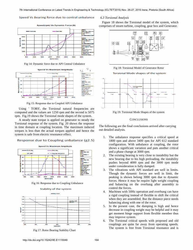
Fig 14: Dynamic force due to API Central Unbalance
Fig 15: Response due to Coupled API Unbalance
Using ' TORS', the Torsional natural frequencies are
computed and the values are 1250 rpm and the second is 5075
rpm. Fig.19 shows the Torsional mode shapes of the system.
A steady state torque is applied on generator to steady the
Torsional response of the system. Fig. 20 shows the response
in time domain at coupling location. The maximum induced
torques is less than the actual torques applied and hence the
system is safe from electric resonance effect.
Fig 16: Response due to Coupling Unbalance
Fig 17: Rotor Bearing Stability Chart
6.3 Torsional Analysis
Figure 18 shows the Torsional model of the system, which
comprises of steam turbine, coupling, gear box and Generator.
Fig 18: Torsional Model of Generator Rotor
Fig 19: Torsional Mode Shapes of the system
CONCLUSIONS
The following are the final conclusions arrived after carrying
out detailed analysis.
1. The unbalance response specifies a critical speed at
1800 rpm and above 3400 rpm for API 612 standard
configuration. With unbalance at coupling, the rotor
shows a significant variation and puts another critical
and a phase change at 3000 rpm.
2. The existing bearing is very close to instability but the
new bearing due to his high preloading, the instability
pushes beyond 4000 rpm and the 3000 rpm mode
under consideration is fully damped.
3. The vibrations with API standard are well in limits.
Though the dynamic forces are well in limit, the
peaking is shown belong 3000 rpm due to dynamic
forces. Hence it may be require light weight coupling
and balancing on the overhang after assembly to
control the forces.
4. Machines with 50Hz operation and overhung can have
a rigid coupling instead of flexible to shift the critical
when they are assembled. But the distance piece needs
balancing along with one of the rotor.
5. In the present case, the damping is high and hence
decrease in coupling weight may be helpful and it may
get moment hinge support from flexible member thus
may improve system.
6. The Torsional critical speeds with proposed and old
couplings are quite far away from operating speeds.
The system is free from Torsional resonance and is
7th International Conference on Latest Trends in Engineering & Technology (ICLTET'2015) Nov. 26-27, 2015 Irene, Pretoria (South Africa)
http://dx.doi.org/10.15242/IIE.E1115049 164
safe with both couplings. The Torsional critical speeds
are 1250 cpm and 5075 cpm.
7. The rigid and damped critical speeds are at 2000 rpm
and at 3000 rpm along with coupling. There is slight
variation in critical speed with the weight of the
coupling. With 560 Kgs weight the critical speed is
1890 rpm and 3000 rpm and with modified coupling
there is increase in critical speed of 200 to 300 rpm.
8. The mode shapes are sensitive to bearing stiffness and
coupling moment. With lower bearing stiffness the
modes are under control and in all aspects the coupling
plays dominant rule. With higher stiffness the exciter
vibrations will be significant.
REFERENCES
[1] Rao, J.S., "Rotor Dynamics", Wiley Eastern Limited, New Delhi, 1983. [2] Chree, C., "The Whirling and Transverse Vibrations of Rotating Shafts",
Phil. Mag. 7, 1904, p.504.
http://dx.doi.org/10.1080/14786440409463146 [3] Lowey, R.G. and Piarulli, V.J., "The Dynamics of Rotating Shafts",
SUM No.4, The Shock and Vibration Information Center, Washington,
D.C., 1970. [4] Campbell Wilfred. “Protection of Steam Turbine Disk Wheels from
Axial Vibration", Trans. ASME., Vol. 46, 1924, pp. 31-160.
[5] Bansal, P.N. and Kirk, R.G., "Stability and Damped Critical Speeds of Rotor Bearing Systems", ASME Paper No. 75-DET-57.
[6] Darlow, M.S., Smalley, A.J. and Ogg.J.,"Critical Speeds and Response
of Large Vertical Pump", ASME, Paper No. 78-PUP-34. [7] Gunter, E.J. and DeChowdhury, P.,"Dynamic Stability of Flexible Rotor
Systems", ME-4040-104-700, University of Virginia, Charlottes Ville
1970. [8] Prohl. M.A., "a General Method for Calculating Critical Speeds of
Flexible Rotors", Trans. ASME, J. Appl. Mechanics, Vol.12, No.3,
Sept. 1945, pp. A142-A148. [9] Holzer, H.,"Die Berechnung der Drehswingunen", Springer Verlag
OHG, Berlin, Published by J.Edwards, inc.Ann ABN Mich. 1921. [10] W.J.Chen & E.J.Gunter., “DyRoBeS ( Dynamics of Rotor Bearing
Systems) is a powerful and complete Rotor Dynamics and Bearing
Analysis program based on Finite Element Analysis", A Comprehensive
Rotor Dynamics book, 1985.
7th International Conference on Latest Trends in Engineering & Technology (ICLTET'2015) Nov. 26-27, 2015 Irene, Pretoria (South Africa)
http://dx.doi.org/10.15242/IIE.E1115049 165