Rotating exactly, using · EXACT reserves the right to make changes arising from constant product...
34
www.exactmachinery.com ■ No.418, Shueiyuan Rd., Fengyuan Dist., Taichung City 420, TAIWAN. ■ T E L : 886-4-25158290 ■ FAX : 886-4-25158291 ■ E-mail:[email protected] ■ Web site: www.exactmachinery.com Rotating exactly, using Rheinland CERTIFED ® ISO 9001:2015 ID 9105073525
Transcript of Rotating exactly, using · EXACT reserves the right to make changes arising from constant product...

www.exactmachinery.com
■ No.418, Shueiyuan Rd., Fengyuan Dist., Taichung City 420, TAIWAN. ■ TEL: 886-4-25158290
■ FAX : 886-4-25158291 ■ E-ma i l : i n fo@exac tmach ine ry.com ■ Web site: www.exactmachinery.com
Rotating exactly, using
RheinlandCERTIFED
®
ISO 9001:2015ID 9105073525

Research and Development
A l l k e y c o m p o n e n t s a r e
manufactured in or state of the
art workshops to achieve and
maintain the highest qual ity
possible.
A l l c o m p o n e n t s a n d s u b -
assembl ies are meticulously
checked prior to and throughout
the assembly process.
Tables are assembled and tested
under str ict enforcement of
standardized procedures based
upon ISO 9001.
Parts Manufacturing and Assembly
EXACT is a professional global supplier with a robust technological R&D foundation,
compl imented by a qual ity minded workforce with "state of the art" manufacturing
equipment and a stringent quality control department, this, plus a professional distribution
network all of whom are committed to solution finding and complete customer satisfaction.
EXACT top quality CNC Rotary Tables and Indexing Tables are used in a wide variety of
applications in the Medical, Aerospace and Automotive industries, in the manufacturing of
Oil & Water pipeline valves and equipment and in Job Shops where flexibility is required.
Plus many others.
Throughout over 2 decades of experience, EXACT has continuously developed new
and innovates products to improve the manufacturing processes and productivity for
our customers. With top quality products and professional support, our customers are
"Rotating exactly, using EXACT!"
E x a c t M a c h i n e r y h a s a
special ized R & D team who
work closely with customers
in developing products with
t h e o p t i m u m p e r f o r m a n c e
characteristics to ult imately
create the ideal solut ion to
m e e t s p e c i f i c a p p l i c a t i o n
needs , du r i ng wh i ch So l i d
Works 3D software and finite
element analysis programs are
used.
The mechanical structures are
simulated and analyzed thus
the most demanding technical
specifications are prequalified
and the design data can be
passed onto the customer in
the fastest possible way.
Rotating exactly, using
Innovation.Quality.ProfessionalismInnovation.Quality.Professionalism

●Hardness Tester Instrument
● 2D measuring machines
● Surface Roughness Measuring Instrument
● Agilent Laser Angular Position Measurement System
● Zeiss 3D Measuring Machines
● Worm Wheel Measuring Instrument
● Optical Auto-col l imator
Quality Control and Final InspectionOur quality procedures not only guarantee a
precise assembly, but also verifies that each
component is manufactured perfectly within
specification, by using the most up to date
3D measuring devices.
Each Table has the positioning accuracy and
repeatability checked in accordance to ISO
230-2 standards, either by using an optical
auto-collimator or a laser measuring system
depending upon table type.
The laser angular measurement executes
measurement at any angle which will work
out the real involute teeth tolerance
EXACT MACHINERY CO., LTD.

16
50
18
19
51
22
21
52
8
12
54
56
14
58
31
60
26
44
42
49
34
28
45
38
30
48
40
NOTE:The information contained in this product catalogue is based on detai l avai lable at the t ime of pr int ing; EXACT reserves the right to make changes arising from constant product development without advance notice
NCT-TCNC Rotary Table fitted to a Manual Tilting Base
NCT-LMega Central Hole CNC Rotary TableTable
ERTCNC Tilting / Rotary Table
TRTCNC Tilting / Rotary Table
TRT-TNCNC Multi Spindle Tilting Rotary Table
NCTCNC Vertical / Horizontal Table
NCT-RBCNC Table with a rear mounted motor
NCT-TNCNC Multi Spindle Table
NCT-HBCNC Heavy Duty Rotary Table
HCCNC Vertical / Horizontal Table, Hydraulic Hirth Gear Clamping
HC-HCNC Horizonal Table, Hydraulic Hirth Gear Clamping
HC-HBCNC Heavy Duty Table, Hydraulic Hirth Gear Clamping
CTHydraulic Horizontal Index Table
CT-VHydraulic Vertical Index Table
CT-WS-DCNC Vertical / Horizontal "Built-in" Table, Hydraulic Hirth Gear Clamping
MBTManual Rotation, Pneumaticand Hydraulic Clamping
NCT-HP Auto-Pallet Changer with aCNC Rotary Table
HC-HPAuto-Pallet Changer with an Indexing Table
HC-1250HPWorktable with a built-in Pallet Receiver
EDSNC Rotary Table with Direct Drive Motorand Hydraulic Clamping
MTS and MTS-BManual Tailstock
ATS and ATS-BAuto Tailstock,Pneumatic or HydraulicActuaction
BTSHeavy Duty Tailstock
DNSAC Digital, Single Axis Controller
DNS-AAC Digital, Single Axis Controller
Hirth Coupling Gear2 piece and 3 piece coupling set
Accessories
CONTENTSRotary Table
Indexing Table, Non-Lifting,Motor Driven with Hirth Gear
Indexing Table, Non-Lifting, Rack& Pinion Drive with Hirth Gear
Manual Indexing Table, with Hirth Gear
Automatic Pallet Changer withWorktable
Accessories
NC Rotary Table with Torque Motors

EXACT MACHINERY CO., LTD. www.exactmachinery.com6 7
NCT/TRT/ERT CNC Rotary Tables withWorm & Wheel Drive
ERT
NCT-HB
TRT
NCT-TN
NCT-T
NCT
LARGE CONTACT SURFACESASSURES THE ULTIMATE INPOWERFUL PERFORMANCE ANDSMOOTH MOTION
The NCT series of tables expand Machining Centers production capacity. Mounted in either a horizontal or vertical plane, these tables are used to add 4th or 5th axis capability. Inside the rotary tables, the worm shaft and worm gear system decide the tables' accuracy and life. Through the strict inspection and in-house machining of the worm system, Exact guarantees products optimal performance and high dynamic durability.
● Wide range of types and sizes
● Robust and wear-resistant design
● Outstanding rotation torque
● High dynamic accuracy and longevity
● Easy installation and maintenance
● MaterialsWorm gear: Special high-tensile aluminum-brass
equal in strength to a steel alloy.
Worm shaft: Hardened alloy steel
● High Rotation Torque The combination of brass and alloy steel offers
less friction. Motor torque is transferred
efficiently. High class material worm system
guarantees high torque transmission.
● Large Worm Gear The worm gear with a large pitch diameter
creates a large engagement area and less pressure
on the contact surface, resulting in resistance
against wear.
Our massive, 360° low volume, high speed Hydraulic Clamping
System is immediately behind the table to ensure maximum
rigidity during machining operations.
A solid and sealed clamping structure maintains maximum
holding power while keeping contaminates out.
Only a small amount of hydraulic fluid is required to achieve an
optimum clamping force, the source of which can be from a mini
hydraulic pump unit or an air-over-oil intensifier; both are
options.
Rugged, 360° Surround Clamping
Hydraulic Power
Close to Table Top
360° SurroundClamp
gear

EXACT MACHINERY CO., LTD. www.exactmachinery.com8 9
NCT
CNC Rotary Table NCT
CNC Rotary Table
NCT tables are designed with axial - radial bearings to provide excellent load and thrust capabil it ies. The hydraulic clamp produces a massive holding power and the housings withstand any twisting or flexing. The large center bore series provides for added flexibil ity when adding work holding devices.●Suitable for Vertical and Horizontal mounting
NCT tables are designed with axial - radial bearings to provide excellent load and thrust capabil it ies. The hydraulic clamp produces a massive holding power and the housings withstand any twisting or flexing. The large center bore series provides for added flexibil ity when adding work holding devices.●Suitable for Vertical and Horizontal mounting
Model NCT-125R(L) NCT-170R(L) NCT-200R(L) NCT-250R(L) NCT-320R(LV)NCT-B-320RV(LV)
Table diameter (mm) Ø125 Ø170 Ø200 Ø250 Ø320Diameter of "Pilot" bore (mm) Ø40H7 Ø50H7 Ø60H7 Ø50H7 Ø60H7/Ø110H7
Diameter of through hole (mm) Ø25 Ø30 Ø40 Ø40 Ø46/Ø100Overall height with table top horizontal (mm) 150 190 195 200 230Center height with table top vertical (mm) 110 135 135 170 210Width of T slots (mm) 12H7 12H7 12H7 12H7 14H7
Width of alignment key in mounting base (mm) 14h7 14h7 18h7 18h7 18h7
Clamp operation pressure (Hydraulic) (bar) 35 35 35 35 35 Ambient temperature (°C) 18°~40°Minimum input increment (degree) 0.001° 0.001° 0.001° 0.001° 0.001°Gear ratio, Motor to Table Top 1/90 1/90 1/90 1/120 1/120
Table speed(motor 3000 r.p.m) 33.3 33.3 33.3 25 25(motor 4000 r.p.m) 44.4 44.4 44.4 33.3 33.3
Servo motor(Optional)
FANUC α2i α4i α4i α8i α12iMITSUBISHI HF-105T HF-54T HF-54T HF-104S HF-204SSIEMENS 1FK7042 1FK7060 1FK7060 1FK7063 1FK7083
Indexing accuracy (sec of arc) 60’’ 20’’ 20’’ 15’’ 15’’Repeatability (sec of arc) 4’’ 4’’ 4’’ 4’’ 4’’
Rotation torque (kgf-m) 12 16 23 48 78 (N-m) 118 157 225 470 764
Permissible load(With table clamped)
F (kgf)(N)
6005880
8007840
10009800
140013720
170016660
FxL (kgf-m)(N-m)
15147
17167
24235
50490
85833
FxL (kgf-m) (N-m)
20196
40392
65637
85833
1101078
Permissible piecepart and fixtureweight
0° (kg) 100 150 200 250 350
90° (kg) 50 70 85 100 150
Net Weight (kg) 38 60 75 110 220
Allowable work inertia W·D2
J= ¯¯¯¯ 8(kg-m2) 0.20 0.54 1.00 1.95 4.48
* We reserve the right to make changes arising from constant product development without advance notice.
* The list of fitting servomotor, please refer to page 61.
F
L
F
F
L
W
W
Model NCT-400RVNCT-B-400RV NCT-B-500RV NCT-B-630RV NCT-B-800R NCT-B-1000R NCT-B-1200R
Table diameter (mm) Ø400 Ø500 Ø630 Ø800 Ø1000 Ø1200Diameter of "Pilot" bore (mm) Ø60H7/Ø155H7 Ø200H7 Ø250H7 Ø295H7 Ø305H7 Ø330H7
Diameter of through hole (mm) Ø51/Ø150 Ø170 Ø210 Ø250 Ø260 Ø280Overall height with table top horizontal (mm) 250 300 325 380 430 550Center of height with table top vertical (mm) 250 310 400 480 650 750Width of T slots (mm) 14H7 18H7 18H7 22H7 22H7 22H7
Width of alignment key in mounting base (mm) 18h7 18h7 18h7 22h7 22h7 22h7
Clamp operation pressure (Hydraulic) (bar) 35 35 35 35 35 35 Ambient temperature (°C) 18°~40°Minimum input increment (degree) 0.001° 0.001° 0.001° 0.001° 0.001° 0.001°Gear ratio, Motor to Table Top 1/180 1/180 1/180 1/360 1/360 1/720Table speed (motor 3000 r.p.m) 16.6 16.6 16.6 8.3 8.3 4.16
Servo motor(Optional)
FANUC α12i α12i α22i α22i α22i α30iMITSUBISHI HF-204S HF-204S HF-354S HF-354S HF-354S XSIEMENS 1FK7083 1FK7083 1FK7101 1FK7101 1FK7101 1FK7103
Indexing accuracy (sec of arc) 15’’ 15’’ 15’’ 15’’ 15’’ 15’’Repeatability (sec of arc) 4’’ 4’’ 4’’ 4’’ 4’’ 4’’
Rotation torque (kgf-m) 170 240 420 520 600 800 (N-m) 1666 2352 4116 5096 5880 7840
Permissible load(With table clamped)
F (kgf)(N)
200019600
230022540
260025480
280027440
490048020
600058800
FxL (kgf-m)(N-m)
1801764
2502450
4504410
5505390
6506370
180017640
FxL (kgf-m) (N-m)
1801764
2502450
4003920
7006860
180017640
200019600
Permissible piecepart and fixtureweight
0° (kg) 500 800 1000 1400 3000 5000
90° (kg) 200 350 400 600 1200 2000
Net Weight (kg) 300 450 820 1600 2800 4000
Allowable work inertia W·D2
J= ¯¯¯¯ 8(kg-m2) 10.00 25.00 49.61 112.00 375.00 900.00
* We reserve the right to make changes arising from constant product development without advance notice.
* The list of fitting servomotor, please refer to page 61.
F
L
F
F
L
W
W
W
ØD
W
ØD
Guaranteed accuracy
1 2 3 4 5 6 7
NO Inspection items NCT-125 NCT-170NCT-200
NCT-250NCT-B-320
NCT-B-400NCT-B-500
NCT-B-630NCT-B-800
NCT-B-1000NCT-B-1200
1 Concentricity of center hole 0.01 0.01 0.01 0.01 0.01 0.012 Perpendicularity of table with guide block Per total table length 0.02 0.02 0.02 0.02 0.03 0.03
3 Height difference of both center lines of Rotary table and tailstock
Per 300 mm length 0.02 0.02 0.02 0.02 0.02 0.02
4 Perpendicularity of table top to frame bottom Per total table length 0.02 0.02 0.02 0.02 0.03 0.035 Table top flatness Per total table length 0.015 0.015 0.015 0.015 0.03 0.036 Parallelism of table top to frame bottom 0.01 0.01 0.01 0.015 0.02 0.02
7 Parallelism between table surface and frame bottom
Per total table length 0.02 0.02 0.02 0.02 0.03 0.03

www.exactmachinery.com10 11EXACT MACHINERY CO., LTD.
NCT-400RV
NCT-B-500RV
NCT-B-630RV
NCT-B-800R
NCT-B-1000R NCT-B-1200R
NCT-125R
NCT-320R
NCT-B-320RV
NCT-170R
NCT-200R
NCT-250R
300
60
Ø50
0
290
40
Ø300
310
255 255
18
545
933
318 70
Ø260
565 Ø17
0
Ø20
0
282 18
325
65
Ø63
0
310 40
Ø330
400
320 320
18
Ø290
352
1050
308 70
720 Ø21
0
308 17
Ø25
0
Ø25
0
353 27
Ø29
5
380
316
370 410 410410
4101300
410 70
820
22
64
50
895
480
495 63
5
100
415
Ø80
0
1000
260
305
380 50
410
430
410 50
650
510 510
444
1160
22
1490
510 40070
280
330
535 15
Ø12
00
430 120
510
750
610
1360
12201690
23
467
550 50
150
610 610 400
1010
1620
304
22
70
100
Ø40
0
Ø15
0
Ø60
234 16
245
250750
205
20518
205
225 320545
206 44
35
455
344
111
205
250
7
✽ Optional accessories
DNS controller Tailstock 3-jaw chuckwith sub plate Encoder PHC
Taper Support
*(p.54) *(p.50) *(p.52) *(p.60) *(p.61) *(p.60)
◎ Standard accessories
Block nuts Hangers
◎ ◎
190
156
181
25
34
170
30
50
94
225
7 20
135
500
10 275
220 220 60
90
90 110
14
177 13
250
40
50
120
150
200
300
170
20 130 130
18
7
130
165 35
30
190
285 265
187 13
610
60
300
10
150
118 200 205 83
235
5
20 190
80
20
80 100
14
110
715
32
488
150
25
40
15135
70
125
34161195
Ø20
025
185 18105 11510
713
510
524
0
240 220 60520
827
3
Ø104 Ø60
185 10
Ø40
Ø32
030
230187 43
210
385
385
165
1021
07 2
165 195
669504
309
165 21018
Ø10
0
Ø11
0
214 16
Ø46
Ø60
204 26
30Ø
320
230187 43
210
380
210
7
380
5
170
175
685450 60
220 230
175 19018

EXACT MACHINERY CO., LTD. www.exactmachinery.com12 13
NCT-125RB
NCT-170RB
NCT-200RB
NCT-250RB
NCT-RB CNC Rotary Table with rear mounted motor
NCT-RB Tables have a rear mounted drive motor, especially suited for use on compact machines and where the workspace is limited. High rigidity and excellent thrust force capabilities due to its optimal structure design.
Model NCT-125RB NCT-170RB NCT-200RB NCT-250RBTable diameter (mm) Ø125 Ø170 Ø200 Ø250Diameter of "Pilot" bore (mm) Ø40H7 Ø50H7 Ø60H7 Ø50H7
Diameter of through hole (mm) Ø25 Ø30 Ø40 Ø40Center height with table top vertical (mm) 110 135 135 170Width of T slots (mm) 12H7 12H7 12H7 12H7
Width of alignment key in mounting base (mm) 14h7 14h7 18h7 18h7
Clamp operation pressure (Hydraulic) (bar) 35 35 35 35 Ambient temperature (°C) 18°~40°Minimum input increment (degree) 0.001° 0.001° 0.001° 0.001°Gear ratio, Motor to Table Top 1/90 1/90 1/90 1/120
Table speed(motor 3000 r.p.m) 33.3 33.3 33.3 25(motor 4000 r.p.m) 44.4 44.4 44.4 33.3
Servo motor(Optional)
FANUC α2i α4i α4i α8iMITSUBISHI HF-105T HF-54T HF-54T HF-154SSIEMENS 1FK7042 1FK7060 1FK7060 1FK7063
Indexing accuracy (sec of arc) 60’’ 20’’ 20’’ 15’’Repeatability (sec of arc) 4’’ 4’’ 4’’ 4’’
Rotation torque (kgf-m) 12 16 23 48 (N-m) 118 157 225 470
Permissible load(With table clamped)
F (kgf)(N)
6005880
8007840
10009800
140013720
FxL (kgf-m)(N-m)
15147
17167
24235
50490
FxL (kgf-m) (N-m)
20196
40392
65637
85833
Permissible piece partand fixture weight 90° (kg) 50 70 85 100
Net Weight (kg) 60 85 100 140* We reserve the right to make changes arising from constant product development without advance notice.
* The list of fitting servomotor, please refer to page 61.
F
L
F
F
L
✽ Optional accessories
DNS controller Tailstock 3-jaw chuckwith sub plate Encoder PHC
Taper Support
*(p.54) *(p.50) *(p.52) *(p.60) *(p.61) *(p.60)
◎ Standard accessories
Block nuts Hangers
◎ ◎
275
7
110
175
14
80 100
280
372
32
275
139 145
284 20
219 12183
125
25
40
135 15
427
292 170
25
177 181
358
190
3460
237
292
135
7
195
90 110
315
14
30
50
177 13
40
185 10
60
412
34
162156
60
290
200
185157
342 25
290
195
18
105 115
310
135
7
40
50
187 13
215
350
130 130
18
365
170
7
250
35
16816060
350
163 190
353
30
423
W

EXACT MACHINERY CO., LTD. www.exactmachinery.com14 15
NCT-125R-T2
NCT-125R-T4
NCT-170R-T2 NCT-170R-T3
NCT-200R-T2
NCT-250R-T2
NCT-125R-T3
NCT-TNCNC Multi Spindle Rotary Table
NCT-TN allow multiple piece parts and multi-face machining for greater productivity. The one-piece housing and a single worm shaft ensures optimum rigidity, accuracy and agility.
Model NCT-125R-T2/T3/T4
NCT-170R-T2/T3 NCT-200R-T2 NCT-250R-T2
Table diameter (mm) Ø125 Ø170 Ø200 Ø250Diameter of "Pilot" bore (mm) Ø40H7 Ø50H7 Ø60H7 Ø50H7
Diameter of through hole (mm) Ø25 Ø30 Ø40 Ø40Distance between table centers (mm) 150 200 250 300Overall height with table top horizontal (mm) 160 190 195 200Center height with table top vertical (mm) 110 135 135 170Width of T slots (mm) 12H7 12H7 12H7 12H7
Width of alignment key in mounting base (mm) 18h7 14h7 18h7 18h7
Clamp operation pressure (Hydraulic) (bar) 35 35 35 35 Ambient temperature (°C) 18°~40°Minimum input increment (degree) 0.001° 0.001° 0.001° 0.001°Gear ratio, Motor to Table Top 1/90 1/90 1/90 1/120
Table speed(motor 3000 r.p.m) 33.3 33.3 33.3 25(motor 4000 r.p.m) 44.4 44.4 44.4 33.3
Servo motor(Optional)
FANUC α4i/α8i α8i α8i α8iMITSUBISHI HF-54T/HF-104S HF-154T HF-154T HF-154SSIEMENS 1FK7060/1FK7063 1FK7063 1FK7063 1FK7063
Indexing accuracy (sec of arc) 60’’ 40’’ 40’’ 30’’Repeatability (sec of arc) 4’’ 4’’ 4’’ 4’’
Rotation torque (kgf-m) 12 16 23 48 (N-m) 118 157 225 470
Permissible load(With table clamped)
F (kgf)(N)
6005880
8007840
10009800
140013720
FxL (kgf-m)(N-m)
15147
17167
24235
50490
FxL (kgf-m) (N-m)
20196
40392
65637
85833
Permissible piece partand fixture weight
0° (kg) 100 150 200 250
90° (kg) 50 70 85 100
Net Weight (kg) 70 / 90 / 110 115 / 135 140 195
Allowable work inertia W·D2
J= ¯¯¯¯ 8(kg-m2) 0.20 0.54 1.00 1.95
* We reserve the right to make changes arising from constant product development without advance notice.
* The list of fitting servomotor, please refer to page 61.
F
L
F
F
L
✽ Optional accessories
DNS controller Tailstock 3-jaw chuckwith sub plate Encoder PHC
Taper Support
*(p.54) *(p.50) *(p.52) *(p.60) *(p.61) *(p.60)
◎ Standard accessories
Block nuts Hangers
◎ ◎
160
18
18
2080
155
32
125
70
673
150 116
250
224
330
18
7
11019
0
83
25
40
70
873
150
480
18
7
11019
0
150 116 274
255
83
145 15
233
160
190
110
7
32 150 150 150
942
274
255
116
20155
238
125
25
40
145 1570
630
18
94
170
25
181
245
225
135
210
110 200
720
110 280
265
420
14
7
156 34
30
50
177
1394
920
14310
620
265
10
110
225
135
7
200 200 110 300
40
60
185 10
200
25185
161 34
104
840
105 250 135
18
470
230
240
135
7
280
265
60
200
165
190
30
300
18
280
560
187 13
130 130 265 60300
930
170
7
250
40
150
50
W
W
W
ØD

EXACT MACHINERY CO., LTD. www.exactmachinery.com16 17
ERT-250
ERT-350
ERT-500
ERTCNC Tilting Rotary TableERT series of Tilting Rotary Table enables accurate and productive machining. These tables are designed so that the surface of the table top is on the centerline of the tilting axis, for a greater piece part capacity, easier programming and less interference in the work zone.
Tilting angle of tilting axis -110°~ +20°
Tilting angle of tilting axis -110°~ +20°
Tilting angle of tilting axis -110°~ +20°
T-slots
T-slots
T-slots
Model ERT-250 ERT-350 ERT-500Table diameter (mm) Ø250 Ø350 Ø500Diameter of "Pilot" bore (mm) Ø70H7 Ø100H7 Ø200H7
Diameter of through hole (mm) Ø50 Ø60 Ø170Table height at 0° (mm) 315 390 520Width of T slots (mm) 12H7 14H7 18H7
Width of alignment key in mounting base (mm) 14h7 18h7 18h7
Clamp operation pressure (Hydraulic) (bar) 35 35 35Ambient temperature (°C) 18°~40°Axis Rotary Tilting Rotary Tilting Rotary Tilting
Minimum input increment (degree) 0.001° 0.001° 0.001° 0.001° 0.001° 0.001°Gear ratio, Motor to Table Top 1/120 1/180 1/120 1/180 1/180 1/360Table speed (motor 3000 r.p.m) 25 16.6 25 16.6 16.6 8.3
Servo motor(Optional)
FANUC α8i α8i α8i α12i α12i α22iMITSUBISHI HF-104S HF-104S HF-104S HF-204S HF-204S HF-354SSIEMENS 1FK7063 1FK7063 1FK7063 1FK7083 1FK7083 1FK7101
Indexing accuracy (sec of arc) 15’’ 45’’ 15’’ 45’’ 15’’ 90’’Repeatability (sec of arc) 4’’ 8’’ 4’’ 8’’ 4’’ 8’’Tilting range ( Horizontal = 0°) -110°~+20° -110°~+20° -110°~+20°
Rotation torque (kgf-m) 82 102 200 200 240 240
(N-m) 803 1000 1960 1960 2352 2352
Permissible load(With tableclamped)
F (kgf) 1000 1500 2300(N) 9800 14700 22540
FxL (kgf-m) 82 200 350(N-m) 804 1960 3430
FxL (kgf-m) 102 200 710(N-m) 1000 1960 6958
Permissiblepiece part andfixture weight
0° (kg) 120 150 500
0~90° (kg) 70 100 300
Permissiblework moment WxL
(kgf-m) 5 15 51(N-m) 49 147 500
Net Weight (kg) 900 1200 2000
Allowable work inertia
W·D2
J= ¯¯¯¯ 8(kg-m2) 0.94 2.30 15.63
* We reserve the right to make changes arising from constant product development without advance notice.
* The list of fitting servomotor, please refer to page 61.
✽ Optional accessories
DNS controller Tailstock 3-jaw chuckwith sub plate Encoder PHC x 2
Taper Support
*(p.54) *(p.50) *(p.52) *(p.60) *(p.61) *(p.60)
◎ Standard accessories
Block nuts Hangers
◎ ◎
F
FL
L
F
W
W
W
L
W
ØD

www.exactmachinery.com 19EXACT MACHINERY CO., LTD.18
TRT-TN CNC Multi Spindle Tilting Rotary Table
TRTCNC Tilting Rotary TableTRT, NC controlled 2 axis tables are suitable for larger work capacities when 5 axis machining. One piece housing structure with powerful hydraulic clamping system offers a greater clamping torque and high loading capacities. Designed for easy installation and alignment.
TRT-TN offers multi station 5 axes machining operation. This enhances the productivity for mass production.One piece frame structure offers high stability.
Model TRT-100 TRT-170 TRT-200 TRT-250 TRT-320 TRT-450Table diameter (mm) Ø90 Ø170 Ø200 Ø250 Ø320 Ø450Diameter of "Pilot" bore (mm) Ø55H7 Ø75H7 Ø75H7 Ø50H7 Ø60H7 Ø170H7
Diameter of through hole (mm) Ø35 Ø50 Ø50 Ø40 Ø46 Ø130Table height at 0° (mm) 190 303 303 320 355 435Table height at 90° tilted (mm) 233 330 330 360 420 560Table Center height at 90° tilted (mm) 135 215 215 230 255 335Width of T slots (mm) x 12H7 12H7 12H7 14 H7 14 H7
Width of alignment key in mounting base (mm) 14h7 18h7 18h7 18h7 18h7 18h7
Clamp operation pressure (Hydraulic) (bar) 5 (Pneumatic) 35 35 35 35 35 Ambient temperature (°C) 18°~40°Axis Rotary Tilting Rotary Tilting Rotary Tilting Rotary Tilting Rotary Tilting Rotary TiltingMinimum input increment (degree) 0.001° 0.001° 0.001° 0.001° 0.001° 0.001° 0.001° 0.001° 0.001° 0.001° 0.001° 0.001°Gear ratio, Motor to Table Top 1/60 1/120 1/72 1/120 1/72 1/120 1/360 1/360 1/360 1/360 1/180 1/360
Table speed(motor 3000 r.p.m) 50 25 41.6 25 41.6 25 8.3 8.3 8.3 8.3 16.6 8.3(motor 5000 r.p.m) 83.3 41.6 69.4 41.6 69.4 41.6 13.8 13.8 13.8 13.8 27.7 13.8
Servo motor(Optional)
FANUC α2i α2i α2i α8i α2i α8i α8i α8i α8i α8i α12i α12iMITSUBISHI HF-105T HF-105T HF-105T HF-154T HF-105T HF-154T HF-154T HF-154T HF-154S HF-154S HF-204S HF-204SSIEMENS 1FK7042 1FK7042 1FK7042 1FK7063 1FK7042 1FK7063 1FK7063 1FK7063 1FK7063 1FK7063 1FK7083 1FK7083
Indexing accuracy (sec of arc) 60’’ 60’’ 20’’ 60’’ 20’’ 60’’ 15’’ 60’’ 15’’ 60’’ 15’’ 60’’Repeatability (sec of arc) 4’’ 8’’ 4’’ 8’’ 4’’ 8’’ 4’’ 8’’ 4’’ 8’’ 4’’ 8’’Tilting range ( Horizontal = 0°) -20°~+110° -40°~+110° -40°~+110° -110°~+110° -110°~+110° -110°~+110°
Rotation torque (kgf-m) 8.5 8.5 16 47 16 47 47 47 78 78 170 170
(N-m) 83 83 157 460 157 460 460 460 764 764 1666 1666
Permissible load(With tableclamped)
F (kgf)(N)
3503430
8007840
8007840
10009800
180017640
250024500
FxL (kgf-m)(N-m)
15147
40392
40392
65637
85833
1801764
FxL (kgf-m) (N-m)
15147
50490
50490
55540
100980
1801764
Permissiblepiece part andfixture weight
0° (kg) 40 60 60 100 150 250
0~90° (kg) 25 40 40 50 100 150
Permissiblework moment WxL (kgf-m)
(N-m)3
29.48
78.48
78.416
156.825
24530
294
Net Weight (kg) 105 255 260 340 500 900
Allowable work inertia
W·D2
J= ¯¯¯¯ 8(kg-m2) 0.05 0.22 0.3 0.78 1.92 6.33
Model TRT-100-T2 TRT-170-T2 TRT-250-T2Table diameter (mm) Ø90 Ø170 Ø250Diameter of "Pilot" bore (mm) Ø55H7 Ø75H7 Ø50H7
Diameter of through hole (mm) Ø35 Ø50 Ø40Table height at 0° (mm) 245 303 330Table height at 90° tilted (mm) 288 330 370Table Center height at 90° tilted (mm) 190 215 240Width of T slots (mm) x 12H7 12H7
Width of alignment key in mounting base (mm) 14h7 18h7 18h7
Clamp operation pressure (Hydraulic) (bar) 5 (Pneumatic) 35 35 Ambient temperature (°C) 18°~40°Axis Rotary Tilting Rotary Tilting Rotary TiltingMinimum input increment (degree) 0.001° 0.001° 0.001° 0.001° 0.001° 0.001°Gear ratio, Motor to Table Top 1/60 1/120 1/72 1/120 1/360 1/360
Table speed (motor 3000 r.p.m) 50 25 41.6 25 8.3 8.3(motor 5000 r.p.m) 83.3 41.6 69.4 41.6 13.8 13.8
Servo motor(Optional)
FANUC α4i α4i α8i α8i α8i α8iMITSUBISHI HF-54T HF-54T HF-154T HF-154T HF-154T HF-154TSIEMENS 1FK7060 1FK7060 1FK7060 1FK7063 1FK7063 1FK7063
Indexing accuracy (sec of arc) 60’’ 60’’ 40’’ 60’’ 30’’ 60’’Repeatability (sec of arc) 4’’ 8’’ 4’’ 8’’ 4’’ 8’’Tilting range ( Horizontal = 0°) -20°~+110° -40°~+110° -110°~+110°
Rotation torque (kgf-m) 8.5 8.5 16 47 47 47 (N-m) 83 83 157 460 460 460
Permissible load(With tableclamped)
F (kgf)(N)
175 (Single table)1715
400 (Single table)3920
500 (Single table)4900
FxL (kgf-m)(N-m)
15147
40392
65637
FxL (kgf-m) (N-m)
15147
50490
55540
Permissiblepiece part andfixture weight
0° (kg) 20 (Single table) 30 (Single table) 50 (Single table)
0~90° (kg) 13 (Single table) 20 (Single table) 25 (Single table)
Permissiblework moment WxL (kgf-m)
(N-m)3
29.48
78.416
156.8Net Weight (kg) 150 325 450
Allowable work inertia W·D2
J= ¯¯¯¯ 8(kg-m2) 0.05 0.22 0.78
* We reserve the right to make changes arising from constant product development without advance notice.
* The list of fitting servomotor, please refer to page 61.
F
F
FL
FL
L
F
L
F
W
W
W
W
W
L
W
L
W
ØD
W
ØD
1 2 3 4 5 6
A
D
BC
Guaranteed inspection accuracy
NO Inspection items TRT-100 TRT-170 TRT-200 TRT-250 TRT-320 TRT-4501 Table flatness Per overall length 0.01 0.015 0.015 0.015 0.015 0.022 Table run out 0.01 0.01 0.01 0.01 0.01 0.0153 Parallelism of table top to frame bottom Per overall length 0.02 0.02 0.02 0.02 0.02 0.024 Parallelism of table top to center line Per overall length 0.02 0.02 0.02 0.02 0.02 0.025 Concentricity of center hole 0.01 0.01 0.01 0.01 0.01 0.01
6 Parallelism of table top to frame bottom guide blocks Per overall length 0.02 0.02 0.02 0.02 0.02 0.02

EXACT MACHINERY CO., LTD. www.exactmachinery.com20 21
NCT-LMega Central Hole CNC Rotary Table
✽Suitable for large workpiece machining Ø345mm very large through hole and table diameter Ø530mm is particularly good for pipeline machining.
✽Excellent for heavy loading and high accuracyRigid structure design and hydraulic clamping system.
✽Compact design
Model NCT-L-530RTable diameter (mm) Ø530Diameter of "Pilot" bore (mm) Ø400H7
Diameter of through hole (mm) Ø345Table height at 0° (mm) 250Table Center height at 90° tilted (mm) 310Width of T slots (mm) 18 H7
Width of alignment key in mounting base (mm) 18h7
Clamp operation pressure (Hydraulic) (kg/cm2) 35Ambient temperature (°C) 18°~40°Minimum input increment (degree) 0.001°Gear ratio, Motor to Table Top 1/180Table speed (motor 3000 r.p.m) 16.7Servo motor (Optional) FANUC α12iIndexing accuracy (sec of arc) 15’’Repeatability (sec of arc) 4’’
Rotation torque (kgf-m) 428 (N-m) 4200
Permissible load(With table clamped)
F (kgf)(N)
230022540
FxL (kgf-m)(N-m)
4594500
FxL (kgf-m) (N-m)
2502450
Permissible piece partand fixture weight
0° (kg) 1000
90° (kg) 500
Net Weight (kg) 450
Allowable work inertia W·D2
J= ¯¯¯¯ 8(kg-m2) 35
* We reserve the right to make changes arising from constant product development without advance notice.
* The list of fitting servomotor, please refer to page 61.
F
L
F
F
L
W
W
Layout Dimension of TRT series
Layout Dimension of TRT-TN
NCT-L-530R
Ø34
5
Ø40
0
Ø53
0
Ø444
595
310 39
097
258
40250245
284 2841518
250284 284 257
70541895
200 50
20
W
ØD
TRT-100
TRT-170
TRT-200
TRT-250
TRT-320
TRT-450
7
120
250
40
50 150
15015
431
051
960
152
731
160 160 155325800
92 100
330
230
18242
315340
485
370 13
200
300
25
150
320
46
60
193
200
307 193 183 162
300
60
808
555
845
255
100
170
170
355
230 26
18271369
500 345
420 25
450
220
170
130490620 440
36618
335
748
510
0 1725
0 35
2701060
550
263
600
60
943
170270350
310
250 21
521
543
0
TRT-100-T2 TRT-250-T2
100
136
360
225 31
045
0
140
242 154104
290
9916
7 190
30
2019
035
0
84
28340 298
885
14
Ø35
0-0.018
+0.039 0
Ø55Ø90
101343 180 362
15480
Ø90+0.03 0 Ø55+0.03
0
Ø35+0.039 0
5
210
120
280140
100125
350
14 0-0.018
150
35
30015
0
731
Ø10
0
519
6220
9
380
325 160Ø250 Ø250 155
9224
0 340
Ø50
Ø40
490 392 73
Ø40
3001100
310
+0.018-0
18 +0-0 .01
Ø50+0.018-0
1512
281 117
92
33 305
686
Ø75
90°
Ø50 155
310
338 348134 214223 115
244
18h7
10415
5
155
7
170
427 34
0 300
40
330
2055
1716
8 129
285
142303
1518
6
125
215
102
580
425
285
115
Ø12
4
140
120
295
99
170 25
537
5
235 24
5
22
20
435
4013
5
135
105
5
106
120
15
148 100 114
550
101 11480Ø90 Ø55
Ø35
Ø55+0.03 0
Ø35+0.039 0
14 0 -0.018
14 0 -0.018
248 302275
10580
15°
110°
240120
23
104
281
12
580
1515
542
514
028
5
115
122
295
155
572
137 92
Ø12
4
7
4030
030
3
340
125
215
33 305
686338
223 115 134 214348
244 10418h7
186
15
Ø75
Ø50
330
168
142
129
285
55
1725155
310
90°旋轉

EXACT MACHINERY CO., LTD. www.exactmachinery.com22 23
NCT-250T
NCT-320T
NCT-400T
O p t i o n a l
A Heidenhain ROD-486 scale (option) can be fit for easy position degree reading.
NCT-TCNC Rotary Table / Manual Tilting Axis
NCT-T NC Rotary Table mounted onto a rugged manually adjustable base. An integral rotary table structure with a powerful clamping system fitted to tilting base with a working angle range of 0° to 100° for greater working capacity.
Model NCT-250T NCT-320T NCT-400TTable diameter (mm) Ø250 Ø320 Ø400Diameter of "Pilot" bore (mm) Ø50H7 Ø60H7 Ø60H7
Diameter of through hole (mm) Ø40 Ø46 Ø51Table height at 0° (mm) 295 335 364Table height at 90° tilted (mm) 450 604 671Table Center height at 90° tilted (mm) 215 265 290Width of T slots (mm) 12 H7 14H7 14 H7
Width of alignment key in mounting base (mm) 18h7 18 h7 18h7
Clamp operation pressure (Hydraulic) (bar) 35 35 35Ambient temperature (°C) 18°~40°Axis Rotary Tilting Rotary Tilting Rotary TiltingMinimum input increment (degree) 0.001° 0.08°(5’) 0.001° 0.1°(6’) 0.001° 0.1°(6’)Gear ratio, Motor to Table Top 1/120 1/40 1/120 1/90 1/180 1/90
Table speed(motor 3000 r.p.m) 25 X 25 X 16.6 X(motor 4000 r.p.m) 33.3 X 33.3 X 22.2 X
Servo motor(Optional)
FANUC α8i Manual α12i Manual α12i ManualMITSUBISHI HF-104S Manual HF-204S Manual HF-204S ManualSIEMENS 1FK7063 Manual 1FK7083 Manual 1FK7083 Manual
Indexing accuracy (sec of arc) 15’’ 15’’ 15’’Repeatability (sec of arc) 4’’ 4’’ 4’’Tilting range ( Horizontal = 0°) 0°~+100° 0°~+100° 0°~+100°
Rotation torque (kgf-m) 47 78 170 (N-m) 460 764 1666
Permissible load(With table clamped)
F (kgf)(N)
140013720
170016660
200019600
FxL (kgf-m)(N-m)
50490
85833
1801764
FxL (kgf-m) (N-m)
85833
1101078
1801764
Permissible piece partand fixture weight
0° (kg) 250 350 500
90° (kg) 100 150 200
Net Weight (kg) 250 360 450
Allowable work inertia W·D2
J= ¯¯¯¯ 8(kg-m2) 1.95 4.48 10.00
* We reserve the right to make changes arising from constant product development without advance notice.
* The list of fitting servomotor, please refer to page 61.
✽ Optional accessories
DNS controller Tailstock 3-jaw chuckwith sub plate Encoder PHC
Taper Support
*(p.54) *(p.50) *(p.52) *(p.60) *(p.61) *(p.60)
◎ Standard accessories
Block nuts Hangers
◎ ◎
F
L
F
F
L
W
W
W
ØD
Gear ratio
8 2050
300
1090
6040
8070
0
150
50
164
215
546
869
245 460
450
60
1/40
30
260
370
Ø20
R276.8
210
Ø60
265
604
30Ø20
399
529 1/90315.5 304.5
620
955
Ø150Ø180
253.5 553 60
R413.9
210
980
382
347 358
705
598
436
565
Ø20
Ø60
Ø170
Ø140
35
290
671
R452.2
1/90
Gear ratio
Gear ratio

www.exactmachinery.com24 25EXACT MACHINERY CO., LTD.
HC SeriesIndexing Table with a3 piece Hirth Coupling Gear
NON-LIFTING TABLE TOP WITHA HIGH PRECISION 3-PIECEHIRTH COUPLING GEAREXTREMELY ACCURATE WITHPOSITIVE MECHANICALLOCKING FOR HEAVYMACHINING
Non-lifting, 3 piece coupling design has a reinforcing holding force and permits
a table top that does not raise and lower during indexing. A solid sealing system
prohibits swarf, chips or cutting fluids from entering into housing, this creates
reliability and longevity. Hydraulic rack & pinion drive with built-in cushions
to ensure smooth operation with optimum cycle times, the table clamp and
unclamp functions are hydraulic and monitored for safety by reliable feedback
switches.
Function Principles of Non-Lifting Indexing Table
There are 3 gear rings to each Hirth CouplingGear ring A is attached to the rotating table top plate
Gear ring B is the "datum" attached to the table housing
Gear ring C raises and lowers inside the table housing to connect gear ring A and gear ring B together
after each cycle.
Please refer to drawing 2
● Gear ring C is shown lowered to release the locked assembly
● Gear ring A is now free to rotate with the table top
● After the rotation is complete, Gear A is now in the new location
● Gear ring C then raises to create a re-locked assembly as illustrated in drawing 1
Note: The raising and lowering of the gear rings is similar to a lapping effect.
The accuracy of the gear teeth improves over time.
BA
C
BA
C(unclamping / clamping route)
(up and down action gear)
Drawing 1 Drawing 2
HC
HC-H
The HC series of automatic indexing tables can be used with the
table top in either the horizontal or vertical plane and are suitable
for use on Machining Centers, Rotary transfer machines and most
any other style of production machines and in manufacturing
systems. Rotation is by a worm and wheel driven via a servo
motor, hydraulic clamping through the 3 piece coupling generates
a resistance to high machining forces, add for the ultimate in
positioning accuracy and rigidity.
● Wide range of styles and sizes
● Robust and wear-resistant design
● High indexing accuracy and
repeatability values
● Resistance to high machining forces
● Simple installation with reliable operation
● Low maintenance design
www.exactmachinery.com26 27EXACT MACHINERY CO., LTD.
HC-200R
HC-320RV
HC-500RV
HC-250R
HC-400RV
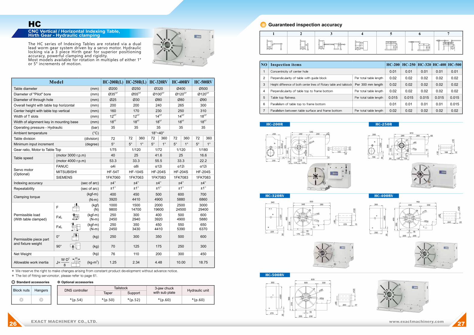
HC CNC Vertical / Horizontal Indexing Table,Hirth Gear - Hydraulic clamping
The HC series of Indexing Tables are rotated via a dual lead worm gear system driven by a servo motor. Hydraulic locking via a 3 piece Hirth gear for superior positioning accuracy, powerful clamping and rigidity.Most models available for rotation in multiples of either 1° or 5° increments of motion.
Model HC-200R(L) HC-250R(L) HC-320RV HC-400RV HC-500RVTable diameter (mm) Ø200 Ø250 Ø320 Ø400 Ø500Diameter of "Pilot" bore (mm) Ø35H7 Ø55H7 Ø100H7 Ø120H7 Ø120H7
Diameter of through hole (mm) Ø25 Ø30 Ø80 Ø80 Ø90Overall height with table top horizontal (mm) 200 200 240 265 300Center height with table top vertical (mm) 160 170 230 250 310Width of T slots (mm) 12H7 12H7 14H7 14H7 18H7
Width of alignment key in mounting base (mm) 18h7 18h7 18h7 18h7 18h7
Operating pressure - Hydraulic (bar) 35 35 35 35 35 Ambient temperature (°C) 18°~40°Table division (division) 72 72 360 72 360 72 360 72 360Minimum input increment (degree) 5° 5° 1° 5° 1° 5° 1° 5° 1°Gear ratio, Motor to Table Top 1/75 1/120 1/72 1/120 1/180
Table speed(motor 3000 r.p.m) 40 25 41.6 25 16.6(motor 4000 r.p.m) 53.3 33.3 55.5 33.3 22.2
Servo motor(Optional)
FANUC α4i α8i α12i α12i α12iMITSUBISHI HF-54T HF-104S HF-204S HF-204S HF-204SSIEMENS 1FK7060 1FK7063 1FK7083 1FK7083 1FK7083
Indexing accuracy (sec of arc) ±4’’ ±4’’ ±4’’ ±4’’ ±4’’Repeatability (sec of arc) ±1’’ ±1’’ ±1’’ ±1’’ ±1’’
Clamping torque (kgf-m) 400 450 500 600 700
(N-m) 3920 4410 4900 5880 6860
Permissible load(With table clamped)
F (kgf)(N)
10009800
150014700
200019600
250024500
300029400
FxL (kgf-m)(N-m)
2502450
3002940
4003920
5004900
6005880
FxL (kgf-m) (N-m)
2502450
3503430
4504410
5505390
6506370
Permissible piece partand fixture weight
0° (kg) 250 300 350 500 600
90° (kg) 70 125 175 250 300
Net Weight (kg) 76 110 200 300 450
Allowable work inertia W·D2
J= ¯¯¯¯ 8(kg-m2) 1.25 2.34 4.48 10.00 18.75
* We reserve the right to make changes arising from constant product development without advance notice.
* The list of fitting servomotor, please refer to page 61.
F
L
F
F
L
✽ Optional accessories
DNS controller Tailstock 3-jaw chuckwith sub plate Hydraulic unit
Taper Support
*(p.54) *(p.50) *(p.52) *(p.60) *(p.60)
◎ Standard accessories
Block nuts Hangers
◎ ◎
W
W
W
ØD
1 2 3 4 5 6 7
610265 60
12188
285200
20 130 13018
300
170
10
80
250
55
30
30190
100
345240
225
30
400
17018
170
230
320
225 15
80
100
170
140
200
25
190 18110 11010
160
305
240 240 60540
35
18182
Guaranteed inspection accuracy
NO Inspection items HC-200 HC-250 HC-320 HC-400 HC-500
1 Concentricity of center hole 0.01 0.01 0.01 0.01 0.01
2 Perpendicularity of table with guide block Per total table length 0.02 0.02 0.02 0.02 0.02
3 Height difference of both center lines of Rotary table and tailstock Per 300 mm length 0.02 0.02 0.02 0.02 0.02
4 Perpendicularity of table top to frame bottom Per total table length 0.02 0.02 0.02 0.02 0.02
5 Table top flatness Per total table length 0.015 0.015 0.015 0.015 0.015
6 Parallelism of table top to frame bottom 0.01 0.01 0.01 0.01 0.015
7 Parallelism between table surface and frame bottom Per total table length 0.02 0.02 0.02 0.02 0.02
265
250
35
455
250
205 205
430 330760
18
170
400
200
80
243 22
120
835330505
180
500
90
120
263 37
18
230255
310
560
270
30035
200

www.exactmachinery.com28 29EXACT MACHINERY CO., LTD.
HC-450H
HC-600H
HC-630H
HC-800H
HC-H CNC Horizontal Indexing Table withHirth Gear - Hydraulic Clamping
HC-H series Indexing Tables are rotated by a dual lead worm gear driven via a servo motor. Equipped with a 3 piece Hirth coupling, these tables achieve a superior positioning accuracy and the hydraulic clamping system provides the ultimate rigidity.High density housings resist flexing under load and can accommodate high machining forces.
Model HC-450H HC-600H HC-630H HC-800HTable dimension (LxW) (mm) 450 x 450 600 x 600 630 x 630 800 x 800Diameter of "Pilot" bore (mm) Ø50H7 Ø40H7 Ø40H7 Ø60H7
Overall height (mm) 280 320 320 380Width of T slots (mm) 18H7 20H7 20H7 22H7
Width of alignment key in mounting base (mm) 18h7 20h7 20h7 22h7
Operating pressure - Hydraulic (bar) 35 35 35 35 Ambient temperature (°C) 18°~40°Table division (division) 72 360 72 360 72 360 72 360Minimum input increment (degree) 5o 1o 5o 1o 5o 1o 5o 1o
Gear ratio, Motor to Table Top 1/120 1/180 1/180 1/180Rotation speed (motor 3000 r.p.m) 25 16.6 16.6 16.6
Servo motor(Optional)
FANUC α12i α12i α12i α22iMITSUBISHI HF-204S HF-204S HF-204S HF-354SSIEMENS 1FK7083 1FK7083 1FK7083 1FK7101
Indexing accuracy (sec of arc) ± 4” ± 4” ± 4” ± 4”Repeatability (sec of arc) ± 1” ± 1” ± 1” ± 1”
Clamping torque (kgf-m) (N-m)
6005880
8408232
8408232
126012348
Permissible load(With table clamped)
F (kgf)(N)
250024500
350034300
350034300
525051450
FxL (kgf-m)(N-m)
5004900
7006860
7006860
105010290
FxH (kgf-m) (N-m)
5505390
7707546
7707546
120011760
Permissible piece partand fixture weight 0° (kg) 1200 2500 2500 4000
Net Weight (kg) 400 650 720 1000
Allowable work inertia A2+B2
J= ¯¯¯¯ xW 12
(kg-m2) 40.5 150 150 426.6
* We reserve the right to make changes arising from constant product development without advance notice.
* The list of fitting servomotor, please refer to page 61.
Guaranteed inspection accuracyNO Inspection ltems HC-450H HC-600H HC-800H1 Concentricity of center hole 0.01 0.01 0.012 Table run out mm 0.01 0.015 0.0153 Table straightness mm 0.015 0.02 0.024 Parallelism between plate and base mm 0.015 0.02 0.025 Square of side reference plane mm 0.015 0.02 0.026 T-Slot tolerance mm 0.015 0.02 0.02
FL
W
H
F
F
PT 1/2
PT 1/2
Table unclamp
60
Table clamp
T-slots
160 16080
8478
204
10
805783
185
18
280
7
530
265
265
245
245
225
225
225 225450
200 200 105122 146
280
380
245
245
530
730
100 1008- 18
80
23
67117
40PT3/8
PT3/8
185
4x4-M10xP1.5
8080
18
30
31
12
100
380
226
117
7
100 100 100
146 27
204
8
100 100
400
100
100
150400 400
800
470
430
430
920
150 150 150
800
400
22
38
15
38
4x8-M12
30 4580
255
100
100
100
100
100
100
100
135Table unclamp
60
Table clamp
T-slots
350
22
W
A
B
100
20
50 85
5
125 20
9320
720
110
6
100 100 100
300
300
330
360
720
125300 300
600980
350380
60 330
330
72047
0
125 125 125
360
330
100
24-M1226PT1/2
PT1/2
100
80140
100
100
100
40
20
34
34
14
Table unclamp
Table clamp
T-slots
210
10-Ø22
315
315
345
345
375
750
125125 125 125315
630
375
315 350380
1010
6047
0
125125 125 125
107
201.
57
320
20 520
4
146
20125
125
125
27 80140
230
16-M16xP2.0
PT 1/2
PT 1/2
20
34
14 347884
27
Table unclamp
Table clamp
T-slots
10-Ø22
10-Ø22

EXACT MACHINERY CO., LTD.30 EXACT MACHINERY CO., LTD. www.exactmachinery.com 31
HC-HB Heavy Duty, CNC Horizontal Indexing Tablewith Hirth Gear - Hydraulic Clamping
HC-HB is suitable for horizontal machining center and boring / milling machine. Equipped with three piece hirth coupling gear to achieve super positioning accuracy.Particularly suitable for 180 degree double end boring.Table sizes from 1000mm to 2500mm or manufactured according to customer ’s requirement, loading capacity up to 20,000kgs (on request).
Model HC-1000HB HC-1400HB HC-1800HBWorking table dimension (LxW) (mm) 1000 x 1000 1400 x 1400 1800 x 1800Diameter of "Pilot" bore (mm) Ø60H7 Ø60H7 Ø100H7
Overall height (mm) 445 500 550Width of T slots (mm) 22H7 22H7 28H7
Operating pressure - Hydraulic (bar) 35 35 35 Ambient temperature (°C) 18o~40o
Table division (division) 72 360 72 360 72 360
Minimum input increment (degree) 5o 1o 5o 1o 5o 1o
Gear ratio, Motor to Table Top 1/360 1/720 1/720Table speed (motor 3000 r.p.m) 8.3 4.16 4.16
Servo motor (Optional)FANUC α22i α30i α30iSIEMENS 1FK7101 1FK7103 1FK7103HEIDENHAIN QSY155D QSY155F QSY155F
Indexing accuracy (sec of arc) ± 4” ± 4” ± 4”Repeatability (sec of arc) ± 1” ± 1” ± 1”
Clamping torque (kgf-m) (N-m)
170016660
240023520
320031360
Permissible load(With table clamped)
F (kgf)(N)
690067620
966094668
12600123480
FxL (kgf-m)(N-m)
140013720
196019208
260025480
FxH (kgf-m) (N-m)
160015680
230022540
300029400
Permissible piece partand fixture weight 0° (kg) 5000 8000 12000
Net Weight (kg) 3400 6000 8000
Allowable work inertia A2+B2
J= ¯¯¯¯ xW 12
(kg-m2) 833.3 2613.3 6480
* We reserve the right to make changes arising from constant product development without advance notice.
* The list of fitting servomotor, please refer to page 61.
Guaranteed inspection accuracyNO Inspection ltems HC-1000HB HC-1400HB HC-1800HB1 Concentricity of center hole 0.01 0.01 0.012 Table run out mm 0.02 0.02 0.033 Table straightness mm 0.02 0.03 0.044 Parallelism between plate and base mm 0.02 0.03 0.045 Square of side reference plane mm 0.02 0.03 0.046 T-Slot tolerance mm 0.02 0.02 0.02
FL
W
H
F
F
NCT-HB Heavy Duty, CNC Rotary Table
Guaranteed inspection accuracyNO Inspection ltems NCT-1000HB NCT-1400HB NCT-1800HB1 Concentricity of center hole 0.01 0.01 0.012 Table run out mm 0.02 0.02 0.033 Table straightness mm 0.02 0.03 0.044 Parallelism between plate and base mm 0.02 0.03 0.045 Square of side reference plane mm 0.02 0.03 0.046 T-Slot tolerance mm 0.02 0.02 0.02
Model NCT-1000HB NCT-1400HB NCT-1800HBWorking table dimension (LxW) (mm) 1000 x 1000 1400 x 1400 1800 x 1800
Diameter of "Pilot" bore (mm) Ø230H7 Ø330H7 Ø330H7
Overall height (mm) 445 500 550
Width of T slots (mm) 22H7 22H7 28H7
Operating pressure - Hydraulic (bar) 35 35 35
Ambient temperature (°C) 18o~40o
Minimum input increment (degree) 0.001o 0.001o 0.001o
Gear ratio, Motor to Table Top 1/360 1/720 1/720
Table speed (motor 3000 r.p.m) 8.3 4.16 4.16
Servo motor (Optional)
FANUC α22i α30i α30i
SIEMENS 1FK7101 1FK7103 1FK7103
HEIDENHAIN QSY155D QSY155F QSY155F
Indexing accuracy (sec of arc) 15” 15” 15”
Repeatability (sec of arc) 4” 4” 4”
Rotation torque (kgf-m) 600 750 900
(N-m) 5880 7350 8820
Permissible load(With table clamped)
F (kgf)(N)
400039200
500049000
600058800
FxL (kgf-m)(N-m)
7006860
10009800
200019600
FxH (kgf-m) (N-m)
180017640
250024500
350034300
Permissible piece partand fixture weight 0° (kg) 5000 8000 12000
Net Weight (kg) 3400 6000 8000
Allowable work inertia A2+B2
J= ¯¯¯¯ xW 12
(kg-m2) 833.3 2613.3 6480
* We reserve the right to make changes arising from constant product development without advance notice.
* The list of fitting servomotor, please refer to page 61.
FL
W
H
F
F
NCT-HB is suitable for horizontal machining center and boring/milling machine. Equipped with dual lead worm t ransmiss ion for min imum increment 0 .001 degree . Table sizes from 1000mm to 2500mm or manufactured according to customer ’s requirement, loading capacity up to 20,000kgs (on request).
W
A
B W
A
B

www.exactmachinery.com32 33EXACT MACHINERY CO., LTD.
CT SeriesNon-Lifting IndexingTable with HirthCoupling Gear
OUTSTANDING PERFORMANCE,RUGGED, RELIABLE WITH THEHIGHEST PRECISION
A CNC transfer machine of today is l ikely to be a flexible CNC
machine. It is especially suitable where different types of work pieces must
be produced in quantities. The machine is especially useful for industries
such as automotive, watches, livelihood necessities, and climate control
systems. CT series indexing tables are widely used in transfer machines
either as horizontal or vertical axis. Fast rotation time and high indexing
accuracy ensures outstanding productivity be produced in medium
to high quantities. Change livelihood to everyday necessities.
Application Examples
Function Principles of Non-Lifting Indexing Table
There are 3 gear rings to each Hirth CouplingGear ring A is attached to the rotating table top plate
Gear ring B is the "datum" attached to the table housing
Gear ring C raises and lowers inside the table housing to connect gear ring A and gear ring B together
after each cycle.
Please refer to drawing 2
● Gear ring C is shown lowered to release the locked assembly
● Gear ring A is now free to rotate with the table top
● After the rotation is complete, Gear A is now in the new location
● Gear ring C then raises to create a re-locked assembly as illustrated in drawing 1
Note: The raising and lowering of the gear rings is similar to a lapping effect.
The accuracy of the gear teeth improves over time.
BA
C
BA
C(unclamping / clamping route)
(up and down action gear)
Drawing 1 Drawing 2
CT-V
CT-ACT-TN
180° Shuttle Table for APC
CT-WS
CT series of Non-Lift ing Indexing Tables are used in Transfer
machines, dial machines or in any machines requiring repetitive
positioning with the accuracy and extreme rigidity only achievable
with a Hirth coupling and hydraulic clamping.
● Wide range of styles and sizes
● Robust and wear-resistant design
● High indexing accuracy and
repeatability values
● Resistance to high machining forces
● Simple installation with reliable operations
● Low maintenance design

www.exactmachinery.com34 35EXACT MACHINERY CO., LTD.
CT-200
CT-340
CT-470
CT Horizontal, Hydraulic Non-Lifting Indexing Table with Hirth Coupling Gear
The CT series of Indexing Tables are designed with a 3 piece Hirth coupling for high accuracy and repeatability without accumulat ive er ror. Tab le index ing i s v ia a hydraul ic rack & p in ion which prov ides h igh speed repetitive positioning with a smooth motion, the hydraulic clamping system ensures optimal clamping to withstand heavy cutting forces. The tables are offered with alternate Hi r th coup l i ng i n -o rde r to me e t va r i o us i ndex ing requirements to suit applications.
Model CT-200 CT-340 CT-470 CT-600 CT-800 CT-1000Table diameter (mm) Ø200 Ø340 Ø470 Ø600 Ø800 Ø1000Diameter of "Pilot" bore (mm) Ø30H7 Ø65H7 Ø90H7 Ø110H7 Ø120H7 Ø120H7
Depth of "Pilot" bore (mm) 30 11 12 11 40 50Diameter of through hole (mm) Ø27 Ø31 Ø41 Ø53 Ø80 Ø80Overall height (mm) 175 210 240 260 305 315Operating pressure - Hydraulic (bar) 35 35 35 35 35 35 Ambient temperature (℃ ) 18o~40o
Indexing divisions - Standard (division) 4,6,8,12 or 24Indexing divisions - Optional (division) 2,3,5 or 9Direction of rotation Clockwise and / or Counter ClockwiseIndexing accuracy (sec of arc) ± 4” ± 4” ± 4” ± 4” ± 4” ± 4”Repeatability (sec of arc) ± 1” ± 1” ± 1” ± 1” ± 1” ± 1”
Maximum mass moment of inertia
W·D2
J= ¯¯¯¯ 8(kg-m2) 7 21.25 45 125 300 420
Unclamp / Clamp Times (sec) 0.7 / 0.1 0.6 / 0.1 0.8 / 0.1 0.8 / 0.1 0.6 / 0.3 0.7 / 0.4"Typical" cycle time for 90° (sec) 1.3 2.3 2.5 3.8 3.9 4.0
Clamping torque (kgf-m) (N-m)
4003920
4804704
6005880
8408232
126012348
170016660
Permissible load(With table clamped)
F (kgf)(N)
10009800
160015680
250024500
350034300
525051450
690067620
FxL (kgf-m)(N-m)
2502450
3503430
5004900
7006860
105010290
140013720
FxH (kgf-m) (N-m)
2502450
4003920
5505390
7707546
120011760
160015680
Permissible weight ofpiece part & fixture 0° (kg) 250 500 700 1250 2400 3500
Net Weight (kg) 50 115 270 480 900 1350* The outlook dimension of 2 and 3 divisions will be different.
* "Typical" cycle time 90 degrees value base on 35kg/cm2, 2 HP, 30L/min regular hydraulic condition.
Guaranteed inspection accuracyNO Inspection ltems CT-200 CT-340 CT-470 CT-600 CT-800 CT-10001 Concentricity center hole mm 0.02 0.02 0.02 0.02 0.02 0.022 Table run out mm 0.02 0.02 0.02 0.02 0.02 0.023 Table straightness mm 0.02 0.02 0.02 0.02 0.02 0.024 Parallelism between plate and base mm 0.02 0.02 0.02 0.03 0.03 0.03
✽ Optional accessories
Rotary Joint Hydraulic unit Oil Pipe Special top plate
* * (p.60) * *
◎ Standard accessories
Hangers
◎
FL
W
H
F
F
W
ØD
4- 112- 10
2- 64
100
200
169 169
30
27
90
30 40
175
48.
5
42
175
110 110
180 180
360
145
145
175
135
41
150 72
20
6510
3
115
135
155
155
310
PT3/8"
PT3/8"
PT3/8"85 85 Table unclamp oil drain
oil fill
oil level
Switch signals
Table clamp
Prohibited working
CCW Cushion
Table-CW
PT3/8"Table-CCW
CW Cushion
Working depth 20
oil filloil level
Switch signals
Table clamp
CCW Cushion
Table-CW
CW Cushion Working depth 35
Table unclamp
Prohibited working
PT3/8PT3/8
PT3/8
6- 20
2- 15
30
220
47
0
10
0
34
12
1 90
41
550275275
255
190 190
600
155115
75
60
155
240
128
6015
018523
523
5
470
47019
065
30
255
Table-CCWPT3/8
67
127
169.
5
287 287
CW Cushion
CCW CushionWorking depth 30
Prohibited working
oil fill
Switch signals
oil level
Table-CW
Table clamp
Table unclamp
Table-CCW
400200 200
185 185
130
1030
160
160 160
460
160
170
170
340
4- 16
2- 15
160
30
34
0
65
31
11
100 83
25
340 130 130
217 217
59
.5
50
210
150
119.
5
61.5
PT3/8
PT3/8
PT3/8
PT3/8
EXACT MACHINERY CO., LTD.EXACT MACHINERY CO., LTD.3636 www.exactmachinery.com 37www.exactmachinery.com 37
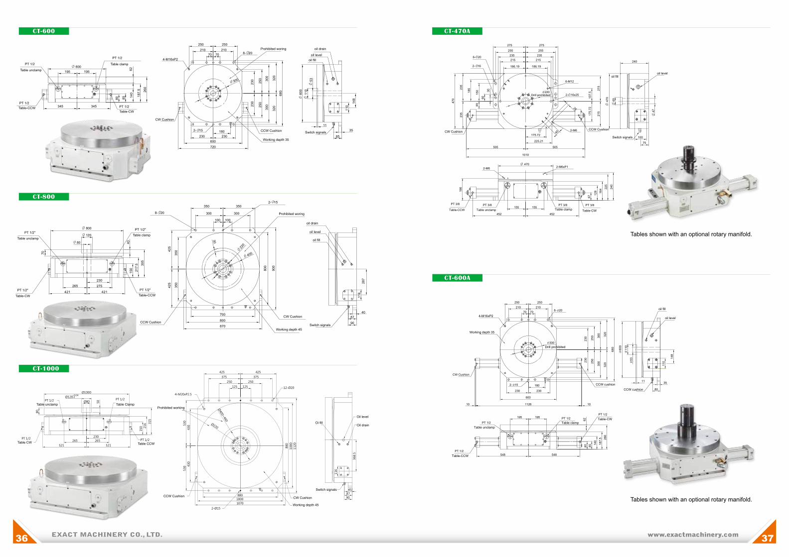
CT-600
CT-800
CT-1000
CT-470A
CT-600A
116
368.
5
458790
80
+0.04-0
230265265
PT 1/2
150 21
6 315
50
PT 1/2 PT 1/2
PT 1/2
125
250
375
425
125
250
375
425
430
430
530
530
8801000
880
1000
1120
4-M20xP2.5
Table clampTable unclamp
Table-CCW
CCW Cushion
Prohibited woring
oil drain
oil level
oil fill
Switch signals
CW Cushion
Working depth 45
Table-CW
Table Clamp
Table CW
Table unclamp
Table CCW
CCW Cushion CW Cushion
Switch signals
Oi fill
Oil level
Oil drain
Working depth 45
Prohibited working
Table clamp
Table unclamp
CW Cushion
Prohibited woring oil drain
oil leveloil fill
Switch signalsCCW Cushion
Working depth 35
Table-CCWTable-CW
35
230
521 521
1070
CCW cushion
CW Cushion
Table clampTable unclamp
Table-CW
Table-CCW
CCW cushion
4-M16xP2
PT 1/2PT 1/2
PT 1/2
PT 1/2
300
600
110
53
6280 85 14
0
187.
5 260
195 195
548548
2- 15
8- 20
180
230
230
230
250
250
11
110
148
600
1126
230
10
250210210
250
7070
Drill prohibited
Working depth 35
300
300
320
320
680
80
10
oil fill
oil level
CCW CushionCW Cushion
Table clampTable unclamp Table-CWTable-CCW
Switch signals
oil fill
6- 20
2- 16x25
2- 16
PT 3/8 PT 3/8
2-M6xP1
PT 3/8 PT 3/8
275
255 255235235
235
235
470
185
150
65
60
30
215 215
186.19
6-M12
2-M6
107.
517
5.72
215
215
186.19
275
25
40175.72
225.21
505
1010
505
470
4702-M6
47
100
65
155
190
155
452452
67
128 16
4 225
240
240
220Drill prohibited
75
35
oil level
Tables shown with an optional rotary manifold.
Tables shown with an optional rotary manifold.
421 421
870

www.exactmachinery.com38 39EXACT MACHINERY CO., LTD.
CT-200V
CT-250V
CT-320V
CT-V Vertical, Hydraulic Non-Lifting Indexing Table with Hirth Coupling Gear
Model CT-200V CT-250V CT-320VTable diameter (mm) Ø200 Ø250 Ø320Diameter of "Pilot" bore (mm) Ø30H7 Ø55H7 Ø65H7
Depth of "Pilot" bore (mm) 35 12 21Diameter of through hole (mm) Ø27 Ø30 Ø31Overall height of table assembly (mm) 290 370 395Center height of table axle (mm) 155 210 230Width of T slots (mm) 12H7 12H7 14H7
Width of alignment key in mounting base (mm) 18h7 18h7 18h7
Operating pressure - Hydraulic (bar) 35 35 35 Ambient temperature (°C) 18o~40o
Indexing divisions - Standard 4,6,8,12 or 24Indexing divisions - Optional 2,3,5 or 9Direction of rotation Clockwise and / or Counter ClockwiseIndexing accuracy (sec of arc) ± 4” ± 4” ± 4”Repeatability (sec of arc) ± 1” ± 1” ± 1”Maximum mass moment of inertia
W·D2
J= ¯¯¯¯ 8 (kg-m2) 7 10 21.25
Unclamp / Clamp Times (s) 0.7 / 0.1 0.7 / 0.1 0.6 / 0.1"Typical" cycle time for 90° (s) 1.3 2.0 2.3
Clamping torque (kgf-m) (N-m)
4003920
4504410
4804704
Permissible load(With table clamped)
F (kgf)(N)
10009800
150014700
160015680
FxL (kgf-m)(N-m)
2502450
3002940
3503430
FxL (kgf-m) (N-m)
2502450
3503430
4003920
Permissible weight ofpiece part and fixture 90° (kg) 95 130 200
Net Weight (kg) 50 110 170* The outlook dimension of 2 and 3 divisions will be different.* "Typical" cycle time 90 degrees value base on 35kg/cm2, 2 HP, 30L/min regular hydraulic condition.
Guaranteed inspection accuracyNO Inspection ltems CT-200V CT-250V CT-320V1 Plate straightness mm 0.015 0.015 0.0152 Table surface run outs mm 0.02 0.02 0.023 Parallelism between plate and base surface mm 0.02 0.02 0.024 Concentricity center hole mm 0.02 0.02 0.025 Square between plate and base surface mm 0.02 0.02 0.026 Square between plate and bottom anchor center line mm 0.02 0.02 0.027 Parallelism between plate, tailstock center line and base anchor mm 0.02 0.02 0.028 Tolerance between plate and tailstock center line mm 0.02 0.02 0.02
✽ Optional accessories
Tailstock 3-jaw chuckwith sub plate Hydraulic unit
Taper Support*(p.50) *(p.52) *(p.60) *(p.60)
◎ Standard accessories
Block nuts Hangers
◎ ◎
W
F
FL
L
F
The CT-V series of Indexing Tables are designed with a 3 piece Hirth coupling for high accuracy and repeatability without accumulat ive er ror. Tab le index ing i s v ia a hydraul ic rack & p in ion which prov ides h igh speed repetitive positioning with a smooth motion, the hydraulic clamp system ensures optimal clamping to withstand heavy cutting forces. The tables are offered with alternate Hirth couplings in-order to meet various index spacing to suit the application.
W
ØD
PT 3/8 PT 3/8
PT 3/8PT 3/8
110
150
4- 18
65
31
32
0
180
130
110 110
50
217 217
20
170210
220
45
370
165
230
395
35
3030
330460
18
200 200
440
514
23
9
23
Table-CCW
Table-CCW
Table-CCW Table-CW
Table-CW
Table-CW
Table-unclamp
Table-unclamp
Table-unclamp
T-Slots
T-Slots
T-Slots
Table-clamp
Table-clamp
Table-clamp
Switch signals
Switch signals
Switch signals
4- 14
360
210
290
2710
872
155
25518
100100230
12
8
21
20
330
180
135
150
45
200
15
135
165
25
82
58
173
263
PT 3/8
PT 3/8
PT 3/8
PT 3/8
65
167 167
65
30 27
35 145
PT 3/8 PT 3/8
PT 3/8
PT 3/8
55
250
100
155 3012 213
6- 18
215375
35
225 150215
50
25 25
175215
370
210
30
130
260
456
30
7
18
12
20
21
8
290125 125
21 199

www.exactmachinery.com40 41EXACT MACHINERY CO., LTD.
CT-WS-D CNC Non-Lifting Vertical / Horizontal Indexing Table,Built-in style - Hydraulic clamping with Hirth Gear
CT-WS-D Indexing Tables are rotated by a dual lead worm gear dr iven v ia a ser vo motor which provides rapid bi-directional indexing. An integrated hydraulically clamped 3 piece Hirth coupling ensures high indexing and repeatability accuracy, plus rigidity for heavy duty machining applications.
Model CT-250WS-D CT-350WS-D CT-450WS-D CT-600WS-DDiameter of table top (mm) Ø250 Ø265 Ø300 Ø380Diameter of mounting ring (mm) Ø340 Ø385 Ø450 Ø560Diameter of "Pilot" bore (mm) Ø55H7 Ø80H7 Ø100H7 Ø110H7
Depth of "Pilot" bore (mm) 12 15 35 40Diameter of through hole (mm) Ø30 Ø50 Ø50 Ø50Overall height (mm) 340 385 420 560Width of mounting keys (mm) 14h7 14h7 20h7 20h7
"Run-out" of pilot bore (mm) 0.02 0.02 0.02 0.02"Run-out" of table surface (mm) 0.02 0.02 0.02 0.02Operating pressure - Hydraulic (bar) 35 50 50 50Ambient temperature (°C) 18o~40o
Indexing divisions - Standard 4,6,8,12 or 24Indexing divisions - Optional 2,3,5 or 9Direction of rotation Clockwise and / or Counter ClockwiseIndexing accuracy (sec of arc) ± 4” ± 4” ± 4” ± 4”
Repeatability (sec of arc) ± 1” ± 1” ± 1” ± 1”
Gear ratio, Motor to Table Top 1/36 1/45 1/60 1/90
Table speed(motor 3000 r.p.m) 83.3 66.7 50 33.3(motor 4000 r.p.m) 111.1 88.9 66.7 44.4
Servo motor (Optional)
FANUC α8i α12i α12i α22iMITSUBISHI HF-154T HF-204S HF-204S HF-354SMITSUBISHI (General) HC-SF102 HC-SF202 HC-SF202 HC-SF352
Maximum mass mo-ment of inertia
W·D2
J= ¯¯¯¯ 8 (kg-m2) 15 18 25 65
Clamping torque(kgf-m)
(N-m)450
4410500
4900600
5880840
8232
Permissible load(With table clamped)
F (kgf)(N)
232022736
300029400
397038906
644863190
FxL (kgf-m)(N-m)
3002940
4003920
5004900
8408232
FxL (kgf-m) (N-m)
8358183
112511025
142813994
198019404
Permissible piece part andfixture weight
0° (kg) 350 500 700 1250
90° (kg) 160 280 280 500
Net Weight (kg) 100 200 220 350* We reserve the right to make changes arising from constant product development without advance notice.
* The list of fitting servomotor, please refer to page 61.
W
F
FL
W
F
L
W
ØD
Oil fillOil level
Table clamp Table unclamp
Zero return
Positionconfirm
Table clamp Pin
Table unclamp
8
52440
C20
52753.25
175.
47
PT 3/8PT 3/8 102.5102.5
160 16865.5
154.
42
180
29 20 2080
115
165 165
197327354
20+0 - 0
.013
+0.021+0
12-M12xP1.753-M16
+0.0
35- 0
+0 - 0.0
63
202-M12xP1.75P.C.D Ø425
2- Ø15H7 Pin 8- M12xP1.75P.C.D Ø270
8- Ø14 throughP.C.D Ø425
P.C.D Ø425 420
Ø450
20
420
Ø40
0h7
Ø39
6
Ø50
Ø30
0Ø
100h
720
h7
130 130 55
5 1235
503 54
193 108210
420
90200
294
8
321.5
Clamp confirme
Table Unclam Table Clam
Position Sensor
Oil Fill
Zero sensor
Oil level
PT 1/4 PT 1/4
157.
62
91 91Unclamp confirmed
CT-250WS-D
CT-600WS-D
CT-450WS-D
CT-350WS-D
PT 1/4Table Unclamp
Zero Sensor
PositionSensor
PT 1/4Table Clamp
323
20 140 148308
50 25 70488
130 213
Ø30
0h7
Ø25
0
80
97.3
2
14h7
51 2210
400
Table Clamp
Table Unclamp
310
310
155
155
20 20103 103
2-M10xP1.5P.C.D Ø320
8-M10xP1.5P.C.D Ø220
Ø340
Through
PT 1/4Table Unclamp
PT 1/4Table Clamp
PositionSensor
Zero Sensor
6 165 192.5
363.5
384.
84
2-M14xP2.0P.C.D Ø355
10-M12xP1.75P.C.D Ø195
20
118 118
2090 90
2-M5xP0.8
5
60 103 107 200.5
505.5
35
13
240
417.5
102.
5
127.
34
Ø38
5
Ø33
0h7
Ø26
5
14h7
Table Clamp
Table Unclamp

www.exactmachinery.com42 43EXACT MACHINERY CO., LTD.
Dimension
± 2 Sec Indexing Accuracy
MBT
Manual, Horizontal Indexing Table with Hirth Gear
Model MBT-450 MBT-600 MBT-800 MBT-1000 MBT-1200
Table dimension (mm) 450 x 450 600 x 600 800 x 800 1000 x 1000 1200 x 1200Diameter of "Pilot" bore (mm) Ø30H7 Ø40H7 Ø60H7 Ø60H7 Ø80H7
Overall height (mm) 170 200 280 300 340Width of T slots (mm) 18H7 20H7 22H7 22H7 22H7
Operating pressure (bar) Pneumatic 5~8Direction of rotation Bi-directional
Ambient temperature (oC) 18o~40o
Indexing divisions 72 360 72 360 72 360 72 360 72 360Indexing increments 5o 1o 5o 1o 5o 1o 5o 1o 5o 1o
Indexing accuracy (sec of arc) ± 2” ± 2” ± 2” ± 2” ± 2”
Repeatability (sec of arc) ± 1” ± 1” ± 1” ± 1” ± 1”
Clamping torque (kgf) 2200 3200 5400 6000 8100 (N) 21560 31360 52920 58800 79380
Permissibleload (with tableclamped)
F (kgf) (N)
240023520
340033320
450044100
600058800
700068600
FxL (kg) 4404312
6406272
108010584
120011760
162015876
FxH (kg) 4904802
7106958
120011760
133013034
180017640
Permissible piece part and fixture weight 0o (kg) 1000 2000 3000 5000 6000
Net Weight Net (kg) 200 400 1100 1350 2400
F
FL
HF
W
MBT series tables are designed with a 2 piece Hirth coupling for manually rotating in multiples of either 1° or 5° increments to an accuracy of +/- 2 seconds of arc. The tables are clamped pneumatically or hydraulically depending upon model, by a simple actuation lever or hand-held pendant. A vernier scale and pointer offers a reference during rotation, however, a digital scale is available on the larger tables (on request) These heavy duty, but simple and self contained tables are ideal for Jobs Shops or for applications where the indexing table needs to be frequently removed and re-installed to accommodate machine tool utility.
Guaranteed inspection accuracyNO Inspection ltems MBT-450 MBT-600 MBT-800 MBT-1000 MBT-1200
1 Concentricity of the center mm 0.01 0.01 0.01 0.01 0.012 Plate run out mm 0.01 0.015 0.015 0.02 0.023 Plate straightness mm 0.015 0.02 0.02 0.03 0.034 Parallelism between plate and base mm 0.015 0.02 0.02 0.03 0.035 Square of side reference plane mm 0.015 0.02 0.02 0.03 0.036 T-Slot tolerance mm 0.015 0.02 0.02 0.03 0.03
✽ Optional accessoriesSpecial top plate Different of standard T-slot Other
* * *
◎ Standard accessoriesBlock nuts Air purge
◎ ◎
Model MBT-450 MBT-600 MBT-800 MBT-1000 MBT-1200
A 450 600 800 1000 1200
B 170 200 280 300 340
C 100x4 100x5 100x7 125x7 200x5
DH7 30 40 60 60 80
EH7 18 20 22 22 22
F 30 34 38 38 38
G 12 14 15 15 15
H 30 34 38 38 38
A
C
DE
F
G
H
B
Maxx. T
ole
rance(u
m)
plate diameter (mm)
*Plain and customized table tops available upon request.
=2Sec.

EXACT MACHINERY CO., LTD.EXACT MACHINERY CO., LTD.44 www.exactmachinery.com 45
NCT-HPAuto-Pallet Changer and Rotary Table "Package"
Working table minimum input increment of 0.001°For Horizontal Machining Centers.The work table is rotated by a dual worm gear driven via a servo motor and clamped with hydraulic surrounding clamping system.Four high precision cone-shaped bushings ensure pallet repeatability accuracy. Two driving systems for APC available -- Driven by hydraulic rack & pinion or by servo motor with reduction gear box.
Model NCT-500HP NCT-630HP NCT-800HP
Pallet dimension (work table) (mm) 500 X 500 630 X 630 800 X 800
Diameter of "Pilot" hole in pallets (mm) Ø50H7 Ø50H7 Ø50H7
Height of Rotary Table (mm) 633 808 805
Width of T slots on pallets (mm) 14H7 18H7 18H7
Operation pressure - Hydraulic (bar) 35 35 35
Ambient temperature (oC) 18o~40o
Minimum input increment (degree) 0.001o 0.001o 0.001o
Gear ratio 1/180 1/180 1/180
Rotation speed (Rotary table) (motor 3000 r.p.m) 16.6 16.6 16.6
Servo motor (Optional)FANUC α12i α22i α22i
MITSUBISHI HF-204S HF-354S HF-354S
SIEMENS 1FK7083 1FK7101 1FK7101
Encoder (Optional) HEIDENHAIN RCN2390F(±5”) RCN2390F(±5”) RCN2390F(±5”)
Transmission Motor with reducer / Hydraulic rack & pinion
Maximum weight loading (kg) (single plate 600) 1200
(single plate 1200) 2400
(single plate 1600) 3200
Operation pressure for transmission - Hydraulic (bar) 50 50 50
Exchange times Motor & reducer (sec) 7.5 10 12.5
Rack & pinion (sec) 15 20 25
Indexing accuracy - mechanical (sec) 15” 15” 15”
Indexing accuracy - with Encoder (Option) (sec) ±5” ±5” ±5”
Repeatability (sec) ±2” ±2” ±2”
Clamping torque (kgf-m) (N-m)
200019600
260025480
340033320
Rotation torque (kgf-m) (N-m)
2402352
3002940
3903822
Permissible piece part weight 0o (kg) 600 1200 1600
Weight Net (kg) 2300 3000 4500
Allowable work inertia A2+B2
J= ¯¯¯¯ xW 12
(kg-m2) 25 80 170.6
W
W
A
B
HC-HPAuto-Pallet Changer and Indexing Table "Package"
Working table minimum input increment of 1° or 5°For Horizontal Machining Centers.The work table is equipped with dual lead worm and three piece hirth coupling gears with hydraulic clamping system to improve loading capacity. Four high precision cone-shaped bushings ensure pallet repeatability accuracy. Two driving systems for APC available -- Driven by hydraulic rack & pinion or by servo motor with reduction gear box.
Model HC-500HP HC-630HP HC-800HP
Pallet dimension (work table) (mm) 500 X 500 630 X 630 800 X 800
Diameter of "Pilot" hole in pallets (mm) Ø50H7 Ø50H7 Ø50H7
Height of Index Table (mm) 633 808 805
Width of T slots on pallets (mm) 14H7 18H7 18H7
Operation pressure - Hydraulic (bar) 35 35 35
Ambient temperature (oC) 18o~40o
Table division (division) 72 360 72 360 72 360
Minimum input increment (degree) 5o 1 o 5o 1 o 5o 1 o
Gear ratio 1/180 1/180 1/180
Rotation speed (Indexing table) (motor 3000 r.p.m) 16.6 16.6 16.6
Servo motor (Optional)FANUC α12i α22i α22i
MITSUBISHI HF-204S HF-354S HF-354S
SIEMENS 1FK7083 1FK7101 1FK7101
Transmission Motor with reducer / Hydraulic rack & pinion
Maximum weight loading (kg) (single plate 600)1200
(single plate 1200)2400
(single plate 1600)3200
Operation pressure for transmission - Hydraulic (bar) 50 50 50
Exchange timesMotor & reducer (sec) 7.5 10 12.5
Rack & pinion (sec) 15 20 25
Indexing accuracy - mechanical (sec) ±4” ±4” ±4”
Repeatability (sec) ±1” ±1” ±1”
Clamping torque (kgf-m) (N-m)
300029400
400039200
520050960
Permissible piece part weight 0o (kg) 600 1200 1600
Weight Net (kg) 2300 3000 4500
Allowable work inertia A2+B2
J= ¯¯¯¯ xW 12
(kg-m2) 25 80 170.6
W
W
A
B

EXACT MACHINERY CO., LTD.EXACT MACHINERY CO., LTD.46 www.exactmachinery.com 47
NCT-500HP&HC-500HP (Hydraulic rack and pinion)
NCT-630HP&HC-630HP (Hydraulic rack and pinion)
NCT-800HP&HC-800HP (Hydraulic rack and pinion)
NCT-500HP&HC-500HP (Motor & reducer)
NCT-630HP&HC-630HP (Motor & reducer)
NCT-800HP&HC-800HP (Motor & reducer)
626
740
447
894
808
315
630
840
315
630
315
630
315
630
1800
900 R1070
R400
R400
300 9070 80302010 605040330 340 0350310270 280 290 320
5001000
625
740
805
400
800
1000
400
800
400
800
400
800
1100
2200
R1300
R500
R500
500
250
500
250
583
336
444
250500
250
500
665
564
887358529
633
1330
R815
R335R335
0340 350300290280 330320310240 250 270260220210180 190 200 230
500
250
500
250
583
336
444
250500
250
500
1330665
564
887358529
633
R335R335
R815
0340 350300290280 330320310240 250 270260220210180 190 200 230
t
o j m
i
m
in n
t
oj
626
740
447
894
808
315
630
840
315
630
315
630
315
630
1800
900R400
R400
R1070
300 9070 80302010 605040330 340 0350310270 280 290 320
500
1000
625
740
805
400
800
1000
400
800
400
800
400
800
1100
2200
R1300
R500
R500

EXACT MACHINERY CO., LTD.48 EXACT MACHINERY CO., LTD. www.exactmachinery.com 49
HC-1250HP
HC-1250HPCNC Indexing Table with built-in Pallet Receiver, Hydraulic clamping with Hirth Gear
A heavy load capacity table designed for using on horizontal milling & boring machines. Table indexing via a servo motor for flexibility and rapid positioning. Indexing table is hydraulic clamping with Hirth coupling for accuracy and rigidity.
Model HC-1250HPPallet dimension (mm) 1250 X 1250Diameter of "Pilot" bore (mm) Ø55H7
Max. working diameter (mm) Ø1750Overall height of table (mm) 765Pallet transporter height (mm) Depends on height of B axisPallet transporter length (mm) 2062Width of T slots (mm) 22H7
Lifting stroke during pallet transfer (mm) 0.2~0.3Operation pressure (bar) 35 Ambient temperature (oC) 18o~40o
Table division (division) 72 360Minimum input increment (degree) 5o 1o
Gear ratio 1/360Rotation speed (Indexing table) (motor 3000 r.p.m) 8.3
Servo motor (Optional)FANUC α22iMITSUBISHI HF-354SSIEMENS 1FK7101
Hydraulic pressure (kg/cm2) 35Indexing accuracy (sec) ±4”
Repeatability (sec) ±1”
Clamping torque (kgf-m) (N-m)
500049000
Permissible piece part and fixture weight 0o (kg) 6000
Table weight Net (kg) 7500Transporter weight Net (kg) 6500
Allowable work inertia A2+B2
J= ¯¯¯¯ xW 12
(kg-m2) 1562.5
W
W
A
B
EDSNC Horizontal Rotary Table with Torque Motor Drive
High speed, Di rect Dr ive motor for rap id positioning and optimum agil ity. Hydraulic c lamp for maximum r ig id i ty dur ing stat ic machining operations.
型 式 EDS-320盤面直徑 (mm) Ø320盤面主軸中心孔 (mm) Ø90H7
盤面主軸中心孔深度 (mm) 25盤面主軸中心穿透孔 (mm) Ø45水平放置總高 (mm) 380垂直放置中心高 (mm) 210盤面 T 型槽寬 (mm) 14H7
基準導塊寬 (mm) 18H7
鎖緊裝置油壓使用壓力 (kg/cm2) 35適用環境溫度 (℃ ) 18°~40°等分割最小角度 (degree) 0.001°
伺服馬達
FANUC Dis 370 / 300電壓 (V) 200 400冷卻條件 液冷 無冷卻 液冷 無冷卻
最高迴轉速度 (min) 150 300
額定扭力
最大輸出(kgf-m) ( N-m)
37.8370
37.8370
連續輸出(kgf-m) ( N-m)
15.3 7.65 15.3 7.65150 75 150 75
譯碼器 HEIDENHAIN ECA4490F(±2.5")主軸中心孔旋轉偏擺 (mm) 0.01盤面旋轉起伏 (mm) 0.01
容許負荷( 鎖緊時 )
F (kgf)(N)
6506370
FxL (kgf-m)(N-m)
1401372
FxL (kgf-m)(N-m)
100980
容許積載荷重0º (kg) 400
90º (kg) 200
重 量 NET (kg) 305
F
FL
FL
W
W
EDS-320
395 18
816
2
185
185302
487
185 117
210
187
Ø32
030
380335
365
45
Ø45
Ø90
354 25

EXACT MACHINERY CO., LTD.50 EXACT MACHINERY CO., LTD. www.exactmachinery.com 51
MTS
MTS-B
ATS
ATS-B
MTS & MTS-B Manual Tailstock
T h e M T S a n d M T S - B t a i l s t o c k s a r e d e s i g n e d t o complement Non-lifting Indexing and NC Rotary tables when heavy and/or long work piece are machined. Quill travel is driven by handwheel.Standard center heights from 110~400mm, special sizes are available on request.
MTS & MTS-B Series / Manual Tailstock Table model #Model Center heights Overall heights Net weight TRT NCT HC CT-V
MTS-110 110 140 12 NCT-125
MTS-135 135 165 13 TRT-100NCT-170
HC-200NCT-200
MTS-155 155 185 14 CT-200VMTS-170 170 200 15 NCT-250 HC-250MTS-190 190 220 18 TRT-170
MTS-B-210 210 250 27 NCT-(B)-320 CT-250VMTS-B-230 230 270 30 TRT-250 HC-320 CT-320VMTS-B-250 250 290 33 NCT-(B)-400 HC-400MTS-B-255 255 295 34 TRT-320MTS-B-310 310 350 56 NCT-B-500 HC-500MTS-B-400 400 440 74 NCT-B-630
✽ MTS series quill taper MT#3. ✽ MTS-B series quill taper MT#4.
travel
travel
ATS & ATS-B Auto Tailstock
The ATS and ATS - B series tailstocks are available for either pneumatic or hydraulic operations. Standard center heights range is from 110 to 400mm. Optional center heights can be produced upon request .
ATS & ATS-B Series / Automatic Tailstock Table model # Model Center heights Overall heights Net weight TRT NCT HC CT-V
ATS-110 110 168 18 NCT-125
ATS-135 135 193 19 TRT-100NCT-170
HC-200NCT-200
ATS-155 155 213 20 CT-200VATS-170 170 228 21 NCT-250 HC-250ATS-190 190 248 25 TRT-170
ATS-B-210 210 267.5 34 NCT-(B)-320 CT-250VATS-B-230 230 287.5 37 TRT-250 HC-320 CT-320VATS-B-250 250 307.5 40 NCT-(B)-400 HC-400ATS-B-255 255 312.5 41 TRT-320ATS-B-310 310 367.5 63 NCT-B-500 HC-500ATS-B-400 400 457.5 81 NCT-B-630
✽ ATS series quill taper MT#3. ✽ ATS-B series quill taper MT#4.
travel
travel

www.exactmachinery.com52 53EXACT MACHINERY CO., LTD.
BTS
Accessories
M
L K
A
DGHGF
CE
B
I
B
J
BTSSupport Tailstock with Hydraulic Clamping
BTS Support Tailstock with Hydraulic Clamping Table model #
ModelCentral height B C D E F G K T Net
weight NCT HC CT-V
BTS-125 110 190 195 150 40H7 25 14h7 70 12H7 30 NCT-125
BTS-170135 221
170 125 30H7 25 14h7 94 12H727 NCT-170 HC-200
135 221 27 NCT-200155 241 33 CT-200V
BTS-200155 255
200 160 30H7 27 18h7 100 12H741 CT-200V
170 270 47 NCT-250 HC-250210 310 55 CT-250V
BTS-250170 300
260 150 50H7 32 18h7 120 12H779 NCT-250 HC-250
210 340 85 NCT-(B)-320 CT-250V230 360 90 HC-320 CT-320V
BTS-320210 390
320 195 50H7 32 18h7 150 14H7116 NCT-(B)-320
230 390 120 HC-320 CT-320V250 410 122 NCT-(B)-400 HC-400
BTS-400
250 455
410 230 60H7 51 18h7 140 14H7
238 NCT-(B)-400 HC-400310 515 258 NCT-B-500 HC-500400 605 290 NCT-B-630480 685 350 NCT-B-800
BTS-600400 705
610 240 75H7 65 18h7 200 18H7547 NCT-B-630
480 785 656 NCT-B-800650 955 1378 NCT-B-1000
BTS-800480 890
820 350 295H7 250 22h7 360 22H7787 NCT-B-800
650 1060 1653 NCT-B-1000750 1160 1985 NCT-B-1200
BTS-1000 650 1160 1020 380 305H7 260 22h7 410 22H7 1985 NCT-B-1000750 1260 2382 NCT-B-1200
✽ Most models are available with an integral Hirth coupling for an increased tangential load capacity.
The heavy duty BTS series of tailstocks are fitted with a free hydraulic brake assembly for maximum holding power. Used to support long and / or heavy piece parts or when fabricating a trunion style work holding fixture.Operating pressure = 35 bar
T-Slot
Model / Size A* B C D E F G H* I J K L* MNCT-125R+BTS-125 700 110 235 224 190 150 22 258 25 30 125 240 325
NCT-170R+BTS-170 800 135 275 245 220 125 22 392 30 35 170 250 350
NCT-200R+BTS-170 1000 135 273 246 220 125 22 587 40 40 200 250 355
NCT-250R+BTS-200 1120 170 300 256 270 160 22 662 40 40 250 290 420
NCT-320R+BTS-250 1200 210 385 328 340 150 25 710 50 50 320 340 410
✽ Details to suit the application.
BTS Tailstock
Base Plate Fixture Plate
Fixture platesupport bracket Table: Rotary or Indexing

www.exactmachinery.com54 55EXACT MACHINERY CO., LTD.
DNSAC Digital Single Axis NC Controller with MitsubishiGeneral Purpose Servo System
DNS series, self-contained single axis controllers are used in conjunction with Exact CNC Rotary and Rotary / Tilting Tables . Eas i ly programming from the f ront mounted keyboard, avai lable M-code connection to a machine contro l for an auto execut ion funtct ion . A por table electric handwheel is also available on request.
Model TRT NCT HC
DNS 106 TRT-100,TRT-170Rotary
NCT-125Tilting
DNS 110 TRT-250,TRT-320Rotary NCT-170,NCT-200,NCT-250
HC-200,HC-250Tilting NCT-250T,Multi-spindle series
DNS 120 TRT-450Rotary NCT-(B)-320,NCT-(B)-400,NCT-B-500
HC-320,HC-400,HC-500Tilting NCT-320T,NCT-400T
DNS 135 NCT-B-630,NCT-B-800,NCT-B-1000
Item Specification Item SpecificationDimensions 290 x 400 x 130mm ( Lx W x H ) Programmable angle 0.001o~360o
Input power 3 phase AC 220V ±10% 50 / 60 Hz Mini increment 0.001o
Servo motor AC servo with feedback Feeding rate F1~F2000Servo driver AC servo driver Program capacity 9 programs, 99 lines for each programZero return Available by software/ hardware Loop count Up to 999 times/ per step
Input system Key board Programmable pulse 1~±9999
Emergency stop Emergency button and Power switch
Dividing into equal parts 2 - 999 equal division
Parameter setting Available setting parameter M Code Connecting M/CProgram edit Front Key board PROG writing Weight 9.8kg
◎ Standard accessories
External cables with connector M-code connector
Main Power Motor power Motor feedback ◎
1.Main power switch
2.Program step display
3.Data display Position, speed and loop
4.Data enter keys Program edit
5.Mode button Program edit / data display normal → glisten
6.Function button Program edit / angle speed Loop
7.Program step browsingbutton
8.Emergency stop button(Pause)
9. Jog button
10. Zero return button
11. Start button
12. Clear button Program edit / clear error input
Operation / position clear to "0"
◎ Optional accessoriesPortable electric
handwheel*
POWER 3 AC220V
M CODE LINES FOR M/C
FEED BACK SIGNAL
CNC POWER LINES
BACKUP
TO ROTARY TABLE / INDEX TABLE
5
6
7
128
2 3
1
11 10 9
4
(-)
SQ3R(ZERO-RETURN)
0.5mm
WH No.10.5mm2
0.5mm2 WH No.6(+)
0.5mm2 WH No.7(-)
UNCLAMP
CLAMPWH No.4
WH No.5
0.5mm2
0.5mm2
SQ1R
1
4
5
67 7
6
701
541
45
1
SHIELD SHIELD NSHIELD
DETECTOR
CB
D
J4R
0.3mm20.3mm20.3mm20.3mm20.3mm2
0.5mm2 H
0.2mm20.2mm2
KL
0.5mm2 T
N
BC
AJ2R
MITSUBISHI SERVOMOTOR
M14 V
EW
UB
DC
AJ3R
YELLOW/GREEN
2mm2
2mm2
2mm2
2mm2
V
EW
UJ1R
B
DC
A
E
A
DE
F 0.3mm2
0.3mm0.3mm
0.3mm
GF
SRPJ
G
0.3mm2
0.3mm2
0.3mm2
0.3mm2
0.3mm2
0.3mm2
0.3mm2
SRPJ
A
CD
B
CN7
H
G
TLK
P
SR
N
J
FEDCBA
CN2
MRMRR
LG
BRAKE
LGP5E
24V
321
CN3
COMCLAMPUNCLAMP
DOG
BRAKE (24V)COM
910
2
8
6543
7
1
CN5 (OPTIONAL IN)
CN1
220V3 PHASES
RSTE
ABCD
PA
PB/PBPA/
PZPZ/
G
STEP0_COMCYCLE
START1_COMSTOP
6
10
8
7
9
345
12
CN4
MOTOR POWER
CNC ROTARY TABLE DNS INDIVIDUAL CONTROLLER
MS3102A20-29A
SRCN2A16-10S
SRCN2A16-10P
MS3102A20-4S
AUX
BLACK 1BLACK 2BLACK 3
DNS
POWER
Zero return direction
CW
J4R
J3R
J2R
I/O (OUT) IN
ENCODER MOTOR POWER AC LINE IN 220V
AUX1AUX
CN4 CN5 CN3
CN1CN7CN2
M CODE SIGNAL
NC DEVICE
J1R
M CODE
Power must be off during connecting or disconnecting.
GROUNDED

www.exactmachinery.com56 57EXACT MACHINERY CO., LTD.
Wiring DiagramDNS-AAC Digital NC Controller with Yaskawa Servo System
DNS-A ser ies , se l f-contained control lers are used in conjunction with Exact CNC Rotary and Rotary/Tilting Tables. Easily programming on the modern touch screen and editing by the same programming logic as machine CNC unit. A portable electric handwheel is available on request. DNS-A series is available to control 2 rotation axes on request.
Model TRT NCT HC
DNS 108A TRT-100, TRT-170 Rotary NCT-125Tilting
DNS 113ANCT-170, NCT-200
HC-200Multi-spindle series
DNS 118A TRT-250, TRT-320 Rotary NCT-250, NCT-250T HC-250Tilting
DNS 129A TRT-450Rotary NCT-(B)-320, NCT-(B)-400, NCT-B-500
HC-320, HC-400, HC-500Tilting NCT-320T, NCT-400T
DNS 144A NCT-B-630, NCT-B-800, NCT-B-1000 HC-630H, HC-800HDNS 155A NCT-B-1200 or special application
◎ Operation Panel
◎ Operation Mode
Machine Coordination Current axis coordination degree JOG Press JOG button and press A+ or A- to
execute jog rotation
Feed rate Current axis rotation speed (mm/min) HOME Under this module, press A+,A- to execute home position returned
G00 G00 Percentage setting (rapid feed) A+ Rotary/Indexing table Clockwise jogging.
G01 G01 Percentage setting (cutting feed) A- Rotary/Indexing table Counter-Clockwise jogging.
MPG Enable to operate Portable Electric Handwheel AUTO Execute automatic machining programs
Clamp Rotary/Indexing Table clamping MPG Simulation For trial processing.
Unclamp Rotary/Indexing Table unclamping Single Block G code execution is paused after one block is finished.
Item Description Specification Brand
SQ1 Proximity Switch E2E2-X3D1 NO OMRON
SQ2 Proximity Switch E2E2-X3D1 NO OMRON
SQ3 Proximity Switch E2E2-X3D2 NC OMRON
J1R MS Connector
MS3102A28-11P JAF
MS3108A28-11S JAF
J2R MS Connector
MS3102A20-29P JAF
MS3108A20-29S JAF
J3R MS Connector
MS3102A18-10P JAF
MS3108A18-10S JAF
J4R MS Connector
CM10-R10P-D JAF
CM10-SP10S-M JAF
POWER AC 220V MPG Brake Motor Power & I/O Motor encoder CNC connect
Zero return direction
CW
J4R
J3R
J2R J1R
clamp confirm
unclamp confirm
Home positionreturn
SQ1
SQ2
SQ3

30°
a Na
Nb
nMxP
d4
D1
d1
H1H3
H2
D2
W
dn
d2
d3
P.C
.D
K° 600 500 400 300 200 100 0(mm)
5.8 4.9 3.9 2.9 1.9 1.0400 300 200 100 50 0(mm)
7.8 5.8 3.9 1.9 1.0
EXACT MACHINERY CO., LTD.58 EXACT MACHINERY CO., LTD. www.exactmachinery.com 59
Hirth Coupling Gear2 Piece Hirth Couplings
Model N
o.
Teeth
Out D
iameter
Out D
iam
eter
In D
iam
eter
Teeth
Pro
file
Teeth
Thickn
ess
Teeth
Thickn
ess
Thickn
ess
Mounting screws Dowel pin holes Extractor screws Pitch
of to
p en
d
Num
ber
P.C
.D.
Diam
eter
Top D
iam
eter
Hole d
epth
Num
ber
P.C
.D.
Hole a
ngle
Diam
eter
Num
ber
P.C
.D.
Specifica
tion
of th
e teen
TN D1 D2 d1 W H1 H2 H3 Na P.C.D. d2 d3 dh Nb P.C.D. Ko d4 n P.C.D. MxP a24-12060 HV 24 120 118 60 8 18.30 14.0 34 6 80 6.6 11.0 6.0 1 80 30o 8 2 80 M8X1.25 1.340-14080 HV 40 140 138 80 12 18.37 14.0 34 6 100 6.6 11.0 6.0 3 100 30 o 8 2 100 M8X1.25 1.3724-180120 HV 24 180 178 120 10 21.61 16.5 40 8 140 9.0 14.0 8.0 3 140 22.5 o 8 2 140 M8X1.25 1.6124-200120 HV 24 200 198 120 10 21.63 16.5 40 8 150 9.0 14.0 8.0 3 150 22.5 o 8 2 150 M8X1.25 1.6372-200120 HV 72 200 198 120 10 20.99 16.5 40 8 150 9.0 14.0 8.0 3 150 22.5 o 8 2 150 M8X1.25 0.9924-250160 HV 24 250 248 160 11 21.42 16.5 40 8 195 11.0 17.5 10.0 3 195 22.5 o 10 2 195 M10X1.50 1.4272-250160 HV 72 250 248 160 12 21.42 16.5 40 8 195 11.0 17.5 10.0 3 195 22.5 o 10 2 195 M10X1.50 1.42360-250160 HV 360 250 248 160 7 20.30 16.5 40 8 195 11.0 17.5 10.0 3 195 22.5 o 10 2 195 M10X1.50 0.372-320210 HV 72 320 318 210 12 30.74 25.5 58 12 258 13.0 20.0 12.0 3 258 15 o 12 4 258 M12X1.75 1.74360-320210 HV 360 320 318 210 8 29.35 25.5 58 12 258 13.0 20.0 12.0 3 258 15 o 12 4 258 M12X1.75 0.8572-360250 HV 72 360 358 250 12 30.37 26.0 58 12 300 13.0 20.0 12.0 3 300 15 o 12 4 300 M12X1.75 1.37360-360250 HV 360 360 358 250 10 29.39 26.0 58 12 300 13.0 20.0 12.0 3 300 15 o 12 4 300 M12X1.75 0.3972-400280 HV 72 400 398 280 14 31.52 26.0 60 12 335 13.0 20.0 12.0 3 335 15 o 12 4 335 M12X1.75 1.52360-400280 HV 360 400 398 280 13 30.45 25.0 60 12 335 13.0 20.0 12.0 3 335 15 o 12 4 335 M12X1.75 0.4572-420320 HV 72 420 418 320 14 31.59 26.0 60 12 360 13.0 20.0 12.0 3 360 15 o 12 4 360 M12X1.75 1.59360-420320 HV 360 420 418 320 13 30.45 26.0 60 12 360 13.0 20.0 12.0 3 360 15 o 12 4 360 M12X1.75 0.4572-520415 HV 72 520 518 415 16 31.97 26.0 60 12 450 13.0 20.0 12.0 3 450 15 o 12 2 450 M12X1.75 1.97360-520415 HV 360 520 518 415 16 30.57 26.0 60 12 450 13.0 20.0 12.0 3 450 15 o 12 2 450 M12X1.75 0.5772-600480 HV 72 600 598 480 20 37.28 29.0 70 12 530 17.0 26.0 16.0 3 530 15 o 12 4 530 M12X1.75 2.28360-600480 HV 360 600 598 480 16 35.66 29.0 70 12 530 17.0 26.0 16.0 3 530 15 o 12 4 530 M12X1.75 0.6672-800660 HV 72 800 798 660 19 39.20 32.0 75 18 710 17.0 26.0 16.0 3 710 10 o 14 4 710 M12X1.75 1.70360-800660 HV 360 800 798 660 19 38.26 32.0 75 18 710 17.0 26.0 16.0 3 710 10 o 14 4 710 M12X1.75 1.9572-900740 HV 72 900 898 740 21 41.70 34.5 80 18 800 17.0 26.0 16.0 3 800 10 o 14 4 800 M12X1.75 2.20360-900740 HV 360 900 898 740 21 40.98 34.5 80 18 800 17.0 26.0 16.0 3 800 10 o 14 4 800 M12X1.75 0.98
Made of h igh qual i ty mater ia l s that ensure r ig id i ty and durabi l i ty. Precis ion hardened and ground for a guaranteed tooth spacing accuracy of +/- 2 seconds of arc. All pieces are interchangeable with each other.
*Custom sizes upon request
Max. tolerance (um)
plate radius (mm) =2Sec.
Hirth Coupling Gear 3 Piece Hrith Couplings
d1
d2
D1
H3 H3
H1
H2
H3
W
H4
d3
d4
dn
d3
d4
d5
d5
P.C
.DP
.C.D
NANa
NB
Nb
nMxP
MxPn
D2
30°
a
dn
B=A=
Model N
o.
Teeth
Teeth Profile
Out D
iameter
In Diam
eter
Out D
iameter
In Diam
eter
Teeth Thickness
Teeth Thickness
Thickness
Total Thickness
Pitch of top end
Mountingscrews
Dowel pinholes Extractor screws
P.C.D
.
Num
ber
Diam
eter
Top Diam
eter
Num
ber
Num
ber
Specificationof the teenNA
NaNBNb
ABTN W D1 d1 D2 d2 H1 H2 H3 H4 a
24-170069AB 24 17 - - 170 69 - 18 12 57 2.5 150
88 8 7 11 4 2 M6xP1
C 24 17 158 95 - - 43 - - 57 2.5 - 8 7 11 4 2 M6xP1
24-226100AB 24 16 - - 226 100 - 26 16 67 2 204
120 8 8 14 4 2 M8xP1.25
C 24 16 176 100 - - 45 - - 67 2 - 8 8 14 4 2 M8xP1.25
24-255115AB 24 20 - - 255 115 - 22 16 61 2 224
140 8 9 14 4 2 M8xP1.25
C 24 20 200 120 - - 43 - - 61 2 - 8 9 14 4 2 M8xP1.25
48-255115AB 48 20 - - 255 115 - 22 16 61 2 224
140 8 9 14 4 2 M8xP1.25
C 48 20 200 120 - - 43 - - 61 2 - 8 9 14 4 2 M8xP1.25
72-340160AB 72 24 - - 340 160 - 24.5 18 74 2 300
200 8 11 17.5 4 2 M10xP1.5
C 72 24 274 165 - - 53.5 - - 74 2 - 8 11 17.5 4 2 M10xP1.5
72-420230AB 72 22 - - 420 230 - 28 21 76 2 380
270 12 14 20 4 2 M12xP1.75
C 72 22 346 200 - - 45 - - 76 2 - 12 14 20 4 2 M12xP1.75
72-630390AB 72 31 - - 630 390 - 38 31 98 2 570
430 12 18 26 4 2 M16xP2
C 72 31 527 260 - - 65 - - 98 2 - 12 18 26 4 2 M16xP2
Made of h igh qual i ty mater ia ls that ensure r ig idi ty and durabi l i ty. Precis ion hardened and ground for a guaranteed tooth spacing accuracy of +/- 4 seconds of arc. All pieces are interchangeable with each other.
*Custom sizes upon request
Max. tolerance (um)
plate radius (mm) =4Sec.

60 EXACT MACHINERY CO., LTD.60 EXACT MACHINERY CO., LTD. www.exactmachinery.com 61www.exactmachinery.com 61
Accessories Accessories
Quick Change Chuck
Oil Manifold
Manual Chuck
PHC(Air over Oil intensifier)Pneumatic source 5~8 bar
Solenoid valve DC24V or
AC 110V/220V
Hydraulic unit1HP x 4P, 12 liter / min, 40L
2HP x 4P, 30 liter / min, 70L
Manual Chuck Suitable model
Model Size Sub Plate TRT NCT HC CT-VSC-5 5” ◎ NCT-125SK-6 6” ◎ TRT-170 NCT-170SK-7 7” ◎ NCT-200 HC-200 CT-200VSK-8 8” ◎ TRT-250 NCT-250 HC-250 CT-250V
SK-10 10” ◎ TRT-320 NCT-(B)-320 HC-320 CT-320V
SK-12 12” ◎ TRT-450 NCT-(B)-400NCT-B-500
HC-400HC-500
SK-16 16” ◎ TRT-450 NCT-(B)-400NCT-B-500
HC-400HC-500
SK-20 20” ◎ TRT-450NCT-(B)-400NCT-B-500NCT-B-630
HC-400HC-500
Manual Chuck
Quick-ChangeManual Chuck
Pneumatic Cylinder
Hydraulic Cylinder
Hydraulic Chuck
Pneumatic RotatingJoint
Pneumatic Quick Change Chuck
Pneumatic Chuck
Servo motor selection chart
Encoder-Heidenhain
Servomotor(FANUC, MITSUBISHI.....)
Indexing accuracy ±10” ±5” ±2.5” ±2” ±1”
Incremental
EncoderERN180
RON225RON275RON285
RON287 RON786 RON886
Absolute
Encoder
ECN223FECN225
RCN2380RCN2390FRCN5380
RCN5390F
RCN2580RCN2590FRCN5580
RCN5590F
RCN8380RCN8390F
RCN8580RCN8590F
※Other requirement, please contact us.
Motor axesFANUC Mitsubishi
Male connector Female connector Male connector Female connector
Power Cable Rotary axis MS3102A28-11P MS3108A28-11S MS3102A28-11P MS3108A28-11S
Tilting axis MS3102A28-11PZ MS3108A28-11SZ MS3102A28-11PZ MS3108A28-11SZ
Signal CableRotary axis MS3102A20-29PW MS3108A20-29SW MS3102A22-14P MS3108A22-14S
Tilting axis MS3102A20-29PZ MS3108A20-29SZ MS3102A22-14PZ MS3108A22-14SZ
Connector selection chart
FANUCα2 / 5000i α4 / 5000i α8 / 3000i α12 / 3000i α22 / 3000i α30 / 3000iα2 / 5000is α4 / 5000is α8 / 4000is α12 / 4000is α22 / 4000is α30 / 4000isβ4 / 4000is β8 / 3000is β12 / 3000is β22 / 3000is β30 / 2000is X
MITSUBISHIHG-105T HG-54T HG-104S HG-204S HG-354S HG-453SHF-105T HF-54T HF-104S HF-204S HF-354S HF-453S
HG-SR52J HG-SR102J HG-SR152J HG-SR202J HG-SR352J HG-SR502J
SIEMENS1FT6034 1FT6062 1FT6064 1FT6082 1FT6084 / 6102 1FT60861FK7042 1FK7060 1FK7063 1FK7083 1FK7101 / 7103 1FK7103
HEIDENHAIN QSY96G QSY116C QSY116J QSY155B QSY155D QSY155FFAGOR FKM22 FKM42 FKM44 FKM64 FKM66 X
YASKAWASGMJV-08ADA6S SGMGV-13ADA6S SGMGV-20ADA6S SGMGV-30ADA2S SGMGV-44ADA2S SGMGV-55ADA2SSGM7J-08A7C6S SGM7G-13A7C6S SGM7G-20A7C6S SGM7G-30A7C2S SGM7G-44A7C2S SGM7G-55A7C2S
※ If you have any other requirement, please contact us to get detail information.

62 EXACT MACHINERY CO., LTD. www.exactmachinery.com 63
Selection form of Rotary Table / Indexing Table
Machine Specification
Brand Model
Controller □ Fanuc □ Mitsubishi □ Siemens □ Heidenhain □ Fagor□ Other
Driver and cable for 4th
axisDriver prepared□ Yes □ No
□ Cable prepared(Electric cabinet to connector)
□ Software and PLC for 4th Axis
Dimension of woking table
Dimension :T - slot : Width mm * Pitch mm * Number
Rotary Table / Indexing Table
Model of Rotary Table :
Model of Indexing Table : Minimum input increment : □ 1° / □ 5°
Motor mounting position □ Right (R) □ Left (L) □ Back (RB)
Position of cable connection
□ Right □ Back □ Up □ Left
Left Top
Rear
L RightTop
Rear
R
Model of Servomotor (Optional)
Fanuc Mitsubishi Siemens Other_________
□ Straight Shaft □ Taper Shaft
□ Straight Shaft □ Taper Shaft
□ Straight Shaft □ Taper Shaft
□ Straight Shaft □ Taper Shaft
Model of Driver(Optional)
Fanuc Mitsubishi Siemens Other_________
Connector of Power and Signal Cable
□ Standard Connector (Japanese Standard)
□ Adherent connector (Euro Standard)
□ Direct connect without connector
Tailstock(Optional)
□ Manual Tailstock MTS □ Hydraulic Auto Tailstock ATS □ Pneumatic Auto Tailstock ATS
□ Support Tailstock with Hydraulic clamping BTS
□ Support Tailstock with Pneumatic clamping BTS
Power of PHC(Optional) □ AC220V □ AC110V □ DC24V
Hydraulic Unit(Optional)
□ 1HPx4P, 12L/min, 40L Single circuit solenoid valve for NCT only
□ 2HPx4P, 30L/min, 70LDouble circuit solenoid valvefor HC only
□ Other_________
Other accessories(Optional)
□ Chuck□ Pneumatic Chuck, Model:□ Manual Chuck, Model:□ Hydraulic Chuck, Model:
□ Oil manifold Specification: Input / Output
□ DNS Controller Power 220V/3PH Model:
Language of operation manual
□ Chinese □ English □ Other__________
Selection form of Tilting Rotary Table (5th AXIS)
Machine Specification
Brand Model
Controller □ Fanuc □ Mitsubishi □ Siemens □ Heidenhain □ Fagor□ Other
Drivers and cables for 4th / 5th axis
Driver prepared□ Yes □ No
□ Cables prepared (Electric cabinet to connectors)
□ Software and PLC for 4TH and 5th Axis
Dimension of woking table
Dimension :T - slot : Width mm * Pitch mm * Number :
Tilting Rotary Table □ TRT-100 □ TRT-170 □ TRT-200 □ TRT-250 □ TRT-320 □ TRT-450 □ TRT-TN □ ERT-250 □ ERT-350 □ ERT-500
Position □ Parallel with X Axis □ Parallel with Y Axis
Position of cable connection
□ Right □ Back □ Up □ Left
Model of Servomotor on Rotary Axis
(Optional)
Fanuc Mitsubishi Siemens Other_________
□ Straight Shaft □ Taper Shaft
□ Straight Shaft □ Taper Shaft
□ Straight Shaft □ Taper Shaft
□ Straight Shaft □ Taper Shaft
Model of Driver forRotary Axis(Optional)
Fanuc Mitsubishi Siemens Other_________
Model of Servomotor on Tilting Axis
(Optional)
Fanuc Mitsubishi Siemens Other_________
□ Straight Shaft □ Taper Shaft
□ Straight Shaft □ Taper Shaft
□ Straight Shaft □ Taper Shaft
□ Straight Shaft □ Taper Shaft
Model of Driver for Tilting Axis(Optional)
Fanuc Mitsubishi Siemens Other_________
Connector of Power and Signal Cable
□ Standard Connector (Japanese Standard)
□ Adherent connector (Euro Standard)
□ Direct connect without connector
Tailstock(Optional) □ Manual Tailstock MTS □ Hydraulic Auto Tailstock ATS □ Pneumatic Auto Tailstock
ATS
Power of PHC(Optional) 2 set Power : □ AC220V □ AC110V □ DC24V
Hydraulic Unit(Optional)
□ 1HPx4P, 12L/min, 40L Single circuit solenoid valve Other
Other accessories(Optional)
□ Chuck□ Pneumatic Manual Chuck, Model:□ Manual Chuck, Model:□ Hydraulic Chuck, Model:
□ DNS Controller Power 220V/3PH Model:
Language of operation manual □ Chinese □ English □ Other_________

64 EXACT MACHINERY CO., LTD. www.exactmachinery.com 65
TRT Series
TRT-100
0º~+90º 0º~+110º -20º~0º
Ø260Ø150
70
Ø130
20°
150 Ø150
TRT-170
0º~+90º 0º~+110º -30º~0º
Ø370
Ø210
80
Ø200
20°
175 Ø210
TRT-250
0º~+90º 0º~+110º -30º~0º
Ø440Ø410Ø300
100
130
Ø260
20°
190
Ø300
TRT-320
0º~+90º 0º~+110º -30º~0ºØ490Ø375Ø355
90
30
Ø320
20°
70
Ø355
TRT-450
0º~+90º 0º~+110º -30º~0ºØ650Ø530Ø500
125
65
Ø450
20°
100
Ø500
ERT Series
ERT-250
0º~+90º 0º~+110º -20º~0º
Ø450Ø410Ø300
100
130
Ø300
340
20°
Ø300
ERT-350
0º~+90º 0º~+110º -20º~0º
Ø520Ø405Ø385
90
30
Ø350
350
20°
Ø385
ERT-500
0º~+90º 0º~+110º -20º~0ºØ700Ø580Ø550
125
65
Ø550
400
20°
Ø550
Working Range
Calculation Instant Inertia Formula
Reference Data of Technological Information
D
D
J= x m8D2
J= x m8
D2+d2
D
d
d
D
J=( + ) x m12L2
16D2
D
L
J=( + ) x m12L2
16D2 + d2
D
L
d
J= x m12
A2 + B2
A
B
D
D
r
J= ( +r2 )x m8D2
D
d
d
Dr
J=( +r2 )x m8
D2+d2
J=( + +r2) x m12L2
16D2
r
D
L
D
L
d
r
J=( + +r2 )x m
12L2
16D2 +d2
J=( + r2 )x m
12A2 +B2
r
A
B
J=( + r2 )x m
12L2
L
r
J= x m12L2
L
Unit for Calculation
J = WR2 = kg‧m2
m = kg
A,B,D,L,d,r = m(meter)
Materials specification Gravity (S)
Cast Copper : 8.7
Steel Material : 7.8
Cast lron : 7.2
Aluminum : 2.7