Rotary Vapor Compression Cycle - Department of … Vapor Compression Cycle (RVCC) 2016 Building...
29
Rotary Vapor Compression Cycle (RVCC) 2016 Building Technologies Office Peer Review Arthur Kariya, Sandia National Laboratories [email protected] Scott Wujek, Creative Thermal Solutions [email protected]
-
Upload
hoangquynh -
Category
Documents
-
view
225 -
download
2
Transcript of Rotary Vapor Compression Cycle - Department of … Vapor Compression Cycle (RVCC) 2016 Building...
Rotary Vapor Compression Cycle (RVCC)2016 Building Technologies Office Peer Review
Arthur Kariya, Sandia National [email protected]
Scott Wujek, Creative Thermal [email protected]

2
Project Team
Arthur Kariya, PhD Wayne Staats, PhD Jeff Koplow, PhD
Scott Wujek, PhD Stefan Elbel, PhD Pega Hrnjak, PhD

3
Project Summary
Timeline:Start date: September, 2014Planned end date: February, 2017Key Milestones I. Characterize refrigerant flow patterns in rotating
frame (May 2016)II. Characterize air-side heat transfer enhancement
in the rotating frame (May 2016)III. Assess manufacturability of RVCC topology (Aug.
2016)
Budget:
Total Project $ to Date: • DOE: $774,000• Cost Share: $86,000
Total Project $ : • Same as above
Key Partners:
Creative Thermal Solutions
Urbana, IL
Project Outcome: This exploratory project will assess the viability of the RVCC concept, which can lead to substantial energy savings in the future. The following questions will be answered:
1. Can the air-side and refrigerant-side benefits in the rotating frame be harnessed for the expected operating conditions?
2. Can the RVCC topology be economically manufactured?

4
Purpose and Objectives
Problem Statement: The efficiencies of vapor compression cycles (VCCs) are currently limited by heat exchanger performance and compressor energy requirements
Target Market and Audience: Space heating and cooling comprises 31% of total energy consumption in the residential and commercial sectors (12 Quads)1,2. We propose a technology (RVCC) that can potentially reduce energy consumption by 21%.
Impact of Project:First step of development of a new rotating vapor compression cycle topology - Assessment of refrigerant flow and air-side
heat transfer in rotating frame- Assessment of economic manufacturability
Future Goal (4+ years):Development of 10 kW prototype for commercialization
Primary energy consumption in the residential
and commercial sectors2
1. http://www.eia.gov/oiaf/aeo/tablebrowser/2. BTO Multi-Year Program Plan

5
Approach
Approach: Our previous development of the rotating heat sink (Patent US8228675) has shown that heat transfer is enhanced in the rotating frame. Here, this approach is adapted to a larger scale for VCCs, where the evaporator and condenser are rotated.
Distinctive Characteristics: The entire vapor compression cycle is rotated
Key Issues:
1) The rotating heat evaporator and condenser must replace sizable stationary heat exchangers; the air-side heat transfer enhancement in the rotating frame must enable the down-sizing of the heat exchangers.
2) The refrigerant inside the evaporator and condenser is rotated. We expect additional refrigerant-side heat transfer enhancements to occur in the rotating frame; this must be investigated.
3) The new topology requires a different manufacturing method; the RVCC must be able to economically manufactured in volume

6
Inherent Inefficiencies in Vapor Compression Systems
Frosted evaporator in cold climates5
Broken connecting rod from liquid ingestion in compressor4
Progression of evaporator frosting6
Fouling of evaporator coil3
3. www.bakerhomeenergyconsultant.org 4. www.danfoss.com5. www.hvac-talk.com 6. www.appliance 411.com
7
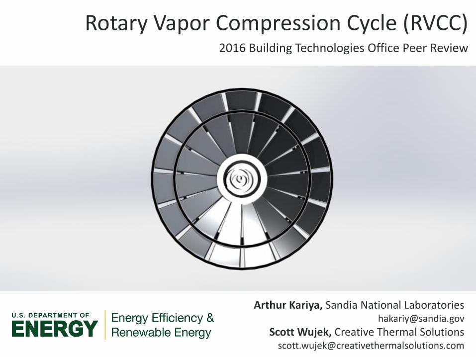
Rotary Vapor Compression Cycle (RVCC)
Conventional VCC
RVCC

8
Rotary Vapor Compression Cycle (RVCC)
RVCC
Method of reducing inefficiencies in vapor compression systemsSandia Rotating Heat Sink

9
Predicted Efficiency Improvements
Performance compared to 14.6 SEER heat pump
Cooling Heating
• Cooling mode: 21.3 % decrease in energy consumption– Elimination of superheat: 4%– Decreased condenser temperature: 10%– Increased evaporator temperature: 7%
• Heating mode: 9.8 % decrease in energy consumption– Elimination of superheating: 5%– Elimination of defrost cycle: 5%

10
Project Structure
CTS
Sandia
Characterize air-side heat transfer (Experimental)
Confirm sufficient convective heat transfer enhancement. Assess operating speeds when this heat transfer is achieved.
Characterize refrigerant flow(Experimental)
Confirm that centrifugal/Coriolisforces indeed separate the liquid/vapor phases. Confirm that refrigerant flow axisymmetric.
Sandia + CTS
Assess manufacturability
Confirm that resistance projection welding is a viable method of merging two clam-shell structures.
We must answer the following fundamental points for RVCC to be viable:1) Does the physics work out?
2) Can the RVCC topology be manufactured economically at scale?
Develop design for 1kW RVCC prototype

11
CHARACTERIZATION OF AIR-SIDE HEAT TRANSFER
GOAL:
• Characterize the heat transfer coefficient (HTC) on a rotating surface so that the required heat transfer area can be determined for RVCC application
Methodology
• Experimentally measure HTC for commercially available fan blades and standard shapes (i.e. cylinders, plates) as upper bound prediction
– Compare to HTC for non-rotating flat plate with similar airflow velocity to assess HTC enhancement in rotating frame
• Characterize HTC via transient cool-down tests
– Determine HTC scaling characteristics with radius and RPM
HTC = f (location on blade, RPM)

12
Air-side Convective Heat Transfer Laboratory Setup
Fan and camera
driven synchronously
with timing belts
Fan and camera
axially aligned
Robust chuck allows quick
replacement of fan blades
Infrared image
acquisition system
Infrared fan image

13
Co-rotating Infrared Imaging System
Flir Quark infrared camera Raspberry Pi 2
Battery
Triggers and saves IR
images
Transmits images via wifi
for subsequent analysis
Delivers power to
camera and computer
without slip rings
(2.0 Amps,10,000 mAh)
Small OEM core capable of
withstanding high g-forces
640x512 pixel video with a
temperature precision of 50 mK

14
Overall Fan Blade Temperature

15
Heat Transfer Coefficient
0 200 400 600 800 1000 1200 1400 1600 1800 20005
10
15
20
25
30
35
40
45
50
55
Time [s]
Tem
pera
ture
[°C
]
Method for determining convective heat transfer coefficient:
• Determine temperature at grid of points on fan blade
• Fit exponential decay function (determine time constant)
• Determine ratio of time constant to time constant with
known heat transfer coefficient
0
100
200
300
400
0
100
200
300
0
50
100
150
Position [mm]
Position [mm]
Convective h
eat
transfe
r coeff
icie
nt
[W/m
2-K
] 860 RPM, duct exhaust
Duct exhaust
Natural convection
Preliminary results show
rotating blade gives about
20% higher convective heat
transfer than would be
expected with a flat plate!

16
CHARACTERIZATION OF REFRIGERANT FLOW
GOALS:
1) Confirm axisymmetric refrigerant flow
2) Characterize liquid/vapor phase separation in the rotating frame
– Film/annular condensation
– Film/annular evaporation
Methodology
• Develop a system to visually study phase change and flow patterns in the rotating frame
– Having the complete refrigeration cycle in the rotating frame eliminates the need to channel fluids into/out of rotation
– Phase change behavior in channels will be viewed through transparent window
• Design a co-rotating camera system to film flow phenomena

17
Phase Change in the Rotating Frame
• Significant research has been directed at improving heat transfer in evaporating (condensing) channels flows– Problem 1: Access of liquid (vapor) to heat transfer area– Problem 2: Escape path of vapor (liquid) after phase change
• Potential improvements from centrifugal and Coriolis forces:1) Separation of phases due to density difference – allowing for easier
access to heat transfer area and escape path after phase change2) Rapid transport of fluid to heat transfer surface
7. http://www2.egr.uh.edu/~dli9/research.htm
Flow regimes in non-rotating two phase flow7

18
Refrigerant Visualization
Drive pulley
Compressor & housing (rotating)
CondenserEvaporator Evaporator
Transparent flow channels
Condenser
Evaporator
Transparent Cover
Mountingframe

19
Experimental Details
• Relevant experimental details: – Compressor: 1.9 cc/rev– Liquid refrigerant volume: 40-90 mL– System RPM: 0-600 RPM– Refrigerant: R134a– Camera resolution:
• 4k HD @ 30 FPS• 1080p @ 120 FPS
• Experimental goals:– Demonstrate VCC in rotation – Visualize liquid distribution in
evaporator and condenser (flooding)– Visualize symmetry of refrigerant flow– Analyze effect of throttle opening on
liquid distribution– Analyze the effect of refrigerant filling
volume– Analyze two-phase flow pathologies
High press.
Low press.
20
Progress and Accomplishments
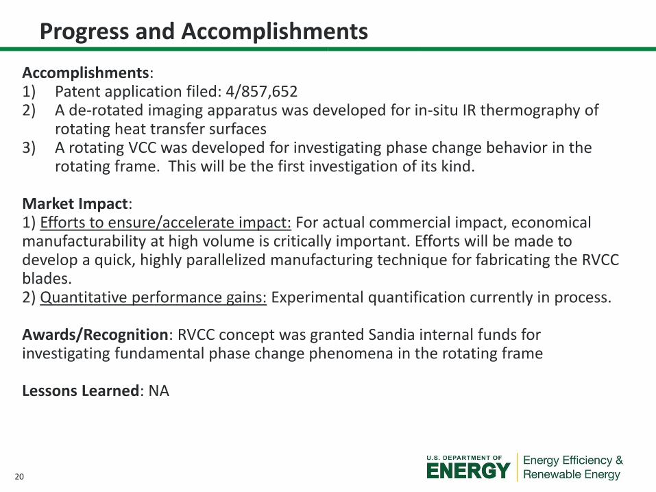
Accomplishments: 1) Patent application filed: 4/857,6522) A de-rotated imaging apparatus was developed for in-situ IR thermography of
rotating heat transfer surfaces3) A rotating VCC was developed for investigating phase change behavior in the
rotating frame. This will be the first investigation of its kind.
Market Impact: 1) Efforts to ensure/accelerate impact: For actual commercial impact, economical manufacturability at high volume is critically important. Efforts will be made to develop a quick, highly parallelized manufacturing technique for fabricating the RVCC blades.2) Quantitative performance gains: Experimental quantification currently in process.
Awards/Recognition: RVCC concept was granted Sandia internal funds for investigating fundamental phase change phenomena in the rotating frame
Lessons Learned: NA

21
Project Integration and Collaboration
Collaborators: Creative Thermal Solutions is taking the lead on the air-side heat transfer studies. They have experimental facilities that are perfectly suited for the project.
Project Integration: Sandia (technology inventor) has a multidisciplinary team with an extensive background in investigating heat transfer in rotating heat exchangers. CTS has expertise in heat transfer, VCCs and manufacturing. The two groups have weekly meetings to coordinate efforts and exchange information.
Communications: A part of the work will be presented at the International Refrigeration and Air Conditioning Conference (July, 2016)

22
Next Steps and Future Plans
Current BTO project and immediate follow-on (TRL 2 4)
• Confirm refrigerant/air flow benefits in rotating frame• Proof-of-concept stage• Build/test scaled-down
RVCC (1 kW)
Follow-on funding for design refinement and scaling up (TRL 45)
•Work with industry partner•Develop feedback throttling control•Further enhance refrigerant flow with internal structures and by altering surface wettability• Implement economical manufacturing scheme on actual heat exchangers•Build/test 10 kW RVCC
Transition/license technology to industry for commercialization
• Use 10 kW prototype to gather industry interest • Similar transition path
as used for the TRL 5 Sandia rotating heat sink
Year 1-3 Year 4-5 Year 6
Image: http://www.njcti.com
Rooftop ACs are limited in efficiencies due to weight restrictions. The lightweight RVCC can break that barrier.

23
REFERENCE SLIDES
24
Project Budget
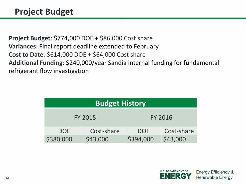
Project Budget: $774,000 DOE + $86,000 Cost shareVariances: Final report deadline extended to FebruaryCost to Date: $614,000 DOE + $64,000 Cost shareAdditional Funding: $240,000/year Sandia internal funding for fundamental refrigerant flow investigation
Budget History
FY 2015 FY 2016
DOE Cost-share DOE Cost-share$380,000 $43,000 $394,000 $43,000

25
Project Plan and Schedule
Project Schedule
Project Start: September 2014
Projected End: February 2017
TaskQ
1 (
Oct
-Dec
)
Q2
(Ja
n-M
ar)
Q3
(A
pr-
Jun
)
Q4
(Ju
l-Se
p)
Q1
(O
ct-D
ec)
Q2
(Ja
n-M
ar)
Q3
(A
pr-
Jun
)
Q4
(Ju
l-Se
p)
Q1
(O
ct-D
ec)
Q2
(Ja
n-M
ar)
Q3
(A
pr-
Jun
)
Q4
(Ju
l-Se
p)
Past Work
Milestone: Air-side heat transfer study
Milestone: Fabricate rotating imaging platform
Milestone: Design DAQ system
Milestone: Conduct refrigerant flow vizualization
Current/Future Work
Milestone: Manufacturing assessment / develop cost estimate
Milestone: Fabricate and assemble prototype test components
Milestone: Charge assembly with refrigerant
Milestone: Test evaporator in frosting conditions
Milestone: Write final report
Completed Work
Active Task (in progress work)
Milestone/Deliverable (Originally Planned)
Milestone/Deliverable (Actual)
FY2015 FY2016 FY2017
Project details• Initiation: Sept. 2014 (FY15); End: Feb. 2017
• Ending date (submission of final report) was moved to Feb. 2017 with program manager approval
• Final report will include design details of 1kW RVCC prototype, the development of which will be financially helped by
Sandia internal funding
• Initial delays encountered in developing rotating imaging (IR, visible light) facilities; with those facilities in place, future
experimental efforts expected to progress as scheduled
• Go/no-go decision points:
• Is there sufficient air-side heat transfer enhancements and refrigerant-side flow benefits in the rotating frame? (May 2016)
• Does the RVCC operate as expected? (Dec. 2016)
• Manufacturing assessment/cost estimate milestone was moved to later in the project in order to prioritize confirming the
fundamental physics underlying the RVCC concept

26
Details of Refrigerant Flow
Coriolis Phase Stratification
Vapor Flow(inward)
Liquid Flow(outward)
Throttle Orifices
Coriolis Separation
27
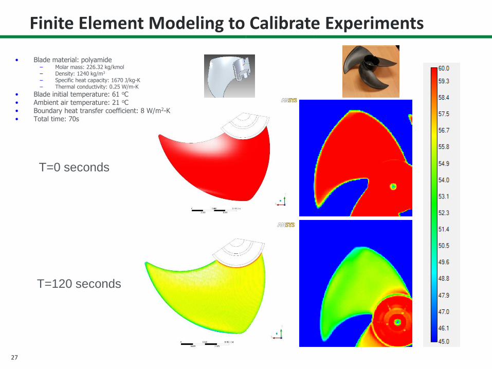
Finite Element Modeling to Calibrate Experiments
T=0 seconds
T=120 seconds
• Blade material: polyamide– Molar mass: 226.32 kg/kmol– Density: 1240 kg/m3
– Specific heat capacity: 1670 J/kg-K– Thermal conductivity: 0.25 W/m-K
• Blade initial temperature: 61 oC• Ambient air temperature: 21 oC• Boundary heat transfer coefficient: 8 W/m2-K• Total time: 70s

28
Manufacturing
Proposed fabrication:1) Cold forge parts2) Resistance projection weld the stack of forged parts

29
Single “layer” Single “shell” Close up view of knife-edged weld interfaces (blue)
Manufacturing


![Exergy Analysis of Vapor Compression Cycle...compression cycle, with flash intercooling with R22 using the exergy method and gave some useful conclusions. Dincer [17] asserts that](https://static.fdocuments.net/doc/165x107/5f36330828f5ef049b4d3cef/exergy-analysis-of-vapor-compression-cycle-compression-cycle-with-flash-intercooling.jpg)