Rotary shaft seals - M&M Intercom d.o.o.
19
Rotary shaft seals 5 Description of standard seal types 6 Additional types 7 Technical data 9 Installation and operation 10 Housing bore 12 Lubrication 13 Temperature 14 Pressure 15 Production and Quality assurance 16 Radiaseal ® 18 Splitring ® 20 Dina seals 21 C64D type 22 Storage and handling / Interchange table 23
Transcript of Rotary shaft seals - M&M Intercom d.o.o.

Rotary shaft seals
5
Description of standard seal types 6
Additional types 7
Technical data 9
Installation and operation 10
Housing bore 12
Lubrication 13
Temperature 14
Pressure 15
Production and Quality assurance 16
Radiaseal® 18
Splitring® 20
Dina seals 21
C64D type 22
Storage and handling / Interchange table 23

Rotary shaft seals
6
Description of standard shaft seal types (in accordance with DIN 3760)
Rubber covered O.D., metal insert, sealing lip with garter springA
Rubber covered O.D., metal insert, sealing lip with garter spring and additional dust lip
AS
B Outer metal case, sealing lip with garter spring
BS Outer metal case, sealing lip with garter spring and additional dust lip
C Outer metal case with reinforcing metal inner ring, sealing lip with garter spring
CS Outer metal case with reinforcing metal inner ring, sealing lip with garter spring and additional dust lip

Rotary shaft seals
7
Additional types
AS - P Reinforced sealing lip for overpressure, with or without additional dust lip
B - O Outer metal case, sealing lip without garter spring
C - O Outer metal case with reinforcing metal inner ring, without garter spring”
C - TE Inner metal case and sealing lip on O.D.; type B-TE available as well
C-DUO Outer metal case with reinforcing cap, twin sealing lips with two garter springs
COMBI SEALCombination of a shaft seal and an additional lip in polyurethane against soiling, all in one housing
Integrated sealing system: oil seal, wear sleeve and dust protection in one unit
RADIASEALRotary shaft seal with fabric reinforced outer diameter. See pag 18
SPLITRINGRotary shaft seal only rubber, split. See pag 20
DINA Seal Metal ODRotary shaft seal for needle bearing applications, without spring. See pag 21
DINA Seal Waved ODRotary shaft seal for needle bearing applications, without spring. See pag 21
C64D Rotary shaft seal for heavy industry. See pag 22
AS - PX Reinforced sealing lip and special metal insert for overpressure, with additional dust lip
A - DUO Twin sealing lips with two garter springs
A - O Sealing lip without garter spring
A - FL Different spring groove for a better spring retention, waved O.D.
A - LD Sealing lip with hydrodynamic ribs, left rotation
A - RD Sealing lip with hydrodynamic ribs, right rotation
A - WD Sealing lip with bi-directional hydrodynamic ribs
ASX7 Waved rubber cove-red O.D., metal insert, sealing lip with garter spring, with or without dust lip
A - EC End covers
Rubber covered I.D. and sealing lip on O.D.
A - TE
CASSETTE SEAL
Rotary shaft seals
8
Additional types
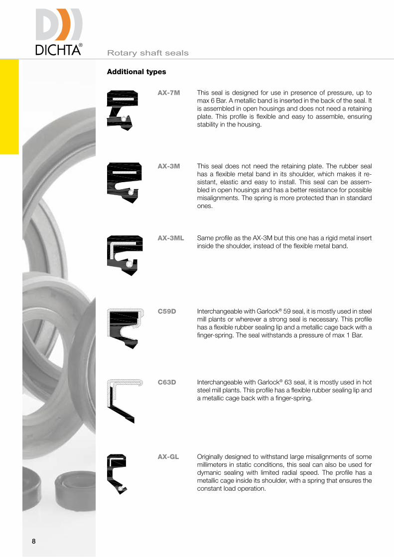
AX-7M This seal is designed for use in presence of pressure, up to max 6 Bar. A metallic band is inserted in the back of the seal. It is assembled in open housings and does not need a retaining plate. This profile is flexible and easy to assemble, ensuring stability in the housing.
AX-3M This seal does not need the retaining plate. The rubber seal has a flexible metal band in its shoulder, which makes it re-sistant, elastic and easy to install. This seal can be assem-bled in open housings and has a better resistance for possible misalignments. The spring is more protected than in standard ones.
AX-3ML Same profile as the AX-3M but this one has a rigid metal insert inside the shoulder, instead of the flexible metal band.
C59D Interchangeable with Garlock® 59 seal, it is mostly used in steel mill plants or wherever a strong seal is necessary. This profile has a flexible rubber sealing lip and a metallic cage back with a finger-spring. The seal withstands a pressure of max 1 Bar.
AX-GL Originally designed to withstand large misalignments of some millimeters in static conditions, this seal can also be used for dymanic sealing with limited radial speed. The profile has a metallic cage inside its shoulder, with a spring that ensures the constant load operation.
C63D Interchangeable with Garlock® 63 seal, it is mostly used in hot steel mill plants. This profile has a flexible rubber sealing lip and a metallic cage back with a finger-spring.

Rotary shaft seals
9
Technical data
Description of rotary shaft seal
Working principle
The area between the sealing edge and the shaft is the most important. The sealing effect is achieved by preloading the sealing lip, making its internal diameter slightly smaller than the shaft diameter. The garter spring ensures constant mechanical pressure and maintains the radial force to the shaft, flattening the sealing edge to defined width. Sealing is provided by the surface tension of the hydrodynamic oil film between the seal flattened area and the shaft. Oil thickness must be between 1 and 3 µm to avoid leakage. The meniscus acts as an interface between the outside air and the fluid. Any break in the meniscus will result in leakage. This can occur if the shaft contains scratches along the seal path.
Metal case
The metal insert or case is used to give strength and rigidity to the seal. Normally it is made of cold rolled steel in accordance with DIN 1624.To avoid rust or chemical attack, stainless steel can be used.Chrome Nickel AISI 304 (DIN 1.4301 - V2A)Chrome Nickel Molybdenum AISI 316 (DIN 1.4401 - V4A)
Garter spring
The garter spring maintains the radial force exerted by the sealing lip around the shaft surface. Normally produced in harmonic spring steel wire SAE 1074 (DIN 17223) or stainless steel wire Chrome Nickel AISI 302/304 (DIN 1.4300).For special applications also stainless steel springs in AISI 316 (DIN 1.4401 - V4a) are available. All our standard shaft seals produced in FPM compound are fitted with stainless steel springs in AISI 302/304.
rubber covered OD
metal insert
dust lip
sealing lip / back face sealing lip / front face
sealing edge
spring groove
garter spring
outside sealing surface
air-side
radial spring pressure
fluid-side
meniscus

Rotary shaft seals
10
Installation and operation
Shaft
The shaft surface finish is of primary importance for efficient sealing and for achieving a useful lifetime. Basically the hardness should increase with increasing peripheral speed. According to DIN 3760 minimum hardness required is 45 HRC. At a peripheral speed of 4 m/s the hardness should be 55 HRC and at 10 m/s 60 HRC. Recommended hardness depth: 0.3 mm if shafts are not fully hardened.
Lubrication is also very important. Surface finish as specified by DIN 3760 must be Ra 0.2 to 0.8 μm, Rz 1 to 5 μm, with RMAX = 6.3 μm. Rougher surfaces generate higher friction, hence higher temperatures. Machining defects and scratches on the shaft must be avoided.
Even very small defects could be sufficient to increase the film thickness, eventually rupturing the meniscus and causing leakage. It is also important to avoid spiral grinding or marks, because they can cause a pumping effect and leakage.
Recommended machining tolerance is ISO h11 according to DIN 3760 (see table below).
Shaft diameter (mm) Tolerance
from
6
10
18
30
50
80
120
180
250
315
to
10
18
30
50
80
120
180
250
315
400
h11
0- 0,090
0- 0,110
0- 0,130
0- 0,160
0- 0,190
0- 0,220
0- 0,250
0- 0,290
0- 0,320
0- 0,360

Shaft eccentricity
Shaft diameter (mm)
Perm
issi
ble
eccen
tric
ity
(mm
)
Shaft run out
Shaft speed (RPM)
Shaft
run o
ut
(mm
)
Rotary shaft seals
11
Installation and operation
The best working condition is to have a shaft rotating perfectly centered and concentric to the axis of the rotary shaft seal. Obviously this is not possible and inevitably some shaft run out is always present. Therefore the sealing lip must compensate for it. The higher the rotation speed is, the smaller can be the permissible shaft run out which can be compensated by the sealing lip, because the inertia of the sealing lip prevents it from following the shaft movements. It is therefore advisable to install the seal immediately adjacent to the bearing and minimize bearing play.
Eccentricity between shaft and housing bore centers must be avoided as much as possible so as to reduce unilateral load (wear) of the sealing lip.

Rotary shaft seals
12
Housing bore
A good press fit of the shaft seal onto the housing bore is vital. The result is a stable installation.
Recommended machining tolerances of the housing bore diameter for rotary shaft seals are H8 according to DIN 3760 (see table below).
The maximum surface roughness of the housing according to DIN 3760 is: Ra 1.6 to 6.3 μm, Rz 10 to 20 μm, with RMAX = 25 μm.We recommend the use of a shoulder or a spacer ring against which the seal can be located. Should this not be possible one has to pay special attention that the seal is installed perpendicularly to the shaft axis.To ease installation the entrance of the groove should have a chamfer inclined by 10° - 20° and a depth according to the ring thickness (see figure below). Also the mounting end of the shaft should have a chamfer inclined by 15° - 30°, with rounded and polished edge.
ToleranceHousing bore (mm)
from
10
18
30
50
80
to
18
30
50
80
120
h8
+ 0,027 0
+ 0,033 0
+ 0,039 0
+ 0,046 0
+ 0,054 0
ToleranceHousing bore (mm)
from
120
180
250
315
400
to
180
250
315
400
500
h8
+ 0,063 0
+ 0,072 0
+ 0,084 0
+ 0,089 0
+ 0,097 0
D H
8
15° ÷ 30°
5° ÷ 10°
1 ÷ 1.5 mm

Rotary shaft seals
13
Lubrication
Lubrication is very important for good functioning and lifetime of the seal. The sealing lip does not actually run on the shaft directly, but on an oil film, called meniscus. The thickness of the meniscus is usually between 1 - 3 μm, but is influenced by many factors such as oil viscosity, shaft surface finish and seal radial load.
The first few hours of operation is called the «bedding-in» time. This is necessary not only for the meniscus to form, but also for the sealing edge to flatten. During this time limited leakage is possible.
Adequate lubrication strongly reduces friction between sealing lip and shaft and also acts as a coolant to the generated heat. The lower the temperature can be kept, the longer will be the life expectancy of the seal. Should the fluid have poor lubricating capability (water and aqueous solutions), dust lip-type (AS, BS or CS) rotary lip seals must be used. In such a case make sure to fill the space between the two lips with grease. The friction heat also depends on the peripheral speed of the shaft.
Friction not only can be detrimental to the lip material, but also can cause a power loss which could be quite significant if low power is transmitted.
Sealing lip frictional heat
Shaft diameter in mm
exc
ess
tem
pera
ture
°C
Frictional power loss
Peripheral Speed m/s
Watt

Rotary shaft seals
14
Temperature
The temperature on the sealing lip is the medium temperature increased by the temperature caused by frictional heat.The higher the effective operating temperature is, the faster the ageing of the elastomer will be, thus affecting the performance of the sealing lip and the shaft.Frictional heat depends on seal design and material, peripheral speed, sealing lip preloading spring force, shaft design and surface finish, lubrication, medium, etc.
Permissible speeds in pressure-free state to DIN 3760
Shaft diameter
rpm
Perm
ess
ible
speed

Rotary shaft seals
15
Pressure
In most applications there is no or little differential pressure. Where the rotary shaft seal is exposed to pressure, however, the sealing lip is pressed against the shaft, thus increasing temperature. In some cases the pressure can even cause overturning of the sealing lip.
Over 0,2 bar at higher peripheral speeds or over 0,5 bar at low peripheral speeds back up rings or special designed rotary shaft seals with stronger sealing lip and supporting metal insert must be used. For the latter we refer to our P-types (e.g. AS-P). Nevertheless permissible overpressures with P-type shaft seals are limited (see diagram below).
On request we can supply shaft seals with special reinforced lip to withstand pressure over the indicated value.
If back up rings are installed standard rotary shaft seals can be used. However, back up rings increase costs and often the necessary space for installation is not available. Sometimes the use of back up rings is even not possible, since it requires a very accurate fitting as well as very low eccentricity of the shaft.
Specially designed rotary shaft seals (P-types) are therefore preferred, even if more accurate fitting and lower eccentricity of the shaft than in normal cases is required.
Rotary shaft seals AS-P. Permissible Overpressure

Rotary shaft seals
16
Production and Quality assurance
Our rotary shaft seals are manufactured according to German Standards DIN 3760 and Quality Assurance Standards ISO 9001.
All production phases are checked and all measurements are recorded and stored for traceability.
In accordance with German Standards DIN 3760
1) The average value for d2 taken from a number of measurements shall not be greater than the value specified for d2 plus the interference allowance.
2) The tolerance on d2 (i.e. d2max - d2min) is to be determined by taking three or more measurements equally spaced around the circumference.
Interference allowance and permissible eccentricity
Seal outer diameter d2
(mm)
Interference allowance (1)
Types A, AS Types B, BS, C, CS
Tolerance on d2 (2)
Types A, AS, B, BS, C, CS
up to 50
over 50 to 80
over 80 to 120
over 120 to 180
over 180 to 300
over 300 to 500
0,25
0,35
0,50
0,65
0,80
1,00
+0,30 +0,20+0,15 +0,10
+0,35 +0,23+0,20 +0,13
+0,35 +0,25+0,20 +0,15
+0,45 +0,28+0,25 +0,18
+0,45 +0,30+0,25 +0,20
+0,55 +0,35+0,30 +0,23
A AS B BS C CS

Rotary shaft seals
17
Production and Quality assurance
Final inspection standard
In accordance with our Production standards and DIN 3761 Part 4.
The contact band width of the sealing lip is defined, according to DIN 3761 part 4, as follows:
Shaft diameter(mm)
Front band width(mm)
Back band width(mm)
up to 50
50 to 120
over 120
1,2
1,5
2
0,5
0,8
1
Zone Not permitted Permitted
Contact band
1 = Front side
2 = Back side
Well of seal
Seal O.D.
Chamfer
Spring retention lip
Inside wall
1+2
3
4
5
6
7
Breaks in Sealing Edge
Bond failures
Fault which will affect
the sealing on O.D.
Faults which will affect
the installation of the seal
Shortcomings could
cause break
Free burrs
No fault permitted
Minor faults provided that
at least 2/3 of the O.D. is
unbroken at this point
Small shortages
Burrs permitted if bonded
or secured to the inside wall
4
5
7
3
6
12
4
5
3
6
12
7
Rotary shaft seals
18
Types for special applications
Radiaseal®
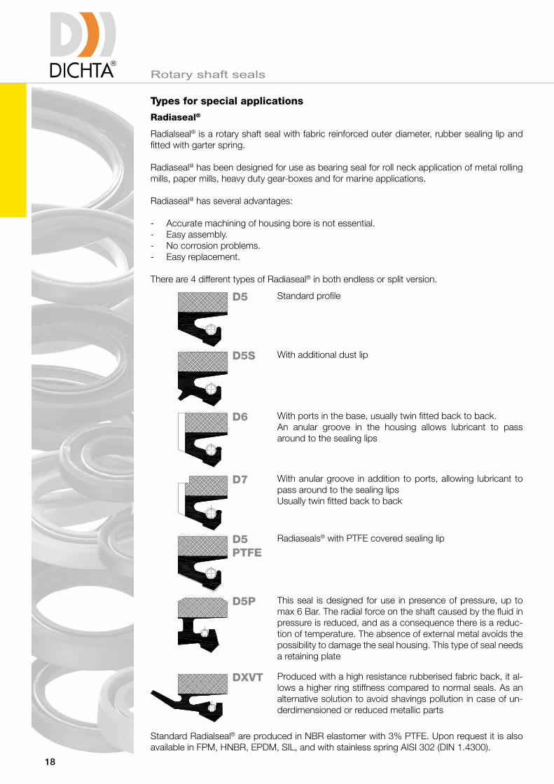
Radialseal® is a rotary shaft seal with fabric reinforced outer diameter, rubber sealing lip and fitted with garter spring.
Radiaseal@ has been designed for use as bearing seal for roll neck application of metal rolling mills, paper mills, heavy duty gear-boxes and for marine applications.
Radiaseal@ has several advantages:
- Accurate machining of housing bore is not essential.- Easy assembly.- No corrosion problems.- Easy replacement.
There are 4 different types of Radiaseal® in both endless or split version.
Standard Radialseal® are produced in NBR elastomer with 3% PTFE. Upon request it is also available in FPM, HNBR, EPDM, SIL, and with stainless spring AISI 302 (DIN 1.4300).
D5 Standard profile
D5S With additional dust lip
D6 With ports in the base, usually twin fitted back to back. An anular groove in the housing allows lubricant to pass around to the sealing lips
D7 With anular groove in addition to ports, allowing lubricant to pass around to the sealing lipsUsually twin fitted back to back
D5 PTFE
Radiaseals® with PTFE covered sealing lip
D5P This seal is designed for use in presence of pressure, up to max 6 Bar. The radial force on the shaft caused by the fluid in pressure is reduced, and as a consequence there is a reduc-tion of temperature. The absence of external metal avoids the possibility to damage the seal housing. This type of seal needs a retaining plate
DXVT Produced with a high resistance rubberised fabric back, it al-lows a higher ring stiffness compared to normal seals. As an alternative solution to avoid shavings pollution in case of un-derdimensioned or reduced metallic parts
L
D H
8
d h
9
H
Rotary shaft seals
19
Types for special applications
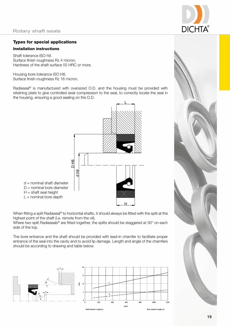
Shaft tolerance ISO h9.Surface finish roughness Rz 4 micron.Hardness of the shaft surface 55 HRC or more.
Housing bore tolerance ISO H8.Surface finish roughness Rz 16 micron.
Radiaseal® is manufactured with oversized O.D. and the housing must be provided with retaining plate to give controlled axial compression to the seal, to correctly locate the seal in the housing, ensuring a good sealing on the O.D.
When fitting a split Radiaseal® to horizontal shafts, it should always be fitted with the split at the highest point of the shaft (i.e. remote from the oil).Where two split Radiaseals® are fitted together, the splits should be staggered at 30° on each side of the top.
The bore entrance and the shaft should be provided with lead-in chamfer to facilitate proper entrance of the seal into the cavity and to avoid lip damage. Length and angle of the chamfers should be according to drawing and table below.
d = nominal shaft diameterD = nominal bore diameterH = shaft seal heightL = nominal bore depth
Installation instructions30°
15°
a
b
Dd
B
L
Rotary shaft seals
20
Types for special applications
Splitring®
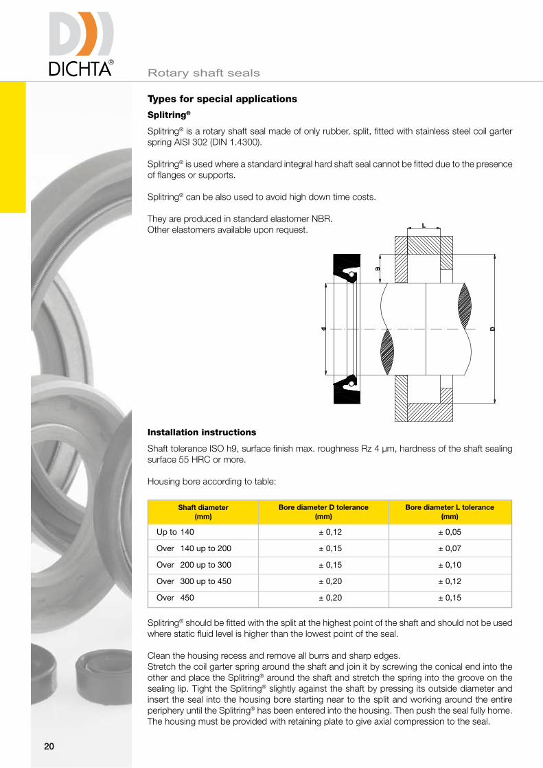
Splitring® is a rotary shaft seal made of only rubber, split, fitted with stainless steel coil garter spring AISI 302 (DIN 1.4300).
Splitring® is used where a standard integral hard shaft seal cannot be fitted due to the presence of flanges or supports.
Splitring® can be also used to avoid high down time costs.
They are produced in standard elastomer NBR.Other elastomers available upon request.
Installation instructions
Shaft tolerance ISO h9, surface finish max. roughness Rz 4 µm, hardness of the shaft sealing surface 55 HRC or more.
Housing bore according to table:
Splitring® should be fitted with the split at the highest point of the shaft and should not be used where static fluid level is higher than the lowest point of the seal.
Clean the housing recess and remove all burrs and sharp edges. Stretch the coil garter spring around the shaft and join it by screwing the conical end into the other and place the Splitring® around the shaft and stretch the spring into the groove on the sealing lip. Tight the Splitring® slightly against the shaft by pressing its outside diameter and insert the seal into the housing bore starting near to the split and working around the entire periphery until the Splitring® has been entered into the housing. Then push the seal fully home. The housing must be provided with retaining plate to give axial compression to the seal.
Shaft diameter(mm)
Bore diameter D tolerance(mm)
Bore diameter L tolerance(mm)
Up to 140
Over 140 up to 200
Over 200 up to 300
Over 300 up to 450
Over 450
± 0,05
± 0,07
± 0,10
± 0,12
± 0,15
± 0,12
± 0,15
± 0,15
± 0,20
± 0,20
Rotary shaft seals
21
Types for special applications
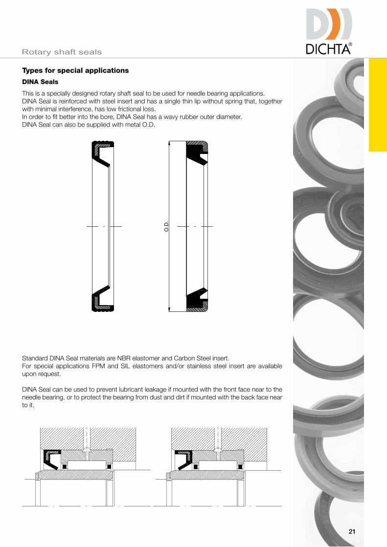
DINA Seals
This is a specially designed rotary shaft seal to be used for needle bearing applications.DINA Seal is reinforced with steel insert and has a single thin lip without spring that, together with minimal interference, has low frictional loss.In order to fit better into the bore, DINA Seal has a wavy rubber outer diameter. DINA Seal can also be supplied with metal O.D.
Standard DINA Seal materials are NBR elastomer and Carbon Steel insert.For special applications FPM and SIL elastomers and/or stainless steel insert are available upon request.
DINA Seal can be used to prevent lubricant leakage if mounted with the front face near to the needle bearing, or to protect the bearing from dust and dirt if mounted with the back face near to it.
O.D
.

Rotary shaft seals
22
Types for special applications
C64D Seals Seal construction
This seal is interchangeable with Garlock® 64 seal.
C64D shaft seal has been developed specifically for severe operating conditions in heavy industry. The performance and life of the seal in these conditions, involving important axial tolerances (shaft tolerances, shaft run out, non eccentricity and bearings clearance), are largely dependant upon the preload of the seal lip on the shaft.
C64D shaft seal has a very flexible sealing lip with a finger spring/garter spring combination that compensates shaft deviations without the need of changing the lip preload.
1. Garter spring Material: AISI 302 To provide a regulated loading on
the sealing lip and enable the sealing element to follow shaft deflections.
2. Sealing lip Compound: FPM, NBR, SIL
3. Stainless steel spring carrier Material: ACX 260 AISI 316L 2D Designed to ensure the spring
retention during the assembly. If necessary to permit the removal and refitting of garter spring to provide a predetermined sealing lip preload which will permit the sealing element to follow shaft deflections.
4. Steel filler ring Material: Fe 37 To provide the rigidity required and to
ensure an accurate assembly of the seal in the groove.
5. Steel outer ring Material: Fe-P04
FPM SIL NBR
-20 / +120
75
≤ 25
-60 / +120
70
≤ 25
-20 / +220
75
≤ 35
Temperature [°C]
hardness [°ShA]
Max operating speed [m/s]

Rotary shaft seals
23
Storage and handling
Some storage precautions must be taken in order to avoid deterioration of the material. Rotary shaft seals should be stored in a dust free and dry atmosphere and they must be kept in their original wrapping which should only be opened just before installation. Samples sholud be repacked after inspection. Excessive humidity will deteriorate some elastomers as well as cause corrosive damage to metal casing and spring.Do not drop rotary shaft seals on shelves or boxes, nor hang seals on hooks, wires or nails,since in either case the sealing lip can be damaged. Seals should be stored in a horizontal position.Seals should be used on a first-in first-out basis to avoid ageing on the shelf. Avoid storage near sources of heat or near electrical equipments that may generate ozone. Also keep away from direct sunlight.
Shaft seals interchange table
Dichta types A AS AS-P A-O A-DUO B BS C CS
BA
827N
DG
A
CB
A
R21
IE
hMS4
35
SC
WA
G
BASL
827S
DGS
ASL
CC
FA
R23
IEL
hMSA7
32
TC
WAS
GP
BABSL
827SK
DGSP
CF
TCN
WASY
GAP
BAOF
827NO
DE
AOF
CD
SA
R26
IO
VC
WAO
GSM
BADUO
827D
DGD
ADUO
CK
DUPLEX
R22
IELR
DC
WAD
G2
B1
822N
DF
B
BB
ABI
R4
EE
CRW1
48
SB
WB
L1
B1SL
822S
DFS
BSL
BC
R6
EEL
CRWA1
47
TB
WBS
L1P
B2
824N
DFK
C
DB
R1
EEP
CRWh1
45
SA
WC
L2
B2SL
824S
DFSK
CSL
DC
CRWhA1
41
TA
WCS
L2P
Simrit-Freudenberg
Goetze
Kako
Simmerwerke
Stefa
Gaco
Pioneer Weston
Paulstra
Chicago Rawhide
National
NOK
Dichtomatik
FP