Rotary Jet Mixer Iso-Mix 15 · 2016-04-23 · General Description Instruction Manual, Rotary Jet...
55
Instruction Manual Rotary Jet Mixer IM 15 IM-TE91I150-EN5 ESE02184EN Date of issue: February 4, 2015 First published: September 2009 Covering ƒ Standard Machines ƒ Machines delivered with ATEX Certification in accordance with Directive 94/9/EC Original manual
Transcript of Rotary Jet Mixer Iso-Mix 15 · 2016-04-23 · General Description Instruction Manual, Rotary Jet...
Instruction Manual
Rotary Jet Mixer IM 15
IM-TE91I150-EN5ESE02184EN
Date of issue: February 4, 2015 First published: September 2009
Covering Standard Machines Machines delivered with ATEX Certification in accordance with Directive 94/9/EC
Original manual


Contents
Instruction Manual, Rotary Jet Mixer Iso-Mix 15 Page 1Standard machines and machines delivered with ATEX certificationin accordance with Directive 94/9/ECIM-TE91I150-EN5
Contents
Contents ................................................................................................................................... 1 Introduction ............................................................................................................................... 3 Intended Use ............................................................................................................................ 3 Patents and trademarks............................................................................................................ 3 ATEX Marking ........................................................................................................................... 4 General Description .................................................................................................................. 5
Functionality......................................................................................................................................... 5 Standard Configurations for IM 15 Rotary Jet Mixer ............................................................................ 9 Available add-ons ................................................................................................................................ 9
Technical Data........................................................................................................................ 10 Rotary Jet Mixer Iso-Mix 15 with 2 nozzles........................................................................................ 10 Rotary Jet Mixer Iso-Mix 15 with 4 nozzles........................................................................................ 11 Flow rate ............................................................................................................................................ 12 Throw length ...................................................................................................................................... 13 Time for complete cleaning pattern (8 cycles) ................................................................................... 14
Installation and Normal Operation .......................................................................................... 15 General Safety and Installation Instructions....................................................................................... 15 Method for tightening the nozzles ...................................................................................................... 16 Normal Operation .............................................................................................................................. 17 Special Conditions for Safe Use in accordance with the ATEX Certification, Directive 94/9/EC........ 19
Service and Repair of ATEX Approved Machines.................................................................. 21 Maintenance and Repair ........................................................................................................ 22
Preventive Maintenance .................................................................................................................... 22 Top Assembly .................................................................................................................................... 24 Bottom Assembly............................................................................................................................... 26 Hub Subassembly.............................................................................................................................. 28 Stem Subassembly............................................................................................................................ 30 Gear Subassembly ............................................................................................................................ 32 Replacement of Collar Bushes .......................................................................................................... 34 Replacement of Ball Races................................................................................................................ 36 Replacement of Main Collars............................................................................................................. 38
Tools ....................................................................................................................................... 40 Standard Tool kit for IM 15 Rotary Jet Mixer, Article No. TE81B055 ................................................. 40 Sketch of Tools for replacement of Collar bush ................................................................................. 40 Sketch of Tools for replacement of Main collars ................................................................................ 41
Trouble Shooting Guide.......................................................................................................... 42 Symptom: Slow rotation or failure of machine to rotate ..................................................................... 42
IM 15 Rotary Jet Mixer with 4 nozzles.................................................................................... 44 Reference List of Parts ...................................................................................................................... 44 Cross Sectional Drawing.................................................................................................................... 45
IM 15 Rotary Jet Mixer with 2 nozzles.................................................................................... 46 Reference List of Parts ...................................................................................................................... 46 Cross Sectional Drawing.................................................................................................................... 47

Contents
Service intervals ..................................................................................................................... 48 Standard Spare Part Service Kits and Tool Kits..................................................................... 48
Standard Spare Part Service Kit for IM 15 Rotary Jet Mixer, Article No. TE31B299.......................... 48 Standard Tool Kit for IM 15 Rotary Jet Mixer, Article No. TE81B055 .................................... 48
Special Tools for IM 15 Rotary Jet Mixer ........................................................................................... 48 General Information ................................................................................................................ 49
How to Order Spare Parts.................................................................................................................. 49 Service and Repair ............................................................................................................................ 49 How to contact Alfa Laval Tank Equipment ....................................................................................... 49
Declaration of Conformity ....................................................................................................... 50
© Alfa Laval Corporate ABThis document and its contents is owned by Alfa Laval Corporate AB and protected by laws governing intellectual property and thereto related rights. It is the responsibility of the user of this document to comply with all applicable intellectual property laws. Without limiting any rights related to this document, no part of this document may be copied, reproduced or transmitted in any form or by any means (electronic, mechanical, photocopying, recording, or otherwise), or for any purpose, without the expressed permission of Alfa Laval Corporate AB. Alfa Laval Corporate AB will enforce its rights related to this document to the fullest extent of the law, including the seeking of criminal prosecution.

Contents
Instruction Manual, Rotary Jet Mixer Iso-Mix 15 Page 3Standard machines and machines delivered with ATEX certificationin accordance with Directive 94/9/ECIM-TE91I150-EN5

Introduction
Instruction Manual, Rotary Jet Mixer Iso-Mix 15 Page 3Standard machines and machines delivered with ATEX certificationin accordance with Directive 94/9/ECIM-TE91I150-EN5
Introduction
This manual has been prepared as a guide for the persons who will be operating and maintaining your Alfa Laval Rotary Jet Mixer Iso-Mix 15. The key to long life for your mixer will always be a system of carefully planned maintenance; you will appreciate that a mixer which has a rough and dirty job to do will need more frequent attention than one working in ideal conditions.
Note: Get the best and most economical performance from your Alfa Laval Rotary Jet Mixer Iso-Mix 15.Insufficient preventive maintenance means poor performance, unscheduled stops, shorter lifetime and extra costs. Good preventive maintenance on the contrary means good performance, no unscheduled stops and superior total economy.
You will find the information contained in this manual simple to follow, but should you require further assistance, our technical department will be pleased to help you. Please quote the type and serial number with all your enquiries; this will help us to help you. The type and serial number are placed on the gear house of the mixer.
Note: The illustrations and specifications contained in this manual were effective at the date of printing. However, as continuous improvements are our policy, we reserve the right to alter or modify any unit specification on any product without prior notice or any obligation.
Intended Use
It is to be verified by the end-user:
- that the machine is in conformity with respect to tank, vessel or container size in which it will be used. - that the construction materials (both metallic and non-metallic) are compatibility with product, flushing
media, cleaning media, temperatures and pressure under the intended use.
Patents and trademarks
This Instruction Manual is published by Alfa Laval Kolding A/S without any warranty. Improvements and changes to this Instruction Manual may at any time be made by Alfa Laval Kolding A/S without prior notice. Such changes will, however, be incorporated in new editions of this Instruction Manual.
© Alfa Laval Kolding A/S. All rights reserved.
Alfa Laval Rotary Jet Mixer Iso-Mix 15 product has patents in the EPO member states and in other countries.The Alfa Laval logotype is a trademark or a registered trademark of Alfa Laval Corporate AB. Other products or company names mentioned herein may be the trademarks of their respective owners. Any rights not expressly granted herein are reserved.

ATEX Marking
Page 4 Instruction Manual, Rotary Jet Mixer Iso-Mix 15Standard machines and machines delivered with ATEX certification
in accordance with Directive 94/9/ECIM-TE91I150-EN5
If ordered with ATEX certificate:
ATEX Marking
The Rotary Jet Mixer Iso-Mix 15 is certified as category I component. The certification is carried out by the certified body Baseefa, who has issued the certificate no. 10ATEX0188X. The marking on the ATEX certified Rotary Jet Mixer Iso-Mix 15 is as follows:
Serial number explanation
Machines supplied with or without normal documentation:yyyy-xxxxx: serial numberyyyy: yearxxxxx: 5 digit sequential number
Changes to the machine are not allowed without approval by the person responsible for the ATEX certification at Alfa Laval Tank Equipment. If changes are made – or spare parts other than Alfa Laval original spare parts are used - the EC Type Examination certification (the ATEX Directive) is no longer valid.
Important ATEX information:
Also see page 19 regarding special conditions for repair of ATEX certified machines.

General Description
Instruction Manual, Rotary Jet Mixer Iso-Mix 15 Page 5Standard machines and machines delivered with ATEX certificationin accordance with Directive 94/9/ECIM-TE91I150-EN5
General Description
The Rotary Jet Mixer Iso-Mix 15 is a media driven and media lubricated tank/reactor mixer. As it is self-lubricating, there are no lubricating substances such as oil grease etc. in the machine which need to be regularly changed.
Functionality
The Rotary Jet Mixer Iso-Mix 15 is placed inside the tank/reactor under the liquid surface of the liquid volume to be mixed. The mixer is combined with an external recirculation loop. The fluid of the tank/reactor is recirculated through this loop and reintroduced in the tank/reactor through the Rotary Jet Mixer Iso-Mix 15. The more fluid being recirculated, the more effective mixing is obtained.The mixer should be placed in the centre of the fluid to be mixed. Minimum ½ meter under the liquid surface.
The flow of fluid to be mixed passes from the tank into the mixer through a turbine, which is set into rotation. The turbine rotation is through a gearbox transformed into a combined horizontal rotation of the mixer body and a vertical rotation of the nozzles.

General Description
Page 6 Instruction Manual, Rotary Jet Mixer Iso-Mix 15Standard machines and machines delivered with ATEX certification
in accordance with Directive 94/9/ECIM-TE91I150-EN5
General Description (continued)
Functioning (continued)
Machines with 2 nozzles
The combined motion of the mixer body and the nozzles ensures a fully indexed tank mixing. After 11¼ revolutions of the Hub with nozzles (10 3/4 revolutions of the mixer body), one coarse movement pattern has been established which when projected on the tank surface looks as Figure 1. During the following cycles, this pattern is repeated 3 times, each of which is displaced ¼ of the mesh in the pattern. After a total of 45 revolutions of the Hub with nozzles (43 revolutions of the machine body), a complete “mixing pattern” has been laid out, and the first pattern is repeated. This feature eliminates "dead volumes" in the tank, and makes the Rotary Jet Mixer Iso-Mix 15 very efficient automatic tank cleaning machine, when the tank is empty.
1st cycle 2nd cycle 3rd cycle 4th cycle
Machines with 4 nozzles
The combined motion of the mixer body and the nozzles ensures a fully indexed tank mixing. After 55/8revolutions of hub with nozzles (55/8 revolutions of the mixer body), one coarse movement pattern has been established which when projected on the tank surface looks as figure 1. During the following cycles, this pattern is repeated 7 times, each of which is displaced 1/8 of the mesh in the pattern. After a total of 45 revolutions of the hub with nozzles (43 revolutions of the mixer body), a complete mixing pattern has been established, and the first pattern is repeated. This feature eliminates "dead volumes" in the tank, and makes the Rotary Jet Mixer Iso-Mix 15 a very efficient automatic tank cleaning machine, when the tank is empty.
Figure 1. First cycle Figure 2. Full pattern

General Description
Instruction Manual, Rotary Jet Mixer Iso-Mix 15 Page 7Standard machines and machines delivered with ATEX certificationin accordance with Directive 94/9/ECIM-TE91I150-EN5
General Description (continued)
Functioning (continued)
General for both 2 and 4 nozzle machines
The speed of rotation of the turbine depends on the flow rate through the mixer. The higher the flow rate is, the higher the speed of rotation will be. In order to control the RPM of the mixer for a wide range of flow rates, the efficiency of the turbine can be changed by using 100% or 0% turbine/inlet guide.
Apart from the jet flow through the nozzles, fluid is leaking through the top of the mixer, at the hub and through the bottom cover. The leakages between the moving parts at the top and at the hub are cleaning the gabs and thus preventing build-up of material that might cause extra friction. The flow through the bottom cover is required to ensure proper lubrication of the gearbox.
The number of rotations required for a satisfactory mixing of a given tank volume depends on the energy input (kw/m3 tank volume), the viscosity of the liquid, required mixing time, and number of mixers per tank.
It is possible to add fluid, gas or solids in the recirculation loop. These ingredients will very effectively be mixed into the entire tank/reactor volume.
When the tank/reactor is empty the Rotary Jet Mixer Iso-Mix 15 can be used as a tank cleaning machine.

General Description
Page 8 Instruction Manual, Rotary Jet Mixer Iso-Mix 15Standard machines and machines delivered with ATEX certification
in accordance with Directive 94/9/ECIM-TE91I150-EN5
General Description (continued)
- Blank page -

General Description
Instruction Manual, Rotary Jet Mixer Iso-Mix 15 Page 9Standard machines and machines delivered with ATEX certificationin accordance with Directive 94/9/ECIM-TE91I150-EN5
Standard Configurations for IM 15 Rotary Jet Mixer
Standard With e-gear
Connection Turbine/Inlet Guide Nozzles size Article No. Article No.
Top Cone:
1½"BSP, Female
100%
4 x ø64 x ø74 x ø82 x ø8
TE31B061TE31B071TE31B081TE31B181
TE31E061TE31E071TE31E081TE31E181
0%
4 x ø74 x ø82 x ø92 x ø102 x ø11
TE31B070TE31B080TE31B184TE31B182TE31B183
TE31E070TE31E080TE31E184TE31E182TE31E183
Top Cone:
1½"NPT, Female
100%
4 x ø64 x ø74 x ø82 x ø8
TE31B166TE31B167TE31B168TE31B281
TE31E166TE31E167TE31E168TE31E281
0%
4 x ø74 x ø82 x ø92 x ø102 x ø11
TE31B177TE31B178TE31B284TE31B282TE31B283
TE31E177TE31E178TE31E284TE31E282TE31E283
The mixer is equipped with a clutch in the hub, which gives the possibility of rotating the nozzles by hand, when the mixer is not under pressure and first has to be lifted out or in through a tank opening.
Available add-ons
ATEX, category 1 for installation in zone 0/20- TE31XXXX-70 ATEX
Explanation to Add-ons
ATEX, category 1 for installation in zone 0/20 in accordance with Directive 94/9/EC

Technical Data
Page 10 Instruction Manual, Rotary Jet Mixer Iso-Mix 15Standard machines and machines delivered with ATEX certification
in accordance with Directive 94/9/ECIM-TE91I150-EN5
Technical Data
Rotary Jet Mixer Iso-Mix 15 with 2 nozzles
Weight of mixer : 6,5 kgs (13,6 lb)
Working pressure : 2-12 bar (30-175 psi)
Recommended inlet pressure : 3-8 bar (45-120 psi)
Working temperature max. : 1200 C (2480 F)
Max. temperature : 140°C (284°F)
Ambient temperature : 0 – 140°C (120°C – 140°C when not operated)
Materials : Stainless steel AISI 316/316L, PEEK 450G, Teflon TFM, Tefzel 200, Ceramics, SAF 2205
Principal dimensions in mm

Technical Data
Instruction Manual, Rotary Jet Mixer Iso-Mix 15 Page 11Standard machines and machines delivered with ATEX certificationin accordance with Directive 94/9/ECIM-TE91I150-EN5
Technical Data (continued)
Rotary Jet Mixer Iso-Mix 15 with 4 nozzles
Weight of mixer : 6,5 kgs (13,6 lb)
Working pressure : 2-12 bar (30-175 psi)
Recommended inlet pressure : 3-8 bar (45-120 psi)
Working temperature max. : 1200 C (2480 F)
Max. temperature : 140°C (284°F)
Ambient temperature : 0 – 140°C (120°C – 140°C when not operated)
Materials : Stainless steel AISI 316/316L, PEEK 450G, Teflon TFM, Tefzel 200, Ceramics, SAF 2205
Principal dimensions in mm

Technical Data
Page 12 Instruction Manual, Rotary Jet Mixer Iso-Mix 15Standard machines and machines delivered with ATEX certification
in accordance with Directive 94/9/ECIM-TE91I150-EN5
Technical Data (continued)
Flow rate
02468
101214161820222426283032343638
0 1 2 3 4 5 6 7 8 9 10 11 12Inlet pressure [bar]
d=8 mm
d=7 mm
d=6 mm
Nozzles
Vol
umet
ricflo
wra
te[m
3 /h]

Technical Data
Instruction Manual, Rotary Jet Mixer Iso-Mix 15 Page 13Standard machines and machines delivered with ATEX certificationin accordance with Directive 94/9/ECIM-TE91I150-EN5
Technical Data (continued)
Throw length
Note: The distance (reach) of the jet from the rotary nozzles at which the jets still have a reasonable mixing effect depends i.a. of pressure, the diameter of the nozzles, the viscosity of the fluid, the desired mixing time and various other parameters. The effective reach of the jets as indicated above is in a fluid with a viscosity of 1 cP.
The pressure is measured at the mixer. This means that due consideration shall be taken to pressure drops in the recirculation line from the pump to the mixer as well as to static pressure differences, when the jet mixing system is being dimensioned.
0
1
2
3
4
5
6
7
8
9
10
11
12
0 1 2 3 4 5 6 7 8 9 10 11 12
Inlet pressure [bar]
Nozzles
d=8 mm
d=7 mm
d=6 mm
Cleaning
MixingThro
wle
ngth
[m]

Technical Data
Page 14 Instruction Manual, Rotary Jet Mixer Iso-Mix 15Standard machines and machines delivered with ATEX certification
in accordance with Directive 94/9/ECIM-TE91I150-EN5
Technical Data (continued)
Time for complete cleaning pattern (8 cycles)

Installation and Normal Operation
Instruction Manual, Rotary Jet Mixer Iso-Mix 15 Page 15Standard machines and machines delivered with ATEX certificationin accordance with Directive 94/9/ECIM-TE91I150-EN5
Installation and Normal Operation
General Safety and Installation Instructions
The Rotary Jet Mixer Iso-Mix 15 should be installed in vertical position (upright or upside down). It is recommended to install a filter in the supply line in order to avoid large particles to clog inside the mixer. Before connecting the mixer to the system, all supply lines and valves should be flushed to remove foreign matter.
For devices with tapered thread connections to the down pipe, it is recommended that you secure the connection in a manner appropriate for the application. Subject to the intended use environment and any in-house user requirements or policies, a liquid thread locking adhesive such as Loctite No. 243 or equivalent could be used. Other methods could be acceptable and subject to customer preference.
Note: The machine shall be installed in accordance with national regulations for safety and other relevant regulations and standards.Precautions shall be made to prevent starting of the cleaning operation, while personnel are inside the tank or otherwise can be hit by jets from the nozzles.In EU-countries the complete system must fulfill the EU-Machine Directive and depending of application, the EU-Pressure Equipment Directive, the EU-ATEX Directive and other relevant Directives and shall be CE-marked before it is set into operation.
ATEXWarning:
If the machine is used in potential explosive atmospheres, tapes or joint sealing compounds which are electrical insulators must not be used on threads or joints, unless an electrical connection is otherwise established to ensure an effective earthing. In addition, connecting pipe work, must be electrically conductive and earthed to the tank structure. The resistance between the nozzles and the tank structure should not exceed 20,000 Ohm. This is essential to avoid the build-up of static electricity on the machine.
For further information see DS/CLC/TR 50404:2003 Safety of Machinery, guidance and recommendations for the avoidance of hazards due to static electricity.
Electrical equipment such as magnetic valves and electric actuators must not be installed in Ex-zones without type approval and marking, corresponding to the EX-class in question.
The Rotary Jet Mixer Iso-Mix 15 as delivered has been tested at the factory before shipping. For transportation reasons, the nozzles have been screwed off after the test. In order to secure the nozzles against falling off during normal cause of service due to vibrations and other external strains it is important that the nozzles are tightened properly after mounting. If not, the nozzles may be blown off during mixing and cause damage on tank, valves and pump. This is especially important if mixers are installed in tanks and vessels within the transportation sector in trucks, railcars and onboard ships.
Normally, it is sufficient to tighten the nozzles with the specified torque. However, depending on the application and local policies extra securing may be preferred.

Installation and Normal Operation
Page 16 Instruction Manual, Rotary Jet Mixer Iso-Mix 15Standard machines and machines delivered with ATEX certification
in accordance with Directive 94/9/ECIM-TE91I150-EN5
Installation and Normal Operation (continued)
Method for tightening the nozzles
1. Clamp machine firmly in a vice: Place machine on top of vice with Hub w. nozzles down wards as illustrated on the figure. Clamp on the Hub. To protect machine use rubber jaws on the vice.
With 2 nozzles:
2. Set torque wrench at the specified tightening torque.
3. Tighten nozzle with the torque
Recommended tightening torque: 50 Nm
With 4 nozzles:
2. Set torque wrench at the specified tightening torque.
3. Hold one nozzle with flat spanner to counteract while tightening the opposite nozzle with the torque wrench.
1.
Recommended tightening torque: 50 Nm
Rubber jaw mounted upside down
Protect with rubber pad

Installation and Normal Operation
Instruction Manual, Rotary Jet Mixer Iso-Mix 15 Page 17Standard machines and machines delivered with ATEX certificationin accordance with Directive 94/9/ECIM-TE91I150-EN5
Installation and Normal Operation (continued)
Method for tightening the nozzles
1. Check that the machine is in operating condition by inserting 3/16" hex Screwdriver (tool No. TE134A) in screw in top of Turbine shaft and easily turn Turbine shaft clockwise. If any resistance is recognised, the machine should be disassembled to localise the cause.
Normal Operation
Media to be mixedThe Rotary Jet Mixer Iso-Mix 15 should be used only in fluids compatible with stainless steel Stainless steel AISI 316/316L, PEEK 450G, Teflon TFM, Tefzel 200, SAF 2205 and ceramics (AL203). Please note that PEEK is not resistant to concentrated sulfuric acid. Furthermore, the fluids to be mixed should not contain abrasive materials and fibrous material and the viscosity should not be above 450 cP. Aggressive chemicals, excessive concentrations of chemicals at elevated temperatures, as well as certain hydrochlorides should be avoided. If you are in doubt, contact Alfa Laval Tank Equipment.
Pressure shockAvoid hydraulic shocks. Increase pressure gradually. Do not exceed 12 bar inlet pressure. Recommended inlet pressure appears from Technical Data. High pressure in combination with high flow rate will increase consumption of some of wear parts. It is recommended to install a hydrofor in the system, if a positive pump is used for recirculation.
ATEX Warning:
Steam cleaning pressure:
If stream cleaning is done through the machine, the steam pressure must not cause the machine to rotate.
ATEX Warning:
Draining
If the machine is drained using compressed air, then the compressed air pressure must not cause the machine to rotate.
After use cleaningAfter use flush the mixer with fresh water. Fluids should never be allowed to dry or set-up in the Rotary Jet Mixer Iso-Mix 15 system due to possible "salting out" or "scaling" of the ingredient.

Installation and Normal Operation
Page 18 Instruction Manual, Rotary Jet Mixer Iso-Mix 15Standard machines and machines delivered with ATEX certification
in accordance with Directive 94/9/ECIM-TE91I150-EN5
Installation and Normal Operation (continued)
Normal Operation (continued)
TemperatureIn accordance with the ATEX specifications regarding special conditions for safe use, see page 19.
ATEX Warning:
Steam cleaning
Tanks with capacities greater than 100 m3 that could contain a flammable atmosphere should not be steam cleaned, as steam issuing from a nozzle could contain charged droplets.
Tanks smaller than this may be steam cleaned providing that: the steam nozzles and other metal parts of the system are reliably earthed and grounded to the tank structure.
ATEX Warning:
Atmosphere/surface temperature:
In potentially explosive atmospheres, the temperature must not exceed the maximum surface temperature according to the temperature class for the combustible gas or liquid.

Installation and Normal Operation
Instruction Manual, Rotary Jet Mixer Iso-Mix 15 Page 19Standard machines and machines delivered with ATEX certificationin accordance with Directive 94/9/ECIM-TE91I150-EN5
Installation and Normal Operation (continued)
Special Conditions for Safe Use in accordance with the ATEX Certification, Directive 94/9/EC
ATEX Warning:
The unit may be operated, in a hazardous area, only when filled with the process fluid.
ATEX Warning:
The maximum permitted process fluid temperature and ambient temperature, when the machine is operating is 120°C.
When the machine is not operating, the maximum permitted ambient temperature is 140°C.
ATEX Warning:
Working pressure:
The maximum permitted process fluid pressure is 12 bar.
In addition to the above mentioned precautions relating to the ATEX guidelines Directive 94/9/EC of March 23 1994, the Safety Precautions on page 15 must be observed.
Installation and Normal Operation
Page 20 Instruction Manual, Rotary Jet Mixer Iso-Mix 15Standard machines and machines delivered with ATEX certification
in accordance with Directive 94/9/ECIM-TE91I150-EN5
Installation and Normal Operation (continued)
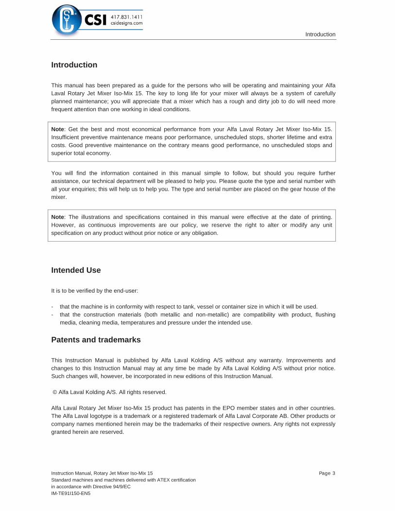
Special Conditions for Safe Use in accordance with the ATEX Certification, Directive 94/9/EC
ATEX Warning:
The unit must not be operated in a vessel having an enclosed volume of greater than 100m3.
Tanks larger than 100 m³
To use Rotary Jet Mixers in tanks larger than 100m³ is possible under certain conditions.
It is necessary to know the current factors such as tank size, cleaning solvent and product.
Additives can be used in the cleaning solvent, or, for example, the tank can be filled with nitrogen. The basic rules are described in the guide "CLC / TR 50404:2003“.
Following a guidance document such as "CLC / TR 50404:2003“ to establish safe use of machinery and process is the users own responsibility and is not covered by the ATEX certification for this product.
ATEX Warning:
The user must address the electrostatic hazards generated from the process of the equipment in accordance with guidance document CLC/TR 50404:2003.

Service and Repair of ATEX Approved Machines
Instruction Manual, Rotary Jet Mixer Iso-Mix 15 Page 21Standard machines and machines delivered with ATEX certificationin accordance with Directive 94/9/ECIM-TE91I150-EN5
Service and Repair of ATEX Approved Machines
In order to ensure compliance with the ATEX regulations for service and repair in accordance with EN 60079-19, all service and repair of ATEX approved machines should be performed by Alfa Laval Tank Equipment, Kolding, Denmark.
Warning: ATEX requirements regarding repair of ATEX approved machines according to EN 60079-19.
A tag with the following labelling information must be attached to the machine:- Repair symbol R- Alfa Laval logo and address- Repair number- Date of repair- Machine serial number
The tag must be laminated and attached to the machine-downpipe outside the tank using a cable tie.
If a customer wishes to carry out service or repair himself, it is the responsibility of the repair shop to ensure that the ATEX requirements are met in any way possible. After performing service or repair, the repair shop thus carries the full responsibility for the ATEX approval of the machine.

Maintenance and Repair
Page 22 Instruction Manual, Rotary Jet Mixer Iso-Mix 15Standard machines and machines delivered with ATEX certification
in accordance with Directive 94/9/ECIM-TE91I150-EN5
Maintenance and Repair
Preventive Maintenance
In order to keep your Rotary Jet Mixer Iso-Mix 15 servicing you as an efficient tool in your tank mixing operations, it is essential to maintain its high performance by following a simple preventive maintenance programme, which will always keep your Rotary Jet Mixer Iso-Mix 15 in good condition.
Good maintenance is careful and regular attention!
The following recommended preventive maintenance is based on Rotary Jet Mixer Iso-Mix 15s working in average conditions. However, you will appreciate that a Rotary Jet Mixer Iso-Mix 15, which has a rough and dirty job to do, will need more frequent attention than one working in ideal conditions. We trust that you willadjust your maintenance programme to suit.
Always use only proper tools. Use Rotary Jet Mixer Iso-Mix 15 standard tool kit. Never force, hammer or pry components together or apart. Always perform all assembly/disassembly steps in the order described in this manual. Never assemble components without previous mixing. This is especially important at all mating surfaces. Work in a clear well lighted work area.
Every 4000 working hours (depending on working conditions)
1. Disassemble mixer as described on the following pages.
2. Clean material build-up and deposits from internal parts with chemical cleaner and/or if desired fine abrasive cloth.
3. Check slide bearings (pos. 28) for wear. If hole is worn oval to max diameter more than 10.4 mm, slide bearing should be replaced. If end face of slide bearing is worn more than x mm into slide bearing, it should be replaced.
Under turbine shaft: x = 1.5 mm
At horizontal shaft: x = 0.5 mm
4. Check collar bushes (pos. 10) in gear frame. If holes are worn oval to max diameter more than 13.4 mm, collar bush should be replaced. How to replace collar bushes, see page 34.
Note: Timely replacement of slide bearings and collar bushes will prevent costly damage to the gearbox.

Maintenance and Repair
Instruction Manual, Rotary Jet Mixer Iso-Mix 15 Page 23Standard machines and machines delivered with ATEX certificationin accordance with Directive 94/9/ECIM-TE91I150-EN5
Maintenance and Repair (continued)
Preventive Maintenance (continued)
6. Check worm wheels (pos. 11 and pos. 33). If extremely worn, they should be replaced.
7. Check main bush (pos. 5). If worn it should be replaced.
8. Assemble machines as described in the following pages.
9. Check that the machine is in operating condition by inserting 3/16" Hex screwdriver (tool no. 134A) in screw in top of turbine shaft and easily turn turbine shaft clockwise. If any resistance is recognised, the machine should be disassembled to localise the cause.
10. Apart from the parts specifically mentioned above, all the remaining wear parts should regularly be inspected for wear. Which parts that are wear parts appear from Reference Lists of Parts, page 44 & 46.

Maintenance and Repair
Page 24 Instruction Manual, Rotary Jet Mixer Iso-Mix 15Standard machines and machines delivered with ATEX certification
in accordance with Directive 94/9/ECIM-TE91I150-EN5
Maintenance and Repair (continued)
Top Assembly
Disassembly
1. Remove 3/16" screws (pos. 17). Loosen and unscrew with a socket wrench (tool no. 462A).
2. Lift off top cone (pos. 1).
3. Remove guide/guide ring (pos. 2). The guide has a groove in the outer diameter. The guide is easily lifted out of the stem by means of two ordinary screwdrivers inserted into the groove.
4. Remove 3/16" screw (pos. 15), spring washer (pos. 16) and washer (pos. 34). To secure impeller against rotation, insert carefully screwdriver (tool no. 134A), through impeller (pos. 4) into a hole in the stem.
5. Pull off impeller (pos. 4).
Reassembly
1. Reinstall impeller (pos. 4). Make sure that impeller is correctly rotated to be pushed onto turbine shaft. Do not try to hammer impeller in position, as this will damage slide bearing under turbine shaft.
2. Mount washer (pos. 34), spring washer (pos. 16) and 3/16" screw (pos. 15) and tighten. To secure impeller against rotation insert carefully screwdriver (tool no. 134A) through impeller (pos. 4) into a hole in the stem.
3. Reinstall guide/guide ring (pos. 2).
4. Mount top cone (pos. 1). Make sure that it is in correct position over guide/guide ring (pos. 2). Rotate top cone to align holes in top cone and stem.
5. Mount and tighten 3/16" screws (pos. 17) with a socket wrench (tool no. 462A).

Maintenance and Repair
Instruction Manual, Rotary Jet Mixer Iso-Mix 15 Page 25Standard machines and machines delivered with ATEX certificationin accordance with Directive 94/9/ECIM-TE91I150-EN5
Maintenance and Repair (continued)
Top Assembly

Maintenance and Repair
Page 26 Instruction Manual, Rotary Jet Mixer Iso-Mix 15Standard machines and machines delivered with ATEX certification
in accordance with Directive 94/9/ECIM-TE91I150-EN5
Maintenance and Repair (continued)
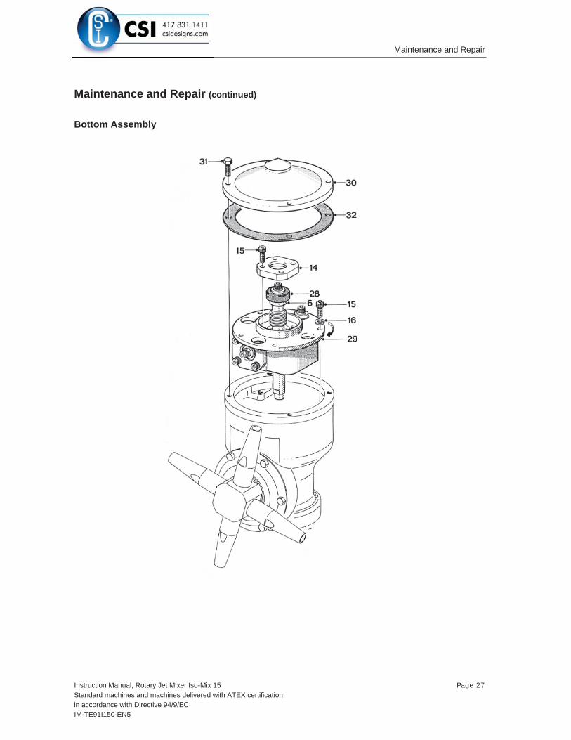
Bottom Assembly
Disassembly
1. Turn machine upside down.
2. Remove 3/16" screws (pos. 31) from bottom cover (pos. 30).
3. Remove bottom cover (pos. 30) and gasket (pos. 32).
4. Remove 3/16" screws (pos. 15) in bearing cover (pos. 14). Carefully push out turbine shaft (pos. 6) from opposite end. Do not try to hammer out turbine shaft, since this can damage slide bearing.
5. Remove 3/16" screws (pos. 15) and spring washers (pos. 16) along the circumference of gear frame (pos. 29). Turn gear frame about 1 cm (½"). Draw out gear subassembly (holes in gear frame are excellent for holding gear subassembly).
Reassembly
1. Reinsert gear subassembly in bottom of machine body. Turn gear frame (pos. 29) to align holes in gear frame and 3/16" threads in body. Mount spring washers (pos. 16) and 3/16" screws (pos. 15) along circumference of gear frame (pos. 29). Tighten screw crosswise.
Note: To secure meshing between gear wheel (pos. 7) and pinion (pos. 9). It might be necessary to rotate slightly either the whole gear subassembly or the gear wheel.
2. Reinsert turbine shaft (pos. 6) with slide bearing carefully through gear wheel (pos. 7). Push carefully slide bearing (pos. 28) into position. Mount bearing cover (pos. 14) with 3/16" screws (pos. 15). Tighten crosswise.
3. Place bottom gasket (pos. 32) and bottom cover (pos. 30).
4. Mount 3/16" screws (pos. 31) and tighten crosswise.
Maintenance and Repair
Instruction Manual, Rotary Jet Mixer Iso-Mix 15 Page 27Standard machines and machines delivered with ATEX certificationin accordance with Directive 94/9/ECIM-TE91I150-EN5
Maintenance and Repair (continued)
Bottom Assembly

Maintenance and Repair
Page 28 Instruction Manual, Rotary Jet Mixer Iso-Mix 15Standard machines and machines delivered with ATEX certification
in accordance with Directive 94/9/ECIM-TE91I150-EN5
Maintenance and Repair (continued)
Hub Subassembly
Disassembly
1. Remove nozzles (pos. 20). Nozzles are untightened with a wrench on the faces of the nozzles.
2. Remove 3/16" screws (pos. 31), hub cover (pos. 19), and gasket (pos. 25).
3. Draw out hub (pos. 21) together with ball retainer with balls (pos. 24) and bevel gear (pos. 18).
4. If ball races (pos. 18.1 and 19.1) in hub cover and in bevel gear are extremely worn, they should be replaced as well as the ball retainer with balls (pos. 24). How to replace ball races see page 36.
Reassembly
1. Slide on hub (pos. 21). Reinsert bevel gear with race (pos. 18) and ball retainer with balls (pos. 24).
2. Mount gasket (pos. 25) and hub cover with race (pos. 19), and set with 3/16" screws (pos. 31). Tighten clockwise.
3. Screw on nozzles (pos. 20) and tighten with wrench.

Maintenance and Repair
Instruction Manual, Rotary Jet Mixer Iso-Mix 15 Page 29Standard machines and machines delivered with ATEX certificationin accordance with Directive 94/9/ECIM-TE91I150-EN5
Maintenance and Repair (continued)
Hub Subassembly

Maintenance and Repair
Page 30 Instruction Manual, Rotary Jet Mixer Iso-Mix 15Standard machines and machines delivered with ATEX certification
in accordance with Directive 94/9/ECIM-TE91I150-EN5
Maintenance and Repair (continued)
Stem Subassembly
Disassembly
1. Place machine in upside-down position.
2. Remove 3/16" screws (pos. 15) in gear wheel (pos. 7). To prevent rotation of stem (pos. 3) mount two3/16" screws in two holes opposite one another in BIG end of stem. Place stem in a vice held by the heads of the two screws.
3. Draw out gear wheel with ball races (pos. 7) and ball retainer with balls (pos. 24).
4. Push out stem (pos. 3).
5. If worn, press out main bush (pos. 5).
If ball races in body (pos. 26.3) and on gear wheel (pos. 7.1) are extremely worn they should be replaced together with ball retainer with balls (pos. 24). How to replace ball races see page 36.
Reassembly
1. If replaced press main bush (pos. 5) into stem (pos. 3).
2. Push stem into body. Turn mixer upside-down.
3. Place ball retainer with balls (pos. 24) and gear wheel (pos. 7) into body on ball race. Rotate gear wheel to check free rotation. Mount gear wheel with 3/16" screws (pos. 15) and tighten crosswise. To prevent rotation of stem (pos. 3) mount two 3/16" screws in two holes opposite one another in BIG end of stem. Place stem in a vice held by the heads of the two screws.

Maintenance and Repair
Instruction Manual, Rotary Jet Mixer Iso-Mix 15 Page 31Standard machines and machines delivered with ATEX certificationin accordance with Directive 94/9/ECIM-TE91I150-EN5
Maintenance and Repair (continued)
Stem Subassembly

Maintenance and Repair
Page 32 Instruction Manual, Rotary Jet Mixer Iso-Mix 15Standard machines and machines delivered with ATEX certification
in accordance with Directive 94/9/ECIM-TE91I150-EN5
Maintenance and Repair (continued)
Gear Subassembly
Disassembly
1. To make a backstop, remount turbine shaft (pos. 6) with slide bearing (pos. 28) into gear frame (pos. 29). Mount bearing cover (pos. 14) with 3/16" screws (pos. 15).
2. Hold turbine shaft (pos. 6) against 1st stage worm wheel (pos. 33) with one hand and loosen 3/16"screws (pos. 15) in pinion (pos. 9) and horizontal shaft (pos. 27) with the other hand.
3. Remove 3/16" screws (pos. 15) in bearing cover (pos. 14) and take out turbine shaft (pos. 6).
4. Draw out horizontal shaft (pos. 27) and 1st stage worm wheel (pos. 33) after removal of 3/16" screw (pos. 15), spring washer (pos. 16) and washer (pos. 34).
5. Draw out pinion (pos. 9) and 2nd stage worm wheel (pos. 11), also freeing journal (pos. 12) after removal of 3/16" screw (pos. 15), spring washer (pos. 16) and washer (pos. 34).
6. Remove bearing cover (pos. 14) and slide bearing (pos. 28) after removal of 3/16" screw (pos. 15).
7. Remove 3/16" screw (pos. 15), spring washer (pos. 16), washer (pos. 34) and slide bearing (pos. 28) from turbine shaft (pos. 6). Use faces on turbine shaft to hold against rotation.
Warning Do not damage driver faces on turbine shaft. Use only proper tools providing a firm grip such as a wrench or a vice.
How to replace collar bushes (pos. 10), see page 34.
Reassembly
1. Mount slide bearing (pos. 28) on turbine shaft (pos. 6) and secure with washer (pos. 34), spring washer (pos. 16) and 3/16" screw (pos. 15). Hold turbine shaft in a vice or with wrench on driver faces and tighten.
2. Push slide bearing (pos. 28) for horizontal shaft (pos. 27) into gear frame (pos. 29) and fix bearing cover (pos. 14) with 3/16" screws (pos. 15). Tighten crosswise.
3. Insert 2nd stage worm wheel (pos. 11), pinion (pos. 9) and journal (pos. 12). Mount washer (pos. 34), spring washer (pos. 16) and fix with 3/16" screw (pos. 15). Check rotation.

Maintenance and Repair
Instruction Manual, Rotary Jet Mixer Iso-Mix 15 Page 33Standard machines and machines delivered with ATEX certificationin accordance with Directive 94/9/ECIM-TE91I150-EN5
Maintenance and Repair (continued)
Gear Subassembly
Note: It is important that the screw holding the pinion is fastened to a torque moment of 5 Nm, to secure it from loosening.
1. Insert 1st stage worm wheel (pos. 33) and horizontal shaft (pos. 27). Mount washer (pos. 34), spring washer (pos. 16) and fix with 3/16" screw (pos. 15). Check rotation.
2. Reinstall turbine shaft (pos. 6) in gear frame as mentioned under disassembly, point 1.
3. Hold turbine shaft (pos. 6) against 1st stage worm wheel and tighten 3/16" screws (pos. 15) in horizontal shaft (pos. 27) and pinion (pos. 9).
4. Remove turbine shaft (pos. 6) with slide bearing (pos. 28) before gear subassembly is inserted in machine body.

Maintenance and Repair
Page 34 Instruction Manual, Rotary Jet Mixer Iso-Mix 15Standard machines and machines delivered with ATEX certification
in accordance with Directive 94/9/ECIM-TE91I150-EN5
Maintenance and Repair (continued)
Replacement of Collar Bushes
1. Place gear frame (pos. 29) upside down with a firm support under the flange. Use for instance jaws of a vice. Do not clamp on machined surfaces. With pusher (tool no. TE81B033, see page 40) knock out collar bush.
2. Turn gear frame to upright position and hold over support such as flat steel bar clamped in a vice. Knock out collar bush with pusher.
3. Turn gear frame 90o and hold over support. Knock out collar bush with pusher.
Warning To avoid risk of deforming gear frame, it is utmost important that it is supported while the collar bushes are being knocked out.
4. Clean holes and push in new collar bushes into gear frame.

Maintenance and Repair
Instruction Manual, Rotary Jet Mixer Iso-Mix 15 Page 35Standard machines and machines delivered with ATEX certificationin accordance with Directive 94/9/ECIM-TE91I150-EN5
Maintenance and Repair (continued)
Replacement of Collar Bushes
Removal of old collar bushes

Maintenance and Repair
Page 36 Instruction Manual, Rotary Jet Mixer Iso-Mix 15Standard machines and machines delivered with ATEX certification
in accordance with Directive 94/9/ECIM-TE91I150-EN5
Maintenance and Repair (continued)
Replacement of Ball Races
In body
1.A With big end downwards knock several times body with bearings (pos. 26) hard against firm wooden support until ball race (pos. 26.3) drops out.
1.B If it is not possible to knock out ball race in this way, it is necessary first to screw out main collar lower (pos. 26.2) – see page 38. Carefully push off old ball race without damaging main collar lower. Use mandrel and firm support.
Before mounting of new ball race, main collar lower (pos. 26.2) must be remounted into body – see page 38.
2. Clean surfaces and place ball race (pos. 26.3) on main collar lower (pos. 26.2). Press by hand as long as possible. By means of a tube mandrel or if desired wooden block, carefully hammer ball races home.
Ball races must not project over end face of main collar lower. To avoid tilting mandrel must push along the whole circumference of ball race. Do not damage surface of ball race.
On Gear wheel
1. Place gear wheel with ball race (pos. 7) on support. Support only under ball race (pos. 7.1). With mandrel press off old ball race.
2. Clean surfaces and press on new ball race. Ball race must be pressed fully home on gear. Press parallel. Use press or vice. Do not damage surface of ball race.
In Hub cover
1. Place hub cover with ball race (pos. 19) on support. Carefully knock out old ball race by means of small mandrel or if desired screwdriver. Knock several times around the circumference to avoid tilting.
2. Clean surfaces and press in new ball race. Ball race must be pressed fully home. Press parallel. Do not damage surface of ball race.

Maintenance and Repair
Instruction Manual, Rotary Jet Mixer Iso-Mix 15 Page 37Standard machines and machines delivered with ATEX certificationin accordance with Directive 94/9/ECIM-TE91I150-EN5
Maintenance and Repair (continued)
Replacement of Ball races

Maintenance and Repair
Page 38 Instruction Manual, Rotary Jet Mixer Iso-Mix 15Standard machines and machines delivered with ATEX certification
in accordance with Directive 94/9/ECIM-TE91I150-EN5
Maintenance and Repair (continued)
Replacement of Main Collars
Although normally exposed to very limited wear, it is possible to replace main collars (pos. 26.1 and 26.2) and hub liner (pos. 26.4) in body. The procedure to do this is described below.
Main collar upper
1. Place body (pos. 26) in a vice upright position. Do not clamp on machined faces. Insert tool (see page 41) into main collar upper (pos. 26.1). Unscrew main collar.
2. Carefully clean thread and recess in body. Do not damage special thread in body. Recess must be absolutely clean.
3. Make sure that new main collar is clean and free from impurities.
4. Screw in new main collar. Attention should be given to make sure that thread is in correct engagement before screwing in main collar.
5. Tighten main collar fully home and tighten up.
6. Check that main collar is fully home: install stem, ball retainer with balls and gear wheel (see page 30). Check that there is sufficient axial clearance to allow for free rotation of stem.
Main collar lower
1. Place body in a vice in upside down position, and repeat procedure described above.
Warning Thread on main collar lower is left-handed.
Hub Liner
1. Place body in a vice. Insert two ordinary screwdrivers behind hub liner and press it out.
2. Push on new hub liner.

Maintenance and Repair
Instruction Manual, Rotary Jet Mixer Iso-Mix 15 Page 39Standard machines and machines delivered with ATEX certificationin accordance with Directive 94/9/ECIM-TE91I150-EN5
Maintenance and Repair (continued)
Replacement of Main Collars

Tools
Page 40 Instruction Manual, Rotary Jet Mixer Iso-Mix 15Standard machines and machines delivered with ATEX certification
in accordance with Directive 94/9/ECIM-TE91I150-EN5
Tools
Standard Tool kit for IM 15 Rotary Jet Mixer, Article No. TE81B055
Tool No. Description Pcs.TE134 Hex key for 3/16" screw 1TE134A Screw driver for 3/16"screw 2TE462A 8mm Socket Wrench w.pin 1
Sketch of Tools for replacement of Collar bush
Available on requestTE81B033 Pusher f. 1½" machines

Tools
Instruction Manual, Rotary Jet Mixer Iso-Mix 15 Page 41Standard machines and machines delivered with ATEX certificationin accordance with Directive 94/9/ECIM-TE91I150-EN5
Tools (continued)
Sketch of Tools for replacement of Main collars
Available on requestTE81B129 Tool f. upper Collar (1½"TCM) Compl.TE81B130 Tool f. lower Collar (1½"TCM) Compl.

Trouble Shooting Guide
Page 42 Instruction Manual, Rotary Jet Mixer Iso-Mix 15Standard machines and machines delivered with ATEX certification
in accordance with Directive 94/9/ECIM-TE91I150-EN5
Trouble Shooting Guide
Symptom: Slow rotation or failure of machine to rotate
Possible Causes Fault finding
No or insufficient liquid flow a) Check if supply valve is fully open
b) Check if inlet pressure to machine is correct,
c) Check supply line and filter for restriction/clogging
d) Remove nozzles and check for clogging. If blocked, carefully clean nozzle without damaging stream strengtheners and nozzle tip.
e) Remove top cone guide and impeller (see page 24)and check for clogging in impeller area.
f) If large particles repeatedly get jammed in the machine, install filter or reduce mesh size of installed filter in supply line.
Foreign material or material build-up Insert Hex screwdriver in screw in top of turbine shaft and easily turn turbine shaft clockwise. If any resistance is recognised, disassemble machine in order to localise the cause.
a) Impeller jammed Remove guide and impeller (see page 24) and remove foreign material.
b) Turbine shaft - sluggish in main bush Remove turbine shaft (see page 26) and clean main bush.
c) Bevel gears jammed Remove top cone and hub subassembly (see page 28). Clean teeth on stem and bevel gear.
d) Stem jammed/sluggish Remove gear subassembly (see page 26). Check free rotation of stem. Remove stem (see page 30). Remove foreign material/material build-up on stem and inside main collars. Clean ball races and ball retainer with balls. Also clean main bush.

Trouble Shooting Guide
Instruction Manual, Rotary Jet Mixer Iso-Mix 15 Page 43Standard machines and machines delivered with ATEX certificationin accordance with Directive 94/9/ECIM-TE91I150-EN5
Trouble Shooting Guide (continued)
Possible Causes Fault finding
e) Gearbox jammed/sluggish Remove foreign material from gearbox. Check rotation of shafts. If restriction is recognized, disassemble gearbox (see page 32) and remove material build up, especially on 2nd stage worm wheel and mating collar bushes.
f) Hub jammed/sluggish Disassemble hub subassembly (see page 28). Remove foreign material inside hub. Clean ball races and ball retainer with balls. Also clean nose of body.
Wear
a) Slide bearings See page 22.
b) Main bush See page 23.
c) Worm wheels See page 23.
d) Collar bushes See page 22.
e) Turbine shaft Check clearance in main bush and in slide bearing. Transverse movement should not exceed 0.5 mm. Also inspect worm wheel for wear.
f) Horizontal shaft Check clearance in collar bushes. Transverse movement should not exceed 0.5 mm. Also inspect worm for wear.
Mechanical defects
a) Worm wheels. Teeth broken Replace worm wheel.
b) Worm wheel can rotate on horizontal shaft/pinion due to damaged driver faces Replace worm wheel.
c) Damaged teeth on gear Inspect teeth on stem and bevel gear for deformation. Mount hub and stem in body (se page 286 and 18). Hold body in upside down position and rotate hub to check that bevel gears can work together. If damaged: Replace stem and/or bevel gear.

IM 15 Rotary Jet Mixer with 4 nozzles
Page 44 Instruction Manual, Rotary Jet Mixer Iso-Mix 15Standard machines and machines delivered with ATEX certification
in accordance with Directive 94/9/ECIM-TE91I150-EN5
IM 15 Rotary Jet Mixer with 4 nozzles
Reference List of Parts
Pos. Ref.No. No/Unit Description Material Remarks1 TE21D500 1 Top Cone 1½" BSP Stainless steel Spare part
TE21D501 1 Top Cone 1½" NPT Stainless steel Spare part2 TE703 1 Guide 100% Stainless steel Spare part
TE803-0 1 Guide ring 0% Stainless steel Spare part3 TE21B526 1 Stem Stainless steel Spare part4 TE31B512 1 Impeller 100% Stainless steel Spare part5 TE21A526 1 Main bush Polymer Wear part6 TE31B511 1 Turbine shaft Stainless steel Wear part7 TE31B304 1 Gear wheel w. ball race Stainless steel Spare part7.1 TE31B510 Ball race Stainless steel Wear part9 TE814 1 Pinion Stainless steel Spare part10 TE21A586 3 Collar bush Polymer Wear part11 TE21A367 1 Worm wheel w. reinforcement Polymer Wear part
TE21A364 1 Worm wheel E-gear Polymer Wear part12 TE817 1 Journal Stainless steel Spare part13 TE719A 3 Washer Stainless steel Spare part14 TE731 2 Bearing cover Stainless steel Spare part15 TE118 22 Screw Stainless steel Spare part16 TE156 8 Spring washer Stainless steel Spare part17 TE402H 6 Screw Stainless steel Spare part18 TE31B306 1 Bevel gear w. ball race Stainless steel Spare part18.1 TE31B510 Ball race Stainless steel Wear part19 TE31B305 1 Hub cover w. ball race Stainless steel Spare part19.1 TE31B510 Ball race Stainless steel Wear part20 TE50A006 4 Nozzle, ø6 mm Stainless steel Spare part
TE50A007 4 Nozzle, ø7 mm Stainless steel Spare partTE50A008 4 Nozzle, ø8 mm Stainless steel Spare part
21 TE21C536 1 Hub for 4 nozzle Stainless steel Spare part24 TE31B303 2 Ball retainer w. balls Polymer/ceramics Wear part25 TE21D562 1 Hub gasket Polymer/elastomer Spare part26 1 Body Stainless steel Not available26.1 TE21B520 1 Main collar upper Polymer Wear part26.2 TE21B521 1 Main collar lower Polymer Wear part26.3 TE31B510 Ball race Stainless steel Wear part26.4 TE21D522 1 Hub collar Polymer Wear part27 TE828Z 1 Horizontal shaft Stainless steel Wear part
TE21A550 1 Horizontal shaft E-gear Stainless steel Wear part28 TE21A571 2 Slide bearing Polymer Wear part29 TE730 1 Gear frame Stainless steel Spare part30 TE21D350 1 Bottom cover compl. Stainless steel Spare part31 TE421H 10 Hex Screw Stainless steel Spare part32 TE21D563 1 Bottom gasket Elastomer/polymer Spare part33 TE21A367 1 Worm wheel w. reinforcement Polymer Wear part34 TE31B515 1 Washer Stainless steel Spare part
Possible configurations marked Please note that some of the polymer parts are in PEEK. PEEK is not resistant to concentrated sulfuric acid.

IM 15 Rotary Jet Mixer with 4 nozzles
Instruction Manual, Rotary Jet Mixer Iso-Mix 15 Page 45Standard machines and machines delivered with ATEX certificationin accordance with Directive 94/9/ECIM-TE91I150-EN5
IM 15 Rotary Jet Mixer with 4 nozzles
Cross Sectional Drawing

IM 15 Rotary Jet Mixer with 2 nozzles
Page 46 Instruction Manual, Rotary Jet Mixer Iso-Mix 15Standard machines and machines delivered with ATEX certification
in accordance with Directive 94/9/ECIM-TE91I150-EN5
IM 15 Rotary Jet Mixer with 2 nozzles
Reference List of Parts
Pos. Ref.No. No/Unit Description Material Remarks1 TE21D500 1 Top Cone 1½" BSP Stainless steel Spare part
TE21D501 1 Top Cone 1½" NPT Stainless steel Spare part2 TE703 1 Guide 100% Stainless steel Spare part
TE803-0 1 Guide ring 0% Stainless steel Spare part3 TE21B526 1 Stem Stainless steel/polymer Spare part4 TE31B512 1 Impeller 100% Stainless steel Spare part5 TE21A526 1 Main bush Polymer Wear part6 TE31B511 1 Turbine shaft Stainless steel Wear part7 TE31B304 1 Gear wheel w. ball race Stainless steel Spare part7.1 TE31B510 Ball race Stainless steel Wear part9 TE814 1 Pinion Stainless steel Spare part10 TE21A586 3 Collar bush Polymer Wear part11 TE21A367 1 Worm wheel w. reinforcement Polymer Wear part
TE21A364 1 Worm wheel E-gear Polymer Wear part12 TE817 1 Journal Stainless steel Spare part13 TE719A 3 Washer Stainless steel Spare part14 TE731 2 Bearing cover Stainless steel Spare part15 TE118 22 Screw Stainless steel Spare part16 TE156 8 Spring washer Stainless steel Spare part17 TE402H 6 Screw Stainless steel Spare part18 TE31B306 1 Bevel gear w. ball race Stainless steel Spare part18.1 TE31B510 Ball race Stainless steel Wear part19 TE31B305 1 Hub cover w. ball race Stainless steel Spare part19.1 TE31B510 Ball race Stainless steel Wear part20 TE50B008 2 Nozzle, ø8 mm Stainless steel Spare part
TE50B009 2 Nozzle, ø9 mm Stainless steel Spare partTE50B010 2 Nozzle, ø10 mm Stainless steel Spare partTE50B011 2 Nozzle, ø11 mm Stainless steel Spare part
21 TE21B536 1 Hub for 2 nozzle Stainless steel Spare part22 TE448 1 Split pin for 2 nozzle Stainless steel Spare part23 TE724-2-15 1 Hub nozzle part for 2 nozzle Stainless steel Spare part24 TE31B303 2 Ball retainer with balls Polymer/ceramics Wear part25 TE21D562 1 Hub gasket Polymer/elastomer Spare part26 1 Body Stainless steel Not available26.1 TE21B520 1 Main collar upper Polymer Wear part26.2 TE21B521 1 Main collar lower Polymer Wear part26.3 TE31B510 Ball race Stainless steel Wear part26.4 TE21D522 1 Hub collar Polymer Wear part27 TE828Z 1 Horizontal shaft Stainless steel Wear part
TE21A550 1 Horizontal shaft E-gear Stainless steel Wear part28 TE21A571 2 Slide bearing Polymer Wear part29 TE730 1 Gear frame Stainless steel Spare part30 TE21D350 1 Bottom cover compl. Stainless steel Spare part31 TE421H 10 Hex Screw Stainless steel Spare part32 TE21D563 1 Bottom gasket Elastomer/polymer Spare part33 TE21A367 1 Worm wheel w. reinforcement Polymer Wear part34 TE31B515 1 Washer Stainless steel Spare part
Possible configurations marked Please note that some of the polymer parts are in PEEK. PEEK is not resistant to concentrated sulfuric acid.

IM 15 Rotary Jet Mixer with 2 nozzles
Instruction Manual, Rotary Jet Mixer Iso-Mix 15 Page 47Standard machines and machines delivered with ATEX certificationin accordance with Directive 94/9/ECIM-TE91I150-EN5
IM 15 Rotary Jet Mixer with 2 nozzles
Cross Sectional Drawing

Service intervals
Page 48 Instruction Manual, Rotary Jet Mixer Iso-Mix 15Standard machines and machines delivered with ATEX certification
in accordance with Directive 94/9/ECIM-TE91I150-EN5
Service intervals
* Note: The service intervals are recommended on the basis of pure liquids. When liquids contain particles and other kind of abrasives, we recommend shorter service intervals depending on the actual running conditions.
Standard Spare Part Service Kits and Tool Kits
Standard Spare Part Service Kit for IM 15 Rotary Jet Mixer, Article No. TE31B299
Part No. Description No.TE21A367 Worm wheel w. reinforcement 2 pcs.TE21A526 Main bush 1 pc.TE21A571 Slide bearing 2 pcs.TE21A586 Collar bush 3 pcs.TE31B303 Ball retainer with balls 2 pcs.TE31B510 Ball race 4 pcs.TE31B511 Turbine shaft 1 pc.TE828Z Horizontal shaft 1 pc.
Standard Tool Kit for IM 15 Rotary Jet Mixer, Article No. TE81B055
Part No. Description No.TE134 Hex key for 3/16" screw 1 pc.TE134A Screw driver for 3/16"screw 2 pcs.TE462A 8mm Socket Wrench w.pin 1 pc.
Special Tools for IM 15 Rotary Jet MixerAvailable on request:Part No. Description No.TE81B033 Pusher f. 1½" machines 1 pc.TE81B129 Tool f. upper Collar (1½"TCM) Compl. 1 pc.TE81B130 Tool f. lower Collar (1½"TCM) Compl. 1 pc.
4000 hour(*)
4000 hour(*)
As per above:Service Kit:TE31B299
(*)Service check
4000 hour(*)
As per above:Service Kit:TE31B299
(*)Service check
As per above:Service Kit:TE31B299
(*)Service check

General Information
Instruction Manual, Rotary Jet Mixer Iso-Mix 15 Page 49Standard machines and machines delivered with ATEX certificationin accordance with Directive 94/9/ECIM-TE91I150-EN5
General Information
How to Order Spare Parts
On the Cross Sectional Drawing as well as on all instruction drawings, the individual parts have a pos. number which is the same on all drawings. From the pos. number, the part is easily identified in the Reference lists of Parts, page 44 & 46.
Individual parts should always be ordered from the Reference lists of parts. Reference number and description should be clearly stated.
Please also quote the type of mixer and serial number. This will help us to help you. The type and serial number are stamped on the body of the Rotary Jet Mixer Iso-Mix 15.
Service and Repair
Upon every return of a product, no matter if for modifications or repair, it is necessary to contact your local Alfa Laval office to guarantee a quick execution of your request.
You will receive instructions regarding the return procedure from your local Alfa Laval office. Be sure to follow the instructions closely.
How to contact Alfa Laval Tank Equipment
For further information please feel free to contact:
Alfa Laval Tank EquipmentAlfa Laval Kolding A/S31, Albuen - DK 6000 Kolding - Denmark
Registration number: 30938011
Tel switchboard: +45 79 32 22 00 - Fax switchboard: +45 79 32 25 80
www.toftejorg.com , www.alfalaval.dk - [email protected]
Contact details for all countries are continually updated on our websites.

Declaration of Conformity
Page 50 Instruction Manual, Rotary Jet Mixer Iso-Mix 15Standard machines and machines delivered with ATEX certification
in accordance with Directive 94/9/ECIM-TE91I150-EN5
Declaration of Conformity

How to contact Alfa LavalContact details for all countries arecontinually updated on our website.Please visit www.alfalaval.com to access the information directly.
© Alfa Laval Corporate ABThis document and its contents is owned by Alfa Laval Corporate AB and protected by laws governing intellectual property and thereto related rights. It is the responsibility of the user of thisdocument to comply with all applicable intellectual property laws. Without limiting any rights related to this document, no part of this document may be copied, reproduced or transmitted in anyform or by any means (electronic, mechanical, photocopying, recording, or otherwise), or for any purpose, without the expressed permission of Alfa Laval Corporate AB. Alfa Laval Corporate ABwill enforce its rights related to this document to the fullest extent of the law, including the seeking of criminal prosecution.


![Stand Mixer - ProductReview.com.au · 1. Place the stand mixer on a level, stable surface. Ensure that the rotary speed control is in the OFF [ 0 ] position before plugging the mixer](https://static.fdocuments.net/doc/165x107/5f32ad36a1c6a5639a4bc443/stand-mixer-1-place-the-stand-mixer-on-a-level-stable-surface-ensure-that-the.jpg)