Rotary Encoders - A Tech Authority · Rotary encoders for separate shaft coupling This catalog...
100
November 2015 Rotary Encoders
Transcript of Rotary Encoders - A Tech Authority · Rotary encoders for separate shaft coupling This catalog...

November 2015
Rotary Encoders

2
Rotary encoder with mounted stator coupling
Rotary encoders for separate shaft coupling
This catalog supersedes all previous editions, which thereby become invalid.The basis for ordering from HEIDENHAIN is always the catalog edition valid when the contract is made.
Standards (ISO, EN, etc.) apply only where explicitly stated in the catalog.
Rotary encoders from HEIDENHAIN serve as measuring sensors for rotary motion, angular velocity, and when used in conjunction with mechanical measuring standards such as lead screws, for linear motion. Application areas include electrical motors, machine tools, printing machines, woodworking machines, textile machines, robots and handling devices, as well as various types of measuring, testing, and inspection devices.
The high quality of the sinusoidal incremental signals permits high interpolation factors for digital speed control.
Electronic handwheel
Comprehensive descriptions of all available interfaces as well as general electrical information are included in the Interfaces for HEIDENHAIN Encoders brochure, ID 1078628-xx.
Information on• Encoders for servo drives• Angle encoders with integral bearing• Angle encoders without integral bearing• Modular magnetic encoders• Linear encoders for numerically
controlled machine tools• Exposed linear encoders• Interface electronics• HEIDENHAIN controls• Interfaces of HEIDENHAIN Encodersis available upon request as well as on the Internet at www.heidenhain.de.

Introduction
Selection guide 4
Measuring principles, accuracy 12
Mechanical design types and mounting Rotary encoders with stator coupling 14
Rotary encoders for separate shaft coupling 17
Shaft couplings 21
Safety-related position measuring systems 24General mechanical information 26
Specifications Absolute rotary encoders Incremental rotary encoders
Mounted stator coupling ECN 1000/EQN 1000 series ERN 1000 series 28
ECN 400/EQN 400 series ERN 400 series 32
ECN 400 F/EQN 400 F series – 40ECN 400 M/EQN 400 M series –
ECN 400 S/EQN 400 S series –
ECN 400/EQN 400 series with fieldbus
– 42
ECN 400/EQN 400 series with universal stator coupling
ERN 400 series with universal stator coupling
44
ECN 100 series ERN 100 series 48
Separate shaft coupling; synchro flange
ROC/ROQ 1000 series ROD 1000 series 50
ROC/ROQ 400 seriesRIC/RIQ 400 series
ROD 400 series 54
ROC 400 F/ROQ 400 F series – 62ROC 400 M/ROQ 400 M series –
ROC 400 S/ROQ 400 S series –
ROC/ROQ 400 series with fieldbus
– 64
ROC 425 series with high accuracy
– 66
Separate shaft coupling; clamping flange
ROC/ROQ 400 seriesRIC/RIQ 400 series
ROD 400 series 68
ROC 400 F/ROQ 400 F series – 72ROC 400 M/ROQ 400 M series –
ROC 400 S/ROQ 400 S series –
ROC/ROQ 400 series with fieldbus
– 74
Separate shaft coupling; fastening by flange/base
– ROD 1930Sturdy design
76
Handwheels – HR 1120 78Electrical connection
Interfaces and pin layouts
Incremental signals 80
Position values 85
Cables and connecting elements 91
Interface electronics 95Diagnostic and testing equipment 97
Contents

4
Selection guideRotary encoders for standard applications
Rotary Encoders Absolute Incremental Singleturn Multiturn 4096 revolutions
Interface EnDat FanucMitsubishiSiemens
SSI PROFIBUS-DPPROFINET IO
EnDat FanucMitsubishiSiemens
SSI PROFIBUS-DPPROFINET IO
« TTL « TTL « HTL » 1 VPP
With mounted stator coupling
ECN/EQN/ERN 1000 series ECN 1023 – ECN 1023 – EQN 1035 – EQN 1025 – ERN 1020 – ERN 1030 ERN 1080 28Positions/rev: 23 bitsEnDat 2.2/22
ECN 1013Positions/rev: 13 bitsEnDat 2.2/01
Positions/rev: 13 bits Positions/rev: 23 bitsEnDat 2.2/22
EQN 1025Positions/rev: 13 bitsEnDat 2.2/01
Positions/rev: 13 bits
100 to 3600 lines
ERN 10701000/2500/ 3600 lines
1)
100 to 3600 lines
100 to 3600 lines
ECN/EQN/ERN 400 series ECN 425 ECN 425 F ECN 413 – EQN 437 EQN 437 F EQN 4253) – ERN 420 ERN 4602) ERN 430 ERN 480 32Positions/rev: 25 bitsEnDat 2.2/22
ECN 413Positions/rev: 13 bitsEnDat 2.2/01
Positions/rev: 25 bitsFanuc ai
ECN 425 MPositions/rev: 25 bitsMitsubishi
ECN 424 SPositions/rev: 24 bitsDRIVE-CLiQ
Positions/rev: 13 bits Positions/rev: 25 bitsEnDat 2.2/22
EQN 4253)
Positions/rev: 13 bitsEnDat 2.2/01
Positions/rev: 25 bitsFanuc ai
EQN 435 MPositions/rev: 23 bitsMitsubishi
EQN 436 SPositions/rev: 24 bitsDRIVE-CLiQ
Positions/rev: 13 bits
250 to 5000 lines
250 to 5000 lines
250 to 5000 lines
1000 to 5000 lines
ECN/EQN 400 series with fieldbus
– – – ECN 413 – – – EQN 425 – – – – 42Positions/rev: 13 bits Positions/rev:
13 bits
ECN/EQN/ERN 400 series with universal stator coupling
ECN 425 – ECN 413 – EQN 437 – EQN 425 – ERN 420 ERN 4602) ERN 430 ERN 480 44Positions/rev: 25 bitsEnDat 2.2/22
ECN 413Positions/rev: 13 bitsEnDat 2.2/01
Positions/rev: 13 bits Positions/rev: 25 bitsEnDat 2.2/22
EQN 425Positions/rev: 13 bitsEnDat 2.2/01
Positions/rev: 13 bits
250 to 5000 lines
250 to 5000 lines
250 to 5000 lines
1000 to 5000 lines
ECN/ERN 100 series ECN 125 – – – – – – – ERN 120 – ERN 130 ERN 180 48Positions/rev: 25 bitsEnDat 2.2/22
ECN 113Positions/rev: 13 bitsEnDat 2.2/01
1000 to 5000 lines
1000 to 5000 lines
1000 to 5000 lines
1) Up to 36 000 signal periods through integrated 5/10-fold interpolation (higher interpolation on request)2) Voltage supply 10 V to 30 V DC3) Also with TTL or HTL signal transmission

5
Rotary Encoders Absolute Incremental Singleturn Multiturn 4096 revolutions
Interface EnDat FanucMitsubishiSiemens
SSI PROFIBUS-DPPROFINET IO
EnDat FanucMitsubishiSiemens
SSI PROFIBUS-DPPROFINET IO
« TTL « TTL « HTL » 1 VPP
With mounted stator coupling
ECN/EQN/ERN 1000 series ECN 1023 – ECN 1023 – EQN 1035 – EQN 1025 – ERN 1020 – ERN 1030 ERN 1080 28Positions/rev: 23 bitsEnDat 2.2/22
ECN 1013Positions/rev: 13 bitsEnDat 2.2/01
Positions/rev: 13 bits Positions/rev: 23 bitsEnDat 2.2/22
EQN 1025Positions/rev: 13 bitsEnDat 2.2/01
Positions/rev: 13 bits
100 to 3600 lines
ERN 10701000/2500/ 3600 lines
1)
100 to 3600 lines
100 to 3600 lines
ECN/EQN/ERN 400 series ECN 425 ECN 425 F ECN 413 – EQN 437 EQN 437 F EQN 4253) – ERN 420 ERN 4602) ERN 430 ERN 480 32Positions/rev: 25 bitsEnDat 2.2/22
ECN 413Positions/rev: 13 bitsEnDat 2.2/01
Positions/rev: 25 bitsFanuc ai
ECN 425 MPositions/rev: 25 bitsMitsubishi
ECN 424 SPositions/rev: 24 bitsDRIVE-CLiQ
Positions/rev: 13 bits Positions/rev: 25 bitsEnDat 2.2/22
EQN 4253)
Positions/rev: 13 bitsEnDat 2.2/01
Positions/rev: 25 bitsFanuc ai
EQN 435 MPositions/rev: 23 bitsMitsubishi
EQN 436 SPositions/rev: 24 bitsDRIVE-CLiQ
Positions/rev: 13 bits
250 to 5000 lines
250 to 5000 lines
250 to 5000 lines
1000 to 5000 lines
ECN/EQN 400 series with fieldbus
– – – ECN 413 – – – EQN 425 – – – – 42Positions/rev: 13 bits Positions/rev:
13 bits
ECN/EQN/ERN 400 series with universal stator coupling
ECN 425 – ECN 413 – EQN 437 – EQN 425 – ERN 420 ERN 4602) ERN 430 ERN 480 44Positions/rev: 25 bitsEnDat 2.2/22
ECN 413Positions/rev: 13 bitsEnDat 2.2/01
Positions/rev: 13 bits Positions/rev: 25 bitsEnDat 2.2/22
EQN 425Positions/rev: 13 bitsEnDat 2.2/01
Positions/rev: 13 bits
250 to 5000 lines
250 to 5000 lines
250 to 5000 lines
1000 to 5000 lines
ECN/ERN 100 series ECN 125 – – – – – – – ERN 120 – ERN 130 ERN 180 48Positions/rev: 25 bitsEnDat 2.2/22
ECN 113Positions/rev: 13 bitsEnDat 2.2/01
1000 to 5000 lines
1000 to 5000 lines
1000 to 5000 lines
1) Up to 36 000 signal periods through integrated 5/10-fold interpolation (higher interpolation on request)2) Voltage supply 10 V to 30 V DC3) Also with TTL or HTL signal transmission
Intr
od
uct
ion
48
ERN 430 ERN 4801000 to 5000
28
42

6
Rotary encoders for standard applications
Rotary encoders Absolute Incremental Singleturn Multiturn 4096 revolutions
Interface EnDat FanucMitsubishiSiemens
SSI PROFIBUS-DPPROFINET IO
EnDat FanucMitsubishiSiemens
SSI PROFIBUS-DPPROFINET IO
« TTL « TTL « HTL » 1 VPP
For separate shaft coupling, with synchro flange
ROC/ROQ/ROD 1000 series ROC 1023 – ROC 1013 – ROQ 1035 – ROQ 1025 – ROD 1020 – ROD 1030 ROD 1080 50Positions/rev: 23 bitsEnDat 2.2/22
ROC 1013Positions/rev: 13 bitsEnDat 2.2/01
Positions/rev: 13 bits Positions/rev: 23 bitsEnDat 2.2/22
ROQ 1025Positions/rev: 13 bitsEnDat 2.2/01
Positions/rev: 13 bits
100 to 3600 lines
ROD 10701000/2500/ 3600 lines
2)
100 to 3600 lines
100 to 3600 lines
ROC/ROQ/ROD 400 RIC/RIQ 400 seriesWith synchro flange
ROC 425 ROC 425 F ROC 413 – ROQ 437 ROQ 437 F ROQ 425 – ROD 426 ROD 4663) ROD 436 ROD 486 54Positions/rev: 25 bitsEnDat 2.2/22Functional safety upon request
ROC 413Positions/rev: 13 bitsEnDat 2.2/01
RIC 418Positions/rev: 18 bitsEnDat 2.1/01
Positions/rev: 25 bitsFanuc ai
ROC 425 MPositions/rev: 25 bitsMitsubishi
ROC 424 SPositions/rev: 24 bitsDRIVE-CLiQFunctional safety upon request
Positions/rev: 13 bits Positions/rev: 25 bitsEnDat 2.2/22Functional safety upon request
ROQ 425Positions/rev: 13 bitsEnDat 2.2/01
RIQ 430Positions/rev: 18 bitsEnDat 2.1/01
Positions/rev: 25 bitsFanuc ai
ROQ 435 MPositions/rev: 23 bitsMitsubishi
ROQ 436 SPositions/rev: 24 bitsDRIVE-CLiQFunctional safety upon request
Positions/rev: 13 bits
50 to 5000 lines
1) 50 to 5000 lines2)
50 to 5000 lines
1000 to 5000 lines
ROC/ROQ 400 series with fieldbus
– – – ROC 413 – – – ROQ 4254) – – – – 64Positions/rev: 13 bits Positions/rev:
13 bits
ROC 425For high accuracy
ROC 425 – – – – – – – – – – – 66Positions/rev: 25 bitsEnDat 2.2/01
For separate shaft coupling, with clamping flange
ROC/ROQ/ROD 400 RIC/RIQ 400 seriesWith clamping flange
ROC 425 ROC 425 F ROC 413 – ROQ 437 ROQ 437 F ROQ 425 – ROD 420 – ROD 430 ROD 480 68Positions/rev: 25 bitsEnDat 2.2/22Functional safety upon request
ROC 413Positions/rev: 13 bitsEnDat 2.2/01
RIC 418Positions/rev: 18 bitsEnDat 2.1/01
Positions/rev: 25 bitsFanuc ai
ROC 425 MPositions/rev: 25 bitsMitsubishi
ROC 424 SPositions/rev: 24 bitsDRIVE-CLiQFunctional safety upon request
Positions/rev: 13 bits Positions/rev: 25 bitsEnDat 2.2/22Functional safety upon request
ROQ 4254)
Positions/rev: 13 bitsEnDat 2.2/01
RIQ 430Positions/rev: 18 bitsEnDat 2.1/01
Positions/rev: 25 bitsFanuc ai
ROQ 435 MPositions/rev: 23 bitsMitsubishi
ROQ 436 SPositions/rev: 24 bitsDRIVE-CLiQFunctional safety upon request
Positions/rev: 13 bits
50 to 5000 lines
50 to 5000 lines
1000 to 5000 lines
ROC/ROQ 400 series with fieldbus
– – – ROC 413 – – – ROQ 425 – – – – 74Positions/rev: 13 bits Positions/rev:
13 bits
1) Up to 10 000 signal periods through integrated 2-fold interpolation2) Up to 36 000 signal periods through integrated 5/10-fold interpolation (higher interpolation on request)3) Voltage supply 10 V to 30 V DC4) Also with TTL or HTL signal transmission

7
Rotary encoders Absolute Incremental Singleturn Multiturn 4096 revolutions
Interface EnDat FanucMitsubishiSiemens
SSI PROFIBUS-DPPROFINET IO
EnDat FanucMitsubishiSiemens
SSI PROFIBUS-DPPROFINET IO
« TTL « TTL « HTL » 1 VPP
For separate shaft coupling, with synchro flange
ROC/ROQ/ROD 1000 series ROC 1023 – ROC 1013 – ROQ 1035 – ROQ 1025 – ROD 1020 – ROD 1030 ROD 1080 50Positions/rev: 23 bitsEnDat 2.2/22
ROC 1013Positions/rev: 13 bitsEnDat 2.2/01
Positions/rev: 13 bits Positions/rev: 23 bitsEnDat 2.2/22
ROQ 1025Positions/rev: 13 bitsEnDat 2.2/01
Positions/rev: 13 bits
100 to 3600 lines
ROD 10701000/2500/ 3600 lines
2)
100 to 3600 lines
100 to 3600 lines
ROC/ROQ/ROD 400 RIC/RIQ 400 seriesWith synchro flange
ROC 425 ROC 425 F ROC 413 – ROQ 437 ROQ 437 F ROQ 425 – ROD 426 ROD 4663) ROD 436 ROD 486 54Positions/rev: 25 bitsEnDat 2.2/22Functional safety upon request
ROC 413Positions/rev: 13 bitsEnDat 2.2/01
RIC 418Positions/rev: 18 bitsEnDat 2.1/01
Positions/rev: 25 bitsFanuc ai
ROC 425 MPositions/rev: 25 bitsMitsubishi
ROC 424 SPositions/rev: 24 bitsDRIVE-CLiQFunctional safety upon request
Positions/rev: 13 bits Positions/rev: 25 bitsEnDat 2.2/22Functional safety upon request
ROQ 425Positions/rev: 13 bitsEnDat 2.2/01
RIQ 430Positions/rev: 18 bitsEnDat 2.1/01
Positions/rev: 25 bitsFanuc ai
ROQ 435 MPositions/rev: 23 bitsMitsubishi
ROQ 436 SPositions/rev: 24 bitsDRIVE-CLiQFunctional safety upon request
Positions/rev: 13 bits
50 to 5000 lines
1) 50 to 5000 lines2)
50 to 5000 lines
1000 to 5000 lines
ROC/ROQ 400 series with fieldbus
– – – ROC 413 – – – ROQ 4254) – – – – 64Positions/rev: 13 bits Positions/rev:
13 bits
ROC 425For high accuracy
ROC 425 – – – – – – – – – – – 66Positions/rev: 25 bitsEnDat 2.2/01
For separate shaft coupling, with clamping flange
ROC/ROQ/ROD 400 RIC/RIQ 400 seriesWith clamping flange
ROC 425 ROC 425 F ROC 413 – ROQ 437 ROQ 437 F ROQ 425 – ROD 420 – ROD 430 ROD 480 68Positions/rev: 25 bitsEnDat 2.2/22Functional safety upon request
ROC 413Positions/rev: 13 bitsEnDat 2.2/01
RIC 418Positions/rev: 18 bitsEnDat 2.1/01
Positions/rev: 25 bitsFanuc ai
ROC 425 MPositions/rev: 25 bitsMitsubishi
ROC 424 SPositions/rev: 24 bitsDRIVE-CLiQFunctional safety upon request
Positions/rev: 13 bits Positions/rev: 25 bitsEnDat 2.2/22Functional safety upon request
ROQ 4254)
Positions/rev: 13 bitsEnDat 2.2/01
RIQ 430Positions/rev: 18 bitsEnDat 2.1/01
Positions/rev: 25 bitsFanuc ai
ROQ 435 MPositions/rev: 23 bitsMitsubishi
ROQ 436 SPositions/rev: 24 bitsDRIVE-CLiQFunctional safety upon request
Positions/rev: 13 bits
50 to 5000 lines
50 to 5000 lines
1000 to 5000 lines
ROC/ROQ 400 series with fieldbus
– – – ROC 413 – – – ROQ 425 – – – – 74Positions/rev: 13 bits Positions/rev:
13 bits
1) Up to 10 000 signal periods through integrated 2-fold interpolation2) Up to 36 000 signal periods through integrated 5/10-fold interpolation (higher interpolation on request)3) Voltage supply 10 V to 30 V DC4) Also with TTL or HTL signal transmission
68
50

8
Rotary encoders for motors
Rotary encoders Absolute Incremental Singleturn Multiturn
Interface EnDat EnDat « TTL » 1 VPP
With integral bearing and mounted stator coupling
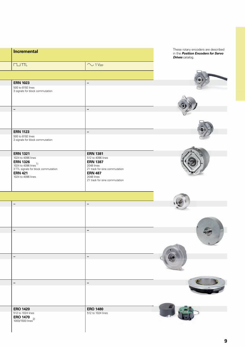
ERN 1023 IP64 – – – – ERN 1023 –500 to 8192 lines3 signals for block commutation
ECN/EQN 1100 series ECN 1123 ECN 1113 EQN 1135 EQN 1125 – –Positions/rev: 23 bitsEnDat 2.2/22Functional safety upon request
Positions/rev: 13 bitsEnDat 2.2/01
Positions/rev: 23 bits4096 revolutionsEnDat 2.2/22Functional safety upon request
Positions/rev: 13 bits4096 revolutionsEnDat 2.2/01
ERN 1123 IP00 – – – – ERN 1123 –500 to 8192 lines3 signals for block commutation
ECN/EQN/ERN 1300 series IP40ECN/EQN/ERN 400 series IP64
ECN 1325 ECN 1313 EQN 1337 EQN 1325 ERN 1321 ERN 1381Positions/rev: 25 bitsEnDat 2.2/22Functional safety upon request
ECN 425Positions/rev: 25 bitsEnDat 2.2/22Functional safety upon request
Positions/rev: 13 bitsEnDat 2.2/01
ECN 413Positions/rev: 13 bitsEnDat 2.2/01
Positions/rev: 25 bits4096 revolutionsEnDat 2.2/22Functional safety upon request
EQN 437Positions/rev: 25 bits4096 revolutionsEnDat 2.2/22Functional safety upon request
Positions/rev: 13 bits4096 revolutionsEnDat 2.2/01
EQN 425Positions/rev: 13 bits4096 revolutionsEnDat 2.2/01
1024 to 4096 lines
ERN 13261024 to 4096 lines
1)
3 TTL signals for block commutation
ERN 4211024 to 4096 lines
512 to 4096 lines
ERN 13872048 linesZ1 track for sine commutation
ERN 4872048 linesZ1 track for sine commutation
Without integral bearing
ECI/EQI/EBI 1100 series ECI 1118 ECI 1118 EBI 1135 EQI 1130 – –Positions/rev: 18 bitsEnDat 2.2/22
Positions/rev: 18 bitsEnDat 2.1/21 or EnDat 2.1/01
Positions/rev: 18 bits65 536 revolutions (battery buffered)EnDat 2.2/22
Positions/rev: 18 bits4096 revolutionsEnDat 2.1/21 or EnDat 2.1/01
ECI/EQI 1300 series – ECI 1319 – EQI 1331 – –Positions/rev: 19 bitsEnDat 2.2/01
Positions/rev: 19 bits4096 revolutionsEnDat 2.2/01
ECI/EQI 1300 series ECI 1319 – EQI 1331 – – –Positions/rev: 19 bitsEnDat 2.2/22Functional safety upon request
Positions/rev: 19 bits4096 revolutionsEnDat 2.2/22Functional safety upon request
ECI/EBI 100 series ECI 119 – EBI 135 – – –Positions/rev: 19 bitsEnDat 2.2/22 or EnDat 2.1/01
Positions/rev: 19 bits65 536 revolutions (battery buffered)EnDat 2.2/22
ERO 1400 series – – – – ERO 1420 ERO 1480512 to 1024 lines
ERO 14701000/1500 lines
2)
512 to 1024 lines
1) 8192 signal periods though integrated 2-fold interpolation 2) Up to 37 500 signal period through integrated 5/10/20/25-fold interpolation
D: 30/38/50 mm
13 for EBI
9
Rotary encoders Absolute Incremental Singleturn Multiturn
Interface EnDat EnDat « TTL » 1 VPP
With integral bearing and mounted stator coupling
ERN 1023 IP64 – – – – ERN 1023 –500 to 8192 lines3 signals for block commutation
ECN/EQN 1100 series ECN 1123 ECN 1113 EQN 1135 EQN 1125 – –Positions/rev: 23 bitsEnDat 2.2/22Functional safety upon request
Positions/rev: 13 bitsEnDat 2.2/01
Positions/rev: 23 bits4096 revolutionsEnDat 2.2/22Functional safety upon request
Positions/rev: 13 bits4096 revolutionsEnDat 2.2/01
ERN 1123 IP00 – – – – ERN 1123 –500 to 8192 lines3 signals for block commutation
ECN/EQN/ERN 1300 series IP40ECN/EQN/ERN 400 series IP64
ECN 1325 ECN 1313 EQN 1337 EQN 1325 ERN 1321 ERN 1381Positions/rev: 25 bitsEnDat 2.2/22Functional safety upon request
ECN 425Positions/rev: 25 bitsEnDat 2.2/22Functional safety upon request
Positions/rev: 13 bitsEnDat 2.2/01
ECN 413Positions/rev: 13 bitsEnDat 2.2/01
Positions/rev: 25 bits4096 revolutionsEnDat 2.2/22Functional safety upon request
EQN 437Positions/rev: 25 bits4096 revolutionsEnDat 2.2/22Functional safety upon request
Positions/rev: 13 bits4096 revolutionsEnDat 2.2/01
EQN 425Positions/rev: 13 bits4096 revolutionsEnDat 2.2/01
1024 to 4096 lines
ERN 13261024 to 4096 lines
1)
3 TTL signals for block commutation
ERN 4211024 to 4096 lines
512 to 4096 lines
ERN 13872048 linesZ1 track for sine commutation
ERN 4872048 linesZ1 track for sine commutation
Without integral bearing
ECI/EQI/EBI 1100 series ECI 1118 ECI 1118 EBI 1135 EQI 1130 – –Positions/rev: 18 bitsEnDat 2.2/22
Positions/rev: 18 bitsEnDat 2.1/21 or EnDat 2.1/01
Positions/rev: 18 bits65 536 revolutions (battery buffered)EnDat 2.2/22
Positions/rev: 18 bits4096 revolutionsEnDat 2.1/21 or EnDat 2.1/01
ECI/EQI 1300 series – ECI 1319 – EQI 1331 – –Positions/rev: 19 bitsEnDat 2.2/01
Positions/rev: 19 bits4096 revolutionsEnDat 2.2/01
ECI/EQI 1300 series ECI 1319 – EQI 1331 – – –Positions/rev: 19 bitsEnDat 2.2/22Functional safety upon request
Positions/rev: 19 bits4096 revolutionsEnDat 2.2/22Functional safety upon request
ECI/EBI 100 series ECI 119 – EBI 135 – – –Positions/rev: 19 bitsEnDat 2.2/22 or EnDat 2.1/01
Positions/rev: 19 bits65 536 revolutions (battery buffered)EnDat 2.2/22
ERO 1400 series – – – – ERO 1420 ERO 1480512 to 1024 lines
ERO 14701000/1500 lines
2)
512 to 1024 lines
1) 8192 signal periods though integrated 2-fold interpolation 2) Up to 37 500 signal period through integrated 5/10/20/25-fold interpolation
These rotary encoders are described in the Position Encoders for Servo Drives catalog.
10
Rotary encoders Absolute Incremental Singleturn Multiturn 4096 revolutions
Interface EnDat SSI EnDat SSI « TTL « HTL » 1 VPP
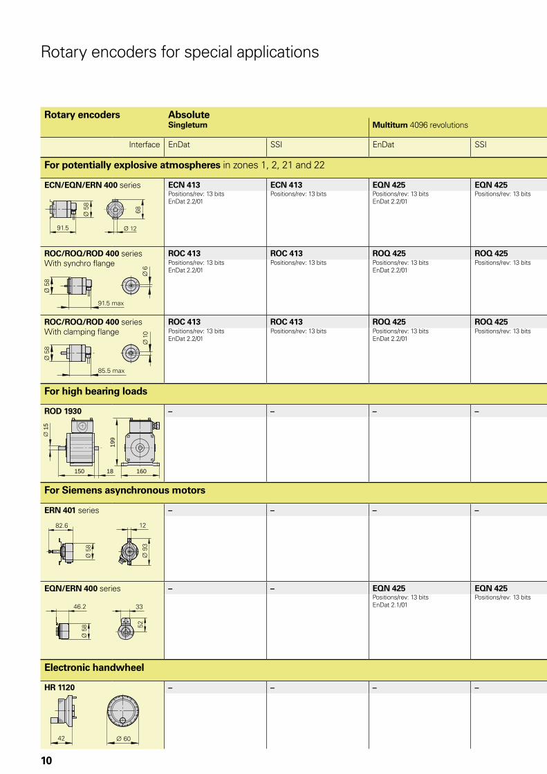
For potentially explosive atmospheres in zones 1, 2, 21 and 22
ECN/EQN/ERN 400 series ECN 413 ECN 413 EQN 425 EQN 425 ERN 420 ERN 430 ERN 480Positions/rev: 13 bitsEnDat 2.2/01
Positions/rev: 13 bits Positions/rev: 13 bitsEnDat 2.2/01
Positions/rev: 13 bits 1000 to 5000 lines 1000 to 5000 lines 1000 to 5000 lines
ROC/ROQ/ROD 400 seriesWith synchro flange
ROC 413 ROC 413 ROQ 425 ROQ 425 ROD 426 ROD 436 ROD 486Positions/rev: 13 bitsEnDat 2.2/01
Positions/rev: 13 bits Positions/rev: 13 bitsEnDat 2.2/01
Positions/rev: 13 bits 1000 to 5000 lines 1000 to 5000 lines 1000 to 5000 lines
ROC/ROQ/ROD 400 seriesWith clamping flange
ROC 413 ROC 413 ROQ 425 ROQ 425 ROD 420 ROD 430 ROD 480 Positions/rev: 13 bitsEnDat 2.2/01
Positions/rev: 13 bits Positions/rev: 13 bitsEnDat 2.2/01
Positions/rev: 13 bits 1000 to 5000 lines 1000 to 5000 lines 1000 to 5000 lines
For high bearing loads
ROD 1930 – – – – – ROD 1930 – 76600 to 2400 lines
For Siemens asynchronous motors
ERN 401 series – – – – ERN 421 ERN 431 – 1024 lines 1024 lines
EQN/ERN 400 series – – EQN 425 EQN 425 ERN 420 ERN 430 – Positions/rev: 13 bitsEnDat 2.1/01
Positions/rev: 13 bits 1024 lines 1024 lines
Electronic handwheel
HR 1120 – – – – HR 1120 – – 78100 lines
Rotary encoders for special applications
150 18
199
160
1
5

11
Rotary encoders Absolute Incremental Singleturn Multiturn 4096 revolutions
Interface EnDat SSI EnDat SSI « TTL « HTL » 1 VPP
For potentially explosive atmospheres in zones 1, 2, 21 and 22
ECN/EQN/ERN 400 series ECN 413 ECN 413 EQN 425 EQN 425 ERN 420 ERN 430 ERN 480Positions/rev: 13 bitsEnDat 2.2/01
Positions/rev: 13 bits Positions/rev: 13 bitsEnDat 2.2/01
Positions/rev: 13 bits 1000 to 5000 lines 1000 to 5000 lines 1000 to 5000 lines
ROC/ROQ/ROD 400 seriesWith synchro flange
ROC 413 ROC 413 ROQ 425 ROQ 425 ROD 426 ROD 436 ROD 486Positions/rev: 13 bitsEnDat 2.2/01
Positions/rev: 13 bits Positions/rev: 13 bitsEnDat 2.2/01
Positions/rev: 13 bits 1000 to 5000 lines 1000 to 5000 lines 1000 to 5000 lines
ROC/ROQ/ROD 400 seriesWith clamping flange
ROC 413 ROC 413 ROQ 425 ROQ 425 ROD 420 ROD 430 ROD 480 Positions/rev: 13 bitsEnDat 2.2/01
Positions/rev: 13 bits Positions/rev: 13 bitsEnDat 2.2/01
Positions/rev: 13 bits 1000 to 5000 lines 1000 to 5000 lines 1000 to 5000 lines
For high bearing loads
ROD 1930 – – – – – ROD 1930 – 76600 to 2400 lines
For Siemens asynchronous motors
ERN 401 series – – – – ERN 421 ERN 431 – 1024 lines 1024 lines
EQN/ERN 400 series – – EQN 425 EQN 425 ERN 420 ERN 430 – Positions/rev: 13 bitsEnDat 2.1/01
Positions/rev: 13 bits 1024 lines 1024 lines
Electronic handwheel
HR 1120 – – – – HR 1120 – – 78100 lines
You will find these rotary encoders in the Product Overview
Rotary Encoders for Potentially Explosive Atmospheres
You will find these rotary encoders in the catalogEncoders for servo drivesEncoders for servo drives
Atmospheres

12
Measuring principlesMeasuring standards Measurement procedure
HEIDENHAIN encoders with optical scan-ning incorporate measuring standards of periodic structures known as graduations. These graduations are applied to a carrier substrate of glass or steel.
These precision graduations are manufac-tured in various photolithographic process-es. Graduations are fabricated from• extremely hard chromium lines on glass• matte-etched lines on gold-plated steel
tape• three-dimensional structures on glass or
steel substrates
The photolithographic manufacturing processes developed by HEIDENHAIN produce grating periods of typically 50 µm to 4 µm.
These processes permit very fine grating periods and are characterized by a high definition and homogeneity of the line edges. Together with the photoelectric scanning method, this high edge definition is a precondition for the high quality of the output signals.
The master graduations are manufactured by HEIDENHAIN on custom-built high-precision dividing engines.
Encoders using the inductive scanning principle work with graduation structures of copper and nickel. The graduation is applied to a carrier material for printed circuits.
With the absolute measuring method, the position value is available from the encoder immediately upon switch-on and can be called at any time by the sub-sequent electronics. There is no need to move the axes to find the reference position. The absolute position information is read from the graduated disk which is formed from a serial absolute code structure.
A separate incremental track is interpolated for the position value and at the same time is used to generate an optional incremental signal.
In singleturn encoders, the absolute position information repeats itself with every revolution. Multiturn encoders can also distinguish between revolutions.
Circular graduations of absolute rotary encoders
With the incremental measuring method, the graduation consists of a periodic grating structure. The position information is obtained by counting the individual increments (measuring steps) from some point of origin. Since an absolute reference is required to ascertain positions, the graduated disks are provided with an additional track that bears a reference mark.
The absolute position established by the reference mark is gated with exactly one measuring step.
The reference mark must therefore be scanned to establish an absolute reference or to find the last selected datum.
Circular graduations of incremental rotary encoders

13
Scanning methods
Photoelectric scanning principleMost HEIDENHAIN encoders operate using the principle of photoelectric scanning. Photoelectric scanning of a measuring standard is contact-free, and as such, free of wear. This method detects even very fine lines, no more than a few micrometers wide, and generates output signals with very small signal periods.
The ECN, EQN, ERN and ROC, ROQ, ROD rotary encoders use the imaging scanning principle.
Put simply, the imaging scanning principle functions by means of projected-light signal generation: two graduations with equal grating periods—the circular scale and the scanning reticle—are moved relative to each other. The carrier material of the scanning reticle is transparent. The graduation on the measuring standard can likewise be applied to a transparent surface, but also a reflective surface.
When parallel light passes through a grating, light and dark surfaces are projected at a certain distance. An index grating with the same grating period is located here. When the two gratings move relative to each oth-er, the incident light is modulated. If the gaps in the gratings are aligned, light passes through. If the lines of one grating coincide with the gaps of the other, no light passes through. Photovoltaic cells convert these variations in light intensity into nearly sinu-soidal electrical signals. Practical mounting tolerances for encoders with the imaging scanning principle are achieved with grating periods of 10 µm and larger.
Photoelectric scanning according to the imaging scanning principle
LED light source
Condenser lens
Scanning reticleMeasuring standard
Photocells
I90° and I270° photocells are not shown
Accuracy
The accuracy of position measurement with rotary encoders is mainly determined by• the directional deviation of the radial
grating• the eccentricity of the graduated disk to
the bearing• the radial runout of the bearing• the error resulting from the connection
with a shaft coupling (on rotary encoders with stator coupling this error lies within the system accuracy)
• the interpolation error during signal processing in the integrated or external interpolation and digitizing electronics
For incremental rotary encoders with line counts up to 5000:The maximum directional deviation at 20 °C ambient temperature and slow speed (scanning frequency between 1 kHz and 2 kHz) lies within
18° mech. · 3600 [angular seconds]
which equals
± 1 grating period.
ROD rotary encoders generate 6000 to 10 000 signal periods per revolution through signal doubling. The line count is important for the system accuracy.
The accuracy of absolute position values from absolute rotary encoders is given in the specifications for each model.
For absolute rotary encoders with complementary incremental signals, the accuracy depends on the line count:
Line count Accuracy 16 ± 280 angular seconds 32 ± 180 angular seconds 512 ± 60 angular seconds2048 ± 20 angular seconds2048 ± 10 angular seconds
(ROC 425 with high accuracy)
The above accuracy data refer to incremen-tal measuring signals at an ambient tem-perature of 20 °C and at slow speed.
Line count z
20
The absolute rotary encoders with optimized scanning have a single large photosensor instead of a group of individual photoelements. Its structures have the same width as that of the measuring standard. This makes it possible to do without the scanning reticle with matching structure.
Other scanning principlesECI/EBI/EQI and RIC/RIQ rotary encoders operate according to the inductive measuring principle. Here, graduation structures modulate a high-frequency signal in its amplitude and phase. The position value is always formed by sampling the signals of all receiver coils distributed evenly around the circumference.

14
Mechanical design types and mountingRotary encoders with stator coupling
ECN/EQN/ERN rotary encoders have integrated bearings and a mounted stator coupling. The stator coupling compensates radial runout and alignment errors without significantly reducing the accuracy. The encoder shaft is directly connected with the shaft to be measured. During angular acceleration of the shaft, the stator coupling must absorb only that torque caused by friction in the bearing. The stator coupling permits axial motion of the measured shaft:
ECN/EQN/ERN 400: ± 1 mm
ECN/EQN/ERN 1000: ± 0.5 mm
ECN/ERN 100: ± 1,5 mm
MountingThe rotary encoder is slid by its hollow shaft onto the measured shaft, and the rotor is fastened by two screws or three eccentric clamps. For rotary encoders with hollow through shaft, the rotor can also be fastened at the end opposite to the flange. Rotary encoders of the ECN/EQN/ERN 1300 series with taper shaft are particularly well suited for repeated mounting (see catalog titled Position Encoders for Servo Drives). The stator is connected without a centering collar on a flat surface. The universal stator coupling of the ECN/EQN/ERN 400 permits versatile mounting, e.g. by its thread provided for fastening it from outside to the motor cover.
L = 41 min. with D 25L = 56 min. with D 38
ECN/EQN/ERN 400 with standard stator coupling
Hollow through shaft
ECN/EQN/ERN 400With universal stator coupling
Hollow through shaft
Grooves visible
Blind hollow shaft
Dynamic applications require the highest possible natural frequencies fN of the system (also see General mechanical information). This is attained by connecting the shafts on the flange side and fastening the coupling by four cap screws or, on the ECN/EQN/ERN 1000, with special washers.
Natural frequency fN with coupling fastened by 4 screws
Stator coupling
Cable Flange socket
Axial Radial
ECN/EQN/ERN 400
StandardUniversal
1550 Hz1400 Hz1)
1500 Hz1400 Hz
1000 Hz 900 Hz
ECN/ERN 100 1000 Hz – 400 Hz
ECN/EQN/ERN 1000 1500 Hz2 – –
1) Also when fastening with 2 screws2) Also when fastening with 2 screws and washers
Washers

15
If the encoder shaft is subject to high loads, for example from friction wheels, pulleys, or sprockets, HEIDENHAIN recommends mounting the ECN/EQN/ERN 400 with a bearing assembly.
Bearing assemblyFor ECN/EQN/ERN 400 with blind hollow shaftID 574185-03
The bearing assembly is capable of absorbing large radial shaft loads. It prevents overload of the encoder bearing. On the encoder side, the bearing assembly has a stub shaft with 12 mm diameter and is well suited for the ECN/EQN/ERN 400 encoders with blind hollow shaft. Also, the threaded holes for fastening the stator coupling are already provided. The flange of the bearing assembly has the same dimensions as the clamping flange of the ROD 420/430 series. The bearing assembly can be fastened through the threaded holes on its face or with the aid of the mounting flange or the mounting bracket (see page 19).
Shaft clamp ringFor ECN/EQN/ERN 400By using a second shaft clamp ring, the mechanically permissible speed of rotary encoders with hollow through shaft can be increased to a maximum of 12 000 rpm.ID 540741-xx
= Clamping screw with X8 hexalobular socket tightening torque 1.1 ± 0.1 Nm
Bearing assembly
Permissible speed n 6000 rpm
Shaft load Axial: 150 N; radial: 350 N
Operating temperature –40 °C to 100 °C
Protection (EN 60 529) IP 64
Mounting accessories
WasherFor ECN/EQN/ERN 1000For increasing the natural frequency fN when mounting with only two screws.ID 334653-01

16
Torque supports for ECN/EQN/ERN 400For simple applications with the ECN/EQN/ERN 400, the stator coupling can be replaced by torque supports. The following kits are available:
Wire torque supportThe stator coupling is replaced by a metal plate to which the provided wire is fastened as coupling.ID 510955-01
Pin torque supportInstead of a stator coupling, a “synchro flange” is fastened to the encoder. A pin serving as torque support is mounted either axially or radially on the flange. As an alternative, the pin can be pressed in on the customer's surface, and a guide can be inserted in the encoder flange for the pin.ID 510861-01
General accessories
Screwdriver bits• For HEIDENHAIN shaft couplings• For ExN 100/400/1000 shaft couplings• For ERO shaft clamping
Width across flats
Length ID
1.5 70 mm 350378-01
1.5 (ball head) 350378-02
2 350378-03
2 (ball head) 350378-04
2.5 350378-05
3 (ball head) 350378-08
4 350378-07
4 (with dog point)1)
350378-14
TX8 89 mm152 mm
350378-11350378-12
TX15 70 mm 756768-42
1) For screws as per DIN 6912 (low head screw with pilot recess)
ScrewdriverAdjustable torque0.2 Nm to 1.2 Nm ID 350379-041 Nm to 5 Nm ID 350379-05
50 000
100 000
150 000
250 000
300 000
350 000
200 000
1 000 2 000 3 000 4 000
100 N 100 N100 N 150 N150 N 150 N150 N 200 N
50 000
100 000
150 000
250 000
300 000
350 000
200 000
1 000 2 000 3 000 4 000
100 N 100 N100 N 150 N150 N 150 N150 N 200 N
17
Rotary encoders for separate shaft coupling
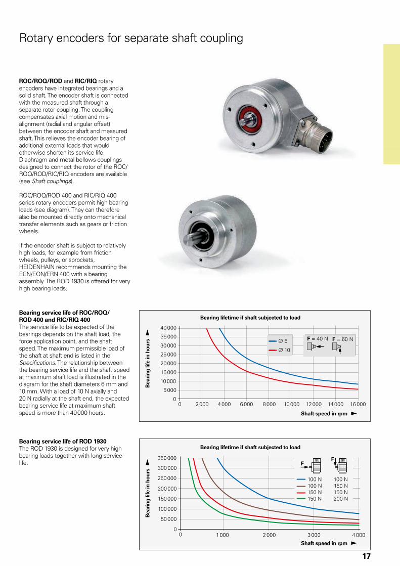
ROC/ROQ/ROD and RIC/RIQ rotary encoders have integrated bearings and a solid shaft. The encoder shaft is connected with the measured shaft through a separate rotor coupling. The coupling compensates axial motion and mis-alignment (radial and angular offset) between the encoder shaft and measured shaft. This relieves the encoder bearing of additional external loads that would otherwise shorten its service life. Diaphragm and metal bellows couplings designed to connect the rotor of the ROC/ROQ/ROD/RIC/RIQ encoders are available (see Shaft couplings).
ROC/ROQ/ROD 400 and RIC/RIQ 400 series rotary encoders permit high bearing loads (see diagram). They can therefore also be mounted directly onto mechanical transfer elements such as gears or friction wheels.
If the encoder shaft is subject to relatively high loads, for example from friction wheels, pulleys, or sprockets, HEIDENHAIN recommends mounting the ECN/EQN/ERN 400 with a bearing assembly. The ROD 1930 is offered for very high bearing loads.
Bearing service life of ROC/ROQ/ROD 400 and RIC/RIQ 400The service life to be expected of the bearings depends on the shaft load, the force application point, and the shaft speed. The maximum permissible load of the shaft at shaft end is listed in the Specifications. The relationship between the bearing service life and the shaft speed at maximum shaft load is illustrated in the diagram for the shaft diameters 6 mm and 10 mm. With a load of 10 N axially and 20 N radially at the shaft end, the expected bearing service life at maximum shaft speed is more than 40 000 hours.
Bea
rin
g li
fe in
ho
urs
Bearing lifetime if shaft subjected to load
Bearing service life of ROD 1930The ROD 1930 is designed for very high bearing loads together with long service life.
Shaft speed in rpm
Shaft speed in rpm
Bea
rin
g li
fe in
ho
urs
Bearing lifetime if shaft subjected to load

18
Mounting accessories
Adapter flange(electrically nonconducting)ID 257044-01
Fixing clampsFor ROC/ROQ/ROD 400 and RIC/RIQ 400 series(3 per encoder)ID 200032-01
Fixing clampsFor ROC/ROQ/ROD 1000 series(3 per encoder)ID 200032-02
Rotary encoders with synchro flange
Mounting• By the synchro flange with three fixing
clamps, or• by fastening threaded holes on the
encoder flange to an adapter flange (for ROC/ROQ/ROD 400 or RIC/RIQ 400)
Mechanical fault exclusion is possible after consultation with HEIDENHAIN in Traunreut, Germany.
Rotary encoders with synchro flange
Fixing clamps
Coupling
Coupling
Adapter flange

19
Mounting accessories
Mounting flangeID 201437-01
Mounting bracketID 581296-01
ROC/ROQ/ROD 400 with clamping flange
Coupling
Coupling
Mounting flange
Rotary encoders with clamping flange
Mounting• By fastening the threaded holes on the
encoder flange to an adapter flange or• by clamping at the clamping flange
or• for encoders with additional slot, by the
clamping flange with three fixing clamps
The centering collar on the synchro flange or clamping flange serves to center the encoder.
Mechanical fault exclusion is possible after consultation with HEIDENHAIN in Traunreut, Germany.

20
Rotary encoder mounted by flange/base
Mounting• By flange, or• on baseThe encoder is fastened by four M8 screws.
The terminal box can be mounted in 90° offsets.
Shaft couplingThe encoder shaft features a feather key for optimum torque transmission. The couplings C19 and C 212 provided as accessories feature an appropriate holder.

21
Shaft couplings
ROC/ROQ/ROD 400 ROD 1930 ROC/ROQ/ROD 1000
Diaphragm coupling Diaphragm coupling Metal bellows coupling
K 14 K 17/01K 17/06
K 17/02K 17/04K 17/05
K 17/03 C 19 C 212 18EBN3
Hub bore 6/6 mm 6/6 mm 6/5 mm
6/10 mm10/10 mm6/9.52 mm
10/10 mm 15/15 4/4 mm
Galvanic isolation – � � � – � –
Kinematic transfer error*
± 6” ± 10” ± 13” ± 40”
Torsional rigidity
500 Nm 150 Nm 200 Nm 300 Nm 1700 Nm 60 Nm
Torque 0.2 Nm 0.1 Nm 0.2 Nm 3.9 Nm 5 Nm 0.1 Nm
Radial offset l 0.2 mm 0.5 mm 0.3 mm 0.2 mm
Angular error a 0.5° 1° 1.5° 0.5°
Axial motion d 0.3 mm 0.5 mm 1.7 mm 0.3 mm
Moment of inertia (approx.)
6 · 10-6 kgm2 3 · 10-6 kgm2 4 · 10-6 kgm2 15 · 10-6 kgm2 0.3 · 10-6 kgm2
Permissible speed 16 000 rpm 20 000 rpm 6000 rpm 12 000 rpm
Torque for locking screws (approx.)
1.2 Nm 1.37 Nm 0.8 Nm
Mass 35 g 24 g 23 g 27.5 g 75 g 9 g
*With radial offset l = 0.1 mm, angular error a = 0.15 mm over 100 mm 0.09° up to 50 °C
rad rad rad rad rad
Axial motionAngular errorRadial offset
Mounting accessories
Screwdriver bitsScrewdriverSee page 16
rad

22
Metal bellows coupling 18 EBN 3For ROC/ROQ/ROD 1000 series rotary encodersWith 4 mm shaft diameterID 200393-02
Diaphragm coupling K 14For ROC/ROQ/ROD 400 and RIC/RIQ 400 seriesWith 6 mm shaft diameterID 293328-01
Diaphragm coupling K 17 with galvanic isolationFor ROC/ROQ/ROD 400 and RIC/RIQ 400 seriesWith 6 or 10 mm shaft diameterID 296746-xx
Recommended fit for the mating shaft: h6
K 17Variant
D1 D2 L
01 ¬ 6 F7 ¬ 6 F7 22 mm
02 ¬ 6 F7 ¬ 10 F7 22 mm
03 ¬ 10 F7 ¬ 10 F7 30 mm
04 ¬ 10 F7 ¬ 10 F7 22 mm
05 ¬ 6 F7 ¬ 9.52 F7 22 mm
06 ¬ 5 F7 ¬ 6 F7 22 mm
Suitable also for potentially explosive atmospheres in zones 1, 2, 21 and 22

23
C 19 diaphragm couplingFor ROD 1930 rotary encoder with 15 mm shaft diameter and feather keyID 731374-01
C 212 diaphragm couplingWith galvanic isolation For ROD 1930 rotary encoder with 15 mm shaft diameter and feather keyID 731374-02

24
The term functional safety designates HEIDENHAIN encoders that can be used in safety-related applications. These encoders operate as single-encoder systems with purely serial data transmission via EnDat 2.2. Reliable transmission of the position is based on two independently generated absolute position values and on error bits, which are then provided to the safe control.
Basic principleHEIDENHAIN measuring systems for safety-related applications are tested for compliance with EN ISO 13 849-1 (successor to EN 954-1) as well as EN 61 508 and EN 61 800-5-2. These standards describe the assessment of safety-oriented systems, for example based on the failure probabilities of integrated components and subsystems. This modular approach helps manu-facturers of safety-oriented systems to implement their complete systems, because they can begin with subsystems that have already been qualified. Safety-related position measuring systems with purely serial data transmission via EnDat 2.2 accommodate this technique. In a safe drive, the safety-related position measuring system is such a subsystem. A safety-related position measuring system consists of:• Encoder with EnDat 2.2 transmission
component• Data transfer line with EnDat 2.2
communication and HEIDENHAIN cable• EnDat 2.2 receiver component with
monitoring function (EnDat master)
In practice, the complete “safe servo drive” system consists of:• Safety-related position measuring
system• Safety-related control (including EnDat
master with monitoring functions)• Power stage with motor power cable
and drive• Mechanical connection between
encoder and drive (e.g. rotor/stator connection)
Safety-related position encoders
Field of applicationSafety-related position measuring systems from HEIDENHAIN are designed so that they can be used as single-encoder systems in applications with control category SIL 2 (according to EN 61 508), performance level “d”, category 3 (according to EN ISO 13 849).
Additional measures in the control make it possible to use certain encoders for appli-cations up to SIL 3, PL “e”, category 4. The suitability of these encoders is indicated appropriately in the documentation (catalogs / product information sheets).
The functions of the safety-related position measuring system can be used for the following safety tasks in the complete system (also see EN 61 800-5-2):
Complete safe drive system
Safety-related position measuring system
EnDat master
Encoder
Power cables
Safe controlDrive motor
Power stage
SS1 Safe Stop 1 Safe stop 1
SS2 Safe Stop 2 Safe stop 2
SOS Safe Operating Stop Safe operating stop
SLA Safely Limited Acceleration
Safely limited acceleration
SAR Safe Acceleration Range Safe acceleration range
SLS Safely Limited Speed Safely limited speed
SSR Safe Speed Range Safe speed range
SLP Safely Limited Position Safely limited position
SLI Safely Limited Increment Safely limited increment
SDI Safe Direction Safe direction
SSM Safe Speed Monitor Safe report of the limited speed
Safety functions according to EN 61 800-5-2
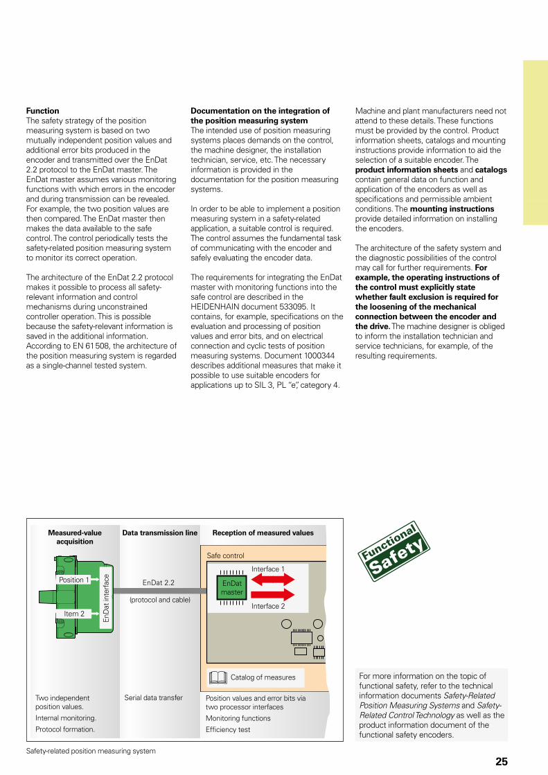
25Safety-related position measuring system
Measured-value acquisition
Data transmission line
Position values and error bits via two processor interfaces
Monitoring functions
Efficiency test
Reception of measured values
Position 1
Item 2
(protocol and cable)
Serial data transferTwo independent position values.
Internal monitoring.
Protocol formation.
EnD
at in
terf
ace
EnDat master
Interface 1
Interface 2
Safe control
Catalog of measures For more information on the topic of functional safety, refer to the technical information documents Safety-Related Position Measuring Systems and Safety-Related Control Technology as well as the product information document of the functional safety encoders.
FunctionThe safety strategy of the position measuring system is based on two mutually independent position values and additional error bits produced in the encoder and transmitted over the EnDat 2.2 protocol to the EnDat master. The EnDat master assumes various monitoring functions with which errors in the encoder and during transmission can be revealed. For example, the two position values are then compared. The EnDat master then makes the data available to the safe control. The control periodically tests the safety-related position measuring system to monitor its correct operation.
The architecture of the EnDat 2.2 protocol makes it possible to process all safety-relevant information and control mechanisms during unconstrained controller operation. This is possible because the safety-relevant information is saved in the additional information. According to EN 61 508, the architecture of the position measuring system is regarded as a single-channel tested system.
Documentation on the integration of the position measuring systemThe intended use of position measuring systems places demands on the control, the machine designer, the installation technician, service, etc. The necessary information is provided in the documentation for the position measuring systems.
In order to be able to implement a position measuring system in a safety-related application, a suitable control is required. The control assumes the fundamental task of communicating with the encoder and safely evaluating the encoder data.
The requirements for integrating the EnDat master with monitoring functions into the safe control are described in the HEIDENHAIN document 533095. It contains, for example, specifications on the evaluation and processing of position values and error bits, and on electrical connection and cyclic tests of position measuring systems. Document 1000344 describes additional measures that make it possible to use suitable encoders for applications up to SIL 3, PL “e”, category 4.
Machine and plant manufacturers need not attend to these details. These functions must be provided by the control. Product information sheets, catalogs and mounting instructions provide information to aid the selection of a suitable encoder. The product information sheets and catalogs contain general data on function and application of the encoders as well as specifications and permissible ambient conditions. The mounting instructions provide detailed information on installing the encoders.
The architecture of the safety system and the diagnostic possibilities of the control may call for further requirements. For example, the operating instructions of the control must explicitly state whether fault exclusion is required for the loosening of the mechanical connection between the encoder and the drive. The machine designer is obliged to inform the installation technician and service technicians, for example, of the resulting requirements.
26
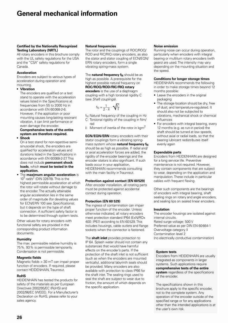
General mechanical information
Certified by the Nationally Recognized Testing Laboratory (NRTL)All rotary encoders in this brochure comply with the UL safety regulations for the USA and the “CSA” safety regulations for Canada.
AccelerationEncoders are subject to various types of acceleration during operation and mounting.• Vibration
The encoders are qualified on a test stand to operate with the acceleration values listed in the Specifications at frequencies from 55 to 2000 Hz in accordance with EN 60 068-2-6. However, if the application or poor mounting causes long-lasting resonant vibration, it can limit performance or even damage the encoder. Comprehensive tests of the entire system are therefore required.
• Shock On a test stand for non-repetitive semi-sinusoidal shock, the encoders are qualified for acceleration values and durations listed in the Specifications in accordance with EN 60068-2-27. This does not include permanent shock loads, which must be tested in the application.
• The maximum angular acceleration is 105 rad/s2 (DIN 32878). This is the highest permissible acceleration at which the rotor will rotate without damage to the encoder. The actually attainable angular acceleration lies in the same order of magnitude (for deviating values for ECN/ERN 100 see Specifications), but it depends on the type of shaft connection. A sufficient safety factor is to be determined through system tests.
Other values for rotary encoders with functional safety are provided in the corresponding product information documents.
HumidityThe max. permissible relative humidity is 75 %. 93 % is permissible temporarily. Condensation is not permissible.
Magnetic fieldsMagnetic fields > 30 mT can impair proper function of encoders. If required, please contact HEIDENHAIN, Traunreut.
RoHSHEIDENHAIN has tested the products for safety of the materials as per European Directives 2002/95/EC (RoHS) and 2002/96/EC (WEEE). For a Manufacturer’s Declaration on RoHS, please refer to your sales agency.
Natural frequenciesThe rotor and the couplings of ROC/ROQ/ROD and RIC/RIQ rotary encoders, as also the stator and stator coupling of ECN/EQN/ERN rotary encoders, form a single vibrating spring-mass system.
The natural frequency fN should be as high as possible. A prerequisite for the highest possible natural frequency on ROC/ROQ/ROD/RIC/RIQ rotary encoders is the use of a diaphragm coupling with a high torsional rigidity C (see Shaft couplings).
fN = 2 · þ
· ¹C1I
fN: Natural frequency of the coupling in HzC: Torsional rigidity of the coupling in Nm/
radI: Moment of inertia of the rotor in kgm2
ECN/EQN/ERN rotary encoders with their stator couplings form a vibrating spring-mass system whose natural frequency fN should be as high as possible. If radial and/or axial acceleration forces are added, the rigidity of the encoder bearings and the encoder stators is also significant. If such loads occur in your application, HEIDENHAIN recommends consulting with the main facility in Traunreut.
Protection against contact (EN 60 529)After encoder installation, all rotating parts must be protected against accidental contact during operation.
Protection (EN 60 529)The ingress of contamination can impair proper function of the encoder. Unless otherwise indicated, all rotary encoders meet protection standard IP64 (ExN/ROx 400: IP67) according to EN 60 529. This includes housings, cable outlets and flange sockets when the connector is fastened.
The shaft inlet provides protection to IP 64. Splash water should not contain any substances that would have harmful effects on the encoder’s parts. If the protection of the shaft inlet is not sufficient (such as when the encoders are mounted vertically), additional labyrinth seals should be provided. Many encoders are also available with protection to class IP66 for the shaft inlet. The sealing rings used to seal the shaft are subject to wear due to friction, the amount of which depends on the specific application.
Noise emissionRunning noise can occur during operation, particularly when encoders with integral bearing or multiturn rotary encoders (with gears) are used. The intensity may vary depending on the mounting situation and the speed.
Conditions for longer storage timesHEIDENHAIN recommends the following in order to make storage times beyond 12 months possible:• Leave the encoders in the original
packaging• The storage location should be dry, free
of dust, and temperature-regulated. It should also not be subjected to vibrations, mechanical shock or chemical influences
• For encoders with integral bearing, every 12 months (e.g. as run-in period) the shaft should be turned at low speeds, without axial or radial loads, so that the bearing lubricant redistributes itself evenly again
Expendable partsEncoders from HEIDENHAIN are designed for a long service life. Preventive maintenance is not required. However, they contain components that are subject to wear, depending on the application and manipulation. These include in particular cables with frequent flexing.
Other such components are the bearings of encoders with integral bearing, shaft sealing rings on rotary and angle encoders, and sealing lips on sealed linear encoders.
InsulationThe encoder housings are isolated against internal circuits.Rated surge voltage: 500 VPreferred value as per DIN EN 60 664-1Overvoltage category IIContamination level 2(no electrically conductive contamination)
System testsEncoders from HEIDENHAIN are usually integrated as components in larger systems. Such applications require comprehensive tests of the entire system regardless of the specifications of the encoder.
The specifications shown in this brochure apply to the specific encoder, not to the complete system. Any operation of the encoder outside of the specified range or for any applications other than the intended applications is at the user’s own risk.

27
Temperature rangesFor the unit in its packaging, the storage temperature range is –30 °C to 65 °C (HR 1120: –30 °C to 70 °C). The operating temperature range indicates the temperatures that the encoder may reach during operation in the actual installation environment. The function of the encoder is guaranteed within this range (DIN 32 878). The operating temperature is measured on the defined encoder (see dimension drawing) and must not be confused with the ambient temperature.
The temperature of the encoder is influenced by:• Mounting conditions• The ambient temperature• Self-heating of the encoder
The self-heating of an encoder depends both on its design characteristics (stator coupling/solid shaft, shaft sealing ring, etc.) and on the operating parameters (rotational speed, voltage supply). Temporarily in-creased self-heating can also occur after very long breaks in operation (of several months). Please take a two-minute run-in period at low speeds into account. Higher heat generation in the encoder means that a lower ambient temperature is required to keep the encoder within its permissible operating temperature range.
These tables show the approximate values of self-heating to be expected in the encoders. In the worst case, a combination of operating parameters can exacerbate self-heating, for example a 30 V voltage supply and maximum rotational speed. Therefore, the actual operating tem-perature should be measured directly at the encoder if the encoder is operated near the limits of permissible parameters. Then suitable measures should be taken (fan, heat sinks, etc.) to reduce the ambient temperature far enough so that the maximum permissible operating temperature will not be exceeded during continuous operation.
For high speeds at maximum permissible ambient temperature, special versions are available on request with reduced degree of protection (without shaft seal and its concomitant frictional heat).
Heat generation at speed nmax
Stub shaft/tapered shaftROC/ROQ/ROD/ RIC/RIQ/ ExN 400/1300
≈ + 5 K≈ + 10 K for IP 66 protection
Blind hollow shaftECN/EQN/ ERN 400/1300
≈ + 30 K≈ + 40 K for IP 66 protection
ECN/EQN/ ERN 1000
≈ + 10 K
Hollow through shaftECN/ERN 100ECN/EQN/ERN 400
≈ + 40 K with IP 64 protection≈ + 50 K for IP 66 protection
An encoder’s typical self-heating values depend on its design characteristics at maximum permissible speed. The correlation between rotational speed and heat generation is nearly linear.
Measuring the actual operating temperature at the defined measuring point of the rotary encoder (see Specifications)
MountingWork steps to be performed and dimensions to be maintained during mounting are specified solely in the mounting instructions supplied with the unit. All data in this catalog regarding mounting are therefore provisional and not binding; they do not become terms of a contract.
Rotary encoders with functional safety Mounting screws and central screws from HEIDENHAIN (not included in delivery) feature a coating which, after hardening, provides a materially bonding anti-rotation lock. Therefore the screws cannot be reused. The minimum shelf life is 2 years (storage at 30 °C and 65 % relative humidity). The expiration date is printed on the package.
Screw insertion and application of tightening torque must take no longer than five minutes. The required adhesive strength is attained after about six hours at room temperature. The curing time decreases with decreasing temperature. Hardening temperatures below 5 °C are not permissible.
Screws with materially bonding anti-rotation lock must not be used more than once. In case of replacement, recut the threads and use new screws. A chamfer is required on threaded holes to prevent any scraping off of the adhesive layer.
Changes to the encoderThe correct operation and accuracy of encoders from HEIDENHAIN is ensured only if they have not been modified. Any changes, even minor ones, can impair the operation and reliability of the encoders, and result in a loss of warranty. This also includes the use of additional retaining compounds, lubricants (e.g. for screws) or adhesives not explicitly prescribed. In case of doubt, we recommend contacting HEIDENHAIN in Traunreut.
28
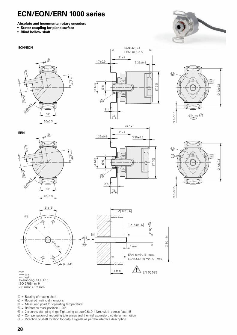
ECN/EQN/ERN 1000 seriesAbsolute and incremental rotary encoders• Stator coupling for plane surface• Blind hollow shaft
A = Bearing of mating shaftk = Required mating dimensionsm = Measuring point for operating temperaturer = Reference mark position ± 20° = 2 x screw clamping rings. Tightening torque 0.6±0.1 Nm, width across flats 1.5 = Compensation of mounting tolerances and thermal expansion, no dynamic motion = Direction of shaft rotation for output signals as per the interface description
29
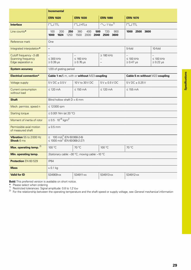
Incremental
ERN 1020 ERN 1030 ERN 1080 ERN 1070
Interface « TTL « HTLs » 1 VPP1) « TTL
Line counts* 100 200 250 360 400 500 720 9001000 1024 1250 1500 2000 2048 2500 3600
1000 2500 3600
Reference mark One
Integrated interpolation* – 5-fold 10-fold
Cutoff frequency –3 dBScanning frequencyEdge separation a
– 300 kHz 0.39 µs
– 160 kHz 0.76 µs
180 kHz––
– 100 kHz 0.47 µs
– 100 kHz 0.22 µs
System accuracy 1/20 of grating period
Electrical connection* Cable 1 m/5 m, with or without M23 coupling Cable 5 m without M23 coupling
Voltage supply 5 V DC ± 0.5 V 10 V to 30 V DC 5 V ± 0.5 V DC 5 V DC ± 0.25 V
Current consumption without load
120 mA 150 mA 120 mA 155 mA
Shaft Blind hollow shaft D = 6 mm
Mech. permiss. speed n 12 000 rpm
Starting torque 0.001 Nm (at 20 °C)
Moment of inertia of rotor 0.5 · 10–6 kgm2
Permissible axial motion of measured shaft
± 0.5 mm
Vibration 55 to 2 000 HzShock 6 ms
100 m/s2 (EN 60 068-2-6) 1000 m/s2 (EN 60 068-2-27)
Max. operating temp. 2) 100 °C 70 °C 100 °C 70 °C
Min. operating temp. Stationary cable: –30 °C; moving cable: –10 °C
Protection EN 60 529 IP64
Mass ≈ 0.1 kg
Valid for ID 534909-xx 534911-xx 534913-xx 534912-xx
Bold: This preferred version is available on short notice.* Please select when ordering1) Restricted tolerances: Signal amplitude: 0.8 to 1.2 VPP2) For the relationship between the operating temperature and the shaft speed or supply voltage, see General mechanical information
Sp
ecifi
cati
on
s

30
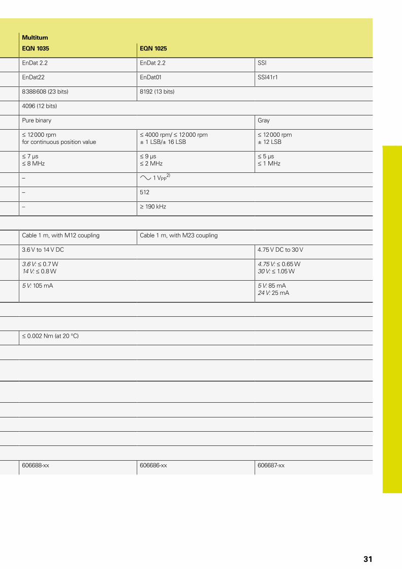
Absolute
Singleturn Multiturn
ECN 1023 ECN 1013 EQN 1035 EQN 1025
Interface EnDat 2.2 EnDat 2.2 SSI EnDat 2.2 EnDat 2.2 SSI
Ordering designation EnDat22 EnDat01 SSI39r1 EnDat22 EnDat01 SSI41r1
Positions per revolution 8 388 608 (23 bits) 8192 (13 bits) 8 388 608 (23 bits) 8192 (13 bits)
Revolutions – 4096 (12 bits)
Code Pure binary Gray Pure binary Gray
Elec. permissible speedDeviations1)
12 000 rpmfor continuous position value
4000 rpm/ 12 000 rpm± 1 LSB/± 16 LSB
12 000 rpm± 12 LSB
12 000 rpmfor continuous position value
4000 rpm/ 12 000 rpm± 1 LSB/± 16 LSB
12 000 rpm± 12 LSB
Calculation time tcalClock frequency
7 µs 8 MHz
9 µs 2 MHz
5 µs 1 MHz
7 µs 8 MHz
9 µs 2 MHz
5 µs 1 MHz
Incremental signals – » 1 VPP2) – » 1 VPP
2)
Line count – 512 – 512
Cutoff frequency –3 dB – 190 kHz – 190 kHz
System accuracy ± 60”
Electrical connection Cable 1 m, with M12 coupling Cable 1 m, with M23 coupling Cable 1 m, with M12 coupling Cable 1 m, with M23 coupling
Voltage supply 3.6 V to 14 V DC 4.75 V DC to 30 V 3.6 V to 14 V DC 4.75 V DC to 30 V
Power consumption (maximum)
3.6 V: 0.6 W14 V: 0.7 W
4.75 V: 0.53 W30 V: 0.86 W
3.6 V: 0.7 W14 V: 0.8 W
4.75 V: 0.65 W30 V: 1.05 W
Current consumption (typical; without load)
5 V: 85 mA 5 V: 70 mA24 V: 20 mA
5 V: 105 mA 5 V: 85 mA24 V: 25 mA
Shaft Blind hollow shaft ¬ 6 mm
Mech. permiss. speed n 12 000 rpm
Starting torque 0.001 Nm (at 20 °C) 0.002 Nm (at 20 °C)
Moment of inertia of rotor ≈ 0.5 · 10–6 kgm2
Permissible axial motion of measured shaft
± 0.5 mm
Vibration 55 to 2000 HzShock 6 ms
100 m/s2 (EN 60 068-2-6) 1000 m/s2 (EN 60 068-2-27)
Max. operating temp. 100 °C
Min. operating temp. Stationary cable: –30 °C; moving cable: –10 °C
Protection EN 60 529 IP64
Mass ≈ 0.1 kg
Valid for ID 606683-xx 606681-xx 606682-xx 606688-xx 606686-xx 606687-xx
1) Velocity-dependent deviations between the absolute and incremental signals2) Restricted tolerances: Signal amplitude 0.80 to 1.2 VPP
31
Absolute
Singleturn Multiturn
ECN 1023 ECN 1013 EQN 1035 EQN 1025
Interface EnDat 2.2 EnDat 2.2 SSI EnDat 2.2 EnDat 2.2 SSI
Ordering designation EnDat22 EnDat01 SSI39r1 EnDat22 EnDat01 SSI41r1
Positions per revolution 8 388 608 (23 bits) 8192 (13 bits) 8 388 608 (23 bits) 8192 (13 bits)
Revolutions – 4096 (12 bits)
Code Pure binary Gray Pure binary Gray
Elec. permissible speedDeviations1)
12 000 rpmfor continuous position value
4000 rpm/ 12 000 rpm± 1 LSB/± 16 LSB
12 000 rpm± 12 LSB
12 000 rpmfor continuous position value
4000 rpm/ 12 000 rpm± 1 LSB/± 16 LSB
12 000 rpm± 12 LSB
Calculation time tcalClock frequency
7 µs 8 MHz
9 µs 2 MHz
5 µs 1 MHz
7 µs 8 MHz
9 µs 2 MHz
5 µs 1 MHz
Incremental signals – » 1 VPP2) – » 1 VPP
2)
Line count – 512 – 512
Cutoff frequency –3 dB – 190 kHz – 190 kHz
System accuracy ± 60”
Electrical connection Cable 1 m, with M12 coupling Cable 1 m, with M23 coupling Cable 1 m, with M12 coupling Cable 1 m, with M23 coupling
Voltage supply 3.6 V to 14 V DC 4.75 V DC to 30 V 3.6 V to 14 V DC 4.75 V DC to 30 V
Power consumption (maximum)
3.6 V: 0.6 W14 V: 0.7 W
4.75 V: 0.53 W30 V: 0.86 W
3.6 V: 0.7 W14 V: 0.8 W
4.75 V: 0.65 W30 V: 1.05 W
Current consumption (typical; without load)
5 V: 85 mA 5 V: 70 mA24 V: 20 mA
5 V: 105 mA 5 V: 85 mA24 V: 25 mA
Shaft Blind hollow shaft ¬ 6 mm
Mech. permiss. speed n 12 000 rpm
Starting torque 0.001 Nm (at 20 °C) 0.002 Nm (at 20 °C)
Moment of inertia of rotor ≈ 0.5 · 10–6 kgm2
Permissible axial motion of measured shaft
± 0.5 mm
Vibration 55 to 2000 HzShock 6 ms
100 m/s2 (EN 60 068-2-6) 1000 m/s2 (EN 60 068-2-27)
Max. operating temp. 100 °C
Min. operating temp. Stationary cable: –30 °C; moving cable: –10 °C
Protection EN 60 529 IP64
Mass ≈ 0.1 kg
Valid for ID 606683-xx 606681-xx 606682-xx 606688-xx 606686-xx 606687-xx
1) Velocity-dependent deviations between the absolute and incremental signals2) Restricted tolerances: Signal amplitude 0.80 to 1.2 VPP

32
ECN/EQN/ERN 400 seriesAbsolute and incremental rotary encoders• Stator coupling for plane surface• Blind hollow shaft or hollow through shaft
Blind hollow shaft
Hollow through shaft
Cable radial, also usable axiallyA = Bearing of mating shaftk = Required mating dimensionsm = Measuring point for operating temperature = Clamping screw with X8 hexalobular socket = Compensation of mounting tolerances and thermal expansion, no dynamic motion permitted = Direction of shaft rotation for output signals as per the interface description1 = Clamping ring on housing side (condition upon delivery)2 = Clamping ring on coupling side (optionally mountable)
Connector codingA = Axial, R = Radial
Flange socket

33
Incremental
ERN 420 ERN 460 ERN 430 ERN 480
Interface « TTL « HTL » 1 VPP1)
Line counts* 250 500 –
1000 1024 1250 2000 2048 2500 3600 4096 5000
Reference mark One
Cutoff frequency –3 dBOutput frequencyEdge separation a
– 300 kHz 0.39 µs
180 kHz––
System accuracy 1/20 of grating period
Electrical connection* • M23 flange socket, radial and axial (with blind hollow shaft)• Cable 1 m, without connecting element
Voltage supply 5 V DC ± 0.5 V 10 V to 30 V DC 10 V to 30 V DC 5 V ± 0.5 V DC
Current consumption without load
120 mA 100 mA 150 mA 120 mA
Shaft* Blind hollow shaft or hollow through shaft; D = 8 mm or D = 12 mm
Mech. permissible speed n2) 6000 rpm/ 12 000 rpm 3)
Starting torque
At 20 °C
Below –20 °C
Blind hollow shaft: 0.01 NmHollow through shaft: 0.025 Nm (for IP66: 0.075 Nm) 1 Nm
Moment of inertia of rotor 4.3 · 10–6 kgm2
Permissible axial motion of measured shaft
± 1 mm
Vibration 55 to 2000 HzShock 6 ms
300 m/s2; Flange socket version: 150 m/s2 (EN 60 068-2-6); higher values upon request 1000 m/s2 (EN 60 068-2-27)
Max. operating temp. 2) 100 °C 70 °C 100 °C4)
Min. operating temp. Flange socket or fixed cable: –40 °C; moving cable: –10 °C
Protection EN 60 529 At housing: IP67 (IP66 for hollow through shaft)At shaft inlet: IP64 (with D = 12 mm, IP66 available on request)
Mass ≈ 0.3 kg
Valid for ID 385420-xx 385460-xx 385430-xx 385480-xx
Bold: This preferred version is available on short notice.* Please select when ordering1) Restricted tolerances: Signal amplitude 0.8 to 1.2 VPP2) For the relationship between the operating temperature and the shaft speed or supply voltage, see General Mechanical Information3) With two shaft clamps (only for hollow through shaft)4) 80° for ERN 480 with 4096 or 5000 lines
34
Absolute
Singleturn Multiturn
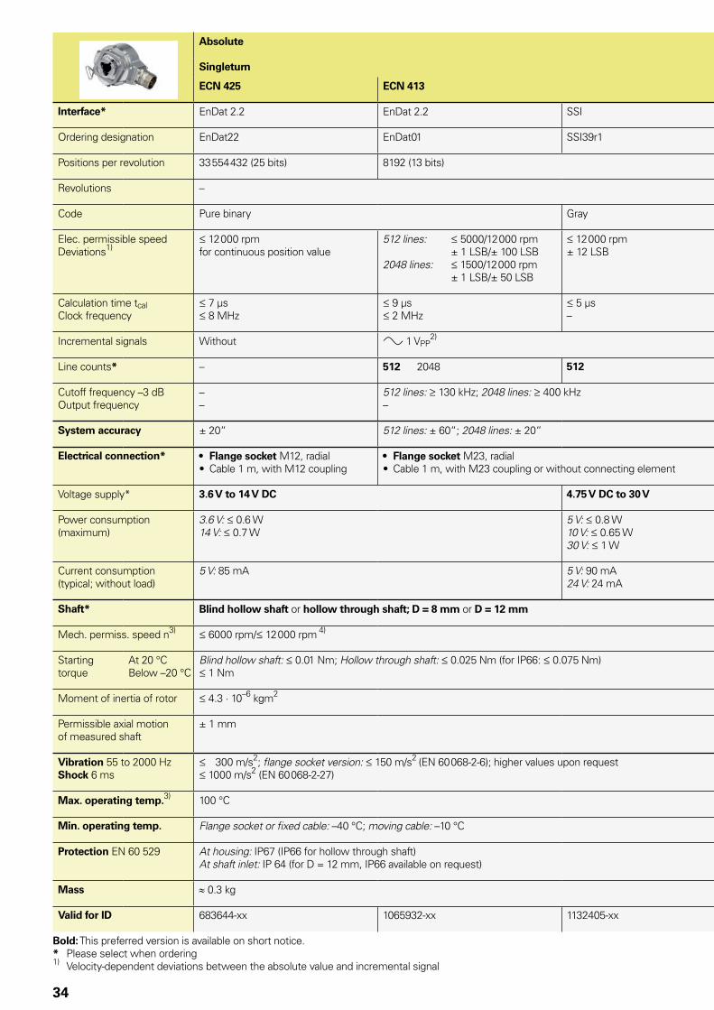
ECN 425 ECN 413 EQN 437 EQN 425
Interface* EnDat 2.2 EnDat 2.2 SSI EnDat 2.2 EnDat 2.2 SSI
Ordering designation EnDat22 EnDat01 SSI39r1 EnDat22 EnDat01 SSI41r1
Positions per revolution 33 554 432 (25 bits) 8192 (13 bits) 33 554 432 (25 bits) 8192 (13 bits)
Revolutions – 4096
Code Pure binary Gray Pure binary Gray
Elec. permissible speedDeviations1)
12 000 rpm for continuous position value
512 lines: 5000/12 000 rpm
± 1 LSB/± 100 LSB2048 lines: 1500/12 000 rpm
± 1 LSB/± 50 LSB
12 000 rpm± 12 LSB
12 000 rpmfor continuous position value
512 lines: 5000/10 000 rpm
± 1 LSB/± 100 LSB2048 lines: 1500/10 000 rpm
± 1 LSB/± 50 LSB
12 000 rpm± 12 LSB
Calculation time tcalClock frequency
7 µs 8 MHz
9 µs 2 MHz
5 µs–
7 µs 8 MHz
9 µs 2 MHz
5 µs–
Incremental signals Without » 1 VPP2) Without » 1 VPP
2)
Line counts* – 512 2048 512 – 512 2048 512
Cutoff frequency –3 dBOutput frequency
––
512 lines: 130 kHz; 2048 lines: 400 kHz–
––
512 lines: 130 kHz; 2048 lines: 400 kHz–
System accuracy ± 20“ 512 lines: ± 60“; 2048 lines: ± 20“ ± 20“ 512 lines: ± 60“; 2048 lines: ± 20“
Electrical connection* • Flange socket M12, radial• Cable 1 m, with M12 coupling
• Flange socket M23, radial• Cable 1 m, with M23 coupling or without connecting element
• Flange socket M12, radial• Cable 1 m, with M12 coupling
• Flange socket M23, radial• Cable 1 m, with M23 coupling or without connecting element
Voltage supply* 3.6 V to 14 V DC 4.75 V DC to 30 V 3.6 V to 14 V DC 3.6 V to 14 V DC 4.75 V DC to 30 V
Power consumption (maximum)
3.6 V: 0.6 W14 V: 0.7 W
5 V: 0.8 W10 V: 0.65 W30 V: 1 W
3.6 V: 0.7 W14 V: 0.8 W
5 V: 0.95 W10 V: 0.75 W30 V: 1.1 W
Current consumption (typical; without load)
5 V: 85 mA 5 V: 90 mA24 V: 24 mA
5 V: 105 mA 5 V: 120 mA24 V: 28 mA
Shaft* Blind hollow shaft or hollow through shaft; D = 8 mm or D = 12 mm
Mech. permiss. speed n3) 6000 rpm/ 12 000 rpm 4)
Starting torque
At 20 °CBelow –20 °C
Blind hollow shaft: 0.01 Nm; Hollow through shaft: 0.025 Nm (for IP66: 0.075 Nm) 1 Nm
Moment of inertia of rotor 4.3 · 10–6 kgm2
Permissible axial motion of measured shaft
± 1 mm
Vibration 55 to 2000 HzShock 6 ms
300 m/s2; flange socket version: 150 m/s2 (EN 60 068-2-6); higher values upon request 1000 m/s2 (EN 60 068-2-27)
Max. operating temp.3) 100 °C
Min. operating temp. Flange socket or fixed cable: –40 °C; moving cable: –10 °C
Protection EN 60 529 At housing: IP67 (IP66 for hollow through shaft)At shaft inlet: IP 64 (for D = 12 mm, IP66 available on request)
Mass ≈ 0.3 kg
Valid for ID 683644-xx 1065932-xx 1132405-xx 683646-xx 1109258-xx 1132407-xx
Bold: This preferred version is available on short notice.* Please select when ordering1) Velocity-dependent deviations between the absolute value and incremental signal
2) Restricted tolerances: Signal amplitude 0.8 to 1.2 VPP 3) For the relationship between the operating temperature and the shaft speed or supply voltage, see General Mechanical Information4) With two shaft clamps (only for hollow through shaft)

35
Absolute
Singleturn Multiturn
ECN 425 ECN 413 EQN 437 EQN 425
Interface* EnDat 2.2 EnDat 2.2 SSI EnDat 2.2 EnDat 2.2 SSI
Ordering designation EnDat22 EnDat01 SSI39r1 EnDat22 EnDat01 SSI41r1
Positions per revolution 33 554 432 (25 bits) 8192 (13 bits) 33 554 432 (25 bits) 8192 (13 bits)
Revolutions – 4096
Code Pure binary Gray Pure binary Gray
Elec. permissible speedDeviations1)
12 000 rpm for continuous position value
512 lines: 5000/12 000 rpm
± 1 LSB/± 100 LSB2048 lines: 1500/12 000 rpm
± 1 LSB/± 50 LSB
12 000 rpm± 12 LSB
12 000 rpmfor continuous position value
512 lines: 5000/10 000 rpm
± 1 LSB/± 100 LSB2048 lines: 1500/10 000 rpm
± 1 LSB/± 50 LSB
12 000 rpm± 12 LSB
Calculation time tcalClock frequency
7 µs 8 MHz
9 µs 2 MHz
5 µs–
7 µs 8 MHz
9 µs 2 MHz
5 µs–
Incremental signals Without » 1 VPP2) Without » 1 VPP
2)
Line counts* – 512 2048 512 – 512 2048 512
Cutoff frequency –3 dBOutput frequency
––
512 lines: 130 kHz; 2048 lines: 400 kHz–
––
512 lines: 130 kHz; 2048 lines: 400 kHz–
System accuracy ± 20“ 512 lines: ± 60“; 2048 lines: ± 20“ ± 20“ 512 lines: ± 60“; 2048 lines: ± 20“
Electrical connection* • Flange socket M12, radial• Cable 1 m, with M12 coupling
• Flange socket M23, radial• Cable 1 m, with M23 coupling or without connecting element
• Flange socket M12, radial• Cable 1 m, with M12 coupling
• Flange socket M23, radial• Cable 1 m, with M23 coupling or without connecting element
Voltage supply* 3.6 V to 14 V DC 4.75 V DC to 30 V 3.6 V to 14 V DC 3.6 V to 14 V DC 4.75 V DC to 30 V
Power consumption (maximum)
3.6 V: 0.6 W14 V: 0.7 W
5 V: 0.8 W10 V: 0.65 W30 V: 1 W
3.6 V: 0.7 W14 V: 0.8 W
5 V: 0.95 W10 V: 0.75 W30 V: 1.1 W
Current consumption (typical; without load)
5 V: 85 mA 5 V: 90 mA24 V: 24 mA
5 V: 105 mA 5 V: 120 mA24 V: 28 mA
Shaft* Blind hollow shaft or hollow through shaft; D = 8 mm or D = 12 mm
Mech. permiss. speed n3) 6000 rpm/ 12 000 rpm 4)
Starting torque
At 20 °CBelow –20 °C
Blind hollow shaft: 0.01 Nm; Hollow through shaft: 0.025 Nm (for IP66: 0.075 Nm) 1 Nm
Moment of inertia of rotor 4.3 · 10–6 kgm2
Permissible axial motion of measured shaft
± 1 mm
Vibration 55 to 2000 HzShock 6 ms
300 m/s2; flange socket version: 150 m/s2 (EN 60 068-2-6); higher values upon request 1000 m/s2 (EN 60 068-2-27)
Max. operating temp.3) 100 °C
Min. operating temp. Flange socket or fixed cable: –40 °C; moving cable: –10 °C
Protection EN 60 529 At housing: IP67 (IP66 for hollow through shaft)At shaft inlet: IP 64 (for D = 12 mm, IP66 available on request)
Mass ≈ 0.3 kg
Valid for ID 683644-xx 1065932-xx 1132405-xx 683646-xx 1109258-xx 1132407-xx
Bold: This preferred version is available on short notice.* Please select when ordering1) Velocity-dependent deviations between the absolute value and incremental signal
2) Restricted tolerances: Signal amplitude 0.8 to 1.2 VPP 3) For the relationship between the operating temperature and the shaft speed or supply voltage, see General Mechanical Information4) With two shaft clamps (only for hollow through shaft)

0.05 A
36
EQN 425Rotary encoder for absolute position values with blind hollow shaft• Stator coupling for plane surface• EnDat interface• Additional incremental signals with TTL or HTL levels
A = Bearing of mating shaftm = Measuring point for operating temperature1 = Connector coding2 = Clamping screw with X8 hexalobular socket. Tightening torque 1.1 ± 0.1 Nm3 = Compensation of mounting tolerances and thermal expansion, no dynamic motion permitted4 = Direction of shaft rotation for output signals as per the interface description
Required mating dimensions

37
Absolute
EQN 425 – Multiturn
Interface* EnDat 2.2
Ordering designation EnDatH EnDatT
Positions per revolution 8192 (13 bits)
Revolutions 4096 (12 bits)
Code Pure binary
Calculation time tcal Clock frequency
9 µs 2 MHz
Incremental signals HTL TTL
Signal periods * 256 512 1024 2048 512 2048 4096
Edge separation a 3.3 µs 2.4 µs 0.8 µs 0.6 µs 2.4 µs 0.6 µs 0.2 µs
Output frequency 26 kHz 52 kHz 103 kHz 205 kHz 52 kHz 205 kHz 410 kHz
System accuracy1) ± 60” ± 60” ± 60” ± 20“ ± 60” ± 20” ± 20”
Electrical connection M23 flange socket (male) 17-pin, radial
Cable length2) 100 m (with HEIDENHAIN cable)
Voltage supply 10 V to 30 V DC 4.75 V to 30 V DC
Power consumption (maximum)3)
See Power consumption diagram At 4.75 V: 900 mWAt 30 V: 1100 mW
Current consumption (typical; without load)
At 10 V: 56 mAAt 24 V: 34 mA
At 5 V: 100 mAAt 24 V: 25 mA
Shaft* Blind hollow shaft, Ø 12 mm
Mech. permiss. speed n4) 6 000 rpm
Starting torque at 20° C
0.01 Nm
Moment of inertia of rotor 4.3 × 10⁻⁶ kgm2
Permissible axial motion of measured shaft
± 1 mm
Vibration 10 to 2000 Hz5)
Shock 6 ms 150 m/s2 (EN 60 068-2-6) 1000 m/s2 (EN 60 068-2-27)
Max. operating temp. 4) 100 °C
Min. operating temperature4)
–40 °C
Protection EN 60 529 Housing: IP67Shaft exit: IP64
Mass 0.30 kg
Valid for ID 1042546-xx 1042545-xx 1042540-xx
* Please select when ordering1) For absolute position value; accuracy of the incremental signal upon request2) For HTL signals, the maximum cable length depends on the output frequency (see Cable length for HTL diagrams)3) See General Electrical Information in the brochure Interfaces of HEIDENHAIN Encoders4) For the relationship between the operating temperature and the shaft speed or supply voltage, see General Mechanical Information in
the Rotary Encoders catalog 5) 10 to 55 Hz constant over distance 4.9 mm peak to peak

0.05 A
38
EQN 425Rotary encoder for absolute position values with blind hollow shaft• Stator coupling for plane surface• SSI interface• Additional incremental signals with TTL or HTL levels
A = Bearing of mating shaftm = Measuring point for operating temperature1 = Connector coding2 = Clamping screw with X8 hexalobular socket. Tightening torque 1.1 ± 0.1 Nm3 = Compensation of mounting tolerances and thermal expansion, no dynamic motion permitted4 = Direction of shaft rotation for output signals as per the interface description
Required mating dimensions

39
Absolute
EQN 425 – Multiturn
Interface* SSI
Ordering designation SSI41H SSI41T
Positions per revolution 8192 (13 bits)
Revolutions 4096 (12 bits)
Code Gray
Calculation time tcal Clock frequency
5 µs 1 MHz
Incremental signals HTLs HTL6) TTL
Signal periods * 256 512 1024 2048 512 2048 4096
Edge separation a 3.3 µs 2.4 µs 0.8 µs 0.6 µs 2.4 µs 0.6 µs 0.2 µs
Output frequency 28 kHz 52 kHz 103 kHz 205 kHz 52 kHz 205 kHz 410 kHz
System accuracy1) ± 60” ± 60” ± 60” ± 20“ ± 60” ± 20” ± 20”
Electrical connection M23 flange socket (male) 12-pin, radial M23 flange socket (male) 17-pin, radial
Cable length2) 100 m (with HEIDENHAIN cable)
Voltage supply 10 V to 30 V DC 4.75 V to 30 V DC
Power consumption (maximum)3)
See Power consumption diagram At 4.75 V: 900 mWAt 30 V: 1100 mW
Current consumption (typical; without load)
At 10 V: 56 mAAt 24 V: 34 mA
At 5 V: 100 mAAt 24 V: 25 mA
Shaft* Blind hollow shaft, Ø 12 mm
Mech. permiss. speed n4) 6 000 rpm
Starting torque at 20° C
0.01 Nm
Moment of inertia of rotor 4.3 × 10⁻⁶ kgm2
Permissible axial motion of measured shaft
± 1 mm
Vibration 10 to 2000 Hz5)
Shock 6 ms 150 m/s2 (EN 60 068-2-6) 1000 m/s2 (EN 60 068-2-27)
Max. operating temp. 4) 100 °C
Min. operating temperature4)
–40 °C
Protection EN 60 529 Housing: IP67Shaft exit: IP64
Mass 0.30 kg
Valid for ID 1042536-xx 1065029-xx 1042533-xx
* Please select when ordering1) For absolute position value; accuracy of the incremental signal upon request2) For HTL signals, the maximum cable length depends on the output frequency (see Cable length for HTL diagrams)3) See General Electrical Information in the brochure Interfaces of HEIDENHAIN Encoders4) For the relationship between the operating temperature and the shaft speed or supply voltage, see General Mechanical Information 5) 10 to 55 Hz constant over distance 4.9 mm peak to peak6) HTLs upon request

40
ECN/EQN 400 F/M/S seriesAbsolute rotary encoders• Stator coupling for plane surface• Blind hollow shaft or hollow through shaft• Fanuc Serial Interface, Mitsubishi high speed interface
and Siemens DRIVE-CLiQ interface
A = Bearing of mating shaftk = Required mating dimensions m = Measuring point for operating temperature = Connector coding = Clamping screw with X8 hexalobular socket. Tightening torque 1.1 ± 0.1 Nm = Compensation of mounting tolerances and thermal expansion, no dynamic motion permitted = Direction of shaft rotation for output signals as per the interface description1 = Clamping ring on housing side (status upon delivery)2 = Clamping ring on coupling side (optionally mountable)

41
Absolute
Singleturn Multiturn
ECN 425 F ECN 425 M ECN 424 S EQN 437 F EQN 435 M EQN 436 S
Interface Fanuc Serial Interface; i Interface
Mitsubishi high speed interface
DRIVE-CLiQ Fanuc Serial Interface; i Interface
Mitsubishi high speed interface
DRIVE-CLiQ
Ordering designation Fanuc05 Mit03-4 DQ01 Fanuc05 Mit03-4 DQ01
Positions per revolution i: 33 554 432 (25 bits)
: 8 388 608 (23 bits)
33 554 432 (25 bits)
16 777 216 (24 bits)
33 554 432 (25 bits)
8 388 608 (23 bits)
16 777 216 (24 bits)
Revolutions 8192 via revolu-tion counter
– – i: 4096i: 2048
4096 4096
Code Pure binary
Elec. permissible speed 15 000 rpm for continuous position value
Calculation time tcal 5 µs – 8 µs 5 µs4) – 8 µs4)
Incremental signals Without
System accuracy ± 20“
Electrical connection Flange socket M12, radial
Cable length 30 m 95 m3) 30 m 95 m3)
DC voltage supply 3.6 to 14 V 10 V to 36 V 3.6 to 14 V 10 V to 36 V
Power consumption (max.) 5 V: 0.7 W14 V: 0.8 W
10 V: 1.4 W36 V: 1.5 W
5 V: 0.75 W14 V: 0.85 W
10 V: 1.4 W36 V: 1.5 W
Current consumption (typical; without load)
5 V: 90 mA 24 V: 37 mA 5 V: 100 mA 24 V: 43 mA
Shaft* Blind hollow shaft or hollow through shaft, D = 12 mm
Hollow through shaft, D = 12 mm
Blind hollow shaft or hollow through shaft, D = 12 mm
Hollow through shaft, D = 12 mm
Mech. permiss. speed n1) 6000 rpm/ 12 000 rpm 2)
Starting torque
At 20 °C
Below –20 °C
Blind hollow shaft: 0.01 NmHollow through shaft: 0.025 Nm (for IP66: 0.075 Nm) 1 Nm
Moment of inertia of rotor 4.6 · 10–6 kgm2
Permissible axial motion of measured shaft
± 1 mm
Vibration 55 to 2000 HzShock 6 ms
150 m/s2 (EN 60 068-2-6) 1000 m/s2 (EN 60 068-2-27)
Max. operating temp. 1) 100 °C
Min. operating temp. –30 °C
Protection EN 60 529 At housing: IP67 (IP66 for hollow through shaft)At shaft inlet: IP64 (for DQ01 D = 12 mm IP66 upon request)
Mass ≈ 0.3 kg
Valid for ID 1081302-xx 1096730-xx 1036798-xx 1081301-xx 1096731-xx 1036801-xx
* Please select when ordering1) For the relationship between the operating temperature and the shaft speed or supply voltage, see General Mechanical Information2) With two shaft clamps (only for hollow through shaft)3) See the brochure Interfaces of HEIDENHAIN Encoders; with nMG=1 (incl. adapter cable)4) Processing time Time_max_actual

42
ECN/EQN 400 seriesAbsolute rotary encoders • Stator coupling for plane surface• Blind hollow shaft• Fieldbus interface
A = Bearing of mating shaftk = Required mating dimensions = Clamping screw with X8 hexalobular socket. Tightening torque 1.1±0.1 Nm = Compensation of mounting tolerances and thermal expansion, no dynamic motion permitted = Direction of shaft rotation for output signals as per the interface description
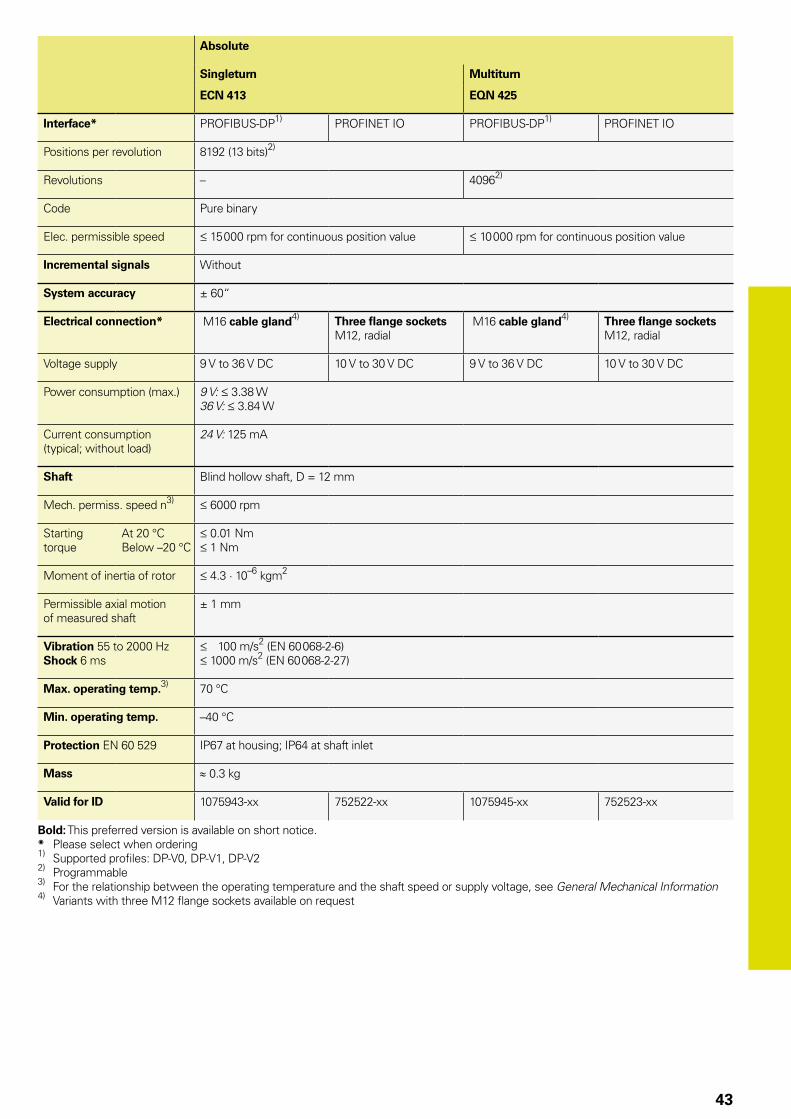
43
Absolute
Singleturn Multiturn
ECN 413 EQN 425
Interface* PROFIBUS-DP1) PROFINET IO PROFIBUS-DP1) PROFINET IO
Positions per revolution 8192 (13 bits)2)
Revolutions – 40962)
Code Pure binary
Elec. permissible speed 15 000 rpm for continuous position value 10 000 rpm for continuous position value
Incremental signals Without
System accuracy ± 60“
Electrical connection* M16 cable gland4) Three flange sockets M12, radial
M16 cable gland4) Three flange sockets M12, radial
Voltage supply 9 V to 36 V DC 10 V to 30 V DC 9 V to 36 V DC 10 V to 30 V DC
Power consumption (max.) 9 V: 3.38 W36 V: 3.84 W
Current consumption (typical; without load)
24 V: 125 mA
Shaft Blind hollow shaft, D = 12 mm
Mech. permiss. speed n3) 6000 rpm
Starting torque
At 20 °CBelow –20 °C
0.01 Nm 1 Nm
Moment of inertia of rotor 4.3 · 10–6 kgm2
Permissible axial motion of measured shaft
± 1 mm
Vibration 55 to 2000 HzShock 6 ms
100 m/s2 (EN 60 068-2-6) 1000 m/s2 (EN 60 068-2-27)
Max. operating temp.3) 70 °C
Min. operating temp. –40 °C
Protection EN 60 529 IP67 at housing; IP64 at shaft inlet
Mass ≈ 0.3 kg
Valid for ID 1075943-xx 752522-xx 1075945-xx 752523-xx
Bold: This preferred version is available on short notice.* Please select when ordering1) Supported profiles: DP-V0, DP-V1, DP-V22) Programmable3) For the relationship between the operating temperature and the shaft speed or supply voltage, see General Mechanical Information4) Variants with three M12 flange sockets available on request

44
ECN/EQN/ERN 400 seriesAbsolute and incremental rotary encoders• Stator coupling for universal mounting • Blind hollow shaft or hollow through shaft
Blind hollow shaft
Hollow through shaft
Cable radial, also usable axiallyA = Bearing of mating shaftk = Required mating dimensionsm = Measuring point for operating temperature = Clamping screw with X8 hexalobular socket = Hole pattern for fastening, see coupling = Compensation of mounting tolerances and thermal expansion, no dynamic motion permitted = Direction of shaft rotation for output signals as per the interface description1 = Clamping ring on housing side (condition upon delivery)2 = Clamping ring on coupling side (optionally mountable)
Connector codingA = Axial, R = Radial
Flange socket

45
Incremental
ERN 420 ERN 460 ERN 430 ERN 480
Interface « TTL « HTL » 1 VPP1)
Line counts* 250 500 –
1000 1024 1250 2000 2048 2500 3600 4096 5000
Reference mark One
Cutoff frequency –3 dBOutput frequencyEdge separation a
– 300 kHz 0.39 µs
180 kHz––
System accuracy 1/20 of grating period
Electrical connection* • M23 flange socket, radial and axial (with blind hollow shaft)• Cable 1 m, without connecting element
Voltage supply 5 V DC ± 0.5 V 10 V to 30 V DC 10 V to 30 V DC 5 V ± 0.5 V DC
Current consumption without load
120 mA 100 mA 150 mA 120 mA
Shaft* Blind hollow shaft or hollow through shaft; D = 8 mm or D = 12 mm
Mech. permiss. speed n2) 6000 rpm/ 12 000 rpm 3)
Starting torque
At 20 °C
Below –20 °C
Blind hollow shaft: 0.01 NmHollow through shaft: 0.025 Nm (for IP66: 0.075 Nm) 1 Nm
Moment of inertia of rotor 4.3 · 10–6 kgm2
Permissible axial motion of measured shaft
± 1 mm
Vibration 55 to 2000 HzShock 6 ms
300 m/s2; Flange socket version: 150 m/s2 (EN 60 068-2-6); higher values upon request 1000 m/s2 (EN 60 068-2-27)
Max. operating temp. 2) 100 °C 70 °C 100 °C4)
Min. operating temp. Flange socket or fixed cable: –40 °C; moving cable: –10 °C
Protection EN 60 529 At housing: IP67 (IP66 for hollow through shaft)At shaft inlet: IP64 (with D = 12 mm, IP66 available on request)
Mass ≈ 0.3 kg
Valid for ID 385424-xx 385464-xx 385434-xx 385483-xx
Bold: This preferred version is available on short notice.* Please select when ordering1) Restricted tolerances: Signal amplitude 0.8 to 1.2 VPP2) For the relationship between the operating temperature and the shaft speed or supply voltage, see General Mechanical Information3) With two shaft clamps (only for hollow through shaft)4) 80° for ERN 480 with 4096 or 5000 lines

46
Absolute
Singleturn Multiturn
ECN 425 ECN 413 ECN 413 EQN 437 EQN 425 EQN 425
Interface* EnDat 2.2 EnDat 2.2 SSI EnDat 2.2 EnDat 2.2 SSI
Ordering designation EnDat22 EnDat01 SSI39r1 EnDat22 EnDat01 SSI41r1
Positions per revolution 33 554 432 (25 bits) 8192 (13 bits) 33 554 432 (25 bits) 8192 (13 bits)
Revolutions – 4096
Code Pure binary Gray Pure binary Gray
Elec. permissible speedDeviations1)
12 000 rpm for continuous position value
512 lines: 5000/12 000 rpm
± 1 LSB/± 100 LSB2048 lines: 1500/12 000 rpm
± 1 LSB/± 50 LSB
12 000 rpm± 12 LSB
12 000 rpmfor continuous position value
512 lines: 5000/10 000 rpm
± 1 LSB/± 100 LSB2048 lines: 1500/10 000 rpm
± 1 LSB/± 50 LSB
12 000 rpm± 12 LSB
Calculation time tcalClock frequency
7 µs 8 MHz
9 µs 2 MHz
5 µs–
7 µs 8 MHz
9 µs 2 MHz
5 µs–
Incremental signals Without » 1 VPP2) Without » 1 VPP
2)
Line counts* – 512 2048 512 – 512 2048 512
Cutoff frequency –3 dBOutput frequency
––
512 lines: 130 kHz; 2048 lines: 400 kHz–
––
512 lines: 130 kHz; 2048 lines: 400 kHz–
System accuracy ± 20“ 512 lines: ± 60“; 2048 lines: ± 20“ ± 20“ 512 lines: ± 60“; 2048 lines: ± 20“
Electrical connection* • Flange socket M12, radial• Cable 1 m, with M12 coupling
• Flange socket M23, radial• Cable 1 m, with M23 coupling or without connecting element
• Flange socket M12, radial• Cable 1 m, with M12 coupling
• Flange socket M23, radial• Cable 1 m, with M23 coupling or without connecting element
Voltage supply* 3.6 V to 14 V DC 3.6 V to 14 V DC 4.75 V DC to 30 V 3.6 V to 14 V DC 3.6 V to 14 V DC 4.75 V DC to 30 V
Power consumption (maximum)
3.6 V: 0.6 W14 V: 0.7 W
5 V: 0.8 W10 V: 0.65 W30 V: 1 W
3.6 V: 0.7 W14 V: 0.8 W
5 V: 0.95 W10 V: 0.75 W30 V: 1.1 W
Current consumption (typical; without load)
5 V: 85 mA 5 V: 90 mA24 V: 24 mA
5 V: 105 mA 5 V: 120 mA24 V: 28 mA
Shaft* Blind hollow shaft or hollow through shaft; D = 8 mm or D = 12 mm
Mech. perm. speed n3) 6000 rpm/ 12 000 rpm 4)
Starting torque
At 20 °C
Below –20 °C
Blind hollow shaft: 0.01 NmHollow through shaft: 0.025 Nm (for IP66: 0.075 Nm) 1 Nm
Moment of inertia of rotor 4.3 · 10–6 kgm2
Permissible axial motion of measured shaft
± 1 mm
Vibration 55 to 2000 HzShock 6 ms
300 m/s2; Flange socket version: 150 m/s2 (EN 60 068-2-6); higher values upon request 2000 m/s2 (EN 60 068-2-27)
Max. operating temp.3) 100 °C
Min. operating temp. Flange socket or fixed cable:–40 °C; moving cable: –10 °C
Protection EN 60 529 At housing: IP67 (IP66 for hollow through shaft)At shaft inlet: IP64 (with D = 12 mm, IP66 available on request)
Mass ≈ 0.3 kg
Valid for ID 683644-xx 1065932-xx 1132405-xx 683646-xx 1109258-xx 1132407-xx
Bold: This preferred version is available on short notice. * Please select when ordering1) Speed-dependent deviations between the absolute value and incremental signal 2) Restricted tolerances: Signal amplitude 0.8 to 1.2 VPP
3) For the relationship between the operating temperature and the shaft speed or power supply, see General Mechanical Information4) With two shaft clamps (only for hollow through shaft)

47
Absolute
Singleturn Multiturn
ECN 425 ECN 413 ECN 413 EQN 437 EQN 425 EQN 425
Interface* EnDat 2.2 EnDat 2.2 SSI EnDat 2.2 EnDat 2.2 SSI
Ordering designation EnDat22 EnDat01 SSI39r1 EnDat22 EnDat01 SSI41r1
Positions per revolution 33 554 432 (25 bits) 8192 (13 bits) 33 554 432 (25 bits) 8192 (13 bits)
Revolutions – 4096
Code Pure binary Gray Pure binary Gray
Elec. permissible speedDeviations1)
12 000 rpm for continuous position value
512 lines: 5000/12 000 rpm
± 1 LSB/± 100 LSB2048 lines: 1500/12 000 rpm
± 1 LSB/± 50 LSB
12 000 rpm± 12 LSB
12 000 rpmfor continuous position value
512 lines: 5000/10 000 rpm
± 1 LSB/± 100 LSB2048 lines: 1500/10 000 rpm
± 1 LSB/± 50 LSB
12 000 rpm± 12 LSB
Calculation time tcalClock frequency
7 µs 8 MHz
9 µs 2 MHz
5 µs–
7 µs 8 MHz
9 µs 2 MHz
5 µs–
Incremental signals Without » 1 VPP2) Without » 1 VPP
2)
Line counts* – 512 2048 512 – 512 2048 512
Cutoff frequency –3 dBOutput frequency
––
512 lines: 130 kHz; 2048 lines: 400 kHz–
––
512 lines: 130 kHz; 2048 lines: 400 kHz–
System accuracy ± 20“ 512 lines: ± 60“; 2048 lines: ± 20“ ± 20“ 512 lines: ± 60“; 2048 lines: ± 20“
Electrical connection* • Flange socket M12, radial• Cable 1 m, with M12 coupling
• Flange socket M23, radial• Cable 1 m, with M23 coupling or without connecting element
• Flange socket M12, radial• Cable 1 m, with M12 coupling
• Flange socket M23, radial• Cable 1 m, with M23 coupling or without connecting element
Voltage supply* 3.6 V to 14 V DC 3.6 V to 14 V DC 4.75 V DC to 30 V 3.6 V to 14 V DC 3.6 V to 14 V DC 4.75 V DC to 30 V
Power consumption (maximum)
3.6 V: 0.6 W14 V: 0.7 W
5 V: 0.8 W10 V: 0.65 W30 V: 1 W
3.6 V: 0.7 W14 V: 0.8 W
5 V: 0.95 W10 V: 0.75 W30 V: 1.1 W
Current consumption (typical; without load)
5 V: 85 mA 5 V: 90 mA24 V: 24 mA
5 V: 105 mA 5 V: 120 mA24 V: 28 mA
Shaft* Blind hollow shaft or hollow through shaft; D = 8 mm or D = 12 mm
Mech. perm. speed n3) 6000 rpm/ 12 000 rpm 4)
Starting torque
At 20 °C
Below –20 °C
Blind hollow shaft: 0.01 NmHollow through shaft: 0.025 Nm (for IP66: 0.075 Nm) 1 Nm
Moment of inertia of rotor 4.3 · 10–6 kgm2
Permissible axial motion of measured shaft
± 1 mm
Vibration 55 to 2000 HzShock 6 ms
300 m/s2; Flange socket version: 150 m/s2 (EN 60 068-2-6); higher values upon request 2000 m/s2 (EN 60 068-2-27)
Max. operating temp.3) 100 °C
Min. operating temp. Flange socket or fixed cable:–40 °C; moving cable: –10 °C
Protection EN 60 529 At housing: IP67 (IP66 for hollow through shaft)At shaft inlet: IP64 (with D = 12 mm, IP66 available on request)
Mass ≈ 0.3 kg
Valid for ID 683644-xx 1065932-xx 1132405-xx 683646-xx 1109258-xx 1132407-xx
Bold: This preferred version is available on short notice. * Please select when ordering1) Speed-dependent deviations between the absolute value and incremental signal 2) Restricted tolerances: Signal amplitude 0.8 to 1.2 VPP
3) For the relationship between the operating temperature and the shaft speed or power supply, see General Mechanical Information4) With two shaft clamps (only for hollow through shaft)
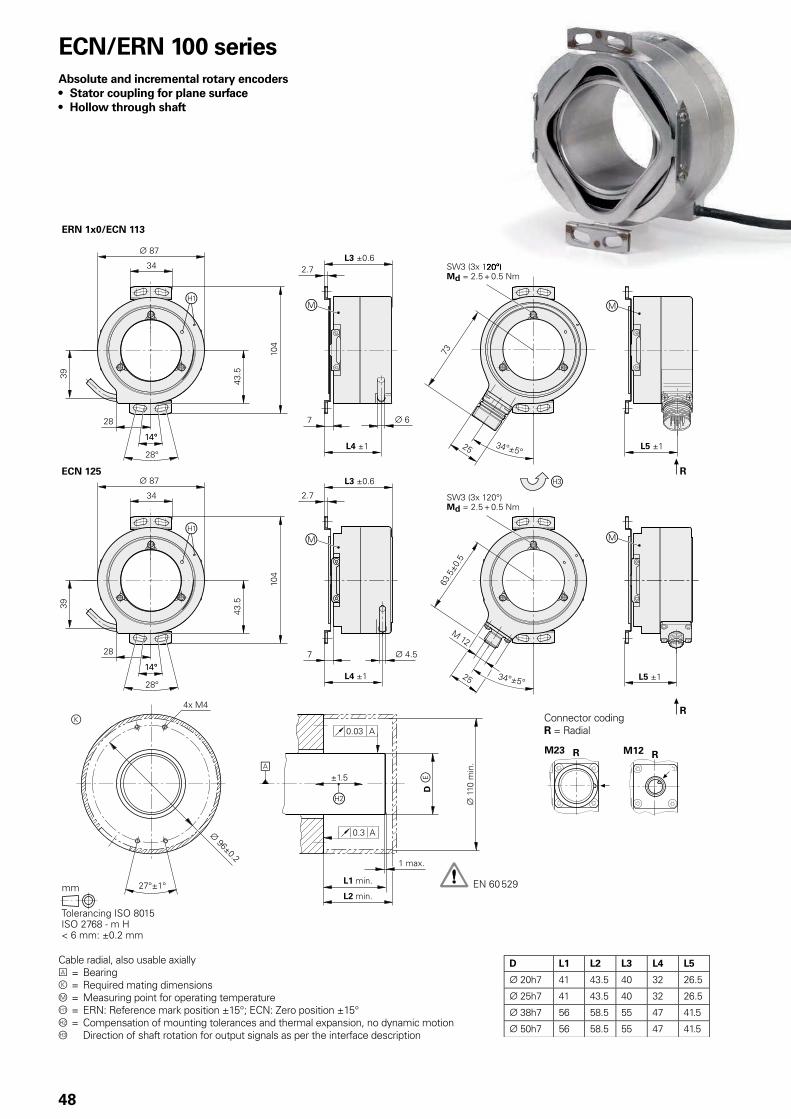
D L1 L2 L3 L4 L5
20h7 41 43.5 40 32 26.5
25h7 41 43.5 40 32 26.5
38h7 56 58.5 55 47 41.5
50h7 56 58.5 55 47 41.5
48
ECN/ERN 100 seriesAbsolute and incremental rotary encoders• Stator coupling for plane surface• Hollow through shaft
Cable radial, also usable axiallyA = Bearingk = Required mating dimensionsm = Measuring point for operating temperature = ERN: Reference mark position ±15°; ECN: Zero position ±15° = Compensation of mounting tolerances and thermal expansion, no dynamic motion Direction of shaft rotation for output signals as per the interface description
Connector codingR = Radial
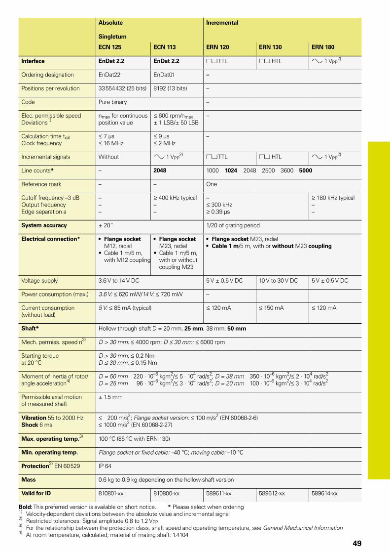
49
Absolute Incremental
Singleturn
ECN 125 ECN 113 ERN 120 ERN 130 ERN 180
Interface EnDat 2.2 EnDat 2.2 « TTL « HTL » 1 VPP2)
Ordering designation EnDat22 EnDat01 –
Positions per revolution 33 554 432 (25 bits) 8192 (13 bits) –
Code Pure binary –
Elec. permissible speedDeviations1)
nmax for continuous position value
600 rpm/nmax± 1 LSB/± 50 LSB
–
Calculation time tcalClock frequency
7 µs 16 MHz
9 µs 2 MHz
–
Incremental signals Without » 1 VPP2) « TTL « HTL » 1 VPP
2)
Line counts* – 2048 1000 1024 2048 2500 3600 5000
Reference mark – – One
Cutoff frequency –3 dBOutput frequencyEdge separation a
–––
400 kHz typical––
– 300 kHz 0.39 µs
180 kHz typical––
System accuracy ± 20“ 1/20 of grating period
Electrical connection* • Flange socket M12, radial
• Cable 1 m/5 m, with M12 coupling
• Flange socket M23, radial
• Cable 1 m/5 m, with or without coupling M23
• Flange socket M23, radial• Cable 1 m/5 m, with or without M23 coupling
Voltage supply 3.6 V to 14 V DC 5 V ± 0.5 V DC 10 V to 30 V DC 5 V ± 0.5 V DC
Power consumption (max.) 3.6 V: 620 mW/14 V: 720 mW –
Current consumption (without load)
5 V: 85 mA (typical) 120 mA 150 mA 120 mA
Shaft* Hollow through shaft D = 20 mm, 25 mm, 38 mm, 50 mm
Mech. permiss. speed n3) D > 30 mm: 4000 rpm; D 30 mm: 6000 rpm
Starting torqueat 20 °C
D > 30 mm: 0.2 NmD 30 mm: 0.15 Nm
Moment of inertia of rotor/angle acceleration4)
D = 50 mm 220 · 10–6 kgm2/ 5 · 104 rad/s2; D = 38 mm 350 · 10–6 kgm2/ 2 · 104 rad/s2
D = 25 mm 96 · 10–6 kgm2/ 3 · 104 rad/s2; D = 20 mm 100 · 10–6 kgm2/ 3 · 104 rad/s2
Permissible axial motion of measured shaft
± 1.5 mm
Vibration 55 to 2000 HzShock 6 ms
200 m/s2; Flange socket version: 100 m/s2 (EN 60 068-2-6) 1000 m/s2 (EN 60 068-2-27)
Max. operating temp.3) 100 °C (85 °C with ERN 130)
Min. operating temp. Flange socket or fixed cable: –40 °C; moving cable: –10 °C
Protection3) EN 60 529 IP 64
Mass 0.6 kg to 0.9 kg depending on the hollow-shaft version
Valid for ID 810801-xx 810800-xx 589611-xx 589612-xx 589614-xx
Bold: This preferred version is available on short notice. * Please select when ordering1) Velocity-dependent deviations between the absolute value and incremental signal2) Restricted tolerances: Signal amplitude 0.8 to 1.2 VPP3) For the relationship between the protection class, shaft speed and operating temperature, see General Mechanical Information4) At room temperature, calculated; material of mating shaft: 1.4104
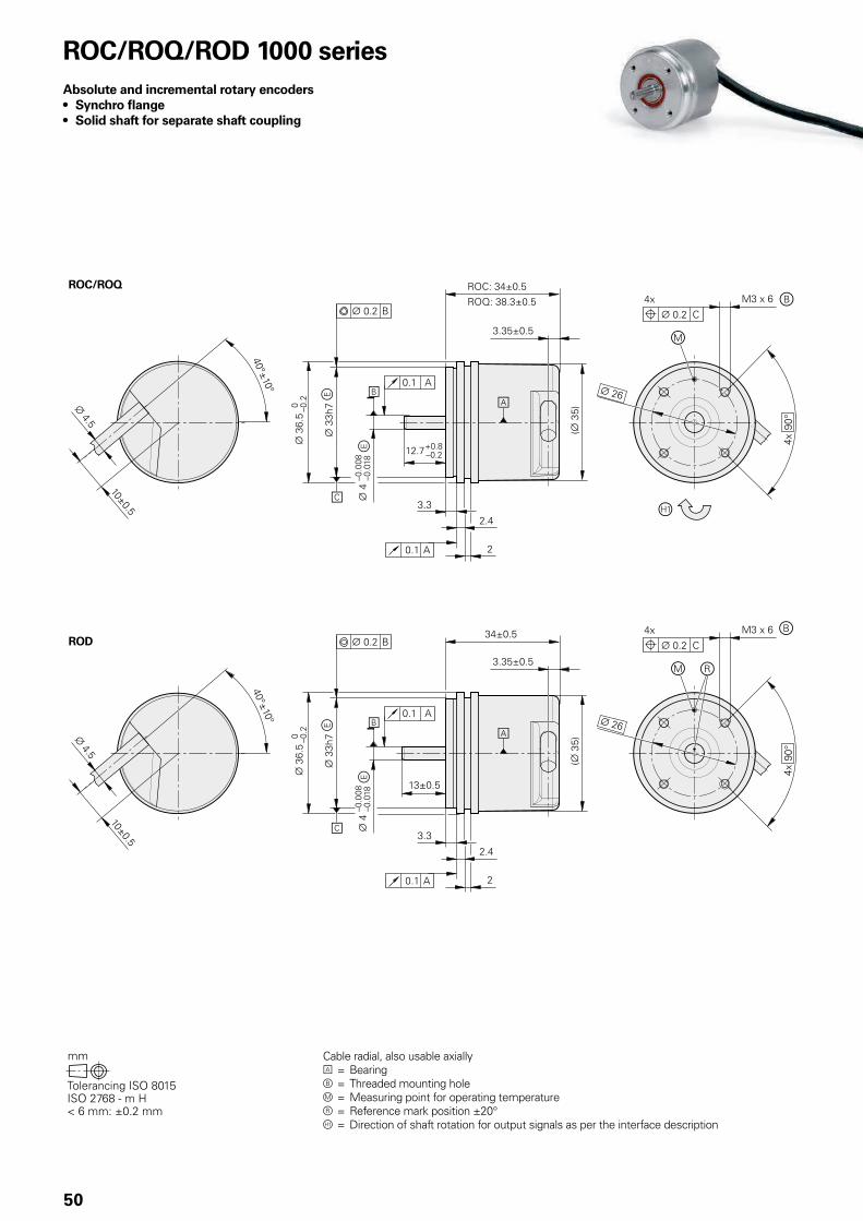
50
ROC/ROQ/ROD 1000 seriesAbsolute and incremental rotary encoders• Synchro flange• Solid shaft for separate shaft coupling
Cable radial, also usable axiallyA = Bearingb = Threaded mounting holem = Measuring point for operating temperaturer = Reference mark position ±20° = Direction of shaft rotation for output signals as per the interface description

51
Incremental
ROD 1020 ROD 1030 ROD 1080 ROD 1070
Interface « TTL « HTLs » 1 VPP1) « TTL
Line counts* 100 200 250 360 400 500 720 9001000 1024 1250 1500 2000 2048 2500 3600
1000 2500 3600
Reference mark One
Integrated interpolation* – 5-fold 10-fold
Cutoff frequency –3 dBScanning frequencyEdge separation a
– 300 kHz 0.39 µs
– 160 kHz 0.76 µs
180 kHz––
– 100 kHz 0.47 µs
– 100 kHz 0.22 µs
System accuracy 1/20 of grating period
Electrical connection Cable 1 m/5 m, with or without M23 coupling Cable 5 m without M23 coupling
Voltage supply 5 V DC ± 0.5 V 10 V to 30 V DC 5 V ± 0.5 V DC 5 V DC ± 5 %
Current consumption without load
120 mA 150 mA 120 mA 155 mA
Shaft Solid shaft D = 4 mm
Mech. permiss. speed n 12 000 rpm
Starting torque 0.001 Nm (at 20 °C)
Moment of inertia of rotor 0.5 · 10–6 kgm2
Shaft load Axial: 5 NRadial: 10 N at shaft end
Vibration 55 to 2000 HzShock 6 ms
100 m/s2 (EN 60 068-2-6) 1000 m/s2 (EN 60 068-2-27)
Max. operating temp. 2) 100 °C 70 °C 100 °C 70 °C
Min. operating temp. Stationary cable: –30 °C; moving cable: –10 °C
Protection EN 60 529 IP 64
Mass ≈ 0.09 kg
Valid for ID 534900-x 534901-xx 534904-xx 534903-xx
Bold: This preferred version is available on short notice.* Please select when ordering1) Restricted tolerances: Signal amplitude: 0.8 to 1.2 VPP2) For the correlation between the operating temperature and the shaft speed or power supply, see General Mechanical Information

52
Absolute
Singleturn Multiturn
ROC 1023 ROC 1013 ROQ 1035 ROQ 1025
Interface EnDat 2.2 EnDat 2.2 SSI EnDat 2.2 EnDat 2.2 SSI
Ordering designation EnDat22 EnDat01 SSI39r1 EnDat22 EnDat01 SSI41r1
Positions per revolution 8 388 608 (23 bits) 8192 (13 bits) 8 388 608 (23 bits) 8192 (13 bits)
Revolutions – 4 096 (12 bits)
Code Pure binary Gray Pure binary Gray
Elec. permissible speedDeviations1)
12 000 rpmfor continuous position value
4000 rpm/ 12 000 rpm± 1 LSB/± 16 LSB
12 000 rpm± 12 LSB
12 000 rpmfor continuous position value
4000 rpm/ 12 000 rpm± 1 LSB/± 16 LSB
12 000 rpm± 12 LSB
Calculation time tcalClock frequency
7 µs 8 MHz
9 µs 2 MHz
5 µs 1 MHz
7 µs 8 MHz
9 µs 2 MHz
5 µs 1 MHz
Incremental signals – » 1 VPP2) – » 1 VPP
2)
Line count – 512 – 512
Cutoff frequency –3 dB – 190 kHz – 190 kHz
System accuracy ± 60“
Electrical connection Cable 1 m, with M12 coupling Cable 1 m, with M23 coupling Cable 1 m, with M12 coupling Cable 1 m, with M23 coupling
Voltage supply 3.6 V to 14 V DC 4.75 V DC to 30 V 3.6 V to 14 V DC 4.75 V DC to 30 V
Power consumption (maximum)
3.6 V: 0.6 W14 V: 0.7 W
4.75 V: 0.53 W30 V: 0.86 W
3.6 V: 0.7 W14 V: 0.8 W
4.75 V: 0.65 W30 V: 1.05 W
Current consumption (typical; without load)
5 V: 85 mA 5 V: 70 mA24 V: 20 mA
5 V: 105 mA 5 V: 85 mA24 V: 25 mA
Shaft Stub shaft ¬ 4 mm
Mech. permiss. speed n 12 000 rpm
Starting torque 0.001 Nm (at 20 °C) 0.002 Nm (at 20 °C)
Moment of inertia of rotor ≈ 0.5 · 10–6 kgm2
Shaft load Axial: 5 NRadial: 10 N at shaft end
Vibration 55 to 2000 HzShock 6 ms
100 m/s2 (EN 60 068-2-6) 1000 m/s2 (EN 60 068-2-27)
Max. operating temp. 100 °C
Min. operating temp. Stationary cable: –30 °C; moving cable: –10 °C
Protection EN 60 529 IP 64
Mass ≈ 0.09 kg
Valid for ID 606693-xx 606691-xx 606692-xx 606696-xx 606694-xx 606695-xx
1) Velocity-dependent deviations between the absolute and incremental signals2) Restricted tolerances: Signal amplitude 0.80 to 1.2 VPP

53
Absolute
Singleturn Multiturn
ROC 1023 ROC 1013 ROQ 1035 ROQ 1025
Interface EnDat 2.2 EnDat 2.2 SSI EnDat 2.2 EnDat 2.2 SSI
Ordering designation EnDat22 EnDat01 SSI39r1 EnDat22 EnDat01 SSI41r1
Positions per revolution 8 388 608 (23 bits) 8192 (13 bits) 8 388 608 (23 bits) 8192 (13 bits)
Revolutions – 4 096 (12 bits)
Code Pure binary Gray Pure binary Gray
Elec. permissible speeddeviations1)
12 000 rpmfor continuous position value
4000 rpm/ 12 000 rpm± 1 LSB/± 16 LSB
12 000 rpm± 12 LSB
12 000 rpmfor continuous position value
4000 rpm/ 12 000 rpm± 1 LSB/± 16 LSB
12 000 rpm± 12 LSB
Calculation time tcalClock frequency
7 µs 8 MHz
9 µs 2 MHz
5 µs 1 MHz
7 µs 8 MHz
9 µs 2 MHz
5 µs 1 MHz
Incremental signals – » 1 VPP2) – » 1 VPP
2)
Line count – 512 – 512
Cutoff frequency –3 dB – 190 kHz – 190 kHz
System accuracy ± 60“
Electrical connection Cable 1 m, with M12 coupling Cable 1 m, with M23 coupling Cable 1 m, with M12 coupling Cable 1 m, with M23 coupling
Voltage supply 3.6 V to 14 V DC 4.75 V DC to 30 V 3.6 V to 14 V DC 4.75 V DC to 30 V
Power consumption (maximum)
3.6 V: 0.6 W14 V: 0.7 W
4.75 V: 0.53 W30 V: 0.86 W
3.6 V: 0.7 W14 V: 0.8 W
4.75 V: 0.65 W30 V: 1.05 W
Current consumption (typical; without load)
5 V: 85 mA 5 V: 70 mA24 V: 20 mA
5 V: 105 mA 5 V: 85 mA24 V: 25 mA
Shaft Stub shaft ¬ 4 mm
Mech. permiss. speed n 12 000 rpm
Starting torque 0.001 Nm (at 20 °C) 0.002 Nm (at 20 °C)
Moment of inertia of rotor ≈ 0.5 · 10–6 kgm2
Shaft load Axial: 5 NRadial: 10 N at shaft end
Vibration 55 to 2000 HzShock 6 ms
100 m/s2 (EN 60 068-2-6) 1000 m/s2 (EN 60 068-2-27)
Max. operating temp. 100 °C
Min. operating temp. Stationary cable: –30 °C; moving cable: –10 °C
Protection EN 60 529 IP 64
Mass ≈ 0.09 kg
Valid for ID 606693-xx 606691-xx 606692-xx 606696-xx 606694-xx 606695-xx
1) Velocity-dependent deviations between the absolute and incremental signals2) Restricted tolerances: Signal amplitude 0.80 to 1.2 VPP
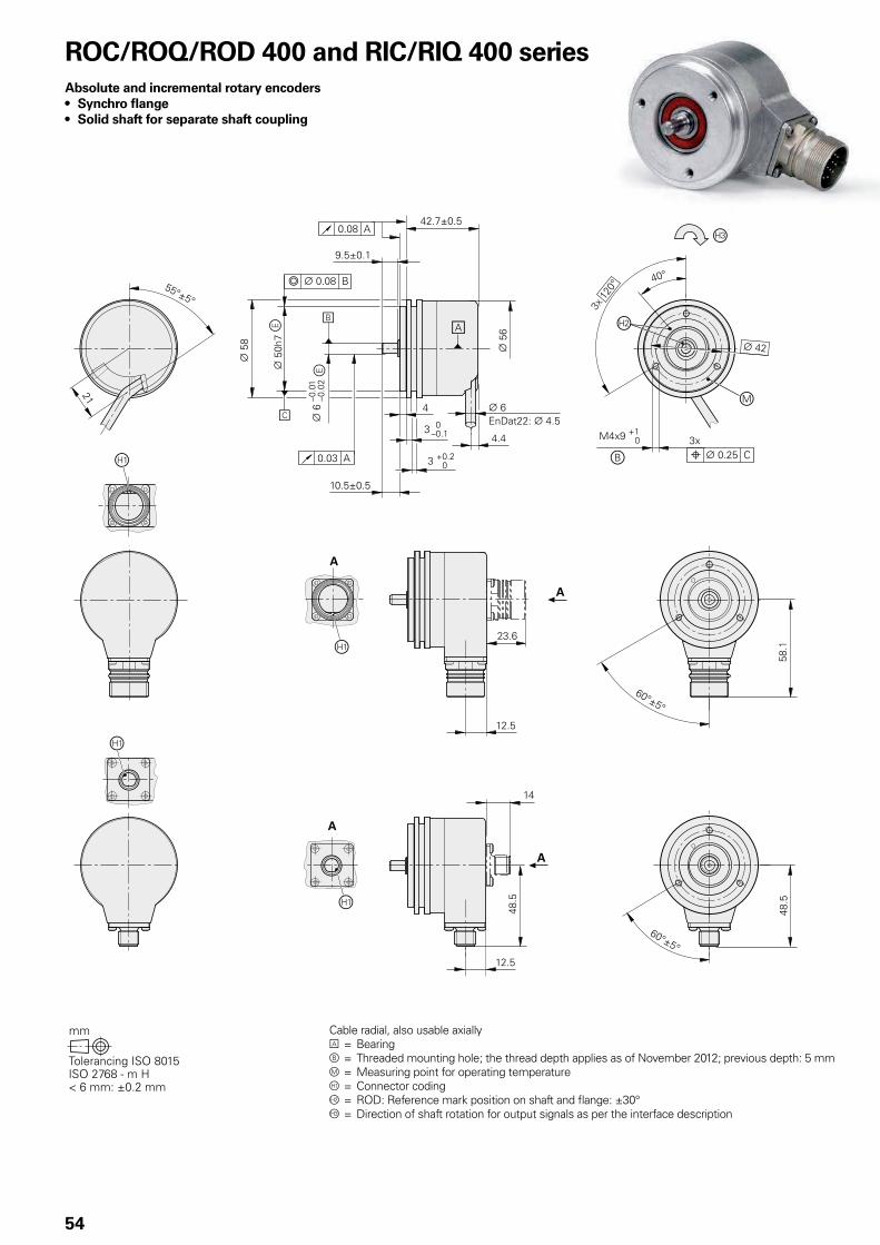
54
ROC/ROQ/ROD 400 and RIC/RIQ 400 seriesAbsolute and incremental rotary encoders• Synchro flange• Solid shaft for separate shaft coupling
Cable radial, also usable axiallyA = Bearingb = Threaded mounting hole; the thread depth applies as of November 2012; previous depth: 5 mmm = Measuring point for operating temperature = Connector coding = ROD: Reference mark position on shaft and flange: ±30°Â = Direction of shaft rotation for output signals as per the interface description

55
Incremental
ROD 426 ROD 466 ROD 436 ROD 486
Interface « TTL « HTL » 1 VPP1)
Line counts* 50 100 150 200 250 360 500 512 720 –
1000 1024 1250 1500 1800 2000 2048 2500 3600 4096 5000
60002) 81922) 90002) 10 0002) –
Reference mark One
Cutoff frequency –3 dBScanning frequencyEdge separation a
– 300 kHz/ 150 kHz2)
0.39 µs/ 0.25 µs2)
180 kHz––
System accuracy 1/20 of grating period
Electrical connection* • Flange socket M23, radial and axial• Cable 1 m/5 m, with or without M23 coupling
Voltage supply 5 V DC ± 0.5 V 10 V to 30 V DC 10 V to 30 V DC 5 V ± 0.5 V DC
Current consumption without load
120 mA 100 mA 150 mA 120 mA
Shaft Solid shaft D = 6 mm
Mech. permiss. speed n 16 000 rpm
Starting torque 0.01 Nm (at 20 °C)
Moment of inertia of rotor 2.7 · 10–6 kgm2
Shaft load3) Axial: 40 N; radial: 60 N at shaft end
Vibration 55 to 2000 HzShock 6 ms
300 m/s2 (EN 60 068-2-6) 2000 m/s2 (EN 60 068-2-27)
Max. operating temp. 4) 100 °C 70 °C 100 °C5)
Min. operating temp. Flange socket or fixed cable: –40 °C; moving cable: –10 °C
Protection EN 60 529 Degree of protection IP67 at housing; IP64 at shaft inlet (IP66 upon request)
Mass ≈ 0.3 kg
Valid for ID 376846-xx 376866-xx 376836-xx 376886-xx
Bold: This preferred version is available on short notice.* Please select when ordering1) Restricted tolerances: Signal amplitude: 0.8 to 1.2 VPP2) Signal periods; generated through integrated 2-fold interpolation (TTL x 2)3) See also Mechanical design types and mounting4) For the relationship between the operating temperature and the shaft speed or power supply, see General mechanical information5) 80 °C for ROD 486 with 4096 or 5000 lines

56
Absolute
Singleturn Multiturn
ROC 425 ROC 413 RIC 418 ROQ 437 ROQ 425 RIQ 430
Interface* EnDat 2.2 EnDat 2.2 SSI EnDat 2.1 EnDat 2.2 EnDat 2.2 SSI EnDat 2.1
Ordering designation EnDat22 EnDat01 SSI39r1 EnDat01 EnDat22 EnDat01 SSI41r1 EnDat01
Positions per revolution 33 554 432 (25 bits) 8192 (13 bits) 262 144 (18 bits) 33 554 432 (25 bits) 8192 (13 bits) 8192 (13 bits) 262 144 (18 bits)
Revolutions – 4096 4096
Code Pure binary Gray Pure binary Pure binary Gray Pure binary
Elec. permissible speedDeviations1)
15 000 rpm for continuous position value
512 lines: 5000/12 000 rpm± 1 LSB/± 100 LSB2048 lines: 1500/12 000 rpm± 1 LSB/± 50 LSB
12 000 rpm± 12 LSB
4000/15 000 rpm± 400 LSB/± 800 LSB
15 000 rpm for continuous position value
512 lines: 5000/10 000 rpm± 1 LSB/± 100 LSB2048 lines: 1500/10 000 rpm± 1 LSB/± 50 LSB
12 000 rpm± 12 LSB
4000/15 000 rpm± 400 LSB/± 800 LSB
Calculation time tcalClock frequency
7 µs 8 MHz
9 µs 2 MHz
5 µs–
8 µs 2 MHz
7 µs 8 MHz
9 µs 2 MHz
5 µs–
8 µs 2 MHz
Incremental signals Without » 1 VPP2) » 1 VPP Without » 1 VPP
2) » 1 VPP
Line counts* – 512 2048 512 16 – 512 2048 512 16
Cutoff frequency –3 dB – 512 lines: 130 kHz; 2048 lines: 400 kHz 6 kHz – 512 lines: 130 kHz; 2048 lines: 400 kHz 6 kHz
System accuracy ± 20“ 512 lines: ± 60“; 2048 lines: ± 20“ ± 480“ ± 20“ 512 lines: ± 60“; 2048 lines: ± 20“ ± 480“
Electrical connection* • Flange socket M12, radial• Cable 1 m, with
M12 coupling
• Flange socket M23, axial or radial• Cable 1 m/5 m, with or without M23 coupling
• Flange socket M23, radial• Cable 1 m, with M23
coupling
• Flange socket M12, radial• Cable 1 m, with M12 coupling
• Flange socket M23, axial or radial• Cable 1 m/5 m, with or without M23 coupling
• Flange socket M23, radial• Cable 1 m, with M23 coupling
Voltage supply* 3.6 V to 14 V DC 3.6 V to 14 V DC 4.75 V DC to 30 V 5 V DC ± 0.25 V 3.6 V to 14 V DC 3.6 V to 14 V DC 4.75 V DC to 30 V 5 V DC ± 0.25 V
Power consumption (max.)
3.6 V: 0.6 W14 V: 0.7 W
5 V: 0.8 W 10 V: 0.65 W30 V: 1 W
5 V: 0.95 W 3.6 V: 0.7 W14 V: 0.8 W
5 V: 0.95 W 10 V: 0.75 W30 V: 1.1 W
5 V: 1.1 W
Current consumption (typical; without load)
5 V: 85 mA 5 V: 90 mA24 V: 24 mA
5 V: 125 mA 5 V: 105 mA 5 V: 120 mA24 V: 28 mA
5 V: 150 mA
Shaft Solid shaft D = 6 mm
Mech. permiss. speed n 15 000 rpm 12 000 rpm
Starting torque 0.01 Nm (at 20 °C)
Moment of inertia of rotor 2.7 · 10–6 kgm2
Shaft load Axial: 40 N; radial: 60 N at shaft end (see also Mechanical design types and mounting)
Vibration 55 to 2000 HzShock 6 ms
300 m/s2 (EN 60 068-2-6)ROC/ROQ: 2000 m/s2; RIC/RIQ: 1000 m/s2 (EN 60 068-2-27)
Max. operating temp.3) 100 °C
Min. operating temp. Flange socket or fixed cable: –40 °C; Moving cable: –10 °C
Protection EN 60 529 IP67 at housing, IP64 at shaft inlet3) (IP66 upon request)
Mass ≈ 0.35 kg
Valid for ID 683639-xx 1109254-xx 1131750-xx 642004-xx 683641-xx 1109256-xx 1131752-xx 642000-xx
Bold: This preferred version is available on short notice.* Please select when ordering1) Speed-dependent deviations between the absolute value and incremental signal
2) Restricted tolerances: Signal amplitude 0.8 to 1.2 VPP 3) For the relationship between the operating temperature and shaft speed or power supply, see General Mechanical Information Functional safety available for ROC 425 and ROQ 437. For dimensions and specifications see Product Information

57
Absolute
Singleturn Multiturn
ROC 425 ROC 413 RIC 418 ROQ 437 ROQ 425 RIQ 430
Interface* EnDat 2.2 EnDat 2.2 SSI EnDat 2.1 EnDat 2.2 EnDat 2.2 SSI EnDat 2.1
Ordering designation EnDat22 EnDat01 SSI39r1 EnDat01 EnDat22 EnDat01 SSI41r1 EnDat01
Positions per revolution 33 554 432 (25 bits) 8192 (13 bits) 262 144 (18 bits) 33 554 432 (25 bits) 8192 (13 bits) 8192 (13 bits) 262 144 (18 bits)
Revolutions – 4096 4096
Code Pure binary Gray Pure binary Pure binary Gray Pure binary
Elec. permissible speedDeviations1)
15 000 rpm for continuous position value
512 lines: 5000/12 000 rpm± 1 LSB/± 100 LSB2048 lines: 1500/12 000 rpm± 1 LSB/± 50 LSB
12 000 rpm± 12 LSB
4000/15 000 rpm± 400 LSB/± 800 LSB
15 000 rpm for continuous position value
512 lines: 5000/10 000 rpm± 1 LSB/± 100 LSB2048 lines: 1500/10 000 rpm± 1 LSB/± 50 LSB
12 000 rpm± 12 LSB
4000/15 000 rpm± 400 LSB/± 800 LSB
Calculation time tcalClock frequency
7 µs 8 MHz
9 µs 2 MHz
5 µs–
8 µs 2 MHz
7 µs 8 MHz
9 µs 2 MHz
5 µs–
8 µs 2 MHz
Incremental signals Without » 1 VPP2) » 1 VPP Without » 1 VPP
2) » 1 VPP
Line counts* – 512 2048 512 16 – 512 2048 512 16
Cutoff frequency –3 dB – 512 lines: 130 kHz; 2048 lines: 400 kHz 6 kHz – 512 lines: 130 kHz; 2048 lines: 400 kHz 6 kHz
System accuracy ± 20“ 512 lines: ± 60“; 2048 lines: ± 20“ ± 480“ ± 20“ 512 lines: ± 60“; 2048 lines: ± 20“ ± 480“
Electrical connection* • Flange socket M12, radial• Cable 1 m, with
M12 coupling
• Flange socket M23, axial or radial• Cable 1 m/5 m, with or without M23 coupling
• Flange socket M23, radial• Cable 1 m, with M23
coupling
• Flange socket M12, radial• Cable 1 m, with M12 coupling
• Flange socket M23, axial or radial• Cable 1 m/5 m, with or without M23 coupling
• Flange socket M23, radial• Cable 1 m, with M23 coupling
Voltage supply* 3.6 V to 14 V DC 3.6 V to 14 V DC 4.75 V DC to 30 V 5 V DC ± 0.25 V 3.6 V to 14 V DC 3.6 V to 14 V DC 4.75 V DC to 30 V 5 V DC ± 0.25 V
Power consumption (max.)
3.6 V: 0.6 W14 V: 0.7 W
5 V: 0.8 W 10 V: 0.65 W30 V: 1 W
5 V: 0.95 W 3.6 V: 0.7 W14 V: 0.8 W
5 V: 0.95 W 10 V: 0.75 W30 V: 1.1 W
5 V: 1.1 W
Current consumption (typical; without load)
5 V: 85 mA 5 V: 90 mA24 V: 24 mA
5 V: 125 mA 5 V: 105 mA 5 V: 120 mA24 V: 28 mA
5 V: 150 mA
Shaft Solid shaft D = 6 mm
Mech. permiss. speed n 15 000 rpm 12 000 rpm
Starting torque 0.01 Nm (at 20 °C)
Moment of inertia of rotor 2.7 · 10–6 kgm2
Shaft load Axial: 40 N; radial: 60 N at shaft end (see also Mechanical design types and mounting)
Vibration 55 to 2000 HzShock 6 ms
300 m/s2 (EN 60 068-2-6)ROC/ROQ: 2000 m/s2; RIC/RIQ: 1000 m/s2 (EN 60 068-2-27)
Max. operating temp.3) 100 °C
Min. operating temp. Flange socket or fixed cable: –40 °C; Moving cable: –10 °C
Protection EN 60 529 IP67 at housing, IP64 at shaft inlet3) (IP66 upon request)
Mass ≈ 0.35 kg
Valid for ID 683639-xx 1109254-xx 1131750-xx 642004-xx 683641-xx 1109256-xx 1131752-xx 642000-xx
Bold: This preferred version is available on short notice.* Please select when ordering1) Speed-dependent deviations between the absolute value and incremental signal
2) Restricted tolerances: Signal amplitude 0.8 to 1.2 VPP 3) For the relationship between the operating temperature and shaft speed or power supply, see General Mechanical Information Functional safety available for ROC 425 and ROQ 437. For dimensions and specifications see Product Information

58
ROQ 425Rotary encoder for absolute position values with solid shaft for separate shaft coupling• EnDat interface• Additional incremental signals with TTL or HTL levels
Cable radial, also usable axiallyA = Bearingb = Threaded mounting holeM1 = Measuring point for operating temperatureM2 = Measuring point for vibration, see also D 7747141 = Connector coding2 = Direction of shaft rotation for output signals as per the interface description
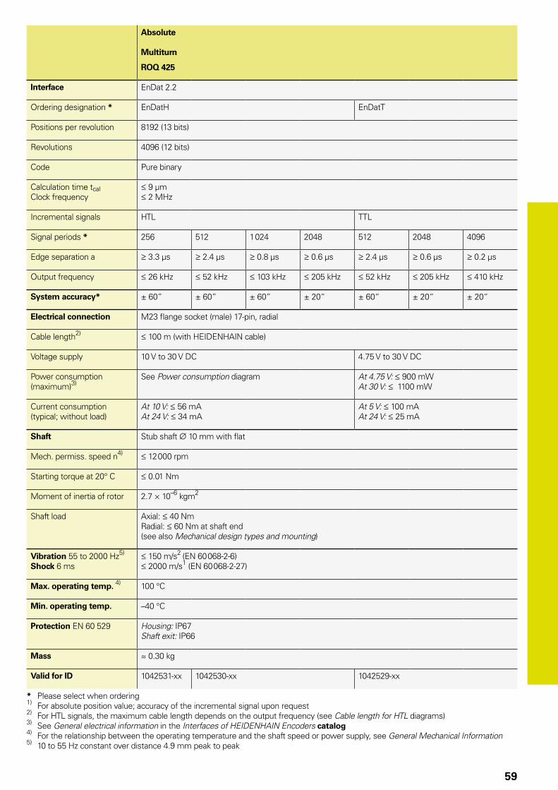
59
Absolute
Multiturn
ROQ 425
Interface EnDat 2.2
Ordering designation * EnDatH EnDatT
Positions per revolution 8192 (13 bits)
Revolutions 4096 (12 bits)
Code Pure binary
Calculation time tcalClock frequency
9 µm 2 MHz
Incremental signals HTL TTL
Signal periods * 256 512 1 024 2048 512 2048 4096
Edge separation a 3.3 µs 2.4 µs 0.8 µs 0.6 µs 2.4 µs 0.6 µs 0.2 µs
Output frequency 26 kHz 52 kHz 103 kHz 205 kHz 52 kHz 205 kHz 410 kHz
System accuracy* ± 60” ± 60” ± 60” ± 20“ ± 60“ ± 20“ ± 20“
Electrical connection M23 flange socket (male) 17-pin, radial
Cable length2) 100 m (with HEIDENHAIN cable)
Voltage supply 10 V to 30 V DC 4.75 V to 30 V DC
Power consumption (maximum)3)
See Power consumption diagram At 4.75 V: 900 mWAt 30 V: 1100 mW
Current consumption (typical; without load)
At 10 V: 56 mAAt 24 V: 34 mA
At 5 V: 100 mAAt 24 V: 25 mA
Shaft Stub shaft ¬ 10 mm with flat
Mech. permiss. speed n4) 12 000 rpm
Starting torque at 20° C 0.01 Nm
Moment of inertia of rotor 2.7 × 10⁻⁶ kgm2
Shaft load Axial: 40 NmRadial: 60 Nm at shaft end (see also Mechanical design types and mounting)
Vibration 55 to 2000 Hz5)
Shock 6 ms 150 m/s2 (EN 60 068-2-6) 2000 m/s1 (EN 60 068-2-27)
Max. operating temp. 4) 100 °C
Min. operating temp. –40 °C
Protection EN 60 529 Housing: IP67Shaft exit: IP66
Mass 0.30 kg
Valid for ID 1042531-xx 1042530-xx 1042529-xx
* Please select when ordering1) For absolute position value; accuracy of the incremental signal upon request2) For HTL signals, the maximum cable length depends on the output frequency (see Cable length for HTL diagrams)3) See General electrical information in the Interfaces of HEIDENHAIN Encoders catalog4) For the relationship between the operating temperature and the shaft speed or power supply, see General Mechanical Information5) 10 to 55 Hz constant over distance 4.9 mm peak to peak
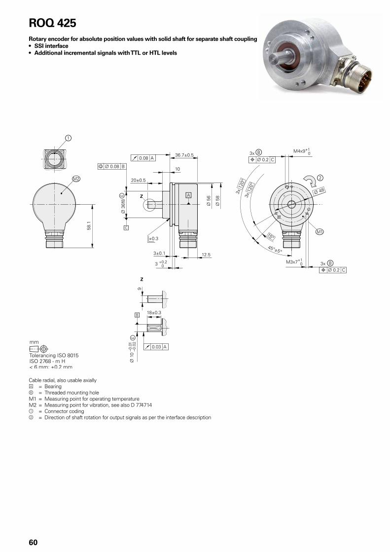
60
ROQ 425Rotary encoder for absolute position values with solid shaft for separate shaft coupling• SSI interface• Additional incremental signals with TTL or HTL levels
Cable radial, also usable axiallyA = Bearingb = Threaded mounting holeM1 = Measuring point for operating temperatureM2 = Measuring point for vibration, see also D 7747141 = Connector coding2 = Direction of shaft rotation for output signals as per the interface description

61
Absolute
Multiturn
ROQ 425
Interface SSI
Ordering designation * SSI41H SSI41T
Positions per revolution 8192 (13 bits)
Revolutions 4096 (12 bits)
Code Pure binary
Calculation time tcalClock frequency
9 µm 2 MHz
Incremental signals HTLs or HTL6) TTL
Signal periods * 256 512 1 024 2048 512 2048 4096
Edge separation a 3.3 µs 2.4 µs 0.8 µs 0.6 µs 2.4 µs 0.6 µs 0.2 µs
Output frequency 26 kHz 52 kHz 103 kHz 205 kHz 52 kHz 205 kHz 410 kHz
System accuracy* ± 60“ ± 60“ ± 60“ ± 20“ ± 60“ ± 20“ ± 20“
Electrical connection M23 flange socket (male) 17-pin, radial
Cable length2) 100 m (with HEIDENHAIN cable)
Voltage supply 10 V to 30 V DC 4.75 V to 30 V DC
Power consumption (maximum)3)
See Power consumption diagram At 4.75 V: 900 mWAt 30 V: 1100 mW
Current consumption (typical; without load)
At 10 V: 56 mAAt 24 V: 34 mA
At 5 V: 100 mAAt 24 V: 25 mA
Shaft Stub shaft ¬ 10 mm with flat
Mech. permiss. speed n4) 12 000 rpm
Starting torque at 20° C 0.01 Nm
Moment of inertia of rotor 2.7 × 10⁻⁶ kgm2
Shaft load Axial: 40 NmRadial: 60 Nm at shaft end (see also Mechanical design types and mounting)
Vibration 55 to 2000 Hz5)
Shock 6 ms 150 m/s2 (EN 60 068-2-6) 2000 m/s1 (EN 60 068-2-27)
Max. operating temp. 4) 100 °C
Min. operating temp. –40 °C
Protection EN 60 529 Housing: IP67Shaft exit: IP66
Mass 0.30 kg
Valid for ID 1042527-xx 1065028-xx 1042524-xx
* Please select when ordering1) For absolute position value; accuracy of the incremental signal upon request2) For HTL signals, the maximum cable length depends on the output frequency (see Cable length for HTL diagrams)3) See General electrical information in the Interfaces of HEIDENHAIN Encoders catalog4) For the relationship between the operating temperature and the shaft speed or power supply, see General Mechanical Information5) 10 to 55 Hz constant over distance 4.9 mm peak to peak6) HTLs upon request

62
ROC/ROQ 400 F/M/S seriesAbsolute rotary encoders• Synchro flange• Solid shaft for separate shaft coupling• Fanuc Serial Interface, Mitsubishi high speed interface
and Siemens DRIVE-CLiQ interface
A = Bearingb = Threaded mounting hole; the thread depth applies as of November 2012; previous depth 5 mmm = Measuring point for operating temperature = Connector coding = Direction of shaft rotation for output signals as per the interface description
ROC/ROQ 400 F/M
ROC/ROQ 400 S

63
Absolute
Singleturn Multiturn
ROC 425 F ROC 425 M ROC 424 S ROQ 437 F ROQ 435 M ROQ 436 S
Interface Fanuc Serial Interface; i Interface
Mitsubishi high speed interface
DRIVE-CLiQ Fanuc Serial Interface; i Interface
Mitsubishi high speed interface
DRIVE-CLiQ
Ordering designation Fanuc05 Mit03-4 DQ01 Fanuc05 Mit03-4 DQ01
Positions per revolution i: 33 554 432 (25 bits)
: 8 388 608 (23 bits)
33 554 432 (25 bits)
16 777 216 (24 bits)
33 554 432 (25 bits)
8 388 608 (23 bits)
16 777 216 (24 bits)
Revolutions 8192 via revolution counter
– i: 4096: 2048
4096 4096
Code Pure binary
Elec. permissible speed 15 000 rpm for continuous position value
Calculation time tcal 5 µs – 8 µs 5 µs – 8 µs
Incremental signals Without
System accuracy ± 20“
Electrical connection Flange socket M12, radial
Cable length 30 m 95 m2) 30 m 95 m2)
DC voltage supply 3.6 to 14 V 10 V to 36 V 3.6 to 14 V 10 V to 36 V
Power consumption (max.) 5 V: 0.7 W14 V: 0.8 W
10 V: 1.4 W36 V: 1.5 W
5 V: 0.75 W14 V: 0.85 W
10 V: 1.4 W36 V: 1.5 W
Current consumption (typical; without load)
5 V: 90 mA 24 V: 37 mA 5 V: 100 mA 24 V: 43 mA
Shaft Stub shaft D = 6 mm (for ROC 424 S and ROQ 436 S with flat
Mech. permiss. speed n1) 15 000 rpm 12 000 rpm
Starting torque 0.01 Nm (at 20 °C)
Moment of inertia of rotor 2.9 · 10–6 kgm2
Shaft load Axial: 40 N radial: 60 N at shaft end (see also Mechanical Design Types and Mounting)
Vibration 55 to 2000 HzShock 6 ms
300 m/s2 (EN 60 068-2-6) 2000 m/s2 (EN 60 068-2-27)
Max. operating temp. 1) 100 °C
Min. operating temp. –30 °C
Protection EN 60 529 IP67 at housing; IP64 at shaft inlet
Mass ≈ 0.35 kg
Valid for ID 1081305-xx 1096726-xx 1036789-xx 1081303-xx 1096728-xx 1036786-xx
1) For the relationship between the operating temperature and the shaft speed or supply voltage, see General Mechanical Information2) See the brochure Interfaces of HEIDENHAIN Encoders; with nMG=1 (incl. adapter cable) Functional safety for ROC 424 S and ROQ 436 S available, For dimensions and specifications see Product Information

64
ROC/ROQ 400 seriesAbsolute rotary encoders • Synchro flange• Solid shaft for separate shaft coupling• Fieldbus interface
A = Bearingb = Threaded mounting hole; the thread depth applies as of November 2012; previous depth: 5 mm = Direction of shaft rotation for output signals as per the interface description

65
Absolute
Singleturn Multiturn
ROC 413 ROQ 425
Interface* PROFIBUS-DP1) PROFINET IO PROFIBUS-DP1) PROFINET IO
Positions per revolution 8192 (13 bits)2)
Revolutions – 40962)
Code Pure binary
Elec. permissible speed 12 000 rpm for continuous position value 10 000 rpm for continuous position value
Incremental signals Without
System accuracy ± 60“
Electrical connection* M16 cable gland4) Three flange sockets M12, radial
M16 cable gland4) Three flange sockets M12, radial
Voltage supply 9 V to 36 V DC 10 V to 30 V DC 9 V to 36 V DC 10 V to 30 V DC
Power consumption (max.) 9 V: 3.38 W36 V: 3.84 W
Current consumption (typical; without load)
24 V: 125 mA
Shaft Solid shaft D = 6 mm
Mech. permiss. speed n 6000 rpm
Starting torque 0.01 Nm (at 20 °C)
Moment of inertia of rotor 2.7 · 10–6 kgm2
Shaft load Axial: 40 N; radial: 60 N at shaft end (see also Mechanical design types and mounting)
Vibration 55 to 2000 HzShock 6 ms
100 m/s2 (EN 60 068-2-6) 1000 m/s2 (EN 60 068-2-27)
Max. operating temp.3) 70 °C
Min. operating temp. –40 °C
Protection EN 60 529 IP67 at housing; IP64 at shaft inlet (IP66 upon request)
Mass ≈ 0.35 kg
Valid for ID 549882-xx 752518-xx 549884-xx 752520-xx
Bold: This preferred version is available on short notice.* Please select when ordering1) Supported profiles: DP-V0, DP-V1, DP-V22) Programmable3) For the relationship between the operating temperature and the shaft speed or power supply, see General mechanical information4) Variants with three M12 flange sockets available on request

66
ROC 425 seriesAbsolute rotary encoders • Steel synchro flange• High accuracy• Solid shaft for separate shaft coupling• Version with stainless steel housing
Cable radial, also usable axiallyA = Bearingb = Threaded mounting hole; the thread depth
applies as of November 2012; previous depth 5 mm
m = Measuring point for operating temperature = Connector coding = Direction of shaft rotation for output signals
as per the interface description
Stainless steel
Stainless steel version Material
Shaft 1.4104
Flange, housing, flange socket 1.4301 (V2A)
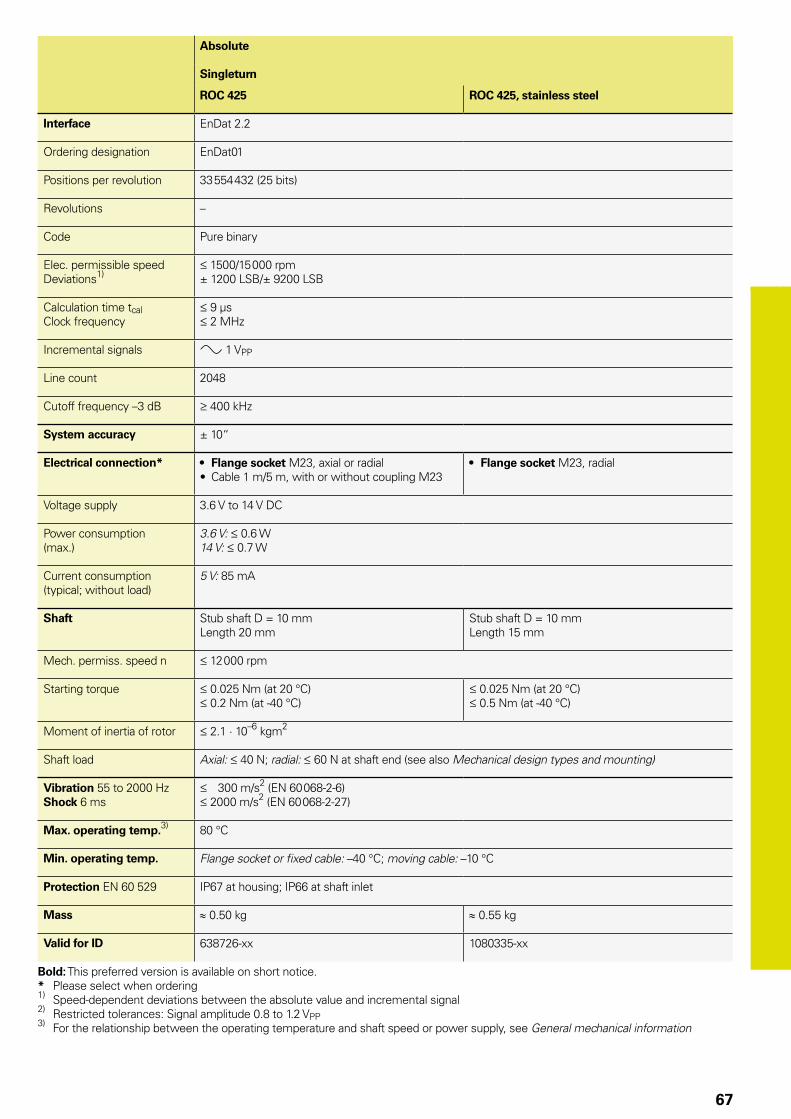
67
Absolute
Singleturn
ROC 425 ROC 425, stainless steel
Interface EnDat 2.2
Ordering designation EnDat01
Positions per revolution 33 554 432 (25 bits)
Revolutions –
Code Pure binary
Elec. permissible speedDeviations1)
1500/15 000 rpm± 1200 LSB/± 9200 LSB
Calculation time tcalClock frequency
9 µs 2 MHz
Incremental signals » 1 VPP
Line count 2048
Cutoff frequency –3 dB 400 kHz
System accuracy ± 10“
Electrical connection* • Flange socket M23, axial or radial• Cable 1 m/5 m, with or without coupling M23
• Flange socket M23, radial
Voltage supply 3.6 V to 14 V DC
Power consumption (max.)
3.6 V: 0.6 W14 V: 0.7 W
Current consumption (typical; without load)
5 V: 85 mA
Shaft Stub shaft D = 10 mm Length 20 mm
Stub shaft D = 10 mm Length 15 mm
Mech. permiss. speed n 12 000 rpm
Starting torque 0.025 Nm (at 20 °C) 0.2 Nm (at -40 °C)
0.025 Nm (at 20 °C) 0.5 Nm (at -40 °C)
Moment of inertia of rotor 2.1 · 10–6 kgm2
Shaft load Axial: 40 N; radial: 60 N at shaft end (see also Mechanical design types and mounting)
Vibration 55 to 2000 HzShock 6 ms
300 m/s2 (EN 60 068-2-6) 2000 m/s2 (EN 60 068-2-27)
Max. operating temp.3) 80 °C
Min. operating temp. Flange socket or fixed cable: –40 °C; moving cable: –10 °C
Protection EN 60 529 IP67 at housing; IP66 at shaft inlet
Mass ≈ 0.50 kg ≈ 0.55 kg
Valid for ID 638726-xx 1080335-xx
Bold: This preferred version is available on short notice.* Please select when ordering1) Speed-dependent deviations between the absolute value and incremental signal2) Restricted tolerances: Signal amplitude 0.8 to 1.2 VPP3) For the relationship between the operating temperature and shaft speed or power supply, see General mechanical information

68
ROC/ROQ/ROD 400 and RIC/RIQ 400 seriesAbsolute and incremental rotary encoders• Clamping flange• Solid shaft for separate shaft coupling
Cable radial, also usable axiallyA = Bearingb = Threaded mounting hole; the thread depth applies as of November 2012; previous depth: 5 mmm = Measuring point for operating temperature = Connector coding = ROD: Reference mark position on shaft and flange: ±15°Â = Direction of shaft rotation for output signals as per the interface description

69
Incremental
ROD 420 ROD 430 ROD 480
Interface « TTL « HTL » 1 VPP1)
Line counts* 50 100 150 200 250 360 500 512 720 –
1000 1024 1250 1500 1800 2000 2048 2500 3600 4096 5000
Reference mark One
Cutoff frequency –3 dBOutput frequencyEdge separation a
– 300 kHz 0.39 µs
180 kHz––
System accuracy 1/20 of grating period
Electrical connection* • Flange socket M23, radial and axial• Cable 1 m/5 m, with or without coupling M23
Voltage supply 5 V DC ± 0.5 V 10 V to 30 V DC 5 V ± 0.5 V DC
Current consumption without load
120 mA 150 mA 120 mA
Shaft Solid shaft D = 10 mm
Mech. permiss. speed n 16 000 rpm
Starting torque 0.01 Nm (at 20 °C)
Moment of inertia of rotor 2.3 · 10–6 kgm2
Shaft load2) Axial: 40 N; radial: 60 N at shaft end
Vibration 55 to 2000 HzShock 6 ms
300 m/s2 (EN 60 068-2-6) 2000 m/s2 (EN 60 068-2-27)
Max. operating temp.3) 100 °C (80 °C for ROD 480 with 4096 or 5000 lines)
Min. operating temp. Flange socket or fixed cable: –40 °CMoving cable: –10 °C
Protection EN 60 529 IP67 at housing; IP64 at shaft inlet (IP66 upon request)
Mass ≈ 0.3 kg
Valid for ID 376840-xx 376834-xx 376880-xx
Bold: This preferred version is available on short notice.* Please select when ordering1) Restricted tolerances: Signal amplitude: 0.8 to 1.2 VPP2) See also Mechanical design types and mounting3) For the relationship between the operating temperature and the shaft speed or power supply, see General mechanical information

70
Absolute
Singleturn Multiturn
ROC 425 ROC 413 RIC 418 ROQ 437 ROQ 425 RIQ 430
Interface* EnDat 2.2 EnDat 2.2 SSI EnDat 2.1 EnDat 2.2 EnDat 2.2 SSI EnDat 2.1
Ordering designation EnDat22 EnDat01 SSI39r1 EnDat01 EnDat22 EnDat01 SSI41r1 EnDat01
Positions per revolution 33 554 432 (25 bits) 8192 (13 bits) 262 144 (18 bits) 33 554 432 (25 bits) 8192 (13 bits) 262 144 (18 bits)
Revolutions – 4096 4096
Code Pure binary Gray Pure binary Pure binary Gray Pure binary
Elec. permissible speedDeviations1)
15 000 rpm for continuous position value
512 lines: 5000/12 000 rpm± 1 LSB/± 100 LSB2048 lines: 1500/12 000 rpm± 1 LSB/± 50 LSB
12 000 rpm± 12 LSB
4000/15 000 rpm± 400 LSB/± 800 LSB
15 000 rpm for continuous position value
512 lines: 5000/10 000 rpm± 1 LSB/± 100 LSB2048 lines: 1500/10 000 rpm± 1 LSB/± 50 LSB
12 000 rpm± 12 LSB
4000/15 000 rpm± 400 LSB/± 800 LSB
Calculation time tcalClock frequency
7 µs 8 MHz
9 µs 2 MHz
5 µs–
8 µs 2 MHz
7 µs 8 MHz
9 µs 2 MHz
5 µs–
8 µs 2 MHz
Incremental signals Without » 1 VPP2) » 1 VPP Without » 1 VPP
2) » 1 VPP
Line counts* – 512 2048 512 16 – 512 2048 512 16
Cutoff frequency –3 dB – 512 lines: 130 kHz; 2048 lines: 400 kHz 6 kHz – 512 lines: 130 kHz; 2048 lines: 400 kHz 6 kHz
System accuracy ± 20“ ± 60“ ± 480“ ± 20“ ± 60“ ± 480“
Electrical connection* • Flange socket M12, radial• Cable 1 m, with
M12 coupling
• Flange socket M23, axial or radial• Cable 1 m/5 m, with or without M23 coupling
• Flange socket M23, radial• Cable 1 m, with M23
coupling
• Flange socket M12, radial• Cable 1 m, with M12 coupling
• Flange socket M23, axial or radial• Cable 1 m/5 m, with or without M23 coupling
• Flange socket M23, radial• Cable 1 m, with M23 coupling
Voltage supply* 3.6 V to 14 V DC 3.6 V to 14 V DC 4.75 V DC to 30 V 5 V DC ± 0.25 V 3.6 V to 14 V DC 3.6 V to 14 V DC 4.75 V DC to 30 V 5 V DC ± 0.25 V
Power consumption (maximum)
3.6 V: 0.6 W14 V: 0.7 W
5 V: 0.8 W 10 V: 0.65 W30 V: 1 W
5 V: 0.9 W 3.6 V: 0.7 W14 V: 0.8 W
5 V: 0.95 W 10 V: 0.75 W30 V: 1.1 W
5 V: 1.1 W
Current consumption (typical; without load)
5 V: 85 mA 5 V: 90 mA24 V: 24 mA
5 V: 125 mA 5 V: 105 mA 5 V: 120 mA24 V: 28 mA
5 V: 150 mA
Shaft Solid shaft D = 10 mm
Mech. permiss. speed n 15 000 rpm 12 000 rpm
Starting torque 0.01 Nm (at 20 °C)
Moment of inertia of rotor 2.3 · 10–6 kgm2
Shaft load Axial: 40 N; radial: 60 N at shaft end (see also Mechanical design types and mounting)
Vibration 55 to 2000 HzShock 6 ms
300 m/s2; (EN 60 068-2-6); higher values upon requestROC/ROQ: 2000 m/s2; RIC/RIQ: 1000 m/s2 (EN 60 068-2-27)
Max. operating temp.3) 100 °C
Min. operating temp. Flange socket or fixed cable: –40 °C; moving cable: –10 °C
Protection EN 60 529 IP67 at housing; IP64 at shaft inlet3) (IP66 upon request)
Mass ≈ 0.35 kg
Valid for ID 683640-xx 1109255-xx 1131751-xx 642006-xx 683642-xx 1109257-xx 1131753-xx 642002-xx
Bold: This preferred version is available on short notice.* Please select when ordering1) Speed-dependent deviations between the absolute value and incremental signal
2) Restricted tolerances: Signal amplitude 0.8 to 1.2 VPP3) For the relationship between the operating temperature and shaft speed or power supply, see General Mechanical Information Functional safety available for ROC 425 and ROQ 437. For dimensions and specifications see Product Information

71
Absolute
Singleturn Multiturn
ROC 425 ROC 413 RIC 418 ROQ 437 ROQ 425 RIQ 430
Interface* EnDat 2.2 EnDat 2.2 SSI EnDat 2.1 EnDat 2.2 EnDat 2.2 SSI EnDat 2.1
Ordering designation EnDat22 EnDat01 SSI39r1 EnDat01 EnDat22 EnDat01 SSI41r1 EnDat01
Positions per revolution 33 554 432 (25 bits) 8192 (13 bits) 262 144 (18 bits) 33 554 432 (25 bits) 8192 (13 bits) 262 144 (18 bits)
Revolutions – 4096 4096
Code Pure binary Gray Pure binary Pure binary Gray Pure binary
Elec. permissible speedDeviations1)
15 000 rpm for continuous position value
512 lines: 5000/12 000 rpm± 1 LSB/± 100 LSB2048 lines: 1500/12 000 rpm± 1 LSB/± 50 LSB
12 000 rpm± 12 LSB
4000/15 000 rpm± 400 LSB/± 800 LSB
15 000 rpm for continuous position value
512 lines: 5000/10 000 rpm± 1 LSB/± 100 LSB2048 lines: 1500/10 000 rpm± 1 LSB/± 50 LSB
12 000 rpm± 12 LSB
4000/15 000 rpm± 400 LSB/± 800 LSB
Calculation time tcalClock frequency
7 µs 8 MHz
9 µs 2 MHz
5 µs–
8 µs 2 MHz
7 µs 8 MHz
9 µs 2 MHz
5 µs–
8 µs 2 MHz
Incremental signals Without » 1 VPP2) » 1 VPP Without » 1 VPP
2) » 1 VPP
Line counts* – 512 2048 512 16 – 512 2048 512 16
Cutoff frequency –3 dB – 512 lines: 130 kHz; 2048 lines: 400 kHz 6 kHz – 512 lines: 130 kHz; 2048 lines: 400 kHz 6 kHz
System accuracy ± 20“ ± 60“ ± 480“ ± 20“ ± 60“ ± 480“
Electrical connection* • Flange socket M12, radial• Cable 1 m, with
M12 coupling
• Flange socket M23, axial or radial• Cable 1 m/5 m, with or without M23 coupling
• Flange socket M23, radial• Cable 1 m, with M23
coupling
• Flange socket M12, radial• Cable 1 m, with M12 coupling
• Flange socket M23, axial or radial• Cable 1 m/5 m, with or without M23 coupling
• Flange socket M23, radial• Cable 1 m, with M23 coupling
Voltage supply* 3.6 V to 14 V DC 3.6 V to 14 V DC 4.75 V DC to 30 V 5 V DC ± 0.25 V 3.6 V to 14 V DC 3.6 V to 14 V DC 4.75 V DC to 30 V 5 V DC ± 0.25 V
Power consumption (maximum)
3.6 V: 0.6 W14 V: 0.7 W
5 V: 0.8 W 10 V: 0.65 W30 V: 1 W
5 V: 0.9 W 3.6 V: 0.7 W14 V: 0.8 W
5 V: 0.95 W 10 V: 0.75 W30 V: 1.1 W
5 V: 1.1 W
Current consumption (typical; without load)
5 V: 85 mA 5 V: 90 mA24 V: 24 mA
5 V: 125 mA 5 V: 105 mA 5 V: 120 mA24 V: 28 mA
5 V: 150 mA
Shaft Solid shaft D = 10 mm
Mech. permiss. speed n 15 000 rpm 12 000 rpm
Starting torque 0.01 Nm (at 20 °C)
Moment of inertia of rotor 2.3 · 10–6 kgm2
Shaft load Axial: 40 N; radial: 60 N at shaft end (see also Mechanical design types and mounting)
Vibration 55 to 2000 HzShock 6 ms
300 m/s2; (EN 60 068-2-6); higher values upon requestROC/ROQ: 2000 m/s2; RIC/RIQ: 1000 m/s2 (EN 60 068-2-27)
Max. operating temp.3) 100 °C
Min. operating temp. Flange socket or fixed cable: –40 °C; moving cable: –10 °C
Protection EN 60 529 IP67 at housing; IP64 at shaft inlet3) (IP66 upon request)
Mass ≈ 0.35 kg
Valid for ID 683640-xx 1109255-xx 1131751-xx 642006-xx 683642-xx 1109257-xx 1131753-xx 642002-xx
Bold: This preferred version is available on short notice.* Please select when ordering1) Speed-dependent deviations between the absolute value and incremental signal
2) Restricted tolerances: Signal amplitude 0.8 to 1.2 VPP3) For the relationship between the operating temperature and shaft speed or power supply, see General Mechanical Information Functional safety available for ROC 425 and ROQ 437. For dimensions and specifications see Product Information
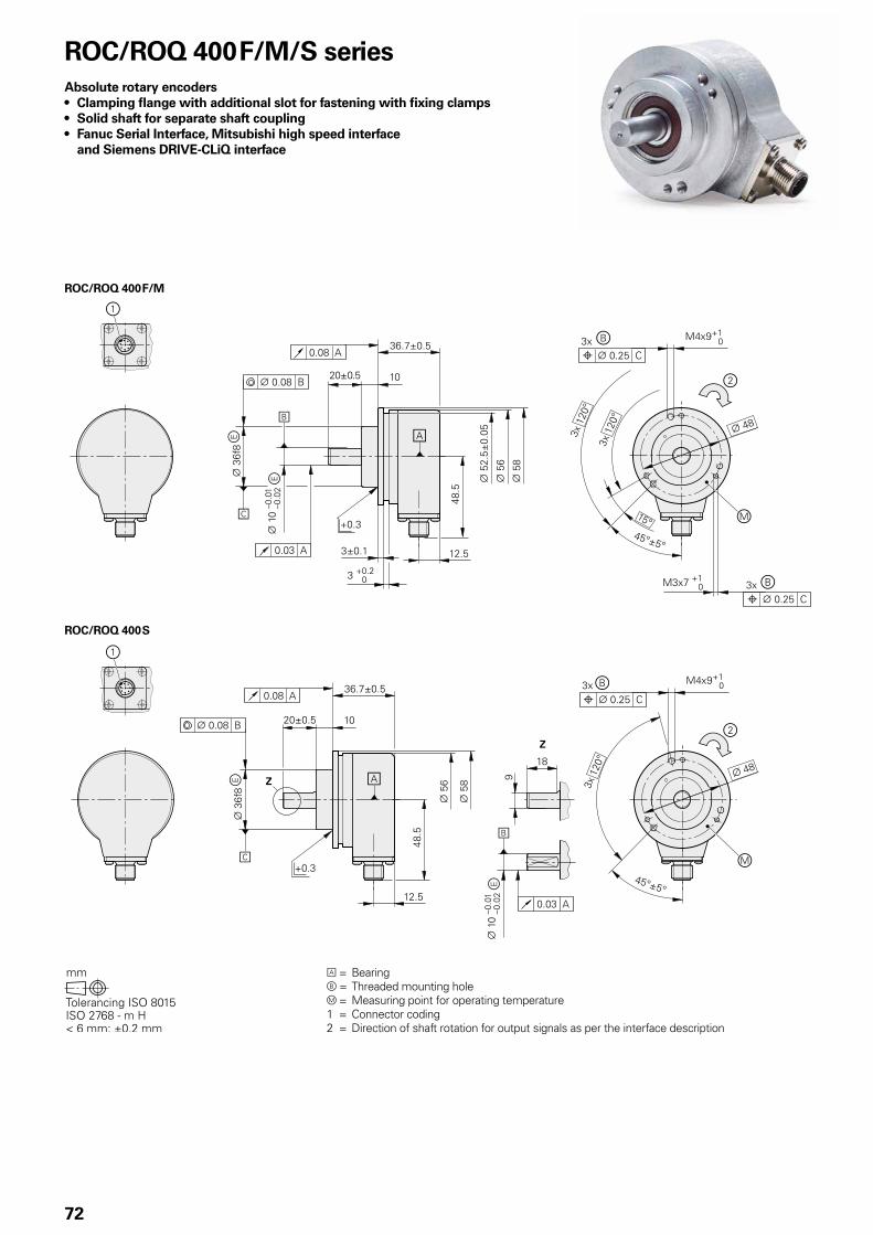
ROC/ROQ 400 F/M
ROC/ROQ 400 S
72
A = Bearingb = Threaded mounting holem = Measuring point for operating temperature1 = Connector coding2 = Direction of shaft rotation for output signals as per the interface description
ROC/ROQ 400 F/M/S seriesAbsolute rotary encoders• Clamping flange with additional slot for fastening with fixing clamps• Solid shaft for separate shaft coupling• Fanuc Serial Interface, Mitsubishi high speed interface
and Siemens DRIVE-CLiQ interface

73
Absolute
Singleturn Multiturn
ROC 425 F ROC 425 M ROC 424 S ROQ 437 F ROQ 435 M ROQ 436 S
Interface Fanuc Serial Interface; i Interface
Mitsubishi high speed interface
DRIVE-CLiQ Fanuc Serial Interface; i Interface
Mitsubishi high speed interface
DRIVE-CLiQ
Ordering designation Fanuc05 Mit03-4 DQ01 Fanuc05 Mit03-4 DQ01
Positions per revolution i: 33 554 432 (25 bits)
: 8 388 608 (23 bits)
33 554 432 (25 bits)
16 777 216 (24 bits)
33 554 432 (25 bits)
8 388 608 (23 bits)
16 777 216
Revolutions 8192 via revolution counter
– i: 4096: 2048
4096 4096
Code Pure binary
Elec. permissible speed 15 000 rpm for continuous position value
Calculation time tcal 5 µs – 8 µs 5 µs – 8 µs
Incremental signals Without
System accuracy ± 20“
Electrical connection Flange socket M12, radial
Cable length 30 m 95 m2) 30 m 95 m2)
DC voltage supply 3.6 to 14 V 10 V to 36 V 3.6 to 14 V 10 V to 36 V
Power consumption (max.) 5 V: 0.7 W14 V: 0.8 W
10 V: 1.4 W36 V: 1.5 W
5 V: 0.75 W14 V: 0.85 W
10 V: 1.4 W36 V: 1.5 W
Current consumption (typical; without load)
5 V: 90 mA 24 V: 37 mA 5 V: 100 mA 24 V: 43 mA
Shaft Stub shaft D = 10 mm (for ROC 424 S and ROQ 436 S with flat
Mech. permiss. speed n1) 15 000 rpm 12 000 rpm
Starting torque 0.01 Nm (at 20 °C)
Moment of inertia of rotor 2.9 · 10–6 kgm2
Shaft load Axial: 40 N radial: 60 N at shaft end (see also Mechanical Design Types and Mounting)
Vibration 55 to 2000 HzShock 6 ms
300 m/s2 (EN 60 068-2-6) 2000 m/s2 (EN 60 068-2-27)
Max. operating temp. 1) 100 °C
Min. operating temp. –30 °C
Protection EN 60 529 IP67 at housing; IP64 at shaft inlet
Mass ≈ 0.35 kg
Valid for ID 1081306-xx 1096727-xx 1036790-xx 1081304-xx 1096729-xx 1036792-xx
1) For the relationship between the operating temperature and the shaft speed or supply voltage, see General Mechanical Information2) See the brochure Interfaces of HEIDENHAIN Encoders; with nMG=1 (incl. adapter cable) Functional safety for ROC 424 S and ROQ 436 S available, For dimensions and specifications see Product Information

80
74
ROC/ROQ 400 seriesAbsolute rotary encoders • Clamping flange • Solid shaft for separate shaft coupling• Fieldbus interface
A = Bearingb = Threaded mounting hole; the thread depth applies as of November 2012; previous depth: 5 mm = Direction of shaft rotation for output signals as per the interface description

75
Absolute
Singleturn Multiturn
ROC 413 ROQ 425
Interface* PROFIBUS-DP1) PROFINET IO PROFIBUS-DP1) PROFINET IO
Positions per revolution 8192 (13 bits)2)
Revolutions – 40962)
Code Pure binary
Elec. permissible speed 12 000 rpm for continuous position value 10 000 rpm for continuous position value
Incremental signals Without
System accuracy ± 60“
Electrical connection* M16 cable gland4) Three flange sockets M12, radial
M16 cable gland4) Three flange sockets M12, radial
Voltage supply 9 V to 36 V DC 10 V to 30 V DC 9 V to 36 V DC 10 V to 30 V DC
Power consumption (max.) 9 V: 3.38 W36 V: 3.84 W
Current consumption (typical; without load)
24 V: 125 mA
Shaft Solid shaft D = 10 mm
Mech. permiss. speed n 12 000 rpm
Starting torque 0.01 Nm (at 20 °C)
Moment of inertia of rotor 2.3 · 10–6 kgm2
Shaft load Axial: 40 N; radial: 60 N at shaft end (see also Mechanical design types and mounting)
Vibration 55 to 2000 HzShock 6 ms
100 m/s2 (EN 60 068-2-6); higher values upon request 2000 m/s1 (EN 60 068-2-27)
Max. operating temp.3) 70 °C
Min. operating temp. –40 °C
Protection EN 60 529 IP67 at housing; IP64 at shaft inlet3) (IP66 upon request)
Mass ≈ 0.35 kg
Valid for ID 549886-xx 725519-xx 549888-xx 725521-xx
Bold: This preferred version is available on short notice.* Please select when ordering1) Supported profiles: DP-V0, DP-V1, DP-V22) Programmable3) For the relationship between the operating temperature and shaft speed or power supply, see General mechanical information4) Variants with three M12 flange sockets upon request
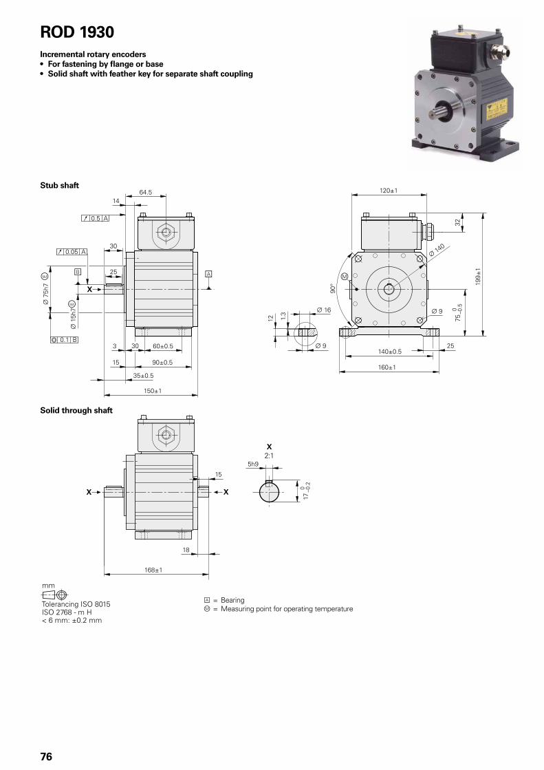
76
ROD 1930Incremental rotary encoders • For fastening by flange or base• Solid shaft with feather key for separate shaft coupling
A = Bearingm = Measuring point for operating temperature
Stub shaft
Solid through shaft

77
Incremental
ROD 1930
Interface* « HTL « HTLs
Line counts* 600 1024 1200 2400
Reference mark Without One
Output frequencyEdge separation a
160 kHz 0.76 µs
System accuracy ± 1/10 of grating period
Electrical connection Terminal box with screw terminals
Voltage supply 10 V to 30 V DC
Current consumption (typical; without load)
15 V: 60 mA
Shaft* Stub shaft or solid through shaft, D = 15 mm with feather key
Mech. permissible speed 4000 rpm
Starting torque at 20° C
Solid shaft: 0.05 NmThrough shaft: 0.15 Nm
Moment of inertia of rotor 2.5 · 10-5 kgm2
Permissible angular acceleration
4 x 10⁴ rad/s2
Shaft load1) Axial: 150 NRadial: 200 N at shaft end
Vibration 25 to 200 HzShock 6 ms
100 m/s2 (EN 60 068-2-6) 2000 m/s1 (EN 60 068-2-27)
Operating temperature2) –20 °C to +70 °C
Protection EN 60 529 IP66
Mass ≈ 4.5 kg
Valid for ID Stub shaft: 1043373-xxThrough shaft: 1043377-xx
* Please select when ordering1) See also Mechanical Design Types and Mounting2) Special versions upon request, e.g.with water jacket

78
HR 1120Electronic handwheel• Version for integration• With mechanical detent
= Cutout for mounting = Direction of rotation for output
signals as per the interface description

79
Incremental
HR 1120
Interface « TTL
Line count 100
Output frequency 5 kHz
Switching times t+ / t– 100 ns
Electrical connection Via M3 screw terminals
Cable length 30 m
Voltage supply 5 V DC ± 0.25 V
Current consumption without load
160 mA
Detent Mechanical100 detent positions per revolutionDetent position within the low level of Ua1 and Ua2
Mech. permissible speed 200 rpm
Torque 0.1 Nm (at 25 °C)
Vibration (10 to 200 Hz) 20 m/s2
Max. operating temp. 60 °C
Min. operating temp. 0 °C
Protection (EN 60 529) IP00; IP40 when mountedNo condensation permitted
Mass ≈ 0.18 kg
Valid for ID 687617-xx
Mounting informationThe HR 1120 is designed for mounting in a panel. CE compliance of the complete system must be ensured by taking the correct measures during installation.

80
Pin layout12-pin coupling, M23 12-pin connector, M23
Voltage supply Incremental signals Other signals
12 2 10 11 5 6 8 1 3 4 9 7 /
UP Sensor1)
UP
0 V Sensor1)
0 VA+ A– B+ B– R+ R– Vacant Vacant Vacant
Brown/Green
Blue White/Green
White Brown Green Gray Pink Red Black / Violet Yellow
Cable shield connected to housing; UP = Power supply voltageSensor: The sensor line is connected in the encoder with the corresponding power line.Vacant pins or wires must not be used!1) LIDA 2xx: Vacant
Signal period360° elec.
(rated value)
A, B, R measured with oscilloscope in differential mode
HEIDENHAIN encoders with » 1 VPP interface provide voltage signals that can be highly interpolated.
The sinusoidal incremental signals A and B are phase-shifted by 90° elec. and have amplitudes of typically 1 VPP. The illustrated sequence of output signals—with B lagging A—applies for the direction of motion shown in the dimension drawing.
The reference mark signal R has an unambiguous assignment to the incremental signals. The output signal might be somewhat lower next to the reference mark.
Alternative signal shapeThe Interfaces of HEIDENHAIN
Encoders brochure, ID 1078628-xx, includes comprehensive descriptions of all available interfaces as well as general electrical information.
InterfacesIncremental signals » 1 VPP

81
Incremental signals « TTL
HEIDENHAIN encoders with « TTL interface incorporate electronics that digitize sinusoidal scanning signals with or without interpolation.
The incremental signals are transmitted as the square-wave pulse trains Ua1 and Ua2, phase-shifted by 90° elec. The reference mark signal consists of one or more reference pulses Ua0, which are gated with the incremental signals. In addition, the integrated electronics produce their inverse signals ¢, £ and ¤ for noise-proof transmission. The illustrated sequence of output signals—with Ua2 lagging Ua1—applies to the direction of motion shown in the dimension drawing.
The fault detection signal ¥ indicates fault conditions such as an interruption in the supply lines, failure of the light source, etc.
Signal period 360° elec. Fault
Measuring step after 4-fold evaluation
The inverse signals ¢, £, ¤ are not shown.
The Interfaces of HEIDENHAIN Encoders brochure, ID 1078628-xx, provides comprehensive descriptions of all available interfaces as well as general electrical information.
ERN, ROD pin layout12-pin flange socket or coupling, M23
12-pin connector, M23
Voltage supply Incremental signals Other signals
12 2 10 11 5 6 8 1 3 4 7 / 9
UP SensorUP
0 V Sensor0 V
Ua1 ¢ Ua2 £ Ua0 ¤ ¥1) Vacant Vacant2)
Brown/Green
Blue White/Green
White Brown Green Gray Pink Red Black Violet – Yellow
Shield on housing; UP = Power supply voltageSensor: The sensor line is connected in the encoder with the corresponding power line.1) ERO 14xx: free 2) Exposed linear encoders: TTL/11 µAPP switchover for PWT
HR pin layoutScrew-terminal connection
Voltage supply Incremental signals
Connection + – A A B B
Signal UP5 V
UN0 V
Ua1 ¢ Ua2 £
A shielded cable with a cross section of at least 0.5 mm2 is recommended when connecting the handwheel to the voltage supply.
The handwheel is connected electrically via screw terminals. The appropriate wire end sleeves must be attached to the wires.
The distance between two successive edges of the incremental signals Ua1 and Ua2 through 1-fold, 2-fold or 4-fold evaluation is one measuring step.
Ele
ctri
cal c
on
nec
tio
n

82
Incremental signals « HTL, HTLs
HEIDENHAIN encoders with « HTL interface incorporate electronics that digitize sinusoidal scanning signals with or without interpolation.
The incremental signals are transmitted as the square-wave pulse trains Ua1 and Ua2, phase-shifted by 90° elec. The reference mark signal consists of one or more reference pulses Ua0, which are gated with the incremental signals. In addition, the integrated electronics produce their inverted signals ¢, £ and ¤ for noise-proof transmission (does not apply to HTLs). The illustrated sequence of output signals—with Ua2 lagging Ua1—applies to the direction of motion shown in the dimension drawing.
The fault detection signal ¥ indicates fault conditions, for example a failure of the light source.
Signal period 360° elec. Fault
Measuring step after 4-fold evaluation
The inverse signals ¢, £, ¤ are not shown.
The distance between two successive edges of the incremental signals Ua1 and Ua2 through 1-fold, 2-fold or 4-fold evaluation is one measuring step.
Comprehensive descriptions of all available interfaces as well as general electrical information are included in the Interfaces catalog ID 1078628-xx.
Power and current consumption
For encoders with a large supply voltage range, the current consumption has a nonlinear relationship with the supply voltage. It is determined using the calculation described in the Interfaces of HEIDENHAIN Encoders catalog.
For the rotary encoders with additional HTL output signals, the power consumption also depends on the output frequency and the cable length. The power consumption values for the HTL or HTLs interface can therefore be taken from the diagrams.
The maximum permissible output fre-quency is shown in the specifications. It occurs at the maximum permissible shaft speed. The output frequency for any shaft speed is calculated using the following formula:
f = (n/60) · z · 10–3
With f = Output frequency in kHzn = Shaft speed in rpm
z = Number of signal periods per 360°
Power consumption (maximum) for HTL interface and supply voltage UP = 30 V
Power consumption (maximum) for HTLs interface and supply voltage UP = 30 V
Output frequency in kHz
Output frequency in kHz
Po
wer
co
nsu
mp
tio
n in
mW
Pow
er c
on
sum
pti
on
in m
W

83
Cable length for HTL
For the rotary encoders with additional HTL output signals, the maximum permissible cable length depends on several criteria:• Output frequency• Supply voltage• Operating temperature
The relationships are shown separately for the HTL and HTLs interface in the diagrams. There are no limitations if a supply voltage of 10 V DC is used.
Maximum permissible cable length for HTL interface
Maximum permissible cable length for HTLs interface
Output frequency in kHz
Output frequency in kHz
C
able
len
gth
in m
Cab
le le
ng
th in
m

84
Pin layout12-pin flange socket or coupling, M23
Voltage supply Incremental signals Other signals
12 2 10 11 5 6 8 1 3 4 7 / 9
HTL UP SensorUP
0 V Sensor0 V
Ua1 ¢ Ua2 £ Ua0 ¤ ¥ Vacant Vacant
HTLs 0 V 0 V 0 V
Brown/Green
Blue White/Green
White Brown Green Gray Pink Red Black Violet / Yellow
Shield on housing; UP = Power supply voltageSensor: The sensor line is connected in the encoder with the corresponding power line.
Screw-terminal connection A shielded cable with a cross section of at least 0.5 mm2 is recommended when connecting to the voltage supply.
The encoder is connected through screw terminals. The appropriate wire end sleeves must be attached to the wires.
Voltage supply Incremental signals
Connection 1 2 3 4 5 6
HTL UP UN0V
Ua1 ¢ Ua2 £
HTLs Ua2 0 V Ua0
ROD 1930 pin layout

85
17-pin coupling, M23
Power supply Incremental signals1) Position values
7 1 10 4 11 15 16 12 13 14 17 8 9
UP SensorUP
0 V Sensor0 V
Internal shield
A+ A– B+ B– DATA DATA CLOCK CLOCK
Brown/Green
Blue White/Green
White / Green/Black
Yellow/Black
Blue/Black
Red/Black
Gray Pink Violet Yellow
Cable shield connected to housing; UP = Power supply voltageSensor: The sensor line is connected in the encoder with the corresponding power line.Vacant pins or wires must not be used!1) Only with ordering designations EnDat01 and EnDat02
Position values
The EnDat interface is a digital, bidirectional interface for encoders. It is capable of transmitting position values as well as transmitting or updating information stored in the encoder, or saving new information. Thanks to the serial transmission method, only four signal lines are required. The DATA is transmitted in synchronism with the CLOCK signal from the subsequent electronics. The type of transmission (position values, parameters, diagnostics, etc.) is selected through mode commands that the subsequent electronics send to the encoder. Some functions are available only with EnDat 2.2 mode commands.
Ordering designation Command set Incremental signals
EnDat01EnDatHEnDatT
EnDat 2.1 or EnDat 2.2
1 VPPHTLTTL
EnDat21 –
EnDat02 EnDat 2.2 1 VPP
EnDat22 EnDat 2.2 –
Versions of the EnDat interface
Absolute encoder Subsequent electronics
A/Ua1*)
B/Ua2*)
Operating parameters
Operating condition
Parameters of the OEM
Parameters of the encoder manufacturer for
EnDat 2.1 EnDat 2.2
*) Depends on encoder 1 VPP, HTL or TTL
Absolute position value En
Dat
inte
rfac
e
Incremental signals *)
Comprehensive descriptions of all available interfaces as well as general electrical information are included in the Interfaces for HEIDENHAIN Encoders brochure, ID 1078628-xx.
Pin layout8-pin coupling, M12
Power supply Position values
8 2 5 1 3 4 7 6
UP Sensor UP 0 V Sensor 0 V DATA DATA CLOCK CLOCK
Brown/Green Blue White/Green White Gray Pink Violet Yellow
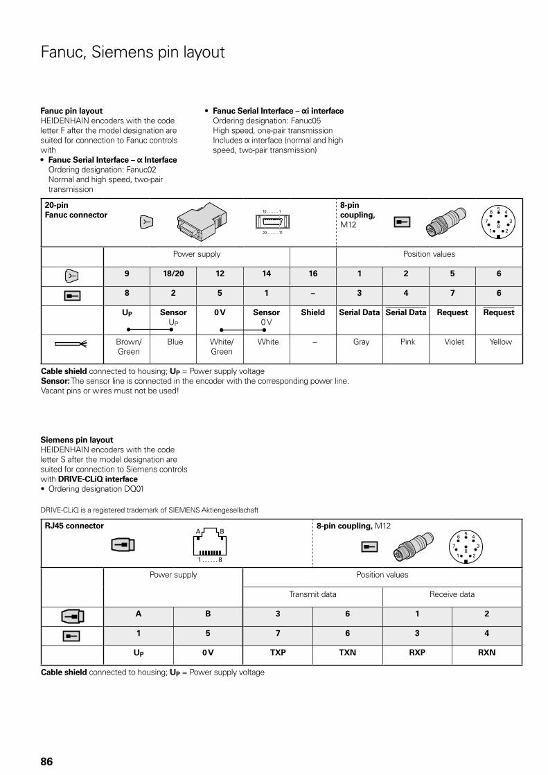
86
20-pin Fanuc connector
8-pin coupling, M12
Power supply Position values
9 18/20 12 14 16 1 2 5 6
8 2 5 1 – 3 4 7 6
UP SensorUP
0 V Sensor0 V
Shield Serial Data Serial Data Request Request
Brown/Green
Blue White/Green
White – Gray Pink Violet Yellow
Cable shield connected to housing; UP = Power supply voltageSensor: The sensor line is connected in the encoder with the corresponding power line.Vacant pins or wires must not be used!
Fanuc pin layoutHEIDENHAIN encoders with the code letter F after the model designation are suited for connection to Fanuc controls with• Fanuc Serial Interface – Interface
Ordering designation: Fanuc02 Normal and high speed, two-pair transmission
Fanuc, Siemens pin layout
• Fanuc Serial Interface – i interface Ordering designation: Fanuc05 High speed, one-pair transmission Includes interface (normal and high speed, two-pair transmission)
RJ45 connector 8-pin coupling, M12
Power supply Position values
Transmit data Receive data
A B 3 6 1 2
1 5 7 6 3 4
UP 0 V TXP TXN RXP RXN
Cable shield connected to housing; UP = Power supply voltage
Siemens pin layoutHEIDENHAIN encoders with the code letter S after the model designation are suited for connection to Siemens controls with DRIVE-CLiQ interface• Ordering designation DQ01
DRIVE-CLiQ is a registered trademark of SIEMENS Aktiengesellschaft
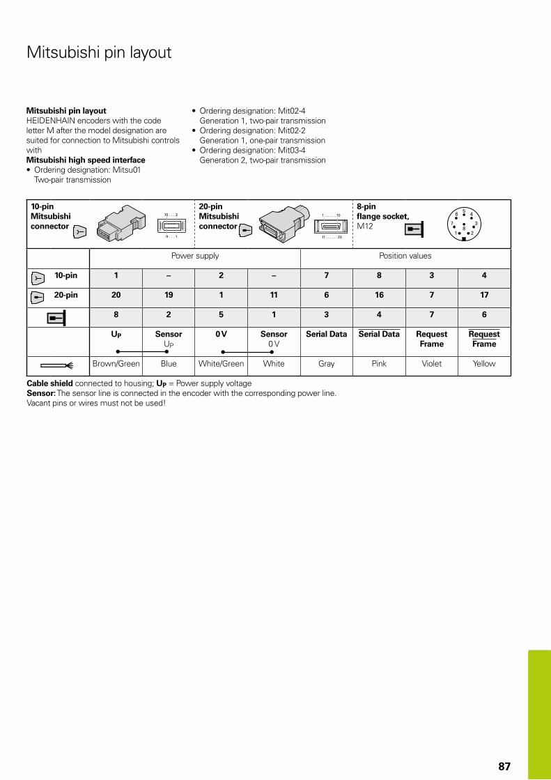
87
Mitsubishi pin layout
Mitsubishi pin layoutHEIDENHAIN encoders with the code letter M after the model designation are suited for connection to Mitsubishi controls withMitsubishi high speed interface• Ordering designation: Mitsu01
Two-pair transmission
10-pin Mitsubishi connector
20-pin Mitsubishi connector
8-pin flange socket, M12
Power supply Position values
10-pin 1 – 2 – 7 8 3 4
20-pin 20 19 1 11 6 16 7 17
8 2 5 1 3 4 7 6
UP SensorUP
0 V Sensor0 V
Serial Data Serial Data RequestFrame
RequestFrame
Brown/Green Blue White/Green White Gray Pink Violet Yellow
Cable shield connected to housing; UP = Power supply voltageSensor: The sensor line is connected in the encoder with the corresponding power line.Vacant pins or wires must not be used!
• Ordering designation: Mit02-4 Generation 1, two-pair transmission
• Ordering designation: Mit02-2 Generation 1, one-pair transmission
• Ordering designation: Mit03-4 Generation 2, two-pair transmission

88
PROFIBUS-DP position values
PROFIBUS-DPThe PROFIBUS is a non-proprietary, open fieldbus according to the international standard EN 50 170. The connecting of sensors through fieldbus systems min-imizes the cost of cabling and reduces the number of lines between encoder and subsequent electronics.
PROFIBUS-DP profileThe PNO (PROFIBUS user organization) has defined standard, nonproprietary profiles for the connection of absolute encoders to the PROFIBUS-DP. This ensures high flexibility and simple configuration on all systems that use these standardized profiles.
Encoders with PROFIBUS-DPThe absolute rotary encoders with integrated PROFIBUS-DP interface are connected directly to the PROFIBUS.
AccessoriesAdapter M12 (male), 4-pin, B-codedFits 5-pin bus output, with PROFIBUS terminating resistor.
Required for last participant if the encoder’s internal terminating resistor is not to be used.ID 584217-01
Mating connectors are required for connection via M12 connecting element:Bus inputM12 connector (female), 5-pin, B-codedBus outputM12 coupling (male), 5-pin, B-codedVoltage supplyM12 connector, 4-pin, A-coded
Addressing of ones digit
Voltage supply
Bus input
Bus output
Addressing of tens digit
Pin layout of M12 connecting elementMating connector:Bus input, 5-pin connector (female)M12 B-coded
Mating connector:Bus output, 5-pin coupling (male)M12 B-coded
Power supply Position values
1 3 5 housing 2 4
BUS in / / Shield Shield DATA (A) DATA (B)
BUS out U1) 0 V1) Shield Shield DATA (A) DATA (B)
1)For supplying the external terminal resistor
Mating connector:Voltage supply, 4-pin connector (female)M12 A-coded
1 3 2 4
UP 0 V Vacant Vacant
Terminating resistor
Connection via M12 connecting element
Connection via M16 cable gland
The Interfaces of HEIDENHAIN Encoders brochure, ID 1078628-xx, provides comprehensive descriptions of all available interfaces as well as general electrical information.
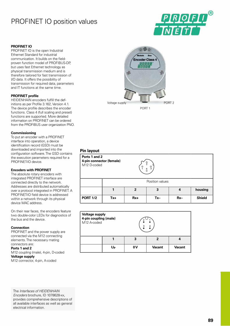
89
PROFINET IO position values
PROFINET IOPROFINET IO is the open Industrial Ethernet Standard for industrial communication. It builds on the field-proven function model of PROFIBUS-DP, but uses fast Ethernet technology as physical transmission medium and is therefore tailored for fast transmission of I/O data. It offers the possibility of transmission for required data, parameters and IT functions at the same time.
PROFINET profileHEIDENHAIN encoders fulfill the def-initions as per Profile 3.162, Version 4.1. The device profile describes the encoder functions. Class 4 (full scaling and preset) functions are supported. More detailed information on PROFINET can be ordered from the PROFIBUS user organization PNO.
CommissioningTo put an encoder with a PROFINET interface into operation, a device identification record (GSD) must be downloaded and imported into the configuration software. The GSD contains the execution parameters required for a PROFINET-IO device.
Encoders with PROFINETThe absolute rotary encoders with integrated PROFINET interface are connected directly to the network. Addresses are distributed automatically over a protocol integrated in PROFINET. A PROFINET-IO field device is addressed within a network through its physical device MAC address.
On their rear faces, the encoders feature two double-color LEDs for diagnostics of the bus and the device.
ConnectionPROFINET and the power supply are connected via the M12 connecting elements. The necessary mating connectors are:Ports 1 and 2M12 coupling (male), 4-pin, D-codedVoltage supplyM12 connector, 4-pin, A-coded
Voltage supply
PORT 1
PORT 2
Pin layoutPorts 1 and 24-pin connector (female)M12 D-coded
Position values
1 2 3 4 housing
PORT 1/2 Tx+ Rx+ Tx– Rx– Shield
Voltage supply 4-pin coupling (male)M12 A-coded
1 3 2 4
UP 0 V Vacant Vacant
The Interfaces of HEIDENHAIN Encoders brochure, ID 1078628-xx, provides comprehensive descriptions of all available interfaces as well as general electrical information.

90
SSI position values
Data transfer
T = 1 to 10 µstcal See Specificationst1 0.4 µs
(w/o cable)t2 = 17 to 20 µstR 5 µsn = Data word length
13 bits for ECN/ROC 25 bits for EQN/ROQ
CLOCK and DATA not shown
The position value beginning with the Most Significant Bit (MSB first) is transferred on the DATA lines in synchronism with a CLOCK signal transmitted by the control. The SSI standard data word length for singleturn encoders is 13 bits, and for multiturn encoders 25 bits. In addition to the absolute position values, incremental signals can also be transmitted. For a description of the signals, see 1 VPP incremental signals.
The following functions can be activated through programming inputs:• Direction of rotation• Zero reset (setting to zero)
Pin layout17-pin coupling, M23
Voltage supply Incremental signals Position values Other signals
7 1 10 4 11 15 16 12 13 14 17 8 9 2 5
UP SensorUP
0 V Sensor0 V
Internal shield
A+ A– B+ B– DATA DATA CLOCK CLOCK Direc-tion of rota-tion1)
Zero reset1)
Brown/Green
Blue White/Green
White / Green/Black
Yellow/Black
Blue/Black
Red/Black
Gray Pink Violet Yellow Black Green
Shield on housing; UP = Power supply voltageSensor: With a 5 V supply voltage, the sensor line is connected in the encoder with the corresponding power line.1) Vacant on ECN/EQN 10xx and ROC/ROQ 10xx
Comprehensive descriptions of all available interfaces as well as general electrical information are included in the Interfaces catalog ID 1078628-xx.

M23
M23
M23
M23
M12
M12
M23
91
The pins on connectors are numbered in the direction opposite to those on couplings or flange sockets, regardless of whether the connecting elements have
male contacts or
female contacts.
When engaged, the connections provide protection to IP67 (D-sub connector: IP50; EN 60 529). When not engaged, there is no protection.
Connecting elements and cablesGeneral information
Connector (insulated): Connecting element with coupling ring; available with male or female contacts (see symbols).
Symbols
Coupling (insulated): Connecting element with external thread; available with male or female contacts (see symbols).
Symbols
D-sub connector for HEIDENHAIN controls, counters and IK absolute value cards.
Symbols
Accessory for flange sockets and M23 mounted couplings
Threaded metal dust capID 219926-01
Accessory for M12 connecting elementInsulation spacerID 596495-01
Mounted coupling with central fastening
Mounted coupling with flange
1) Interface electronics are integrated in the connector
Cutout for mounting
M12 right-angle connector
Flange socket: with external thread; permanently mounted on a housing, available with male or female contacts.
Symbols
M12 flange socket with motor-internal encoder cable
k = Mating mounting holes1 = At least 4 mm of load-bearing thread length

92
» 1 VPP « TTL « HTL
PUR connecting cables 12-pin: [4(2 × 0.14 mm2) + (4 × 0.5 mm2)]; AP = 0.5 mm2 ¬ 8 mm
Complete with connector (female) and coupling (male)
298401-xx
Complete with connectors (female and male)
298399-xx
Complete with connector (female) and D-sub connector (female), 15-pin, for TNC
310199-xx
Complete with connector (female) and D-sub connector (male), 15-pin, for PWM 20/EIB 74x
310196-xx
With one connector (female)
309777-xx
Cable without connectors, ¬ 8 mm 816317-xx
Mating element on connecting cable to connector on encoder cable
Connector (female) for cable ¬ 8 mm 291697-05
Connector on connecting cable for connection to subsequent electronics
Connector (male) for cable ¬ 8 mm ¬ 6 mm
291697-08291697-07
Coupling on connecting cable Coupling (male) for cable ¬ 4.5 mm ¬ 6 mm ¬ 8 mm
291698-14291698-03291698-04
Flange socket for mounting on subsequent electronics
Flange socket (female) 315892-08
Mounted couplings
With flange (female) ¬ 6 mm ¬ 8 mm
291698-17291698-07
With flange (male) ¬ 6 mm ¬ 8 mm
291698-08291698-31
With central fastening ¬ 6 mm to 10 mm(male)
741045-01
Adapter connector » 1 VPP/11 µAPPFor converting the 1 VPP signals to 11 µAPP; M23 connector (female, 12-pin) and M23 connector (male, 9-pin)
364914-01
AP: Cross section of power supply lines
Connecting cables 1 VPP, TTL, HTL 12-pin M23

93
EnDat without incremental signals
EnDat with incremental signals SSI
PUR connecting cables 8-pin: [(4 × 0.14 mm2) + (4 × 0.34 mm2)]; AP = 0.34 mm2
17-pin: [(4 × 0.14 mm2) + 4(2 × 0.14 mm2) + (4 × 0.5 mm2)]; AP = 0.5 mm2
Cable diameter 6 mm 3.7 mm 8 mm
Complete with connector (female) and coupling (male)
368330-xx 801142-xx 323897-xx340302-xx
Complete with right-angle connector (female) and coupling (male)
373289-xx 801149-xx –
Complete with connector (female) and D-sub connector (female), 15-pin, for TNC (position inputs)
533627-xx – 332115-xx
Complete with connector (female) and D-sub connector (female), 25-pin, for TNC (rotational speed inputs)
641926-xx – 336376-xx
Complete with connector (female) and D-sub connector (male), 15-pin, for IK 215, PWM 20, EIB 74x, etc.
524599-xx 801129-xx 324544-xx
Complete with right-angle connector (female) and D-sub connector (male), 15-pin, for IK 215, PWM 20, EIB 74x, etc.
722025-xx 801140-xx –
With one connector (female)
634265-xx – 309778-xx 309779-xx1)
With one right-angle connector (female)
606317-xx – –
Cable only – – 816322-xx
Italics: Cable with assignment for “speed encoder” input (MotEnc EnDat)1) Without incremental signalsAP: Cross section of power supply lines
EnDat connecting cables 8-pin 17-pin M12 M23

94
Connecting cables Fanuc
Mitsubishi Siemens
Cable Fanuc Mitsubishi
PUR connecting cable for M23 connecting elements
CompleteWith 17-pin M23 connector (female)and Fanuc connector[(2 x 2 x 0.14 mm2) + (4 x 1 mm2)];AP = 1 mm2
¬ 8 mm 534855-xx –
CompleteWith 17-pin M23 connector (female) and20-pin Mitsubishi connector[(2 x 2 x 0.14 mm2) + (4 x 0.5 mm2)];AP = 0.5 mm2
¬ 6 mm – 367958-xx
CompleteWith 17-pin M23 connector (female) and10-pin Mitsubishi connector[(2 x 2 x 0.14 mm2) + (4 x 1 mm2)];AP = 1 mm2
¬ 8 mm – 573661-xx
Cable only[(2 x 2 x 0.14 mm2) + (4 x 1 mm2)];AP = 1 mm2
¬ 8 mm 816327-xx
10-pin
20-pin
Cable Fanuc Mitsubishi
PUR connecting cable for M12 connecting element [(1 x 4 x 0.14 mm2) + (4 x 0.34 mm2)]; AP = 0.34 mm2
CompleteWith 8-pin M12 connector (female)and Fanuc connector
¬ 6 mm 646807-xx –
CompleteWith 8-pin M12 connector (female) and20-pin Mitsubishi connector
¬ 6 mm – 646806-xx
CompleteWith 8-pin M12 connector (female) and10-pin Mitsubishi connector
¬ 6 mm – 647314-xx
10-pin
20-pin
Cable Siemens
PUR connecting cable for M12 connecting element [2(2 x 0.17 mm2) + (2 x 0.24 mm2)]; AP = 0.24 mm2
CompleteWith 8-pin M12 connector (female) and 8-pin M12 coupling (male)
¬ 6.8 mm 822504-xx
CompleteWith 8-pin M12 connector (female) and Siemens RJ45 connector (IP67) Cable length: 1 m
¬ 6.8 mm 1094652-01
CompleteWith 8-pin M12 connector (female) and Siemens RJ45 connector (IP20)
¬ 6.8 mm 1093042-xx
AP: Cross section of power supply lines

95
Interface electronics
Interface electronics from HEIDENHAIN adapt the encoder signals to the interface of the subsequent electronics. They are used when the subsequent electronics cannot directly process the output signals from HEIDENHAIN encoders, or if additional interpolation of the signals is necessary.
Box design
Plug design
Version for integration
Top-hat rail design
Input signals of the interface electronicsInterface electronics from HEIDENHAIN can be connected to encoders with sinusoidal signals of 1 VPP (voltage signals) or 11 µAPP (current signals). Encoders with the serial interfaces EnDat or SSI can also be connected to various interface electronics.
Output signals of the interface electronicsInterface electronics with the following interfaces to the subsequent electronics are available:• TTL square-wave pulse trains• EnDat 2.2• DRIVE-CLiQ• Fanuc Serial Interface• Mitsubishi high speed interface• Yaskawa Serial Interface• Profibus
Interpolation of the sinusoidal input signalsIn addition to being converted, the sinusoidal encoder signals are also interpolated in the interface electronics. This permits finer measuring steps and, as a result, higher control quality and better positioning behavior.
Formation of a position valueSome interface electronics have an integrated counting function. Starting from the last reference point set, an absolute position value is formed when the reference mark is traversed, and is transferred to the subsequent electronics.

96
Outputs Inputs Design – degree of protection
Interpolation1) or subdivision
Model
Interface Qty. Interface Qty.
« TTL 1 » 1 VPP 1 Box design – IP65 5/10-fold IBV 101
20/25/50/100-fold IBV 102
Without interpolation IBV 600
25/50/100/200/400-fold IBV 660 B
Plug design – IP40 5/10/20/25/50/100-fold APE 371
Version for integration – IP00
5/10-fold IDP 181
20/25/50/100-fold IDP 182
» 11 µAPP 1 Box design – IP65 5/10-fold EXE 101
20/25/50/100-fold EXE 102
Without/5-fold EXE 602 E
25/50/100/200/400-fold EXE 660 B
Version for integration – IP00
5-fold IDP 101
« TTL/ » 1 VPPAdjustable
2 » 1 VPP 1 Box design – IP65 2-fold IBV 6072
5/10-fold IBV 6172
5/10-fold and 20/25/50/100-fold
IBV 6272
EnDat 2.2 1 » 1 VPP 1 Box design – IP65 16 384-fold subdivision EIB 192
Plug design – IP40 16 384-fold subdivision EIB 392
2 Box design – IP65 16 384-fold subdivision EIB 1512
DRIVE-CLiQ 1 EnDat 2.2 1 Box design – IP65 – EIB 2391 S
Fanuc Serial Interface
1 » 1 VPP 1 Box design – IP65 16 384-fold subdivision EIB 192 F
Plug design – IP40 16 384-fold subdivision EIB 392 F
2 Box design – IP65 16 384-fold subdivision EIB 1592 F
Mitsubishi high speed interface
1 » 1 VPP 1 Box design – IP65 16 384-fold subdivision EIB 192 M
Plug design – IP40 16 384-fold subdivision EIB 392 M
2 Box design – IP65 16 384-fold subdivision EIB 1592 M
Yaskawa Serial Interface
1 EnDat 2.22) 1 Plug design – IP40 – EIB 3391 Y
PROFIBUS-DP 1 EnDat 2.1; EnDat 2.2 1 Top-hat rail design – PROFIBUS Gateway
1) Switchable 2) Only LIC 4100 with 5 nm measuring step, LIC 2100 with 50 nm and 100 nm measuring steps
DRIVE-CLiQ is a registered trademark of SIEMENS Aktiengesellschaft

97
Diagnostic and testing equipment
Diagnostics in the control loop on HEIDENHAIN controls with display of the valuation number or the analog encoder signals
Diagnostics using PWM 20 and ATS software
Commissioning using PWM 20 and ATS software
HEIDENHAIN encoders provide all information necessary for commissioning, monitoring and diagnostics. The type of available information depends on whether the encoder is incremental or absolute and which interface is used.
Incremental encoders mainly have 1 VPP , TTL or HTL interfaces. TTL and HTL encoders monitor their signal amplitudes internally and generate a simple fault detection signal. With 1 VPP signals, the analysis of output signals is possible only in external test devices or through computation in the subsequent electronics (analog diagnostics interface).
Absolute encoders operate with serial data transfer. Depending on the interface, additional 1 VPP incremental signals can be output. The signals are monitored comprehensively within the encoder. The monitoring result (especially with valuation numbers) can be transferred along with the position value through the serial interface to the subsequent electronics (digital diagnostics interface). The following information is available:• Error message: Position value not reliable• Warning: An internal functional limit of
the encoder has been reached• Valuation numbers:
– Detailed information on the encoder’s functional reserve
– Identical scaling for all HEIDENHAIN encoders
– Cyclic output is possibleThis enables the subsequent electronics to evaluate the current status of the encoder with little effort even in closed-loop mode.
HEIDENHAIN offers the appropriate PWM inspection devices and PWT test devices for encoder analysis. There are two types of diagnostics, depending on how the devices are integrated:• Encoder diagnostics: The encoder is
connected directly to the test or inspection device. This makes a comprehensive analysis of encoder functions possible.
• Diagnostics in the control loop: The PWM phase meter is looped into the closed control loop (e.g. through a suitable testing adapter). This makes a real-time diagnosis of the machine or system possible during operation. The functions depend on the interface.

98
The PWM 9 is a universal measuring device for checking and adjusting HEIDENHAIN incremental encoders. Expansion modules are available for checking the various types of encoder signals. The values can be read on an LCD monitor. Soft keys provide ease of operation.
PWM 9
Inputs Expansion modules (interface boards) for 11 µAPP; 1 VPP; TTL; HTL; EnDat*/SSI*/commutation signals*No display of position values or parameters
Functions • Measures signal amplitudes, current consumption, operating voltage, scanning frequency
• Graphically displays incremental signals (amplitudes, phase angle and on-off ratio) and the reference-mark signal (width and position)
• Displays symbols for the reference mark, fault-detection signal, counting direction
• Universal counter, interpolation selectable from single to 1024-fold
• Adjustment support for exposed linear encoders
Outputs • Inputs are connected through to the subsequent electronics
• BNC sockets for connection to an oscilloscope
Voltage supply 10 V to 30 V DC, max. 15 W
Dimensions 150 mm × 205 mm × 96 mm
PWM 20Together with the included ATS adjusting and testing software, the PWM 20 phase angle measuring unit serves for diagnosis and adjustment of HEIDENHAIN encoders.
PWM 20
Encoder input • EnDat 2.1 or EnDat 2.2 (absolute value with/without incremental signals)
• DRIVE-CLiQ• Fanuc Serial Interface• Mitsubishi high speed interface• Yaskawa Serial Interface• Panasonic serial interface• SSI• 1 VPP/TTL/11 µAPP• HTL (via signal adapter)
Interface USB 2.0
Voltage supply 100 V to 240 V AC or 24 V DC
Dimensions 258 mm x 154 mm x 55 mm
ATS
Languages Choice between English and German
Functions • Position display• Connection dialog• Diagnostics• Mounting wizard for EBI/ECI/EQI, LIP200, LIC 4000
and others• Additional functions (if supported by the encoder)• Memory contents
System requirements and recommendations
PC (dual-core processor, > 2 GHz)RAM > 2 GBWindows operating systems XP, Vista, 7 (32-bit/64-bit), 8200 MB free space on hard disk
DRIVE-CLiQ is a registered trademark of Siemens Aktiengesellschaft
For more information, see the Product Information document PWM 20/ATS Software.


PL APS02-384 Warszawa, Poland www.heidenhain.pl
PT FARRESA ELECTRÓNICA, LDA.4470 - 177 Maia, Portugal www.farresa.pt
RO HEIDENHAIN Reprezentanta RomaniaBrasov, 500407, Romania www.heidenhain.ro
RS Serbia BG
RU OOO HEIDENHAIN115172 Moscow, Russia www.heidenhain.ru
SE HEIDENHAIN Scandinavia AB12739 Skärholmen, Sweden www.heidenhain.se
SG HEIDENHAIN PACIFIC PTE LTD.Singapore 408593 www.heidenhain.com.sg
SK KOPRETINA TN s.r.o.91101 Trencin, Slovakia www.kopretina.sk
SL NAVO d.o.o.2000 Maribor, Slovenia www.heidenhain.si
TH HEIDENHAIN (THAILAND) LTDBangkok 10250, Thailand www.heidenhain.co.th
TR T&M Mühendislik San. ve Tic. LTD. STI·.
34775 Y. Dudullu – Ümraniye-Istanbul, Turkey www.heidenhain.com.tr
TW HEIDENHAIN Co., Ltd.Taichung 40768, Taiwan R.O.C. www.heidenhain.com.tw
UA Gertner Service GmbH Büro Kiev 01133 Kiev, Ukraine www.heidenhain.ua
US HEIDENHAIN CORPORATIONSchaumburg, IL 60173-5337, USA www.heidenhain.com
VE Maquinaria Diekmann S.A. Caracas, 1040-A, Venezuela E-mail: [email protected]
VN AMS Co. LtdHCM City, VietnamE-mail: [email protected]
ZA MAFEMA SALES SERVICES C.C.Midrand 1685, South Africa www.heidenhain.co.za
ES FARRESA ELECTRONICA S.A.08028 Barcelona, Spain www.farresa.es
FI HEIDENHAIN Scandinavia AB01740 Vantaa, Finland www.heidenhain.fi
FR HEIDENHAIN FRANCE sarl92310 Sèvres, France www.heidenhain.fr
GB HEIDENHAIN (G.B.) LimitedBurgess Hill RH15 9RD, United Kingdom www.heidenhain.co.uk
GR MB Milionis Vassilis17341 Athens, Greece www.heidenhain.gr
HK HEIDENHAIN LTDKowloon, Hong Kong E-mail: [email protected]
HR Croatia SL
HU HEIDENHAIN Kereskedelmi Képviselet1239 Budapest, Hungary www.heidenhain.hu
ID PT Servitama Era ToolsindoJakarta 13930, Indonesia E-mail: [email protected]
IL NEUMO VARGUS MARKETING LTD.Tel Aviv 61570, Israel E-mail: [email protected]
IN HEIDENHAIN Optics & Electronics India Private LimitedChetpet, Chennai 600 031, India www.heidenhain.in
IT HEIDENHAIN ITALIANA S.r.l.20128 Milano, Italy www.heidenhain.it
JP HEIDENHAIN K.K.Tokyo 102-0083, Japan www.heidenhain.co.jp
KR HEIDENHAIN Korea LTD.Gasan-Dong, Seoul, Korea 153-782 www.heidenhain.co.kr
MX HEIDENHAIN CORPORATION MEXICO20290 Aguascalientes, AGS., Mexico E-mail: [email protected]
MY ISOSERVE SDN. BHD.43200 Balakong, Selangor E-mail: [email protected]
NL HEIDENHAIN NEDERLAND B.V.6716 BM Ede, Netherlands www.heidenhain.nl
NO HEIDENHAIN Scandinavia AB7300 Orkanger, Norway www.heidenhain.no
PH Machinebanks` CorporationQuezon City, Philippines 1113 E-mail: [email protected]
AR NAKASE SRL.B1653AOX Villa Ballester, Argentina www.heidenhain.com.ar
AT HEIDENHAIN Techn. Büro Österreich83301 Traunreut, Germany www.heidenhain.de
AU FCR Motion Technology Pty. LtdLaverton North 3026, Australia E-mail: [email protected]
BE HEIDENHAIN NV/SA1760 Roosdaal, Belgium www.heidenhain.be
BG ESD Bulgaria Ltd.Sofia 1172, Bulgaria www.esd.bg
BR DIADUR Indústria e Comércio Ltda.04763-070 – São Paulo – SP, Brazil www.heidenhain.com.br
BY GERTNER Service GmbH220026 Minsk, Belarus www.heidenhain.by
CA HEIDENHAIN CORPORATIONMississauga, OntarioL5T2N2, Canada www.heidenhain.com
CH HEIDENHAIN (SCHWEIZ) AG8603 Schwerzenbach, Switzerland www.heidenhain.ch
CN DR. JOHANNES HEIDENHAIN (CHINA) Co., Ltd.Beijing 101312, China www.heidenhain.com.cn
CZ HEIDENHAIN s.r.o.102 00 Praha 10, Czech Republic www.heidenhain.cz
DK TP TEKNIK A/S2670 Greve, Denmark www.tp-gruppen.dk
DE HEIDENHAIN Vertrieb Deutschland83301 Traunreut, Deutschland 08669 31-3132| 08669 32-3132E-Mail: [email protected]
HEIDENHAIN Technisches Büro Nord12681 Berlin, Deutschland 030 54705-240
HEIDENHAIN Technisches Büro Mitte07751 Jena, Deutschland 03641 4728-250
HEIDENHAIN Technisches Büro West44379 Dortmund, Deutschland 0231 618083-0
HEIDENHAIN Technisches Büro Südwest70771 Leinfelden-Echterdingen, Deutschland 0711 993395-0
HEIDENHAIN Technisches Büro Südost83301 Traunreut, Deutschland 08669 31-1345
Vollständige und weitere Adressen siehe www.heidenhain.de For complete and further addresses see www.heidenhain.de
����������������������������������������������������������� ���� ���������������� ����������� ��������� �����������������������������
����������������
Zu
m A
bh
efte
n h
ier
falz
en!
/ Fo
ld h
ere
for
filin
g!
*I_349529-2F*
349529-2F · 10 · 11/2015 · H · Printed in Germany