ROTARY DRUM FILTER - IBIS International · Rotary Drum Filter -2- Introduction Thank you for...
21
Rotary Drum Filter -1- Rotary Drum Filter Installation & Operation Manual Drum Filter Assembly – DISPLAY EXAMPLE ONLY – actual installations vary. Refer to assembly drawings in manual for assembly instructions.
Transcript of ROTARY DRUM FILTER - IBIS International · Rotary Drum Filter -2- Introduction Thank you for...
Rotary Drum Filter -1-
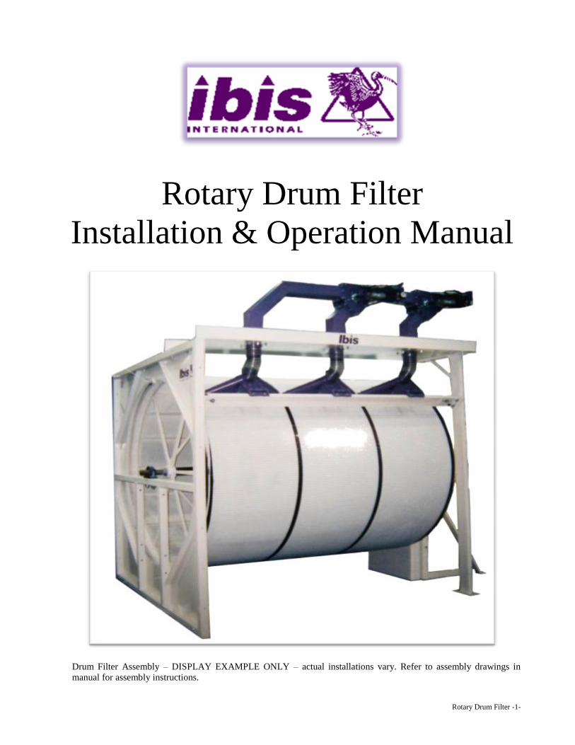
Rotary Drum Filter
Installation & Operation Manual
Drum Filter Assembly – DISPLAY EXAMPLE ONLY – actual installations vary. Refer to assembly drawings in
manual for assembly instructions.
Rotary Drum Filter -2-
Introduction
Thank you for selecting the Ibis Rotary Drum Filter. The information in this manual will be helpful
to install and apply the Ibis Filter System to the manufacturing process.
The Ibis Drum Filter is designed for each application to efficiently use the available space and
power. When properly installed, the Ibis Drum Filter will operate with minimal maintenance.
The Ibis Drum Filter will interface with the other components in the production system and will
provide reliable, automatic operation to remove fine particles from the air stream so that clean air
can be exhausted back into the plant or atmosphere.
These instructions are for all sizes of Ibis Drum Filters, although the size may vary from the Drum
Filters depicted in the drawings. The size of the Drum Filter is determined by the diameter of the
drum and the number of sections. For example, a drum that is 7 feet in diameter and has 3 cages
would be denoted as a 7-3 Drum Filter. All diameters are in feet (1 foot = 305 mm.)
OPERATION
Dirty air is introduced into the Drum Filter Enclosure to the outside of the drum. The air is drawn
through the Filter Media by the Main System Fan and the particles become suspended in the media.
The particles are then vacuumed off the media by Vacuum Nozzles installed in the drum chamber.
The particles are then returned to the process or collected in an ‘off-line’ collector.
NOTE: If your Drum Filter is equipped with multiple stages of filtration, refer to the
provided manual for each stage of additional filtration.
The air pressure drop across the Filter Media is monitored constantly by electrical components. If
the pressure drop goes beyond the operating set point a warning light and alert is given. (HIGH &
LOW on the top of the control panel)
All electrical components of the Drum Filter are enclosed in the Control Panel. The electrical and
mechanical sensors for the electrical system are located as necessary on the Drum Filter or
Enclosure. Control of the Drum Filter motor is done through this panel. Auxiliary control is
interfaced with other plant systems.
The operation of the Drum Filter should be checked on a daily basis by trained personnel. The
mechanical and electrical condition of the entire system should be checked with particular attention
being paid to the filter media, seals, nozzles and rotation.
Rotary Drum Filter -3-
INSTALLATION - DRUM FILTER/PLENUM WALL
AND 45o NOZZLE SYSTEM
1. Inventory the entire shipment by using the provided crate list and inspect for missing parts or
damage. Report any damaged or missing parts immediately.
2. Clean installation and assembly area thoroughly. Confirm that there is sufficient space around
the unit for easy access for maintenance / service and the layout allows space for obstructions
such as beams, plumbing, electrical conduits, emergency exit, walkways, doors, etc.
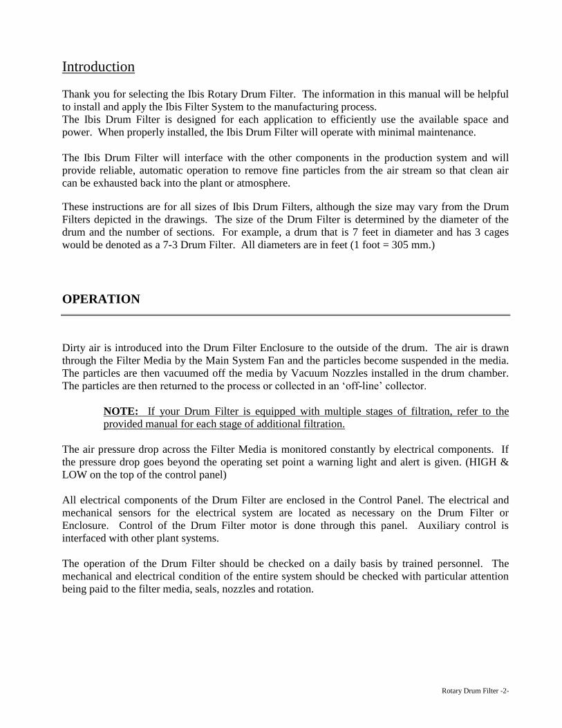
3. Use a marker or a piece of chalk to mark the location of the corners of the enclosure (make a
box), the plenum wall, rear bearing stand and the main system fan. Make sure that the layout
on the floor is square to within a 1/2" or 12mm and that the layout contains all the equipment
that you are installing in that area.
4. Instructions for setting Drum Filter in place (Reference Ibis installation drawings in the job
manual) please refer to the bill of material descriptions, not the item numbers on the
installation drawing.
4.1. Determine the location of the Plenum Wall from the Enclosure Panel layout drawing and
mark an outline to represent where the Plenum Wall will be placed.
4.2. Locate and mark the centerline of the Drum Filter Shaft, squaring (90o) it to the Plenum
Wall.
4.3. Place the Plenum Wall in position and mark the location of the holes for the anchors in
the floor by marking through the holes in the Plenum Wall Base.
4.4. Drill and install the floor anchors. Remove the Plenum Wall if necessary
4.5. Place Plenum Wall and fasten securely to the floor. Verify that the Plenum Wall is level
and plumb. Install shims / washers if necessary. The drum will not turn or operate
properly if the Plenum Wall is not level and plumb.
4.6. Support the Plenum Wall with the Plenum Wall Braces. Use the two Plenum Wall
Connecting Braces if the Plenum Wall is split. The braces bolt to the Plenum Wall and
are anchored to the floor.
Rotary Drum Filter -4-
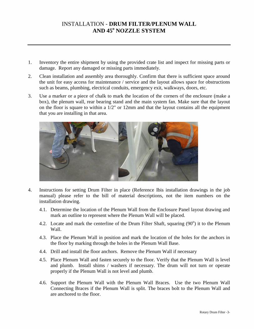
4.7. If the plenum wall is split you will have to fill the gap in the angle rings between the top
and bottom plenum wall panels with body filler (supplied by Ibis). Allow filler to dry
and then sand smooth. This will allow the primary seal to slide smoothly around the angle
ring
5.
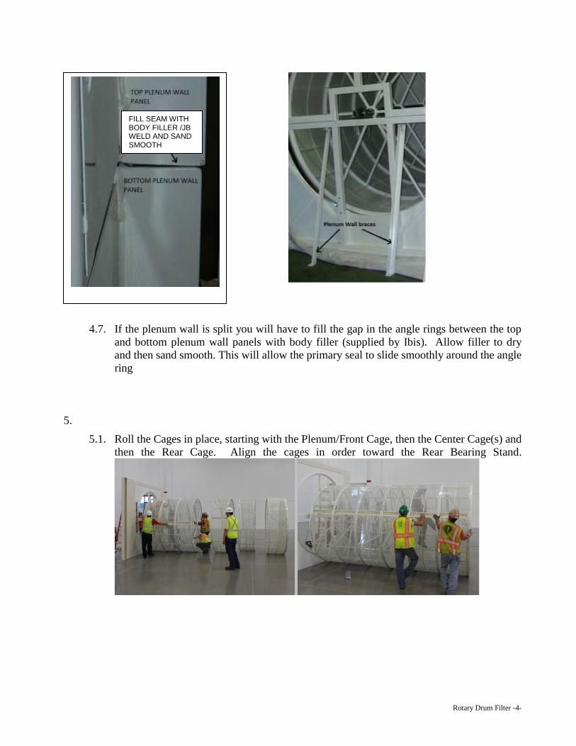
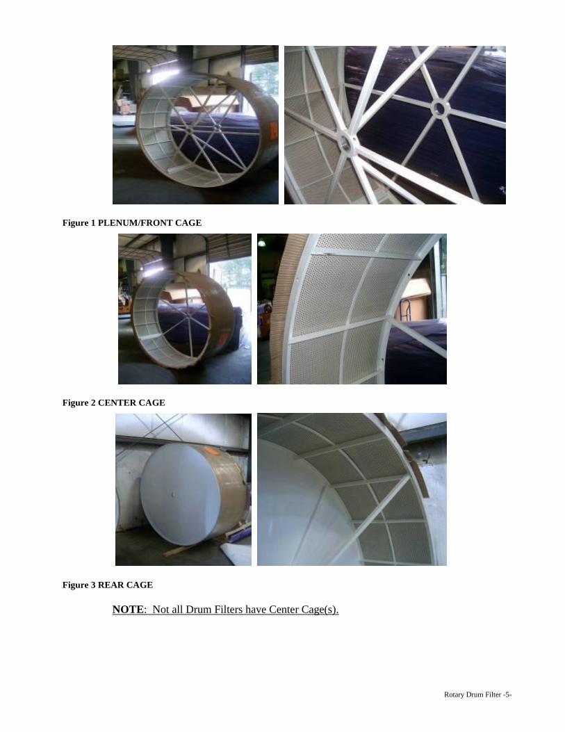
5.1. Roll the Cages in place, starting with the Plenum/Front Cage, then the Center Cage(s) and
then the Rear Cage. Align the cages in order toward the Rear Bearing Stand.
FILL SEAM WITH BODY FILLER /JB WELD AND SAND SMOOTH
Rotary Drum Filter -5-
Figure 1 PLENUM/FRONT CAGE
Figure 2 CENTER CAGE
Figure 3 REAR CAGE
NOTE: Not all Drum Filters have Center Cage(s).
Rotary Drum Filter -6-
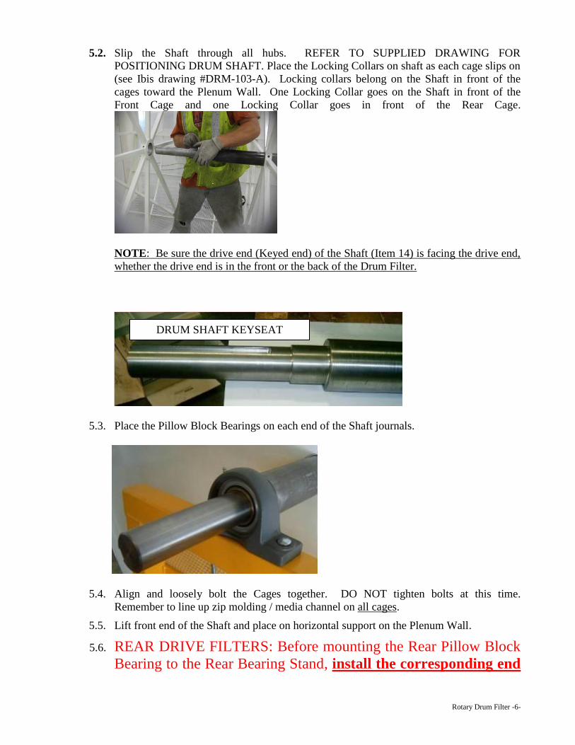
5.2. Slip the Shaft through all hubs. REFER TO SUPPLIED DRAWING FOR
POSITIONING DRUM SHAFT. Place the Locking Collars on shaft as each cage slips on
(see Ibis drawing #DRM-103-A). Locking collars belong on the Shaft in front of the
cages toward the Plenum Wall. One Locking Collar goes on the Shaft in front of the
Front Cage and one Locking Collar goes in front of the Rear Cage.
NOTE: Be sure the drive end (Keyed end) of the Shaft (Item 14) is facing the drive end,
whether the drive end is in the front or the back of the Drum Filter.
5.3. Place the Pillow Block Bearings on each end of the Shaft journals.
5.4. Align and loosely bolt the Cages together. DO NOT tighten bolts at this time.
Remember to line up zip molding / media channel on all cages.
5.5. Lift front end of the Shaft and place on horizontal support on the Plenum Wall.
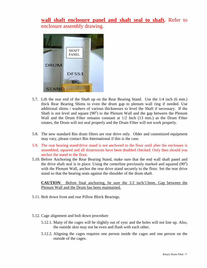
5.6. REAR DRIVE FILTERS: Before mounting the Rear Pillow Block
Bearing to the Rear Bearing Stand, install the corresponding end
DRUM SHAFT KEYSEAT
Rotary Drum Filter -7-
wall shaft enclosure panel and shaft seal to shaft. Refer to
enclosure assembly drawing.
5.7. Lift the rear end of the Shaft up on the Rear Bearing Stand. Use the 1/4 inch (6 mm.)
thick Rear Bearing Shims to even the drum gap to plenum wall ring if needed. Use
additional shims / washers of various thicknesses to level the Shaft if necessary. If the
Shaft is not level and square (90o) to the Plenum Wall and the gap between the Plenum
Wall and the Drum Filter remains constant at 1/2 Inch (13 mm.) as the Drum Filter
rotates, the Drum will not seal properly and the Drum Filter will not work properly.
5.8. The new standard Ibis drum filters are rear drive only. Older and customized equipment
may vary, please contact Ibis International if this is the case.
5.9. The rear bearing stand/drive stand is not anchored to the floor until after the enclosure is
assembled, squared and all dimensions have been doubled checked. Only then should you
anchor the stand to the floor.
5.10. Before Anchoring the Rear Bearing Stand, make sure that the end wall shaft panel and
the drive shaft seal is in place. Using the centerline previously marked and squared (90o)
with the Plenum Wall, anchor the rear drive stand securely to the floor. Set the rear drive
stand so that the bearing seats against the shoulder of the drum shaft.
CAUTION: Before final anchoring, be sure the 1/2 inch/13mm. Gap between the
Plenum Wall and the Drum has been maintained.
5.11. Bolt down front and rear Pillow Block Bearings.
5.12. Cage alignment and bolt down procedure
5.12.1. Many of the cages will be slightly out of sync and the holes will not line up. Also,
the outside skin may not be even and flush with each other.
5.12.2. Aligning the cages requires one person inside the cages and one person on the
outside of the cages.
SHAFT
PANEL
Rotary Drum Filter -8-
5.12.3. The person inside the cages will require a hammer, C-Clamp or clamping pliers,
drift pin, wrench and sockets. The person on the outside of the cage will require
only a hammer.
5.12.4. Begin with joint between the Front Cage and the next cage, whether it is a Center
Cage or the Rear Cage. Make sure that the media retaining channels on each of
the cage sections are aligned with each other before they are bolted together.
5.12.5. To align the holes, work the drift tool through the holes until two of the holes
align and a bolt can be slipped through the holes.
5.12.6. To even and flush the outside of the cages, put the C-Clamp on the rails near the
aligned holes and then tap either on the outside or the inside of the cage on the
angle rings. When the outside edge is even and flush, insert and tighten the bolt to
secure.
5.12.7. Repeat the procedures in 5.12.5 and 5.12.6 for the entire joint between the two
cages. A good idea is to skip a bolt hole to allow room to use the drift. After the
drift pin is moved to the next location, the bolt should be placed in the hole that
the drift was removed from and tightened. After the procedure is completed for
the entire joint and all holes are aligned and the surfaces are flush, put bolts in any
remaining holes.
5.12.8. Repeat 5.12.5 through 5.12.7 for each joint in between the cages.
5.12.9. After the procedures are completed, the entire drum should be brought into
alignment and an accurate cylinder is formed.
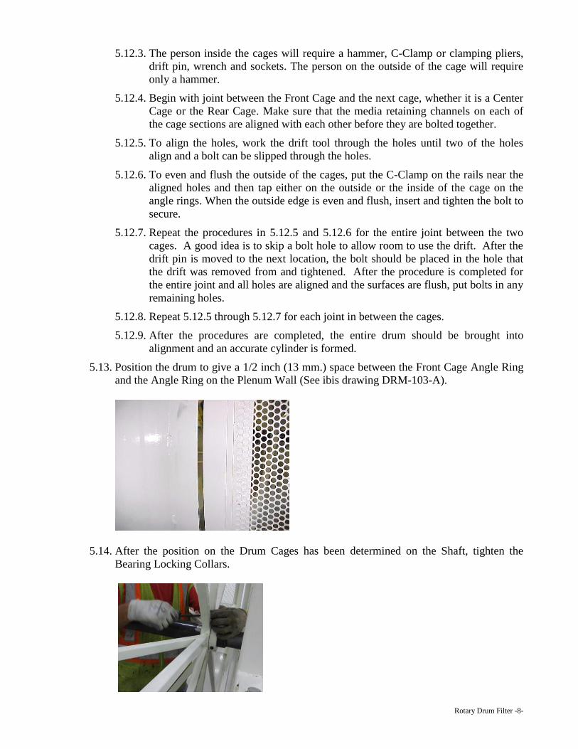
5.13. Position the drum to give a 1/2 inch (13 mm.) space between the Front Cage Angle Ring
and the Angle Ring on the Plenum Wall (See ibis drawing DRM-103-A).
5.14. After the position on the Drum Cages has been determined on the Shaft, tighten the
Bearing Locking Collars.
Rotary Drum Filter -9-
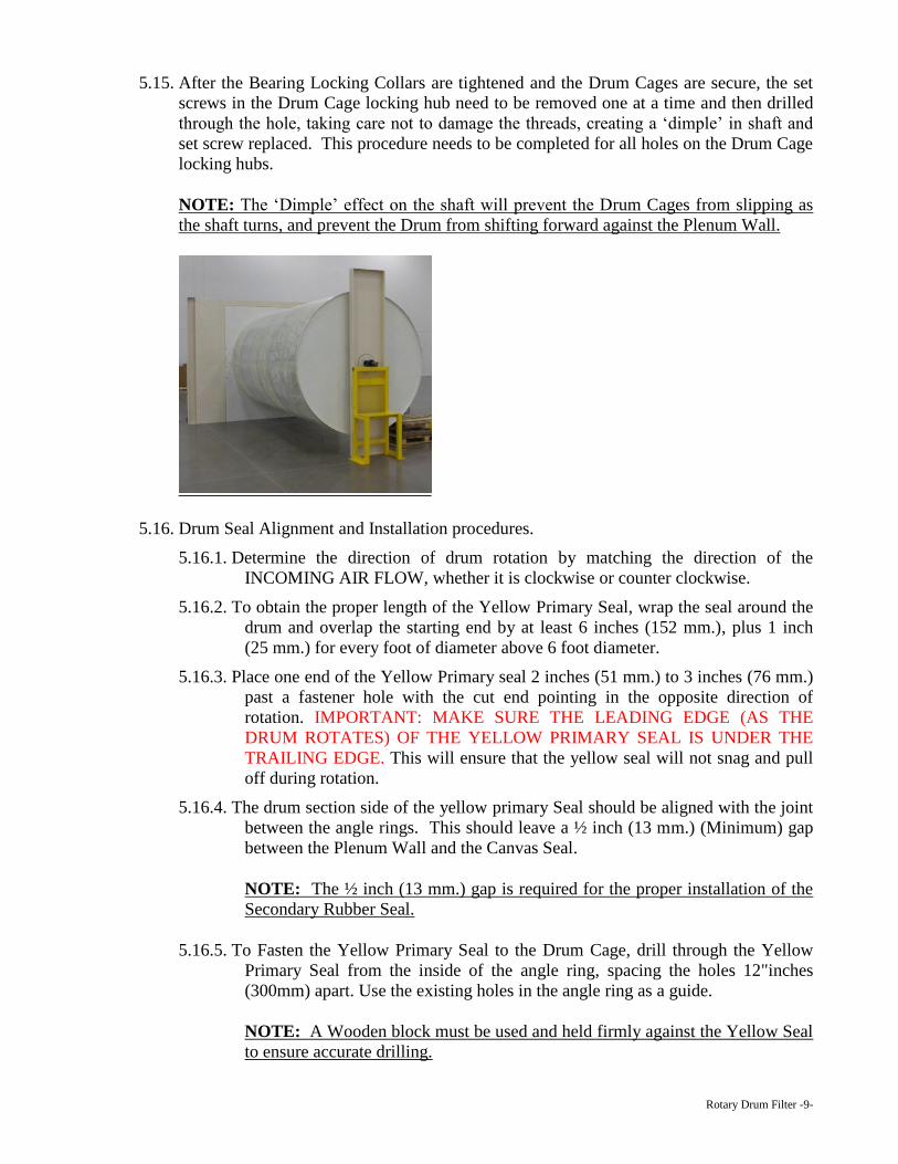
5.15. After the Bearing Locking Collars are tightened and the Drum Cages are secure, the set
screws in the Drum Cage locking hub need to be removed one at a time and then drilled
through the hole, taking care not to damage the threads, creating a ‘dimple’ in shaft and
set screw replaced. This procedure needs to be completed for all holes on the Drum Cage
locking hubs.
NOTE: The ‘Dimple’ effect on the shaft will prevent the Drum Cages from slipping as
the shaft turns, and prevent the Drum from shifting forward against the Plenum Wall.
5.16. Drum Seal Alignment and Installation procedures.
5.16.1. Determine the direction of drum rotation by matching the direction of the
INCOMING AIR FLOW, whether it is clockwise or counter clockwise.
5.16.2. To obtain the proper length of the Yellow Primary Seal, wrap the seal around the
drum and overlap the starting end by at least 6 inches (152 mm.), plus 1 inch
(25 mm.) for every foot of diameter above 6 foot diameter.
5.16.3. Place one end of the Yellow Primary seal 2 inches (51 mm.) to 3 inches (76 mm.)
past a fastener hole with the cut end pointing in the opposite direction of
rotation. IMPORTANT: MAKE SURE THE LEADING EDGE (AS THE
DRUM ROTATES) OF THE YELLOW PRIMARY SEAL IS UNDER THE
TRAILING EDGE. This will ensure that the yellow seal will not snag and pull
off during rotation.
5.16.4. The drum section side of the yellow primary Seal should be aligned with the joint
between the angle rings. This should leave a ½ inch (13 mm.) (Minimum) gap
between the Plenum Wall and the Canvas Seal.
NOTE: The ½ inch (13 mm.) gap is required for the proper installation of the
Secondary Rubber Seal.
5.16.5. To Fasten the Yellow Primary Seal to the Drum Cage, drill through the Yellow
Primary Seal from the inside of the angle ring, spacing the holes 12"inches
(300mm) apart. Use the existing holes in the angle ring as a guide.
NOTE: A Wooden block must be used and held firmly against the Yellow Seal
to ensure accurate drilling.
Rotary Drum Filter -10-
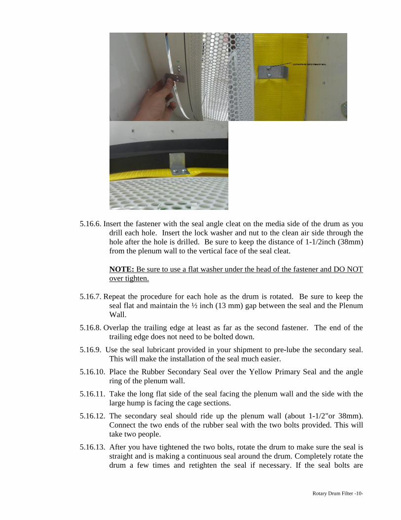
5.16.6. Insert the fastener with the seal angle cleat on the media side of the drum as you
drill each hole. Insert the lock washer and nut to the clean air side through the
hole after the hole is drilled. Be sure to keep the distance of 1-1/2inch (38mm)
from the plenum wall to the vertical face of the seal cleat.
NOTE: Be sure to use a flat washer under the head of the fastener and DO NOT
over tighten.
5.16.7. Repeat the procedure for each hole as the drum is rotated. Be sure to keep the
seal flat and maintain the ½ inch (13 mm) gap between the seal and the Plenum
Wall.
5.16.8. Overlap the trailing edge at least as far as the second fastener. The end of the
trailing edge does not need to be bolted down.
5.16.9. Use the seal lubricant provided in your shipment to pre-lube the secondary seal.
This will make the installation of the seal much easier.
5.16.10. Place the Rubber Secondary Seal over the Yellow Primary Seal and the angle
ring of the plenum wall.
5.16.11. Take the long flat side of the seal facing the plenum wall and the side with the
large hump is facing the cage sections.
5.16.12. The secondary seal should ride up the plenum wall (about 1-1/2"or 38mm).
Connect the two ends of the rubber seal with the two bolts provided. This will
take two people.
5.16.13. After you have tightened the two bolts, rotate the drum to make sure the seal is
straight and is making a continuous seal around the drum. Completely rotate the
drum a few times and retighten the seal if necessary. If the seal bolts are
Rotary Drum Filter -11-
tightened all the way and the seal is still loose, REMOVE seal and relocate the
brackets of one end and try the seal again.
- CAUTION – DO NOT use any form of liquid or spray lubricant. A liquid
lubricate will cause the seal to become sticky and bind rotation.
NOTE: If there are any problems with seal alignment and installation, DO
NOT operate until the factory has been consulted for assistance.
45 degree nozzle and optional 90 degree nozzle installation
5.17. The nozzle support channel can install at the 90 degree or the 45 degree position using
the special angle brackets. The distance from the plenum wall to the end wall inside skin
is crucial.
5.18. Mount the Angle Brackets to the End Wall (field drill holes in wall panel) and the
Plenum Wall, and make sure the nozzle rail is parallel to the drum. Then bolt the Nozzle
Channel between the Angle brackets. Note that the holes are not symmetrical, and the
short side goes to the plenum wall. Be sure and align the Nozzle Channel holes with the
center of the cages.
5.19. Mount the Nozzle Brackets to the Nozzle Channel with slot of Nozzle approximately ¼
inch (6 mm.) to 3/8inch (8mm) off media surface and plumb with each other.
5.20. Slip the big end of 45o OVC Elbow Assembly over outlet of the Nozzle. Make sure it is a
tight fit. Caulk if necessary.
5.21. Install the standard nozzle manifold or optional pneumatic manifold at any time after the
roof panels have been installed. Place the manifold in line with the nozzle rail (make sure
that the flange of the manifold will NOT strike the standing seams of the roof panels.
Mark the location of the 4inch (100mm) pipe. Cut holes. Place the manifold in the cut
holes, and then match drill hole locations. Mount the manifold with the round head bolts.
Round head to the inside.
5.22. If using a standard media with no zipper, lay the media out in front of the drum inside of
the enclosure. Attach one side to the zip strip with the pile (fluffy hairy) facing outward.
Insert one end in the Zip Molding by pushing on the media and using a slight rolling
motion. Make sure that you have lined it up to cover the entire drum front to back.
Having excess lying over the secondary seal is ok. Try not to have too much excess on
the drive side as this can cause accumulation of material.
5.23. Rotate the drum so that the media slowly unrolls and covers the drum. Once rotated and
the two ends meet, slightly pull the media tighter as you press into the zip strip using the
provided zip tool. Do this all the way from one end to the other working out any
wrinkles.
5.24. Insert the trailing end of the Filter Media into the other Zip Molding and CAREFULLY
trim excess Filter Media.
NOTE: MEDIA SHOULD BE WRINKLE FREE!
Rotary Drum Filter -12-
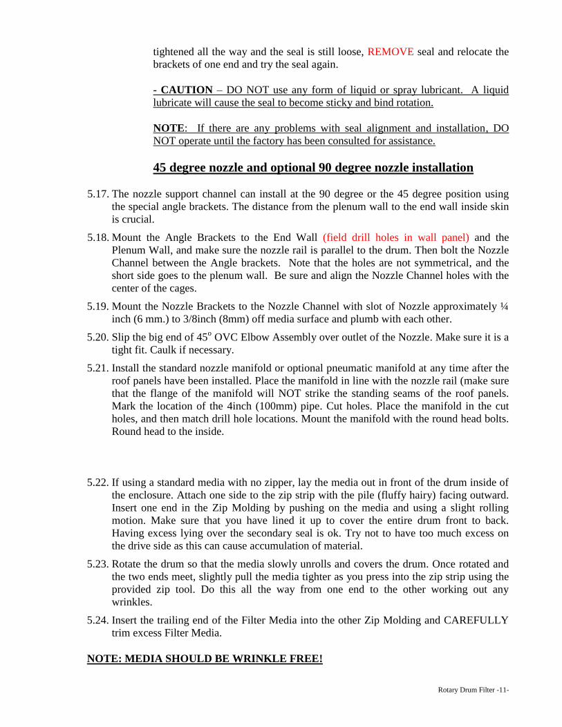
5.25. Install the Cover Plate to the Drum Cages using M6-1x50mm bolts (provided). It is
acceptable to let some excess media cover part of the V-ring seal. Check for HOLES or
gaps, if you can see white metal or inside the cages STOP and FIX before you go any
further
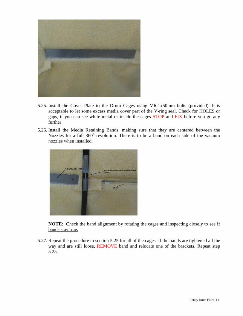
5.26. Install the Media Retaining Bands, making sure that they are centered between the
Nozzles for a full 360o revolution. There is to be a band on each side of the vacuum
nozzles when installed.
NOTE: Check the band alignment by rotating the cages and inspecting closely to see if
bands stay true.
5.27. Repeat the procedure in section 5.25 for all of the cages. If the bands are tightened all the
way and are still loose, REMOVE band and relocate one of the brackets. Repeat step
5.25.
Rotary Drum Filter -13-
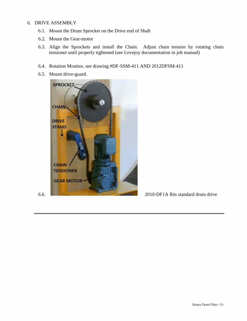
6. DRIVE ASSEMBLY
6.1. Mount the Drum Sprocket on the Drive end of Shaft
6.2. Mount the Gear-motor
6.3. Align the Sprockets and install the Chain. Adjust chain tension by rotating chain
tensioner until properly tightened (see Lovejoy documentation in job manual)
6.4. Rotation Monitor, see drawing #DF-SSM-411 AND 2012DFSM-411
6.5. Mount drive-guard.
6.6. 2010-DF1A Ibis standard drum drive
Rotary Drum Filter -14-
Torque-Tamer tm Installation Instructions Ibis International, Inc uses an adjustable slip clutch on drum filter drives. In most instances, this device is used to
transmit the rotational force provided by a gear motor to a driven shaft. In the case of the drum filter, it is used to provide
adjustable resistance to protect the reducer and components. Over the years, the service department has seen some
confusion among our customers on the proper procedure for adjusting these clutches. With the help of a diagram of a
Dodge TORQUE-TAMER™, the brand most commonly used on Ibis drum filters, let’s go through the proper adjustment
procedure for this important device.
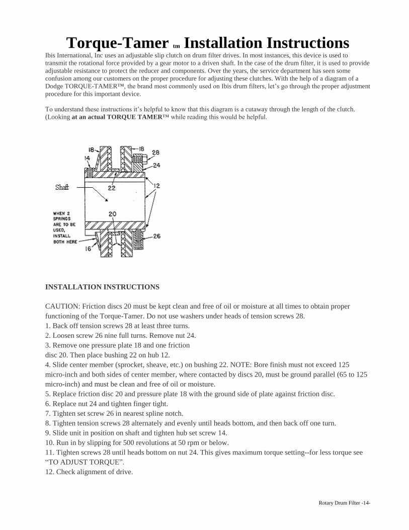
To understand these instructions it’s helpful to know that this diagram is a cutaway through the length of the clutch.
(Looking at an actual TORQUE TAMER™ while reading this would be helpful.
INSTALLATION INSTRUCTIONS
CAUTION: Friction discs 20 must be kept clean and free of oil or moisture at all times to obtain proper
functioning of the Torque-Tamer. Do not use washers under heads of tension screws 28.
1. Back off tension screws 28 at least three turns.
2. Loosen screw 26 nine full turns. Remove nut 24.
3. Remove one pressure plate 18 and one friction
disc 20. Then place bushing 22 on hub 12.
4. Slide center member (sprocket, sheave, etc.) on bushing 22. NOTE: Bore finish must not exceed 125
micro-inch and both sides of center member, where contacted by discs 20, must be ground parallel (65 to 125
micro-inch) and must be clean and free of oil or moisture.
5. Replace friction disc 20 and pressure plate 18 with the ground side of plate against friction disc.
6. Replace nut 24 and tighten finger tight.
7. Tighten set screw 26 in nearest spline notch.
8. Tighten tension screws 28 alternately and evenly until heads bottom, and then back off one turn.
9. Slide unit in position on shaft and tighten hub set screw 14.
10. Run in by slipping for 500 revolutions at 50 rpm or below.
11. Tighten screws 28 until heads bottom on nut 24. This gives maximum torque setting--for less torque see
“TO ADJUST TORQUE”.
12. Check alignment of drive.
Rotary Drum Filter -15-
TO ADJUST TORQUE of the Torque Tamer:
1. Back off tension screws 28 at least three turns.
2. Loosen adjusting nut set screw 26 at least nine turns.
3. Reset adjusting nut 24 (Turn clockwise for more torque or counterclockwise for less. Do not tighten
adjusting nut beyond finger tight.)
4. Tighten adjusting nut set screw 26 in nearest spline notch. (Do not tighten setscrew on threads of hub.)
5. Tighten tension screws 28 alternately and evenly until heads bottom. Do not use washers under heads
of these screws.
6. Check alignment of drive. If necessary, loosen hub set screw 14 and shift hub 12 on shaft.
A shaft would extend from left to right through the bore of the hub #12 (through the area
marked shaft on the diagram). In most cases, a sprocket would be captured between the two friction discs
#20 and this sprocket is free to rotate on the bushing #22. The hub # 12 is keyed to the shaft; therefore
any rotational force applied to the sprocket will be transmitted to the shaft through the friction discs #20
to the pressure plates # 18 which are splined to the hub #12. The amount of torque transmitted to the shaft
depends on how much the spring #16 is compressed, which is determined by the distance between the
spring and the adjusting nut #24. It is important to understand that in order to increase or decrease the
amount of torque transmitted, the adjusting nut #24 must be turned clockwise to increase, or counter
clockwise to decrease the torque. See the above instructions for details. Do not try to adjust the clutch by
loosening or tightening the tension screws #28, results will be unpredictable. The only position these
screws should be in when the clutch is in operation is fully bottomed out. Do not over tighten these bolts,
the heads twist off easily.
MAINTENANCE
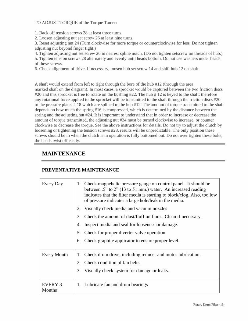
PREVENTATIVE MAINTENANCE
Every Day 1. Check magnehelic pressure gauge on control panel. It should be
between .5” to 2” (13 to 51 mm.) water. An increased reading
indicates that the filter media is starting to block/clog. Also, too low
of pressure indicates a large hole/leak in the media.
2. Visually check media and vacuum nozzles
3. Check the amount of dust/fluff on floor. Clean if necessary.
4. Inspect media and seal for looseness or damage.
5. Check for proper diverter valve operation
6. Check graphite applicator to ensure proper level.
Every Month 1. Check drum drive, including reducer and motor lubrication.
2. Check condition of fan belts.
3. Visually check system for damage or leaks.
EVERY 3
Months
1. Lubricate fan and drum bearings
Rotary Drum Filter -16-
FILTER MEDIA MAINTENANCE
Filter Media on the Drum Filter is most commonly a one-piece high-pile filter blanket that
efficiently collects particles from the air stream. The Filter Media is a knit fabric and will
wear, stretch and tear if proper maintenance and care is not taken. Lack of care can reduce
the efficiency of the Drum Filter and could allow particles to past through the Filter Media.
Proper operation of the Vacuum Nozzles is critical to proper care and maintenance of the
Filter Media. The Vacuum Nozzles remove particles from the Filter Media and prevent
particles from building up and clogging the filter. If the nozzles are too far from the media,
the vacuum will not remove the particles. If the nozzles are too close to the media, they may
rub on the media and wear or tear the media. See the Vacuum Nozzle section for more
detailed information on setting the Vacuum Nozzles.
The best way to check the condition of the Filter Media is to visually inspect the media and
to check the differential pressure across the media. A gauge should be installed in the panel
to show the differential pressure across the media. The differential pressure should be
checked daily. The engineering staff will determine the proper differential pressure. If the
pressure is out of the normal limits, the causes of the increase or decrease should be
determine and corrected before further operation of the drum. High pressure can be caused
by a blocked or clogged Filter Media. Check the nozzles to ensure proper location and
sufficient vacuum. Low pressure can be caused by torn media.
To replace worn or damaged media, remove the old media and refer to the Assembly and
Installation Instructions for Drum Filters sections 5.21 through 5.26 on how to properly
install the Filter Media.
VACUUM NOZZLE MANIFOLD OPERATION
The Vacuum Nozzle Manifold on your Drum Filter is used in conjunction with the Vacuum
Nozzles to remove the particles from the Filter Media. The Vacuum Nozzle manifold on a
Drum Filter uses a series of Diverter Valves to direct the vacuum to the appropriate nozzles
in a controlled sequence.
The Vacuum Nozzle Manifold assembly, the flexible duct to the Vacuum Nozzles and the
duct to the Vacuum Fan must be maintained properly to provide adequate vacuum to clean
the Filter Media. If the Filter Media is not cleaned properly, the Drum Filter system will
cease to operate correctly and could cause hazardous conditions.
The Vacuum Nozzle Manifold Diverter Valve operation sequence is specifically designed for
each type of Drum Filter. Changing the sequence may alter the effectiveness of the Drum
Filter system. The Control Panel regulates the sequence of the valves and the sequence
should not be changed without consulting with ibis technicians first.
The Vacuum Nozzle Manifold Diverter Valves are opened and closed by air operated
solenoids and actuators. The air supply to the Diverter Valves should be clean, dry and reach
the Diverter Valves at 60 PSI and 1 CFM in order to operate correctly. If water reaches the
Rotary Drum Filter -17-
solenoids or actuators, they will corrode and cease to operate correctly. The air exhaust
should be adjusted on the Diverter Valves to cushion the valve when it opens and closes.
At the start of the each shift, the operator should observe the entire sequence of opening and
closing for the Diverter Valves. If there is any operational failure or damage, it should be
corrected immediately before further damage can occur.
SETTING AND MAINTAINING NOZZLES
The Vacuum Nozzles on the Drum Filter must be set and maintained properly for satisfactory
removing of particles from the Filter Media. The Vacuum Nozzles should be adjusted so
they clear the Filter Media by approximately 3/8 inch / 8-10 mm, or just enough room to slip
a finger tip into the gap. If the nozzle is too far away from the Filter Media, the vacuum will
be insufficient to clean the media, and if the nozzle is allowed to ride on the Filter Media, the
media will be worn or damaged. The Nozzle Bracket should be cleaned and checked for
wear periodically to allow the nozzle to move freely in the bracket.
Proper nozzle opening size must be used for each particular operation. Contact ibis for
assistance in selecting the proper size nozzle to meet your requirements.
LUBRICATION SCHEDULES
The ibis Drum Filter should be lubricated as a part of the overall maintenance or lubricating
schedules or the entire manufacturing plant. The lubrication schedules of the Drum Filter
will include checking and maintaining the level of the oil in the gear boxes and lubrication of
the drum and fan shaft bearings.
The Bearings on the Drum Shaft and Blower Shafts should be greased with High Grade
grease every three months. The bearings do not require a large amount of grease (two or
three shots from a grease gun will be sufficient). Do not pump enough grease in the bearings
to force grease out of the seals. Be sure to wipe any excess grease from around the bearings.
Too much grease in the bearing will cause heat to build up and break down the grease, and
forcing grease out around the seals will cause the seal to fail. Any excess grease that is left
on the bearings will collect dust and fibers and will become abrasive and wear out the
bearings.
The bearing in the Drum Filter Drive Motors may need grease depending upon the type and
application. If the bearings are able to be greased, do it every three months. To grease a
greaseable motor bearing, the top and bottom fill plugs need to be removed and a grease
fitting installed in the top hole. Grease should be pumped into the bearing to flush out the
old grease until only new grease is being pumped through the bearing. Allow the motor to
run for five minutes and then wipe away the excess grease. Reinstall the filler plugs in the
motor bearing access holes.
The Gear Box Reducer oil level should be checked every month. The oil level is checked by
removing the check plug on the side of gearbox. The oil in the gearbox should be at the level
of the hole. If the oil is below the hole, the gearbox should be filled with the proper oil until
oil runs out the check hole. Once a year the Gear Box cover should be removed and the
gears and seals checked for wear. If excessive wear is detected, the gear should be replaced.
Rotary Drum Filter -18-
It may be necessary to place all gears at the same time to ensure that excess wear will not
occur to the new gear. Any time the Gear Box is open, the gears should be checked for wear.
CLEANING
ALL surfaces of the Drum Filter should be vacuumed periodically using an ibis Central
Vacuum System to remove built up dust and fluff particles. DO NOT use compressed air to
clean the Drum Filter. Blowing off the dust will only move it to another area. When
vacuuming, give close attention to the Filter Media and the main Drum Seals to check for
signs of wear or tears.
All bearings should be cleaned periodically of all excess grease and all dust and fluff should
be cleaned from inside and outside the housings.
PARTS LIST
When ordering parts for your Ibis Drum Filter, ALL of the following information must be
included. If ordering by phone, be sure to have this information available when the call is
placed.
1. Part number
2. COMPLETE description of part.
3. Product model number – this is ESSENTIAL
4. Product serial number
5. Quantity needed
6. Length, size, color – where applicable
7. Voltage, RPM, cycle (hertz), ratios, shaft size, etc.
8. Shipping address and method – normal or priority?
9. Customer order number
10. Customer telephone, FAX, E-mail and contact person
Rotary Drum Filter -19-
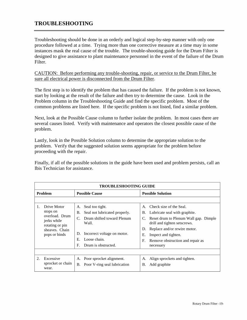
TROUBLESHOOTING
Troubleshooting should be done in an orderly and logical step-by-step manner with only one
procedure followed at a time. Trying more than one corrective measure at a time may in some
instances mask the real cause of the trouble. The trouble-shooting guide for the Drum Filter is
designed to give assistance to plant maintenance personnel in the event of the failure of the Drum
Filter.
CAUTION: Before performing any trouble-shooting, repair, or service to the Drum Filter, be
sure all electrical power is disconnected from the Drum Filter.
The first step is to identify the problem that has caused the failure. If the problem is not known,
start by looking at the result of the failure and then try to determine the cause. Look in the
Problem column in the Troubleshooting Guide and find the specific problem. Most of the
common problems are listed here. If the specific problem is not listed, find a similar problem.
Next, look at the Possible Cause column to further isolate the problem. In most cases there are
several causes listed. Verify with maintenance and operators the closest possible cause of the
problem.
Lastly, look in the Possible Solution column to determine the appropriate solution to the
problem. Verify that the suggested solution seems appropriate for the problem before
proceeding with the repair.
Finally, if all of the possible solutions in the guide have been used and problem persists, call an
Ibis Technician for assistance.
TROUBLESHOOTING GUIDE
Problem Possible Cause Possible Solution
1. Drive Motor
stops on
overload. Drum
jerks while
rotating or pin
sheaves. Chain
pops or binds
A. Seal too tight.
B. Seal not lubricated properly.
C. Drum shifted toward Plenum
Wall.
D. Incorrect voltage on motor.
E. Loose chain.
F. Drum is obstructed.
A. Check size of the Seal.
B. Lubricate seal with graphite.
C. Reset drum to Plenum Wall gap. Dimple
drill and tighten setscrews.
D. Replace and/or rewire motor.
E. Inspect and tighten.
F. Remove obstruction and repair as
necessary
2. Excessive
sprocket or chain
wear.
A. Poor sprocket alignment.
B. Poor V-ring seal lubrication
A. Align sprockets and tighten.
B. Add graphite
Rotary Drum Filter -20-
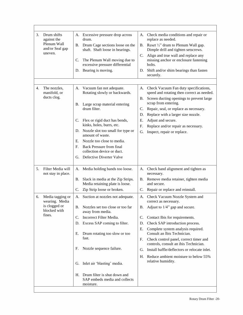
3. Drum shifts
against the
Plenum Wall
and/or Seal gap
uneven.
A. Excessive pressure drop across
drum.
B. Drum Cage sections loose on the
shaft. Shaft loose in bearings.
C. The Plenum Wall moving due to
excessive pressure differential
D. Bearing is moving.
A. Check media conditions and repair or
replace as needed.
B. Reset ½” drum to Plenum Wall gap.
Dimple drill and tighten setscrews.
C. Align and true wall and replace any
missing anchor or enclosure fastening
bolts.
D. Shift and/or shim bearings than fasten
securely.
4. The nozzles,
manifold, or
ducts clog.
A. Vacuum fan not adequate.
Rotating slowly or backwards.
B. Large scrap material entering
drum filter.
C. Flex or rigid duct has bends,
kinks, holes, burrs, etc.
D. Nozzle slot too small for type or
amount of waste.
E. Nozzle too close to media.
F. Back Pressure from final
collection device or duct.
G. Defective Diverter Valve
A. Check Vacuum Fan duty specifications,
speed and rotating then correct as needed.
B. Screen ducting openings to prevent large
scrap from entering.
C. Repair, seal, or replace as necessary.
D. Replace with a larger size nozzle.
E. Adjust and secure.
F. Replace and/or repair as necessary.
G. Inspect, repair or replace.
5. Filter Media will
not stay in place.
A. Media holding bands too loose.
B. Slack in media at the Zip Strips.
Media retaining plate is loose.
C. Zip Strip loose or broken.
A. Check band alignment and tighten as
necessary.
B. Remove media retainer, tighten media
and secure.
C. Repair or replace and reinstall.
6. Media tagging or
wearing. Media
is clogged or
blocked with
fines.
A. Suction at nozzles not adequate.
B. Nozzles set too close or too far
away from media.
C. Incorrect Filter Media.
D. Excess SAP coming to filter.
E. Drum rotating too slow or too
fast.
F. Nozzle sequence failure.
G. Inlet air ‘blasting’ media.
H. Drum filter is shut down and
SAP embeds media and collects
moisture.
A. Check Vacuum Nozzle System and
correct as necessary.
B. Adjust to 1/4” gap and secure.
C. Contact Ibis for requirements.
D. Check SAP introduction process.
E. Complete system analysis required.
Consult an Ibis Technician.
F. Check control panel, correct timer and
controls, consult an ibis Technician.
G. Install baffle/deflectors or relocate inlet.
H. Reduce ambient moisture to below 55%
relative humidity.
Rotary Drum Filter -21-
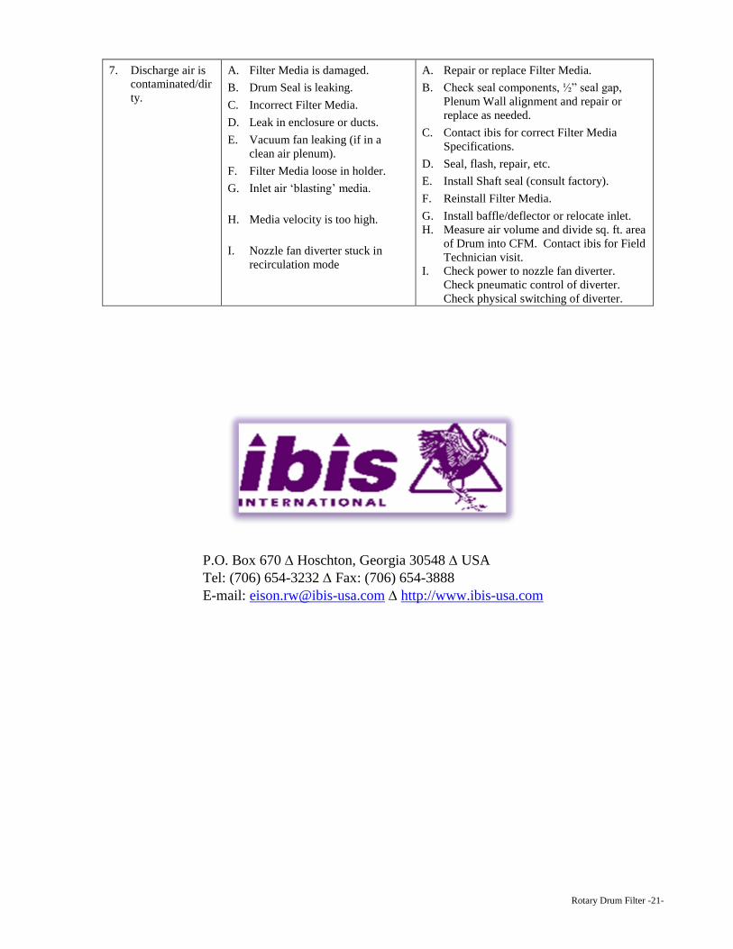
7. Discharge air is
contaminated/dir
ty.
A. Filter Media is damaged.
B. Drum Seal is leaking.
C. Incorrect Filter Media.
D. Leak in enclosure or ducts.
E. Vacuum fan leaking (if in a
clean air plenum).
F. Filter Media loose in holder.
G. Inlet air ‘blasting’ media.
H. Media velocity is too high.
I. Nozzle fan diverter stuck in
recirculation mode
A. Repair or replace Filter Media.
B. Check seal components, ½” seal gap,
Plenum Wall alignment and repair or
replace as needed.
C. Contact ibis for correct Filter Media
Specifications.
D. Seal, flash, repair, etc.
E. Install Shaft seal (consult factory).
F. Reinstall Filter Media.
G. Install baffle/deflector or relocate inlet.
H. Measure air volume and divide sq. ft. area
of Drum into CFM. Contact ibis for Field
Technician visit.
I. Check power to nozzle fan diverter.
Check pneumatic control of diverter.
Check physical switching of diverter.
P.O. P.O. Box 670 Hoschton, Georgia 30548 USA
Tel: (706) 654-3232 Fax: (706) 654-3888
E-mail: [email protected] http://www.ibis-usa.com