Rosenberger - RFMW Ltd. 3-12.pdf · Rosenberger ® RTK ... OUTERSHIELD Silver ... Max. Insertion...
24
Rosenberger ® Microwave High Performance Cables to 70GHz
Transcript of Rosenberger - RFMW Ltd. 3-12.pdf · Rosenberger ® RTK ... OUTERSHIELD Silver ... Max. Insertion...

Rosenberger®
MicrowaveHigh Performance Cables to 70GHz

Table of ContentsIntroduction ............................................................................. Inside CoverTypical Cable Construction ........................................................................ 1Cable Selection Guide ................................................................................ 2Connector Selection Guide .......................................................................4Connector Drawings ..................................................................................5Armor Selection Guide .............................................................................. 7RTK-FLEX RFlex® ........................................................................................8
R1 ........................ 8R2 ........................8
RTK-FLEX Miniature Low Loss CableAssemblies ...................................10M1 ......................10M2 ......................10M3 ......................10
RTK-FLEX Low Loss CableAssemblies .................................................... 12L1 ....................... 12L2 ....................... 12L3 ....................... 12L4 ....................... 12L5 ....................... 12L6 ....................... 12L7 .......................12
RTK-FLEX Low Halogen Cables (StandardTest Cables) ......................... 14H1 .......................14H2 ......................14
RTK-FLEX Ultra Low Loss CableAssemblies ...........................................16U1 .......................16U2 .......................16U3 .......................16U4 .......................16U5 .......................16U6 .......................16W1.......................16
RTK-FLEX Ultralight CableAssemblies ....................................................18T1 .......................18T2 ...................... 18
VNATest Cables ..................................................................................... 20Part Number Designation ........................................................................21CableAssembly Care and Handling .......................................................21Service and Ordering Information ...........................................................21
Rosenberger®
Rosenberger of NorthAmerica, LLCP.O. Box 309 Akron, PA 17501Telephone: +1.717.859.8900 Fax: +1.717.859.7044Email: [email protected]© 2012, Rosenberger NA
RosenbergerHochfrequenztechnik GmbH & Co. KGP.O. Box 1260D-84526TittmoningTelephone: +49-86 84-18-0 Fax: +49-86 84-18-499Email: [email protected] Web:www.rosenberger.com
IntroductionRosenberger® RTK-FLEX is a complete range of high performanceflexible microwave cables built by Rosenberger. The entire RTK-FLEXproduct line is constructed using a low or ultra low density PTFEdielectric offering excellent loss characteristics, outstanding phasestability, and unsurpassed flexibility compared to standard flexiblecables – all without sacrificing mechanical integrity.
Microwave cable for almost any application:• Versatile Low Loss cables offer outstanding performance in
almost any environment
• Ultra Low Loss cables have the lowest insertion loss availableto 18, 26.5, 40, 50, 65 and 70 GHz
• Miniature cables are a superior alternative to traditional RG orsemi-rigid cables
• Ultralight cables provide up to 25% weight savings forspaceflight applications
Key features:• Low SWR (1.25:1 to 40 GHz typical)• Excellent shielding effectiveness
• Precision phase matching
RTK-FLEX high performance cable assemblies are manufactured byRosenberger under the guidance of our Engineering staff. Everycable assembly is tested and supplied with a Return Loss andInsertion Loss plot.
Rosenberger®

1
RTK-FLEX is designed to minimize both reflective and transmission losses while maximizing phase and amplitude stability. This isaccomplished by carefully controlling all materials and processes used to manufacture the cable. Following is a description of the typicalcable construction. Many other designs are available to meet your unique requirements.
Center CONDUCTORSolid or stranded silver-plated copper wire perASTM B-298. In comparison to equal size center conductors, the solid center conductor hasless RF resistance, lower attenuation, and is more amplitude stable with flexure. The stranded center conductor is more flexible and morephase stable with flexure.
DIELECTRICLow density PTFE per MIL-C-17,with a dielectric constant ranging from 1.4 to 1.7 depending on the cable type. Most transmission lossesare caused either directly or indirectly by the dielectric. In addition, the dielectric determines the velocity of propagation, temperature range,power rating, phase and amplitude stability, and contributes to cable flexibility. The RTK-FLEX PTFE dielectric is ideal for these criticalparameters due to its low density and low thermal coefficient of expansion.
INNER SHIELDSilver-plated copper tape perASTM B-298, helically wrapped with 40% minimum overlap between layers. This shield allows for outstandingflexibility while providing 100% coverage. By closely monitoring the precision wrapping process and carefully matching the elasticity of thedielectric to the properties of the silver-plated copper tape, uniform impedance and ideal contact between individual layers of the shield aremaintained.
OUTER SHIELDSilver-plated copper wire perASTM B-298, tightly braided over the inner shield. The braids are primarily for strength but also add additionalRF shielding. For applications where weight is critical such as spaceflight, Rosenberger offers DuPontAracon® as the braiding material.
JACKETFluorinated Ethylene Propylene (FEP), colored light aqua blue. The FEP is excellent because of its high temperature resistance and chemicalinertness. Other materials are available such as Polyurethane (PUR) for Low Halogen and flexible applications andTefzel® for spaceflightand low static applications.
Tefzel® is a DuPont registered trademark.
Rosenberger of North America, LLC P.O. Box 309 Akron, PA 17501 Telephone: 1.717.859.8900 Fax: 1.717.859.7044 Email: [email protected]
Typical Cable Construction

Cable Selection Guide
2 Rosenberger of North America, LLC P.O. Box 309 Akron, PA 17501 Telephone: 1.717.859.8900 Fax: 1.717.859.7044 Email: [email protected]
R-Flex Miniature Low Loss Low Loss
Part Number R1 R2 M1 M2 M3 L1 L2 L3 L4 L5 L6 L7
Impedance Ohms 50
Max. Frequency GHz 5.62040581
Outer Diameter mm 2.54 4.12 1.78 2.34 2.34 3.18 3.73 3.73 5.33 5.33 7.9 7.9
Center Conductor
solid x x x x x x x x
stranded xxxx
Max. Insertion LossdB/m
1 GHz 0.70 0.40 1.12 0.69 0.76 0.49 0.39 0.53 0.26 0.36 0.26 0.36
10 GHz 2.60 1.75 3.54 2.20 2.49 1.61 1.31 1.71 0.92 1.18 0.92 1.18
18 GHz 3.40 2.20 4.82 3.02 3.38 2.23 1.81 2.36 1.28 1.64 1.28 1.64
26.5 GHz - - - - - 2.76 2.23 2.92 1.61 2.03 1.61 2.03
40 GHz - - - - - 3.48 2.85 - - - - -
50 GHz - - - - - 3.97 - - - - - -
Power HandlingWatts (CW)at 10 GHz
58 120 30 59 55 105 150 129 286 248 286 248
Nominal Weigh grams/meter 19.4 43.3 9.8 16.4 16.4 26.2 36.1 36.1 65.6 65.6 65.6 65.6
Static Bend Radius mm 6.4 12.7 2.6 3.2 3.2 5.1 6.4 6.4 10 10 10 10
Detailed Information page 31-2111-019-8
* Includes integral armor (see page 12)
In order to simplify the cable selection process, individual cables have been grouped into product families. Most flexible cable users wantminimal insertion loss consistent with smallest size and weight without sacrificing flexibility. Other parameters will influence price andperformance. Use the table and information below to select the cable that best suits your needs.
• Cables with stranded center conductors tend to be more phase stable with flexure.• Cables with solid center conductors tend to be more amplitude stable with flexure.• In comparison to other product families, the Low Loss cables are the most durable and robust.• For applications up to 26.5 GHz, start with the Low Loss L4 cable.• If the cable will be used in a test lab environment, consider the Low Loss L5 due to its longer flex life and better phase stability withflexure.
• If lower insertion loss is required up to 26.5 GHz, Ultra Low Loss U4 or U3 should be chosen. If the application is less than 18 GHz,choose the Ultra Low Loss U6 or U5 RFlex® .

Cable Selection Guide
thgilartlUssoLwoLartlUnegolaHwoL
Part Number H1 H2 U1 U2 U3 U4 U5 U6 W1 T1 T2
Impedance Ohms 50
Max. Frequency GHz 26.5 26.5 18 40 26.5 26.5 18 18 70 18 26.5
Outer Diameter mm 5.59 5.59 3.61 3.61 5.00 5.21 7.44 7.90 2.35 2.24 5.21
Center Conductor
solid xxx xxxx
stranded x x x x
Max. Insertion LossdB/m
1 GHz 0.26 0.36 0.39 0.36 0.30 0.26 0.20 0.16 0.66 0.69 0.26
10 GHz 0.92 1.18 1.25 1.08 0.92 0.92 0.62 0.49 2.13 2.20 0.92
18 GHz 1.28 1.64 1.67 1.48 1.25 1.05 0.85 0.66 2.92 2.95 1.05
26.5 GHz 1.61 2.03 - 1.81 1.54 1.28 - - 3.51 - 1.28
40 GHz - - - 2.23 - - - - 4.33 - -
50 GHz
65 GHz - - - - - - - - 5.75 - -
70 GHz - - - - - - - - 6.44 - -
- - - - - - - - 5.23 - -
Power HandlingWatts (CW)at 10 GHz
286 248 161 172 281 328 540 643 58 60 328
Nominal Weight grams/meter 65.6 65.6 29.5 32.8 59.1 65.6 121.4 137.8 16.14 10.8 49.2
Static Bend Radius mm 10 10 10 10 13 13 20 32 6.40 6.4 13
Detailed Information page 91-8171-6151-41
• For applications greater than 26.5 GHz but less than 40 GHz, start with the Low Loss L2 cable. If lower loss is required, choose theUltra Low Loss U2 cable.
• For applications up to 50 GHz, use the Low Loss L1 cable.• If size and flexibility are critical, consider the Low Loss L3 or Ultra Low Loss U1 cables.• If the application is for a fixed installation, consider the Miniature cables due to their cost/size/performance ratio.• The Low Halogen polyurethane jacketed cables are also good choices for applications requiring high abrasion resistance.
We recommend these cables as Standard Test Cables.• UseW1 for 70 GHz for optimum phase stability.
If you need assistance, please contact one of our application engineers.
3Rosenberger of North America, LLC P.O. Box 309 Akron, PA 17501 Telephone: 1.717.859.8900 Fax: 1.717.859.7044 Email: [email protected]
Connector Selection Guide
4 Rosenberger of North America, LLC P.O. Box 309 Akron, PA 17501 Telephone: 1.717.859.8900 Fax: 1.717.859.7044 Email: [email protected]
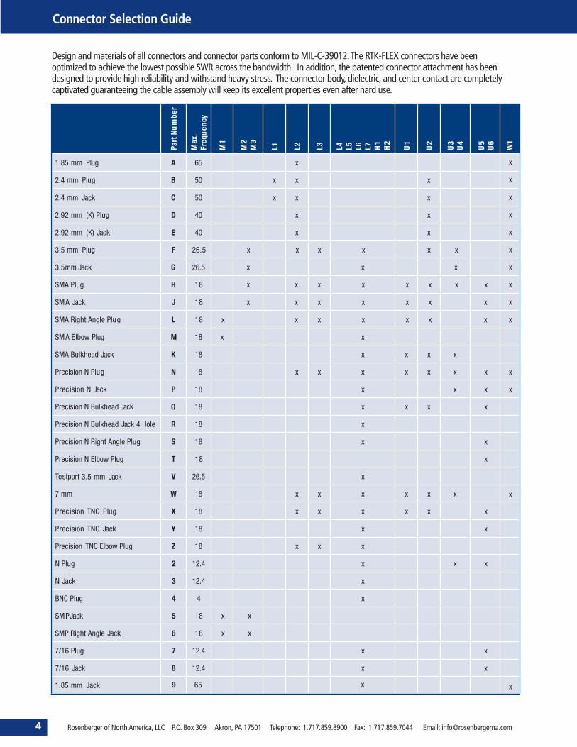
Design and materials of all connectors and connector parts conform to MIL-C-39012.The RTK-FLEX connectors have beenoptimized to achieve the lowest possible SWR across the bandwidth. In addition, the patented connector attachment has beendesigned to provide high reliability and withstand heavy stress. The connector body, dielectric, and center contact are completelycaptivated guaranteeing the cable assembly will keep its excellent properties even after hard use.
Part
Num
ber
Max
.Fr
equ
ency
M1
M2
M3
L1 L2 L3 L4 L5 L6 L7 H1
H2
U1
U2
U3
U4
U5
U W16
1.85 mm Plug
1.85 mm Jack
A x56
2.4 mm Plug B x
x
x
x
x
x
x
x
x
x
x
x
x
x
x
xx05
2.4 mm Jack C xxx05
2.92 mm (K) Plug D xx04
2.92 mm (K) Jack E xx04
3.5 mm Plug F 26.5 x x x x x x
3.5mm Jack G xxx5.62
SMA Plug H 18 x x x x x x x x
SMA Jack J 18 x x x x x x x
SMA Right Angle Plug L 18 x x x x x x x
SMA Elbow Plug M xx81
SMA Bulkhead Jack K xxxx81
Precision N Plug N xxxxxxx81
Precision N Jack P xxx81
Precision N Bulkhead Jack Q xxxx81
Precision N Bulkhead Jack 4 Hole R x81
Precision N Right Angle Plug S xx81
Precision N Elbow Plug T 18 x
Testport 3.5 mm Jack V x5.62
7 mm W xxxxxx81
Precision TNC Plug X xxxxxx81
Precision TNC Jack Y xx81
Precision TNC Elbow Plug Z xxx81
N Plug 2 xxx4.21
N Jack 3 x4.21
BNC Plug 4 x4
SMP Jack 5 18 x x
SMP Right Angle Jack 6 18 x x
7/16 Plug 7 xx4.21
7/16 Jack 8
9
xx4.21
65 x

Rosenberger of North America, LLC P.O. Box 309 Akron, PA 17501 Telephone: 1.717.859.8900 Fax: 1.717.859.7044 Email: [email protected]
QPrecision-N Bulkhead Jack
PPrecision-N Jack
NPrecision-N Plug
MSMA Elbow Plug
LSMA Right Angle Plug
KSMA Bulkhead Jack
JSMA Jack
HSMA Plug
G3.5 mm Jack
F3.5 mm Plug
E2.92 mm (K) Jack
D2.92 mm (K) Plug
A1.85 mm Plug
B2.4 mm Plug
C2.4 mm Jack
TSPrecision-N Right Angle Plug
RPrecision-N Bulkhead Jack
4 Hole
8 11
10.519.3
24.3
8
23.4
9.81
11
8
33.5
8
27,6 27,6 29
8
01ø
35.6
8
01ø
35.6
01ø
34.7
01ø
34.7
46,9
20
ø15
.7
46
22ø
45.8
16.8 2
5.21ø
4.52
37.3
2.44
20
VTestport 3.5mm Jack
ø22
39.2
Coupling Nut Dimensions (where shown) areAcross Flats
Connector Drawings
5

Connector Drawings
6 Rosenberger of North America, LLC P.O. Box 309 Akron, PA 17501 Telephone: 1.717.859.8900 Fax: 1.717.859.7044 Email: [email protected]
XPrecision-TNC Plug
W7 mm
ZPrecision-TNC Elbow Plug
1N Elbow Plug
YPrecision-TNC Jack
5SMP Jack
4BNC Plug
3N Jack
6SMP Right Angle Jack
77/16 Plug
87/16 Jack
2N Plug
19
ø22
41.8
15
7.51øø
10
45.9
7.51øø
10
47
15
48.5
20
55.5 46.9
20
ø15
.7
46
ø15
5.16.6
ø4.
2
3.46.4
ø19
27
67
ø19
68
91.85 mm Jack
29
Armor Selection Guide
Rosenberger of North America, LLC P.O. Box 309 Akron, PA 17501 Telephone: 1.717.859.8900 Fax: 1.717.859.7044 Email: [email protected] 7
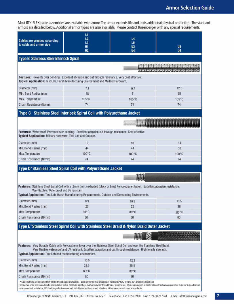
Most RTK-FLEX cable assemblies are available with armor.The armor extends life and adds additional physical protection. The standardarmors are detailed below.Additional armor types are also available. Please contact Rosenberger with any special requirements.

RTK-FLEX RFlex® - FlexibleAlternative To Semi-Rigid
8 Rosenberger of North America, LLC P.O. Box 309 Akron, PA 17501 Telephone: 1.717.859.8900 Fax: 1.717.859.7044 Email: [email protected]
RFlex® assemblies from Rosenberger offers an excellent choice for microwave signal transmission. Employing our high-frequencymicrowave cable technology, Rosenberger has designed RFlex from“the GHz down” rather than “the MHz up”. This precision approachresults in unsurpassed improvements in shielding, stability, durability and lower cost compared to similar products. RFlex is constructedfrom an improved solid PTFE dielectric core underneath a precision wound layer of metalized tape for nearly ideal microwave shielding.Strength and protection are then added via a round wire braid and FEP outer jacket. The result is a cable with true microwaveperformance and excellent mechanical characteristics. RFlex is easy to use because it can be easily stripped and physical sized so that itcan be terminated with standard semi-rigid cable connectors.
Solid Silver-Plated Copper Clad Steel
Solid PTFE Dielectric
Silver-Plated Copper Tape
Silver-Plated Copper Braid
Aqua FEP Jacket
Rosenberger of North America, LLC P.O. Box 309 Akron, PA 17501 Telephone: 1.717.859.8900 Fax: 1.717.859.7044 Email: [email protected] 9
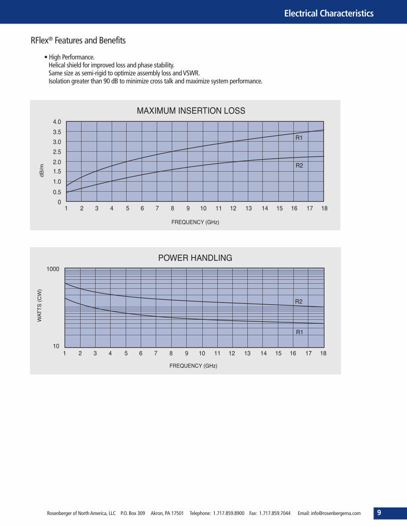
RFlex® Features and Benefits
• High Performance.Helical shield for improved loss and phase stability.Same size as semi-rigid to optimize assembly loss andVSWR.Isolation greater than 90 dB to minimize cross talk and maximize system performance.
Electrical Characteristics

10 Rosenberger of North America, LLC P.O. Box 309 Akron, PA 17501 Telephone: 1.717.859.8900 Fax: 1.717.859.7044 Email: [email protected]
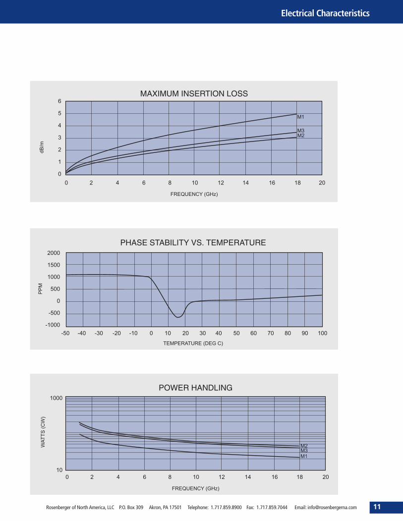
RTK-FLEX Miniature Low Loss CableAssemblies
These general purpose microwave miniature cables have been designed to offer superior electrical performance in the smallest possiblepackage. They are a cost-effective alternative when an RG cable cannot perform to your system needs or when a semi-rigid cable is toocumbersome. The RTK-FLEX Miniature assemblies are available with a large selection of connectors and can be easily customized to meetyour exact requirements.
Solid or Stranded Silver-Plated CopperWire
Low Density PTFE Dielectric
Silver-Plated Copper Shield (Not available for UGN070D)
Silver-Plated Copper Braid
FEP Jacket (Not available for UGN070D)
Rosenberger of North America, LLC P.O. Box 309 Akron, PA 17501 Telephone: 1.717.859.8900 Fax: 1.717.859.7044 Email: [email protected] 11
Electrical Characteristics
12 Rosenberger of North America, LLC P.O. Box 309 Akron, PA 17501 Telephone: 1.717.859.8900 Fax: 1.717.859.7044 Email: [email protected]
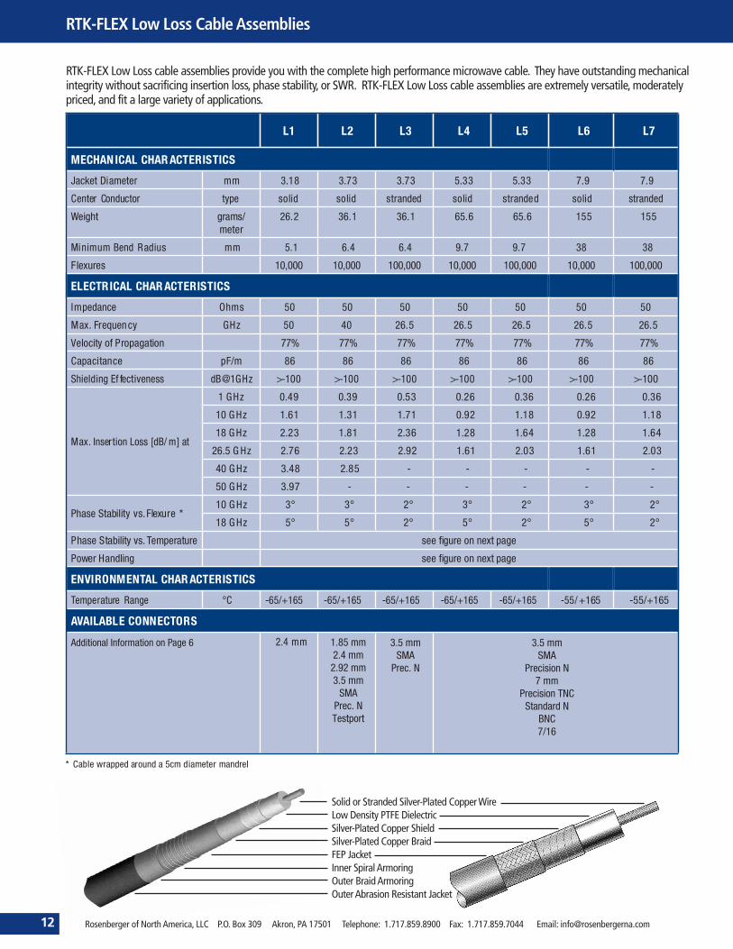
RTK-FLEX Low Loss CableAssemblies
Solid or Stranded Silver-Plated CopperWireLow Density PTFE DielectricSilver-Plated Copper ShieldSilver-Plated Copper BraidFEP JacketInner Spiral ArmoringOuter BraidArmoringOuterAbrasion Resistant Jacket
RTK-FLEX Low Loss cable assemblies provide you with the complete high performance microwave cable. They have outstanding mechanicalintegrity without sacrificing insertion loss, phase stability, or SWR. RTK-FLEX Low Loss cable assemblies are extremely versatile, moderatelypriced, and fit a large variety of applications.

Rosenberger of North America, LLC P.O. Box 309 Akron, PA 17501 Telephone: 1.717.859.8900 Fax: 1.717.859.7044 Email: [email protected] 13
Electrical Characteristics

14 Rosenberger of North America, LLC P.O. Box 309 Akron, PA 17501 Telephone: 1.717.859.8900 Fax: 1.717.859.7044 Email: [email protected]
RTK-FLEX Low HalogenAssemblies
RTK-FLEX Low HalogenAssemblies are the ideal choice for a standard test cable. The polyurethane (PUR) jacket is very flexible irrespectiveof temperature and well able to handle the extremes of temperature experienced in a laboratory. The cables have the same electricalperformance as “Low Loss cable assemblies”with good insertion loss, phase stability and SWR.
Solid or Stranded Silver-Plated CopperWire
Low Density PTFE Dielectric
Silver-Plated Copper Shield
Silver-Plated Copper Braid
Polyurethane Jacket

Rosenberger of North America, LLC P.O. Box 309 Akron, PA 17501 Telephone: 1.717.859.8900 Fax: 1.717.859.7044 Email: [email protected] 15
Electrical Characteristics

* Cable wrapped around a 5cm diameter mandrel** Cable wrapped around a 7.5cm diameter mandrel
U1 U2 U3 U4 U5 U6 W1
MECHANICAL CHARACTERISTICS
09 2.35
solid
16.14
6.4
5,000
50
70
77%
80.4
>-100
0.63
2.25
3.25
4.10
4.80
5.47
6.25
6.65
2°
2°
.744.712.500.516.316.3mmretemaiDtekcaJ
dilosdednartsdilosdednartsdilosdednartsepytrotcudnoCretneC
8.7314.1216.561.958.235.92retem/smargthgieW
Minimum Bend Radius mm 9.7 9.7 12.7 12.7 19 32
000,5000,53000,5000,53000,5000,53seruxelF
ELECTRICAL CHARACTERISTICS
050505050505smhOecnadepmI
81815.625.620481zHGycneuqerF.xaM
%38%38%38%38%38%38noitagaporPfoyticoleV
4.084.084.084.084.084.08m/FpecnaticapaC
Shielding Effectiveness dB@1GHz >-100 >-100 >-100 >-100 >-100 >-100
Max. Insertion Loss [dB/m] at 1 GHz 0.39 0.36 0.30 0.26 0.20 0.16
10 GHz 1.25 1.08 0.92 0.76 0.62 0.49
18 GHz 1.67 1.48 1.25 1.05 0.85 0.66
26.5 GHz - 1.81 1.54 1.28 - -
40 GHz - 2.23
50 GHz - - - - - -
65 GHz - - - - - -
70 GHz - - - - - -
- - - -
Phase Stability vs. Flexure *10 GHz 1° 2° 1° 1° 2°** 3°**
18 GHz 1° 3° 1° 2° 10°** 15°**
egaptxennoerugfieeserutarepmeT.svytilibatSesahP
egaptxennoerugfieesgnildnaHrewoP
ENVIRONMENTAL CHARACTERISTICS
/56-561+/56-561+/56-561+/56-561+/56-561+/56-C°egnaRerutarepmeT +165 56- +165
AVAILABLE CONNECTORS
AMS4egaPnonoitamrofnIlanoitiddAPrecision N
7 mmPrec. TNC
2.4 mm2.92 mm3.5 mm
SMAPrecision N
7 mmPrec. TNC
1.85 mm
7 mmPrec. TNC
3.5 mmSMA
Precision N7 mm
Standard N
SMAPrecision N
Precision TNCStandard N
7/16
2.4 mm
SMAPrecision N
7 mmPrec. TNC
2.92 mm3.5 mm
16 Rosenberger of North America, LLC P.O. Box 309 Akron, PA 17501 Telephone: 1.717.859.8900 Fax: 1.717.859.7044 Email: [email protected]
RTK-FLEX Ultra Low Loss CableAssemblies
RTK-FLEX Ultra Low Loss cable assemblies are optimized to provide the lowest insertion loss available in a flexible cable construction upto 18, 26.5, 40, 50 and 70 GHz. The cables utilize an ultra low density PTFE dielectric that lowers weight and insertion loss, improves elec-trical stability, and provides greater resilience and flexibility when compared to standard microwave cables.
Solid or Stranded Silver-Plated CopperWire
Ultra Low Density PTFE Dielectric
Silver-Plated Copper Shield
Silver-Plated Copper Braid
FEP Jacket

Rosenberger of North America, LLC P.O. Box 309 Akron, PA 17501 Telephone: 1.717.859.8900 Fax: 1.717.859.7044 Email: [email protected] 17
Electrical Characteristics
2000
1500
1000
500
0
-500
-1000
PHASE STABILITY VS. TEMPERATURE
MPP
TEMPERATURE (DEG C)
0-50 -40 -30 -20 -10 10 20 30 40 50 60 70 80 90 100
1000
10
POWER HANDLING
)WC(
STTAW
FREQUENCY (GHz)
U6U5 U4
U3U1
U2
0 5 10 15 20 25 30 35 40

18 Rosenberger of North America, LLC P.O. Box 309 Akron, PA 17501 Telephone: 1.717.859.8900 Fax: 1.717.859.7044 Email: [email protected]
RTK-FLEX Ultralight CableAssemblies
RTK-FLEX Ultralight cable assemblies are optimized for spaceflight applications. They provide the lightest weight, lowest insertion loss,and best radiation resistance in a flexible cable construction. The cables utilize DuPontAracon® for the outer shield, an ultra low densityPTFE for the dielectric, and aTefzel® jacket. RTK-FLEX Ultralight cable assemblies are typically 25% lighter and 10 times stronger thantheir nearest comparable competitor.
* Cable wrapped around a 5cm diameter mandrel** Cable wrapped around a 7.5cm diameter mandrel
T1 T2 T3
MECHANICAL CHARACTERISTICS
09.712.542.2mmretemaiDtekcaJ
dilosdilosdilosepytrotcudnoCretneC
3.8012.948.01retem/smargthgieW
237.214.6mmsuidaRdneBmuminiM
000,5000,5000,5seruxelF
ELECTRICAL CHARACTERISTICS
050505smhOecnadepmI
815.6281zHGycneuqerF.xaM
%38%38%87noitagaporPfoyticoleV
4.084.0848m/FpecnaticapaC
Shielding Effectiveness dB@1GHz >-100 >-100 >-100
Max. Insertion Loss [dB/m] at
1 GHz 0.69 0.26 0.16
10 GHz 2.20 0.76 0.49
18 GHz 2.95 1.05 0.69
-82.1-zHG5.62
Phase Stability vs. Flexure ***°3°1°1zHG01
**°51°2°2zHG81
egaptxennoerugfieeserutarepmeT.svytilibatSesahP
egaptxennoerugfieesgnildnaHrewoP
ENVIRONMENTAL CHARACTERISTICS
561+/56-561+/56-561+/56-C°egnaRerutarepmeT
030303sdarMnoitaidaR
MCVC%1.0<dnaLMT%1<)595-EMTSA(gnissagtuO
AVAILABLE CONNECTORS
SMPSMA
SMA2.92 mm
SMA
Solid or Stranded Silver-Plated CopperWire
Ultra Low Density PTFE Dielectric
Silver-Plated Copper Shield
Silver-PlatedAracon® Braid
Tefzel® Jacket

Rosenberger of North America, LLC P.O. Box 309 Akron, PA 17501 Telephone: 1.717.859.8900 Fax: 1.717.859.7044 Email: [email protected] 19
Electrical Characteristics
1
0.5
0
MAXIMUM INSERTION LOSS
m/Bd
FREQUENCY (GHz)
T1
T21.5
2
2.5
3
3.5
0 5 10 15 20 25 30
2000
1500
1000
500
0
-500
-1000
PHASE STABILITY VS. TEMPERATURE
MPP
TEMPERATURE (DEG C)
T1
T2
0-50 -40 -30 -20 -10 10 20 30 40 50 60 70 80 90 100
1000
10
POWER HANDLING
)WC(
STTAW
FREQUENCY (GHz)
T2
T1
0 5 10 15 20 25 30

20 Rosenberger of North America, LLC P.O. Box 309 Akron, PA 17501 Telephone: 1.717.859.8900 Fax: 1.717.859.7044 Email: [email protected]
VNA/PNATest Cables
xOrdering Number Return Loss Frequency Length Cable CableAssemblies
Connector 1 Connector 2
xVA26-3.50m-3.50f-60 ≥ 26 dB @ DC to 4 GHz≥ 20 dB @ 4 GHz to 26.5 GHz
DC to 26.5 GHz 600 mm RTK 162 2x LU7-055-600 RPC-3.50 male03 S 123-2U7S3
RPC-3.50 female03 K 123-2U7S3
xVA26-Nm-Nm-60 ≥ 28 dB @ DC to 4 GHz≥ 20 dB @ 4 GHz to 18 GHz
DC to 18 GHz 600 mm RTK 162 2x LU7-042-600 RPC-N 50 Ω male05 S 123-2U7S3
RPC-N 50 Ω male05 S 123-2U7S3
xVA26-PC7-PC7-60 ≥ 28 dB @ DC to 4 GHz≥ 20 dB @ 4 GHz to 18 GHz
DC to 18 GHz 600 mm RTK 162 2x LU7-070-600 RPC-707 P 123-2U7S3
RPC-707 P 123-2U7S3
xVA26-TP-3.50-60 ≥ 26 dB @ DC to 4 GHz≥ 20 dB @ 4 GHz to 26.5 GHz
DC to 26.5 GHz 600 mm RTK 162 1x LU7-039-6001x LU7-043-600
RPC-3.50 ruggedized female03 KR 123-2U7S3
RPC-3.50 male and female03 S 123-2U7S303 K 123-2U7S3
xVA26-TP-N-60 ≥ 28 dB @ DC to 4 GHz≥ 20 dB @ 4 GHz to 18 GHz
DC to 18 GHz 600 mm RTK 162 1x LU7-069-6001x LU7-059-600
RPC-3.50 ruggedized female03 KR 123-2U7S3
RPC-N 50 Ωmale and female05 S 123-2U7S305 K 123-2U7S3
xVA26-TP-PC7-60 ≥ 28 dB @ DC to 4 GHz≥ 20 dB @ 4 GHz to 18 GHz
DC to 18 GHz 600 mm RTK 162 2x LU7-031-600 RPC-3.50 ruggedized female03 KR 123-2U7S3
RPC-707 P 123-2U7S3
xVA26-TP-W-60 ≥ 26 dB @ DC to 4 GHz≥ 20 dB @ 4 GHz to 26.5 GHz
DC to 26.5 GHz 600 mm RTK 162 2x LU7-035-600 RPC-3.50ruggedized female03 KR 123-2U7S3
RPC-SL 26.5 GHzfemale04 K 123-2U7S3
xVA40-TP-2.92-60 ≥ 26 dB @ DC to 4 GHz≥ 17 dB @ 4 GHz to 40 GHz
DC to 40 GHz 600 mm RTK 106 1x LU1-005-6001x LU1-006-600
RPC-2.92 ruggedized female02 KR 123-2U1S3
RPC-2.92 male and female02 S 123-2U1S302 K 123-2U1S3
xVA40-TP-W-60 ≥ 26 dB @ DC to 4 GHz≥ 17 dB @ 4 GHz to 40 GHz
DC to 40 GHz 600 mm RTK 106 2x LU1-022-600 RPC-2.92 ruggedized female02 KR 123-2U1S3
RPC-SL 40 GHzfemaleP4 K 123-2U1S3
xVA41-TP-2.40-60 ≥ 26 dB @ DC to 4 GHz≥ 17 dB @ 4 GHz to 40 GHz
DC to 40 GHz 600 mm RTK 106 1x LU1-003-6001x LU1-025-600
RPC-2.40 ruggedized female09 KR 123-2U1S3
RPC-2.40 male and female09 S 123-2U1S309 K 123-2U1S3
xVA41-TP-2.92-60 ≥ 26 dB @ DC to 4 GHz≥ 17 dB @ 4 GHz to 40 GHz
DC to 40 GHz 600 mm RTK 106 1x LU1-034-6001x LU1-045-600
RPC-2.40 ruggedized female09 KR 123-2U1S3
RPC-2.92 male and female02 S 123-2U1S302 K 123-2U1S3
xVA41-TP-W-60 ≥ 26 dB @ DC to 4 GHz≥ 17 dB @ 4 GHz to 40 GHz
DC to 40 GHz 600 mm RTK 106 2x LU1-004-600 RPC-2.40 ruggedized female09 KR 123-2U1S3
RPC-SL 40 GHz
P4 K 123-2U1S3
xVA50-TP-2.40-60 ≥ 26 dB @ DC to 4 GHz≥ 17 dB @ 4 GHz to 50 GHz
DC to 50 GHz 600 mm RTK 125 1x LU8-005-6001x LU8-006-600
RPC-2.40 ruggedized female09 KR 123-2U8S3
RPC-2.40 male and female09 S 123-2U8S309 K 123-2U8S3
xVA75-Nm-Nm-60 ≥ 28 dB @ DC to 3 GHz≥ 23 dB @ 3 GHz to 4 GHz
DC to 4 GHz 600 mm RG 216/U 2x L20-001-600 RPC-N 75 ΩmaleP5 S 123-320CS
RPC-N 75
LU5-106-600 ≥ 26 dB @ DC to 4 GHz≥ 16 dB @ 4 to 50 GHz≥ 14 dB @ 50 to 70 GHz
DC to 70 GHz 600 mm RTK 92 1x LU5-106-600 RPC-1.85 RPC-1.85
ΩmaleP5 S 123-320CS
ruggedized female08 KR 123-2U5S3
female08 K 123-2U9S3
LU5-107-600 ≥ 26 dB @ DC to 4 GHz≥ 16 dB @ 4 to 50 GHz≥ 14 dB @ 50 to 70 GHz
DC to 70 GHz 600 mm RTK 92 1x LU5-107-600 RPC-1.85 RPC-1.85ruggedized female08 KR 123-2U5S3
male08 S 123-2U5S3

Rosenberger of North America, LLC P.O. Box 309 Akron, PA 17501 Telephone: 1.717.859.8900 Fax: 1.717.859.7044 Email: [email protected] 21
RTK-FLEX Part Number System
Standard part description with standard catalog specification:
Examples:U6C-12000-NN means:U6 cable,Type C armor, length 12m, Precision Nm connectors on both ends
L2Z-00500-DE means:L2 cable, no armor, length 500mm, 2.92m and 2.92f connector
Technical EngineeringOurTechnical Engineering staff is available for technical support in thedesign, utilization, testing, and production of any RTK-FLEX cable assembly.
Prototype CapabilitySamples can be manufactured for specific applications and supplied to youpromptly. If new connector or cable designs are required, our experiencedstaff can offer a quick turnaround.
QualificationTestingRosenberger can economically perform all qualification testing includingwriting of required test procedures.
ProgramManagementRosenberger has participated in many large military and commercial pro-grams. We maintain complete program management capability necessaryto successfully complete development and production of any size project.
WarrantyAll RTK-FLEX cable assemblies have a limited one year warranty subject toRosenberger review. Please observe the cable assembly care and handlinginstructions.
How to OrderPlease order by RTK-FLEX part number (above) and/or drawing number,adding any special requirements. Your order should include the lengthrequired, connector type, frequency range and armor type.
TermsFormal price quotations remain in effect for 30 days unless otherwisespecified on quotation. Terms of payment are Net 30 days, subject tocredit approval.
ShipmentsUnless specific instructions accompany the order, shipment is made FOBAkron, PA. Rosenberger NorthAmerica will use its judgment as to the bestmethod of shipment. Rosenberger reserves the right to ship COD or uponreceipt of advance payment. All claims of shortages must be made within10 days of receipt of material.
Return PolicyPlease contact Rosenberger for an RMA number before returning product.The RMA should be referenced on the packing container and all associatedpaperwork.
Additional InformationPlease visit our web site at www.rosenbergerna.com.
CableAssembly Care and HandlingMicrowave cable assemblies are precision components that can beextremely fragile. Proper use, routine inspection, and cleaning of theconnectors are required to maintain reliable performance.
Observe the minimum bend radius specified for the cable. Avoid pinching,crushing, twisting, or dropping the cable assemblies. Never pull equipmentusing the cable assemblies. The assemblies are shipped in coils and mustbe carefully unrolled when ready for use. Failure to follow these guidelinescan damage the cable assembly.
Even the smallest dent in the cable or lightest scratch on the connectorinterface can adversely affect the cable’s performance.

Rosenberger®
Rosenberger of NorthAmerica, LLCP.O. Box 309 Akron, PA 17501Telephone: +1.717.859.8900 Fax: +1.717.859.7044Email: [email protected]© 2012, Rosenberger NA
RosenbergerHochfrequenztechnik GmbH & Co. KGP.O. Box 1260D-84526TittmoningTelephone: +49-86 84-18-0 Fax: +49-86 84-18-499Email: [email protected] Web:www.rosenberger.com
While the information has been carefully compiled to the best ofour knowledge, nothing is intended as representation or warrantyon our part and no statement herein shall be construed asrecommendation to infringe existing patents. In the effort toimprove our products, we reserve the right to make changesjudged to be necessary.