
PH and Conductivity Best Practices Presented by Chris English of Rosemount Analytical.
Rosemount Analytical
MODEL 951CNOX ANALYZER
INSTRUCTION MANUALPN 748214
NOTICE
The information contained in this document is subject to change without notice.
Manual Part Number 748214-NSeptember 1997Printed in U.S.A.
Rosemount Analytical Inc.4125 East La Palma AvenueANAHEIM, CALIFORNIA 92807-1802
Teflon® is a registered trademark of E.I. duPont de Nemours and Co., Inc.Alconox is a registered trademark of Alconox, Inc.SNOOP® is a registered trademark of NUPRO Co.
CONTENTS
iSeptember 1997 Rosemount Analytical748214-N
PREFACE
PURPOSE/SAFETY SUMMARY ........................................................................P-1
SPECIFICATIONS - LO RANGE ........................................................................P-4
SPECIFICATIONS - HI RANGE .........................................................................P-5
CUSTOMER SERVICE, TECHNICAL ASSISTANCE AND FIELD SERVICE ....P-6
RETURNING PARTS TO THE FACTORY .........................................................P-6
TRAINING ......................................................................................................P-6
DOCUMENTATION ............................................................................................P-6
COMPLIANCES..................................................................................................P-7
CONDENSED STARTUP AND CALIBRATION PROCEDURE..........................P-9
SECTION 1. INTRODUCTION
1.1 OVERVIEW ...............................................................................................1-1
1.2 APPLICATIONS.........................................................................................1-2
SECTION 2. INSTALLATION
2.1 UNPACKING.............................................................................................2-1
2.2 LOCATION ...............................................................................................2-1
2.3 VOLTAGE REQUIREMENTS ...................................................................2-1
2.4 ELECTRICAL CONNECTIONS ................................................................2-22.4.1 Line Power Connections .............................................................2-22.4.2 Potentiometric Recorder Connections.........................................2-42.4.3 Current Recorder Connections....................................................2-4
2.5 GAS REQUIREMENTS ............................................................................2-5
2.6 SAMPLE REQUIREMENTS .....................................................................2-6
2.7 GAS CONNECTIONS...............................................................................2-6
2.8 LEAK TEST ..............................................................................................2-7
MODEL 951C NOX ANALYZER
748214-NRosemount Analyticalii September 1997
SECTION 3. INITIAL STARTUP AND OPERATION
3.1 FRONT PANEL INDICATORS AND CONTROLS..................................... 3-13.1.1 Display ...................................................................................... 3-13.1.2 Range Selection ......................................................................... 3-13.1.3 Sample Pressure Gauge ............................................................ 3-23.1.4 Ozone Pressure.......................................................................... 3-23.1.5 Zero and Span Potentiometers................................................... 3-23.1.6 Ozone Interlock .......................................................................... 3-2
3.2 STARTUP PROCEDURE......................................................................... 3-2
3.3 CALIBRATION ......................................................................................... 3-43.3.1 Zero Calibration .......................................................................... 3-43.3.2 Upscale Calibration .................................................................... 3-4
3.4 ROUTINE OPERATION........................................................................... 3-5
3.5 CONVERTER TEMPERATURE ADJUSTMENT PROCEDURE.............. 3-5
3.6 MEASUREMENT OF CONVERTER EFFICIENCY.................................. 3-7
3.7 RECOMMENDED CALIBRATION FREQUENCY .................................... 3-8
SECTION 4. THEORY
4.1 NITRIC OXIDE DETERMINATION BY CHEMILUMINESCENCE METHOD ...................................................................................... 4-1
4.2 ANALYZER FLOW SYSTEM .................................................................... 4-14.2.1 Flow of Sample, Standard Gas or Zero Gas to
Reaction Chamber........................................................ 4-14.2.2 Ozone Generation ...................................................................... 4-2
4.3 SIGNAL PROCESSING ELECTRONICS SYSTEM ................................. 4-2
4.4 ANALYZER THERMAL SYSTEM............................................................. 4-3
SECTION 5. ROUTINE SERVICING
5.1 SYSTEM CHECKS AND ADJUSTMENTS................................................ 5-15.1.1 Display Fullscale Span Adjustment ............................................ 5-15.1.2 Overall Sensitivity ....................................................................... 5-25.1.3 Ozone Output ............................................................................. 5-25.1.4 Background Current ................................................................... 5-35.1.5 Excessive Photomultiplier Dark Current ..................................... 5-3
5.2 SERVICING FLOW SYSTEM .................................................................. 5-35.2.1 Cleaning Sample Capillary ......................................................... 5-35.2.2 Ozone Restrictor Fitting .............................................................. 5-4
5.3 PHOTOMULTIPLIER TUBE/REACTION CHAMBER .............................. 5-5

CONTENTS
748214-N Rosemount Analytical iiiSeptember 1997
SECTION 5. ROUTINE SERVICING (CONTINUED)5.3.1 Photomultipler Tube/Reaction Chamber Removal ......................5-55.3.2 Cleaning Reaction Chamber .......................................................5-55.3.3 Photomultiplier Tube and Housing ..............................................5-75.3.4 Replacement of Photomultiplier Tube .........................................5-7
5.4 OZONE GENERATION SYSTEM.............................................................5-85.4.1 Lamp/Housing Removal..............................................................5-85.4.2 UV Lamp Replacement ...............................................................5-95.4.3 Power Supply Removal ...............................................................5-9
5.5 CONVERTER ASSEMBLY .......................................................................5-9
5.6 SERVICING ELECTRONIC CIRCUITRY..................................................5-10
SECTION 6. REPLACEMENT PARTS
6.1 CIRCUIT BOARD REPLACEMENT POLICY.............................................6-1
6.2 REPLACEMENT PARTS...........................................................................6-1
GENERAL PRECAUTIONS FOR HANDLING & STORING HIGH PRESSURE CYLINDERS
WARRANTY
FIELD SERVICE AND REPAIR FACILITIES
FIGURES2-1 POWER SUPPLY BOARD VOLTAGE SELECT SWITCHES ...................2-3
2-2 TEMPERATURE CONTROL BOARD .......................................................2-3
2-3 CABLE GLAND..........................................................................................2-4
2-4 REAR VIEW OF MODEL 951C (COVER REMOVED) ...............................2-5
3-1 MODEL 951C CONTROLS, INDICATORS AND ADJUSTMENTS ...........3-1
3-2 SIGNAL BOARD.......................................................................................3-3
3-3 POWER SUPPLY BOARD .......................................................................3-4
4-1 ANALYZER SIGNAL CONDITIONING CIRCUIT......................................4-3
4-2 ANALYZER THERMAL SYSTEM.............................................................4-4
6-1 MAJOR ASSEMBLIES OF THE MODEL 951C........................................6-3
6-2 PHOTOMULTIPLIER HOUSING ASSEMBLY..........................................6-4
6-3 CONVERTER ASSEMBLY.......................................................................6-5
6-4 CASE HEATER TEMPERATURE CONTROL ASSEMBLY .....................6-6
MODEL 951C NOX ANALYZER
748214-NRosemount Analyticaliv September 1997
TABLES3-1 RESISTANCE OF CONVERTER TEMPERATURE SENSOR VS.
TEMPERATURE........................................................................... 3-6
DRAWINGS (LOCATED IN REAR OF MANUAL)654063 INSTALLATION DRAWING
654090 FLOW DIAGRAM, LOW RANGE
654093 FLOW DIAGRAM, HIGH RANGE
PREFACE
September 1997 Rosemount Analytical748214-N P-1
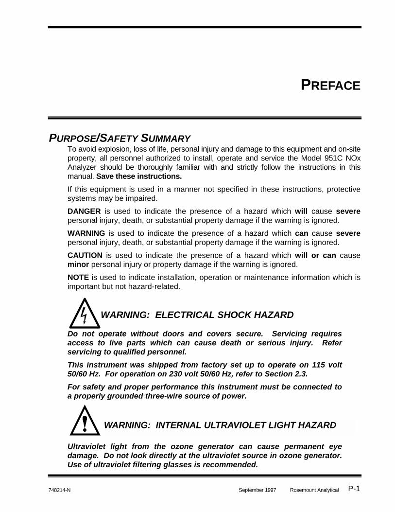
PURPOSE/SAFETY SUMMARYTo avoid explosion, loss of life, personal injury and damage to this equipment and on-siteproperty, all personnel authorized to install, operate and service the Model 951C NOxAnalyzer should be thoroughly familiar with and strictly follow the instructions in thismanual. Save these instructions.
If this equipment is used in a manner not specified in these instructions, protectivesystems may be impaired.
DANGER is used to indicate the presence of a hazard which will cause severepersonal injury, death, or substantial property damage if the warning is ignored.
WARNING is used to indicate the presence of a hazard which can cause severepersonal injury, death, or substantial property damage if the warning is ignored.
CAUTION is used to indicate the presence of a hazard which will or can causeminor personal injury or property damage if the warning is ignored.
NOTE is used to indicate installation, operation or maintenance information which isimportant but not hazard-related.
Do not operate without doors and covers secure. Servicing requiresaccess to live parts which can cause death or serious injury. Referservicing to qualified personnel.
This instrument was shipped from factory set up to operate on 115 volt50/60 Hz. For operation on 230 volt 50/60 Hz, refer to Section 2.3.
For safety and proper performance this instrument must be connected toa properly grounded three-wire source of power.
Ultraviolet light from the ozone generator can cause permanent eyedamage. Do not look directly at the ultraviolet source in ozone generator.Use of ultraviolet filtering glasses is recommended.
WARNING: ELECTRICAL SHOCK HAZARD
WARNING: INTERNAL ULTRAVIOLET LIGHT HAZARD
MODEL 951C NOX ANALYZER
Rosemount Analytical September 1997 748214-NP-2
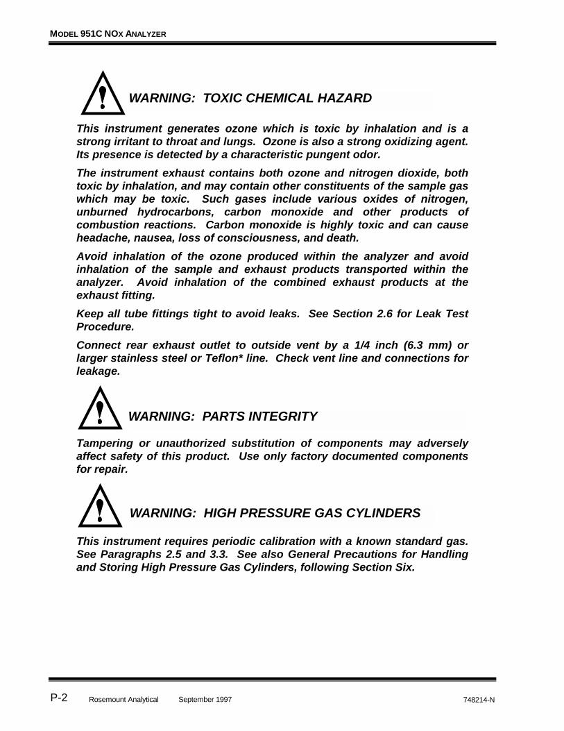
This instrument generates ozone which is toxic by inhalation and is astrong irritant to throat and lungs. Ozone is also a strong oxidizing agent.Its presence is detected by a characteristic pungent odor.
The instrument exhaust contains both ozone and nitrogen dioxide, bothtoxic by inhalation, and may contain other constituents of the sample gaswhich may be toxic. Such gases include various oxides of nitrogen,unburned hydrocarbons, carbon monoxide and other products ofcombustion reactions. Carbon monoxide is highly toxic and can causeheadache, nausea, loss of consciousness, and death.
Avoid inhalation of the ozone produced within the analyzer and avoidinhalation of the sample and exhaust products transported within theanalyzer. Avoid inhalation of the combined exhaust products at theexhaust fitting.
Keep all tube fittings tight to avoid leaks. See Section 2.6 for Leak TestProcedure.
Connect rear exhaust outlet to outside vent by a 1/4 inch (6.3 mm) orlarger stainless steel or Teflon* line. Check vent line and connections forleakage.
Tampering or unauthorized substitution of components may adverselyaffect safety of this product. Use only factory documented componentsfor repair.
This instrument requires periodic calibration with a known standard gas.See Paragraphs 2.5 and 3.3. See also General Precautions for Handlingand Storing High Pressure Gas Cylinders, following Section Six.
WARNING: PARTS INTEGRITY
WARNING: TOXIC CHEMICAL HAZARD
WARNING: HIGH PRESSURE GAS CYLINDERS

PREFACE
September 1997 Rosemount Analytical748214-N P-3
The ozone generator lamp contains mercury. Lamp breakage could resultin mercury exposure. Mercury is highly toxic if absorbed through skin oringested, or if vapors are inhaled.
HANDLE LAMP ASSEMBLY WITH EXTREME CARE.
If lamp is broken, avoid skin contact and inhalation in the area of the lampor the mercury spill.
Immediately clean up and dispose of the mercury spill and lamp residueas follows:
• Wearing rubber gloves and goggles, collect all droplets ofmercury by means of a suction pump and aspirator bottlewith long capillary tube. Alternatively, a commerciallyavailable mercury spill clean-up kit, such as J. T. Bakerproduct No. 4439-01, is recommended.
• Carefully sweep any remaining mercury and lamp debris intoa dust pan. Carefully transfer all mercury, lamp residue anddebris into a plastic bottle which can be tightly capped.Label and return to hazardous material reclamation center.
• Do not place in trash, incinerate or flush down sewer.
• Cover any fine droplets of mercury in non-accessiblecrevices with calcium polysulfide and sulfur dust.
This instrument’s internal pullout chassis is equipped with a safety stoplatch located on the left side of the chassis.
When extracting the chassis, verify that the safety latch is in its proper(counter-clockwise) orientation.
If access to the rear of the chassis is required, the safety stop may beoverridden by lifting the latch; however, further extraction must be donevery carefully to insure the chassis does not fall out of its enclosure.
If the instrument is located on top of a table or bench near the edge, andthe chassis is extracted, it must be supported to prevent toppling.
Failure to observe these precautions could result in personal injuryand/or damage to the product.
CAUTION: TOPPLING HAZARD
WARNING: TOXIC AND OXIDIZING GAS HAZARDS

MODEL 951C NOX ANALYZER
Rosemount Analytical September 1997 748214-NP-4
SPECIFICATIONS - LO RANGERANGES: 0 to 10, 0 to 25, 0 to 100, 0 to 250 ppm NOx
REPEATABILITY: within 0.1 ppm or ±1% of fullscale, whichever is greater
ZERO/SPAN DRIFT: less than ±0.1 ppm or ±1% of fullscale, whichever isgreater, in 24 hours at constant temperature
less than ±0.2 ppm or ±2% of fullscale, whichever isgreater, over any 10°C interval from 4 to 40°C (for ratechange of 10°C or less per hour)
RESPONSE TIME: 90% of fullscale in less than 1 minute
(ELECTRONIC + FLOW)
SENSITIVITY: less than 0.1 ppm or 1% of fullscale, whichever is greater
DETECTOR OPERATING
PRESSURE:atmospheric
TOTAL SAMPLE FLOW RATE: 1 Liter per minute at 20 psig
SAMPLE PRESSURE: 138 kPa (20 psig)
OZONE GENERATOR GAS: U.S.P. breathing-grade air
AMBIENT TEMPERATURE
RANGE:4 to 40°C (40 to 104°F)
ANALOG OUTPUT: Potentiometric: 0 to +5 VDC, 2000 ohm minimum load
Isolated Current: Field-selectable 0 to 20 or 4 to 20 mA,700 ohm maximum load
Display: Digital, 4-1/2 digit LCD, readout in engineeringunits, backlighted
POWER REQUIREMENTS: 115/230 VAC ±10%, 50/60 ±3 Hz, 570 W maximum
ENCLOSURE: General purpose for installation in weather-protectedareas
DIMENSIONS: 22.0 cm (8.7 in) H
48.3 cm (19 in.) W
48.3 cm (19 in.) D
WEIGHT 22.2 kg (49 lbs) approximate

PREFACE
September 1997 Rosemount Analytical748214-N P-5
SPECIFICATIONS - HI RANGERANGES: 0 to 100, 0 to 250, 0 to 1000, 0 to 2500 ppm NOx
REPEATABILITY: within 0.1 ppm or ±1% of fullscale, whichever is greater
ZERO/SPAN DRIFT: less than ±1.0 ppm or ±1% of fullscale, whichever isgreater, in 24 hours at constant temperature
less than ±2.0 ppm or ±2% of fullscale, whichever isgreater, over any 10°C interval from 4 to 40°C (for ratechange of 10°C or less per hour)
RESPONSE TIME: 90% of fullscale in less than 1 minute
(ELECTRONIC + FLOW)
SENSITIVITY: less than 0.1 ppm or 1% of fullscale, whichever is greater
DETECTOR OPERATING
PRESSURE:atmospheric
TOTAL SAMPLE FLOW RATE: 1 Liter per minute at 20 psig
SAMPLE PRESSURE: 138 kPa (20 psig)
OZONE GENERATOR GAS: U.S.P. breathing-grade air
AMBIENT TEMPERATURE
RANGE:4 to 40°C (40 to 104°F)
ANALOG OUTPUT: Potentiometric: 0 to +5 VDC, 2000 ohm minimum load
Isolated Current: Field-selectable 0 to 20 or 4 to 20 mA,700 ohm maximum load
Display: Digital, 4-1/2 digit LCD, readout in engineeringunits, backlighted
POWER REQUIREMENTS: 115/230 VAC ±10%, 50/60 ±3 Hz, 570 W maximum
ENCLOSURE: General purpose for installation in weather-protectedareas
DIMENSIONS: 22.0 cm (8.7 in) H
48.3 cm (19 in.) W
48.3 cm (19 in.) D
WEIGHT: 22.2 kg (49 lbs) approximate

MODEL 951C NOX ANALYZER
Rosemount Analytical September 1997 748214-NP-6
CUSTOMER SERVICE, TECHNICAL ASSISTANCE AND FIELD SERVICEFor order administration, replacement Parts, application assistance, on-site or factoryrepair, service or maintenance contract information, contact:
Rosemount Analytical Inc.Process Analytical DivisionCustomer Service Center
1-800-433-6076
RETURNING PARTS TO THE FACTORYBefore returning parts, contact the Customer Service Center and request a ReturnedMaterials Authorization (RMA) number. Please have the following information whenyou call: Model Number, Serial Number, and Purchase Order Number or SalesOrder Number.
Prior authorization by the factory must be obtained before returned materials will beaccepted. Unauthorized returns will be returned to the sender, freight collect.
When returning any product or component that has been exposed to a toxic,corrosive or other hazardous material or used in such a hazardous environment, theuser must attach an appropriate Material Safety Data Sheet (M.S.D.S.) or a writtencertification that the material has been decontaminated, disinfected and/or detoxified.
Return to:
Rosemount Analytical Inc.4125 East La Palma Avenue
Anaheim, California 92807-1802
TRAININGA comprehensive Factory Training Program of operator and service classes isavailable. For a copy of the Current Operator and Service Training Schedule contactthe Technical Services Department at:
Rosemount Analytical Inc.Phone: 1-714-986-7600FAX: 1-714-577-8006
DOCUMENTATIONThe following Model 951C NOx Analyzer instruction materials are available.Contact Customer Service or the local representative to order.
748214 Instruction Manual (this document)

PREFACE
September 1997 Rosemount Analytical748214-N P-7
COMPLIANCESThis product satisfies all obligations of all relevant standards of the EMC frameworkin Australia and New Zealand.
N96

MODEL 951C NOX ANALYZER
Rosemount Analytical September 1997 748214-NP-8
NOTES

CONDENSED STARTUP AND CALIBRATION
PROCEDURE
September 1997 Rosemount Analytical748214-N P-9
The following summarized instructions on startup and calibration are intended foroperators already familiar with the analyzer.
For initial startup, refer to detailed instructions provided in Section 3.
1. Set slider switch on the Signal Board (Figure 3-2) to 250 ppm (see Figure 3-2).
2. Apply power to the analyzer. The analyzer will now require approximately one to twohours for temperature equilibrium before being ready for calibration.
3. Verify that the pressure regulator on the cylinder of zero gas (nitrogen or air) or samplegas is set for supply pressure of 10 to 17 psig.
4. Verify that the pressure regulator on the cylinder of air (ozonator supply) is set forsupply pressure of 20 to 25 psig.
5. Establish correct pressure of sample gas:
a. Supply sample gas to rear-panel SAMPLE inlet at 10 to 17 psig (normally 15psig).
b. Adjust SAMPLE Back Pressure Regulator so that SAMPLE Pressure Gaugeindicates the value appropriate to the desired operating range (normal operatingpressure is 3 to 5 psig). See Figure 3-1.
6. Establish correct pressure of zero gas:
a. Supply zero gas to rear panel SAMPLE inlet and set to 15 psig.
b. Note reading on SAMPLE Pressure Gauge. It should be the same as in Step 5b.If not, adjust output pressure regulator on the zero gas cylinder as required.
7. Establish correct pressure of upscale standard gas:
a. Supply upscale standard gas to rear panel SAMPLE inlet.
b. Note reading on SAMPLE Pressure Gauge. It should be the same as in Step 6b.If not, adjust output regulator on cylinder of upscale standard gas as required.

MODEL 951C NOX ANALYZER
Rosemount Analytical September 1997 748214-NP-10
Note
Supply pressure for sample, upscale standard gas and zero air must bethe same. If not, the readout will be in error.
8. Zero Calibration.
a. Set PPM RANGE Switch for range to be used for sample analysis. Set SPANControl at normal operating setting, if known, or at about mid-range if normalsetting is not known.
b. Supply zero gas to rear panel SAMPLE inlet.
c. Adjust ZERO Control for reading of zero on meter or recorder.
9. Upscale Calibration.
a. Set PPM RANGE Switch at setting appropriate to the particular span gas.
b. Supply upscale standard gas of accurately known NOx content to rear panelSAMPLE inlet.
c. Adjust SPAN Control so that reading on meter or recorder is equal to the knowparts-per-million concentration of NOx in the span gas.
Note
It is the responsibility of the user to measure efficiency of the NO2-to-NOconverter during initial startup, and thereafter at intervals appropriate tothe application, normally once a month.
1INTRODUCTION
Rosemount Analytical748214-N September 1997 1-1
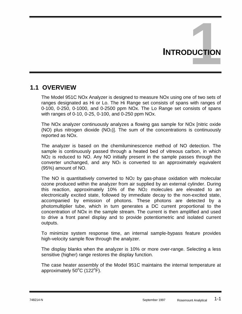
1.1 OVERVIEW
The Model 951C NOx Analyzer is designed to measure NOx using one of two sets ofranges designated as Hi or Lo. The Hi Range set consists of spans with ranges of0-100, 0-250, 0-1000, and 0-2500 ppm NOx. The Lo Range set consists of spanswith ranges of 0-10, 0-25, 0-100, and 0-250 ppm NOx.
The NOx analyzer continuously analyzes a flowing gas sample for NOx [nitric oxide(NO) plus nitrogen dioxide (NO2)]. The sum of the concentrations is continuouslyreported as NOx.
The analyzer is based on the chemiluminescence method of NO detection. Thesample is continuously passed through a heated bed of vitreous carbon, in whichNO2 is reduced to NO. Any NO initially present in the sample passes through theconverter unchanged, and any NO2 is converted to an approximately equivalent(95%) amount of NO.
The NO is quantitatively converted to NO2 by gas-phase oxidation with molecularozone produced within the analyzer from air supplied by an external cylinder. Duringthis reaction, approximately 10% of the NO2 molecules are elevated to anelectronically excited state, followed by immediate decay to the non-excited state,accompanied by emission of photons. These photons are detected by aphotomultiplier tube, which in turn generates a DC current proportional to theconcentration of NOx in the sample stream. The current is then amplified and usedto drive a front panel display and to provide potentiometric and isolated currentoutputs.
To minimize system response time, an internal sample-bypass feature provideshigh-velocity sample flow through the analyzer.
The display blanks when the analyzer is 10% or more over-range. Selecting a lesssensitive (higher) range restores the display function.
The case heater assembly of the Model 951C maintains the internal temperature atapproximately 50oC (122oF).

MODEL 951C NOX ANALYZER
Rosemount Analytical 748214-NSeptember 19971-2
1.2 APPLICATIONS
The Model 951C Analyzer has specific applications in the following areas:
• Oxides of nitrogen (NOx) emissions from the combustion of fossil fuels in:
Vehicle engine exhaust
Incinerators
Boilers
Gas appliances
Turbine exhaust
• Nitric acid plant emissions
• Ammonia in pollution control equipment (with converter)
• Nitric oxide emissions from decaying organic material (i.e., landfills)
2INSTALLATION
Rosemount Analytical748214-N September 1997 2-1
2.1 UNPACKING
Carefully examine the shipping carton and contents for signs of damage. Immediatelynotify the shipping carrier if the carton or its contents are damaged. Retain the cartonand packing material until the instrument is operational.
2.2 LOCATION
See drawing 654063 for Outline and Mounting dimensions.
Install analyzer in a clean area, free from moisture and excessive vibration, at a stabletemperature within 4 to 40°C.
The analyzer should be mounted near the sample source to minimizesample-transport time.
A temperature control system maintains the internal temperature of analyzer at 50°C(122°F) to ensure proper operation over an ambient temperature range of 4°C to 40°C(40°F to 110°F). Temperatures outside these limits necessitate use of specialtemperature-controlling equipment or environmental protection. Also, the ambienttemperature should not change at a rate exceeding 10°C/hr.
The cylinders of air and span gas should be located in an area of constant ambienttemperature (±10°C).
2.3 VOLTAGE REQUIREMENTS
For safety and proper performance this instrument must be connected to aproperly grounded three-wire source of power.
This instrument was shipped from the factory set up to operate on 115 VAC, 50/60 Hzelectric power. For operation on 230 VAC, 50/60 Hz, position voltage select switchesS1, S2, S3 (located on the Power Supply Board, Figure 2-1) and S3 (located on theTemperature Control Board, Figure 2-2) must be in the 230 VAC position.
WARNING: ELECTRICAL SHOCK HAZARD

MODEL 951C NOX ANALYZER
Rosemount Analytical 748214-NSeptember 19972-2
Refer to Figure 2-4. Remove the 6.25 A fuse (P/N 902413) and replace with the 3.15A fuse (P/N 898587) provided in the shipping kit.
2.4 ELECTRICAL CONNECTIONS
The power and output (recorder and current) cable glands are supplied loose in theshipping kit to allow cable installation to connectors or terminal strips.
Cable Gland Part No.
Power 899330Recorder 899329
Remove rear cover to access terminals. Route each cable through the cable glandand connect to the appropriate connector or terminal strip, tighten the gland.
2.4.1 LINE POWER CONNECTIONS
Refer to Figures 2-3, 2-4 and drawing 654063. If this instrument is located on a benchor table top or is installed in a protected rack, panel or cabinet, power may beconnected via a 3-wire flexible power cord, minimum 18 AWG (max. O.D. 0.480", min.O./D. 0.270"), through the hole labeled POWER, utilizing connector gland (P/N899330) provided.
Route the power cable through the cable gland and connect the leads to TB1. Tightenthe cable gland adequately to prevent rotation or slippage of the power cable. Sincethe rear terminals do not slide out with the chassis, no excess power cable slack isnecessary.
The following power cord and/or support feet (for bench top use) are available:
• Power Cord 634061
• North American power cord set (10 foot)
• Enclosure Support Kit 634958
• Enclosure support feet (4)
• Power Cord/Enclosure Support Kit 654008
• North American power cord set (10 foot)
• Enclosure support feet (4)
If the instrument is permanently mounted in an open panel or rack, use electricalmetal tubing or conduit.

INSTALLATION
Rosemount Analytical748214-N September 1997 2-3
FIGURE 2-1. POWER SUPPLY BOARD VOLTAGE SELECT SWITCHES
FIGURE 2-2. TEMPERATURE CONTROL BOARD
CS
115V115V 115V
C10
115V
230VS1
115V
230VS2
115V
230VS3
J5
1
J3
1
J201
655340 POWER SUPPLY BD
115V
115V
230V
115V
115V
230V
115V
115V
230VS1S2 S3
Set switch window for voltage required.
Set switch window for voltage required.
S3
SENSORJ18
POWERSUPPLY
J11
POWERLINEJ5
J19TEST
T.I.F. HEATERJ17 115
230S3
U2
1
2
3
U1
1
1 2 1 2 31
E
B
CQ3
CRR13R2R1Q1
G
A
K
R3R4
C1
Q2
C
B E
CR1
C2 R10 R11 R7 R8 R17R16 R12 CR2
C3
R6
R9 R5
R15 R14
C4 3 2 1
TEMP CONTROL BD
+
AR1
115
R18R19
MODEL 951C NOX ANALYZER
Rosemount Analytical 748214-NSeptember 19972-4
2.4.2 POTENTIOMETRIC RECORDER CONNECTIONS
Refer to Figures 2-3, 2-4 and drawing 654063. Potentiometric recorder connec-tionsare made on the rear panel. Route the potentiometric recorder cable through thecable gland in the hole labeled RECORDER OUTPUT and connect to VOLTOUTPUT terminals.
Potentiometric recorder cable specifications are as follows:
• Distance from recorder to analyzer: 1000 feet (305 meters) maximum
• Input impedance: Greater than 2000 ohms
• Cable (user supplied): Two-conductor, shielded, min. 20 AWG
• Voltage output: 0 to +5 VDC
2.4.3 CURRENT RECORDER CONNECTIONS
Refer to Figures 2-3, 2-4 and drawing 654063. Current recorder connections aremade on the rear panel. Route the current recorder cable through the cable gland inthe hole labeled RECORDER OUTPUT and connect to CUR OUTPUT terminals
Current recorder interconnection cable specs are as follows:
• Distance the recorder from analyzer: 3000 feet (915 meters).maximum
• Load resistance: Less than 700 Ohms.
• Cable (user supplied): Two-conductor, shielded, min. 20 AWG
As supplied by the factory, the current output produces a zero of 4 mA. The currentoutput may be adjusted to produce a zero of 0 mA as follows:
1. Zero the instrument as in Section 3.4.
2. Adjust R23, the zero-adjust potentiometer on the Power Supply Board, to produce0 mA current output.
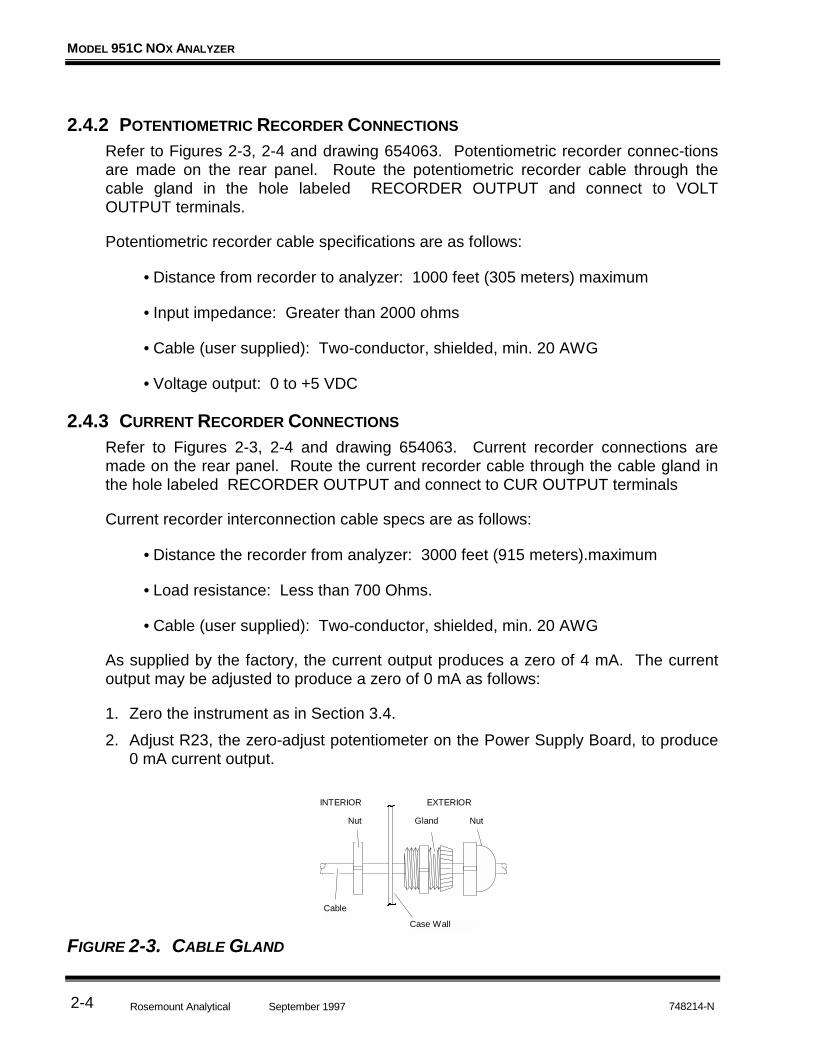
FIGURE 2-3. CABLE GLAND
Case Wall
Cable
Nut Gland Nut
INTERIOR EXTERIOR

INSTALLATION
Rosemount Analytical748214-N September 1997 2-5
EXHAUSTAIRIN
20 PSI (138 kPa)NOMINAL
RECORDEROUTPUT
POWER
+ - G + -
CUROUTPUT
VOLTOUTPUT
L1/HOTL2/NEUT
GND
SAMPLEIN
10 PSI - 17 PSI(70 kPa - 120 kPa)
RecorderConnections
AC PowerConnections
Current OutputConnections
FUSE
Fuse
FIGURE 2-4. REAR VIEW OF MODEL 951C (COVER REMOVED)
2.5 GAS REQUIREMENTS
The instrument requires two gases normally supplied from cylinders. They are:
AIR (U.S.P. BREATHING GRADE)This is used as both (a) an oxygen source for generation of the ozone required for thechemiluminescence reaction, and (b) a standard gas for zero calibration (nitrogen canalso be used). Gas for each purpose must be supplied from a separate cylinder due todifferent pressure requirements at ozonator and zero inlets.
SPAN GAS
This is a standard gas of accurately known composition, used to set an upscalecalibration point. The usual span gas is NO or NO2 in a background of nitrogen.
This instrument requires periodic calibration with a known standard gas. See Paragraphs 2.5 and 3.3. See also General Precautions for Handlingand Storing High Pressure Gas Cylinders, following Section Six.
WARNING: HIGH PRESSURE GAS CYLINDERS

MODEL 951C NOX ANALYZER
Rosemount Analytical 748214-NSeptember 19972-6
Note
For maximum calibration accuracy, the concentration of NO in the spangas should be similar to that in the sample gas. Also, the span gas shouldbe supplied to the rear panel SAMPLE inlet at the same pressure as thesample gas. To ensure constant pressure, a pressure regulator may beutilized immediately upstream from the SAMPLE inlet.
Each gas used should be supplied from a tank or cylinder equipped with a clean,non-corrosive type, two-stage regulator. In addition, a shut-off valve is desirable.Install the gas cylinders in an area of relatively constant ambient temperature.
2.6 SAMPLE REQUIREMENTS
The sample must be clean and dry before entering the analyzer. In general, beforeadmission to the analyzer, the sample should be filtered to eliminate particles largerthan two microns and have a dew point below 90°F (32°C). The factory can providetechnical assistance if desired.
Proper supply pressure for sample, zero and span gases for the Model 951C is20 psig (138 kPa).
2.7 GAS CONNECTIONS
This instrument generates ozone which is toxic by inhalation and is astrong irritant to throat and lungs. Ozone is also a strong oxidizing agent. Its presence is detected by a characteristic pungent odor.
The instrument exhaust contains both ozone and nitrogen dioxide, bothtoxic by inhalation, and may contain other constituents of the sample gaswhich may be toxic. Such gases include various oxides of nitrogen,unburned hydrocarbons, carbon monoxide and other products ofcombustion reactions. Carbon monoxide is highly toxic and can causeheadache, nausea, loss of consciousness, and death.
Avoid inhalation of the ozone produced within the analyzer and avoidinhalation of the sample and exhaust products transported within theanalyzer. Avoid inhalation of the combined exhaust products at the exhaustfitting.
Keep all tube fittings tight to avoid leaks. See Section 2.8 for Leak TestProcedure.
Connect rear exhaust outlet to outside vent by a 1/4 inch (6.3 mm) or largerstainless steel or Teflon line. Check vent line and connections for leakage.
WARNING: TOXIC AND OXIDIZING GAS HAZARDS

INSTALLATION
Rosemount Analytical748214-N September 1997 2-7
1. Remove plugs and caps from all inlet and outlet fittings. (See Figure 2-4.)
2. Connect EXHAUST outlet to external vent via tubing with O.D. of 1/4-inch (6.3 mm)or larger. Use only stainless steel or Teflon tubing.
3. Connect external lines from ozonator air and sample sources to corresponding rearpanel inlet ports. For sample line, stainless steel tubing is recommended.
4. Adjust regulator on ozonator air cylinder for output pressure of 20 to 25 psig (138to 172 kPa). At least 20 psig should be present at rear of analyzer.
5. Supply sample gas to rear panel SAMPLE inlet at appropriate pressure: 20 psig(138 kPa). The nominal input pressure is 20 psig (138 kPa).
2.8 LEAK TEST
The following test is designed for sample pressure up to 5 psig (35 kPa).
1. Supply air or inert gas such as nitrogen at 5 psig (35 kPa) to analyzer sample andair input fittings.
2. Seal off analyzer exhaust fitting with a tube cap.
3. Use a suitable test liquid such as SNOOP (P/N 837801) to detect leaks. Cover allfittings, seals, or possible leak sources.
4. Check for bubbling or foaming which indicates leakage, and repair as required. Any leakage must be corrected before introduction of sample and/or application ofelectrical power.

MODEL 951C NOX ANALYZER
Rosemount Analytical 748214-NSeptember 19972-8
NOTES

3INITIAL STARTUP AND OPERATION
Rosemount Analytical748214-N September 1997 3-1
ConverterTemp Check
(S4)
Range SelectSwitch (S1)
SIGNAL BOARD(See Figure 3-2)
Ozone Indicator Lamp(Signal Board DS2)
Span Control(Signal Board R101)
Zero Control(Signal Board R100)
Display(Signal Board DS1)
Signal (R20)
Cal (R18)
Gain (R24)
Adj. (R8)
TP1 TP2
Current OutputSpan (R20)
Current OutputZero (R23)
ConvertorHeater(R9)
PMTHigh Voltage(R30)
Voltage Select(S2)
Voltage Select(S1)
Voltage Select(S3)
CASE HEATER TEMPERATURE CONTROL ASSEMBLY(See Figure 6-4)TEMPERATURE CONTROL BOARD (See Figure 2-2)
Voltage Select(S3)
SAMPLE PRESSUREGAUGE
SAMPLE PRESSUREREGULATOR(Adjustment Knob)
POWER SUPPLY BOARD(See Figure 3-3)
3.1 FRONT PANEL INDICATORS AND CONTROLS
3.1.1 DISPLAY
The display is a 4-digit liquid crystal device which always displays NOx concentrationin parts-per-million. See Figure 3-1.
3.1.2 RANGE SELECTION
The Model 951C has eight customer selectable ranges, four LO ranges (10 ppm, 25ppm, 100 ppm and 250 ppm) and four HI ranges (100 ppm, 250 ppm 1000 ppm and2500 ppm). The range is selected by positioning the RANGE Switch (S1) and thethree jumpers on the Signal Board to the desired range controlling the recorder output. Refer to Figure 3-2.
The display blanks for values 10% in excess of the range maximum. Moving theswitch to the left selects a higher fullscale value and restores the display.
FIGURE 3-1. MODEL 951C CONTROLS, INDICATORS AND ADJUSTMENTS

MODEL 951C NOX ANALYZER
Rosemount Analytical 748214-NSeptember 19973-2
3.1.3 SAMPLE PRESSURE GAUGE
The internal SAMPLE pressure (nominally 4 psig, 28 kPa) is adjusted by rotation ofthe Sample Pressure Regulator. See Figure 3-1.
3.1.4 OZONE PRESSURE
The OZONE pressure is determined by the pressure regulator of the air supplycylinder. A nominal pressure of 20 to 25 psig (138 to 172 kPa) is recommended. Proper operation is indicated when the front panel OZONE indicator lamp is lit.
Note
If ozone lamp does not light, increase pressure slightly by adjustingpressure regulator control on the air cylinder.
3.1.5 ZERO AND SPAN POTENTIOMETERS
See Figures 3-1 and 3-2. Screwdriver access holes through the front panel allowadjustments of the ZERO and SPAN potentiometers (R100 and R101 on SignalBoard.
3.1.6 OZONE INTERLOCK
The ozone-producing UV lamp will not ignite or stay lit unless adequate air pressure ispresent at the AIR inlet (see Figure 2-4). Nominal set point pressure is 20 to 25 psig.
3.2 STARTUP PROCEDURE
The following are detailed instructions on startup and calibration.
1. Supply electrical power to the analyzer. The analyzer will require approximately twohours for temperature equilibration before calibration.
2. On Signal Board, Figure 3-2, set PPM RANGE Switch (S1) to 250 ppm.
3. Establish correct pressure for air by the following:
a. Adjust OZONE Pressure Regulator so that OZONE Pressure Gauge indicates20 to 25 psig (138 to 172 kPa).
b. To establish correct pressure of zero gas, supply zero gas to rear panel SAMPLEinlet. Note reading on internal SAMPLE Pressure Gauge. It should be the same asthe nominal 4 psig (28 kPa) SAMPLE pressure indicated on the internal SAMPLEpressure gauge. This should remain constant when the analyzer input SAMPLE isswitched from calibration gas standard to a zero gas standard. This may be assuredby setting the delivery from the SAMPLE and the zero gas cylinder of span gascylinder to the same value of delivery pressure, nominally 20 psig (138 kPa). If not,adjust output pressure regulator on zero gas cylinder as required.

INITIAL STARTUP AND OPERATION
Rosemount Analytical748214-N September 1997 3-3
FIGURE 3-2. SIGNAL BOARD
4. Establish correct pressure of sample gas by the following:a. Supply sample gas to rear panel SAMPLE inlet.b. Adjust SAMPLE Backpressure Regulator so internal SAMPLE Pressure Gauge
indicates the value appropriate to the desired operating range.
Note
Inability to obtain a flow of one liter per minute at the EXHAUST outletusually indicates insufficient sample supply pressure at the SAMPLE inlet.Use a 2400 cc flowmeter (i.e., Brooks P/N 1350) at the EXHAUST outlet tomeasure flow.
5. Establish correct flow of upscale standard gas by the following:a. Supply upscale standard gas to rear panel SAMPLE inlet.
b. Note reading on internal SAMPLE Pressure Gauge. It should be the same as inStep 3b.
Note
Supply pressures for sample and upscale standard gases must be thesame. Otherwise, readout will be in error.
The analyzer is now ready for calibration.
J1
10 10025 250
S1
CS
ADJ. GAIN SIG. CAL.
E3DP SELECT
E4
E5
TP6 TP5 TP4 TP3 TP2 TP1
E1 E2R39R40R23
DS1
DS2
C
SIGNAL IN
E6E7
K3R28
R29
C14
R34
C15
AR4
RP3
1
R37
R38
C12
C16
AR6
AR5
RP2
R101
CWSCCW
SPAN
R22
R100
CWSCCW
ZERO
R42
U7
C13
+
CR23
R35
R36 Q3
E
B
C
R17
C9 C5 R14 R12 U2
C8
R13
C6
C10
U3
+ R16
R15
R31
R30 AR1
R32 R33
Q2E
B
C
K1
K2
VR1
CR1
CR2
CR13
CR14
CR12
CR11
CR10
CR9
CR8
R19
R21
R1
R2
R3
R4
R5
R6
R7
R8
R9
R10
R11
U1RP1
1
R27 R41RANGE
J3
CR3
CR4
CR5
CR6
CR7
C7
C11
+CR22
CR21
CR20
CR19
CR18
CR16 CR17
CR15
C17
+
T1R25 R24 R20 R18
C3
C2
C1
Q1
C E
B
AR2 AR3
C4
654050 SIGNAL CONTROL BD
E1 E2
E4
E3
E5
E1 E2
E4
E3
E5
Lo Hi
E7
E6
E7
E6
Lo Hi
10 10025 250
S1
HiRange
(S1 pos)ppm
Fullscale
1 (10) 1002 (25) 2503 (100) 10004 (250) 2500
LoRange
(S1 pos)ppm
Fullscale
1 (10) 102 (25) 253 (100) 1004 (250) 250
R101 - SPAN Potentiometer R100 - ZERO Potentiometer
MODEL 951C NOX ANALYZER
Rosemount Analytical 748214-NSeptember 19973-4
TP3 TP4
VR9
U7
C13
VR5
OGI
C12
I G O
VR4
1 2 3 4
U8CR8
C14+
C15+
R26
CR7+
+VR6 IGO
TP14 TP15
R22R24
R25R21
R19
R23
OUTPUTZERO
CURRENTSPAN
R20
J13
J14
CS
C26
+
1 2
J11Q12
E C
E
Q24B
E
C
C22
U9
CR13
R53
R40
R42
R49R47
E
B
Q10
C
Q8G
AC
C
B E
Q9
R54
R4C23
+
R3
CR1
THERMOCOOLER
TP1
R9
CONVHTR
RMTHV
R16
S4
R6
BC
E
Q2
Q1K
G
A
R14
CONVTEMP
CHECK
TP13
CR4CONVERTOR
R4
R2
TP2 TP5 TP6 TP7 TP8
R3
R7
R18 R12 R11
C8
R13J19AR1
Q3
E
C
B
C9
C7+
CR5
R15
CR6
R79
R77
R78
Q15 E
C
B
U23
U1
R6
C16
R27
C17
C20+
R28
C18
R64
Q4
EBC
R35
R34R65
R66Q5
R73
CR16
AR2
C19
R74
U22
R36
R32
R31
R29
CR10
CR9
R37CR11
E
R38R76
R75
CR24
R70
U20R71
R68
R67
CR23
U21
CR2
B
Q14
E C
R62R63
R39
J19R72R69RP11
B
1
J7
2
E
C
BQ7C
B
Q6
R33
CR17
A
O
I
C3
CR20+
C4 CR1
VR3
C5
VR1
VR2
+
+
C2 +
C1
+
+ +
C29
+
+
VR7
G I O
CR18+
C25+
CR2
+
1
J6
R61
CR19
+C27
CR3
R1K1
VR8O G I
C28
+
C6
EB
C
Q13
R60R59
R56R57
R58
J17
1 J2
1
J1
1
U2
R17R18
C10
115V
115V
230VS1
115V
115V
230VS2
115V
115V
230VS3
J5
1
J3
1
J201
J181
R68
R55
CR12R51
R45R80R81R82
J8
1
J12
1
J4
1
J15
1
J16
1
J91
TP9 TP10 TP11 TP12
C21
+R48R46R44R43R41
CR14
+C11
R30
CR15
THERMOCOOLER
TP1
R9
CONVHTR
PMTHV
S4
CONVTEMP
CHECK
TP13
CR4CONVERTOR
TP2 TP5 TP6 TP7 TP8
C8R23
OUTPUTZERO
CURRENTSPAN
TP14 TP15
R20
655340 POWER SUPPLY BD
115V
115V
230V
S1
115V
115V
230V
S2
115V
115V
230V
S3
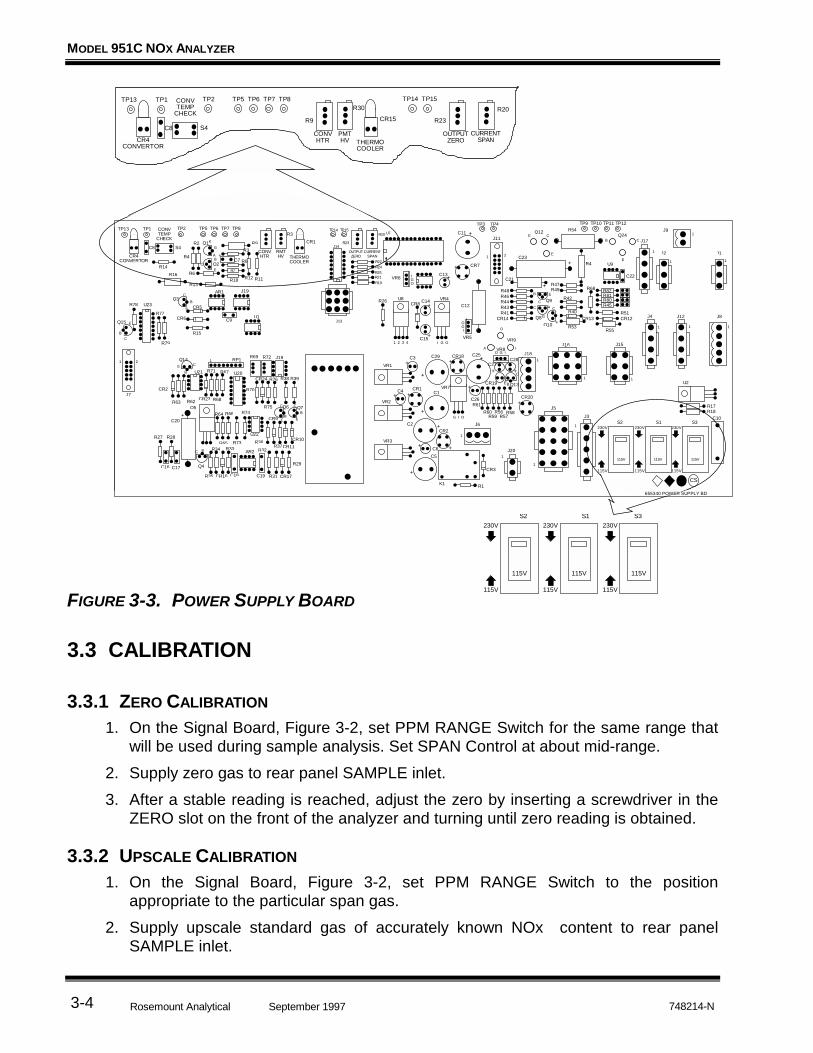
FIGURE 3-3. POWER SUPPLY BOARD
3.3 CALIBRATION
3.3.1 ZERO CALIBRATION
1. On the Signal Board, Figure 3-2, set PPM RANGE Switch for the same range thatwill be used during sample analysis. Set SPAN Control at about mid-range.
2. Supply zero gas to rear panel SAMPLE inlet.
3. After a stable reading is reached, adjust the zero by inserting a screwdriver in theZERO slot on the front of the analyzer and turning until zero reading is obtained.
3.3.2 UPSCALE CALIBRATION
1. On the Signal Board, Figure 3-2, set PPM RANGE Switch to the positionappropriate to the particular span gas.
2. Supply upscale standard gas of accurately known NOx content to rear panelSAMPLE inlet.
INITIAL STARTUP AND OPERATION
Rosemount Analytical748214-N September 1997 3-5
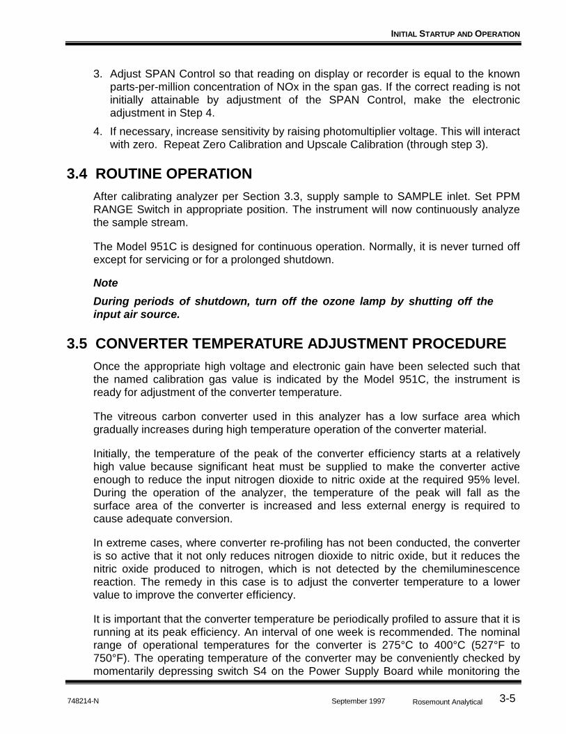
3. Adjust SPAN Control so that reading on display or recorder is equal to the knownparts-per-million concentration of NOx in the span gas. If the correct reading is notinitially attainable by adjustment of the SPAN Control, make the electronicadjustment in Step 4.
4. If necessary, increase sensitivity by raising photomultiplier voltage. This will interactwith zero. Repeat Zero Calibration and Upscale Calibration (through step 3).
3.4 ROUTINE OPERATION
After calibrating analyzer per Section 3.3, supply sample to SAMPLE inlet. Set PPMRANGE Switch in appropriate position. The instrument will now continuously analyzethe sample stream.
The Model 951C is designed for continuous operation. Normally, it is never turned offexcept for servicing or for a prolonged shutdown.
Note
During periods of shutdown, turn off the ozone lamp by shutting off theinput air source.
3.5 CONVERTER TEMPERATURE ADJUSTMENT PROCEDURE
Once the appropriate high voltage and electronic gain have been selected such thatthe named calibration gas value is indicated by the Model 951C, the instrument isready for adjustment of the converter temperature.
The vitreous carbon converter used in this analyzer has a low surface area whichgradually increases during high temperature operation of the converter material.
Initially, the temperature of the peak of the converter efficiency starts at a relativelyhigh value because significant heat must be supplied to make the converter activeenough to reduce the input nitrogen dioxide to nitric oxide at the required 95% level.During the operation of the analyzer, the temperature of the peak will fall as thesurface area of the converter is increased and less external energy is required tocause adequate conversion.
In extreme cases, where converter re-profiling has not been conducted, the converteris so active that it not only reduces nitrogen dioxide to nitric oxide, but it reduces thenitric oxide produced to nitrogen, which is not detected by the chemiluminescencereaction. The remedy in this case is to adjust the converter temperature to a lowervalue to improve the converter efficiency.
It is important that the converter temperature be periodically profiled to assure that it isrunning at its peak efficiency. An interval of one week is recommended. The nominalrange of operational temperatures for the converter is 275°C to 400°C (527°F to750°F). The operating temperature of the converter may be conveniently checked bymomentarily depressing switch S4 on the Power Supply Board while monitoring the

MODEL 951C NOX ANALYZER
Rosemount Analytical 748214-NSeptember 19973-6
resistance across terminals TP1 and TP2. Table 3-1 allows for conversion of theobserved resistance to the operating temperature for the converter.
Follow this procedure to optimize the operating temperature of the converter:
1. Power instrument and allow it to stabilize at operating temperature (one to twohours). Measure the operating temperature of the converter by the techniquedescribed above. Note the value for future reference.
2. Admit a calibration gas of known (NO2) concentration into the analyzer and notethe concentration value determined when the full response has been achieved.
3. Refer to Figure 3-3. Turn the converter temperature adjust potentiometer R9, onthe Power Supply Board one turn counterclockwise from the setting established atthe factory, and allow fifteen minutes for operation at the new lower temperaturesetpoint. Recheck the response and note the value for later use.
4. Increase the temperature of the converter by rotating the converter temperatureadjust potentiometer, R9, one quarter turn clockwise, wait fifteen minutes forthermal equilibrium and then re-measure the NO2 calibration gas value. Note itsvalue. Repeat this procedure of one quarter turn adjustments of the potentiometer,waiting for thermal stability and determination of the calibration gas value untileither a 95% value is obtained or the final one quarter turn adjustment gives anefficiency increase of less than one percent.
5. Decrease the temperature of converter operation by rotating the convertertemperature adjust potentiometer one eighth of a turn counterclockwise. Thisplaces the converter at a temperature suitable for low ammonia interference andefficient NO2 conversion. Re-measure the indicated converter temperature andcompare it to the initially recorded value.
TEMPERATURE(°C)
RESISTANCE(Ohms)
0 400
25 438
100 552
200 704
250 780
300 856
350 932
400 1008
450 1084
TABLE 3-1. RESISTANCE OF CONVERTER TEMPERATURE SENSOR VS. TEMPERATURE

INITIAL STARTUP AND OPERATION
Rosemount Analytical748214-N September 1997 3-7
Note
Converter temperature is not a direct measure of converter efficiency.Temperature measurement is for reference purposes only.
3.6 MEASUREMENT OF CONVERTER EFFICIENCY
It is the responsibility of the user to measure efficiency of the NO2-to-NO converterduring initial startup, and thereafter at intervals appropriate to the application (normallyonce a month).
The above procedure optimizes the operating temperature of the converter. It alsoserves as an efficiency check if the concentration of NO2 in the calibration gas isdocumented accurate relative to National Institute of Standards and Technology(NIST) Reference Materials. If the concentration of the nitrogen dioxide calibration gasis not known accurately, this procedure still serves to adequately provide the correctconverter operating temperature.
If the only available known standard is the nitric oxide calibration standard, thefollowing procedure may be performed. This procedure checks converter efficiencythrough the utilization of gas-phase oxidation of nitric oxide into nitrogen dioxide overa range of nitrogen dioxide concentrations. This technique is abstracted and adaptedfrom 40 CFR, Pt. 60, App. A, Method 20, Paragraph 5.6.
1. Select the appropriate instrument range.
2. Admit a nitric oxide in nitrogen NIST traceable calibration gas of a value between45% and 55% of the instrument range selected to a clean, evacuated, leak tightTedlar bag. Dilute this gas approximately 1:1 with a 20.9% oxygen, purified air.
3. Immediately attach the bag outlet to the input of the pump supplying pressurizedgas to the analyzer. It is important to use a sample delivery pump which does notconsume nitrogen dioxide as it delivers sample to the analyzer. Losses of nitrogendioxide in the pump will be reported as converter inefficiency.
4. Operate the analyzer and continue to sample the diluted nitric oxide sample for aperiod of at least thirty minutes. If the nitrogen dioxide to nitric oxide conversion isat the 100% level, the instrument response will be stable at the highest valuenoted.
5. If the response at the end of the thirty minute period decreases more than 2.0percent of the highest peak value observed, the system is not acceptable andcorrections must be made before repeating the check. If it is determined thatobserved subnormal conversion efficiencies are real, and not due to errorsintroduced by nitrogen dioxide consumption in the sample pump or other parts ofthe sample handling system, verify that the converter is peaked at the optimumtemperature before replacing with a new converter.
MODEL 951C NOX ANALYZER
Rosemount Analytical 748214-NSeptember 19973-8
3.7 RECOMMENDED CALIBRATION FREQUENCY
After initial startup or startup following a shutdown, the analyzer requires about twohours for stabilization before it is ready for calibration. Maximum permissible intervalbetween calibrations depends on the analytical accuracy required, and thereforecannot be specified. It is recommended that initially the instrument be calibrated atleast once every 8 hours. This practice should continue until experience indicates thatsome other interval is more appropriate.

4THEORY
Rosemount Analytical748214-N September 1997 4-1
4.1 NITRIC OXIDE DETERMINATION BY CHEMILUMINESCENCEMETHOD
The chemiluminescence method for detection of nitric oxide (NO) is based on itsreaction with ozone (O3) to produce nitrogen dioxide (NO2) and oxygen (O2). Some ofthe NO2 molecules thus produced are initially in an electronically excited state (NO2*).These revert immediately to the ground state, with emission of photons (essentiallyred light).
The reactions involved are:
NO + O3 → NO2* + O2
NO2* → NO2 + Red Light
As NO and O3 mix in the reaction chamber, the intensity of the emitted red light isproportional to the concentration of NO.
(Any NO2 initially present in the sample is reduced to NO by a heated bed of vitreouscarbon through which the sample is passed before being routed to the reactionchamber.)
The intensity of the emitted red light is measured by a photomultiplier tube (PMT),which produces a current of approximately 3 X 10⁻⁹ amperes per part-per-million of NOin the reaction chamber.
4.2 ANALYZER FLOW SYSTEM
The analyzer flow system is shown in drawing 654090. Its basic function is to deliverregulated flows of sample, calibration gas, or zero gas and ozonized air to the reactionchamber. The discharge from the reaction chamber flows from the analyzer via theEXHAUST outlet.
4.2.1 FLOW OF SAMPLE, STANDARD GAS OR ZERO GAS TO REACTION CHAMBER
Suitably pressurized sample, standard gas or zero gas is supplied to the rear panelSAMPLE inlet.
MODEL 951C NOX ANALYZER
Rosemount Analytical 748214-NSeptember 19974-2
The flow rate of the selected gas into the reaction chamber is controlled by a backpressure regulator inside the analyzer. It provides an adjustable, controlled pressureon the upstream side, where gas is supplied to the calibrated, flow-limiting samplecapillary. The regulator is adjusted for appropriate reading on the internal SAMPLEPressure Gauge. For operation at NO and NO2 levels below 250 ppm, correct settingon the SAMPLE Pressure Gauge is 4 psig (28 kPa). This results in a flow ofapproximately 60 to 80 cc/min to the reaction chamber.
Excess sample is discharged with the effluent from the reaction chamber via theEXHAUST outlet. Bypass flow is set by the restrictor at 1 L/min (nominal) to ensureproper functioning of the SAMPLE Pressure Regulator and rapid system response.Excessive changes, on the order of 5 psig (35 kPa), in the pressure of the sample orstandard gas will affect the bypass flow rate and can affect accuracy.
4.2.2 OZONE GENERATION
Suitably pressurized air from an external cylinder is supplied to the rear panel AIRinlet. The proper pressure setting is 20 to 25 psig (138 to 172 kPa). Within the ozonegenerator, a portion of the oxygen in the air is converted to ozone by exposure to anultraviolet lamp. The reaction is:
From the generator, the ozonized air flows into the reaction chamber for use in thechemiluminescence reaction.
4.3 SIGNAL PROCESSING ELECTRONICS SYSTEM
A block diagram of the signal-processing electronics is shown in Figure 4-1. Basicfunctions of these electronics are acceptance of PMT output and conversion of it topotentiometric and isolated current outputs, and providing a visual display of theconcentration of the NOx in the sample stream. All functions except the high-voltagesource and the voltage-to-current converter are contained on the Signal Control PCBoard, 654050. The two exceptions are located on the Power Supply Board, 654059.
The PMT drives a high input impedance amplifier which produces a voltage between 0and approximately 5 volts. The front panel Zero Control injects a small current into thePMT amplifier to null any current from the PMT which is not related to theconcentration of NOx in the sample stream.
The PMT amplifier drives a programmable gain amplifier (PGA). The gain of the PGAis controlled by the Range Switch.
The PGA drives the Span Amplifier. The gain of this amplifier is controlled by the frontpanel Span Control. The output of the Span Amplifier is a voltage which is properlyscaled to represent the concentration of NOx in the sample stream.
The Span Amplifier drives the front panel Display and associated electronics, and theisolated current output. It also provides the potentiometric output.
UV3O2 → 2O3

THEORY
Rosemount Analytical748214-N September 1997 4-3
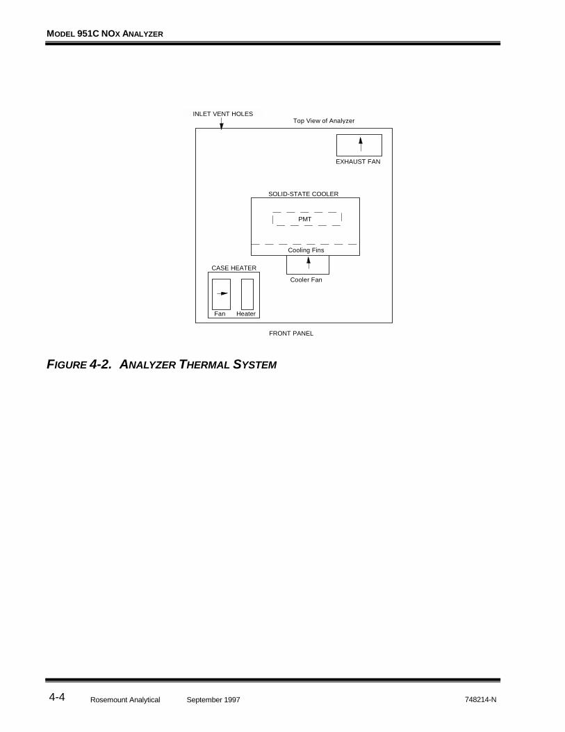
4.4 ANALYZER THERMAL SYSTEM
The Analyzer Thermal System is shown in Figure 4-2. Its basic function is to provide astable thermal environment for the PMT.
The temperature of the PMT must be held within a half-degree band at approximately18°C if it is to produce a useful signal for low concentrations of NOx. This isaccomplished by means of a solid-state cooler which houses the PMT. The heat whichis radiated from the cooler is carried away by the Cooler Fan.
The solid-state cooler must work against a relatively constant load in order to maintainthe temperature of the PMT. This load is produced by a case heater and exhaust fanwhich control the temperature inside the case within a one-degree band(approximately 50°C for ambient temperatures from 4°C to 40°C).
The electronics which support the Analyzer Thermal System and the NO2-to-NOConverter are contained on the Power Supply Board.
FIGURE 4-1. ANALYZER SIGNAL CONDITIONING CIRCUIT
High VoltageSupply
Zero Control
PMTAmplifier
ProgrammableGain
Amplifier
SpanAmplifier
PhotomultiplierTube
Display
Voltage-to-CurrentConverter
PotentiometricOutput
IsolatedCurrentOutput
Power Supply Board
Signal/Control Board
Range Switch Span Control
MODEL 951C NOX ANALYZER
Rosemount Analytical 748214-NSeptember 19974-4
FIGURE 4-2. ANALYZER THERMAL SYSTEM
Fan Heater
CASE HEATER
Cooler Fan
Cooling Fins
PMT
SOLID-STATE COOLER
EXHAUST FAN
Top View of Analyzer
FRONT PANEL
INLET VENT HOLES

5ROUTINE SERVICING
Rosemount Analytical748214-N September 1997 5-1
Servicing requires access to live parts which can cause death or seriousinjury. Refer servicing to qualified personnel.
Ultraviolet light from the ozone generator can cause permanent eyedamage. Do not look directly at the ultraviolet source in ozone generator. Use of ultraviolet filtering glasses is recommended.
Note
The photomultiplier tube must not be exposed to ambient light. If thephotomultiplier tube is exposed to light while the power is on, eitherthrough a loose fitting on the reaction chamber or any other leak, it will bedestroyed. If exposed to ambient light with the power off, the tube will benoisy for some period of time. Unless appropriate precautions areobserved, light can strike the tube upon removal of fittings from thereaction chamber.
5.1 SYSTEM CHECKS AND ADJUSTMENTS
The following procedures may be used to determine the cause of unsatisfactoryinstrument performance, or to make adjustments following replacement ofcomponents. If a recorder is available, use it for convenience and maximum accuracyin the various tests.
5.1.1 DISPLAY FULLSCALE SPAN ADJUSTMENT
If a recorder is used, and has been properly zeroed, it should agree with the displayreading. If not, obtain agreement by adjustment of R20 on the Signal/Control Board(see Figures 3-1, 3-2). If agreement cannot be reached, check the recorder. If therecorder is functioning properly, replace the amplifier board.
WARNING: ELECTRICAL SHOCK HAZARD
WARNING: INTERNAL ULTRAVIOLET LIGHT HAZARD
MODEL 951C NOX ANALYZER
Rosemount Analytical 748214-NSeptember 19975-2
5.1.2 OVERALL SENSITIVITY
Principal factors that determine overall sensitivity of the analyzer are the following: (a)sample flow rate to the reaction chamber, (b) sensitivity of the photomultiplier tube(PMT), and (c) PMT high voltage. If specified fullscale readings are unobtainable byadjustment of the SPAN Control, sensitivity is subnormal. The cause of reducedsensitivity may be in either the flow system (See Section 5.2) or the electronic circuitry(See Section 5.6).
If either the High Voltage Board or the Phototube/Reaction Chamber Assembly hasbeen replaced, a readjustment of the high voltage will probably be required to obtainthe correct overall sensitivity. Adjust R30 on the Power Supply Board (see Figures 3-1,3-3) clockwise to increase (negative) the photomultiplier high voltage and sensitivity,or counterclockwise to decrease (negative) the voltage and sensitivity. Theadjustment range is about -650 V to -2100 V for the regulated DC voltage applied tothe photomultiplier tube. Nominal setting is -1100 volts. However, the voltage shouldbe adjusted as required for overall system sensitivity.
5.1.3 OZONE OUTPUT
To check for adequate output from the ozone lamp, a convenient technique is tocalibrate the analyzer on a high level NO standard such as 250 ppm NO at thenominal 4.0 psi internal sample pressure setpoint, and note the reading. The samplepressure setpoint is then sequentially set to pressures of 3.0, 2.0, and 1.0 psi after astable span gas reading has obtained at the higher pressure setpoint. The span gasvalue will change as the pressure is changed. The difference in span gas valuebetween two successive sample pressure levels should be approximately the same forthe 4.0 to 3.0, 3.0 to 2.0, and 2.0 to 1.0 pressure steps.
If the size of the span gas value difference increases as the sample pressure islowered, the analyzer output is limited by the amount of ozone production from thelamp and the two additional checks should be made. First, verify that the sample flow(not including bypass) does not exceed the nominal 60 to 80 cc/min, at 4.0 psi internalsample pressure. Second, substitute another lamp to see if the ozone output isincreased.
If no other ozone lamp is available, the analyzer sample input pressure may bereduced to the pressure where the ozone limitation is not present. If the lamp output islow and the sample pressure is reduced to restore operation to the condition whereozone limitation is not occurring, some degradation in analyzer response timecharacteristics may occur.
Use extreme caution in troubleshooting the ozone generator. Ozone istoxic.
WARNING: TOXIC GAS HAZARD
ROUTINE SERVICING
Rosemount Analytical748214-N September 1997 5-3
5.1.4 BACKGROUND CURRENT
With zero air supplied to rear panel SAMPLE inlet, excessive background current isevidenced by the inability to obtain zero display reading with adjustment of the ZEROControl. If this cannot be accomplished, the cause must be found and corrected. Thefault may be in either the electronic circuitry or the sample flow system.
First, establish proper performance of the electronic circuitry. Turn on analyzer power.Verify that ZERO Control and amplifier are functioning properly. Then, check forexcessive photomultiplier dark current and/or contamination of the reaction chamberor sample flow system as follows:
5.1.5 EXCESSIVE PHOTOMULTIPLIER DARK CURRENT
To check, shut off all flow to the ozone generator. Turn off ozone generator. Supplycylinder air to rear panel SAMPLE inlet. Note response on display or recorder. If back-ground is still excessive, possible causes are:
• leakage of ambient light to photomultiplier tube
• defective photomultiplier tube
• electrical leakage in socket assembly
CONTAMINATION OF REACTION CHAMBER OR SAMPLE FLOW SYSTEM.See Section 5.4.1.
5.2 SERVICING FLOW SYSTEM
To facilitate servicing and testing, the Model 951C has front drawer access.
Drawing 654090 shows flow system details, including fittings, thread specificationsand connecting tubing.
5.2.1 CLEANING SAMPLE CAPILLARY
If clogging of sample capillary is suspected, measure flow rate as described below.
1. Turn off instrument power and shut off all gases.
2. Refer to Figures 6-1 and 6-3. Cover and shade the fittings on the reaction chamberwith a dark cloth or other light-shielding material. Remove the fitting associatedwith the sample capillary and place a cap over the open fitting to prevent entry ofstray light.

MODEL 951C NOX ANALYZER
Rosemount Analytical 748214-NSeptember 19975-4
Note:
If the opened fitting is inadvertently exposed to ambient light, theinstrument will temporarily give a highly noisy background reading. If so,this condition may be corrected by leaving the instrument on, with highvoltage on, for several hours. If high voltage is on during exposure, thephotomultiplier tube will be destroyed.
3. With instrument power off, supply suitable test gas (dry nitrogen or air) torear-panel SAMPLE inlet.
4. Connect a flowmeter to open end of sample capillary. Adjust internal SAMPLEPressure Regulator to normal operating setting of 4 psig (28 kPa). Verify thatflowmeter indicates appropriate flow of 60 to 80 cc/min.
5. If flow is correct, restore analyzer to normal operation.
6. If flow is low, the capillary requires cleaning or replacement (Proceed with the step5 below).
7. Clean capillary with denatured alcohol, and purge with dry nitrogen or air for oneminute. Reconnect capillary.
8. With the photomultiplier still covered, slowly insert the free end of the capillary intothe corresponding fitting on the reaction chamber. Push the capillary in until ittouches bottom against the internal fitting. Then tighten fitting 1/4 turn past fingertight.
Note:
Do not overtighten capillary internal fitting, as overtightened fittings mayrestrict the sample flow.
5.2.2 OZONE RESTRICTOR FITTING
With instrument power off, supply suitable test gas (dry nitrogen or air) to rear panelAIR inlet. Cover photomultiplier housing with a dark cloth. At the fittings on thereaction chamber, disconnect the ozone tube and place a cap over the open fitting toprevent entry of ambient light. Connect a flowmeter to open end of ozone tube. Adjustthe OZONE Pressure Regulator so that the OZONE Pressure Gauge indicates normaloperating pressure of 20 to 25 psig (138 to 172 kPa). Verify that test flowmeterindicates an appropriate flow of 500 to 600 cc/min for 20 psig.
Subnormal flow indicates clogging in the flow path that supplies air to the ozonegenerator. This path contains a Restrictor (P/N 655519), consisting of a metal fittingwith internal fritted (metal membrane) restrictor to reduce pressure. The fitting isupstream from the inlet port of the ozone generator. If the internal restrictor becomesplugged, the assembly (P/N 655519) must be replaced as it cannot normally becleaned satisfactorily.
ROUTINE SERVICING
Rosemount Analytical748214-N September 1997 5-5
5.3 PHOTOMULTIPLIER TUBE/REACTION CHAMBER
This assembly consists of the photomultiplier tube and socket, the thermoelectriccooler, and the reaction chamber. Refer to Figure 6-1 for location and details ofmounting. Refer to Figure 6-3 for information on the assembly.
The assembly must be removed from the analyzer in order to clean the reactionchamber or to replace the photomultiplier tube.
5.3.1 PHOTOMULTIPLIER TUBE/REACTION CHAMBER REMOVAL
To remove the photomultiplier tube/reaction chamber assembly from the analyzer, dothe follow:
1. Disconnect power from the analyzer.
2. Release pressure from SAMPLE and AIR supplies.
3. Unplug the electrical cable from the Power Supply PC Board.
4. Disconnect the high-voltage cable and the signal cable from the left side of theassembly. Note the two mounting screws just below the connectors.
5. Uncouple the sample and ozone capillaries and the exhaust line from the right sideof the assembly. Note the two mounting screws just below the fittings.
6. Loosen the screws described in steps 4 and 5 above.
7. Lift the assembly from the analyzer.
8. Replace the assembly by reversing the order of steps 1 through 7.
5.3.2 CLEANING REACTION CHAMBER
Note:
Photomultiplier tube will be permanently damaged if exposed to ambientlight while powered with high voltage. Photomultiplier tube will developtemporary electronic noise if exposed to ambient light with high voltageOFF. A temporary noisy condition may be corrected by leaving instrumenton, with high voltage on, for several hours. The required recovery timedepends on intensity and duration of the previous exposure. Noise level onthe most sensitive range usually drops to normal within 24 hours.
If sample gas is properly filtered, the reaction chamber should not require frequentcleaning. In event of carryover or contamination, however, the chamber should bedisassembled to permit cleaning the quartz window and the optical filter. The followingprocedure is recommended.
MODEL 951C NOX ANALYZER
Rosemount Analytical 748214-NSeptember 19975-6
1. Cover and shade the Reaction Chamber/Photomultiplier Assembly with a darkcloth or other light-shielding material.
Note:
Always wear surgical rubber gloves when handling the reaction chamber toprevent contamination from handling.
2. Note the orientation of the fittings. Slowly rotate and withdraw the reactionchamber from the housing. Ensure that no light strikes the photomultiplier tube.
3. Unscrew plastic end cap, thus freeing the quartz window and the red plastic opticalfilter. Note the sequence in which these are assembled.
4. Clean the reaction chamber by the appropriate one of the following two methods,standard or alternate. The standard method is applicable in most cases. Thealternate method is applicable when the instrument has shown high residualfluorescence. That condition is indicated by high residual currents on a zero gasand high differentials between zero gas readings obtained with the ozone lamp onand off.
STANDARD CLEANING PROCEDURE
Using a stiff plastic bristle brush, such as a toothbrush, scrub the Teflon surface andgas ports of the reaction chamber with clean distilled water and Alconox* detergent(P/N 634929). Alconox detergent is included in the shipping kit provided with theModel 951C NOx Analyzer, and is available from Sargent-Welch Scientific Companyunder its catalog number S-195650-A.
Using Alconox and clean, soft facial tissue (NOT industrial wipes), carefully clean thequartz window. Vigorously flush reaction chamber and quartz window with cleandistilled water. Blow out all possible water from internal passages of reaction chamber.Dry reaction chamber and quartz window in a warm oven at 125°F to 150°F (52°C to66°C) for 30 to 45 minutes or purge-dry the parts with dry cylinder air or nitrogen toeliminate all moisture.
Hydrochloric acid (HC1) is a strong acid. It is irritating to the skin, mucousmembranes, eyes and respiratory tract. Direct contact causes severechemical burns.
Avoid Contact with eyes and skin and avoid breathing fumes. Use in hoodor well ventilated place. Wear goggles, rubber gloves and protectiveclothing.
WARNING: ACID HAZARD

ROUTINE SERVICING
Rosemount Analytical748214-N September 1997 5-7
ALTERNATE CLEANING PROCEDURE - FOR HIGH RESIDUAL FLUORESCENCE
Holding the reaction chamber by the tube fittings, and using appropriate caution,immerse the white Teflon part of the chamber in 50% concentrated Reagent Gradehydrochloric acid. After five minutes, rinse thoroughly with de-ionized water, then airdry as in the standard cleaning method above.
Place parts in position and press on end-cap so that mating threads engage properly,without cross threading. Turn mating parts in one continuous motion until the partsmesh. Do not over-torque.
With reaction chamber now assembled, replace and reconnect it in reversed removalsequence. Orient as noted in step 2.
5.3.3 PHOTOMULTIPLIER TUBE AND HOUSING
The photomultiplier tube operates at high DC voltages (nominal setting is -1100 volts)and generates small currents that are highly amplified by the signal-conditioningcircuitry. It is therefore important that ambient humidity and condensed water vapor beexcluded from the interior of the photomultiplier housing. Ambient humidity can resultin electrical leakage, observed as abnormally high dark current. Water vapor orcondensed moisture in contact with the photomultiplier tube may result in anabnormally high noise level during instrument readout on zero air or upscale standardgas.
The Photomultiplier Tube/Reaction Chamber Assembly incorporates several featuresfor exclusion of humidity and moisture. The photomultiplier socket assembly is pottedwith high impedance silicone rubber compound and is sealed from external influenceswith epoxy and rubber gasket material. The socket assembly and the reactionchamber are sealed with O-rings into opposite ends of the tubular photomultiplierhousing. The socket end of the housing may be sealed with either one or two O-rings,depending on the length of the phototube.
5.3.4 REPLACEMENT OF PHOTOMULTIPLIER TUBE
The photomultiplier tube assembly must be removed from the housing in order toreplace the tube. To remove, do the following:
1. Note the orientation of the connectors.
2. Slowly rotate and withdraw the socket assembly from the housing. Note theorientation and placement of the metal shield and the black plastic insulatingcover.
3. Carefully unplug the photomultiplier tube from the socket.
4. Plug a new tube into the socket.
5. Orient the metal shield and black plastic insulator as noted in step 2.
6. Carefully rotate and insert the tube, shield and cover into the housing. Orient asnoted in step 1.

MODEL 951C NOX ANALYZER
Rosemount Analytical 748214-NSeptember 19975-8
5.4 OZONE GENERATION SYSTEM
The ozone generator lamp contains mercury. Lamp breakage could resultin mercury exposure. Mercury is highly toxic if absorbed through skin oringested, or if vapors are inhaled.
Handle lamp assembly with extreme care.
If lamp is broken, avoid skin contact and inhalation in the area of the lampor the mercury spill.
Immediately clean up and dispose of the mercury spill and lamp residue asfollows:
Wearing rubber gloves and goggles, collect all droplets of mercury bymeans of a suction pump and aspirator bottle with long capillary tube. Alternatively, a commercially available mercury spill clean-up kit, such asJ. T. Baker product No. 4439-01, is recommended.
Carefully sweep any remaining mercury and lamp debris into a dust pan. Carefully transfer all mercury, lamp residue and debris into a plastic bottlewhich can be tightly capped. Label and return to hazardous materialreclamation center.
Do not place in trash, incinerate or flush down sewer.
Cover any fine droplets of mercury in non-accessible crevices with calciumpolysulfide and sulfur dust.
This system consists of the ultraviolet lamp, lamp housing, and power supply. Refer toFigure 6-1 for location and details of mounting.
5.4.1 LAMP/HOUSING REMOVAL
To remove the lamp and housing, do the follow:
1. Disconnect power from the instrument.
2. Release pressure from SAMPLE and AIR supplies.
3. Disconnect the air supply tubing from the front of the housing.
4. Disconnect the ozone tube leading to the reaction chamber.
5. Disconnect the power cable from the Power Supply.
6. Uncouple the two Velcro straps which secure the housing to power supply.
7. Lift the housing from the analyzer.
WARNING: TOXIC CHEMICAL HAZARD

ROUTINE SERVICING
Rosemount Analytical748214-N September 1997 5-9
5.4.2 UV LAMP REPLACEMENT
To replace the lamp, do the following:
1. Unscrew and remove end cap.
2. Unscrew aluminum outer lamp housing tube from lamp base, using care not to hitor touch lamp assembly.
Note:
Do not touch lamp. Fingerprints may cause a decrease in lamp output.
1. Replace O-ring in lamp base with new O-ring supplied in kit.
2. Insert replacement lamp assembly using care not to hit or touch lamp housing.
3. Insert new O-ring into new end cap. Screw end cap onto end of lamp housing.
4. Replace the lamp and housing by reversing the steps in this section.
5.4.3 POWER SUPPLY REMOVAL
To remove the Power Supply, do the following:
Refer to Figure 6-1.
1. Remove the lamp and housing as in Section 5.4.2.
2. Disconnect the power lead from the Power Supply Board.
3. Remove the two screws which secure the Power Supply to the bottom plate of theanalyzer.
4. Lift the Power Supply from the analyzer.
5. Replace the Power Supply by reversing the order of the steps in this section.
5.5 CONVERTER ASSEMBLY
To check the heater blanket, verify the continuity of the heater coil.
To check the temperature sensor, refer to Section 3.4 and measure its resistancewhen instrument power is off (should be about 440 ohms) and when instrumentpower is on (should range from 800 to 1,000 ohms). See Table 3-1.
To remove the glass converter tube (see Figure 6-4):
1. Carefully disconnect the blue silicon connectors from the ends of the inlet andoutlet tubes.

MODEL 951C NOX ANALYZER
Rosemount Analytical 748214-NSeptember 19975-10
The inlet tube is partially filled with glass wool and has a larger inside diameterthan the outlet tube. Further, the outlet tube and the sample capillary (P/N615989) connect to the same stainless steel tee.
2. Release the assembly and disconnect the heater and sensor connectors from thetemperature control board.
3. Remove the lacing from the heater blanket, and remove the converter tube. Notethe position of the temperature sensor and its leads as the aluminum foil isunwrapped.
4. Replace the defective part and reassemble. The temperature sensor shouldcontact the converter tube with the top of the sensor at the midpoint of theconverter. Route sensor leads axially to the outer end.
5. Condition the converter as described in Sections 3.4 and 3.5.
5.6 SERVICING ELECTRONIC CIRCUITRY
For troubleshooting the electronic system, refer to Section 4 and the appropriatepictorial diagrams at the back of the manual. The electronic system utilizes printedcircuit boards with solid-state components. After a malfunction is traced to a particularboard, the recommended procedure is to return it to the factory for repair.

6REPLACEMENT PARTS
Rosemount Analytical748214-N September 1997 6-1
The following parts are recommended for routine maintenance and troubleshooting ofthe Model 951C NOx Analyzer. If the troubleshooting procedures do not resolve theproblem, contact your local Rosemount Analytical service office. A list of RosemountAnalytical Service Centers is located in the back of this manual. Figures 6-1 through 6-5 show locations of components and assemblies.
Tampering or unauthorized substitution of components may adverselyaffect safety of this product. Use only factory documented components forrepair.
6.1 CIRCUIT BOARD REPLACEMENT POLICY
In most situations involving a malfunction of a circuit board, it is more practical toreplace the board than to attempt isolation and replacement of the individualcomponent. The cost of test and replacement will exceed the cost of a rebuiltassembly from the factory.
The following list does not include individual electronic components. If circumstancesnecessitate replacement of an individual component which can be identified byinspection or from the schematic diagrams, obtain the replacement component from alocal source of supply.
6.2 REPLACEMENT PARTSCOMMON PARTS
Refer to Figure 6-1.
655519 Air Restrictor Fitting657091 Capacitor Assembly655166 Capillary, Bypass655589 Capillary, Sample Hi623719 Capillary, Sample Lo654068 Temperature Control Assembly654070 Converter Assembly
WARNING: PARTS INTEGRITY

MODEL 951C NOX ANALYZER
Rosemount Analytical 748214-NSeptember 19976-2
655303 Exhaust Fan654052 Fan Assembly898587 Fuse 3.15 A902413 Fuse 6.25 A654390 I/O Assembly652173 Ozone Generator658156 Ozone Generator UV Lamp Replacement Kit655129 Ozone Generator Power Supply654062 Photomultiplier Assembly655332 Power Supply Assembly654085 Pressure Switch623936 Sample Flow Restrictor644055 Sample Pressure Gauge815187 Sample Regulator *622917 Sensor, Temperature654050 Signal Board654878 Transformer/Inductor Assembly
PHOTOMULTIPLIER ASSEMBLY 654062Refer to Figure 6-2.
654943 Housing649541 Insulating Washer636318 Magnetic Shield630916 Magnetic Shield001522 O-Ring008423 O-Ring, Photomultiplier655168 Photomultiplier Tube654381 Reaction Chamber654086 Socket Assembly639722 Thermal Shield
CONVERTER ASSEMBLY 654070Refer to Figure 6-3.
632784 Connector, Blue Silicone657127 Heater632782 Temperature Sensor632795 Tube
TEMPERATURE CONTROL ASSEMBLY 654068Refer to Figure 6-4.

REPLACEMENT PARTS
Rosemount Analytical748214-N September 1997 6-3
622733 Fan622732 Heater655335 Temperature Control Board900492 Thermal Fuse
FIGURE 6-1. MAJOR ASSEMBLIES OF THE MODEL 951C
Sample Regulator815187 Sample Pressure Gauge
644055
I/O Assembly654390
Sample Flow Restrictor623936
Air Restrictor655519 (on Ozone Generator inlet)
Transformer/Inductor Assembly654878
Fan Assembly654052
Pressure Switch654085
Case Heater TemperatureControl Assembly 654068(See Figure 6-4)
Converter Assembly654070 (See Figure 6-3)
Photomultiplier Assembly654062 (See Figure 6-2)
Ozone Generator Power Supply655129
Ozone Generator 658156UV Lamp Replacement Kit 658156
Exhaust Fan655303
Power Supply Assembly655332
Sensor622917

MODEL 951C NOX ANALYZER
Rosemount Analytical 748214-NSeptember 19976-4
FIGURE 6-2. PHOTOMULTIPLIER HOUSING ASSEMBLY
Thermocooler Housing654943
Socket Assembly654086
Magnetic Shield636318
Reaction Chamber 654381
O-Ring 008423
Thermal Shield 639722
Insulating Washer 649541
Magnetic Shield630916
PVC Tube
O-Rings 001522
Photomultiplier Tube and MagneticShield (PN 630916) to be Flush
Photomultiplier Tube655168
.3 PVC Tube
Photomultiplier Tube
Magnetic Shield630916
Note: Silicone lubricant to be applied to o-rings.

REPLACEMENT PARTS
Rosemount Analytical748214-N September 1997 6-5
FIGURE 6-3. CONVERTER ASSEMBLY
Heater657127
Temperature Sensor632782
Converter Tube - Packed632795
Connectors, GlassTube632784
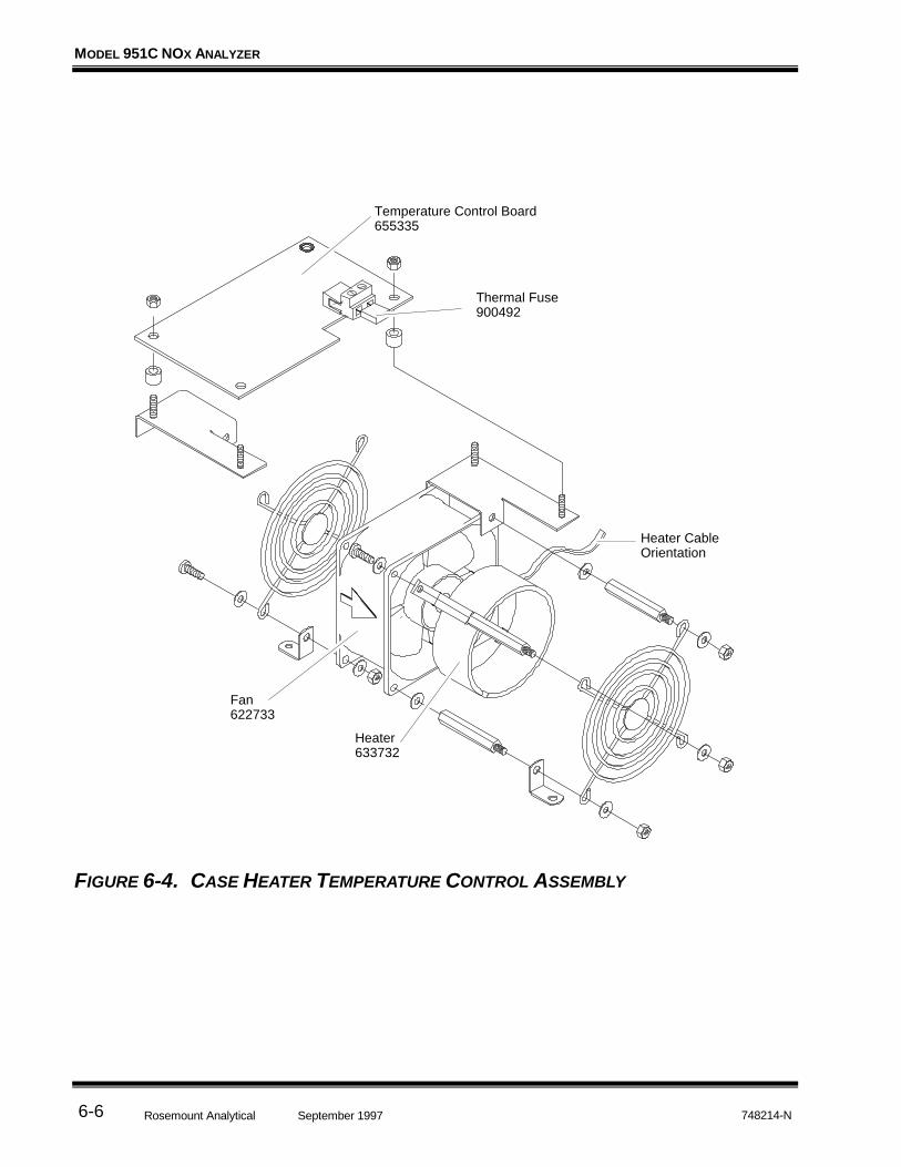
MODEL 951C NOX ANALYZER
Rosemount Analytical 748214-NSeptember 19976-6
FIGURE 6-4. CASE HEATER TEMPERATURE CONTROL ASSEMBLY
Heater633732
Heater CableOrientation
Fan622733
Temperature Control Board655335
Thermal Fuse900492
Edited from selected paragraphs of the CompressedGas Association's "Handbook of Compressed Gases"published in 1981Compressed Gas Association1235 Jefferson Davis HighwayArlington, Virginia 22202Used by Permission
1. Never drop cylinders or permit them to strike each other violently.
2. Cylinders may be stored in the open, but in such cases, should be protected againstextremes of weather and, to prevent rusting, from the dampness of the ground. Cylindersshould be stored in the shade when located in areas where extreme temperatures areprevalent.
3. The valve protection cap should be left on each cylinder until it has been securedagainst a wall or bench, or placed in a cylinder stand, and is ready to be used.
4. Avoid dragging, rolling, or sliding cylinders, even for a short distance; they should bemoved by using a suitable hand-truck.
5. Never tamper with safety devices in valves or cylinders.
6. Do not store full and empty cylinders together. Serious suckback can occur when anempty cylinder is attached to a pressurized system.
7. No part of cylinder should be subjected to a temperature higher than 125°F (52°C). Aflame should never be permitted to come in contact with any part of a compressed gascylinder.
8. Do not place cylinders where they may become part of an electric circuit. When electricarc welding, precautions must be taken to prevent striking an arc against the cylinder.
Rosemount Analytical Inc.4125 EAST LA PALMA AVENUE • ANAHEIM, CALIFORNIA 92807-1802 • 714-986-7600 • FAX 714-577-8006
JULY 1997 • 748525-C • PRINTED IN USA
GENERAL PRECAUTIONS FOR HANDLING AND
STORING HIGH PRESSURE GAS CYLINDERS

(blank)

Goods and part(s) (excluding consumables) manufactured by Seller are warranted to be free fromdefects in workmanship and material under normal use and service for a period of twelve (12)months from the date of shipment by Seller. Consumables, glass electrodes, membranes, liquidjunctions, electrolyte, o-rings, etc., are warranted to be free from defects in workmanship andmaterial under normal use and service for a period of ninety (90) days from date of shipment bySeller. Goods, part(s) and consumables proven by Seller to be defective in workmanship and/ormaterial shall be replaced or repaired, free of charge, F.O.B. Seller's factory provided that the goods,part(s) or consumables are returned to Seller's designated factory, transportation charges prepaid,within the twelve (12) month period of warranty in the case of goods and part(s), and in the case ofconsumables, within the ninety (90) day period of warranty. This warranty shall be in effect forreplacement or repaired goods, part(s) and the remaining portion of the ninety (90) day warranty inthe case of consumables. A defect in goods, part(s) and consumables of the commercial unit shallnot operate to condemn such commercial unit when such goods, part(s) and consumables arecapable of being renewed, repaired or replaced.
The Seller shall not be liable to the Buyer, or to any other person, for the loss or damage directly orindirectly, arising from the use of the equipment or goods, from breach of any warranty, or from anyother cause. All other warranties, expressed or implied are hereby excluded.
IN CONSIDERATION OF THE HEREIN STATED PURCHASE PRICE OF THE GOODS, SELLERGRANTS ONLY THE ABOVE STATED EXPRESS WARRANTY. NO OTHER WARRANTIES AREGRANTED INCLUDING, BUT NOT LIMITED TO, EXPRESS AND IMPLIED WARRANTIES ORMERCHANTABILITY AND FITNESS FOR A PARTICULAR PURPOSE.
Limitations of Remedy. SELLER SHALL NOT BE LIABLE FOR DAMAGES CAUSED BY DELAY INPERFORMANCE. THE SOLE AND EXCLUSIVE REMEDY FOR BREACH OF WARRANTY SHALLBE LIMITED TO REPAIR OR REPLACEMENT UNDER THE STANDARD WARRANTY CLAUSE. INNO CASE, REGARDLESS OF THE FORM OF THE CAUSE OF ACTION, SHALL SELLER'SLIABILITY EXCEED THE PRICE TO BUYER OF THE SPECIFIC GOODS MANUFACTURED BYSELLER GIVING RISE TO THE CAUSE OF ACTION. BUYER AGREES THAT IN NO EVENTSHALL SELLER'S LIABILITY EXTEND TO INCLUDE INCIDENTAL OR CONSEQUENTIALDAMAGES. CONSEQUENTIAL DAMAGES SHALL INCLUDE, BUT ARE NOT LIMITED TO, LOSSOF ANTICIPATED PROFITS, LOSS OF USE, LOSS OF REVENUE, COST OF CAPITAL ANDDAMAGE OR LOSS OF OTHER PROPERTY OR EQUIPMENT. IN NO EVENT SHALL SELLER BEOBLIGATED TO INDEMNIFY BUYER IN ANY MANNER NOR SHALL SELLER BE LIABLE FORPROPERTY DAMAGE AND/OR THIRD PARTY CLAIMS COVERED BY UMBRELLA INSURANCEAND/OR INDEMNITY COVERAGE PROVIDED TO BUYER, ITS ASSIGNS, AND EACHSUCCESSOR INTEREST TO THE GOODS PROVIDED HEREUNDER.
Force Majeure. Seller shall not be liable for failure to perform due to labor strikes or acts beyondSeller's direct control.
Rosemount Analytical
Rosemount Analytical Inc.4125 EAST LA PALMA AVENUE • ANAHEIM, CALIFORNIA 92807-1802 • 714-986-7600 • FAX 714-577-8006
FEBRUARY 1997 • 7485189-C • PRINTED IN USA
WARRANTY

(blank)
Field service and repair facilities are located worldwide.
U.S.A.To obtain field service on-site or assistance with a service problem, contact (24 hours, 7days a week):
National Response Center1-800-654-7768
INTERNATIONALContact your local Rosemount Sales and Service office for service support.
FACTORYFor order administration, replacement Parts, application assistance, on-site or factory repair,service or maintenance contract information, contact:
Rosemount Analytical Inc.Process Analytical DivisionCustomer Service Center
1-800-433-6076
RETURNING PARTS TO THE FACTORYBefore returning parts, contact the Customer Service Center and request a ReturnedMaterials Authorization (RMA) number. Please have the following information when you call:Model Number, Serial Number, and Purchase Order Number or Sales Order Number.
Prior authorization by the factory must be obtained before returned materials will beaccepted. Unauthorized returns will be returned to the sender, freight collect.
When returning any product or component that has been exposed to a toxic, corrosive orother hazardous material or used in such a hazardous environment, the user must attach anappropriate Material Safety Data Sheet (M.S.D.S.) or a written certification that the materialhas been decontaminated, disinfected and/or detoxified.
Return to:Rosemount Analytical Inc.
4125 East La Palma AvenueAnaheim, California 92807-1802
Rosemount Analytical Inc.4125 EAST LA PALMA AVENUE • ANAHEIM, CALIFORNIA 92807-1802 • 714-986-7600 • FAX 714-577-8006
JULY 1997 • 748190-G • PRINTED IN USA
FIELD SERVICE AND REPAIR FACILITIES

(blank)


