Rosemount 2120 Vibrating Fork Liquid Level Switch 2008 Rosemount 2120 † Function virtually...
20
Product Data Sheet 00813-0100-4030, Rev DB February 2008 Rosemount 2120 www.rosemount.com • Function virtually unaffected by flow, bubbles, turbulence, foam, vibration, solids content, coating, properties of the liquid, and product variations • No need for calibration and requires minimum installation procedures • Easy terminal access, polarity insensitive and short circuit protection • No moving parts or crevices means virtually no maintenance • Electronic, self-checking and condition monitoring - Heartbeat LED gives status and health information • Adjustable Switching Delay for turbulent/splashing applications • Magnetic test point makes functional test easy • Small in size and weight • “Fast Drip” Fork Design gives quicker response time especially with viscous liquids • Explosion/Flameproof and Intrinsically Safe options • SIL 2 of IEC 61508 • DIBt/WHG overfill protection COMING SOON Rosemount 2130 High Temperature Vibrating Fork Level Switch • Enhanced diagnostics features improved self-checking and fault monitoring • DPDT/DPCO relay output cassette • 8...16 mA output cassette • AS-i Bus output cassette Consult factory for availability. Contents Measurement Principle . . . . . . . . . . . . . . . . . . . . . . . . . . . . . . . . . . . . . . . . . . . . . . . . page -2 Special Features . . . . . . . . . . . . . . . . . . . . . . . . . . . . . . . . . . . . . . . . . . . . . . . . . . . . . page -2 Rosemount 2120 Application Examples . . . . . . . . . . . . . . . . . . . . . . . . . . . . . . . . . . . page -3 Select Rosemount 2120 Vibrating Fork Liquid Level Switch . . . . . . . . . . . . . . . . . . . page -4 Application and Installation Best Practices . . . . . . . . . . . . . . . . . . . . . . . . . . . . . . . . . page -5 Specifications . . . . . . . . . . . . . . . . . . . . . . . . . . . . . . . . . . . . . . . . . . . . . . . . . . . . . . . page -6 Product Certifications . . . . . . . . . . . . . . . . . . . . . . . . . . . . . . . . . . . . . . . . . . . . . . . . . page -8 Dimensional Drawings . . . . . . . . . . . . . . . . . . . . . . . . . . . . . . . . . . . . . . . . . . . . . . . page -10 Ordering Information . . . . . . . . . . . . . . . . . . . . . . . . . . . . . . . . . . . . . . . . . . . . . . . . . page -13 Rosemount 2120 Vibrating Fork Liquid Level Switch
Transcript of Rosemount 2120 Vibrating Fork Liquid Level Switch 2008 Rosemount 2120 † Function virtually...
Product Data Sheet00813-0100-4030, Rev DB
February 2008 Rosemount 2120
Rosemount 2120 Vibrating
Fork Liquid Level Switch
• Function virtually unaffected by flow, bubbles,
turbulence, foam, vibration, solids content,
coating, properties of the liquid, and product
variations
• No need for calibration and requires minimum
installation procedures
• Easy terminal access, polarity insensitive and
short circuit protection
• No moving parts or crevices means virtually
no maintenance
• Electronic, self-checking and condition
monitoring - Heartbeat LED gives status and
health information
• Adjustable Switching Delay for
turbulent/splashing applications
• Magnetic test point makes functional test easy
• Small in size and weight
• “Fast Drip” Fork Design gives quicker
response time especially with viscous liquids
• Explosion/Flameproof and Intrinsically
Safe options
• SIL 2 of IEC 61508
• DIBt/WHG overfill protection
COMING SOON
Rosemount 2130 High Temperature
Vibrating Fork Level Switch
• Enhanced diagnostics features improved self-checking and
fault monitoring
• DPDT/DPCO relay output cassette
• 8...16 mA output cassette
• AS-i Bus output cassette
Consult factory for availability.
www.ros
Contents
Measurement Principle . . . . . . . . . . . . . . . . . . . . . . . . . . . . . . . . . . . . . . . . . . . . . . . . page -2
Special Features. . . . . . . . . . . . . . . . . . . . . . . . . . . . . . . . . . . . . . . . . . . . . . . . . . . . . page -2
Rosemount 2120 Application Examples . . . . . . . . . . . . . . . . . . . . . . . . . . . . . . . . . . . page -3
Select Rosemount 2120 Vibrating Fork Liquid Level Switch . . . . . . . . . . . . . . . . . . . page -4
Application and Installation Best Practices . . . . . . . . . . . . . . . . . . . . . . . . . . . . . . . . . page -5
Specifications . . . . . . . . . . . . . . . . . . . . . . . . . . . . . . . . . . . . . . . . . . . . . . . . . . . . . . . page -6
Product Certifications . . . . . . . . . . . . . . . . . . . . . . . . . . . . . . . . . . . . . . . . . . . . . . . . . page -8
Dimensional Drawings . . . . . . . . . . . . . . . . . . . . . . . . . . . . . . . . . . . . . . . . . . . . . . . page -10
Ordering Information. . . . . . . . . . . . . . . . . . . . . . . . . . . . . . . . . . . . . . . . . . . . . . . . . page -13
emount.com
Product Data Sheet00813-0100-4030, Rev DB
February 2008Rosemount 2120
Superior Reliability in a Universal Package
The Rosemount 2120 is a liquid point level switch
based on the vibrating short fork technology making
it suitable for virtually all liquid applications. Complete
range of process connections, wide choice of
housing and wetted parts materials, four different
switching functions, extended fork lengths,
hazardous area and overfill approvals make it
configurable to almost all requirements.
MEASUREMENT PRINCIPLE
The Rosemount 2120 is a liquid point level switch
designed using the principle of a tuning fork. A
piezo-electric crystal is used to oscillate the forks at
their natural frequency. Changes to this frequency
are continuously monitored. When the 2120 is used
as a low alarm, the liquid in the vessel drains down
past the fork, resulting in a change of natural
frequency; this is detected by the electronics which
switch the output state. When used as a high alarm,
the liquid rises in the vessel, makes contact with the
fork and again the output switches.
Short Fork Technology
The natural frequency (~1300Hz) of the fork has
been chosen to avoid interference from plant
vibration which may cause false switching. This
allows for minimum intrusion into the vessel or pipe
through the use of a short fork. Using Short Fork
Technology, the Rosemount 2120 is designed for use
in virtually all liquid applications. Extensive research
has maximized the operational effectiveness of the
fork design making it suitable for almost all liquids,
including coating liquids (avoid bridging of forks),
aerated liquids, and slurries.
SPECIAL FEATURES
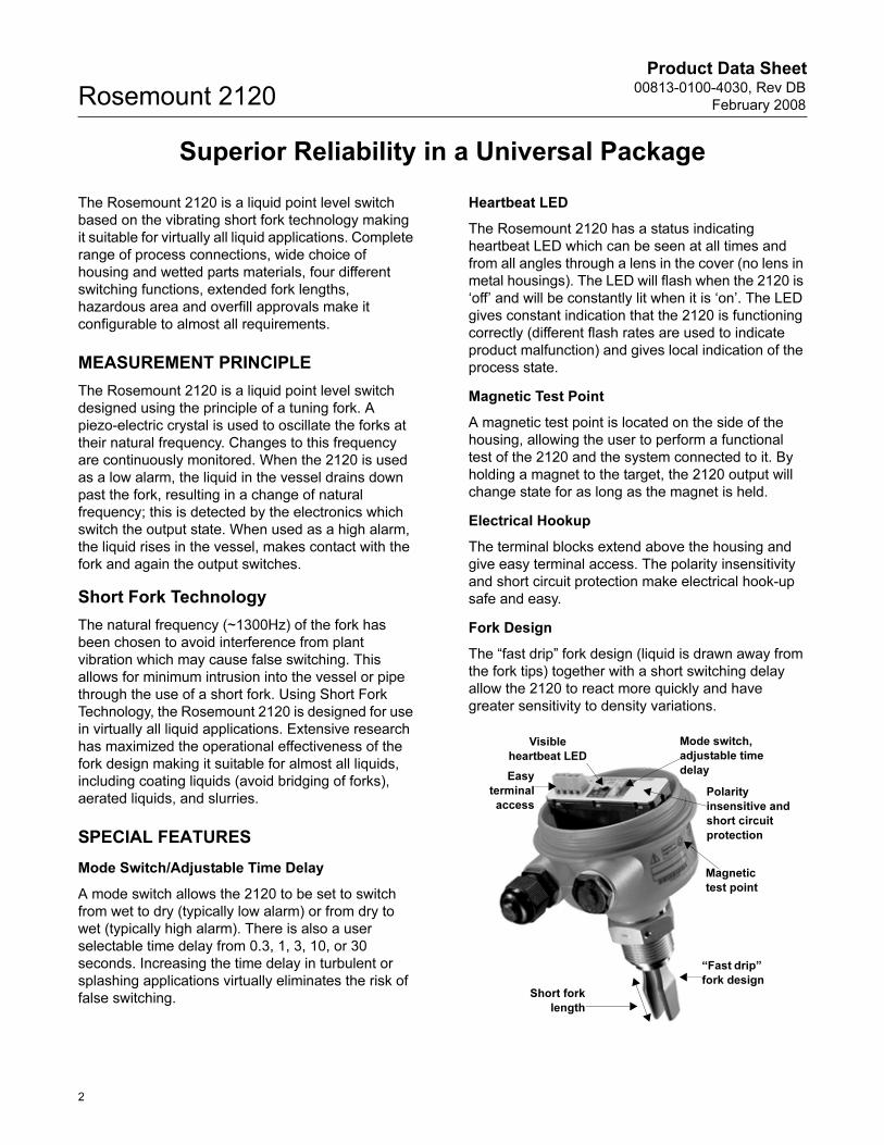
Mode Switch/Adjustable Time Delay
A mode switch allows the 2120 to be set to switch
from wet to dry (typically low alarm) or from dry to
wet (typically high alarm). There is also a user
selectable time delay from 0.3, 1, 3, 10, or 30
seconds. Increasing the time delay in turbulent or
splashing applications virtually eliminates the risk of
false switching.
Heartbeat LED
The Rosemount 2120 has a status indicating
heartbeat LED which can be seen at all times and
from all angles through a lens in the cover (no lens in
metal housings). The LED will flash when the 2120 is
‘off’ and will be constantly lit when it is ‘on’. The LED
gives constant indication that the 2120 is functioning
correctly (different flash rates are used to indicate
product malfunction) and gives local indication of the
process state.
Magnetic Test Point
A magnetic test point is located on the side of the
housing, allowing the user to perform a functional
test of the 2120 and the system connected to it. By
holding a magnet to the target, the 2120 output will
change state for as long as the magnet is held.
Electrical Hookup
The terminal blocks extend above the housing and
give easy terminal access. The polarity insensitivity
and short circuit protection make electrical hook-up
safe and easy.
Fork Design
The “fast drip” fork design (liquid is drawn away from
the fork tips) together with a short switching delay
allow the 2120 to react more quickly and have
greater sensitivity to density variations.
Easy
terminal
access
Magnetic
test point
“Fast drip”
fork designShort fork
length
Mode switch,
adjustable time
delay
Visible
heartbeat LED
Polarity
insensitive and
short circuit
protection
2
Product Data Sheet00813-0100-4030, Rev DB
February 2008 Rosemount 2120
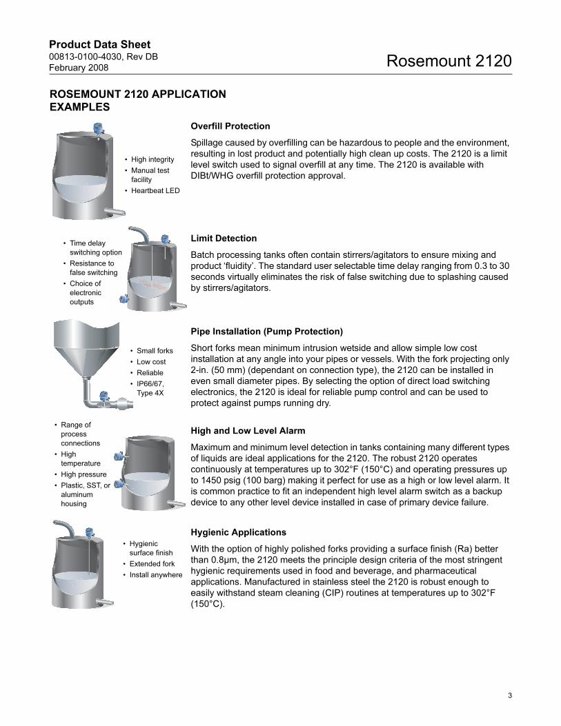
ROSEMOUNT 2120 APPLICATION EXAMPLES
Overfill Protection
Spillage caused by overfilling can be hazardous to people and the environment,
resulting in lost product and potentially high clean up costs. The 2120 is a limit
level switch used to signal overfill at any time. The 2120 is available with
DIBt/WHG overfill protection approval.
Limit Detection
Batch processing tanks often contain stirrers/agitators to ensure mixing and
product ‘fluidity’. The standard user selectable time delay ranging from 0.3 to 30
seconds virtually eliminates the risk of false switching due to splashing caused
by stirrers/agitators.
Pipe Installation (Pump Protection)
Short forks mean minimum intrusion wetside and allow simple low cost
installation at any angle into your pipes or vessels. With the fork projecting only
2-in. (50 mm) (dependant on connection type), the 2120 can be installed in
even small diameter pipes. By selecting the option of direct load switching
electronics, the 2120 is ideal for reliable pump control and can be used to
protect against pumps running dry.
High and Low Level Alarm
Maximum and minimum level detection in tanks containing many different types
of liquids are ideal applications for the 2120. The robust 2120 operates
continuously at temperatures up to 302°F (150°C) and operating pressures up
to 1450 psig (100 barg) making it perfect for use as a high or low level alarm. It
is common practice to fit an independent high level alarm switch as a backup
device to any other level device installed in case of primary device failure.
Hygienic Applications
With the option of highly polished forks providing a surface finish (Ra) better
than 0.8µm, the 2120 meets the principle design criteria of the most stringent
hygienic requirements used in food and beverage, and pharmaceutical
applications. Manufactured in stainless steel the 2120 is robust enough to
easily withstand steam cleaning (CIP) routines at temperatures up to 302°F
(150°C).
2120 Vibrating Fork Level Switch
www.rosemount.com
• High integrity
• Manual test
facility
• Heartbeat LED
2120 Vibrating Fork Level Switch
www.rosemount.com
2120 Vibrating Fo
rk Level Switch
www.ro
semount.co
m
• Time delay
switching option
• Resistance to
false switching
• Choice of
electronic
outputs
2120 Vibrating Fork Level Switch
www.rosemount.com
• Small forks
• Low cost
• Reliable
• IP66/67,
Type 4X
2120 Vibratin
g Fo
rk Level Switch
www.ro
semount.co
m
2120 Vibratin
g Fo
rk Level Switch
www.ro
semount.co
m
• Range of
process
connections
• High
temperature
• High pressure
• Plastic, SST, or
aluminum
housing
2120 Vibrating Fork Level Switch
www.rosemount.com
• Hygienic
surface finish
• Extended fork
• Install anywhere
3
Product Data Sheet00813-0100-4030, Rev DB
February 2008Rosemount 2120
SELECT ROSEMOUNT 2120 VIBRATING FORK LIQUID LEVEL SWITCH
The Rosemount 2120 switch consists of housing,
tank connection, and forks. The tank connection and
forks are the only wetted parts.
Switch Housing
The switch housing is available in glass filled nylon,
aluminum or SST with two M20, 1/2-in., or 3/4-in. NPT
cable/conduit entries. It can be ordered with
Intrinsically Safe or Explosion Proof / Flame Proof
approvals. Approval depends on the housing type,
see Product Certifications on page 14.
Electronics
Standard two core cable can be used with any power
supply from 20 to 264V ac (50/60 Hz) or 20 to 60V dc
to connect the 2120 in series with a load to achieve
direct load switching. The output acts as a simple
SPST switch that changes state with liquid presence.
Alternatively the switching function of the SPCO
relay electronics output can be used. The 2120 also
has the option of electronics that can be interfaced
directly to a PLC using the PNP transistor output
model (three-wire). The Intrinsically Safe (IS) 2120 to
ATEX EEx ia approval interfaces directly with
standard NAMUR (DIN 19234, IEC60947-5-6,
EN50227) isolation amplifiers.
Tank Connection and Fork
Fork Length
Short fork for minimum intrusion installation
(minimum 2-in. [50 mm]) or fork extensions up to
118-in. (3m) are available. See “Dimensional
Drawings” on page 10.
Threaded Connection
Threads: R 3/4-in. and 1-in. (BSPT); G 3/4-in. and
1-in. (BSPP); 3/4-in. and 1-in. NPT
Material: 316L SST, Hastelloy C
Accessories: A stainless steel adjustable clamp
gland is available for use with extended length
2120 (1-in. models only). This is threaded 11/2-in.
BSPP for connection to the vessel, and allows the
1-in. extended length 2120 to be raised or
lowered as desired then clamped in position. See
Spare Parts and Accessories on page 16.
Flanged Connections
Flange: ANSI B16.5 (1.5-in. or larger), BS4504
(DN40 or larger)
Material: 316L SST, Halar/PFA coated,
other on request
Hygienic Connections
Fittings: 1.5-in. (38 mm) or 2-in. (51 mm)
Tri-Clamp, 1-in. BSPP (G) O-ring seal, or other on
request
Material: 316L SST
Options: Hand polished wetside to a finish better
than 0.8µm meets the principle design criteria of
the most stringent hygienic requirements.
Accessories: A mounting kit comprising vessel
fitting, Nitrile seal and clamp ring is available for
use with 2-in. (51 mm) Tri-Clamp 2120. A fitting
boss with Fluorocarbon (FPM/FKM) O-ring is
available for use with O-ring seal 2120. See
Spare Parts and Accessories on page 16.
Wetted material in SST,
Hastelloy or Halar/PFA coating
IP66/67 or Type 4X
housings in
plastic, aluminum
or 316 SST
Two cable/
conduit
entries
Short fork length or
extensions up to
118-in. (3 m)
Threaded, Flanged, or
Hygienic Connections
Direct Load,
Relay,
PLC/PNP, or IS
NAMUR
electronics
1.5-in. (38 mm)
or 2-in. (51 mm)
Tri-Clamp
4
Product Data Sheet00813-0100-4030, Rev DB
February 2008 Rosemount 2120
APPLICATION AND INSTALLATION BEST PRACTICES
Application Considerations:
• Ensure liquid is inside the temperature and pressure ranges (see specifications).
• Check that the liquid is inside recommended viscosity range 0.2 to 10,000 cP.
• Examples of products that are too viscous are chocolate syrup, ketchup, peanut butter and bitumen.
• The switch will still detect products above 10,000 cP, however, the drain times become prohibitively long or cleaning may become necessary to resume dry functioning.
• Check that the liquid density is above 37.5 lb/ft3 (600 kg/m3).
• Examples of products with densities too low are propane and propylene.
• Check for risk of build-up on the forks.
• Avoid situations where drying and coating products may create excessive build-up.
• Ensure there is no risk of bridging the forks.
• If coating or bridging may occur, ensure the Halar/PFA coated version is used to reduce the risk of build-up.
• Examples of products that can create bridging of forks are dense paper slurries and bitumen.
• Check the solids content in the liquid.
• Problems may occur if product coats and dries causing caking.
• As a guideline maximum solid particle diameter in the liquid is 0.2-in. (5 mm).
• Extra consideration is needed when dealing with particles bigger than 0.2-in. (5 mm), consult factory.
• Foam
• In almost all cases the 2120 is insensitive to foams (does not see the foam).
• However in rare occasions some very dense foams may be seen as liquid, known example of this is found in ice-cream and orange juice manufacturing.
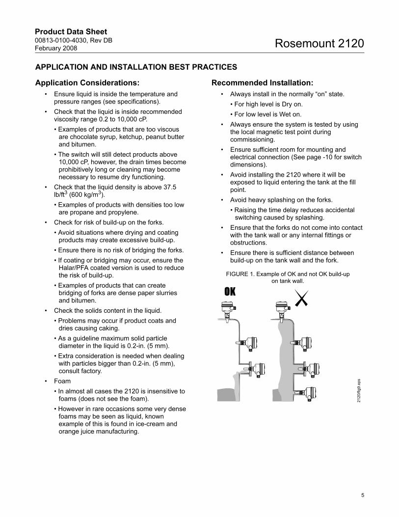
Recommended Installation:
• Always install in the normally “on” state.
• For high level is Dry on.
• For low level is Wet on.
• Always ensure the system is tested by using the local magnetic test point during commissioning.
• Ensure sufficient room for mounting and electrical connection (See page -10 for switch dimensions).
• Avoid installing the 2120 where it will be exposed to liquid entering the tank at the fill point.
• Avoid heavy splashing on the forks.
• Raising the time delay reduces accidental switching caused by splashing.
• Ensure that the forks do not come into contact with the tank wall or any internal fittings or obstructions.
• Ensure there is sufficient distance between build-up on the tank wall and the fork.
FIGURE 1. Example of OK and not OK build-up on tank wall.
2120/fig9.eps
5
Product Data Sheet00813-0100-4030, Rev DB
February 2008Rosemount 2120
Specifications
Physical
ProductRosemount 2120 Vibrating Fork Liquid Level Switch
Measuring principleVibrating Fork
ApplicationsMost liquids including coating liquids, aerated liquids, and slurries
Mechanical
Housing/Enclosure
ConnectionsSee Process Connection Size / Type on page 13.
Extended LengthsAvailable as standard to a maximum of 118-in. (3000 mm),
other on request
Process Material316L Stainless Steel (1.4404), Hastelloy C or Halar (ECTFE) / PFA
co-polymer coating (39.37-in. [1000 mm] max). Hand polished to
better than 0.8µm option available for hygienic connections.
Gasket material for 3/4 in. and 1 in. BSPP (G) is Non-asbestos
BS7531 Grade X carbon fiber with rubber binder.
Dimensional DrawingsSee “Dimensional Drawings” on page 10
Performance
Hysteresis (water)±0.039-in. (± 1mm) nom.
Switching Point (water)0.5-in. (13 mm) from tip (vertical) / from edge (horizontal) of fork
(this will vary with different liquid densities).
Functional
Maximum Operating PressureFinal rating depends on tank connection
Threaded Connection
See Figure 2.
Note: Clamp gland (02120-2000-0001), see page -16, limits
the maximum operating pressure to 18.85 psig (1.3 barg).
Hygienic Connection
435 psig (30 barg)
Flanged Connection
See Figure 2 and Table 1 (whichever one is lower).
FIGURE 2. Process Pressure
Housing Code A D X Y S T
Housing
material
Nylon PA66
30%GF
Al alloy ASTM
B26 356-T6 or
LM25 TF
316C12
Stainless
Steel
LED Window PMMA none none
Conduit Entry M20 1/2-in.
NPT
M20 3/4-in.
NPT
M20 3/4-in.
NPT
Ingress
Protection
IP66/67 to
EN60529
IP66/67 to
EN60529,
Type 4X
IP66/67 to
EN60529,
Type 4X
TABLE 1. Maximum Flange Pressure Rating
Standard Class/Rating SST Flanges
ANSI 150 lb. 275 psig(1)
(1) At 100°F (38°C), the rating decreases with increasing temp.
ANSI 300 lb. 720 psig(1)
ANSI 600 lb. 1,440 psig(1)
DIN PN 10/16 10/16 barg(2)
DIN PN 25/40 25/40 barg(2)
DIN PN 64 64 barg(2)
(2) At 248°F (120°C), the rating decreases with increasing temp.
DIN PN 100 100 barg(2)
1450 (100)
1160 (80)
-14.5 (-1.0)
-40
(-40)
122
(50)
302
(150)
Process Temperature °F (°C)Pro
ce
ss
Pre
ss
ure
ps
ig (
ba
rg)
2120/2
120_18A
B.E
PS
32 (0)
32
(0)
6
Product Data Sheet00813-0100-4030, Rev DB
February 2008 Rosemount 2120
TemperatureSee Figure 3.
FIGURE 3. Temperature
Liquid Density RangeMinimum 37.5 lb/ft3 (600 kg/m3)
Liquid Viscosity Range0.2 to 10,000 cP (centiPose)
Solids Content and CoatingMaximum recommended diameter of solid particles in the liquid is
0.2-in. (5 mm).
For coating product, avoid bridging of forks.
Switching DelayUser selectable 0.3, 1, 3, 10, 30 seconds delay dry to
wet/wet to dry
CIP (Clean In Place) CleaningWithstands steam cleaning routines up to 302°F (150°C)
Electrical
Switching ModeUser selectable (Dry = on or Wet = on)
ProtectionPolarity insensitive. Over-current, short-circuit and load-missing
protection. Surge protection to IEC61326.
Terminal Connection (wire diameter)Max. 0.1-in2 (2.5 mm2) (Note national regulations)
Conduit Plugs/Cable Gland• Metal Ex d Housing: Conduit entries for explosion proof areas
are shipped with two brass conduit plugs.
• Plastic housing with direct load, PNP/PLC and IS electronics
are shipped with one PA66(1) cable gland and one blanking
plug.
• Plastic housing with relay electronics are shipped with two
PA66(1) cable glands.
GroundingThe 2120 should always be grounded either through the terminals
or using the external ground connection provided.
Electrical Connections• Direct load switching (two-wire)
• Solid state PNP output for direct interface to PLC’s (three wire)
• SPCO single relay for voltage free contacts
• Intrinsically Safe (IS) NAMUR to DIN 19234, IEC 60947-5-6
(1) Cable diameter 0.2 to 0.3-in. (5 to 8 mm)
176 (80)
140
(60)
-40 (-40)
-40
(-40)
302
(150)
Process Temperature °F (°C)
Am
bie
nt
Te
mp
era
ture
°F
(°C
)
2120/2
120_18A
C.E
PS
122 (50)
32 (0)
32
(0)
Direct LoadSwitching
WARNING
Isolate SupplyBefore Removing
OPERATION MODE
Dry On ModeDryWet
Wet On Mode
DryWet
Dry On Wet On
Seconds Delay
0.3 0.3
3
3010
1
3
3010
1
1 2 3
LINELOAD
PE(Ground)
Neutral Live
0V +V
Fuse 2A(T)R
IL
R = External load (must be fitted)
U = 20 - 264V ~ (ac) (50/60Hz)IOFF < 3mAIL = 20 - 500mAî = 5A, 40ms
U = 20 - 60V (dc)IOFF < 3mAIL = 20 - 500mAî = 5A, 40ms
DPST
OPERATION MODE
Dry On ModeDryWet
Wet On Mode
DryWet
Dry On Wet On
Seconds Delay
0.3 0.3
3
3010
1
3
3010
1
1 2 3
OUT+ -
4
PLC/PNP
Earth(Ground)
0V+V O/P
U = 20 - 60V (dc)I < 4mA + IL
IL (MAX) = 0 - 500mA
î = 5A, 40ms
UOUT(ON) = U - 2.5V
IL (OFF) < 100μA
Fuse
2A(
T)
OPERATION MODE
Dry On ModeDryWet
Wet On Mode
DryWet
Dry On Wet On
Seconds Delay
0.3 0.3
3
3010
1
3
3010
1
4 5 6
NOCNC
RELAY
1 2 3
LN
PE(Ground)
N
0V
Fuse 0.5A (T)
Live
+V
U = 20 - 264V ~ (ac) (50/60Hz)I < 6mA
U = 20 - 60V (dc)I < 6mA
NC C NO
UMAX = 250V ~ (ac)IMAX = 5APMAX' = 1250VA, resistive PMAX' = 1000VA, inductive
UMAX = 60V (dc)IMAX = 5A, U < 30VIMAX = 1.5A, U < 60V
DPST
OPERATION MODE
Dry On ModeDryWet
Wet On Mode
DryWet
Dry On Wet On
Seconds Delay
0.3 0.3
3
3010
1
3
3010
1
1 2
+-Intrinsically SafeEN 50227/ NAMUR
ION = 2.2 ... 2.5 mA
IOFF = 0.8 ... 1.0 mA
+_Isolating amplifier to NAMUR (IEC60947-5-6, EN50227) — must be used to meet I.S. requirements
7
Product Data Sheet00813-0100-4030, Rev DB
February 2008Rosemount 2120
Product Certifications
ORDINARY LOCATION CERTIFICATION FOR FMG5 Project ID: 3024095
The switch has been examined and tested to determine that
the design meets basic electrical, mechanical, and fire
protection requirements by FM, a nationally recognized
testing laboratory (NRTL) as accredited by the Federal
Occupational Safety and Health Administration (OSHA).
ORDINARY LOCATION CERTIFICATION FOR CSAG6 Certificate Number: 06 CSA 1796535
The switch has been examined and tested to determine that
the design meets basic electrical, mechanical, and fire
protection requirements by CSA, a nationally recognized
testing laboratory as accredited by the Standards Council of
Canada (SCC).
EUROPEAN DIRECTIVE INFORMATIONThe EC declaration of conformity for all applicable European
directives for this product can be found on the Rosemount website
at www.rosemount.com. A hard copy may be obtained by
contacting your local sales office.
ATEX Directive (94/9/EC)
Complies with the ATEX Directive.
Pressure Equipment Directive (PED) (97/23/EC)
2120 is outside the scope of PED Directive.
L.V. Directive
EN61010-1 Pollution degree 2, Category II (264V max), Pollution
degree 2, Category III (150V max)
Electro Magnetic Compatibility (EMC) Directive
EN61326 Emissions to Class B.
Immunity to industrial location requirements.
Vibration Resistance
EN60721 level 3M6/4M6
CE-mark
Complies with applicable directives (EMC, ATEX, LVD)
Overfill ProtectionOption available for DIBt/WHG
SIL Declaration of ConformityRosemount 2120 IS Namur Vibrating Fork Level Sensor Models
2120***C*I** has demonstrated proven reliability. It is
manufactured and supported in a manner suitable for applications
up to SIL 2 of IEC 61508 as a Type B Safety Related Subsystem
when configured as a high level alarm(1) in conjunction with a
Namur Barrier(1).
HAZARDOUS LOCATIONS CERTIFICATIONS
North American Approvals
Factory Mutual (FM) Explosion Proof Approval
E5 Project ID: 3024095
Explosion Proof for Class I, Div. 1, Groups A, B, C and D
Temperature Class:
T6 (Tamb -40°C to +75°C)
Enclosure: Type 4X
Factory Mutual (FM) Intrinsically Safe Approval
I5 Project ID: 3024095
Intrinsically Safe for Class I, Div. 1, Groups A, B, C and D
Class I, Zone 0, AEx ia IIC
Temperature Code:
T5 (Tamb -40°C to +80°C, Tproc < 80°C)
Control Drawing: 71097/1154
Ui=15 V, Ii=32 mA, Pi=0.1 W, Ci=211 nF, Li=0.06 mH
NOTE
A NAMUR isolating amplifier must be used for intrinsic safety.
Canadian Approvals
Canadian Standards Association (CSA)
Explosion Proof Approvals
E6 Project ID: 1796535
Explosion Proof for Class I, Div. 1, Groups A, B, C, and D
Temperature Class:
T6 (Tamb -40°C to +75°C)
Enclosure: Type 4X
Canadian Standards Association (CSA)
Intrinsically Safe Approval
I6 Certificate Number: 06 CSA 1796535
Intrinsically Safe for Class I, Div. 1, Groups A, B, C, and D
Class 1, Zone 0, Ex ia IIC
Temperature Code:
T5 (Tamb -40°C to +80°C, Tproc < 80°C)
Control Drawing: 71097/1179
Ui=15 V, Ii=32 mA, Pi=0.1 W, Ci=211 nF, Li=0.06 mH
(1) Refer to manual for IEC 61508 configuration details.
8
Product Data Sheet00813-0100-4030, Rev DB
February 2008 Rosemount 2120
Canadian Standards Association (CSA)
Non-Incendive Approval
I6 Certificate Number: 06 CSA 1796535
Non-Incendive for Class I, Div. 2, Groups A, B, C, and D
Temperature Code:
T5 (Tamb -40°C to +80°C, Tproc < 80°C)
Control Drawing: 71097/1187
Ui=15 V, Ii=32 mA, Pi=0.1 W, Ci=211 nF, Li=0.06 mH
NOTE
A NAMUR isolating amplifier must be used for intrinsic safety.
European Approvals
ATEX Flameproof Approval
E1 Certificate: Sira 05ATEX1129
Flame Proof:
ATEX Marking II 1/2 G D
EEx d IIC T6 (Tamb -40°C to +75°C)
ATEX Intrinsically Safe Approval
I1 Certificate: Sira 05ATEX2130X
Intrinsic Safety:
ATEX Marking II 1 G D
EEx ia IIC T5 (Tamb -40°C to +80°C)
Ui=15 V, Ii=32 mA, Pi=0.1 W, Ci=12 nF, Li=0.06 mH
NOTE
A NAMUR isolating amplifier must be used for intrinsic safety.
International Approvals
National Supervision and Inspection Centre for
Explosion Protection and Safety Instrumentation
(NEPSI) Intrinsically Safe Approval
I3 Certificates:
GYJ06530 (when manufactured in Slough, UK)
GYJ06531 (when manufactured in Singapore, Singapore)
Intrinsic Safety:
Ex ia IIC T5 (Tamb -40°C to +60°C)
Ui=15 V, Ii=32 mA, Pi=0.1 W, Ci=12 nF, Li=0.06 mH
NOTE
A NAMUR isolating amplifier must be used for intrinsic safety.
International Electrotechnical Commission (IEC)
Flame Proof Approval
E7 Certificate: IECEx SIR 06.0051
Flame Proof and Dust:
Zone 0/1
Ex d IIC T6 (Tamb -40°C to +75°C)
Ex tD A21 T85°C (Tamb -40°C to +75°C) IP6X
International Electrotechnical Commission (IEC)
Intrinsically Safe Approval
I7 Certificate: IECEx SIR 06.0070X
Intrinsically Safe and Dust:
Ex ia IIC T5, Ex iaD 20 T85 (Tamb -40°C to +80°C)
Ui=15 V, Ii=32 mA, Pi=0.1 W, Ci=12 nF, Li=0.06 mH
NOTE
A NAMUR isolating amplifier must be used for intrinsic safety.
9
Product Data Sheet00813-0100-4030, Rev DB
February 2008Rosemount 2120
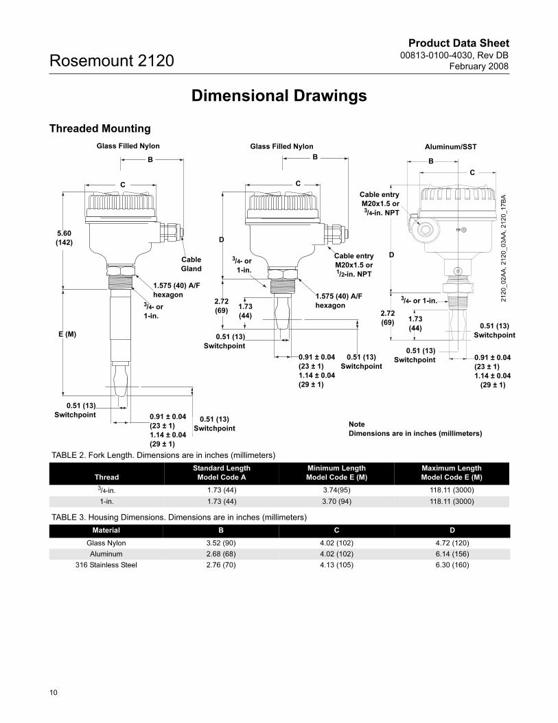
Dimensional Drawings
Threaded Mounting
Note
Dimensions are in inches (millimeters)
C
Cable entry
M20x1.5 or3/4-in. NPT
B
D
0.51 (13)
Switchpoint
B
C
D
2.72
(69)1.73
(44)
Cable entry
M20x1.5 or 1/2-in. NPT
1.575 (40) A/F
hexagon
0.91 ± 0.04
(23 ± 1)
1.14 ± 0.04
(29 ± 1)
0.51 (13)
Switchpoint
B
C
Cable
Gland
1.575 (40) A/F
hexagon
5.60
(142)
0.51 (13)
Switchpoint
0.91 ± 0.04
(23 ± 1)
1.14 ± 0.04
(29 ± 1)
0.91 ± 0.04
(23 ± 1)
1.14 ± 0.04
(29 ± 1)
1.73
(44)
2.72
(69)
E (M)
3/4- or 1-in.
Glass Filled Nylon Aluminum/SSTGlass Filled Nylon
0.51 (13)
Switchpoint
0.51 (13)
Switchpoint0.51 (13)
Switchpoint
3/4- or
1-in.
3/4- or
1-in.
2120_02A
A, 2120_03A
A, 2120_17B
A
TABLE 2. Fork Length. Dimensions are in inches (millimeters)
Thread
Standard Length
Model Code A
Minimum Length
Model Code E (M)
Maximum Length
Model Code E (M)
3/4-in. 1.73 (44) 3.74(95) 118.11 (3000)
1-in. 1.73 (44) 3.70 (94) 118.11 (3000)
TABLE 3. Housing Dimensions. Dimensions are in inches (millimeters)
Material B C D
Glass Nylon 3.52 (90) 4.02 (102) 4.72 (120)
Aluminum 2.68 (68) 4.02 (102) 6.14 (156)
316 Stainless Steel 2.76 (70) 4.13 (105) 6.30 (160)
10
Product Data Sheet00813-0100-4030, Rev DB
February 2008 Rosemount 2120
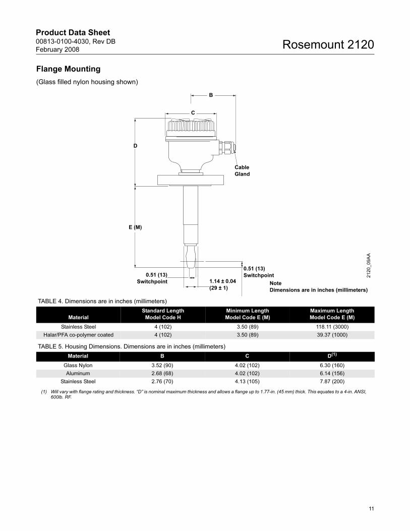
Flange Mounting
(Glass filled nylon housing shown)
0.51 (13)
Switchpoint
Note
Dimensions are in inches (millimeters)
D
1.14 ± 0.04
(29 ± 1)
B
C
Cable
Gland
E (M)
0.51 (13)
Switchpoint
2120_09A
A
TABLE 4. Dimensions are in inches (millimeters)
Material
Standard Length
Model Code H
Minimum Length
Model Code E (M)
Maximum Length
Model Code E (M)
Stainless Steel 4 (102) 3.50 (89) 118.11 (3000)
Halar/PFA co-polymer coated 4 (102) 3.50 (89) 39.37 (1000)
TABLE 5. Housing Dimensions. Dimensions are in inches (millimeters)
Material B C D(1)
Glass Nylon 3.52 (90) 4.02 (102) 6.30 (160)
Aluminum 2.68 (68) 4.02 (102) 6.14 (156)
Stainless Steel 2.76 (70) 4.13 (105) 7.87 (200)
(1) Will vary with flange rating and thickness. “D” is nominal maximum thickness and allows a flange up to 1.77-in. (45 mm) thick. This equates to a 4-in. ANSI, 600lb. RF.
11
Product Data Sheet00813-0100-4030, Rev DB
February 2008Rosemount 2120
Hygienic Fitting
(Glass filled nylon housing shown)
Note
Dimensions are in inches (millimeters)1.14 ± 0.04
(29 ± 1)
Cable
Gland
Cable
Gland
0.91 ± 0.04
(23 ± 1)
D
D
2.52
(64) 1.73
(44)
C
C
B
B
E (M)
0.51 (13)
Switchpoint
0.51 (13)
Switchpoint
B
C
D
Cable
Gland
1.575 (40)
A/F Hexagon
0.51 (13)
Switchpoint
3.07
(78)
0.91 ± 0.04
(23 ± 1)
0.51 (13)
Switchpoint
0.51 (13)
Switchpoint
0.51 (13)
Switchpoint
1.5-in. or 2-in.
Tri-Clamp
1.5-in. or 2-in.
Tri-Clamp
1-in. BSPP
O-ring seal
2120_05A
A, 2120_10A
A, 2120_20A
A
TABLE 6. Dimensions are in inches (millimeters)
Connection
Standard Length
Model Code A
Minimum Length
Model Code E (M)
Maximum Length
Model Code E (M)
Tri-Clamp 1.7 (44) 4.13 (105) 118.11 (3000)
O-ring Seal (1-in. BSPP) 1.7 (44) NA NA
TABLE 7.
Material B C D
Glass Nylon 3.52 (90) 4.02 (102) 4.96 (126)
Aluminum 2.68 (68) 4.02 (102) 6.14 (156)
Stainless Steel 2.76 (70) 4.13 (105) 6.54 (166)
12
Product Data Sheet00813-0100-4030, Rev DB
February 2008 Rosemount 2120
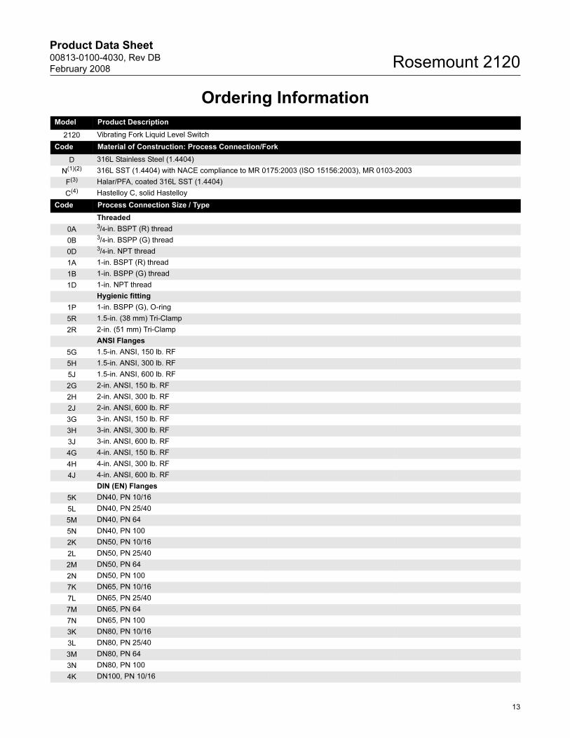
Ordering Information
Model Product Description
2120 Vibrating Fork Liquid Level Switch
Code Material of Construction: Process Connection/Fork
D 316L Stainless Steel (1.4404)
N(1)(2) 316L SST (1.4404) with NACE compliance to MR 0175:2003 (ISO 15156:2003), MR 0103-2003
F(3) Halar/PFA, coated 316L SST (1.4404)
C(4) Hastelloy C, solid Hastelloy
Code Process Connection Size / Type
Threaded
0A 3/4-in. BSPT (R) thread
0B 3/4-in. BSPP (G) thread
0D 3/4-in. NPT thread
1A 1-in. BSPT (R) thread
1B 1-in. BSPP (G) thread
1D 1-in. NPT thread
Hygienic fitting
1P 1-in. BSPP (G), O-ring
5R 1.5-in. (38 mm) Tri-Clamp
2R 2-in. (51 mm) Tri-Clamp
ANSI Flanges
5G 1.5-in. ANSI, 150 lb. RF
5H 1.5-in. ANSI, 300 lb. RF
5J 1.5-in. ANSI, 600 lb. RF
2G 2-in. ANSI, 150 lb. RF
2H 2-in. ANSI, 300 lb. RF
2J 2-in. ANSI, 600 lb. RF
3G 3-in. ANSI, 150 lb. RF
3H 3-in. ANSI, 300 lb. RF
3J 3-in. ANSI, 600 lb. RF
4G 4-in. ANSI, 150 lb. RF
4H 4-in. ANSI, 300 lb. RF
4J 4-in. ANSI, 600 lb. RF
DIN (EN) Flanges
5K DN40, PN 10/16
5L DN40, PN 25/40
5M DN40, PN 64
5N DN40, PN 100
2K DN50, PN 10/16
2L DN50, PN 25/40
2M DN50, PN 64
2N DN50, PN 100
7K DN65, PN 10/16
7L DN65, PN 25/40
7M DN65, PN 64
7N DN65, PN 100
3K DN80, PN 10/16
3L DN80, PN 25/40
3M DN80, PN 64
3N DN80, PN 100
4K DN100, PN 10/16
13
Product Data Sheet00813-0100-4030, Rev DB
February 2008Rosemount 2120
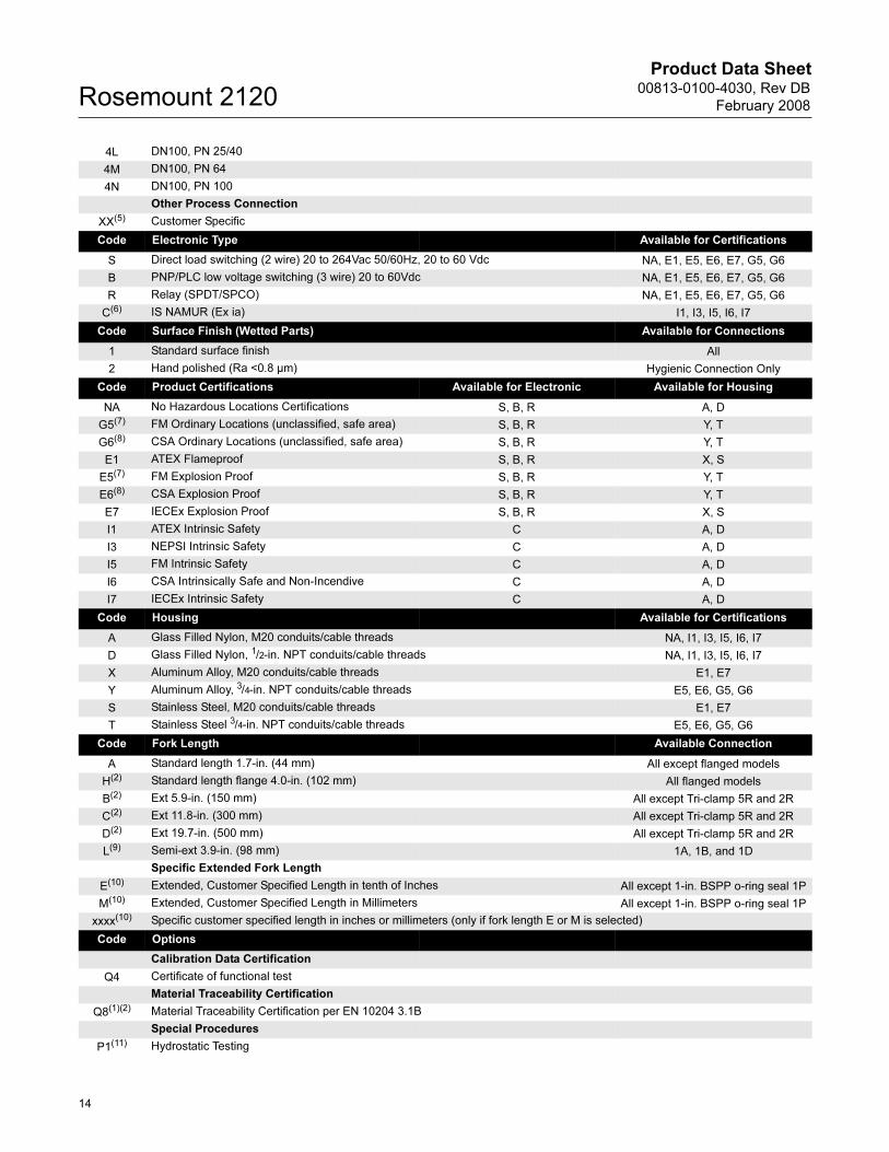
4L DN100, PN 25/40
4M DN100, PN 64
4N DN100, PN 100
Other Process Connection
XX(5) Customer Specific
Code Electronic Type Available for Certifications
S Direct load switching (2 wire) 20 to 264Vac 50/60Hz, 20 to 60 Vdc NA, E1, E5, E6, E7, G5, G6
B PNP/PLC low voltage switching (3 wire) 20 to 60Vdc NA, E1, E5, E6, E7, G5, G6
R Relay (SPDT/SPCO) NA, E1, E5, E6, E7, G5, G6
C(6) IS NAMUR (Ex ia) I1, I3, I5, I6, I7
Code Surface Finish (Wetted Parts) Available for Connections
1 Standard surface finish All
2 Hand polished (Ra <0.8 µm) Hygienic Connection Only
Code Product Certifications Available for Electronic Available for Housing
NA No Hazardous Locations Certifications S, B, R A, D
G5(7) FM Ordinary Locations (unclassified, safe area) S, B, R Y, T
G6(8) CSA Ordinary Locations (unclassified, safe area) S, B, R Y, T
E1 ATEX Flameproof S, B, R X, S
E5(7) FM Explosion Proof S, B, R Y, T
E6(8) CSA Explosion Proof S, B, R Y, T
E7 IECEx Explosion Proof S, B, R X, S
I1 ATEX Intrinsic Safety C A, D
I3 NEPSI Intrinsic Safety C A, D
I5 FM Intrinsic Safety C A, D
I6 CSA Intrinsically Safe and Non-Incendive C A, D
I7 IECEx Intrinsic Safety C A, D
Code Housing Available for Certifications
A Glass Filled Nylon, M20 conduits/cable threads NA, I1, I3, I5, I6, I7
D Glass Filled Nylon, 1/2-in. NPT conduits/cable threads NA, I1, I3, I5, I6, I7
X Aluminum Alloy, M20 conduits/cable threads E1, E7
Y Aluminum Alloy, 3/4-in. NPT conduits/cable threads E5, E6, G5, G6
S Stainless Steel, M20 conduits/cable threads E1, E7
T Stainless Steel 3/4-in. NPT conduits/cable threads E5, E6, G5, G6
Code Fork Length Available Connection
A Standard length 1.7-in. (44 mm) All except flanged models
H(2) Standard length flange 4.0-in. (102 mm) All flanged models
B(2) Ext 5.9-in. (150 mm) All except Tri-clamp 5R and 2R
C(2) Ext 11.8-in. (300 mm) All except Tri-clamp 5R and 2R
D(2) Ext 19.7-in. (500 mm) All except Tri-clamp 5R and 2R
L(9) Semi-ext 3.9-in. (98 mm) 1A, 1B, and 1D
Specific Extended Fork Length
E(10) Extended, Customer Specified Length in tenth of Inches All except 1-in. BSPP o-ring seal 1P
M(10) Extended, Customer Specified Length in Millimeters All except 1-in. BSPP o-ring seal 1P
xxxx(10) Specific customer specified length in inches or millimeters (only if fork length E or M is selected)
Code Options
Calibration Data Certification
Q4 Certificate of functional test
Material Traceability Certification
Q8(1)(2) Material Traceability Certification per EN 10204 3.1B
Special Procedures
P1(11) Hydrostatic Testing
14
Product Data Sheet00813-0100-4030, Rev DB
February 2008 Rosemount 2120
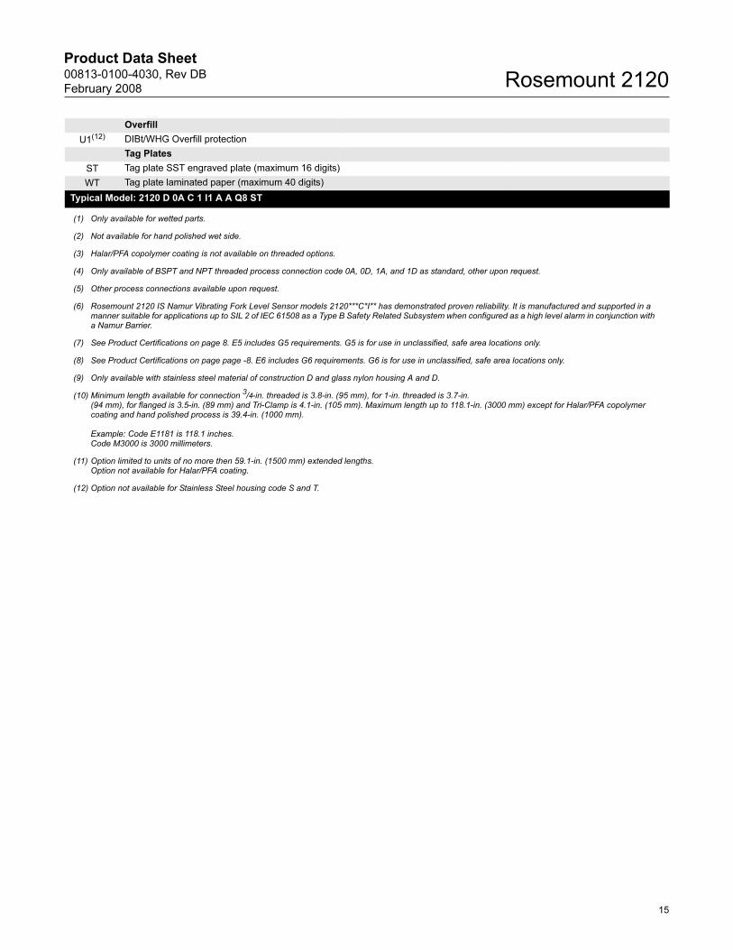
Overfill
U1(12) DIBt/WHG Overfill protection
Tag Plates
ST Tag plate SST engraved plate (maximum 16 digits)
WT Tag plate laminated paper (maximum 40 digits)
Typical Model: 2120 D 0A C 1 I1 A A Q8 ST
(1) Only available for wetted parts.
(2) Not available for hand polished wet side.
(3) Halar/PFA copolymer coating is not available on threaded options.
(4) Only available of BSPT and NPT threaded process connection code 0A, 0D, 1A, and 1D as standard, other upon request.
(5) Other process connections available upon request.
(6) Rosemount 2120 IS Namur Vibrating Fork Level Sensor models 2120***C*I** has demonstrated proven reliability. It is manufactured and supported in a manner suitable for applications up to SIL 2 of IEC 61508 as a Type B Safety Related Subsystem when configured as a high level alarm in conjunction with a Namur Barrier.
(7) See Product Certifications on page 8. E5 includes G5 requirements. G5 is for use in unclassified, safe area locations only.
(8) See Product Certifications on page page -8. E6 includes G6 requirements. G6 is for use in unclassified, safe area locations only.
(9) Only available with stainless steel material of construction D and glass nylon housing A and D.
(10) Minimum length available for connection 3/4-in. threaded is 3.8-in. (95 mm), for 1-in. threaded is 3.7-in.(94 mm), for flanged is 3.5-in. (89 mm) and Tri-Clamp is 4.1-in. (105 mm). Maximum length up to 118.1-in. (3000 mm) except for Halar/PFA copolymer coating and hand polished process is 39.4-in. (1000 mm).
Example: Code E1181 is 118.1 inches.Code M3000 is 3000 millimeters.
(11) Option limited to units of no more then 59.1-in. (1500 mm) extended lengths.Option not available for Halar/PFA coating.
(12) Option not available for Stainless Steel housing code S and T.
15
Product Data Sheet00813-0100-4030, Rev DB
February 2008Rosemount 2120
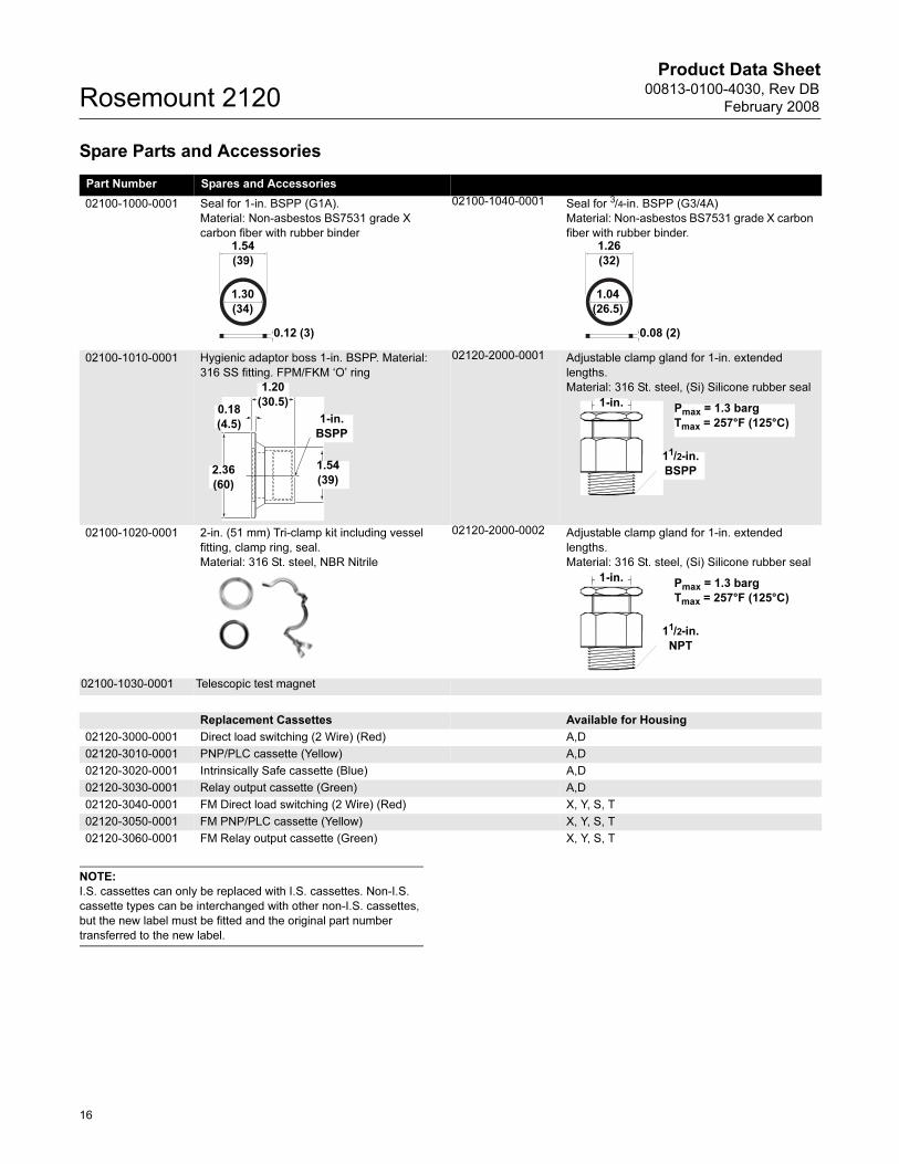
Spare Parts and Accessories
NOTE:
I.S. cassettes can only be replaced with I.S. cassettes. Non-I.S.
cassette types can be interchanged with other non-I.S. cassettes,
but the new label must be fitted and the original part number
transferred to the new label.
Part Number Spares and Accessories
02100-1000-0001 Seal for 1-in. BSPP (G1A).
Material: Non-asbestos BS7531 grade X
carbon fiber with rubber binder
02100-1040-0001 Seal for 3/4-in. BSPP (G3/4A)
Material: Non-asbestos BS7531 grade X carbon
fiber with rubber binder.
02100-1010-0001 Hygienic adaptor boss 1-in. BSPP. Material:
316 SS fitting. FPM/FKM ‘O’ ring
02120-2000-0001 Adjustable clamp gland for 1-in. extended
lengths.
Material: 316 St. steel, (Si) Silicone rubber seal
02100-1020-0001 2-in. (51 mm) Tri-clamp kit including vessel
fitting, clamp ring, seal.
Material: 316 St. steel, NBR Nitrile
02120-2000-0002 Adjustable clamp gland for 1-in. extended
lengths.
Material: 316 St. steel, (Si) Silicone rubber seal
02100-1030-0001 Telescopic test magnet
Replacement Cassettes Available for Housing
02120-3000-0001 Direct load switching (2 Wire) (Red) A,D
02120-3010-0001 PNP/PLC cassette (Yellow) A,D
02120-3020-0001 Intrinsically Safe cassette (Blue) A,D
02120-3030-0001 Relay output cassette (Green) A,D
02120-3040-0001 FM Direct load switching (2 Wire) (Red) X, Y, S, T
02120-3050-0001 FM PNP/PLC cassette (Yellow) X, Y, S, T
02120-3060-0001 FM Relay output cassette (Green) X, Y, S, T
1.54
(39)
1.30
(34)
0.12 (3)
1.26
(32)
1.04
(26.5)
0.08 (2)
1.20
(30.5)
1-in.
BSPP
2.36
(60)
0.18
(4.5)
1.54
(39)
1-in.
11/2-in.
BSPP
Pmax = 1.3 barg
Tmax = 257°F (125°C)
1-in.
11/2-in.
NPT
Pmax = 1.3 barg
Tmax = 257°F (125°C)
16
Product Data Sheet00813-0100-4030, Rev DB
February 2008 Rosemount 2120
17
Product Data Sheet00813-0100-4030, Rev DB
February 2008Rosemount 2120
18

Product Data Sheet00813-0100-4030, Rev DB
February 2008
19
Rosemount 2120
Product Data Sheet00813-0100-4030, Rev DB
February 2008Rosemount 2120
Emerson Process Management
© 2008 Rosemount Inc. All rights reserved.
¢00813-0100-4030V¤
Rosemount Inc.8200 Market BoulevardChanhassen, MN 55317 USAT (U.S.) 1-800-999-9307T (International) (952) 906-8888F (952) 949-7001
www.rosemount.com
Emerson Process ManagementHeath PlaceBognor RegisWest Sussex PO22 9SHEnglandTel 44 (1243) 863 121Fax 44 (1243) 867 554
Emerson Process Management Asia Pacific Private Limited1 Pandan CrescentSingapore 128461T (65) 6777 8211F (65) 6777 0947/65 6777 [email protected]
Rosemount and the Rosemount logotype are registered trademarks of Rosemount Inc.PlantWeb is a registered trademark of one of the Emerson Process Management group of companies.HART is a registered trademark of the HART Communication Foundation.Teflon, Viton ,and Kalrez are registered trademarks of Du Pont Peformance Elastomers.FOUNDATION is a trademark of the Fieldbus Foundation.DeltaV is a trademark of Emerson Process Management group of companies.Hastelloy is a registered trademark of Haynes International.Monel is a registered trademark of International Nickel Co.All other marks are the property of their respective owners.
Standard Terms and Conditions of Sale can be found at www.rosemount.com\terms_of_sale