
Roport/Artido TitlO Mass Spectrometric Studies: Final Report
228
Item IDNumber: 00057 Author Jones, E.G. CorDOratO Author Systems Research Laboratories, Inc., Dayton, Ohio Roport/Artido TitlO Mass Spectrometric Studies: Final Report Journal/Book Tltlo Year 1975 Month/Day Ju| v Color w Number of Imaoes 228 DOSCrlptOH NOtOll Contract No. F33615-73-C-4099; Report No. AFOSR-TR-73-1310 Friday, November 17, 2000 Page 57 of 60
Transcript of Roport/Artido TitlO Mass Spectrometric Studies: Final Report

Item ID Number: 00057
Author Jones, E.G.
CorDOratO Author Systems Research Laboratories, Inc., Dayton, Ohio
Roport/Artido TitlO Mass Spectrometric Studies: Final Report
Journal/Book Tltlo
Year 1975
Month/Day Ju|v
Color w
Number of Imaoes 228
DOSCrlptOH NOtOll Contract No. F33615-73-C-4099; Report No. AFOSR-TR-73-1310
Friday, November 17, 2000 Page 57 of 60

Jones, E.G. ,1975
Mass Spectrometric Studies
AD019521
i/UNLIMITED
TechnicalReport
distributed by
Defense Technical Information CenterDEFENSE LOGISTICS AGENCY
Cameron Station .Alexandria, Virginia 22314 ABROMEDICAL
JAN 11 1980
UNCLASSIFIED/UNLIMITEDDOCUMENTS

1.0
I.I
.25
t- S<£
ii2.2
2.0
1.8
1.4 i 1.6

AO-A019 5Z1
MASS SPECTROMETRIC STUDIES
E. G. Jones
Systems Research Laboratories, Incorporated
Prepared for:
Air Force Office of Scientific Research
July 1975
DISTRIBUTED BY:
KFuiNational Technical Information ServiceU. S. DEPARTMENT OF COMMERCE

-m. 75- 1 T> 1 0
Cft-p-i
i.
Approved for publladistribution unlimited. ; '
:.,.f '_-'' V--1
[j?,!7;JV' nj]ri
!j:'( JA>; 1973
D
NATIONAL TECHNICALINFORMATION 5ERVICE
of, VA
SYSTEMSRESEARCH
LABORATORIESINC.

CLASSIHCATION Of T M l S P A G t f»?i«n Pittn Kii
REPORT DOCUMENTATION PAGE READ ISSTRUCTKJCOMPI.P.TIN
MUMPER „ _ .i H - ? :> -1 -> i o i. oovt ACCESSION NO. 3. ReClf-lENT'S CATALOG
4.
88ASS SPECTROMETRIC STUDIES
$. TYPE OF REPORT t PtRlOO COVEREO
Finale. PcnroRMiMG ORC. REPORT NUMBER
7. AUTHORfaV
Dr.E. G. Jones
6. CONTRACT OR GRANT
F33615-73-C-4099
S. PERFORMING ORGANIZATION NAME AMD ADDRESS
Systems Research Laboi-atories, Inc.21600 Indian Ripple RoadDnyton, Ohio 45440
10. PROGRAM ELEMENT, PROJECT, TASKAREA & WC*RK UHfT NUM66HS
r 6H02F, 681303
U. CONTROLLING OTFICE NAME AND *DORCSS
AF Office of Scientific Rcsearch/NCBoiling AFB, Bldg. 410Washington, D.C. 20332
IZ. REPORT DATE
July 1975I). NUMBER OF PACES
t«.^MONITORING AGENCY NAME » AOOnESSfl* dl(/«fenl /roni Caiilroit'nd Citlitt) IS. SECURITY CLASS. (o( Ihlt
Unclassified15«. DECLASSIFlCATIOS OOWN5RAIT1
SCHEDULE
16. DISTRIBUTION STATEMENT (al fnli Kipott)
Approved for public release; distribution unlimited.
} '7. DISTRIBUTION STATEMENT («< me •htittcs «nt>r«<< in ojotk jo, n ain*t»ni from Htr>on>
»«. SUPPLEMENTARY NOTES
19. KEY *oftOS (Continue on ttvtut »in)« I/ nee««««ry «nd Idontlly 6y Woe
20! ABSTRACT fConllnu* on rfvcrit «lcl» II ,-<rcii>«<rv »nrf lrfcnl(f>' 6y tilocd num/ior>Hass'-spoctromctric investigations of diverse areas ranging from the basic under-standing of elementary physical.-chemical processes to analyses of trace eloncntsin the environment are outlined. Basic thermodynamics and chemical kinetics ofion-neutral phenomena relevant to the solution of problems of immediate Import-ance to the U.S. Air Force arc emphasized. Particular c-mphasis is placed onelectron-affinity determinations of small gaseous species of importance as elec-tron-affinity determinations of small gaseous species of importance as electron
JJAN*?! 1473 EDITION OF t N O V 6 S 14 OBSOLETE
I" SCCORIT" CLASSIFICATION OF TI.IS PAGE fi«ii»n />»'« l.nttna)
t •

SECURITY Ct*5SirtC*l lON Of THIS P»0tf«'h»n f*(*
20. Abstract • -scavengers in the atmosphere and electronic excitation in ion-neutralcollision processes of direct application to' the understanding and predic-tion of new laser systems.
Sophisticated analytical techniques to quantify trace contaminantssuch as diuxin in Herbicide Orange and other impurities in solid, liquid,and gaseous environmental samples ore outlined. These include samplework-up, column preparation, and gas-ehromatographic mass-spjctrometricanalysis.
Techniques for quantitative adsorption and desorption of noxious gaseson selectively prepared columns are described.
Methods of computer interfacing with mass spectrometers for dataacquisition are outlined. These include techniques for treating datafrom both chemical-physical and analytical investigations.
UNCL\SSIFIED 2<SECURITY CLASSIFICATION OF THIS PAGEWien £>•'•

tKiV, C.1
«)t$rs
Vt ;it'!
lil«T»!*S!IM
Ciil. '"*«.(. sr.l or
A
MASS Sl'ECTROMETRIC STUDIES
Final Report
Contract No. F33615-73-C-4099
Prepared for
Air Force Office of Scientific Research (OSR)Director of Chemistry1400 Wilson Boulevard
Arlington, Virginia 22209
•••.
D
(513) 426-6000
Prepared by
Systems Research Laboratories, Inc.2800 Indian Ripple RoadDayton, Ohio 45440 31 July 1975

TABLE OF CONTENTS
Section Page
INTRODUCTION 1
I. GAS-PHASE KINETIC? 3
II. CKQSSED-ION MOLECULAR-BEAM STUDIES „ 4
ION SOURCE AND LENS SYSTEM 4NEUTRAL-BEAM SOURCE 7PRODUCT-ION DETECTION SYSTEM 7
III. DEVELOPMENT AND APPLICATION OF ANALYTICAL METHODOLOGY ,FORDETAILED CHARACTERIZATION OF AIR FORCE HERBICIDE ORANGESTOCKS 8
INTRODUCTION 8DETERMINATION: OF 2,3,7,8-TETRACHLORODiBENzo-p-DioxiN
IN MILK 11DETERMINATION OF 2,3,7,8-TETRACHLORODIBENZO-p-DIOXIN
IN SOIL 15
IV. SPARK-SOURCE AND ELECTRON-IMPACT MASS-SPECTROMETRIC STUDIES 25 I
INTRODUCTION 25SPARK-SOURCE ANALYSIS 25ELECTRON-IMPACT MASS-SPECTRAL ANALYSIS OF GASES 29MASS-SFECTRAL ANALYSES OF OUTGASSING PRODUCTS FROM
TGG COMPONENTS 30FLAME-IONIZATION GAS-CUROMATOGRAPHIG.ANALYSIS OF .. . - .1
SOLVENTS . • ' 32ANALYSES OF SURFACE CONTAMINATION ON HYDRAULIC PISTON
FROM M-60 ARMY TANK IN CONNECTION WITH FLUID FAILUREPROBLEMS ' . 36
ANALYSIS OF M-60 TANK HYDRAULIC FLUID AND FLUIDCOMPONENTS 39
V. DEVELOPMENT OF SOLID SORBENTS FOR MONITORING WORK-PLACEPOLLUTANTS: NITROGEN DIOXIDE <H02) AND NITRIC OXIDE (NO) 45 (
INTRODUCTION 45NITROGEN DIOXIDE (N02) 48NITRIC OXIDE (NO) 72
VI. INSTRUMENT-COMPUTER INTERFACING AND PIOGRAMMING 99 ( 2 O
MS-30 ' 99SPARK-SOURCE MASS SPECTROMETER 100CROSSED BEAM AND CD-491 PROGRAMS 101OTHER COMPUTER WORK 101LIST OF PROGRAMS 102
REFERENCES ' 107 (lib
PUBLICATIONS RESULTING FROM THIS CONTRACT 110
4<ii

LIST OF ILLUSTRATIONS
Page
Ar* Kinetic Energy Distribution, Nominal Energy2.4 and 3.7 eV . 5
2 Ar* Kinetic Energy Distribution, Nominal Energy 10.5 eV 6
3 Alumina-Silica Gel Combination Column 13
4 Extract - Dow Method Cleanup 16
5 Extract - Milk Extraction Method Cleanup 17
6 Freon "" 33
7 Is op ropy 1 Alcohol from Druta 34
8 Isopropyl Alcohol from Vapor Booth 35
9 Schematic Diagram of the Adsorption-Desorption Apparatus 47
10 Desorption of NO- as a Function of N02 Concentration 56
11 Recovery of NO as n Function of NO Concentration andAmount of Molecular Sieve 5A 80
• •- .f, '
12 NO Recovery as a Function of NO Concentration UsingAmbient Air as Sampling Mixture Gas 86
13 Recovery of NO as a Function of NO Concentration UsingTEA-P205-Molecular Sieve 5A Column 90
iii 5<

LIST OF TABLES
Table Pgge
I TETRACaORODIBENZO-p-DIOXIN LEVELS IN SOIL SAMPLESFROM ECLIN AIR FORCE BASE, FLORIDA 24
II SSMS ANALYSIS OF BERYLLIUM-BEARING SURFACES 26
III SSMS ANALYSIS OF DEPOSITS ON MICROSCOPE SLIDES 27
IV SSMS ANALYSIS OF"STATORS AND EPOXY 28
V PERCENTAGE OF C02> TOLUENE, AND FREON FOUND IN GAS SAMPLES 31
VI MASf-!;PECTROMETRTC .ANALYSIS OF M-60 FLUIDS 41
VII REPRODUCIBILITY OF NO SORPTION WITH MOLECULAR SIEVE 5ACOLUMN 55
VIII EFFECT OF MOISTURE ON N02 RECOVERY 58
IX N02 STORAGE EXPERIMENT DATA 62
X RECOVERY OF NO AS A FUNCTION' OF THE AMOUNT OF MOLECULARSIEVE 5A 81
XI REPRODUCIBILITY CF NO SORPTION WITH MOLECULAR SIEVE 5ACOLUMN 84
XII NO STORAGE EXPERIMENT DATA 87
XIII STORAGE OF NO SAMPLE UNDER ABNORMAL CONDITION 89
iv

ABSTRACT
Mass-spectrometric investigations of diverse areas tanging from the
basic understanding of elementary physical-chemical processes to analyses
of trace elements in the environment are outllived. Basic thermodynamics
and chemical kinetics of ion-neutral phenomena relevant to the solution of
problems of immediate importance to the U. S. Air Force are emphasized.
Particular emphasis in placed on electron-affinity determinations of small
gaseous species of importance as electron scavengers in the atmosphere and
electronic excitation in ion-neutral collision processes of direct appli-
cation to the understanding and prediction of new laser systems.
Sophisticated analytical techniques to quantify trace contaminants such
as dioxin in Herbicide Orange and other impurities in solid, liquid, and
gaseous environmental samples are outlined. These include sample work-up,
column preparation, and gas-chromatographic mass-spectrometric analysis.
Techniques for quantitative adsorption and desorption'of noxious gases
on selectively prepared columns are described.
Methods of computer interfacing with mass spectrometers for data
acquisition are outlined. These include techniques for treating data from
both chemical-physical and analytical investigations.

INTRODUCTION
The objective of this program was the development and utilization of
advanced mass-spectrometric techniques for the study of fundamental
analytical and physical-chemical problems of interest to the U.S. Air
Force. The fundamental areas investigated in the course of this contract
include: (1) ion-neutral collision studies involved in the determination
of basic thermochemical quantities such as t-.lectron affinities of
refractory metal oxides; (2) development of chemical and tnass-spectrometric
procedures for determining 2,3,7,8-tetrachlorodibenzo-p-dioxin in Air
Force Herbicide Orange and environmental matrices; (3) spark-source
mass spectrometric analysis of solid sampler of interest to the Air Force;
(4) development of mass-spectrometric techniques for studying sorption
of noxious gases by selected solids; (5) high-resolution mass-spectrometric
analysis of liquid and gaseous samples, and (6) development of an
operating interface between laboratory Instruments and computer.
The scientific investigations were performed in the Gaseous Excitation
and lonization Processes Group, Chemistry Research Laboratory, Aerospace
Research Laboratories, Wright Patterson Air Force Baset Ohio, utilizing
the unique instrumentation fabricated during the initial phase
of this contract and other sophisticated equipment located in this
laboratory.
The authors would like to acknowledge the cooperation of Dr. Thomas
0. Tiernan and co-workers at the Aerospace Research Laboratories and
the efforts of R. P. Clow, C. A. Davis, C. E. Hill, Jr., J. C. Haartz
Smith, and M. L. Taylor during the early phases of the program.
8-

This report describes in detail the work perf or. .ed during the past
four months and summarizes the results obtained over the entire course
of the contract.

SKCTICfJ I
CAS-PHASE KINKTICS (
During the course of this program a number of thermodynaralc and
kinetic studies have been completed. In these ntudiea, both tandem
and time-of-flight mass spectrometers have been used as well as
instruments for monitoring the luminescence produced in ion-molecular
interactions. Much of this work faro been documented in Systems Research
Laboratories, Inc., annual and semiannual, progress reports.
Extensive work completed since publication of these reports has
resulted in several manuscripts which have been prepared for publication
in various scientific journals. This nectlon is comprised of these
manuscripts; ea.?h manuscript is a self-contained unit having its own page,
reference, table, figure, and equation nunbers.
10-

0.6
0.5(VJ
Q0.4f-
cnCO0'3enoo:^0.2
.0!
0 0 o o
o
0° 0
XIO
DD
pi1 ""
! 1 1 10 20 40
fc I- #U
60 80 100 120 140 i60 180He ENERGY (eV.lab)

0,3
°<0.2
OLUcnenCO
(J
0
oo
oo
o o
10 20 30 40 50 60
HE+ENERGY(eV,lab)70 80

CJ
Oh-QUJCO
COOtr
0.4-
03--
0.2-o o
t I
° °
t I
20 40 60 80 100 120 140 160 180
He* ENERGY (eV,iab)
K-C..A

u.a
OJ*"*o< no— O.2z:Q0
enen8'Qio:o
0.0
.(
He++CH4 — -La °
o o0
o— o
o
o •o
~ o:O ° '•
Q&
0 1 1 I 1 I I I JD 20 ' 40 60 -80 100 120 140 160 18<
£ He+ ENERGY (eV,!ab)A

Lyraan Radiation From He /Molecule Interactions
B, M. Hughes and T, 0. Tiernan
Aerospace Research Laboratories, LJWright Patterson Air Force Base, Ohio 45433
E. G. Jones
Systems Research Laboratories, Inc.2800 Indian Ripple RoadDayton, Ohio 45440
Introduction
In this laboratory extensive investigations of the luminescence
produced in ion-neutral collisions have been undertaken. The studies
have emphasized the low kinetic energy region (1-200 eV) in which &
significant number of electronically excited product species are formed.
Certain of these states can radiate. By monitoring the luninescence,
information concerning the interaction of an ion and a neutral can be
ascertained. In.particular, information concerning the energy
distribution of reaction products can aid in the design of potential laser
systems. Ion-neutral reactions in certain cases have been found to be
an efficient laser-pumping mechanism.
Low-energy collisions of He ions with hydrogen-containing molecules
frequently produce H atoms in a series of excited levels. For example,
reaction of 100 eV, lab He ions with a hydrogen molecule has been shown
to produce H(n) for n » 2,3,4,5,6 as determined by monitoring the subsequent2
Lyman or Balmer radiation from these states. In this kinetic energy
region, the intensity of the luminescence is strongly dependent upon tbe
2 3kinetic energy of the colliding partners. " Production of all of these
excited states of the hydrogen atom is cndocrpic for thermal energy2
collisions. In a companion study conducted in this laboratory, the
individual kinetic energy onsets for H(n); n * 2,3,4 were determined.
15-
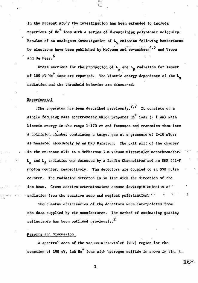
In the present study the Investigation had been extended to include
reactions of He ions with a scries of H-conCaining polyatomic molecules.
Results of an analogous investigation of L emission following bombardment
by electrons have been published by McGowan and co-workers * and Vroom
and de Keer.
Cross sections for the production of L and L. radiation for impactct P
of 100 eV He ions ore reported. The kinetic energy dependence of the I,
radiation and th>* threshold behavior are discussed.
Exper imen tal
2 7.The apparatus has been described previously. ' It consists of a
single focusing mass spectrometer which prepares He ions (- 1 nA) with
kinetic energy in the rangu 1-170 cV and focusses and transmits them into
a collision chamber containing a target gas at a pressure of 2-10 mTorr
as measured absolutely by an MKS R.iratron. The exit slit of the chamber
, is the entrance slit to a McPherson 1-m vacuum ultraviolet monochromator.
L and L0 radiation was detected by a Bendix Channeltron" arid an EMR 541-Fa P
photon counter, respectively. The detectors are coupled to an SSR pulse
counter. The radiation detected is in line with the direction of the
ion beam. Cross section determinations assume isotropic" emission of
radiation from the reaction zone and neglect polarization'. '
The quantum efficiencies of the detectors were interpolated from
the data supplied by the manufacturer. The method of estimating graf.ing2
reflectance has been outlined previously.
Resul ts and Disciission
A spectral scan of the vacuum-ultraviolet (VUV) region for the
reaction of 100 eV, lab He ions with hydrogen sulfide is shown in Fig. 1.
16-

The jfirst three members of the Lyman series are Indicated in the figure.
Because c€ intensity considerations, cross sections only for L and Lft
are reported. The emission cross section for a series of reactions of
100 cV, Inb He ions are summarized in Table I. In each case L and L0o P
emission linos are the dominant features of the VUV region. No corrections
for cascading have been applied. The relative intensities, however, imply
that: these effects would be negligible for these systems. It should be
pointed out that only cmissi'-ns from short-lived (< 1 us) excited species
would be monitored by this apparatus. The metastable state 11 (2s) would not
be detected. Only in the case of the hydrogen reaction are absolute
cross-section data available in the literature. As discussed in the
2previous study on hydrogen, the cross section for L emission is in
3excellent agreement with the data oC Dunn, et al. The cross section tor LQ—— — p
i3 approximately 2.5 times smaller than the value determined by Gusev,Q
e_t _al. For all of the polyatomics studied, the cross section for L"•""~" *~"""* ct
emission exceeds that for L0 emission by a factor ranging from 5 to 25.p
The level H(3) lies 1.8C- cV above H(2) for an isolated H atom. The
differences in the cross sections reflect the probability of producing
11(3) and 11(2) in a reaction at 100 eV.
In general, the larger polyatomics exhibit considerably smaller cross
sections for H-atom excitation. Overlooking ,hydrogen which has been treated2
previously, the largest cross sections for L emission arise from the
reactions with ILS, H^O, NH. and CH,. The kinetic energy behavior of the
cross section for Lyman alpha production in these four reactions is
displayed in Figs. 2-5. All of these reactions exhibit similar kinetic
energy dependence in that there is a threshold region below which the
17<

readion is of low probability and above which the reaction cross acetic
increases monotonically to the highest energy studied. The cross section
lor Lyman alpha emission in the reaction with H-S appears to remain
approximately constant in the vicinity of 100-150 cV, lab. The cross
sectional dependence of the Lyinan beta emission shown In Fig. 2 displays
a similar kinetic energy dependence.
Two factors combine to tnf.ke a precise kinetic cncrpy threshold deter-
mination difficult except in favorable cases. First, below 10 oV, lab
there is a gradual decrease in ion flux through the collision region* resulting
in large correction to the observed counting rate. The second effect is
related to the instrument geometry. The in-line geometry allows the
detection of some reactive events occurring in the deceleration lens
9which is adjacent to the collision chamber. Corrections for this; usually
amount to - 20-40% of the observed count rate for 100 eV He ion impact.
The absolute magnitude of thlu correction does not change appreciably
over the entire kinetic energy region; however, this results in a very
poor signal-to-noise ratio at kinetic energies in the vicinity of the
onset. This necessitates longer counting intervals. The kinetic
energy thresholds, estimated from Figs. 2-5, are summarized in Table II.
No attempt to correct for the doppler effect or the primary-ion energy
spread has been made. Because of the relative masses of the rcactants,
calculated enthalpy changes are listed in Table II for two possible
excitation reaction steps
He"*" + R-H •> R+ + H(2p) + He (1)
He* + R1-" * R1+ + H(2p) + H + He (2)

It is not possible in those experiments to distinguish between Reactions (1)
and (2). For example, interaction of 30 cV, lab He ions with CH,
produce CH, , CH_ , CH ', CH , and C+ ionic products. Although CH
is the most abundant ion product, no direct correlation between H(2p)
and a specific ion product can be made. For 100-eV iona striking CH,, the
cross section for Lynian alpha production is 0.2 A ; this may or may not be
comparable to the cross section for CH. or OIL formation. There is no
absolute data available in this energy range.
A strong analogy exists between the results of this study and the
+ 2He /H_ system. All of the kinetic studies indicate endoergic excitation
processes. In these systems th« transfer of kinetic into reaction
energy to produce excited product species is important. Very selective
reaction channels appear to be available which are determined by symmetry
considerations. As more data become available on the partitioning of
kinetic energy into reaction channels, it becomes quite clear that
frequently the most probable channels involve excited electronic states
of the products.

REFERENCES
1. A. R. Turner-Smith, J. M. Green, and C. E. Webb, J. Phys. (B):Atom.
Molec. Phys. 6t 114 (1973).
2. I'. M. Hughes, E. G. Jonas, D. C. Hopper, and T. 0. Tiernan,
submitted for publication,
3. G. H. Dunn, R. Ceballo, and D. Pretzer, Phys. Rev. 128, 2200 (1962).
4,, J. W. McGovan and J. F. Williams, Abstract:a of VI International
Conference^ on the Physics of. Electronicjand Atomic Collisions
(MIT Press, Cambri !ge, Mass., 1969).
5. J. W. McGowan, J. F. Williams, and D. A. Vroom, Chenu Phys.
Lett. 3,, 614 (1969).
6. D. A. Vroom and F. J. de Heer, J. Chcm. Phys. 50, 18G3 (1969)
and references therein.
7. B. M. Hughes, E. G. Jones, and T, 0. Tiernan in Abstracts of
VIII Internattonal Conferenco on t ho Phys ica of Klectronic^and
Atomic ColIisiQna. Vol. I (B. C. Cobic and M. V. Knsepa, .Eds.) i
(Institute of Physics, Beo&rad, Yugoslavia, 1973) p. 223.
8. V. A. Gusev, G. N. Polyakova, V. F. Erko, Ya. M. Fogel, and A. V. Xnts
in Abstracl:^ of^ thc VI JEnteriiationfij Conforence on the Physics of
Electronj.c^_ai\d Atojnlc Cojllisions (MIT Press, Cambridge, Mass., 1969).
9. E. G. Jonesi B. M. Hughes, D. C. Fee, and T. 0. Tiernan, submitted
to Chem. Phys. Lett.
10), H. A. Bethe, Rev. Mod. Phys. 9., 69 (1937).
11. J. L. Franklin, J. G. Dillard, H. 1'.. Rosenstock, J. T. Herron, K. Draxl,
and F. H. Field, National Bureau of Standards Report NSRDS-NBS 26, 1969.
12. H, Von Koch, Arkiv Fysik 28, 529 (1965).

Species
H2
D2
V
H20
CD4
C2H2
C3»8
Table 1
EMISSION CROSS SECTIONS, 100 cV lie*
He* + M + L, L
Cross Section
o(cm )
0.46
0.69
0.54
0.31
0.23
0.20
0.20
0.09
0.039
0,037
0.013
s(x 1Q18)
1.7
2.7
3.1
1.6
1.5
2.0
1.7
1.3
0.51
0.67
0.15
Ratio
3.7
3.9
5.7
5.2
6.5
10.0
8.5
14.0
13.0
18.0
12.0
21-

Table II
KINETIC KNERCY THRESHOLDS FOR LYMAN ALPHA EHISS10KS
Enthalpy ChangeKinetic Energy Threshold to Form 11 (2p)
Syjtem . (e\Q
He4 4- CH4
He4" 4- H2S
He"*" 4- NH3
He 4- H20
5 +
5 ±
2.6
6.1
1.6
1.8
± !•<»
± 1.6
-0.
4-0.
4-1.
4-3.
08b.*
OSN
39
91
b.
t,if
4-5
4-3
+3
4-8
.34c
.61°
.65
.85
c
Heats of formation based on tabulation.'! of Rcf. 11.
Calculation assumes reaction of the form
He"*" 4- R-H -> R*" 4- H(2p) 4- He
Calculation assumes reaction of the form
He* 4- K'-H2 -* Rt+ + II 4- Ii(2p) 4- He

roCO
LUh-
40
30
LU> 20
LUo:
10
Li
lOOeV
Y •i/ RELATIVE
/ SPECTRAL/ RESPONSE
/ OF SYSTEM
H
^If'k^^^v^120 105 90 75 60WAVELENGTH (nm)

COLLISION-INDUCED DISSOCIATION OF CO-
Richard L. C. Wu
Sya terns Research Laboratories, Inc.2800 Indian Rippld RoadDayton, Ohio 45440
T. 0. Tiernan
Aerospace Research LaboratoriesChemistry Research Laboratory
Wright Patterson Air Force Base, Ohio 45433
ABSTRACT
Collision-induced dissociation reactions of the molecular negative .
ion CO, impacted on various target gases (He, Ne, Ar, Kr, Nc, N_, 0_
and N0«) have been Investigated in an in-line tandem mass spectrometer.
These processes exhibit cndothormic thresholds. The energy dependences
of the cross sectionn are compared with these predicted by the statistical
theory. The dissociation energy of the molecular ion CO- was deter-
mined from the measured energy threshold and v.is used to calculate the ._' *'
electron affinity of CO.. molecule-.

'" INTRODUCTION
Keecntly, the collisional phenomena and thermochemistry of the CO,*"
ion have been subjects of extensive investigation because of their
12" • • 3 Aimportance in the fields of aeronomy ' and radiation chemistry. *
The dissociation energy of o""-CQ_ has been measured by various researchers ' *
and found to vary from 1.8 to 2.0 eV and the electron affinity of CO,O "J
has been calculated and found to range from 1.8 to > 2.9 eV. The
techniques used in the experiments reported above were photodetachment,
photodissociation, and flowing afterglow processes.
In the present study, the tandem mass spectrometer was used to study
the energy dependence of the cross section for collision-induced
dissociation (CID) of CO- upon various target molecules. The post-
threshold behavior of these processes was compared with the predictionq
of the statistical theory of Robick and Levine. The energy dependence of the
cross section is assumed to have the form A(E ~E ) /E .., where E and
E , are respectively the total energy and the relative transitional
energy of the reactants and E is the threshold energy. The exponent n
depends upon the mechanism of the process, with 1.9<n< 2.2 for a "direct"
mechanism and 1.5 <n< 1.8 for an "indirect" mechanism. For a given
CID reaction, the calculated threshold function was convoluted, with the1
calculated center of mass energy distribution arising from the '•herraal
motion of the target molecules and the energy spread of the incident-ion
beam. The calculated curves were then fitted to the. experimental cross
section to obtain the true energy threshold and the appropriate values
of n. The dissociation energy of CO, was then determined from the
energy thresholds and was used to calculate the electron affinity of
the CO molecule.

EXPERIMENTAL
The experiments were conducted using a recently modified in-line
tandem mass spectrometer. The instrument has been described
previously. * ' As a result of the installation of a 1000 ft/sec
oil diffusion pump and tlie reduction of the size of the electron-entrance
and ion-exit slits, sufficiently high pressures can be achieved in the
first-stage ion source to generate the secondary or high-order ion
products of ion-neutral collisions. The mass- and energy-analyzed primary
ions were injected into the field-free collision chamber containing
various target molecules. The product ion was then analyzed by the
second-stage mass spectrometer which was fixed at 0° scattering angle.
Pulse-counting techniques were used to measure the product ion currents.
The temperature of the collision chamber was maintained at 160°C in
the experiments reported. The energy spread of the ion beam was about
0.3 eV (lab), over the energy range 0.3-180 eV.
The primary ion of CO- was formed by electron impact on a gaseous
mixture of CO^ and N?0 at high pressures. Currents of COu generated
in this manner were on the order of 50-200 PA. Tn order to ascertain
whether a single collision had occurred in the collision chamber, the
pressure of the target molecules was varied from 10-50 n. All reactions
showed a linearity over this pressure range. The experiments were carried
out at a pressure of 50 u in order to obtain reliable cross sections.
All cross sections were evaluated relative to the absolute cross section
°2 - _ 13of 63 A at 0.3 eV 0 energy for the 0 /N0_ charge-transfer.

MUtLYSIS OF DATA
Jjhnreshold^Behavior
Theoretical predictions * as well as experimental studies *
of the threshold behavior for CID reactions involving a colliding
pair (A + BC) which yields three products (A + B + C) have shown this
behavior to have the form
(1)
E , E .» and E having been defined previously and A being a function
of the internal energy of the reactant (BC). Thus, the cross section
would be zero at the threshold and would increase monotonically with
the kinetic energy of the reactant according to the mechanism of the
process. If the experiment were carried out at an infinite translational
energy resolution, the experimental data could be parameterized according
to Eq (1), from which the values of A, E, and E would be obtained.
However, in the present study a distribution exists in the, effective
center of mass energy. Hence, the results were treated as described
below.
Corrections for Energy Resolutions
Two factors limit the energy resolution in the present experiments —V,' •
principally, the thermal motion of the target molecules and the ion
energy spread of the incident ion beam. The former effect is well-known
as Doppler broadening. The energy distribution caused by the thermal
motion of the target molecules in a system vhere the monoenergetic
iora beam collides with target molecules having a Maxwellian distribution
18has been discussed and derived in detail by Tiernan, Hughes, and Lifshitx.
£7-

The" effective energy distribution in the laboratory system is expressed"«» ' •
by
1/2where A = 2 (mEj.KT/M) ' is the Dopplcr width as well as the half-width
of the probability distribution at 1/e of the maximum height, m and H
are the masses of the ion and target molecules, respectively, T \a the
temperature of the target molecules, E. is the translational energy of
the ion beam, and K Is the Boltzmann's constant. However, in the tandem
mass spectrometer used in this study the distribution of the energy
spread in the incident ion E . has been found to . be a Gaussian function with
a full-width at half-maximum (FWIIM) of - 0.3 cV. Thus the energy
distribution of E, is assumed to be
with the most probable value being K. =E. . Therefore, the effective
energy distribution in the laboratory system arising from both the thermal
motion of the target molecules and the energy spread o£ the incident
ion beam becomes
+«,
W(E') - f W(E'/E) WCE) dE (4)
The distribution of Eq (4) is, in general, broader than that of Eq (2)
It is notable that those collisions which involve a relatively heavy
ion and light target molocules arc those for which Doppler broadening
is most severe, e.g., for the CO. /No collision, the effective energy

distribution of Eq (4) is nearly the same as that of Eq (2). On the
other hand, for the reaction of a relatively light ion with a heavier
neutral target such as C03~/Xc, the ion energy spread [Eq (2)1 will play
a more important role in the final evaluation of the" energy distribution
in the system.
Typical results obtained from the calculation described are
illustrated in Fig. 1 for the CO, /Xc collision at an CO-" laboratory
energy of 3.6 eV and a temperature of 160°C. Fig. l(a) shows the
energy distributions of Eq (2) (solid lines) and Eq (4) (dashed lines).
Figure l(b) shows the ion energy spread of Eq (3). It is shown that
the effect of the ion energy spread on the total effective energy
distribution is less important than that of the Doppler broadening in
this study. The FWHM of the effective energy distribution in the
laboratory energy for the CID reactions of CO- are found to be 0.88, 1.25,
2.13, 3.50, 2.69 and 2.75 eV, respectively, for the target molecules
of Xe, Kr, Ar, Ne. 0_ and N2>
Techniques Used
A convolution technique was utilized in. the analysis given below*
The energy dependences of cross sections was computed by convoluting
the above effective energy distribution [Eq (4)] with the-assumed threshold
function f(E') according to
f(E) dE = I f(E') V(E') dE1 (5)' J"

In the present study the statistical theory was adopted in order to
describe fetes behavior of the cross section (zero value at threshold—no
step) . Ifte reactants and the products were assumed to be in the ground
state and A to be independent of the CO.," initial state; therefore, the
assumed threshold function f(K') is simply
f (E') - A(E« - Eo)n/E» (6)
For a given CID process using Eq (6), the computed threshold functions
having different values of E and n were then convoluted with the calculated
effective energy distribution {Eq (4)]. These calculated curves were
then compared with the experimental results to obtain the true threshold
energy (E ) and the appropriate value of n.
RESULTS AND DISCUSSION
TranslatiQnal Energy Dependence of the Cross^Jfection
The cross section for the CID reactipn
CO " + X ->• 0~ + CO, + X (7)o &
was studied as a function of CO, ion translational energy for various
target molecules, and results are shown in Fig. 2. In these reactions,
typical endothermic behavior is exhibited. In the region near thei' ,,,<;>i ;i <
threshold (- 1.8 eV), the energy dependence shows an exponential increase
(no sharp step) followed by a linear rise to a maximum (~ 6 eV (CM)) and
then a gradual decrease. Thus, the statistical prediction of the
threshold behavior was utilized to describe the experimental observations.

'S Figure 3 shows the calculated cross section ns n function of laboratory
energy (solid line) for the CID of CO- impacted on various target
molecules. These curves were obtained by convoluting the energy-
distribution functions with the assumed statistical threshold functions
(dashed lines); experimental data points are also shown. It was found
that a good fit to the experimental results could be obtained over the
entire energy range of 2-6 eV (CM) with appropriately chosen E and n.
The uncertainty of the values of E and n is on the order of + 0.1.
Table I contains the values of E and n which give the best fit to the
experimental data. Values of E obtained from photodissociation measurements
made by various researchers are also included for comparison purposes.
The exponent n given in Table I varied from 2.0 to 2.5; according to
the statistical theory, these CID processes are direct mechanisms—not
totally unexpected in view of the structure of the CO- ion. The
ground state of CO, is believed to be a trigonal structure having C~
18symmetry with an 0-C-O valence angle of - 120". Hence, it is
unlikely that an intermediate complex is formed during the collision
process.
The dependence of the coefficient A in Eq (1) upon internal energy
of the reactant has been shown to affect rcmarkedly the CID reaction cross
9 19 • 'sections. ' In general, the cross sections should increase and th?
translational energy threshold decrease as the reactant vibrational
excitation increases. In recent photodiusociation experiment by Cosby
20and Moseley, the possibility of the existence of some vibrational
excited states of the CO- was discussed. However, as shown in
Fig, 3, excellent fit to the experimental data was obtained for various

target molecules by assuming A to be equal to a constant and no apparent!
lower the translational energy threshold was observed. Thus, the effect'
on coefficient A due to the vibrational excitation of the initial CO,,
ion, if any, may not be important in the present study.
Therniochemistry
It is assumed that neither the reactants nor products are in the
excited states at the threshold. The average bond dissociation energy
of cT-COo was calculated to be 1.95 + 0.1 eV from a total of six experi-
ment involving various target molecules. This value is in excellent
agreement with the. photodissociation values of - 1.8 eV found by
Beaty ct al.,5 1.86 + 0.01 eV by Vestal et al.,6 1.93 by Cosby et al.,2°
21and - 2.0 eV by Moselcy ct al. This value is also in excellent
agreement with the flowing afterflow value of 2.0 + 0.2 eV found by
Ferguson et al.
In the present study, the formation of CO takes place by electron
.impact on the gaseous mixtures of N«0 and C0?, whereas, in a number of
photodissociation experiments, it takes place by electron impact onft 01
pure C02 (Vestal and Moselcy ) and by electrical discharge on the
gaseous mixture of CO, and 0 (Beaty ). Although the source of the
formation of the CO. ion is different in these experiments, the
observed thresholds are the same within experimental error. This leads
to the conclusion that the C0~ ion formed in the present experiment
is indeed in the ground state.
The heat of formation of C0~ can be calculated from the thermodynamic
cycle as follows

4- X -»• 0" -f C02 I- X AHjj - 1.95 (8)
then, AHR - Allf (o") + AHf(CO,,) - AHf(C03").
Thus,
AHf (C03~) » AHf(0~) + AHf(C02) -
» 1.05322 - 4.07822 - 1,95
-4.98 + 0.1 eV
The heat of formation of the CO- molecules is tqual to -43 + 5 kcal/raole
(-1.864 + 0.22 cV). Thus, the electron affinity of C0» may be calculated
from
EA(C03) - AHf(C03) - Allf(C03~) (9)
= -1.864 + 4.98 » 3.1 + 0.2 eV
which is comparable to the lower-limit value of 2.9 eV reported by
Ferguson et al. who used the flow-afterglow technique, and to the21
lower-limit value of - 2.7 eV reported by Moseley et al. who used the
' ' 8photodetachment technique. The value of 1.8 eV reported by Burt is
• • ' ..... .. . . . . . T -•••'•- •believed to be too low for the same reason given by Ferguson et al.
who suggested that photodissociation instead of photodetachment may have
occurred in Burt'n experiment. Ferguson's argument has been confirmed
21by Moseley et al. who recently repeated Burt's experiment.
The charge-transfer process,
CO" + NO •> NO ~ -f products AIL = 1.3 + 0.2
was also found In the present investigation to be endothermic by
1.3 + 0.2 cV, as shown in Fig. 4. By assuming the reaction according to
10

C03 4- N02 * N02 + C03 Ah^ -1.3 (11)
23and taking the electron affinity of NO, to be 2.3 cV, the electron
affinity of C0« was calculated to be
EA(C03) - EA(N02) + Ah^
- 3,6 + 0.2 eV
which is greater (by 0.5 eV) than the value of 3.1 + 0.2 eV found from
the dissociation energy of C0_ . However, if the above charge-transfer
reaction occurs as
C03~ + N02 •> N02~ + 0 -»- C02 AHR - 1.3 (12)
then, the heat of formation of CO ~ is calculated to be -5.0 + 0.2 cV,j ~~
which is in excellent agreement with the value of -4.98+0.1 eV
determined from Eq (8) in the present study. This provides an internal check
on the thermochemieal process. The heat of formation of C03 is AH, =
-1.864 + 0.2 eV, which leads to D(0 - C0») =,0.39 +0,22 .«V; for the above«~ ^ — •• . -
charge-transfer proems (10) , the reaction (12) is probably more favorable
than the reaction (11).
CONCLUSIONS • ..... '.•.,
The collision-induced dissociation of C0_ has been shown to exhibit
endothermic thresholds. The threshold behavior agrees well with the
prediction of the statistical theory, the exponent n ranging from 2.0 to
2.5. These processes proceed through a direct mechanism. The bond-
dis&ociatlon energy and heat of formation of C0« are determined to be
1.95 + 0.1 and -4.98 + 0.1 eV, respectively, and the electron affinity
of CO- is calculated to be 3.1 + 0.2 eV. "7tl<.
11

REFERENCESt
1. D. K. Bohroe, D, B. Dunkdn, F, C. Fehsenfeld, and E, E. Ferguson,
J, Chem. Phys. SI, 863 (1969).
2. N. C. Adams, D. K. Bohme, D. B. Dunkin, F. C. Fehsenfeld, and
E. E. Ferguson, J. Chem. Phys. 52, 3133 (1970).
3. D. A. Parkes, J. C. S. Faraday 1 68, 627 (1972).
4. A. R. Anderson and J. V. F. Best, Radiat. Chem. j2, 231 (1968).
5. Beaty, Mitchell and Woo, private communication.
6. M. J. Vestal and J. Futrell, private comr.unlcation.
7. E. E, Ferguson, F. C. Fehsenfeld and A. V. Phelps, J. Chem.
Phys. 59, 1565 (1973).
8. J. A. Burt, J. Chem. Phys. 57., 4649 (1972).
9. C. Rebick and R. D. Levine, J. Chem. Phys. _58, 3942 (1973).
10. J. It. Futrell and C. D. Miller, Rev. Sci. Instr. 37_, 1521
(1966).
11. B. M. Hughes and T. 0. 1'iernan, J. Chem. Phys. 55 , 3419 (1971).
12. T. 0. Ticrnan and R. E. Marcottc, J. Chem. Phys. J>3, 2107 (1970).
13. J. L. Paulson, Advan. Chora. Ser. 58, 28 (1966).
14. R. D. Levine and R. B. Bernstein, Chem. Phys. Lett. 11, 552 (1971).
15. E. K. Parkes, A. Wagner and S. Wexler, J. Chem. Phys. J58, 5522
(1973).
16. W. B. Maier, J. Chem. Phys. 4JL, 2174 (1964); J. Chem. Phys. 42_,
1790 (1965).
17. P. J. Chantry, Bull. Am. Phys. Soc. _16, 212 (1971); J. Chem. Phys.
55, 2746 (1971).
12

18. M. E. Jacox and D, A, MUligan, J, Mol. Spcctrosc, 52, 363 (1.974).
19. E. K. Parkes, A, Wagner, and S. Wexler, J. Chcm. Phys, _58, 5502
(1973).
20. P. C. Co$by and J. T. Moseley, to be published in Phys. Rev. Lett.
21. J. T. Moseley, P. C. Cosby, R. A. Bennett, and J. R. Peterson,
to be published in J. Chcm. Phys.
22. J. L. Franklin, J. C. Dlllard, 11, M. Rosenstock, J. T. Herron,
K. Draxl, and F. H. Field, Ionizat_ign Jfo entiajls, Appearance
Potentials, and Heats, j f. Formation of^ C ase pus o sj tlye Ions
(U.S. Dept. of Commerce, National Bureau of Standards,
Washington, D.C., 1969).
23. B. M. Hughes, C. Lifshiftz, and T. 0. TIernan, J. Chem. Phys.
59, 3162 (1973).
13

•*» FIGURE CAPTIONS
*Fig. 1. (a) Calculated relative energy distributions, W(E'/K.)
(solid line) and W(E') (dashed line), for the reaction
pair C03~/Xe at 3.6 eV C03"" laboratory energy at 433°K.
(b) Calculated relative energy distribution, W(E.), for
the incident ion energy npreud.
Fig, 2. Energy dependence of the cross section for the collision-
induced dissociation reaction of CO., with rare gaa atomic
and molecular targets. The base lines for some experiments
are shifted as indicated in the graph.
Fig., 3. Calculated cross section aa a function of laboratory energy
(solid Itncs) for CID reaction of CO- on various target
molecules at 433°K; obtained by convoluting appropriate
energy distribution functions with iitntiRtic.il threshold
functionn (dashed lino). Points are experimental data.
Fig. 4. CRoss section (arbitrary units) as; a function of nominal
center of mass energy (cV) for the re-action
CO ~ + NO -> NO " + products.•5 JL 2,
37"

Table 1*i
Best fit valucfi of K and n obtained by convoluting o»A(E-E
with the energy dint filiation for the collision-induced dissociation of
co o" •»• co
TargetGas
Xe
Kr
Ar
Ne
°2
N2
n
(± 0.1)
2.2
2.0
2.2
2.0
2.4
2.5
Ko(+ 0.1 eV)
1.9
1.9
1.9
2.0
2.0
2.0
Ave.,.1.93
E0 (Lit.)
1.85
1.86 + 0.016
* 1.9J20
- 2.021
2.0 + 0.27
08-

1.0
§ 0.8
crccCDCC
g
i
0.6
0.4
0.2o:o-JUJcc-
0
003+ N02—- NOg-f- PRODUCTS
Q
I0.57 1.14 1.71 -2.29 256
CENTER OF MASS ENERGY( eV)
3.43 4.00

cA
CO 3 +X 0 + C02 +X
o-A(ErE0)n/Et Xe 02
3.0 2.OZA 2.5
EotCMM.9n-2.2
6 8 10 12 14003 ION ENERGY Et (eV.LAB)

3-6
3.2
2B
2.4
S4c2X)
§ l.a
0.4
T I I I I "T003 +x
Ooo Np(+l.oA2)
XX A
He (+0.72 A2)
N02{ + 0.56A2)
n
0 4 6 8 10 12CENTER OF MASS ENERGY (eV)

U
LJ
UJtr
(b)
1
A
4 5 2 3 4CO! LABORATORY ION ENERGY (eV)

CHARACTERIZATION OF THE POTENTIAL ENERGY SURFACE OF THE
xVc2!!) STATE OF' O".*
Richard t. C. Wu*
Systems Research Laborator"=s, Inc.2800 Indian Ripple RoadDayton, Ohio 45440
T. 0. Tiernan
Aerospace Research Laboratories (LJ)Wright Patterson Air Force Base, Ohio 45433
D. G. Hopper and A. C. Wahl
Chemistry DivisionArgonne National LaboratoryArgonne, Illinois 60439
Work partial]-/ performed under the auspices of USERDA and Air ForceContract MT.PR899474 00117, Amendment 1.
TPresent address: Department of Chemistry, Wright State University,Dayton, Ohio 45431.
43-

ABSTRACT
Collision-induced dissociation of N^O by six rare gas and diatomic
target gases yields an average value of 0.43 + 0.1 eV for the dissociation
energy D(N_—-0*"). This measurement along with literature values for other
quantities leads to an electron affinity of 0.22 +0.1 eV and a trend
dissociation energy D(N-NO ) of 5.13 + 0.1 tV. These values pertain to the
X2A' ground state of N90". Ab initio LCCG-MO SCF and OVC-MCSCF calculationsi» "' *"~* "" VL*~* "*"""' *"*•" . .
'on the potential energy surface of this state show that it has a minimum
in C symmetry with an N-N-0 angle near 125*. The geometry of eachs
minimum has N-N and N-0 bond lengths that are approximately 5 and 15%
greater, respectively, than the bond lengths in neutral NjD (X Z ). The
computed minimum energy geometry at the SCF level with a better thano
double-zeta quality basis set is, within a precision of 2%, R =1.20 A,o
R.,=1.38 A, ()„...= 124°. The valence force field force constants forNO NNO
N-N stretch, for N-0 stretch, and for bending are found to be 11.5,
3.9, and 0.65 md/A, respectively, at this geometry.
44<

1. INTRODUCTION*
2 2The potential energy surface of the X A'( H) ground state of the
nitrous oxide negative ion N_0 has been of 'some concern in recent
years. ~ This molecular system is interesting in that the possible
ionospheric associative detachment reaction
0"(2P) •*• N2(X1J:g> •> N20(X
1j;'*"> + e + 0.21 eV (1)
2—6is not observed in laboratory experiments at 300°K. The upper bound
-13 3to the thermal rate constant has been placed at 10 to 1x10 cm /s by
2 3 5 *various experiments. * ' The origin of the low thermal rate for this
exothermic reaction may be discussed in terms of the characteristics of2
this X A' ground state potential energy sjrface. This surface connects
adiabatically to tho reagent asymptote, 0~( I'), N,(X £*). The effects* 8
of Increased vlbrational temperature, which is common in the ionosphere
but which has not been investigated in laboratory experiments, can also
'be discussed in terms of this potential surface. Knowledge of this
Surface can also contribute to the understanding of the, recombination
reaction
0~(2P) + N2(xV) -' N20~(X2A') (2)
Q
and the dissociative attachment reaction
1 :*) + e -> Nn(xV) -f 0~(2P) (3)
This paper presents some experimental and theoretical studies conducted
~ 2to characterize the N2G (X A1) potential energy surface. The results
of collision-induced dissociation cxperimentr, including corrections
for Doppler motion and ion energy spread arc prc-.sent'od in Section 2,
' 45-

:JPaifollowed fay a presentation of nb lnljj.10 LCBF-MQ-SCP and OVC-MCSCP calegations
in Section 3. Section 4 is n discuuolon of the present results including
comparisons with previous work. Conclusions arc then nuuh. in Section 5.
2. COLLISION-INDUCED DISSOCIATION AMI) CHAKGE-EXC.HANGEEKPERIMENTS WITH N "
A. Apparatus
The ARL in-line tandem mass spectrometer was utilized in this study.
12 13The instrument has been described previously. * In brief, it consists
of two double-focusing mas>s spectrometers connected by a field-fcee
collision chamber. The primary ion is formed in the ion source of the
first stage mass spectrometer which produces a mass and energy analyzed
beam. In this study the primary ion of N~0 was formed by electron impact
on N?0 molecules at high pressures (- 0.1 u):
N2° N2° N2°N20(X
1J:+) + e -v N20"*(X2A') —*• —> .. . »• N^xV) (4)
-AIt is estimated that N.O suffered approximately ten collisions within
JL -, * t , . . . . ,.,,
the source chamber and that exiting N20 was, thus, predominately in the
ground vibrational state. The energy spread of the ion beam is about10 13
+ 0.3 eV (LAB) over the ion energy range 0.3 to 180 eV (LAB). ' The
second stage mass spectrometer was ufit:d to analyze the masses of the
product ions formed in the collision chamber. Pulse counting techniques
were used to measure the product ion currents. The collection stage in
this instrument is fixed at 0° (LAB) scattering angle. The temperature
of the collision chamber was maintained at 160°C and the pressure was
varied from 10 to 40 M. The product ion 0 signal intensity was linear
over this target gas pressure, range indicntinp, that singlu bimo.1 ocular
collision events N«0 -t- M prevailed. The experiments with the various
target gases were, thus, carried out at. a target gas pressure of 40 jt

in the collision chamber in order to obtain n high o" product ion
intensity while yet maintaining single collision conditions. Production
intensity Ip was converted to on observed cross section a . via the
relationship
where I^CEj ) is the primary ion intensity and n is the target pressure.
The conversion factor a was determined from the reported absolute cross
section (63 A , Reference 14) and the observed product ion intensity at
0.3 eV reactant ion energy E. (LAB) for the charge transfer reaction
0"(2P) -f N02(X2AA) -»• 0(31») + N02~(X
1A1> + 0.8i eV (6)
See Fig. 1.
B. Threshold Behavior and Corrections for the Ion EnergyDistribution and Dopplcr Motion
The threshold behavior of the total cro'ss section o 'for collision
induced dissociation reactions
PxS + M •» M r R -I- S (7)
is known from theoretical considerations and experimental studies
to be well approximated by the functional form
(8)
In Eq (8) E is the total energy (C.O.M.) and K } the relative
translational energy of the reactants; E is the threshold total energy.
The exponent n depends upon the mechanism of Reaction (7): the range
47 <

1.9 £ n < 2.2 corresponds to a direct process, and the range l.S < n < 1.8
n15
% 15to an indirect process. The coefficient A Is n function of the Internal
energy of the reactant RS.
In the present beam-chamber experiments the observed cross section
is related to the absolute cross section by the integral equation
-/%bs<Eio> - dE
where E. is the set-point of the ion beam energy in the laboratory frame,
E. is the laboratory energy of the ions moving along the axis directed
through the collision chamber, u is the speed of the target molecule M
along the same axis, and £(EjJE ) is the distribution function for the
ion energy about the set-point E. . The latter function is assumed to
be of the form
(air)"1 cxpt-(E ~ E> 2/a*l dl- (10)
where the parameter a is determined to be 0.2 by the requirement that the
half-width-at-half-maximum be 0.3 eV. It is further assumed in Eq (9)
that f(u ) is the one-dimensional Moxwellian distribution of target gas
molecular speed um
i/o 1 9f (uj - On kT/'2 cxpC- -f mm U//RTJ dum (11)
with m being the mass of the target molecule, k, Boltzman's constant, and
T the target gas temperature. Lastly in Eq (9), E . is the centor-of-
mass collision energy
4fc<

with the reduced mass y find ion speed u being
u± - (ZB mp (14)
and m. being the ion mass. The ion energy distribution function of
f(E |E. ) given in Eq (10) has been previously established for the ARL
12 13tandem mass spectrometer. * The absolute cross section a , (E ,) is
assumed to have the form of Eq (8) ; since the reagent molecules are taken
to have no internal excitation the total energy E reduces to E ,. In
some places this function is compared to experiment on the laboratory
energy scale with all energy of motion attributed to the ion
El " VW Erel <15)
in which case the mass factor is rained to the (n-1)' power multiplied
into the constant factor A to form a new constant A'.
o(E ) - A'(Ej-K0)n/Kj (16)
In this case, of course, F, is obtained in tlio laboratory scale. Optimum
values of the parameters E and n arc determined for each target gas by
means of a grid search procedure. Visual comparisons of plota of o , (EjQ
as evaluated from Eqs (8)-(l4) with the observed data were made for all
combinations of n = 2.1, 2.2, 2.3, 2.4, and 2.5 for E (COM) * 0.3, 0.4,
0.5, 0.6 eV.

C. Results •
A lower bound of cheater than zero for the electron affinity for N-O
wa#r established fey the observation of m/e = 44 negative ions from -electron
impact on N-0 gas.
An upper bound to the electron affinity of N-O was established by
ft study of the cross section for the charge transfer reaction
N20"(X2A') + 02(Kh~&) -> 02~(X
2Hg) + NjjCKX1!*) (17)
The results are shown in Fig. 1 along with the standard charge transfer
Reaction (6). The cross section for Reaction (17) was found to decrease
monotonically with the trnnslational energy of the incident N^O ion
from tba lowest energy obtainable, 0.3 eV, to above 8 eV. This result
Indicates that Reaction (17) is exothermic and that the electron affinity
of N»0 is•• smaller than the electron affinity of 02. The electron
affinity of 0, has been determined to be 0.45 + 0.1 eV by various
20researchers using differing techniques.
Direct determinations of the N--0 bond dissociation energy — and,
thence, the electron affinity and the N-NO bond dissociation energy were
then undertaken. The cross section o(E ) the collision-induced dissociation
Reaction (/), where R « N and S = 0 , was measured as a function of
the nominal ion energy E for each of various target molecules M = Xe,
Kr, Ar, Ne, He, and N,,. The results arc shown in Fig. 2. All of these
reactions exhibit thresholds and, thus, may be expected to be endoergic.
In Che threshold region the cross sections show exponential increase,
followed by a linear rise to a maximum, and then a gradual decrease. In
order to obtain the true energy threshold for each reaction the convolution
50-

teeSlinique described above in Eqs (8)-(14) was employed to resolve the* i1
energy distribution resulting from the thermal motion of the target
Ktolecules M (Uoppler correction) and the energy spread of the incident
ion beam. In Fig. 3 the calculated cross sections (Eq (9)] for 0*" from
NgO _ Ne at 433*K are drawn as solid lines for various combinations of
E and n. Visual comparisons with the data, which are shown as solid
points, show that the computed curve with E = 0.4 eV and n = 2.3 is the
best fit. The uncertainty in the values of E and n is on the order of
+ 0.1; these error limits art: estimated from'the ranges of E and n which
yielded a gtod fit to the experimental data. Figure 4 compares the best
fit curves [Eq (9)] for all of the target molecules The values of E
and n defining these best fits are tabulated in Table I. The dashed lines
in Figs. 3 and 4 are the unconvolutcd cross section functions [Eq (16)].
From Table I the average value for the bond dissociation energy
D(N2-Q ) is 0.43 Hh 0.1 eV. This result is based on the assumption mentioned
above that neither the reagent nor the product molo.cu.les are internally
3 20excited near threshold. The electron affinity of 0( P) is 1.47 cV and
21the dissociation energy I)(N2-0) is 1.68 eV. From these values the
electron affinity of N,C(X1J:4') is 0.22 + 0.1 cV. The bond dissociation/2 ?1
energy D(N-NO) and the electron affinity of N0( II) arc 4.93 cV " and
20 -0.02 eV, respectively. Thus, the bond dissociation energy D(N.-NO )
is 5.13 + 0.1 eV.
51-

3. AB IM1TIO DETERMINATION OF THE EQUILIBRIUM GEOMETRY ANDFORCK "CONSTANTS OF N,0~
A. Method of Calculation
2 2Calculations on the potential energy surface of the X A'( H) state
of NjO were carried out with both a single (SCF) and a multi-configuration
(MCSCF) wave function. The calculations were made with the BISONMC and
22 23 24 25POLYINT codes ' with 4s3p contracted Gau0»lan basis sets. The SCF
determinant was
7 9 9 0 9 9 0 9 9 ')')')C : la1 Za' a' a1 5a'*6a' 7a' 8a' 9a' lOa'^la" 2a"8 (18)
9 ? 9 7 ? ? ? ? 7 7 9C : lcT20 3a 4a 5a 6a lir ,7a 2n 3" lit 2Tt
The MCSCF wave fur~tion was developed for the linear TT state by the
sequential consideration of doubly excited configurations to correlate the
8a, 9a, and 3ir orbitals. The 15 configurations of the present MCSCF
wave function are listed in Table II alonj; with their weighting coefficients
at selected geometries. While the MCSCF configuration list has not been
2optlmizt-d at a geometry n.ar the minimum of the- X A' potential surfr.ee,
it should be indicative of the effects cf correlation upon the minimum
located in the extensive scan with the single determinant wave function.
The MCSCF molecular orbitals are presented In Tables Ilia and Illb at
the first and third geometries of Table II.
B. SCF Equilibrium Geometry and Force Constiints
The SCF bending curves at various combinations of bond lengths
(RM>., R o) arc displayed in Fig. 5(a). These results, along with an
examination of those of Fig. 5(b) as they wore; obtained, indicate an
equilibrium geometry near 125° with R ,N = 1.03 UJL and R 0 - 1.15 R^j ,
10

f 'where R , and R Q are the equilibrium values for K20(X
1E"t"). Figs. 5(b)
fond 5(c> give tho SCF miiximura at R^« 2.27 a.u., R »2.60 a.u., and
0 »31240. The valence field force constants, at this geometry arc
shown in Table IV. The bending force constant is computed as the second
derivative of the bending potential in Fig. 5(c) divided by the bond
lengths given above from Fig. 5(b). Tho. bond stretch force constants
were computed as the second derivative of the potential curves given
in Fig. 5(b).
G. MCSCF Bending Curves
The bending curves obtained with the above described 15 configuration
MCSCF wave function are shown in Fig. 6. Comparison of these curves with
the corresponding SCF curves in Fig. 5(a) shows that the correlation
energy added by the 14 extra configurations in the present MCSCF wave
function do not have a strong effect on the geometry and shape of the
potential minimum. This is, of course, to be expected from the high
coefficient of the main configuration. See Table II. The MCSCF and SCF
potential energy surfaces are compared in Table IV.
4. DISCUSSION
A. Interpretation of the Collision-Induced DissociationResults in Terms of Theory
The statiscicnl theory derived by Rebick and Levine is found to
'satisfactorily describe the threshold behavior of the collision-induced
dissociation reactions of N~0 impacted on five rare gas and N~ diatomic
molecules. The exponent » given in Table I ranges from 2.3 to 2.5 for
the various target gases. This range is larger than the upper limit of
2.2 givon by Rcbick and Levine, but it is contained by the upper limit
11

26derived by Lcvine and Bernstein. By comparison a range 1.4 to 2.3 was
16 • 1 ftreported by Maier and by Parks, Wagner, and Wcxlcr from their studic
i<D£ the collision-induced dissociation of positive ions. According to the
statistical theory leading to Eq (9) the collision-induced dissociation
reactions of N_0 examined in the present work are direct processes.
That these processes do not involve the formation of an intermediate
collision complex is not totally unexpected since the target gases employed
were composed of closed shell molecules of essentially zero electron
affinity.
B. Electron Affinity of N,0
The electron affinity of the N0Q molecule has been determined by
various groups using different experimental techniques. A tabulation
of these studies is displayed in Table V. That the adiabatic electron
affinity might be positive while the vertical electron affinity remained4
negative was suggested in 1967 by Ferguson, Fe.hsenfeld and Schmeltekopf.
Bardsley concurred in his molecular 6rbital' analysis in 1969. In 1971o
Wentworth, Chen and Freeman reported an adiabatic electron affinity of
0.3 + 0,2 eV from thermal electron attachment rate experiment. Kalleyq
et al. reported a lower bond of -0.15 HH 0.1 cV from their cesium
collisional ionization experiments.in 1973. Tiernan and Clow report
0.6 eV from collision-induced dissociation experiments, but they made no
correction for the ion or the tnrftot ion velocity distributions. From
the present experiments one can see that N_0 is not motastable since its
detection in the second stage mass spectrometer implies a lifetime of
greater than 50 iisec. Also, as discussed previously, observation of the
54-

charge transfer Reaction (6) establishes the electron affinity as less
than that of 02> 0,45 + 0.1 eV. The present collision induced dissociation
result of 0.22 + 0.1 eV» which has been corrected for the ion and
product molecule energy distribution, is in excellent agreement with the8 ' ' "." "
result of Wentworth ct al.
C. Equilibrium Geometry of tfre X A1 State of N,o"
the presently reported equilibrium geometry (Table IV) is the best; . 4
available to date. A suggestion that the equilibrium angle would be
close to that of the isoelcctronic neutral molecule NO- - 134* - is about
10° too high. From Figs. 5(a) and 6 this latter overestimate may be seen
to be attributable to an approximately 10* decrease in the bending
potential minimum upon stretching the N-N and N-0 bond elengths about
10% each from the neutral equilibrium values.o
The statement by Wentworth et al. in the abstract of their paper
that they determined the equilibrium angle to be about 160° appears to
be an inadvertent error. These authors actually assume an equilibrium
value of 134° in the analysis of their data to determine the electron
affinity tabulated in Table V. From the text of their paper the 160°
figure corresponds to the threshold bending angle for thermal electron
~ 2attachment — i.e., for a crossing of the N20(X'£) and NJ3 (X A1) potential
energy surfaces at near neutral equilibrium values for' the' bond lengths.
D. Contour Plots of V C R , 0 ) f°r N2cf (X2A') and
oWentworth, Chen, and Freeman employed a parameterized Morse function
which may be written
13

•wi*
•where f(0) is, determined from the assumption that
<20)
and the parameters r>Nl!5_0» &« and k depend, in turn, implicitly upon
R N(X1E"*'). Wentworth et al. wroteone such Eq 09) for N20(X
1X+) and
"2 ' 21one for N_0 (X A'), took literature values for the NJ) parameters,
assumed 0® = 134" for NJ)", D Q_ « DNN_0
a 3-^ eV and determined
k for N20" by requiring that the lowest crossing point (R , °NNO)thrcshold
of the two surfaces occur at an energy 0.45 + 0.02 cV above the zero
point energy of N^O. The latter energy is the activation energy that
8Wentworth et al. determined from their measurement of the temperature
dependence of the rate of Reaction (3) in the range -66 to 215°C. The
results of the present study can be employed to establish all the parameters '
in the Eqs. (19-20)as written for N O and to determine the crossing threshold locu,
(IW °NNO*threshold and activation energy with respect to zero point N20
independently of the experimental determination of Wentworth et al. A
comparison between the. predicted and measured thresholds will then serve ':
as a check on the- appropriateness of the parametric potential function
form given by Eqs. (19-20). The implicit treatment given K Nin -Kq,(19) may be
justified on the grounds that it increases but 5% in going from NJJ to
NJ3 , and the decreases to 2% less than the N«0 equilibrium value on
decomposition to N^+0 . The parameters are summarized in Table VI. The
56-14

2functions f (<*NNO) have been fit to the functional form a +• bO +• cO
?where the constants a, b, and c are included in Table VI. Figure 7 is
a combined contour map with the function V(R Q, 0 Q^ ) for N20~(X A1)
(dashed contour lines) on top of that for N20(X I ) (solid contour lines).
The crossing locus is shown by the symmetric pair of dash-dot lines.
5. CONCLUSION
2 2 -The potential energy surface of the X A'( II) state of N«0 is stable in
its equilibrium region with respect to either dissociation or detachment.
The key quantities required to characterize this surface have been
determined and are summarized in Table VII. In addition a value of
0.22 + 0.1 eV was established for the adiabatic electron affinity of N0.
15 57<

REFERENCES
1. J. F. Paulson, Adv. Chcm. Scr. 58, 28 (1966).
2. F. C. Fehsenfold, E. E. Ferguson, and A. L. Schmeltekopf, J. Chcm.
Phys. 45, 1844 (1966).
3. F. Kaufman, J. Chew. Phys. 46, 2449 (1967).
4. E. E. Ferguson, F. C. Fehsenfeld, and A. L. Schmeltekopf, J. Chera.
Phys. 47, 3085 (1967).
5. J. L, Moruzzi, J. W. Ekln, mvd A. V. Phclps, J. Chcm. Phys. 48,
3070 (1968).
6. P. J. Chantry, J. Chcm. Phys. 51, 3380 (1969).
7. J. N. Bardsley, J. Chcm. Phys. J51, 3384 (1969).
8. W. E. Wentworth, E. Chen, nnd R. Freeman, J. Chetn. Phys. J5J5,
2075 (1971).
9. S. J. Nalley, R. N. Compton, H. C. Schweinler, and V. E. Anderson,
J. Chem. Phys. £9, 4125 (1973).
10. T. 0. Tiernan and R. P. Clow, Adv. Mass Spect. J5, 295 (1974).
11. M. Krauss, D. G. Hopper, P. J. Fortune, A. C. Wahl, and T. 0. Tiernan,
"Potential Energy Surfaces for Air TrlaComics. Volume I. Literature
Review," ARL TR 202, Vol. I, Air Force Systems Command, June 1975.
Available from the National Technical Information Service, U.S.
Department of Commerce, Springfield, Vn. 22151.
12. T. 0. Tiernan and R. E. M«rcottc, J. Chcm. Phys. 53, 2107 (1970).
13. B. M. Hughes nnd T. 0. Tiernan, J. Chcm. Phys. 55_, 3419 (1971).
S8-16

• * " • • ' . ' ' - 914. This value has been deduced from the thermal rate constant of 1.2x10
* 'cm /uwolccule-sec reported in Reference 1 frou the equation k •* "5v,
Ihfi O" velocity was computed asv » (2E/ra) ' at E»0.3 eV (LAB),
15. E, Rebick and K. D. Levine, J. Chem. Phys. 5£, 3942 (1973).
16. W. B. Maier II, J. Chem. Phys. 41, 2174 (1964).
17. W. B. Maier II, J* Chem. Phys. 4j2, 1790 (1965).
13. E. K. Parks, A, F. Wagner, and S. Wexler, J. Chem. Phys. 58,
5522 (1973).
19. R. L. C. Ku and T. 6. Tiernan, ''Collision-Induced Dissociation of
C03~\" in preparation (1975).
2°« CRC Handbook of Chemtstry^ ajid Plryslcs , 55th Edition, edited by
R. C. Ucast, CRC Press, Cleveland, 1974-1975, and references
listed therein.
21. G. llerzberg, EJec t ronj c^pcctrtT nnd_ JSlcc trqni c
Poly a t oni I c . Mo.lecul e_s , Van Nostrand, Princeton, 1966.
22. G. Das and A. C. Wahl, "BISON-MC" A FORTRAN Computing System for
Multiconflt'.uration Self-Consistcnt-Fleld (MCSCF) Calculations on
Atoms, Diatoms, and Polyatoms," Argonnc National Laboratory
Technical Report, ANL-7955 (1972). For availability, see
Reference 11.
23. D. Neuman ct al., "POLYATOM (Version 2)," Quantum Chemistry Program
Exchange Indiana U., Bloomington, Indiana. PA300 was modified and
linked to BISON-MC by A. Hinds of Argonne National Laboratory.
The modified version, which generates canonical lists of integrals
amd no labels, is referred to as POLYINT.
17

24. T. H. Dunning, Jr., J. Chora. Phys. S5, 3958 (1971).
25. S. Huzinaga, J. Chcm. Phys. 42, 1293 (1965).
26. R. D. Levirae and R. B. Bernstein, Chcm. Phys. Lett. 11, 552
(1971).
27. E. B, Wilson, J. C. Decius, and P. C. Cross, Molecular yibratiojr.s.
The Theory of Infrared ajuj Raman Vibratiqnal Spectra. McGraw-Hill,
New York, 1955, p. 176.

FICUR.E CAPTIONS
Figure 1. Charge transfer cross sections for 0*"/NO_ (•) and N?0 /O
<«).
4.
Figure 2. Collisloa-induccd dissociation cross sections of N»0 to
N2 + 0 by target gas molecules X = Xc, Kr, Ar, No, He, and N2-
Figure 3. Optimization of the parameters E and n for m « Ne. The effect
of the variation of n is shown for three values of E . The
curves for E a0.3 and E =0.5 are off -set 4 and 8 eV,
respectively, on the energy scale for clarity of presentation.
The solid points are the data from Figure 3. The dashed
lines are for Eq (16) . The solid lines are for Eq (9) . The
near Gaussian distribution curve centered about E. a 3 eV
(LAB) is for the combined distribution function fo»f(E./E ) f(u )
with which Eq .(.16) is convoluted in Eq (9) in order to compute
an "observed" cross section for direct comparison with the
unadjusted experimental data.
Figure 4. Comparison of the Eq (9) optimum computed values (solid lines)
for 0 (E. ) with the uncorrected experimental values (solidODS XO
symbols) for target gases Xe (*) , Kr (B), Ar «»)» N2 (A), and
Ho. (€)). The optimized values for E and n in Eq (16) areo
shown for each collision gas. The dashed lines are from Eq (16).
Comparison of the solid and dashed lines provides a visual
indication of the Importance of the combined Doppler and ion
energy spread effects upon the cross section for 'the various
target gases.
19

Fijjwre 5. (a) Bending potential energy curves for N2o"(X A1) with
An SCF wave function and o As3p basis set. Cruves
arc drawn for combinations of the two bond lengths
ranging from 100 to 130% of their respective
equilibrium values for N CX1!4").
(b) SCF bend stretching potential energy curves for
N20~(X2Af) at 125°.
_ 2(c) SCF bending potential energy curve for N-0 (X A1)
at near equilibrium bond lengths RNN=2.2745 a.u.
and R=2.6011 n.u.
Figure 6. MCSCF bending curves for N-O" with the N20(X1£+) bond
lengths and with 10% greater values.
«. 2Figure 7. Contour plot of Eq (19) written for N,0 (X A') (dashed
contours) over the same equation with parameters for
N20(X £ ). The dot-dash lino is the intersection locus.
20

Table I
Best-fit values of E and n obtained by combining
o a A(E - EQ)n/E with the energy distribution for
the collision-i-nduced dissociation of
N0" 4- X + (f + N + X
TargetGas
Xe
Kr
Ar
Ne
He
N2
Average Values
n
(+ 0.1)
2.5
2.3
2.4
2.3
2.4
2.5
2.4
Eo<+ 0.1 cV.C.O.M.)
0.5
0.4
0.4
0.4
0.4
0.5_
0.43

Table IIicujit: JLJ.
Configurations of the MCSCF wave.function for N_0~ in its X AT(T!) state and theis
coefficients at selected geometries
No.
1.
2.
3.
4.
5.
6.
7.
8.
9.
10.
11.
12.
13.
14.
15.
Total
Total
4a'
4a
2
2
2
2
2
2
2
2
2
2
2
2
0
2
2
5a' 6a'
50 6a
2
2
2
2
2
2
2
2
2
2
2
2
2
0
2
Energy
Energy
2
2
2
2
2
2
2
2
2
2
2
0
2
2
2
+ 183
+ 183
Orbital
7a' 8a'
I,x7c
2 2
1 2
: 22 2
2" 2
2 0
2 0
2 _>
2 2
: 2 '1 2
2 2
2 2
2 2
2 2
(a.u.),
(a.u.),
Occupancy
9a' 10a' lla
2t 3:r SaX X
2
2
1
2
2
2
2
1
1
" 2
2
2
2
2
1
SCF
1
0
0
11112
2
2
2
1
1
1
2
0
0
0
0
0
2
0
0
0
0
0
2
0
0
0
' 12a'
9cr
0
2
2
0
0
C
2
0
0
0
0
0
2
2
0
1 la"
ITTy
2
2
2
0
2
2
2
2
2
1
1
2
2
2
2
2a"
2ry
2
2
2
2
0
2
2
1
1
2
2
2
2
2
0
3a"
3>
0
0
0
2
2
0
0
1
I
I
1
0
0
0
2
SpinCoupling
D
D
D
D
D
D
D
TD
SD
TD
SD
D
D
D
D
MCSCF
Weighting Coefficient
RJJJJ 2.132 2.132 2.345
RJJQ 2.233 2.238 2.462
8NNO 180° 130° 130°
0.973
0.009
O.QOO
-0.145
-0.042
-0.052
-0.005
0.037
-0.026
0.104
-0.088
-0.012
-0.077
-0.018
0.008
-0.5184
-0.6020
O.S72
0.005
0.000
-0.147
-0.048
-0.055
-0.005
0.030
-0.023
0.107
-0.104
-0.010
-0.071
-0.014
0.007
-0.5661
-0.6461
0.963
0.007
0.001
-0.175
-0.045 ..
-0.068
-0.006
0.025
-0.018
0.110
-0.114
-0.013
-0,089
-0.019
0.007
-0.6027 '
-0.6930
3The core la'22a'23a'2 is assumed.
Cumulative spin, coupling from the left: D, doublet; T, triplet.

TABLE Ilia
—Molecular 'Orbitals for the N20 (X A') MCSCF Wavefunction at
=2.132 a.u.,ORSITALS — Block 1
2.238 a.u., 180°
BF Type Zeta Center la 2a 3a 4o 5a 6a 7a 9a lir 3if
1 S 5909.440 Nl -0.001 -0.001 0.604
2 S 7.193 N'l -0.001 -0.001 0.461
3 S 0.700 SI 0.001 0.003 -0.046
4 S 0.213 Nl 0.003 0.005 -0.054
5 Z 26.786 Nl -0.000 -0.002 0.012
6 Z 0.531 Nl 0,000 -0.001 0.007
7 Z 0.165 Nl 0.001 -0.001
£ S 5909.440 N2 -0.001 0.594
9 S 7.193 N2 -0.001 0.447
1° S 0.700 N2 ,0,002 -O.OCO
H S 0.213 N2 -0,001 -0.00112 Z 26.786 S2 0.001 -0.001
13 Z 0.531 N2 0.00014 Z 0.165 N2 0.002
15 s 7816.540 0 -0.58S -0.001 -0.00116 S 9.532 0 -0.471 -0.001 -0.00117 S 0.940 0 0.030 0.002 0.00218 S 0.285 0 0.027 0.002 -0.000
19 Z 35.183 0 0.004 0.001 -0.001
*20 Z 0.717 0 0.001 0.001 -0.001
0.012
0.017
-0.040
0.001
0:1)00
0.005 0.392
-0.162 -0,027
-0.040 -0.003
-0.058 -0.006
0.012 -O.OS9 -0.020
0.002 -0.075 0.016
0.002 -0.103 0.020
-O.Q04
0.003
0.001
0.001 -0.001
0.000 -0.002 -0.080
0.005
-0.007
-0.025
-0.134
-0.203 -0.038
-0.259 -0.027
0.078 -0.020 -0.061
Q.140 -0.027 -O.C88
-0.508 0.092
-0.580 -0.170
0.093 0.248
0.091 0.291
0.114 0.120
0.022 -0.079
0.025 -0.111
0.318 -0.044 -0.051 0.346 -0.690
0.276 0.032 0.032 0.187 0.131
0.138 -0.021 0.018 -0.205 0.479
0.199 -0.011 -0.004 -0.285 0.455
-0.018 -0.025 -0.016 -0.111
0.109 -0.002 0.008 0.001
0.169 -0.001 0.011 0.001
-0.547 0.003 -0.024 -0.013
-0.547 -0.013 -0.093 -0.014
-0.012 0.016 -0.022
-0.017 0.023 -0.042
0.002 0.018 -0.001 0.008
0.003 0.026 -0.013 0.012
0.010 -0.089 0.036 -0.060
0.049 -0.052 -0.114 -0.241 O.C59
0.471 -0.012 -0.009 -0.015 -0.072
0.476 -0.016 -0.036 -0.047 -0.106
0.005 -0.022 -0.026 -0,035 -0.038
0.091 -0.081 -0.056 0.039 -0..029
0.122 -0.112 -0.076 0.053 -0.039
0.559 0.216 -0.168 0.095
0.312 -0.072
0.072 -0.068
0.078 -0.103
0.027 -0.077
6.004 -0.007
0.007 -0.010
0.034
0.264
0.285
-0.122
0.039
0.057
-0.193 -0.032
-0.190 0.061
0.298 -0.077
0.345 -0.104
0.339
0.091
0.112
0.156
0.010
0.014
Q.028 -0.040
0.071 -0.077
-0.224 0,001
-0.287 0.021

TABLE Ilia (Continued)
BF
21
22
23
24
25
26
27
23
29
30
Type
Z
X
X
X
X
X
X
X
X
X
OR3ITALS —
BF
31
32
33
34
35
36
37
38
39
CBas
ci
Type
Y
YV
Y
Y
Y
Y
Y
Y
is Set:
Zeta
o;26.
0.
0.
26.
0.
0.
35.
0.
0.
214
786
531
165
786
531
165
183
717
214
Center
0
Nl
Nl
SI
N2
X-2
N2
0
O
0
0.
-0.
-0.
-0.
0.
0.
0.
0.
10
004
000
001
000
001
000
000
004
0.000
0.004
0
-0
-0
-0
0
-0
-0
-0
-0
-0
2a
.001
.001
.001
.000
.001
.002
.000
.000
.000
.000
3a 4o 50 6a 7o 80 90 lir 2ir 3irX 35 X
0
0
0
0
.000 -0.164 -0.055 -0.000 O.C53 -0.028 0.025 -0.138 -0.259 -0.013
.002 0.022 0.005 0.320 0.050 0.054 -O.D47 -0.185 -0.005 0.295
.002 0.020 0.011 0.025 0.070 0.023 -0.083 -0.250 -0.011 0.397
.002 0.013 0.002 0.020 0-039 -0.039 -O.C83 -0.148 -0.024 0.386
Os.001 0.140 -0.023 0.013 0.017 -0.027 0.325 -0.216 0.068 -0.1?4
0
0
0
0
0
5
.002 0.219 -0.013 0.017 0.027 -0.012 0.383. -0.298 0.091 -0.230
-.002 -0.001 0.006 0.023 0.058 -0.026 0.018 -0.216 0.016 -0.203
.002 -0.129 -0.032 0.019 0.022 0.021 0.276 0.129 0.227 0.115
.002 -0.162 -0.01S 0.027 0.028 0.028 0.361 0.128 0.289 0.159
'.002 -0.087 -0.055 0.022 0.026 0.028 0.086 0.142 0.233 0.190
Block 2 " .
Zeta
26.
0.
0.
26.
0.
0.
35.
0.
0.
786
531
165
786
531
165
183
717
214
Dunning*
Center
Nl
XI
SI
N2
S2
N2
0
0
0
s 4s3p
"y-0.
-0.
-0.
-0.
-0.
250
338
251
203
287
-0.172
0.
0.
0.
109
13/:
193
-0
-0
-0
C
0
0
0
0
0
contraction,
2-y
.008
.014
.061
.129
.182
.104
.311
.400
.356
0
0
0
-0
-0
-0
0
0
0
3* .y ;
,318
.423
.170
.317
.436
.245 • .
.154
.191
.163
• — -
Reference 24. >-

TABLE Illb
_ 2Molecular Orbitals tor the N^O (X A') MCSCF Wavefunction at
OSBITALS — Block 12.345 a.u., = 2.462 a.u.,
**
RF Typo Zeta
•In'
Center la
2a'
20
3a'
30
4a'
40
5a*
50
6a'
60
8n'
70
lla'
80
12a'
907a' 9s'
lit :•-'• 2it
10a«
1 S 5909.440 Nl -0.001
2 S 7.193 SI -0.001
3 S 0.700 Nl 0.001
4 S 0.213 Nl 0.008
5 Z 26.7860 SI 0.000
6 Z 0.531 SI . 0.001
7 Z 0.165 Nl 0.002
8 S 5909.440 N2 -0.001
9 S 7.193 N2 -0.001
10 S 0.700 K2 0.002
11 S 0.213 S2 -0.004
12 2 26.786 N2 0.002
13 Z 0.531 N2 0,000
14. Z 0.165 S2 0.006
15 S 7816,540 0 -0.589
16 S 9.532 0 -0.473
17 S 0.940 0 C..036
18 S 0.285 0 0.030
19 Z 35.183 0 0.007
20 Z 0.717 0 0.002
-0.001 0.603 0.013 0.002
-0.002 0. 50 0.016 0.003
0.006 -0.425 -0.026 -0.005
0.003 -0.053 -0.132 -0.103
-0.002 0.014 -0.045 -0.003
-0.002 0.008 -0.017 -0.021
-0.002 0.013 -0.066 -0.033
0.593 0.001 -0.082 0.019
0.446 0.001. -0.113 0.023
0.002 -0.000 0.344 -0.048
-0.002 0.006 0.241 0.077
0.000 0.002 0.199 -0.033
-0.000 -0.001 0.306 -0.022
0.000 0.000 -0.100 -0.074
-0.000 -0.000 -0.002 0.102
-0.001 -0.000 -0.002 0.163
0.002 0.001 -0.002 -0.552
0.002 -0.002 -0.143 -0,499
0.000 0.001 -0.252 -O.OC2
0.000 0.001 -0.295 -0.053
0.079 -0.023
0.139 -0.028
-0.436 0.078
-0.566 -0.268
0.098 0.256
0.099 0.238
0.132 0.100
0.023 -0.099
0.025 -0.137
-0.066 0.006 -0.000 -0.000 -0.000
-0.099 0.007 -0.000 -0;,000 -0.000
0.474 0.006 0.000;. -0.000 0.000
0.156 0.125 Q,000|A;0.;oOa -0.000
0.518 -0.042
0.577 0.038
-0.001 0.007
0,000 '-ff.OOO 0.000
0.000 -0.000 0.000
0.000 0.000 -0.000
-0.034
0.052
0.031
0.009
0.421
0.249
-0.191
-0.275
0.112 -0.098 -0.000
0.140 -0.133 -O.QOQ
0.659
0.000 -0.000
0.00'J -0.000
0.000 -0.000 0.000
0.017 -0.030
-0.001 0.009
-0.-001 0.013
0.002 -0.037
-0.036
0.006
0.013
-0.022
0.029.
0.007
-0.871
0.184 0.079 -0.000 -0.000 0.000
0.488 0.410 -0.000 -O.TX>0 0.000
0.513 0.509 0.000 -0.000 0.000
-0.054 0.017 0.000 0.000 -0.000
0.003 0.049 0.000 -0.000 0.000
0.004 0.073 0.000 -0.000 0.000
-0.020 -0.265 -0.000 0.000 -0.000
-0.160 -0.346 -0.000 0.000 -O.OCO
-0.001 0.448 0.000 -0.000 0.000
0.058 0.571 0.000 -0.000 0.000

TABLE Illb (continued)
BF
21
22
23
24
25
26
27
28
29
30
Type
Z
X
X
X
X
X
X
X
X
X
ORBITALS —
EF
31
32
33
34
35
36
<T,37
^3839
Type
Y
Y
Y
Y
Y
Y
Y
Y
Y
Zeta
0.214
26.7860.5310.165
26.7860.531
0.165
35.1830.7170.214
Block 2
Zeta
26.786
0.531
0.165
26.786
0.531
0.165
35.183
0.717
0.214
Center
0
Nl
Nl
Nl
K2
N2
N2
0
0
0
Center
Nl
Nl
Nl
N2
N2
N2
0
0
0
la'
la
0.008
0.000
-0.0000.0000.0000.000
-0.000
0.000
-0.000
-0.000
la"
lity
-0.246-0.333-0.226-0.200-0.288-0.1710.1300.167
0.233
2a'
2a
0.000-0.0000.000
-0.0000.000
-0.0000.000
-0.0000.000
-0.000
2a"
2*y0.007
-0.003-0.059
0.150
0.215
0.1020.3040.397
0.316
3as 4a'3c 4a
0.002 -0.1540.000 -0.000
-0.000 0.000-0.000 -0.000-0.000 -0.000-0.000 -0.0000.000 0.000
-0.000 0.000-0.000 0.000
0.000 -0.000
3a"
3iry0.3320.4390.193
-0.322-0.462-0.2440.1830.224
0.152
5a' 6af 8a' lla* 12a* 7a' 9a* 10a*5a 6a 7a 8a 9c lir 2u 3n
-0.100 0.021 0.025 0.042 0.088 0.000 -0.000 0.0000.000 0.000 0.000 -0.000 0.000 -0.250 0.012 0.255
-0.000 -0.000 -0.000 0.000 -0.000 -0.330 0.003 0.3380.000 0.000 0.000 0,000 Q.OOO -0.230 -0.038 0.5270.000 0.000 0.000 0.000 0.000 -0.207 0.149 -0.306
-0.000 0.000 0.000 0.000 0.000 -0.290 0.204 -0.453-0.000 -0.000 -0.000 -0.000 -0.000 -0.158 0.074 -0.500-0.000 0.000 -0.000 0.000 0.000 0.131 0.314 0.147-0.000 -0.000 0.000 -0.000 0.000 0.168 0.496 0.1790.000 -0.000 0.000 -0.000 -0.000 0.221 0.321 0.306
^^^^^^^^^^^^^^
Hnsis Set: Dunning's 4s3p construction, Reference 24.

Table XV',i
Computed equilibrium minimum
Parameter«>
RKO (*}
6 (deg)
kj (md/A)
Vl (md/^)
Wave Function
SCF MCSCF HCSCFCI
1.203
1.376
123.6
11.54
3.93
0.645
T (2.132, 2.238, 180)
ET (2.132, 2.238, 130°)
a.u. (eV) 6.0477 (1.30) 0.04A1 (1.20)
(2.132, 2.238, 130°)
(2.345, 2.462, 130")
a.u. (cV) 0.0366 (1.00) 0.0469 (1.2S)

Table V
Electron affinity of N-0
PaperElectron Affinity
(eV) Method
Wentworth, Chen, Freeman (1971)'
Nalley et al. (1973)
Tiernan and Clow (1975)C
0.3 + 0.2
> -0.15 + 0.1
0.6
Deduced from the activation energy
for thermal electron attachnent
rate.
Collisional ionization of Cs.
Linear extrapolation of collision-
induced dissociation cross section.
Present Work 0.23 + 0.1 Levine model fit to collision-
induced cross section, corrects
for Doppler motion of target gas
and for ion velocity spread.
Reference 8
Reference 9
"Reference 10

Table VI
Parameters for the parametric Morse functions of Eq (10)
for N20(X I ) and N-0 (X A1)/
Molecule
Parameter Units
D eV
» A-1
0 A
k 10~3eV/deg2
N
3
3
1
1
,0 Reference NJ)"
.9
.0
.184
.24
21
21
27
0
4
1
2
.5
.9
.38
.03
Reference
Present
Present
Present
Present
work,
work,
work,
work,
SCP
SCF
SCF
SCF
NNOdeg 180 21 124 Present wor1 > SCF
a
b
c
rad"1
rad
a 6
u N - is the adlab.'.tic decomposition energy: "MN_O ° "MM A + M '' =
- EN Q(0, 0, 0) where F (V«0) » 0.146 eV, £ (0*0, 0) » 0.4 eV for
N20(X1E+) and 0.2 cV for N20"(X
2A'). N.OCX1^ dissociates adiabatically to
-f OC^) and N20"(X1A'), to + 0~(2P). See Table XXVI
of Reference 11.
71

Tablet»
Summary of .the quantities determined in the present studyj to characterize the potential energy surface of the
2 2 »•ground state X A' ( n) of N00i *
1IIIIIrr
Parameter Value
DNN-O- °*
DN-NO- 5'
e
<0
°H80 l2
pJM
*»*»> ' ".
43 + 0.1
13 + 0.1
20 A
38 A
f t>
.5 rad/A
9 md/A
65 md/A
Methodb
CID
CID
SCF
SCF
SCF
SCF
SCF
SCF
HNNO 302 ' NN TO
CID - Collision Induced Lissociation Experiment;SCF - Self Consistent Field Calculation

4 . . 6
ION ENERGY .(eV, Lab)
S 10

18
16
!4
12
0<
§10
§V)
8
4
N0+X
SCALING «
• o
OMe
000 00 o°
1
• • •
Ar
I I4 6 8 10
CENTER OF MASS ENERGY (eV)
12 14

1.4
1.2
10
1 ' I i
N20~+Ne - -
<r-A(Er-E0)n/Et
E0 LAB/CM: 1.27/0.4Et SCALii)K3: 0 eV
0.95/034.eV
159/058eV
.Cl
6 8 10 12 14N20~ION ENERGY Et (eV.LAB)

0 8 10 12 14ION ENERGY Et (eV.LAB)
16 18

til
-52
. -.55
1'"
saius
'56
-.59
-.60
,6,L
I2A* BENDING CURVES FORSCF B4S (FMN ,FNO)3 I
, »Z.I320 R',
(10,10)
(10.13)
160 160
C2.ll)
( H . l l )
( t .1 .12)
~ LHO IOO
~_J-
OECREGS
77-

D
d
CO -59
oDCU -.60ZIU
&
12A' STRETCHING CURVES FOR NgO"
SCF 843 ANNO=I25°
R KO' I I 5 R NO RNN-I-05 RNN
2.00 2.25 2.50
R (o
2.75 3.00
78-

-.600
T -.602d
CO
oLU
I
-.604
-.60S
-.60S
-.610—no
N20~ BENDING POTENTIAL
AT NEAR EQUIUIORIUM BOND LENGTHS
BHN"2.2745 Q.V. RNQ«2.60tl o.u.
115 120 125 ISO 135
8NNODEGREES

-,60
-.61
-.62
-.63
-.64
-.65
-.66
lV BENDING CURVES FOR NgO
MCSCF-I7C/7504 B43I (FNN>
R= FRr RfMM= 2.1320 Rr
NO= 2.2378 g.u.
( 1.00, 1.00)
-.67
-.68
-.69
(I.IO.UO)
-.70e
NNO

270 -
e.NNO
180 -
90 -
R(NN-0 )
Si.
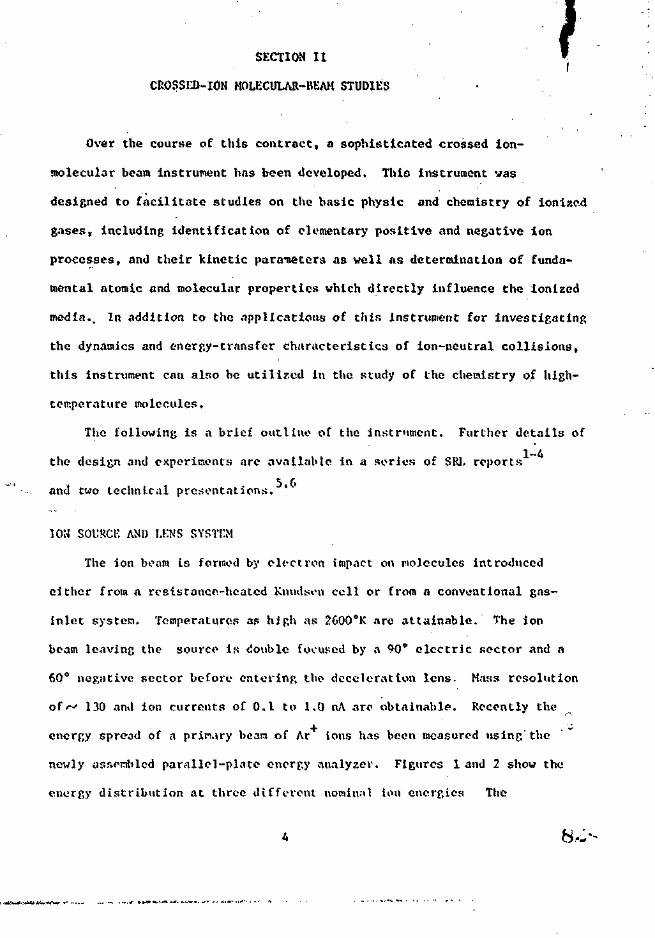
SECTION IIf
CROSSED-ION MOLECULAR-BEAM STUDIES •
Over the course of this contract, a sophisticated crossed ion-
molecular beam instrument has been developed. This instrument was
designed to facilitate studies on the basic physic and chemistry of ionized
gases, including identification of elementary positive and negative ion
processes, and their kinetic parameters as well as determination of funda-
mental atomic and molecular properties which directly influence the ionized
media.. In addition to the applications of this instrument for investigating
the dynamics and energy-transfer characteristics of ion-neutral collisions,
this instrument can also be utilised in the study of the chemistry of high-
temperature molecules.
The following is a brief outline of the instrument. Further details of
1-4the design and experiments are available in a series of SRI. reports
and two technical presentations. *
ION SOURCE AND LKNS SYSTO1
The ion beam is formed by electron impact on molecules introduced
either from a resistance-heated Kmidscu cell or from a conventional gas-
inlet system. Temperatures as high as 2600eK are attainable. The ion
beam leaving the source is double focused by a W electric sector and a
60° negative sector before entering tbo deceleration lens. Mass resolution
of*-' 130 and ion currents of O.I to 1.0 nA are obtainable. Recently the
energy spread of a primary bean of Ar Ions has been measured using the
newly assembled parallel-plate energy analyzer. Figures 1 and 2 show the
energy distribution at three different nominal ion energies The

1.0
0.9
0.8
0.7
to 0.6ZUJ
LJ
0.4UJ<r
0.3
0.2
O.I
I2.0 2.2 2.4 2.6 2.8 3.0 3.2 3.4
Ar+ION ENERGY (eV)
3.6 3.8 4.0
1. Ar Kinetic Energy Distribution, Nominal Energy 2.A and 3.7

1
1.0
0.9
0.8
0.7
t °-6CO
IS 0.5UJ
oc
0.3
0.2. -
0.1 -
010.0 10.2 10.4 10.6 10.8 11.0
Ar+ION ENERGY (eV)
Fip.uro 2. Ar+ K i n o t i i 1 KiU'r,",y His t r i h n t ion, Nonln.'il Energy 10.5 <-V
84--

distributions vary with energy; however, the full-width-half-maximum vafws
do not exceed 0.3 eV at energies above 1 cV. A kinetic energy range of
1 to 170 eV is accessible with trausraission-to-collision region above
90% down to 1 eV. Transmission to the second-stage detector is considerably
less than this at low energies due to space-charge effects and angular
divergence.*
NEUTRAL-BEAM SOURCE
The mass and energy resolved beam is crossed at 90° by a molecular beam
produced by a stainless steel multichannel capillary array. The beam is
chopped for phase-sensitive detection.
PRODUCT-ION DETECTION SYSTEM
The main scattering chamber is stairiles* steel, 36 in. in diameter
and 15 in. high, pumped by high-speed 10- and 6-in. oil diffusion pumps.
The product ions from the scattering process enter a parallel-plate
energy ananlzer, quadrupo.le mass spectrometer, and a Bendix Channeltron' ' i
operated in the pulse-countinp, mode. The entire detection system rotates
in the horizontal plane about the scattering center, and product ions
are collected over the region -5° to + 95° with respect to the incident-
Jon beam direction.
faii-

SECTION III
DEVELOPMENT AND APPLICATION OF ANALYTICAL METHODOLOGY FORDETAILED CHARACTERIZATION OF AIR FORCE HtfR&ICIDE ORANGE STOCKS
INTRODUCTION
In sup>ort of the U.S. Air Force for determining the feasibility of
the soil-biodegradation method of disposal of excess Air Force herbicides
in accordance with Environmental Protection Agency guidelines, personnel
of Systems Research Laboratories, Inc., were requested to develop and apply
analytical gas chromatograph-mass spcctrometric \GC-MS) methods in the
quantitative determination of Herbicide Orange and degradation products
thereof in soil and milk and to establish the composition of representative
samples of Herbicide Orange formulations.
This work under Contract No. F33615-73-C-4099 was undertaken in 1972
and continued through June 1975. The research was performed in conjunction
with U.S. Air Force personnel at the Aerospace Research Laboratories,
Wright-Patterson Air Force Base, Ohio, and in cooperation witli personnel
in the Department of Life and liehnvioral Sciences, U.S. Air Force Academy,
Colorado Springs, Colorado, who supplied samples of soil from various
field-test plots.
Several analytical techniques were developed during the contract
period for analyzing Air Force Herbicide Orange. As a result, each mission
was accomplished within a different period of time and results reported to
the Air Force Logistics Command. A brief description of each period
follows:
btv-

A. 972 - 1973; A detailed description of the results of this
effort Is available in SRI. Semiannual Status Report 6776-1, Contract
No. F33615-73-C-4099. The work involved:
« . Extraction of the herbicides n-butyl 2,4-0 and 2,4,5-T
and related compounds by means of an organic solvent
from soil samples.
2. Treatment of the extract to convert the 2,4-D and 2,4,5-T
to a derivative (methyl esters) amenable to gas-
chromatographic analysis.
3. Analysis of the extract using GC-MS.
4. Mass-spectral characterization of selected Herbicide
Orange formulations.
B. 1973 ^ 19M: Sp-L Arus'ial Status Report 6776-2, Contract No.. ^
F33615-73-C-4099. Progress was made in the following areas:
1. Development of software for the data acquisition and
control system used with tho I.oenco 160 gas
chronatograph-Dul'ont 21-491 mass spectrometer system.
2. Development of improved gas-chroma tographic methods
for separation and identification of components of
Herbicide Orange formulations.
3. Development and implementation of analytical methods
for determining 2,3,7,8-Tetrachlorodibenzo-p-dioxin
(2,3,7,8-TC»r>).

c" 1974 - 1975; Progress during this period is described in detajj.
in SRL Semiannual Status Report 6776-3, Contract No. F33615-73-C-4099. 9
Two progress reports have been submitted to the Air Force Logistics
Command. * The work involved:
1. Completion of software for the data-acquisition and
control system used with the ARL gas chroma top.raph-
roass spectrometer (GC-MS).
2. Development and application of an analytical technique
for quantitative determination of dichlorophenoxy and
trichlorophenoxyacetic acids in Herbicide Orange.
3. Determination of tetrachlorodibcnzo-p-dioxln in
Herbicide Orange.
"• J-?7._. rLEIS55*"!!? • Description of these results is available In
SRL Annual Status Report 6776-4, Contract No. F33615-73-C-4099. 12
Two Aerospace Research Laboratories technical reports have been
completed. ' One; manuscript' has been submitted for publication
in Analytical Chemistry and is included as part of this section. The
work included:
1. Complete construe t ton of high-sens! tivity gas
chroruit oj;raph-qu.'idrupole and AKI MS-30 double-beam
ma ss- spec t r ome t er sy s t cms .
2. Development of a successful liquid-chromatographic
technique for extraction of 2S3,7,8-TCI)D in Herbicide
Orange.
'j. Complete analysis. of TC.'Di) in 250 fiamplos of Air Force
llorbicido Oram;r.
10

the recent developments are application of CC-MS techniques
for quantitative analysis of 2,3,7,8-TCDD in soil and milk 'and is
described as follows.
DETERMINATION OF 2,3,7,8-TKTRACin.ORODlBENJlO-p-DIOXIN IN MILK
A. Specificity and Selectivity
The gas chromatographic-mass spectrometric (GC-MS) technique is
extremely sensitive and specific for the determination of TCDD. In order
to assign a signal to 2,3,7,8-TCDD, two things must occur simultaneously:
1) the retention time must be correct and 2) it must respond at m/e 320
as tuned on the mass spectrometer.
B. Apparatus
1. Mini-acktor vials
2. 500-ral beiker
3- 8-ml (2-dram) vials (screw top)
4. Dlsposnble transfer pipettes
5. 0.3-ml cone-shaped vials
6. AEI MS-30 mas;; spectrometer coupled to Varian 1400 gas
chromntoj'.raph with all glass membrane separator
C. Reagents and Materials
1. Ethiinol (MCIi pesticide qua l i ty )
2. Hexano (MCIJ, IIX 29. pest icide quality)
3. Ben/.ene (Mall inc ro td t , 10/i3, nnnograde)
/•. SiHca Gel (MCH, SX 1A3-A, 100-120 mesh)
5. A l u m i n a (Fir.lu-r, A-bAO, 80-100 mt^sh)
6. Potass ium hydrox ide
11

7. Sulfuric acid
8. (Column) 1/8-in, x 5 ft stainless steel tubing
9. (Packing) 1.5% OV"10l on Gas Chrom C (HP)
10. TCDD (available for Dow Chemical U.S.A., Midland, Michigan)
11. o-xylene (MCB)
D. Sample Preparation
1. Put 1 g milk and 1.0 ml 202 KOH in ethanol solution in a
raini-acktor and drop in a 500-ml beaker of boiling ILO for 5 min.
2. Remove and transfer contents to an 8-ml vial.
3. Rinse mini-acktor with 2-ml hexane and add this to the vial.
4. Shake well and allow the layers to separate.
5. With a transfer pipette, remove upper (hexane) layer and
put this into another 8-ml vial.
6. To the vial containing the original reaction mixture, add
another 2-ral mini-acktor rinse and again shake well.
7. Remove upper layer once again and add to original hexane
extract.
8. Wash hexane extract with 2-ml (]N) KOH then with 2-ml
concentrate lUSO^ and 2-ml 10? aqueous Na^CO-.
9. Kvaporato extract to - 1 ml under a stream of air and add
to alumina-silica gel combln;vtion column (see Fig. 3 for construction)
10. Discard first 5-ml of eluate ; collect next 6-ral and
concentrate to * 0.3 ml in a Teflon be:»ker under a stream of air.
12

IQmm-OD STANDARD-WALL BORDSILICATEGLASS TUBING 27cm.LONG WITH A 5cm.TAPERED TIP >
^ALUMINA 9.5cm
; SILICA GEL 10.5cm
'GLASS WOOL
Fifn i ro 1. A l u n l i n - S i l i c a (Io) Conbin.it ton Column

11. Transfer extract to a 0,3-ml cone-shaped vidl, evaporate just
to dryness, and immediately cap with a rubber-lined cap.
12. Just before analysis,, add 50 yl o-xylene to cone-shaped
vial and analyze.
E. Instrument Conditions and Setup
An AEI MS-30 double-beam mass spectrometer coupled with a Varian
1400 series gas chromatograph wan employed and set up according to
the following conditions:
1,, , Column temperature - 230°C
2. Injector temperature - 280°C
3. Separator temperature - 200°C
4. Flow rate 55 cc/min helium at 60 psig
5. Filamenjt current on number 3
6. Magnet tuned to monitor m/e 320
7. Strip chart recorder set 100 rav atten.- at l-in./min
Accelerating voltapt; - 4 kV
Ionizing voltage 70 cV
F. Calibration
1. Inject 2 ul of TCDD standard into gas chromatoyraph; and as the
TCDU elutcii as iilspl.iyed on iho strip-chart recorder, fine tune the
magnet to maxlmtzo the response at m/e 320.
2. Inject 2 ul of a dilute TCOD standard solution of known
concentration .In the f.as chromatoc.rapli and record the response on the
strip-chart recorder.
3. Repeat Stop No. 2 until roproducihi1Ity of detector response
is satisfactory.

' C. • • Analytical Procedure
1* Inject 2 ul of the final extract into the gas chrdmatograph and* ' • •
record the response at proper TCDD retention time and o/e signal*
2. Repeat calibration at least after every two samples.
H. Calculation
1. Calculations are performed by comparing peak height of a
standard of known concentration of TCDD to that of sample to obtain
sample concentration in this case in J.O g of milk.
2j Calculate percent recovery as determined by analysis of a
doped sample.
I. Interferences
Interferences encountered utilizing this technique are somewhat
greater than encountered in much more tine consuming methods but with
the use of a high-resolution instrument such a;; the AEI MS-3Q. These
interferences could be eliminated at the expense of sensitivity.
J. Discussion
The mot hod described here is at present still In the developmental
stage. Interferences encountered near the TCi)D retention tlnv Indicate.
the need for further extract cleanup nioJH icat Jon. 'However, this method
does display -great- promise a:: it can be performed in about half the tltie
of -previously developed methods (see Figs. '» and 5 ).
DKTKKM1 NATION 01- 2 , J,7 ,8-TKTK/\CHI.OR«>DI BKNXO-p-DIOXl N IN SOIL
A. Apparatus
1 Ground ulass stoppered Krlenim-yor flasks (50 ml)
2. 20-ril scrow-capprd tubes
1!)

!0/i! INJECTION OF EXTRACT OBTAINED
•WITH BAUGFiu'AN- MESELSON TREATMENT
(RECORDER ATTN» ICOmv) •
A, CxitMct - Dow Method Cleanup

i
TCDDRETENTION TIME
I
-*J TIME 225sec 0
\0fj.\ INJECTION OF MILK EXTRACT-METHOD UNDER DEVELOPMENT
Figure 5. Extract - Milk Extraction Method Cleanup
• XVL».' *4 »

s *>
3. Laboratory shaker
A. Disposable transfer pipettes
5. 0.3-ml cone-shaped vials
6. AEI MS-3Q mass spectrometet coupled to Varian lAOO gas chromatograph
and all-glass membrane separator
7. Aluminum foi'
B. Reagents and Materials
1. Hexane (MCB» HX 297, pesticide quality)
2. Benzene (Mallincrodt, 10A3, nanograde)
3. (G.C. Column) 1/8-ln. X 5 ft stainless stceL tubing
4. (Packing) 1.5% OV-101 on Gas Ch.-om G (HP) 100/120 mesh
5- TCDD (available Dow Chemical U.S.A., Midland, Michigan)
6. o-xylene (MCB)
r»' • • - .-, . ,',
C. Sample Preparation
Samples to be analyzed were packed in individual sample containers
and kept frozen until time of analysis.
1. Remove sample containers from freezer compartment and allow
to thaw (-2 hr).
2. Weigh out - 20 ?, of soil from each container and allow to
air dry to a constant weight on aluminum foil (shiny side out).
3. Place 10 g of each sample In an ultra-clean Erlenmeyer
flask.
A. Add 15 ml 202 benzene in hcxnr.e to each flask.
5. Put flasks on laboratory shaker and shake for 2 hr.
18

6. Decant the solvent Into a 20-ml screw cap tube.
7. , Rinse soil with 5 r.l 2o% bemene in hcxane,
8. Add rinse to original extract and concentrate down to about
0.3 ml under a stream of air.
9. Transfer extract to a 0.3-ml cone-shaped vial and evaporate
just to dryness and immediately cap with a rubber-lined cap.
10. Just before analysis add 50 jil o-xylene and then analyze.
D. Instrument Conditions and Setup
An AEI MS-3Q double-beam mr.ss spectrometer coupled with a Varian 1400
Series gas chromatograph and an all-glass membrane separator was utilized
in the analyses and set up according to the following conditions.
1. Column temperature - 230°C
2. Injector temperature - 280°C
3. Separator temperature - 200°C
4. Flow rate 55 cc/min at 60 psig
5. Strip chart recorder set 100 mV attenuation at 1 in./min
Ionizing voltage - 70 eV
Accelerating voltage - 4 kV
6. Filament current or. number 3
7. Magnet tuned to monitor m/e 320 "
E. Calibration
1. Inject 2 pi of TCDD standard into gas chromatograph; and as the
TCDD elutes as displayed on the strip-chart recorder, fine tune .the
magnet to maximize the response at m/e
19 97<

2 , Inject 2 pi of a dilute TCDD standard solution of known
concentration in the gas chromatograph and record the response 01: tlio
strip-chart recorder.
3. Repeat Step No. 2 until roproducibility of detector response
is satisfactory.
F. Analytical Procedure
1. Inject 2 yl of the final extract into the gas chroraatograph and
record the response at proper TCDD retention time and m/e signal.
2. Repeat calibration at least after every two samples,
G. Calculations
1. Calculations arc performed by comparing peak height of a
standard of known concentration of TCDD to that of sample to obtain
sample concentration in this case in 20 g of soil.
2. Calculate percent recovery as determined by analysis of a
doped sample.
II. Interferences
1. Interferences resulting from materials having retention times
similar to TCDD and response at m/c 320 may be encountered, especially
if the particular sample contains large amounts of organic material.
2. Glassware and syringes used in the analysis of samples
containing parts-p*>r-bilHon levels of TCDI) may retain sufficient TCDD
to give high n.-sults at parts-pcr-trillion levels.

. . 14*.
I» Discussion *< ' V'"'•
The shake-extraction method described here has been found to be
the least complicated and time-consuming method of alj /esoarched.
Under ideal conditions (i.e., limited organic materials present *n the
soil), interferences were minimal and recoveries rferc on the order
of about 90% at the parts-per-trillion level. The following report
illustrates the usefulness of this shake-extraction method in the recent
analysis of 2,3,7,8- Tctrachlorodibenzo-p-dioxin (TCdD) In soil samples
from Eglin Air Force Base Test Range.
J.t
21

ANALYSIS OF 2,3,7,8 TETRACHLORODIBENZO-p-DIOXIN (TCDD) INSOIl, SAMPLES FROM EGLIN AIR FORCE BASE TEST RANGE
M. L. Taylor and T. 0, Tiernan
Aerospace Research Laboratories (LJ)Wright Patterson Air Force Base, Ohio 45433
R. 0. Yelton
Systems Research Laboratories, Inc.2800 Indian Ripple RoadDayton, Ohio 45440
INTRODUCTION.
Soil samples containing trace quantities of 2,3,7,8 tetrachloro-
dibenzo-p-dioxin were received from Eglin Air Force Base, Florida, packed
in dry ice and were immediately transferred to the freezer compartment of>
the laboratory refrigeration units. It should be noted that samples '
designated as numbers 89 and 90 had been broken in shipment. This
breakage may have;resulted from the unusually high moisture content of <: -•*•-"
these samples which, upon freezing, resulted in expansion and sample 't
container rupture; {.j
ANALYTICAL PROCEDUREi
Soil samples, were prepared for extraction and'analysis by removing
the sample containers from the freezer compartment and allowing them to
thaw. Approximately 20 g of so5.1 were removed from each container and ij
allowed to air-dry on aluminum foil to a constant weight. After drying, s
10 g of each sample were accurately weighed out and placed in an ultra- '<}
clean vessel for extraction. !
ico-

A 4-hr extraction procedure was carried out on each sample utilizing
20% benzene in hexane (both pesticide quality), as the extracting
solvent. The extracts obtained as a result of this operation were
concentrated by a factor of 1000 and subjected to a column chromatography
clean-up procedure using silica gel-alumina columns. Aliquots were -then
analyzed on Varian 144010 GL chromatograph, coupled to an AEI scientific
apparatus MS-30 double beam mass spectrometer through an all-glass membrane
separator. This instrument is capable of detecting low levels of 2,3,7,8
tetrachlorodibenzo-p-dioxin at a mass resolution as high as 10,000. The
m/e 320 peak was monitored continuously and the response wa;.: integrated
as the TCDD eluted from the chromatograph. The integrated TCDD response
from unknowns was compared with the response for accurately known amounts
of TCDD standard introduced into the instrument. Multiple analyses were
accomplished for several samples at different mass resolutions to ensure
that interferences were not a complication.
/RESULTS
The results of these analyses are presented in Table I. Duplicate
analyses for Sample 108 were in rather poor agreement. This may be due
to the fact that this sample apparently contained a large amount of
organic material in the soil which affects the extraction of TCDD from
the matrix. In general, the analyses reflect a standard deviation of
+ 30%. A total of about 300 manhours were spent in the extraction,
preparation, and evaluation of the Eglin ooil sample data.
23

TABLE I
TETRACliLORODIBEN'/.0~p-DIOXIN LEVELS IN SOIL SAMPLES FROMEGLIN AIR FORCE BASE, FLORIDA
SampleNumber
85
85
86
86
87
88
89
90
91
91
92
106
106
107
107
1C7
108
108
109
109
119
119
120
120
Mass SpectrometerResolution
1000
10000
1000
10000
1000
1000
Broken in Shipment
Broken in Shipment
1000
1000
1000
1000
1000
1000
1000
1000
1000
1000
1000
1000
3000
1000
3000
TCDDConcentration
1549 ppt
1241 4424 ppt
1237 ppt
1261 +431 ppt
262 ppt
293 ppt
121 ppt
106 ppt
173 ppt
138 ppt
231 ppt
175 ppt
247 ppt
261 ppt
418 ppt
300 ppt
309 ppt
611 ppt
514 ppt
414 ppt
353 ppt
24

Rapid Technique for Quantifying
tTotrachlorodibenzQ-p-Dioxin
Present in Chlorophenoxy
Herbicide Formulations
by
B. M. Hughes, C. D. Miller, H. L. Taylor, R. L. C. Wu1
C. E. Hill, Jr.1 and T. 0. Ticrnan2
Chemistry Research LaboratoryAerospace Research Laboratories (AFSC)
Wright Pactcrfion Air Force BaseOhio 45433
Systems Research Laboratories, Dayton, Ohio 45440
2Author to whom reprint requests and correspondence should beaddressed.

BRIEF
An improved column-chromatography procedure has been developed for use
with a unique, automated gas chromatograph'-quadrupole mass spectrometer
system to determine 2,3,7,8-tctrac*ilorodibenfco~p-dioxtn concentrations as
~&low as 10 g/g sample, with a relative standard deviation of about 6%.
104-

ABSTRACT - '
An Improved column-chromatography procedure is described for efficient
extraction of 2,3,7,8-tetrachlorodibenzo-p-dioxin (TCDD) from r.hlorbphenoxy
hevblcide matrices. This procedure is rapid, docs not require concentration
of rtluate prior to analysis, and minimizes sample and glassware handling,
thus reducing toxicxty hazards. A highly stable, automated gas chrooatograph-
quadrupolc nutss spectrometer (CC-QMS) system has been developed for
quantifying TCDD in the lolumn-chromatogrr.phy eluate at levels as low as
•-ft10 g/g sample. The relative standard deviation is 6.3Z for the overall
procedure, 'i'he CC-QMS system permits direct introduction of the GC effluent
at flow rates of up to 30 ml/min into the MS ion source and is equipped with
pneumatically operated valves for automated venting of components which are
not of interest. The GC-QMS is equipped with an automatic sample injector
8'" a data acquir.itiyn and control system wiii'-h allows continuous unattended
operation for periods up to 24 hours. • •• ~ .
its

The chemistry and toxicology of chlorinated derivatives of dlbcnzo-/i 2)
.p-4ioxin (I) are summar'red in two recent publications. '... . • '*, . .'<! ...'.:'
8 H- H 2
H 3
4.CDBlair indicates that theoretically there arc 75 possible chlorod/oxins;
after having investigated the toxicology of several chlorodioxins, Sch^etz
concludes that 2,3,7,8-tctrachlorodihen2o-p-dioxin (2,3,7,8-TCLD) has "an
unusually high"'toxic!ty"." KVsed on laboratory animal studies, 2,3,7,8-TCDD
has been found by Schwetz ' and others to be erobryotoxic, acnegenic,
and lethal (in guinea pigs) after a single oral ''?£" r-tnounting to 0.6 jig
of 2,3,7,8-TCDD per kilogram of body weight. Kimbrough in a review
of the toxicology of 2,3,7,8-TCDD and related materials indicates that the
physiological effects of this material in both animals and humans arc quite
detrimental; instances of illness among industrial workers in plants
manufacturing trichJorphenol have been reported. It has been
established * ' ' that during the synthesis of trichlorophenol,
N *involving alkaline hydrolysis of tctrachlorobcnxenp, 2,3,7,8-TCDD is formed.
Subsequent use of contaminated trichlorophcnol for synthesis of more complex
(3,4)

Qrfj«VQc.tolorine compounds may lead to f,ina products contaminated with
(1.2)3Wr,8~TCDD, Indeed, Moore ' indicate; that chlorinated dibenzodioxins
or dlbenzofurans have now been found as contaminants in fungicides
(pentachlorophenol), herbicides (2,4,5-trichlbrophehbxyacetIc acid), and
polyehlorinated biphenyls. Interest concerning the possible effects 'of» . j
dioxin-contamLnated 2,4,5*-T was aroused by the work of Courtney ' which
precipitated Congressional hearings and, subsequently, action by the
(13)U.S. Environmental Protection Agency.
Continuing concern about 2,3,7,8-100 ' ' has prompted attempts to
determine its prevalance in a wide variety of substances including
,, (16,17,18) , . . , , (18,19,20,21,22) , , . , .soil, ' animal and plant tissue, and various cheraical
matrices — especially pesticides and herbicides. * ' Certain of
the techniques reported for assaying environmental and biological samples
for 2,3,7,8-TCDD content; are purported to be quite sensitive, permitting
-12quantitative analysis of concentrations as low as 10 g of 2,3,7,8-TCDD
per gram of sample. However, methods for analysing chemical products such
as herbicide formulations need not be ultra sensitive, because herbicid'es
are greatly diluted prior to application. Thus, analytical methods which* _ft
are less sensitive (10 g of 2,3,7,8-TCDD per gram of sample) are sufficient
for analysis of undiluted herbicides. In addition to the sensitivity of
the analytical method, however, th<?te is the need for specificity to permit
unequivocal identification of the 2,3,7,8-TCDD. Many chlorinated herbicides
and pesticides have chemical and physical properties which are similar to
those of 2,3,7,8-TCDD, and these compounds may interfere with the
quantitative determination of the latter. For example, polychlorinated
107-

biphenyls and ODE (arising from dehydrohalogenation of PDT) have been
implicated as interferences in certain methods. ' Of those analytical
methods currently available, coupled gas chromatography-mass spectrotnctry
(GC-MS) affords the most powerful combinntion of specificity and sensitivity,
(19 23—31^and several of the methods cited previously * make use of GC-MS
instrumentation. »-:
In this laboratory r. method for determining 2,3,7,8-TCDfc in a large
number of chlorophenoxy-type herbicide samples was sought. Implementation
of methods reported in the literature > » ~ / prove(j impractical because
these methods either lacked specificity or required time-consuming,
inherently irreproducible procedures which rendered them useless for large
numbers of determinations. The aim of the present study was to develop a
method which would eliminate these procedures — particularly concentration
steps, sample transfers, and rigorous glassware cleaning. A greatly improved
method for determining 2,3,7,8-TCDD in chlorophenoxy herbicides is reported
here; a simple and rapid sample-preparation sequence accomplished with
completely disposable glassware and small volumes of herbicide and solvents
minimizes handling -- thereby reducing toxicity hazards -- and eliminates
the concentration of sanple extracts. The sample preparation is followed
by direct analysis of the extract using GC-MS. The 'instrument described here
is a fully automated gas chromatograph-quadrupole mass spectrometer (GC-QMS)
system developed in this laborarory; the quadrupole mass filter is capable
of sequential monitoring of as many as six masses and unattended
operation lor periods up to 24 hours. With this proccdvire, TCDD detection
—8sensitivities of 2 x 10 g of 2,3,7,8-TCDD per gram of sample are achievab
routinely, and large nunbers of samples can be analyzed rapidly.

EXPERIMENTAL
• . . . . .
Stajrdards and Jtea cnts. The benzene (Nanogradc) used in this study
was obtained frosj Mallinckrodt, and the hcxane (Pesticidequaiity) was
obtained from Matheson, Coleman, and Bell. Alumina (Fisher Scientific, A 540,
80-200 roesh) was conditioned at 120°C for at least 12 hr and maintained at
that temperature until immediately prior to use. Silica gel (Matheson,
Coleman and Bell, GC grade, 100-200 tnesh) was used as received. The
2,3,7,8-tetrachlorodibenzo-p-dioxin used to prepare calibration standards
was obtained frosa Dow Chemical Co., Midland, Michigan, and was certified
to be 98.6% pure, bas<-u on raasa-spectrnl analysis. The mass spectrum
of the Dow 2,3,7,8-TCDD sample was also determined in this laboratory and
compared with that of a sample of 1,2,3,4-TCDD obtained from Analabs, Inc.
The results support the Dow purity estimates.
Column-Chroaatography Procedure. The following sample pretreatment
or clean-up procedure was developed for removing compounds which interfere •
with the GC-MS determination of 2,3,7,8-TCDD:
1. Prepare a 30-cn glass column using 10 ram o.d., standard-
wall Pyrcx tubing (one end of glass tube is pulled down
to 2 mm o.d.).
2. Instrt a plug of silanlzed glass wool .into the column; add
4 g of silica gel followed by 4 g of alumina.
3. Moisten column with 20% benzene in hexane.
A. Dilute 1 g of herbicide with 0.5 ml of 20% benzene in hexane,
and transfer this solution to the moistened column. Wash the
vessel with an additional 0.3 ml of solvent, and add the wash to
the top of the column. ^ '"<!«-
5
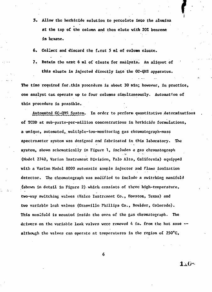
f5. Allow the herbicide solution to percolate into the alumina
at the top of the column and then elute with 20% benzene
in hexane.
6. Collect and discard the fjXst 5 ml of column cluate.
7. Retain the next 6 ml of cluate for analysis. An aliquot of
this eluate is injected directly into the GC-QMS apparatus.
The time required for -this procedure is about 30 min; however, in practice,
one analyst can operate up to four columns simultaneously. Automation of
this procedure is possible.
Automated GC-QMS System. In order to perform quantitative determinations
of TCDD at sub-parts-per-milllon concentrations in herbicide formulations,
a unique, automated, roultiplc-ion-monitorlng gas chromatograph-mass
spectrometer system was designed nnd fabricated in this laboratory. The
system, shown schematically in Figure I, includes a gas chrotaatograph. jj - • j .
(Model 2740, Varian Instrument Division, Palo Alto, California) equipped
with a Varian Model 8QOO automatic sample injector and flame ionization
detector. The chromatograph was modified to include a switching manifold
(shown in detail in Figure 2) which consists of three high-temperature,
two-way switching valves (Valco Instrument Co., Houston, Texas) and
two variable leak valves (Granvillo Phillips Co., Boulder, Colorado).
Thiis manifold is mounted inside the oven of the s«is chromatograph,, The
driwrff on the variable leak valves were removed 4 in. from the hot zone —
although the valves can operate at temperatures in the region of 250°C,

the drivers can operate only to 75*C (engineering drawings for modifying
these valves were supplied by the Granville-Phlllips Co.). The tubing* • •
used in the. manifold and throughout the heated portions of the system is
l/8-in.~o.d. stainless steel lined with glass (available from Alltech
Associates, Arlington Heights, Illinois). Switching Valve No. 1 (see
Figure 2) is equipped with a solenoid-actuated pneumatic operator whinh
permits automated venting of the solvent (or other components which are not
of interest). When the helium effluent from the chromatographic column is
being vented, helium from an auxiliary line continues to enter the mass-
spectrometer ion source. The needle valve in the vent line and the pressure
regulator in the make-up helium line permit appropriate adjustment of flows
and pressures; therefore, when Switching Valve No. 1 is in either "solvent
vent" or "normal flow" position, identical pneumatic conditions prevail and
mass-spectrometer ion-source conditions arc unperturbed which prevents large
shifts in the base-line signal output from the mass spectrometer and permits
smooth instrument operation even during repetitive switching of Valve No. 1.
Switching Valves Nos. 2 and 3 are interconnected by means of a loop which
includes a Matheson Model ALL-100 linear mass flowmetcr (Matheson Gas
Products, East Rutherford, N.J.) and a pressure gauge (Muthc'&on Model
P/N 63-3103). The gas flow and pressure in the line to the mass spectrometer
or to the flame-ionization detector (FID) can be measured during actual
operation of the instrument, with only slight perturbation in signal
output from either the FID or the mass spectrometer.
The quadrupole mass filter employed is manufactured by Extranuclcar
Laboratories (Pittsburgh, Pennsylvania). The mass filter and source arc
housed in a 6-In. stainless steel "T," and the source and mass-filter regions
111"

i
are separated by means of, a Tcflpn collar which permits differential pumping»
of the two regions, Tlus analyzer region is pumped by a 4-in, Varian-URC
Model 161-2 oil-diffusion pump, and the source envelope is pu...ped by a
6-in, liendix Model PVM-100 diffusion pump. Both pumps are equipped
with gate valves and cryogenic traps. Pumping in the source region is
adequate to permit direct introduction of the gas-chromatograph effluent
at flow rates up to 30 cc/min without the use of a helium separator. Typical• '
pressures in the source envelope during operation are on the order of
-4 -61 x 10 torr, and a pressure of 2 x 10 torr is maintained in the*
analyzer region.
The mass spectrometer in the configuration described has a maximum
mass resolution of 1000; for the studies described herein, however, the mass
resolution was adjusted to about 200 at m/e 320? and a single mass fragment
(m/e 320 or m/e 322) was monitored as a function of time to obtain
quantitative data.*f' ~ . r ... ^ ,,. ,1
To permit automatic data acquisition and control, the GC-QMS system
was equipped with an Autolab System IV Computing Integrator (Spectra-
Physics, Inc., Mountain View, California^, to display the data in digital
form and also to record the data on punched paper tape uning an ASR-33
Teletype. Mass chroroatograms were acquired on a strip-chart recorder.
A HP 2116-C computer was programmed to reduce the data from the punched
paper tape and to compute the dioxin concentration and the percent
standard deviation for each sample injection.
In the fully automated mode, the GC-QMS functions sequentially as
follows:

1. Automatic sample Injector purges syringe, loads sample
e rlnge, makes irjfcfon, and activates integrator.
2» Integrator begins data acquisition and, after & programmable
time delay, activates solenoid vent valve. This valve
automatically switches the GC effluent into the QMS after the
solvent has eluted, allowing all effluent to enter the ion
source.
3. After another programmable time delay, the integrator
closes the solvent vent valve, computes areas, and yields
printed and punched paper tape records of data.
4. After a preselected time interval corresponding to the
duration of the above process, the automatic sampler reactivates
the above cycle.
The time required for a complete instrument cycle under the operating
conditions outlined is about 15 min. The instrument was calibrated using
a 2,3,7,8-TCDD standard as noted previously. In practice, the automatic
sample-injector carrousel was loaded in such a way that one standard
was injected after each three unknown samples. Duplicate injections of
samples and standards were also made. The procedure markedly improved
the precision and accuracy of the data obtained.
Specific operating parameters for the gas chromatograph and mass
spectrometer are as follows:

Gas Chromatograph;
Column; • 6-ft x l/8 JLn. o.d. glass coiled column
packed with 10% OV-17 on Chromosorb W/HP
Carrier Gas: Helium nt 30 cc/min
Temperatures: Injection Port - 240*C
Column - 230°C
FID detector - 240*C
Transfer line into mass spectrometer - 310°C
Mass Spectrometer:
Ionizing Voltage: 23 eV
Multiplier Voltage: 3500 V
Envelope Pressure: 2.3 x 10 torr
Analyzer Pressure: 3.5 x 10 torr
- To corroborate data obtained with ...the GC-QMS, a double beam MS-30
mass spectrometer AE1 Scientific Apparatus, Ltd. (Manchester, England)
coupled through a silicone membrane separator (AEI Model WI'029) to a
Varian 1440 gas chromatograph was employed. The operating parameters for
this system are as follows:
Gas Chromatograph:
Column: 5-ft x 1/8-in. o.d. stainless steel packed with
1.5% OV-101 on Chromosorb G/HP (100/120 mesh)
Carrier Gas: Helium at 55 cc/min
Temperatures: Injection Port - 260*"C
Column - 262°C
10

*
M'asa Spectrometer;
Resolution: ' 2000
Ionizing Voltage: 70 cV
Source Temperature: 250*C
Separator Temperature: 183*C
RESULTS AND DISCUSSION
Preliminary experiments with typical herbicide formulations demonstrated
that successful implementation of a specific-ion-monitoring GC-QMS technique
for determination of 2,3,7,8-TCDD would require a sample pretreattnent or
clean-up proceduris. Nominal separation of the primary ester components of the
herbicide matrix from the 2,3,7,8-TCDD can be accomplished by gas chromatography;
however, since the ester components elute from the column prior to TCDD and
are present in much larger quantities (by a factor of 10 ), they do in fact,..,., . ... . • :t. ,. , t ,. . _
interfere with the TCDD analysis due to tailing of the main component peaks.
It is therefore desirable to remove the bulk of the esters prior to
injection of the sample into the GC-QMS. Moreover, many of the herbicide
samples were observed to contain other high-molecular-weight compounds!•• -• • - 7 i !>••
which elute from the gas-chromatographic column long after the TCDD. Ifo . ,,.,
sample analysis time is to be minimized, these components must also be removed
prior to injection into the GC-QMS. Otherwise, the peaks arising from these
compounds interfere with the TCDD peaks originating from subsequent sample
injections. Attempts to measure the TCDD by direct injection of herbicide
samples into the mass-spectrometer ion source were also unsuccessful;
in an attempt to detect the very low levels of TCDD present, a ver; large
11 JU5-

volume of herMcide was, introduced f« too large for the available pumping
capacity of the system •*«•« and the resulting ion-source pressures were
excessive.
In initial efforts to isolate 2,3,7,8-TCDD from chlorophenoxy herbicidef\Q)
matrices a previously reported liquid chroratography method was used.
This procedure involves dissolving 5 g of sample in 25 mi of solvent (20%
benzene in hexane) and introducing this solution onto a column containing
50 g of silica gel equilibrated with the solvent. This procedure requires
about 2 hr and yields the TCDD in 100 ml of solvent. A concentration step
oust be performed before the sample is injected into the GC-QMS. A
(19)simple solvent evaporation step used in the procedure described earlier
is difficult to accomplish in a reproducible manner and can lead to TCDD
losses. Also, all glassware and vessels used for a given sample must be
cleaned with extreme rigor to avoid carryover of TCDD in subsequent
analyses. Since these steps arc time consuming, a shorter and more
efficient procedure was sought which would minimize the volume of solvent
needed in the liquld-dhromatographic sequence and would permit the use
of disposable columns and containers.
(22 23)Since alumina has been mentioned in the literature " as a useful
medium for isolation of TCDD from certain samples, its utility in separating
TCDD from the chlorophenoxy matrix was examined. Liquid-chroma tography
columns of varying dimensions were prepared if. ing alumina and alumina-
silica gel combinations, and the efficacy of these columns was determ'tied.
Standard solutions of TCDD* as well as chlorophenoxy herbicide samples
doped with known amounts of TCDD, ware chromatographed using the various
columns, and aliquots of the cluatc were collected and analyzed for TCDD
12

using ttoe SC-QMS apparatus described earlier. Plotted in Figure 3 arc
typical data which illustrate the distribution of TCDD in the cluatc froa
a column prepared using 10 g cnch of silica gel and aluminc1 in a 10-mm-o.d. x
30-cra-long glass tube. The 2,3,7,8-TCDD is seen to elute entirely in
6 ml of the solvent. Attempts io collect only the "center fraction" of the
6-ml aliquot led to irreproducible results. Apparently, variations vhith
occur in the preparation of the columns cause the elution pattern of• ' ' i
2,3,7,8-TCDD to vary somewhat from column to column; never theless, analyses
based upon collection of the entire 6-ml aliquot of cluatc are observed to
be quite consistent. Mass chroma tograms (instrument tuned to monitor m/e 320)
of a chlorophenoxy herbicide extract obtained using the silica gel-alumina
column are shown in Figure A . Most of the interfering compounds have been
effectively removed, and the TCDD peak is clearly resolved from those of
the remaining compounds which also exhibit ra/e 320.
Further studies were conducted to assess the precision and accuracy
of the analytical data for TCDH obtained by means of the clean-up technique
described above. In these experiments accurately doped chlorophenoxy
herbicide samples were analyzed as well as samples of herbicides known to
Contain 2,3,7,8-TCDD as a contaminant. Table 1 shows the measured concen-
tration of 2,3,7,8-TCDD in an extract of an actual field sample of a>• , .. . . /
chlorophenoxy herbicide which was determined fay making six sequential
injections of the same extract into the GC-QMS. These results are indicative
efi the precision of the GC-MS measurement, and the relative standard
deviation is seen to be 1.8%. In Table II the results for five different
1-g aliquots of another herbicide specimen are presented. Each of the
samples was subjected to the clean-up procedure, and the resulting extracts
13

vere analyzed using the CC-rMS, These data indicate that the reproducibility
of the overall analytical process ie +6.3%.
In Table III the levels of TCDD observed in respective sub-fractions
of the 6 ml of liquld-chromatography column eluate are shown for a series
of replicate herbicide samples (both doped and containing only "native"
TCDD). While the level of TCDD in a given sub-fraction varied markedly'
within the set, it should be noted that the analyses of replicate samples
based on ,£he total TCDD in the entire 6 nil of eluate ->re in excellent
agreement.l
It is evident from the data shown in Figure 4 that even after
application of the sample clean-up procedure described above, several
herbicide components which exhibit a mass spectral peak at m/e 320 remain.
These components are usually resolved by the gas-chromatographic column,
and the peak corresponding to TCDD can be determined by comparing the retention
times of the unknown peaks with that obtained for a TCDD standard. To
verify that the peak identified as TCDD includes no other components (having
identical gas-chromatographic retention times) several isotopic peaks in
the mass spectrum may be monitored simultaneously and the ratios of these
compared with the corresponding ratio for a TCDD standard and with the
theoretically predicted ratios of chlorine isotopes. Such a comparison is
shown in Table IV for the ratio of the m/e 320 to tn/c 322 peaks [molecular
ion and (molecular ion + 2) isotopic peaks]. The expected peak ratios are
observed for the unknowns, confirming that the monitored component is
indeed TCDD.
14

further verification of the accuracy of the results obtained with
the described procedure", the extracts from several samples were also
analyzed using an MS-30 double-beam mass spectrometer coupled to a Varlan 1400
gas chromatograph. Single-ion monitoring was again employed, and the experi-
mental conditions were similar to those described Cor the automated GC-QMSi
apparatus described earlier. With the MS-30 Instrument, however, a
different gas-chromatographic column packing was utilized — 1.5% OV-101
on Chroraosorb G, With the MS-30 tuned to m/c 320 and the resolution adjusted
to 2000, the data reported iit Table V were obtained for a aeries of samples.
For comparison, the corresponding results obtained using the quadrupole
Instrument are also presented in this table. The data are seen to be in
reasonably good agreement.
Other herbicide formulations consisting of octyl end ir.ooctyl csterr.
of various chlorophenoxyacetic acids were randomly selected for analysis
using the described methodology. No difficulties were encountered, and
these results Indicate thwt 2,3,7,8-TCDI) can be quantified in a wide
variety of commercial herbicide formulations using the analytical methodology
described here.
CONCLUSIONS
An analytical method has been reported for rapid determination of
••82,3,7,8-TCDD at concentrations as low as 10 g/g sample in a variety of
sample matrices, Including the butyl esters of dichloro -and trichloro-
phenoxyaicetic acids. Commercially available herbicides — consisting of
solutions of octyl esters of 2,4-1) and/or 2,/i,5-T In concentrations ranging
15

from 7 to 65% •— have also been assayed for 2,3,7,8 'fCDD content without
difficulty. The automated CCrQMS system developed Cor these applications
is highly sensitive -~ yet extremely stable ~~ and thereby lends itself to
unattended, automated operation for long periods. Such instrumentation is
undoubtedly the key to eost-eftec'tive quality-control programs in which
statistically valid sampling techniques are implemented to monitor hazardous
components.
These studies were supported in part by the U.S. Air Force Logistics Command.
16

REFERENCES
1. "Chlorodioxins — Origin and Fate," E. H. Blair, Ed., Advances in
Chemistry Series No. 120, American Chemical Society, Washington, D. C.
1973.
2. Environmental Health Perspectives, Experimental Issue No. 5, G. W. Lucier,
' Ed., DHEW Publication No. (NIH) 74-218, U.S. Department of Health,
Education, and Welfare, Public Health Service, National Institutes of
Health, September 1973.
3. B. A. Schweta, J. M. Morris, G. L. Sparschu, V. K. Rowe, P. J. Gehrig,
J. L, Emerson, and C. G. Gerbig, in "Chlorodioxins — Origin and Fate,"
E. H. Blair, Ed., Advances in Chemistry Series No. 120, American
Chemical Society, Washington, D. C. (1973), p. 55.
4. B. A. Schwets, J. M. Norris, G. L. Sparschu, V. K. Rowe, P. J. Gehrig,
J. L, Emerson, and C. G. Geibig, Environmental Health Perspectives,
Experimental ls*ue No. 5, G, W. Lucier, Ed., DHEW Publication No. (NIH)
74-218, U.S. Department of Health, Education, and Welfare,"Public ,;.. , . w .
Health Service, National Institutes of Health, September 1973, p. 87.
5. G. L. Sparschu, F. L. Dunn, and V. K. Rowe, Fd. Cosmet. Toxicol,, £,
4 0 5 (1971). . . . . . . . .,
6. K. D, Courtney and J. A. Moore, Toxicol. and Appl. PhannacQi,, 20,
396 (1971).
7. R. D. Kimbrough, Arch. Path. JM, 125 (1972).
8. G. R. Higginbotham, A. Huang, D. Firestone, J. Verrett, J. Ress, and
A. D. Campbell, Nature, 220, 703 (1968).
9. M. Tomita, Nature, 220, 702 (1968).
17

10. Report on 2,4,5-T. A Report of the Panel on Herbicides of the
President's Science.Advisory Committee, Government Printing. Office,
Washington, D..C., March 1971. •
11. M. H. Milnes, Nature, 232. 395 (1971).
12. J. A. Moore, Environmental Health Perspectives, Experimental Issue
No. 5, G. W. Lucier, Ed., DHEH Publication No. (NIH) 74-218, U.S.
Department of Health, Education, and WElfare, Public Health Service,
National Institutes of Health, September 1973.
13. P. H. Abelson, Science, 170 (1970),
14. D. Shapley, Science, 180. 285 (1973).
15. Anon., Time, September 2, 1974, p. 69.
16. E. A. Woolson, R. F. Thomas, and P. D. J. Ensor, J. Agr. Food Chem.,
20, 351 (1972).
17. P. C. Kearney, E. A. Woolson, and C. P. Ellington, Jr., Environ.
Sci. and Tcchncl., 6., 1017 (1972).
18. W. D. Crunimett and R. 11. Stehl. Private communication.
19. W. D. Crummett and R. H. Stehl, Environmental Health Perspectives,
Experimental Issue No. 5, G. W. Lucier, Ed., DREW Publication No. (NIH)
74-218, U.S. Department of Health, Education, and Welfare, Public
Health Service, National Institutes of Health, September 1973.
20. R. Baughman and M. Meselson, "Chlorodioxins — Origin and Fate,"
E.. H. Blair, Ed., Advances in Chemistry Series No. 120, American
Chemical Society, Washington, D. C., 1973.
18

21. R, Baughman and M. Meselaon, Environmental Health Perspectives,4
Experimental Issue No, 5, G. V, Lucier, Ed., DHEW Publication No..' " • •
CNIH) 74-218, U.S. Department of Health, Education, and Welfare,
Public Health Service, National Institutes of Health, September 1973.
22. D. Firestone, D. F. Flick, J. Ress, and 6. R. Higgenbotham, J. Assoc.
Offic. Anal. Chemists, 54., 1293 (1971).
23. M. L. Pocter and J. A. Burke, J. Assoc. Offic. Anal. Chemists, 54.,
1426 (1970).
24. D. T. Williams and 8. J. Blanchficld, J. Assoc. Offic. Anal, Chemists,
54, 1429 (1971).
25. R. W, Storherr, R. R. Watts, A. M. Gardner, and T. Osgood, J. Assoc.
Offic. Anal. Chemists, 54, 218 (1971).
26. K. S. Brenner, K. Mullet and P. Sattcl, Jf. Chromatog., 64_, 39 (1972).
27. D. Firestone, D. Ress, N. L. Brown, R. P. Barren, and J. N. Danico,
J. Assoc. Offic. Anal. Chemists, J55, 85 (1972).
28. D. T. Williams and B. J. Blanchficld, J. Assoc. Offic. Anal. Chemists,
,55, 93 (1972).
29. D. T. Williams and B. J. Blanchfield, J. Assoc. Offic. Anal. Chemists,
55, 1358 (1972).
30. T. J. N. Webber and D. G. Box, Analyst, $>8, 181 (1973).
19

FIGURE CAPTIONS
Figure 1. Schematic representation of automated GC-QMS system.
Figure 2, Diagram of switching-valve manifold for automated GC-QMS system.
Figure 3. Distribution of tetrachlorodibenzo-p-dioxin In the solvent eluted
from an alumina-silica gel liquid-chromatography column.
Figure 4. Mass chromatograms (monitoring m/e 320) obtained with the
GC-QMS for a TCDD standard (80 ppb in 20% benzene-hexane
solvent) and for two herbicide extracts.
20

Table I, Replicate Analyses of a Single Extract FromAn Unknown Herbicide Sample
US/g FoundAnalysis %.v ' ''
1 0.135
2 0.134
3 0.133
4 0.131
5 0.138
6 OJ.4&
3?« 0.137a
s • 0.0025b
2« « i ft6AS JL« o
X « Aritliraetic mean
s 0 Standard deviation of the mean
c%s =» Relative standard deviation

II, Replicate Analyses (Separate Extractions) ofAn Unknown Herbicide Sample
JMS/C FoundSample No . ' 'T'.'.' (ppm)
1 0.22
2 0.18
3 0.20
4 0.25
'• ' 5 • ' '' • ' " • ' ' ' - • ' • 0'25 •
<s •*••*X * Arithmetic mean
s « Standard deviation of the mean
%s e Relative standard deviation
JUG

Table HI, TCDD Levels in Fractions of the Eluate from LiquidChrotnatographjr Column (Alumina-Silica Gel)
yg TCDD Found0
(ppro)
First 4 ml of eluate
Next 1 ml of eluate
Next 1 til of eluate
Next 1 ml'pf fduate..
Next 4 wl of eluate• * > ' , . • '
Tot'al Found
27J5KP
N.D.
N.D.
0.034
0.240
' : ' ' '%2U;0.59
27 SF 27 SFA.'ffa .*•'.•**-
N.D. N.D;
N.D. N.D.
0.013 0.007
a.058 0.065
M4$ '0411
0.221 0.188
275G
N.D.
N.D.
0.004
0.048
&M
0.10
27SJ1
N.D.
N.D.
0.20
0.32
fiifil
0.59
Samples designated K, E, etc., arc replicate samples from sameherbicide specimen.
Spiked with an additional 0.33-pg TCDD/g.

1 " ' $ • • • ' •Table IV, Observed and Theoretically Predicted
Radios oJt tCDD Isotopic Peaks
80 ppm Std, 0,84, 0,87
275 V 0.86
275 *' 0.78, 0.74
275 G 0.74
275 L 0.80
,' ' "' 0.77 ' " . . ' . . "
Samples designated as V, F, etc. are replicate samples from sameherbicide specimen.

Table V. Compattson of Hlgh^Resolution andtQWrResoliition GOMS Results
,• *'
yg/g Found
AKL.Sample* Gq-QMS ' eOMS-30
436-1 0.07 0,07
436-2 0.07 0.05
. 414-1 0.53 0.31
• 414-2 — °-38
413-1 0.14 0.11
* 413-2 •'•*• 0,11
17 < 0.02 0.01,
Samples designated -1 and -2 are 'duplicate injections of thesame sample extract.

AUTOMATICSAMPLEINJECTOR
(SOLVENT VENT VALVE)
GAS CHROMATOQRAPH
IONIZATION DETECTOR
QUADRUPOLE MASS SPECTROMETER i'
SOURCE ANALYZER
300°C TRANSFERLINE
AUTOLA8
COMPUTING
INTEGRATOR
GC-QMS ELECTRONICS
TTY
cAI*

VENT
MAKE-UPHELIUM
JTTTlGRANVLLE-PHLUPS
LEAK.
PRESSURE1
REGULATOR PRESSUREGAUGE
VALCO H(GH TEMPERATURESV/1TCHING VALVES
MASSFLOWMETER
(—INDICATES DIRECTION OF FLOW)PRESSUREGAUGE
o_G.C. FLAMEIONIZATIONDETECTOR
TO MASS/O\SP£CTROI
GRANV1LLE-PH1LUPSLEAK
H-

12,5 13 13.5 14 14.5 15 15.5 16 16.5 17
TOTAL VOLUME OF COLUMN ELUATE
175 IS 18.5 19 19.5 20

UJCOISoCLCOLUcrLJ
IUJ
TCDDSTANDARD
H-f \t>»-^ \W*<
A
a= EVENT MARKER FOR INJECTIONAND START INTEGRATOR
b= EVENT MARKER FOR STOP INTEGRATORAND PRINT OUT RESULTS
c* GC EFFLUENT OPEN TO MASS SPECTROMETERION SOURCE
d= GC EFFLUENT CLOSED TO MASSSPECTROMETER ION SOURCE
SAMPLE
TODD
TIME

"•*<*.
SPARK-SOURCK AND ELECTRON-IMPACT MAS.S-SPECTROMKTRIC STUDIES
. During this final reporting period, «park-sourco and electron-
impact mass-spectrometrie me: -ods were employed in Air Force Mat-jrlals
Laboratory .(AFML) research programs. These analytical efforts and results
are described herein. Spark-source mass-apoctrograpliic (SSMS) studies
1 A«l ftperformed earlier arc detailed in previous reports.
INTRODUCTION
Specific causes of failure of bearings in the Third Generation Gyro•»
(TGG) to be used in Minute Man III were nought by various nondestructive
analytical mass-spectrometric techniques. The amount and kind of
inorganic contaminants on the surfaces of several "Inner" bearing components
as well as other specimens were determined using spark-source mass
spectrography; the sample-handling procedures and results are giv.'n below.
In add! tier), composition pf .seven gas samples and the outgassing products
from a rejected motor stator were cleteniiitK-d using conventional electron-
impact mass spectromotry, and these results are also discussed here.
SPARK-SOURCE ANALYSIS
Spark-source raass-spectrographic analyses of beryllium bearings,
sublimation products collected on glass slides, stators, and cpoxy were
carried out and the resulting elemental data are shown in Tables II, III,
and IV. These analytical efforts were carried out with the aim of
identifying surface contaminants causing bearing failure.
25

TABLE II
SSMS ANALYSIS 01? BERYLLIUM-BEARING SURFACES*
BearingPesiRnntion
No. 3b
ElementalComp o si tion
Ca, Ti, Cl, Si, Al - Hiph
S, Fe, En, P, B, F, K - Medium
No. 1? Cl, Si -.High
Al, S, Ti, Ca, K, Fe, Zn, P, B, F - Medium
No, 32 Ca, Ti, Si -
Cl, Al, S, Fe - Medium
F, Zn, Li - Low
No. 32 (afterbenzene, he:;aneultrasonic
Ca, Si - High
Cl, Al, S, Fe - Medium
Ti, F, 7.n, B, Li - Low
Cr, Fe - High
a,.Elements listed left to right in approximate order of decreasingabundance.
Relative amounts of observed surface contamination: No.>3 No. 17>No. 32>No. 32 (cleaned).
"No sample designation - subatttcd for analysis in early March of 1975.
26

TABLE III
SSMS ANALYSIS OF DEPOSITS ON MICROSCOPE SLIDES
SlideDesignation
8A*
Elemental
B,S - High
Ti,F - Medium
Zn,Cl - Low
B - High
S,F,Ti,Zn,Cl - Appear to be slightlyabove background
B - High
Zn,Ti,S,F - Medium
Cl - Low
Slide 5>SUde 8A>Slidc 6
27

«*
TABLE IV
SSMS ANALYSIS OF STATORS AND EPOXY
SampleDesignation
Stator 17 a
ElementalComposition
F,Cl,K,Ca,Si,Al,2n,Cu,Fe - High
Li - Medium
Ti,Cr,P,B - Low
Stator 22 Si,Al,B,Cl,Ca,Ba - High
2n»P,Fe,Cr,Ti,Al,Si,Ca - Low
Epoxy Si,Al,Cl,Li - High
Cd,Fe,Co,S - Medium
K,Ba,C9,B,P - Low
Stator 17»Stator 32
28Io7<

The technique used for sample removal and analysis involved wipir
areas of interest with one end of an indium wire (~ 3-mm diam) and
subsequently analyzing the wire using an AEI MS-702R spark source mass
spectrometer. Recorded spectra were compared with suitable "blanks."
Surface contamination was not apparent (visual inspection) in any of the
analyses, and the amount of surface contaminants removed by indium
pressing is unknown. However, relative amounts of surface contamination
are indicated in the tables.
Additional suggested analytical work to aid in diagnosis of the
bearing problem includes:
(1) SSMS analysis of cleaning and polishing agents employed
during bearing fabrication such as Freon, diamond paste, alumina, etc.
(2) Further SSMS analyses of surfaces of bearings having known
failure characteristics.
ELECTRON-IMPACT MASS-SPECTRAL ANALYSIS OF GASES
The gas-sample vessels received from AFML were labeled as follows:
TW No. 11, 1-15-75
Float Sample Atm No. 220
Gas Sample from No. 11 Float, 1-16-75
TW No, 13, 1-13-75
C^ls Sample from Float No. 20
Charge Gas - CSDL
Charge G?:s - Northrup
The content of the seven vessels was determined using an AEI MS-30 mass
spectrometer with 70-cV ionizing voltage and a resolution of 1000. All
samples were admitted dircct.ly into the source region of the MS-30 via
an all-glass inlet system which was maintained at <i temperature of - /.0°C.
29

Tfce gas-sample vessels were heated to 65°C during introduction of the
samples. Table V gives the results of these analyses; representative
spectra are attached. The helium-Frcon mixture listed in the table
(prepared to contain 0.147 volume % Freon) was used to calibrate the
system (the Freon was obtained through AFHL from Northrup). The Freons
determined in the gas samples consist primarily of Freon 113 (ClFjC-CFCl.)
as indicated by the presence of intense peaks at m/e 101, 103, 151, and
153 In the mass spectrum, with m/c 101 as the base peak. The presence
of some other similar fluorpcarbons (such as Cl-j-C-CF,) is indicated by
the fact that the relative intensities of certain of the mass peaks in
the spectra are somewhat greater than indicated in the available standard spec-
19 20traj '•• however, the overall cracking pattern is most certainly that of
a C-F-Cl-j Freon. The levels of carbon dioxide indicated in Table V
are corrected for background — which was quite substantial — and, thus,
the accuracy of these results is not so high as for toluene and Freon.
c . • . " • -MASS-SPECTRAL ANALYSES OF OUluASSTNG PRODUCTS FROM TGG COMPONENTS
A. Rejected Motor Stator
A special inlet was fabricated which permitted the intact motor
stator to be enclosed in a glass and Teflon chamber; after evacuation of
the chamber, the outgassing products were admitted into the source of the
mass spectrometer via the gas-sample introduction probe. Initial attempts
to analyze the outgassing products from the rejected motor stator were
halted when gross amounts of Freons and possibly other outgassing products
were encountered. The all-glass inlet system used in the analysis of the
gas samples (which provides a means for controlled admission of gas samples)
can, be implemented in future studies of the motor-stater outgassing products.
30

TABLE V
PERCENTAGE OF CO^, TOLUENE, AND FREON FOUND IN GAS SAMPLES
FreonSample (total) Toluene CO2
11 Float 0,0414 0,0130 0.0197
TW 11 2.92 — 0.0205
Helium Charge Gas (CSDL) 0.0007 — 0.0004
Float No. 220 0.0065 — 0.0263
Freon Calibration 0.1136 — 0.0001
Helium Charge Gas (Northrup) — 0.0004
TW 13 0.0001 — 0.0189
NOTE; Sample No. 20F was depleted prior to completion of the quantitativeanalyses of these mixtures; however, based upon earlier qualitativestudios conducted in this laboratory, Sample No, 20F was found tocontain toluene and a lesser amount of Freon.
31140<

B» Mo. C-61 Inner
This bearing component was analyzed using another special chamber
whf".h was fabricated from stainless steel. The chamber was housed
inside the gas-chromatograph oven (an integral part of the MS-30) and
was connected to helium which constantly flowed through the chamber and
into the inlet system of the mass spectrometer—*in this case, the inlet is
a silicone separator which is much more permeable to organic molecules
than to helium gas. Thus, organic species are preferentially admitted into
the source region of the mass spectrometer. The results obtained for
C-61, under admittedly less than ideal conditions, did not indicate the
presence of contaminants. This method of studying outgassing products
is presently being refined, and subsequent, atudics will be made after
system optimization.
FLAME-IONIZATION GAS-CUROMATOGRAPHIC ANALYSIS OF SOLVENTS
For preliminary characterization of the three solvent samples from
Northrup, 1 nfc of each of these solvents was injected into a Varian 1440-10
gas chromatograph equipped with a flame-ionization detector and a 6-ft
l/8-in.-OD glass column packed with 3% CV-3 on Chromosorb W H/P. The
column temperature was maintained at 50*C. The chromatograms obtained
are shown in Figs. 6 - 8 . The relative % compositions of each of the
solvents are as shown. The presence of several impurities is readily
apparent from the data. Whether the liners of the caps on the sample
vials contributed to these results is opc» to question. The liners
appeared to have sorbed the solvents to some degree, particularly in the
case oS. the isopropyl alcohol. The solvents were colorless, however.
32

212429475365
J <N »«*cO
ASSA %
0.3150.614
96.2100.8031.5070.547
Quantity Injected: 1 n.1
Attenuation: 6 x 10" *
Chart Speed: 4 in./ein.
Colutm Tenp.i 50°G
24 0 TiMEINSECS-
Figure 6. Frson.

180
H-A*r »WwA
1727.3135'4248
AREA %
93.2260.7600.8473.2930.50S1.357
Quantity Injected: 1 V
Attenuation: 4 x 10~
Chart Speed: 2 Jn./mln.
Column Tenp.: 50*C
0 TIME IN SECS
Figure 7. Isopropyl Alcohol from Drun

ISO
TIMEQuantity Injected: 1 yj
Attenuation: 4 * 10"
Chart Speed: 2 in./tnin.
Colurati Teinp.: 50°C
0 •TIME IN SECS
Figure 8. jlsopropyl Alcohol from Vapor Booth

ANALYSES OF SURFACE CONTAMINATION ON HYDRAULIC PISTQN FROtf K-60ARMY TANK IN CONNECTION WITH FLUID FAILURE PROBLEMS
The turret control system in certain versions of the Army's M~60
tank deployed at CONUS and overseas locations utilizes a new, flarae-
retardant hydraulic fluid developed under the aegis of AFML which has
the following approximate composition:
Fluid: C_0 oligomer of 1-decene (Mwt is estimated - 4000')
Additives: 15-20% dihexyladipate or alternatively a
trimethyl-0-propane ester
0.5-1.0% Ethyl 702 (a phenolic) (Mwt 425)
1.5-3% tricresylphosphate (Mwt 368)
?% Ba dlnonylnaphthalene
In certain of the tanks the turret control system has malfunctioned
because of sticking of hydraulic, valves. The problem has been ameliorated
in the field by simply disassembling the valve and wiping clean the
control surfaces. At the request of Major L. Fehrenbacher and Mr. E. Snyder,
AFML./MBT, a piston removed from a faulty valve was examined by personnel
in the Gaseous lonization and Excitation Processes. Croup...and analyses
of surface contaminants were accomplished.
The hydraulic valve component received from AFML is approximately
4-In. long and 1/2-in. diam. with 10 raised, polished metering surfaces
which apparently are in close contact (< 0.001 in, clearance) with the valve
body. Readily cSservable on the surface of the piston are. minute, black,
stringy particles and a rather uniform coating of hydraulic fluid. The
piston was handled carefully (by grasping only the extreme end of the
piston) during all sampling. Three separate procedures were employed
to remove surface contaminants from the piston. First, several of the
dark, stringy particles were removed from the surface using the indium
36145-

press technique. (Soft indium wire wns pressed onto the surface which
attaches surface contaminants.) Since the piston as received was
coated with a film of hydraulic fluid, particles harvested in this
first analysis necessarily included gome hydraulic fluid. In a second
analysis additional particles were collected from the surface and washed
with hexane which readily dissolves the fluid. The washed particles were
separated from the hexane, the hexane evaporated, and an Indium press
sample of the washed particles was obtained. In the third and final
analysis one end of the metal piston, Including two of the metering
surfaces, was washed by submerging the piston in hexane. The cleaned
metering surfaces were found to \>e coated, rather uniformly, with a grey,
amorphous deposit, a sample of which was removed using the indium press
method. All of the above samples were analyzed by D. Walters using the
MS702R spark source mass spectrometer.
In all three analyses, ths dominant: elemental species observed were
carbon, barium, silicon and sulfur. Some metals which were found in
moderate amounts, such as iron and chromium, are presumed to be from
the substrate. In addition, somewhat lower levels of phosphorus and
aluminum, (amounting to only a few % of the major species) were also
found. As expocttid the first of t* .nree analyses yielded large quantities
of hydrocarbon fragments, resulting, of course, from the hydraulic fluid.
In the second and third analyses which were performed subset,., ent to
hexane washings, hydrocarbons were not detected above background.
In further studies par formed by Uvst. Terwilliger and Taylor, a few
mierograms of the hcxano-wasihod gum from the controlling surface were
placed in a glass capillary and insertcd into the source region of the MS-30
electron impact mass spectrometer. The direct insertion probe used in
this; case was not equipped Cor auxlllnry hen ting of the .i.mplo and heating
37 14G<

could be accomplished only via transference from the source block. One
can «nly roughly estimate the temperature attained by the sample in this '
instance, but certainly the sample temperature did not exceed 100°C.
Source pressure during this analysis was on the order of 1x10 torr.
Results from these studit arc quite complex, but overall, the data suggest
that some high molecular weight components are present in the sample which
in part at least are hydrocarbon in nature. The presence of m/e 368
(along with other fragment ions which one would expect from TCP) in certain
of the scans suggest that TCP (tricresylphosphate) may be present. Other
masses in the spectra could be accounted for by the barium nonylnaphylene
sulfonate. However, unequivocal identification of the atomic composition
of the mass peaks will require additional work. The presence of TCP or
some other phosphorus containing species Is also suggested by the SSMS
results which indicated the pr ?ncc of phosphorus. The major constituents
found by SSMS - C, Ha, Si, and S - suggests that either the Bn dinonylnaphthnlene
sulfonate or a derivative thereof is present on the surface. Other distinct
possibilities are as follows:
a) The compound may be a physical mixture of the barium nnphthylcne
sulfonate, TCP and other substances which could arise from the rubber
components of the hydraulic syr.tea. Silicon rubber could be the source of
the Si observed,
b) Sinco the manufacturer has indicated that in some cases the
barium dinonylnaphthnleno sulfonate is added to the fluid as a solution
and the excess solvent is subsequently removed by heating, one wonders if
decomposition of the components occur during this heating process and/or
if it is conceivable that interactions of the individual components may
147-

occur 'luring beating. In thij regard &he presence of Si could be
explained if the heating takes place in a glass vessel.
It should be noted that a more detailed and rigorous characterization:"t t
-of the chemical compounds on these surfaces is possible, but will require
a me. extensive program. A proper study, which could be conducted given
sufficient time and support, would subject the various components volatilized
from the surfaces by programmed or selective heating to a preliminary
gas chromatographic separation. Each of the individual compounds would
then be analyzed and identified by mass spectrometry. Slmi? analyses
would be made of the various chemical compounds which constitute the fluid
of interest (major components and all additives), and a direct comparison
would then be made with the surface contaminants in order to determine
the origin of the problem. Such an approach would have important applications
to a wide variety of materials degradation/contamination problems in
which our laboratory has an interest.
ANALYSIS OF M-60 TANK HYDRAULIC FLUID AND FLUID COMPONENTS
A. Gas-Chromatographic and Mass-SpectrometrIc Analyses of Fluids
Initial analysis of a sample of M-60 hydraulic fluid obtained from
the field (labeled FRH Fluid April 2, 1975) was accomplished using a
fltime-ionization gas chromatograph equipped wiMi bulk sample inlet. The
procedure for analysis entailed placing - 2 nig of the fluid into an
aluminum sample boat, inserting the loaded sample boat into the chamber
of the bulk-sample inlet, and then—while flowing helium through the
inlet at 20 cc/min and heating the chamber—shunting the helium effluent
from the bulk-sample inlet at regular intervals into the gas chromatograph
14 8 •39

(equipped with a 3-in. Porapak P column and flame-ioniration dctectc
Thus, the outgassing products from the fluid sample can be monitored and
plotted as function of sample temperature. Using the gas--chroraatographic
procedure, the FRH fluid sample was found to contain large quantifies of
a volatile component which was present in the gas phase at 35°C and which
was increasingly apparent as the sample temperature approached 120" after
which the component dissipated. Mass-spectral analysis of the outgassing
product(s) indicated the presence of Freon 113 (see TableVI); in subsequent
discussions with Mr- E. Snyder, it became apparent chat the source of
Freon 113 was—at least in part—the solvent used to clean the sa;nple
vessel. Nevertheless, it was decided to examine samples of unused fluid
obtained from barrels received from the supplier cf the M-60 fluid in
order to ascertain whether any volatile impurities were present.
Samples of unused fluid were to be obtained in vessels which were
not cleaned using Freon 113. Accordingly, the fluid samples CS206-1V5C
and CS-206-176D were received from AFML/MBT on 5 May 1975 and were analyzed
using the same procedure as that described for the VRH fluid sample.
A volatile component was observed in both fluid samples which outgassed
from the fluid over the temperature range of 50°C-180°C. The quantity
of the outgassing product was rather small but, none the less, quite
apparent. Mass-spectral analysis of the outgassing components from the
fluid samples yielded the data also tabulated In Table VI. The results
show that all mass peaks in the mass spectra of the outgassing components
from the FRH sample, the 175C sample, and the 175D sample correspond to
peaks observed in the mass spectrum of either Freon 113 or Inhibisol—a
cleaning solvent used during assembly of the M-60 hydraulic system. These
40
143-

TABLE vi
MASS-SPECTROMETRIC ANALYSIS OF M-60 FLUIDS
FRH Fluid CS~206-17$C CS-206-176D Inhibisol Freon
April 2, 1975 May 5, 1975 May 5. 1975 Mav 5, 1975 April 28. 1975
m/e
170
172
174
151
153
155
132
134
136
117
119
121
123
116
118
101
103
105
97
99
87
85
61
47
38
36
31
m/e
117
119
121
101
103
105
97
99
61
38
36
31
.&
151
153
155
117
119
121
116
118
"101103
105
97
99
87
85
61
47
38
36
31
m/e m/e*-*£.-* — ••-?**. -
170
172
174
151
153
155"
117
119
121
116
118
101
103
105
97
99
87
85,
61
47
38 38
36 36
31
41
'at, .WifcMiWj.'Wft'rtfc;*''*. .weolr.tt 'i.iMk »•-•»*• • •« "

tf
results indicate that cither the sample containers for samples 175C and
175© were cleaned with halocarbon-type solvents, contrary to the
procedure reconuiended, or the M-60 fluid from which samples 175C and 175D
were obtained is contaminated with traces of halocarbon solvents.
The possible significance of the presence of halocarbon solvents is
quite readily appreciated if one is familiar with the chemistry of the'1 •• • -• 2
halocarbon solvents. According to the literature" • and product information
from Che manufacturer of Freons (K. I. Dul'ont), Freon 113 readily
dehalogenates according to the following reaction:
C1F2C-CFC12 Q-~5QT -1" F2C » CFC1 +• ZnCl2
HOH
It is extremely significant that only roild conditions are required for
the above reaction and that alkali metals—including barium—enter very
readily into a reaction similar to that noted above. Whether or not the
halocarbon components of luhibisol can readily dehalogenate or dehydro-
halof.enate in an analogous fashion may be verified by consulting the
literature and/oc performing simple experiments in the laboratory. The
presence of Cl or I1C1 in the M-60 hydraulic system could quite possibly
lead to the following reaction involving the rust inhibitor in the fluid:
„ BadBa I
S°2 SO,
( dinonylnaphthalcne) + 2C1~ + HOH ->• (dinonylnaphthalcnel + 1IC1x / 2 \
dinonylnaphthalene
42

Whether such a reaction is a mechanism for the generation of particulfte
matter in the used M-60 fluid could be verified by simple laboratory '
experiments, The composition of the particulatc from the fluid was
determined by spark-source mass spectrography and is discussed in the
next section.
B. Spark-Source Mass Spectrotnetry
Finely divided particles were microscopically observed to be suspended
in the M-60 hydraulic fluid (ML 075-39). A sample of those particles was
collected by filtration using a Millipore silver filter (1.2 u) and 50 cc of
fluid. After filtration, the sample filter was rinsed with heptane to
remove residual hydraulic fluid. The silver filter and a blank filter were
submitted to the Gaseous lonization and Excitation Processes Group for
compositional examination.
The subsequent spark-source nass-spectrometric analysis revealed the
major impurities collected on the filter to consist of Ba and S. Certain
elements of particular interest such as C, S, and P—previously observed
by SSMS on a hydraulic valve piston—as well as Cl and F x^ore obscured by
extremely high blank levels. However, the observed SSMS spectra indicate the
likeness of the fluid and piston contaminants. A likely explanation for
the origin of this colloidal suspension would seem to involve undissolved
barium additive or precipitation' occurring during fluid preparation, with
aggregation of these particles during valve operation forming surface
contamination observed on the hydraulic valve piston. Finally, re-
examination of SSMS spectra taken from piston particles indicates a

reasonably strong likelihood of Cl and F presence in moderate amounts.
Confirmation of the presence of Cl and F would require analysis of
additional sample material and, if accomplished, would lend additional
evidence to the suspected reaction of residual Freon in the lubricated
valving system,

SECTION V
a DEVELOPMENT OF SOLID SORBENTS FOR MONITORING WORK-PUCE AIRPOLLUTANTS: NITROGEN DIOXIDE (N02> AND NITRIC OXIDE (NO)
INTRODUCTION
As documented in previous reports, a procedure employing*•.
activated molecular sieve 5A is suitable tor monitoring nitrogen dioxide
(N02) which is present in air at parts-per-milliort (ppm) concentration
levels. In the present report, further work is described to examine
the consistency of the sorhent in dealing with actual ambient air where
several potential interferring components are known to exist. Extensive
trials on the sample-storage experiments reveal that substantial loss of
NQ,; recovery can be avoided only when the sorbent is completely shielded
from contamination by air moisture over the entire period from
adsorption-column preparation to the final desorption stage. Further
modification of the sampling column was made by placing a VJOr prelaycr
in front of the adsorbent. Positive sealing is required on both ends of the
column. One version of this sealing Is achieved by attaching the rear
end of the column to a Teflon scalable, valve and the front end to a rubber*• •-
0-r::.ng joint cap. The modified columns are found to be equally effective
in sampling, using either dry air or ambient air as the mixing gas.
The loss of NO™ recovery is less than 5% after the column, has been stored
for two weeks after sampling.
After experiments on NO- had been largely completed, effort was
shifted to the next air pollutant at the top of the NIOSH priority list—
nitric oxide (NO). Molecular sieve 5A was first chosen for the screening
test. It was found that NO with concentration as high as 40 ppm can be
quantitatively and catalytically converted to NO- and adsorbed on the
surface of: molecular sieve 5A. The amount of molecular sieve 5A required
45

for complete conversion Is compatible with the pocket-sized sampling
device. The desorption of the converted K0n is thus achieved in thei i
similar fashion as in the NO, analysis previously designed. The recovery
is independent of NO concentration cither with controlled dry air or
ambient moist air as the carrier gag. The differentiation between NO
and NO, is achieved by using a precolumn filled with molecular sieve 13Xi
coated with a solution of t-.rictliylcucamine (TEA); Extensive tests
show that this precolumn can quantitatively adsorb NO, and allow NO
to pass through with negligible loss. A complete analysis of NO and
NO, can be achieved by running parallel experiments, the first one
using a single molecular sieve 5A column and the second one a molecular
sieve 5A column attached with a TKA precolumn. After sample collection
the analysis of the single column should yield the total amount of NO
and NO, and the latter one the amount of NO alone. The difference
between them is thus the amount of NO, adsorbed.
A desorption apparatus for the NIOSH 21-429 mass spectrometer has
been completed and delivered .according to the specification given in a
23previous report. A duplicate was also constructed for routine use
in this laboratory. Although this apparatus was originally drcigncd for
SO, experiments, it IK also applicable to NO, and NO experiments after
minor modifications. Tests show that results are essentially the same
whether the desorption of the sampling column is carried out in
this desorption apparatus or the apparatus shown in Fig. 9.
During this reporting period 50 prototype tubes for SO, collection
(designed previously in this laboratory) were prepared and delivered for
NIOSH use.

FLOW>NTROL VALVE
MASSFLOWMETER
12 <l
Fl
MASS.OWME*PER 1
IFLOWMETER
ON-OFFVALVE
DESICCANTj
o-/*
GAS
CYLINDER
f
k
T
iO
>^
\k
«
0-x^
GRANVILLEPHILLIPSLEAK VALVE
P '
Ok /^
)
k
9 PRESSUREGAUGE
Kk
- ® c
A&• )
TEFl
=? P2°5DESICCANT
4 O-RINGJOINT
*iADSORPTIONCOLUMN ^
^ — r~i— ~f?\
[H ^"SWAGELOK13 UNION.ON
VALVE
„
1 JI sto
COCO
1
,9
?L
N>
- THROTTLE3 VALVE
-C-PUMP
COLDJ TRAP
^~T_) t-*- TO M.S.r i — i i
(~[ ,1
GRANVILLEPHILLIPSLEAK VALVE
A,R
Figure 9. Schematic Diagram of the Atlsorption--Desorptior Apparatus

NITROGEN DIOXIDE (NO,,)
A. Experimental
1. Experimental Procedure
Figure 9 is a schematic diagram of the gas handling apparatus used
in performing the adsorptlon-desorption studies. The details of this
apparatus have been described in a previous report. Briefly, a
premeasurcid quantity of. tha sorbcnt is placed into n column which is
attached to the sampling rig. After preconditioning of the column, a
mixture of NO^-air at various concentrations is r.llowed to £low through
the column, with NO- adsorbed on the surface of the sorbent. The
adsorbent N0~ is then desorbed by simultaneous heating and purging with
air or nitrogen flow and finally analyzed by detecting the NO ion
signal recorded iti the ART. CKC 21-103C mass spectrometer.
The sampling column employed in the present work has been customarily
in the form of a open-end tube, either of straight or U-shaped structure.
A typical amount of 0.5 g of molecular sieve 5A (45/75 mesh, Hylar K.
Supelco, Inc.) is placed inside the tube, with both ends being hc-.ld by
glass wool. Before sampling the column is preconditioned by heating
with a heating tape to 300°C while at the same time purging it vith
dry air flow, typically at 100 cc/min. The preconditioning period
is usually set at 30 min but should be higher if more than 0.5 g of
molecular sieve 5A is used in the column.
Iti the storage experiment the aforementioned sampling column was
conveniently sealed with recently procured polyethylene caps for the
purpose of sample storage. However, it was latnr discovered that neither
tl.; sampling columns nor the caps were efficient in maintaining high KO^
157-

recovery. Extensive trials revealed that substantial loss of NO- recovery
can be avoided only when the sorbent is completely shielded from
contamination by air moisture over the entire period from sampling-column
preparation to the final desorption stage.
In order to meet the stringent requirements of avoiding contamination
of the sorbent molecular sieve 5A by air moisture, the adsorption
apparatus was redesigned with the final version shown in Fig. 9 . The
rear end of this column is rigidly attached to a scalable valve such
as the Teflon valve (Fischer and Porter Company, Cincinnati, Ohio).
The front end is also fitted by some positively scalable means such
as the o-ring joint seen in the figure. The column is filled with a
premeasurcd amount of molecular sieve 5A and held by a piece of glass
wool on each side. A short layer (- 0.5 cm) of P2<-)s Powc*er *s a^-so
added in front of the 5A sieve to retain any trace amount of air moisture
that may enter from the front side. It is desirable to place the P^^r
prelayer at least several cm away from the sorbent material in order
that it will not be affected when the sorbent sieve is heated during
precondition and desorption. It is also preferable that the column
be made from glass for better heat insulation and good visibility.
The sampling column should be discarded if the P O,- prelayer is found
to be completely soaked with moistur« prior to desorption. It is
strongly suggested that the Teflon valve be closed and the front end
sealed with an o-ring joint cap until the moment just prior to sample
collection. After collection both sides should also remain sealed until
the final, desorption analysis.
49

The above description is adequate only in the laboratory-controlled
System when dry air is used in the sampling process. If the NO- gas
is to be collected in an ambient wet-air environment, a PJX desiccant*• 3
(see Fig. 9 ) should also be attached in series with the sampling
column. The desiccant is prepared in a similar manner to that
described in the S0? monitoring reported previously. However, one
test showed that a commercially available PO°C desiccant with
indicator (Aquasorb, J. T. Baker Chemical Company, Hudson, Ohio)
is also equally effective. The desiccant is simply attached to the
sampling column with a short piece of Tygon tubing which can be sealed
with a metal clamp. The desiccant can be used for more than one sample
collection and discarded when completely consumed, as indicated by the
built-in indicator of the desiccant. More extensive testing is required
if this method is to be adopted since the effectiveness of the Tygon
tubing sealing has not been tested on a long-term basis.
Although the cost involved in preparing this prototype column is
moderate, it is economically unfeasible: to dispose of the column after
a single use since the column is rigid enough for multiuse and shows
no signs of deterioration. After the Teflon stem of the valve is removed,
the column is essentially a straight open-end tube which can be cleaned
easily.
2. Sampling Column Preparation Within a Drying Box
In an effort to study the possible cause of the loss of recovery
after sample storage, the sorbent column is occasionally preconditioned
at relatively high temperature and for a prolonged time period up to ?4 hr.
Since; a large number of sample columns is usually required for a given
test, it is desirable: to precondition a Jarge amount of sorbcnt at one.
50

tinae and transfer It into a group of sampling tubes for later use. For
Rhis purpose a preconditioning apparatus was built—essentially a quartz
U-tubc with a diameter of 25 cm and scalable valves attacbed on both
ends. Each time - 80 g of sorbent can be preconditioned at any temperature
up to 600°C either at vacuum or with a flow of flashing gas. The
transfer of the sorbent from the apparatus into the sampling column was
done in a drying box where the moisture level is always maintained
at 2 ppm or lower, this was done in order to avoid the readsorption of
the moisture by the preconditioned sorbent material.
3. Calibration of the Standard N02/Air Mixture
25In a previous report the calibration of the N02/air standard
mixture procured from Mihewld Co. was described briefly, the result
being found in good agreement with the supplied specification of 2000 ppm.
This calibration was done mass spectrometrically by comparing the
I3,./I__ ratio of the. standard mixture with that of the individually
monitored N0_ and air-flow mixture. The accuracy of this type of
calibration depends largely upon detailed knowledge of the equilibrium
of N0» '%. N«0i at operating conditions as well as .on the heat capacity
of the NOj/N^ mixture which directly affects the reading of the
linear mass flow meter. In view of the possible uncertainty of these
parameters, a completely different calibration method is conducted herejf.yi
which has been widely used ' in measuring the NO, concentration at
levels; higher than 100 ppm.
In the new calibration method, the standard N02/air mixture is
introduced into a glass bottle of 1093 cc at known total pressure. Then
51

6 cc of j% H-O. solution was added to this mixture. The N0_ gas is
expected to be quantitatively oxidized by H_0_ *nto nitric acid
according to the following reaction
+ H202 •> 2I1N03 (1 )
The bottle was allowed to be settled for 2 hr with occasional shaking.
At the end of this period the solution 'was withdrawn into n beaker and
titrated with 0.009 N NaOH solution. The NO- concentration in ppm
(x) is calculated according to the following equation
(amount of NaOH in cc) x 0.009
x • 10 * 1093 • (pressure of N0_/air mixture in nun)
0.082 • 300 • 760
Three independent experiments show results of 1550, 1500, and 1529 ppra,
with the average being 1543 ppm. Taking into account a 5% loss due to
process treatment which was established in a later work of NO calibration
(details to be described in a later section)* the final value is thus
set at 1,62 A ppm with accuracy of +_ 5%.
It is noted that the above accuracy has no direct bearing on the
accuracy of the present N02 monitoring work since the analysis was done
by measuring the mass-spectrometric peak area whose accuracy is better than
5%,, as seen in the N'0_ desorptlon result. This area can be readily
converted into the true amount of N02 if more accurate N02/air mixtures
such as N1!S N0? permeation devices are available for standardization.
A. Calibration of Integrated Peak Aroa
In order to arrive at tho absolute amount of NO™ desorbcd from
a typical dosorpLlon experiment, a calibration is requirM to correlate
52 lt>J>

the actual amount of NO- introduccxfundor given flow conditions, and4
the mcvss spactrometrically recorded peak integration area in mV-sec.
Consider a typical case where the standard N02/air mixture (NO- 1624 ppm)
is introduced at a flow rate of 100 cc/inin, A fraction of this flow isi '"*
introduced into the ion source of the mass spectrometer through the
precolumn Cranville-lMiilUpj* leak valve CFig. 9 ) at a controlled leak
rate at which the L^ ( N JN ) signal is registered at an intensity of
6.8x256 unit. At this leak rate the I— (N0+) signal is at
11.2x32 unit (i.e., !„„/!= 0.206). For an integration of 10 min, the
signal integrator recorded a total value of2,082,304 taV-sec. The amount
of N0_ introduced (i.e., detected by mass; spectrometer) for this 10-min
period is also known according to the following equation
Amount of NO, detected
10 x 100 x 10~3 x 1624 x 10~6 ..-6 . ,. . . _ _ ----------- « 66.02 x 10 moles (3
Thus, thtu integrated peak are.-, per imolt; o£ M0? delected is 2,082,30-'»/66.02 •
31,540 inV-scc/iiraole N0? detected.
In tlie case where desorption was done wi th air a:; the carrier gas
at f low rate of ] 00 c c / m i n , the de;;orption peak area in mV-scc can
be readily converted to iintolc of N0_ as detected by the mass spectrometer
if the de.sorhent was conf i rmed ID be. in the f o r m of NO-- ' O f course,
dur ing d e s o r p f i o n the le.ik rate, should also bcr c o n t r o l l e d in such n way
that the I?f s ignal w i l l have an in tens i ty of 6.8 x 256 un i t . I f ,
instead, nitrogen is used as; the car r ie r gas dur ing dcsorption, in
order to m a i n t a i n the same leak rate i.ho I?t, s ignal should be at
6.8 x 256 y 100/78 - 8.72 x 256 u n i t v..icre 78% is the f r ac t ion of N'2
in an air streaiii . In t l i i . s case the same conver t ing f ac to r of 31,540
niV-f;ec/jmio!e ?.'()., detected is s t i l l a p p l i c a b l e .i.
53

B, Results
1. Rcproducibility of NO- Doporption with Dry-Air Sampling
The reproducibillty of NO^ adsorption-desorption data obtained with
2,5the molecular-sieve-5A column has been shown to be good, provided that
each column material is used only once. In Table VII this reproducibility
is demonstrated again using the newly designed sampling column in which
the 5A sieve is protected by a 0 5 presection in the front end and a scalable
valve in the rear end. For each experiment a NO^/dry air mixture with
K0_ at 18.17 ppra flows through the column at a total flow rate of
545 cc/min for a period of 30 min. Upon completion of adsorption, the
column is removed from the rig and immediately attached to the desorption
apparatus and desorbed in the usual manner. Averaging the integrated peak
areas for the five test runs yields an average area of 11.619 mV-sec/pmole
K0_ sampled, with standard deviation of 2.1%. Reproducihility is,
therefore, seen to be quite acceptable.
2. N00 Recovery as a Function of N02 Concentration with
Dry-Air SAmp.ling
23It has been reported previously that the recovery of NO,, is
independent of the N02 concentration within the range of NIOSH interest.
This conclusion is confirmed through the use of the newly designod P_0_-5A
column as shown in Fig. W . In these experiments the standard NO^/dry! '• • . . -
air mixture (with N0_ at 1624 ppm) is mixed with dry air to yield a total
flow of 545 cc/min tor a sampling time of 30 min at various con-o.ntrations
as indicated. One additional test was done where the standard NO-Xair
mixture (with KOj concentration at 1624 -.>pm and flow rate of 1.00 cc/min)
was directly sampled by the column for a period of 15 min. The desorption
54

TABLE VII
REPRODUCIBILITY OF K02 SORPTION WITH MOLECULAR SIEVE 5A COLUMN3
, Desorption Peak AreaDesorption I3Q Peak ' per vmole NO- Sampled
Column No. Area (my-sec) (mV-sec/iiinolc)
1 137,079 11,329
2 136,221 .11,258
3 139,936 11,565
4 145,786 12,048
5 143,916 11,894
Average 11,619
Standard Deviation 242
"Column: 0.5 g of molecular sieve 5A with P«0. presection in a5/16-in.-OD glass tube with its rear end attached to
,.• ,.- a Teflon valve. Each column is preconditioned byheating to 300°C while being .purged with dry air atflow rate of 100 cc/min for 50 min.
Sampling Condition: N02/dry air mixture (NO- 18.17 ppm) flowsthrough the column at a total flow rate of 545 cc/mln fora period of 30 min. Amount of N02 sampled = 12.1 pinole.
cUesorption Condition: Each column is heated to 240°C with pureN- carrier gas at a flow rate of 100 cc/min. ' '
All mass-spectroinetrically recorded areas in this work wore obtainedin reference to a constant !„_ ( N N * ) peak height at6.8 x 256.

o0>CO
to'O
UCC
LUQ.Oro
O WET AIR ADSORPTION
O DRV AIR ADSORPTION
10
N02 CONCENTRATION (ppm)
rif.uro 10. Dusorpt iou of NO J I M . a Function of NO., Concent ra t ion .
Column: As described in Tahlo V I IS a m p l i n g Cond i t i on ( fo r opt-n-r.i r o l r t lata):o - Standard f.'02/dry air (MO^, Ih^'i ppra) is mixed w i t h
amhic ' i i t air (75°K: rol . lum. fiOr1.) to provide a t o t a lf low of 1000 c c / n i n ; s a m p l i t ) ) ' t iivo ~ V> m i n .
50

result .showed a recovery of 11,900 roV/sec-umole NO,) also'IP excellent(
agreement with the established value of 11,619 raV-sec/iimole NO,. These
results indicate that the N0_ recovery is workable not only over a wide
concentration range but also under various sampling conditions. Thus,
the present technique is potentially applicable to the extreme cases where
sub-part-per-million levels of NO, can be sampled at a higher flow rate
and for a longer period; while on the other hand for a higher NO, level
environment, sample collection can be achieved with a lower flow rate and
shorter collection time.
3. Effect of Moisture on NO^ Recovery
The existence of moisture is believed to reduce the recovery of NO,
through the following reactions
( 4
2NO + H20 (5
The first evidence of this moisture effect was so.en during experiments
when an earlier model of the sampling column was us>ed in sampling the
N0_/dry air mixture. The dry air used in these experiments customarily
comes from a commercial air cylinder dried with a drying tube but may
still contain some trace amount of moisture. As a result some loss of
N0~ actually occurred during the sampling process as evidenced by the
results in Columns 1-4 of Table VIII.
In an actual field test, the adsorption columns are expected to be
exposed to ambient atmosphere momentarily during the transfer period.
This brief contact between the adsorbent and moist air has the potential
57

\ft
TABIE VIII
EFFECT OF MOISTURE ON N02 RECOVERY
Column, D.cscr tp t ton
ColumnNo.a Layer
No
No
No
No
Column Exposedto Ambient AirBefore Desorpt;ion
No
No
No
No
Desorption PeakArea Per moleof N02 Sampled(mV-sec/ mole)
8,082
8,240
. 8,306
7,975
DeviationFrom theEstab. Value
(%)
-30.5
-29.1
-29.1
-31.4
5
6
7
No
No
No
Yes
Yes
Yes
4,414
3,893
4,227
-62.0
-67.5
-63.6
8
9
10
11
12
13
14
Yes
Yes
Yes
Yes
Yes
Yes
Yes
Yes
Yes
Yes
Yes
Yes
Yes
Yes
7,540
7,518
7,795
7,412
8,165
8,682
8,264
-35.1
-35.3
-33.0
-36.2
-29.8
-25.3
-28.9
aSamplinp, Condition: NO /dry air mixture with N02 concentration of18.2 ppm at a flow rate of 540 cc/min for 30 min.
The established value is 11,61,9 mV-sec/ mole NO™ sampled (TableVII)
t\ r
°Data of previous report (Cols. 2 to 5 of Table IX ).
58

to cause a severe loss of recovery of N0_ during analysis (due to their
premature interaction). In order to gauge this effect, a laboratory-»*•-
simulated test was carried out by momentarily removing the adsorption
column from the rig upon the completion of sample collection. The
subsequent desorption was done either in the same rig or the desorption
apparatus. As evidenced by the results of Cols. 5-7 of TableVIIT, this
has consistently caused a more than 503! loss of NO. recovery. This loss
of N0_ recovery clearly demonstrates the inadequacy of the'design'of the'
sampling column used in the early stage of the present work.
The first modification of the sampling column was accomplished by
placing a thin layer (0.5 cm) of F2^s Pow^er *n front of the molccular-
sieve-5A column, with each end of the I' Or layer being supported by glass
wool. The P,0"; layer is at a distance of - 2 cm from the 5A section in
order to avoid -xcessive heating during preconditioning and desorption.
As S@CP in Cols. 8-14 of Table VTII, this has greatly improved the recovery
of NO., although the results are still about 30% lower than the established
value.
One obvious approach to further improve the NO^ recovery is to use an
after-column layer of PO^C- However, some experimental difficulties have
been encountered. First, during preconditioning large quantities of hot
moisture released from the 5A sieve almost completely soaked the after-
column P~0 ..-layer, making it useless for sieve protection. Two experi-
ments were actually conducted with this after-column layer. The N0? recovery
(3821 nV-sec/nraole N0?) was found to be too low to be acceptable. The
59

itscent development of the technique of sorbent preparation inside the
drying box could eliminate the problem of preconditioning, but the result
may still be undesirable since the after-column P90r would be heated• ' ** J ' .
during dosorption. P70r is known to melt or sublimate at temperatures* j
as low as 200°C. It is not clear what would happen to this P O,- layer
during dcsorption when the hot carrier gas flows through this P?0c layer
as well as to the ion source under extensive use under this condition.
Other candidates for the after-column desiccant—such as magnesium
perchlorate, drierite, and calcium chloride—are not suitable either due
28to their known interference with NO,.
The result of the above experimental findings led to the further
modification of the sampling column by placing a scalable valve at its rear
end as described in the previous section. Figure 10 shows the result
of the use of this column in sampling the mixture of NO- and ambient air
(75°F; relative humidity 60%) at various N0« concentrations. In thip
experiment a P O,. desiccant is also attached to the front end of the
adsorption column and removed at the completion of sample collection. The
amount of P?0_ in the desiccant is not critical but should be adequate
to prevent the breakthrough of the moist air during sample collection.
In order to reduce the resistance of flow, a granule P^Or is preferable
to P2°<: powder.
The results of Fig. 10 clearly de:;ionstrate the capability of the
1' Oj.-5A-senl.able valve column in dealing with N0? adsorption where ambient
air is used as the carrier gas. The PjO desiccant is shown to completely
eliminate moisture from the nirstrcam and let NO- pass unaffected or with
negligible loss.
169-

4. NO- Storage Experiment ^
It is a'NIOSH requirement that an acceptable solid sorbcnt must be
capable of retaining the sorbcd pollutant of interest for periods up to
two weeks without substantial loss of the sorbcd gas or deterioration of the
recovery capability. The storage experiment of NO- was carried out using
the newly developed sampling column. The N02 sampling condition is essentially
the same as that described in the previous section, i.e., N0-/dry air
mixture with N0_ concentration of 18 ppm is drawn through the column at a total
flow rate of 545 cc/min for a period of 30 rain.
Upon the completion of the sample collection, the Teflon valve of the
column is closed, and the front end of the column is sealed with an o-ring
cap. It is important that the stored sorbent be protected from the
contamination of atmospheric moisture. This is achieved by the positive
sealing on both slides of the column. The failure of this sealing is indicated
by the gradual soaking of the I' s Prcco^tlinn ovcr the prolonged period of
storage. While partial .soaking of the P?0r prelayor is generally acceptable,
the complete soaking of this layer probably indicates that i:he air moisture
has penetrated through this protection layer and canoed some interaction
With the stored NO-.
Table *x gives the results of an NO- storage experiment which covers.... • i
the cample storage period range from 1 day to 29 days. The NO recovery
is essentially unchanged during the first day of sample storage but gradually
decreases as the storage time is increased. The cause of this deterioration
is not clear. It is conceivable that in spite of tho fact that every
precaution was takun to avoid contact of the sorbunt with moisture, still
61

.a
TABLE ix
N02 STORAGE EXPERIMENT DATA
ColumnNo. »
1
2
3
A
5
6
7
8
9
10
11
12
13
14
15
16d
17°
18e
Storage Time(day)
1
1
2
4
5
12
13
13
15
19
23
23
23
28
29
1
1
1
Dcsorptlon I,_Peak Area(mV-sec)
144,112
142,286
133,815
134,519
133,996
136,436
132,794
133,597
125,273
126,636
129,246
116,740
110,111
120,180
116,528
13J.203
130,163
135,839
Peak Areaper vi mole ofN02 Sampled(mV-sec/jimolc)
11,910
11,759
11,059
11,117
11,074
11,276
10,975
11,041
10,353
10,466
10,681
9,648
9,100
9,932
9,630
11,008
10,757
11,226
Ratloc
(%)
102.5
101.2
95.2
95.7
95.3
97.0
94.5
95.0
89.1
90.1
91.9
83.0
78.3
85.5
82.6
94.7
92.6
96.6
Column and Sampling Condition: an described in Table VII.
During storage the Teflon valve of the column is closed and the frontend of the column is scaled with an o-ring cap.
Ratio is expressed as the ratio of the value in Column 4 and theaverage value (11,619 mV-sucAnnole) obtained from Table VII.
Column Js stored at 110°F.
cColnmnu arc stored al a pressure of 550 mm Hy.
62

some trace amount of moisture existed within the sample column. The sourcI '
of this moisture could bo either insufficient pretreatment of the sorbent
sieve or the air noisturo that penetrated through the PO^S P^elayer. It
28has been reported that P2°c itself can also adsorb about 10% NO,, when
when sampled at 1 ppm N02 concentration. This is not fully established in
the present work due to the lack of an ideal system where the interference
of trace moisture can be eliminated without the use of a P?0c prelayer.
Thus, It is possible that in addition to an initial loss of N0? during
sampling the process, more losy of NO, may actually occur during theft
storage period due to the slow adsorption of N0~ gas on the PjOr prelayer.
Ultimate resolution can be achieved by placing a scalable valve between
the P?0 prelayer and the sorbent sieve if the deterioration is truly
caused by the existence of this ^^0 layer.
Neverthelo.ss, the deterioration seen in Table IX is mild. The
recovery of N0_ after a storage time, of two weeks is only decreased by 5%
compared with a freshly desorbed sample.. After three weeks of storage,
the recovery is still as high as 90% of the established value. It is
suggested that a scaling correction factor may be used for samples stored
up to three weeks, with accuracy better than 5%, i.e., a correction of 5%
is applied for samples stored for less than two, weeks itand 10% for those
stored for three weeks. Better correction procedures, can be established
which would require more extensive experimental data.
Column No. 16 of Table IX is the result of the recovery of the N0~
sample stored at 110°F for a period of 24 hr. This is a test to detect
the deterioration of N0? recovery when samples must he stored at some
extremely high ambient temperature. It is found that a further deterloratiun
of KO,, recovery of about 5% occurs as a result of sucli an extreme storage
1763

condition. Column Nos. 17 ami 18 of the same cable also reveal an average
loss of 6% of NO- when stored at a .pressure of 550 ram Hg for a period of
24 hr. It is concluded that additional loss of N02 may occur at either
high-ambient-temperature or low-pressure storage conditions. However,
this loss is compatible with experimental error and perhaps negligible,
especially when the duration of this exposure is less than 24 hr.
C. Discussion
1. NO- Adsorption-Desorption Mechanism
The adsorption of NO- on. molecular sieve 5A is believed to be a simple
24physical process as discussed previously. Adsorption efficiency of
100% is generally observed in the present work, which is also anticipated
in view of the high adsorption capacity of molecular sieve 5A. ' " However,
the mechanism of NO- desorption from the sorbcnt is found to be far more
complicated. The understanding of this mechanism Is not only of interest
by itself but also important in determining the absolute recovery, as
will be described in a later section.
The use of the muss spectrometer is of no aid in resolving this
mechanism since the only observable Information is the NO ion which can
be formed from either NO- or NO as well as many other compounds such as
4-nitiic acid. The NO- (m/e = 46) ion—which would have been a positive
Indication of NO-—is not detectable at low NO- concentration as previously
24,25reported. The identification of NO- is possible through visual
observation since NO- gas is dark brown in color which is easily visible
at moderate concentration. A desorption test was done on a f>A sieve column
64
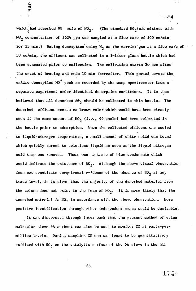
which had adsorbed 99 mole of N00. (The standard N0_/air mixture withj i i.
NO- concentration of 1624 ppra was sampled at a flow rate of 100 cc/min
for'15 min.) During dcsorption using N» as the carrier gas at a flow rate of
50 cc/min, the effluent was collected in a 1-liter glass bottle which had
been evacuated prior to collection. The colle.tion starts 30 sec after
the onset of heating and ends 10 min thereafter. This period covers the
entire desorption NO peak as recorded by the mass spectrometer from a
separate experiment under identical desorption conditions. It is thus
believed that all desorbed N0v should be collected in this bottle. The
desorbed effluent exerts no brown color which would have been clearly
seen if the same amount of K0_ (i.e., 99 umole) had been collected in
the bottle prior to adsorption. When the collected effluent was cooled
to liquid-nitrogen temperature, a small amount of white solid was found
which quickly turned to colorless Idquid as soon as the liquid nitrogen
cold trap was removed. There was no trace of blue condensale which
would indicate the existence of NO-- Although the above visual observation
does not constitute unequivocal cadence of the absence of NO, at any
trace level, it is clear that the majority of the dcsorbcd material from
the column does not oxlfst in the form of NOj. It is more likely that the
desorbcd material i.s NO, in accordance with the above observation. More
positive identification through othor independent means would be desirable.
It W.-IB discovered through Inter work that the present method of using
molecular sieve 5A sorbcnt can also he used to monitor NO at parts-pur-
millLon levels. During sampling NO gas was found to bo quantitatively
oxidized with N0_ on the catalytic surface of the 5A sieve in the air
65
1^1 7 „*"t ~

oxyf.cn environment. The oxidized N02 is subsequently adsorbed by the 5Ai
sorbcnt. This technique cnn also be adopted here to verify the Identity
of the NO, sample-column der.orption product to see whether it is indeed
in the form oC NO. A lonp. Glass U-r,haped column is prepared with both
its front and rear legs each filled with - 0.5 p, of molecular sieve 5A.
The bottom U-shaped portion Is filled with glass beads. The preconditioning
of both 5A sections is done in the manner described previously.
During sampling a typical flow of the NO,/air mixture with N00 concentration*• &
of 18 ppm Is introduced through the front leg of the U column at a flow
rate of 1 llter/min for 30 ratn. After sariplc collection the rear 5A
section alone is dcsorbed first in the usual manner with no NO peak
found which indicates that all the NO™ sample has been collected in the
front 5A section. After denorption the rear 5A section is allowed to cool
to room temporaturo. Thereofter, the front 5A section is dosorbed with
pure N,. as the carrier f;as entering through the front inlet at a flow rate
of 100 cc/min. In the meant fine, the j;l ass-bead filled U-shaped portion
is immersed into a dry Iro bath. The. desorptlon of the front 5A section
yields the same NO peak area as the no ITU 1 sinslt—column experiment.
Upon completion of the front 5A section dcsorption the dry ice bath is
removed and the entire column is allowed to return to room temperature.
Now the rear SA section Is dosorbed ar,»in to ensure that nothing dosorbod
from the front' T>A leg has bcon trapped either in the rear 5A section or
the (I trap as a result of the* coolinj1, of the effluent by the dry-ice bath.
No NO peak was found during this tirac, as expected.
(.f.

IThe above procedure is repeated with u newly prepared 5A double column
itt the same manner until the. stage of front 5A section desorption. Instead
of using pure N as the carrier gas, air is chosen ir the desorption of the
front 5A section. Contrary to the result when N? gas was used as the carrier
gas, no NO ion peak resulted from the desorption of the front 5A section
with air flow acting as the carrier gas. Apparently during desorption
it is NO, not -NO-, that actually cones out of the 5A column. As this
desorbed NO is flushed out with air flow and subsequently cooled •>" . passing
through the dry-ice cold trap, it is oxidized back to N0? on the surface
of the rear 5A section arid adsorbed thereon.
On desorption of this rear 5A column, the NO ion peak reappears,
which further confirms the above mechanism. It is interesting to note
that the existence, of the dry-ice cold trap is crucial to this experiment.
In a similar test the U-shaped portion of the column is immersed in a
water bath at room temperature instead of the dry-ice bath chosen in the
previous work. As a result'of the insufficient cooling, the rear 5/\
column failed to hold the NO desorbed from the front 5A section. This
falluro. could either rc-flect the inefficlvnt oxidation condition at
higher temperature or simply the breakthrough of the oxidized product—N0_—
at such a high temperature. No further investigation was conducted on t'\Ls
interc-'St ing subject.
It sccns clear from both visual observation and the double-column
experiment that the major desorbi'd component under the present experimental
condition Ir, NO, an a result of cert.iin choiim-.il re-art tons. One .likely*J / OF"
mechanism, as discussed in the p rev ious r epor t , ' * ' r i -r converting K0_
to NO is th rough the N0«-water r eac t ion [Ro.n't U'lis (4) am. ( ! "> ) ] . D u r i n g
der iorp t ion l l ic c a r r i e r gas is d r i f d v E l h b o t h » civ.::,u'rr i a l dryer- and .1
1V(>--

P20, prdaycr; Lt Is unlikely that a substantial amount of water moisture
could enter the column and participate in the reaction. If said reaction
docs occur on the molecular sieve'during desorption, then some water
must be retained by the sieve crystal that survives the preconditioning
treatment. It is found that NO- recovery is linear with respect to the
NO- sampling dose up to the breakthrough region. A substantial amount
of water would be required to account for the conversion.
One other possible mechanism to account for the formation of NO is
through thermal decomposition of NOj.
2N02 -> 2NO + (X, (6)
In the gas phase this reaction boa Ins at 150°C, and the extent of
conversion is 5X at 184°C, US at 279*C, 17% at WC, and 10Q£ at G20*C. 29
Under the present desorption conditions, the temperature of the sorbent
generally only reaches 24r>°C at the e:ul of desorption. This corresponds
to only ~ 10% decomposition according to Lite above decomposition scheme.
Tin* nvjch higher NO»-rec«)Vt<ry-rato data of the. present experiment, which
is to be discussed in a Intor section, either indicates that the
decomposition of N0» on thv molocular sU-vo follows a much higher rate
than that suggestt-d by tho p,as phase decowposit ion or that tl-^ thermal
decomposition constitutes at most a minor contribution to the formation
of NO.
2. IVrcent Recovery of NOj, from tho Molecular Sieve 5A Column
It is notoJ in this report that all recoveries for N0» experiments
are expressed in terms of the NO ion integrated peak area nr. recorded
by l ho nass sjnvt romet or. Tho calcul .;t ton of absolsstn percent recovery
177"

©f N02 from the molecular sieve requires the. detail knowledge of the
adsorption and desorption mechanism of N0? under pre-sent experimental
conditions. Since it has been established—based on the tests described
in the previous section—that the major component de.sorbed from the
molecular sieve 5A is in the form of NO, it Is logical to express the
percent recovery (1'R) in the form of
/Mmole of N02 adsorbed\ [\\malo of NO desorbedAimole
The first term of the product is comraonly referred to as ".-ulsorptioa
efficiency," wliiie the second is referred to as the "stroJchiometric
factor." In the present case the value of 1'K is equivalent to the
s-Coichiometric factor since the adsorption efficiency of 100% it; readily
achievable unJor the present experimenlaL conditions. The amount of MO
sampled Is known for a given j'.amplinj; condlt ion. The uinolu amount of NO
dcsorbed is obtained by measuring the clesorption NO ion-peak area r<corded
by the mass .spectrometer. The calibration of the NO peak area, which is
described in detail in a later section, reveals a peak area of 48,905 iuV-sec
for each iimole of KO detected during dosorpt ion ustnj; air as the carrier
gas with a preset ion source pressure which corresponds to c !-„ ion
intensity of 6.8 x 2'J6 unit.
PR j i i iRole _of NO desorbod\ . in t )r/\ umolo of NO sampled ) ' "
J _________ _ ___________of N09 sampled) \ 48,903 mV-sec/imiole NO delected J 'elected J
69 1.78*-

•f
Theaabove equation can also be written in a more common form, i.e.,
/ 1 \ /NO* re.kare-, 68x 256PR " \ £TolE N n7lod) ~ "487905* I j / * 100%
/ X / + \K- I J-M.-IJ.H- ---r ».t-. ir - .iLj -a ••j.-^anm -TUT, n I I AV—.. J Jl5 J i V-l* . •. V A ' f\ 1 Q H I V 1 fi O*/ fQ^
1 i ' r **r\ i i I I T ** U»vUJD / ** J.UWA V 7 /\ mole of M> sampled/ \ 1-- /
where !„_ is the ion intensity of m/e * 29 whose value can be set higher
than 6.8 x 256 unit in the event a larger ion-sonrce pressure is desired
for a more accurate measurement.
Table VII shows an average desorbcd NO ion peak area of 11,619 mV-sec/
Vimole of N02 sampled. The average percent recovery of NO is readily
obtained from Kq (9 )
11,6.19 raV-sec/umoltt of N0? aampled
P R = ~ < ~ ~ ~ - ' ' X
= 23.8%
The above- result indicator that for each imolo of NO., sampled, only
0.23 pmolo of NO is doaorbi'd under the present dt-sjorpt ion condition,
assuming that all drsorbt-d i-onipononts exint in the form of NO which is
subsequently measured by ihe mass {-.poctroraet er. Apparently dnrinj;
de.sorption a substantial portion of the adsorbed NO nas is either not
do.sorbed under the present dosorpl ion condition:; or dosorbod in a form
other than NO [such as HNOj from Reaction (4 )J and fails to reach the
ion source for detection. One obvious approach to iwprovinj; the percent
70

recovery of NO- is to further increase the- temperature of the sarapl injl
column during dosorption. However, the recovery was found to be- '
Insensitive to desorption temperature up to 300°C. No experiment was
done for desorption with temperatures higher than 300°C since a portion
of the column materials (Teflon valve) cannot withstand much higher
temperature.
It is interesting to point out that the current result is also in
accordance with the previous observation which shows the adsorption
capacity of the molecular sieve to decrease with repetitive use of the
same sieve material. This could indicate either that part of the sites with
adsorbed K0? are not reversible upon desorption and thus decrease the NO-
adsorption during a subsequent adsorption or simply the collapse of some
sieve site after such a desorption heating.
The measurement of N0? recovery was also carried out by Mic titration
method, the details of which are described in the previous? section.
During desorption the effluent is collected in the 1-litor f.lass bottle
and subsequently added with 6 cc of 3% 11?0~ solution. The dosorbed NO
gas is allowed to react witli 'U0_ according to the following equation
2ND + 3H 0 -> 2HN03 + 2H 0 (10)
Any trace amount of KO^ existinp in the effluent is also converted to
nitric acid by Kq (1 ). The formed UNO,., as well as any possible nitric
acid directly douorbod from the sieve, is then titrated with the NaOH
solution. The results of N0« recovery expressed an the- ratio of ymolc
of UNO- detected to |:im..lo of NO sampli-d aro 0.29 and 0.31 from two
experiments with an avera},^ of 0.30. This valur is slightly higher than
Ibu-

the percent recovery obtained from the mass-spcctronustric method. This
Is probably an indication of some .-.hcmlcals other than NO that arc also
desorbcd but are not detected by .e mr • spectrometer or yield a
relatively lower NO Ion signal than jf NO gas.
NITRIC OXIDE (NO)
A. State-of-Art Review
Nitric oxide (NO) has long been recognized as a significant air
pollutant. Although it is toxic in hijjh concentration, the major concern
is due to its quick conversion into the more dangerous nitrogen dioxide
( 2) in atmosphere. Many techniques now are available commercially for
monitoring nitric oxide in ambient air. However, most of them such as
chemilumincscent, photometric, coulometric, and electrochemical-cell
techniques require some rather elaborate instrumentation and are not
suitable for personal - u..-1 ing as dictated by NIOSil specifications.
Perhaps the method of largest interest is to oxidize NO into KO,,
and determine the latter by the colorimotric analysis either in the
continuous mode" or by integrated processes. Many extensive studies-'*-
have; been devoted to the oxidation of NO. These studies propose the
systems using such compounds as a mixture of KMnO. and IUSO, , oy.onc,
heated IjO,., acidified MnO,, periodate, persulfaU', •$..()-, CIO™, oxygen,
and CrO- as oxidizing agents. Each method, however, either suffers the
problem of quantitative conversion of NO into K0_ or requires the strictly
controlled conditions that leave something to be desired for the personal
sampling of present purposes.

Most commonly used solid adsorbers such as molecular sieve, alumina,nd gel, and active carbon arc not capable of absorbing NO physically
under the ambient condition. However, one acid-resistant moloular sieve,O/»
namely AW-500, manufactured by Union Carbide has been reported
successful in converting high concentrations of NO from waste gas streams
in a ntrric acid plant into NO* which is subsequently adsorbed on the
surface of the molecular sieve surface. No work has been reported using
the technique in monitoring NO in the lower concentration commonly existing
in the anhient air. Since it is closely associated with the type of work
currently underway in this laboratory, tills technique will be further
explored here in our first-stage effort.
One other technique which is also of high interest to this study is
32a method recently developed by D. A. Lcvngii and coworkers using
a triethano.laaine (TEA) solut ion or a TEA-impregnated molecular sieve
to differentiate NO,, and NO existing in ambient air at sub parts-per-
million levels. With a flow of air stream containing N0/N0» passing
through the reagents, it can quantitatively retain K0? while letting N'O
escape unaffected or with negligible loss.
One ideal solution which would cteot the goal of the present work of
monitoring K0/N0» at concentrations of NJOSH concern involves the
successful adoption of the two above-nu-nlioned techniques. First, a solid
sorbcnt will be chosen that not. only can adsorb and de-sorb NO, quantitatively
but also is capable of convering NO completely into N0» within the sorbt-nt
and adsorbing it subsequently. The recovered K0« from the {sorbent should
yield the total ai.Kuint of NO and N0.; i n i t i a l J y colU-cti'd from the air
stream. Second, a parallel adsorption procvss will be conducted uwing the
7.'!is:

chosen sorbent column attached with a TEA-itnprugnatcd molecular-sieve
pfecoiunm that allows the measurement of NO alone. The difference
between the two measurements will represent the Initial NO, concentration.
As shown by the preliminary test results presented in a later section,
the originally chosen molecular sieve 5A has largely fulfilled the
requirements of the present tasks.
B. Experimental
1. Experimental Procedure
The molecular sieve 5A is first chosen for evaluation In view of
its success in the work of N0? adsorption. The detailed experimentalt
procedures largely follow the previous work on NOj unless otherwise stated.
The amount of molecular sieve 5A used in each sampling column was
originally set at 0.5 g which is the same as in the work on NQj- However,
it was found that this amount of 5A sieve is not adequate for the
quantitative oxidation and adsorption of NO samples under typical
sampling conditions. A greater amount of 5A sieve ranging from 1 to -'* g was
used in later work. The longer preconditioning time was required for
each colunn for tho greater amount of sorbc-nt sieve used.
2. Calibration of the Standard KO/N, Mixture
A'2000-ppm NO/N standard mixture wit ha reported accuracy of + -20 ppm
was procured from Union ():irbidc>. Tin NO concentration of this standard
mixture1 war, calibrated with tin.1 tilrat ion mot hod in a mantu - similar to
that described in the work on NO^/alr mixture calibration. riefly,
the; gas mixture war; Introduced into a glass bottle of .1093 c with
known t o t a l pri-ssutv. To this mixture 6 cc of 37, ^2^2 K0^ ml WJS

added. The bottle wan then allowed to be settled for 2 hr with
occasional shaking. The NO gas was expected to be oxidised by ll_02
into nitric acid according to Reaction (10). At the end of this period
the solution was withdrawn into a beaker and titrated with 0.009 N
NaOH solution. The NO concentration of the standard mixture in ppm can
be. calculated by. an equation similar to Eq (2 ). Two .experiments yield
results of 1840 and 1908 ppm with nn average of 1874 ppm,
The above calibration technique was also standardized by calibrating
a pure NO gas through an identical experimental procedure. It was found
that the above calibration method generally yielded a result ~ 5% lower
than the actual value. This loss of 5% is probably duo to the incomplete
conversion and sample treatment of t.he present experiment. By taking
into account this 5% loss, the acceptable value of the NO concentration
should be 1973 ppm, with acciuaey of + T>Z.
3. Calibration of Inlc'j'.ratod Peak Area
Tho correlation between t.lu1 actual amount of NO introduced under a
given flow condition and the mnss-Hpcctromotrically recorded peak area in
nV-scc is obtained in a manner similar to that in the NO, work. The
standard NO/N' mixture with NO concentration of 1973 ppm Is used as the
calibration gas. During calibration thin mixture is introduced at a flow
rate of 100 cc/min for a period of 10 min. The amount of NO- introduced
is found to be
1S4--

During the same period a fraction of this flow is also introduced into
the ion source of the mass spectrometer. The ratio of.I_._ ion (NO ) to
I-- ion ( N N4) was found to bo 0.3025. -An integration of the I,- ion
signal for a period of 10 min with the I_Q ion set at 6.8x256 yield
a total value of 3,059,320 mV-sec-. Thus, the integrated peak area per
praole of NO detected is
3,059,320/80.2 = 38,146 mV-sec/praolc- NO detected
Note that the above calibration van obtained using pure N, as the mixing
gas. In the case of desorption where air is used as the carrier gas, a
correction factor of (1/0.78) should be applied to obtain the actual
amount of NO detected by the mass spectrometer.
4. Preparation of Tritithanoaminc 1'recolunm
A trtcthanoamine (TEA) impregnated molecuLir sieve procolunm was
used in the present work for the- differentiation of NO and N0? Rases.
The preparation of this agent follows the same procedure as that described32
by Levaggi. In brief, add 25 B of triethoalamine to a 230-mo beaker;
add 4.0 f, of j-.lycerol, 50 cc: of acetone,- and suffie[ent. distilled water
to dissolve. To the mixture add about 50 cc of 45/60 mt'.<;h molecular
sieve 13X. Stir and let stand in the covered boakor for about. 30 min.
Decant the excess liquid and transfer the molecular sieve to a flat
glass pan. Place under a heating lamp until the bulk of moisture has
evaporated and then in an even at 1IO"C for 1 hr until dry. Store in
a closed ^lass container.
76

C. ResultsI
2. Oxidation Capacity Test
The first logical investigation on molecular sieve 5A is to test
whether it is capable of catalytically converting incoming NO into NQ_
in the environment of air oxygen, and what is the minimum quantity of sieve
material required for a complete conversion. After the oxidation stage, the
adsorption and desorption processes are expected to follow the came
pattern as in the case of WO^ experiments since exactly the same chemical
identity—N0~—is under consideration as soon as it is formed, • However,
it is clear from later discussions that the adsorption of the oxidized
NO- appears to follow a somewhat different mechanism.
In the first test, an arbitrary amount of 0.43 g of molecular
sieve 3A with a thin layer of l'0r was packed into a 1/A-in. O.I). U-tube
column. After preconditioning in the usual manner, a 40-ppm NO/air
mixture was allowed to flow through the- column at a rate of 500 cc/min
for 15 mln. During the same period a portion of the after-column effluent
was introduced into the ion source of the mass spectrometer for monitoring
NO gas escaping from the I' Or-5A cojurcn. A clear sharp increase of the NO
ion level was observed at the beginning of NO/air flow. This ion signal
rer.'.nint'd at an elevated level over the entire sp.-in of lr> nin and gradually
came back to basic: lino after said period when the NO flow was closed,
Th.is certainly indicates thai some portion of the- NO initially introduced
had fscapc-d from the sorbont column, although the quantitative amount was
not established in this t'xpor iir.t-nt.
77
In the second test, two columns eadli with 0.5 }; 5A were attached In
tandem. When the same NO/air mixture as in the first tent was allowed to• . . ' , ' . . '•***' ' ' '
flow through the columns, the escape of NO was no longer observable in the
mass spectrometer* The dcuorption as done in the usual manner shows the ratio
of the integrated NO ion Intensity of the front column to that o£ thu rear-
one to be greater than 1000:1. It is concluded that the molecular sieve
5A is indeed effective in catalyzing the NO oxidation reaction under
typical sampling condition-!.
2. Recovery as a Function of NO Concentration Leveland the Amount of Molecular Sieve 5A
One other crucial test in the present evaluation was to check the
completion of oxidation over the whole range of NO concentration of
N10SH interest, namely from 2 ppra to 40 ppm. At low concentration the
oxidation rate is expected to be slower if the.1 rate is proportional
to the NO concentration to the second order as shown In gas-phase kinetic;!.
This will be reflected in the abnormally lower unit recovery for the low
NO concentration adsorption. On the other hand, the- oxidation will not
be completed at the high NO conct-ntralion end if tV ' amount of sorbent
employed is lower than thai required for ;i complete conversion.
In the test the recovery'of 110 is measured as a function of NO
concentration using columns that contain O.T> j;, 1.0 g» or 2.0 g of
molecular sieve ">A. Tor a constant adsorption linv of 15 win and
dry-air flow rare of T)00 cr/min, each type column was adsorbed with fivi-
different NO/air mixtures, wit l i concentration ranging from 2 to 40 ppm.
Those coluwns were procond i t loned and dvsurlu'd in I ho :;ami- maniK1)' as
that dfscribi-d in tlu- NO work;
78

The results of the above experiment are shown in Fig. 11 . It is
st&en from this figure that, except for NO concentrations higher than
40 ppra, all recoveries arc linear with respect to NO concentration for
all cases where three different amounts of 5A sieve were used. However,
the recoveries increase progressively as the amount of 5A sieve is
increased. This is expected If a lower amount of 5A sieve is inadequate
for the quantitative oxidation of the sampled NO gas.
The effect of the amount of 5A sieve was further investigated .by
varying the amount of molecular sieve 5A in each column ranging from
0.5 g to 4.0 g. Each column was adsorbed by a NO/dry air mixture
(NO 22.1 ppm) with total sampling rate of 540 cc/niin and a times period
of 15 min. The desorption results are shown in Table X . Within
experimental error, the recovery increases with incroa.se in tho amount of
molecular sieve but levels off as more than 2.0 g of 5A sieve Is u^cd.
This clearly indicates that tin: quantitative oxidation find adsorpi ion
of NO has been achieved with 2.0 p. of 5A col 11:1111 tinder the- present s/inpling
conditions. It is anticipated I hat rtore tJun 2»0 5; ol molecular sieve
5A should be used for sanpli'ng the KO/air r.i»turc at higher concentrations
or longer periods if a quantitative oxidation and adsorption of NO is
des-irt-d. It is suggested that a lesser' .ir.vn-.mf of .'>A column is s t i l l
acceptable for monitoring !•'') since the recovery of No during dosorpt Ion
is linear wirh the actua] ICO cuiu'ent rat ion l.-vel a:; demonstrated in
Kig. 'I . This is especially I ruo where a lesser .'iniintut of IA si<-ve is
dc'Siraiile in orJer tci reduce the flow res ist.utce durin;-, air s.-tnpl in:-..
iss-

oo>w;»E
ID'O
til<r
uQ.
HQ.o:oO)LJQ
ccou.
6r 3
0
- 2 -
AMOUNT OF M.S. BA
0 10 20 30 40
NO CONCENTRATION (ppm)
50
' ( ,1-1, ,"1| • . i t ! , »n ,-Mli!
iss-

.-*•»• •• ',*'" • '
. '•';','
Column
1
2
3
4
5
6
. . . . - . . ,RECOVERY OF NO .AS A M' CTION ,0? ,THE
AMOUNT OF MOLECULAR,SIEVE >A.',
Amount of Halcciilar5A
0.5
1.0
1.5
2.0
2.5
Disorption Peak, Areaper jiniole of NO S
19,249
21,618
23,923
24,340
23,646
24,458
a,.Column: as dosovlhi'd in '•';«!)I(• V I I .
> i i m p l i m ; Cond i t iun:. St-a»d.in| NO/N, - w i x i u t v -(NO 1973 ppm) IKwixt 'c i w i t h ili'y air l<i y i o l c l n ' f t n . i l nux iure luivjo;- a loi.it'f l o w ra te of *>'ifl c f / i n i n .-incl Nil conn-nt r a t i o n 22 .1 |ip;n.S a w p l i i i j ; t {.MI- - \'y runAmount, of N'ii snriplcd -• 7. J-'» t ^ R u l oS a w p l i i i j ; t {.MI- - 1'> n i i nAmount, of N'ii sririplcd -• 7. J-'» t iRu lc

Ta
One other noCcd phenomenon in Fig. 11 is that the recovery of
NO for 44 ppm NO data is consistently lower than the expected value by
- 10%. The possibility of experimental error is reasonably ruled out
since the loss of recovery appears on all three experimental data. The
explanation based on the insufficient oxidation of NO sample on the 5A
sieve is unlikely since one would expect a remarkable improvement of the
NO recovery when the amount of molcculai sieve 5A is increased from 0.5 g
to 2.0g. This improvement is not seen in the 44 ppm NO data.
It is clear from later discussions that the adsorption and dcsorption
of the surface catalytically oxidized NO,, seem to follow a different
mechanism from that which accounts for the adsorption and desorptlon of
natural N02. As a result the desorption NO ion-peak area per urnole of
.(.MO sampled is more than two times greater than the desorption NO ion-peak
area per pmnlc of NO. sampled. One plausible explanation for the
discrepancy of the 44 ppm NO data is the possible premature oxidation of
NO in the: NO/air sampling stream before it enters the 5A sieve r.olumn.
The prematurely oxidized N0?, after being adsorbed on the 5A sieve
sorbent, will yield a much smaller NO peak area upon desorptiou. The
premature oxidation of NO is prominant. only at high NO concentration
since it is known that tho oxidation follows a s.ccond-qrdor mechanism
in tho gas phasic. This appears to be in agreement .with, the observation.
To further test: the. possibility of this theory, two adsorption experiments
were conducted with the 2.0 g 5A sieve columns in sampling a NO/alr
mixture with NO concentration of 110 ppm at a flow rate of 113 cc/min for
a period of 30 min. The dcsorption of these two colum.is yields a recovery
82

of 13,849 and 13.880 mV-sec/ mole NP—more than 40% lower than the*
established value. This clearly demonstrates that the premature oxidation
of NO is the real cause of the apparent decrease of the NO recovery in
sampling NO/alr sample with higher NO concentration. It also reflects
the fact that there is no need to monitor NO iit ambient air with concentration
much higher than 40 ppm sLr.cc the NO will convert i.nto NO- In a matter
of seconds.
3. Reproclucibllity of FO Sorption with MolecularSieve 5A Column
The rcproduclbility test of NO recovery was dona with n modified
column containing 2.0 g molecular sieve 5A, Each column vas preconditioned
hy heating to 300°C while purging with dry air at a flow rate of 100 cc/mln
for 2 hr. During sai,.;iling a NO/alr mixture with an NO concentration of
111 ppm was Introduced into the sampling column at a total flow rate of
540 cc/mlu for a period of 30 mi.n. Table XI shows tiie results of four
identical experiments with an average recovery or 24,240 mV-scc/umole NO
and standard deviation of +1.1%. Reproducibil i.ty is, therefore, seen
to be very .satisfactory.
4. Adsorption of NO with Ambient Air as the Carrier Gas
To test the effect of moisture on the NO oxidation and adsorption,
a:nbient air with temperature oi 80°F and relative, humidity of 40% was
used as a carrier gas in the NO adsorption. Adequate amount;: of ?nQrt
were placed J.n front of each J-g 5A sieve column. The. cxpei imental
procedures are identical to the description given in the previous section.
83

TA15LE XI
REFRODUCinUITY OF NO oORPTlON WITH KOLECULAU SIKVE 5A COLUMN0
Column*Li_.
I
2
3
4
Uesorptlon l.Q PeArea (mV-sccj
akc.d Desorptiou Peak Area pervsroole of NO Sampled
182,226
178, ::i
177,238
176,724
Average
Standard Deviation
24,826
24,289
24,169
24,340
277
'Column: 2.0 g of molecular sieve 5A with P?(V prcsection in a 8 tmn00 j;l;iss tube with its rear end attached to a Teflon valve.Each column is preconditioned by heat ing to JOO*C whilepurging with dry air at a flow rnte of 100 cc/min for 2 hr.
Sampling Condition: Standard NO/tL r. ixture (NO 1973 ppm) is mixedwith dry air to yield a I'mul mixture with NO at 11.1 pj>inand a total flow rate of 541 cc/min. Sampling time = 30 min;Amount of NO sampled = 7.34 pinole.
CI)csorption Condition: The column is heated to 240°C with pure Ncarrier gas at a flow rate of 100 cc/min.
-All masi-spc-ctrometrically recorded peak areas "Jn this Work were
obtained in reference to a constant !„„height at 6.8 x 256.
peak
84
15.U-

It is neon from the rctiult.it presented Jn Kip,. 17 that the agreement
with the dry-air expx r li-u»nt Is good within experimental crr*>r. Tt should
be noted that a l*2 s Proc°lunm I'lyer is nlwa.y*t provided -even for the dry-
ai.r cxp'crintents to avoid aoy accidental contact" of the sieve material
with moisture.
5. No Storage Experiment
In order to assess the capability of the molecular sieve 5A column
in retaining the collected sample for extended periods, a scries of NO
storage experiments was conducted w'lh the sample column stored for a period
ranging from 1 day ro more than one month after sample collection. The
column and sampling condition*- adopted in this experiment are essentially
identical to those described in Table XI for the reproduc.ihil.ity test.
During storage the Teflon valve of the column Irs closed and the front
end of the column js .scaled with (in o-rlng joint cap.
The results arc shown in Table- X1T. The IOSK of NO'recovery is
seen to bo much Jargcv than tliat: in the case of N0«. There ifi - 8% lows
of NO recovery after the first week of storage, and this Joss Jumps to
- 15% a*, the end of the Jsocond week. The enormous fluctuation seen
in the recovery data suggests that—in,.,,add i t ton to the storage time
effect—the- Ions of NO recovery in also somehow influenced by the condition
of each individual sampling column. The. cause for this deterioration iy
not clnnr, although the po:;;;ib1c contamination of water moJ.Uurc is again
considered as the prime reason for the loss of i!0 recovery. The
inclurion of correction factors 10 account for the loss of NO after
s.orago should a.lr.o be feasible, •* I though the detailed correction procedure
may require some furtlicr experimontal work.
B3 l.S-i

o0>(A
in'OX 2
tuo:
uQ.
O
G:oCO
°0 10 20 30 40 50
NO CONCENTRATION (ppm)
iv !!'. i!1^ lleroviM'V as a I ' l in i ' l imi of NO Concrnt rat ion I'siii!1,Ai ' i ' . ' i i -nl Air a.1. S.-impl i u('. M i x i u r o ';.•!•;
A n ! i ' - M i l a i r U'i ; i |H irat t i r i - o f WlT; r t ' t a l i v i - l i u i v i d i t y oColni::n: 1.0 }•, < > f no U'I:H I ;ir s i i - v i 1 'i.\ in I In1 n o i H l i i ' d s.'inip'i in j*rol.r.n (si-i- T a l ) I i - VI I )A d : > o r ; > t i n n : N f V a j - . U i f i U :i 11' ,".>s r i i x t i i n 1 v . ' i l h i 'Jnv.' r a t f of">')') c r / i ' : i n ,1111" ; idsoi p t i i M i l u - r i o d o f I ' i n i n .D . i s ' i i - d I i in- j r , r r |> rod iuvd I row ih.1 l . ' l - j - r>A s i i - v r r u l u r u I i noo! i ' i j - . II.
1:35--

TABLE XII
HO STORAGK EXPERIMENT DATA
ColumnNo.q
1
2
3
4
5
6
7
8
9
Storage Tiruc.(day)
1
2
3
7
7.
14
14
21
34
Desorptlon I_nPcakc Area
(mV-scc) ^
168, 08'
17-!,055
160,866
163,565
166,513
150,793
155,649
146,891
142,572
Peak Area perpinole of N02SampledB(my~sec/mnplc)
22,900
23,.>22
21,916
22,284
22,686
20,544
21,206
20,012
19,424
Rattod
94.1
96.6
90.0
91.6
93.2
84.4
87.1
82.2
79.8
Column and Sampling Condition: An described in Table XT.
During storage the Teflon valve of the column is closed and the frontend of the column is sealed with an o-ring cnp.
cDesorption Condition: As describe! In Table XI.
Ratio is expressed as the rjitio of the value in Col. 4 and theaverage value (24,340 mV-soc/v:molo NO) obtained from Table XI.
87

Experiment?: wore also conducted to examine the NO recovery for
samples that have been stored under abnormal conditions such ass
•extremely high ambient temperature or low pressure. Columns 1 and 2
of Table XUX reveal the recovery of NO for sample columns that had been
stored at a temperature of 130°F for a period of 21 hr. Unfortunately,
the loss of NO Is too large to bo acceptable. As shown In Cols. 3 and 4
• o£ the s;ame table, the experiments were repeated In n similar manner
except that the column was stored at a lower temperature (120°F) and for
a shorter period of time (6 hr) . The results were found to be very
satisfactory. Apparently there is no complication caused by the lower
ambient pressure. As shown by Cols. 5 and 6, the recovery of NO is
practically unchanged after the sample column has been stored at 500 torr
for a period of 22 hr.
6. Passage of NO Through TEA-ImpregnatcdMolecular Sieve Pr ('column
The test of passage of NO through a TEA- impregnated molecular sieve
32precoltimn has; been conducted extensively by the group of I). A. Levaggi
at the. sub parts-per-million NO concentration level. The purpose of the
present work was to examine the same passage over a range of NO
concentration of NIOSH interest; namely, 2 ppm to 40 ppm of NO. A glass
tube of ]/. mm CXI), containing 1.37 g of the TEA- impregnated molecular sieve
was placed in series with each I'2°5~5A (1-0 g) U-tube column tested. The
experimental conditions arc the same as those described in section 2 above.
The results are given in Fig. 13. It Is seen from these data that the
unit recoveries of the present data are essentially the same as those of
Fig. 11 within experimental error. It is, therefore, established that
88

Column
TABLE XIII
STORAGE OF NO SAMPLE UM)ER ABNORMAL CONDITION
Storaj
Pressure Temperature Time
Desorption PeakAreac nor moleNO Sampled(mV-sec/ mote)
Ratio
12
3
4
5
6
760
760
760
760
500
500
130
130
120
120
80
80
21
21
6
6
22
27
18,986
19,819
24,182
24,258
25,099
24,800
78.0
81.4
99.4
99.7
103.1
101.9
Column: I' Oc " 5A sieve (2.0 g) column; column preconditioned in
the same mnnncr as in TnbJe XII.
Sampling CondirJon: NO/dry nir nixture (NO 11.1 ppm)sampled at a flow rate of 540 cc/min fdr 30 mi.n.
During storage tlie Teflon valvo of the. colunn is clodcd and the frontend of the column is Kcnled witli an o-ring joint cap.
''Dosorptioa Condition: Same as described in Table XI.
Ratio is expressed as the ratio of the value in Col. 5 and the averagevalue (24,340 mV-sec/iimolc NO) obtained from Table XI.
891*38--

ooV)
in'O
UJo:
UJCL
7. 'ga.a:ocoUJo
/y
0 10 20 30 40
NO CONCENTRATION ( p p m )
50
Fi j'.iirc 1'i. ''i.'CiK.'L'1'y o ( ^'0 ;»; ;i l - 'unct i i ' n ft' X'1 ( 'onconl r;it ion Ust i l ; ! ! - S l i - V i - r)A Co lu , - ; i
S.'iuipl inf , Com! i t ion: N O / d r y a i r r i x t n r c is s.'ir-plod ,\\. ;\t u l . i l I I m: r;iti ' of Vl ' t ri: /r . .(n :'.'. ] r> l a i n .Pns'u ' t l 1 i in' is ropi 'odncoil f n > r , l in - I .0- p r>A siovi- c o l u m n1 inc of l ' i > ' . I I .

SO at concentration*! below 40 ppm in air can pans the TEA agent completely
unaffected or with only negligible loss.
I). Discxission
1. DesorptIon-Peak /Nnalysiii
As discussed in the previous report on t."0_ work, t1u> molecular sieve
5A Jesorption-peak shape was found to be highly dependent on sieve
preconditioning, although the total peak area remains unchanged. With
higher preconditioning temperature (> 250°C), it is clearly seen during
desorption that there is actually a second, f;mnll broad peak riding on
the tail of the first larj,<_-. sharp peak. Further resolution of these
two peaks was recently attempted in a column containing as much as 13 g
of molecular sieve 5A which was preconditioned by heating to 300*C for
a period of 5 hr. Two desorption pciks wore largely resolved under
nornal desorption conditions.. There wore reasons to believe that this
second peak nii;ht be caused by a partial breakthrough of the; nitric acid
forncd during column desorption. However, from the mass spectra recorded
at various positions of tluine two desorption peaks, it was discovered
that the N0_ (m/o»46) ion—which is an intense ncak ion in the UNO-
spectrum—was not observed aloni; with the NO Jon corresponding to» • i .
the second broad peak. It thus appears thai this second peak is also
an ion formed from NO, although its origin i;; still not clearly
understood.
The double-peak phenomenon wan also observed in the desotpLtcr. of
columns adsorbed with NO. The ratio of tlio first-peak area to that of the.
second peak is larger than 'i:l for the adsorption of high NO concentration
91.
SiCO-

*
(40 pjira) but gradually d'"*ruas«H tu - 1:1 for u:c KO concentration of
2 pp:n. Therefore, it 1» the total dcsorption peak arc'i rather than the
area of any individual peak tli.it 'ahould bo counted In order to ensure a
uniform unit recovery over the entire range of NO concentration.
2. NO Adr.orpt lon-De.sorpt Ion Mecltanir.m
It Is reasonably well established that during the u.inplinp. of NO gas
in the al_r utrc.tm with the r.oleculai sieve 5A column, NO can bc« oxidised
on the catalytic surfnc<! of the 5A sieve into NO according 10 the
reaction
2NO -h 02 -» 2N02 (12)
The oxidized K0« is then adsorbed !;y the molecular sieve 5A sorbent.
Quantitative oxidat lon-adsorption can be achieved provided t:,: amount of
5A sieve is adequate—the value belti£', dict.ited by the actual s.-ur.pl in;;
condition such us NO concentration, total re.nct.ion time, etc.
In the previous •••ection dealing with NO work a double b.\ siieve
tantl:."t column was? used to examine the deaorplion meclKinism of the N0«-
adsorbed column, tt wa« concluded tl).it the major identity of tne
desorption prsulucf exLsttj in tb-j form of NO. It is of e<|ual inlerest in
the present work to determine whether I be name niech.'in ism is followed
durin;; d'.-sorptioti of the r)A sieve column that has sampled the t.'0/alr
mixture. The same long gla.ss U-shapt-d column with each leg being filled
with 0.5 g molecular sieve 5A was used in tlu- present test. After
sampling the KO/air mixture (NO 22.1 ppn) at a flow rate of S'.O cc/mln
92

tor a period of 15 min, the front 5A sieve- section was duaorbed using ML
.is the carrier gas while the rear section as well as the U-trap section
+was iinmersc'l in a dry-ice bath. To our surprise only a small NO peak
VMS recovered having an area of «i29 mV-scc. The rear 5A sjevo section
was subsequently desorbcd with an NO poak area of 76,064 raV-aec recorded
by the mass spectrometer. The only plausible explanation for this finding'
is that the major component desorbcd from the front 5A sieve column is not
in the form of NO. The most likely candidate which fits the observation
is NO^ although positive identification cannot be made from this test.
3. 1't-rconi. Recovery of NO from theMolecular Si^vc 5A Column
Some difficulty arises In arriving at a meaningful derivation of the
percent recovery of NO from the; molecular sieve 5A column sliice the true
dtrsorption mcclianisn has not been unequivocally established based on the
experimental f ladings.,., Assuminf; a dor.orpt ion product of NO, the percent
recovery c;m be expressed in a manner similar to Kq (6), i.e.,.
iirnolc1 of NO desorbod. ....... xof NO sampled
24,3'tO mV-sec,48,90~r> mV-sec/)ini"le NO delected
« 48.82 (13)
However, as di.icusued previously, the dcv.orpt ion product is more
•likely to be in the form of NO, rather than NO under present oxpi-rinental
conditions. Accordingly, the correct form of percent recovery should be
93

of N0_ desorbedPR « - : -- r-r~r= -- :— : -- X 100%Vimolo of NO sampled
mV-scc /tmolc NO^31,540 mV-sec/umoLe NO- detected
- 77. OX (14)
where 31,540 mV-sec/Mmole NO. detected is the calibrated value for K00
response previously described. Regardless of the actual desorption
mechanism, the obtained percent recovery for either case is substantially
higher than that of N0? adsorption. It is conceivable that the adsorption
of NO. and KO-turned-NO? may follow different mechanisms. In the case
of NO, the adsorption may be dictated by a process closely related to the
catdytical effect of the sieve surface and more readily desorbcd upon
heating. The unexpected high PR value of NO also violates the stoichiomctric
relationship of the desorption mechansitn of 3NO. + ILO -> NO + 2HNO-
prcviously assumed, unless the forned 1KO, can partially break through
or further decompose under the present desorption conditions.
4. Effect of Interfering Cases
In principle any gases existing in ambient air that can be absorbed
by the adsorption tube under the present sampling conditions and desorbed
upon heating-— with the desorption product accidentally also yielding
a p/e = 30 in signal in the innss spectrometer — will interfere with the
present method of analysis of NO and N0_. However, to the author's knowledge,
there is no commonly existing air pollutants that fit the above description
and cause interference to any significant degree.

Among various nitrogen oxide compounds, nitrous oxide (N_0) is<£»
known to exist in ambient atr at considerably high concentrations (several
hundred part? per million) and forms a significant amount of the NO
ion (m/e « 30) under electron impact. Fortunately, it was found in this
laboratory that it cannot be adsorbed and subsequently desorbed with the
molecular sieve 5A column used under the present experimental conditions.
The Interference is practically negligible for an N_0/air mixture with
N^O concentration as high as 2000 ppm.oo
It has been reported that nitrous acid anhydride, N-0~, and
nitrogen tetroxice, N-O,, do not exist at concentrations of 100 ppm and
below. Kinetic data show that their dissociation is practically
instantaneous. Hence, these nitrogen oxides nay be disregarded.
Nitrogen pcntoxidc is rarely found in ambient air because it is readily
hydrated to nitric acid vapor and is also an unstable compound which is
28very sensitive to heat. The reported half-life is 6 hr at 25°C, 86 mln
at 35°G, and only 5 sec at 100°C. The decomposition products are nitrogen
dioxide and oxygen. In is also doubtful whether N O,. can be physically
retained by the 5A .sorbent due to its relative larger molecular diameter.
Probably the most likely gas to interfere with the. present method is
nitric-acid vapor. It is known to be stable, to exist in the atmosphere
at trace levels and to readily yjeld an NO ion in the mass-spectrometric
ion source. However, its adsorption and desorption characteristics on the
5A sieve are unclear at this time. Since it can also be absorbed in many
metal and glass surfaces, it is doubtful whether it can be successfully
introduced into the ion source and detected during desorption. Experimental
testing is required for a better understanding of this potentially
interfering gas.
204-

•f + +In addition to the XO ion, several otlier Ions such as C_H, , C1LO ,£ a I
4*and CH,N also show the same nominrtl mass (i.e., m/e = 30). If the
precursors of these long come as the resulting products of the above
adsorption'-desorption procedure, they should also be considered as
interfering compounds. Although there seems to be an endless list of
compounds that are able to form one of these Ions, probably, very few—if
any—can cause severe interference which will affect the actual measurement.
First of all, the majority of these compounds yield only the iii/e • 30 ions
with intensities much less than 5% of the most intense peak in each
spectrum. Thus, the interfering effect is negligible unless their
concentrations are very hipli in the ambient-nir environment. On the
other hand, most of these compounds that are capable of producing
m/e - 30 ions are generally of a size which is too large to be adsorbed
effectively by the sorbent currently employed which has an aperature ofo
only 5 A.. Furthermore, even after adsorption these compounds may not be
' desorbcd under the present desorption conditions.
In the actual case of interference, there are still ways of eliminating
or minimizing this effect. The difference in mass between the KO ion
(m/e = 30.0061) and the above-mentioned ions (C-H, ion with m/e = 30.070?,
H20+ ion with n/e = 30.0265, and Cil^N* ion with m/e = 30.0498) is large
enough to be resiIved by most mass spectrometer having moderate resolution.
A proper choice of a GC column is sometimes very helpful in separating
the Interfering source and the true ion signal. Other methods such as
trapping and absorption elimination may also prove to be effective for
resolving the interference problem.
96

w. In conclusion, it appears that the present method of monitoring NO-I
and NC>2 is free from the interference of other gases commonly existing in
ambient air. However, more definite conclusions await further systematic
laboratory experimentation.
E. Conclusion ' . •
The currently developed solid-sorhent mass-spcctrometric method has
been shown to be effective in monitoring both nitric oxide and nitrogen
dioxide in ambient air at parts per-million levels. The, sampling tube is
compatible with the personnel~carryable . sampling pump in every respect.
Adsorption efficiency is quantitative for both NO and NO- over the entire
experimental range. The desorption result is . reproducible with accuracy
better than Hh T',* However, the percent recovery for these two gases was
found to be different, probably due to the different adsorption-desorption
mechanisms involved, the details of which are only partially resolved
in the present work.
It should bo noted that although the present method has been tested
only within the concentration range of interest to N10SH, the present
technique can be applied to other ranges provided the sampling conditions and
amounts of solid sorbents arc properly chosen. Thus, a longer sampling
period is desired If the ambient; air with NO or N02 concentration at
sub-parts-pcr-million is to he sampled. On the other hand, in the case of
a stationary source or vehicular-emission monitoring where the pollutants
generally persist in the range of hundred parts-per-mJllion, a greater
a...junt of sieve sorbcnt with a shorter sampling time should suffice.
97

In the present work the mass spectrometer is chosen Cor identification. 1
and quantification of products released from the sorbcnt during desorption.
Analysis using the mass spectrometer is rapid, sensitive, and unambiguous.
However, it may not ba popular due to the relatively high cost of the
instrumentation. In a case where the sensitivity requirement is not
extremely critical, the thermal dcsorption product can be simply collected
and analyzed by the conventional titration method. One possible alternative
to thermal dcsorption is solvent extraction. The central question will then
be the development of a technique for the analysis of the extracted
solution.
98

SECTION VI
INSTRWIENT-COMPUTER INTERFACING AND PROGRAMMING
MS-30
Preliminary work performed on the AEl MS-30/l)S~5n mass spectrometer
33and data system has been described previously. The data system is
now fully operational and several modifications and improvements have
been made. The Data General RDOS operat Ing system has boon modified to
allow the entire system to be run from the CRT terminal rather than the
teletype. The hard-copy photoprinter attachment to the CRT terminal may
also be triggered automatically to provide a permanent record of the
console dialog i£ desired. This increases the ef f iclc-...:y of operation sub-
stantially since the CRT terminal will print approximately 80 times
faster than the Teletype.
34Programs have been written to permit signal averaging of successive scans.
The current version of these programs relies on the rcproducibility of the
magnet scan (magnetic field strength versus tiroe, measured from the
start of the scan) to line up the mass nc<ile for each successive run. The
present operation of the DS-50 data collection is as follows: Each
individual scan is centroidecl on-line us in;; a preset hardware threshold.
The time centroids are also converted to masses on-Line using a pre-
determined time-to-mass scale aa described previously.' The peak
areas and corresponding masses are then stored on the disc. Subsequent
programs perform the desired analyses off-line.
It is not possible to do all of the above processing on-line when sig-
nal averaging since the individual peaks might not be defined im^'l
several scans have been accumulated. It is also necessary to rcmosc the
99

hardware threshold to avoid any loss of data In the individual scans.
Thus,the signal-averaging program makes use of a DS-50 option which
will allow rim "unccntroided" dntn to be collected* The signal-averaging
program then averages the raw data off-line, calculates time centroids and
peak areas using a software threshold, and stores the information on disc.
An off-line time-to-mass conversion progran (supplied with DS-50) is then
used to convert the time centroids to nasses, thus allowing the
remaining DS-50 analysis programs to be run.
These programs have been tested and the rcprjducibility of the.magnet
scans found to be adequate for low-resolution spectra provided the
magnet is allowed to i:ycle at least ten tines before data collection is ini-
tiated. The rcproducibility at high resolution has not been tested.
Ultimately, we would want to consider installing a Hall probe to monitor
the magnetic field strength directly. This would greatly increase the
accuracy in which the mas'! values of successive scans can be lined up before
36the averaging is performed, as described previously. No work has
been done on rewriting the titne-to-mass conversion portions of the ' '
DS-50 data system as yet, as AKI has been reluctant to make these
programs available. It would probably be better (and easier) to write
dedicated timc-to-mar.s algorithms for the particular mass range
desired (320-328) than to try to modify AKl's generalized'routine.
.SPARK-SOURCE MASS SPECTROMETER
No additional work has been done in this area sir-j.c the previous
33report. However, once the above system for the MS-30 is operational, it
should be easy to connect the computer to the MS-7 rsllier th.-\n the MS-30.
100

The only difference would be the possible use of the Hall probe. Hwcvcr,
based on past experience with the reproducibility of the magnet season the
HS-30, an identical solution on the MS-7 would probably be attempted/
Some work would be required to interface the digital linoa from thu
computer to the scan control circuits of the MS-7, Uit this) should
present no problems.
CROSSED BEAM AND CD-/. 91 PROGRAMS
Data acquisition nnd analysis programs have been written for the
crossed-icn molecular-beam apparatus and the DuPont CD-491 GC-MS system.
These programs are capable of collecting data, controlling instrumental
parameters such as scan speed, and performing subsequent analyses,
all using the Hewlett-Packard 21.16 computer with the manufacturer-supplied
DOS-M system. The details of the operation of these programs have been
37- 40described elsewhere.
OTHER COMPUTER WORK
Some time has been spunt adapting computer programs written and
used by one of the authors (D. T. Terwi.llip r) at Purdue University
for use on the presently available Hewlett-Packard computer systems.
These programs Included an operating system for an ItP-2100 series
computer in a non-disc environment as well as ma<;t; spectrometer data41
collection and analysis programs-. The operating system has been
expanded to include the facilities of the disc and the Vcrsatcc printer/
plotter which were not available previously. The system is now substantially
easier to use and more efficient in its operation than the HcwJett-Packard-
supplied DOS-M system which had been used exclusively in this laboratory
previously. Most of the preliminary portions of the programming for the
101

If
spark-source mass b/ectrometcr wore -one on the Hewlett-Packard
computer iistr);; the above syatom, nml portions of some of the programs
used at Purdue-w«rc directly applicable to the problem.
Analysis of the paper-tape output o£ a quadrupole GC-MS system
used for routine herbicide analyses was performed usinfi programs written
under the above nysitem. This GC-MS system consists of a Varian 2740 gas
chroiiuilGgi-apli equipped with a Model 8000 autosampler coupled to a Kxtra-
42nuclear quadrupole maws spectrometer. Data is acquired by a
Spectrophysics Autolab System 4 computing integrator interfaced to a
teletype with a lew-speed punch. The: paper tape produced ir, read
into the HP-2116 computer and the* results of several runs can then
43be averaged and compared to a .standard. * Concentrations and standard
deviations ucre automatically computed and printed out for uach series
of rung.
LIST OF PKOCKAMS
This list of programs can bo divided .into four sections. The first
two contain the; programs written for the Data General Nova computer
system and the last, two for the JIP-2100 Scries computers. Sections one and
three contain general system programs w'.iich, while producing no data them-
selves, are necessary to write and debug all other programs. Sections
two and four contain application programs written to perform specific
tasks for specific systems.
J02
211<

Sectional
A. Modifications Co HIPUOOT, SYS.SV, SYS.OL, und SYS.OR, all part
of the Nova operating, system RDOS to perirlc greater efficiency of
operation.
1. Allow either the Teletype or the CRT terminal to
serve as the system console device. Changeover
from one to the other takes less Iban two minutes.
2. Simplify the startup and shutdosrn procedures
considerably.
If. VCU, VDF, VDH, TTO. Allow for automatic paging and photoprinter
triggering of the CRT display when used as the console.
C. CLONN, CLOFF. Allow the operator to start and stop the clock. Many
analysis programs not needing the; real-tine clock will run faster with
it off as system overload is subsLanttally reduced.
D. TAPE, Allows the. paper tape reader to be enabled for console input
when the teletype is the console device. This allows repeated sequences
of commands to be punched on tape rather than re-entered each time.
E. UIT'KR, LOWICR. Allow the lower case facilities of the CRT terminal
and the lino printer to be used.
F. DLS'f, BLIST, OSRCII, SRCPI. These programs will "de-assomble" binary
instructions directly from core or from any selected portions of the
disc or search for given strings in either the core of the disc as
an aid to analyzing and modifying mamifactu>p»v-sup|.lied system
programs.
103

G. TCOPY. This program selectively copies a portion of one disc to
another using only a single-disc drive, This is essential for performing
any applications programming as there roust be n moans of transferring
finished programs from one disc to another.
Sec11ion 2
A. CAT. Program to average several scans of unevntroided data ainl cvntro.ld
the resulting average. This creates a data die suitable for processing
by the DS-50 off-line time-to-mnua conversion program.
B. PLOTT. Program to plot uncontrolled data on the CRT.
C. NEWA'fOM. Modifications of the AEl program STHATOM which generates
atomic composition reports. This program previously could take four to six
hours to run depending on the data. The modLf.led version runs in roughly
one-fourth to one-third the time of the original.
D. niTPLOT. Modifications of the AEl program PHMPLOT, eliminating
several errors found to be present in the plotting of muss spectxal data.
E. Double precision subroutines. Programs to perform 32-bit arithmetic
operations which are necessary for the program CAT to function properly.
Ser.tion 3
2A. Modifications to the T -MOS Hystera used at Purdue to operate rn the
11P-211.6 computer system presently available.
1. Sections were added to support the disc-drive, the Vcrsatec
printer/plotter, and the JIl'-CRT terminal.
lO/i
213-

2, The assembler was modified to produce output in a disc-
compatible, format.
3. The stand-alone version of the HP relocatable loader was
modified to. be compatible with a.nd run under the above
system.
B. Disc bootstrap loader and generalized system loader to pernit the
system to be started and binary progr.ima to bo loaded directly from
the disc.
C. Disc-based SIO drivers to allow the HP fortran compiler and extended
assembler to operate andcr the above system.
D. A de-assembler to aid in analyzing and modifying manufacturer
supplied binary programs.
E. Programs to load HP-UOSM directly from the disc and to copy source
programs from the disc to the DOSM users directory.
F. A variety of utility programs to copy programs, edit Libraries,
dump sections of the dit;c, etc.
Section 4
A. Test programs to collect, average, and analyze data from the
spark-source mass-, spectrometer.
t. A progran. lo generate a set of test data (''.sing a random number
generator) for the above program.
C. A program to plot and label data on the oscilloscope.
JOS
214-

D. Modifications to HP-DOS Vcrsaplot, a Rcnornl purpose plotting
2syutent for the Vcrnalec printer/plotter to run tinder the T -MOS systen.
E. A program to analyze the output of the qundrupolc mass spectrometer
used for routine herbicide1 nnnlypcs.
K. A program to reformat the results) of the DS-50 analysis of herbicide
mixtures to be suitable for Inclusion Into Air 'orcc technical reports.
G. A proju'am to analyze the reproducl.bility of the magnet scc«ns on
the MS-30 mass Spectrometer.
106

REFERENCES
1* MQSJ^Speftrome.tvlc^ S.t-u4*-c.•?. SRI. Semiannual Status Report 6776-1 on USAFContract No. F33615-73-C-4099 covering the period December 1972 -August 1073 (SyntPius Research Laboratories, Inc., Dayton, Ohio,August 1973).
2- Marss SpcctromatrIc St ud^er., SRL Annual Status Report 6776-2 on USAFContract No. F3*3615~73-C-4099 (Systems Research Laboratories, Inc., Dayton,Ohio, February 1974).
3- Haii.a Spec t rojnc tj- ijc J»tudJLes, SRL, Semiannual Status Report 6776-3 on USAFContract No. F33615-73-C-4099 covering the period February 1974 -August 1974 (Systems Research Laboratories, Inc., Dayton, Ohio,August 1974).
4. ^ ._ c£tj mft rJc_ ird_ijE<_s, SRL Annual Status Report 6776-4 on USAFContract F336.15-73-C-4099 (Systems Research Laboratories, Inc., Dayton,Ohio, February 1975).
5. R. L. C. Wu, E. G. Jones, B. M. Hughes, C. D. Miller, and T. 0. Tiernan,"Crossed Beam Studies of High Temperature Molecules," Paper presentedat the Cordon Research Conference on High Temperature Chemistry, Andover,New Hampshire, July 1974.
6. R. L. C. Wu, E. G. Jones, B. M. Hughes, C. D. Miller, and T._0. Tiernan,"A Crossed Beam Apparatus for Studying Ion-Molecule Reactions," Pro-ceedings of the 22nd Annual Conference on Mass Spectrometry and AlliedTopics, Philadelphia, Pa., 1974.
f -
7. Ref. 1, pp. 35-38.
8. Kef. 2, pp. 106-120.
9. Ref. 3, pp. 85-99.
10. J). C. Fee, B. M. Hughes, T. 0. Tiernan, C. E. Hil l , Jr . , and M. L.Taylor, "An Experimental Method for Ident i f ica t ion of the Origin ofUSAF Herbicide-Orange Stocks," Progress Report submitted to Air ForceLoci sties Command in 1974.
11. B. M. Hughes, D. C. Fee, T. 0. Tiernan, C. K. Hil l , J r . , R. L. C. Wu,and M. L. Taylor, "Development and Applicat ion of Analytical Methodologyfor Detailed Characterization of Air Force Herbicide-Orange Stocks,"Progress Report fiubtnitted to Air Force Logistics Command in 1974,
12. Ref . 4, pp. 21-46.
13. B. M. Hughe.':, D. C. Fee, M. L. Taylor, T. 0. Tiernan, C. K. H i l l , Jr.,and R. L. C. Wu, "Analytical Methodology for Herb ic ide Orange. Volume. I:Determination of Chemic.-xl Composition," AUL-TR-75-OUO (Vol. I) (Aero-space Research Laborator LI-..I, Wrjj- .ht-i 'at tftrson AFR, Ohio, 1975).
*"!.•• l*6 >.(>*-
107

14. D, C. Fee, B. M. Hughes, M. L. Taylor, T. 0, Tiernan, And C. Ii. Hill, Jr.," Analytical Methodology for Herbicide Orange. Volume E: Determina-tion of Origin of USAF Stocks, ".ARL-TR-75-0110. (Vol. II) (AerospaceResearch Laboratories, Wright-Patterson AFB, Ohio, 1975).
15. B. M. Hughes, 0. D. Miller, M. L. Taylor, R. L. C. Wu, C. K. Hill, Jr.,and T. 0. Tiernan, "Rapid Technique for Quantifying Tetrachlorodibenzo-p-Dioxin Present in Chlorophenoxy Herbicide Formulations," Submitted toAnalytical Chemistry in June 1975.
16. Ref. 2, pp. 77-103.
12. Ref. 3, pp. 56-84.
18.' Ref. 4, pp. 47-64.
19. E. Stenhagen, S. Abrahnmsson, and F. W. McLaf forty (eds.), Atlas ofMass Sp ec it r al Pat a . Vol. 2 , pp. 1276-1277.
20- Index of Mass Spectral Data (ASTM Comittee E-14, Philadelphia, Pa.,September"T963) , p. "84. ~
21. H. Hudlicky, Organic Fluorine Cheni isj: ry (Plenum Press, New York, 1971),pp. 142-144.
22. DuPont Bulletin No. FST-1. MFreon'' TF Solvent (E. I. DuPont de Nemoursand Co., Inc., Freon Products Division, Wilmington, Delawire) , p. 4.
23. T. 0. Tiernan, B. M. Hughes, C. Chang, R. P. Clow, and M. L. Taylor,"Development and Evaluation of Solid Sorbents for Monitoring Work-Place Air Pollutants," Annual Surmary Report (Aerospace ResearchLaboratories, Wright-Patterson AFIi, Ohio, 31 December 1973).
24. T. 0. Tiernan", C. Chang, B. M. Hughes, R. P. Clow, and M. L. Taylor,"Development and Evaluation of Solid Sorbents for Monitoring Work-Place Air Pollutants," Quarterly Progress Report (Aerospace ResearchLaboratories, Wright-Patterson AFB, Ohio, 31 March 1974).
25. T. 0. Tiernan, C. Chang, B. M. Hughes, R. P. Clow, and M. I,. Taylor,"Development and Evaluation of Solid Sorbents for Monitoring Work-Place Air Pollutants," Quarterly Progress Report (Aerospace ResearchLaboratories,- Wright-Patterson AFB, Ohio, 30 June 1974).
26. B. B. Sundaresan, C. 1. Harding, F. P. May, and E. R. Hcndri,-kson,Env. Sci. and Tech. 1., .151 (1967).
27. W. Joith, A. T. Bell, and S. Lynn, Ind. Eng. Chera. Process Res.Develop. Jll, 434 (1972).
28. B. E. Saltzmann, Anal. Chcm. 2.6, 1949 (1954).
29. J. W. Mellor, "_A Cojcyrch_ejB_ive_Tr^t_i^^^» Vo1- vTl" (John WLlc/'and Sons'," Inc., New York, 196*2), p. 532.
108

.0. M. B. Jacobs, and S. Hockheisor, Anal. Chom. _30, 426 (1958); E.Merryman, C. W. Spicer, and A. Levy, Environ, Sci. and Tech. J.1056 (1973) and references quoted, therein.
t .
31. D. A. Levaggi, jet aJL, Environ., Sci. Tech. 1/348 (1974) andreferences quoted therein.
32. D. A. Levaggi, W. Sin, and M. Foldstein, J. Air Poll. Cont. Assoc. 23,30 (1973). ~
J3. Ref. 4, pp. 101-103.
34. A list of all programs with a description of each is given at the end.
35. Ref. 4, p. 102.
36. Ref. 4, p. 103 (Section B).
37. Users Manual for Crossed Ion Molecular^rBeam Apparatus, Contract Mo.33615-7?.HS~1465~Tsystenis Research Laboratories, Inc., January 1973).
38. B. M. Hughes, D. C. Fee, T. O. Tieman, C. A. Davis, and M. L. Taylor,paper published in Proceedings of the Twenty-Second Annual Conferenccon Mass Spectrometry and Allied Topics, Philadelphia, Pa., May 1974.
39. Ref. 3, Appendix A.
40. Ref. 2, pp. 106-111.
41. D. T. Tervilliger, J. H. Beynon, and R. G. Cooks, Int. J. Mass Spec.Ion 1'hys. J.4, 15 (1974).
42. Ref . 4, pp. 22-25.
43. Ref. 4, Appendix B for examples of output from this program.
109

PUBLICATIONS.RESULTING FROM THIS CONTRACT
E.. G. Jones, A. K. Bhattacharya, mid T, 0. Ticrnan, "Formation of theDimer Cation (CgHo) in Gaseous Rcrixcnc," Int. J. Mass Spectrom. IonPhys. J.7, 141 (1975;.
E. G. Jones, B, M. Hughes, D. G. Hopper, and T. 0. Tii-.rnan, "Low EnergyHe~*~/Hj Interactions," Published in Proceedings of 23rd Annual Conferenceon Mass Spectrorietfy and Allied Topics, Houston, Texas, 1975.
C. Chang, T. p. Tiernan, B. M, Hushes, and M. L. Taylor, "Development ofSolid Sorbent-Mass Spectrometric Techniques for Low-Level Monitoring ofNO and N0~ in Air," Published in Proceedings of 23rd Annual Conference onMass Spectfometry and Allied Topics, Houston, Texas, 1975.
M. L. Taylor, B. M. Hughes, T. 0. Tiernan, R. L. C. Wu, and D. T. Terwilliter,"Determination of Tetrachlorodiber.Ko-p-Dioxin in Chemical and EnvironmentalMatrices," Published in Proceedings of 23rd Annual Conference on Mass Spec-trometry and Allied Toipcs, Houston, Texas, 1975.
M. B. Hughes, D. C. Fee, M. L. Taylor, T. 0. Tiernan, C. E. Hill, Jr., and,R. L. C. Wu, "Analytical Methodology for Herbicide Orange. Volume I. Deter-mination of Chemical Composition," AKL-TP-75-0110 (Vol. 1) (AerospaceResearch Laboratories, Wright-Patterson AFB, Ohio, 1975).
D. C. Fee, B. M. Hughes, M. L. Taylor, T. O. Tiernan, and C. E. Hill, Jr.,"Analytical Methodology for Herbicide Orange. Volume II. De-termination ofOrigin of USAF Stocks," ARL-TK-75-00.10 (Vol. II) (Aerospace. ResearchLaboratories, Wright-Patterson AFB, Ohio, 1975).
•j ' . . . • , *• • ' • t
R. L". C. Wu and T. 0. Tiernan, "Collision Induced Dissociation Reaction of ,Molecular Negative lo'ns, CO j, 0", and fJOji" Published in Proceedings of23rd Annual Conference on Mass Spcctromotry and Allied Topics, Houston,Texas, 1975.
E. G. Jones, B. M. Hughes, D. C. Fee, and T. 0, Tiernan, "Luminescence fromLow Energy He /Xe Charge Transfer Reactions " Submitted, to Chemical Physics .Letters.
R. L. C. Wu, T. 0. Tiernan, D. G. Hopper, and A. C,J Wjnhl, "Characterisationof the Potential Energy Surface of the X2 A1(21I) State, of K20~," Sub-mitted to Journal of Chemical Physics.
R. L. C. Wu and T. 0. Ticrn.in, "Collision-Induced Dissociation of CO ,"Submitted to> Journal of Chemical Physics.
B. M. Hughes, C. D. Miller, M. L. Taylor, R. L. C. Wu, C. E. Hill, Jr., andT. 0. Tiernan, ''Rapid Techniqwc i'or Quantifying Tctrachlorodihcnzo-p-Diioxin Present in Chlorophcnoxy Herbicide Formulations," AnalyticalClwmistry - In Press.
HO

f. 0. Tiernan, C. Chang, B. M. Hughes, ,R. P. Clow, R. L. C. Wu, and M. L.Taylor,. "Development and Evaluation of Solid Sorbents for Monitoring.Ubirk-Place Air Pollutants," Quarterly Progress Reports submitted toHIOSM, Cincirinati, Ohio, in September 1973, December 1973, March 1974,and June 1974.
M. L. Taylor arod B. M'. Hughes, ''Delcrrsination of Parts-per-Million Levelsof TCDD in Herbicide-Orange Using Gas Chroniatograph and GasChromatography-Mass Spectrometry techniques," Presented at the EPA-Sponsored Planning Session on Dioxin held 25 and 26 July 1974 in Wash., D. C.
P. L. C. Wu, E, G. Jones, E. M. Hughes, C. D. Miller, and T. 0. Tiernan,"Crossed-Beam Studies of High Temperature Molecules," Presented at the GordonResearch Conference on High Temperature Chemistry, Andover, New Hampshire,in July 1974.
D. C. Fee, B. M. Hughes, T. 0. Ticrnan, C. E. Hill, and M. L. Taylor, "AnExperimental Method for Identification of the Origin of USAF Herbicide-Orange Stocks," Report submitted to the Air Force Logistics Command in 1974.
B. M. Hughes, D. C. Fee, T. 0. Tiernan, C. E. Hill, Jr., R. L. C. Wu, andM. L. Taylor, "Development and Application of Analytical Methodology forDetailed Characterization of Air Force Herbicide-Orange Stocks," Reportsubmitted to the Air Force Logistics Coamand in 1974.
B. M. Hughes, D. C. Fee, T. 0. Tier an, C. A. Davis, and M. L. Taylor, "ADisc-Oriented GC-MS Computer DAta Acquisition/Display System," Publishedin the Proceedings of the 22nd Annual Conference on Mass Spectrometry andAllied Topics, Philadelphia, Pa., in 1974.
E. G. Jones, D. C. Fee, B. M. Hughes, and T. 0. Tiernatx. "Visible EmissionsProduced from He /Atom and He /Molecule Collisions," Published in theProceedings of the 22nd Annual Conference on Mass Spectrometry and AlliedTopics, Philadelphia, Pa., in'1<>74;
R. L. C. Wu, E. G. Jones, B. M. Hughes, C. D. Miller, and T. 0. Ticrnnn, "ACrossed Beam Apparatus for Studying Ion-Molecule Reactions," Published inProceed.ings o£ the 22nd Annual Conference on Mass Spectrometry and AlliedTopics, Philadelphia, Pa., in 1974.
R. P. Clow, T. 0. Tiernan, and B. M. Hughes, "Reactions of H*, li^+, and NHjwith Hydrogen, Water, and Ammonia," Published in the Proceedings of the22nd Annual Conference on Mass Spectrometry and Allied Topics,Philadelphia, Pa., in 1974.
B. M. Hughes, E. G. Jones, and T. 0. Tiernan, "Vacuum Ultraviolet Emissionsfrom He'*7Rare Gas Collisions," Presented at the 26th Annual Gaseous Elec-tronics Conference in Madison, Wisconsin, in 1973.
R. L. C. Wu, E. C. Jones, and T. 0. Tiernan, "Application of Crossed Ion-Molecular Beam Apparatus In the Study of High-Temperature Molecules,"Prc-sentod at the Midwest High-Temperature Chemistry Conference, Evannton,Illinois, In June 1973. . .
Ill

B. M. Hughes, E, G. Jones, nnd T. 0, Tic man, "Vacuum UltravJ.ol.ct Emifslonsfrom He /Rare Gas Collisions," Presented at the 8th Intermittorsi Coii-ference on the Physics of Electronic and Atomic Collisions, Belgrade, 1973.
T. 0. Tiernan, B. M. Hughes, J. C. Haartz, M. L, Taylor, and R. L. C. Wu,"Progress Report: Mass Spectrometric Studies of Interactions of SelectedAdsorbents with Gaseous Pollutants," Report assembled for the NationalInstitute, of Occupational Safety and Health (N10SH), Cincinnati, Ohio.
J. C. llaartz and T. 0. Tiernan, "Progress Report: Spark-Source Mass-Spectrometric Studies of Experimental Geiger-Muller Tubes for Applicationto Aircraft Oil-Flow Detection Systems," Report submitted to Air ForceFlight Dynamics Laboratory.
D. . Fee, B. M. Hughes, M. L. Taylor, and T. 0. Tiernan, "Progress Reportc Herbicide Characterization," Report submitted to Air Force LogisticsCommand.
B. M. Hughes, D. C. Fee, T. 0. Tiernan, M. L. Taylor, C. E. Hill, Jr., and C.A. Davis, "Progress Report No. 2 on the Characterization of GulfportHerbicide Orange," Report submitted at the USAF Environmental HealthLaboratory, Kelly AFB, Texas.
J. C. Haartz, "Spark-Source Mass-Spectrometric Analysis Report of Jet-EngineBlades," Report submitted to Metallurgy and Ceramics Research Laboratory,Aerospace Research Laboratories, Wright-Patterson AFB, Ohio.
B. M. Hughes, E. G. Jones, C. D. Miller, and T. 0. Tiernan, "Light Emissionfrom Low-Energy lon-K"utral Collisions," Published in Proceedings of the21st Annual. Conference on .Mass.. Spe.etroraet.ry and.. Allied...topics, SaoFrancisco, Calif., 1973.
R. L. C. Wu and T. 0. Tiernan, "Collision-Induced Dissociation Reactionsof Molecular Negative Ions: 0 , NO", and NOjJ," Published in Proceedingsof the 2.1.st Annual Conference on Mass Spectrometry arid Allied Topics.San Francisco, Calif., 1973.
M. L. Taylor, R. L..C. Wu, C. E. Hill, Jr., E. L. Arnold, n. M. Hughes,and T. 0. Tiernan, "Determination of Trace Quantities of €hlorophenoxy--TypcHerbicides "ancf Related Chlorinated Residues in Soil," Published in_Pro-ceedings of the 21st Annual Conference on Mass Spectrometry and AlliedTopics, San Francisco, Calif., 1973.
112

V

UNCLASSIFIED/UNLIMITED
PLEASE DO NOT RETURN
THIS DOCUMENT TO DTIC
EACH ACTIVITY IS RESPONSIBLE FOR DESTRUCTION OF THIS
DOCUMENT ACCORDING TO APPLICABLE REGULATIONS.
UNCLASSIFIED/UNLIMITED


