Rope Level I/II Curriculum Manual - ReSET · PDF fileRope Level I/II Curriculum Manual ... of...
103
Level I Rope Rescue Course (Skill Acquisition) Level 2 Rope Rescue Course (Rope Technician) Rope Level I/II Curriculum Manual February 2011
Transcript of Rope Level I/II Curriculum Manual - ReSET · PDF fileRope Level I/II Curriculum Manual ... of...

Level I Rope Rescue
Course
(Skill Acquisition)
Level 2 Rope Rescue
Course
(Rope Technician)
Rope Level I/II
Curriculum Manual February 2011

Level I Rope Rescue Course
(Skill Acquisition)
Level II Rope Rescue Course
(Rope Technician)
The RESET Curriculum Committee prepared this edition of the RESET Level I/II Rope
Rescue Course during the 2010-2011 review and revision process. The original
curriculum was developed between June 2007 and October 2008. Portions of this
material are the product of previous work done by technical rescue specialists in the years
leading up to the organization of this document. The remainder of the material was the
work of the committee members with input from various sources including members of
the technical rescue team and outside technical specialists.
Purpose This curriculum is not meant to cover all methods acceptable for technical rescue
operations. The purpose is to standardize those methods taught during this technical
rescue course. All the learning material in this document is intended to cover the
Knowledge, Skills, and Abilities (KSA) for the Level I/II rope rescue student. This course
will provide students an introduction to the technical skills used in rope rescue.
Scope The organization of the knowledge, skills and abilities (KSA’s) within this curriculum is
designed to follow the Job Performance Requirements (JPR) outlined by the National
Fire Protection Association (NFPA) 1006 – Standard for Technical Rescuer Professional
Qualifications 2008 edition. Standardized organization following NFPA 1006 is intended
to allow the rescuers training to be consistent with other emergency response
organizations. Each JPR will be accomplished by using techniques specified in this
curriculum, and adopted by RESET as the authority having jurisdiction. In addition to the
NFPA JPR’s the RESET has identified additional JPR’s that are required to complete the
course. These JPR’s were identified to keep new rescuers training consistent with current
rope rescue techniques used by current technical rescue teams. RESET participating
agencies include:
Austin Fire Department
Lake Travis Fire Rescue
San Marcos Fire Department
Pflugerville Fire Department
Austin/Travis County EMS
Cedar Park Fire Department
Westlake Fire Department
Oak Hill Fire Department
Pedernales Fire Department
Round Rock Fire Department
Willamson County EMS
George Town Fire Department
Leander Fire Department
Austin/Travis County EMS
CeBar Fire Department
Buda Fire Department
Instructor Obligation It is the responsibility of all instructors delivering any part of this curriculum to cover all
of the learning material covered in the lesson plans. No instructor has the authority to
delete, omit, or otherwise leave out any content within the curriculum. Anyone assigned
the task of covering any part of this curriculum should build his/her class in such a
manner that optimizes instructor style while at the same time maximizing the learning for
the students.
Rope Curriculum Committee Members Chris Jenkins
Wayne Morris
Adam Lear
Michael Del Castillo
Matt McElearney
DJ Walker
Ken Larson
Derek Beck
Jesse Bolles
Zac Butoryak
Heath Nobles
Jason Rodriguez
Trevor Stokes
Gunther von Seltman

Rope Rescue Level I and Level II
Technical Rescue Courses Flowchart
Suggested Class Schedule
Level I- SRT
Level I- Pt Packaging
Level I- System Safety Factors
Level I- Knot Passing
Level II- Highlines and Guideinglines
Level II- Fieldwork
Level II- Artificial Anchors
Level I- Milti-Point Anchors
Level II- SRT Knot Pass
Level I- Edge and Litter Tending
Table of Contents
Level I- Raising and Lowering Systems
Level II- Team Based Pick-offs
Level II- Litter Tending
Lesson Title
Level I- Belay Systems
Level I- Transfering Loads
Level I- Fieldwork
Level I- Belay a Falling Load

Week One Suggested Schedule
RESET Level I and II Rope Rescue Course
5/9/2007 (DJ)
Time Lessons Inst. Needs Lessons Inst. Needs Lessons Inst.
Needs Lessons Inst. Needs Lessons Inst.
Needs
Edge tending SRT litter tending
1200-1300
Safety FactorsJPR(s):
RESET- 1.13
Patient PackagingJPR(s):
RESET- 1.16
1:10
0800-0900SRT
JPR(s ):
NFPA- 6.1.3, 6.1.5, 6.1.6
RESET- 1.7
Morning Review SRT
1100-1200
1000-1100
0900-1000
1300-1400
1400-1500 SRT
JPR(s ): NFPA- 6.1.3, 6.1.5,
6.1.6 RESET- 1.7
1500-1600
1600-1700
1:5
1:5 1:5
1:5
1:10
Incident Management for
Technical RescuesJPR(s):
NA
Belay SystemsJPR(s):
RESET- 1.10
Transferring Loads & Releasing
High Points (Senarios)
JPR(s):NFPA- 6.1.2, 6.1.3, 6.1.4, 6.1.5, 6.1.6RESET- 1.6, 1.8, 1.9, 1.14, 1.15
Raising and Lowering SystemsJPR(s):
NFPA- 6.1.2, 6.1.4RESET- 1.2, 1.3,
Belay a Falling Load
JPR(s):RESET- 1.11, 1.12
Day 5
LIISRT Knot Passing
(NFPA- 6.2.1, RESET-2.1)
1:5
Day 1 Day 2
1:5
Miltipoint Anchors (Senarios)
(using PTBT, TTPB, SRT
Attendants, Edge Atendants)
JPR(s):NFPA- 6.1.1, 6.1.2, 6.1.3, 6.1.4, 6.1.5,
6.1.6RESET- 1.4, 1.6,
1.14
Day 3 Day 4
1:30
Scenarios 1:5
Knot Passing (Scenarios)
JPR(s):NFPA- 6.1.2, 6.1.3, 6.1.4, 6.1.5, 6.1.6RESET- 1.1, 1.6,
1.14,
LIIRescue system based Pick-off
with and without a litter (NFPA-6.2.2,
6.2.3, 6.2.4)
1:5
1:10
1:10
1:5

Week Two Suggested Schedule
RESET Level I and II Rope Rescue Course
15/12/2008 (DJ)
Time LessonsInst.
NeedsLessons
Inst.
NeedsLessons
Inst.
NeedsLessons
Inst.
NeedsLessons
Inst.
Needs
1200-1300
1600-1700
Artifical Anchors
(RESET-2.8)
0800-0900
1100-1200
1000-1100
0900-1000
1300-1400
1400-1500
1500-1600
1:5Practical
EvaluationsScenarios Scenarios
Day 6 Day 7
Guiding line
(NFPA- 6.2.5,
6.2.6 RESET-2.6
Drooping highline
(NFPA- 6.2.5,
6.2.6, 6.2.3
RESET- 2.4)
Day 8
Introduction to
Litter tending
(NFPA- 6.2.2,
6.2.3)
Scenarios
(Instructor Run)
Introduction to
highlines and
guidinglines lines
(NFPA- 6.2.5,
6.2.6 RESET-2.6,
2.7)
Scenarios
Day 9 Day 10
Written Test and
Practical
Evaluations
1:5
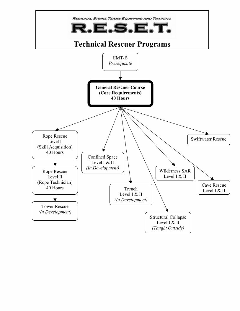
EMT-B
Prerequisite
General Rescuer Course
(Core Requirements)
40 Hours
Rope Rescue
Level I
(Skill Acquisition)
40 Hours
Rope Rescue
Level II
(Rope Technician)
40 Hours
Confined Space
Level I & II
(In Development)
Trench
Level I & II
(In Development)
Tower Rescue
(In Development) Structural Collapse
Level I & II
(Taught Outside)
Wilderness SAR
Level I & II
Cave Rescue
Level I & II
Swiftwater Rescue
Technical Rescuer Programs

1 of 8
SRT (03/09/2009) C. Jenkins Revised (07/16/2009) C. Jenkins Revised (Mc) 1/1/11
Level I Rope Rescue Course
(Rope Technician) Class Title: SRT (Single Rope Techniques) NFPA 1006/RESET JPR’s: NFPA 6.1.3, 6.1.5, 6.1.6 RESET 1.7 Time: 6 hours Scheduling Suggestions: SRT skills will take place the first day of Level 1. The 6 hour block of instruction will take place in a controlled environment on pre-rigged ropes that allow the student to be lowered if necessary. For example rope run through a high point down to a munter hitch to allow a student to be lowered to the ground if necessary. Materials/Equipment needed: 8 ropes at least 100ft , 8 20ft webbings, 8 XL carabineers, and 8 large carabineers Instructor requirements: 4 instructors Objectives: At the end of the training the rescuer should be able to:
! Define Single Rope technique, SRT ! Understand and perform safety checks on multiple different rescuers ! Choose proper equipment and descend a fixed rope ! Employ techniques for self rescue from a jammed descender ! Identify a frog system ! Troubleshoot problems in his or her frog system ! Ascend a fixed rope at least 30 feet ! Change over from climbing to rappelling using a frog system ! Change over from rappelling to climbing using a frog system ! Understand and define the dangers of Harness Hang Syndrome

2 of 8
SRT (03/09/2009) C. Jenkins Revised (07/16/2009) C. Jenkins Revised (Mc) 1/1/11
SRT (Single Rope Techniques) Single Rope Techniques (SRT) are fairly new to the Fire Service side of rescue. SRT however is not new to the rescue world. Cave and Cliff teams all over the United States have been using SRT for 30 plus years. SRT means a single person can move up and down a fixed rope with nothing but the gear attached to their harness. This rescuer has the ability to rappel down to whatever area they are trying to access, and then climb out under their own power. These techniques also give us many more options when tending litters and providing help on the edge. Chapter 18 of National Fire Protection Association (NFPA) standard 1006 identifies Job Performance Requirements (JPRs) for Cave Rescuers. JPR 18.2.6 states: 18.2.6 Use single rope techniques to ascend a minimum of 30.5 m (100 ft) in free space, given an anchored fixed rope system, so that the rescuer is secured to the rope with an ascending system that utilizes at least two gripping points of attachment at or above the waist and a quick attachment safety device, the person ascending can stop at any point on the fixed rope and rest suspended by his or her harness, the rescuer can convert the ascending system to a descent system at any time, and a rescuer demonstrates a level of proficiency and fitness that allows the rescuer to continue assigned operations immediately following the ascent. (A) Requisite Knowledge. Equipment and methodology for fixed rope ascension, rigging principles, down climbing, weight transfer, knot passing, changeovers, passing re-belays, ascent-to-descent system conversion, and alternative techniques designed to cope with adverse environmental conditions and limited light sources. (B) Requisite Skills. The ability to select equipment appropriate to length of the ascent, secure harness to ascending system and fixed line, self start, ascend line, maneuver around environmental and system-specific obstacles, rest while suspended, convert the ascending system to a descending system while suspended, and complete an edge transition. It is the intent of this lesson to prepare students for this NFPA JPR. There are thousands of caves in the Central Texas area. In an attempt to prepare rescuers for all types of rescues that would use ropes, we will teach a rappelling and ascending technique that will work well for various aspect of rope rescue including cave rescue. The specific technique taught will give the rescuer great flexibility regardless of environment. These environments including: buildings, industrial plants, cliff sites, caves, drainage ditches, etc. IMPORTANT: Due to the nature of SRT it is important that we utilize the ON ROPE and OFF ROPE commands to ensure everyone around the rope in use, understands your rope is in use. These commands coupled with our standard operating procedure, which says
3 of 8
SRT (03/09/2009) C. Jenkins Revised (07/16/2009) C. Jenkins Revised (Mc) 1/1/11
no rope will be untied from its anchor until pulled up and over the edge, will assist in keeping our work areas safe. Also, when performing SRT skills during the confines of RESET training, a bottom belay will be used. If conditions do not allow a bottom belay, individuals performing SRT skills will be tied in short. Any exceptions must be approved by the lead instructor.
Your Ascending and Descending system: Frog System The Frog system is made up of 9 key components:
! Seat harness (cave or wilderness harness recommended (Must be third party labeled)
! Chest harness designed for frog climbing (Tied or Pre-Fab) ! Chest croll ! Upper ascender (handle ascender, Basic, etc….) ! 1 Foot loop strap attached to the bottom of the top ascender ! 1 Safety strap attached from the harness to the bottom of the top ascender ! 1 set of Cow’s tails pre-fab or made from dynamic rope ! 1 QAS (quick attachment system) ie prussic or other device ! Mini Rack
These components put together in the correct order create a frog system. The QAS listed above refers to a device that the rescuer may attach to the rope quickly in the event of a problem or need to self rescue. It will also be used for passing knots while climbing rope. There are several devices that can be used as a QAS for example: another handle ascender, prussic, basic, etc. The QAS gives us options as a SRT rescuer and is very helpful when you find yourself in an unexpected situation on rope. Below, is a suggested organization of the frog system on a SRT mallion of individual. View taken as the rescuer is looking down at his maillon (a.k.a. seat harness half round).

4 of 8
SRT (03/09/2009) C. Jenkins Revised (07/16/2009) C. Jenkins Revised (Mc) 1/1/11
Rescuer Personal Protective Equipment Personal Protective Equipment (PPE) for various activates aid in protecting a person from hazards associated with that activity. PPE as it pertains to firefighting, EMS work, are often written in standard operating procedures and in state and national standards. Below is a list of PPE for a technical rescuer. This list does not include all of the equipment that would be carried by a rescuer but at a minimum he or she should be equipped with:
Safety Equip
1. Helmet (Must have interior suspension system designed for impact) 2. Gloves 3. Boots with optimal ankle support 4. Helmet light (redundant helmet light sources help in times of primary light
failure)

5 of 8
SRT (03/09/2009) C. Jenkins Revised (07/16/2009) C. Jenkins Revised (Mc) 1/1/11
Additionally, equipment that may be helpful for the rescuer that may or may not be issued by the rescue team includes:
o First aid kit o Several carabineers o Piece of webbing o Food o Water o Fire starting material o Provisions for inclement weather (rain, cold, heat) o Sun screen o Navigational products (maps, compasses, GPS) o Communication medium (radios, phones, signal mirrors)
Safety Check / Buddy Check A proper safety check must be performed on any person who is getting on rope. The rescuer must have full PPE before they get on rope full PPE consists of the following:
! Helmet ! Gloves ! Complete ascending system ! Lights when necessary ! Eye protection when necessary
When checking your buddy you must first understand the equipment her or she is using, if you do not know how the equipment works, you are not qualified to safety check that person. You should make sure all buckles are secure and or doubled back if necessary. All carabineers and screw links are tightened down. The rescuers harness should be tight and fit snugly to their body. Other Devices As mentioned earlier, we will be using the mini-rack as our primary decent device; however, there are several other devices on the market such as: an 8 plate, Petzel Id, gri-gri, long frame 6 bar rack, and bobbin. These devices are absolutely safe in the hands of a trained user. It is important though to understand how the manufacturer intended that device to be used. We will teach you to operate the mini-rack effectively while performing SRT skills. Most of the skills we will teach can be used with other devices, but it is paramount that you fully understand how your device works and its application in the ever evolving environment that is rope rescue.

6 of 8
SRT (03/09/2009) C. Jenkins Revised (07/16/2009) C. Jenkins Revised (Mc) 1/1/11
Harnesses Only commercially sewn, labeled harnesses are acceptable for a rescuer. Homemade harnesses or tied harness are emergency harnesses and should only be used as such. Many harnesses tested to NFPA standards are large, bulky, and made to fit a large range of body sizes with one harness. These attributes make it difficult for rescuers to size and fit a harness for their personal use. Climbing systems used with these harnesses are usually inefficient due to the design. There are many harnesses on the market designed specifically for the climbing systems we teach and will greatly increase the efficiency of the rescuer. Greater efficiency equals safer systems. These harnesses are also tested to safety standard, usually those developed by Union Internationale Des Associations D’Alpinisme (UIAA). In the 1960’s the US Air Force did a round of testing to determine the effects of parachute harnesses on the human body. The end product essentially stated that forces over 12kN are dangerous and will possibly cause damage to the human body. This 12 kN force is used in the design of equipment including: carabiners, dynamic ropes, harnesses, etc. The NFPA 1983 test standard for harnesses is both a 22kN slow pull test plus a dynamic drop test of fall factor 1 of one meter with a 300 lb test dummy on a cable. The UIAA test standard for harnesses is a 15kN static load for five minutes or more. Both standards require that the harness be capable of sustaining a force above that which the Air Force determined to be dangerous to the human body. It is the opinion of RESET that harnesses meeting either standard are acceptable for rescue use. Additionally the use of harnesses tested to UIAA standards are often more suited for SRT by allowing the equipment to be better fitted to the user. Descending / Rappelling A rescuer must choose the proper decent device to make the rappel. The mini-rack will be primarily used for the purposes of this class. Although there are several devices available for use, during RESET Level 1 & 2, we will focus on using the mini-rack. Keep in mind rigging high will assist you in making a smooth edge transition. Key points to remember:
! Commands – “On Rope” & “Off Rope” loud and clear ! Mini rack must be properly reaved before the rappel ! The student must be safety checked by another student or an instructor prior to
approaching the edge ! The student should plumb there decent device to the edge and lock it off ! He or she should then crawl out over the edge and weight their device, then
unlock and begin rappelling ! While rappelling the student will maintain a slow smooth rappel to ensure their
safety, this will also ensure no undue stress on the equipment

7 of 8
SRT (03/09/2009) C. Jenkins Revised (07/16/2009) C. Jenkins Revised (Mc) 1/1/11
Change Over Change over is one of the most important skills in the SRT skill group. A rescuer will perform a change over when he or she needs to go from climbing, to rappelling or vice a versa. If the frog system is not properly adjusted to the rescuer or the rescuer is not proficient in changing over the rescuer may get stuck on rope. Changing over can be done in a step by step process that with regular practice can be done efficiently. These techniques will also allow the rescuer to maintain two points of attachment to rope while climbing and changing over. This process is as follows. Summary of how to Change Over from Rappel to Climb
! Stop your rappel and lock off your decent device ! Attach your top ascender above your decent device ! Then step up into your foot loop while simultaneously attaching your chest croll
above your locked off decent device but below your top ascender ! Once you have verified that your weight is transferred to the ascending system
you may unlock and remove your decent device from the rope and begin climbing Summary of how to Change Over from Climb to Rappel
! Stop climbing ! Without removing your top ascender thumb it down the rope until it is approx 3in.
above your chest croll ! Then attach your decent device to the rope as close as possible to the bottom of
the chest croll and lock it off ! In one motion step up into your foot loop and remove your chest croll from the
rope allowing your weight to load your decent device ! Then once again thumb your top ascender down the rope until it is approx 3in
above your decent device ! You will then unlock your decent device and verify it is properly rigged before
removing your top handle ascender ! Remove your top ascender and rappel
Summary of how to Down Climb When climbing rope you will sometimes need to stop and climb back down a few feet. Rather than doing a changeover, the rescuer can just down climb. Down climbing is fairly simple, but you can inadvertently put yourself in danger if not done correctly. Follow the steps below to down climb:
! Stop climbing, Move your handle ascender down approx 4 in above your chest croll
! Step up into your foot loop, simultaneously releasing the cam inside the chest croll from the rope
! You can do this by pushing the cam down from the top side of the chest croll ! While the cam is released the slide your weight down the rope allowing the chest
croll to travel with you ! Next bump your handle ascender down and repeat the process

8 of 8
SRT (03/09/2009) C. Jenkins Revised (07/16/2009) C. Jenkins Revised (Mc) 1/1/11
It is important that you only push the cam down from the top, if you release the croll or handle ascender completely you could be putting yourself in danger, because you will only have one point of attachment which exposes you to more risk while on rope. Self Rescue While you are rappelling it is possible to get stuck on rope, this may be caused by a jammed descender. A good rescuer should know how troubleshoot this problem. Option 1:
! Attach your large prussic to the rope, triple wrap, and if need a second prussic girth hitched to the first, above the descender. Now step up into the prussic loop so the you weight the prussic and free the jammed decender.
Option 2: ! Attach your climbing system to the rope above the jammed descender and step up.
You will able to free the jammed descender with your weight off the descender..
Harness Hang Syndrome Harness Hang is very real and life threatening condition. Harness hang can occur when a victim or rescuer stays motionless while in a harness for an undetermined amount of time. The medical issue is similar to that of a crush injury. The leg loops create tourniquets on the person’s legs restricting blood flow. You may see venous blood pooling in the extremities. The patient may also show signs of being shock such as low blood pressure and elevated heart rate. This poor perfusion allows toxins to build up in the lower extremities. When this person is taken off rope the sudden blood flow causes these toxins to be pushed through the body’s circulatory system unchecked in higher concentrations than the body is used to. This in turn can cause cardiac arrest.
! Have ALS personal on scene with the proper treatment un-weighting the patient’s harness
! Have patient transportation to definitive care set up and waiting
1 of 9
Patient Packaging 7/15/2007 (DJ) 6/8/09 (WM)
(Mc) 1/1/11
Level I Rope Rescue Course
(Skill Acquisition)
Class Title: Patient Packaging
NFPA 1006/AFD JPR’s: NFPA- 5.3.1, 5.3.2, 5.3.3
RESET- 1.16
Time: 1 Hour
Scheduling Suggestions: Before Field Work
Materials/Equipment needed: Ferno
Stokes
Sked
Big Wheel
Oregon spine splint (OSS)
Life Safety Products (LSP) Half-back
6 – 20’ Webbing
3 – 15ft webbing
Med Bag:
3 – 8X10 Tarps
3 - Blankets
O2 bottle (empty)
Bandaging and splinting equipment
Safety glasses
BP cuff, Stethoscope
Traction splint
3- backboards
1 – C-collar
Instructor requirements: 1:10 Instructor to Student Ratio
Objectives:
At the end of the lesson the rescuer should be able to:
! Define patient packaging
! Identify medical considerations when packaging a patient for transport
! Identify 5 patient packaging devices used in our system
! Demonstrate injured patient packaging in a Ferno
! Demonstrate injured patient packaging in a Stokes
! Demonstrate injured patient packaging in an OSS
! Demonstrate injured patient packaging in a Sked
! Demonstrate the rigging of vertical and horizontal litter bridals for the SKED
! Demonstrate injured patient packaging in an LSP
! Identify what device may be most appropriate for a pelvis injury
! Identify special considerations in patient packaging (heat, cold, wet)
! Identify and demonstrate two hasty harness techniques on a patient, Hasty Loop
and Tickner Harness

2 of 9
Patient Packaging 7/15/2007 (DJ) 6/8/09 (WM)
(Mc) 1/1/11
Patient Packaging Patient packaging is the preparation of an injured person for transport. Its purpose is to
protect the patient from further injury and exposure during evacuation, provide for their
comfort to the extent feasible, and to facilitate evacuation by making the patient easier to
handle and carry.
Medical Considerations Technical rescues are “Medical operations with technical intervention”. We are often
responding to assist someone because they are having some sort of medical issue. It is the
goal of the rescue personnel to attempt to provide the same level of care for people in
special rescue situations as those found on the street corner. Remote environments often
prevent this from occurring. It is up to the rescuers responding to provide the best
medical care possible with the given conditions. Often this involves “wilderness
medicine” or “extended medical care” approaches; improvised medical techniques with
the tools available. Rescuers should evaluate their area of response and determine the
types of medical equipment they will need. If there are multiple patients, triaging those
patients and providing care to the ones that need it most. Since patient care is critically
important and difficult in technical rescue, practice is essential. We will perform full
patient packaging and care during every scenario. Here are some medical
considerations to highlight and address when we are packaging patients for transport:
Patient monitoring
! Level of consciousness
! ABCs
! Vitals (Pulse, Respiration, Blood Pressure, Temperature – axial , rectal)
Access
! Eating & drinking (use IVs to keep patient hydrated)
! Adjustment of dressings
! Adjustment of splints
! Adjustment of padding
! Removal/replacement of wet/soiled materials
Considerations of prolonged immobilization
! Pain at pressure points
! Need to move
! Restriction of breathing
! Urination & bowel movements (catheters)
Other medical considerations
! Suspected spinal injuries require that the patient's head, neck and body be moved
as a single unit.
! Long bone fractures and large joint dislocations may keep arms and legs from
being positioned in the normal position. The injured limb will need to be
supported in an improvised way.
! The patient's normal body temperature needs to be maintained/managed.
! Prevent hypothermia
! Prevent hyperthermia

3 of 9
Patient Packaging 7/15/2007 (DJ) 6/8/09 (WM)
(Mc) 1/1/11
! Package patient to keep them warm and dry (Wrap in blanket and then in a
tarp, ensuring that airway and vitals can still be assessed)
! Use heat and cold packs when necessary
! Protect patient from exposure to the sun
! Use blood pressure cuff to maintain flow of IVs
! Secure O2 cylinder (many times between the legs of the patient)
! Use saran wrap for waterproof wound dressing
Padding void spaces
! Reduces pressure on skin surface that contact litter/lashing
! Head
! Shoulders
! Buttocks
! Groin (harness)
! Fills voids at natural curves of body
! Neck
! Lower back
! Behind knees (prevents hyperextension)
Face Protection
! Face shield
! Safety glasses
! Goggles
Helmet
! Offers minimal additional protection when patient is in litter
! May be source of discomfort
! May flex neck (compromise airway and/or C-spine alignment)
Transferring Patient to EMS
! Keep pertinent patient information and a log of vitals with the patient for
extended evacuations. A strip of tape on the basket, leg, chest, etc… may assist
with this
! One person assigned to monitor the patient and to provide a patient report to EMS
or ED
!
Devices There are many devices on the market that are used to package patients for transport
during technical rescues. Below are some of the common ones used in our system:
Ferno
! Plastic shell with a steel bar around the outside for support
! Can be slid easily over terrain
! Can be used for vertical or horizontal litter orientation
! Can be used with the big wheel (Is not the preferred choice but can be used)
Stokes
! All steel with chicken wire and wood bottom
! Is the best choice for use with the big wheel
! Provides better back protection for the patient
! Can be used in vertical or horizontal litter orientation

4 of 9
Patient Packaging 7/15/2007 (DJ) 6/8/09 (WM)
(Mc) 1/1/11
Sked
! Is best used in conjunction with the Oregon Spine Splint (OSS)
! May be medically indicated for patients with pelvis injuries, tighten down to use
as a compression splint
! Can be squeezed through tight spaces
! Is great for cave rescue and confined space
! Can be used for vertical and horizontal litter orientation
Oregon Spine Splint (OSS)
! Is used for spinal immobilization (stabilization)
! Very similar to the Kendricks Extrication Device (KED)
! When used with a hasty harness a patient can be hauled or lowered
! Is made to be used with the Sked
Life Safety Products (LSP) Half-back
! Used for spinal immobilization (stabilization)
! Can also be used without aluminum spine board
! Is made with built in attachment points for loading
Securing the Patient Stations should be setup to allow all students to package patients in each device until it
appears they can competently do so.
Ferno and Stokes
If spinal immobilization is indicated secure the patient in the spinal immobilization
(stabilization) device, then place them in the litter.
! Use two 20’ (min. length) webbings
! Tie an overhand loop in the end just large enough to go over patients foot (try to
leave footwear on)
! Put loop over patient’s foot, to act as a stirrup, and tie a clove hitch or girth hitch
around the rail to isolate the stirrup.
! Do the same on the other side
! Lash patient in the litter much like shoe lacing, securing the patient in three places
(one “X” to keep lower extremities in, one “X” around the pelvis, and one “X”
around the torso)
! Finish the lashing over the torso forming a “V” OR if required to hold the chest in
place, the lashing may be finished strait across. Care must be taken not to
compromise the airway.
! Secure the lashing with a truckers hitch on both pieces webbing independently.
Tie off the truckers hitch with a half hitch, safety it with an overhand knot. (The
same as the munter hitch)
! If the patient has lower extremity injuries that would contraindicate stirrups use
and upper “V”
! Use a 15’ (min. length) of webbing
! Preferred to put a “for real” manufactured harness on the patient
! Girth hitch the middle of the webbing on the frontal attachment on the harness

5 of 9
Patient Packaging 7/15/2007 (DJ) 6/8/09 (WM)
(Mc) 1/1/11
! Extend the two ends on the webbings upward toward the patients head and trucker
hitch the two ends to support the patients weight solely in the upper “V”, secure
the truckers hitch with a half hitch on a bight and an overhand knot
Only use the upper “V” if there are lower extremity injuries. Suspending a patient in the
upper “V” in a harness can induce the onset of Harness Hang Syndrome. During this
course no one should be suspended in the upper “V”.
Litter Bridals will be covered in the Hauls and Lowers Class
OSS
! Secure the OSS on the patient per the manufactures recommendations
! Secure the chest straps first (straps are color coded)
! Secure the abdominal straps
! Secure the ishial (leg) straps
! Secure the head
! Torso straps can go across the chest to match their color coding or can be secured
around the shoulder in case of a clavicle injury
Sked
A patient with a Pelvic injury may require being packaged in a Sked. The Sked can be
used to splint the pelvis. If a Ferno is the preferred extrication device it may be preferable
to splint the patient with a Sked and package in a Ferno. A good practice is to prepare the
packaging device before sending it to the rescuer. For example, rig the sked with the
vertical bridle prior to sending it to the rescuer.
! It is preferred to have the patient in an OSS (with shoulder board) or on a
backboard
! Attempt to leave patients footwear on to protect the patients feet
! Place the patient on the Sked with shoulders about even with grommets through
the middle of the Sked
! Cinch straps straight across the device (do not make “X’s” as they are not
recommended by the Mfg.), keeping in mind airway concerns (overhand knots on
the straps are NOT recommended)
! Bring the foot flap up and run straps through associated grommet and cinch down
(overhand knots on the straps are NOT recommended)
Vertical Bridal
! Find the middle of the 10mm vertical bridal rope and tie a butterfly or a figure
eight on a bight at the middle point of the rope
Note: directions are given with one working end of a rope both sides will mirror each
other
! Pass each end of the rope through the grommets at the head end, from outside to
inside, and pull the knot up against the top of the sked.
! Feed straight through next set of grommets , inside to outside.
! Continue to feeding rope through the carrying handles and unused grommets
(weave the rope in and out of unused grommets in-between the carrying handles).
! Pass the rope, outside to inside, thru the next grommet past the last set of carrying
handles

6 of 9
Patient Packaging 7/15/2007 (DJ) 6/8/09 (WM)
(Mc) 1/1/11
! Pass the rope ends thru grommets at the foot end of the Sked (inside outward) and
ensure the ends are even. Tie a square knot at the outside foot end of the Sked
! Extend the tails up toward the patient’s knees and pass the ends through the
litter’s bridles and tie a square knot with safeties above the patient’s lower legs.
SEE ATTACHED SKEDCO SKED INSTRUCTION FOR PICTURES
Horizontal Bridals
! Using the yellow straps provided pass them trough the slots cut in the plastic that
are angled
LSP (Half Back)
! Place around the patient and connect buckles to their respective connectors
! If being used for vertical lift, attach the spreader bar or use webbing to improvise
a harness to attach to the front vertical attachment points. Webbing should not
allow a cinching action across the patient’s chest.
Big Wheel
! Can be placed on the Ferno or the Stokes but fits best on the Stokes
! The key is to push down on the litter and not pull up
! Eases the difficulty of extended walk-outs
Hasty Harnesses
Rescuers may encounter instances where they need to remove victims from hazardous
environments quickly. Moreover, patient’s medical conditions may require expeditious
removal from the surrounding environment to awaiting advanced medical care. The
hasty loop harness and the Ticknor harness are two such harnesses that allow rescuers a
means to facilitate patient movement. Remember, these harnesses DO NOT provide c-
spine support.
7 of 9
Patient Packaging 7/15/2007 (DJ) 6/8/09 (WM)
(Mc) 1/1/11
The Hasty Loop
A rescuer can use a 20’ to 24’ piece of 1” tubular webbing. This harness can be used in
conjunction with other short spine immobilizers (e.g. OSS). If patient is unconscious
rescuers should be cautious as to not obstruct airway. A C-collar may be used to prevent
an unconscious patient’s head from flexing down or extending backwards.
Tying a Hasty Loop when the patient is standing:
Step 1: Tie a water knot in the ends of a 20 ft to 24 ft piece allowing
4”-6” tail.
Step 2: Drape bight of webbing over rescuer’s shoulder and across the rescuer’s chest
allowing 3 ft in front of rescuer.
Step 3: Bring bight of webbing underneath patients legs up to where the knot is high
center of patient’s back under their shoulders. The webbing is split with a
loop of webbing underneath each of patient’s armpits and underneath their groin.
Step 4: Pull the loops up and out to tighten. While keeping tension, gather all
pieces of webbing above the patient’s head and clip in a carabineer.
Step 6: Keep tension on the webbing till the harness is loaded with patient’s weight.
Ensure the webbing is running high across the patient’s back.
Tying Hasty Loop when patient is lying down, (ensure patient is supine)1:
Step 1: Tie a water knot in the ends of the webbing allow 4”-6” tail (sic)
Step 2: Place loop of webbing around supine patient so they are encircled.
Step 3: Move webbing underneath patient’s back where the webbing is under the
patient’s shoulders, along patient’s side and under their armpit.
Step 4: Bring a bight of webbing through patient’s legs and pull slack toward patients’
head. Lay webbing flat across one of patient’s shoulder next to patient’s head .
Step 5: Grasp webbing at patient’s side and bring upward to form loops on each side of
patient. Capture all webbing loops above patient and clip a carabiner into it.
Step 6: As the harness is tensioned, assist the patient to a sitting position. Ensure the
harness is secure and the webbing is high across the patient’s back running
underneath the patient’s armpits.

8 of 9
Patient Packaging 7/15/2007 (DJ) 6/8/09 (WM)
(Mc) 1/1/11
Ticknor Harness:
The Ticknor harness can be tied with attachment loops on the back (for confine space
removal) or loops on the front (preferred method for conscious patient). Rescuer’s can
use a 30 ft piece of webbing to tie the Ticknor:
A Patient can be standing or lying down.
Step 1: Find middle of piece of webbing and place behind patient back. Run each end of
webbing underneath the patient’s armpits Grab the running ends of webbing and
make two bights with the webbing on either side of patient’s armpits.
Step 2: Tie a square knot with bights of webbing above the nipple line of the patient.
Clip bights of webbing with a carabineer, ensure to keep the carabiner above the nipple
line while finishing the harness.
Step 3: Run webbing down in front of patient’s chest down through patient’s legs, do
not cross. Bring ends up behind patient’s buttocks around to the front.
Step 4: The right side webbing end will go underneath the right side
webbing in front of the pelvis back towards the patient’s rear. The left side
webbing end will go underneath the left side webbing in front of the pelvis back
towards the patient’s rear.
Step 5: Start wrapping the pelvic girdle. Allow at least 12-18 inches of tail to tie a
square knot with safeties on either hip.

9 of 9
Patient Packaging 7/15/2007 (DJ) 6/8/09 (WM)
(Mc) 1/1/11
Step 1 Step 2 Step 2
Step 3 Step 4 Step 5
Step 5 Step 5
Tickner Harness

1 of 4
System Safety Factors 7/12/2008 (DJ)
Level I Rope Rescue Course
(Skill Acquisition)
Class Title: System Safety Factors
NFPA 1006/RESET JPR’s: RESET- 1.13
Time: 1 Hour
Scheduling Suggestions: Early in the course
Materials/Equipment needed: NA
Instructor requirements: 1:30 Instructor to Student Ratio
Objectives:
At the end of this lesson the rescuer should be able to:
! Explain what a Safety Factor is
! Define Minimum Breaking Strength (MBS)
! Identify factors that can affect Minimum Breaking Strengths (MBS’s) of different
components
! Identify and explain force multipliers
! Identify and explain two types of safety factors
! Identify the target Static System Safety Factor (SSSF)

2 of 4
System Safety Factors 7/12/2008 (DJ)
System Safety Factors Safety factors are often misunderstood in the technical rescue community. There are
many misconceptions about safety factors. This lesson will attempt to clarify the safety
factor concept and how they apply to RESET.
A “Safety Factor” is basically a ratio of a minimum breaking strength to a load or force.
The term force is more appropriate to use as forces at points in rescue systems can often
be greater than the load.
Minimum Breaking Strength (MBS) Now we must define MBS and determine how that MBS was determined and if and how
that figure applies to a given situation. Often our rigging methods will affect the MBS.
MBS is simply defined as the component strength. That strength is determined using very
specific testing methods. Sometimes the test method is made up by the manufacture of a
device to test the device in its manner of use. Other times, the test method is dictated by
standards (i.e. NFPA, ASTM, UIAA, etc). In either case, if done properly, the test should
be consistent and reproducible. Most often this is done in a scientific lab type setting.
What is important for end users is how our rigging methods may produce different
breaking strength compared to those published by manufacturers. For example, a
carabiner is tested with one inch pins on both ends of the carabiner. The pins are pulled
apart to load the carabiner along its long axis and are pulled at a very specific rate. This is
not how carabiners are used in the field. So we as rescuers need to know how our use of
that carabiner will change the published breaking strength (i.e. 3 way load- strength
reduction of 30%, side loading- strength reduction of 70%).
Other examples of affected MBS Factors affecting Carabiners:
! Age
! Material
! Loading axis (short axis around 70% strength reduction)
! Three-way loading (around 30% strength reduction)
! Environmental exposure
! Double loop knot (around 20% strength reduction depending on type of carabiner)
Factors affecting Rope:
! Age
! Condition
! Diameter
! Knots (around 30% strength reduction)
! Manufacturer
! Sharp bend in the rope (over edges)
! Water (around 15% strength reduction)

3 of 4
System Safety Factors 7/12/2008 (DJ)
It is paramount that rescuers know their equipment. Know the type, brand, manufacturer,
MBS, and factors affecting MBS of all the equipment in your cache.
Rigging Technicians must understand the effects of rigging and how it can affect the safety of
their systems. Forces produced by the load can vary greatly depending on how things are
rigged. An example of that is force multiplication. There are two common types of force
multiplication:
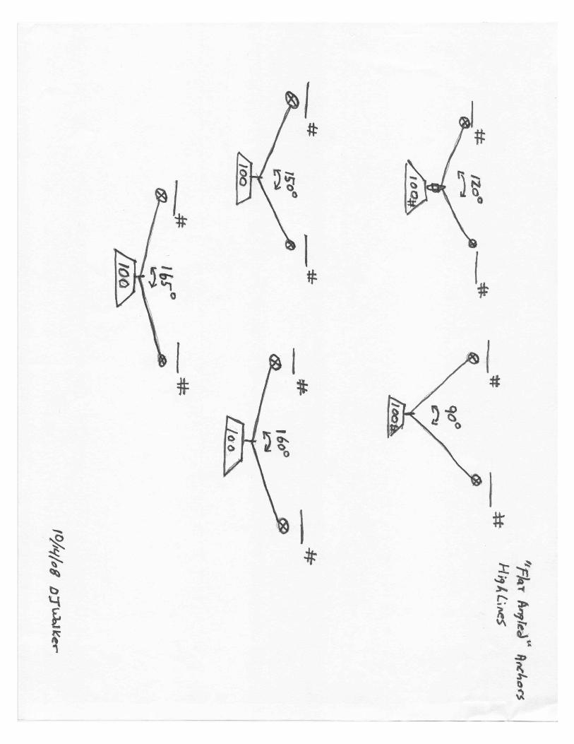
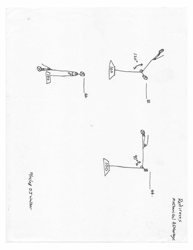
1. Those found in highlines and “flat angled” anchors
2. Those found in mechanical advantage and deviations (redirects)
Both of these must be understood to allow accurate calculation of safety ratios. Once we
can identify force multipliers, we can identify the force applied to different components.
Static System Safety Factor Historically the term Safety Factor has been used. In reality, this “Safety Factor” is a
ratio. So we will continue to call them Safety Factors with the understanding it is really a
ratio. There are two types of safety factors/ratios:
1. Component-to-Force Ratio
2. Static System Safety Factor (SSSF)
Component-to-Force Ratio
A given piece of equipment does not, by itself, have a safety factor. It must first have a
load or force applied to it. As stated above rescuers should be extremely familiar with the
MBS of their equipment. Once the MBS and the load /force are identified the rescuer can
calculate the Component to Force Ratio.
MBS:Force/Load
Various examples of Component-to-Force Ratios should be discussed.
Static System Safety Factor
As with a single component, a system does not have a given safety factor. The rescuer
must asses the system and determine the Static System Safety Factor (SSSF). This is
done by identifying the component with the lowest Component-to-Force Ratio (the
weakest link). Once the weakest link is identified this becomes the SSSF.
WL-MBS:Force/Load
Several examples of systems should be provided and the SSSF of those systems
determined.
What is an acceptable SSSF? This is dependant on a variety of factors. (i.e. Is the load
going to stay static? Is there a possibility of an impact force? Was the original SSSF
correct? Is there a side-loaded carabiner? etc) We use the term Static System Safety
Factor because we are calculating this ratio with the system not in motion. Any increase
in force from acceleration, impact forces, or other noise in the system would be

4 of 4
System Safety Factors 7/12/2008 (DJ)
accounted for by keeping our ratio large enough. So again the question is: what is an
acceptable safety ratio?
Typically, we try to target a 7:1 SSSF. It may not always be obtainable, but this is a
good ratio to shoot for. If we do not meet a 7:1; we must decide if it is enough for the
task. The reality is that anything above a 1:1 should hold. But 1:1 does not take into
account other “noise” in the system that we did not account for (wet rope, extra friction,
increased load, dynamic event, etc), so we choose to use a larger ratio to account for the
unknowns. Use equipment appropriately and use rigging methods that keep forces to a
minimum, or rig to account for those higher forces. We want rescuers to rig intelligently
and with insight.
Human Factor What is the safety factor on your judgment? We can build the strongest systems possible
and issue the best equipment available but it is still up to us to use them correctly. We
have to pay attention to our systems. Watch for load shifts, tie knots properly, stay
attentive while belaying, etc. Any piece of equipment or standardized practice can be
unsafe if you make it unsafe. Know you equipment and how to use it.
Is Safer Actually Safer? At times when attempting to make a system hyper-safe it is possible to make a system
that is impractical or inefficient to the point of being dangerous. It is in the nature of
firefighters to add more. More of everything is better, right? Not necessarily. Two belays
should be better than one, right? NO!! If everyone on the scene cannot walk up to your
rigging and identify they system and its purpose, or if you cannot explain it without
hesitation, maybe it is too complicated. Sometimes complex systems are needed but try
not to over-engineer. A simple axiom to remember is: When redundancy begins to affect
efficiency safety is compromised. Rescuers should build systems that provide reasonable
safety margins while maintaining efficient and effective rescue systems.

1 of 5
Belay Systems 7/4/2007 (DJ) 8/09 (Adam) 2/2011 (DJ)
Level I Rope Rescue Course
(Skill Acquisition)
Class Title: Belay Systems
NFPA 1006/AFD JPR’s: RESET 1.10
Time: 1 Hour
Scheduling Suggestions: Before any technical work is done
Materials/Equipment needed: 4 Groups:
4 – 100ft+ ropes
10 – 15ft+ webbing
4 – Single Prusik Minding Pulleys
4 – XL Carabineers
10 Carabineers
4 – Jigger - 2 Micro Prusik Minding Double Pulleys, 35’ of 9mm rope, 6mm prusik loop for progress
capture
4 – Tandem Prusik
4 – Radium Load Releases (LRH) 33’ of 8mm accessory cord, 2 carabineers
Instructor requirements: 10:1 Student to Instructor Ratio
Objectives:
At the end of the Training the rescuer should be able to:
! Define belay systems
! Describe four common categories of belay systems
! Identify two types of top belays
! Describe seven characteristics of a tandem triple wrapped prusik belay
! Demonstrate tying a Radium Release Hitch
! Identify eight considerations of top belays
! Build and operate a Tandem Triple Wrapped Prusik Belay
! Recite the belay commands

2 of 5
Belay Systems 7/4/2007 (DJ) 8/09 (Adam) 2/2011 (DJ)
Belay systems Belay Systems are defined as systems employed to safeguard the load in the event that
the main means of supporting it is rendered ineffective. Some examples of that would be:
damaging equipment, human error, etc…. It is common to attempt to have two ropes
attached to a load when being supported by rope based systems. Sometimes this is by
means of a “Two Tensioned Rope System” (two mainline systems attached to the load)
other times this is done by means of a single tensioned main-line and an un-tensioned
belay line. There are many methods for belaying a load and belays may not be required
100% of the time, though it is common to belay most loads. It is paramount, if a belay
system is utilized, that it be able to safeguard the hazard in which it was designed to
belay. Often this means that the system be required to arrest an impact force from a
falling load. Here are some categories of belay systems:
Self Belay
This is when methods are utilized to safeguard yourself. Some examples of this would be:
! Attaching to a local anchor
! Tending a friction hitch (attached to the same rope that is supporting you or to a
separate rope) during a rappel, raise, or lower
Lead Belay
This system is typically used in “bottom up” rescues (towers, taller rock walls with no top
access, etc…) The climber climbs up and periodically places intermediate anchor points
and attaches a rope to them. With this type of belay high Fall Factors may be produced
and in turn high impact forces can be present. This is why dynamic rope is often the best
choice for lead belay systems.
Bottom Belay
This is when someone is at the bottom of a fixed rope rappel or traveling break lower.
Their job has two parts:
1. Pull down on the rope, to act as the break hand for the descender
2. Pull the end of the rope away from plumb so as to make the distance from the
load to the “Bottom Belayer” further than the distance from the load to the
ground, making it next to impossible for the load to reach the ground.
Top Belay
This is the most typical type of belay employed in rescue. This is accomplished by
attaching a redundant un-tensioned rope to the load that is run through a belay device.
This rope is generally left unloaded during an operation and only utilized in the event that
the main load supporting system is rendered ineffective. Often when this belay is actuated
the load produces an impact force on that rope and belay system. Great effort should be
made to ensure that the belay method chosen is capable of arresting that impact force.

3 of 5
Belay Systems 7/4/2007 (DJ) 8/09 (Adam) 2/2011 (DJ)
Two Common Top Belay Methods
Munter Hitch Belay
(Review this belay from the General Rescuer Course)
This belay utilizes the friction from the Munter hitch (often called the Italian hitch) to
arrest the impact force produced by the load. Munter hitches are typically used for lighter
loads (<300 lb) but if tended correctly, and a moderate amount of edge friction is present
to absorb some of the impact force, it is possible to belay heaver loads (<600 lb). This
belay does require the belayer to maintain control of the brake rope in order for this belay
to be effective. Some characteristics of this belay are:
! Fast set up
! Minimal equipment
! Effective
! Requires rescuer interaction
! A Munter hitch is best used in conjunction with an XL Carabiner
! To go hands free tie off with a half hitch followed by an overhand
Parts of a Top Belay
! Anchor
! Rope
! Belay device
! Belayer
! Load
Tandem Triple Wrapped Prusik Belay (TTPB)
(Cover this belay in-depth)
This belay utilizes two prusik hitches sized, matched, and tended appropriately to catch
the impact force. This belay is a quirky belay system that requires constant maintenance.
The TTPB, if tended appropriately, is capable of arresting the impact forces produced by
heavier loads (600 lb, possibly more). Some characteristics of this belay are:
! Can be hands free for short durations
! Requires more practice operating to become proficient
! Requires that the prusiks be sized and dressed appropriately to maximize
effectiveness
! Requires rescuer interaction
! Can use PMP during a raising operation to keep line slightly tensioned
! Operation during lowering evolution: strip rope through prusiks in short bights,
never allowing more than one foot of slack to develop. Keep prusiks at 90 degree
angle to belay line’s direction of travel. Keep system components between prusiks
and anchor snug (don’t allow them to sag). BELAYING DURING A
LOWERING OPERATION IS A DIFFICULT JOB, AND MUST BE TAKEN
ABSOLUTELY SERIOUSLY.
! In the event of an actuation, the prusiks are “locked up”. There should be a plan to
overcome this. Typically a Load Releasing Hitch (LRH) or jigger is used in
conjunction with the TTPB.

4 of 5
Belay Systems 7/4/2007 (DJ) 8/09 (Adam) 2/2011 (DJ)
Load-releasing hitch
(Each student should be competent at tying the RRH)
The load-releasing hitch (LRH) can be a valuable rigging tool. The LRH is used to
release tension in a system. Some situations where an LRH can be incorporated are:
tandem prusik belay, behind a progress capture device, knot passing, high points etc… As
a rule of thumb any time a prusik has the potential to be loaded it may be a good idea to
have an LRH behind it.
There are many variations of load releasing hitches, but the most common type used is
the Radium Release Hitch (RRH). The RRH is normally constructed from 10 meters (33
feet) of 8mm accessory cord. The RRH is basically a 3:1 system with a Munter hitch
incorporated. Remember that with the RRH being a 3:1 for every foot that is load-
released it will utilize 3 feet of the excess cord. This is why it is important to be sure that
the length of cord used is adequate; which is why 10 meters is suggested. The end of the
cord needs to be managed just like any other system would be. Either tying a knot in the
end of the cord or tying the end to a fixed anchor is acceptable.
Jigger
The jigger can be used in a multitude of locations, however in this application it is used in
place of the RRH. It is not incorporated into the system like the RRH but should be built
and readily available. If needed it can be quickly attached and used for all the functions
of a RRH plus it has the ability to make short hauls.
Load Transfer After an Inadvertent Lock Up or a Belay Actuation
In the event that the prusik in a TTPB become loaded they must be released before the
rescue can continue. When using a RRH; you tension and SET the mainline, unlock the
RRH, then you perform a slow lower with the RRH until the weight of the load is fully
on the mainline. You can then release the tandem prusik and reset the RRH.
To use the jigger for the same function you will connect it to an anchor and attach it in
front of the loaded prusiks with a rope grab. Haul on the jigger until the prusiks are no
longer tensioned. Ensure the mainline is functional and use the jigger to release the load
onto the mainline.
Top Belay considerations:
! Be aware where your body is in relation to the belay system. If the rope gets
loaded where is it going to go?
! If a directional is needed, avoid using pulleys. Instead run the rope through a
carabiner to provide friction.
! Avoid running belays through high-point’s
! Rig the belay where it can be easily operated
! To keep redundancy, rig belays on separate anchor points. If an anchor point is
exceptionally bombproof the same point may be used. However students should
rig separate anchor systems for the main system and the belay system.
! Try and rig belays somewhere around 10 ft from the edge and as inline with the
main-line as possible. This will ensure adequate communication, room for on- and
off-loading, and prevent any drastic load shift in the event of an actuation
! Pad the edge if indicated
5 of 5
Belay Systems 7/4/2007 (DJ) 8/09 (Adam) 2/2011 (DJ)
! If attaching belays to a person in a harness the Belay should be attached to the
front attachment point. No belay should be attached to the dorsal or back
attachment on a harness. (The only exception would be for an emergency retrieval
system in Confined Space work)
Commands As with any operation, standardized commands can increase efficacy. Before
operating any system a “Role Call” should be conducted. The “Role Call” Command
applies to any operation (i.e. Lower, Raise, Belay etc.). A System Safety Check should be
done either just prior to the role call or finished before the role call is complete.
Before any system is used the person in charge should start the operation by
loudly saying “ROLE CALL”, followed by a ready check (role call) of each position
(i.e. brake-man, belay-man, edge tenders, haul team, tag lines, etc.).
Once the role call is complete, the command “Position the Load” should be used
to direct the team members to move the load in a position to be hauled or lowered.
Once the load is into position, the command “Load the System” will be used to
suspend the load by the ropes.
Example:
Squad Leader- “ROLE CALL” (everyone should stop talking and listen to the leader)
Squad Leader- “Blue Line Ready?”
Blue Line Operator- “Blue Line Ready!”
Squad Leader- “Red Line Ready?”… (Leader should check the readiness of all positions)
Red Line Operator- “Red Line Ready”…(All positions should respond with their
readiness)
Squad Leader- “Position the Load” (The load should move into position)
Squad Leader- “Load the System” (The load should be suspended by the ropes)
Squad Leader- “Slow Haul”, “Slow Lower”, etc. (Direct the operation)
Other Standardized Commands
! On Belay- This is a question to the belay-man to ensure he/she is ready to belay
! Belay On- Is the answer from the belay-man confirming he/she is prepared to
belay.
! Off Belay- Term used to let the belay-man know the belay is no longer needed
! Belay Off- Used to confirm the belay is no longer in operation
! Stop- Used by anyone in the operation to suspend action
! Slack- A request for slack
! Tension- A request for tension

1 of 3
Belay a Falling Load 7/15/2007 (DJ)
Level I Rope Rescue Course
(Skill Acquisition)
Class Title: Belay a Falling Load
NFPA 1006/AFD JPR’s: RESET- 1.11, 1.12
Time: 1 Hour
Scheduling Suggestions: After the students have had the opportunity to operate belay systems in the field
Materials/Equipment needed: 3 – 20ft webbing
4 half inch ropes at least 100’ long
2- double pulleys
1 – Rope grab
1 – Set of tandem prusik
1 – radium load release
1 – Single pulley
8 – large carabineers
2 – Quick release (can use 550 cord tied
between the haul and the rope connected
to load, then cut to release the load)
Minimum 440lbs of weight/ 600
preferred
Rope and equipment used to set up belay systems should be out of service or will be
taken out of service after this lesson
Instructor requirements: 1:10 Instructor to Student Ratio
Objectives:
At the end of the lesson the rescuer should be able to:
! Identify the purpose of a belay
! Describe Fall Factors
! Describe 0 Fall Factors and how it relates to rescue belays
! Successfully catch a falling load using a Tandem Triple Wrapped Prusik Belay
2 of 3
Belay a Falling Load 7/15/2007 (DJ)
The Purpose of a Belay Un-tensioned belay systems are commonly used in rope rescue operations. It is
paramount that if rescuers use an un-tensioned belay system that they ensure it will work
as intended. Often this means that it will be capable of catching an impact force. This
impact force would be produced by the rapid loading of the rope by the load that was
supported by another system.
Impact Force (AKA Shock load) - The rapid deceleration of a falling load. (like those
seen in a belay line actuation)
Be sure that the belay system selected will safe guard the hazard in which
the belay was intended to protect.
Fall Factors Fall Factors are the ratio of the distance fallen compared to the available rope slack. It is
used to portray the severity of a fall.
Distance Fallen ⁄ Available Rope Slack
When a load falls it possesses energy (kinetic energy). When the rope is shock loaded the
length of rope stretches and absorbs energy. If the energy produced by the falling load is
greater than the ropes absorption capacity, the rope breaks. So the peak force produced by
a load is dependant on how much rope is out and how elastic the rope is. The more rope
out, the more rope there is for the load to be spread over. The more elastic the rope is the
better energy absorbing ability it has. This explains why the increase in energy from a
longer fall, at the same fall factor, caused by more rope slack will correspondingly
increase elongation, thus making the percentage of rope elongation unchanged, intern
making the peak force the same.
Fall Factors in Rescue Belays The British Columbia Council for Technical Rescue has a belay competency test that is
commonly used to evaluate the effectiveness of a belay. This competency test defines a
set of conditions theorized to be the “worst case scenario”. This would include:
! A .33 Fall Factor (FF). Derived from the assumption that the belay would be
rigged about 10 feet from an edge with there being about 3 feet of slack
introduced from the belay attachment to the edge. This would be a 3 foot fall on
10 feet of rope producing a .33 FF.
! 440 Lb load
! No edge friction
! There are several other conditions that are not relevant to the topic
These set of conditions have their place but once the load is over the edge many of these
parameters change. More often than not we are rigging our belays to incorporate edge
friction. Any edge friction present will assist in absorbing the energy produced by the
falling load.

3 of 3
Belay a Falling Load 7/15/2007 (DJ)
Once the load is over the edge or it is being lowered or raised there is much effort taken
to reduce the amount of rope slack in the system.
The less rope slack = the less the load falls = the less the energy produced
When there is no rope slack in the system and the unloaded rope is suddenly loaded with
no fall occurring this is considered a 0 FF. Engineers use 0 FF for many calculations for
design requirements for bridges, buildings, etc…. The theory behind 0 FF is that it
produces twice the elongation than that of the static elongation at the given weight.
Otherwise stated: If you were to measure the length of the rope prior to being loaded.
Then statically load the rope with a specific weight and measure the length again (it will
have stretched). Compare the two measurements; this will give you the static elongation
with that weight. So in a 0 FF shock load the rope would stretch twice that distance.
So how does 0 FF relate to us? Manufacturers are now providing the static elongation of their rope at 300 and 600 lbf.
For example a PMI Nylon 12.5mm rope will stretch 1.6% at 600 lbf. Let’s round that up
to 2% for easy math. This means that for every 100 feet of rope it will statically stretch 2
feet. And at a 0 FF it will stretch 4 feet.
Another way of viewing that would be: At the beginning of a 200 feet raise, during first 8
feet of the raise the belay is essentially ineffective, because the rope will stretch so much
that the load would probably still hit the deck.
Belays do provide some security in our operations. But often the inconsistency in our
belay systems is overshadowed by the consistency of our main systems. So as we rig we
should always be rigging our main systems for success.
Catching a Falling Load During the General Rescuer Course students should have caught a falling load on a
munter hutch belay. In the Level I course students are taught the Tandem Triple
Wrapped Prusik Belay (TTPB). Each student should be given the opportunity to catch a
falling load with a TTPB using at least a 440 lb load (600 lb preferred). Allow the student
to operate the TTPB hitch for a short time; the load should be dropped onto the belay
system producing an impact force that the student would have to arrest. The rope should
run over an edge or a simulated edge such as a carabiner.
Each student should successfully catch a falling load with a TTPB.

1 of 7
IMS 4/7/11 (DJ)
Level II Rope Rescue Course
(Rope Technician) Class Title: Incident Management for Technical Rescue NFPA 1006/RESET JPR’s: NFPA- NA RESET- NA Time: 15-20 Minutes Scheduling Suggestions: Toward the end of the class Materials/Equipment needed: Instructor requirements: 5:1 student to instructor ratio Objectives: At the end of the lesson the trainee shall be able to:
! Identify the Primary Principles of the Incident Management System ! Identify the various standardized IMS terminology used in Technical Rescue ! Identify the three Incident Priorities ! Explain the L-A-S-T acronym ! Identify the three possible Modes of Operation ! Describe and use a C-A-N report when giving a size-up ! Identify Task/Tactical Level Benchmarks ! Identify Command Level Benchmarks
2 of 7
IMS 4/7/11 (DJ)
Introduction The Incident Management System (IMS) should be familiar to most rescuers who take this class. To review its primary principals:
o It is a standardized flexible format that expands and contracts to fit the needs of a given incident.
o Uses common terminology that allows rescuers from multiple organizations to work together.
o Creates a unified command structure that ensures everyone works for one leader and no tasks are duplicated (unless needed).
o Identifies an Incident Action Plan (IAP) for every incident. Sometimes these are formal and written, other times they are predetermined.
o Creates a manageable span of control to ensure no one is overloaded with tasks or personnel. Typically, one person should manage three to seven people or tasks, with five being optimal.
o Creates a comprehensive resource management plan. As reviewed in General Rescuer, the standardized format for setting up the command structure includes:
o Command Staff o Incident commander (IC) or Command- Is the leader, ultimate authority
and responsible party. o Safety Officer- Is the person designated specifically to oversee the safety
aspect of the event. In the technical rescue setting this person should have a background and several years of experience in technical rescue.
o Liaison Officer- Is the person who would interface with other people and organizations who may be involved or have a vested interest in the incident.
o Public Information Officer (PIO)- Is the person who usually should interface with any media or other group whom information about the incident is to be released.
o General Staff o Operations Chief- Oversees the operational aspect of the rescue or
recovery. o Plans Chief- Creates plans for the event including: travel plans,
accountability plans, operational period plans, etc. Additionally this chief normally runs meetings and is responsible for the overall documentation of the incident including the IAP.
o Logistics Chief- Takes care of all of the logistical needs of the incident including: food, shelter, equipment, etc.
o Finance Chief- Takes care of the financial aspects, including: tracking equipment cost, personnel cost, fuel cost, etc.
The IC will determine the format that will be used for the incident. Each IC has their own preferences for how to set up the structure and this varies with the needs of different incidents. Under a Section Chief there can be Single Resources, Groups, Divisions, and Branches. Single Resources may be given tactical assignments. Groups are responsible

3 of 7
IMS 4/7/11 (DJ)
for specific tactical functions and are lead by a Group Supervisor. Divisions are normally associated with a specific geographical area and are lead by a Division Supervisor. Branches can be created when resources, groups and/or divisions reach a number that the span of control is too large and an additional layer of management needs to the created. Branches are lead by a Branch Director. Common Terminology is one of the benefits to the IMS system. Additionally, the RESET curriculum defines terminology used by its students and instructors. The terms used by RESET were chosen in an effort to maintain consistency with other technical rescuers throughout the US. This can be as simple as specifying what to call a specific haul system or device. To better define some standardized terms, below are some IMS terminology relevant to technical rescue:
o Hot Zone- Is the area immediately around the rescue site. This is where rescuers are attached to ropes to safe guard from falling, usually identified as a body’s length from an edge or unsafe area.
o Warm Zone- This is immediately outside of the Hot Zone. The rigging is normally in the warm zone.
o Cold Zone- This is outside of the warm zone. Typically the command post and other support functions can be found here.
o Rescue Group- Is the Group that performs the rescue functions associated with a specific task. In complex rescues or rescues that span over a large area, there may be multiple Rescue Groups.
o Rescue Group Supervisor- This is the person designated to lead the Rescue Group. This person normally directs the operations of the rescue and decides how the rescue will be accomplished.
o Medical Group- Is the Group that has responsibility to provide care to the patients and rescuers.
o Medical Group Supervisor- This is the person designated to lead the Medical Group.
o Evacuation Group- Is the group charged with transporting the patient(s) from the rescue area to the ambulance or other transportation to the hospital. In complex rescues or rescues that span over a large area, there may be multiple Evacuation Groups. Sometimes the Rescue Group carries out this function.
o Evacuation Group Supervisor- This is the person designated to lead the Evacuation Group. This person normally directs the operations of the evacuation and decides how the evacuation will be accomplished.
o Hasty Team- Is a team of rescuers sent to quickly search an area or a specific point, and is lead by a Hasty Team Leader. This team should pack light and focus on speed.
o Search Team- Is a team of rescuers who are responsible for thoroughly searching an area and is lead by a Search Team Leader.
o Patient Access Team- Is the team that finds the best way to make Pt access and is lead by the Pt Access Team Leader. This is normally the first team to locate the Pt.
o Edge Team- This is the team that is be responsible for assisting at the edge and is lead by the Edge Team Leader. This team provides Edge Tenders.
o Rigging Team- Is the team designated to rig a specific technical problem and is lead by the Rigging Team Leader. This team determines the rigging techniques to

4 of 7
IMS 4/7/11 (DJ)
be used and works with the Edge Team and the Pt Access Team to determine the best litter orientation and edge solution. There may be multiple Rigging Teams for one rescue.
As the incident progresses, team or group designations may change to fit the needs of the operation. (Ex. A Search Team that finds the Pt may turn into the Pt Access Team) There are many ways to set up an ICS system. Here are a couple of examples of how they may be set up:
Incident Priorities The Incident Priorities for a technical rescue are no different that any other incident:
1. Life Safety 2. Incident Stabilization 3. Property Conservation
Strategy and Tactics All strategy and tactics should be designed with the incident priorities as the overall focus. The strategy used for technical rescue incidents should generally be categorized as one of the following: Search, Rescue, or Recovery.

5 of 7
IMS 4/7/11 (DJ)
A strategy should be developed and shall center on satisfying the following objectives. They are referred to as the L-A-S-T acronym.
o Locate- the person(s) needing assistance. This may be simple or may be a complex search.
o Access- the person(s) needing assistance. Walking, swimming, rappelling, being lowered, or other means may accomplish this task.
o Stabilize- The person(s) needing assistance. Provide medical care and package the Pt in a device that will provide the best means of extrication.
o Transport- the person(s) to an ambulance, designated area or other safe area. Modes of Operation One of the first decisions made by the first rescuers is the mode of operation. Much like fire scenes the mode of operation will be used to assign the appropriate tactics and establish a command structure. The IC should announce the mode of operation over the radio and/or ensure all personnel operating on the scene are informed. These Modes of Operation are: Search, Rescue, or Recovery Search The location of the person(s) needing help will not always be known. Locating the person(s) will be the first objective. Information gathering will assist with determining where to search. Information gathered from the 911 call taker, interviewing people on scene, talking to witnesses, use of a Lost Person Questionnaire, familiarity with the area, etc will help with gathering information. Law Enforcement is exceptionally good at gathering information and investigating the unknown. Using them in this process is usually very helpful. One of the primary focuses should be on determining the Point Last Seen (PLS). As information gathered allows you to make decisions, deploy Hasty Teams to areas where the Pt is likely to be found or other areas of interest and Search Teams to more thoroughly search areas. Search theory and tactics are outside the scope of this lesson. Please refer to lost person search tactics for more information. Once the person(s) needing help is located it must be determined if this is a Rescue or a Recovery. This decision will affect the pace of the operation and may affect the techniques used. The axiom risk a little to save a little, risk a lot to save a lot, applies. Be sure the IAP is appropriate for the mode of operation. Rescue This strategy should center on the safe and speedy removal of the person(s) from the hazardous environment. Find the best way to access the person(s). This is done by the Pt Access Team and may be by ladder, by walking around an obstacle, rappelling rescuers on single rope techniques (SRT) ropes, lowering a rescuer via a rope based system, climbing up to the person(s), or any other means appropriate. Once Pt contact is made a medical classification of the Pt should be determined and relayed to the IC/command. Next, medical care and packaging the Pt for extrication should be the focus. The Pt Access team should work with the Edge Team and the Rigging Team to determine the
6 of 7
IMS 4/7/11 (DJ)
best way to extricate the Pt including: type of litter, litter orientation, litter management (i.e. tag lines, SRT litter tenders, litter tenders on the litter, etc). As resources arrive a Rescue Group Supervisor should be established. The Rescue Group Supervisor will assign and direct a Rigging Team, an Edge Team, and will assume control of the Pt Access team. The Rigging Team should work with the Edge Team and the Pt Access Team to determine the best way to extricate the Pt. The complexity of rescue situations will not allow for specific techniques to be pre-planned. Systems built should target a 7:1 or higher Static System Safety Factor (SSSF) and not go below a 2:1 SSSF. The Edge Team should work with the Rigging Team to determine the best rigging solution to solve any edge problems or other obstacles. The Edge Team will normally employ Edge Tenders at the edge via SRT techniques. Depending on the size and scope of the incident multiple Rescue Groups may be needed. Additionally, Evacuation Groups, Medical Groups, or other types of groups may be created to accomplish the rescue. Recovery If it is determined the person(s) we are there to help is deceased, the IAP should undergo a review. There may be a need to delay extrication until Law Enforcement can conduct an investigation. The format and functions for conducting a recovery are the same as the rescue mode with the exception of ensuring the techniques are chosen with a more methodical approach. More time should be expended building systems in such a way that the most efficient method is selected. Often times the most efficient method takes more time, and therefore is not what is chosen for rescue. Size-Up Size-up is a rapid mental evaluation of the factors involved in the incident. This is a continual process and should be continuously evaluated. First arriving rescuers should provide size-ups to incoming rescuers so they can better prepare. Size up reports should provide a picture of what is happening, what you are doing to make it better and what incoming rescuers need to do. An acronym used to ensure these elements are incorporated is C-A-N, often referred to as a CAN Report. Conditions- State the current conditions. Ex. “We have a person at the bottom of a 20 foot vertical cliff. Actions- This describes the actions you or your crew is taking to make the situation better. Ex. “We are going to send a rescuer down an SRT rope to make Pt access.” Needs- Tell the incoming rescuers what you need from them to support the rescue. Ex. “We need incoming rescuers to bring rigging equipment, a ferno, and the best access to the top of the cliff is to take the walking trail by the old barn.” Size-ups or CAN reports should be given when arriving, and when significant benchmarks are met (Ex. making Pt contact, assigning or assumption of a rigging leader, determining the rigging techniques, evacuating the Pt, etc).

7 of 7
IMS 4/7/11 (DJ)
Benchmarks Benchmarks are points of reference that help measure the progress toward the achievement of the incident priorities. When assuming or being assigned a tactical assignment or function, the rescuer should announce this on the radio or ensure the ICS structure is aware of this assignment. Benchmarks can generally be grouped into two categories: Task/Tactical Benchmarks and Command Benchmarks. Here are some examples of Task/Tactical Level Benchmarks:
o Assumption or acknowledgement of an assignment (Ex. E-1 is assuming Rescue Group Supervisor)
o Completion of Assignment (Ex. Rigging Complete; Pt is packaged and ready for transport)
o Inability to complete assignment (Ex. Cannot make Pt access from the lower trail, best access is from above)
o Any significant delay in completing assignment (Ex. Pt packaging is going to take a little more time, the Pt is in a tight spot and his injuries need special attention to package in the litter)
o The need for additional resources to complete task (Ex. Need five additional rescuers for the haul team)
Command/IC should report Command Level Benchmarks for the incident record. Often these benchmarks are a part of a written IAP on a separate “worksheet”. This worksheet details the specific functions and benchmarks identified for a specific event. The following are examples of Command Level Benchmarks specific to Technical Rescue and would likely be found on a “Technical Rescue IAP Worksheet”.
o Search has been initiated to locate the person(s)- When the search has begun to locate the person(s) requesting assistance.
o Pt(s) have been located- When the location of the Pt(s) has been identified. o Pt Contact has been made- When verbal and physical contact is made. o Medical Classification of the Pt(s)- When the Medical Classification(s) of the
Pt(s) has been identified. This helps drive the pace of the operation, the need for additional resource types (Ex. STAR Flight), and gives advance notice to the receiving medical facility.
o Pt is removed from the hazard- When the Pt has been removed from the area he/she needed rescue from. (Ex. at the top of a hauling evolution, the bottom of a lowering evolution, out of a confined space, Pt has been hoisted by STAR Flight).
o Pt is being evacuated- When the Pt is away from the hazard and being moved to the vehicle providing transport to the hospital.
o Pt is being transported to the hospital- When the Pt is in the ambulance, medical helicopter, or other means of transport to the hospital.
o All Rescuers are accounted for- When all rescuers have exited the hazard area and are preparing to demobilize.
Summary All rescues have different aspects. Rescuers should remain fluid and flexible. Plans change as new information is assessed. Managing rescues using the IMS system ensures that everyone is on the same page. Each rescuer is responsible for ensuring they stay on task and perform their function to the best of their ability.

1 of 9
Raising and Lowering 7/4/07 (DJ) 1/11/11 (WM)
Level I Rope Rescue Course
(Skill Acquisition)
Class Title: Raising and Lowering Systems
NFPA 1006/AFD JPR’s: NFPA- 6.1.2, 6.1.4
RESET- 1.2, 1.3, 1.9, 1.6
Time: 2 Hours
Scheduling Suggestions: Early in the week
Materials/Equipment needed: 12 – 100ft+ ropes
12 – 15ft+ webbing
4 – Prusik sets (long and short)
4 – Racks
4 – Rescuecenders ascender
8 – Double Pulleys
8 – Single Prusik Minding Pulleys
8 – XL Carabineers
12 – Carabineers
1 – Litter
1 – Tri-link
1 – Set Yosemite Bridle
Instructor requirements: 1:5 Instructor to student ratio
Objectives:
At the end of the training the rescuer should be able to:
! Describe the two primary types of vertical systems
! Define a lowering system
! Describe the parts of a Single Tensioned Main Un-tensioned Belay- lowering system
! Identify seven lowering considerations
! Recite lowering commands
! Define mechanical advantage
! Identify three methods for calculating mechanical advantage
! Demonstrate the T-method of calculating mechanical advantage
! Describe and build a compound mechanical advantage system
! Describe the parts of a Single Tensioned Main Un-tensioned Belay - raising system
! Identify the need for directionals and their resultant forces
! Recite haul commands
! Identify 13 raising system considerations
! Describe different litter rigging options
! Identify the need for litter attendants and why to avoid attaching them directly to the
litter

2 of 9
Raising and Lowering 7/4/07 (DJ) 1/11/11 (WM)
Vertical Systems
There are two primary types of vertical systems. 1. Two Tensioned Rope Systems (TTRS) that utilize two ropes attached to the load and
they share the load equally.
2. Single Tensioned Main line with an Un-tensioned Belay System (STM-UTB). One
rope supports the load and the other is only loaded in the event the main load
supporting system is rendered ineffective.
Both use two ropes to support the load and provide redundancy. Both systems can be very
effective. It is the goal of this course to provide simple, retainable, reproducible systems. We
will focus primarily on TTRS and briefly hit on STM-UTB systems.
Lowering systems A lowering system is defined as a means to control the lowering of a load to a destination
using a rope.
Two Tensioned Rope Systems (TTRS) (Review from General Rescuer Course)
During a lower, effort should be made to allow both ropes to share the load equally. In the
event that one of the two ropes is rendered ineffective the load would shift onto the other rope
and there would be no impact force.
Parts of a TTRS lowering system
! 2 Anchors- As close together as possible. It may be desirable to have them on separate
anchors for redundancy or use rigging methods that would produce a redundant
bombproof anchor (multi-point anchor).
! 2 Descent control devices- Typically use the same type of device for both. Preferably
one that goes “both ways” to make it easier to switch to a raise. For RESET we will
use Munter hitches.
! Two Brake Tenders- This is the rescuers tending the friction devices
Single Tensioned Main – Un-tensioned Belay (STM-UTB)
(Place more emphasis on STM-UTB systems)
Only one rope is loaded and acts as the “elevator line” commonly referred to as the Main
Line. The other rope attached to the load is a Belay. The belay is typically not loaded unless
the Main Line is rendered ineffective.
Parts of a STM-UTB Lowering System
! Mainline- Supports the load
o The Break-bar Rack is the primary device used by the Austin Fire Department
when lowering people on a STM-UTB system. The Rack gives the rescuer a
greater ability to adjust the friction to accommodate lighter or heavier loads.
! Belay system- Acts as a redundant system that will catch the impact force produced by
the falling load. (ex. Munter Hitch, Tandem Triple Wrapped Prusik Belay)
3 of 9
Raising and Lowering 7/4/07 (DJ) 1/11/11 (WM)
Lowering Considerations
! Rig where the brake tender can work safely and effectively
! Rig where communication is facilitated
! Give the litter room for a good resting place at the top. 10’ of space is a good objective
! Protect the rope at friction points
! Rig where you are less likely to drop things on the patient (avoid crumbly edges, etc...)
! Rig where getting the litter over the edge will be as easy and safe as possible
! Use a high directional if it’s available
Mechanical Advantage Systems or Haul Systems Mechanical Advantage (MA) is defined as the ratio of tension at the load compared to the
force required to move it. There are many types of haul systems and each rescue will require a
unique system for that rescue.
How MA Works
! Work = Force x Distance- The amount of force required to raise a load is less but
more rope is required to be moved through the system to equal the same amount of
work. So with a 4:1 for every 4 feet of rope pulled by the haul team the load only
travels 1 foot.
! The number of ropes that support the load, share the load equally. This includes the
line that we pull on. So we hold a fraction of the load in that one line and the other
lines and the anchor gets the rest.
Methods for calculating MA
! Ideal Mechanical Advantage (IMA)- Calculated without consideration of friction or
other losses of advantage (Review from the General Rescuer Course)
! Theoretical Mechanical Advantage (TMA)- Calculated using an expected value for
friction and other losses of advantage (Cover in-depth)
! Actual Mechanical Advantage (AMA)- Measured directly under actual field
conditions (Cover in-depth)
T-Method: When calculating the TMA of a system the rescuer can use the T-method to determine the
MA of any system. This is done by following the input (Tension put into the system) and
output to determine the Ideal MA. Using the T-method one can incorporate the effects of
friction to derive the Theoretical MA of a system.
Example: Using a 3:1 Z-rig as an example, apply the value of 1T to the input side of the
system (the end you pull on), follow the rope until you come to a pulley. The value of 1T
enters the pulley and it exits the other side the same(1T) but the force applied to the pulley is
equal to the sum of both sides (2T). This value is transferred to anything attached to that
pulley, in our example a prusik attached between the pulley and the rope. You continue to
follow the rope through the system in this manner until you reach the prusik. The 2T applied
to the prusik is added to the 1T on the rope giving you 3T, or a 3:1 MA. An example of Ideal
MA.

4 of 9
Raising and Lowering 7/4/07 (DJ) 1/11/11 (WM)
3T 3T(2T+1T) 1T Anchor 2T
2T 1T 1T
Load
1T
1T
For every 100 pounds of force that is applied to the system there is 300 pounds of force
applied to the load(3:1). Also, there is 200 pounds of force applied to the anchor. These forces
must be considered when choosing anchors and haul systems.
Theoretical MA – A more accurate calculation of MA can be obtained using the T-method
by taking into account the efficiency of the pulleys being used. If a pulley has a 50%
efficiency then 1T would enter but .5T would exit and 1.5T would be applied to the prusik.
The final MA would equal to 1.75:1. This would be an example of Theoretical MA. The only
way to find Actual MA is to actually measure the output in relation to the input of the system.
!
"!"#$%&'%(')*+,'-./0'12"30'$."$'$.2'4"56'&"$/%'156$/76/28 9:'$.2'35192&'%('."562&0'0.%568'
3%$'2;#228')*. (3:1 with 3 haulers = 9:1)
All MA used in the class should be calculated.'
Types of MA
Simple Systems (Review these systems)
! All traveling pulleys move in toward the anchor at the same rate of speed.
! The location of the knot is an indicator of the odd or even status of the system. If the
knot is at the load then the system is odd, and if the knot is at the anchor the system is
even. So just remember: odd load, even anchor.
! Is one system working on itself
! Counting the number of ropes at the load will determine the MA ratio
Examples of simple systems
! 1:1 (Georgia haul)
! Block and tackle systems (4:1 & 5:1)
! 3:1 z-rig (for use in low-angle)
! Counter balance (to be taught during low-angle)
! Jigger (small block and tackle) - 2 Micro Prusik Minding Double Pulleys, 35’ of 9mm rope, 6mm prusik loop for progress capture
- Take the time to breakdown the jigger and discuss how it is built.

5 of 9
Raising and Lowering 7/4/07 (DJ) 1/11/11 (WM)
Compound Systems (Cover in-depth)
! Any combination of two or more simple systems acting on each other forms a
compound system.
! To determine the MA of a compound system, multiply the MA ratios of all the
systems working on each other. 5:1 acting on a 3:1 = 15:1
! Traveling pulleys will move toward the anchor but not necessarily at the same speed
! Having the greater MA system working on a smaller MA results in fewer resets
Examples of compound systems
! 4:1 pig rig
Complex Systems
! Systems that do not follow the rules of either the simple or the compound systems.
Complex systems may have pulleys moving in different directions and may be moving
toward the load.
Examples of Complex systems
! 5:1 complex system – Start with a 3:1, add a pulley on the haul line, and then connect
the pulley to the system with a rope grab.
Different Haul System Configurations
Inline
! Uses the mainline to construct the haul system
! Z-Rig
Piggyback
! Uses a separate rope to construct the haul system and is then attached (piggybacked)
onto the mainline.
! Attach to the mainline with a rope grab device (single Prussic, Rescuecender, or
Gibbs); this is often called the Haul Cam
! Block and Tackle
Parts of a Raising System
! Anchor(s)
! Two ropes attached to the load (either TTRS or STM-UTB)
! Mechanical advantage system
! Progress capture device (PCD)
! Haul team
Progress capture device
A progress capture device (PCD) is a component that captures the progress of the haul
system. When the load is raised a distance the PCD will hold the load at that point until the
rescuer: resets the system, continues the haul, lowers the load, or whatever is needed during
the evolution. Examples of some PCDs are: Gibbs, Rescucender, Single Prussic, Munter
Hitch, Eight Plate, etc….

6 of 9
Raising and Lowering 7/4/07 (DJ) 1/11/11 (WM)
Two Tensioned Rope Systems (TTRS)
To actually have a TTRS during a raise, a haul system would need to be used on both ropes
(one each) supporting the load. Effort should be made to allow both ropes to share the load
equally. In the event that one of the two ropes is rendered ineffective the load would shift onto
the other rope and there would be no impact force.
Parts of a TTRS Raising System
! 2 Anchors- As close together as possible. It may be desirable to have them on separate
anchor for redundancy or use rigging methods that would produce a redundant
bombproof anchor (multi-point anchor).
! 2 PCD’s- Typically use the same type of device for both. Preferably one that goes
“both ways” to make it easier to switch to a lower. (ex. Munter Hitch, Eight Plate,
etc…) though a rope grab would work it may be more efficient to have a device that
allows you to lower if the need arises.
! Two PCD tenders
! Two haul teams- This will maintain a TTRS. This method allows for more force to be
directed toward the load without overloading components. It will also allow you to
overcome higher amounts of friction for edges that produce a lot of friction.
Note: The same set up could be used with one Haul System making it a STM-UTB, but the
PCD method must be able to act as a belay for the load.
Single Tensioned Main – Un-tensioned Belay (STM-UTB) Only one rope is loaded and acts as the “elevator line” commonly referred to as the Main
Line. The other rope attached to the load is a Belay. The belay is typically not loaded unless
the Main Line is rendered ineffective.
Parts of a STM-UTB Raising System
! Mainline- Supports the load (could be an inline Z-Rig, or a piggyback system attached
to the mainline)
! PCD on the Mainline
! Belay system- Acts as a redundant system that will catch the impact force produced by
the falling load. (ex. Munter Hitch, Tandem Triple Wrapped Prusik Belay)
Directionals When rigging, it is often necessary or advantageous to use directional pulleys to re-direct our
rope. This may allow our haul team to operate in an area that maximizes distance and terrain.
Other places where directionals can be very advantageous are at the edge transition. Using
high point pulleys not only reduces friction from the edge but can also greatly assist us in
solving edge problems. If high help is available USE IT.
When using directionals it is important to identify that the resultant forces at directionals can
be greater than the mass of the load. This occurs the same way mechanical advantage does
and must be identified. This is not necessarily a bad thing just something we need to identify
and account for. The different angles should be given to the students and their resultants:
! 0° = 200%, (2T)
! 90° = 141 %, (1.5T)
! 120° = 100%, (1T)

7 of 9
Raising and Lowering 7/4/07 (DJ) 1/11/11 (WM)
Raising System Considerations
! Rig where haul team has room to work
! Rig where haul team can use gravity to their advantage (use a change of direction if
needed)
! Rig where haul team can work safely
! Give the litter room for a good “landing”. 10’ of landing space is a good objective
! Minimize friction and protect the rope at friction points
! Use compact knots (small bights)
! Rig to maximize haul length (and minimize the number or resets)
! Avoid over-rigging— use the least complex system that will do the job
! Plan for the edge problem- this is often the most difficult part of a raising operation
! Rig high help if possible- this minimizes friction and helps solve edge problems
! Use Tag lines to keep the load away form obstacles
! Only use litter tenders if absolutely necessary
! Use edge tenders to assist in solving edge problems
Commands As with any operation, standardized commands can increase efficacy. Before
operating any system a “Role Call” should be conducted. The “Role Call” Command applies
to any operation (i.e. Lower, Raise, Belay etc.). A System Safety Check should be done either
just prior to the role call or finished before the role call is complete.
Before any system is used the person in charge should start the operation by loudly
saying “ROLE CALL”, followed by a ready check (role call) of each position (i.e. brake-
man, belay-man, edge tenders, haul team, tag lines, etc.).
Once the role call is complete, the command “Position the Load” should be used to
direct the team members to move the load in a position to be hauled or lowered.
Once the load is into position, the command “Load the System” will be used to
suspend the load by the ropes.
Example:
Squad Leader- “ROLE CALL” (everyone should stop talking and listen to the leader)
Squad Leader- “Blue Line Ready?”
Blue Line Operator- “Blue Line Ready!”
Squad Leader- “Red Line Ready?”… (Leader should check the readiness of all positions)
Red Line Operator- “Red Line Ready”…(All positions should respond with their readiness)
Squad Leader- “Position the Load” (The load should move into position)
Squad Leader- “Load the System” (The load should be suspended by the ropes)
Squad Leader- “Slow Haul”, “Slow Lower”, etc. (Direct the operation)

8 of 9
Raising and Lowering 7/4/07 (DJ) 1/11/11 (WM)
Other Standardized Commands
! On Belay- This is a question to the belay-man to ensure he/she is ready to belay
! Belay On- Is the answer from the belay-man confirming he/she is prepared to belay.
! Off Belay- Term used to let the belay-man know the belay is no longer needed
! Belay Off- Used to confirm the belay is no longer in operation
! Stop- Used by anyone in the operation to suspend action
! Slack- A request for slack
! Tension- A request for tension
Lowering Commands
! Slow lower- Used to tell the brake tender to release rope to lower the load
! Slow haul – Used to direct the haul team to start a haul
Haul Commands
! Haul or Slow Haul- Used to direct the haul team to start a haul
! Stop- Used to stop the hauling process for any reason
! Set- Set the PCD
! Reset- Reset the haul system
Attaching Systems to the Litter Litter Orientation
Horizontal
! Almost always complicates edge negotiation
! Generally better for the patient
! Uses spiders for main and belay line connections to litter
Vertical
! Most common among experienced cave rescue technicians
! Often the only option in narrow passage
! Dramatically simplifies edge negotiation
! May be uncomfortable or dangerous for patient if left hanging (could result in harness
hang syndrome unless foot stirrups are used)
! Often allows such swift completion of the raising/lowering operation that the patient
can tolerate it with ease
! Uses bridle at head of litter for main and belay line connections
Litter Rigging
Horizontal
! Use the Yosemite Bridles
! Connect both lines to the focal point with Figure eight, Double loop figure eight, long
tail bowline (typically for a litter tender), Butterfly with tail (typically for a litter
tender).
! One or two carabineers are acceptable
Vertical
Head of basket
! Yosemite to the head
! Two clove hitches and a bowline with the end of the rope

9 of 9
Raising and Lowering 7/4/07 (DJ) 1/11/11 (WM)
Low point litter rigging
! Two long prusik loops, one from each side, to a tri-link to the back for a low-point
attachment (the long prusik from a tandem prusik set works well)
o Keep the double fisherman’s knot close to the litter handles to reduce the
chance of them catching on objects under the litter
Litter Attending (Focus of the L-I course will be: litter tenders on separate SRT ropes, Edge Tenders on
separate SRT ropes, NO litter attendants attached directly to the litter)
When litters are raised or lowered it is often required to negotiate obstacles along the way.
There are several ways to accomplish this:
! Tag Lines
! Use rigging to avoid obstacles
! Litter attendant on a separate SRT rope, climbing or rappelling next to the litter
! Using Edge Tenders (Frog with micro rack system)
! Attaching the litter attendant directly to the litter (Level II)
It is optimal to avoid having a litter attendant tied directly to the litter. Here are some reasons
to avoid this:
! They often increase the difficulty of edge negotiation
! They decrease the System Safety Ratio
! They increase the work required to raise the load (more dead weight)
! Most often there is no medical benefit
At time it may be required to have an attendant tied directly to the litter. This technique will
be covered in the Level II course.

1 of 3
Litter Tending and Edge Tending 10/2/08 (DJ) 1/10/11 (DJ)
Level I Rope Rescue Course
(Skill Acquisition)
Class Title: Edge Tending and Litter Tending
NFPA 1006/RESET JPR’s: NFPA- 6.1.5, 6.1.6
RESET- 1.6, 1.14
Scheduling Suggestions: Should be incorporated into all field evolutions but should be introduced during the first
field evolution.
Materials/Equipment needed: N/A
Instructor requirements: 5:1 student to instructor ratio
Objectives:
At the end of the lesson the trainee shall be able to:
! Describe edge tending
! Demonstrate edge tending
! Describe litter tending
! Demonstrate edge tending
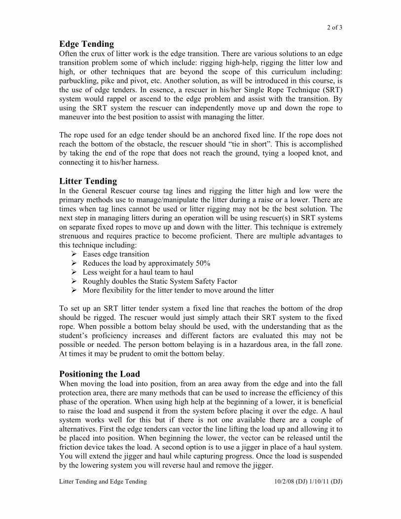
2 of 3
Litter Tending and Edge Tending 10/2/08 (DJ) 1/10/11 (DJ)
Edge Tending Often the crux of litter work is the edge transition. There are various solutions to an edge
transition problem some of which include: rigging high-help, rigging the litter low and
high, or other techniques that are beyond the scope of this curriculum including:
parbuckling, pike and pivot, etc. Another solution, as will be introduced in this course, is
the use of edge tenders. In essence, a rescuer in his/her Single Rope Technique (SRT)
system would rappel or ascend to the edge problem and assist with the transition. By
using the SRT system the rescuer can independently move up and down the rope to
maneuver into the best position to assist with managing the litter.
The rope used for an edge tender should be an anchored fixed line. If the rope does not
reach the bottom of the obstacle, the rescuer should “tie in short”. This is accomplished
by taking the end of the rope that does not reach the ground, tying a looped knot, and
connecting it to his/her harness.
Litter Tending In the General Rescuer course tag lines and rigging the litter high and low were the
primary methods use to manage/manipulate the litter during a raise or a lower. There are
times when tag lines cannot be used or litter rigging may not be the best solution. The
next step in managing litters during an operation will be using rescuer(s) in SRT systems
on separate fixed ropes to move up and down with the litter. This technique is extremely
strenuous and requires practice to become proficient. There are multiple advantages to
this technique including:
! Eases edge transition
! Reduces the load by approximately 50%
! Less weight for a haul team to haul
! Roughly doubles the Static System Safety Factor
! More flexibility for the litter tender to move around the litter
To set up an SRT litter tender system a fixed line that reaches the bottom of the drop
should be rigged. The rescuer would just simply attach their SRT system to the fixed
rope. When possible a bottom belay should be used, with the understanding that as the
student’s proficiency increases and different factors are evaluated this may not be
possible or needed. The person bottom belaying is in a hazardous area, in the fall zone.
At times it may be prudent to omit the bottom belay.
Positioning the Load When moving the load into position, from an area away from the edge and into the fall
protection area, there are many methods that can be used to increase the efficiency of this
phase of the operation. When using high help at the beginning of a lower, it is beneficial
to raise the load and suspend it from the system before placing it over the edge. A haul
system works well for this but if there is not one available there are a couple of
alternatives. First the edge tenders can vector the line lifting the load up and allowing it to
be placed into position. When beginning the lower, the vector can be released until the
friction device takes the load. A second option is to use a jigger in place of a haul system.
You will extend the jigger and haul while capturing progress. Once the load is suspended
by the lowering system you will reverse haul and remove the jigger.

3 of 3
Litter Tending and Edge Tending 10/2/08 (DJ) 1/10/11 (DJ)
Field Exercises
These two techniques should be incorporated into all field evolutions and students rotated
to allow them to serve both functions.
1 of 3
Multi-point Anchors and Pretension Back-ties 9/18/08 (DJ)
Level I Rope Rescue Course
(Skill Acquisition)
Class Title: Multi-Point Anchors/Pretension Back-ties
NFPA 1006/RESET JPR’s: NFPA- 6.1.1
RESET- 1.4
Time: 4 Hours
Scheduling Suggestions: Beginning of the week
Materials/Equipment needed:
Instructor requirements: 5:1 student to instructor ratio
Objectives:
At the end of the lesson the trainee shall be able to:
! Define Multiple-Point Anchor System
! Demonstrate a Load Sharing Anchor
! Identify resultant forces of various angles in anchor systems
! Demonstrate the two techniques of rigging Multiple-Point Anchor Systems
! Describe various reasons for using a Pretension Back-tie
! Demonstrate rigging a Pretension Back-tie

2 of 3
Multi-point Anchors and Pretension Back-ties 9/18/08 (DJ)
Multiple-Point Anchors Systems
The anchor is the foundation of most any rescue system. Of primary importance is the
actual anchor point itself, which can be defined as the object that is providing the means
of supporting the load (i.e. tree, column, hand rail, etc). In the General Rescuer Course
we primarily focused on single point anchors and at times extended those single point
anchors to allow for more efficient rescue operations. During that training, the
importance of good primary anchor selection was emphasized. For Level I the emphasis
is still on the selection of good primary anchor points but the rescuer may wish to share
or distribute the load among several of those anchor points. A system configuration
providing load distribution over more than one anchor point, either proportionally or
disproportionally is called a Multiple-Point Anchor System. The two common techniques
are Load Sharing Anchors (independent legs) and Self Equalizing (“slides” to allow load
distribution). In Level I we will primarily discuss and use Load Sharing Anchors.
There are several reasons why Multiple-Point Anchor Systems would be used. When
rescuers arrive at a technical rescue event often times the patient is located where anchors
may not “line up” with where it would be optimal for the operation. As our technical
abilities increase we should progress from allowing the anchors to dictate where we
conduct operations and make the anchors work for us. By using Multiple-Point Anchor
Systems a Focal Point can be created by extending anchors that are available to a desired
location and connecting them together creating a Load Sharing Anchor.
Another application for Multiple-Point Anchors would be where the individual anchor
points provided are less than adequate for the anticipated force. One way to compensate
for this would be by back-tying the anchor, which will be covered below. Using a
Multiple-Point Anchor System, one could connect several inadequate anchors together
and produce an anchor system capable of sustaining the anticipated force. Incorporating
inadequate primary anchor points is beyond the expectations of a Level I student but
understand that this is a valid technique that may be needed during rescue activities.
As with other areas of technical rescue, when it comes to anchors a solid understanding
of the physics involved can be important. Understanding the affects of angles produced
by our rigging can aid in identifying safety ratios, ensure equipment is not over stressed,
etc. When building Multiple-Point Anchor Systems be sure and identify the angle
produced between the legs coming from the primary anchors. Angles beyond 120 degrees
can produce force multipliers. Forces can quickly exceed the mass of the load. Some
examples of angles and their resultant forces:
120°- 100% or 1T*
150°- 200% or 2T*
160°- 300% or 3T*
165°- 400% or 4T*
170°- 600% or 6T*
*These numbers are approximations. Actual values are different but these
numbers are provided for ease of field use.

3 of 3
Multi-point Anchors and Pretension Back-ties 9/18/08 (DJ)
When rigging Multiple-Point Anchor Systems either avoid angles flatter than 120° or
ensure the rigging is capable of supporting the force that will be applied to it.
There are two techniques we teach in Level I. The first uses a rope tied to an anchor point
using a direct anchor attachment (knot in the end of the rope around the anchor point)
extending it out to the desired location and tying a series of butterfly knots and taking the
running end of the rope back and anchoring that to another anchor point by either a direct
attachment or by running it through a munter hitch to allow flexibility. Variations of this
technique are allowed during field exercises but this is the primary variation taught for
consistency purposes. The second technique uses anchor extensions from multiple
anchors coming to a Focal Point. A rigging plate should be used at the Focal with prusik
hitches connecting it to the anchor extension ropes. The prusiks allow adjustment of the
Focal Point.
Pretension Back-ties
Another technique that can be used to “back-up” or secure a less than adequate anchor is
to use a Pretension Back-tie. As stated above Level I focuses primarily on quality
primary anchor points. Pretension Back-ties takes a potentially inadequate anchor and
produces a quality primary anchor point. This is accomplished by tying a rope, cord,
webbing, etc to the primary anchor point and connecting it to a secondary anchor point
behind it. This most often is done by using a truckers hitch to slightly tension the
rope/webbing between the two anchors.
If one pretension back-tie is used effort should be made to ensure the primary and the
secondary anchors are inline with the direction of loading. Should it not be possible to
line the anchors up, it would be better to use two pretension back-ties creating a “V”. The
loading should fall within the “V” produced by the two back-ties.
In addition to securing a less than adequate anchor this technique can be used to
counteract the effects of leverage (torque). The higher on an object the anchor is tied the
more torque is applied to the anchor point. Rescuers can use pretension back-ties to assist
with supporting the torque produced by anchoring high on anchor points. Often in
addition to counteracting torque, the force vector produced by adding the back-tie can be
transferred directly down the anchor point. For many anchor points such as trees and
metal poles this would put the object in its strongest configuration, compression.
Field Exercises
An overview and demonstration of these techniques should be done to allow the students
to see the skills and ask questions. After this demonstration multiple evolutions should be
conducted using Multiple-Point Anchor Systems and Pretension Back-ties. No other
anchor techniques should be allowed to provide the students time to use the systems in
this lesson. This is also going to be their first time to participate as edge tenders and litter
tenders.
During the evolutions students should be required to practice the skills form previous
lessons (i.e. SRT, Pt Packaging, TTPB, safety factors, etc…).

1 of 3
Transferring Loads & Releasing High Points 7/16/2007 (DJ), 6/7/09 (DJ)
Level I Rope Rescue Course
(Skill Acquisition)
Class Title: Transferring Loads & Load Releasing High Points
NFPA 1006/RESET JPR’s: RESET 1.8, 1.15
Time: 4 Hours
Scheduling Suggestions: After SRT
Materials/Equipment needed: 2- XL Carabiners
4- 20’ Webbings
4- 200’ ropes
1- Jigger
1- Rack
4- Double pulleys
2- Single pulleys
10- Carabiners
1- LRH
2- Prusiks
1- Rescucender
Instructor requirements: 1:5 Instructor to Student ratio
Objectives:
At the end of the lesson the rescuer should be able to:
! Identify the need for load transfers.
! Demonstrate transferring a load from a lower to a raise using a Two Tensioned
Rope System
! Demonstrate transferring a load from a raise to a lower using a Two Tensioned
Rope System
! Demonstrate transferring a load from a lower to a raise using a Single Tensioned
Main Un-tensioned Belay System
! Demonstrate transferring a load from a raise to a lower using a Single Tensioned
Main Un-tensioned Belay System
! Demonstrate the use of a releasing high point

2 of 3
Transferring Loads & Releasing High Points 7/16/2007 (DJ), 6/7/09 (DJ)
Transferring Loads There are times during a raise or a lower that the operation needs to stop and go the other
direction, either back down or back up. This would require the rigging be set up to allow
for this transfer. Otherwise the riggers need to have the technical knowledge to
accomplish this task. The methods below are concepts for accomplishing the task.
Different rigging may necessitate different techniques to transfer loads. At a minimum
the methods below should be covered.
Two Tensioned Rope Systems (TTRS)
Lowering to a Haul
As long as the friction devices have the ability to go both directions (munter, eight plate,
etc…) all that is required is to attach a haul system to the rope and begin the haul.
Haul to a Lower
As long as the friction devices have the ability to go both directions (munter, eight plate,
etc…) all that is required is to remove the haul system and use the friction device to
lower.
Single Tensioned Main Un-tensioned Belay (STM-UTB)
Lower to a Haul (Rack to a 3:1 z-rig with internal prusik PCD)
To transfer the load to a haul, follow these steps:
1. Tie off the rack.
2. Put a pulley and prusik PCD in front of the rack. Use an LRH, or Jigger to extend
these past the rack.
3. Untie the rack and transfer the load onto the prusik and pulley.
4. Unrig the rack and build a z-rig.
Haul to a Lower (z-rig with internal prusik PCD to a rack)
To transfer from a Haul to a lower, follow these steps:
1. With the load on the PCD use an LRH or Jigger and extend another rope grab in
front of the PCD. (If there is an LRH pre-rigged behind the PCD you can skip
step 1 and 2)
2. Transfer the Load from the original PCD onto the new rope grab (this rope grab
will have a releasing ability)
3. Take off the haul cam and pulley attached to the haul cam.
4. Rig the rope into the Rack “behind” the new rope grab device.
5. Use the LRH or jigger to transfer the load onto the rack.

3 of 3
Transferring Loads & Releasing High Points 7/16/2007 (DJ), 6/7/09 (DJ)
Load Releasing High Points Edge Transitions are often the crux of most raising or lowering evolutions. We can raise
someone hundreds of feet but if we can not make the edge transition, we might as well
have left the victim at the bottom of the drop. As has been discussed in much of the text
in this curriculum the use of high help, among other benefits, can greatly increase the
efficiency of edge transitions. To take efficient high help a step further we can include
some sort of load releasing mechanism with our high help. This allows us to release the
load back away from the edge and down to the ground without having to reverse haul. In
essence we create a floating focal point or moving directional that can be moved when
we need it to. There are several ways to accomplish this:
Local Release One method to release a high point can be to use a releasing device at the pulley. Some
options for releasing devices include LRH’s, Jigger, munter hitch, eight plate, etc…. All
of these devices allow us to release the high point under a load. Some down sides to this
method include:
! High help may be to high to reach device
! They lengthen the high point and reduce the amount of height gained by an
anchor
! Require rescuers to be close to the edge
Remote Release Another option is to rig the releasing mechanism away from the high help. Run a rope
through the high help and attach a pulley to one end. Tie the other end off to an anchor
point using a munter hitch to control the load. The rope supporting the load is run through
this pulley. As the load reaches the high point pulley hanging off the end of the remote
releasing rope a rescuer can release the high point pulley using the munter hitch. Some
down sides to using this method include:
! Stretch in the releasing rope can cause the high point pulley to extend too far
! Requires extra equipment
Evolutions Scenarios should be set up to allow students to practice load transfers and releasing
highpoints using the methods above. During those scenarios techniques from previous
lessons should be used: Pt packaging, SRT litter tenders, edge tenders, multi-point
anchors, TTPB, PTBT, safety factors, etc.
1 of 4
Knot Passing 10/08 (Del Castillo) 8/09(Del Castillo)
Level I Rope Rescue Course
(Skill Acquisition)
Class Title: Knot Passing
NFPA 1006/RESET JPR’s: RESET 1.1
Time: 4 Hours
Scheduling Suggestions: After SRT and Transferring Loads
Materials/Equipment needed: 3 200’ Life Safety Ropes 1 Rescuescender
6 Carabiners 3 15’ Webbing
2 XL Carabiners 1 Large Rack
2 Sets Prusiks 1 Jigger
2 Double Pulleys 1 Radium Hitch
2 Single PMP
3 200’ Life Safety Ropes
Instructor Requirements: 1 instructor to 5 students
Objectives At the end of this lesson, the Rescuer should be able to:
! Identify the need for knot passing
! Demonstrate knot passing during a lower using a Two Tensioned Rope System
! Demonstrate knot passing during a raise using a Two Tensioned Rope System
! Demonstrate knot passing during a lower using a Single Tensioned Main and Un-
tensioned Belay System
! Demonstrate knot passing during a raise using a Single Tensioned Main and Un-
tensioned Belay System
! Demonstrate passing a knot through a directional pulley
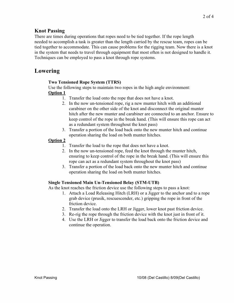
2 of 4
Knot Passing 10/08 (Del Castillo) 8/09(Del Castillo)
Knot Passing There are times during operations that ropes need to be tied together. If the rope length
needed to accomplish a task is greater than the length carried by the rescue team, ropes can be
tied together to accommodate. This can cause problems for the rigging team. Now there is a knot
in the system that needs to travel through equipment that most often is not designed to handle it.
Techniques can be employed to pass a knot through rope systems.
Lowering
Two Tensioned Rope System (TTRS)
Use the following steps to maintain two ropes in the high angle environment:
Option 1
1. Transfer the load onto the rope that does not have a knot.
2. In the now un-tensioned rope, rig a new munter hitch with an additional
carabiner on the other side of the knot and disconnect the original munter
hitch after the new munter and carabiner are connected to an anchor. Ensure to
keep control of the rope in the break hand. (This will ensure this rope can act
as a redundant system throughout the knot pass)
3. Transfer a portion of the load back onto the new munter hitch and continue
operation sharing the load on both munter hitches.
Option 2
1. Transfer the load to the rope that does not have a knot.
2. In the now un-tensioned rope, feed the knot through the munter hitch,
ensuring to keep control of the rope in the break hand. (This will ensure this
rope can act as a redundant system throughout the knot pass)
3. Transfer a portion of the load back onto the new munter hitch and continue
operation sharing the load on both munter hitches.
Single Tensioned Main Un-Tensioned Belay (STM-UTB)
As the knot reaches the friction device use the following steps to pass a knot:
1. Attach a Load Releasing Hitch (LRH) or a Jigger to the anchor and to a rope
grab device (prusik, rescuescender, etc.) gripping the rope in front of the
friction device.
2. Transfer the load onto the LRH or Jigger, lower knot past friction device.
3. Re-rig the rope through the friction device with the knot just in front of it.
4. Use the LRH or Jigger to transfer the load back onto the friction device and
continue the operation.

3 of 4
Knot Passing 10/08 (Del Castillo) 8/09(Del Castillo)
Raising
Two Tension Rope System (TTRS)
Most often a piggy backed haul system is used when rigging TTRS, use the following
steps to pass a knot through a TTRS:
1. As the knot reaches the haul cam of the piggy back system the load can be
held by the progress capture device (PCD).
2. The haul cam can be removed and placed back on the rope beyond the knot.
3. As the knot reaches the PCD, the haul team can hold the load as the PCD is
repositioned onto the other side of the knot.
4. Continue with the raising operation.
STM-UTB
If a piggy back haul system is used follow the same procedure as above (TTRS). If
an inline system (3:1 Z-rig with internal PCD) is being used, use the following steps to
pass knot through the system:
Option 1:
1. As the knot reaches the haul cam, reposition the haul cam on the other side of
the knot.
2. As the knot reaches the PCD attach a Radium LRH to the anchor and extend a
new pulley and PCD beyond the knot. Haul up briefly to transfer the load onto
the new PCD and pulley attached to the LRH.
3. Remove the original pulley and PCD.
4. Continue the haul until the knot reaches the pulley at the haul cam. Remove
the pulley and place it on the other side of the knot and continue the haul.
Option 2:
1. As the knot reaches the haul cam, reposition the haul cam on the other side of
the knot.
2. As the knot reaches the PCD attach a Jigger to the anchor and extend a new
pulley and PCD beyond the knot. Haul up briefly, using the jigger, to transfer
the load onto the new PCD and pulley.
3. Remove the original pulley and PCD.
4. Continue the haul until the knot reaches the pulley at the haul cam. Remove
the pulley and place it on the other side of the knot and continue the haul.

4 of 4
Knot Passing 10/08 (Del Castillo) 8/09(Del Castillo)
Directional Pulleys The easiest way to pass a knot through a pulley is to use a knot passing pulley when rigging,
otherwise follow these steps:
Option 1
1. Pre-rig the directional with a LRH or a Jigger.
2. As the knot gets to the pulley, place another pulley on the opposite side of the knot.
3. Use the LRH or Jigger to release the load onto the new pulley.
4. Remove the original pulley and continue operation.
Option 2
1. As the knot reaches the pulley, put a new pulley attached to a Jigger, on the opposite side
of the knot.
2. Use the Jigger to haul and transfer the load onto the new pulley.
3. Remove the original pulley and continue operation.
Un-tensioned Belays (Raising or Lowering)
Tandem Triple Wrap Prusik Belay (Un-tensioned Belay)
1. As the knot approaches the tandem prussiks, stop the operation and have the mainline
hold the load static.
2. Attach a new Tandem Triple Wraped Prusik Belay to the rope on the opposite side of the
knot.
3. Remove old prusiks and resume belay operation.
Munter Hitch Belay (Un-tensioned Belay) 1. As the knot approaches the munter hitch, stop the operation and have the mainline hold
the load static.
2. Attach a new munter hitch on the opposite side of the knot.
3. Remove the old munter hitch and continue operation.
Evolutions Scenarios should be set up to allow knots to be passed through working systems. During those
scenarios basket-work, SRT litter attendants, edge attendants, and load releasing high points
should be employed.
1 of 2
Field Work 1/11/2010 (WM)
Level I Rope Rescue Course
(Skill Acquisition)
Class Title: Field Work
NFPA 1006 JPR’s: 6.1.3, 6.1.5, 6.1.6, 5.3.1, 5.3.2, 5.3.3
Reset 1.7, 1.16, 1.13, 1.2, 1.3, 1.6, 1.14
Time: 8 hours
Scheduling Suggestions: After Transferring Loads and Releasing High Points
Materials/Equipment needed: Equipment necessary for students to perform all rope rescue evolutions from the week.
Instructor requirements: 1:5 Instructors to Student Ratio
Objectives: At the end of this lesson the rescuer should be able to:
! Perform rescue work while suspended from a rope rescue system
! Perform patient care and movement within a high angle rope rescue system
! Identify the Static System Safety Factor (SSSF) of a rope rescue system

2 of 2
Field Work 1/11/2010 (WM)
Field Work Goals: The Focus of this field work is to give the students more hands on time with advanced rescue systems. A
site should be selected to provide several different types of vertical problems. Scenarios should be
provided, building on the concepts and skills taught during the week. Scenarios should be instructor driven
moving toward student run scenarios. The instructors and students will still be responsible for system
safety.
On Rope Work: Opportunity should be provided for the student to perform task while suspended from a rope. There are
multiple ways to accomplish this and the student needs to perform one of them:
• SRT
• Edge Tending
Patient Care and Movement: During field evolutions the students are expected to perform complete/ongoing patient assessments. The
student should take into consideration the patient’s comfort and safety while being transported. A cache of
medical equipment should be provided. The equipment should be reusable during the class. Instructors will
need to have a list of injuries and vital signs ready prior to the scenarios.
Static System Safety Factor (SSSF) Students should identify the “weakest” component within the system and determine the SSSF. A SSSF of
7:1 or greater will be the goal for all systems. If this SSSF is not reached the reason why should be
identified and either changed to obtain a 7:1 SSSF or a decision (with instructors approval) to use the
system below a 7:1 SSSF must be made.
1 of 3
SRT- Knot Passing (03/09/2009) C. Jenkins
Revised (07/16/2009) C. Jenkins
Revised (Mc) 1/1/11
Level 2 Rope Rescue Course
(Rope Technician)
Class Title: SRT (Single Rope Techniques “Knot Pass”)
NFPA 1006/RESET JPR’s: NFPA- 6.2.1
RESET- 2.1
Time: 4 hours
Scheduling Suggestions: SRT skills will take place the first day of Level 2. The four hour block will take place in
a controlled environment on pre-rigged ropes that allow the student to be lowered if
necessary. For example, rope run through a high point down to a munter hitch.
Materials/Equipment needed:
8 ropes at least 100ft , 8 20ft webbings, 8 XL carabineers, and 8 large carabineers
Instructor requirements: 4 instructors
Objectives: At the end of the training the rescuer should be able to:
! Perform a SRT Knot Pass
! Discuss different types of QAS (Quick Attachment Safeties)
! Pass a non-looped knot while climbing and rappelling
! Demonstrate effective down climb techniques
! Change over from climbing to rappelling
! Change over from rappelling to climbing
! Understand the dangers of Harness Hang Syndrome
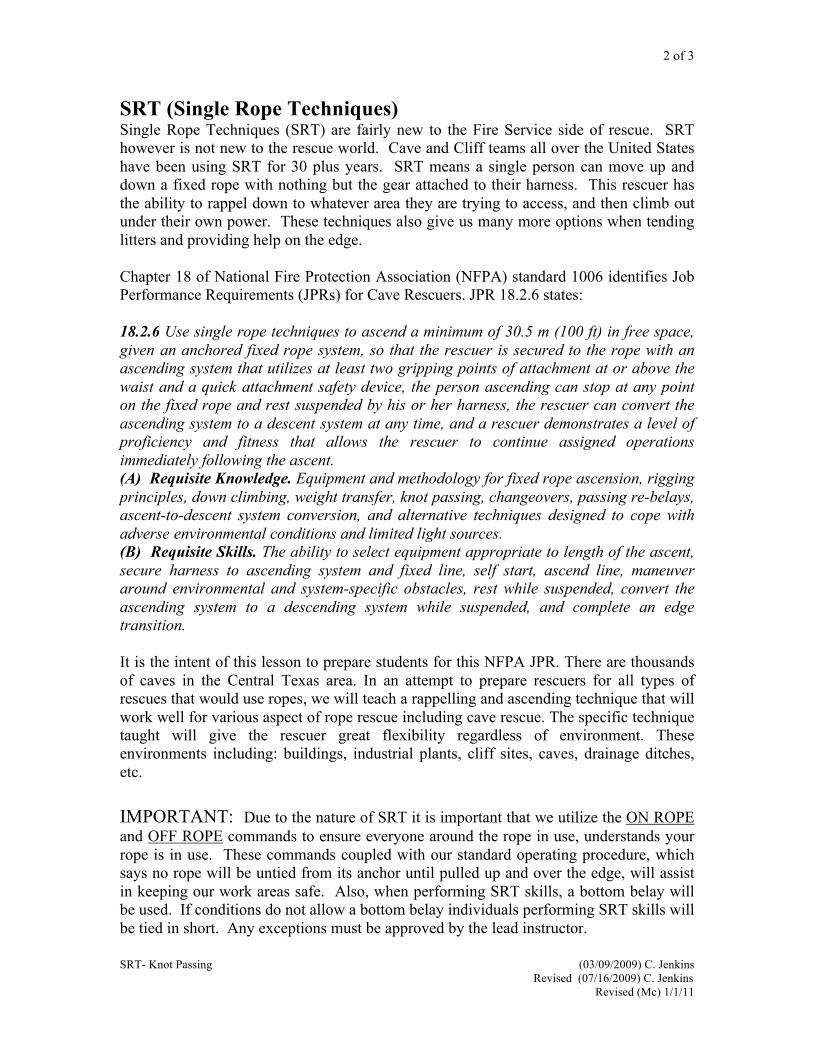
2 of 3
SRT- Knot Passing (03/09/2009) C. Jenkins
Revised (07/16/2009) C. Jenkins
Revised (Mc) 1/1/11
SRT (Single Rope Techniques) Single Rope Techniques (SRT) are fairly new to the Fire Service side of rescue. SRT
however is not new to the rescue world. Cave and Cliff teams all over the United States
have been using SRT for 30 plus years. SRT means a single person can move up and
down a fixed rope with nothing but the gear attached to their harness. This rescuer has
the ability to rappel down to whatever area they are trying to access, and then climb out
under their own power. These techniques also give us many more options when tending
litters and providing help on the edge.
Chapter 18 of National Fire Protection Association (NFPA) standard 1006 identifies Job
Performance Requirements (JPRs) for Cave Rescuers. JPR 18.2.6 states:
18.2.6 Use single rope techniques to ascend a minimum of 30.5 m (100 ft) in free space,
given an anchored fixed rope system, so that the rescuer is secured to the rope with an
ascending system that utilizes at least two gripping points of attachment at or above the
waist and a quick attachment safety device, the person ascending can stop at any point
on the fixed rope and rest suspended by his or her harness, the rescuer can convert the
ascending system to a descent system at any time, and a rescuer demonstrates a level of
proficiency and fitness that allows the rescuer to continue assigned operations
immediately following the ascent.
(A) Requisite Knowledge. Equipment and methodology for fixed rope ascension, rigging
principles, down climbing, weight transfer, knot passing, changeovers, passing re-belays,
ascent-to-descent system conversion, and alternative techniques designed to cope with
adverse environmental conditions and limited light sources.
(B) Requisite Skills. The ability to select equipment appropriate to length of the ascent,
secure harness to ascending system and fixed line, self start, ascend line, maneuver
around environmental and system-specific obstacles, rest while suspended, convert the
ascending system to a descending system while suspended, and complete an edge
transition.
It is the intent of this lesson to prepare students for this NFPA JPR. There are thousands
of caves in the Central Texas area. In an attempt to prepare rescuers for all types of
rescues that would use ropes, we will teach a rappelling and ascending technique that will
work well for various aspect of rope rescue including cave rescue. The specific technique
taught will give the rescuer great flexibility regardless of environment. These
environments including: buildings, industrial plants, cliff sites, caves, drainage ditches,
etc.
IMPORTANT: Due to the nature of SRT it is important that we utilize the ON ROPE
and OFF ROPE commands to ensure everyone around the rope in use, understands your
rope is in use. These commands coupled with our standard operating procedure, which
says no rope will be untied from its anchor until pulled up and over the edge, will assist
in keeping our work areas safe. Also, when performing SRT skills, a bottom belay will
be used. If conditions do not allow a bottom belay individuals performing SRT skills will
be tied in short. Any exceptions must be approved by the lead instructor.

3 of 3
SRT- Knot Passing (03/09/2009) C. Jenkins
Revised (07/16/2009) C. Jenkins
Revised (Mc) 1/1/11
For summaries on the following: descending/rappelling, changing over
from rappel to climb, changing over from climbing to rappel, down
climbing, and self rescue please refer to the Level 1 SRT portion of the
curriculum manual.
SRT Knot Passing Why would there be a knot in the rope you are on? Knots may be tied in the rope you are
on for the following reasons: accidentally placed there or left there due to forgetting to
untie all knots in the rope after use, incorrectly storing the rope after use, deliberately tied
knots to isolate bad spots in the rope or while encountering the connection point between
two separate ropes.
Summary on passing a non-loop knot while climbing ! Climb until the top of your ascender hits the bottom of the knot
! Attach a rope grab device above the knot (e.g. a prussic or basic) and attach a
cows tail to it (you will now have three points of attachment)
! Next, move your handle ascender up above the knot (when the handle ascender is
removed you are still attached by two attachment points)
! You will then step up in your foot loop and move your chest croll up past the knot
! You will then remove your cows tail and rope grab and continue to climb
If the knot is a looped knot (butterfly, bowline, or inline eight) you will not need to use a
rope grab device. Just simply clip a cows tail into the looped knot. Be sure to inspect the
loop and ensure it is life safety. Often people will tie an in line, looped knot to isolate a
“bad” spot in the rope. Then follow the steps listed above, this will allow you to maintain
2 points of attachment at all times.
Summary on passing a non-loop knot while on rappel ! Rappel down until your descender jams into the knot
! Then place your handle ascender above the rack more than 12 inches above the
knot.
! Then step up into your foot loop and attach your chest croll just above your rack
(approximately 6 inches)
! Next you will remove the mini-rack from the rack and re-attach it below the knot,
you will lock it off
! You will then bump your handle ascender down, you may need to down climb
and move the croll closer to the knot
! Next you will step up into the foot loop and remove the chest croll, weighting the
rack
! You will then bump your handle ascender down again just above the knot
! Next you will test your rack, if the rack is rigged correctly, you may remove your
handle ascender and continue your decent.

1 of 3
Team Based Pick-off 4/09 (Lear) 1/11 (DJ)
Level II Rope Rescue Course
(Rope Technician)
Class Title: Team Based Pick-off
NFPA 1006/RESET JPR’s: NFPA- 6.2.2, 6.2.3, 6.2.4
Time:
4 hours
Scheduling Suggestions: Afternoon Day 1
Materials/Equipment needed: Rescue equipment to build required systems:
2 Full SRT harnesses
2 prusik sets
3 XL carabineers
7 L carabineers
4 200’ Ropes
Pickoff Strap or a doubled over prusik loop
2 double pulley’s
4 20’ webbing (or additional prusiks, to be used as anchors)
Jigger
Radium release
Instructor requirements: 4 instructors
Objectives: At the end of this lesson the rescuer should be able to:
! Identify potential pick-off scenarios
! Ability to operate as part of a team to remove a conscious victim suspended in a
high angle environment using a team based pick-off technique
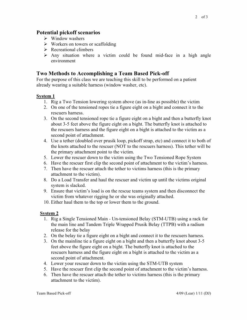
2 of 3
Team Based Pick-off 4/09 (Lear) 1/11 (DJ)
Potential pickoff scenarios ! Window washers
! Workers on towers or scaffolding
! Recreational climbers
! Any situation where a victim could be found mid-face in a high angle
environment
Two Methods to Accomplishing a Team Based Pick-off For the purpose of this class we are teaching this skill to be performed on a patient
already wearing a suitable harness (window washer, etc).
System 1
1. Rig a Two Tension lowering system above (as in-line as possible) the victim
2. On one of the tensioned ropes tie a figure eight on a bight and connect it to the
rescuers harness.
3. On the second tensioned rope tie a figure eight on a bight and then a butterfly knot
about 3-5 feet above the figure eight on a bight. The butterfly knot is attached to
the rescuers harness and the figure eight on a bight is attached to the victim as a
second point of attachment.
4. Use a tether (doubled over prusik loop, pickoff strap, etc) and connect it to both of
the knots attached to the rescuer (NOT to the rescuers harness). This tether will be
the primary attachment point to the victim.
5. Lower the rescuer down to the victim using the Two Tensioned Rope System
6. Have the rescuer first clip the second point of attachment to the victim’s harness.
7. Then have the rescuer attach the tether to victims harness (this is the primary
attachment to the victim).
8. Do a Load Transfer and haul the rescuer and victim up until the victims original
system is slacked.
9. Ensure that victim’s load is on the rescue teams system and then disconnect the
victim from whatever rigging he or she was originally attached.
10. Either haul them to the top or lower them to the ground.
System 2
1. Rig a Single Tensioned Main - Un-tensioned Belay (STM-UTB) using a rack for
the main line and Tandem Triple Wrapped Prusik Belay (TTPB) with a radium
release for the belay
2. On the belay tie a figure eight on a bight and connect it to the rescuers harness.
3. On the mainline tie a figure eight on a bight and then a butterfly knot about 3-5
feet above the figure eight on a bight. The butterfly knot is attached to the
rescuers harness and the figure eight on a bight is attached to the victim as a
second point of attachment.
4. Lower your rescuer down to the victim using the STM-UTB system
5. Have the rescuer first clip the second point of attachment to the victim’s harness.
6. Then have the rescuer attach the tether to victims harness (this is the primary
attachment to the victim).
3 of 3
Team Based Pick-off 4/09 (Lear) 1/11 (DJ)
7. Attach a Jigger to the Mainline. Use the Jigger (extended all the way out) to haul
the Pt up and transfer their weight onto the mainline. The rescuer will also be on
the mainline. If hauling on the Jigger does not allow for a transfer of the Pt’s
weight onto the mainline, the system should be converted to a z-rig to complete
the transfer.
8. Ensure that victim’s load is on the rescue teams system and then disconnect the
victim from whatever rigging he or she was originally attached.
9. Either haul them to the top or lower them to the ground.
Evolutions
Several evolutions should be conducted allowing the students to practice these
techniques. A simulated Victim should be lowered or rappel down and become “stuck”.
Some considerations should be given to having one of the evolutions with a victim
attached at the dorsal (as would be the case in an industrial fall arrest system).
1 of 1
Litter Tending TG & Mc 5/15/09
Level II Rope Rescue Course
(Rope Technician)
Class Title:
Litter Tending
NFPA 1006/RESET JPR’s: NFPA- 6.2.1, 6.2.2, 6.2.3
Time: 4 Hours
Materials/Equipment needed: Classroom:
Audio/Visual equipment for PowerPoint
Dry Erase/markers
Instructor requirements: 4 instructors for 12-15 students
Objectives: At the end of the training the rescuer should be able to:
! Define what an attendant is
! Know the benefits and limitations of litter attending
! Be a litter attendant for a vertical or horizontal configured stokes/ferno/sked

2 of 2
Litter Tending TG & Mc 5/15/09
Litter Attendant (definition)
-A person who rides up with (or down with), climbs up with, or rappels with a
litter. When the litter includes a patient this is often a medically-trained person.
(On Rope. 1996)
Pros & Cons of Litter Attending
Pros:
1. Medical Considerations, specifically managing the patient’s airway and
controlling major bleeding
2. To attend to apprehensive or anxious patients
3. Tag lines are not practical due to environmental or industrial constraints
Cons:
1. Manpower restraints
2. Two person load on system (ensure you meet 7:1 SSSF)
3. May require specialized equipment and training
4. May complicate edge problem
Medical Considerations:
As a litter attendant there may be minimal medical intervention while on rope and
tending the litter. For example: controlling major bleeding and/or opening an airway may
be all a litter attendant is able to do while on rope an attending to the litter.
Technique #1 Horizontal litter configuration/Single Rope
Techniques and tying in short

3 of 3
Litter Tending TG & Mc 5/15/09
Technique #1 Vertical litter configuration/Single Rope Techniques and
tying in short
With the litter in a vertical configuration, have a tail coming off the main line at the litter
bridle focal (long tail bowline and butterfly knot are still appropriate knots to use here). It
should be approximately 8 to10 feet, long enough to allow the attendant to maneuver
above, below and around the litter. Tie a figure 8 on a bight at the end of the main line tail
and tie-n-short to the attendant at their waist frontal attachment point. When the litter is in
a vertical presentation the attendant should initially position themselves to where their feet
are just below the litter. Also, deviating part of the mainline away from the patients face is
a good technique. A carabineer clipped in a top handle with the rope running through it
can accomplish this. Remember the attendant has two options when tending the patient in
Technique #1 Horizontal litter configuration/Single
Rope Techniques and tying in short For technique one, the attendant will use their personal rope
ascending system (e.g. frog) and attach to tail coming off main
line located at litter bridle focal. The tail coming off main line
can either be a tail from a long tail bowline or butterfly knot.
Allow 8 to 10 feet of tail off of main line. Furthermore the
rescuer should tie a figure on a bight at the end of the tail of the
main line and tie-n-short to the attendant at their waist frontal
attachment point. When the attendant is positioning himself
initially, he should try to align the top of the croll on the
attendant’s harness with the top rail or top edge of the litter.
Adjustment can be made as litter attendant is managing the litter
to its destination. The attendant should initially try to position
themselves to where they can establish a good rappel position,
with their legs, under the litter while also providing protection for
the patient [Note a tri-link at the bridle focal may be an optimal
attachment point for this configuration].
One option for the litter attendant is bring their legs up through
the bridles above the patient . In this instance, the rescuer can
push away from obstacle while still comforting the patient.
Furthermore, a nice technique is to load the system first with the
litter over the edge. Then ease the attendant into position, if the
conditions allow, using a 30’ piece of webbing looped around
attendant’s front attachment point with ends wrapped around a
friction point. The webbing will assist in lowering him into
position. Once in position remove webbing from the attendant.
Remember to adjust the litter bridles for a head-up orientation is
unless patient medical dictate otherwise.
Note: Tying in short will create a loop below the rescuer, monitor
loop to ensure it does not create a hindrance.
Bridle Tail end of
main

4 of 4
Litter Tending TG & Mc 5/15/09
a vertical system. Option one he can remain next to the patient possibly assisting in
negotiating obstacles. Option two, he could straddle the patient, keeping the patient at least
arms length away, and maintaining a good rappel position, to facilitate good safety and
control. Finally a good technique if possible is to load the system with the litter first and
then the attendant should position themselves.
Technique #2 Horizontal litter configuration/Attendant using a jigger
system
The second technique requires attaching a jigger system to the focal point of the bridle with
the progress capture, on the jigger, near the attendant. There may be other options which
will be covered more in depth below. Furthermore, you should create a tail coming off
main line (tying either a long tail bowline or butterfly knot). At the end of the tail of the
main line, tie a figure 8 on a bight and attach it to the frontal attachment point of the
attendant. The attendant should be diligent in keeping the jigger away from the patient’s
body. Also, the attendant should be mindful, that the tails from the main line and from the
jigger will not get hung up in the surrounding environment. The attendant should initially
position their legs into a good rappel position under the litter (possibly placing the top of
the croll of the attendant’s harness at the rail of the litter). For loading the system see above
for suggested sequence.
PCD
Orientation of Jigger
Jigger orientation options (continued
from above):
1. Move the PCD (progress capture
device) and position it closest to the
attendant’s harness attachment point.
2. Leave the PCD in place (attached
at the tender) and run the haul end of
the rope trough the carabineer
attached to the focal point. This is
essentially a redirect through a
carabineer allowing for the tender to
pull down instead of up.

5 of 5
Litter Tending TG & Mc 5/15/09
Technique #2 Vertical litter configuration/Attendant using a jigger
system
Same considerations as listed above should be given. Only difference is the patient is in a
vertical orientation. When the attendant is initially positioning himself. Try to have their
feet fall just below the litter.
1 of 3
Artificial Anchors (07/01/2008) C. Jenkins
Revised (07/16/2009) C. Jenkins
Level II Rope Rescue Course
(Rope Technician)
Class Title: Artificial Anchors
NFPA 1006/RESET JPR’s: RESET- 2.8
Time: 4 hours
Scheduling Suggestions: Afternoon day two
Materials/Equipment needed:
Equipment to build mono-,bi-, & tri- pod. Equipment to do haul and lower evolutions
Instructor requirements: 4 instructors for 12-15 students
Objectives: At the end of the lesson the rescuer should be able to:
! Define artificial anchor
! Build a picket anchor
! Understand the difference between a mon-pod, bi-pod, and tri-pod
! Use wrap and frap lashing
! Understand and explain resultant forces vectors
! Safely rig and use a Bi-pod in a high angle environment
! Demonstrate use of a picket system

1 of 3
Artificial Anchors (07/01/2008) C. Jenkins
Revised (07/16/2009) C. Jenkins
Artificial Anchor An artificial anchor point is constructed by us the rescuers. We may need to apply this
technique in situations were no other high help is available or the existing high point is not
sufficient for the load being applied to the system. Most of the time it is beneficial to the rescue
if a high point is used. Essentially the rescuer will select a point in mid air and construct an
artificial anchor at the point he or she selected. When building these artificial anchors we must
be very careful in our rigging to ensure a safe system. Resultant force vectors will play a major
role in how we rig.
Picket Anchor A picket system is a type of portable anchor that can be assemble by rescuers when no other
anchors are available. These anchors can be bombproof if rigged correctly. The key is
placement. This anchor should be built so that the force applied is directly inline with the picket
anchor. Construction is as follows:
! The pickets should be at minimum 4-5ft long, so that 3ft may be driven into the ground
leaving 1-2ft above ground
! Drive the pickets into the ground at a 15 degree angle in the opposite direction or the
force being applied
! Space the pickets 3ft apart
! Use webbing to lash the pickets together.
! Tie a loop of webbing, place the loop over the first two pickets. The webbing should be
at the top of the first picket and the bottom of the second picket.
! You will then use a windlass to twist the webbing in the center of the two pickets. Twist
until tight. Drive the windlass into the ground or tie it to a picket to secure it
! Repeat for the next pickets
! Secure the rope being anchored to the bottom of the first picket.
Caution: Pickets are not suitable for all soil types, and more than 3 pickets
may be necessary to build an efficient anchor. Remember the way you rig
will dictate the success of the system

1 of 3
Artificial Anchors (07/01/2008) C. Jenkins
Revised (07/16/2009) C. Jenkins
Mono-pod (Gin Pole) A gin pole or monopod should have a minimum of 3 guy lines, but 4 is preferred, spaced at 120
degree angles. If anchor availability permits. The ground end of the pole should be secured,
either anchored to the surface with a picket or placed in some type of natural opening or hole.
The gin pole should be tilted so that the resultant force vector will travel directly down the pole.
This causes the forces on the pole to be in compression rather than shear. The forces being in
compression is the key to creating an efficient monopod.
A 14ft roof ladder found on many fire trucks makes a very efficient Mono-pod. When tying the
guy lines and other attachments they should be rigged and tied to the beams of the ladder and
not the rungs. This will be demonstrated in the field.
Bi-pod (A-Frame) A bi-pod or A-frame is made up of two support legs. The top of the 4x4’s need to be lashed
using the wrap and frap method. This allows the support members to be attached to each other
and provides an attachment point for the rigging. The rescuer will then proceed as follows:
! Spread the legs apart to create the a-frame
! Attach 2 ropes to the top of the a-frame so we do not drop the a-frame off the edge
! Position the a-frame at the ledge
! Stand the a-frame up using the 2 attached ropes for control
! The two ropes will now become your guy lines or back ties
! Secure the guy lines with some type of friction devices at chosen anchors
! A front guy line is recommended but not always applicable
You will maximize the strength of the a-frame by tilting it to the edge. Tilt until the axel of the
pulley supporting the working line bisects the angle between the legs of the a-frame. This will
position the resultant force vector in the optimal place. Which will evenly disperse the load
onto the a-frame. Once the a-frame is placed the feet of the a-frame must be secured either by
lashing them together or securing them to the ground with pickets, which is preferred.
Tri-pod A tri-pod is made up of 3 support legs. The top of the 4x4’s need to be lashed using the wrap
and frap method. This allows the support members to be attached to each other and provides an
attachment point for the rigging. The rescuer will then stand the tri-pod up. Once positioned
over the hole or at the edge. The feet of the tripod need to be secured together. When the tri-
pod is loaded the resultant force vector must stay inside the 3 support legs as close to center as
possible. If the resultant force vector is outside the legs of the tri-pod, it will fall over unless
additional rigging is used. Back ties will need to be used to counter act the resultant force
vector.
1 of 3
Artificial Anchors (07/01/2008) C. Jenkins
Revised (07/16/2009) C. Jenkins
Wrap and Frap Wrap and Frap, is the method in which the top of the 4x4’s are lashed together when building
bi-pods, tri-pods, etc. You will start by lining the up the 4x4’s side by side and several inches
apart. Next you will use a 30 ft piece of webbing to tie a clove hitch around the top of one 4x4.
Then you will wrap the webbing around the other 4x4(s). You should wrap a minimum of 5
times. Next the rescuer will begin to Frap between the 4x4s, around the webbing wraps you just
created. Fraps are created by wrapping parallel to the 4x4’s around the wraps. You should frap
a minimum of 3 times. When frapping, fraps should be snug but not tight. When the anchor is
stood up the webbing will be under tremendous stress if frapped to tight.
Resultant Force Vector The resultant force vector is an unseen but very real force we create when rigging. When we
pull a rope inline end to end all the force applied travels inline with the rope. When the rope is
deviated resultant forces are created. The resultant force will bisect the angle created by the
deviation in the rope. This is important when building artificial high points, because a resultant
force outside of the support legs will cause instability in the a-frame or tri-pod.

1 of 8
Highlines and Guidinglines 4/9/09 (DJ) 1/10/11 (DJ)
Level II Rope Rescue Course
(Rope Technician)
Class Title: Highlines and Guidinglines
NFPA 1006/RESET JPR’s: NFPA- 6.2.5, 6.2.6
RESET- 2.6, 2.7
Time: 8 Hours
Scheduling Suggestions:
Materials/Equipment needed:
Instructor requirements: 5:1 student to instructor ratio
Objectives:
At the end of the lesson the trainee shall be able to:
! Describe why Highlines are relevant to technical rescue training
! Define Highline
! Define Guiding line
! Identify the type of highline taught to RESET Rope Level Two students
! Describe and use the term Mainline and Control line as it pertains to a Drooping
Highline
! Identify the field application of angles and their resultant forces
! Describe the purpose of a Guidingline
! Describe 6 considerations for Highlines and Guidinglines

2 of 8
Highlines and Guidinglines 4/9/09 (DJ) 1/10/11 (DJ)
Introduction
Highline and Guidinglines are often viewed as a culmination of rope rescue skills. These
systems use all of the skills and techniques taught in the RESET curriculum and give
another application for their use. The rigging practice and opportunity to examine the
physics involved in these systems is one of the more beneficial aspects of building
Highlines and Guidinglines. This gives rescuers the chance to fine tune their
understanding of these concepts and help drive them home. Many times the validity of
their teaching is debated. Questions like: “Are we really ever going to use one of these
for real?” and “Why should I learn these skills if we will probably never use them?” The
answer is muli-layered. “Are we ever going to use one of these for real?” Maybe;
possibly; it is another technique for a rescue technician to be able to pull out of their hat
when faced with complex rescues. “Why should I learn these skills if we will probably
never use them?” For one it is a Job Performance Requirement in NFPA 1006. In
addition to that, as it is stated before the rigging practice and deeper understanding of
physics are probably the real value in these techniques. Once a rescuer has the ability to
orchestrate and truly understand what is going on with a highline he or she will be able to
more clearly and efficiently build all systems and execute their use.
Many people make unfounded comments about Highlines and Guidinglines. Many of
these comments claim they are “unsafe” or “dangerous”. People whom have a narrow or
limited understanding of these systems generally make these statements. In contrast there
can be extreme exposure with these systems. Exposure as defined in climbing and rescue
alludes to being exposed to a lofty or seemingly long fall, or the consequences of failure
are more pronounced than normal. This is not to be confused with more dangerous. When
working at height, we are always “exposed” to falls. But when we are working next to a
cliff or building the “exposure” is not as great as when someone is suspended midway on
a highline several hundred feet up. Both are vulnerable to the same hazard but the
“exposure” is greater with one than the other. Simply put if these systems are built
correctly they are no more dangerous that the other systems we stake our lives on.
Highlines
Highline is defined as a horizontal rescue system used to transport equipment or people
across a span. These systems are often called Tyrolean’s. A Carriage made up of pulleys
is placed on a horizontally tensioned Mainline (Trackline) and is operated horizontally by
Control Lines (Taglines). Generally, with a Highline the majority of the weight is
supported by the Mainline. The Control Lines just allow us to ferry the load back and
forth on the Mainline.
This technique can be used to cross rivers and gorges. It can be used to span between two
buildings. These systems may also be used over confined spaces, caves, trenches, etc to
allow the load to be raised up vertically with high help and then transported horizontally
to a landing area. In Swiftwater rescue they are used to operate boats and pick people off
of objects in a flow of water.
Highlines may be purely horizontal or at a sloped angle. With few exceptions the rigging
for sloped and horizontal Highlines are the same.

3 of 8
Highlines and Guidinglines 4/9/09 (DJ) 1/10/11 (DJ)
Guidinglines
Guidingline are similar to extremely sloped Highlines in that they have a carriage that is
placed on a tensioned rope (the Guidingline). Except with a Guidingline the weight is
supported primarily by a two-rope system (either a TTRS or STM-UTB). Essentially
Guidinglines are just a supplement to a normal vertical two-rope system. The Guidingline
allows us to pull the load away from obstacles. Examples of this would be:
• Talus pile below a cliff
• Tower with a waist
• Obstacles below the vertical plain (cars, construction equipment, etc)
• Tiered building
The general principle is the two-roped system would be doing the lowering and/or raising
and the Guidingline would just be deviating the load away from obstacles.
Highlines
There are as many variations of Highlines as there are Haul Systems (endless). In the
RESET Rope Rescue Level II course we will only be teaching the Drooping Highline
(sometimes referred to as a Kootenay Highline). The principles of Drooping Highlines
can be applied to multiple variations of Highlines.
There are two ends or sides to a Highline. In an effort to stick to NIMS terminology we
will use the designation Division to separate the different ends. The end, which is
normally characterized by having the majority of activities and resources including:
equipment staging, additional personnel, command components, and various other
items/functions will be called Division A. Some schools and agencies call this the “near
side” or “working end”. Division A often appears to have the majority of the “work”
occurring. In reality there is a lot of activity on the other side as well. The other end will
be called Division B. Some schools and agencies call this the “Dumb-end” or “Far-side”
because it is on the far side away from the bulk of activities. These terms will aid us in
clearly communicating between the two sides when coordinating a highline operation.
The first major complication will come when trying to get the ropes, rigging gear, and
rescuers across the span. There are various solutions to this problem, including:
! Line gun
! Big Shot
! Rock and string
! Bow and arrow
! Rescuers crossing the span to the other side
! Boat
! Helo
When sending the first rope(s) across try and send two. This will aid in facilitating the
rigging much better.

4 of 8
Highlines and Guidinglines 4/9/09 (DJ) 1/10/11 (DJ)
The Mainline
The terminal end of the Mainline rope should be anchored to a suitable anchor on the
Division B side. This can be any anchor we use in our other technical systems. Though
the most common anchoring method used is the tensionless hitch. This is common for
two reasons:
1. After a prolonged period of time a knot under constant tension from the Mainline
system will be extremely difficult to untie.
2. This method will allow us to retain the majority of the ropes strength. It should be
noted that the Division A would normally incorporate a method of attachment that
will be below the ropes MBS (Tied off Munter, Tandem Prusiks, Knot, etc). So,
efforts to maintain 100% of the ropes strength are negated if the same is not true
on the other end.
On the Division A, one of the Mainline systems used in General Rescuer or Rope Level I
should be used:
! Munter Progress Capture Device (PCD) with a piggybacked Block and Tackle
haul system
! Inline Z-Rig with TANDEM Prusik PCD, with a rack and conversion equipment
to transition to a lower.
o Note: Tandem Prusiks are required for capturing progress in a Highline
Mainline because of its dynamic characteristics. The Mainline will see
dynamic loading from the load “bouncing”.
The way the load is adjusted in elevation is by tensioning (by a raising system) or un-
tensioning (by a lowering system) of the Mainline. Generally the load should only be
raised enough to clear whatever obstacle we are trying to work over.
The pre-tensioning of the Mainline should only done by one person. Once the load is on
the Mainline the Rule of 18 (for !”, 12.5mm rope) or the Rule of 12 (for 7/16”, 11mm
rope) may be applied. Remember, as stated above only raise the load enough to clear the
obstacle. If the tensioning rules will not allow you to clear the obstacle, a Highline is
probably not your solution to the problem.
Rule of 12 and Rule of 18
The Rule of 12/18 is calculated by taking the number of haul team members and
multiplying that by the mechanical advantage of the haul system. (Ex. 4:1 with 3 people
= 12 or 5:1 with 2 people = 10 or 3:1 with 6 people = 18)
The principle behind the Rule of 12/18 is to ensure we do not overstress the components
of our systems. This is based on each person being able to input 50 pounds of force (lbf)
into a system (this is based on a study of hand strength). It is also based on an attempt to
stay within the confines of a 10:1 static system safety factor/ratio (SSSF) (remember in
RESET the minimum SSSF is 7:1). If we retain 100% of a 7/16” (11mm) rope the MBS
should be around 6000lbf (27kN). With 7/16” rope we use the Rule of 12. So if the factor
is multiplied by 50lbf, this gives us 600lbf (12X50=600). 600 lbf of input compared to
the 6000lbf MBS gives us a 10:1 SSSF. This is the same with the Rule of 18 for !”
(12.5mm) rope with a 9000 lbf (40kN) MBS (18X50=900). 900lbf compared to the
9000lbf MBS gives us the same 10:1 SSSF. These numbers and explanation provides the
history of where the Rule of 12/18 comes from and the conditions in which it was
intended.

5 of 8
Highlines and Guidinglines 4/9/09 (DJ) 1/10/11 (DJ)
Our defined conditions and style of rigging is different from the description above. For
RESET we attempt to maintain a 7:1 SSSF and we commonly use knots or other strength
reducing methods that will not allow us to maintain 100% rope strength. So if we look at
the numbers from our perspective; !” (12.5mm) rope with a knot tied in it gives us
roughly a 6000 lbf breaking strength. If we applied the rule of 18 exerting 900 lbf onto
the system this gives us a 6.6:1 SSSF. A 7/16” (11mm) rope with a knot tied in it gives us
a 4200 lbf breaking strength. If we applied the rule of 12 exerting 600 lbf onto the
system this gives us a 7:1 SSSF. Both ideologies provide us with the same outcome,
which is an attempt to control the forces exerted within a system while staying within our
targeted SSSF.
It should be understood that there are many of these highline tensioning “rules” in the
rope rescue world. Most give methods to prevent “over-tensioning”. So when applying
the Rule of 12/18 or other methods be sure and identify them as defining the upper limits
of tension and not the desired tension.
Angles and Forces
The Rule of 12 and 18 are a good rule of thumb. But as you can imagine, not everyone
inputs only 50lbf into a system. Another tool, sometimes preferred, that can be used to
determine the loading of a Highline is identifying the “interior” angle of the Highline at
the Carriage. With practice this can be estimated extremely accurately. Once the interior
angle is determined we can determine the approximate resultant force being exerted on
each leg of the Mainline. These angles were discussed in Rope Level I. Some examples
of angles and their resultant forces are:
120°- 100% or 1T*
150°- 200% or 2T*
160°- 300% or 3T*
165°- 400% or 4T*
170°- 600% or 6T*
*These numbers are approximations. Actual values are different but these
numbers are provided for ease of field use.
With these factors and the estimated weight of the load the rescuer can estimate the
resultant force on the Mainline “legs”. These numbers are proven through mathematics
(Trigonometry) and are calculated with the load at mid-span and the system in
equilibrium. When the load is pulled to one side or the other, by the Control lines, these
numbers are no longer accurate. But the forces are close enough for fieldwork that
further. Furthermore, the forces exerted on both sides of the carriage are not equal. Once
the system is out of equilibrium the longer leg will see less force and the shorter leg will
see more force. This is why the load tries to move back to center, because the forces are
unequal and it is trying to put it back into equilibrium. Additionally the Control line is
supporting a portion of the vertical force. The amount of force supported by the control
line will be dependant on the angle of the “slope” between the load and the side the load
is being raised/ferried to. Again the force differences between the actual force values and
the estimated values are close enough for fieldwork.
6 of 8
Highlines and Guidinglines 4/9/09 (DJ) 1/10/11 (DJ)
Control Lines
With the Mainline rigged and the carriage in place we need Control Lines to move the
load from one side to the other. Many people rig these Control Lines to act as “Belays”
in addition to traversing the load. Their belief is that if the Mainline were to experience a
failure the Control Lines would be able to catch the load before it hit the surface below.
RESET does NOT consider them to be Belays. In order for the Control Lines to
accomplish this task it requires a considerable distance below the load for them to arrest
the load. As stated above our goal is to only raise the load enough to clear the obstacles.
Additionally the terrain in the central Texas area does not usually offer us the distance
required to allow the load to travel before the Control Lines would arrest the load. In the
RESET program we rig all systems for success. If there is any concern the Mainline will
fail or not operate correctly it should not be used in the first place.
On both sides, Division A and Division B, systems are rigged to traverse the load back
and forth. Any system taught in General Rescuer or Rope Level I can be used for the
Control Lines:
! Munter Progress Capture Device (PCD) with a piggybacked Block and Tackle
haul system
! Inline Z-Rig with single prusik PCD, with a rack and conversion equipment to
transition to a lower.
o Note: Tandem prusiks are not required. They are not expected to be
dynamically loaded.
The ends of these ropes should be attached directly to the carriage with a knot and a
carabiner. If a litter tender is going to be attached to the system, on one control line, a
butterfly knot should be used to attach the end of the rope to the carriage allowing a tail
to be attached to the tender as a second point of attachment.
Litter Tender Attachment
If a litter tender is going to be attached to the system he/she should use the Jigger method
of attachment to the system. This will allow him/her to move up and down and position
themselves in the most advantageous position. Additionally as described above a tail
should come from one of the control lines providing a second point of attachment.
A second method for producing the second point of attachment, should using the end of
the rope not be practical, uses a loop of webbing or cordage. Simply tie the webbing or
cordage into a tether from the carriage to the tender. Just ensure it is used in such a way
that maintains appropriate Static System Safety Factors.
With a litter and litter tender attached to the carriage there may be a need for the
combination to spin or twist. This spin or twist may be difficult or impractical due to the
direct attachment to the carriage limiting the ability for this to occur. A solution to this
could be to use a swivel between the litter and the carriage. This will allow it to spin and
“swivel” as needed to negotiate obstacles. Care should be taken to minimize the twisting
of ropes that are connected both above and below the swivel.
7 of 8
Highlines and Guidinglines 4/9/09 (DJ) 1/10/11 (DJ)
Operation
The intent of the Drooping Highline is to be simple. It is rigged with systems that have
been used over and over again in previous courses and evolutions. We are now just
applying them horizontally instead of vertically.
To move the load vertically (up and down), use the system on the Division A side to
tension and un-tension the Mainline. To traverse the load horizontally use the systems
rigged on both Control Lines. One system will need to be in the “Lowering” mode and
one in the “Raising” mode. Coordination should be used to try and minimize the amount
of “fighting” between these two systems.
Festoons
When rigging horizontal rope systems over a long distances the droop created in the
control lines can be considerable. The droop can be so large that it actually impedes on
efficiency. One method to assist with managing this droop is using festoons. By taking
accessory cord of any size (does not need to be life safety) and girth hitching it to the
control line and using a carabineer to connect it to the Mainline. This should be done
about every 20 feet or so depending on the amount of sag created. The downside to
festoons is they can get in the way when reversing the direction of travel. Now each one
must be removed as it comes back to the side in which they were originally attached.
Guidinglines
As stated above Guidinglines are just a supplement to a normal two-rope vertical system.
A TTRS or STM-UTB should be constructed to do the raising and lowering as with any
other operation. The carabiners connecting to the load should be connected directly to the
load. A pulley should connect the load to the Guidingline. Several variations of attaching
the load to the guiding line are possible. Most often rigging it as a single focal point
horizontal litter works well.
The first step with a Guidingline is identifying where it needs to be rigged. Then as with a
Highline the rope must be taken on the other side of the obstacle. One end should be
anchored to a life safety anchor and the other end will go to the same type of systems
used in the General Rescuer and Rope Level I (Munter /Block and Tackle or z-rig with
single prusik PCD/Rack). The decision as to which side the tensioning system will be is
on will be dependant on site needs.
Operation
The two-rope system should be operated as usual. The difference will be that when the
load is suspended by the two-rope system the Guidingline can be tensioned or un-
tensioned to deviate the load away from the obstacle.

8 of 8
Highlines and Guidinglines 4/9/09 (DJ) 1/10/11 (DJ)
Considerations for Highlines and Guidinglines ! When rigging on the edge of a span get as much height as possible. When you
think you are high enough go higher.
o Natural high help
o Possibly rig on the floor above
o Use bi-pods or tri-pods
! Be sure and have a good clear and sizable “Landing Zone” (LZ) for the basket on
the side the load is being traversed to.
! Be prepared to pass knots including: through the Mainline and Control Line
systems, deviations/redirects, and for the Carriage on the Mainline.
o Think about the use of knot passing pulleys
! If time is available “test” the system prior to its use to ensure it will work as
planned.
! Keep angles at a minimum.
! If the Mainline cannot be tensioned enough to clear obstacles, Highlines are
probably not your solution. Consider alternative rescue plans.
Evolutions Time should be offered to allow students to see these systems demonstrated by building
“Mini-Highlines” between trees. Discussions about all the characteristics of these
systems should be undertaken prior to moving past the Mini-Highline session. Full-scale
versions of both a drooping Highline and a Guidingline should be built and operated.

1 of 2
Field Work 3/16/2009 (WM)
Level II Rope Rescue Course
(Rope Technician)
Class Title: Field Work
NFPA 1006 JPR’s: 6.2.1, 6.2.2, 6.2.4, RESET 2.8
Time: 8 hours
Scheduling Suggestions: After High Lines
Materials/Equipment needed: Equipment necessary for students to perform all rope rescue evolutions from the week.
Instructor requirements: 1:5 Instructors to Student Ratio
Objectives: At the end of this lesson the rescuer should be able to:
! Perform rescue work while suspended from a rope rescue system
! Perform patient care and movement within a high angle rope rescue system
! Demonstrate the operation of a team based pickoff
! Identify the Static System Safety Factor (SSSF) of a rope rescue system
2 of 2
Field Work 3/16/2009 (WM)
Field Work Goals: The Focus of this field work is to give the students more hands on time with advanced rescue systems. A
site should be selected to provide several different types of vertical problems. The morning scenarios
should be more instructor driven with the students being allowed more control as the day progresses.
A full day of field work should be provided, building on the concepts and skills taught during the week.
Scenarios should be instructor driven in the morning and then, depending on the class, student driven in the
afternoon. The instructors and students will still be responsible for system safety.
Artificial anchors: There are times that suitable anchors are not available or are not in the most advantageous location. When
this occurs the ability to build your own anchors may be the solution. Building anchors takes time however
and this should be considered before using artificial anchors.
On Rope Work: Opportunity should be provided for the student to perform task while suspended from a rope. There are
multiple ways to accomplish this and the student needs to perform one of them:
• SRT
• Litter tender attached to the litter
• Edge Tending
• Team based pickoff
Patient Care and Movement: During field evolutions the students are expected to perform complete/ongoing patient assessments. The
student should take into consideration the patient’s comfort and safety while being transported. A cache of
medical equipment should be provided. The equipment should be reusable during the class. Instructors will
need to have a list of injuries and vital signs ready prior to the scenarios.
Static System Safety Factor (SSSF) Students should identify the “weakest” component within the system and determine the SSSF. A SSSF of
7:1 or greater will be the goal for all systems. If this SSSF is not reached the reason why should be
identified and either changed to obtain a 7:1 SSSF or a decision (with instructors approval) to use the
system below a 7:1 SSSF must be made.

!
!
"##$%&'(!!
!
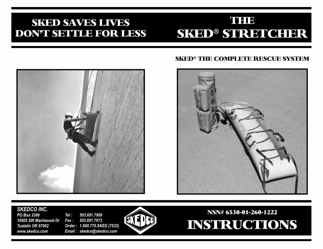
!"#$%#&'($!)#!*"#)
+$+,(-./010213-012333
4+$!)5*!46+$
$%#&($78#$(948#$&6+:!($#!!9#(;6)(9#$$
!"#$%&'()%*+&',-.'//0121313'!4'5678699:;'$<=>6?6;@7'&A'0B1CDEEE*9F:GH-*H-I
=:?'J'' 31/*C02*B010K6.'J'' 31/*C02*B0B/&<G:<'J''2*L11*BB1*!"#$'MB3//N#I6@?'J'' 9F:GH-O9F:GH-*H-I
$%#&'(!"#(*6<=9#!#()#$*5#($>$!#<

!"#$%&'()&'*"#+,"#,-"(%,.(%/0&+1,"2,'01,34156,71+/(1,3-+'189,:"(,;*)),!,#5,*',&,<&)(&=)1,'""),'0&',;*)),1#&=)1,%1+/(1+,'",=1,.1%2"%815,+&21%>,2&+'1%>,,1&+*1%9,?01,34156,3'%1'/01%,*+,&#,1#'*%1)-,5*221%1#',/"#/1.', *#, +'%1'/01%, 51+*$#9, ?01%12"%1>, ."'1#'*&), %1+/(1%+, +0"()5,.%&/'*/1,,2&8*)*&%*@1,'018+1)<1+,;*'0,'01,34156,.%*"%,'",(+*#$,*',"#,&#,&/'(&),%1+/(19
?01,34156,3'%1'/01%,.%"<*51+,1A/1))1#',.&'*1#',+(.."%',,.%"'1/'*"#9,B";1<1%>,*',*+,CD?,51+*$#15,&+,&,+.*#&),*88"=*)*@&'*"#,51<*/19,E2,&,+.*#&),*#F(%-,*+,+(+.1/'15>,+1/(%1,'01,.&'*1#','",&#,&..%"<15,+.*#&),*88"=*)*@&'*"#,51<*/1,.%*"%, '",.)&/*#$,0*8G01%, *#, '01,341569,?01,34156,3'%1'/01%,;*)),&//"88"5&'1,)"#$,,+0"%',=&/4="&%5+>,+/"".,+'%1'/01%+>,D%1$"#,3.*#1,3.)*#',EEH,,8"+',"'01%,*88"=*)*@&'*"#,1I(*.81#'9,J,=&/4="&%5,8(+',=1,(+15,*#,/"#F(#/'*"#,;*'0,'01,34156,3'%1'/01%, "#, .&'*1#'+,;0", 0&<1, +(+'&*#15, *#F(%*1+, '", '01, +0"()51%,&%1&9
!"#"$%&'&("!)%*+"%&,")-%&*$"*.+"$%/0%1%&2!34"%3$566"*7,K+1,'01,+)*#$+,,;1==*#$,*#,'01,8&##1%,2"%,;0*/0,'01-, &%1, .%"<*5159, ?01, 34156, 3'%1'/01%, +0"()5, =1, +'"%15, *#, '01,/"%5(%&, .&/4>, &+, .%")"#$15, 1A."+(%1, '", +(#)*$0', LKM, %&-+N, /&#,5&8&$1,&)),.)&+'*/+9
3415/",8&#(2&/'(%1+,+1<1%&),"'01%,/"8."#1#'+,2"%,'01,341569,?0"+1,/"8."#1#'+,;*)),1#&=)1,-"(,'",(+1,-"(%,34156,2"%,8&#-,5*221%1#','-.1+,"2,%1+/(1+9,!"#!,#15,+.&/1>,0*$0,)1<1)>,%"($0,'1%%&*#>,8*)*'&%->,,;&'1%, %1+/(1+,&%1, +"81,"2, '01,&..)*/&'*"#+,"2, '01,341569,311,-"(%, 3415/", /&'&)"$, 2"%, '01, .%".1%, /"8."#1#'+, 2"%, -"(%, 34156,&..)*/&'*"#9
14810&,(+1,&,'&$,)*#1,;01#,0"*+'*#$,&,34156,"%,&#-,"'01%,4*#5,"2,+'%1'/01%,=-,01)*/".'1%,=1/&(+1,;*'0"(',*',&)),)*''1%+,/&#,+.*#9
?0,-"(,2"%,.(%/0&+*#$,'01,34156,71+/(1,3-+'189,O)1&+1,;%*'1,"%, /&)), *2, -"(, 0&<1, &#-, I(1+'*"#+>, /"881#'+>, "%, +($$1+'*"#+9,P1,&);&-+,&..%1/*&'1,*#.(',2%"8,"(%,/(+'"81%+9
!"#$%&!'(#!&)*(#!
OJQR,S OJQR,ST
+,-*+.')&/0*1"&1+..#1-2/0*1"&3#)#'!#&401")#&"*-
5'3.*.67&89:&!;:<=>?&0@?&+ABCD&.9E&89:&F9G@EGAHI
!5*"9%OJ?ERC?,UK3?,VR,OWJ!RX,DC,JOO7DMRX,3OECJW,EUUDVEWEYJ?EDC,XRME!R,EZ,3OECJW,EC[K7:,E3,\CDPC,D7,3K3OR!?RX9,XD,O7ED7,?D,OWJ!ECQ,OJ?ERC?,EC,?BR,3\RX6,3?7R?!BR793*#/1%1)->
&,").5:%2!.7

!"#$%& !"#$%'
!"#$%&"''#()*+,#(!&*!-.*&/%+#'/0#1'/!
!"# $%&'(%#)*%+,#-$'&#./0*#/1+#.2/0%#'1#3$'41+"########
5"# 41-/)6%1#$%6/71%$#)6$/.8#)6%.#'1#-''6#%1+#'-#)*%+,8#/1+#41$'22#0'&.2%6%29#6'#'..')76%#%1+"
:"# ;%1+#6<%#)*%+,#71#</2-#/1+#;/0*#$'22"#$%.%/6#=76<#'..')76%#%1+#'-#)6$%60<%$"
>"# )*%+,#)6$%60<%$#=722#1'=#2/9#-2/6"
&"''2%3#$4#!.*#()*+,#(!&*!-.*&
!"# 2/9#)6$%60<%$#'46#/1+#.2/0%#$%6/71%$#)6$/.8#;40*2%#)7+%#+'=1#41+%$#-''6#%1+#'-#)*%+,"
5"# )6/$6713#/6#6<%#<%/+#%1+8#$'22#6<%#)*%+,#4.#/)#673<6#/)#.'))7;2%"
:"# 0'16714%#6'#$'22#6<%#)*%+,#4.#4)713#*1%%#6'#*%%.#)6$%60<%$#-$')$'22713"
>"# -/)6%1#.$%?.2/0%+#$%6/71%$#)6$/.#6'#;40*2%#/1+#.2/0%#)*%+,#)6$%60<%$#71#;/0*#./0*"
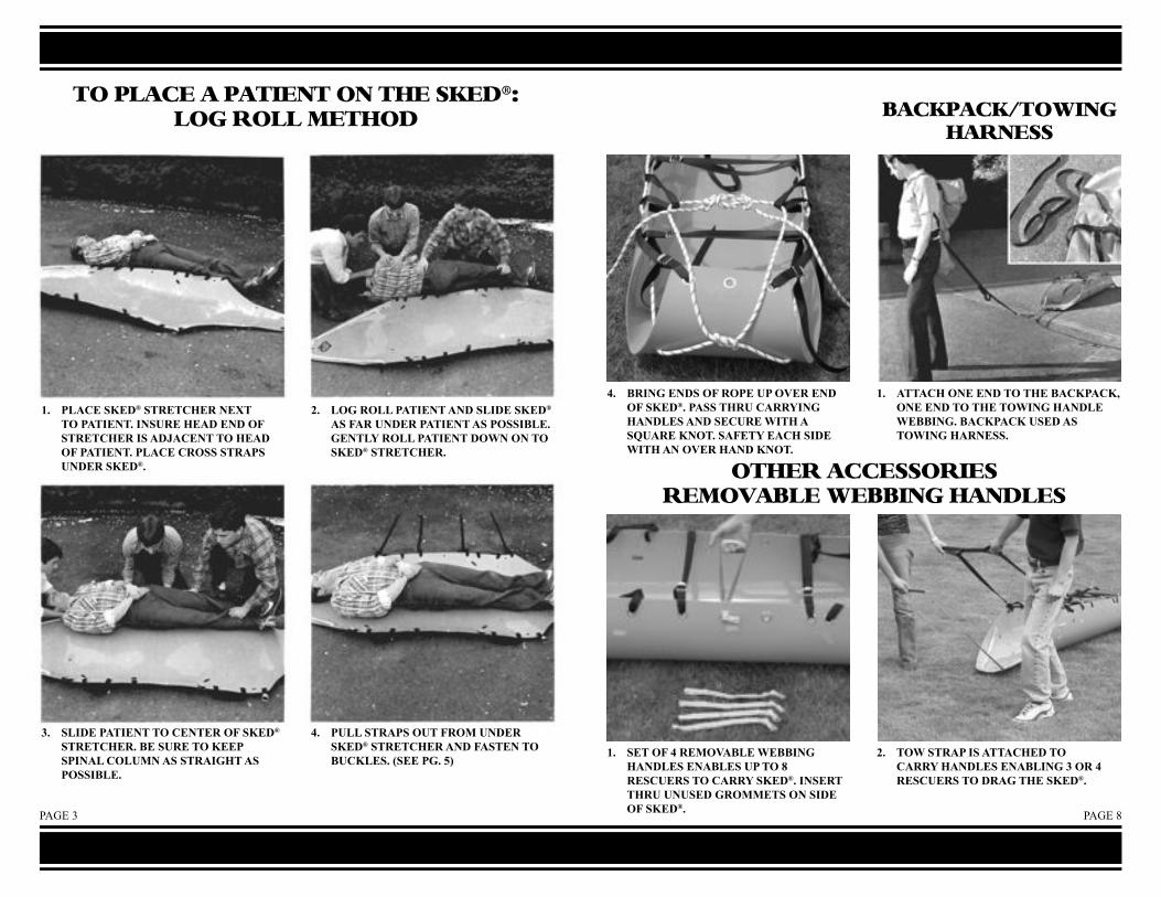
!"#$%& !"#$%'
!"# $%&'(#)*(+,#)-.(-'/(.#0(1-#-2#$&-3(0-"#30)4.(#/(&+#(0+#25#)-.(-'/(.#3)#&+6&'(0-#-2#/(&+#25#$&-3(0-"#$%&'(#'.2))#)-.&$)#40+(.#)*(+,"
7"# %28#.2%%#$&-3(0-#&0+#)%3+(#)*(+,#&)#5&.#40+(.#$&-3(0-#&)#$2))39%("#8(0-%:#.2%%#$&-3(0-#+2;0#20#-2#)*(+,#)-.(-'/(."
<"# )%3+(#$&-3(0-#-2#'(0-(.#25#)*(+,#)-.(-'/(."#9(#)4.(#-2#*(($#)$30&%#'2%4=0#&)#)-.&38/-#&)#$2))39%("
>"# $4%%#)-.&$)#24-#5.2=#40+(.#)*(+,#)-.(-'/(.#&0+#5&)-(0#-2#94'*%()"#?)((#$8"#@A
!"#$%&'(#&#$&!)(*!#"*#!+(#,-(./0%"1#2"%%#3(!+".
>"# 9.308#(0+)#25#.2$(#4$#2B(.#(0+#25#)*(+,"#$&))#-/.4#'&..:308#/&0+%()#&0+#)('4.(#;3-/#&#)C4&.(#*02-"#)&5(-:#(&'/#)3+(#;3-/#&0#2B(.#/&0+#*02-"
!"# &--&'/#20(#(0+#-2#-/(#9&'*$&'*D#20(#(0+#-2#-/(#-2;308#/&0+%(#;(99308"#9&'*$&'*#4)(+#&)#-2;308#/&.0())"
!"# )(-#25#>#.(=2B&9%(#;(99308#/&0+%()#(0&9%()#4$#-2#E#.()'4(.)#-2#'&..:#)*(+,"#30)(.-#-/.4#404)(+#8.2==(-)#20#)3+(#25#)*(+,"
7"# -2;#)-.&$#3)#&--&'/(+#-2#'&..:#/&0+%()#(0&9%308#<#2.#>#.()'4(.)#-2#+.&8#-/(#)*(+,"
4&'-$&'-5!"6)*1#+&2*(,,
"!+(2#&''(,,"2)(,#2(3"7&4%(#6(44)*1#+&*.%(,

!"#$%& !"#$%'%
!"# $%&'('%)#*%%(#+),#%*#&-+,.#&(/+(01+/#2(#1+2,#%*#$2('+)(
3"# 124+#%)+#/+&05+/#&(/2,,6+#&-+,.#2),#&5$$%/(#$2('+)(+2,7#)+0-#2),#&1%56,+/&"
8"# 9/2&$#*%%(#&(/2$&#%*#&-+,.#&(/+(01+/#2),#&6',+#&-+,.#5),+/#$2('+)("
:"# 0+)(+/#$2('+)(#%)#&-+,.#&(/+(01+/#2),#*2&(+)#&(/2$&#(%#;50-6+&#<&++#$9#=>"
!"#$%&'(#&#$&!)(*!#"*#!+(#,-(./0,%).(#1(!+".
!"# $2&&#+201#+),#%*#(1+#/%$+#(1/5#9/%??+((#(1+#1+2,#+),#%*#(1+#&(/+(01+/"#$566#(1+#-)%(#5$#292')&(#(1+#&(/+(01+/"
!2"#26(+/)2(+#?+(1%,#*%/#5&+#')#('91(#0%)*')+,#&$20+&"
3"# 0%)(')5+#*++,')9#/%$+#(1/5#5)5&+,#9/%??+(),#02//@')9#12),6+Ċ#(1+#A2@#(%#(1+#*%%(#+),#%*#(1+#&-+,."#')&5/+#;%(1#+),&#%*#/%$+#2/+#+4+)"
8"# $2&&#(1+#/%$+#+),&#(1/5#9/%??+((#(1+#*%%(#+),#%*#&-+,.#*/%?#(1+#')&',+#%5(A2/,"#('+#(1+#+),&#%*#(1+#/%$+#(%9+(1+/#A'(1#2#&B52/+#-)%("
2(3!)'&%#%)4!5.(,'(*!2#8C#*%%(#6+)9(1#%*#8DEF#&(2('0#-+/)?2)(6+#/%$+#A'(1#2#*'95/+#+'91(#-)%(#('+,#')#(1+#0+)(+/#'&+,#(%#0%)*'95/+#&-+,.#&(/+(01+/#*%/#4+/('026#6+*(D,+&0+)("

!"#$%& !"#$%'
!"# $%&'((#)*+,-#).&+./0+%,#(12#3(1."
4"# (53.#)5,+)#'3#)*+,-#1%,#31).+%#.0+#3'$&#/&'))#).&16)#'3#7$/*(+)#,5&+/.(2#'66')5.+#.0+#).&16)"
8"# 3++,#3''.#).&16)#.0&$#$%$)+,#9&'::+.)#1.#3''.#+%,#'3#)*+,-#1%,#31).+%#.'#7$/*(+)#;1)#)0'<%#5%#17'=+#60'.'>"
?"# )*+,-#).&+./0+&#<5.0#1((#).&16)#7$/*(+,#5%#6&'6+&#:1%%+&"
!"#$%"$&"'(%(")$*)+$,*'%-)'%.*&'$%"$/0123-'
!"# 5%)+&.#'%+#+%,#'3#0+1,#).&16#.0&$#(53.#)('.#1.#0+1,#+%,#'3#).&+./0+&"
4"# 7&5%9#).&16#$%,+&#)*+,-#1%,#.0&$#)('.#'%#'66')5.+#)5,+#'3#)*+,-"
8"# +@$1(5A+#).&16"#&+6+1.#6&'/+,$&+#<5.0#'.0+&#).&16#1.#3''.#+%,#'3#)*+,-"
?"# +@$1(5A+#1((#3'$&#).&16)#1%,#)+/$&+#.'#(1&9+#).++(#('/*5%9#/1&175%+&"
!".(4")%*3$3(,%5+-'1-)%.<'# %2('%# <+775%9# ).&16)# &1.+,# 1.# BCDDD# 6'$%,)# :7)# +1/0# 1&+# $)+,# 3'�'&5A'%.1(# (53.E,+)/+%."# 0+1,# ).&16# 5)# FG# )0'&.+&#.01%# 3''.# ).&16#1%,# 5)#$)+,#1.#0+1,#+%,#'3#).&+./0+&#'%(2"