Room Unit for Boiler Control QAA73 - ingrossoclimart.it · 6301 Zug . Switzerland ; ... The...
36
s Room Unit for Boiler Control With OpenTherm Interface User manual QAA73.210 Building Technologies Edition 1.0 Device series A CE1U2283en 16.08.2010
Transcript of Room Unit for Boiler Control QAA73 - ingrossoclimart.it · 6301 Zug . Switzerland ; ... The...

s
Room Unit for Boiler Control With OpenTherm Interface
User manual
QAA73.210
Building Technologies
Edition 1.0 Device series A CE1U2283en 16.08.2010

Siemens Switzerland Ltd Industry Sector Building Technologies Division Gubelstrasse 22 6301 Zug Switzerland Tel. +41 41-724 24 24 www.siemens.com/sbt
© 2010 Siemens Switzerland LtdSubject to change
2 / 36
Siemens Room Unit for Boiler Control CE1U2283en Building Technologies 16.08.2010

Table of contents
1 Overview ..................................................................................................5 1.1 Features ....................................................................................................5 1.2 Product liability ..........................................................................................6 1.3 Disposal ....................................................................................................6 2 Mounting and Installation.......................................................................6 2.1 Engineering...............................................................................................6 2.2 Installation .................................................................................................7 2.3 Electrical installation..................................................................................8 3 Commissioning .......................................................................................9 3.1 Operational faults ......................................................................................9 4 Handling.................................................................................................10 4.1 Operation ................................................................................................10 4.2 Programming room units parameters .....................................................15 4.2.1 User levels ..............................................................................................15 4.2.2 Overview of settings................................................................................16 4.3 Programming Siemens BMU parameters ...............................................18 5 Description of room unit settings .......................................................19 5.1 Time and day (TIME) ..............................................................................19 5.2 Time switch program (TSPHC, TSPCC, TSPHW)..................................19 5.2.1 Day selection...........................................................................................19 5.2.2 Switching times .......................................................................................20 5.3 Heating circuit (HEAT).............................................................................20 5.4 Cooling circuit (COOL)............................................................................27 5.5 Domestic hot water (DHW) .....................................................................27 5.6 Configuration (CONF) .............................................................................29 6 Functions ...............................................................................................30 6.1 Types of compensation ...........................................................................30 6.1.1 Weather compensation ...........................................................................30 6.1.2 Weather compensation with room influence...........................................30 6.1.3 Room compensation ...............................................................................31 6.1.4 Fix flow temperature setpoint..................................................................31 7 Dimensions............................................................................................32 8 Technical data .......................................................................................33 Index ................................................................................................................34
3 / 36
Siemens Room Unit for Boiler Control CE1U2283en Building Technologies Table of contents 16.08.2010

4 / 36
Siemens Room Unit for Boiler Control CE1U2283en Building Technologies Table of contents 16.08.2010

1 Overview
The QAA73.210 is a digital multi-functional room unit for one or 1 heating circuits and d.h.w. control.
Brief description
Boiler control delivers the outside temperature and other information to the QAA73.210 room unit via the OpenTherm communication interface. Based on the outside temperature, the room temperature and a number of other parameters, the interface calculates the required flow temperature setpoints for the heating circuits and transmits them to the boiler control. In addition, the d.h.w. temperature setpoint is transmitted to the boiler control.
The optimization functions offer energy savings without sacrificing comfort. The room sensor required for that purpose is integrated in the unit.
1.1 Features
• Operating sections (operating levels) based on ergonomic and functional
considerations Operating functions
• Clear assignment of basic functions: • Operating mode, setpoint adjustment and occupancy button • A number of actual values can be accessed via the Info button • Additional functions can be programmed via programming mode • Every setting or change is displayed and thus acknowledged • Heating circuit program with up to 4 heating periods per day can be selected on
an individual basis • Cooling circuit program with up to 4 heating periods can be selected on an
individual basis • D.h.w. program with up to 4 heating periods can be selected on an individual
basis • Holiday function • Special mode for setting the parameters of Siemens boiler control systems • Weather-compensated flow temperature control while giving consideration to the
building’s thermal dynamics Functions
• Weather-compensated flow temperature control with room compensation • Pure room temperature control • Effect of room temperature deviation can be adjusted • ECO functions (24-hour limit switch, automatic summer / winter changeover) • Room temperature switching differential for limiting the room temperature • Adjustable maximum limitation of the flow temperature (especially in connection
with floor heating systems) • Frost protection for the building • D.h.w. control with release and preselection of setpoint for the boiler controller • Legionella function • Integrated clock with a reserve of at least 12 hours • Communication with the boiler control via OpenTherm interface Other features • Power supply via OpenTherm bus
5 / 36
Siemens Room Unit for Boiler Control CE1U2283en Building Technologies Overview 16.08.2010

1.2 Product liability
• The products may only be used in building services plant and applications as described above
• When using the products, all requirements specified under "Technical data" must be observed
• The local regulations for electrical installation must be complied with
1.3 Disposal
The device is classified as waste electronic equipment in terms of the European Directive 2002/96/EC (WEEE) and should not be disposed of as unsorted muni-cipal waste.
The relevant national legal rules must be adhered to. Regarding disposal, use the systems setup for collecting electronic waste.
Observe all local and applicable laws.
2 Mounting and Installation 2.1 Engineering
• In the main living room or reference room Mounting location • The place of installation should be chosen so that the sensor can capture the
room temperature as accurately as possible, without being affected by direct solar radiation or other heating or cooling sources.
• Mounting height is about 1.5 meters above the floor • The unit can be fitted to most commercially available recessed conduit boxes or
directly on the wall.
6 / 36
Siemens Room Unit for Boiler Control CE1U2283en Building Technologies Mounting and Installation 16.08.2010

2.2 Installation
• Wall Mounting conditions • Boiler control panel • The controller may not be exposed to dripping water • Permissible ambient temperature: 0...50 °C
Wall mounting Step 1
Open the unit at the bottom and remove the base from the housing front.
Step 2 Connect the bus cable to the screw teminals.
Step 3 Fit the base to the wall with the help of screws.
Step 4 Engage the housing front at the top of the base and close the unit to the bottom.
7 / 36
Siemens Room Unit for Boiler Control CE1U2283en Building Technologies Mounting and Installation 16.08.2010

2.3 Electrical installation
The local regulations for electrical installations must be complied with. Regulations for installation
Connection diagram
12
1 2
COA COB
OpenTherm terminal A (interchangeable) OpenTherm terminal B (interchangeable)
23 mA max
8 / 36
Siemens Room Unit for Boiler Control CE1U2283en Building Technologies Mounting and Installation 16.08.2010

3 Commissioning
Prior to commissioning the controller, make the following checks: Prerequisites
• Correct mounting • Correct connection to OpenTherm bus • Enduser parameters are set as required • Heating engineer parameters are set in compliance with plant requirements At first power up or after a long off period (no power supply), "CLOW" is displayed on the LCD for some minutes. During this first period it is not possible to visualize or change parameters, the other functions are running. After some minutes a minimum back-up time is reached and the full functionality is available
3.1 Operational faults
No display on the room unit: Room unit Is the heating plant's main switch turned on? • Are the fuses in order? • Check the wiring • Boiler controller Does boiler control really have to operate? Boiler control does not
switch on • Press boiler control’s lock-out reset button • Check wiring and fuse of boiler control • Check the communication link to boiler control The room temperature does not agree with the required temperature level: Room temperature • Does the room temperature setpoint agree with the required temperature level? • Is the required operating mode indicated? • Are weekday, time of day and the displayed heating program correct?
(Info displays) • Has the heating curve slope been correctly set? • Check wiring of outside sensor • Has the "Nominal room temperature setpoint" with the "Parallel displacement of
the heating curve" been calibrated based on the effective room temperature? • Check boiler control D.h.w. is not being heated: D.h.w. • Has the button for d.h.w. heating been pressed? • Check setpoint of the d.h.w. temperature • Check d.h.w. function of boiler control
9 / 36
Siemens Room Unit for Boiler Control CE1U2283en Building Technologies Commissioning 16.08.2010

4 Handling 4.1 Operation
Operating elements
Operating element Function
Heating circuit operating mode button and associated symbols
Operating mode changes to: Automatic operation Continuous operation Protection Temporary function
D.h.w. operating mode button with associated symbol
D.h.w. heating ON / OFF
Setpoint buttons Heating Adjustment of room temperature setpoint
Setpoint buttons D.H.W. Adjustment of D.H.W. temperature setpoint
Info button Change of info display
Occupancy button Changeover of operating level
LCD Display of data and operating mode
Legend
DHW mode ON Space heating mode ON
Boiler operation for DHW heat demand
Boiler operation for heating circuit heat demand
Maintenance message Automatic operation
Holiday function Temporary function
Heating to Comfort setpoint Continuous operation
Heating to Reduced setpoint Protection
Boiler on
Display icons
10 / 36
Siemens Room Unit for Boiler Control CE1U2283en Building Technologies Handling 16.08.2010

11 / 36
Siemens Room Unit for Boiler Control CE1U2283en Building Technologies Handling 16.08.2010
Display of all symbols and segments.
Selection of space heating mode This setting is used to switch between the different operating modes. The selection made is indicated by a bar which appears below the respective symbol. Automatic mode controls the room temperature according to the time program. Characteristics of automatic mode: • Heating mode according to the time program • Temperature setpoints according to the heating program "Comfort setpoint" or "Reduced setpoint" • Protective functions active • Automatic summer / winter changeover and automatic 24-hour heating limit (ECO functions) active Continuous operation maintains the room temperature at the selected operating level.
Characteristics of continuous operation: • Heating mode with no time program • Protective functions active • Automatic summer / winter changeover and 24-hour heating limit (ECO
functions) inactive in the case of continuous operation with Comfort setpoint When using Protection mode, the heating system is off, but it remains protected against frost (frost protection temperature) provided there is no power failure.
Characteristics of Protection: • Heating off • Temperature according to frost protection • Protective functions active • Automatic 24-hour heating limit (ECO functions) active Cooling mode controls the room temperature in accordance with the time program. Characteristics of cooling mode: • Manual cooling mode • Cooling mode based on time program • Temperature setpoint based on "Comfort setpoint" or "Reduced setpoint"
Display
Automatic mode
Continuous operation
Protection
Cooling mode (if activated)

12 / 36
Siemens Room Unit for Boiler Control CE1U2283en Building Technologies Handling 16.08.2010
- / +
- / +
Selecting the DHW heating mode
he button is used to switch DHW heating mode on and off.
On HW is heated according to the selected switching program. A setpoint is
• HW heating
his function allows to set a temporary setpoint.
ting mode button for at least 3
int remins active during 55 minutes -> tap symbol is blinking.
To disactivate the function before the end of the 55 min press DHW button if
he QAA73.110 has no frost protection function for d.h.w. heating. Frost protection
Adjusting the room temperature setpoint "tAMB"
ush the + /– buttons to increase or decrease the Comfort setpoi
Adjusting the DHW temperature setpoint "HW SP"
ush the + /– buttons to increase or decrease the Nominal set
Presence button
you do not use the rooms for a certain period of time, you can
d again, press again the presence button to resume
tton is only active in automatic operation n according to the
uring the holiday period, the heating circuit operating level changes
between 10 minutes and 45 days.
utton
DHW heating mode
DHW shower
Notes
T •
The Dgenerated based on the demand for heat and the settings and passed on to theBMU. Off No D
TTriggering is effected by keeping the DHW operaseconds. The setpo •• The d.h.w. operating mode and the different d.h.w. functions are active only
supported by boiler control and if communicated in OpenTherm Plus mode Tfor d.h.w. must be ensured by boiler control.
P nt. The Reduced setpoint can be adjusted in programming level.
P point. The Reduced setpoint can be adjusted in programming level.
Ifpress the presence button to reduce the room temperature, thus saving heating energy. When the rooms are occupieheating operation.
• The presence bu• The current selection is active until the next switching actio
heating program takes place Dto frost protection. The setting range is• This function is only active in automatic mode. • The function can be cancelled by pressing any b
Caution

13 / 36
Siemens Room Unit for Boiler Control CE1U2283en Building Technologies Handling 16.08.2010
i Displaying information
arious data can be displayed by pressing the info button.
state,
isplay:
VDepending on the type of unit, configuration and operating some of the info lines listed below may not appear. D
Description Name Unit - Boiler temperature BOILR °C - Water pressure P BAR Bar - Outside temperature EXT T °C - Domestic hot water temperature DHW °C - Domestic hot water temperature 2 DHW 2 °C - Domestic hot water flow rate DHWFR n l/mi- Relative boiler power PWR % - Fan speed S FAN Rpm- Exhaust temperature T EXH °C - Return temperature RETUR °C - Calculated flow temperature setpoint CH SP °C
uring boiler operation it is
he room unit indicates faults that may have occurred in the unit itself or in the
a fault is indicated 'ERROR' and the error code followed by the letter 'E' are
set. They will be cleared only when rectified.
Dpossible to see the actual boiler modulation level on 4different levels.
Tsystem Ifvisualized in the display. These faults cannot be re
Error code Description
60 Room sensor
88 Communication
95 Clock
127 ella setpoint not reached 1) Legion
) Ca1 n be reset by pressin
epending on the type of boiler control, the room unit also displays other error he
Indication of faults
Other fault displays
g OK button Dcodes. For detailed information, please refer to the technical documentation of tboiler controller used.

14 / 36
Siemens Room Unit for Boiler Control CE1U2283en Building Technologies Handling 16.08.2010
During boiler lockout, 'ERROR'.and '>>>OK' are blinking alternatively and the error code followed by the letter 'E' are visualized in the display.
or resetting the BMU press the OK button by '>>>OK' are visualized in the
FIf the reset was successful 'RESET' followeddisplay.
activated / deactivated on the BMU QAA
activated / deactivated on the BMU buttons
Boiler lockout
Chimney sweep
Controller stop
IsBoiler temperature is visualized on the IsModulation level can be set by up down
2 seconds
2 seconds

4.2 Programming room units parameters
Button Description
1
Press the Info button for at least 3 seconds. This will take you directly to the programming level "Enduser".
2 The display shows a number of operating pages. Press the line selection buttons to select the required operating page. To confirm, press OK.
3 The display shows a number of operating pages. Press the line selection buttons to select the required operating line. To confirm, press OK.
4 The display shows the value flashing. Press the line selection buttons until value is correct. To confirm, press OK
5
By pressing the ESC button, you come back to operating page selection.
6
By pressing the ESC button, you leave the programming level.
Setting
If no button is pressed for about 1 minutes, the room unit will automatically leave programming level.
Note
4.2.1 User levels
The user levels only allow authorized user groups to make settings. To reach the required user level, proceed as follows: Buttons Explanation
1
Press the Info button for at least 3 seconds. This will take you directly to the programming level "Enduser".
2
Press the Info button for at least 3 seconds. This will take you to the user level selection.
3 You are now given a choice of user levels. Press the line selection buttons to select the required user level. To confirm, press OK. You are now on the required user level.
The following user levels are available
USR = End user INST = Heating engineer OEM = OEM
To reach the OEM level, the relevant code must be entered.
15 / 36
Siemens Room Unit for Boiler Control CE1U2283en Building Technologies Handling 16.08.2010
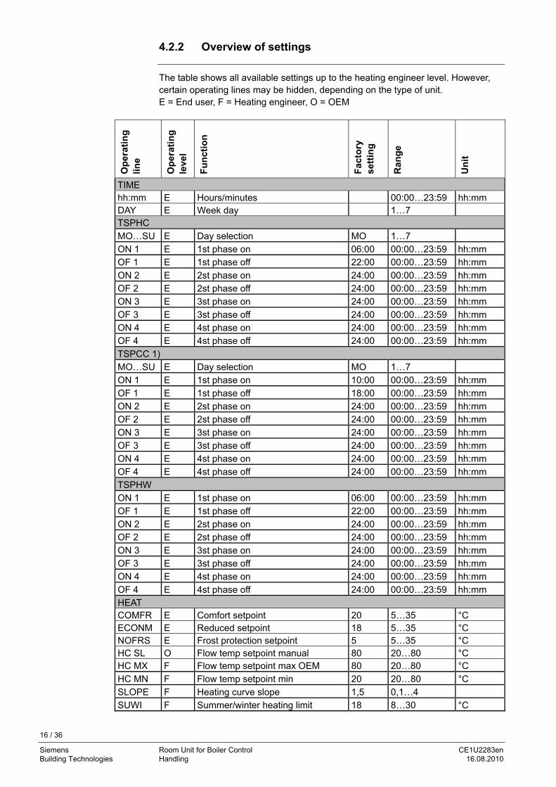
4.2.2 Overview of settings
The table shows all available settings up to the heating engineer level. However, certain operating lines may be hidden, depending on the type of unit. E = End user, F = Heating engineer, O = OEM
Op
erat
ing
lin
e
Op
erat
ing
le
vel
Fu
nct
ion
Fac
tory
se
ttin
g
Ran
ge
Un
it
TIME hh:mm E Hours/minutes 00:00…23:59 hh:mm DAY E Week day 1…7 TSPHC
MO…SU E Day selection MO 1…7
ON 1 E 1st phase on 06:00 00:00…23:59 hh:mm
OF 1 E 1st phase off 22:00 00:00…23:59 hh:mm
ON 2 E 2st phase on 24:00 00:00…23:59 hh:mm
OF 2 E 2st phase off 24:00 00:00…23:59 hh:mm
ON 3 E 3st phase on 24:00 00:00…23:59 hh:mm
OF 3 E 3st phase off 24:00 00:00…23:59 hh:mm
ON 4 E 4st phase on 24:00 00:00…23:59 hh:mm
OF 4 E 4st phase off 24:00 00:00…23:59 hh:mm
TSPCC 1)
MO…SU E Day selection MO 1…7
ON 1 E 1st phase on 10:00 00:00…23:59 hh:mm
OF 1 E 1st phase off 18:00 00:00…23:59 hh:mm
ON 2 E 2st phase on 24:00 00:00…23:59 hh:mm
OF 2 E 2st phase off 24:00 00:00…23:59 hh:mm
ON 3 E 3st phase on 24:00 00:00…23:59 hh:mm
OF 3 E 3st phase off 24:00 00:00…23:59 hh:mm
ON 4 E 4st phase on 24:00 00:00…23:59 hh:mm
OF 4 E 4st phase off 24:00 00:00…23:59 hh:mm
TSPHW
ON 1 E 1st phase on 06:00 00:00…23:59 hh:mm
OF 1 E 1st phase off 22:00 00:00…23:59 hh:mm
ON 2 E 2st phase on 24:00 00:00…23:59 hh:mm
OF 2 E 2st phase off 24:00 00:00…23:59 hh:mm
ON 3 E 3st phase on 24:00 00:00…23:59 hh:mm
OF 3 E 3st phase off 24:00 00:00…23:59 hh:mm
ON 4 E 4st phase on 24:00 00:00…23:59 hh:mm
OF 4 E 4st phase off 24:00 00:00…23:59 hh:mm
HEAT COMFR E Comfort setpoint 20 5…35 °C ECONM E Reduced setpoint 18 5…35 °C NOFRS E Frost protection setpoint 5 5…35 °C HC SL O Flow temp setpoint manual 80 20…80 °C HC MX F Flow temp setpoint max OEM 80 20…80 °C
HC MN F Flow temp setpoint min 20 20…80 °C
SLOPE F Heating curve slope 1,5 0,1…4
SUWI F Summer/winter heating limit 18 8…30 °C
16 / 36
Siemens Room Unit for Boiler Control CE1U2283en Building Technologies Handling 16.08.2010
17 / 36
Siemens Room Unit for Boiler Control CE1U2283en Building Technologies Handling 16.08.2010
Op
erat
ing
lin
e
Op
erat
ing
le
vel
Fu
nct
ion
Fac
tory
se
ttin
g
Ran
ge
Un
it
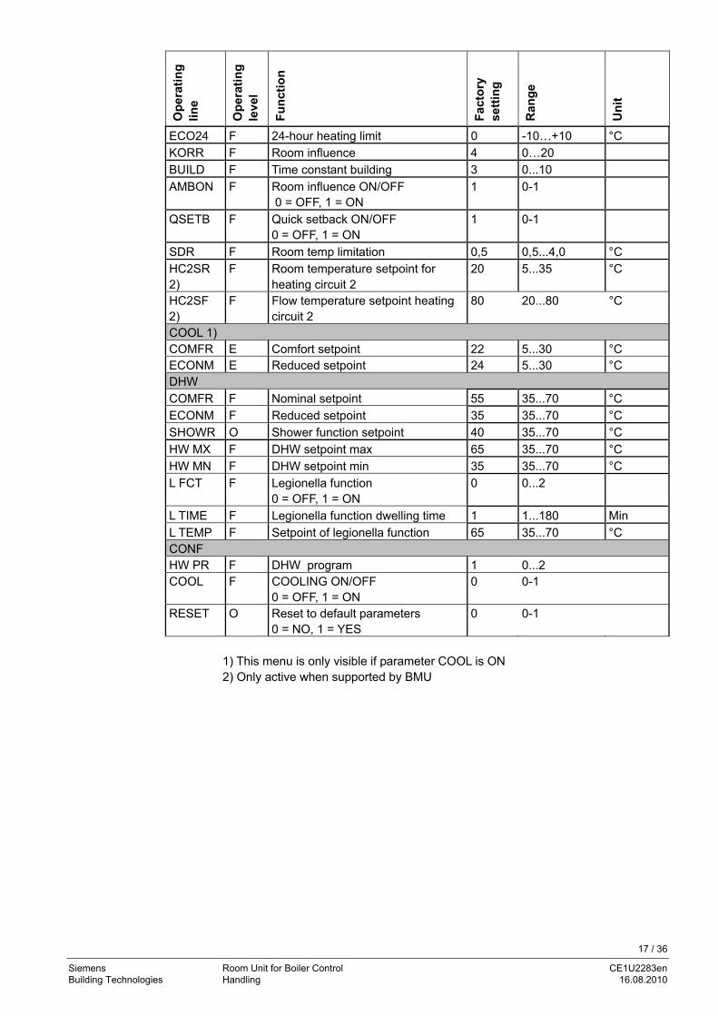
ECO24 F 24-hour heating limit 0 -10…+10 °C
KORR F Room influence 4 0…20
BUILD F Time constant building 3 0...10
AMBON F Room influence ON/OFF 0 = OFF, 1 = ON
1 0-1
QSETB F Quick setback ON/OFF 0 = OFF, 1 = ON
1 0-1
SDR F Room temp limitation 0,5 0,5...4,0 °C
HC2SR 2)
F Room temperature setpoint for heating circuit 2
20 5...35 °C
HC2SF 2)
F Flow temperature setpoint heating circuit 2
80 20...80 °C
COOL 1) COMFR E Comfort setpoint 22 5...30 °C ECONM E Reduced setpoint 24 5...30 °C DHW
COMFR F Nominal setpoint 55 35...70 °C
ECONM F Reduced setpoint 35 35...70 °C
SHOWR O Shower function setpoint 40 35...70 °C
HW MX F DHW setpoint max 65 35...70 °C
HW MN F DHW setpoint min 35 35...70 °C
L FCT F Legionella function 0 = OFF, 1 = ON
0 0...2
L TIME F Legionella function dwelling time 1 1...180 Min
L TEMP F Setpoint of legionella function 65 35...70 °C CONF HW PR F DHW program 1 0...2 COOL F COOLING ON/OFF
0 = OFF, 1 = ON 0 0-1
RESET O Reset to default parameters 0 = NO, 1 = YES
0 0-1
1) This menu is only visible if parameter COOL is ON 2) Only active when supported by BMU
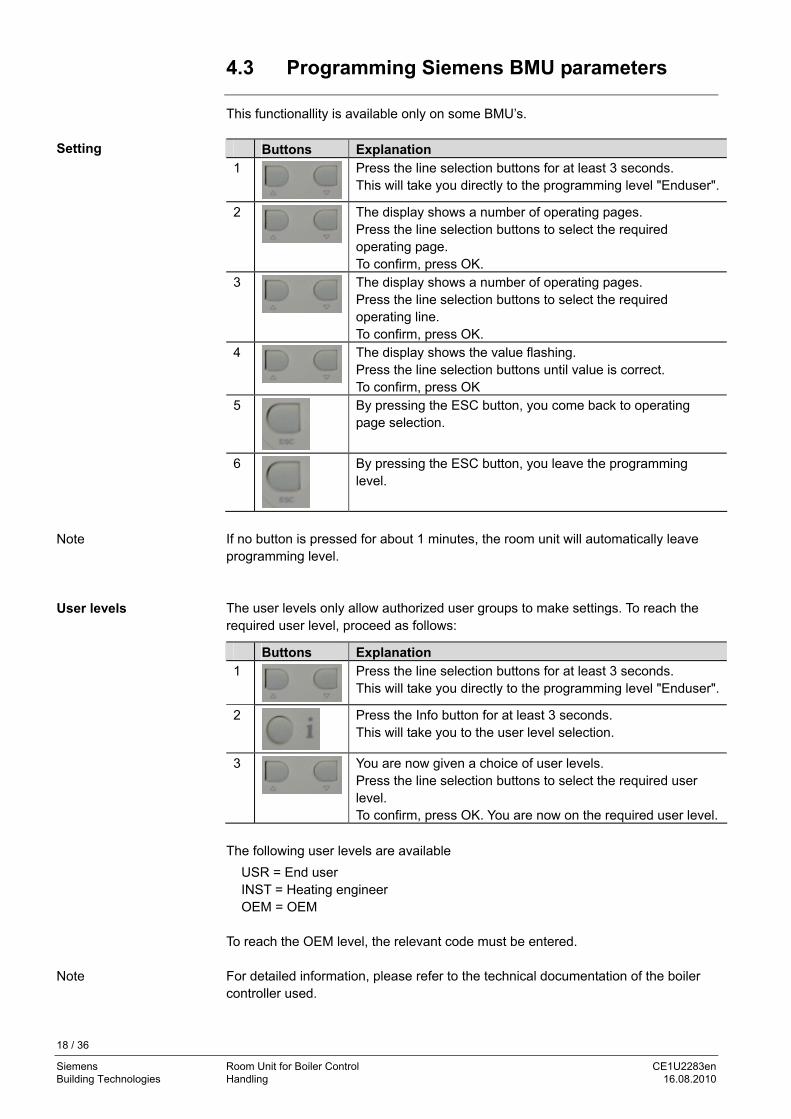
4.3 Programming Siemens BMU parameters
This functionallity is available only on some BMU’s. Buttons Explanation 1 Press the line selection buttons for at least 3 seconds.
This will take you directly to the programming level "Enduser".
2 The display shows a number of operating pages. Press the line selection buttons to select the required operating page. To confirm, press OK.
3 The display shows a number of operating pages. Press the line selection buttons to select the required operating line. To confirm, press OK.
4 The display shows the value flashing. Press the line selection buttons until value is correct. To confirm, press OK
5
By pressing the ESC button, you come back to operating page selection.
6
By pressing the ESC button, you leave the programming level.
Setting
If no button is pressed for about 1 minutes, the room unit will automatically leave programming level.
Note
The user levels only allow authorized user groups to make settings. To reach the User levels required user level, proceed as follows:
Buttons Explanation 1 Press the line selection buttons for at least 3 seconds.
This will take you directly to the programming level "Enduser".
2
Press the Info button for at least 3 seconds. This will take you to the user level selection.
3 You are now given a choice of user levels. Press the line selection buttons to select the required user level. To confirm, press OK. You are now on the required user level.
The following user levels are available
USR = End user INST = Heating engineer OEM = OEM
To reach the OEM level, the relevant code must be entered. For detailed information, please refer to the technical documentation of the boiler controller used.
Note
18 / 36
Siemens Room Unit for Boiler Control CE1U2283en Building Technologies Handling 16.08.2010
5 Description of room unit settings 5.1 Time and day (TIME)
To ensure proper functioning of the heating program, the time switch with the time of day and the weekday must be correctly set.
Lines (hh:mm, DAY)
Time of day and weekday are important, ensuring that the heating program, the cooling program and the d.h.w. programoperate as required.
5.2 Time switch program (TSPHC, TSPCC, TSPHW)
5.2.1 Day selection
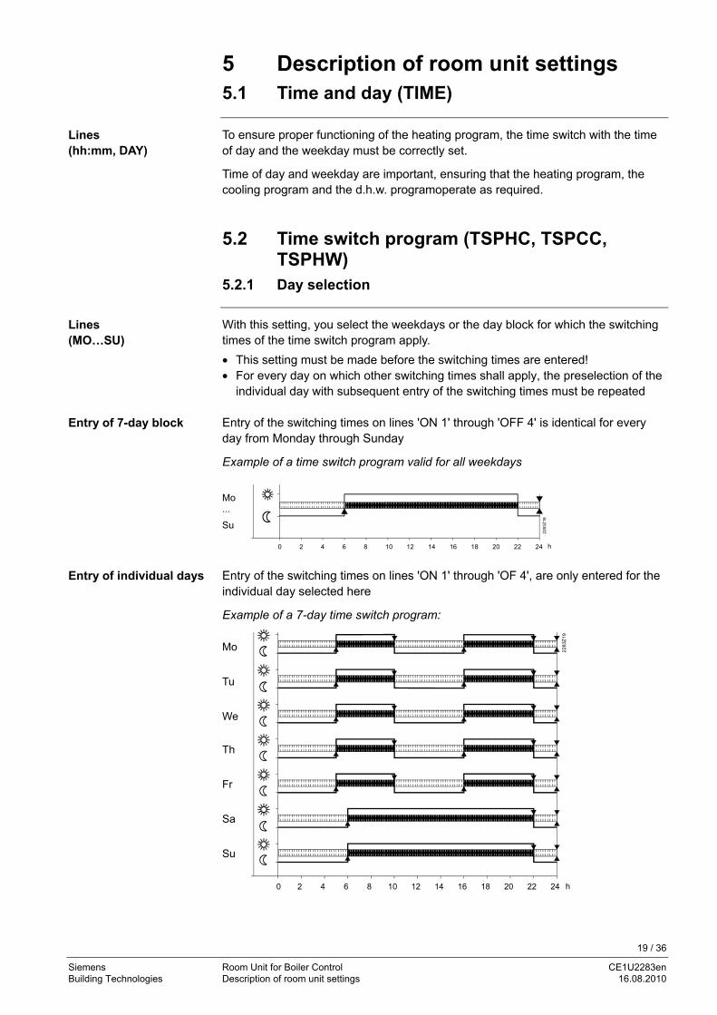
With this setting, you select the weekdays or the day block for which the switching times of the time switch program apply.
Lines (MO…SU)
• This setting must be made before the switching times are entered! • For every day on which other switching times shall apply, the preselection of the
individual day with subsequent entry of the switching times must be repeated Entry of the switching times on lines 'ON 1' through 'OFF 4' is identical for every day from Monday through Sunday
Entry of 7-day block
Example of a time switch program valid for all weekdays
Mo ...
Su
0 2 4 6 8 10 12 14 16 18 20 22 24 h2
283
Z18
Entry of the switching times on lines 'ON 1' through 'OF 4', are only entered for the individual day selected here
Entry of individual days
Example of a 7-day time switch program: Mo Tu We
Th Fr Sa Su
0 2 4 6 8 10 12 14 16 18 20 22 24 h
22
83Z
19
19 / 36
Siemens Room Unit for Boiler Control CE1U2283en Building Technologies Description of room unit settings 16.08.2010

First, choose the 7-day block to enter the switching times required for the majority of days; then, select the individual days to make the required adjustments.
Tip
5.2.2 Switching times
This setting defines the switching times for space heating and d.h.w. heating. The temperature setpoints of the 2 heating circuits and the d.h.w. usage times change at the times set.
Lines (ON 1 ...OF 4)
First, select the weekday for which the switching times shall be entered! Important
5.3 Heating circuit (HEAT)
In comfort operation, the comfort room temperature setpoint is maintained. Comfort room temperature setpoint (COMFR)
The comfort room temperature setpoint is adjusted with the buttons for the comfort temperature, which are located on the controller front for direct access by the user. When a button is pressed, the current room temperature setpoint is displayed and – when pressed further – readjusted.
0 2 4 6 8 10 12 14 16 18 20 22 24 35 °C
228
3Z07
6
5
Room temperature setpoint setting ranges
5 Reduced room temperature setpoint (ECONM) 6 Frost protection setpoint of the room temperature (NOFRS) When the comfort room temperature setpoint is active, the rooms will be heated according to the adjustment made with the setpoint buttons. The adjustment made with the buttons is only active in automatic and continuous operation. The comfort phases depend on the settings made on lines ‘ON 1’ through ‘OF 4’. Example
Mo ...
Su
0 2 4 6 8 10 12 14 16 18 20 22 24 h
2283
Z08
Comfort temperature and reduced temperature phases for heating circuit.
20 / 36
Siemens Room Unit for Boiler Control CE1U2283en Building Technologies Description of room unit settings 16.08.2010
The reduced room temperature setpoint ensures a lower room temperature during the night, for instance, to save energy.
Reduced room temperature setpoint (ECONM)
It is not possible to set the reduced setpoint above the adjustment made on comfort room temperature setpoint.
During the reduced phases, the reduced room temperature setpoint is maintained. Any lower comfort temperature is given priority however. This function prevents the room temperature from falling below the adjusted frost protection setpoint.
Frost protection room temperature setpoint (NOFRS) This setting will change the frost protection setpoint of the room temperature.
Caution • This function is ensured only when the heating plant operates properly! • Frost protection for the boiler and the d.h.w. must be ensured by the boiler
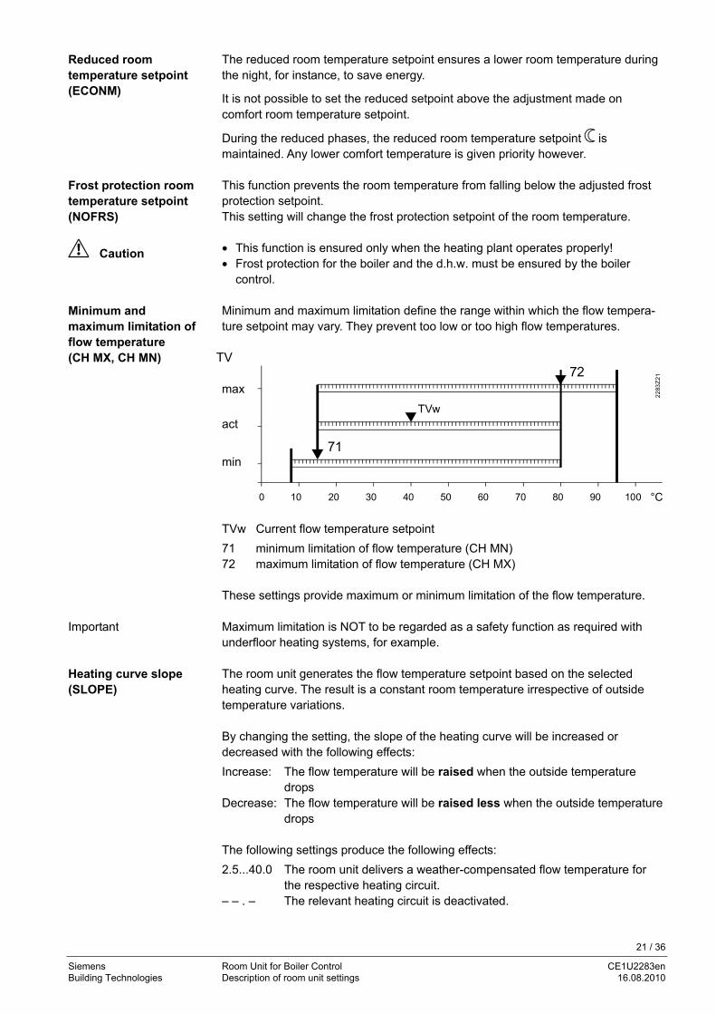
control. Minimum and maximum limitation define the range within which the flow tempera-ture setpoint may vary. They prevent too low or too high flow temperatures.
Minimum and maximum limitation of flow temperature (CH MX, CH MN)
TV max
act
min
0 10 20 30 40 50 60 70 80 90 100 °C
22
83Z
21
TVw
71
72
TVw Current flow temperature setpoint
71 minimum limitation of flow temperature (CH MN) 72 maximum limitation of flow temperature (CH MX) These settings provide maximum or minimum limitation of the flow temperature.
Important Maximum limitation is NOT to be regarded as a safety function as required with underfloor heating systems, for example. The room unit generates the flow temperature setpoint based on the selected heating curve. The result is a constant room temperature irrespective of outside temperature variations.
Heating curve slope (SLOPE)
By changing the setting, the slope of the heating curve will be increased or decreased with the following effects:
Increase: The flow temperature will be raised when the outside temperature drops
Decrease: The flow temperature will be raised less when the outside temperature drops
The following settings produce the following effects:
2.5...40.0 The room unit delivers a weather-compensated flow temperature for the respective heating circuit.
– – . – The relevant heating circuit is deactivated.
21 / 36
Siemens Room Unit for Boiler Control CE1U2283en Building Technologies Description of room unit settings 16.08.2010

The programmed heating curve is based on a room setpoint of 20°C. If the room setpoint is adjusted, the heating curve automatically adapts to the new value.
Note
The summer / winter changeover temperature is the criterion for automatic summer / winter changeover of the heating plant.
Summer / winter changeover temperature (SUWI) It offers the following benefits:
• Fully automatic operation throughout the year • The heating will not be switched on when the outside temperature drops for
short periods of time • Additional savings function By changing the setting, the respective periods of time will be shortened or extended. The change will only affect the heating circuit.
Increase: Winter operation will start earlier Summer operation will start later .
Decrease: Winter operation will start later
Summer operation will start earlier To determine changeover, the setting of the summer / winter changeover temperature ( ± a fixed switching differential) is compared with the attenuated outside temperature. Heating OFF (from winter to summer) Taged > SuWi +1 °C Heating ON (from summer to winter) Taged < SuWi -1 °C
Note This function only acts in automatic mode.
22 / 36
Siemens Room Unit for Boiler Control CE1U2283en Building Technologies Description of room unit settings 16.08.2010

23 / 36
Siemens Room Unit for Boiler Control CE1U2283en Building Technologies Description of room unit settings 16.08.2010
ON
17
T
SuWi
TAged°C
H
OFF
t
2284
D04
en
SuWi +1 °C
SuWi -1 °C16
18
19
20
50 10 15
Legend TAged Attenuated outside
temperature SuWi Summer / winter
changeover temperature
T Temperature t Time in days H Heating
The 24-hour heating limit is used to switch the heating on and off in the course of the day, depending on the outside temperature. This function is used primarily during spring and autumn to respond to short-term temperature variations. Example:
Setting line e.g. Comfort setpoint (TRw) 22 °C 24-hour heating limit (THG) -3 °C Changeover temperature (TRw-THG) heating off = 19 °C
Switching differential (fixed) -1 °C Changeover temperature heating on = 18 °C
By changing the value entered, the respective heating periods will be shortened or extended.
Increase: Heating mode will start earlier, changeover to ECO later.
Decrease: Heating mode will start later, changeover to ECO earlier.
• The function is not active in operating mode "Continuously Comfort temperature" • To give consideration to the building’s thermal dynamics, the outside
temperature will be attenuated Defines the influence of room temperature setpoint deviations on the controlled system. The room influence can be activated and deactivated (operating line 75).
Changing this setting has the following impact:
Increase: Authority of room influence will increase Decrease: Authority of room influence will decrease
24-hour heating limit (ECO24)
Gain factor of room influence (KORR)
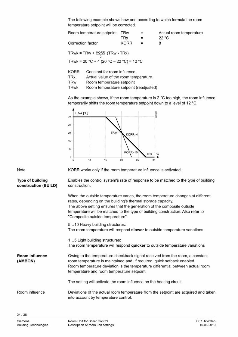
The following example shows how and according to which formula the room temperature setpoint will be corrected.
Room temperature setpoint TRw = Actual room temperature TRx = 22 °C Correction factor KORR = 8 TRwk = TRw + KORR
2 (TRw - TRx)
TRwk = 20 °C + 4 (20 °C – 22 °C) = 12 °C KORR Constant for room influence TRx Actual value of the room temperature TRw Room temperature setpoint TRwk Room temperature setpoint (readjusted) As the example shows, if the room temperature is 2 °C too high, the room influence temporarily shifts the room temperature setpoint down to a level of 12 °C.
30252015105
30
25
20
15
10
5
TRwk [°C]
KORR=4
TRx 22
84d0
3
KORR=10 °C
TRw
KORR works only if the room temperature influence is activated. Note Enables the control system's rate of response to be matched to the type of building construction.
Type of building construction (BUILD)
When the outside temperature varies, the room temperature changes at different rates, depending on the building's thermal storage capacity. The above setting ensures that the generation of the composite outside temperature will be matched to the type of building construction. Also refer to "Composite outside temperature".
5…10 Heavy building structures: The room temperature will respond slower to outside temperature variations 1…5 Light building structures: The room temperature will respond quicker to outside temperature variations Owing to the temperature checkback signal received from the room, a constant room temperature is maintained and, if required, quick setback enabled.
Room influence (AMBON)
Room temperature deviation is the temperature differential between actual room temperature and room temperature setpoint. The setting will activate the room influence on the heating circuit.
Room influence Deviations of the actual room temperature from the setpoint are acquired and taken into account by temperature control.
24 / 36
Siemens Room Unit for Boiler Control CE1U2283en Building Technologies Description of room unit settings 16.08.2010

To be able to use the control variant "Weather compensation with room influence", the following conditions must be satisfied:
• An outside sensor must be connected to boiler control • Room influence must be enabled to act on the relevant heating circuits • There may be no thermostatic radiator valves in the reference room (If such
valves are present, they must be set to their fully open position). During quick setback, the heating circuit pump is deactivated. Quick setback (QSETB)
• Function with room sensor: When using the room sensor, the function keeps the heating switched off until the room temperature has dropped to the level of the reduced setpoint or the frost level. When the room temperature has fallen to the reduced level or the frost level, the heating circuit pump will be activated and the mixing valve will be released.
• Function without room sensor:
Quick setback switches the heating off for a certain period of time, depending on the outside temperature and the building time constant.
Duration of quick setback when Comfort setpoint minus Reduced setpoint = 2 °C Example (e.g. Comfort setpoint = 20 °C and Reduced setpoint =18 °C)
Building time constant: Outside temperature composite: 0 2 5 10 15 20 50
15 °C 0 3.1 7.7 15.3 23 30.6 76.6 10 °C 0 1.3 3.3 6.7 10 13.4 33.5 5 °C 0 0.9 2.1 4.3 6.4 8.6 21.5 0 °C 0 0.6 1.6 3.2 4.7 6.3 15.8 -5 °C 0 0.5 1.3 2.5 3.8 5.0 12.5 -10 °C 0 0.4 1.0 2.1 3.1 4.1 10.3 -15 °C 0 0.4 0.9 1.8 2.6 3.5 8.8 -20 °C 0 0.3 0.8 1.5 2.3 3.1 7.7
Duration of quick setback in hours
• T Quick setback is possible with or without a room sensor It is used for room temperature limitation. This function prevent rooms from getting overheated.
Room temperature maximum limitation (SDR)
The switching differential for 2-position control will be changed. – – . – Switching differential is inactive
– The pump always remains activated Decrease: Switching differential will become smaller
– The pumps are switched on and off more often – The room temperature varies within a narrower band
Increase: Switching differential will become greater – The pumps are switched on and off less often – The room temperature varies within a wider band
25 / 36
Siemens Room Unit for Boiler Control CE1U2283en Building Technologies Description of room unit settings 16.08.2010

With pump heating circuits, the amount of heat supplied is controlled by switching the pumps on and off. This is accomplished with 2-position control by means of the room temperature's switching differential.
OFF
ONP
°CTRx
TRw+SDR
2371
D02
TRw
t
Legend TRx Actual value of the room
temperature TRw Room temperature setpoint SDR Switching differential of room
temperature ON Switch-on point OFF Switch-off point t Time P Pump
Pump ON TRx = TRw Pump OFF TRx = TRw + SDR
°C
ON
Legend TRx Actual value of the room
temperature
TRw Room temperature setpoint
SDR Switching differential of room temperature
P Pump (ON / OFF)
w Setpoint
Switch-on point
Switch-off point
The heating circuit pumps are controlled not directly by the QAA73.110, but by boiler control. For this reason, this functionality is not ensured by the room unit alone.
Note
Room temperature setpoint for heating circuit 2. Active only if supported by BMU. (HC2SR) Flow temperature setpoint for heating circuit 2. Active only if supported by BMU. (HC2SF)
26 / 36
Siemens Room Unit for Boiler Control CE1U2283en Building Technologies Description of room unit settings 16.08.2010

5.4 Cooling circuit (COOL)
In comfort operation, the comfort room temperature setpoint is maintained. Comfort room temperature setpoint (COMFR)
The comfort room temperature setpoint is adjusted with the buttons for the comfort temperature, which are located on the controller front for direct access by the user. When a button is pressed, the current room temperature setpoint is displayed and – when pressed further – readjusted. The reduced room temperature setpoint ensures a higher room temperature during the night, for instance, to save energy.
Reduced room temperature setpoint (ECONM)
5.5 Domestic hot water (DHW)
During nominal operation, the nominal d.h.w. setpoint is maintained. It is possible to use 2 different d.h.w. temperature setpoints.
Nominal DHW temperature setpoint (COMFR)
The temperature setpoint during normal d.h.w. operation will be changed.
0 10 20 30 40 50 60 70 80 90 100 120 130 140 °C
228
4Z
17
90 7 130
7 Nominal d.h.w. temperature setpoint (COMFR) 90 Reduced setpoint of the d.h.w. temperature (ECONM) 130 Maximum nominal setpoint of d.h.w. temperature (HW MX) Reduction of the d.h.w. temperatures outside main occupancy times. The time switch integrated in the room unit automatically switches between main and secondary occupancy times.
Reduced DHW temperature setpoint (ECONM)
D.h.w. is at a high temperature level only if required. This saves energy by reducing the temperature when not in use.
The temperature setpoint during reduced d.h.w. operation will be changed.
0 10 20 30 40 50 60 70 80 90 100 120 130 140 °C
2284
Z23
90 1307
7 Nominal d.h.w. temperature setpoint (COMFR) 90 Reduced setpoint of the d.h.w. temperature (ECONM) 130 Maximum nominal setpoint of d.h.w. temperature (HW MX)
27 / 36
Siemens Room Unit for Boiler Control CE1U2283en Building Technologies Description of room unit settings 16.08.2010

• Function for limiting the maximum settable nominal setpoint of the d.h.w. temperature.
Maximum DHW temperature setpoint (HW MX)
A d.h.w. setpoint maximum (TBWmax) of a BMU transmitted via OpenTherm is given priority and replaces that of the room unit (setting 130).
Note
Minimum DHW
temperature setpoint (HW MN)
• Function for limiting the minimum settable nominal setpoint of the d.h.w. temperature.
Note A d.h.w. setpoint minimum (TBWmin) of a BMU transmitted via OpenTherm is
given priority and replaces that of the room unit (setting 130). The legionella function ensures that the d.h.w. in the storage tank will periodically be raised to a temperature higher than nominal setpoint.
Legionella function (L FCT)
The setting activates or deactivates the legionella function. Entry:
O FF Function inactive
Weekly ON: Function is activated every Monday morning when d.h.w. is heated up for the first time and lasts a maximum of 2.5 hours. The d.h.w. is heated up to the adjusted legionella setpoint.
Daily Function is activated every day when d.h.w. is heated up for the first time and lasts a maximum of 2.5 hours. The d.h.w. is heated up to the adjusted legionella setpoint.
• If on the starting day of the legionella function, d.h.w. is not heated, or if the
function is aborted, it will be repeated the next day when d.h.w. is heated for the first time.
Notes
• This function is possible only when d.h.w. heating is released by the d.h.w. heating program.
The setpoint of the legionella function (operating line 92) is maintained for at least the period of time set here.
Dwelling time at legionella function setpoint (L TIME)
--- Function deactivated (no dwelling time)
The dwelling time starts as soon as the legionella setpoint is reached. During the entire dwelling time, the temperature may not fall below the legionella setpoint by more than the set BMU d.h.w. switching differential. The legionella function is terminated when this criterion is met. The setpoint of the legionella function is an adjustable temperature level to which the d.h.w. temperature is raised when the legionella function is activated.
Setpoint of the legionella function (L TEMP) The setting changes the d.h.w. setpoint during the period of time the d.h.w. is
heated up as a result of the legionella function.
28 / 36
Siemens Room Unit for Boiler Control CE1U2283en Building Technologies Description of room unit settings 16.08.2010

5.6 Configuration (CONF)
The setting activates or deactivates time switch program. TSP DHW enable (HW PR) 0: DHW OFF
1: DHW always ON 2: DHW time switch program active
The setting activates or deactivates the cooling function Cooling enable (COOL) All parameters can be reset to their default values. Default paramters
(RESET)
29 / 36
Siemens Room Unit for Boiler Control CE1U2283en Building Technologies Description of room unit settings 16.08.2010

6 Functions
The functions described below require no settings. They are performed automati-cally but have an impact on the plant.
Introduction
For the rectification of faults, planning and plant maintenance, it may therefore be very advantageous to know about their impact on plant operation.
6.1 Types of compensation
The room unit offers 3 types of compensation each of which generates the effective flow temperature setpoint in a different way. They are the following:
– Weather compensation – Weather compensation with room influence – Room compensation – Fix flow temperature setpoint
6.1.1 Weather compensation
With this type of compensation, the building’s heat losses are compensated by an adequate flow temperature.
Description
The colder the weather, the quicker the building cools down and the greater the heating circuit’s heat demand. With this type of compensation, it must be ensured that the heating curve is correctly set, because the room unit gets no feedback from the space whether the amount of heat supplied meets the demand of the users. The room influence (AMBON) must be set to "OFF" and, in addition, an outside sensor must be connected.
Prerequisites
6.1.2 Weather compensation with room influence
Compared to pure weather compensation, this type of compensation offers enhanced comfort because with the room influence, the room unit gets a feedback from the space.
Description
The room influence (AMBON) must be activated for the required heating circuits and, in addition, an outside sensor must be connected.
Prerequisites
The room influence acts on the room temperature setpoint. The deviation of setpoint / actual value of the room temperature is multiplied by the correction factor KORR/2 and added to the deviation from the room temperature setpoint in the opposite direction.
Room influence
Room influence acts:
• In the case of deviations of setpoint / actual value of the room temperature • With automatic or manual changeover to a higher or lower room temperature
setpoint
30 / 36
Siemens Room Unit for Boiler Control CE1U2283en Building Technologies Functions 16.08.2010

6.1.3 Room compensation
With pure room compensation, a PID control algorithm is activated. This is the preferred control mode if the room temperature is the only compensating variable available. The selected control algorithm gives consideration to both the actual value of the room temperature and the current slope (gradient). The P-part is generated by the control deviation, the D-part from the gradient of the room temperature. The I-part suppresses continuous deviations of setpoint / actual value.
Description
The room influence (AMBON) must be activated for the required heating circuits and, in addition, no outside sensor may be connected.
Prerequisites
The flow temperature and thus the room temperature are controlled as a function of the actual room temperature and its current development. For example, if the room temperature rises slightly, the flow temperature will immediately be reduced even if there is deviation of setpoint / actual value apparent yet. To prevent conti-nuous deviations, the I-part of PID control keeps the room temperature at the required level.
Effect
6.1.4 Fix flow temperature setpoint
The setpoint has to be set manually. Description The room influence (AMBON) must be set to "OFF" and, in addition, no outside sensor may be connected.
Prerequisites
31 / 36
Siemens Room Unit for Boiler Control CE1U2283en Building Technologies Functions 16.08.2010

7 Dimensions
Dimensions in mm
85
125.5
24
86
31
2283
M01
81.
5
130
Room unit
For special applications it is possible to integrate the device in the boiler panel. Panel cutout
The controller’s mounting dimensions are 81.5 x 125.5 mm.
The mechanical mounting facility allows the controller to be fitted in front panels having a thickness of 1 to 2 mm.
32 / 36
Siemens Room Unit for Boiler Control CE1U2283en Building Technologies Dimensions 16.08.2010
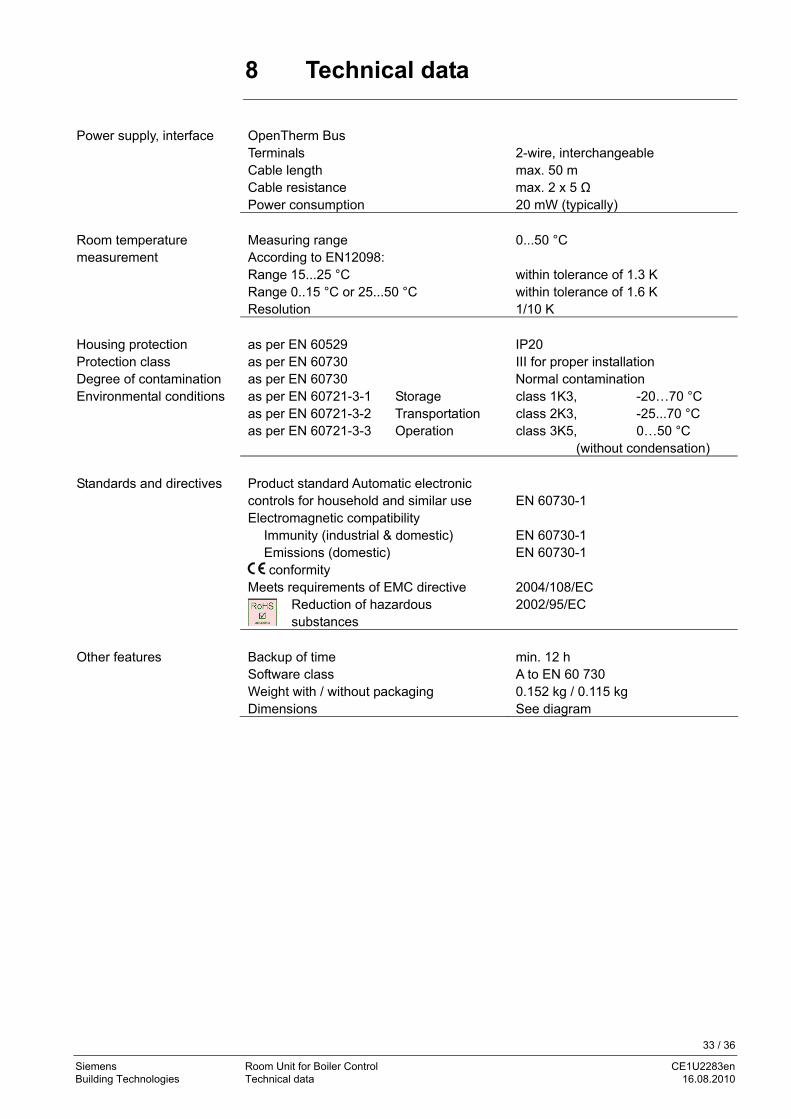
8 Technical data
Power supply, interface OpenTherm Bus Terminals 2-wire, interchangeable Cable length max. 50 m Cable resistance max. 2 x 5 Ω Power consumption 20 mW (typically)
Measuring range 0...50 °C Room temperature measurement According to EN12098: Range 15...25 °C within tolerance of 1.3 K Range 0..15 °C or 25...50 °C within tolerance of 1.6 K Resolution 1/10 K Housing protection as per EN 60529 IP20 Protection class as per EN 60730 III for proper installation Degree of contamination as per EN 60730 Normal contamination Environmental conditions as per EN 60721-3-1 Storage class 1K3, -20…70 °C as per EN 60721-3-2 Transportation class 2K3, -25...70 °C as per EN 60721-3-3 Operation class 3K5, 0…50 °C
(without condensation) Standards and directives Product standard Automatic electronic
controls for household and similar use EN 60730-1
Electromagnetic compatibility Immunity (industrial & domestic) EN 60730-1 Emissions (domestic) EN 60730-1 conformity Meets requirements of EMC directive 2004/108/EC
Reduction of hazardous substances
2002/95/EC
Other features Backup of time min. 12 h Software class A to EN 60 730 Weight with / without packaging 0.152 kg / 0.115 kg Dimensions See diagram
33 / 36
Siemens Room Unit for Boiler Control CE1U2283en Building Technologies Technical data 16.08.2010

34 / 36
Siemens Room Unit for Boiler Control CE1U2283en Building Technologies Index 16.08.2010
Index
D 32 28
E ............................................................. 6
H .................................................................. 6
L ................................................. 28
28
M 28 30
P 6
.................... 28
S 28
................................................ 22
T ....................................................... 33
W ......................................... 30
30 22
dimensions of cutout.............................................dwelling time legionella function ...........................
dwelling time......................................................
engineering
handling
legionella function
protection against legionella viruses
maximum d.h.w. setpoint (TBWmax)....................maximum limitation of setpoint rise.......................
product liability........................................................
setpoint of legionella function ...............................summer operation.
winter operation....................................................
technical data
weather compensationweather compensation with room influence .........

35 / 36
Siemens Room Unit for Boiler Control CE1U2283en Building Technologies 16.08.2010

Siemens Switzerland Ltd Industry Sector Building Technologies Division Gubelstrasse 22 6301 Zug Switzerland Tel. +41 41-724 24 24 www.siemens.com/sbt
© 2010 Siemens Switzerland Ltd Subject to change
36 / 36
Siemens Room Unit for Boiler Control CE1U2283en Building Technologies 16.08.2010