ROOM TEMPERATURE STRETCH FORMING OF SCALE … · ROOM TEMPERATURE STRETCH FORMING OF SCALE SPACE...
46
REPORT NO. CASD-NA-74-029 CONTRACT NAS8-30665 (NASA-cR-120365). ROO TEMPERATURE STRETCH N74-31343 FORMING. OF SCALE SPACE .SHUTTLE EXTERNAL TANK .DONE GORES. VOLUSE 1: TECHNICAL Final. Report (General Dynamics/Convair) Unclas p C $5.50 CSCL 22B G3/31 . 46210 ROOM TEMPERATURE STRETCH FORMING OF SCALE SPACE SHUTTLE EXTERNAL TANK DOME GORES VOLUME I + TECHNICAL FINAL REPORT GENERAL DYNAMICS Convair Division A. V~ ~~/piCA, https://ntrs.nasa.gov/search.jsp?R=19740023230 2018-07-20T20:36:16+00:00Z
Transcript of ROOM TEMPERATURE STRETCH FORMING OF SCALE … · ROOM TEMPERATURE STRETCH FORMING OF SCALE SPACE...
REPORT NO. CASD-NA-74-029CONTRACT NAS8-30665
(NASA-cR-120365). ROO TEMPERATURE STRETCH N74-31343
FORMING. OF SCALE SPACE .SHUTTLE EXTERNALTANK .DONE GORES. VOLUSE 1: TECHNICALFinal. Report (General Dynamics/Convair) Unclas
p C $5.50 CSCL 22B G3/31 . 46210
ROOM TEMPERATURE STRETCH FORMING OFSCALE SPACE SHUTTLE EXTERNAL
TANK DOME GORES
VOLUME I + TECHNICALFINAL REPORT
GENERAL DYNAMICSConvair Division
A. V~
~~/piCA,
https://ntrs.nasa.gov/search.jsp?R=19740023230 2018-07-20T20:36:16+00:00Z
REPORT NO. CASD-NAS-74-029
ROOM TEMPERATURE STRETCH FORMING OFSCALE SPACE SHUTTLE EXTERNAL
TANK DOME GORES
VOLUME I + TECHNICAL
FINAL REPORT
June 1974
Submitted toNational Aeronautics and Space AdministrationGEORGE C. MARSHALL SPACE FLIGHT CENTER
Science and Engineering LaboratoryHuntsville, Alabama 35812
Prepared byGENERAL DYNAMICS CONVAIR DIVISION
P.O. Box. 80847San Diego, California 92138
FOREWORD
This report was prepared by General Dynamics Convair Division under
Contract NAS8-30665 (Exhibit B) "Room Temperature Stretch Forming
of Scale Space Shuttle External Tank Dome Gores" for the George C.Marshall Space Flight Center of the National Aeronautics and SpaceAdministration. The work was administered by M. A. Oliver (A & PS-PR-RD) and monitored by Messrs. E. D. Minter (S & E-PE-MWP) andV. H. Yost (S & E-PE-MWP). C. L. Bennett was the program manager.
Volume I (technical) of the report was prepared by R. D. Blunck andD. E. Krantz, and the report was approved by C. L. Bennett. The pro-
duction flow chart and tooling requirements were contributed byR. E. Bruce.
Volume II of the report contains the cost study estimates required under
this contract. The cost estimates were prepared by L. J. Pierce,
J. A. Cherry and E. N. Yeaton, and the report was prepared byD. E. Krantz.
PRECEDING PAGE BLANK NOT FILMED
iii

TABLE OF CONTENTS
Section Page
1 INTRODUCTION 1-1
2 PHASE I - ROOM TEMPERATURE STRETCH FORMING OFONE-THIRD-SCALE EXTERNAL TANK BULKHEAD GORE 2-1
2.1 ROOM TEMPERATURE STRETCH FORMING 2-12.2 LONGITUDINAL STRETCH FORMING MACHINE
CAPABILITY AT CONVAIR 2-32.3 NUMERICAL CONTROL (N/C) MACHINING OF
GORE BLANKS 2-42.4 WELD STRENGTH VERIFICATION TESTS AND
GORE BLANK WELDING 2-4
2.5 PRE-FORMING THICKNESS INSPECTION 2-62.6 TRIMMING OF GORE BLANKS 2-9
2.7 ELONGATION GRIDDING OF GORE BLANKS 2-92.8 ONE-THIRD-SCALE GORE DIE AND
SUBSTRUCTURE 2-9
2.9 STRETCH FORMING OF ONE-THIRD-SCALEGORES 2-9
2.9. 1 Test Setup 2-132.9.2 Test 2-132.9. 3 Post-Forming Inspection 2-152.10 PACKAGING AND SHIPPING 2-292.11 CONCLUSIONS 2-29
3 PHASE II- PRODUCTION DIE DESIGN, TOOLING COST
STUDY, AND PRODUCTION COST STUDY 3-1
3.1 GENERAL INFORMATION 3-13.2 STRETCH FORM DIE DESIGN 3-33.3 TOOLING COST STUDY 3-53.4 PRODUCTION FLOW CHART 3-53.5 PRODUCTION COST STUDY 3-5
Appendix
COLD STRETCH FORMED BULKHEAD GORE DRAWING A-1
pRBCDING PAG BLANK NOT fL
V
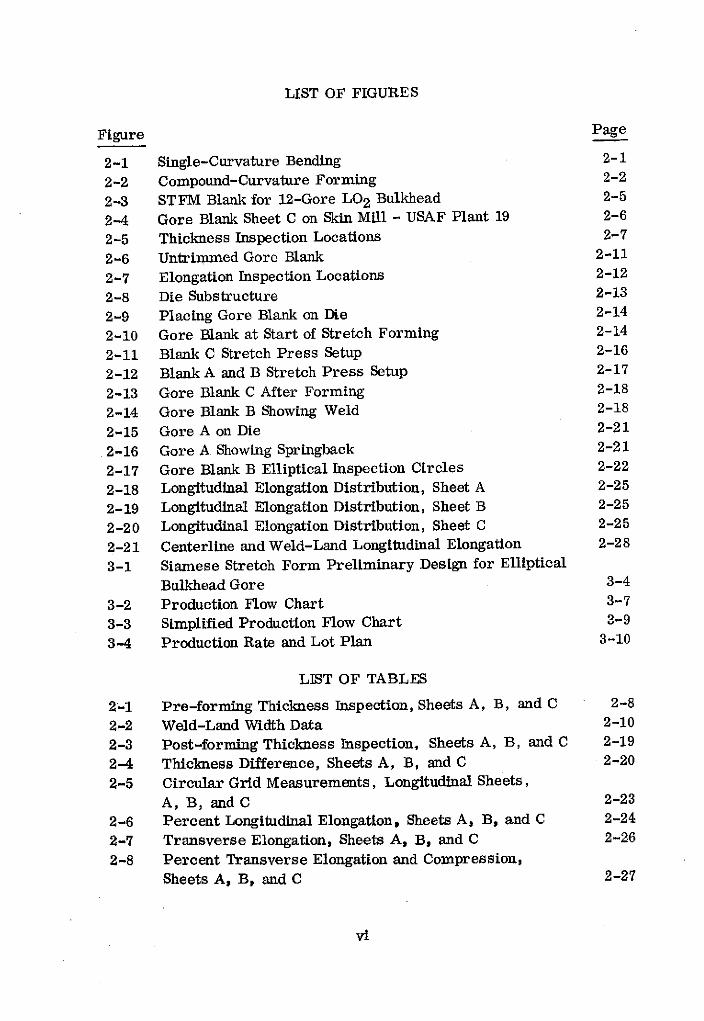
LIST OF FIGURES
Figure Page
2-1 Single-Curvature Bending 2-1
2-2 Compound-Curvature Forming 2-2
2-3 STFM Blank for 12-Gore LO2 Bulkhead 2-5
2-4 Gore Blank Sheet C on Skin Mill - USAF Plant 19 2-6
2-5 Thickness Inspection Locations 2-7
2-6 Untrimmed Gore Blank 2-11
2-7 Elongation Inspection Locations 2-12
2-8 Die Substructure 2-13
2-9 Placing Gore Blank on Die 2-14
2-10 Gore Blank at Start of Stretch Forming 2-14
2-11 Blank C Stretch Press Setup 2-16
2-12 Blank A and B Stretch Press Setup 2-17
2-13 Gore Blank C After Forming 2-18
2-14 Gore Blank B Showing Weld 2-18
2-15 Gore A on Die 2-21
2-16 Gore A Showing Springback 2-21
2-17 Gore Blank B Elliptical Inspection Circles 2-22
2-18 Longitudinal Elongation Distribution, Sheet A 2-25
2-19 Longitudinal Elongation Distribution, Sheet B 2-25
2-20 Longitudinal Elongation Distribution, Sheet C 2-25
2-21 Centerline and Weld-Land Longitudinal Elongation 2-28
3-1 Siamese Stretch Form Preliminary Design for Elliptical
Bulkhead Gore 3-4
3-2 Production Flow Chart 3-7
3-3 Simplified Production Flow Chart 3-9
3-4 Production Rate and Lot Plan 3-10
LIST OF TABLES
2-1 Pre-forming Thickness Inspection, Sheets A, B, and C 2-8
2-2 Weld-Land Width Data 2-10
2-3 Post-forming Thickness Inspection, Sheets A, B, and C 2-19
2-4 Thickness Difference, Sheets A, B, and C 2-20
2-5 Circular Grid Measurements, Longitudinal Sheets,
A, B, and C 2-23
2-6 Percent Longitudinal Elongation, Sheets A, B, and C 2-24
2-7 Transverse Elongation, Sheets A, B, and C 2-26
2-8 Percent Transverse Elongation and Compression,
Sheets A, B, and C 2-27
vi
SUMMARY
This document is the final technical report on "Room Temperature Stretch
Forming of Scale Space Shuttle External Tank Dome Gores" under Contract
NAS 8-30665 (Exhibit B). It gives an account of the performed tests, the re-sults, and an analysis of the results. It also gives an account of a productioncost study. The technical material is presented in Volume I of the report, andthe cost study data is presented in Volume II.
The Phase I objective of the program was to prove the feasibility of room tem-
perature stretch forming of approximate one-third scale bulkhead gores from
premachined 2219-T37 aluminum alloy blanks. Three gores were successfully
formed to an approximate one-third-scale, 12-gore, 355.6-cm (140-in.) diam-
eter polar cap configuration of atypical 838. 7-cm (330. 2-in.) diameter bulkhead,
thereby demonstrating feasibility. The three gores were shipped to NASA
MSFC and received by NASA, MSFC on June 21, 1974.
The Phase II cost study objectives were to: a) prepare a typical full-scale pro-
duction STFM die design, and determine the cost of all tooling required to
manufacture seven gore configurations at the required production rates, and,
b) determine the production cost per gore for the seven configurations at the re-
quired production rates to manufacture, package, and ship these gores to NASA's
Michoud Assembly Facility. All of the Phase II objectives were achieved.
vii

SECTION 1
INTRODUCTION
This report is an account of activities and data gathered in the Room Temperature
Stretch Forming of One-third Scale External Tank Bulkhead Gores for Space Shuttle
study, and a tooling design and production cost study.
The objectives of the studies were to:
a. Stretch form (at room temperature) three approximately one-third-scale external
tank (ET) dome gores from single sheets of 2219-T37 aluminum alloy, for Marshall
Space Flight Center testing and evaluation.
b. Design a full-scale production die, and determine the cost of all tooling required
to manufacture, using the room-temperature stretch forming (RTSF) process, ETdome gores at the required production rates.
c. Determine the cost per gore, at the required production rates, to manufacture,package, and ship these gores to NASA's Michoud Assembly Facility.
The program was divided into phases and tasks:
Phase I - Manufacture, Documentation, and Delivery of Three One-third-ScaleRoom Temperature Stretch Formed External Tank Dome Gores
Of particular concern in this study is the amount of material that must be trimmed
away after room temperature stretch forming. Reusable ends were welded on two
gores before forming, demonstrating material reduction possibilities. The 12 gore355.6 cm (140 in.) polar cap configuration was scaled down approximately one-third
and used for the stretch forming test.
Phase II - Production Die Design, Tooling Cost Study, and Production Cost Study
Task A - Production Die Design
Task B - Tooling Cost Study
Task C - Production Cost Study
1-1
SECTION 2
PHASE I - ROOM TEMPERATURE STRETCH FORMING OF
ONE-THIRD-SCALE EXTERNAL TANK BULKHEAD GORE
2.1 ROOM TEMPERATURE STRETCH FORMING
The bulkhead gore for the Space Shuttle External Tank is described by an ellipse rotated
about its minor axis.
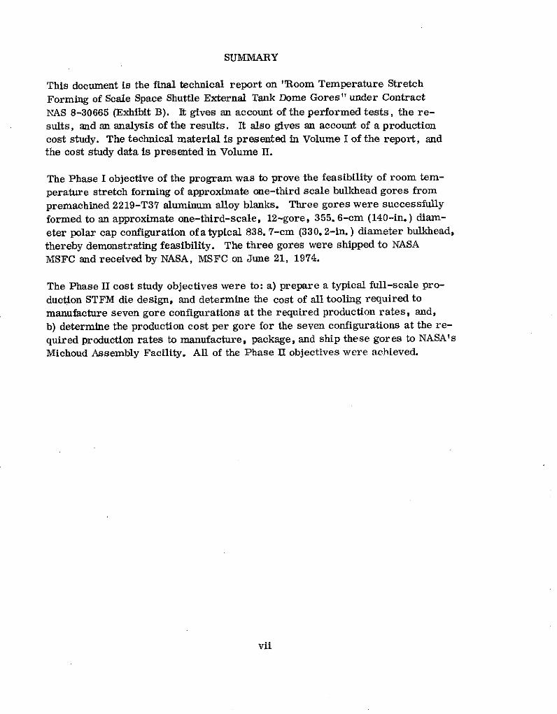
The longitudinal stretch forming process consists of two stages. The first is a wrapping
or single-curvature bending of the blank over the die, where the blank is in contact with
the crown of the die over the entire length. To impart this curvature permanently to the
blank, the steps shown in Figure 2-1 must occur.
For thin materials, such as those being considered for the bulkhead gores, the strain
required to accomplish this action is small in comparison with the strain required
during the second stage of forming.
STEPS
1 2 3{ TENSION TENSION TENSION
COMPRESSION
BENDING STRAIN UNIFORM STRAIN TO RESULT OF
THROUGH SHEET PRODUCE ZERO STRAIN STRAINS 1 & 2
THICKNESS ON COMPRESSION SIDE
4 5
EXTRA STRAIN TO TOTAL STRAIN REQUIRED TO
REACH YIELD STRAIN CAUSE PERMANENT SINGLE-ON COMPRESSION CURVATURE SHAPE BY STRETCH
SIDE FORMING
Figure 2-1. Single-Curvature Bending
2-1
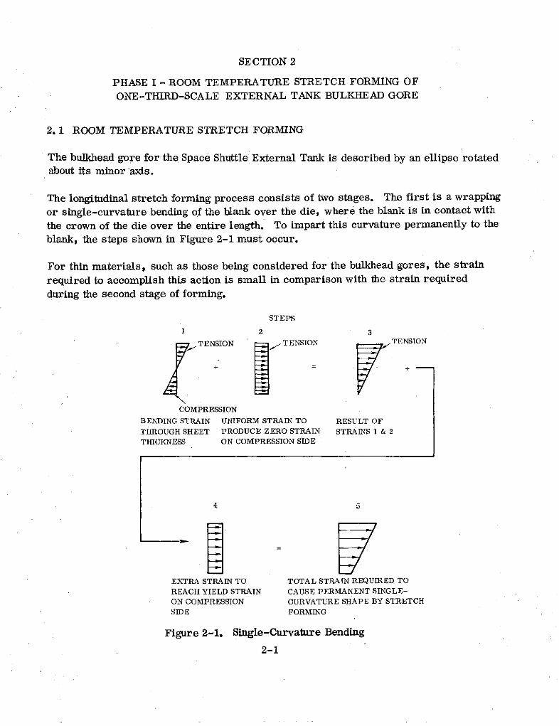
The second stage consists of stretching the material in contact with the die crown areaand allowing the side material to drop down with respect to the crown. Elongation re-quired to accomplish this forming is dependent on the die radius in the stretch formdirection and the height differential between the crown and the edge of the part as shownin Figure 2-2.
The last point along the edge to touch the die has the least elongation. If the stretchforming process were stopped just as this point touched, the elongation at this pointwould be zero. With the unloading of the blank, this point would spring away from thedie. To avoid this springback, the part must be further stretched to reach the materialyield strain in the edge element.
ISECTION AA A - 1
A
0 00
ZERO ELONGATION INEDGE AT TIME IT JUST rTOUCHES DIE
ELONGATION AT THE DIE CROWN FOR ELONGATION REQUIRED TO IMPARTCONSTANT LONGITUDINAL RADIUS: PERMIANENT SET EDGE:
h217r - 27 (r-h) h r- + eSr-h yield'1T (r-h) r-h
Figure 2-2. Compound-Curvature Forming
GORE BLANK SKIN AREA To reduce fabrication costs anddecrease stretch-pull tonnage
, . requirements, the blanks are
premachined. Basic blank thick-ness is determined by the maxi-
-- ** mum required weld land thickness.The blank is then machined, in the
WELD LAND flat, to produce the gore skin-weldFINAL EDGE TRiiM FOR GORE shape and thickness.
2-2

TRIMMED GORE BLANK
Further machining is required
to produce a relatively constantPOCKET cross-sectional area throughout
the stretch form length, and a--- pocket is machined at the base
-- CONSTANT CROSS-SECTIONAL end having the same cross-GORE BASE AREA EXISTS FOR THIS LENGTH sectional area.
The purpose of this pocketed area at the base of the gore is to allow the material tostretch in this area, thereby in effect, allowing a small amount of material draw tooccur in the center of the gore base end. If this pocket is not machined in the blank,no material draw will occur during stretch forming, and the amount of stretch in thecenter at the base end will be slightly higher. Previous gore stretch forming testswith and without the machined pocket have proven this to be true.
2.2 LONGITUDINAL STRETCH FORMING MACHINE CAPABILITY AT CONVAIR
The stretch forming press used to stretch form the three one-third-scale test goreswas a 500-ton Sheridan-Gray stretch press that is located at Building 5, Column C-16at the Kearny Mesa Plant, San Diego. It's versatility is shown in the following data:
Maximum Tensile Force 500 ton
Jaw Width 254 cm (100 inches) in seven segments
Jaw Travel 91.44 cm (36 inches) each jaw
Distance Between Jaws 243.84 cm (96 inches) minimum1259. 84 cm (496 inches) maximum
(The six outboard segments can be positioned to curve the jaws.)
Strain Rates 5. 08 to 101. 60 cm (2 to 40 inches) perminute
Number of Die Tables 3 (usually used together)
Die Table Size 60. 96 cm (20 inches) by 254 cm (100 inches)each
Longitudinal Die Table Capacity 182 cm (72 inches) minimum1097. 28 cm (432 inches) maximum
Die Table Vertical Travel 91. 44 cm (36 inches)
2-3
2.3 NUMERICAL CONTROL (N/C) MACHINING OF GORE BLANKS
The gore blanks were machined from 2219 aluminum alloy on hand at Convair. Two of
the sheets were mill processed 2219-T37 0.635 cm (0. 250 in.) thick by 152.4 cm (60
in.) wide by 304.8 cm (120 in.) long. The third sheet was 2219-T87 0. 635 cm (0.25
in.) by 121. 92 cm (48 in.) by 365. 76 cm (144 in.). The third sheet was re-solution
treated, quenched, and stretched 7% before machining. Although this sheet meets
MIL-A-8920 minimum properties, it is not typical of mill supplied 2219-T37 material.
Limited tensile data available indicates mill supplied 2219-T37 has 3 to 5% more avail-
able elongation than the material in the third sheet.
The blanks were milled to a scale factor of 838.7 cm (330.2 in.) full-size dome diam-
eter divided by 304.8 cm (120 in.) Atlas dome diameter or SF=2.75. Thus the blanks
are 36.3% of the full-scale gore. All dimensions were held to this scale except the
thickness dimensions. It was decided that the minimum thickness of the scaled gores
should be 0. 070 inch to avoid the possibility of failure due to reduced elongation in thin
sheets; therefore, the scale factor used for the material thickness is the minimum full-
size LO2 tank skin thickness of 0. 297 cm (0. 117 in.) divided by 0. 178 cm (0. 070 in.)
or SF= 1. 67. The tapered weld land thicknesses were also scaled down using the 1. 67SF. Thus, all blank thickness dimensions are 59. 8% of full size.
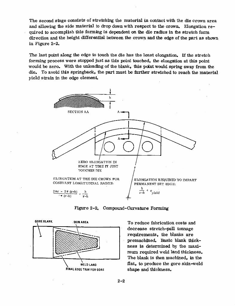
A flat layout drawing of the one-third-scale LO2 tank gore was given to the Numerical
Control (N/C) Department for preparation of the N/C program. Figure 2-3 shows the
gore blank layout giving both flat dimensions and thicknesses. The blanks were held
in place with a vacuum chuck plate on a Giddings and Lewis skin mill at USAF Plant 19.
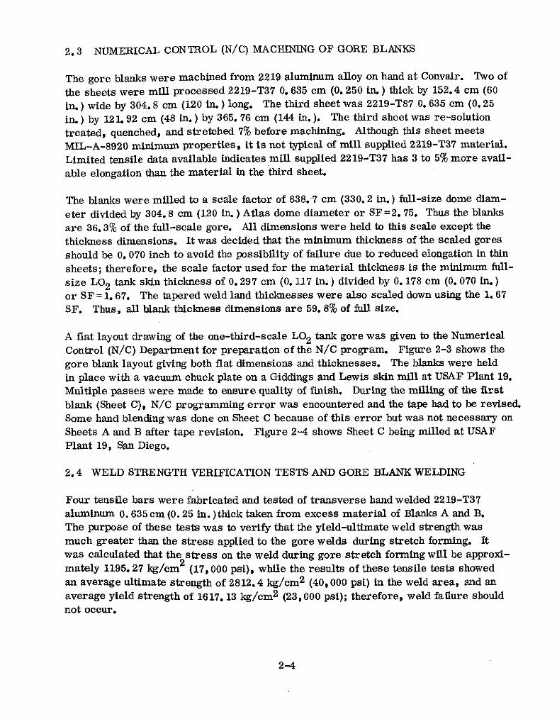
Multiple passes were made to ensure quality of finish. During the milling of the first
blank (Sheet C), N/C programming error was encountered and the tape had to be revised.
Some hand blending was done on Sheet C because of this error but was not necessary on
Sheets A and B after tape revision. Figure 2-4 shows Sheet C being milled at USAFPlant 19, San Diego.
2.4 WELD STRENGTH VERIFICATION TESTS AND GORE BLANK WELDING
Four tensile bars were fabricated and tested of transverse hand welded 2219-T37
aluminum 0. 635cm (0.25 in.)thick taken from excess material of Blanks A and B.The purpose of these tests was to verify that the yield-ultimate weld strength was
much greater than the stress applied to the gore welds during stretch forming. Itwas calculated that the stress on the weld during gore stretch forming will be approxi-
mately 1195.27 kg/cm 2 (17,000 psi), while the results of these tensile tests showed
an average ultimate strength of 2812.4 kg/cm2 (40,000 psi) in the weld area, and an
average yield strength of 1617. 13 kg/cm 2 (23,000 psi); therefore, weld failure shouldnot occur.
2-4

CONSTANT THICKNESS
74. 29 cm SKIN 123. 57 cm t3.81 cm
(29.25 IN.) (18. 65 IN.) (1.50 IN.) 1/4 IN. STOCK THICKNESS60.96c -m
(24.0 N.)
/ z'END OF TAPER
4.76. 20 mcm(1. 9 IN. R)
76.20 cm A TYP. A(30. 00 IN.)
(4.64cmI31.06cm84. 84 cm 66.04 cm (12.23 IN.)(33.40 IN.)(26 IN. R}
_________(26_ IN)R
74.11 cm(29. 2IN.)
SCALE 2. 54 cm =25. 4 cmp
SCALE I IN. = 10 IN.
20.96 cm 50.80 cm 2.54 cmi
(8.25 IN.) (20 IN.) (1 IN.) 364.49 cm WELD A & B ONLYI (143.5 IN.)
7. 62 cm
.332 cm ± .025 cm(3 IN. RTYP.
(0.131 IN. ± . 010 IN.) 123.57 em 3. 81 cm
CONSTANT T (48. 65 IN. 1 5I.9. 60 cm 108.81 cm A 2.03 cm N0.63 cm
3.78 IN. SKIN TAPER (42.84 IN.) -080 IN.) 5.66 cm - (.25 IN) T. STOCK2. 54 cm (42.84 IN.) 5.6c.SOC(1.0IN.) SKINTAPER REF. ) (2.23IN.)
1.27 am
.246 cm+ 000 cm (0.50 IN.) REF. .178 cm + .025 cm .229cm em .013 cm-.025 cm 246 cm + .000 cm (0.070 +. 00 m. (0.90 IN. ± .005 IN.)
+. 000 IN.) - .025 cm .577 cm : 0. 025 cm(0.97 IN.-.010 IN.) .332 cm .025 c m 0.097IN. .000. 00IN. (0.227 IN. ± 0.010 IN.)
CONSTANT T. (0.131 IN. = .010 IN.) -. 010 IN. SECTION A-A - FULL SIZE END OF TAPER
END OF TAPER WELD LAND
WELD LAND MAT'L. = 2219-T37 ALUM. CENTIMETERS ARE PRIMARY DIMENSION.
(INCH ES ARE IN PA RENTHESES.)
Figure 2-3. STFM Blank for 12-Gore LO2 Bulkhead
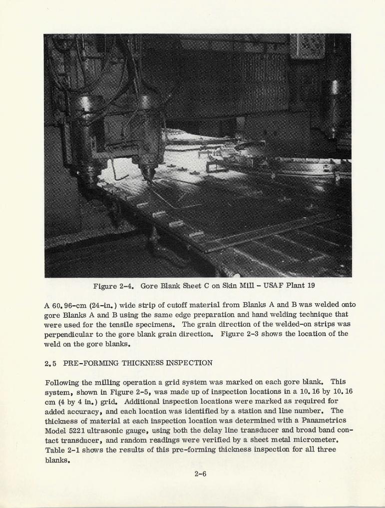
Figure 2-4. Gore Blank Sheet C on Skin Mill - USAF Plant 19
A 60. 96-cm (24-in.) wide strip of cutoff material from Blanks A and B was welded onto
gore Blanks A and B using the same edge preparation and hand welding technique that
were used for the tensile specimens. The grain direction of the welded-on strips was
perpendicular to the gore blank grain direction. Figure 2-3 shows the location of the
weld on the gore blanks.
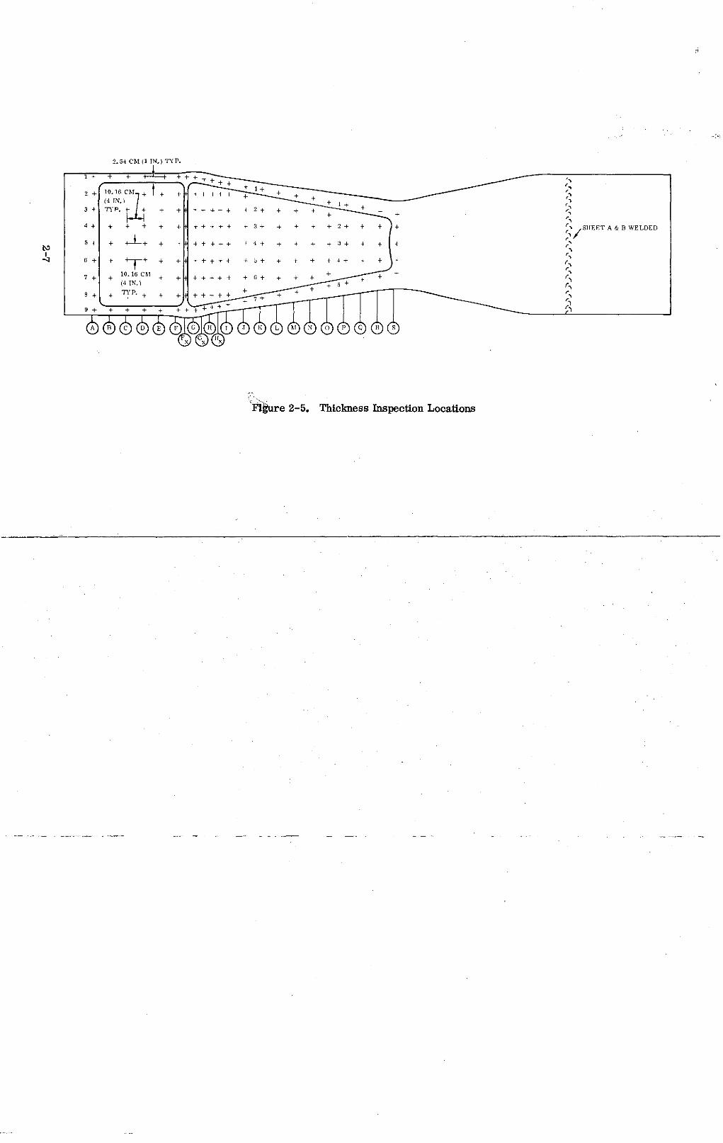
2.5 PRE-FORMING THICKNESS INSPECTION
Following the milling operation a grid system was marked on each gore blank. This
system, shown in Figure 2-5, was made up of inspection locations in a 10. 16 by 10. 16
cm (4 by 4 in.) grid. Additional inspection locations were marked as required for
added accuracy, and each location was identified by a station and line number. The
thickness of material at each inspection location was determined with a Panametrics
Model 5221 ultrasonic gauge, using both the delay line transducer and broad band con-
tact transducer, and random readings were verified by a sheet metal micrometer.
Table 2-1 shows the results of this pre-forming thickness inspection for all three
blanks.
2-6
4 6+ + + + +++++++ +5+ + + + +4+ + +
7+ 10.16 C+ + + + +(4 IN. ) + +
3 + T P ++ + ++ + + + + + ++ + +5 + + +o.+6+ 4 ++++++++ + + 4 + + + + +--3-- + + +
(4 IN.),, -- 7 -
+ + + + ++ ++ +
F G Hu J K LnNO P Q RSci L o
Flkure 2-5. Thickness Inspection Locations

Table 2-1. P e-forming Thickness Inspection, Sheets A, B, and C
StationGore
Blank Line A B C D E F Fx G Gx H Hx I J K L M N O P Q R S
mm 3.52 3.44 3.42 3.44 3.48 3.45 3.40 3.50 3.59 3.73 3.83 3.89 4.02 4.27 4.45 4.69 4.83 5.00 5.16 5.31 5.59 5.69
1 (in. (.139) (.135) (.134) (.135) (. 137) (. 136) (. 134) (. 138) (. 141) (.147) (. 151) (. 153) (. 158) (. 168) (.175) (. 184) (. 190) (. 197) (.203) (.209) (.220) (.224)
2 mm 3.55 2.46 2.46 2.48 2.49 2, 51 3.40 2.21 2.22 2.13 2.13 2.17 2.20 2.24 2.26 2.26 2.31 2.31 2.32 2.33 2.35 5.74
2 (in.) (. 140) (.097) (.097) (.097) (.098) (.099) (. 134) (. 087) (.087) (.084) (.084) (.085) (.086) (.088) (.089) (.089) (.091) (.091) (.091) (.092) (.092) (.226)
nunmm 3.51 2.41 2.48 2.46 2.51 2.50 3.43 2.27 2.21 2.12 2.15 2.11 2.17 2.26 2.26 2.30 2.30 2.35 2.29 2.29 2.32 5.69
(in.) (. 138) (.095) (.097) (.097) (.099) (. 098) (. 135) (. 089) (.087) (.083) (.084) (.083) (.085) (.089) (.089) (.090) (.090) (.092) (.090) (.090) (.091) (.224)
mm 3.44 2.45 2.48 2.49 2.51 2. 51 3.51 2.36 2.22 2.12 2.15 2.20 2.12 2.15 2.17 2.21 2.20 2.22 2.24 2.27 2.30 5.72
(in.) (. 135) (.096) (.097) (.098) (. 099) (.099) (. 138) (.093) (.087) (.083) (.084) (.086) (.083) (.084) (.085) (.087) (.086) (.087) (.088) (.089) (.090) (.225)
Blank mm 3.41 2.45 2.48 2.49 2.51 2.50 3.48 2.31 2.21 2.12 2.11 2.18 2.21 2.15 2.13 2.15 2.16 2.21 5.08 5.28 5.46 5.69
A 5 (in.) (.134) (.096) (.097) (.098) (.099) (. 098) (. 137) (.091) (.087) (.083) (.083) (.086) (.087) (.084) (.084) (.084) (. 085) (.087) (.200) (.208) (.215) (.224)
mm 3.43 2.43 2.45 2.46 2.45 2. 49 3.44 2.26 2.18 2.10 2.04 2.13 2.15 2.04 2.10 2.11 2.16 2.216(in.) (.135) (.095) (.096) (.097) (.096) (. 098) (.135) (.089) (.086) (.082) (.080) (.084) (.084) (.080) (.082) (.083) (.085) (.087)
7 mm 3.44 2.41 2.44 2.44 2.45 2.46 3.34 2.25 2. 13 2.06 2.06 2.04 2.06 4.19 4.37 4.57 4.76 4.94
(in.) (. 136) (.095) (.096) (.096) (.096) (.097) (. 131) (. 088) (.084) (.081) (.081) (.080) (.081) (. 165) (. 172) (. 180) (. 187) (.194)
8 mm 3.49 2.44 2.44 2.45 2.46 2.44 3.38 2.24 2.16 2.06 2.06 2.03 2.01
(in.) (.137) (.096) (.096) (.096) (.097) (.096) (. 133) (.088) (.085) (.081) (.081) (.080) (.079)
mm 3.51 3.45 3.29 3.31 3.31 3.31 3.24 3.35 3.45 3.58 3.62 3.68 3.87(in.) (. 138) (.136) (. 129) (.130) (. 130) (. 130) (. 127) (. 132) (. 136) (. 141) (. 142) (.145) (. 152)
Smm 3.50 3.40 3.30 3.35 3.39 3.34 3.30 3.42 3.50 3.67 3.75 3.77 4.00 4.28 4.43 4.70 4.83 4.99 5.16 5.31 5.59 5.69
(in.) (.138) (.134) (.130) (.132) (. 133) (.131) (.130) (.134) (.138) (.144) (.147) (.148) (.157) (.168) (.174) (.185) (.190) (.196) (.203) (.209) (.220) (.224)
2 mmn 3.57 2.44 2.46 2.46 2.48 2.50 3.35 2.24 2.24 2.11 2.16 2.12 2.20 2.22 2.24 2.25 2.30 2.31 2.31 2.35 2.35 5.75
S (in.) (.140) (.096) (.097) (.097) (.097) (.098) (.132) (.088) (.088) (.083) (.085) (.083) (.086) (.087) (.088) (.088) (.090) (.091) (.091) (.092) (.092) (.226)
nmm 3.48 2.41 2.45 2.44 2.48 2.48 3.43 2.25 2.20 2.08 2.12 2.07 2.18 2.25 2.26 2.29 2.30 2.33 2.29 2.31 2.33 5.75
3 (in.) (.137) (.095) (.096) (.096) (.097) (.097) (. 135) (.088) (.086) (.082) (.083) (.081) (.086) (.088) (.089) (.090) (.090) (.092) (.090) (.091) (.092) (.226)
4 mm 3.43 2.43 2.44 2.46 2.49 2,50 3.47 2.31 2.22 2.08 2.13 2.17 2.11 2.13 2.16 2.20 2.21 2.21 2.22 2.25 2.30 5.77
(in.) (. 135) (.095) (.096) (.097) (.098) (.098) (. 136) (.091) (.087) (.082) (.084) (.085) (.083) (.084) (.085) (.086) (.087) (.087) (.087) (.088) (.090) (.227)
Blank Inn 3.40 2.40 2.45 2.45 2.46 2.49 3.45 2.26 2.21 2.08 2.12 2.15 2.22 2.12 2.13 2.16 2.17 2.20 5.03 5.26 5.49 5.645iB(in.) (.134) (.094) (.096) (.096) (.097) (.098) (.136) (.089) (.087) (.082) (.083) (.084) (.087) (.083) (. 084) (.085) (.085) (.086) (. 198) (.207) (.216) (.222)
6 mm 3.35 2.37 2.43 2.44 2.45 2.44 3.43 2,25 2.18 2.06 2.07 2.11 2.12 2.03 2.06 2.08 2.16 2.16
6 (in.) (. 132) (.093) (.095) (.096) (.096) (.096), (. 135) (.088) (.086) (.081) (.081) (.083) (.083) (.080) (.081) (.082) (.085) (.085)
7 nmm 3.40 2.38 2.41 2.41 2.41 2.33 3.28 2.20 2.10 2.01 2.03 2.04 2.01 4.15 4.37 4.57 4.73 4.94
(in.) (.134) (.093) (.095) (.095) (.095) (.092) (. 129) (.086) (.082) (.079) (.080) ( 080) (.079) (. 163) (. 172) (.180) (. 186) (. 194)
8 mm 3.48 2.40 2.38 2.41 2.41 2.41 3.28 2.20 2.13 2.01 2.02 1.98 1.99(in.) (.137) (.094) (.093) (.095) (.095) (.095) (. 129) (.086) (.084) (.079) (.079) (.078) (.078)
mm 3.52 3.40 3.25 3.30 3.34 3.30 3.33 3.39 3.48 3.59 3.64 3.68 3.85(in.) (. 138) (.134) (. 128) (.130) (. 131) (. 130) (.131) (. 133) (. 137) (. 141) (. 143) (. 145) (. 151)
1 mm 3.48 3.33 3.30 3.38 3.43 3.40 3.35 3.40 3.50 3.60 3.71 3.78 4.01 4.19 4.37 4.57 4.75 4.90 5.08 5.21 5.54 5.44
(in.) (.137) (. 131) (.130) (. 133) (. 135) (. 134) (. 132) (. 134) (. 138) (. 142) (. 146) (. 149) (.158) (. 165) (.172) (. 180) (. 187) (.193) (.200) (.205) (.218) (.214)
2 mm 3.48 2.21 2.18 2.21 2.24 2.24 3.35 2.08 2.11 2.01 2.03 2.01 2.06 2.13 2.18 2.18 2.16 2.24 2.29 2.26 2.31 5.44(in.) (.137) (.087) (.086) (.087) (.088) (.088) (.132) (.082) (.083) (.079) (.080) (.079) (.081) (.084) (.086) (.086) (.085) (.088) (.090) (.089) (.091) (.214)
3 mm 3.45 2.18 2.21 2.24 2.21 2.24 3.38 2.18 2.13 2.06 2.03 2.06 2.08 2.16 2.18 2.21 2.24 2.26 2.21 2.24 2.26 5.46
(in.) (.136) (.086) (.087) (.088) (.087) (. 088) (. 133) (.086) (.084) (.081) (.080) (.081) (.082) (.085) (.086) (.087) (.088) (.089) (.087) (.088) (.089) (.215)
4 mm 3.38 2.21 2.21 2.24 2.24 2.24 3.45 2.26 2.13 2.06 2.03 2.08 2.06 2.08 2.08 2.11 2.16 2. 18 2.18 2.24 2.26 5.44
(in.) (.133) (.087) (.087) (.088) (.088) (.088) (.136) (.189) (.084) (.081) (.080) (.082) (.081) (.082) (.082) (.083) (.085) (.086) (.086) (.088) (.089) (.214)
Blank 5 mm 3.35 2.18 2.21 2.21 2.24 2.24 3.43 2.26 2.13 2.03 2.06 2.06 2.11 2.06 2.06 2.08 2.13 2.16 5.05 5.23 5.44 5.46
C (in.) (. 132) (.086) (.087) (.087) (.088) (.088) (.135) (.089) (.084) (.080) (. 081) (.081) (. 183) (.081) (.081) (.082) (.084) (. 085) (.199) (.206) (.214) (.215)
6 mm 3. 33 2.16 2.18 2.18 2.18 2.24 3.40 2.21 2.11 2.01 2.01 2.03 2.06 1.98 2.01 2.06 2.08 2.11
(in.) (. 131) (.085) (.086) (.086) (.086) (.088) (. 134) (. 187) (.083) (.079) (.079) (.080) (.081) (.078) (.079) (.081) (.082) (.083)
mm 3.38 2.16 2.16 2.16 2.16 2.16 3.40 2.18 2.08 2.01 1.98 2.01 2.01 4.11 4.32 4.52 4.70 4.88
(in.) (.133) (.085) (.085) (.085) (.085) (.085) (. 134) (.086) (.082) (.079) (.078) (.079) (.079) (. 162) (. 170) (. 178) (. 185) (. 192)
Smm 3.43 2.16 2.16 2.16 2.16 2.16 3.33 2.16 2. 11 2.01 1.96 1.93 1.91
(in.) (. 135) (.085) (.085) (.085) (.085) (. 085)' (. 131) (.085) (.083) (.079) (.077) (.076) (.075)
mm 3.45 3.38 3.30 3.28 3.28 3.28 3.20 3.25 3.38 3.53 3.60 3.71 3.91
(in.) (.136) (. 133) (. 130) (.129) (. 129) (. 128) (. 126) (. 128) (. 133) (. 139) (. 142) (. 146) (. 154)
2-JFOLDOUT FRAME FOLDOUT FRAME
2.6 TRIMMVIING OF GORE BLANKS
Average thicknesses for each station were calculated using the results of the pre-forming thickness inspection. Knowing average thicknesses, width of the pocket, andaverage weld-land width and thickness, a standard cross-sectional area was determinedfor each gore blank. The weld-land cross-sectional area for each station was variedto maintain constant cross-sectional area from Station B through R, with the exclusionof Station Fx. Table 2-2 shows average pocket and weld-land thicknesses and widthsfor each station of each gore blank. The same cross-sectional area is maintainedover the length of the gore to provide uniform elongation during the forvAing process.During the milling of Blanks A and B one edge was trimmed too close to the milledpocket to permit the desired land width of 5. 08 cm (2 in.) to be maintained. This errordecreased the cross-sectional area for these two blanks, and thus reducing the widthof the weld land.
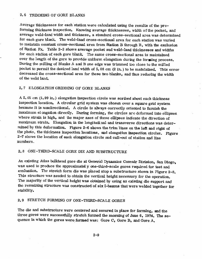
2.7 ELONGATION GRIDDING OF GORE BLANKS
A 5.05 cm (1.99 in.) elongation inspection circle was scribed about each thicknessinspection location. A circular grid system was chosen over a square grid systembecause it is nondirectional. A circle is always correctly oriented to furnish themaximum elongation directly. During forming, the circles are deformed into ellipseswhere strain is high, and the major axes of these ellipses indicate the direction ofmaximum strain. Elongation in the longitudinal and transverse directions was deter-mined by this deformation. Figure 2-6 shows the trim lines on the left and right ofthe photo, the thickness inspection locations, and elongation inspection circles. Figure2-7 shows the location of each elongation circle and call-out of station and linenumbers.
2.8 ONE-THIRD-SCALE GORE DIE AND SUBSTRUCTURE
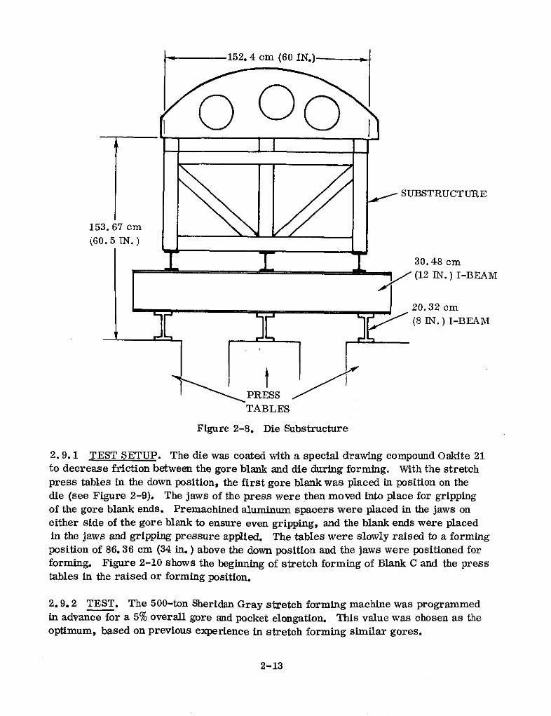
An existing Atlas bulkhead gore die at General Dynamics Convair Division, San Diego,was used to produce the approximately one-third-scale gores required for test andevaluation. The stretch.form die was placed atop a substructure shown in Figure 2-8.This structure was needed to obtain the vertical height necessary for the operation.The majority of the vertical height was obtained by using an existing die support andthe remaining structure was constructed of six I-beams that were welded together forstability.
2.9 STRETCH FORMING OF ONE-THIRD-SCALE GORES
The die and substructure were centered and secured in place for forming, and thethree gores were successfully stretch formed the morning of June 6, 1974. The se-quence in which the gores werel formed was: Gore C, Gore B, and Gore A.
2-9

(I Z' (I Z' (91 'V) (To"'0 (88"'C) W *0 0,(9"'C) (K9"U) (Be'*) (ZCg (0 QT'0) (90"*) (96"*Z) (81, Z) (60"'Z) (80o'Z) (86e'1 (66"%) (ZO'*Z) (60"*Z) (OT *Z) (OT *Z) (
690 690 L9 "01 61 '01 98 "6 8 '6 9Z 6 66 "8 61 "9 Cf"8 g0' LL L 6f "L 06 "9 1 "9 91.6 " so *9 so "9 C1 .9 18 cc 9 661' u Plml-PIOA
(VI ') (9TZ ) (90Z (661 ) (C61" (961" (6I1 () (LTI (1.0 1) (901 (8". ) " ( (09 ) (911I ( C")9 (Ei " (VI ") (66 ") (661.) -(06.) (st ") (1) ("i) 54UmPTo PruelWS Gil 69 " z 90 "0 g" 06 1, UL " 9 f0" @c" LI 1, 96 "g 9
,L 98 9 " 99 "C 9f, "c EV Be cc 's We cc *C "8 8 c " 9C OP 0C E={ -pig& at-V
0 (01'!) (00"1') (61'l9) (86 *LT) (1" 61) (S 0O0) (61 '6) (69"CZ) (CI '*9) (96 "9Z) (61 'LZ) (00°89) (U9 W8) (90 "66) 0 (0e *69) (Og *'6) (OZ6) (OZ *6g) (0g '6) 0 (u]) W1M d i0 6V6 01 "t T1 9 "I@ Zf,''"1 90'61 I'L "6 96 91 LT '09 69319 9','L9 K *69 1I L U, 'U 18 t 0 LI 'I, L T L L L13L LT 1,L 0 UWo
0 (680 ) (880 ) (890) (90 ) ( @0 (o) (660 ) (660.) (080") (080") (6LO 1 (080 1 (60'") (980 ) 0 (LO I (LO ') (LB0 ") (90 0) (90) 0 (') sau0 96"6 "z K 6 91 K "6 91 C1 *6 " I "1 60 " C 10 " O CO to * s0 " IT "6 61 'z 0 16" 1' VZ 161 8T 61 ST " 0 U= 10 ao 02--V
(90 ") (90 "9') (86 ) (96 8) (89 (1S (96 ") (9 6 ) (to 'C) (o "') ( R66) (69 "6) (L9 '3) (s0 "Z) (69 "1) (66 'I) (6 ") (08 ) (66 ) (C6) (60 *1) (60 ") ('"t)z6'0 "O "0 I "O 6SL6 99 '6 16 "8 9S *6 f6 8 08 -,1 89"L O , 6"9 LL "9 8 '* 96 *1 60 1.0 '6 669z * 6LC 89"3 89 "3 o
(oot " (816.) (00) ((061 () (81.) (6s1 (96i 1 (991') ((C1 ") (I 1(9) (91. 1) (69 1') (HE 1) (1.6 ') (GET I (I 61) (T61 1 (91") (1l ') (691.) (61.) ('Wl ) Iso m1Op PnmIL' "9 t9 "9 6"' IT "S 96 11 6 66 "6 99 1 69 " 6' " 66 1, W L "TL' " 06 C9 '" 01' "g 9": "9 cc's "C's 6g " " 6 8" 09'"6 -pt Gh.0aAV
0 (06 *V1) (1.6 '1T) (Uo'"91) (8 'LI) (9C61) (08 06) (91'66) (L '6) (1 'V6) (Z9 "W) (91W L) (40 '6) (61 '66) (1. '66) 0 (6'6Z) (L '66) (9Z6 6) (66"66) (6 '66) 0 ('"n)0 6Z "6 96 "L8 IL "I ZIP "9t LT '61, C'69 V-9 '9 "Z'09 99 "t9 99 "L9 6@ "69 ZZ "IL 96 'U1 6"L 0 LI'1"@ 99 "1L ze "IM 0631.1 0W "1, 0 Mo
0 (160.) (160 ) (680 1 (880") (60 ) (980 1 (80 ) (80 ) (680.) (60.) (680.) (I60.) (980') (80.) 0 (L0) (L60.) (960 ) (960 ) (960') 0 ('oj) 99am1al0 1t "' I "' 9z6 " 6 '6" 9T' 61 "6 91 '6 91'" I*1' s0" 80'" 90 S * K. "z 0 9'V 9 1 "z 9" W 9, " 9 WE 0 m 1 00d 02-r"Y
.cq(0 ( ))) (061') (0(',) (66'6) (SL 9) (9'6) (6'6) (99 ") (81 '6) (M. '6) (68 "') (98 "') (9 ") (16'6) (TL 'I) (6Z') (96') (1 6 (96') (66') (LO ') (40 "') ('uj)L9 "Ol L9 "01 I9'01 s0' 01 09 '6 LZ '6 98's I., solS e 86 .K ", 9L
" '"9 19 "9 z 1, 9Z'" 91 "z 1" "*' T9 U*' " U 6' Io P -
(66 .) (616) (606 ) (6 ) (961) (681) (6S ) (]L1') (L91 ) (961) (6M1.) ( ) (I0+I) (6G6.) (661I) (TV61') (ST) (1 461) (Ct ) (91') (99I (46') (CI ") es9MIoDi T Pu'Mu 96.6*9 1 66 61' 66" 06' 69, 6t f1. 6'9 96' 8L 'C U1"C 99"6 * '6 CS '6 0 el 096 Be's 09'6 9'91 96'6 69' St6 10UM -Plam a..AVV
0 (S9 'ST) (66 '1) (ot '91) (US 'L) (9C '61) (06'0) (9Z *6) (OL '66) (S1 '66) (09 '96) (96'LZ) (0 '8) (W '6) (CC '66) 0 (9'66) (f '6) (93'63) (C6 '66) (66 '66) o ('*U) qt40 @'@' L6"LC 99'U 6C"6 61S6 '6 9 ' Z 6'99 00"19 66"69 96"L9 61'69 L ' 0L 00'61 09"'fZ 0 09' *L LZ31 @8"1'L K6'9L 96311 0 Uo
0 (160 ) (060 ) (060 ) (680 ) (680.) (L ) (980 ) (80") (WO ) (80.) (60. ) (660.) (980 ') (680.) 0 (8660 .(660. (1B I ±60 ) (9601 0 (") Sea0iPIpj0 199 6 ' 697" 96 " .6 " 6 T 6" &1 "9 91 ST 1' " 1' 119 11 S '1' 96'" 0 6V'Z 61' " 91' " 91' " ' "6 0 t= 94
0Od 896aAV
S S[ b d 0 N.) N ' 31 r I XH H Xo) ) x. 3 a 0 El V
tIc[ qlPlAA pUu"I-pla"M Z-Z lqI
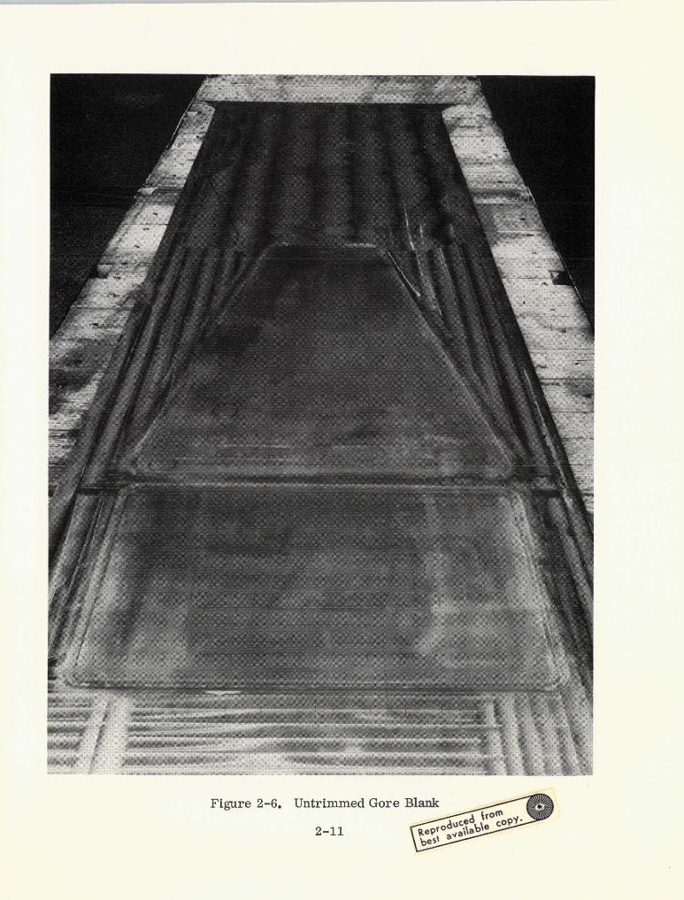
Figure 2-6. Untrimmed Gore Blank
2-11 fo 7\
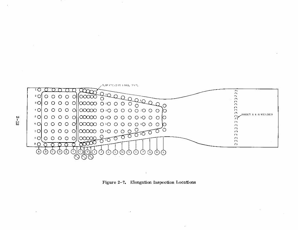
5.08 CM(2 IN.) IA. TYP.
20 00 0 00 00000
oo 0 00 0 0 0Oo - ° 2 0 0 0 .--0 040 0 0 0 0 0 00000 0:30 0 0 0 Q420 0 0
SHE A C DWELDEG
Figure 2-7. Elongation Inspection Locations
152.4 cm (60 IN.)--_
0 00
SUBSTRUCTURE
153. 67 cm
2032c
(60. 5IN. )
30.48 cm(12 IN.) I-BEAM
20. 32 cm(8 IN.) I-BEAM
PRESSTABLES
Figure 2-8. Die Substructure
2.9.1 TEST SETUP. The die was coated with a special drawing compound Oakite 21to decrease friction between the gore blank and die during forming. With the stretchpress tables in the down position, the first gore blank was placed in position on thedie (see Figure 2-9). The jaws of the press were then moved into place for grippingof the gore blank ends. Premachined aluminum spacers were placed in the jaws oneither side of the gore blank to ensure even gripping, and the blank ends were placedin the jaws and gripping pressure applied. The tables were slowly raised to a formingposition of 86.36 cm (34 in.) above the down position and the jaws were positioned forforming. Figure 2-10 shows the beginning of stretch forming of Blank C and the presstables in the raised or forming position.
2.9.2 TEST. The 500-ton Sheridan Gray stretch forming machine was programmedin advance for a 5% overall gore and pocket elongation. This value was chosen as theoptimum, based on previous experience in stretch forming similar gores.
2-13
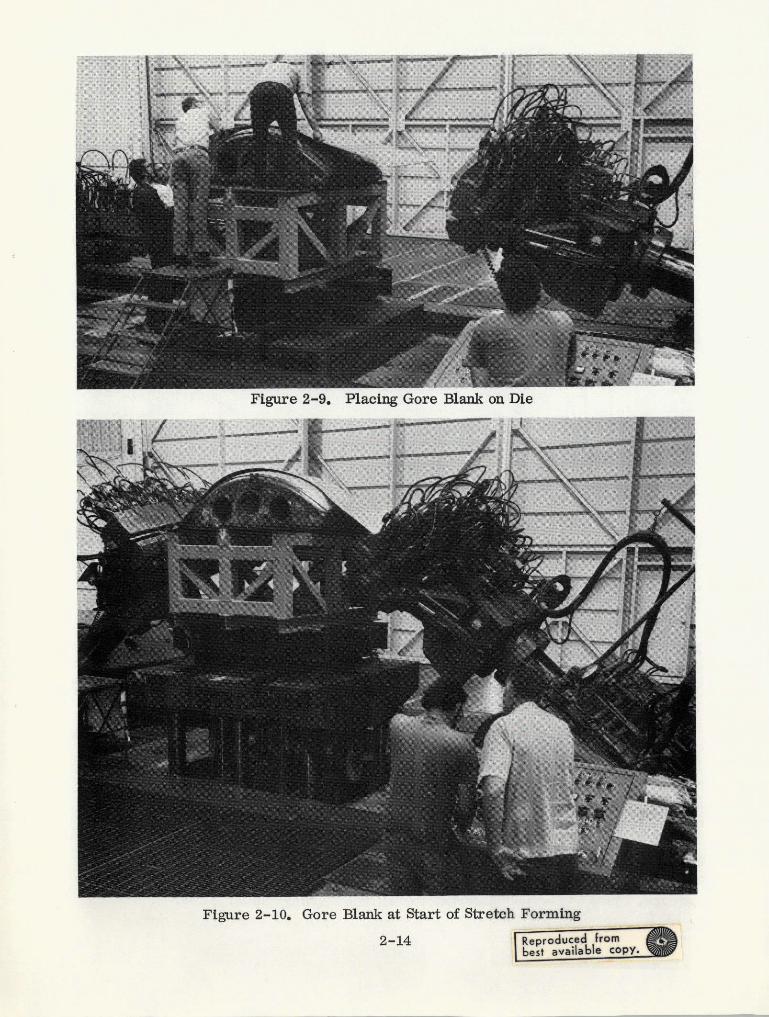
Figure 2-9. Placing Gore Blank on Die
Figure 2-10. Gore Blank at Start of Stretch Forming
2-14 Reproduc d frombest available copy.
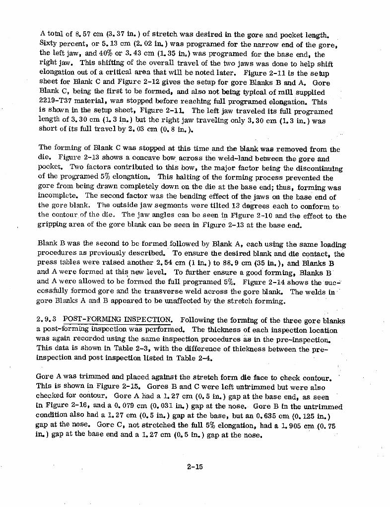
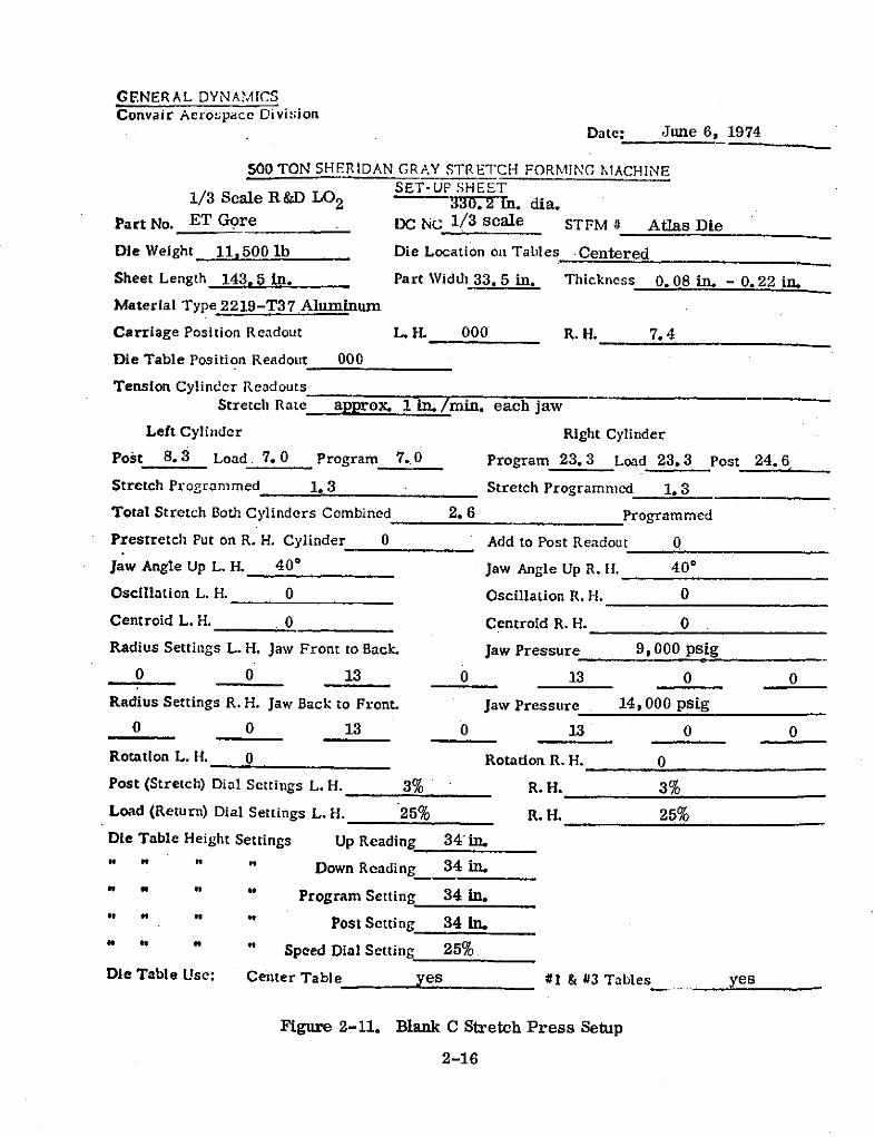
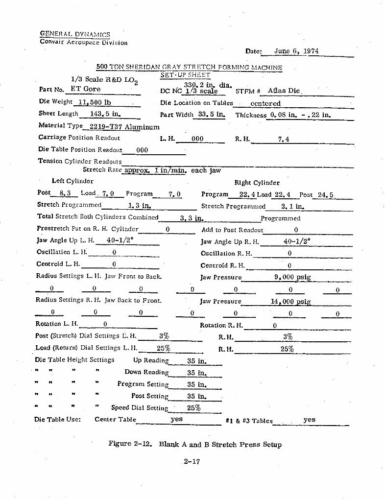
A total of 8. 57 cm (3. 37 in.) of stretch was desired in the gore and pocket length.Sixty percent, or 5.13 cm (2. 02 in.) was programed for the narrow end of the gore,the left jaw, and 40% or 3.43 cm (1. 35 in.) was programed for the base end, theright jaw. This shifting of the overall travel of the two jaws was done to help shiftelongation out of a critical area that will be noted later. Figure 2-11 is the setupsheet for Blank C and Figure 2-12 gives the setup for gore Blanks B and A. GoreBlank C, being the first to be formed, and also not being typical of mill supplied2219-T37 material, was stopped before reaching full programed elongation. Thisis showvn in the setup sheet, Figure 2-11. The left jaw traveled its full programedlength of 3.30 cm (1. 3 in.) but the right jaw traveling only 3.30 cm (1. 3 in.) wasshort of its full travel by 2. 03 cm (0. 8 in.).
The forming of Blank C was stopped at this time and the blank was removed from thedie. Figure 2-13 shows a concave bow across the weld-land between the gore andpocket. Two factors contributed to this bow, the major factor being the discontinuingof the programed 5% elongation. This halting of the forming process prevented thegore from being drawn completely down on the die at the base end; thus, forming wasincomplete. The second factor was the bending effect of the jaws on the base end ofthe gore blank. The outside jaw segments were tilted 13 degrees each to conform tothe contour of the die. The jaw angles can be seen in Figure 2-10 and the effect to thegripping area of the gore blank can be seen in Figure 2-13 at the base end.
Blank B was the second to be formed followed by Blank A, each using the same loadingprocedures as previously described. To ensure the desired blank and die contact, thepress tables were raised another 2.54 cm (1 in.) to 88.9 cm (35 in.), and Blanks Band A were formed at this new level. To further ensure a good forming, Blanks Band A were allowed to be formed the full programed 5%. Figure 2-14 shows the suc-cessfully formed gore and the transverse weld across the gore blank. The welds ingore Blanks A and B appeared to be unaffected by the stretch forming.
2.9.3 POST-FORMING INSPECTION. Following the forming of the three gore blanksa post-forming inspection was performed. The thickness of each inspection locationwas again recorded using the same inspection procedures as in the pre-inspection.This data is shown in Table 2-3, with the difference of thickness between the pre-inspection and post inspection listed in Table 2-4.
Gore A was trimmed and placed against the stretch form die face to check contour.This is shown in Figure 2-15. Gores B and C were left untrimmed but were alsochecked for contour. Gore A had a 1. 27 cm (0. 5 in.) gap at the base end, as seenin Figure 2-16, and a 0. 079 cm (0. 031 in.) gap at the nose. Gore B in the untrimmedcondition also had a 1. 27 cm (0. 5 in.) gap at the base, but an 0. 635 cm (0. 125 in.)gap at the nose. Gore C, not stretched the full 5% elongation, had a 1. 905 cm (0. 75in. ) gap at the base end and a 1. 27 cm (0. 5 in.) gap at the nose.
2-15
GENERAL DYNAMICSConvair Aero!space Division
Date: June 6, 1974
500 TON SHERIDAN GRAY STRETCH FORMING MACHINE1/3 Scale R&D L SET-UP SHEET
1/3 Scale R &D LO2 3J 2m. dia.Part No. ET Gore DC NC 1/3 scale STFM # Atlas Die
Die Weight 11,500 lb Die Location on Tables -Centered
Sheet Length 143, 5 in. Part Widdi 33.5 in. Thickness 0. 08 in. - 0. 22 in.
Material Type 2219-T37 Aluminum
Carriage Position Readout L. H. 000 R. H. 7. 4
Die Table Position Readout 000
Tension Cylinder ReadoutsStretch Rate approx. 1 in. /min. each jaw
Left Cylinder Right Cylinder
Post 8.3 Load. 7.0 Program 7.0 Program 23. 3 Load 23.3 Post 24. 6
Stretch Programmed 1.3 Stretch Programmed 1. 3
Total Stretch Both Cylinders Combined 2. 6 Programmed
Prestretch Put on R. H. Cylinder 0 Add to Post Readout 0
Jaw Angle Up L. H. 400 Jaw Angle Up R. I. 400
Oscillation L. H. 0 Oscillation R. H. 0
Centroid L. H. 0 Centroid R. H. 0
Radius Settings L. H. Jaw Front to Back. Jaw Pressure 9, 000 psig
0 0 13 0 13 0 0
Radius Settings R. H. Jaw Back to Front. Jaw Pressure 14, 000 psig
0 0 13 0 13 0 0
Rotation L. H. 0 Rotation R. H. 0
Post (Stretch) Dial Settings L. H. 3% R. H. 3%
Load (Return) Dial Settings L. H. 25% R. H. 25%
Die Table Height Settings Up Reading 34- in.
o of " Down Reading 34 in.
o of" Program Setting 34 in.
S" " Post Setting 34 in.
" Speed Dial Setting 25%
Die Table Use: Center Table yes #1 & #113 Tables yes
Figure 2-11. Blank C Stretch Press Setup
2-16
GENERAL DYNAMICSConvair Aerospace Division
Date: June 6, 1974
500 TON SHERIDAN GRAY STRETCH FORMING MACHINE
1/3 Scale R&D LO SET-UP SHEET2 330.2 in. dia.
Part No. ET Gore DC NC 1/3 scale STFM # Atlas Die
Die Weight 11,500 lb Die Location on Tables - centered
Sheet Length 143.5 in. Part Width 33. 5 in. Thickness 0. 08 in. -. 22 in.
Material Type 2219-T37 Aluminum
Carriage Position Readout L. H. 000 R. H. 7. 4
Die Table Position Readout 000
Tension Cylinder ReadoutsStretch Rate approx. 1 in/min. each jaw
Left Cylinder Right Cylinder
Post 8.3 Load. 7. 0 Program 7. 0 Program 22. 4 Load 22.4 Post 24. 5,
Stretch Programmed 1. 3 in. Stretch Programmed 2. 1 in.
Total Stretch Both Cylinders Combined 3. 3 in. Programmed
Prestretch Put on R. H. Cylinder 0 Add to Post Readout 0
Jaw Angle Up L. H. 40-1/2 Jaw Angle Up R. I. 40-1/2*
Oscillation L. H. 0 Oscillation R. H. 0
Centroid L. H. 0 Centroid R. H1. 0
Radius Settings L. H. Jaw Front to Back. Jaw Pressure 9,000 psig
0 0 0 0 0 0 0
Radius Settings R. H. Jaw Back to Front. Jaw Pressure 14,000 psig
0 0 0 0 0 0 0
Rotation L. H. 0 Rotation R. H. 0
Post (Stretch) Dial Settings t. H. 3% R.H. 3%
Load (Return) Dial Settings L. 11. 25% R.H. 25%
Die Table Height Settings Up Reading 35 in.S" " " Down Reading 35 in.
" " " " Program Setting 35 in." " " " Post Setting 35 in.
" " " " Speed Dial Setting 25%
Die Table Use: Center Table yes #1 & #3 Tables yes
Figure 2-12. Blank A and B Stretch Press Setup
2-17

Figure 2-13. Gore Blank C After Forming
Figure 2-14. Gore Blank B Showing Weld
2-18

Table 2-3. Post-forming Thickness Inspection, Sh ets A, B, and C
Gore Station
Blank Line A B C D E F Fx G Gx H Hx I J K L M N O P Q R S
1 mm 3.50 3.35 3.35 3.38 3.38 3.20 3.35 3.54 3.57 3.72 3.81 3.86 4.01 4.18 4.36 4.60 4.75 4.90 5.03 5.08 5.36 5.56(in.) (.138) (.132) (. 132) (.133) (.133) (. 126) (.132) (.139) (.140) (.146) (.150) (. 152) (.158) (. 164) (. 171) (.181) (. 187) (. 193) (.198) (.200) (.211) (.219)
2 mm 3.53 2.40 2.43 2.45 2.44 2.44 3.39 2.13 2.17 2.07 2.08 2.12 2.15 2.17 2.21 2.16 2.26 2.26 2.26 2.26 2.26 5.69(in.) (.139) (.094) (.095) (.096) (.096) (.096) (. 133) (.084) (.085) (.081) (.082) (.083) (.084) (.085) (.087) (.085) (. 089) (.089) (.089) (. 089) (. 089) (.224)
3 mm 3.50 2.36 2.43 2.43 2.46 2.48 3.43 2.21 2.11 1.98 2.07 2.01 2.08 2.21 2.17 2.20 2.25 2.29 2.21 2.20 2.22 5.66(In.) (.138) (.093) (.095) (.095) (.097) (.097) (.135) (.087) (.083) (.078) (.081) (.079) (.082) (.087) (.085) (.086) (.088) (.090) (.087) (.086) (. 087) (. 223)
4 mm 3.44 2. 41 2.41 2.45 2.49 2.50 3.50 2.30 2.12 1.97 2.03 2.08 2.02 2.08 2.10 2.15 2.08 2.16 2.18 2.21 2.22 5.69(in.) (.135) (. 095) (.095) (.096) (.098) (.098) (.138) (.090) (.083) (.077) (.080) (.082) (.079) (.082) (.082) (.084) (.082) (.085) (.086) (.087) (.087) (.224)
Blank 5 mm 3.40 2.40 2.43 2.44 2.49 2.49 3.48 2.26 2.11 1.98 2.02 2.06 2.15 2.10 2.07 2.07 2.08 2.17 5.00 5.10 5.31 5.59A 5 (in.) (.134) (.094) (.095). (.096) (.098) (.098) (.137) (.089) (.083) (.078) (.079) (.081) (.084) (.082) (.081) (.081) (.082) (.085) (. 197) (.201) (.209) (.220
6 mm 3.42 2.48 2.41 2.41 2.43 2.49 3.44 2.22 2.11 1.93 2.01 2.01 2.06 1.L99 2.04 2.06 2.11 2.13(In.) (.134) (.097) (.095) (.095) (.095) (.098) (.135) (.087) (.083) (.076) (.079) (.079) (.081) (.078) (.080) (.081) (.083) (.084)
mm 3.43 2.39 2.39 2.40 2.41 2.45 3.34 2.18 2.03 1.96 1.98 1.97 1.99 4.11 4.29 4.50 4.65 4.80(In.) (.135) (.094) (.094) (.094) (.095) (.096) (. 131) (.086) (.080) (.077) (.078) (.077) (.078) (.162) (. 169) (.177) (.183) (. 189)
8 mm 3.48 2.44 2.41 2.41 2.43 2.39 3.37 2.18 2.10 2.01 1.99 1.98 1.96(in.) (.137) (.096) (.095) (.095) (.095) (.094) (.132) (.086) (.082) (.079) (.078) (.078) (.077)mm 3.50 3.40 3.25 3.30 3.28 3.17 3.15 3.35 3.43 3.56 3.58 3.63 3.81
(in.) (.138) (.134) (.128) (.130) (.129) (.125) (.124) (.132) (.135) (.140) (.141) (.143) (.150)
1 mm 3.52 3.32 .325 3.33 3.32 3.12 3.14 3.40 3.49 3.63 3.72 3.72 3.98 4.22 4.36 4.61 4.70 4.85 5.03 5.08 5.31 5.51(in.) (.138) (.130) (.128) (.131) (.130) (.123) (.123) (. 134) (. 137) (.143) (.146) (.146) (.156) (.166) (. 171) (.181) (. 185) (.191) (.198) (.200) (.209) (.217)
2 mm 3.56 2.39 2.43 2.44 2.43 2.40 3.34 2.15 2.17 2.06 2.11 2.08 2.13 2.16 2.18 2.18 2.22 2.25 2.25 2.24 2. 24 5.66(in.) (.140) (.094) (.095) (.096) (.095) (.094) (.131) (. 084) (.085) (.081) (.083) (.082) (.084) (.085) (.086) (.086) (.087) (.088) (.088) (.088) (.088) (.223)
3 mm 3.47 2.37 2.40 2.40 2.43 2.44 3.43 2.18 2.11 1.94 2.03 1.98 2.11 2.17 2.20 2.20 2.22 2.26 2.20 2.20 2.24 5.64(in.) (.136) (.093) (.094) (.094) (.095) (.096) (.135) (.086) (.083) (.076) (.080) (.078) (. 183) (.085) (.086) (.086) (.087) (.089) (.086) (.086) (.088) (.222)
4 mm 3.43 2.37 2.39 2.41 2.45 2.49 3.48 2.26 2.13 1.90 2.01 2.07 2.01 2.07 2.08 2.13 2.13 2.15 2.13 2.16 2.21 5.64(In.) (.135) (.093) (.094) (.095) (.096) (.098) (.137) (.089) (.084) (.075) (.079) (.081) (.079) (.081) (.082) (.084) (.084) (.084) (.084) (.085) (.087) (.222)
Blank mm 3.39 2.36 2.40 2.40 2.44 2.46 3,.44 2,.21 2.12 1L90 2.01 2,.02 2,.12 2.04 2.06 2.08 2.11 2.13 4.92 5.08 5.23 5.46B 5 (In.) (. 133) (.093) (.094) (.094) (.096) (.097) (.135) (.087) (.083) (.075) (.079) (.079) (.083) (.080) (.081) (.082) (.083) (. 084) (. 193) (.200) (.206) (.215)
6 mm 3.34 2.35 2.37 2.39 2.43 2.43 3.43 2.18 2.08 1.89 1.94 1.98 2.03 1.96 1.99 2.03 2.10 2.11(In.) (.131) (.092) (.093) (.094) (.095) (.095) (.135) (.086) (.082) (.074) (.076) (.078) (.080) (.077) (.078) (.080) (.082) (.083)
mm 3.40 2.35 2.36 2.35 2.37 2.30 3.25 2.15 2.03 1.90 1.93 1.94 1.94 4.06 4.27 4.46 4.65 4.78(in.) (.134) (.092) (.093) (.092) (.093) (. 090 (.128) (.084) (.080) (.075) (.076) (.076) (.076) (.160) (.168) (.175) (.183) (.188)
mm 3.48 2.36 2.36 2.37 2.37 2.31 3.27 2.16 2.11 1.93 1.96 1.93 1.94(in.) (.137) (.093) (.093) (.093) (.093) (.091) (.128) (.085) (.083) (.076) (.077) (.076) (.076)
9 mm 3.49 3.35 3.19 3.30 3.28 3.07 3.29 3.38 3.45 3.55 3.60 3.65 3.76(In.) (.137) (.132) (.125) (.130) (.129) (.121) (.129) (.133) (.136) (.139) (.142) (.143) (.148)
1 mm 3.47 3.35 3.30 3.37 3.39 3.34 3.35 3.40 3.52 3.59 3.68 3.77 3.99 4.18 4.34 4.55 4. 72 4.90 5.07 5.18 5.38 5.41(in.) (.136) (.132) (.130) (.132) (.133) (.131) (.132) (.134) (.138) (.141) (.145) (.148) (.157) (.164) (.171) (.179) (.186) (.193) (.199) (.204) (.212) (.213)
2 mm 3.48 2.18 2.17 2.20 2.21 2.21 3.37 2.10 2.11 1.96 2.01 1.97 2.06 2.11 2.15 2.17 2.13 2.20 2.26 2.22 2.26 5.44(in.) (.137) (.086) (.085) (.086) (.087) (.087) (.132) (.082) (.083) (.077) (.079) (.077) (.081) (.083) (.084) (.085 (.084) (.086) (.089) (.087) (.089) (.214)
3 mm 3.44 2.18 2.18 2.21 2.21 2.21 3.38 2.13 2.10 1.98 1.96 1.99 2.04 2.10 2.12 2.16 2.21 2. 24 2.18 2.20 2.17 5.44(In.) (.135) (.086) (.086) (.087) (.087) (.087) (.133) (.084) (.082) (.078) (.077) (.078) (.080) (.082) (.083) (.085) (.087) (.088) (.086) (.086) (.085) (.214)
4 mm 3.38 2.20 2.20 2.21 2.22 2.22 3.45 2.21 2.07 1.96 1.96 2.01 1.99 2.02 2.03 2.07 2.12 2.16 2.16 2.20 2.22 5.41(in.) (.133) (.086) (.086) (.087) (.087) (.087) (.136) (.087) (.081) (.077) (.077) (.079) (.078) (.079) (.080) (.081) (.083) (.085) (.085) (.086) (.087) (.213)
Blank 5 mm 3.35 2.20 2.18 2.21 2.21 2.21 3.44 2.24 2.08 1.94 1.94 1.98 2.04 1.98 2.02 2.04 2.10 2.13 5.02 5.21 5.38 5.44C (in.) (.132) (.086) (.086) (.087) (.087) (.087) (.135) (.088). (.082) (.076) (.076) (.078) (.080) (.078) (.079) (.080) (.082) (.084) (.197) (.205) (.212) (.214)
6 mm 3.33 2.17 2.17 2.17 2.18 2.18 3.42 2.17 2.08 1.94 1.92 1.94 2.01 1.96 1.98 2.03 2.06 2.10(in;) (.131) (.085) (. 085) (.085) (.086) (.086) (.134) (.085) (.082) (.076) (.075) (.076) (.079) (.077) (.078) (.080) (.081) (.082)
mm 3.38 2.15 2.15 2.15 2.15 2.16 3.39 2.15 2.06 1.94 1.92 1.93 1.96 4.10 4.29 4.48 4.67 4.85(in.) (.133) (.184) (.184) (.184) (. 184) (. 185) (.133) (.084) (.081) (.076) (.075) (.076) (.077) (.161) (. 169) (.176) (.184) (.191)
mm 3.43 2.17 2.15 2.16 2.15 2.16 3.33 2.11 2.03 1.97 1.93 1.91 1. 85(in.) (.135) (.085) (.084) (.085) (.084) (.085) (.131) (.083) (.080) (.077) (.076) (.075) (.073)
9 mm 3.45 3.35 3.29 3.27 3.27 3.24 3.22 3.20 3.37 3.50 3. 59 3.68 3.87(in.) (.136) (.132) (.129) (.128) (.128) (.127) (.126) (.126) (.132) (.138) (.141) (.145) (.152)
FODUTFA2-19FOLOU FFRUT FRAME
DTaOU RA4
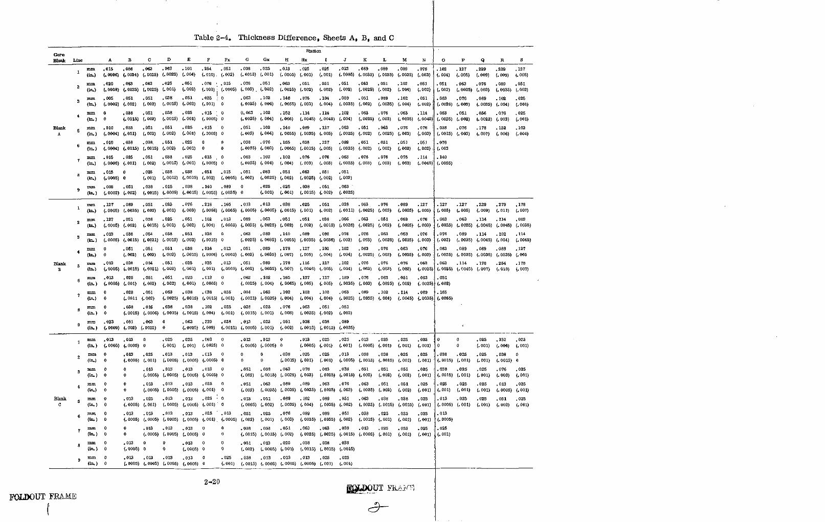
Table 2-4. Thickness Difference, Sheets A, B, and C
StationGoreBlank Line A B C D E F Fx G Gx H Hx I J K L M N O P Q R S
mm .015 .086 .063 .063 .101 .254 .051 .038 .025 .013 .025 .025 .013 .089 .089 .089 .076 .102 .127 .229 .229 .1271 (in.) (.0006) (.0034) (.0025) (.0025) (.004) (.010) (.002) (.0015) (.001) (.0005) (.001) (.001) (.0005) (.0035) (.0035) (.0035) (.003) (.004) (.005) (.009) (..009) (.005)
nmmn .020 .063 .063 .025 .051 .076 .015 .076 .051 .063 .051 .051 .051 .063 .051 .102 .051 .051 .063 .076 .089 .0512 (in.) (.0008) (.0025) (.0025) (.001) (.002) (.003) (.0005) (.003) (. 002) (.0025) (.002) (.002) (.002) (.0025) (.002) (.004) (.002) (.002) (.0025) (.003) (.0035) (.002)
mm .005 .051 .051 .038 .051 .025 0 .063 .102 .140 .076 .104 .089 .051 .089 .102 .051 .063 .076 .089 .102 .025(in.) (.0002) (.002) (.002) (.0015) (.002) (.001) 0 (.0025) (.004) (.0055) (.003) (.004) (.0035) (.002) (.0035) (.004) (.002) (.0025) (.003) (.0035) (.004) (.001)
4 mm 0 .038 .051 .038 .025 .015 0 0.063 .102 .152 .114 .114 .102 .063 .076 .063 .114 .063 .051 .056 .076 .025(in.) 0 (.0015) (.002) (.0015) (.001) (.0005) 0 (.0025) (.004) (.006) (.0045) (.0045) (.004) (.0025) (.003) (.0025) (.0045) (.0025) (.002) (.0022) (.003) (.001)
Blank mm .010 .025 .051 .051 .025 .015 0 .051 .102 .140 .089 .127 .063 .051 .063 .076 .076 .038 .076 .178 .152 .102A 5 (in.) (.0004) (.001) (.002) (.002) (.001) (.0005) 0 (.002) (.004) (. 0055) (.0035) (.005) (.0025) (.002) (. 0025) (.003) (.003) (. 0015) (.003) (.007) (.006) (.004)
mm .010 .038 .038. .051 .025 0 0 .038 .076 .165 .038 .127 .089 .051 .051 .051 .051 .0766 (in.) (.0004) (.0015) (.0015) (.002) (.001) 0 0 (.0015) (.003) (.0065) (.0015) (.005) (.0035) (.002) (.002) (.002) (.002) (.003
mm .015 .025 .051 .038 .025 .015 , 0 .063 .102 .102 .076 .076 .063 .076 .076 .076 .114 .1407 (in.) (.0006) (.001) (.002) (.0015) (.001) (.0005) 0 (.0025) (.004) (.004) (.003) (.003) (.0025) (.003) (.003) (.003) (. 0045) (.0055)
8 mm .015 0 .025 .038 .038 .051 .015 .051 .063 .051 .063 .051 .051(in.) (.0005) 0 (.001) (.0015) (.0015) (.002) (.0005) (.002) (.0025) (.002) (.0025) (.002) (.002)
mm .005 .051 .038 .015 .038 .140 .089 0 .025 .025 .038 .051 .063
(in.) (.0002) (.002) (.0015) (.0005) (.0015) (.0055) (.0035) 0 (.001) (.001) (.0015) (.002) (.0025)
nmm .127 .089 .051 .025 .076 .218 .165 .013 .013 .038 .025 .051 .028 .063 .076 .089 .127 .127 .127 .229 .279 .1781 (in.) (.0005) (.0035) (.002) (.001) (.003) (.0086) (.0065) (.0005) (.0005) (.0015) (.001) (.002) (.0011) (.0025) (.003) (.0035) (.005) (.005) (.005) (.009) (.011) (.007)
2 mm .127 .051 .038 .025 .051 .102 .013 .089 .063 .051 .051 .038 .066 .063 .051 .063 .076 .063 .063 .114 .114 .089(in.) (.0005) (.002) (.0015) (.001) (.002) (.004) (.0005) (.0035) (.0025) (.002) (.002) (.0015) (.0026) (.0025) (.002) (.0025) (.003) (.0025) (.0025) (.0045) (.0045) (.0035)
mm .013 .038 .054 .038 .051 .038 0 .063 .089 .140 .089 .092 .076 .076 .063 .063 .076 .076 .089 .114 . 102 .114
(in.) (.0005) (.0015) (.0021) (.0015) (.002) (.0015) 0 (.0025) (.0035) (.0055) (.0035) (.0036) (.003) (.003) (.0025) (.0025) (.003) (.003) (.0035) (.0045) (.004) (.0045)
mnm 0 .051 .051 .051 .038 .016 .013 .051 .089 .178 .127 .102 .102 .063 .076 .063 .076 .063 .089 .089 .089 .127(In.) 0 (.002) (.002) (.002) (.0015) (.0006) (.0005) (.002) (.0035) (.007) (.005) (.004) (.004) (.0025) (.003) (.0025) (.003) (.0025) (.0035) (.0035) (.0035) (.005
Blank 5 mm .013 .038 .054 .051 .025 .025 .013 .051 .089 .178 .116 .127 .102 .076 .076 .076 .063 .063 .114 .178 .254 .178B (in.) (.0005) (.0015) (.0021) (.002) (.001) (.001) (.0005) (.002) (.0035) (.007) (.0046) (.005) (.004) (.003) (.003) (.003) (.0025) (.0025) (.0045) (.007) (.010) (.007)
mm .013 .025 .051 .051 .025 .013 0 .063 .102 .165 .127 .127 .189 .076 .063 .051 .063 .0516 (in.) (.0005) (.001) (.002) (.002) (.001) (.0005) 0 (.0025) (.004) (.0065) (.005) (.005) (.0035) (.003) (.0025) (.002) (.0025) (.002)
mm 0 .028 .051 .063 .038 .038 .025 .054 .063 .102 .102 .102 .063 .089 .102 .114 .089 .165
(in.) 0 (.0011 (.002) (.0025) (.0015) (.0015) (.001) (.0021) (.0025) (.004) (.004) (.004) (.0025) (.0035) (.004) (.0045) (.0035) (.0065)
8 mm 0 .038 .016 .038 .038 .102 .025 .038 .025 .076 .063 .051 .0518(in.) 0 (.0015) (.0006) (.0015) (.0015) (.004) (.001) (.0015) (.001) (.003) (.0025) (.002) (.002)
mm .023 .051 .063 0 .063 .229 .038 .013 .025 .051 .038 .038 .089(in.) (.0009) (.002) (.0025) 0 (.0025) (.009) (.0015) (.0005) (.001) (.002) (.0015) (.0015) (.0035)
1 mm .013 .013 0 .025 .025 .063 0 .013 .013 0 .013 .025 .025 .013 .025 .025 .025 0 0 .025 .152 .025(in.) (.0005) (.0005) 0 (.001) (.001) (.0025) 0 (.0005) (.0005) 0 (.0005) (.001) (.001) (.0005) (.001) (.001) (.001) 0 0 (.001) (.006) (.001)
2 mm 0 .013 .025 .013 .013 .013 0 0 0 .038 .025 .025 ,.013 .038 .038 .025 .025 .038 .025 .025 .038 0(in.) 0 (.0005) (.001) (.0005) (.0005) (.0005) 0 0 0 (.0015) (.001) (.001) (.0005) (.0015) (.0015) (.001) (.001) (.0015) (.001) (.001) (.0015) 0
3 mm 0 0 .013 .013 .013 .013 0 .051 .038 .063 .076 .063 .038 .051 .051 .051 .025 .038 .025 .025 .076 .025(in.) 0 0 (.0005) (.0005) (.0005) (.0005) 0 (.002) (.0015) (.0025) (.003) (.0025) (.0015) (.002) (.002) (.002) (.001) (.0015) (.001) (.001) (.003) (.001)
4 mm 0 0 .013 .013 .013 .025 0 .051 .063 .089 .089 .063 .076 .063 .051 .051 .025 .025 .025 .025 .013 .025(in.) 0 0 (.0005) (.0005) (.0005) (.001) 0 (.002) (.0025) (.0035) (.0035) (.0025) (.003) (.0025) (.002) (.002) (.001) (.001) (.001) (.001) (.0005) (.001)
Blank 5 mm 0 .013 .025 .013 .013 .025 0 .013 .051 .089 .102 .089 .051 .063 .038 .038 .025 .013 .025 .025 .051 .025C (in.) 0 (.0005) (.001) (.0005) (.0005) (.001) 0 (.0005) (.002) (.0035) (.004) (.0035) (.002) (.0025) (.0015) (.0015) (.001) (.0005) (.001) (.001) (.002) (.001)
6 mm 0 .013 .013 .013 .013 .025 .013 .051 .025 .076 .089 .089 .051 .038 .025 .025 .025 .013(in.) 0 (.0005) (.0005) (.0005) (.0005) (.001) (.0005) (.002) (.001) (.003) (.0035) (.0035) (.002) (.0015) (.001) (.001) (.001) (.0005)
7 mm 0 0 .013 .013 .013 0 0 .038 .038 .051 .063 .063 .038 .013 .025 .025 .025 .025(in.) 0 0 (.0005) (.0005) (.0005) 0 0 (.0015) (.0015) (.002) (.0025) (.0025) (.0015) (.0005) (.001) (.001) (.001) (.001)
8 mm 0 .013 0 0 .013 0 0 .051 .013 .025 .038 .038 .038(in) 0 (.0005) 0 0 (.0005) 0 0 (.002) (.0005) (.001) (.0015) (.0015) (.0015)
mm 0 .013 .013 .013 .013 0 .025 .038 .013 .013 .013 .025 .025(in.) 0 (.0005) (.0005) (.0005) (.0005) 0 (.001) (.0015) (.0005) (.0005) (.0005) (.001) (.001)
2-20
FOLDOUT FRAME

Figure 2-15. Gore A on Die
,08
p-o~
Figure 2-16. Gore A Showing Springback
2-21
The large gap at the base end of all the formed gores was caused by a limitation
of the stretch press. This limitation is the 45-degree maximum rotation of the jaws
in the vertical plane, which prevented the part from being stretched tightly against
the die at the base end. If the jaws could have been raised to a 50- to 55-degree
angle, contact with the die could have been achieved.
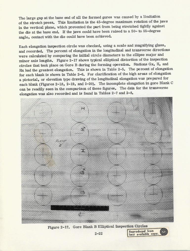
Each elongation inspection circle was checked, using a scale and magnifying glass,
and recorded. The percent of elongation in the longitudinal and transverse directions
were calculated by comparing the initial circle diameters to the ellipse major and
minor axis lengths. Figure 2-17 shows typical elliptical distortion of the inspection
circles that took place on Gore B during the forming operation. Stations Gx, H, and
Hx had the greatest elongation. This is shown in Table 2-5. The percent of elongation
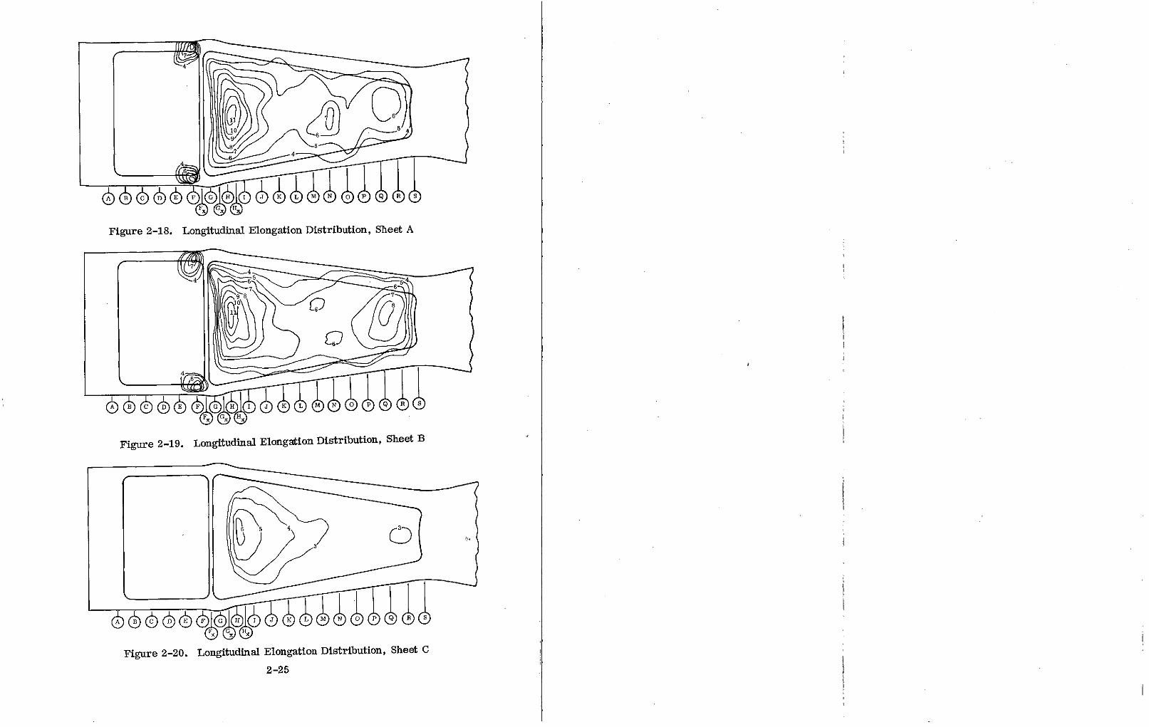
for each blank is shown in Table 2-6. For clarification of the high areas of elongation
a pictorial, or elevation type drawing of the longitudinal elongation was prepared for
each blank (Figures 2-18, 2-19, and 2-20). The incomplete elongation in gore Blank C
can be readily seen in the comparison of these figures. The data for the transverse
elongation was also recorded and is found in Tables 2-7 and 2-8.
Figure 2-17. Gore Blank B Elliptical Inspection Circles
2-22 best vailable copy.
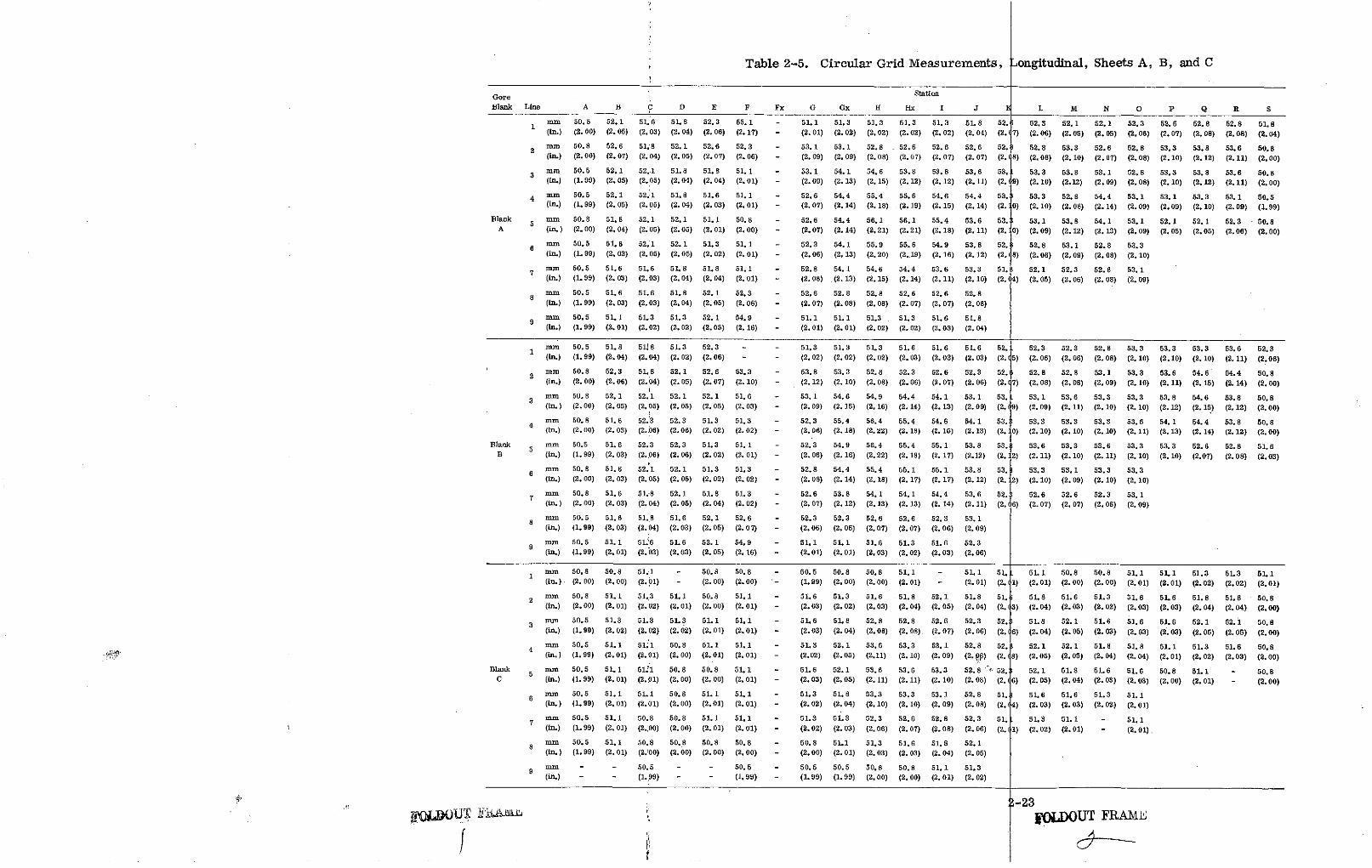
Table 2-5. Circular Grid Measurements, Longitudinal, Sheets A, B, and C
Gore Station
Blank Line A B C D E F Fx G Gx H Hix I J F L M N O P Q R S
S mm 50.8 52.1 51.6 51.8 52.3 55.1 - 51.1 51.3 51.3 51.3 51.3 51.8 52. I 52.3 52.1 52.1 52.3 52.6 52.8 52.8 51.81 (in.) (2. 00) (2.05) (2. 03) (2. 04) (2. 06) (2.17) - (2.01) (2.02) (2.02) (2.02) (2. 02) (2.04) (2. 7) (2. 06) (2. 05) (2.05) (2.06) (2.07) (2. 08) (2. 08) (2. 04)
2 mm 50.8 52.6 51.8 52.1 52.6 52.3 - 53.1 53.1 52.8 52.6 52.6 52.6 52. 1 52.8 53.3 52.6 52.8 53.3 53.8 53.6 50.8(in.) (2. 00) (2.07) (2. 04) (2. 05) (2.07) (2.06) - (2. 09) (2. 09) (2.08) (2.07) (2.07) (2.07) (2. (8) (2. 08) (2.10) (2.07) (2.08) (2.10) (2. 12) (2.11) (2.00)
3 mm 50.5 52.1 52.1 51.8 51.8 51.1 - 53.1 54.1 54.6 53.8 53.8 53.6 53. L 53.3 53.8 53.1 52.8 53.3 53.8 53.6 50.8(in.) (1. 99) (2. 05) (2.05) (2.04) (2. 04) (2.01) - (2.09) (2.13) (2.15) (2.12) (2.12) (2.11) (2. 9) (2. 10) (2.12) (2.09) (2. 08) (2.10) (2. 12) (2.11) (2. 00)
4 mm 50.5 52.1 52.1 51.8 51.6 51.1 - 52.6 54.4 55.4 55.6 54.6 54.4 53.1 53.3 52.8 54.4 53.1 53.1 53.3 53.1 50.5
(in.) (1. 99) (2.05) (2.05) (2.04) (2.03) (2.01) - (2.07) (2.14) (2.18) (2.19) (2.15) (2.14) (2. .0) (2.10) (2.08) (2.14) (2.09) (2.09) (2.10) (2.09) (1.99)
Blank 5 mm 50.8 51.8 52.1 52.1 51.1 50.8 - 52.6 54.4 56.1 56.1 55.4 53.6 53. 53.1 53.8 54.1 53.1 52.1 52.1 52.3 50.8A (in.) (2.00) (2. 04) (2.05) (2.05) (2.01) (2. 00) - (2.07) (2. 14) (2.21) (2.21) (2. 18) (2.11) (2. 0) (2.09) (2. 12) (2.13) (2.09) (2. 05) (2.05) (2. 06) (2.00)
6 mm 50.5 51.6 52.1 52.1 51.3 51.1 - 52.3 54.1 55.9 55.6 54.9 53.8 52. 52.8 53.1 52.8 53.3(in.) (1. 99) (2. 03) (2.05) (2. 05) (2.02) (2. 01) - (2. 06) (2. 13) (2.20) (2.19) (2.16) (2.12) (2. 8) (2.08) (2.09) (2.08) (2.10)
7 mm 50.5 51.6 51.6 51.8 51.8 51.1 - 52.8 54.1 54.6 54.4 53.6 53.3 51. 52.1 52.3 52.8 53.1(in.) (1.99) (2.03) (2.03) (2.04) (2.04) (2.01) - (2.08) (2.13) (2.15) (2.14) (2.11) (2.10) (2. 4) (2.05) (2.06) (2.08) (2.09)
mm 50.5 51.6 51.6 51.8 52.1 52.3 - 52.6 52.8 52.8 52.6 52.6 52.88 n(in.) (1. 99) (2.03) (2.03) (2.04) (2.05) (2.06) - (2.07) (2.08) (2.08) (2.07) (2.07) (2.08)
mm 50.5 51.1 51.3 51.3 52.1 54.9 - 51.1 51.1 51.3 - 51.3 51.6 51.8
(in.) (1.99) (2. 01) (2.02) (2. 02) (2.05) (2.16) - (2.01) (2.01) (2.02) (2.02) (2. 03) (2.04)
S mm 50.5 51.8 51.8 51.3 52.3 - - 51.3 51.3 51.3 51.6 51.6 51.6 52. 52.3 52.3 52.8 53.3 53.3 53.3 53.6 52.3(in.) (1.99) (2. 04) (2.04) (2. 02) (2.06) - - (2.02) (2.02) (2.02) (2.03) (2. 03) (2.03) (2. 5) (2.06) (2. 06) (2.08) (2. 10) (2.10) (2. 10) (2. 11) (2.06)
mm 50.8 52.3 51.8 52.1 52.6 53.3 - 53.8 53.3 52.8 52.3 52.6 52.3 52. 5 52.8 52.8 53.1 53.3 53.6 54.6 54.4 50.8
(in.) (2.00) (2.06) (2.04) (2. 05) (2. 07) (2.10) - (2.12) (2. 10) (2. 08) (2.06) (2.07) (2.06) (2. (7) (2.08) (2. 08) (2.09) (2.10) (2.11) (2.15) (2. 14) (2. 00)
3 mm 50.8 52.1 52.1 52.1 52.1 51.6 - 53.1 54.6 54.9 54.4 54.1 53.1 53. 53.1 53.6 53.3 53.3 53.8 54.6 53.8 50.8(in.) (2.00) (2.05) (2.05) (2. 05) (2. 05) (2.03) - (2.09) (2.15) (2. 16) (2.14) (2.13) (2.09) (2. (9) (2.09) (2.11) (2.10) (2.10) (2.12) (2. 15) (2. 12) (2. 00)
mm 50.8 51.6 52.3 52.3 51.3 51.3 - 52.3 55.4 56.4 55.4 54.6 54.1 53. 53.3 53.3 53.3 53.6 54.1 54.4 53.8 50.84 (in.) (2.00) (2.03) (2. 06) (2.06) (2. 02) (2.02) - (2.06) (2.18) (2.22) (2.18) (2. 15) (2.13) (2. 0) (2.10) (2. 10) (2. 10) (2.11) (2.13) (2. 14) (2. 12) (2. 00)
Blank 5 mm 50.5 51.6 52.3 52.3 51.3 51.1 - 52.3 54.9 56.4 55.4 55.1 53.8 53. 53.6 53.3 53.6 53.3 53.3 52.6 52.8 51.6B (in.) (1. 99) (2.03) (2. 06) (2. 06) (2. 02) (2.01) - (2.06) (2.16) (2.22) (2.18) (2. 17) (2.12) (2. 2) (2. 11) (2.10) (2.11) (2. 10) (2.10) (2.07) (2. 08) (2. 03)
6 mm 50.8 51.6 52.1 52.1 51.3 51.3 - 52.8 54.4 55.4 55.1 55.1 53.8 53. : 53.3 53.1 53.3 53.3(in.) (2. 00) (2.03) (2. 05) (2. 05) (2. 02) (2.02) - (2.08) (2.14) (2.18) (2.17) (2.17) (2. 12) (2. 2) (2. 10) (2.09) (2.10) (2.10)
7 mm 50.8 51.6 51.8 52.1 51.8 51.3 - 52.6 53.8 54.1 54.1 54.4 53.6 52. 52.6 52.6 52.3 53.1(in.) (2.00) (2.03) (2. 04) (2. 05) (2. 04) (2. 02) - (2.07) (2.12) (2.13) (2.13) (2.14) (2.11) (2. 6) (2.07) (2.07) (2.06) (2.09)
8 mm 50.5 51.6 51.8 51.6 52.1 52.6 - 52.3 52.3 52.6 52.6 52.3 53.1(in.) (1.99) (2. 03) (2.04) (2. 03) (2. 05) (2.0 7) - (2.06) (2.06) (2.07) (2. 07) (2.06) (2. 09)
mm 50.5 51.1 51.6 51.6 52.1 54.9 - 51.1 51.1 51.6 51.3 51.6 52.3(in.) (1. 99) (2.01) (2.03) (2.03) (2. 05) (2.16) - (2.01) (2. 01) (2.03) (2.02) (2.03) (2. 06)
1 mm 50.8 50.8 51.1 - 50.8 50.8 - 50.5 50.8 50.8 51.1 - 51.1 51. 51.1 50.8 50.8 51.1 51.1 51.3 51.3 51.1(in.) (2.00) (2, 00) (2.01) - (2. 00) (2. 00) - (1.99) (2. 00) (2.00) (2. 01) - (2.01) (2. (1) (2. 01) (2. 00) (2.00) (2. 01) (2.01) (2.02) (2.02) (2.01)
2 mm 50.8 51.1 51.3 51.1 50.8 51.1 - 51.6 51.3 51.6 51.8 52.1 51.8 51. 51.8 51.6 51.3 51.6 51.6 51.8 51.8 50.8(in.) (2. 00) (2. 01) (2.02) (2. 01) (2. 00) (2. 01) - (2.03) (2.02) (2.03) (2.04) (2.05) (2.04) (2. 3) (2. 04) (2.03) (2.02) (2.03) (2.03) (2.04) (2.04) (2. 00)
3 mm 50.5 51.3 51.3 51.3 51.1 51.1 - 51.6 51.8 52.8 52.8 52.6 52.3 52. 51.8 52.1 51.6 51.6 51.6 52.1 52.1 50.8(in.) (1.99) (2.02) (2. 02) (2. 02) (2. 01) (2. 01) - (2.03) (2.04) (2.08) (2.08). (2.07) (2.06) (2. 6) (2. 04) (2.05) (2. 03) (2.03) (2. 03) (2.05) (2. 05) (2. 00)
4 mm 50.5 51.1 51.1 50.8 51.1 51.1 - 51.3 52.1 53.6 53.3 53.1 52.8 52. 52.1 52.1 51.8 51.8 51.1 51.3 51.6 50.8(in.) (1. 99) (2.01) (2. 01) (2. 00) (2.01) (2. 01) - (2.02) (2.05) (2.11) (2.10) (2.09) (2. 06) (2. (8) (2.05) (2.05) (2.04) (2.04) (2.01) (2.02) (2.03) (2.00)
Blank 5 mm 50.5 51.1 51.1 50.8 50.8 51.1 - 51.6 52.1 53.6 53.6 53.3 52. 8 f 52. 52.1 51.8 51.6 51.6 50.8 51.1 - 50.8C (in.) (1.99) (2. 01) (2.01) (2.00) (2.00) (2. 01) - (2. 03) (2.05) (2.11) (2.11) (2.10) (2.08) (2. (6) (2. 05) (2.04) (2. 03) (2.03) (2. 00) (2. 01) - (2. 00)
6 mm 50.5 51.1 51.1 50.8 51.1 51.1 - 51.3 51.8 53.3 53.3 53.1 52.8 51. 51.6 51.6 51.3 51.16 (in.) (1.99) (2.01) (2.01) (2. 00) (2.01) (2. 01) - (2. 02) (2.04) (2. 10) (2. 10) (2.09) (2.08) (2. 14) (2.03) (2. 03) (2.02) (2. 01)
mm 50.5 51.1 50.8 50.8 51.1 51.1 - 51.3 51.3 52.3 52.6 52.8 52.3 51. 51.3 51.1 - 51.1(in.) (1.99) (2. 01) (2.00) (2. 00) (2. 01) (2. 01) - (2.02) (2.03) (2.06) (2.07) (2.08) (2.06) (2. 1 1) (2.02) (2. 01) - (2.01)
nmm 50.5 51.1 50.8 50.8 50.8 50.8 - 50.8 51.1 51.3 51.6 51.8 52.1
(in.) (1.99) (2.01) (2.00) (2. 00) (2.00) (2. 00) - (2. 00) (2. 01) (2.03) (2.03) (2.04) (2.05)
mm - - 50.5 - - 50.5 - 50.5 50.5 50.8 50.8 51.1 51.3(in.) - - (1.99) - - (1.99) - (1.99) (1.99) (2.00) (2.00) (2.01) (2.02)
S-23J()D O i-E IL IODOUT FRAME
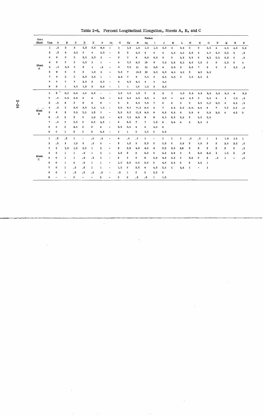
Table 2-6. Percent Longitudinal Elongation, Sheets A, B, and C
Gore Station
Blank Line A B C D E F Fx G Gx H Hx I J K L M N O P Q R S
1 .5 3 2 2.5 3.5 9.5 - 1 1.5 1.5 1.5 1.5 2.5 4 3.5 3 3 3.5 4 4.5 4.5 2.5
2 .5 4 2.5 3 4 3.5 - 5 5 4.5 4 4 4 4.5 4.5 5.5 4 4.5 5.5 6.5 6 .5
3 0 3 3 2.5 2.5 1 - 5 7 8 6.5 6.5 6 5 5.5 6.5 5 4.5 5.5 6.5 6 .5
4 0 3 3 2.5 2 1 - 4 7.5 9.5 10 8 7.5 5.5 5.5 4.5 7.5 5 5 5.5 5 0Blank
A 5 .5 2.5 3 3 1 .5 - 4 7.5 11 11 9.5 6 5.5 5 6.5 7 5 3 3 3.5 .5A
6 0 2 3 3 1.5 1 - 3.5 7 10.5 10 8.5 6.5 4.5 4.5 5 4.5 5.5
7 0 2 2 2.5 2.5 1 - 4.5 7 8 7.5 6 5.5 2.5 3 3.5 4.5 5
8 0 2 2 2.5 3 3.5 - 4 4.5 4.5 4 4 4.5
9 0 1 1.5 1.5 3 8.5 - 1 1 1.5 1.5 2 2.5
1 0 2.5 2.5 1.5 3.5 - - 1.5 1.5 1.5 2 2 2 3 3.5 3.5 4.5 5.5 5.5 5.5 6 3.5
2 .5 3.5 2.5 3 4 5.5 - 6.5 5.5 4.5 3.5 4 3.5 4 4.5 4.5 5 5.5 6 8 7.5 .5
I 3 .5 3 3 3 3 2 - 5 8 8.5 7.5 7 5 5 5 6 5.5 5.5 6.5 8 6.5 .5
- 4 .5 2 3.5 3.5 1.5 1.5 - 3. 5 9.5 11.5 9.5 8 7 5.5 5.5 -5.5- 5.5 6 7 7.5 6.5 .5Blank
B 5 0 2 3.5 3.5 1.5 1 - 3.5 8.5 11.5 9.5 9 6.5 6.5 6 5.5 6 5.5 5.5 4 4.5 2B
6 .5 2 3 3 1.5 1.5 - 4.5 7.5 9.5 9 9 6.5 6.5 5.5 5 5.5 5.5
7 .5 2 2.5 3 2.5 1.5 - 4 6.5 7 7 7.5 6 . 3.5 4 4 3.5 5
8 0 2 2.5 2 3 4 - 3.5 3.5 4 4 3.5 5
9 0 1 2 2 3 8.5 - 1 1 2 1.5 2 3.5
1 .5 .5 1 - .5 .5 - 0 .5 .5 1 - 1 1 1 .5 .5 1 1 1.5 1.5 1
2 .5 1 1.5 1 .5 1 - 2 1.5 2 2.5 3 2.5 2 2.5 2 1.5 2 2 2.5 2.5 .5
3 0 1.5 1.5 1.5 1 1 - 2 2.5 4.5 4.5 4 3.5 3.5 2.5 3 2 2 2 3 3 .5
4 0 1 1 .5 1 1 - 1.5 3 6 5.5 5 4.5 4.5 3 3 2.5 2.5 1 1.5 2 .5BlankBlank 5 0 1 1 .5 .5 1 - 2 3 6 6 5.5 4.5 3.5 3 2.5 2 2 .5 1 - .5
C6 0 1 1 .5 1 1 - 1.5 2.5 5.5 5.5 5 4.5 2.5 2 2 1.5 1
7 0 1 .5 .5 1 1 - 1.5 2 3.5 4 4.5 3.5 1 1.5 1 - 1
8 0 1 .5 .5 .5 .5 - .5 1 2 2 2.5 3
9 - - 0 - - 0 - 0 0 .5 .5 1 1.5
44
8 5
Figure 2-18. Longitudinal Elongation Distribution, Sheet A
4
Figure 2-19. Longitudinal Elongation Distribution, Sheet B
7
Figure 2-20. Longitudinal Elongation Distribution, Sheet C
2-25
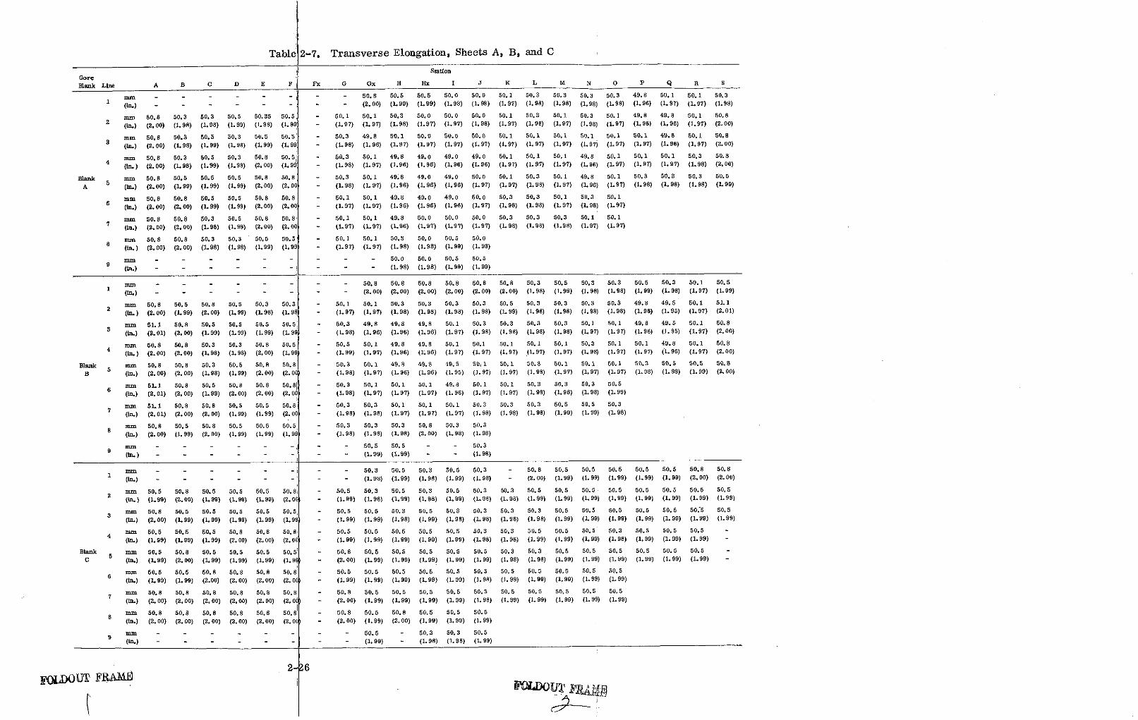
Table 2-7. Transverse Elongation, Sheets A, B, and C
StationGore
Blank Line A B C D E F Fx G Gx H Hx I J K L M N O P Q R S
nmmn - - - - - - - - 50.8 50.5 50.5 50.0 50.0 50.1 50.3 50.3 50.3 50.3 49.8 50.1 50.1 50.3
1 (in.) - - - - - - - - (2.00) (1.99) (1.99) (1.98) (1.98) (1.97) (1.98) (1.98) (1.98) (1.98) (1.96) (1.97) (1.97) (1.98)
mm 50.8 50.3 50.3 50.5 50.35 50.5 - 50.1 50.1 50.3 50.0 50.0 50.0 50.1 50.3 50.1 50.3 50.1 49.8 49.8 50.1 50.8
2 (in.) (2.00) (1.98) (1.98) (1.99) (1.98) (1.99 - (1.97) (1.97) (1.98) (1.97) (1.97) (1.98) (1.97) (1.98) (1.97) (1.98) (1.97) (1.96) (1.96) (1.97) (2.00)
mm 50.8 50.3 50.5 50.3 50.5 50.5 - 50.3 49.8 50.1 50.0 50.0 50.0 50.1 50.1 50.1 50.1 50.1 50.1 49.8 50.1 50.8
3 (in.) (2. 00) (1.98) (1.99) (1.98) (1.99) (1.99 - (1.98) (1.96) (1.97) (1.97) (1.97) (1.97) (1.97) (1.97) (1.97) (1.97) (1.97) (1.97) (1.96) (1.97) (2.00)
mm 50.8 50.3 50.5 50.3 50.8 50.5! - 50.3 50.1 49.8 49.0 49.0 49.0 50.1 50.1 50.1 49.8 50.1 50.1 50.1 50.3 50.8
4 (in.) (2.00) (1.98) (1.99) (1.98) (2.00) (1.99 - (1.98) (1.97) (1.96) (1.96) (1.96) (1.96) (1.97) (1.97) (1.97) (1.96) (1.97) (1.97) (1.97) (1.98) (2.00)
Blank mm 50.8 50.5 50.5 50.5 50.8 50.8 - 50.3 50.1 49.8 49.0 49.0 50.0 50.1 50.3 50.1 49.8 50.1 50.3 50.3 50.3 50.5
A 5 (in.) (2.00) (1.99) (1.99) (1.99) (2.00) (2.00 - (1.98) (1.97) (1.96) (1.96) (1.96) (1.97) (1.97) (1.98) (1.97) (1.96) (1.97) (1.98) (1.98) (1.98) (1.99)
6 mm 50.8 50.8 50.5 50.5 50.8 50.8 - 50.1 50.1 49.8 49.0 49.0 50.0 50.3 50.3 50.1 50.3 50.1
6 (in.) (2. 00) (2. 00) (1.99) (1. 99) (2.00) (2. 00 - (1.97) (1.97) (1.96) (1. 96) (1. 96) (1. 97) (1. 98) (1. 98) (1.97) (1. 98) (1.97)
mm 50.8 50.8 50.3 50.5 50.8 50.8 - 50.1 50.1 49.8 50.0 50.0 50.0 50.3 50.3 50.3 50.1 50.17 (in.) (2.00) (2.00) (1.98) (1.99) (2.00) (2.00 - (1.97) (1.97) (1.96) (1.97) (1.97) (1.97) (1.98) (1.98) (1.98) (1.97) (1.97)
8 mm 50.8 50.8 50.3 50.3 50.5 50.5 - 50.1 50.1 50.3 50.0 50.5 50.0
(in.) (2.00) (2.00) (1.98) (1.98) (1.99) (1.99 - (1.97) (1.97) (1.98) (1.98) (1.99) (1.98)
mm - - - - - - - - - 50.0 50.0 50.5 50.5
(in.) - - - - - - - - - (1.98) (1.98) (1.99) (1.99)
1 mm - - - - - - - - 50.8 50.8 50.8 50.8 50.8 50.8 50.3 50.5 50.3 50.3 50.5 50.3 50.1 50.5
1 (in.) - - - - - - - - (2.00) (2.00) (2. 00) (2.00) (2. 00) (2.00) (1. 98) (1.99) (1. 98) (1. 98) (1. 99) (1. 98) (1. 97) (1. 99)
2 mm 50.8 50.5 50.8 50.5 50.3 50.3 - 50.1 50.1 50.3 50.3 50.3 50.3 50.5 50.3 50.3 50.3 50.3 49.8 49.5 50.1 51.1
2 (in.) (2.00) (1.99) (2.00) (1.99) (1.98) (1.98 - (1.97) (1.97) (1.98) (1.98) (1.98) (1.98) (1.99) (1.98) (1.98) (1.98) (1.98) (1.96) (1.95) (1.97) (2.01)
mm 51.1 50.8 50.5 50.5 50.5 50.5 - 50.3 49.8 49.8 49.8 50.1 50.3 50.3 50.3 50.3 50.1 50.1 49.8 49.5 50.1 50.8
3 (in.) (2.01) (2.00) (1.99) (1.99) (1.99) (1.99 - (1.98) (1.96) (1.96) (1.96) (1.97) (1.98) (1.98) (1.98) (1.98) (1.97) (1.97) (1.96) (1.95) (1.97) (2.00)
mm 50.8 50.8 50.3 50.3 50.8 50.5 - 50.5 50.1 49.8 49.8 50.1 50.1 50.1 50.1 50.1 50.3 50.1 50.1 49.8 50.1 50.8
4 (in.) (2.00) (2.00) (1.98) (1.98) (2.00) (1.99 - (1.99) (1.97) (1.96) (1.96) (1.97) (1.97) (1.97) (1.97) (1.97) (1.98) (1.97) (1.97) (1.96) (1.97) (2.00)
Blank mm 50.8 50.8 50.3 50.5 50.8 50.8 - 50.3 50.1 49.8 49.8 49.5 50,1 50.1 50.3 50.1 50.1 50.1 50.3 50.5 50.5 50.8
B 5 (in.) (2.00) (2.00) (1.98) (1.99) (2.00) (2.00 - (1.98) (1.97) (1.96) (1.96) (1.95) (1.97) (1.97) (1.98) (1.97) (1.97) (1.97) (1.98) (1. 99) (1.99) (2.00)
6 mm 51.1 50.8 50.5 50.8 50.8 50.81 - 50.3 50.1 50.1 50.1 49.8 50.1 50.1 50.3 50.3 50.3 50.5
6 (in.) (2.01) (2.00) (1.99) (2. 00) (2.00) (2.00 (1.98) (1.97) (1.97) (1.97) (1.96) (1.97) (1.97) (1.98) (1.98) (1.98) (1.99)
mm 51.1 50.8 50.8 50.5 50.5 50.8 - 50.3 50.3 50.1 50.1 50.1 50.3 50.3 50.3 50.5 50.5 50.3
(in.) (2.01) (2.00) (2.00) (1.99) (1.99) (2.00 - (1.98) (1.98) (1.97) (1.97) (1.97) (1.98) (1.98) (1.98) (1.99) (1.99) (1.98)
8 mm 50.8 50.5 50.8 50.5 50.5 50.5 - 50.3 50.3 50.3 50.8 50.3 50.3
8 (In.) (2.00) (1.99) (2.00) (1.99) (1.99) (1.99 - (1.98) (1.98) (1.98) (2.00) (1.98) (1.98)
mm - - - - - - - - 50.5 50.5 - - 50.3
9 (in.) - - - - - - - - (1.99) (1.99) - - (1.98)
mm - - - - - - - 50.3 50.5 50.3 50.5 50.3 - 50.8 50.5 50.5 50.5 50.5 50.5 50.8 50.8
1 (in.) - - - - - - - - (1.98) (1.99) (1.98) (1.99) (1.98) - (2.00) (1.99) (1.99) (1.99) (1.99) (1.99) (2.00) (2.00)
2 mm 50.5 50.8 50.5 50.5 50.5 50.8 - 50.5 50.3 50.5 50.3 50.5 50.3 50.3 50.5 50.5 50.5 50.5 50.5 50.5 50.5 50.5
2 (in.) (1.99) (2.00) (1.99) (1.99) (1.99) (2.00 - (1.99) (1.98) (1.99) (1.98) (1.99) (1.98) (1.98) (1.99) (1.99) (1.99) (1.99) (1.99) (1.99) (1.99) (1.99)
mm 50.8 50.5 50.5 50.5 50.5 50.5 - 50.5 50.5 50.3 50.5 50.3 50.3 50.3 50.3 50.5 50.5 50.5 50.5 50.5 50:5 50.5
3 (in.) (2.00) (1.99) (1.99) (1.99) (1.99) (1.99 - (1.99) (1.99) (1.98) (1.99) (1.98) (1.98) (1.98) (1.98) (1.99) (1.99) (1.99) (1.99) (1.99) (1.99) (1.99)
mm 50.5 50.5 50.5 50.8 50.8 50.8 - 50.5 50.5 50.5 50.5 50.5 50.3 50.3 50.5 50.5 50.5 50.3 50.5 50.5 50.5 -
4 (In.) (1.99) (1.99) (1.99) (2.00) (2.00) (2. 00 - (1.99) (1.99) (1.99) (1.99) (1.99) (1.98) (1.98) (1.99) (1.99) (1.99) (1.98) (1.99) (1.99) (1.99) -
Blank mm 50.5 50.8 50.5 50.5 50.5 50.5 - 50.8 50.5 50.5 50.5 50.5 50.5 50.3 50.3 50.5 50.5 50.5 50.5 50.5 50.5 -
C 5 (in.) (1.99) (2.00) (1.99) (1.99) (1.99) (1. 99 - (2.00) (1.99) (1.99) (1.99) (1.99) (1.99) (1.98) (1.98) (1.99) (1.99) (1.99) (1.99) (1.99) (1.99) -
mm 50.5 50.5 50.8 50.8 50.8 50.8 - 50.5 50.5 50.5 50.5 50.5 50.3 50.5 50.5 50.5 50.5 50.56 (in.) (1.99) (1.99) (2.00) (2.00) (2.00) (2.0( - (1.99) (1.99) (1.99) (1.99) (1.99) (1.98) (1.99) (1.99) (1.99) (1.99) (1.99)
mm 50.8 50.8 50.8 50.8 50.8 50.8 - 50.8 50.5 50.5 50.5 50.5 50.3 50.5 50.5 50.5 50.5 50.5
(in.) (2. 00) (2.00) (2. 00) (2.00) (2. 00) (2. 0 - (2.00) (1.99) (1.99) (1.99) (1. 99) (1.98) (1.99) (1. 99) (1.99) (1.99) (1.99)
mm 50.8 50.8 50.8 50.8 50.8 50. 8 - 50.8 50.5 50.8 50.5 50.5 50.5
8 (in.) (2.00) (2.00) (2. 00) (2. 00) (2. 00) (2. 00O - (2.00) (1.99) (2.00) (1.99) (1.99) (1.99)
mm - - - - - - - - 50.5 - 50.3 50.3 50.5
(in.) - - - - - - - - (1.99) - (1.98) (1.98) (1.99)
2-26FOLUOUT FAVF
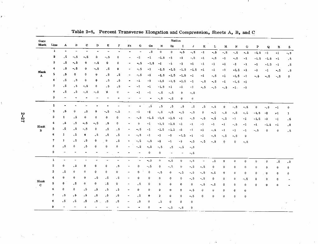
Table 2-8. Percent Transverse Elongation and Compression, Sheets A, B, and C
Gore StationBlank Line A B C D E F Fx G Gx H Hx I J K L M N O P Q R S
1 - - - - - - - .5 0 0 -. 5 -. 5 -1 -. 5 -. 5 -. 5 -. 5 -1.5 -1 -1 -. 52 .5 -. 5 -. 5 0 -. 5 0 - -1 -1 -1.5 -1 -1 -. 5 -1 -. 5 -1 -. 5 -1 -1.5 -1.5 -1 .53 .5 -. 5 0 -. 5 0 0 - -. 5 -1.5 -1 -1 -1 -1 -1 -1 -1 -1 -1 -1 -1.5 -1 .54 .5 -. 5 0 -. 5 .5 0 - -. 5 -1 -1.5 -1.5 -1.5 -1.5 -1 -1 -1 -1.5 -1 -1 -1 -. 5 .5
A 5 .5 0 0 0 .5 .5 - -. 5 -1 -1.5 -1.5 -1.5 -1 -1 -. 5 -1 -1.5 -1 -. 5 -. 5 -. 5 06 .5 .5 0 0 .5 .5 - -1 -1 -1.5 -L5 -1.5 -1 -. 5 -. 5 -1 -1.5 -1
7 .5 .5 -. 5 0 .5 .5 - -1 -1 -1.5 -1 -1 -1 -. 5 -. 5 -. 5 -1 -18 .5 .5 -. 5 -. 5 0 0 - -1 -1 -. 5 -. 5 0 -. 5
9 - - - - - - - - - .5 -. 5 0 0
1 - - - - - - - - .5 .5 .5 .5 .5 .5 -. 5 0 -. 5 -. 5 0 -. 5 -1 02 .5 0 .5 0 -. 5 -. 5 - -1 -1 -. 5 -. 5 -. 5 -. 5 0 -. 5 -. 5 -. 5 -. 5 -1.5 -2 .-1 13 1 .5 0 0 0 0 - -. 5 -1.5 -1.5 -1.5 -1 -. 5 -. 5 -. 5 -. 5 -1 -1 -1.5 -2 -1 .54 .5 .5 -. 5 -. 5 .5 0 - 0 -1 -1.5 -1.5 -1 -1 -1 -1 -1 -. 5 -1 -1 -1.5 -1 .5
Blank .B 5 .5 .5 -. 5 0 .5 .5 - -. 5 -1 -1.5 -1.5 -2 -1 -1 -. 5 -1 -1 -1 -. 5 0 0 .5
6 1 .5 0 .5 .5 .5 - -. 5 -1 -1 -1 -1.5 -1 -1 -. 5 -. 5 -. 5 0
7 1 .5 .5 0 0 .5 - -. 5 -. 5 -1 -1 -1 -. 5 -. 5 -. 5 0 0 -. 5
8 .5 0 .5 0 0 0 - -. 5 -. 5 -. 5 .5 -. 5 -. 5
9 - - - - - - - - 0 0 - -. 5
1 - - - - - - - - .5 0 -. 5 0 -. 5 - .5 0 0 0 0 0 .5 .52 0 .5 0 0 0 .5 0 -. 5 0 -. 5 0 -. 5 -. 5 0 0 0 0 0 0 0 03 .5 0 0 0 0 0 - 0 0 -. 5 0 -. 5 -. 5 -. 5 -. 5 0 0 0 0 0 0 04 0 0 0 .5 .5 .5 - 0 0 0 0 0 -. 5 -. 5 0 0 0 -. 5 0 0 0
Blank 0 .5 0 0 .5 0 .5 0 0 0 0 0 -. 5 -. 5 0 0 0 0 0 0
6 0 0 .5 .5 .5 .5 - 0 0 0 0 0 -. 5 0 0 0 0 0
7 .5 .5 .5 .5 .5 .5 - .5 0 0 0 0 -. 5 0 0 0 0 0
8 .5 .5 .5 .5 .5 .5 - .5 0 .5 0 0 0
9 - - - - - - - 0 -. 5 -. 5 0
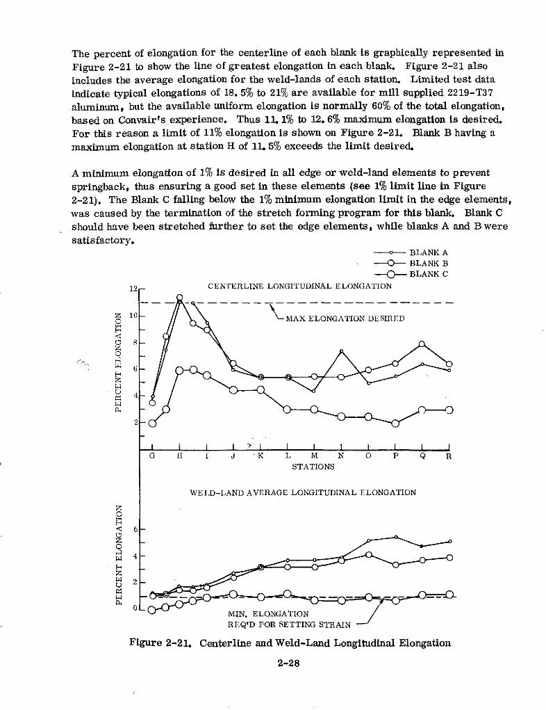
The percent of elongation for the centerline of each blank is graphically represented in
Figure 2-21 to show the line of greatest elongation in each blank. Figure 2-21 also
includes the average elongation for the weld-lands of each station. Limited test dataindicate typical elongations of 18. 5% to 21% are available for mill supplied 2219-T37aluminum, but the available uniform elongation is normally 60% of the total elongation,based on Convair's experience. Thus 11. 1% to 12.6% maximum elongation is desired.For this reason a limit of 11% elongation is shown on Figure 2-21. Blank B having amaximum elongation at station H of 11. 5% exceeds the limit desired.
A minimum elongation of 1% is desired in all edge or weld-land elements to prevent
springback, thus ensuring a good set in these elements (see 1% limit line in Figure2-21). The Blank C falling below the 1% minimum elongation limit in the edge elements,was caused by the termination of the stretch forming program for this blank. Blank Cshould have been stretched further to set the edge elements, while blanks A and B weresatisfactory.
SBLANK A
BLANK B
--- BLANK C
12 CENTERLINE LONGITUDINAL ELONGATION
z 10- -MAX ELONGATION DESIRED
0 8z
z
4
2
I i I I " I I I I I I I IG H I J K L M N 0 P Q R
STATIONS
WELD-LAND AVERAGE LONGITUDINAL ELONGATION
O
O 6
S4
z
2-
0MIN. ELONGATIONREQ'D FOR SETTING STRAIN -
Figure 2-21. Centerline and Weld-Land Longitudinal Elongation
2-28
2.10 PACKAGING AND SHIPPING
The three gores plus all cutoff material from the gore blanks were packaged in a singlewooden box for shipment by truck to NASA/MSFC, Alabama. The box was custommade with two contour-matching vertical supports proportionally located on the boxbase to support the full width of the compound contoured gores. The gores were in-stalled in the box with the concave sides down. The ends of the gores were fittedagainst blocks on the box to prevent shifting. The parts were separated with cushion-ing material for protection, and secured to the base by steel strapping over the verti-cal support locations. Parent material that was trimmed off of the edges of each blankbefore forming was strapped to the base under the parts. Each piece of this trim ma-terial and each gore was identified with its corresponding blank number for identifica-tion by both impression stamping and marking pen. The approximate dimensions ofthe wooden shipping box were 99. 06 cm (39 in.) high by 96. 52 cm (38 in.) wide by365. 76 cm (144 in.) long. The box was shipped to MSFC via Leeway Freight Lineson 11 June 1974.
2.11 CONCLUSIONS
The conclusions reached are as follows:
1. The successful room temperature STFM of the three 2219-T37 one-third-scalegores show that the gores of a 12-gore configuration blukhead can be fabricatedusing this process.
2. If the stretch press jaws could have been rotated to a greater vertical angle, itis believed that the gores would have been formed completely to the die at the baseend without difficulty, and the amount of stretch could possibly be reduced.
3. It may be possible to stretch form gores to an 11- or 10-gore bulkhead configura-tion if the amount of stretch can be reduced; however, available uniform materialelongation is the governing factor. An 11- or 10-gore bulkhead configuration couldresult in a much higher scrap rate (> 5%).
2-29
SECTION 3
PHASE II - PRODUCTION DIE DESIGN, TOOLING COSTSTUDY, AND PRODUCTION COST STUDY
3.1 GENERAL INFORMATION
The designs and costs in Phase II were to be compiled, if possible, for all of thefollowing configurations:
1. Production of LH2 Tank Dome gores per MMC Dwg. 82600202000 (200 in. cap,12 gores).
2. Production of LH 2 Tank Dome gores per MMC Dwg. 82600202001 (140 in. cap,12 gores).
3. Production of LO2 Tank Dome gores, no MMC Dwg. available (200 in. cap,8 gores).
4. Production of LO2 Tank Dome gores per MMC Dwg. 82600203500 (140 in. cap,8 gores).
5. Production of 12 gores for MMC LH2 Dome Configuration (one-half an ellipsoidwith major and minor axes of 165. 1 and 123. 825 in. respectively) but with theoptimum size of cap based on GD/C studies.
6. Production of 8 gores for the MMIC LO2 Dome Configuration (one-half an ellipsoidwith major and minor axes of 165. 1 and 123.825 in. respectively) but with opti-mum size cap based on GD/C studies.
7. Production of 12 gores for the MMC LO2 Dome Configuration (one-half an ellip-soid with major and minor axes of 165. 1 and 123. 825 in. respectively) but withoptimum size cap based on GD/C studies.
8. Production of the least number of gores for the MMC LH2 Tank Dome with the 200in. diameter cap that can be made with existing stretch presses in the country andthe material sizes available. See MMC Dwg. 82600202000.
9. Production of the least number of gores for the MMC LH2 Tank Dome with the 140in. diameter cap that can be made with existing stretch presses in the Countryand the material sizes available. See MMC Dwg. 82600202001.
10. Production of the least number of gores for the MMC LO2 Tank Dome with the 200in. diameter cap that can be made with existing stretch presses in the Countryand the material sizes available. See MMC Dwg. 82600203500.
11. Production of the least number of gores for the MMC LO2 Tank Dome with the 140in. diameter cap that can be made with existing stretch presses in the Country andthe material sizes available. See MMC Dwg. 82600203500.
3-1
12. Production of the least number of gores for the MMC LH2 Dome configuration and
the optimum size cap based on GD/C studies.
13. Production of the least number of gores for the MMC LO2 Dome configuration and
the optimum size cap based on GD/C studies.
This list of 13 configurations was reduced to seven configurations because: a) previous
experience showed that the minimum number of gores per bulkhead that can be formed
is 10, and, b) duplication of configurations occurred after establishing the least number
of gores for the desired polar cap diameters. The seven configurations and their nu-
merical identification which will be used throughout the Phase II study are as follows:
Configuration 1LH2 tank bulkhead gores200-in.-diameter cap, 12 gores per bulkhead (NASA 1)Ref. Dwg: MMC82600202000
Configuration 2LH2 tank bulkhead gores140-in. -diameter cap, 12 gores per bulkhead (NASA 2)Ref. Dwg: MMC 82600202001
Configuration 3LH2 tank bulkhead gores120-in. -diameter cap, 12 gores per bulkhead (NASA 5)Ref. Dwg: MMC82600202001
Configuration 4LO2 tank bulkhead gores120-in. -diameter cap, 12 gores per bulkhead (NASA 7)Ref. Dwg: MMC82600203500
Configuration 5LH2 tank bulkhead gores
200-in.-diameter cap, 10 gores per bulkhead (NASA 8)Ref. Dwg: MMC82600202000
Configuration 6LO2 tank bulkhead gores200-in. -diameter cap, 10 gores per bulkhead (NASA 10)Ref. Dwg: MMC82600203500
Configuration 7LO2 tank bulkhead gores140-in.-diameter cap, 12 gores per bulkhead (NASA 11)Ref. Dwg: MMC82600203500
3-2
3.2 STRETCH FORM DIE DESIGN
A preliminary design for a typical production stretch form die capable of forming twoparts simultaneously (Siamese forming) was prepared.
The preliminary STFM die design and die support structure design is shown in Figure3-1 (Drawing MRD C00191802). The overall gore die dimensions are based on a 12-gore LO2 or LH2 bulkhead configuration with a 304. 8 cm (120-in.) diameter polar cap.This configuration requires the largest gore die. The end of part (EOP) locations for355.6 cm (140-in.) diameter and 508 cm (200-in.) diameter polar cap sizes are alsoshown on the die drawing for reference.
The Siamese method of stretch forming was chosen because previous cost studies atConvair showed a 15 to 20% material cost savings as compared to single gore stretchforming. The Siamese method is cheaper not only because of reductions in the amountof aluminum scrap cutoff material, but also because of reduced machining and setuptime, stretch forming and setup time, and handling.
The Siamese stretch form die design consists of two separate stretch form dies mountedon a tall substructure. The substructure, of 15.24-em (6-in.) square steel tubing,would be fabricated as three separate weldments and bolted together. Each sectionwould weigh less than 4535. 9 kg (5 tons) so that an existing 4535. 9-kg (5-ton) overheadcrane could be used to assemble the substructure on the stretch press bed. The jawsof the 453,592.3 kg (500-ton) Convair stretch press can presently be raised to only a45-degree angle, but the press jaws can be readily modified to permit raising a full90-degree angle as shown in the tool drawing.
The design concept of the two stretch form dies is based on a low cost design recentlydeveloped at Convair and proven on large production DC-10 skin stretch form dies.This method of fabricating large stretch form dies is believed to be the lowest costmethod in use in the industry today. The die fabrication method consists of the follow-ing steps:
1. Fabricate a female plaster master of the desired gore shape.
2. Layup a 1. 27 cm (1/2-in.) thick high-dens Ly fiberglass die face within the plastermaster.
3. Fabricate a weldment structure of I-beams as shown, and install in position abovethe fiberglass die face.
4. Fill the die cavity with a commercial lightweight aerated concrete and allow toharden for 30 days to achieve maximum concrete strength. A lightweight con-crete is used to reduce the die weight to within the capacity of existing handlingequipment. This concrete can be formulated with a density as low as 72. 1305 gm/m3(45 lb/ft3), as compared to the normal concrete density of approximately 232.4205gm/m 3 (145 lb/ft3 ). Although the compression strength of the 72.1305 gm/m 3
3-3
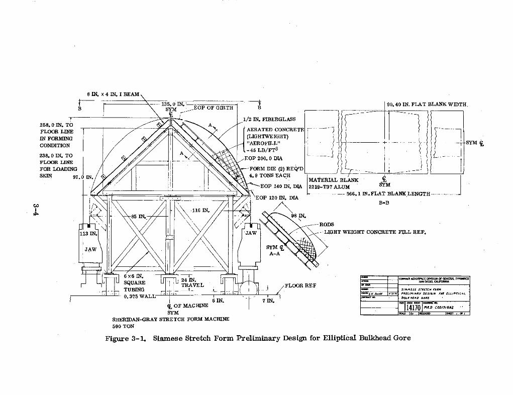
8 IN. x 4 IN. I BEAM
135.0 IN.: 90.40 IN. FLAT BLANK WIDTH.B SYM EOP OF GIRTH B! 1/2 IN. FIBERGLASS
258.0 IN. TO AFLOORLINEAERATED CONCRETE
IN FORMING (LIGHTWEIGHT)CONDITION "AEROFILL" . SYM i
O.oIN.T O ,-45 LB/FT3
238.FLOOR IN. TO EOP 200. 0 DIAFLOOR LINE -_______________ ___ ____________FOR LOADING FORM DIE (2) REQ'DSKIN 97.0 IN. 4.9 TONS EACH
MATERIAL BLANKEOP 140 IN. DIA 2219-T37 ALUM SYM
____EP10I.DA366.1 IN. FLAT BLANK LENGTH
B-B116 IN.-
85 IN. 98 IN.
-- RODS
113 IN. JAW LIGHT WEIGHT CONCRETE FILL REF.
JAW M
A-A
6 X 6 IN. CONVAIR AEROSPACE DIMVSON OF GENERAL DYAMISSQUARE 24 IN. .. SAN DIEGO, C IFON IATRAVEL FLOOR REF ""TUBING _L sSAMES srUrNc ORM
- .. 3-75 W -PRELIMIJARY DESI&N FIR ELIPrICAL
AL BULKEAD &dRE6 IN. 7 IN.
OF ACHNE14170 MiD cdOIushZSYM v
- ,SHERIDAN-GRAY STRETCH FORM MACHINE500 TON
Figure 3-1. Siamese Stretch Form Preliminary Design for Elliptical Bulkhead Gore
(45 lb/ft3 ) concrete is less than normal concrete, this concrete has proven satis-factory in large STFM dies forming aluminum parts on a production basis as largeand as thick as the subject gores.
The completed STFM dies, weighing approximately 4445.2 kg (4. 9 tons) each, willthen be installed on the substructure using the existing 4535.9 kg (5-ton) overheadhoist and bolted in position ready for stretch forming.
A discrepancy exists between the supplied Martin Co. drawings and the NASA RFQ withrespect to the contour dimensions of the LO2 and LH2 bulkheads. The drawings showthat the inside dimensions, half ellipsoids having inside major and minor axes of419.05 cm (165. 1 in.) and 314. 51 cm (123.825 in.) respectively, of the LO2 and LH2bulkheads are the same, but, the NASA contract Scope of Work states that the outsidedimensions of the two bulkheads are the same. If the NASA Scope of Work statementis correct, then a removable die cover sheet will be stretch formed of approximate0. 508 cm (0.20 in.) thick aluminum to shim the die surface out to the required moldline contour for the stretch forming of LH2 tank gores. This cover sheet cost is in-cluded in the Tooling Cost Study (see Volume II - Cost Study).
3.3 TOOLING COST STUDY
The tooling costs for the seven different configurations is discussed in Volume II - CostStudy.
3.4 PRODUCTION FLOW CHART
The production flow chart showing the major operations and tools in a proposed manu-facturing plan for any of the seven bulkhead gore configurations is shown in Figure 3-2.A simplified version of the production flow chart is shown in Figure 3-3.
The estimated average flow hours for each operation are shown on these charts. Theproduction rates at each station can be established from the fabrication rate and lotplan shown in Figure 3-4.
3.5 PRODUCTION COST STUDY
The cost studies for bulkhead gores manufacturing are contained in Volume II of thisreport.
3-5/3-6

Page intentionally left blank

PRODUCTION FLOW CHART FOR 330.2" DIA.EXTERNAL TANK DOME GORESMARTIN-MARIETTA CORP. DWG. #82600202000,82600202001, and 82600203500
0 0Numerically Controlled Siamese Stretch Forming Trimming of Gores, DrillingMachining of Gore Blank of Gores of Tooling Holes, and Contour
(3. 25 hr) (0. 5 hr) Inspection
(1. 5 hr)
.- "- '>. '"-N.
Install a Bulkhead Set of Package a Bulkhead Set ofGores on Aging Fixture Clean Gores and Protective Gores in Reusable Shipping350and Age for 18 Hours at Coat Both Sides Container and Ship
350 (1. 5 hr) (0.5 hr) (0. 7 hr)(1. 5 hr)
NOTE: Numbers in parenthesis are estimatedaverage flow hours per gore
Figure 3-3. Simplified Production Flow Chart
SHUTTLE EXTERNAL TANK DOME GORESFABRICATION RATE & LOT PLAN
CM 14-2002A13 MAY 1974
PROG(RAM YEAR
L2 TANK (10 CORE PLAN) 2 3 4 6 1 7 8 9 10 11 12 13
DELIVERY REQUIREMENTS 20 so so Iso 24o 320 400 600 600 600 600 600 240
CUI, 20 so 10so 2o0 $20 s0o 1240 1840 2440 3040 3640 4240 4480
MANUFACTURINGRATE 10 a o 0o 'Q S2o 1o o 60o 60 o So 60 1 o o S9ob 'so SO '" S 'I % % IS II 'so 'soo ' oo % 'so '50 oCUM COMPLETIONS V 4 so 0so( 40 70 126 0 1460 3 460 3060 3660 4260 s44,
LOTS PER YEAR 2 2 4 s 1 It 4s 2o o o 20 2o
CUM LOTS TOTAL I I . 24 a , 45s 63 as los I5 14S I5LOT SIZE ao so 30 3o 30 0 o o o o o
DELIVLIYV 1LQUItREIENT 40 do oo 300 - 480 o640 o00o 1oo 1o0 20oo soo 10oo 40
CUM? 40 Soo 260 560 1040 16s0 o480 3680 4880 6080 7280 -8480 8960
MANUFACTURING RATE a 16 4o o 4 40 40o o 60o do 'ao 6 ' '0 1 e ' 0 too 1 o so too 4O 1o oo loo l oo o o a bo oo% o 30 % so so so14CUM COMPLETIONS 40o o 6 08 174o 1 2Szc 2021 4920 420 722 as5G a s94
LOTS PER YEAR 1 I1 43 0 220 0 o 20 aVUM LOTS TOTAL 8 53 24 1 2 4 s 6s 8s los 1s5 1s ass
3-40 6-60LOT SIZE to 40o -60 60o 60 60o 60 60 60 o60 60 60o * 2o40
. I.)2 1ANK (12 P(l; I'ILANIDE1LJVIItY REQUIItREIEILNTS 14 if 94 SO 2 384 480 720 70 720 Il0 720 28
pUM a o is 336 64 o100 448 22o08 2928 3648 4368 o508 s76
MANUFACTURING R ATE- IS .2 4 14 42 4 14 1 4 6 36 7 2 12 72 2 0 ' O os 'o 0 oo 8 844' 4OO I' 0 i 'SO e 40 ' o ISO% I o o tI0O I0 ago 0 g IG.O too 1Igo 1 4
CUM COMPLETIONS 24 7a Igc 16 648a 1044 Isla 2232 292 367 48C s14 s7e
LOTS PER YEAR a 4 s a It 20 20o 20to 20 20o
CUM LOTS TOTAL a 4 a 4s 2 3a 4S s3 as aos 11 143 131
L.OT SIZE 12 24 16 36 36 34 3 1 6 36 66 ,6 1 41 9 T' .\K r 1 I (;a) I.lI PLAN)DELIVERY tLQUIIRL.MEINTS 48 72 192 160 S76 768 960 1 440 1440 1440 1440 1440 174
CUM 48 Io 111 672 2246 2016 2976 4416 s856 7296 736 10176 Io7sa
MANUFACTURUNG RATE 2 4 4 4 4 , 4 4g 7 4 7 ?a '7a 4 1 144 1 44 144214 16 16 16 16 1 360 60 '6 o '0 6 00 6,0 I o60 0 61 0 160 '60 0 Oa to 1 '60 Igo I%
CUM COMPLETIONS 68 84 6 72 2 zo88 so,02 4464 59so 44 874 o0224 07s:
LOTS PER YEAR 2 a 4 s S It 13 20 20o 20 20 20 a
CUM LOTS TOTAL 2 4 8 is 21 32 4s 6s 8as los S 14s 1s3IM48 IZE 24____4 4-7
LOT SIZE 4 8 72 7 2 72 a 72 72 72 ,z 7 72 .4
1 2 3 4 5 6 , 8 9 10 11 12 I 13,,_ _PROGRAM YEAR
Figure 3-4. Production Rate and Lot Plan
APPENDIXCOLD STRETCH FORMED BULKHEAD GORE DRAWING

CAP DIA OF
120. 140 & 200
TYP. GORE A EF.
15,0 2
y2
+ =1 F330.2 DIA 165.12 123.8252
6 DEG
VIEW F
A B C D
D LH 2 0. 075 0. 169 0.150 0. 075
LO 2 0.170 0.380 0.222 0.162
6 DEG
NOTE: ALL DIMENSIONS FROM MARTIN MARIETTA CORP.
DRAWINGS 82600203500, 82600202000-1. DIMENSIONS1.50 VIEW G ARE IN INCHES UNLESS OTHERWISE MARKED
G
15.0
NOT TO SCALE
COLD STRETCH FORMED BULKHEAD GORE